t -s e rie s · t -s e rie s in sta lla tio n a ... chapter2:handbookinformation chaptercontents...
TRANSCRIPT

T-S e r ie s
Ins ta lla tion and opera tionins tructions
Englis hDate : 08-2012Document number: 81338-3-EN © 2012 Raymarine UK Limited
T-Series


Trademarks and patents noticeAutohelm, hsb2, RayTech Navigator, Sail Pilot, SeaTalk, SeaTalkNG, SeaTalkHS and Sportpilot are registered trademarks of RaymarineUK Limited. RayTalk, Seahawk, Smartpilot, Pathfinder and Raymarine are registered trademarks of Raymarine Holdings Limited.FLIR is a registered trademark of FLIR Systems, Inc. and/or its subsidiaries.All other trademarks, trade names, or company names referenced herein are used for identification only and are the property oftheir respective owners.This product is covered by one or more of US Patent Nos: 7470904; 7034301; 6812465; 7470902; 6929410 and other patentspending, or design patents pending.
Fair Use StatementYou may print no more than three copies of this manual for your own use. You may not make any further copies or distribute or use themanual in any other way including without limitation exploiting the manual commercially or giving or selling copies to third parties.
Export controlT303, T403, T453, T463, T470SC and T473SC thermal cameras are controlled by US export laws.There are special versions of the system that are approved for international distribution and travel. Please contact Raymarine customersupport if you have any questions.Contact details can be found on the Raymarine website, www.raymarine.com.
Export Administration Regulations (EAR)This document is controlled to Raymarine Technology Level 1. The information contained in this document pertains to a dual useproduct controlled for export by the Export Administration Regulations (EAR). Raymarine trade secrets contained herein are subject todisclosure restrictions as a matter of law. Diversion contrary to US law is prohibited. US Department of Commerce authorization is notrequired prior to export or transfer to foreign persons or parties unless otherwise prohibited.
Software updatesCheck the website www.raymarine.com for the latest software releases for your product.
Product handbooks
The latest versions of all English and translated handbooks are available to download in PDF format from the website www.raymarine.com.Please check the website to ensure you have the latest handbooks.
Copyright ©2012 Raymarine UK Ltd. All rights reserved.
ENGLISHDocument number: 81338-3Date: 08-2012


ContentsChapter 1 Important information............................. 7Cleaning the thermal camera........................................... 7Water ingress ................................................................. 7Disclaimers .................................................................... 7EMC installation guidelines ............................................. 8Suppression ferrites........................................................ 8Connections to other equipment ...................................... 8Declaration of conformity................................................. 8Product disposal ............................................................. 8Warranty registration....................................................... 8IMO and SOLAS............................................................. 8Technical accuracy ......................................................... 8
Chapter 2 Handbook information............................ 92.1 Handbook information ............................................... 102.2 T-Series thermal imaging cameras ............................. 10
Chapter 3 Planning the installation ........................113.1 Thermal camera system ............................................ 123.2 Installation checklist .................................................. 133.3 Typical systems with thermal cameras........................ 143.4 Thermal camera parts supplied .................................. 163.5 JCU — Parts supplied ............................................... 163.6 Tools required ........................................................... 17
Chapter 4 Cables and connections.........................194.1 General cabling guidance .......................................... 204.2 Connection overview ................................................. 204.3 Power connection ..................................................... 214.4 JCU Connection........................................................ 22
Chapter 5 Installation...............................................255.1 Camera mounting ..................................................... 265.2 JCU Mounting........................................................... 27
Chapter 6 System operation and setup..................296.1 Thermal camera image.............................................. 306.2 Operation and features overview................................ 316.3 Power up and standby............................................... 326.4 Camera control ......................................................... 326.5 Image adjustments.................................................... 336.6 System reset ............................................................ 346.7 Setup menus ............................................................ 35
Chapter 7 Troubleshooting and support ................377.1 Thermal camera troubleshooting ................................ 387.2 Raymarine customer support ..................................... 39
Chapter 8 Technical specification...........................418.1 Technical specification............................................... 42
5

6 T-Series

Chapter 1: Important informationWarning: Product installation andoperationThis product must be installed and operated inaccordance with the instructions provided. Failure todo so could result in personal injury, damage to yourvessel and/or poor product performance.
Warning: Potential ignition sourceThis product is NOT approved for use inhazardous/flammable atmospheres. Do NOT install ina hazardous/flammable atmosphere (such as in anengine room or near fuel tanks).
Warning: Product groundingBefore applying power to this product, ensure it hasbeen correctly grounded, in accordance with theinstructions in this guide.
Warning: Switch off power supplyEnsure the vessel’s power supply is switched OFFbefore starting to install this product. Do NOT connector disconnect equipment with the power switched on,unless instructed in this document.
Warning: Entrapment hazardThis product features moving parts that provide apotential entrapment hazard. Keep clear of movingparts at all times.
Warning: Ensure safe navigationThis product is intended only as an aid to navigationand must never be used in preference to soundnavigational judgment. Only official governmentcharts and notices to mariners contain all the currentinformation needed for safe navigation, and thecaptain is responsible for their prudent use. It is theuser’s responsibility to use official government charts,notices to mariners, caution and proper navigationalskill when operating this or any other Raymarineproduct.
Warning: Maintain a permanent watchAlways maintain a permanent watch, this will allowyou to respond to situations as they develop. Failureto maintain a permanent watch puts yourself, yourvessel and others at serious risk of harm.
Caution: Do not open the unitThe unit is factory sealed to protect againstatmospheric humidity, suspended particulates andother contaminates. It is important that you do notopen the unit or remove the casing for any reason.Opening the unit will:
• compromise the seal with possible damage to theunit, and
• void the manufacturer’s warranty.
Caution: Power supply protectionWhen installing this product ensure the power sourceis adequately protected by means of a suitably-ratedfuse or automatic circuit breaker.
Caution: Service and maintenanceThis product contains no user serviceablecomponents. Please refer all maintenance and repairto authorized Raymarine dealers. Unauthorized repairmay affect your warranty.
Caution: Sun covers• To protect your product against the damagingeffects of ultraviolet (UV) light, always fit the suncovers when the product is not in use.
• Remove the sun covers when travelling at highspeed, whether in water or when the vessel is beingtowed.
Cleaning the thermal cameraThe camera housing and lens will require occasional cleaning.Raymarine suggests that you clean the lens when image qualitydegradation is noticed or excessive contaminant buildup is seen.Clean the interface between the yoke and base often to preventaccumulation of debris or salt deposits.
When cleaning this product:• Do NOT wipe the lens window with a dry cloth, as this couldscratch the coating.
• Do NOT use abrasive, or acid or ammonia based products.• Do NOT pressure wash.
Particular care should be taken when cleaning the lens window, thishas a protective anti-reflective coating which may be damaged byimproper cleaning.1. Switch off the power to the unit.2. Clean the camera body with a clean, soft cotton cloth. You can
moisten the cloth and use a mild detergent if required.3. Clean the camera lens.
• Rinse the lens with fresh water to remove all dirt particles andsalt deposits, and allow to dry naturally.
• If any spots or smears remain, very gently wipe the lenswindow with a clean microfibre cloth or soft cotton cloth.
• If necessary, use isopropyl alcohol (IPA) or a mild detergent toremove any remaining spots or marks.
Water ingressWater ingress disclaimerAlthough the waterproof rating capacity of this product meets theIPX6 standard, water intrusion and subsequent equipment failuremay occur if the product is subjected to commercial high-pressurewashing. Raymarine will not warrant products subjected tohigh-pressure washing.
DisclaimersThis product (including the electronic charts) is intended to be usedonly as an aid to navigation. It is designed to facilitate use of officialgovernment charts, not replace them. Only official governmentcharts and notices to mariners contain all the current informationneeded for safe navigation, and the captain is responsible for theirprudent use. It is the user’s responsibility to use official governmentcharts, notices to mariners, caution and proper navigational skillwhen operating this or any other Raymarine product. This productsupports electronic charts provided by third party data supplierswhich may be embedded or stored on memory card. Use of suchcharts is subject to the supplier’s End-User Licence Agreementincluded in the documentation for this product or supplied with thememory card (as applicable).Raymarine does not warrant that this product is error-free or that itis compatible with products manufactured by any person or entityother than Raymarine.
Important information 7

This product uses digital chart data, and electronic information fromthe Global Positioning System (GPS) which may contain errors.Raymarine does not warrant the accuracy of such information andyou are advised that errors in such information may cause theproduct to malfunction. Raymarine is not responsible for damagesor injuries caused by your use or inability to use the product, by theinteraction of the product with products manufactured by others, orby errors in chart data or information utilized by the product andsupplied by third parties.
EMC installation guidelinesRaymarine equipment and accessories conform to the appropriateElectromagnetic Compatibility (EMC) regulations, to minimizeelectromagnetic interference between equipment and minimize theeffect such interference could have on the performance of yoursystemCorrect installation is required to ensure that EMC performance isnot compromised.For optimum EMC performance we recommend that whereverpossible:
• Raymarine equipment and cables connected to it are:
– At least 1 m (3 ft) from any equipment transmitting or cablescarrying radio signals e.g. VHF radios, cables and antennas.In the case of SSB radios, the distance should be increasedto 7 ft (2 m).
– More than 2 m (7 ft) from the path of a radar beam. A radarbeam can normally be assumed to spread 20 degrees aboveand below the radiating element.
• The product is supplied from a separate battery from that usedfor engine start. This is important to prevent erratic behaviorand data loss which can occur if the engine start does not havea separate battery.
• Raymarine specified cables are used.
• Cables are not cut or extended, unless doing so is detailed inthe installation manual.
Note: Where constraints on the installation prevent any ofthe above recommendations, always ensure the maximumpossible separation between different items of electricalequipment, to provide the best conditions for EMC performancethroughout the installation
Suppression ferritesRaymarine cables may be fitted with suppression ferrites. Theseare important for correct EMC performance. If a ferrite has to beremoved for any purpose (e.g. installation or maintenance), it mustbe replaced in the original position before the product is used.Use only ferrites of the correct type, supplied by Raymarineauthorized dealers.
Connections to other equipmentRequirement for ferrites on non-Raymarine cablesIf your Raymarine equipment is to be connected to other equipmentusing a cable not supplied by Raymarine, a suppression ferriteMUST always be attached to the cable near the Raymarine unit.
Declaration of conformityRaymarine UK Ltd. declares that this product is compliant with theessential requirements of EMC directive 2004/108/EC.The original Declaration of Conformity certificate may be viewed onthe relevant product page at www.raymarine.com.
Product disposalDispose of this product in accordance with the WEEE Directive.
The Waste Electrical and Electronic Equipment (WEEE)Directive requires the recycling of waste electrical and electronicequipment. Whilst the WEEE Directive does not apply to someRaymarine products, we support its policy and ask you to be awareof how to dispose of this product.
Warranty registrationTo register your Raymarine product ownership, please visitwww.raymarine.com and register online.It is important that you register your product to receive full warrantybenefits. Your unit package includes a bar code label indicating theserial number of the unit. You will need this serial number whenregistering your product online. You should retain the label for futurereference.
IMO and SOLASThe equipment described within this document is intended for useon leisure marine boats and workboats not covered by InternationalMaritime Organization (IMO) and Safety of Life at Sea (SOLAS)Carriage Regulations.
Technical accuracyTo the best of our knowledge, the information in this documentwas correct at the time it was produced. However, Raymarinecannot accept liability for any inaccuracies or omissions it maycontain. In addition, our policy of continuous product improvementmay change specifications without notice. As a result, Raymarinecannot accept liability for any differences between the productand this document. Please check the Raymarine website(www.raymarine.com) to ensure you have the most up-to-dateversion(s) of the documentation for your product.
8 T-Series

Chapter 2: Handbook information
Chapter contents• 2.1 Handbook information on page 10
• 2.2 T-Series thermal imaging cameras on page 10
Handbook information 9

2.1 Handbook informationThis handbook describes the installation and operation of RaymarineT-Series thermal cameras as part of a marine electronics system.It provides an overview of features available and examples of thecontrols used.This handbook covers models: T300, T303, T350, T353, T400,T403, T450, T453, T460, T463, T470SC and T473SC. It includesinformation to help you:
• plan your thermal imaging system and ensure you have all thenecessary equipment,
• install and connect the thermal camera as a part of your systemof Raymarine electronics,
• operate the thermal camera system,
• set up the thermal camera system using the on-screen menus,
• obtain support if required.
The handbook is for use with the following products:
• T300 – QVGA Thermal camera
• T303 – QVGA Thermal camera (30 Hz)
• T350 – VGA Thermal camera
• T353 – VGA Thermal camera (30 Hz)
• T400 – QVGA dual payload camera
• T403 – QVGA dual payload camera (30 Hz)
• T450 – VGA dual payload camera
• T453 – VGA dual payload camera (30 Hz)
• T460 – VGA dual payload camera
• T463 – VGA dual payload camera (30 Hz)
• T470SC — VGA dual payload stabilized color camera
• T473SC — VGA dual payload stabilized color camera (30 Hz)
Thermal camera handbooksDescription Part number
T-Series thermal cameras installation and operationhandbookInstallation, commissioning and operation instructions forT-Series thermal camera systems.
81338
2.2 T-Series thermal imaging camerasT-Series is a maritime thermal imaging system for use on nearly anykind of vessel. It provides a clear image in low-light and no-lightconditions. For example, a thermal camera can help you navigateat night or identify obstacles in areas of low visibility or even totaldarkness.
D11974-2
1
2
3
1. Thermal camera lens window
2. Visible light camera lens window
3. Gimbal assembly
The T-Series system has the following key functions and features:
• Pan, tilt and zoom operations.
• Automatic camera adjustment to suit changing conditions.
• Preset modes (Scenes) optimized for prevailing conditions.
• Automatic window heaters to de-ice the lens window in coldweather.
• Single and dual payload configurations. (T400, T403, T450,T453, T460 and T463 are dual payload models with both thermaland visible light (greyscale) capability to enhance low lightperformance.)
• The T470SC and T473SC models includes a mechanicalstabilization feature which improves image stability bycompensating for vessel motion and both thermal and continuouszoom color visible light camera.
10 T-Series

Chapter 3: Planning the installation
Chapter contents• 3.1 Thermal camera system on page 12
• 3.2 Installation checklist on page 13
• 3.3 Typical systems with thermal cameras on page 14
• 3.4 Thermal camera parts supplied on page 16
• 3.5 JCU — Parts supplied on page 16
• 3.6 Tools required on page 17
Planning the installation 11

3.1 Thermal camera systemA typical thermal camera system comprises the items shown below:
D11966-2
1
2 3
1. Thermal camera
2. Controller – This provides the controls to operate and configurethe camera.
3. Display – This displays the thermal video image as wellas status information and on-screen menus provided by thecamera.
Note: The controller and display may be the same device. SomeRaymarine multifunction displays provide a thermal cameraapplication which has a set of integral camera controls.
Additional controllers and equipmentYou may have additional equipment as part of your thermal camerasystem:
• Multiple controllers and displays, for example a camera servingmultiple display / control stations.
• SeaTalkhs network switch – Used to create a network ofcompatible Raymarine equipment.
• GVM video module – Used to distribute the video signal around aRaymarine G-Series system.
Compatible displays and controllersThe following Raymarine displays and systems are compatible withthe T-Series range of thermal cameras.
Multifunction displaysystem Direct video Network video
Integratedcameracontrols
c-series — c95, c97,c125 , c127
● ●
e-series — e7, e7D,e95, e97, e125, e127
● ●
G-Series system ● (directto G-Seriesmonitor)
● (usingGVM400 videomodule)
●
E-Series Widescreen— E90W, E120W,E140W
● ●
Multifunction displaysystem Direct video Network video
Integratedcameracontrols
C-Series Widescreen— C90W, C120W,C140W
●
E-Series Classic —E80, E120
●
Note: Displays without integrated camera controls require aseparate JCU (Joystick Control Unit).
Dedicated camera controllers
Controller Description
Joystick controlunit (JCU)
Dedicated thermal camera controller, featuring 3 axis puckcontrol, function keys and an LCD display.
12 T-Series
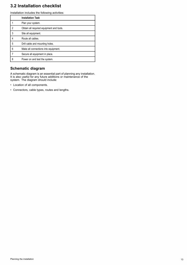
3.2 Installation checklistInstallation includes the following activities:
Installation Task
1 Plan your system.
2 Obtain all required equipment and tools.
3 Site all equipment.
4 Route all cables.
5 Drill cable and mounting holes.
6 Make all connections into equipment.
7 Secure all equipment in place.
8 Power on and test the system.
Schematic diagramA schematic diagram is an essential part of planning any installation.It is also useful for any future additions or maintenance of thesystem. The diagram should include:
• Location of all components.
• Connectors, cable types, routes and lengths.
Planning the installation 13

3.3 Typical systems with thermal camerasExample system with fully integrated display
6
D11964-2
1 3 4 52
Video cable – Carries the thermal / visible light video image. SeaTalkhs – Includes the camera control communications.
1 e/c-series display 4 PoE injector (Required if JCU is included in the system.)
2 Thermal camera 5 JCU (optional)
3 Raymarine network switch 6 SeaTalkhs to other digital devices: Additional displays / controllers, Radar,etc.
G-Series system99WWXXYYZZ88TTUUVV77PPQQRRSS44GGHHII55JJKKLL66MMNNOOAACCTTIIVVEEWWPPTTSSMMOOBBDDAATTAAMMEENNUUPPAAGGEE..0022AABBCC33DDEEFF11CCAANNCCEELLSSTTAANNDDBBYYDDOODDGGEEPPIILLOOTTOOKKRRAANNGGEEOOUUTTIINNEENNTTEERRD11965-2
3 4
6 8 9
1 2
5 7
Video cable SeaTalkhs – Includes the camera control communications (and videosignal on G-Series system).
1 G-Series Nav station 6 G-Series GVM400 video module
2 Repeat monitor 7 Thermal camera
3 G-Series GPM400 8 JCU (optional)
4 Raymarine network switch 9 PoE injector (Required if JCU is included in the system.)
5 Glass bridge monitor
14 T-Series

System with basic / classic display(s)This arrangement is applicable for displays which do not have the thermal camera application and integrated camera controls.
D11978-2
1
3
2
Video cable – Carries the thermal / visible light video image.
Ethernet – Includes the camera control
1 Thermal camera
2 JCU (required)
3 Monitor / Display
SeaTalkhsSeaTalkhs is an ethernet based marine network. This high speedprotocol allows compatible equipment to communicate rapidly andshare large amounts of data.Information shared using the SeaTalkhs network includes:
• Shared cartography (between compatible displays).
• Digital radar data.
• Sonar data.
Planning the installation 15

3.4 Thermal camera parts supplied
x6 x6 x6
x6
D11968-2
2
5
6
1
3
4
1. T-Series thermal camera
2. Mounting fasteners
3. Ethernet waterproof coupler
4. Small O-ring
5. Documentation pack (containing: camera mounting template,warranty policy and documentation CD.)
6. Large O-ring
Unpack the camera unit carefully to prevent damage. Save thecarton and packing in case the unit has to be returned for service.
Additional items requiredTo complete the installation you will also need to obtain the followingitems:
• Compatible display / control hardware.
• Cables for power, ground, video and network connection.
• Thread locking compound (for example Loctite 242 or equivalent),required for all metal-to-metal threaded connections.
Optional accessoriesYou may also require the following items:
• Top Down Installation Kit (plate or riser). Required if the camerais to be mounted on a surface with no access to the underside (forexample on top of a sealed enclosure).
3.5 JCU — Parts suppliedT-Series thermal cameras with JCU included are supplied with thefollowing additional parts:
D11967-2
1
3
2
4
5
78.74 ±1.25 mm (3.1 ±0.049 in) cutout6.4 mm(0.25 in)diameter
72.4 mm (2.9 in) optional drill guide
90.4 mm (3.6 in) outside of JCU
129.
54 ±
1.25
mm
(5.1
±0.
049
in) c
utou
t
123.
2 m
m (4
.9 in
) opt
iona
l dril
l gui
de
141.
4 m
m (5
.6 in
) out
side
of J
CU
This
doc
umen
t may
not
prin
t tru
e to
sca
le. B
efor
e m
odify
ing
mou
ntin
g su
rface
, ens
ure
prin
ted
tem
plat
e m
atch
es th
e m
easu
rem
ents
pro
vide
d.
D11
991
-1
6
1. Joystick Control Unit (JCU).
2. Bezel.
3. Sun cover.
4. Mounting template
5. Power over Ethernet (PoE) injector.
6. PoE cable 7.62m (25').
Note: The JCU part number E32130 can also be orderedseparately.
16 T-Series

3.6 Tools requiredThe following tools are required for installation.
D12333-1
1 2
3
4 5
6
Item Description
1. Drill
2. 6mm spanner
3. 6.4mm drill bit
4. Jigsaw (only required for JCUinstallation)
5. Pozi-drive screwdriver (only requiredfor JCU installation)
6. Thread-lock
Planning the installation 17

18 T-Series

Chapter 4: Cables and connections
Chapter contents• 4.1 General cabling guidance on page 20
• 4.2 Connection overview on page 20
• 4.3 Power connection on page 21
• 4.4 JCU Connection on page 22
Cables and connections 19

4.1 General cabling guidance
Cable types and lengthIt is important to use cables of the appropriate type and length
• Unless otherwise stated use only standard cables of the correcttype, supplied by Raymarine.
• Ensure that any non-Raymarine cables are of the correct qualityand gauge. For example, longer power cable runs may requirelarger wire gauges to minimize voltage drop along the run.
Routing cablesCables must be routed correctly, to maximize performance andprolong cable life.
• Do NOT bend cables excessively. Wherever possible, ensure aminimum bend diameter of 200 mm (8 in) / minimum bend radiusof 100 mm (4 in).
100 mm (4 in)
200 mm (8 in)
• Protect all cables from physical damage and exposure to heat.Use trunking or conduit where possible. Do NOT run cablesthrough bilges or doorways, or close to moving or hot objects.
• Secure cables in place using tie-wraps or lacing twine. Coil anyextra cable and tie it out of the way.
• Where a cable passes through an exposed bulkhead or deckhead,use a suitable watertight feed-through.
• Do NOT run cables near to engines or fluorescent lights.
Always route data cables as far away as possible from:
• other equipment and cables,
• high current carrying ac and dc power lines,
• antennae.
Strain reliefEnsure adequate strain relief is provided. Protect connectors fromstrain and ensure they will not pull out under extreme sea conditions.
Circuit isolationAppropriate circuit isolation is required for installations using bothAC and DC current:
• Always use isolating transformers or a separate power-inverterto run PC’s, processors, displays and other sensitive electronicinstruments or devices.
• Always use an isolating transformer with Weather FAX audiocables.
• Always use an isolated power supply when using a 3rd partyaudio amplifier.
• Always use an RS232/NMEA converter with optical isolation onthe signal lines.
• Always make sure that PC’s or other sensitive electronic deviceshave a dedicated power circuit.
Cable shieldingEnsure that all data cables are properly shielded that the cableshielding is intact (e.g. hasn’t been scraped off by being squeezedthrough a tight area).
4.2 Connection overview
D11957-1
21 43
5
1. Power and drain
2. IR out – Thermal camera video
3. SeaTalkhs – To Raymarine network switch or JCU
4. VIS / IR out – Visible light and thermal video. (Dual payloadonly, VIS / IR are switched using camera controls.)
5. Low impedance ground connection
Connection care points:
• You must provide a low impedance chassis to ground connection,this is made to any one of the chassis threaded fixing points andis in addition to the drain-to-ground connection.
• The 450 mm (18in) cable tails should be routed to a dry area ofthe vessel for connection. Alternatively you must ensure that allconnections are made water tight.
• Ensure that the VIS/IR feed is connected on dual payload models.Without this connection the user will not be able to use thecamera controllers to switch between the thermal and low light(visible) camera images.
Thermal camera cablesCabling requirements for thermal cameras.
Camera to network switchA network patch cable is required to connect the camera to thenetwork switch. The connection is made between the cameracable tail and the network switch via the coupler (supplied with thecamera). Network patch cables are available in a variety of lengths.
Joystick Control Unit (JCU)An Ethernet (with power) cable is used to connect the JCU. The JCUis supplied with a 7.62 m (25 ft) Ethernet cable for this connection. Ifyou require a different length contact your dealer for suitable cables.
Power over Ethernet (PoE) injector to network switchA network patch cable is required for connecting the PoE injectorto the network switch. Network patch cables are available in avariety of lengths.
Video cablesVideo cables are not supplied with the product. Please contact yourdealer for suitable cables and adaptors.Raymarine recommends the use of a BNC terminated RG59 75ohm(or better) coaxial cable.
20 T-Series

SeaTalkhs patch cablesCable Part number
1.5 m (4.9 ft) SeaTalkhs patch cable E06054
5 m (16.4 ft) SeaTalkhs patch cable E06055
10 m (32.8 ft) SeaTalkhs patch cable E06056
15 m (49.2 ft) SeaTalkhs patch cable A62136
20 m (65.6 ft) SeaTalkhs patch cable E06057
4.3 Power connectionPower must be supplied to the camera from an appropriate powersource.
Power connection requirements
• 12 or 24 Vdc nominal supply voltage
• Isolated power supply
• Connected via an appropriately rated thermal breaker or fusedswitch.
Power connection colors
Color Description
Red Power in +ve (12 / 24 V)
Black Power in -ve (0 V)
Green Drain / Ground
Power cableThe power connection is made to a 450 mm (18 in) tail out of thecamera base. Extend this tail with appropriate cable as per the tablebelow.
Total length (max) Supply voltage Cable size
12 V 1.5 mm2 (16 AWG)0–8 m (25 ft)
24 V 0.8 mm2 (18 AWG)
12 V 2.0 mm2 (14 AWG)8–16 m (50 ft)
24 V 0.8 mm2 (18 AWG)
12 V 3.5 mm2 (12 AWG)16–24 m (75 ft)
24 V 0.8 mm2 (18 AWG)
12 V 5.5 mm2 (10 AWG)24–32 m (100 ft)
24 V 0.8 mm2 (18 AWG)
Breakers, fuses and circuit protectionRaymarine recommends that you fit a thermal breaker or fuse forthe camera at the distribution panel.
Camera Recommended fuse
All models 5 Amp.
Sharing a breakerWhere more than 1 piece of equipment shares a breaker you mustprovide protection for the individual circuits. E.g. by connecting anin-line fuse for each power circuit.
D11
637-
1
+VE bar
Circuit breaker
FuseFuse
-VE bar
Where possible, connect individual items of equipment to individual circuit breakers.
Where this not possible, use individual in-line fuses to provide the necessary protection.
Cables and connections 21
Grounding — Dedicated drain wireThe power cable supplied with this product includes a dedicatedshield (drain) wire for connection to a vessel's RF ground point.It is important that an effective RF ground is connected to thesystem. A single ground point should be used for all equipment.The unit can be grounded by connecting the shield (drain) wire ofthe power cable to the vessel's RF ground point. On vessels withoutan RF ground system the shield (drain) wire should be connecteddirectly to the negative battery terminal.The dc power system should be either:
• Negative grounded, with the negative battery terminal connectedto the vessel's ground.
• Floating, with neither battery terminal connected to the vessel'sground
Warning: Positive ground systemsDo not connect this unit to a system which has positivegrounding.
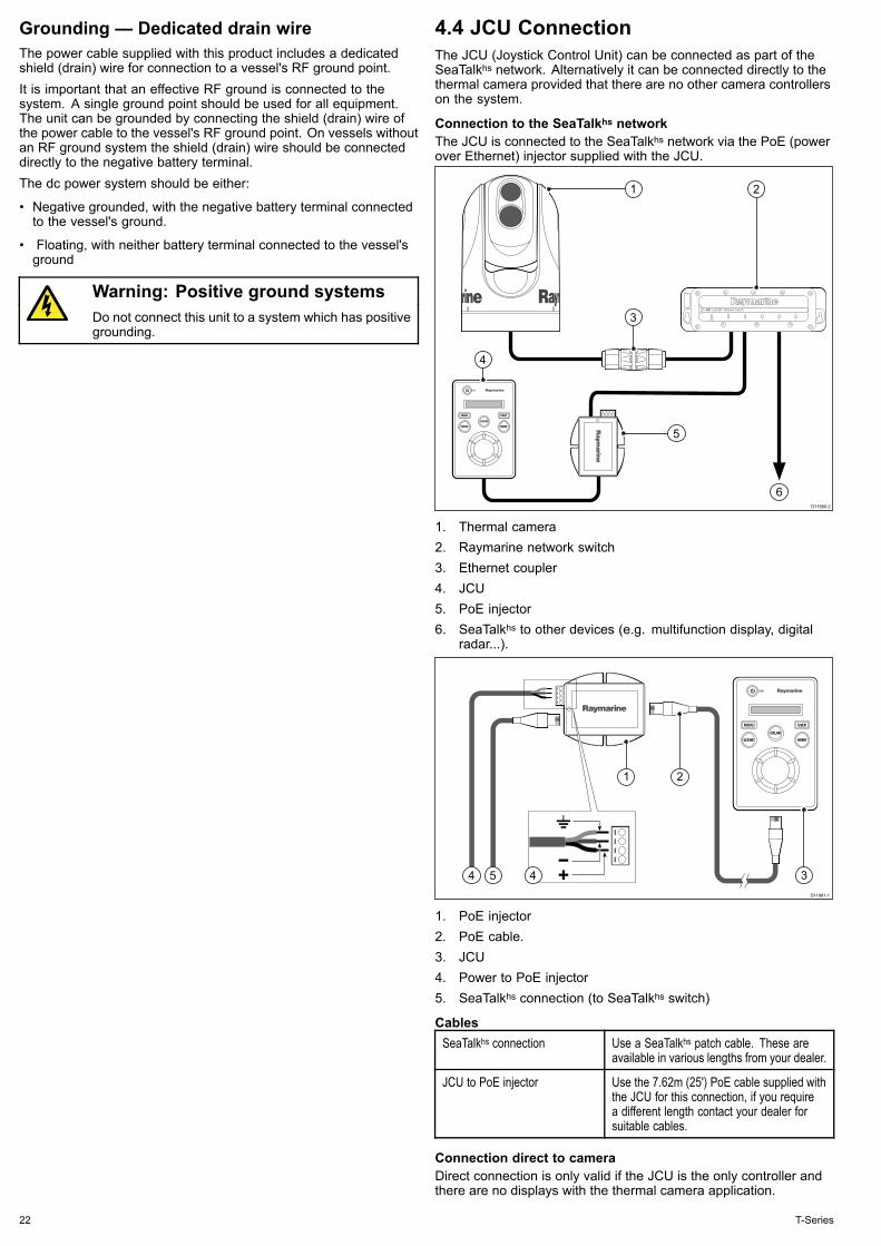
4.4 JCU ConnectionThe JCU (Joystick Control Unit) can be connected as part of theSeaTalkhs network. Alternatively it can be connected directly to thethermal camera provided that there are no other camera controllerson the system.
Connection to the SeaTalkhs networkThe JCU is connected to the SeaTalkhs network via the PoE (powerover Ethernet) injector supplied with the JCU.
D11980-2
1
5
3
4
6
2
1. Thermal camera2. Raymarine network switch3. Ethernet coupler4. JCU5. PoE injector6. SeaTalkhs to other devices (e.g. multifunction display, digital
radar...).
D11981-1
54 4
21
3
1. PoE injector2. PoE cable.3. JCU4. Power to PoE injector5. SeaTalkhs connection (to SeaTalkhs switch)
CablesSeaTalkhs connection Use a SeaTalkhs patch cable. These are
available in various lengths from your dealer.
JCU to PoE injector Use the 7.62m (25') PoE cable supplied withthe JCU for this connection, if you requirea different length contact your dealer forsuitable cables.
Connection direct to cameraDirect connection is only valid if the JCU is the only controller andthere are no displays with the thermal camera application.
22 T-Series

D11979-1
1 2
3
1. Thermal camera
2. JCU
3. Ethernet coupler, supplied with camera
Cables
Camera to Ethernet coupler Use the 450 mm (18 ”) tail hard wired fromthe camera. Should you need to extend thisuse a SeaTalkhs patch cable and additionalcoupler available from your dealer.
JCU to Ethernet coupler Use the 7.62m (25') PoE cable supplied withthe JCU for this connection, if you requirea different length contact your dealer forsuitable cables.
Cables and connections 23

24 T-Series

Chapter 5: Installation
Chapter contents• 5.1 Camera mounting on page 26
• 5.2 JCU Mounting on page 27
Installation 25

5.1 Camera mounting
Location requirementWhen planning the installation location, consider the followingpoints:
• The camera is waterproof, and appropriate for above decksmounting.
• The underside (inside) of the compartment or deck onto whichthe camera is mounted must be weathertight. You must ensureprotection from water ingress to cables and connections.
• The mounting surface must be horizontal.
• If you cannot access both sides of the mounting surface, then youwill need the optional “top down mounting kit”.
• Mounting screws are supplied for a mounting surface of up to41 mm (1.6 in) thick. A thicker surface will require the installer toprovide alternative fasteners.
• The camera mounting surface must be at least as large as thefootprint of the camera itself to ensure an adequate seal with theO-ring.
• The camera should be mounted as high as practical, but withoutinterfering with any radar, navigational or communicationselectronics.
• Choose a location that will provide the most unobstructed view inall directions.
• Choose a location as close to the vessel’s center line as possible.This provides a symmetrical view when looking forward or aft.
• Select a location that is at least 1 m (3 ft) from devices thatmay cause interference, such as motors, generators and radiotransmitters / receivers.
Camera orientationThe camera can be mounted in 2 orientations informally known as“Ball up” and “Ball down”.
Note: The stabilized variants of the T-Series thermal camerasMUST be mounted in the ball up configuration.
D11975-1
Ball up: The camera is mounted ontop of the mounting surface.
D11976-1
Ball down: The camera is suspendedupside down, below the mountingsurface.
Note: For ball down mounting you must set the ball down optionin the camera system setup menu appropriately.
Mounting the cameraUse these instructions to mount the camera unit in position.
D11971-1
1. Using the template supplied, mark and drill the holes formounting the camera.
Mounting holes care points:
• Check the dimensions of any printed template (to ensure thatthe template is printed to the correct scale) prior to drilling anyholes.
• Note the camera forward markings on the camera base, andmake sure the template is oriented properly relative to the bowof the vessel. This is affected by whether the camera is to bemounted ball-up or ball-down.
2. Install the 6x threaded studs into the base of the camera withthread-locking compound. If required, you can use studs of adifferent length to suit your installation.
Tighten the studs to a torque of 9.5 Nm (7 lb-ft).3. Install the rubber O-ring in the base of the camera.4. Thread the power supply, video, and network cables from the
camera through the center hole, and then place the camera onthe mounting surface (or top-down riser if applicable) so thethreaded studs extend through the drilled holes.
5. Make the required cable connections to the camera tails.6. Secure the camera body to the mounting surface with the
supplied nuts and washers.
Dome capped nuts are provided for a neater solution where themounting is exposed to view.
You must ensure a watertight seal. You may use a marine-gradesealant as an alternative to the mounting O-ring.
Mounting the camera with the top-down kitThe top-down mounting kit is used when access to the undersideof the mounting surface is restricted. Use the instructions below tomount the camera unit using a top-down mounting kit.1. Use the top-down riser as a template to mark and drill the holes
for mounting the camera.
26 T-Series

2. Fasten the camera unit to the riser using the 6x threaded boltsand a suitable thread-locking compound.
D11970-1
• Note the camera forward markings on the camera base.You must ensure that the camera is facing the correct waydepending upon whether the camera is to be mounted ball-upor ball-down.
• Ensure the rubber O-ring is positioned correctly in the baseof the camera.
3. Make the required cable connections to the camera tails.4. Fasten the camera-riser assembly to the mounting surface using
the fasteners supplied.
D11977-1
You must ensure a watertight seal. You may use a marine-gradesealant as an alternative to the mounting O-ring.
5.2 JCU Mounting
Location requirementsWhen planning the installation location, consider the followingpoints:
• Select a position on your vessel that is close to the monitor thatdisplays the T-Series camera video output.
• Ensure the JCU is mounted at least 55 cm (21.7") away from anyequipment fitted with a magnetic compass.
• The JCU can be mounted to a dash or other surface in anyorientation.
• Consider cable lengths and cable routing.
Flush mountingThe standard method for mounting the JCU is a flush or panelmounting arrangement.Before mounting the unit, ensure that you have:
• Selected a suitable location. A clear, flat area with suitableclearance behind the panel is required.
• Identified the cable connection required and the route that thecable will take.
• Detached the front bezel to reveal the mounting screws.
Mounting the JCU1. Cut the mounting hole according to the dimensions specified in
the mounting template included in this document.2. Ensure that the unit fits into the removed area and then file
around the cut edge until smooth.3. Drill four 6.4 mm (0.25 in) holes as indicated on the template to
accept the mounting screws.4. Before mounting the JCU, insert the supplied ethernet cable
through the mounting hole and into the JCU ethernet port.Ensure the cable gland sealing nut is tightened correctly.
5. Remove the 4 panel mounting clamps and insert the JCU inplace. Affix the mounting clamps to the screws on the other sideof the mounting surface, ensuring that the mounting clampsare rotated outward from the JCU housing. Tighten the screwsto draw the mounting clamps up against the mounting surfaceand then tighten another 1/4 to 1/2 turn. Do not overtighten thescrews.i. As shipped from the factory, the JCU can be mounted to a
panel thickness ranging from 0.79 to 4.45 cm (0.31 to 1.750in). The clamps are set with the small “foot” on the clampfacing towards the mounting surface, away from the front ofthe JCU, as shown in the "Thick panel mounting" diagramin this document.
ii. To mount the JCU to a panel thickness of 0.79 cm (0.31 in) orless, remove the clamps from the mounting screws, turn themaround and thread them back onto each of the four screws.In this configuration, the clamp “foot” faces away from themounting surface and allows the clamp to contact thinnerpanel surfaces while still allowing for proper compressionof the JCU mounting gasket to form a watertight seal. Thismounting configuration is shown in the "Thin panel mounting"diagram in this document.
6. Once you have secured the JCU in place, replace the bezel.
Installation 27

Thin panel mounting
D11
989-
1
Thick panel mounting
D11
990-
1
28 T-Series

Chapter 6: System operation and setup
Chapter contents• 6.1 Thermal camera image on page 30
• 6.2 Operation and features overview on page 31
• 6.3 Power up and standby on page 32
• 6.4 Camera control on page 32
• 6.5 Image adjustments on page 33
• 6.6 System reset on page 34
• 6.7 Setup menus on page 35
System operation and setup 29

6.1 Thermal camera imageThe thermal camera provides a video image which is shown onyour display.
The video feed provides:• Thermal image• Status icons / system information (e.g. camera direction anddocking mode indicators in the example above).
You should take time to familiarize yourself with the thermal image.This will help you to make the most of your system:• Consider every object you view in terms of how it will look“thermally” as opposed to how it looks to your eye. For examplelook for changes caused by the heating effect of the sun. Theseare particularly evident right after sunset.
• Experiment with white-hot and black-hot (reverse video) modes.• Experiment by looking for hot objects (such as people) comparedto the colder surroundings.
• Experiment with the camera for daytime viewing. The cameracan provide improved daytime viewing in environments wheretraditional video camera performance suffers, such as in shadowsor backlit scenes.
Thermal camera status iconsThe thermal camera image includes icons to show the current statusof the camera.Icon Description
Camera direction indicator.
Camera home position.
Camera paused.
Scene preset mode for night conditions.
Scene preset mode for daytime conditions.
Scene preset mode for night docking.
Scene preset mode for identifying people or objectsin the water.
Icon Description
Rear-view mode — image is flipped horizontally.
Zoom setting: 2x zoom.
Zoom setting: 4x zoom.
Single active controller on network.
Multiple active controllers on network.
PC / laptop detected on network.
Point mode enabled.
Point mode disabled.
Stabilization Off.
Stabilization On.
FFC (Flat Field Correction)Periodically the camera will perform a Flat Field Correction (FFC).This will fine tune the thermal image to suit the current ambienttemperature.The FFC operation is indicated by a momentary pause and a greenrectangle displayed in the upper left of the thermal video image.
30 T-Series

6.2 Operation and features overviewThe camera features can be accessed using the thermal cameraapplication of a compatible Raymarine multifunction display, or froma dedicated JCU (Joystick control unit).This handbook covers methods using the JCU, for details on howto operate this product using a compatible Raymarine multifunctiondisplay please refer to the thermal camera application section of themanual supplied with your multifunction display.The main Thermal camera operations are outlined below:Control the camera:
• Switch the camera between operational and standby modes.
• Pan and tilt
• Zoom
• Home position
• Pause the camera image
• Switch between visible light and thermal camera lenses. (Dualpayload only)
• Surveillance mode
Adjust the camera image:
• Color palette
• Scene presets
• Reverse video (white hot / black hot)
In addition to the above, the camera also provides setup menus toconfigure the system to your requirements.
JCU controls overview
D11956-1
1
3
4
6
5
7
8
2
1 STANDBY / DIM
• Press and hold – “Wake” the camera from standby mode oraccess the power menu.
• Momentary press – Change JCU display brightness (3 differentlevels).
2 COLORThe factory default is for a red color image to suite night navigation.You may change this using the setup menus.
• Momentary press – Cycle through the available color settings.(Greyscale, Red, Sepia, Rainbow and Fusion.)
• Press and hold – Perform FFC (Flat Field Correction) operation.This performs a correction for the current ambient temperature.
3 MENU – Access the camera setup menus.
• Press once – display on–screen setup menu.
• Press again – exit setup menu.
4 SCENE
• Short press – Select between the available scene presets.
• Long press (dual payload only) – switch between the thermaland visible-light image.
5 Display – Provides information regarding the JCU and camerastatus.
6 USER – A programmable button for accessing a favorite setting orfunction not provided on the other keys. The default operation is theReverse Video function (white-hot / black-hot).
• Short press – Perform the programmed action.
• Press and hold – Program the USER button with another function.
The USER button can be programmed for the following functions:
• Search Settings
• Switch Thermal / VIS Video
• Hide / Show All Icons
• Reverse Video
• Rearview Mode
• Surveillance Mode
• Point Mode
7 HOME
• Momentary press – Return camera to home position.
• Press and hold – Set current position as camera home.
• 4 x press – Reset the camera (realign home and stow positions).
8 PUCK – Use the puck to control the camera and navigate the setupmenus.Control camera:
• Move up, down left right – Pan / Tilt camera.
• Press down (and hold) – Zoom thermal image in .
• Lift up – Zoom thermal image out.
• Double-click (2 quick presses) – Pause thermal image. (Movepuck in any direction to unfreeze.)
Navigate setup menus:
• Move up, down – Scroll through menu options.
• Press down – Select highlighted menu option.
System operation and setup 31
6.3 Power up and standbyWhen the breaker connecting power to the camera is switched on,the camera will run a boot up sequence lasting for about 1 minute,after which the camera will be in Standby mode.In order for the camera to operate, you must bring the camera outof standby mode using the camera controls.
Thermal camera standbyStandby mode can be used to temporarily suspend the thermalcamera's functions when the camera is not needed for a prolongedperiod.When in standby mode the camera:
• Does NOT provide a live video image.
• Moves the camera into its “stowed” (parked) position (lens facingdown into the camera base) to protect the camera optics.
• Engages its pan / tilt motors to hold the camera in place in roughseas.
Note: The “stowed” (parked) position can be configured using thecamera's setup menu.
Power menuMenu item / Description Settings / Operation
Assign JCU Assigns the JCU to the camera.
JCU Stndby? This option places the JCU in standby. The cameraand other controllers on the system are unaffected.
Camera Stndby? With this option the camera moves to its stowposition and enters standby mode. The JCUremains on and available to “wake” the camera.
System Off This option places both the JCU and camera intoStandby mode.
Calibrate JCU Use the “Calibrate JCU” function to calibrate theJCU puck.Follow the on screen instructions to calibrate thepuck:
• Rotate CCW / CW – requires you to rotate thepuck fully clockwise, then counter-clockwise.then press the puck to continue.
Cancel Exit the Power Menu.
Accessing the power menuThe power menu can be accessed by following the steps below.Using the JCU1. Press and hold the Power button on the JCU.
The JCU LCD will countdown from 3 to 0, after which the powermenu is displayed.
2. Use the JCU Puck to select the relevant power option.3. Select Cancel to cancel the power menu.
Note: The power menu is only displayed on the JCU's LCDdisplay.
6.4 Camera control
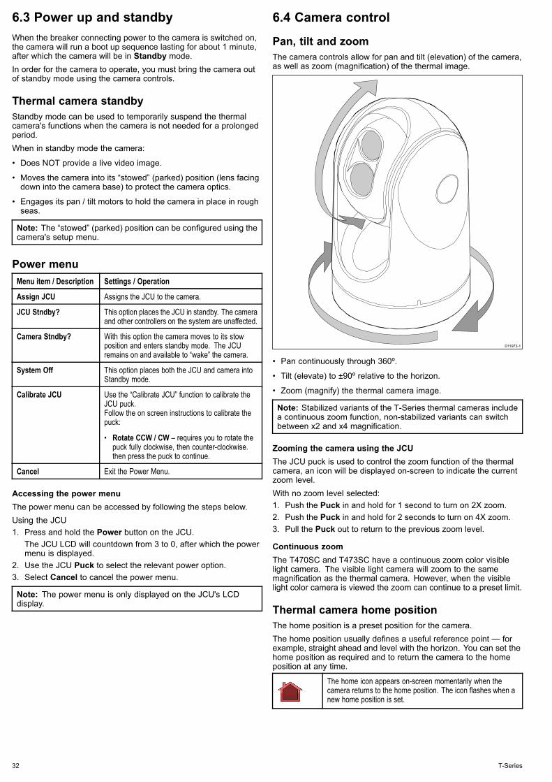
Pan, tilt and zoomThe camera controls allow for pan and tilt (elevation) of the camera,as well as zoom (magnification) of the thermal image.
D11973-1
• Pan continuously through 360º.
• Tilt (elevate) to ±90º relative to the horizon.
• Zoom (magnify) the thermal camera image.
Note: Stabilized variants of the T-Series thermal cameras includea continuous zoom function, non-stabilized variants can switchbetween x2 and x4 magnification.
Zooming the camera using the JCUThe JCU puck is used to control the zoom function of the thermalcamera, an icon will be displayed on-screen to indicate the currentzoom level.With no zoom level selected:1. Push the Puck in and hold for 1 second to turn on 2X zoom.2. Push the Puck in and hold for 2 seconds to turn on 4X zoom.3. Pull the Puck out to return to the previous zoom level.
Continuous zoomThe T470SC and T473SC have a continuous zoom color visiblelight camera. The visible light camera will zoom to the samemagnification as the thermal camera. However, when the visiblelight color camera is viewed the zoom can continue to a preset limit.
Thermal camera home positionThe home position is a preset position for the camera.The home position usually defines a useful reference point — forexample, straight ahead and level with the horizon. You can set thehome position as required and to return the camera to the homeposition at any time.
The home icon appears on-screen momentarily when thecamera returns to the home position. The icon flashes when anew home position is set.
32 T-Series

Thermal camera surveillance modeIn surveillance mode the camera pans left and right continuously.The camera continues to pan until surveillance mode is disabled, orthe JCU (Joystick Control Unit) is used to move the camera. Whenthis occurs the camera does not automatically resume surveillancemode and the mode must be enabled again if required.To enable surveillance mode using only the JCU you must set theUser programmable button to Surveillance mode.
Thermal camera stabilizationThe Raymarine T470SC and T473SC thermal cameras includes amechanical stabilization feature.The mechanical stabilization feature improves image stability bycompensating for vessel motion and keeping the camera aimedat the point of interest. Mechanical stabilization has two aspects:horizontal (azimuth) and vertical (elevation). By default, mechanicalstabilization is set to on, which provides the best on-the-waterperformance particularly when the vessel is underway and travelingon rough water or in swell conditions. You can disable or enablestabilization whenever you want. When you enable full stabilization(horizontal and vertical), the Stabilization On (no wave) icon flashes.It does not display continually, since this is the normal mode ofoperation. If you disable stabilization, the Stabilization Off (wave)icon remains on the screen to make you aware that the motion ofthe vessel can affect the camera performance. This is not a normalmode of operation. Stabilization is automatically turned off whenthe camera is stowed, but the system restores your setting whenthe camera is powered on. You can turn off the horizontal (pan)stabilization while retaining the tilt stabilization by enabling pointmode.
Enabling / Disabling stabilizationStabilization is enabled by default. You can enable or disablestabilization at any time by following the steps below.Using the JCU:1. Press MENU.2. Select System Setup.3. Select Enable Stabilization to turn on mechanical stabilization,
or4. Select Disable Stabilization to turn off mechanical stabilization.5. Press MENU to cancel the on-screen menu.
Thermal camera point modePoint mode is only applicable to thermal cameras which havemechanical stabilization.Enabling point mode only has significance when stabilizationis enabled. Enabling point mode turns off the horizontal (pan)stabilization while retaining the vertical (tilt) stabilization. This canbe helpful when you want to use the thermal camera as an aideto navigation and keep the camera pointing in the same positionrelative to the vessel as it turns. For example, you may havestabilization enabled and have set the camera to point straightahead relative to the front of the vessel. If the vessel is turnedat a sharp angle under these conditions, the camera sensor willnot follow the direction of the vessel. Enabling point mode keepsthe camera in sync with the vessel direction while maintaining astable elevation position. When point mode is enabled, a lock icondisplays. The camera’s azimuth position is now locked to the base.When you disable point mode, the unlock icon displays momentarily.The camera always starts up with point mode disabled.
Enabling / Disabling point modePoint mode is disabled by default. With Stabilization enabled youcan also enable point mode at any time by following the steps below.Using the JCU:1. Press MENU.2. Select Enable Point Mode to turn on point mode, or if already
enabled3. Select Disable Point Mode to turn off point mode.4. Press MENU to cancel the on-screen menu.
6.5 Image adjustments
Thermal camera scene presetsScene presets enable you to quickly select the best image settingfor the current environmental conditions.During normal operation the thermal camera automatically adjustsitself to provide a high-contrast image optimized for most conditions.The Scene presets provide 4 additional settings that may providebetter imagery in certain conditions. The 4 modes are:
Night Running— scene preset mode for night conditions.
Day Running — scene preset mode for daytimeconditions.
Night Docking— scene preset mode for night docking.
Search — scene preset mode for identifying people orobjects in the water.
Although the preset names indicate their intended use, varyingenvironmental conditions might make another setting morepreferable. For example, the night running scene preset might alsobe useful while in a harbor. You may find it beneficial to experimentwith the different scene presets to discover the best preset to usefor different conditions.
Thermal camera color modesA range of color modes are available to help you distinguish objectson-screen in different conditions.Changing the color mode switches the thermal camera imagebetween a greyscale mode and 1 or more color modes. There are5 color modes available.The factory default color mode is red, which may improve your nightvision. This default mode can be changed if required using thecamera's on-screen Video Setup menu.
Note: If you have the Disable Color Thermal Video optionselected in the camera's on-screen Video Setup menu, only 2color modes are available — greyscale and red.
Thermal camera reverse videoYou can reverse the polarity of the video image to change theappearance of objects on-screen.The reverse video option (video polarity) switches the thermalimage from white-hot (or red-hot if the color mode setting is active)to black-hot. The difference between white-hot and black-hot isshown below:
White-hot thermal image.
Black-hot thermal image.
System operation and setup 33

You may find it useful to experiment with this option to find the bestsetting to suit your needs.
Reversing the video polarityTo reverse the polarity of the video image follow the steps below.Using the JCU:1. Press MENU.2. Select Video Setup.3. Select Set Reverse Video4. Select MENU to cancel the on-screen menu.
Thermal and visible-light operation“Dual payload” thermal cameras are equipped with 2 cameras — athermal imaging (infrared) camera and a visible-light camera.
Thermal camera — providesnight-time imagery, basedon temperature differencesbetween objects. Thermalimaging produces a clearimage even in total darkness.
Visible-light camera —provides black and white (orgreyscale) imagery during theday and in low-light conditions.Helps to improve navigationalabilities in low-light conditions;for example during twilighthours when operating alongintercoastal waterways andnear harbor entrances.
Note: The T470SC andT473SC have a colorcamera and continuouszoom lens.
Thermal camera rear view modeThe rear view mode flips the video image horizontally, providing a“mirror image”.This is useful for example in instances where the camera isrear-facing and you are viewing the image on a forward-facingmonitor.
Switching the camera to rearview modeTo switch the camera to rear view mode follow the steps below.Using the JCU1. Press MENU.2. Select System Setup.3. Select Enable Rearview Mode.
When enabled the option is changed to Disable RearviewMode, selecting this will revert back to normal view.
4. Press MENU to cancel the on-screen menu.
6.6 System reset
Resetting the JCUOccasionally it may be necessary to reset the JCU, to do this youcan either power cycle the JCU or follow the steps below:1. Press and hold the SCENE, COLOR and HOME buttons for
1 second.
Resetting the thermal cameraUse this procedure to reset the thermal camera. This will realign thehome and stow positions, for example if they become misaligneddue to heavy weather.1. Press the HOME button 4 times successively to reset the
camera.
Restoring factory defaultsUse this procedure to reset the camera to its factory default settings.With the camera setup menu displayed:1. Select the About/Help menu.2. Select Restore Factory Defaults from the available options.
34 T-Series

6.7 Setup menusThe setup menus provide a range of tools and settings to configurethe thermal camera.The menus can be accessed from any controller on the system. Themenus are overlaid onto the video image.
Note: The on-screen menus only appear on the thermal cameraimage. They are not available when viewing the visible lightimage (on dual payload models).
Menus available
Enable Point Mode /Disable Point Mode
Selecting Enable Point mode will turn point mode on,selecting disable point mode will turn point mode off.Only applies to models with mechanical stabilization.
Video Setup This menu is used to set the video configurationoptions.
Set Symbology Settings associated with the status icons.
User ProgrammableButton
Configure the USER button on the JCU.
System Setup Settings to optimize operation for this particular system/ installation.
About / Help Helpful information and restore to factory defaultssetting.
Exit Cancels on-screen menu.
Video setup menuMenu item / Description Settings / Operation
Set Thermal ColorDefault
This saves the current color setting as the defaultvalue.
Set Reverse VideoDefault
This toggles the infrared image between white-hot(or red-hot if viewing a color image) and black-hot.
Enable / Disable ColorThermal Video
Enable or disable the thermal color palettes:
• Enabled – Greyscale, Red, Sepia, Rainbow andFusion palettes are available.
• Disabled – Only Greyscale and Red palettesare available.
Display Test Pattern Use the display test pattern when setting up thecolor / contrast settings for your particular displayor monitor. You can switch through the 4 testpatterns available.
Exit
Set symbology menuMenu item / Description Settings / Operation
Enable / Disable PC Icon • Enabled – The PC icon is displayed whenever aPC is detected on the network.
• Disabled – The PC icon is not displayed.
Enable / Disable JCUIcon
• Enabled – The JCU icon is displayed whenevera JCU is detected on the network.
• Disabled – The JCU icon is not displayed.
Display All Icons Selecting this menu item enables all availableicons.
Display Minimal Icons Selecting this menu item reduces the icon activity:
• Position, Zoom, Rearview, Pause, Stabilizationdisabled and Point Mode enabled icons areunaffected.
• Home and Scene icons are displayed onlymomentarily.
• Other icons are not shown.
Menu item / Description Settings / Operation
Hide All Icons Selecting this option hides all icons except for:
• Position indicator
• Rearview mode enabled
• Stabilization disabled
• Point mode enabled
Exit Returns to the main menu.
User Programmable Button menuUse this menu to set up the USER button on the JCU.
Menu item / Description USER button operation
Search settings The USER button will set the camera scene toSearch mode.
Switch Thermal / VISVideo(Dual payload modelsonly)
The USER button will switch between Thermal andLow Light camera images.
Hide / Show All Icons The USER button will toggle between Show andHide icon settings.
Reverse Video The USER button will toggle between the White-hotand Black-hot (reverse) thermal image.
Rearview Mode The USER button will toggle Rearview mode onand off.
Surveillance Mode The USER button will toggle Surveillance modeon and off.
Point Mode The USER button will toggle Point Mode on and off.
Exit Returns to the main menu.
System Setup menuMenu item / Description Settings / Operation
Enable / DisableBall-Down Installation
This menu option should be enabled when thecamera is mounted upside down in the “ball-down”configuration.
Enable / DisableTwist-to-Pan mode
This menu option changes the JCU controls panand zoom functions as follows:Enabled— Pan the camera by rotating the Puckclockwise or counterclockwise, zoom in and outby pushing the puck in and pulling it out. (This isdefault operation of the JCU).Disabled— Pan the camera by moving the Puckleft or right, zoom in and out by rotating the Puckclockwise and counterclockwise.
Enable / Disable HighPower Standby
This option controls the amount of power used tohold the camera in position while it is in Standbymode. The enabled setting will consume morepower, but will help ensure that the camera is heldin place in rough seas.
Note: If the camera moves when in standby(due to shock or vibration), then the Positionindicator or Home setting may need realigning(reset the camera to realign).
System operation and setup 35
Menu item / Description Settings / Operation
Enable / Disable HighMotor Torque
This option controls the amount of power used tohold the camera steady when in use. The enabledsetting will consume more power, but help ensurethat the camera is held in place in rough seas.The High Motor Torque mode may be useful forpower boats that operate at higher speeds andexperience high impact environments, and canaccept higher power consumption.
Note: If the camera moves due to shock orvibration, then the Position indicator or Homesetting may need realigning (reset the camerato realign).
Enable / DisableRearview Mode
When this option is enabled the camera image isreversed and you will see a mirror image on thedisplay.
Enable / DisableStabilization
When this option is enabled horizontal and verticalstabilization is turned on. Only applies to T470SCand T473SC.
Set Stow Position This option sets the current position as the Stowposition. The camera moves to the stow positionwhenever it is turned off or put into Standby mode.
Name Camera Use this option to name the camera.
Surveillance mode This options enables you to set the scan width andspeed when in surveillance mode.
Exit Exit to main menu.
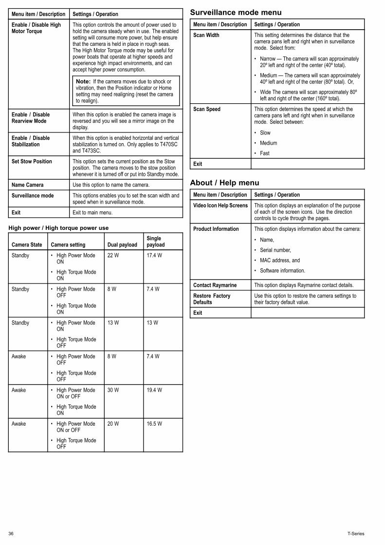
High power / High torque power use
Camera State Camera setting Dual payloadSinglepayload
Standby • High Power ModeON
• High Torque ModeON
22 W 17.4 W
Standby • High Power ModeOFF
• High Torque ModeON
8 W 7.4 W
Standby • High Power ModeON
• High Torque ModeOFF
13 W 13 W
Awake • High Power ModeOFF
• High Torque ModeOFF
8 W 7.4 W
Awake • High Power ModeON or OFF
• High Torque ModeON
30 W 19.4 W
Awake • High Power ModeON or OFF
• High Torque ModeOFF
20 W 16.5 W
Surveillance mode menuMenu item / Description Settings / Operation
Scan Width This setting determines the distance that thecamera pans left and right when in surveillancemode. Select from:
• Narrow — The camera will scan approximately20º left and right of the center (40º total).
• Medium — The camera will scan approximately40º left and right of the center (80º total). Or,
• Wide The camera will scan approximately 80ºleft and right of the center (160º total).
Scan Speed This option determines the speed at which thecamera pans left and right when in surveillancemode. Select between:
• Slow
• Medium
• Fast
Exit
About / Help menuMenu item / Description Settings / Operation
Video Icon Help Screens This option displays an explanation of the purposeof each of the screen icons. Use the directioncontrols to cycle through the pages.
Product Information This option displays information about the camera:
• Name,
• Serial number,
• MAC address, and
• Software information.
Contact Raymarine This option displays Raymarine contact details.
Restore FactoryDefaults
Use this option to restore the camera settings totheir factory default value.
Exit
36 T-Series

Chapter 7: Troubleshooting and support
Chapter contents• 7.1 Thermal camera troubleshooting on page 38
• 7.2 Raymarine customer support on page 39
Troubleshooting and support 37

7.1 Thermal camera troubleshootingProblems with the thermal camera and their possible causes and solutions are described here.
Problem Possible causes Possible solutions
Camera is in Standby mode. The camera will not display video if it is in Standby mode. Use the cameracontrols (either the thermal camera application or JCU) to “wake” thecamera from standby.
Problem with the thermal camera videoconnections.
• Check thermal camera video cables are sound and properly connected.
• Ensure that the video is connected into video input 1 at the multifunctiondisplay or GVM.
• Ensure that the correct video input is selected at the display.
Video not displayed.
Problem with power supply to the cameraor JCU (if used as the primary controller)
• Check the power connections to the camera and JCU / PoE injector (ifused).
• Ensure that the power switch / breaker is on.
• Check the fuse / breaker state.
Cannot control thermal camera fromRaymarine display or keyboard.
Thermal camera application is not running. Ensure the thermal camera application is running on the multifunctiondisplay (as oppose to the video application which does not have cameracontrols).
Check that the controller and thermal camera are correctly connected tothe network. (Note: This may be a direct connection or via a Raymarinenetwork switch.)
Check the status of the Raymarine network switch.
Network problem.
Check that SeaTalkhs / RayNet cables are free from damage.
Control conflict, e.g. caused by multipleusers at different stations.
Ensure that no other controllers are in use at the same time.
Check power / network cabling to the controller and PoE injector (PoE onlyused with optional Joystick Control Unit).
Erratic or unresponsive controls.
Problem with the controller.
Check other controllers if available. If other controllers are operating this willeliminate the possibility of a more fundamental camera fault.
Camera is not a dual payload model. Only “dual payload” (dual lens) thermal cameras support VIS / IR switching.Cannot switch between thermal andvisible (VIS / IR) video image .
VIS / IR cable not connected. Ensure that the VIS / IR cable is connected from the camera to theRaymarine system. (The IR-only cable does not support switching).
Poor quality or faulty video cable. Ensure that the video cable is no longer than necessary. The longer thecable is (or the smaller the wire gauge / thickness), the more severe thelosses become. Use only high quality shielded cable suitable for a marineenvironment.
Noisy image.
Cable is picking up electromagneticinterference (EMI) from another device.
• Ensure you are using a high quality shielded cable.
• Ensure proper cable separation, for example do not run data and powercables in close proximity with each other.
Display brightness is set too low. Use the brightness controls at the display to adjust accordingly.
The contrast or brightness settings in thethermal camera application are set toolow.
Use the appropriate menu in the thermal camera application to adjust thecontrast and brightness of the image.
Image too dark or too light.
The Scene Mode is not appropriate for thecurrent conditions.
A particular environment may benefit from a different Scene Mode setting.For example, a very cold background (such as the sky) could cause thecamera to use a wider temperature range than appropriate. Use the SCENEbutton.
Image freezes momentarily. FFC (Flat Field Correction). The image will pause momentarily on a periodic basis during the Flat FieldCorrection (FFC) cycle. Just prior to the FFC, a small green square willappear in the upper left corner of the screen.
Image is inverted (upside down). Camera “Ball down” setting is incorrect. Ensure that the Ball down setting within the thermal camera system setupmenu is set correctly.
38 T-Series

7.2 Raymarine customer supportRaymarine provides a comprehensive customer support service.You can contact customer support through the Raymarine website,telephone and email. If you are unable to resolve a problem, pleaseuse any of these facilities to obtain additional help.
Web supportPlease visit the customer support area of our website at:www.raymarine.comThis contains Frequently Asked Questions, servicing information,e-mail access to the Raymarine Technical Support Department anddetails of worldwide Raymarine agents.
Telephone and email supportIn the USA:
• Tel: +1 603 324 7900
• Toll Free: +1 800 539 5539
• Email: [email protected]
In the UK, Europe, the Middle East, or Far East:
• Tel: +44 (0)13 2924 6777
• Email: [email protected]
Product informationIf you need to request service, please have the following informationto hand:
• Product name.
• Product identity.
• Serial number.
• Software application version.
You can obtain this product information using the menus within yourproduct.
Troubleshooting and support 39

40 T-Series

Chapter 8: Technical specification
Chapter contents• 8.1 Technical specification on page 42
Technical specification 41
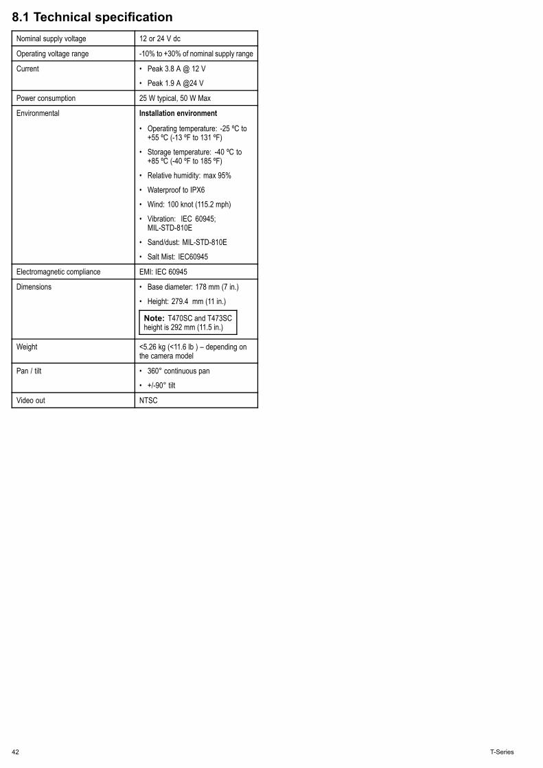
8.1 Technical specificationNominal supply voltage 12 or 24 V dc
Operating voltage range -10% to +30% of nominal supply range
Current • Peak 3.8 A @ 12 V
• Peak 1.9 A @24 V
Power consumption 25 W typical, 50 W Max
Environmental Installation environment
• Operating temperature: -25 ºC to+55 ºC (-13 ºF to 131 ºF)
• Storage temperature: -40 ºC to+85 ºC (-40 ºF to 185 ºF)
• Relative humidity: max 95%
• Waterproof to IPX6
• Wind: 100 knot (115.2 mph)
• Vibration: IEC 60945;MIL-STD-810E
• Sand/dust: MIL-STD-810E
• Salt Mist: IEC60945
Electromagnetic compliance EMI: IEC 60945
Dimensions • Base diameter: 178 mm (7 in.)
• Height: 279.4 mm (11 in.)
Note: T470SC and T473SCheight is 292 mm (11.5 in.)
Weight <5.26 kg (<11.6 lb ) – depending onthe camera model
Pan / tilt • 360° continuous pan
• +/-90° tilt
Video out NTSC
42 T-Series


www.raymarine .com