t04: btl overview (402.8.3) · a. bornheim – t04: btl reference design: overview us-mtd technical...
TRANSCRIPT

T04: BTL Overview (402.8.3) Adi Bornheim US-MTD Technical Review 15-16 November 2018

A. Bornheim – T04: BTL Reference Design: Overview US-MTD Technical Review 2
Introduction to BTL
Technical requirements
Description of mechanics, interfaces, dependencies
Construction, installation, operation, maintenance
Overall schedule and milestones
Major R&D items and path to baseline design
Risks associated with this activity area
Opportunities for value engineering
ESH issues associated with BTL
Summary
Outline

A. Bornheim – T04: BTL Reference Design: Overview US-MTD Technical Review 3
Adi Bornheim, Caltech Roles in international MTD :
Technical Manager BTL Manager of Mechanics & Integration BTL
Roles in USCMS MTD : BTL Manager Manager on BTL engineering
Experience : CMS since 2002 CMS ECAL R&D, installation, commissioning, operation, Higgs and
SM physics Precision timing detector R&D since 2012
Biographical sketch Charge #6

A. Bornheim – T04: BTL Reference Design: Overview US-MTD Technical Review 4
Introduction to BTL Charge #1
BTL technology choice – SiPM/LYSO : Timing performance <20 ps with MIPs in PET crystals. Radiation hardness established at the required level. Extensive experience with SiPM in CMS & LYSO in HEP & PET R&D. Cost effective mass market components

A. Bornheim – T04: BTL Reference Design: Overview US-MTD Technical Review 5
Time resolution 30-40 ps at the start of HL-LHC, <60 ps up to fluences 4000 fb-1. Cover about 36 m2 of area at the outer circumference of
the CMS tracker (TRK). Radiation levels for BTL at the end of HL-LHC : Fluence 1.7 – 2 × 10¹⁴ neq/cm2 , Dose : 16-25 kGy
Maintenance free operation inside the TRK cold volume. Requirement to run SiPMs at -30 C to limit dark count rate (DCR).
Design compatible with installation schedule of TRK.
BTL Design and Performance Specification Charge #1,5

A. Bornheim – T04: BTL Reference Design: Overview US-MTD Technical Review 6
BTL Layout
BTL will be attached to the inner wall of the Tracker Support Tube (TST). Cold volume shared with TRK.
BTL Segmentation driven by SiPM Dark Count Rate (DCR) :
72 trays (36 in ϕ × 2 in η) Tray : 250 x 18 x 2.5 cm
500k channels
2 trays in eta

A. Bornheim – T04: BTL Reference Design: Overview US-MTD Technical Review 7
BTL Tray
BTL trays are 2500x185x20 mm in size, weight <20 kg. Three layer design :
Cooling plate : Aluminum plate with SS CO2 cooling pipe Front End electronics : ASIC boards, Concentrator Cards, powering Sensor board : LYSO/SiPM on sensor mother board
Supported by rails from the inner wall of the TST.
Cooling plate
Front End
Sensor board
TST
TRK volume
A. Bornheim – T04: BTL Reference Design: Overview US-MTD Technical Review 8
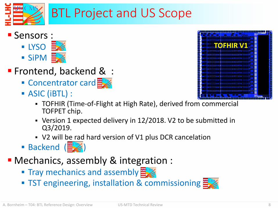
Sensors : LYSO SiPM
Frontend, backend & : Concentrator card ASIC (iBTL) :
TOFHIR (Time-of-Flight at High Rate), derived from commercial TOFPET chip.
Version 1 expected delivery in 12/2018. V2 to be submitted in Q3/2019.
V2 will be rad hard version of V1 plus DCR cancelation Backend ( )
Mechanics, assembly & integration : Tray mechanics and assembly TST engineering, installation & commissioning
BTL Project and US Scope
TOFHIR V1

A. Bornheim – T04: BTL Reference Design: Overview US-MTD Technical Review 9
BTL LYSO LYSO crystals are widely used in industry for radiation
detectors. Subject to HEP specific R&D since many years. Optimization of BTL LYSO sensors (US scope) mostly on
form factor, packaging and optical coupling. LYSO procurement plan being worked out b iBTL. See presentation from M. Lucchini BTL LYSO tiles BTL LYSO bars

A. Bornheim – T04: BTL Reference Design: Overview US-MTD Technical Review 10
BTL SiPM SiPM are key to detector performance. R&D to reduce dark count rates (DCR). Focus on commercial form factor to
benefit from lower prices. SiPM R&D core to US program, eg. HCAL. Sensor choice and qualification, QAQC
are US scope. See presentation from M. Wayne.
HCAL SiPM array
BTL tile sensor board prototype
SiPM Dark Current (DCR)
SiPM PDE vs OV

A. Bornheim – T04: BTL Reference Design: Overview US-MTD Technical Review 11
BTL Front End electronics based on TOFHIR ASIC, derived from commercial project (not US scope). Concentrator card (US scope) interfaces between ASIC
boards and power and data services. See presentation from Y. Maravin
BTL FE - Concentrator Card

A. Bornheim – T04: BTL Reference Design: Overview US-MTD Technical Review 12
BTL Assembly Model BTL assembly model utilizes outsourcing industry, trays
assembled in three assembly centers (2 US, 1 IT). Delivery to CERN for integration into the TST. See presentation by A. Bornheim
A. Bornheim – T04: BTL Reference Design: Overview US-MTD Technical Review 13
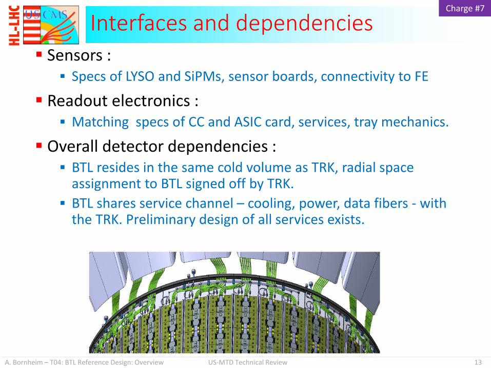
Sensors : Specs of LYSO and SiPMs, sensor boards, connectivity to FE
Readout electronics : Matching specs of CC and ASIC card, services, tray mechanics.
Overall detector dependencies : BTL resides in the same cold volume as TRK, radial space
assignment to BTL signed off by TRK. BTL shares service channel – cooling, power, data fibers - with
the TRK. Preliminary design of all services exists.
Interfaces and dependencies Charge #7
A. Bornheim – T04: BTL Reference Design: Overview US-MTD Technical Review 14
Integration of the BTL into the TST will happen at the Tracker Integration Facility at CERN. Once integrated, BTL will follow along with the TRK
integration into CMS at P5. Operationally BTL and TRK will largely be separated
(powering, cooling on/off cycles), but will share common cold volume. Thermal cycling to anneal SiPMs synchronized with TRK.
As TRK, BTL will not be accessible for maintenance after installation. Robust design and extensive QC.
Calibration and monitoring of BTL : In-situ with tracks, following experience with CMS ECAL in
Phase I. Monitoring with LYSO natural radioactivity.
Construction, Operation, Maintenance Charge #2

A. Bornheim – T04: BTL Reference Design: Overview US-MTD Technical Review 15
R&D on SiPMs to find best solution for maximal PDE at low power consumption, low DCR and low price. LYSO R&D very limited, started investigating the
commercialization process. Radiation tolerance has been demonstrated in earlier R&D.
Concentrator Card development ongoing. Assembly procedure conceptual design, engineering
work started. Mechanical interfaces conceptual design exists,
engineering design starting. More details in the respective talks.
R&D plan for US scope Charge #3
A. Bornheim – T04: BTL Reference Design: Overview US-MTD Technical Review 16
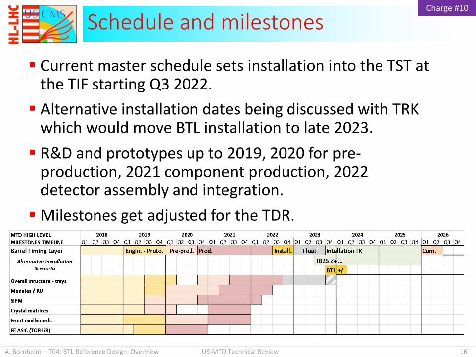
Current master schedule sets installation into the TST at the TIF starting Q3 2022. Alternative installation dates being discussed with TRK
which would move BTL installation to late 2023. R&D and prototypes up to 2019, 2020 for pre-
production, 2021 component production, 2022 detector assembly and integration. Milestones get adjusted for the TDR.
Schedule and milestones Charge #10

A. Bornheim – T04: BTL Reference Design: Overview US-MTD Technical Review 17
Project governed by Fermilab Risk Management plan. Risk workshop with external reviewers conducted.
Risks Charge #4

A. Bornheim – T04: BTL Reference Design: Overview US-MTD Technical Review 18
Value Engineering seeks to maintain same functionality at reduced cost either up front or during operations Development of BTL sensors from LYSO crystals and
SiPMs utilizing commercially available components. SiPM expertise from HCAL R&D and Phase I upgrade. LYSO performance and radiation hardness qualification
from previous Phase II R&D. Elements developed as common CERN projects such as
ATCA crates and communication standards, and FPGA-controlled boards for the backend and trigger. Using assembly procedures developed by CALICE
collaboration, utilizing standard industry procedures such as pick-an-place circuit board assembly technology.
Opportunities for Value Engineering Charge #5

A. Bornheim – T04: BTL Reference Design: Overview US-MTD Technical Review 19
All ES&H aspects of the HL LHC CMS Detector Upgrade Project will be handled in accordance with the Fermilab Integrated Safety Management approach, and the rules and procedures laid out in the Fermilab ES&H Manual (FESHM) The current construction plan involves no materials of identified
environmental risk : cooling plant is based on CO2
Detector will be operated in a refrigerated mode (-30°C), similar to TRK. Standard operational procedures will be developed and
documented to allow safe operation R&D and some production testing will involve the use of
gamma, neutron, and proton radiation. These tests will be performed at commonly-used radiation and
test beam facilities
Environmental, Safety and Health Charge #9

A. Bornheim – T04: BTL Reference Design: Overview US-MTD Technical Review 20
The BTL detector design is well advanced as documented in the CDR. The TDR is being written by the CMS collaboration. Strong project team is identifying and documenting
risks, interfaces, and structuring the project appropriately in the P6 system to manage the project appropriately in the construction phase. US CMS plays a crucial roles in the MTD project.
Summary

A. Bornheim – T04: BTL Reference Design: Overview US-MTD Technical Review 21
Backup