t101-04 & t202-03 service manualproductload.johnsonfit.com/inc/uploaded_media/549b...8 chapter...
TRANSCRIPT

1
T101-04 & T202-03 Service Manual

2

3

4
Contents
CHAPTER 1: SERIAL NUMBER LOCATION .................................................................................................. 6
CHAPTER 2: PREVENTATIVE MAINTENANCE
2.1 Preventative Maintenance ....................................................................................................................... 8
2.2 Tension and Centering the Running Belt ............................................................................................... 10
CHAPTER 3: CONSOLE INSTRUCTION
3.1 Console Overview .................................................................................................................................. 11
3.1.1 T101-04 Console Overview ................................................................................................................ 11
3.1.2 T202-03 Console Overview ................................................................................................................ 12
3.2 Display Window Indication ..................................................................................................................... 13
3.3 Getting Started & Selecting a Workout .................................................................................................. 15
3.4 Program Information .............................................................................................................................. 16
CHAPTER 4: ENGINEERING MODE
4.1 Engineering Mode .................................................................................................................................. 20
4.2 Engineering Mode Overview .................................................................................................................. 21
CHAPTER 5: TROUBLESHOTING
5.1 Electrical Diagram ............................................................................................................................... 23
5.2 MCB Wiring Instructions ...................................................................................................................... 25
5.3.1 Troubleshooting - No Power To The Console .................................................................................. 27
5.3.2 Troubleshooting - No Function For Safety Key .............................................................................. 28
5.3.3 Troubleshooting - No Response For Machine(Console & Motor) ....................................................... 29
5.3.4 Troubleshooting - Incline Motor Issues ............................................................................................ 30
5.3.5 Troubleshooting - Noise Issues ........................................................................................................ 31
5.3.6 Troubleshooting - Speaker / Audio Issues ....................................................................................... 33
5.3.7 Troubleshooting - Heart Rate Function Issues................................................................................. 35

5
CHAPTER 6: PART REPLACEMENT GUIDE
6.1 Motor Cover Replacement .................................................................................................................. 36
6.2 Rear Roller Replacement .................................................................................................................... 37
6.3 Side Rail Replacement ........................................................................................................................ 38
6.4 Running Deck Replacement ................................................................................................................ 39
6.5 Front Roller Replacement ................................................................................................................... 40
6.6 Running Belt Replacement .................................................................................................................. 41
6.7 Motor Control Board (MCB) Replacement .......................................................................................... 42
6.8 Motor Replacement ............................................................................................................................. 43
6.9 Drive Belt Replacement ....................................................................................................................... 44
6.10 Incline Motor Replacement ................................................................................................................ 45
6.11 Console Replacement ....................................................................................................................... 46
6.12 Heart Rate Board Service ................................................................................................................. 47

6
CHAPTER 1: Serial Number Location 1
1.1 SERIAL NUMBER LOCATION
1.1.1 T101-04

7
CHAPTER 1: Serial Number Location 1
1.1.2 T202-03

8
CHAPTER 2: Preventative Maintenance
2.1 PREVENTATIVE MAINTENANCE
Preventative maintenance is the key to smoothly operating equipment, as well as keeping the user’s liability to a minimum.
Equipment needs to be inspected at regular intervals. Defective components must be replaced immediately. Improperly
working equipment must be kept out of use until it is repaired. Ensure that any person(s) making adjustments or
performing maintenance or repair of any kind is qualified to do so.
EVERY DAY (DAILY)
Clean and inspect, following these steps:
• Turn off the treadmill with the ON / OFF switch, then unplug the power cord at the wall outlet.
• Wipe down the running belt, deck, motor cover, and console casing with a damp cloth. Never use solvents, as they can
cause damage to the treadmill.
• Inspect the power cord. If the power cord is damaged, stop using and contact Customer Technical Support.
• Make sure the power cord is not underneath the treadmill or in any other area where it can become pinched or cut.
• Check the tension and alignment of the running belt. Make sure that the treadmill belt will not damage any other
components on the treadmill by being misaligned.
• If any labels are damaged or illegible, contact Customer Technical Support for replacements.
EVERY WEEK (WEEKLY)
Clean underneath the treadmill following these steps:
• Turn off the treadmill with the ON / OFF switch, then unplug the power cord at the wall outlet.
• Fold the treadmill into the upright position, making sure that the lock latch is secured.
• Move the treadmill to a remote location.
• Wipe or vacuum any dust particles or other objects that may have accumulated underneath the treadmill.
• Return the treadmill to its previous position.
EVERY MONTH - IMPORTANT!
• Turn off the treadmill with the ON / OFF switch, then unplug the power cord at the wall outlet.
• Inspect all assembly bolts of the machine for proper tightness.
• Remove the motor cover. Wait for ALL display screens to be off.
• Clean the motor and lower board area to eliminate any lint or dust particles that may have accumulated. Failure to do
so may result in premature failure of key electrical components.
• Vacuum and wipe down the belt with a damp cloth. Vacuum any black / white particles that may accumulate around
the unit. These particles may accumulate from normal treadmill use.

9
CHAPTER 2: Preventative Maintenance
2.1 PREVENTATIVE MAINTENANCE-CONTINUED
EVERY 6 MONTHS OR 150 MILES
It is necessary to lubricate your treadmill running deck every
six months or 150 miles (240 kilometers) to maintain optimal
performance. Once the treadmill reaches 150 miles (240
kilometers), the console will display the message “LUBE” or
“LUBE BELT”. The treadmill will not operate while the
message is showing. Hold ‘STOP’ for 5 seconds to suspend
message for 5 miles.
Your treadmill came with a bottle of lubricant which can be
used for two applications.
● Turn off the treadmill with the on/off switch, then unplug the
power cord at the wall outlet.
● Loosen both the rear roller bolts. (For best results, place
two removable marks on both sides of the frame and note
roller position). Once the belt is loosened, take the bottle of
lubricant and apply it to the entire top surface of the
running deck. Tighten both rear roller bolts (matching up the marks for proper position) to original position. After you
have applied lubricant, plug in the power cord, insert the safety key, start the treadmill and walk on the belt for two
minutes to spread the lubricant.
● Lubricate the air shocks with Teflon based spray.
● When lubrication is complete, hold “elevation ▲ & Stop” both keys 5 seconds then the message will be clean.

10
CHAPTER 2: Preventative Maintenance
2.2 TENSIONING & CENTERING THE RUNNING BELT
If you can feel a slipping sensation when running on the treadmill, the running belt must be tightened. In most cases, the
belt has stretched from use, causing the belt to slip. This is a normal and common adjustment. To eliminate this slipping,
turn the treadmill off and tension both the rear roller bolts using the supplied Allen wrench, turning them ¼ turn to the right
as shown. Turn the treadmill on and check for slipping. Repeat if necessary, but never turn the roller bolts more than ¼
turn at a time. Belt is properly tensioned when the slipping sensation is gone.
The running belt has been properly adjusted at the factory before it was shipped. At times the belt can move off-center
during shipment. Before operating the treadmill, make sure the belt is centered and remains centered to maintain smooth
operation.
If the running belt is too far to the right side: With the treadmill
running at 1 mph, turn the left adjustment bolt counter-clockwise
¼ turn at a time (using the supplied Allen wrench). Check the belt
alignment. Allow belt to run a full cycle to gauge if more
adjustment is needed. Repeat if necessary, until the belt remains
centered during use.
If the running belt is too far to the left side: With the treadmill
running at 1 mph, turn the right adjustment bolt counter-clockwise
¼ turn at a time (using the supplied Allen wrench). Check the belt
alignment. Allow belt to run a full cycle to gauge if more
adjustment is needed. Repeat if necessary, until the belt remains
centered during use.

11
. CHAPTER 3: Console Instruction
3.1 CONSOLE OVERVIEW
3.1.1 T101-04 Console Overview
Note: There is a thin protective sheet of clear plastic on the overlay of the console that should be removed before use.
A) LCD display window: time, distance, calories, incline, speed, heart rate and fan.
B) Programming keys: Used to cycle through programs and user setup.
C) Enter: used to confirm selection.
D) Energy Saver indicator: indicates if machine is in Energy Saver mode.
E) Program keys: press to select workout.
F) Audio in jack: plug your media player into the console using the included audio adaptor cable.
G) Volume: used to adjust volume up or down.
H) Fan key: press to turn fan on and off.
I) Incline quick keys: used to reach desired incline quickly.
J) Incline keys: used to adjust incline level.
K) Speed quick keys: used to reach desired speed quickly.
L) Speed keys: used to adjust speed level.
M) Reading rack: holds reading material.
N) Start / Pause: used to start workout, pause workout, and restart after pause.
O) Stop / Hold to reset: used to stop machine and also will reset machine when held down.
P) Safety key: enables treadmill when safety key is inserted.
Q) Speakers: plays music through speakers when connected to your media player.
12
CHAPTER 3: Console Instruction
O) Stop / Hold to reset: used to stop machine and also will reset machine when held down.
P) Safety key: enables treadmill when safety key is inserted.
Q) Speakers: plays music through speakers when connected to your media player.
R) Storage pockets: holds personal items, e.g. water bottle, brought with you.
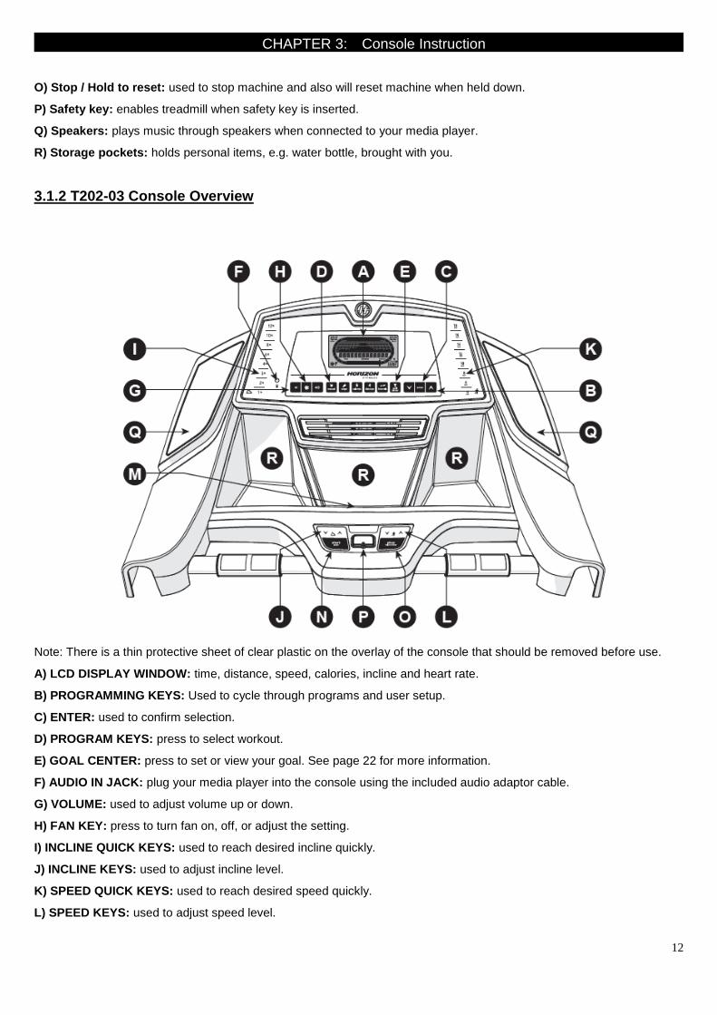
3.1.2 T202-03 Console Overview
Note: There is a thin protective sheet of clear plastic on the overlay of the console that should be removed before use.
A) LCD DISPLAY WINDOW: time, distance, speed, calories, incline and heart rate.
B) PROGRAMMING KEYS: Used to cycle through programs and user setup.
C) ENTER: used to confirm selection.
D) PROGRAM KEYS: press to select workout.
E) GOAL CENTER: press to set or view your goal. See page 22 for more information.
F) AUDIO IN JACK: plug your media player into the console using the included audio adaptor cable.
G) VOLUME: used to adjust volume up or down.
H) FAN KEY: press to turn fan on, off, or adjust the setting.
I) INCLINE QUICK KEYS: used to reach desired incline quickly.
J) INCLINE KEYS: used to adjust incline level.
K) SPEED QUICK KEYS: used to reach desired speed quickly.
L) SPEED KEYS: used to adjust speed level.
13
CHAPTER 3: Console Instruction
M) READING RACK: holds reading material.
N) START / PAUSE: used to start workout, pause workout, and restart after pause.
O) STOP / HOLD TO RESET: used to stop machine and also will reset machine when held down.
P) SAFETY KEY: enables treadmill when safety key is inserted.
Q) SPEAKERS: plays music through speakers when connected to your media player.
R) STORAGE POCKETS: holds personal items, e.g. water bottle, brought with you.
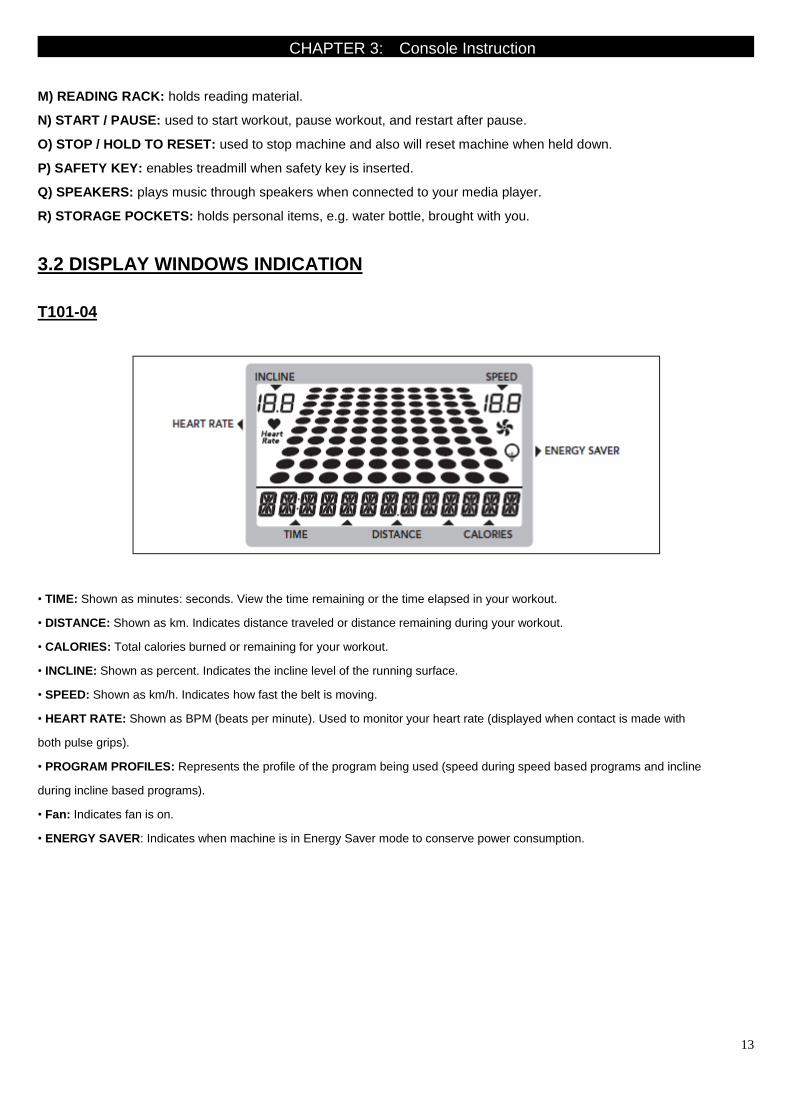
3.2 DISPLAY WINDOWS INDICATION
T101-04
• TIME: Shown as minutes: seconds. View the time remaining or the time elapsed in your workout.
• DISTANCE: Shown as km. Indicates distance traveled or distance remaining during your workout.
• CALORIES: Total calories burned or remaining for your workout.
• INCLINE: Shown as percent. Indicates the incline level of the running surface.
• SPEED: Shown as km/h. Indicates how fast the belt is moving.
• HEART RATE: Shown as BPM (beats per minute). Used to monitor your heart rate (displayed when contact is made with
both pulse grips).
• PROGRAM PROFILES: Represents the profile of the program being used (speed during speed based programs and incline
during incline based programs).
• Fan: Indicates fan is on.
• ENERGY SAVER: Indicates when machine is in Energy Saver mode to conserve power consumption.

14
CHAPTER 3: Console Instruction
T202-03
• TIME: Shown as minutes: seconds. View the time remaining or the time elapsed in your workout.
• DISTANCE: Shown as km. Indicates distance traveled or distance remaining during your workout.
• CALORIES: Total calories burned or remaining for your workout.
• INCLINE: Shown as percent. Indicates the incline level of the running surface.
• SPEED: Shown as km/h. Indicates how fast the belt is moving.
• HEART RATE: Shown as BPM (beats per minute). Used to monitor your heart rate (displayed when contact is made with
both pulse grips).
• PROGRAM PROFILES: Represents the profile of the program being used (speed during speed based programs and
incline during incline based programs).
• FAN: Indicates fan setting (low, medium, high).
• TRACK: Follows progress around a simulated track. Segments light up with every 12.5 meters completed. One lap
around the track is 400 meters.

15
CHAPTER 3: Console Instruction
3.3. GETTING STARTED & SELECTING A WORKOUT
T101-04 GETTING STARTED
1) Check to make sure no objects are placed on the belt that will hinder the movement of the treadmill.
2) Plug in the power cord and turn the treadmill ON.
3) Stand on the side rails of the treadmill.
4) Attach the safety key clip to part of your clothing making sure that it is secure and will not become detached during
operation.
5) Insert the safety key into the safety keyhole in the console.
6) Set user weight using and press ENTER.
7) You have two options to start your workout:
A) QUICK START
Simply press the START key to begin working out.
Time, distance, and calories will all count up from zero. OR...
B) SELECT A PROGRAM
1) Press desired WORKOUT BUTTON and press ENTER.
2) Select workout goal level or program using and press ENTER.
3) Set workout program information using (see program information for necessary settings) and press ENTER after each
selection.
4) Press START to begin workout.
NOTE: You can adjust the speed and incline during your workout.
FINISHING YOUR WORKOUT
When your workout is complete, the console will display “workout complete” and beep. Your workout information will stay
displayed on the console for 30 seconds and then reset.
TO RESET THE CONSOLE
Hold STOP key for 3 seconds.
TO CLEAR CURRENT SELECTION
To clear the current program selection or screen, hold the stop button for 3 seconds.
T202-03 GETTING STARTED
1) Check to make sure no objects are placed on the belt that will hinder the movement of the treadmill.
2) Plug in the power cord and turn the treadmill ON.
3) Stand on the side rails of the treadmill.
4) Attach the safety key clip to part of your clothing making sure that it is secure and will not become detached during
operation.

16
CHAPTER 3: Console Instruction
5) Insert the safety key into the safety keyhole in the console.
6) Select User 1, User 2, or Guest using and press ENTER.
7) Set User Weight using and press ENTER.
8) You have two options to start your workout:
A) QUICK START UP
Simply press the START key to begin working out. Time, distance, and calories will all count up from zero. OR...
B) SELECT A WORKOUT
1) Press desired WORKOUT BUTTON and press ENTER.
2) Select workout goal level or program using and press ENTER.
3) Set workout program information using ( see program information for necessary settings) and press ENTER after
each selection.
4) Press START to begin workout.
NOTE: You can adjust the speed and incline during your workout.
FINISHING YOUR WORKOUT
When your workout is complete, the console will display “workout complete” and beep. Your workout information will stay
displayed on the console for 30 seconds and then reset.
TO RESET THE CONSOLE
Hold STOP key for 3 seconds.
3.4. PROGRAM INFORMATION
T101-04
MANUAL: Adjust your speed and incline manually during your workout. User sets time, starting speed and incline.
\
STEPS: Promotes healthy activity with 2 step-based workouts calculated using average stride length. Choose
from 5000 and 10,000 step workouts. User sets starting speed and incline.
CALORIES: Set goals for burning calories with 3 workouts. Choose from 100, 300 and 500 calorie burn workouts.
User inputs weight and sets starting speed and incline. Calories burned are calculated using weight input with the
speed and incline of the workout
.
DISTANCE: Push yourself and go further during your workout with 2 distance workouts. Choose from 5k, 10k. User
sets starting speed and incline.
INTERVALS: An effective fat-burning workout that helps you get improve your fitness level. Choose from Speed

17
CHAPTER 3: Console Instruction
Intervals and Peak Intervals. User sets time and starting level.
T202-03
MANUAL: Adjust your speed and incline manually during your workout. User sets time, starting speed and
incline.
\
STEPS: Promotes healthy activity with 10 step-based workouts calculated using average stride length. Choose from
1000, 2000, 3000, 4000, 5000, 6000, 7000, 8000, 9000 and 10,000 step workouts. User sets starting speed
and incline

18
CHAPTER 3: Console Instruction
.
CALORIES: Set goals for burning calories with six workouts. Choose from 100, 200, 300, 400, 500, and 600
calories burn workouts. User sets starting speed and incline. Calories burned are calculated using weight input by
user with the speed and incline of workout.
.
DISTANCE: Push yourself and go further during your workout with 10 distance workouts. Choose from 1 mile, 2
miles, 5k, 5 miles, 10k, 8 miles, 15k, 10 miles, 20k, and half marathon goals. User sets starting speed and incline.
INTERVALS: An effective fat-burning workout that helps you get improve your fitness level. Choose from Speed
Intervals, Peak Intervals, and Endurance Intervals workouts. User sets time and starting level.
USING YOUR MEDIA PLAYER
1) Connect the included audio adaptor cable to the audio in jack on the left of the console and the headphone jack
on your media player.
2) Use your media player buttons to adjust song settings.
3) Remove the audio adaptor cable when not in use.
19
CHAPTER 3: Console Instruction
ENERGY SAVER (STANDBY MODE)
This machine has a special feature called Energy Saver™ mode. This mode is NOT automatically activated. When Energy
Saver mode is activated, the display will automatically enter standby mode (Energy Saver mode) after 15 minutes of
inactivity. This feature saves energy by disabling most power to the machine until a key is pressed on the console. This
feature can be turned on or off in the engineering menu.
To enter the engineering menu, press and hold the INCLINE key and SPEED key for 3-5 seconds. Use the keys
to navigate through the menu to ENG 3. Press ENTER to select. Press ENTER to navigate to P5 in the ENG3 menu. Use
the keys to select ENRGY SVE ON or OFF. Press and hold STOP for 3-5 seconds to exit ENG 3. Press and hold STOP
again for 3-5 seconds to exit the engineering menu.

20
CHAPTER 4: Engineering Mode
4.1 ENGINEERING MODE

21
CHAPTER 4: Engineering Mode
4.2 ENGINEERING MODE OVERVIEW
T101-04

22
CHAPTER 4: Engineering Mode
T202-03

23
CHAPTER 5: Troubleshooting
5.1 ELECTRIC DIAGRAM
T101-04

24
CHAPTER 5: Troubleshooting
T202-03

25
CHAPTER 5: Troubleshooting
5.2 TROUBLESHOOTING-MCB WIRING INSTRUCTIONS
T101-04 MCB wiring instructions
CN1------- AC motor cable socket
CN2------- AC power cable socket
CN3------- Elevation motor cable socket
CN4------- Console set cable socket
CN5------- Transfer board

26
CHAPTER 5: Troubleshooting
T202-03 MCB wiring instructions
CN1------- Power light
CN2------- AC power cable socket
CN3------- Elevation motor cable socket
CN4------- Speed sensor cable socket
CN5------- Error light, near the chip
CN6----- Console set cable socket
CN7-------Transfer board

27
CHAPTER 5: Troubleshooting
5.3 TROUBLESHOOTING – NO POWER TO THE CONSOLE
NO POWER TO THE CONSOLE
1) SYMPTOM:
a. Turn on the power switch, but the console will not light up.
2) SOLUTION:
a. Check if the power cord connected well.
- If the power cord connected well but console doesn’t turn on, try another one.
b. Check if the outlet is well.
- If no, please try another functional outlet.
c. Check if the MCB has power. There is a red power LED on the MCB that should be lit.
d. If the MCB does not have power, check the connection of the power wiring from the power receptacle to the MCB.
Use a multi-meter to measure AC1 & AC2, AC voltage shall be same as local’s standard voltage (110V-240V)
- If AC voltage value is standard, replace the MCB as it shall be defective.
e. If the MCB does have power, check the connection of the console cable wire at the MCB and UCB.
- Remove the console cable from MCB, and use a multi-meter to measure the DC voltage between the “GND pin”
(Pin 1&2) and the ”+ 12V Pin” (Pin7 & 8)-. DC output is normally around DC 12V. If no output, replace the MCB.
- If output is around DC 12V, check the console cable. If it is defective, replace the console cable.
- If the console cable connections are all good, replace the PCB.

28
CHAPTER 5: Troubleshooting
5.4 TROUBLESHOOTING – NO FUNCTION FOR SAFETY KEY
NO FUNCTION FOR SAFETY KEY
1) SYMPTOM:
a. The safety key inserted in console, but display window still shows “safety key off”.
2) SOLUTION:
a. Check if the safety key totally inserted in the console.
- If no, take off and insert again.
b. Check if the safety key oxidized or not which will affect the conduction.
- If yes, please change a new one.
c. If the safety key is function, check the safety key sensor wires in console.
- Suggest to re-connect the wires or to change new wires.

29
CHAPTER 5: Troubleshooting
5.5 TROUBLESHOOTING – NO RESPONSE FOR MACHINE (CONSOLE&MOTOR)
THE POWER IS ON, BUT MACHINE HAS NO RESPONSE
1) SYMPTOM:
a. The power is on and the console lights up, but the treadmill does not run when keys are pressed.
2) SOLUTION:
a. Check if the console beeps when all keys are pressed. If no, replace the keypads.
b. Enter Engineering Mode, and scroll to ENG 1 (Hardware Test).Press the key “ENTER” first and then the
key ”START”.
- When press the key “SPEED + / -“, if the data on windows “TIME” & “DISTANCE” is changed, the console is ok.
If not, replace the PCB.
c. Turn off the power switch, and open the motor upper cover. Remove the red & black wires of motor from the MCB,
and use a multi-meter to measure the resistance of drive motor.
If the resistance is bigger than 10 Ω, the drive motor is defective. Replace the drive motor.
If the resistance is lower than 10 Ω, the drive motor is ok. Then,
- Check the connection of the speed sensor (encoder disk group) at the MCB.
- Remove the speed sensor from the motor and clean it, then re-test.
- If the speed sensor is clean and has a good connection but still will not operate, replace the speed sensor.
- Replace the MCB as the last step if machine does still not run after to take above actions.

30
CHAPTER 5: Troubleshooting
5.6 TROUBLESHOOTING - INCLINE MOTOR ISSUES
INCLINE MOTOR ISSUES
1) SYMPTOM:
a. The incline motor does not lift up or down.
2) SOLUTION:
a. Enter Engineering Mode, and scroll to ENG 1 (Hardware Test). Press the key “ENTER” first and then the
key ”START”.
- Press the key “INCLINE ▲/▼”.
If can hear beeps from two relays at the MCB, the MCB is ok. Then check the connection of the elevation
motor at the MCB first, try to unplug and re-plug these two pins. If cannot resolve the issue, replace the elevation
motor.
If there is no beeps from these two relays, MCB is defective and replace the MCB.

31
CHAPTER 5: Troubleshooting
5.7 TROUBLESHOOTING - NOISE ISSUES
NOISE ISSUES
1) SYMPTOM:
a. Thumping noise twice per rotation on new machine.
b. Rubbing / grinding noise.
c. High pitched “bell-like” sound from under the motor cover.
d. Banging or clunking sound.
e. Slapping / thunking / squeaking sound with each footstep.
f. Rubbing sound underneath the treadmill.
g. Squeaking noise when raising / lowering the deck into storage positions.
h. Squeaking / grinding noise when using elevation.
2) SOLUTION:
a. This noise is from the roller or running belt.
- If this is a new unit, some noise is normal as the running belt forms around the rollers.
- Check that the belt is centered and tensioned correctly.
- Remove and clean the rollers if needed.
- Replace the rollers or running belt as needed.
b. This sound is likely a moving component.
- Remove the motor cover and check the drive belt for alignment and make sure it is not slipping or is frayed / cut
in any way. Replace the drive belt if needed.
- Make sure the optic disk on the motor is not rubbing the speed sensor.
- Turn the motor by hand to see if motor brushes or bearings are rubbing. Replace the motor
if needed.
- Check the front and rear rollers, replace if needed.
c. This sound is likely caused by the optic disk.
- Check that the optic disk is tight on the motor and not rubbing the speed sensor.
d. The sound is likely due to the unit not being level.
- Check that all levelers are touching the ground.
- Move the treadmill to another flat surface.
e. This sound is from the running deck / belt.

32
CHAPTER 5: Troubleshooting
5.7 TROUBLESHOOTING - NOISE ISSUES-CONTINUED
- Check that the running deck is tightly attached to the frame.
- Check the deck shocks for deterioration or crumbling. Replace if needed.
- Check to see if the air shock is making this noise, lubricate or replace if needed.
f. This sound is likely due to the air shock.
- Lubricate or replace the air shock as needed.
g. This sound is likely from the incline motor.
- Check that the incline motor connection points include Teflon washers.
- Lubricate the incline motor worm screw and connection points with grease.
- Replace the incline motor.
C

33
CHAPTER 5: Troubleshooting
5.8 TROUBLESHOOTING - SPEAKER / AUDIO ISSUES
Speaker / Audio Issues
1) SYMPTOM:
a. No sound through the speakers but headphones work.
b. No sound through headphones but the speakers work.
c. No sound through speakers or headphones.
d. IPod not charging.
e. Speakers buzzing.
f. Sound from one speaker only.
g. Shock from headphones.
2) SOLUTION:
a. One of the speaker boards has a bad connection or is faulty.
- Check the connection of the wires going from the speakers to the speaker power board.
- Check the connection of the wires going from the speaker power board to the amp board.
- Check the connection of the wires going from the amp board to the console.
- Replace the speaker or amp boards and wiring.
- Replace the speakers.
- If the speaker board, amp board, wiring, and speakers do not solve the issue,
replace the console.
b. There is a bad connection between the headphones and the console.
- Verify the connection of the music player to the dock or audio adaptor cable.
- Verify the audio adaptor cable connection at the console.
- Replace the headphone jack.
- Replace the audio adaptor cable.
c. There is a bad connection between one of the audio boards and the console.
- Verify the connection of the music player to the dock or audio adaptor cable.
- Verify the audio adaptor cable connection at the console.
- Replace the audio adaptor cable.
- Replace the console.
d. Speakers are not getting a clear signal through the speaker wires.
- Check the speaker wire connections.

34
CHAPTER 5: Troubleshooting
5.8 TROUBLESHOOTING - SPEAKER / AUDIO ISSUES-CONTINUED
- Replace the speaker wiring.
- Replace the speakers.
e. The speaker or speaker wiring is bad.
- Check the speaker wire connections.
- Switch the speaker connections from one speaker to the other to see if sound switches sides.
- If the sound does not switch sides, replace the speaker board.
- If the sound does switch sides, replace the speaker and speaker wires.
f. Grounding issue.
- Try a different set of headphones.
- Check the grounding of the console.

35
CHAPTER 5: Troubleshooting
5.9 TROUBLESHOOTING- HEART RATE FUNCTION ISSUE
Heart rate function does not work or is reading incorrectly
1) SYMPTOM:
a. The chest strap being used is not making good contact with the user's chest.
b. The chest strap is at a low battery status.
c. The chest strap is damaged.
d. The HR grips are damaged.
e. Heart rate board damaged
f. The UCB is damaged.
2) SOLUTION:
a. Re-center the chest strap below the user's pectoral muscle and check again.
b. Replace the battery in the chest strap.
c. Replace the chest strap.
d. If there is no HR present, replace the HR grips.
e. If there is a HR present but it is much higher than normal, replace the HR board.
f. If replacing the HR grips and board does not resolve the issues, replace the console

36
CHAPTER 6: PART REPLACEMENT GUIDE
6.1 MOTOR COVER REPLACEMENT
1) Remove the 2 screws holding the motor cover to the frame (Figures A&B).
2) The cover is secured to the frame with velcro, so you will have to pull up with some force
F
FIGURE A FIGURE B
3) Figure C shows the motor area with the motor cover removed.
FIGURE C
4) Reverse Steps 1-3 to install a new motor cover.

37
CHAPTER 6: Part Replacement Guide
6.2 REAR ROLLER REPLACEMENT
1) Remove the rear end caps (Figure A).
2) Remove both roller adjustment screws.
FIGURE A
3) Remove the roller (Figure C)
FIGURE C

38
CHAPTER 6: Part Replacement Guide
6.3 SIDE RAIL REPLACEMENT
1) Remove the rear end cap (Figure A).
2) Slide the rail off the back of the treadmill (Figures B).
FIGURE A FIGURE B
4) Reverse Steps 1-2 to install a new side rail.
NOTE: After reinstalling the side rail, make sure the rear end cap is on first before tightening the screws for proper gap
spacing. Be careful not to over tighten the screws, or they will poke through the top of the side rail.

39
CHAPTER 6: Part Replacement Guide
6.4 RUNNING DECK REPLACEMENT
1) Remove the motor cover as outlined in Section 6.1.
2) Remove the side rail as outlined in Section 6.3.
3) Remove the end cap
4) Remove the running deck screws (Figure A).
F
FFIGURE A FIGURE B
5) Remove the running deck from the running belt (Figure B)
6) Reverse Steps 1-4 to install a new running deck.
NOTE: The running deck is waxed on both sides so the opposite side surface may be usable. New deck surfaces must
ALWAYS be matched to a new running belt.

40
CHAPTER 6: Part Replacement Guide
6.5 FRONT ROLLER REPLACEMENT
1) Remove the motor cover as outlined in Section 6.1.
2) Loosen both of the rear roller screws to remove tension from the running belt (Figure A).
FIGURE A
FIGURE B
4) Remove the spring from the drive belt tensioner. The tensioner should now pivot away from the drive belt (Figure B).
5) Remove the drive belt from the front roller and remove the roller from the running belt.

41
CHAPTER 6: Part Replacement Guide
6.6 RUNNING BELT REPLACEMENT
1) Remove the motor cover as outlined in Section 6.1.
2) Remove the rear roller as outlined in Section 6.2.
3) Remove the running deck as outlined in Section 6.4.
4) Remove the front roller as outlined in Section 6.5.
5) Remove the running belt (Figures A).
FIGURE A
6) Reverse Steps 1-5 to install a new running belt.
NOTE: New running belts should ALWAYS be installed on a new deck surface (deck should either be flipped or replaced
to gain a new surface).

42
CHAPTER 6: Part Replacement Guide
6.7 MOTOR CONTROL BOARD (MCB) REPLACEMENT
1) Turn off power and disconnect the cord from the machine.
2) Remove the motor cover as outlined in Section 6.1.
3) Disconnect the wire connectors at the MCB.
4) Remove the 2 screws holding each side of the MCB to the frame (Figures A).
FIGURE A FIGURE B
5) Remove the MCB (Figure B)
6) Reverse Steps 1-5 to install a new MCB. Make sure that all wires removed during Step 3 are re-connected.

43
CHAPTER 6: Part Replacement Guide
6.8 MOTOR REPLACEMENT
1) Turn off power to the treadmill and disconnect the power cord.
2) Remove the motor cover as outlined in Section 6.1.
3) Use a hook or loop of wire to remove the spring from the drive belt tensioner.
4) Remove the drive belt tensioner
6) Disconnect the motor cable ground wire from the grounding post.
7) Disconnect the motor cable from the MCB.
8) Remove the 2 screws holding the motor to the frame (Figure A).
FIGURE A
9) Remove the motor from the treadmill.
10) Reverse Steps 1-9 to install a new motor.
NOTE: Be sure that the motor isolator pad is in place prior to mounting the new motor.

44
CHAPTER 6: Part Replacement Guide
6.9 DRIVE BELT REPLACEMENT
1) Turn off power to the treadmill and disconnect the power cord.
2) Remove the motor cover as outlined in Section 6.1.
3) Use a hook or loop of wire to remove the spring from the drive belt tensioner (Figure A).
FIGURE A
4) The tensioner should now pivot away from the drive belt
5) With the tension on the drive belt relieved it can be walked off of the motor pulley
6) Loosen the rear roller screws to relieve tension on the running belt.
7) Remove the two 8 mm screws from front roller.
8) Lift the roller and remove the old drive belt
9) Reverse Steps 1-8 to install a new drive belt.
NOTE: After installing a new belt, check it for correct alignment to the motor pulley before setting the tensioner in place.

45
CHAPTER 6: Part Replacement Guide
6.10 INCLINE MOTOR REPLACEMENT
1) Turn off power to the treadmill and disconnect the power cord.
2) Remove the motor cover as outlined in Section 6.1.
3) Lift the treadmill and support it so that the front wheels are off the floor, or the unit may be tipped on its side.
4) Remove the screws from the elevation rack (Figure A).
FIGURE A
FIGURE B
5) Disconnect the incline motor from the top mounting bracket (Figure B).
6) Reverse Steps 1-5 to install a new incline motor.
NOTE: When installing a new incline motor, make sure to replace the white nylon washers at the top and bottom
connection points of the incline motor.

46
CHAPTER 6: Part Replacement Guide
6.11 CONSOLE REPLACEMENT
1) Turn off power to the treadmill and disconnect the power cord.
2) Remove the 2 screws holding the console from the console mast (Figure A).
FIGURE A FIGURE B
3) Remove the 4 screws holding the back of console (Figure B).
4) Disconnect the wires connections from the console (Figure C).
FIGURE C
5) Remove the console.
6) Reverse Steps 1-5 to install a new console.

47
CHAPTER 6: Part Replacement Guide
6.12 HEART RATE BOARD REPLACEMENT
1) Turn off power to the treadmill and remove the power cord.
2) Remove the console as outlined in Section 6.12.
3) Loose the screws which fix the heart rate sensor (Figure A).
FIGURE A
4) Disconnect the wires connections that go to the heart rate board (Figure B).
FIGURE B
5) Reverse Steps 1-3 to install a new heart rate board.