t18-saeaero final
TRANSCRIPT
SAE: Aero Design 2017RAPID ASSEMBLY AND DEPLOYABLE MICRO CLASS AIRCRAFT
TEAM 18 :Wladimir ValdenegroJose MartinezJulian Rozo

Objective • Compete in the 2017 SAE: Aero Design hosted by Lockheed
Martin.• Design light-weight micro UAV style aircraft that can be quickly
deployed from a small package.• Score is based on time required to assemble and deploy the
aircraft, as well as payload fraction. Payload fraction is the core performance based measure in the Micro Class competition.
• Goal is to achieve a payload fraction of at least 4:1. Aircraft dimensioned to fit inside a 6-inch diameter tube.

Motivation• Represent Florida International University at a
world-renowned event. • Expand knowledge in aerospace industry using
technical theoretical principles of flight mechanics. • Encourage fellow colleagues that strive to expand
their aerospace engineering knowledge at Florida International University.
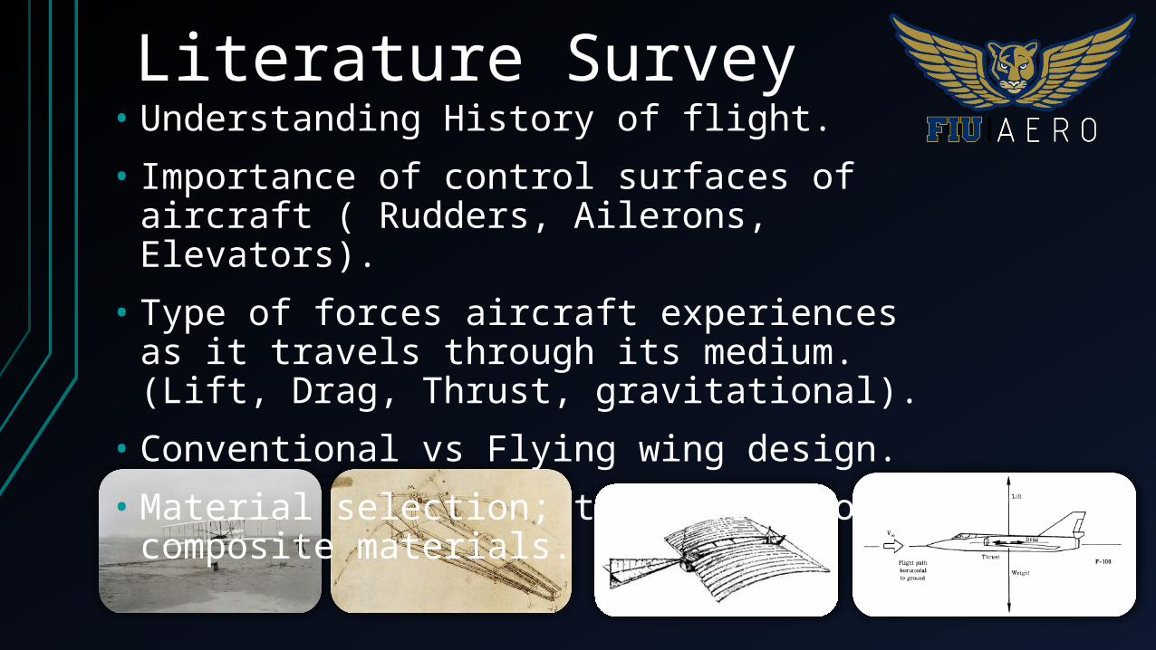
Literature Survey• Understanding History of flight.• Importance of control surfaces of aircraft ( Rudders,
Ailerons, Elevators). • Type of forces aircraft experiences as it travels through
its medium. (Lift, Drag, Thrust, gravitational).• Conventional vs Flying wing design.• Material selection; trade study of composite materials.

Literature Survey• Aircraft Design: A Conceptual Approach 5th Ed. by Daniel
Raymer• Simplified Aircraft Design for Homebuilders by Daniel Raymer• NACA References (National Advisory Committee for
Aeronautics)• Fluid Mechanics 7th Ed. by Frank M. White• Mechanical Engineering Design 9th Ed. by Richard G. Budynas
and J. Keith Nisbett• AIAA References• Military Design References

Global Learning• Competition allows for multi-cultural
participation • Engineering approach of different perspectives• Increase awareness of UAV’S in Global scale • Generate Multilingual User-Manual• SI/Imperical Units

Related Standards • FCC Radio Frequency Safety • Occupational Safety & Health Administration (OSHA)• Institute of Electrical and Electronic Engineers (IEEE)• Federal Aviation Administration (FAA)• American Society of the International Association for Testing
and Materials (ASTM)• International Organization for Standardization (ISO)• The American Society of Mechanical Engineers (ASME)
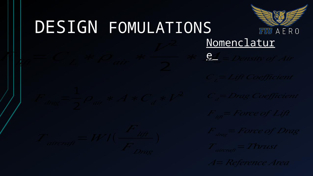
DESIGN FOMULATIONS
𝐹 𝑙𝑖𝑓𝑡=𝐶𝐿∗ 𝜌𝑎𝑖𝑟∗𝑉 2
2∗ 𝐴
𝐹 𝑑𝑟𝑎𝑔=12 𝜌𝑎𝑖𝑟∗𝐴∗𝐶𝑑∗𝑉 2
𝑇 𝑎𝑖𝑟𝑐𝑟𝑎𝑓𝑡=𝑊 / (𝐹 𝑙𝑖𝑓𝑡
𝐹 𝐷𝑟𝑎𝑔)
Nomenclature
𝜌𝑎𝑖𝑟=𝐷𝑒𝑛𝑠𝑖𝑡𝑦 𝑜𝑓 𝐴𝑖𝑟
𝐶𝐿=𝐿𝑖𝑓𝑡 𝐶𝑜𝑒𝑓𝑓𝑖𝑐𝑖𝑒𝑛𝑡
𝐶𝑑=𝐷𝑟𝑎𝑔𝐶𝑜𝑒𝑓𝑓𝑖𝑐𝑖𝑒𝑛𝑡
𝐹 𝑙𝑖𝑓𝑡=𝐹𝑜𝑟𝑐𝑒𝑜𝑓 𝐿𝑖𝑓𝑡
𝐹 𝑑𝑟𝑎𝑔=𝐹𝑜𝑟𝑐𝑒𝑜𝑓 𝐷𝑟𝑎𝑔𝑇 𝑎𝑖𝑟𝑐𝑟𝑎𝑓𝑡= h𝑇 𝑟𝑢𝑠𝑡𝐴=𝑅𝑒𝑓𝑒𝑟𝑒𝑛𝑐𝑒 𝐴𝑟𝑒𝑎
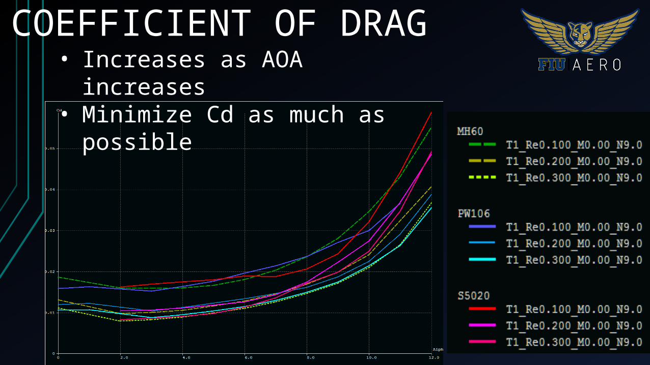
COEFFICIENT OF DRAG• Increases as AOA increases• Minimize Cd as much as possible

COEFFICIENT OF LIFT• Increases as AOA increases• Maximize Cl as much as possible

CENTER OF MOMENT• Increases as AOA increases• Close to zero provides best stability

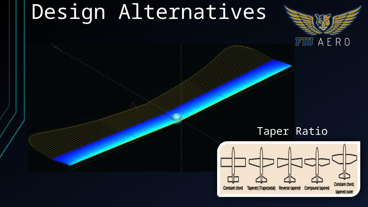
Design Alternatives
Aspect Ratio
Dihedral AngleAirfoils for Different Flight Condition
Design Alternatives
Taper Ratio

Design Alternatives
Sweep Angle

DESIGN ALTERNATIVE APros
Lowest wing loading Easiest packaging Lowest drag
Cons Least stable Lowest lift generated
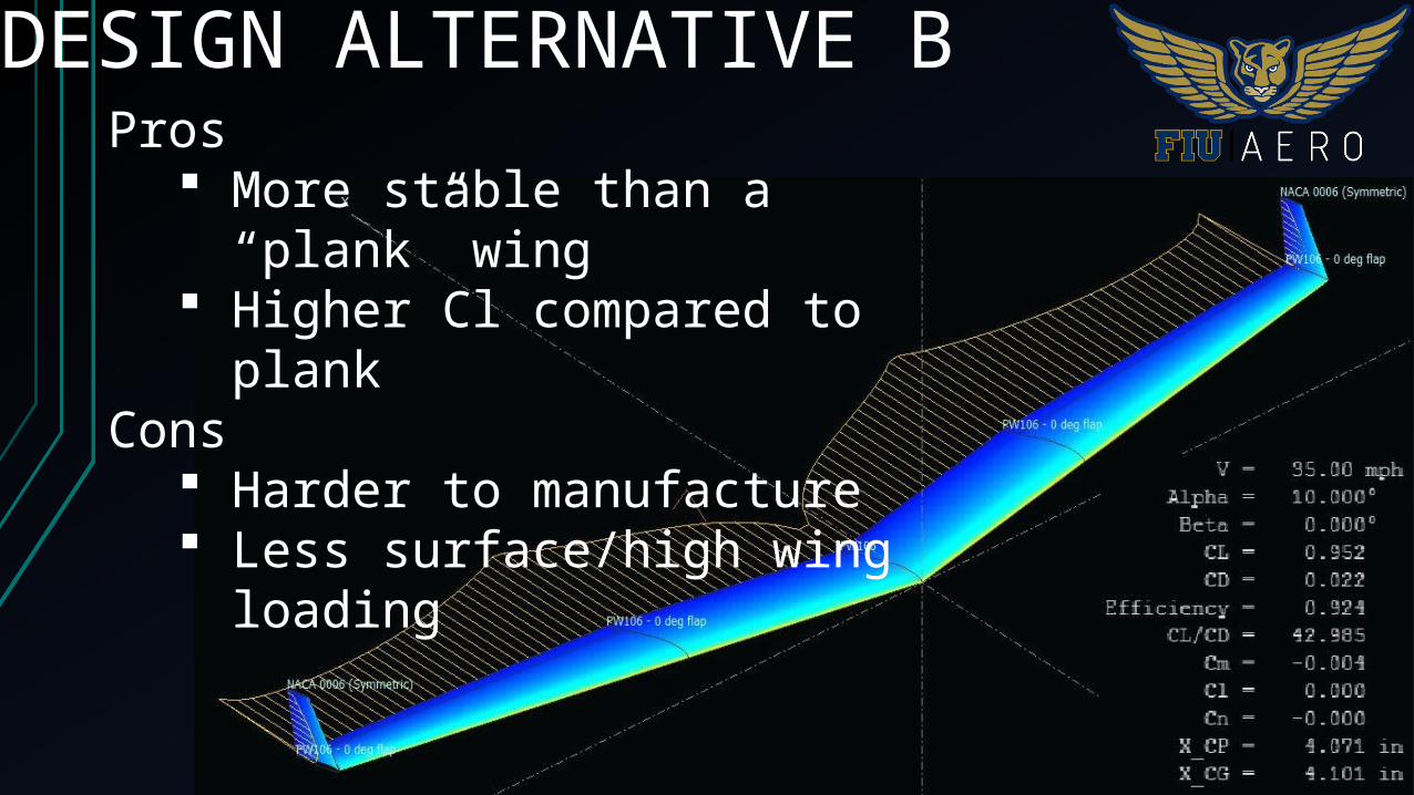
DESIGN ALTERNATIVE BPros
More stable than a “plank” wing Higher Cl compared to plank
Cons Harder to manufacture Less surface/high wing loading

DESIGN ALTERNATIVE CPros
Highest lift generated Most stable
Cons Highest drag Highest wing loading Hardest to manufacture
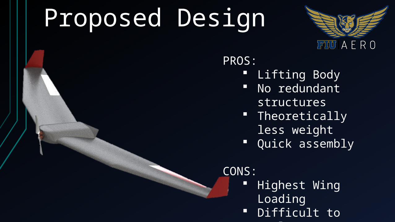
Proposed DesignPROS:
Lifting Body No redundant structures Theoretically less weight Quick assembly
CONS: Highest Wing Loading Difficult to analyze Difficult to manufacture Difficult to control
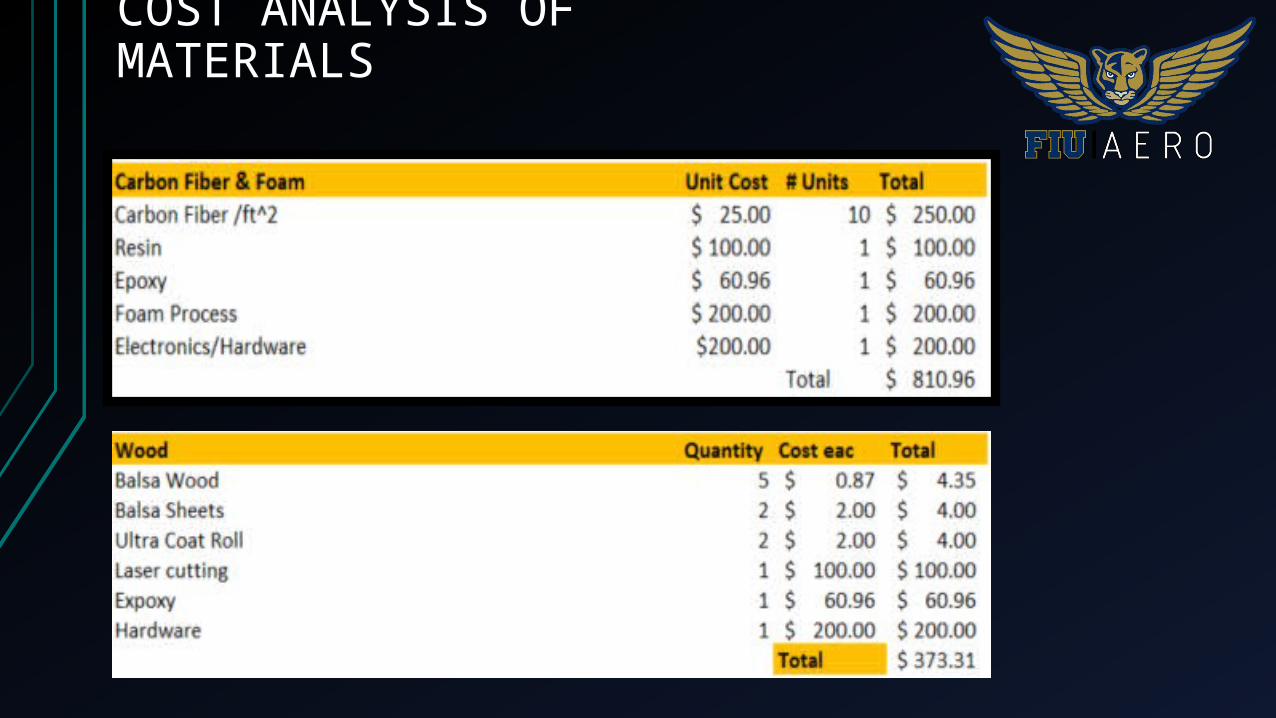
COST ANALYSIS OF MATERIALS
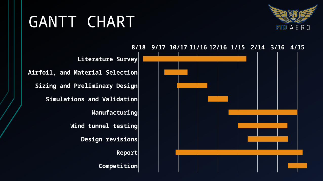
Literature Survey
Airfoil, and Material Selection
Sizing and Preliminary Design
Simulations and Validation
Manufacturing
Wind tunnel testing
Design revisions
Report
Competition
8/18 9/17 10/17 11/16 12/16 1/15 2/14 3/16 4/15
GANTT CHART

THANK YOU
GRACIAS
MERCI
谢谢