ta document tb2002001 technical bulletin 1394b clarifications and errata 1 · 2014-10-30 ·...
TRANSCRIPT
Copyright © 1996-2004 by the 1394 Trade Association.1111 South Main Street, Suite 100, Grapevine, TX 76051, USAhttp://www.1394TA.orgAll rights reserved.
Permission is granted to members of the 1394 Trade Association to reproduce this document for their own use or the use of other 1394 Trade Associationmembers only, provided this notice is included. All other rights reserved. Duplication for sale, or for commercial or for-profit use is strictly prohibited without theprior written consent of the 1394 Trade Association.
TA Document TB2002001
Technical Bulletin 1394b Clarifications andErrata 1.0
July 11, 2003
Sponsored by:Silicon Working Group of the 1394 Trade Association
Accepted for Release by:1394 Trade Association Board of Directors.
Abstract:This document notes errors and ambiguities that have been identified in IEEE Std 1394b-2002 andrecommends corrections and clarifications. It is a living document and will be updated as required.
Keywords:1394b, 1394a interoperability.
Technical Bulletin 1394b Clarifications and Errata 1.0 TA Document TB2002001, July 11, 2003
Page 2 Copyright © 2004, 1394 Trade Association. All rights reserved.
1394 Trade Association Specifications are developed within Working Groups of the 1394 Trade Association, anon-profit industry association devoted to the promotion of and growth of the market for IEEE 1394-compliantproducts. Participants in working groups serve voluntarily and without compensation from the Trade Association.Most participants represent member organizations of the 1394 Trade Association. The specifications developedwithin the working groups represent a consensus of the expertise represented by the participants.
Use of a 1394 Trade Association Specification is wholly voluntary. The existence of a 1394 Trade AssociationSpecification is not meant to imply that there are not other ways to produce, test, measure, purchase, market orprovide other goods and services related to the scope of the 1394 Trade Association Specification. Furthermore, theviewpoint expressed at the time a specification is accepted and issued is subject to change brought about throughdevelopments in the state of the art and comments received from users of the specification. Users are cautioned tocheck to determine that they have the latest revision of any 1394 Trade Association Specification.
Comments for revision of 1394 Trade Association Specifications are welcome from any interested party, regardlessof membership affiliation with the 1394 Trade Association. Suggestions for changes in documents should be in theform of a proposed change of text, together with appropriate supporting comments.
Interpretations: Occasionally, questions may arise about the meaning of specifications in relationship to specificapplications. When the need for interpretations is brought to the attention of the 1394 Trade Association, theAssociation will initiate action to prepare appropriate responses.
Comments on specifications and requests for interpretations should be addressed to:
Editor, 1394 Trade Association1111 South Main Street, Suite 100Grapevine, TX 76051, USA
1394 Trade Association Specifications are adopted by the 1394 Trade Association without regardto patents which may exist on articles, materials or processes or to other proprietary intellectualproperty which may exist within a specification. Adoption of a specification by the 1394 TradeAssociation does not assume any liability to any patent owner or any obligation whatsoever tothose parties who rely on the specification documents. Readers of this document are advised tomake an independent determination regarding the existence of intellectual property rights, whichmay be infringed by conformance to this specification.
TA Document TB2002001, July 11, 2003 Technical Bulletin 1394b Clarifications and Errata 1.0
Copyright © 2004, 1394 Trade Association. All rights reserved. Page 3
Table of contents
1. Overview.............................................................................................................................................................71.1 Purpose ......................................................................................................................................................71.2 Scope .........................................................................................................................................................7
2. References...........................................................................................................................................................8
3. Definitions...........................................................................................................................................................93.1 Conformance levels ..................................................................................................................................93.2 Glossary of terms ......................................................................................................................................93.3 Acronyms and abbreviations ....................................................................................................................9
4. 1394b errata ......................................................................................................................................................104.1 Legacy Port does not calculate isoch_pending and async_pending.....................................104.2 Exit from P6 does not always clear in_standby ..............................................................................104.3 Possible race condition with pending_port, async_pending, isoch_pending ................104.4 Race condition between PMD_UNSELECT_PORT and PMD_TONE_ON ............................................114.5 Need Reset on bad restore packet...........................................................................................................124.6 Balanced Transmitter test circuit............................................................................................................124.7 Beta_mode not cleared on force_disconnect .........................................................................................124.8 Reconnection while disabled ..................................................................................................................134.9 Treatment of suspend fault .....................................................................................................................134.10 Connection status toning and bias phasing ..........................................................................................144.11 Port power reset duration......................................................................................................................154.12 Signal detect latching............................................................................................................................154.13 Legacy camcorder interoperability.......................................................................................................154.14 Inconsistent behavior on disable-notify ...............................................................................................184.15 Maintaining connectivity while disabled .............................................................................................194.16 Exit from disabled on a Beta_mode port..............................................................................................204.17 Changing from toning to trying bias in Eager Beta.............................................................................204.18 Moving asynchronously to a resume-type state (P1, P10 or P11) ......................................................204.19 Beta Port Resynchronization ................................................................................................................224.20 Beta Port Control reception ..................................................................................................................224.21 S100/S200 Legacy packets w/ legacy phase........................................................................................224.22 UTP-5 deployment recommendation ...................................................................................................234.23 Self-ID brdg field ..................................................................................................................................234.24 Enable_standby on LPS active .............................................................................................................234.25 Transition to disabled............................................................................................................................244.26 Clearing do_standby in suspend_initiator............................................................................................254.27 Allow cycle start requests during Initialization Completion Sequence ..............................................254.28 Global connect_timer............................................................................................................................254.29 Resume_actions and reset_start_actions use different conditions ......................................................264.30 Junior PHY's stuck in receive_actions following end of iso gap ........................................................274.31 Clarify short circuit Boolean evaluation ..............................................................................................274.32 Transition from untested_actions to loop_disabled, disconnected .....................................................284.33 Action on speed code error on B-Bus ..................................................................................................284.34 DS_stuck and dribble bits.....................................................................................................................294.35 Beta_mode resume_fault ......................................................................................................................304.36 S800 Electrical Specification................................................................................................................314.37 Connector Specification clarifications .................................................................................................394.38 Shield and connector sequencing .........................................................................................................41

Technical Bulletin 1394b Clarifications and Errata 1.0 TA Document TB2002001, July 11, 2003
Page 4 Copyright © 2004, 1394 Trade Association. All rights reserved.
List of tables
Table 1 – Content change for version 1.21............................................................................................................5Table 2 – Content change for version 1.22............................................................................................................5Table 3 – Content change for version 1.3..............................................................................................................5Table 4 – Content change for version 1.4..............................................................................................................6Table 5 – Content change for version 1.5..............................................................................................................6Table 6 – Content change for version 1.6..............................................................................................................6
TA Document TB2002001, July 11, 2003 Technical Bulletin 1394b Clarifications and Errata 1.0
Copyright © 2004, 1394 Trade Association. All rights reserved. Page 5
Change history
The following table shows the change history for this specification.
Version 1.0 (May 3rd, 2002)
Original version.
Version 1.1 (May 14t h 2002)
Initial published version
Version 1.21 (July 5t h 2002)
Table 1 – Content change for version 1.21
Category Description
Editorial
Technical Added 4.6 thru 4.15
Version 1.22 (July 15 t h 2002)
Table 2 – Content change for version 1.22
Category Description
Editorial Updated to new TA template
Technical
Version 1.3 (October 14t h 2002)
Table 3 – Content change for version 1.3
Category Description
Editorial Changed reflector from 1394-Architecture to 1394-Silicon
Technical Added 4.16 – 4.23; updated 4.11 and 4.14, and added reference to PHY register port statusfields in 4.11;

Technical Bulletin 1394b Clarifications and Errata 1.0 TA Document TB2002001, July 11, 2003
Page 6 Copyright © 2004, 1394 Trade Association. All rights reserved.
Version 1.4 (January 16t h 2003)
Table 4 – Content change for version 1.4
Category Description
Editorial Changed title to “Clarifications and Errata”
Technical Updated 4.6. Added 4.24 - 4.32
Version 1.5 (March 5t h 2003)
Table 5 – Content change for version 1.5
Category Description
Editorial Added cross-reference from 4.7 to 4.39, deleted empty list of figures, updated references tobe consistent with the published version of 1394b
Technical Updated 4.32. Added 4.33 – 4.41
Version 1.6 (July 11t h 2003)
Table 6 – Content change for version 1.6
Category Description
Editorial Changes according to Ballot Review Committee comment resolution
Technical (none)
TA Document TB2002001, July 11, 2003 Technical Bulletin 1394b Clarifications and Errata 1.0
Copyright © 2004, 1394 Trade Association. All rights reserved. Page 7
1. Overview
1.1 Purpose
The purpose of this Technical Buletin is assist interoperability of 1394b and Legacy implementations by identifyingerrors and issues, and by recommending corrections.
1.2 Scope
This document identifies errors and ambiguities that have been identified in IEEE Std 1394b-2002 and recommendscorrections and clarifications. This Technical Bulletin is a living document with an anticipated life span of 6 - 18months from publication of IEEE Std 1394b-2002 and will be updated from time to time as appropriate. During thistime during the Architecture working group hopes that individuals will come forward with any suspected errata inIEEE Std 1394b-2002 that they believe should be discussed. Discussion of such errata should take place on BOTHthe IEEE P1394b reflector ([email protected]) and the 1394 TA Architecture working group reflector ([email protected]).
Technical Bulletin 1394b Clarifications and Errata 1.0 TA Document TB2002001, July 11, 2003
Page 8 Copyright © 2004, 1394 Trade Association. All rights reserved.
2. References
The following standards contain provisions, which through reference in this document, constitute provisions of thisstandard. All the standards listed are normative references. Informative references are given in Annex A. At the timeof publication, the editions indicated were valid. All standards are subject to revision, and parties to agreementsbased on this standard are encouraged to investigate the possibility of applying the most recent editions of thestandards indicated below.
[R1] IEEE Std 1394b-2002, Standard for a High Performance Serial Bus (High Speed Supplement)
[R2] IEEE Std 1394-1995, Standard for a High Performance Serial Bus.
TA Document TB2002001, July 11, 2003 Technical Bulletin 1394b Clarifications and Errata 1.0
Copyright © 2004, 1394 Trade Association. All rights reserved. Page 9
3. Definitions
3.1 Conformance levels
3.1.1 expected: A key word used to describe the behavior of the hardware or software in the design models assumedby this Specification. Other hardware and software design models may also be implemented.
3.1.2 may: A key word that indicates flexibility of choice with no implied preference.
3.1.3 shall: A key word indicating a mandatory requirement. Designers are required to implement all suchmandatory requirements.
3.1.4 should: A key word indicating flexibility of choice with a strongly preferred alternative. Equivalent to thephrase is recommended.
3.1.5 reserved fields: A set of bits within a data structure that are defined in this specification as reserved, and arenot otherwise used. Implementations of this specification shall zero these fields. Future revisions of thisspecification, however, may define their usage.
3.1.6 reserved values: A set of values for a field that are defined in this specification as reserved, and are nototherwise used. Implementations of this specification shall not generate these values for the field. Future revisions ofthis specification, however, may define their usage.
NOTE — The IEEE is investigating whether the “may, shall, should” and possibly “expected” terms will be formally defined byIEEE. If and when this occurs, draft editors should obtain their conformance definitions from the latest IEEE style document.
3.2 Glossary of terms
3.2.1 byte: Eight bits of data, used as a synonym for octet.
3.2.2 CSR Architecture: A convenient abbreviation of the following reference (see clause 2): ISO/IEC 13213 :1994 [ANSI/IEEE Std 1212, 1994 Edition], Information Technology—Microprocessor systems— Control andStatus Register (CSR) Architecture for Microcomputer Buses.
3.2.3 quadlet: Four bytes of data.
3.3 Acronyms and abbreviations
IEEE The Institute of Electrical and Electronics Engineers, Inc.
Technical Bulletin 1394b Clarifications and Errata 1.0 TA Document TB2002001, July 11, 2003
Page 10 Copyright © 2004, 1394 Trade Association. All rights reserved.
4. 1394b errata
4.1 Legacy Port does not calculate isoch_pending and async_pending
DescriptionIn process_req.cThe error crept in when the Beta_mode[i] qualification was added to the if statement beginning with
//combine best async and isoch request from other ports and own request if (active[i] && Beta_mode[i]){
in the file process_req.c. This addition was logged against SCAT number 454.
RecommendationThe necessary tests on Beta_mode[i] are included in the code within the loop. Amend two quoted lines inClause 19.4.2 Figure 19-18 to read
//combine best async and isoch request from other ports and own request if (active[i]){
4.2 Exi t from P6 does not always clear in_standby
DescriptionIn port.cIf start_port() fails when called from restore_actions, then in_standby is not cleared on P6:P0
RecommendationAmend Clause 19.2.2, Figure 19-7 to clear in_standby:-
if (!start_port()) { // Resume attempt failed if failed to synchronize restore = FALSE; force_disconnect = TRUE; while (connected) ; if (proxy) isbr = TRUE; // bus reset on disconnection, arbitrated for uncle, else ibr = TRUE; // immediate for nephew proxy = FALSE; // uncle no longer proxies for nephew in_standby = FALSE; return; // restore attempt failed
}
4.3 Possible race condition with pending_port , async_pending , isoch_pending
DescriptionIn process_requests.c and main arb state machineIn process_req.c, async_pending and isoch_pending are updated before pending_port. However, themain arb state machine process (running concurrently) can sample these signals asynchronously. So it istheoretically possible to see isoch_pending set, say, and then sample a not-yet-updated value forpending_port. In summary, updates to async/isoch_pending and pending_port are not atomic.
RecommendationSplit pending_port into async_pending_port and isoch_pending_port. Then, for example,isoch_pending_port is updated before isoch_pending, thereby guaranteeing that onceisoch_pending is sampled true, the value of isoch_pending_port is safe to sample. Amend Clause 19.1Figure 19-5 (shared.h) to delete the definition of pending_port and to introduce the definitions:-

TA Document TB2002001, July 11, 2003 Technical Bulletin 1394b Clarifications and Errata 1.0
Copyright © 2004, 1394 Trade Association. All rights reserved. Page 11
int async_pending_port; // port for pending request (NPORT if from the local (Beta) link)int isoch_pending_port; // port for pending request (NPORT if from the local (Beta) link)
Amend Clause 19.4.1, Figure 19-16
} else if (isoch_pending && !proxy_root) { // pipelined Beta isoch request to be forwarded converted_request = TRUE; // isoch_pending and async_pending used only at senior_border own_request = (isoch_pending_port == NPORT); // if at proxy_root, use OK_to_grant mechanism // (see idle_actions). requesting_port = isoch_pending_port; grant_to_give = GRANT_ISOCH;
and
} else if (async_pending && async_arb_OK && !proxy_root) { converted_request = TRUE; own_request = (async_pending_port == NPORT); requesting_port = async_pending_port; grant_to_give = GRANT;
Amend Clause 19.4.2 Figure 19-18
arbreqT[i] = best_req; //different for each port if (senior_border && (i == senior_port)) { // need to convert to Legacy and pass any // request up to DS parent async_pending_port = bap; // meaningless unless async_pending is TRUE isoch_pending_port = bip; // meaningless unless isoch_pending is TRUE isoch_pending = ((iso_cycle && ((best_req.isoch & ipm) >= (ISOCH_IN_PHASE & ipm))) || (!iso_cycle && ((best_req.isoch & ipm) == (ISOCH_CURRENT & ipm)))); async_pending = (!iso_cycle && ((best_req.async & apm) >= (CURRENT & apm)));
}
4.4 Race condition between PMD_UNSELECT_PORT and PMD_TONE_ON
DescriptionIn port.cThe failure mode was observed as follows:- When a cable was disconnected, the P2:P3 transition tested true.connection_status sees the arrival in P3 and the loss of rx_ok and sets toning TRUE. At the same time, theP3 actions in suspend_initiator_actions make a call to activate_connect_detect. The intent isfor activate_connect_detect to PMD_UNSELECT_PORT first followed by the toner doing PMD_TONE_ONrequests because toning is TRUE. However, the parallel processes race. Only one process should be controlling aport at any one time.
RecommendationAmend the definition of PMD_TONE_ON in Clause 16.2.5.1 to:-
PMD_TONE_ON. Instructs the PMD to generate a tone (see clause 9.6.1). Infers PMD_UNSELECT_PORT.
4.5 Need Reset on bad restore packet
DescriptionIn rx_PHY_packet() routine there is a line of code that reads "kill bad packets" (Clause 19.2.1, Figure 19.6).
The consequence of the actions in con_mgmnt_granted() in this case is to allow the restoring leaf node tocomplete the restore process and load incorrect values (all 0s) for all the parameters that are supposed to come fromits uncle (including physical ID, gapcount, B_bus etc) and happily become an active node on the bus.
Recommendation
Technical Bulletin 1394b Clarifications and Errata 1.0 TA Document TB2002001, July 11, 2003
Page 12 Copyright © 2004, 1394 Trade Association. All rights reserved.
The nephew should initiate a short bus reset under this condition, given that the PHY has the attention of the wholebus at this time.
The PHY configuration packet is by definition non-zero, so in con_mgmnt_granted() (called from TX actions)read the config packet (as now), then test for a zero packet, and if so set isbr_OK to TRUE, and "break" to exitfrom the loop and con_mgmnt_granted, and take TX_>R0.
} else { // nephew actions // restored leaf node - receive updated information from peer port config_pkt = rx_PHY_packet(i); // and set the port active if (config_pkt.dataQuadlet == 0) { // bad restore packet isbr_OK = TRUE; immediate_restore_request = FALSE; break; }
4.6 Balanced Transmitter test c ircuit
DescriptionFigure 9-3 shows a common mode connection to ground. This erroneously implies a low impedance common modetest load.
RecommendationThe common mode connection to ground shown in Figure 9-3 should not be incorporated in the test circuit if thetransmit network is DC coupled (see 4.36).
4.7 Beta_mode not cleared on force_disconnect
DescriptionThe background processing in connection_status() does not clear the Beta_mode flag when adisconnection is forced. The result is that the local port will behave as if a Beta mode connection still exists, whereasthe remote port will start up with speed negotiation etc.
RecommendationAdd one line of C code to set Beta_mode to FALSE:-
if (force_disconnect) { // caused by failure to startup while in P10 or if a Legacy loop isdetected activate_connect_detect(0); connected = FALSE; Beta_mode = FALSE; wait_time(2 * DISCONNECTED_TONE_INTERVAL); // ensure the far end sees a "disconnection" force_disconnect = FALSE; }
4.8 Reconnect ion while disabled
DescriptionIf a port is disabled (though not hard disabled), and then disconnected, and then reconnected (possibly to a differentnode), the background processing in connection_status renegotiates the connection type and, if Beta mode, theoperating speed. If int_enable is not set, then the connected variable is not updated, to match the 1394abehavior. If int_enable is set, then the connected variable is updated and the background processing waitsuntil the port state machine enters “untested”. This is not appropriate in this case (it is appropriate in the case of aport in P0).
RecommendationClause 19.2.2 Figure 19.7, p288. Add a qualification of disabled in the code which waits for a port transition.
TA Document TB2002001, July 11, 2003 Technical Bulletin 1394b Clarifications and Errata 1.0
Copyright © 2004, 1394 Trade Association. All rights reserved. Page 13
if (set_Beta()) { // try Beta mode if (disabled && !int_enable) return; // (compatible with Legacy) connected = TRUE; while (!(untested_state || disabled)) // wait till in untested_state ; return; }
4.9 Treatment of suspend fault
DescriptionThe current code allows for the possibility that a Beta connection may end up in suspend with a suspend_fault(possibly because the other end didn't suspend in time?). In P5, toning will be turned on, causing receive_OK tobe false. P5:P5 then executes and clears suspend_fault. Since the far end hasn't yet suspended,connection_status will see continuous signaling and turn off toning, allowing receive_ok to be set true. With!suspend_fault && receive_ok, P5:P1 is enabled and the port will start to resume. The intent was to havethe same behavior as 1394a, i.e. to stay in P5 with a fault.
RecommendationClause 19.2.2 Figure 19.7, p283. Change the receive_ok code so that it will continue to report TRUE if there isan incoming continuous signal, even though the local node is toning. Change the description of Receive_OK in thePort status page by deleting the parenthetical exception. Add a filter to avoid reporting TRUE on incoming tones(which is the intent of the current code).
void receive_ok_monitor() { // continuously running timer receive_ok_timer; if (power_reset) { receive_ok = rx_ok = FALSE; receive_ok_timer = 0; while (power_reset) ; } // Evaluate receive_ok if (Beta_mode) { if (!(PMD_STATUS_request() & PMD_SIGNAL_DETECT)) { receive_ok = FALSE; receive_ok_timer = 0; } else if (receive_ok_timer == TONE_DURATION * 5 / 4) // Signal detect currently true, is it continuous? receive_ok = TRUE; } else if (Beta_mode_only_port) { receive_ok = FALSE; receive_ok_timer = 0; } else { receive_ok = bias; receive_ok_timer = 0; } // Assign rx_ok rx_ok = Beta_mode ? bport_sync_ok: bias;}
Clause 19.2.2 Figure 19.7, p289. Adjust the connection_status code not to turn off toning on a suspend fault.
if (signal_detect_OK()) { // still true - continuous tone if (!disabled) { // in P5:suspended state if (!suspend_fault) toning = FALSE; // turn off the autonomous toner } return; } break; // connected, but no continuous tone
Clause 19.2.2 Figure 19.7, p291. Change the tests and handshake on rx_ok in P3 and P7 to use receive_ok.
Technical Bulletin 1394b Clarifications and Errata 1.0 TA Document TB2002001, July 11, 2003
Page 14 Copyright © 2004, 1394 Trade Association. All rights reserved.
else { // Instructed to suspend signaled = FALSE; while ((connect_timer < RECEIVE_OK_HANDSHAKE) && receive_ok) ; // Wait for suspend target to deassert receive_ok suspend_fault = receive_ok; // Suspend handshake refused by target? activate_connect_detect(RECEIVE_OK_HANDSHAKE); // Also guarantees handshake timing }
void standby_initiator_actions() { in_standby = TRUE; // for the purpose of port status accounting connect_timer = 0; // Used to debounce receive_ok or for receive_okhandshake signaled = FALSE; while ((connect_timer < RECEIVE_OK_HANDSHAKE) && receive_ok) ; // Wait for suspend target to deassert receive_ok standby_fault = receive_ok; // Standby handshake refused by target? activate_connect_detect(RECEIVE_OK_HANDSHAKE); // Also guarantees handshake timing}
Clause 19.2.2 Figure 19.7, p289. Change the test on rx_ok in connection_status when in P3, P4, P7 or P8 toreceive_ok
// turn on toning if going into a suspend-type state if (!receive_ok && ((port_state == P3) || (port_state == P4) || (port_state == P7) || (port_state == P8))) toning = TRUE; // turn on toning as soon as possible
4.10 Connection status toning and bias phasing
DescriptionNode B powers up just Node A was at the point of sending one last tone and then was going to try BIAS. Node Bcatches the last tone and starts the debounce period. At the conclusion of the period, set_Beta is calledunconditionally. Node B still sending Bias, so set_Beta fails and connection_unreliable is set. The twonodes subsequently will get into phase and will succeed in connecting, but the connection_unreliableindication is inappropriate. The connection also takes a longer time than needed.
RecommendationClause 19.2.2 Figure 19.7, p288. Add a test on bias in the debounce wait, and another test should set_Beta fail.
if (signal_detect_OK()) { // heard tone, now debounce tone_test_timer = 0; while ((tone_test_timer < CONNECT_TIMEOUT) && !bias) // interval to ignore bouncing ; if (bias) break; if (set_Beta()) { // try Beta mode if (disabled && !int_enable) return; // (compatible with Legacy) connected = TRUE; while (!(untested_state || disabled)) // wait till in untested_state ; return; } if (bias) break;
4.11 Por t power reset duration
Descriptionport_power_reset waits 2*DTI to keep the port state machine at bay during a power_reset. However,connection_status contains only a wait on power_reset, and no explicit 2*DTI. Consequently, it ispossible to start toning and establish connectivity long before the port state machine would be willing to leave P0,which is not the intent. If power_reset duration > 2*DTI, then the problem doesn't happen.
TA Document TB2002001, July 11, 2003 Technical Bulletin 1394b Clarifications and Errata 1.0
Copyright © 2004, 1394 Trade Association. All rights reserved. Page 15
RecommendationClause 19.2.2 Figure 19.7, p287. Move the delay into the power reset loop in connection_status (deleting itfrom port_power_reset). The effect is that the port state machine moves immediately to P0, but toning etc willbe delayed for at least 2*DTI.
if (power_reset) { Beta_mode = bport_on = connected = connection_unreliable = crossover = dsport_on = listening_for_speed = send_speed = toning = tried_bias = FALSE; PMD_CONTROL_request(PMD_UNSELECT_PORT, 0); PMD_CONTROL_request(PMD_NO_CROSSOVER, 0); wait_time(2*DISCONNECTED_TONE_INTERVAL); // ensure that there is more than one tone // interval since a signal was transmitted // so that the peer port moves into disconnected while (power_reset) ; return;
4.12 Signal detect latching
DescriptionThe C code signal_detect_OK() function and signal detect latch does not take account of the +-100ppmfrequency differences which are allowed between the clock at the transmitter and that at the receiver. In addition,low power clocks may, in practice, be more than +-100ppm.
RecommendationClause 19.2.2, Figure 19-7, add C code comment above the signal_detect_OK() function:-// The C code signal_detect_OK() function and signal detect latch does not take account of// the +-100ppm frequency differences which are allowed between the clock at the transmitter// and that at the receiver. In addition, low power clocks may, in practice, be more than// +-100ppm.. Implementers are cautioned to ensure that implementations take account of// these timing considerations, plus margin (for example, by oversampling).
4.13 Legacy camcorder interoperabil i ty
Description1394b has shown up a problem in some 1394a devices. This is not a 1394b error, but changes are recommended in1394b implementations to improve interoperability with Legacy devices which exhibit this problem.
The failure has been observed in which a legacy CE device (in particular, some types of camcorders) would initiatea bus-reset when it received a cycle-start packet followed by a concatenated isochronous packet. The device wouldinitiate the bus-reset before it had started to receive the data payload of the concatenated isochronous packet; thisindicates that it was the act of concatenation that caused the bus-reset, as opposed to, e.g., insufficient time intervalbetween end of cycle-start packet data and start of isochronous packet data.
This failure did not occur when the offending device was connected to 1394a or 1394-1995 PHY/link nodes. This,apparently, is because these 1394a or 1394-1995 PHY/link devices do not concatenate isochronous packets onto thecycle-start packet, although it is certainly allowed for a cyclemaster to do this in 1394-1995 and 1394a.
It is unknown why the offending device behaves in this way.
RecommendationThe work-around solution is to prevent concatenation onto the cycle start packet. Note that every 1394b PHY has toimplement this, as it is possible in 1394b in some circumstances for non-root PHYs to concatenate onto a cycle startpacket.
This is achieved by using an isoch_concat_ok flag, which is cleared whenever the PHY is in a hybrid bus andin the async period (iso_cycle is false), and is set true when in the isoch period and a packet is terminated with
Technical Bulletin 1394b Clarifications and Errata 1.0 TA Document TB2002001, July 11, 2003
Page 16 Copyright © 2004, 1394 Trade Association. All rights reserved.
data-end. (The flag is held true when in a B_bus.) The flag then remains set true until iso_cycle is cleared. Ifthe isoch_concat_ok is false and iso_cycle is true, a transmitted packet will be forced to be terminated bydata-end. Likewise, a received packet terminated by data-end will not have any packet fly-by concatenated onto it.However, a received packet terminated by isoch-grant will allow fly-by concatenation in the normal manner (as it isnecessary to reply somehow to a grant, especially a grant from the senior).
Thus, in a hybrid bus consisting of Beta PHYs, all of which implemented the isoch_concat_ok flag, the cyclestart packet would be forced to be terminated by data-end, and no other Beta node could concatenate onto it. Aftercompletion of the cycle start packet, terminated by data-end, the isoch_concat_ok flag would be set true andisochronous concatenation to subsequent isochronous packets could proceed in the normal manner.
The recommended changes to the C code are summarized as follows:-
Clause 19.4.1 Figure 19.17, p328 In beta_arb_functions.c, test_requests(..)
request_to_service = TRUE; // Until proven otherwise if (own_req.async == BORDER) // only when senior border request_to_service = FALSE; else if ((*received_grant == GRANT_ISOCH) && in_phase_isoch_request) *best_port = bip; else if ((*received_grant == GRANT) && in_phase_async_request) *best_port = bap; else if ((*received_grant == DATA_END) && (best_req.isoch == ISOCH_CURRENT) && isoch_concat_ok) { // don't encourage another node to concatenate // for Legacy camcorder problem *best_port = bip; *received_grant = GRANT_ISOCH; // upgrade to an explicit isoch grant } else request_to_service = FALSE;
Clause 19.4.1 Figure 19.17, p332 In beta_arb_function, gap_repeat_actions(..)
if (iso_cycle) { // either token ends the isoch interval iso_cycle = FALSE; odd_isoch_phase = !odd_isoch_phase; // advance phase at end of isoch interval isoch_concat_ok = B_bus; // for Legacy camcorder interoperability }
Clause 19.4.1 Figure 19.15, p323 In decode_PHY_packet
if ((self_ID_pkt.ext == 0) && (!Beta_mode[receive_port] || !received_speed_signal)) { // originated from node with Legacy link or DS node B_bus = FALSE; isoch_concat_ok = FALSE; // For Legacy camcorder interoperability
Clause 19.4.1 Figure 19.16, p325 In ds_arb_functions.c, fly_by_permitted()
boolean fly_by_permitted() { // TRUE if fly-by acceleration OK if (!(link_CS_indications || root)) // Legacy links at root don't provide indications return(FALSE); else if (receive_port == senior_port) return(FALSE); else if (req_speed == S100 && cur_speed != S100) return(FALSE); else if (iso_cycle && !isoch_concat_ok) // Legacy camcorder problem return (FALSE); else if (breq == ISOCH_REQ) return(TRUE);
Clause 19.2.1 Figure 19.6, p277 In node.c for a restoring node
TA Document TB2002001, July 11, 2003 Technical Bulletin 1394b Clarifications and Errata 1.0
Copyright © 2004, 1394 Trade Association. All rights reserved. Page 17
config_pkt = rx_PHY_packet(i); // and set the port active start_tx_packet(S100, BETA, FALSE); // send null packet physical_ID = config_pkt.root_ID; gap_count_reset_disable = config_pkt.T == 1; gap_count = config_pkt.gap_count; max_Legacy_path_speed = config_pkt.notify_Legacy_speed; B_node_root = config_pkt.notify_B_node_root == 1; B_bus = config_pkt.notify_B_bus == 1; isoch_concat_ok = B_bus; // for Legacy camcorder problem odd_async_phase = config_pkt.notify_odd_async_phase == 1;
Clause 19.4.3 Figure 19.19, p341 In reset.c
B_bus = TRUE; // initially an isolated node! isoch_concat_ok = TRUE; // for Legacy camcorder problem
Clause 19.4.3 Figure 19.21, p347 In selfid_transmit_actions
B_node_root = FALSE; B_bus = FALSE; isoch_concat_ok = FALSE; // For Legacy camcorder interoperability problem
Clause 19.1 Figure 19.5, p268 In shared.h
// shared between the main arb state machine and node.c
int gap_count;boolean gap_count_reset_disable; // If set, a bus reset will not force the gap_count to themaximumboolean isoch_concat_ok; // TRUE when isoc concatenation will not upset Legacycamcorders
Clause 19.5 Figure 19.24, p357 In transmit_actions
if (iso_cycle) // Implicit or explicit subaction end grant_type = isoch_concat_ok ? GRANT_ISOCH : DATA_END; // Force to DE for Legacycamcorder
Clause 19.4.1 Figure 19.13, p317 In transmit functions
if ((tx_arb == BUS_RESET) || (tx_arb == IDLE)) return; // Immediate exit to R0 or A0
if ((tx_arb == DATA_END) && iso_cycle) isoch_concat_ok = TRUE; // OK to concat now for Legacy camcorder
4.14 Inconsistent behavior on disable-notify
DescriptionThere is an inconsistency/problem with an active Beta port going into the Disabled state.
A Beta mode port that is in the Disabled state, and still marked as connected, will transition to the Untested statewhen the disabled flag is cleared (by a register write or by a remote-command packet). This implies that theconnected peer port should be in the Loop_disabled state, waiting for the peer to resume continuous signaling.
However, when a commanded disable-notify is executed, the initiator will transition to the Disabled state and thetarget will transition to the Suspended state. Now,if the disabled flag is cleared, the two ports will not be able toresume active status since one port would be attempting loop-test operations and the other would be attemptingresume operations.
Recommendation
Technical Bulletin 1394b Clarifications and Errata 1.0 TA Document TB2002001, July 11, 2003
Page 18 Copyright © 2004, 1394 Trade Association. All rights reserved.
When a Beta port receives a disable-notify (i.e., it is the target) that it simply force a disconnect (D/S mode portsbehave the same way as in 1394a and transition to the Suspended state). If the port remains connected (i.e., toning ismaintained), then the port will perform speed-negotiation and then transition to the Untested state. If the peer port isstill disabled, then the loop-test will fail and the port will transitionto the Loop_disabled state, as desired. Likewise,the Beta initiator of the disable-notify should also force a disconnect upon the transition from Active to Disabled(this is a redundancy since the loss of connection tones from the peer would cause the port to lose connection status,but it seems a safe thing to do).
With this proposal, when an active Beta port is commanded to disable (via a remote-command packet), it will send adisable-notify to its peer and then transition to the Disabled state and force a disconnect. The peer, upon receivingthe disable-notify, will force a disconnect and transition to the Disconnected state. The disabled port will generateconnection tones, and a connection will be established with the peer. But because the port is disabled, the peer portwill fail loop-test and will transition to the Loop_disabled state, as desired. When the disabled bit is cleared, the portand its peer will both transition to the Untested state.
In the c-code, implement a force-disconnect in the disable-notify scenario by use of the sync_fail flag (similar tothe way it's used in the loss-of-sync scenario). In P4, a Beta port would set the sync_fail flag if P4 was entereddue to a received disable-notify signal, causing the port to quickly transition thru P4 and P5 back to P0, and clearingthe port's connected flag (which also causes the Beta_mode flag to be cleared in the connection_status function).Likewise, upon entry into P6 in Beta mode, the port would set the sync_fail flag. The details of thisrecommendation, when considered in combination with the recommendation for 4.15 below, allows a combinedsolution to the two issues.
Clause 19.2.2 Figure 19.7 p291 In port.c, suspend_target_actions()
if (portRarb == DISABLE_NOTIFY) { // Is our peer PHY going away? sync_fail = TRUE; // To force transition from P5 to P0 immediate_phy_request = TRUE; // Topology change! Reset on other (active) ports
Clause 19.2.2 Figure 19.7 p290 In disabled_actions()
if (disable_request) disable_request = signaled = connected = FALSE;
4.15 Maintaining connectivity while disabled
DescriptionWhen a port is disabled (but not hard_disabled), the connected flag is false and the Beta_mode flag is false, thenconnection_status() attempts to establish a new connection. This is needed to ensure that a peer port canmaintain connection status. When a Beta mode connection is established and the int_enable flag is not set, thenthe Beta_mode flag is set TRUE, but the connected flag is NOT set TRUE, to maintain compatibility with 1394a.However, the "know_still_Beta_mode" section of code in connection_status() kills the Beta_mode flag ifconnected is FALSE. The port will then attempt to go back to toning and negotiating speed, but the peer port willsimply maintain toning.
RecommendationIn combination with the recommendation for 4.14 above, the sync_fail flag is used directly in connection_status.The flag is set in disabled_actions, suspend initiator_actions, or suspend_target actions. The connection_statusroutine will force a disconnect when in P5:suspended or P6: disabled states and sync_fail is set. Thedisabled_actions and suspended_actions wait for sync_fail to be cleared before proceeding. The result is that theconnected and Beta_mode flags are set and cleared only in connection_status, eliminating the possibilty of raceconditions concerning these flags between the backgrond processing and the foreground port state machine.
Clause 19.2.2 Figure 19.7 p291 In port.c, suspend_target_actions()
TA Document TB2002001, July 11, 2003 Technical Bulletin 1394b Clarifications and Errata 1.0
Copyright © 2004, 1394 Trade Association. All rights reserved. Page 19
if (portRarb == DISABLE_NOTIFY) { // Is our peer PHY going away? immediate_phy_request = TRUE; // Topology change! Reset on other (active) ports isbr = isbr_OK = TRUE; if (Beta_mode) sync_fail = TRUE; // force disconnection if other end going intodisabled
Clause 19.2.2 Figure 19.7 p291 In suspended_actions()
void suspended_actions() { suspend_request = FALSE; while (sync_fail) // if sync_fail is set, wait for background processing ; // (connection_status) to clear it if (resume_fault) { // here because failed to receive Bias or tosynchronize
Clause 19.2.2 Figure 19.7 p290 In disabled_actions()
void disabled_actions() { if (Beta_mode) sync_fail = TRUE; if (disable_request) disable_request = signaled = FALSE; disabled = TRUE; activate_connect_detect(0); // Enable the connect detect circuit in_standby = FALSE; while (sync_fail) // if sync_fail is set, wait for background processing ; // (connection_status) to clear it}
Clause 19.2.2 Figure 19.7 p287 In connection_status(), remove the in_standby qualification when seeling anew connection, it is now not needed, and add forcing a disconnection on sync_fail
if (!(PMD_STATUS_request() & PMD_LOCAL_PLUG_PRESENT) || (disabled && hard_disable)) { // give up if no plug or hard disable toning = FALSE; // don't signal presence connected = FALSE; Beta_mode = FALSE; wait_time(2 * DISCONNECTED_TONE_INTERVAL); // ensure far end sees a disconnect,
Clause 19.2.2 Figure 19.7 p287 In connection_status(),add forcing a disconnection on sync_fail
for (i = 0; i < RESUME_CHECKS; i++) { if (sync_fail) break; // no need to continue checks if about to force adisconnect if (signal_detect_OK()) {
Beta_mode = know_still_Beta_mode; // loss of sync or entry into disabled forces disconnection, reset Beta_mode aswell if (!Beta_mode || sync_fail) { // new disconnection when in Beta mode connected = FALSE; Beta_mode = FALSE; toning = FALSE; // ensure the far end sees a "disconnection" sync_fail = FALSE; wait_time(2 * DISCONNECTED_TONE_INTERVAL); }
4.16 Exi t from disabled on a Beta_mode port
Description

Technical Bulletin 1394b Clarifications and Errata 1.0 TA Document TB2002001, July 11, 2003
Page 20 Copyright © 2004, 1394 Trade Association. All rights reserved.
When in P6 with Beta_mode set TRUE, but connected set FALSE (because int_enable is FALSE), there is aBeta mode connection being maintained by toning. The peer port will be in loop_disabled. If then the disabledflag is cleared, the port transits immediately to P0. However connection_status() will simply continue to tone.
RecommendationThe port should transit to P11 in this case. Amend the port state machine (Clause 14.5, Figure 14-2) as follows:-Remove the connected qualification on P6:P11, and add connected = TRUE; to the action on this transition.Add && !Beta_mode to the P6:P0 transition.
4.17 Changing from toning to trying bias in Eager Beta
DescriptionWhen the "Eager Beta" algorithm in connection_status() decides to try bias, it turns off the toner by settingtoning to FALSE. However, the toner might be just about to start sending a tone or in the middle of sending a tone,and simultaneously sending bias is inappropriate. It is necessary to handshake, making sure that toner_active isFALSE, before trying bias.
RecommendationClause 19.2.2 Figure 19.7 p288 Add the lines as shown
if (dc_connected) { toning = FALSE; while (toner_active) ;
4.18 Moving asynchronously to a resume-type state (P1, P10 or P11)
DescriptionIf a port is in P5, P6, P9, or P12 then in the connection_status function we come directly to (Clause 19.2.2Figure 19.7 p289)
if (Beta_mode) { know_still_beta_mode = FALSE; toning = TRUE; signal_detect_OK(); for(i=0; i < RESUME_CHECKS; i ++) { if(signal_detect_OK()) { if((port_state == P1) || (port_state == P10) || (port_state == P11) ) { toning = FALSE; return } else { know_still_Beta_mode = TRUE; if(signal_detect_ok()) { if(!disabled) { toning = FALSE; } return } break } } }
Now suppose that resume flag goes high as a result of receiving a RESUME command packet during the timeinterval when signal_detect_OK() function is being executed for the second time ( which is shown in blue
TA Document TB2002001, July 11, 2003 Technical Bulletin 1394b Clarifications and Errata 1.0
Copyright © 2004, 1394 Trade Association. All rights reserved. Page 21
color) and then signal_detect_OK() returns FALSE. The "for loop" will be broken and it will re-enter in theconnection_status.
After re-entering it will come to following part of the code :--
if((port_state == P1) || (port_state == P2) .........) if(Beta_mode) { if(!rxOK && ((port_state == P3) || (port_state == p4) || (port_state == P7) || (port_state == P8)) toning = TRUE; }
The problem is that toning is not made FALSE either in the first part or in the second part. So toning is nevermade false even though we have moved to the P1 state.
Further in the start_resume() task we are waiting for toning to stop, which is never going to happen and it willbecome an infinite loop.
RecommendationClause 19.2.2 Figure 19.7 p289 Put an else statement in 2nd part, as shown below, so that toning becomes false, ifthe port enters in resume state.
if((port_state == P1) || (port_state == P2) .........) if(Beta_mode) { if (!rxOK && ((port_state == P3) || (port_state == p4) || (port_state == P7) || (port_state == P8)) toning = TRUE; else toning = FALSE; }
4.19 Beta Port Resynchronization
DescriptionA remote port forces the receiving port to enter the synchronization procedure by ceasing signaling, and so creatingan apparent disconnection, rather than by using the TRAINING configuration request as described in 13.3.2.1.1 and13.3.2.1.2. The port does not treat TRAINING as an invalid signal during normal operation.
RecommendationThe C code description in Clause 19.3.2, Figure 19-11 p 308 bport_receive_actions() (which takes precedence)should be referred to.
4.20 Beta Port Control reception
DescriptionControl symbols received during packet prefix are treated in the same way as control symbols received at any othertime. The port does not use the stretching formats to determine when and what control symbols to report.
RecommendationThe second paragraph in 13.3.2.2 should be ignored. The C code description in Clause 19.3.2, Figure 19-11 p 303rx_control_decode() (which takes precedence) should be referred to.
4.21 S100/S200 Legacy packets w/ legacy phase
Technical Bulletin 1394b Clarifications and Errata 1.0 TA Document TB2002001, July 11, 2003
Page 22 Copyright © 2004, 1394 Trade Association. All rights reserved.
DescriptionAs currently coded, the stop_tx_packet routine will terminate a legacy format packet by loading DATA_END intothe port transmit buffer for 180 ns (20 ns for the dribble bit time, plus 240-80=160 ns for normal data-end time),followed by a LEGACY_PHASE token for 80 ns, for a total of 260 ns. However, because 180 ns is not a multipleof 80 ns (the symbol period for a port operating at S100), the symbols actually appearing on the S100 media couldbe 3 DATA_END symbols (240 ns) followed by a LEGACY_PHASE symbol (a total of 320 ns of packetterminating symbols). Likewise, for S200 operating speed, we could get 5 DATA_END symbols (200 ns), followedby 2 LEGACY_PHASE symbols (for a total of 280 ns of terminating symbols).
But this breaks the receiver's logic which expects to see a LEGACY_PHASE symbol in the receive FIFO by thetime it's ready to repeat the LEGACY_PHASE, which will be 160 ns after it starts repeating the DATA_END. If it'snot there, then an ISBR is executed.
RecommendationClause 19.4.1, Figure 19-13 p 317 Move the wait for the dribble time to the end of that section of code that controlsthis timing sequence (in stop_tx_packet). In this way, we always get exactly 160 ns of DATA_END (regardless ofspeed), followed by LEGACY_PHASE symbols. In the S100 case, we'd get 2 DATA_END symbols, followed by 1or 2 LEGACY_PHASE symbols. In the S200 case, we'd get 4 DATA_END symbols, followed by 2 or 3LEGACY_SYMBOLS. For S400 and above, we always get exactly enough symbols for 260 ns of termination time.
if ((cur_format == LEGACY) && (tx_arb != ARB_CONTEXT)) { // For LEGACY format packets, ensure all Legacy timings. ARB_CONTEXT indicates a // sudden end of a packet prefix; consequently, Legacy timings are not preserved. if (tx_arb == DATA_END) { // also replace the last 80ns of grant if grantgoing to senior wait_Legacy_time(hold_time - 4); if ((receive_port == NPORT) || !Beta_mode[receive_port]) // originating the packetinto the cloud legacy_request_phase = ++legacy_request_phase % 4; // increment modulo phase else if (legacy_phase_expected) { // repeating packet inside cloud // and didn't receive expected phase indication legacy_request_phase = ++legacy_request_phase % 4; // increment modulo phase isbr = TRUE; } for (i = 0; i < NPORT; i++) if (active [i] && Beta_mode[i] && (i != receive_port)) { portT[i].arb = LEGACY_PHASE; portT[i].speed = DEFAULT; portT[i].data = legacy_request_phase; portT[i].tag = LEGACY_ARB; } wait_Legacy_time(4); // ensure at least one symbol of LEGACY_PHASE } else wait_Legacy_time(hold_time); if (non_null_packet) wait_Legacy_time(1); // allow for 20 ns of dribble bit time on non null legacyformat packets
4.22 UTP-5 deployment recommendation
DescriptionConsideration of 802.3af raises concerns with the use of cables which cross over pair 1,2 with 7,8.
RecommendationAdd to the end of the second paragraph of Clause 12.4.4“Straight thru” UTP-5 cables should be used, relying on the PHY autocrossover function. The use of cables with acrossover between pairs 1,2 and 7,8 is deprecated.Note: a proposal to change the pair usage to 1,2 and 3,6 is currently under consideration.
TA Document TB2002001, July 11, 2003 Technical Bulletin 1394b Clarifications and Errata 1.0
Copyright © 2004, 1394 Trade Association. All rights reserved. Page 23
4.23 Sel f-ID brdg field
DescriptionThe C code for the self-ID packets does not include code for copying the bridge field from the PHY register map.Also the handling of the C (contender) field is misleading, implying that it is an implemnentation dependentconstant.
RecommendationClause 19.1, Figure 19-2 p 263 In data_structures.h, delete the definition of CONTENDERClause 19.1, Figure 19-4 p 265 In arb.h, add definitions:-
int bridge; // Two-bit field in PHY registerboolean contender; // Single-bit field in PHY register map
Clause 19.4,5 Figure 19-21 p 348 In self_id.c, function self_ID_transmit_actions()
self_ID.brdg = bridge; // field from PHY register mapself_ID.c = contender; // field from PHY register map
4.24 Enable_standby on LPS active
DescriptionIf enable_standby is TRUE when the PHY/Link interface is enabled, then the standby port is restored (if there isone) and enable_standby is cleared. In this case, enable_standby should be reset to its power reset configurationvalue.
RecommendationClause 15.1, Figure 15-1 Clarify description to read:
Set to enable a port on a candidate nephew node to go into standby and cleared to prevent a port on a candidatenephew node from going into standby. If this bit is TRUE when the PHY/Link interface is enabled, then this bit isset to its power reset value and any port that is in standby on a nephew is restored. If hardware implementation-dependent means are not available to configure the power reset value of this field, the power reset value shall bezero.
Clause 19.1, Figure 19-2 p 263 Add to data_structures.h
#define ENABLE_STANDBY_DEFAULT 0 // IMPLEMENTATION DEPENDENT
Clause 19.4.2, Figure 19-18 p 334 Update process_requests()
case PH_LPS_ACTIVE: LPS = TRUE; if (enable_standby) { enable_standby = ENABLE_STANDBY_DEFAULT; restore_port(); } break;
4.25 Transition to disabled
DescriptionThe PHY sends TX_DISABLE_NOTIFY on its beta port operating at S100 speed in order to go into disabled state.A transition to disabled state from any other state happens when (disable_request && signaled) is true.(All:P6). In the start_tx_packet() PHY sends TX_DISABLE_NOTIFY on the S100 port and then waits for 340 ns,after which at the end of start_tx_packet() "signaled" is made true. But the peer on seeing the
Technical Bulletin 1394b Clarifications and Errata 1.0 TA Document TB2002001, July 11, 2003
Page 24 Copyright © 2004, 1394 Trade Association. All rights reserved.
"RX_DISABLE_NOTIFY" transitions to suspend_target_actions(). In the suspend_target_actions() , according tothe C code
if (!Beta_mode) while ((portRarb == DISABLE_NOTIFY) || (portRarb == SUSPEND)) ;activate_connect_detect(RECEIVE_OK_HANSHAKE);
Since the peer receives DISABLE_NOTIFY from a beta mode port, it does not wait in while loop but immediatelycalls "activate_connect_detect(RECEIVE_OK_HANSHAKE)" . Beacuse of this "bport_sync_ok" for PHY'sport is deasserted within 340 ns i.e before making "signaled = TRUE" in start_tx_packet().
The PHY's port on seeing bport_sync_ok deasserted transitions to suspend_initiator_actions() where it waits for"CONNECT_TIMEOUT/2" and also makes "isbr = TRUE". So by the time the port comes out ofsuspend_initiator_actions the "signaled" variable is made "FALSE" in start_tx_packet() which is called fromtransmit_actions() because of isbr.
So the port on which DISABLE_NOTIFY was sent will never transition to disabled state as intended. Instead it goesto suspend state.
RecommendationClause 14.5, Figure 14-2 p 150 Change the P2:P3 transition to ignore loss of rx_ok when transmitting disable-notify or suspend on a Beta port since it is about to go down anyway. This method is compatible with devices thatimmediately transition to P4 upon receipt of DISABLE_NOTIFY/SUSPEND or devices that wait untilDISABLE_NOTIFY/SUSPEND goes away. This is implemented by changing the P2:P3 transition vector stimulusfrom (!rx_ok || ... to ((!rx_ok && !suspend_request && !disable_request) || ...
4.26 Clearing do_standby in suspend_initiator
DescriptionSuppose that the do_standby flag is set for a beta port of PHY because of a remote command packet. Instart_tx_packet() the PHY will start sending a STANDBY config symbol to the connected port. Suppose also that, atthis point, rx_ok (bport_sync_OK) goes low (for example, because the cable is pulled out or disconnected) beforethe signaled flag is set in start_tx_packet(). Then the PHY's beta port will transition to suspend_initiator_actions()from ACTIVE, and the do_standby flag is not cleared. A similar effect can occur if the port transits to suspendbefore the entry to start_tx_packet() to send the STANDBY symbol.
RecommendationClause 19.2.2, Figure 19-7 p 290 Add a line of code at the start of suspend_initiator_actions to clear the do_standbyflag.
do_standby = FALSE; // Port went into suspend during entry to standby
4.27 Allow cycle start requests during Initial izat ion Completion Sequence
DescriptionClause 17.3.4.1 states:-
When the Initialization Completion Sequence is started, the PHY shall not queue any packet transferrequests until the PHY has sent the last bit of the unsolicited PHY register 0 status transfer; and the linkshall make no packet transfer requests other than Cycle Start until the link has received the last bit of theunsolicited register 0. The PHY shall be able to accept and queue any transfer request that starts after thelast bit of the PHY register 0 PHY Status Transfer has been sent.

TA Document TB2002001, July 11, 2003 Technical Bulletin 1394b Clarifications and Errata 1.0
Copyright © 2004, 1394 Trade Association. All rights reserved. Page 25
The text should exclude cycle start requests from the things the PHY shall not queue. The intent is more accuratelycaught in the last paragraph of 17.5.1 and in comments in process_requests.c.
Essentially, the intent is that a new bus reset or phy restore event instantly cancels all outstanding requests. After theinitial cancel event, cycle start request can (and should) be issued if a cycle sync event is pending. The PHY shallqueue such a cycle start request arriving after the initial cancel event, but only if it is root.
RecommendationAmend text to read:-
When the Initialization Completion Sequence is started, the PHY shall not queue any packet transfer requests otherthan Cycle Start until the PHY has sent the last bit of the unsolicited PHY register 0 status transfer; . . etc.
Add the sentence:-
The PHY shall not grant a Cycle Start unless the node is root.
4.28 Global connect_t imer
Description1394a used a single global connect_timer. This was changed to a per-port connect_timer in 1394b, as it wasconsidered benign and simplified simulation. In addition, the wait for PORT_ENABLE_TIME during resume waslimited to Legacy ports only. However, this has introduced two subtle errors when overlapping the resumption ofmultiple ports.
The first scenario occurs when one (or more) Legacy ports starts resuming, clears its local connect_timer, waits forresume_rx_ok, which synchronizes the ports if more than one, and then drops down to the "wait forresumption_done" loop, waiting for PORT_ENABLE_TIME (with respect to the local connect_timer) to pass sothat OK_to_detect_reset can be set.
Another Legacy port then starts to resume, sets its local connect_timer to 0, waits for resume_rx_ok (let's assumethat this does not take long), and then drops down to the same loop. Shortly afterwards, the earlier connect_timerpasses PORT_ENABLE_TIME, which sets OK_to_detect_reset. An incoming bus reset on that portwill then bedetected and acted upon. However, the later port has not yet passed PORT_ENABLE_TIME, and is not fullyoperational, and so the bus reset will not propagate correctly on this port.
In the second scenario, if the second port is a Beta mode port, then it will immediately set OK_to_detect_reset in the"wait for resumption_done" loop, which will allow a chance reset to be detected on the first port before this first portis fully initialized, and so the incoming bus reset on this port will not be handled properly. This problem existsregardless of a single or multiple connect_timers.
RecommendationImplement a global connect_timer, and wait for PORT_ENABLE_TIME even on a Beta mode port.
Clause 19.2.2, Figure 19-7 p 281 In port.cDelete the declaration of connect_timer.
Clause 19.2.2, Figure 19-7 p 290 Delete the qualification of Beta_mode when waiting for PORT_ENABLE_TIME
while (rx_ok && !resumption_done) { // Defer bus reset until ready if (bus_initialize_active) // Do nothing if reset commences ; else if ((connect_timer >= PORT_ENABLE_TIME) && !OK_to_detect_reset) OK_to_detect_reset = TRUE; // Now safe to detect reset on all resuming ports

Technical Bulletin 1394b Clarifications and Errata 1.0 TA Document TB2002001, July 11, 2003
Page 26 Copyright © 2004, 1394 Trade Association. All rights reserved.
Clause 19.1, Figure 19-5 p 267 In shared.h, add a declaration of connect_timer.
// shared between port.c for all ports
timer connect_timer; // Timer for connection status monitor
4.29 Resume_actions and reset_start_act ions use dif ferent condi tions
DescriptionReset start actions uses the test of resume[i] && resumption_done to determine if a bus reset should be drivento a resuming port (to make it active). Resume_actions, after seeing or setting resumption_done active, waits forbus_initialize_active before heading to P2. Since resumption_done is global and can be cleared by other ports, it ispossible for a given port to head to P2:Active at the start of a bus reset even though reset_start_actions didn'tactually send a reset on the port! So the arb and port state machines get out of sync.
RecommendationClause 19.2.2, Figure 19-7 p 290 Combine the wait for bus_initialize_active into the resumption_done loop:-
while (rx_ok && !(resumption_done && bus_initialize_active) { // Defer bus reset untilready if (bus_initialize_active && !resumption_done) // Do nothing if reset commences butwe didn't start it ; else if ((connect_timer >= PORT_ENABLE_TIME) && !OK_to_detect_reset) OK_to_detect_reset = TRUE; // Now safe to detect reset on all resuming ports else if (boundary_node && (connect_timer >= 3 * RESET_DETECT)) isbr = resumption_done = TRUE; // NOW, short reset, if node can arb else if (connect_timer >= 7 * RESET_DETECT) ibr = resumption_done = TRUE; // Sigh! Have to use long reset }}
4.30 Junior PHY's stuck in receive_actions fol lowing end of iso gap
DescriptionConsider the following scenario. A B-bus in which proxy root sends the last iso packet of the interval. At the end ofthe packet, boss_end_packet_actions decides to call gap_repeat_actions() for the ASYNC_EVEN/ODD token, andthen decides who to grant next.
In this scenario, assume there is no-one to grant and proxy_root returns to A0:IDLE. In A0:Idle, the proxy rootsends a continuous stream of ASYNC_EVEN/ODD tokens.
At a junior node, the received sequence is ISO_PKT | DATA_NULL | ASYNC_EVEN/ODD with the finalASYNC_EVEN/ODD token repeating for ever and holding the junior node in RX.
This violates a fundamental assumption that if a b node is in A0:IDLE, all b nodes are in A0:IDLE (discountingds_stuck). This can lead to arb state timeouts, etc.
The problem comes from the late change to send ASYNC_EVEN/ODD tokens in A0. The problem is "usually"avoided because boss_end_packet_actions sends out two symbols of idle when granting the senior port aftergap_repeat_actions. However, the proxy root is excluded from this wait (it has no senior port to grant).
TA Document TB2002001, July 11, 2003 Technical Bulletin 1394b Clarifications and Errata 1.0
Copyright © 2004, 1394 Trade Association. All rights reserved. Page 27
RecommendationAfter sending IDLE on junior ports, the proxy_root will wait two S100 symbol times before returning and!proxy_root will wait two symbol times at the senior_port speed (as now). Note that we can't not be tempted to waitthe same time for both cases! It turns out we have failure if we wait too long at !proxy_root and failure if we waittoo short of a time at proxy_root.
Clause 19.4.1, Figure 19-17 p 331 In beta_arb_functions.c, boss_end_packet_actions():-
case grant_senior: for (i = 0; i < NPORT; i++) if (i != senior_port) portTarb(i, IDLE); // while snr port gets GRANT if (proxy_root) { wait_symbol_time(S100); wait_symbol_time(S100); } else { portTarb(senior_port, GRANT); wait_symbol_time(port_speed[senior_port]); wait_symbol_time(port_speed[senior_port]); }
4.31 Clarify short c ircuit Boolean evaluation
DescriptionThere are several places in the C code where a Boolean expression includes a call to a function with side effectsafter &&. It needs to be clarified that the ANSI C rules are followed, and in particular the function is not called if thetruth of the expression can be determined by the term preceding the &&.
RecommendationClause 19.4.1, Figure 19-16 p 326 In ds_arb_functions, arb_permitted():-
if (arb_timer >= subaction_gap) { if (Legacy_junior_requesting()) async_arb_OK = TRUE; // Small window for stealing a child's request else if (arb_timer == subaction_gap + arb_delay) async_arb_OK = TRUE; // Window for first fair request and priority requests else if (arb_timer >= arb_reset_gap + arb_delay) async_arb_OK = TRUE; // Window for all requests (new fairness interval) }
Clause 19.5, Figure 19-22 p 350 In idle_actions():-
if (!proxy_root) { if (gap_token(senior_port)) { gap_repeat_actions(senior_port); // send continuously once a token is receivedfrom senior sending_tokens = TRUE; }}
Clause 19.2.2, Figure 19-7 p 292 In untested_actions():-
if (!force_disconnect) { if (start_port()) { .... } // end of if start_port()}
Technical Bulletin 1394b Clarifications and Errata 1.0 TA Document TB2002001, July 11, 2003
Page 28 Copyright © 2004, 1394 Trade Association. All rights reserved.
4.32 Transition from untested_actions to loop_disabled, disconnected
DescriptionA port of PHY is in Loop Disabled state. Now PHY detects a reset on another of its ports. Because of the reset the"loop_disabled" flag gets cleared and the port moves into untested actions. In the untested actions it waits forDISCONNECTED_TONE_INTERVAL/ 2 or for bport_sync_ok. However, it may be that when this port of PHYmoves to untested actions (from loopDisabled) the peer port is trying to disconnect. So the peer won't send anysignals for 2 * DISCONNECTED_TONE_INTERVAL. Because of this Beta_mode and connected become false forPHY's port as it does not find any signalling from the peer. The wait referred to above is unnecesary.
RecommendationClause 19.2.2, Figure 19-7 p 286 The PHY's port should transit immediately from Untested to LoopDisabled andfrom there to Disconnected. Modify the wait in start_port():-
while ((connect_timer < DISCONNECTED_TONE_INTERVAL/2) && !bport_sync_ok && connected) ;
4.33 Act ion on speed code error on B-Bus
DescriptionIf a data symbol is detected at the start of a packet on a B-Bus when no speed code has been detected, then a S100beta format speed code is synthesized and pushed into the FIFO in order to minimize the effect of the error intransmission or reception of the real speed code. This is then followed by the received data symbol. In practicalimplementations, it is not realistic to push two symbols into the FIFO in the same clock. In addition, this makes forpossible timing problems on packet repeat.
RecommendationAllow the speed code to squash the received data symbol – the packet is broken anyway.
Clause 19.3.2, Figure 19-11 p 308 In bport_rx.c, bport_receive_actions()
boolean pushed_speed = FALSE;
Clause 19.3.2, Figure 19-11 p 309 In bport_rx.c, bport_receive_actions()
if (pad_count==0) { pushed_speed = FALSE; if (!speed_known) { // Normally S100 Legacy packet without speed code! if (!bus_initialize_active && B_bus) { // For error recovery on a B_bus, forceBeta format speed_symbol.tag=ARB_STATE; speed_symbol.arb=SPEED; speed_symbol.speed=S100; speed_symbol.pkt=BETA; push(speed_symbol); pushed_speed = TRUE; // flag to squash the data symbol } pad_ratio = (1 << port_speed); // 0 for S100, 1 for S200, 2 for S400 . . . speed_known = TRUE; } pkt=TRUE; pkt_prefix=FALSE; new_speed_code = TRUE; // ready for next speed code invalid_speed_code = FALSE; // If receiving an LTS, only buffer first occurence of each new data byte. For allother
TA Document TB2002001, July 11, 2003 Technical Bulletin 1394b Clarifications and Errata 1.0
Copyright © 2004, 1394 Trade Association. All rights reserved. Page 29
// packet sequences, buffer each received byte if (!(pushed_speed || (untested_state && (last_localR.tag == DATA) &&(last_localR.data == localR.data)))) push(localR);
4.34 DS_stuck and dr ibble bits
DescriptionIn ds_port_transmit_actions(), DS_stuck is used to suppress the sending of dribble bits. But there is a case ofDS_stuck being set TRUE after transmission of Legacy format packet (at the end of a Legacy format packet with aconcatenated packet). Dribble bits should be sent in this case.
RecommendationClause 19.3.1, Figure 19-9 p 298 In bport_rx.c, bport_receive_actions()The use of DS_stuck is obselete and should be removed. In dsport_transmit_actions()
case DATA_PREFIX:case DATA_NULL: if (non_null_packet) // DP or DN at the end of a packet tx_dribble_bits(TX_DATA_PREFIX, in_packet);
4.35 Beta_mode resume_fault
DescriptionIf a Beta mode port fails to resume, then both resume_fault and sync_fail flags are set before the transitionback to P5:Suspend. The intention of the sync_fail flag is to clear the Beta_mode and connected flags, ensurethat the peer sees a disconnection, and then transit to P0:Disconnected.
However, there is no call of activate_connect_detect(), which has the side effect of closing down the port, and so theport continues to transmit. The peer will therefor not detect a disconnection, and may indeed sync up (but with thelocal Beta_mode and connected flags cleared).
RecommendationClause 19.2.2, Figure 19-7 p 291 In port.c, suspended_actions(), add a call to activate_connect_detect(0) ifconnected has been cleared.
if (resume_fault) { // here because failed to receive Bias or to synchronize if (!connected) { // due to Beta resume_fault activate_connect_detect(0); } else { while (!rx_ok && (connect_timer < 12 * RESET_DETECT)) ; // wait longer to see if the resume fault condition clears; wait while // no bias (DS mode only) if (!rx_ok) activate_connect_detect(0); }}
4.36 S800 Electrical Speci fication
DescriptionExperience with available components has revealed a number of issues with the S800 electrical specification,particularly in that it has proven to be necessary to take into account the reactive components of the receiver when
Technical Bulletin 1394b Clarifications and Errata 1.0 TA Document TB2002001, July 11, 2003
Page 30 Copyright © 2004, 1394 Trade Association. All rights reserved.
measuring cable and receiver performance. A number of editorial issues have also been identified, particularly toclarify that the 1394a specification applies to cables and connectors used to connect Legacy devices to 1394b bi-lingual ports.
Recommendation
Amend the specification of the electrical properties of the cable, transmitter and receiver as follows:-
4.2.1B.4.2 Signal Impedance
Add:-This Clause applies to type 1 cable assemblies only. Type 2 and type 3 cable assemblies shall meet the specificationsgiven in 1394a-2000.
Change last two paragraphs on the connector exception window to read:-
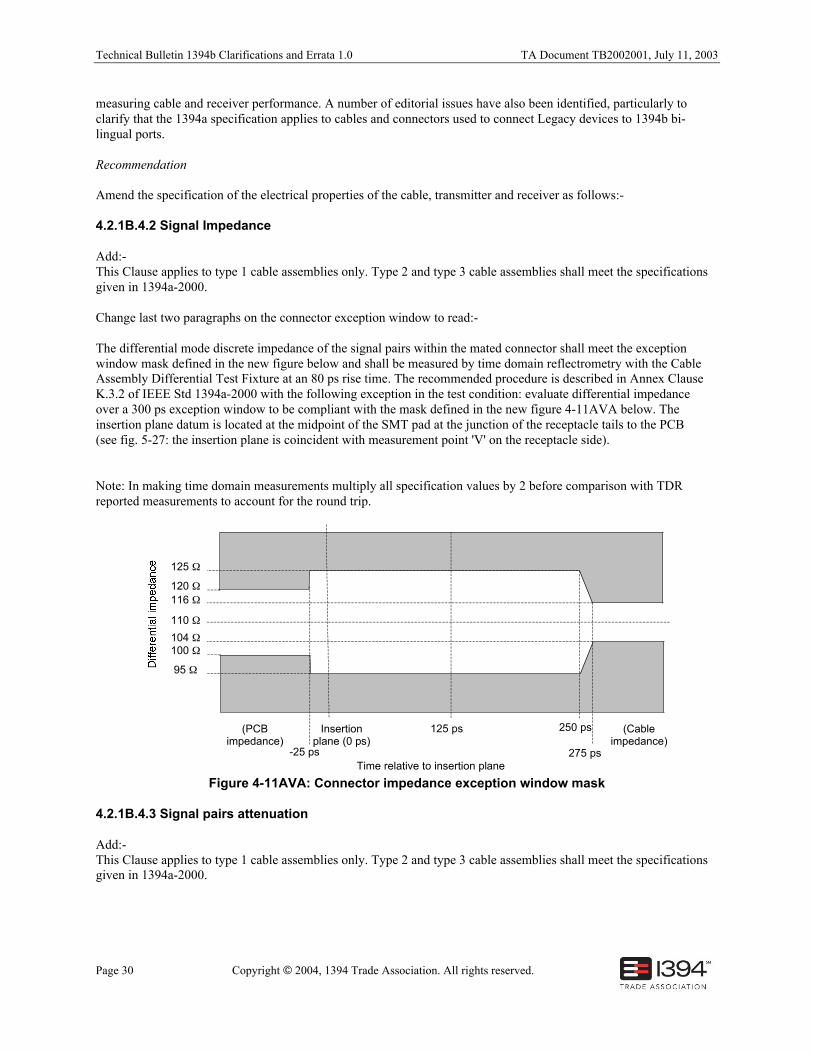
The differential mode discrete impedance of the signal pairs within the mated connector shall meet the exceptionwindow mask defined in the new figure below and shall be measured by time domain reflectrometry with the CableAssembly Differential Test Fixture at an 80 ps rise time. The recommended procedure is described in Annex ClauseK.3.2 of IEEE Std 1394a-2000 with the following exception in the test condition: evaluate differential impedanceover a 300 ps exception window to be compliant with the mask defined in the new figure 4-11AVA below. Theinsertion plane datum is located at the midpoint of the SMT pad at the junction of the receptacle tails to the PCB(see fig. 5-27: the insertion plane is coincident with measurement point 'V' on the receptacle side).
Note: In making time domain measurements multiply all specification values by 2 before comparison with TDRreported measurements to account for the round trip.
Insertionplane (0 ps)
-25 ps
125 ps 250 ps
275 ps
110 Ω
116 Ω
125 Ω
104 Ω
95 Ω
(PCBimpedance)
(Cableimpedance)
Time relative to insertion plane
120 Ω
100 Ω
Figure 4-11AVA: Connector impedance exception window mask
4.2.1B.4.3 Signal pairs attenuation
Add:-This Clause applies to type 1 cable assemblies only. Type 2 and type 3 cable assemblies shall meet the specificationsgiven in 1394a-2000.
TA Document TB2002001, July 11, 2003 Technical Bulletin 1394b Clarifications and Errata 1.0
Copyright © 2004, 1394 Trade Association. All rights reserved. Page 31
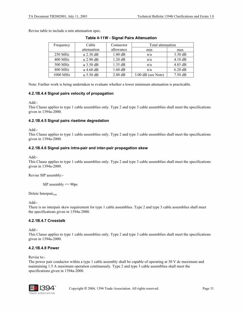
Revise table to include a min attenuation spec.
Table 4-11W - Signal Pairs AttenuationTotal attenuationFrequency Cable
attenuationConnectorallowance min max
250 MHz ≤ 2.30 dB 1.00 dB n/a 3.30 dB400 MHz ≤ 2.90 dB 1.20 dB n/a 4.10 dB500 MHz ≤ 3.50 dB 1.35 dB n/a 4.85 dB800 MHz ≤ 4.60 dB 1.60 dB n/a 6.20 dB
1000 MHz ≤ 5.50 dB 2.00 dB 3.00 dB (see Note) 7.50 dB
Note: Further work is being undertaken to evaluate whether a lower minimum attenuation is practicable.
4.2.1B.4.4 Signal pairs velocity of propagation
Add:-This Clause applies to type 1 cable assemblies only. Type 2 and type 3 cable assemblies shall meet the specificationsgiven in 1394a-2000.
4.2.1B.4.5 Signal pairs risetime degredation
Add:-This Clause applies to type 1 cable assemblies only. Type 2 and type 3 cable assemblies shall meet the specificationsgiven in 1394a-2000.
4.2.1B.4.6 Signal pairs intra-pair and inter-pair propagation skew
Add:-This Clause applies to type 1 cable assemblies only. Type 2 and type 3 cable assemblies shall meet the specificationsgiven in 1394a-2000.
Revise SIP assembly:-
SIP assembly <= 90ps
Delete Interpaircon
Add:-There is no interpair skew requirement for type 1 cable assemblies. Type 2 and type 3 cable assemblies shall meetthe specifications given in 1394a-2000.
4.2.1B.4.7 Crosstalk
Add:-This Clause applies to type 1 cable assemblies only. Type 2 and type 3 cable assemblies shall meet the specificationsgiven in 1394a-2000.
4.2.1B.4.8 Power
Revise to:-The power pair conductor within a type 1 cable assembly shall be capable of operating at 30 V dc maximum andmaintaining 1.5 A maximum operation continuously. Type 2 and type 3 cable assemblies shall meet thespecifications given in 1394a-2000.
Technical Bulletin 1394b Clarifications and Errata 1.0 TA Document TB2002001, July 11, 2003
Page 32 Copyright © 2004, 1394 Trade Association. All rights reserved.
9.1 Interfaces
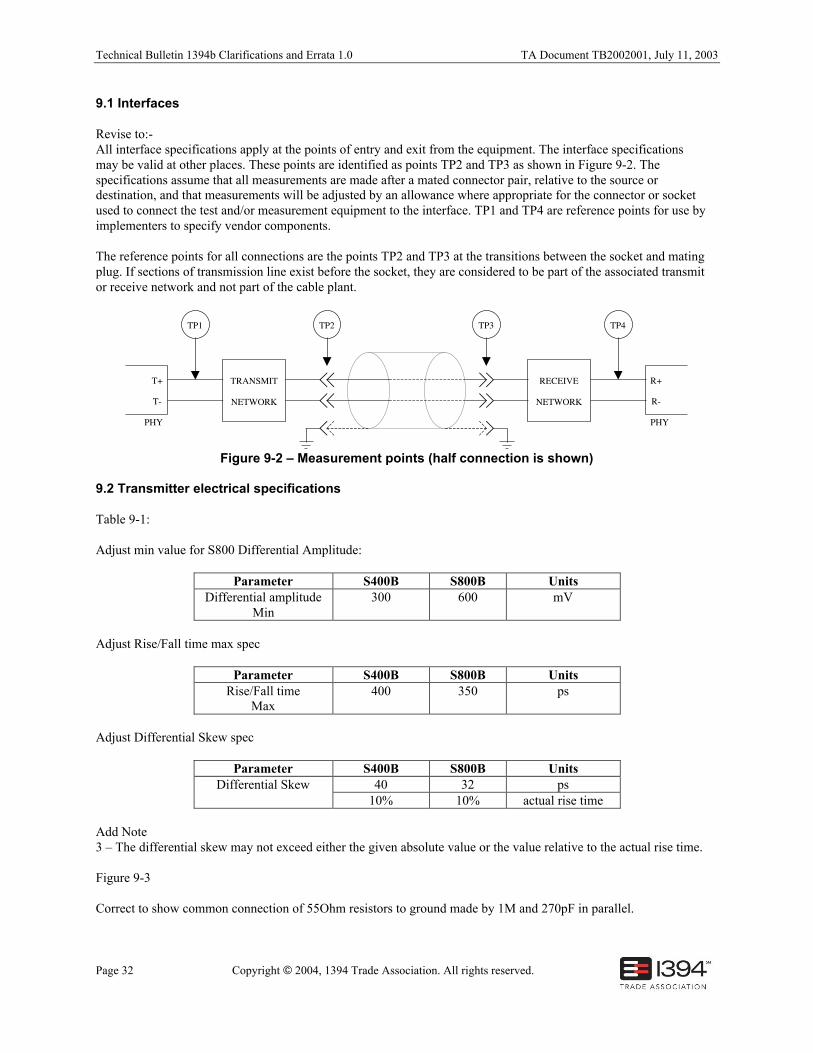
Revise to:-All interface specifications apply at the points of entry and exit from the equipment. The interface specificationsmay be valid at other places. These points are identified as points TP2 and TP3 as shown in Figure 9-2. Thespecifications assume that all measurements are made after a mated connector pair, relative to the source ordestination, and that measurements will be adjusted by an allowance where appropriate for the connector or socketused to connect the test and/or measurement equipment to the interface. TP1 and TP4 are reference points for use byimplementers to specify vendor components.
The reference points for all connections are the points TP2 and TP3 at the transitions between the socket and matingplug. If sections of transmission line exist before the socket, they are considered to be part of the associated transmitor receive network and not part of the cable plant.
T+
T-
TRANSMIT
NETWORK
TP1 TP2
R+
R-
TP3 TP4
PHY PHY
RECEIVE
NETWORK
Figure 9-2 – Measurement points (half connection is shown)
9.2 Transmitter electrical specifications
Table 9-1:
Adjust min value for S800 Differential Amplitude:
Parameter S400B S800B UnitsDifferential amplitude
Min300 600 mV
Adjust Rise/Fall time max spec
Parameter S400B S800B UnitsRise/Fall time
Max400 350 ps
Adjust Differential Skew spec
Parameter S400B S800B Units40 32 psDifferential Skew
10% 10% actual rise time
Add Note3 – The differential skew may not exceed either the given absolute value or the value relative to the actual rise time.
Figure 9-3
Correct to show common connection of 55Ohm resistors to ground made by 1M and 270pF in parallel.
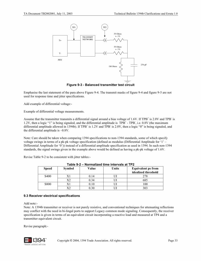
TA Document TB2002001, July 11, 2003 Technical Bulletin 1394b Clarifications and Errata 1.0
Copyright © 2004, 1394 Trade Association. All rights reserved. Page 33
T+
T-
PHY
TRANSMITNETWORK
TP1
55 Ohms+- 1%
55 Ohms+- 1%
1M Ohms270 pF
TP2
Figure 9-3 - Balanced transmitter test circuit
Emphasise the last statement of the para above Figure 9-4. The transmit masks of figure 9-4 and figure 9-5 are notused for response time and jitter specifications.
Add example of differential voltage:-
Example of differential voltage measurements.
Assume that the transmitter transmits a differential signal around a bias voltage of 1.6V. If TPB+ is 2.0V and TPB- is1.2V, then a logic “1” is being signaled, and the differential amplitude is TPB+ - TPB-, i.e. 0.8V (the maximumdifferential amplitude allowed in 1394b). If TPB+ is 1.2V and TPB- is 2.0V, then a logic “0” is being signaled, andthe differential amplitude is –0.8V.
Note: Care should be taken when comparing 1394 specifications to non-1394 standards, some of which specifyvoltage swings in terms of a pk-pk voltage specification (defined as modulus (Differential Amplitude for ‘1’ –Differential Amplitude for ‘0’)) instead of a differential amplitude specification as used in 1394. In such non-1394standards, the signal swings given in the example above would be defined as having a pk-pk voltage of 1.6V.
Revise Table 9-2 to be consistent with jitter tables:-
Table 9-2 – Normalized time intervals at TP2Speed Symbol Value Units Equivalent ps from
idealized thresholdX1 0.14 UI 278S400X2 0.34 UI 685X1 0.10 UI 100S800X2 0.30 UI 303
9.3 Receiver electrical specifications
Add note:-Note: A 1394b transmitter or receiver is not purely resistive, and conventional techniques for attenuating reflectionsmay conflict with the need in bi-lingal ports to support Legacy common mode signaling. Consequently, the receiverspecification is given in terms of an equivalent circuit incorporating a reactive load and measured at TP4 and atransmitter equivalent circuit.
Revise paragraph:-
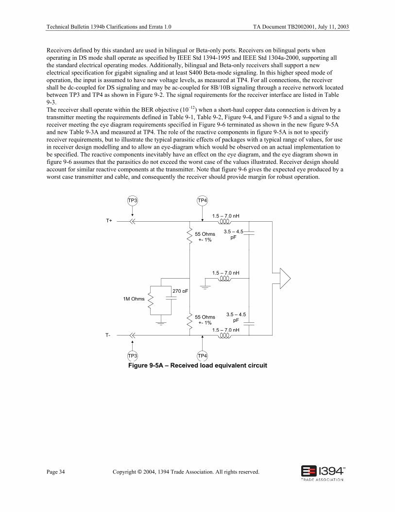
Technical Bulletin 1394b Clarifications and Errata 1.0 TA Document TB2002001, July 11, 2003
Page 34 Copyright © 2004, 1394 Trade Association. All rights reserved.
Receivers defined by this standard are used in bilingual or Beta-only ports. Receivers on bilingual ports whenoperating in DS mode shall operate as specified by IEEE Std 1394-1995 and IEEE Std 1304a-2000, supporting allthe standard electrical operating modes. Additionally, bilingual and Beta-only receivers shall support a newelectrical specification for gigabit signaling and at least S400 Beta-mode signaling. In this higher speed mode ofoperation, the input is assumed to have new voltage levels, as measured at TP4. For all connections, the receivershall be dc-coupled for DS signaling and may be ac-coupled for 8B/10B signaling through a receive network locatedbetween TP3 and TP4 as shown in Figure 9-2. The signal requirements for the receiver interface are listed in Table9-3.The receiver shall operate within the BER objective (10–12) when a short-haul copper data connection is driven by atransmitter meeting the requirements defined in Table 9-1, Table 9-2, Figure 9-4, and Figure 9-5 and a signal to thereceiver meeting the eye diagram requirements specified in Figure 9-6 terminated as shown in the new figure 9-5Aand new Table 9-3A and measured at TP4. The role of the reactive components in figure 9-5A is not to specifyreceiver requirements, but to illustrate the typical parasitic effects of packages with a typical range of values, for usein receiver design modelling and to allow an eye-diagram which would be observed on an actual implementation tobe specified. The reactive components inevitably have an effect on the eye diagram, and the eye diagram shown infigure 9-6 assumes that the parasitics do not exceed the worst case of the values illustrated. Receiver design shouldaccount for similar reactive components at the transmitter. Note that figure 9-6 gives the expected eye produced by aworst case transmitter and cable, and consequently the receiver should provide margin for robust operation.
T+
T-
55 Ohms+- 1%
1M Ohms
270 pF
TP4
1.5 – 7.0 nH
1.5 – 7.0 nH
3.5 – 4.5pF
55 Ohms+- 1%
1.5 – 7.0 nH
3.5 – 4.5pF
TP4TP3
TP3
Figure 9-5A – Received load equivalent circuit
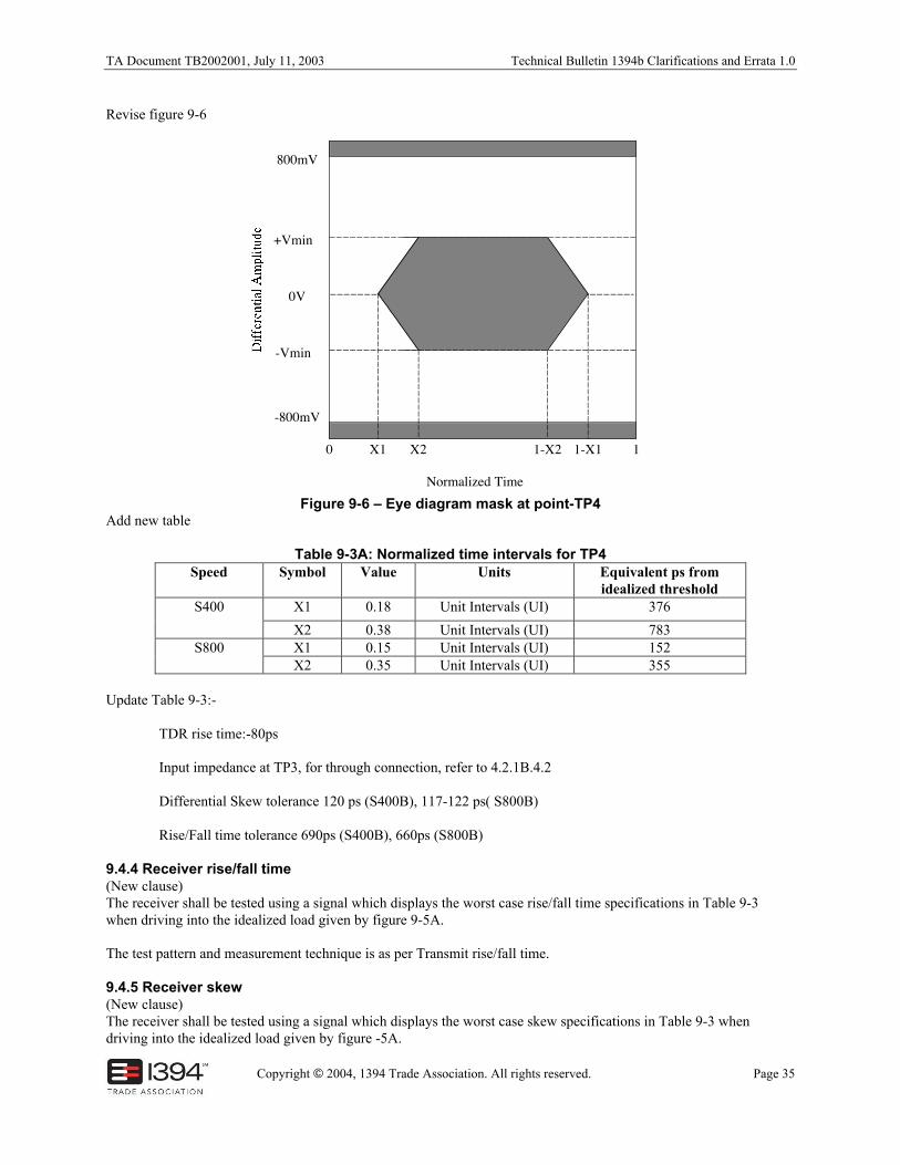
TA Document TB2002001, July 11, 2003 Technical Bulletin 1394b Clarifications and Errata 1.0
Copyright © 2004, 1394 Trade Association. All rights reserved. Page 35
Revise figure 9-6
X1 X2 1-X2 1-X1
800mV
+Vmin
0V
-Vmin
-800mV
Normalized Time
0 1
Figure 9-6 – Eye diagram mask at point-TP4Add new table
Table 9-3A: Normalized time intervals for TP4Speed Symbol Value Units Equivalent ps from
idealized thresholdX1 0.18 Unit Intervals (UI) 376S400
X2 0.38 Unit Intervals (UI) 783X1 0.15 Unit Intervals (UI) 152S800X2 0.35 Unit Intervals (UI) 355
Update Table 9-3:-
TDR rise time:-80ps
Input impedance at TP3, for through connection, refer to 4.2.1B.4.2
Differential Skew tolerance 120 ps (S400B), 117-122 ps( S800B)
Rise/Fall time tolerance 690ps (S400B), 660ps (S800B)
9.4.4 Receiver rise/fall time(New clause)The receiver shall be tested using a signal which displays the worst case rise/fall time specifications in Table 9-3when driving into the idealized load given by figure 9-5A.
The test pattern and measurement technique is as per Transmit rise/fall time.
9.4.5 Receiver skew(New clause)The receiver shall be tested using a signal which displays the worst case skew specifications in Table 9-3 whendriving into the idealized load given by figure -5A.
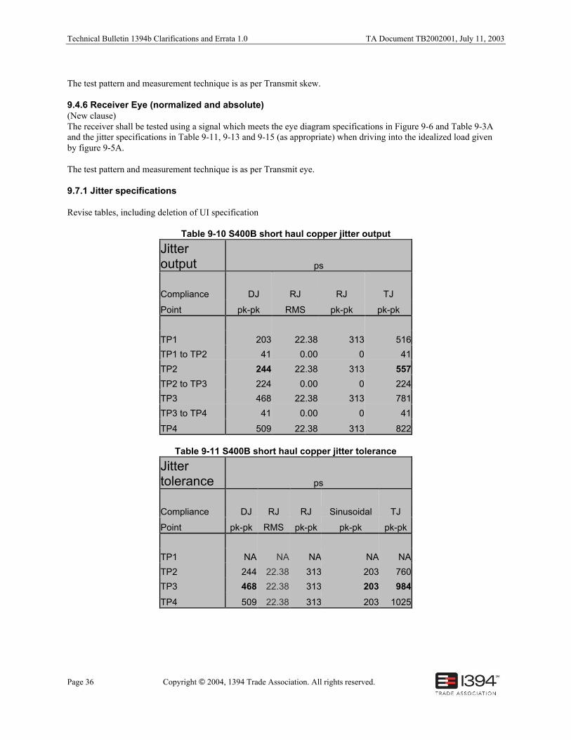
Technical Bulletin 1394b Clarifications and Errata 1.0 TA Document TB2002001, July 11, 2003
Page 36 Copyright © 2004, 1394 Trade Association. All rights reserved.
The test pattern and measurement technique is as per Transmit skew.
9.4.6 Receiver Eye (normalized and absolute)(New clause)The receiver shall be tested using a signal which meets the eye diagram specifications in Figure 9-6 and Table 9-3Aand the jitter specifications in Table 9-11, 9-13 and 9-15 (as appropriate) when driving into the idealized load givenby figure 9-5A.
The test pattern and measurement technique is as per Transmit eye.
9.7.1 Jitter specifications
Revise tables, including deletion of UI specification
Table 9-10 S400B short haul copper jitter output
Jitteroutput ps
Compliance DJ RJ RJ TJ
Point pk-pk RMS pk-pk pk-pk
TP1 203 22.38 313 516
TP1 to TP2 41 0.00 0 41
TP2 244 22.38 313 557
TP2 to TP3 224 0.00 0 224
TP3 468 22.38 313 781
TP3 to TP4 41 0.00 0 41
TP4 509 22.38 313 822
Table 9-11 S400B short haul copper jitter tolerance
Jittertolerance ps
Compliance DJ RJ RJ Sinusoidal TJ
Point pk-pk RMS pk-pk pk-pk pk-pk
TP1 NA NA NA NA NA
TP2 244 22.38 313 203 760
TP3 468 22.38 313 203 984
TP4 509 22.38 313 203 1025
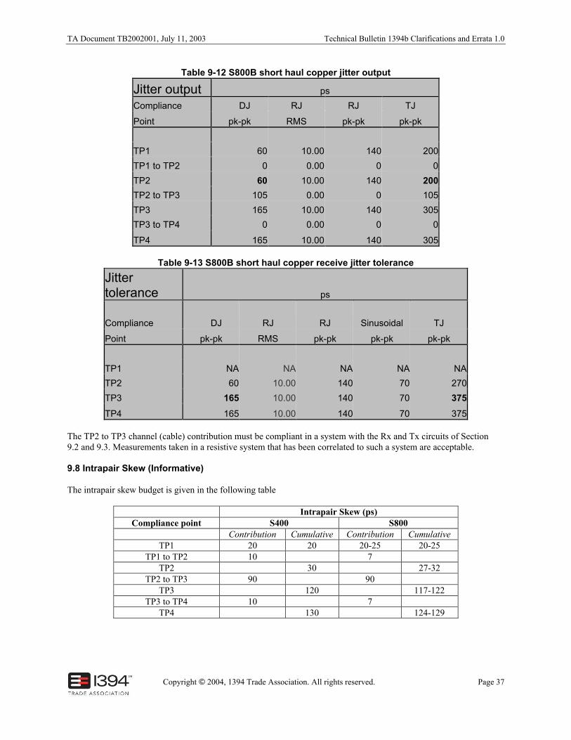
TA Document TB2002001, July 11, 2003 Technical Bulletin 1394b Clarifications and Errata 1.0
Copyright © 2004, 1394 Trade Association. All rights reserved. Page 37
Table 9-12 S800B short haul copper jitter output
Jitter output ps
Compliance DJ RJ RJ TJ
Point pk-pk RMS pk-pk pk-pk
TP1 60 10.00 140 200
TP1 to TP2 0 0.00 0 0
TP2 60 10.00 140 200
TP2 to TP3 105 0.00 0 105
TP3 165 10.00 140 305
TP3 to TP4 0 0.00 0 0
TP4 165 10.00 140 305
Table 9-13 S800B short haul copper receive jitter tolerance
Jittertolerance ps
Compliance DJ RJ RJ Sinusoidal TJ
Point pk-pk RMS pk-pk pk-pk pk-pk
TP1 NA NA NA NA NA
TP2 60 10.00 140 70 270
TP3 165 10.00 140 70 375
TP4 165 10.00 140 70 375
The TP2 to TP3 channel (cable) contribution must be compliant in a system with the Rx and Tx circuits of Section9.2 and 9.3. Measurements taken in a resistive system that has been correlated to such a system are acceptable.
9.8 Intrapair Skew (Informative)
The intrapair skew budget is given in the following table
Intrapair Skew (ps)Compliance point S400 S800
Contribution Cumulative Contribution CumulativeTP1 20 20 20-25 20-25
TP1 to TP2 10 7TP2 30 27-32
TP2 to TP3 90 90TP3 120 117-122
TP3 to TP4 10 7TP4 130 124-129

Technical Bulletin 1394b Clarifications and Errata 1.0 TA Document TB2002001, July 11, 2003
Page 38 Copyright © 2004, 1394 Trade Association. All rights reserved.
4.37 Connector Speci fication clarifications
DescriptionVarious clarifications are needed to the connector specification, in particular to clarify the true proportions, to clarifycircuit numbers, and to remove notes that have been erroneously carried over from the 1394a specification.
RecommendationFigure 4-11N - Beta Plug Body with Overmold. Clarify the drawing as follows:-
Revise this drawing to reflect the true proportions of this plug. Also, enhance the pictorial that defines the circuitnumbers, add the label “CIRCUIT NUMBERS,” and add “SEE DETAIL A,” and relocate Section S-S, and revisethe definition of Section Z-Z. Remove Note 4, which is a vestige from the 1394-1995 specification that originallydefined two chamfers that aren’t used in the 1394b. Add the 3.10mm Basic dimension, which is redundant, but thisshould help the readability. Make these same corresponding changes to Figure 5-2.
Figure 4-11N – Beta Plug Body with Overmold

TA Document TB2002001, July 11, 2003 Technical Bulletin 1394b Clarifications and Errata 1.0
Copyright © 2004, 1394 Trade Association. All rights reserved. Page 39
Figure 4-11P - Beta/Bilingual Plug Interface Detail A. Correct a drafting error: revise the leader line (from theR0.35 MAX dimension) from a broken line to a solid line.
Figure 4-11P – Beta/Bilingual Plug Interface Detail A
Figure 4-11S - Beta Socket Body. Avoid an overly restrictive requirement on the PCB standoffs.
Revise the 0.30mm +/- 0.03mm dimension to be 0.27mm MIN. Make this same corresponding change to Figure 5-8.
Figure 4-11S – Beta Socket Body
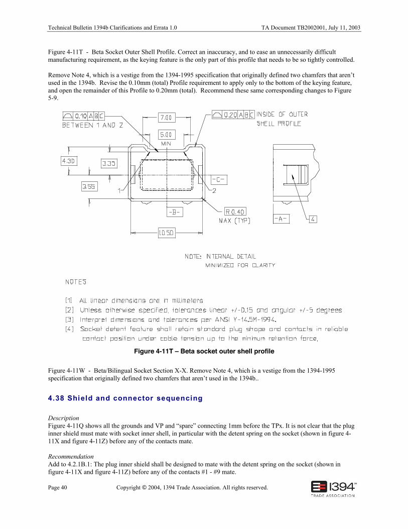
Technical Bulletin 1394b Clarifications and Errata 1.0 TA Document TB2002001, July 11, 2003
Page 40 Copyright © 2004, 1394 Trade Association. All rights reserved.
Figure 4-11T - Beta Socket Outer Shell Profile. Correct an inaccuracy, and to ease an unnecessarily difficultmanufacturing requirement, as the keying feature is the only part of this profile that needs to be so tightly controlled.
Remove Note 4, which is a vestige from the 1394-1995 specification that originally defined two chamfers that aren’tused in the 1394b. Revise the 0.10mm (total) Profile requirement to apply only to the bottom of the keying feature,and open the remainder of this Profile to 0.20mm (total). Recommend these same corresponding changes to Figure5-9.
Figure 4-11T – Beta socket outer shell profile
Figure 4-11W - Beta/Bilingual Socket Section X-X. Remove Note 4, which is a vestige from the 1394-1995specification that originally defined two chamfers that aren’t used in the 1394b..
4.38 Shield and connector sequencing
DescriptionFigure 4-11Q shows all the grounds and VP and “spare” connecting 1mm before the TPx. It is not clear that the pluginner shield must mate with socket inner shell, in particular with the detent spring on the socket (shown in figure 4-11X and figure 4-11Z) before any of the contacts mate.
RecommendationAdd to 4.2.1B.1: The plug inner shield shall be designed to mate with the detent spring on the socket (shown infigure 4-11X and figure 4-11Z) before any of the contacts #1 - #9 mate.