table of contents 1 - systema ptw · 2 installation manual for the professional training weapon...
TRANSCRIPT
2
Installation Manual for the Professional Training Weapon Version Up Kit
We would like to take this opportunity to thank you for your recent purchase of the SYSTEMA ProfessionalTraining Weapon Version Up Kit. Let us begin by explaining the general features of the Version Up Kit. 1. Abbreviations of commonly used terms.
P.T.W.®: Professional Training Weapon S.E.C.U.®: SYSTEMA Electronic Control Unit (also referred to as the Core System)
2. The purpose of Version-Up Kit and its variants of the Version Up Kits are to upgrade the first P.T.W.
series that have been sold from 2004 to match to today’s standards. The five major improvements arelisted below (A~E). Depending on the contents of which, the Version Up Kits differ by three types. Thefirst released M16-A3 contains the most changes therefore is considered the most extreme of the threevariants; the difference of the other two variations lay in the difference in the model of the P.T.W.therefore has subtle changes to the components. The main product line of the P.T.W. is recognized asthose sold in 2004, since all variations were released that year.
Version Up Kit Model Variations:
a) Version Up Kit M16-A3 (2004 model) b) Version Up Kit M4-A1 (2004 model) c) Version Up Kit M16-A2 (2004 model)
3. How to distinguish between a 2004 and a 2005 model P.T.W.
・Field Stripable Receiver ・The Cylinder unit may be removed ・The outer diameter on the tip of the cylinder unit is different in size. *
* The 2004 model has an outer diameter of 7.1mm while the 2005 model has an outer diameter of 6.5mm.
4. Improvements made to the P.T.W. P.T.W. Core System and Switch Device Variations:
・Model #2004-3 (2004 model designed for M16-A3 version) ・Model #2004-7 (2004 model designed for M4-A1 & M16-A2) ・Model #2004-10 (Currently in production for all models)
SYSTEMA
2004 Model
M4-A1 2004 Model
M16-A2 2004 Model
M16-A3

SYSTEMA Co.
A) Developments on the S.E.C.U. and the P.T.W. Switch Device.
It can be said that the fundamental improvement to the P.T.W. stems from the evolution of both the S.E.C.U. as well as the
Switch Device. Excluding a particular type, there were a total of three versions of the S.E.C.U. as well as the Switch Device
developed. Within those, model #2004-3 (which was sold in 2004) was designed exclusively for the M16-A3 design. 2004-7
(which was also sold in 2004) was designed for the M4-A1 version as well as the M16-A2 version (for that year). We would
like to focus on these models. In other words, since the third model is the latest version we would like to have those with
either i. or ii. models to exchange it to model iii. (Which is currently in production). Please refer to the accompanied
CD-Rom for details on step-by-step instructions with warnings in exchanging the core system.
B) Developments toward the mechanism of chambering a round.
It was one of our more important projects to develop a reliable round chambering system that is not affected by a high rate of fire. Below describes three particular components that were replaced for improvement. Of these, the most important is the change of the nozzle section. In the latest version, the outer diameter of this piece is smaller, therefore making it easy to distinguish between this and the earlier models. Along with the nozzle, the Hop Chamber Base has also been changed. In order to replace the Hop Chamber Base, knowledge in taking apart and putting together the inner barrel section is required, which is considered one of the more challenging tasks. Please refer to the accompanied manual while carefully performing this task. Although this is not listed in the official kit manual, as a one-point advice we recommend that you lube the magazine catch periodically to improve the performance.
Recap on improvements to the chambering section: a) Changes to the nozzle b) Design change to the Hop Chamber Base c) Magazine catch one-point advice for improved performance
C) Developments to the Grip End. The smooth rotation of the motor is the foundation of an AEG. The grip end of the 2004 model was designed with a very tight set up. However with this design, when the four screws that secure the grip-end are tightened, the grip-end slightly rides up the grip causing unnecessary stress to the motor. Therefore the grip-end was designed slightly smaller for the 2005 model. The result of the change saw the position of the motor acting independently from the grip allowing a more smooth cycle of the motor.
D) Developments to the Trigger Mechanism. The Trigger Mechanism has been redesigned to replicate the trigger stroke of a real firearm.
E) Development to the Selector Lever (exclusively for the M16-A3 version). Praised by many with the newest model, many thought when the first series of the A3 were sold the selector lever felt sluggish. However in order to upgrade to the current design which employs a bearing for a smooth click of the selector; it will require an extensive knowledge of taking apart and putting together the gear box as well as changing out other components.

Version Up Kit Installation Manual -Table of Contents-
1.Take Down・・・・・・・・・・・・・・・・・・・・・・・・・・・・・・・・・・・・・・・・・・・・・・・・・・・・・・・・・・・・・・・・・・ P1
2.Replacement of the Cylinder Head Assembly・・・・・・・・・・・・・・・・・・・・・・・・・・・・・・・・・・・・・・・ P1
① Removal of the Spring Guide Assembly(ASS-CU-06)・・・・・・・・・・・・・・・・・・・・・・・・・・・・・・・・・ P1
② Replacement of the Cylinder Head Assembly(ASS-CU-01)・・・・・・・・・・・・・・・・・・・・・・・・・・・・・ P1
Replacement of the Cylinder Head Assembly(ASS-CU-01)
3.Replacement of the Charging Handle(ASS-UR-01)・・・・・・・・・・・・・・・・・・・・・・・・・・・・・・・・・・・ P2
4.Disassembly of the Inner Barrel Assembly(ASS-BR-04 / ASS-BR-05)・・・・・・・・・・・・・・・・・・・ P2
① Removal of the Barrel Key(BR-022)・・・・・・・・・・・・・・・・・・・・・・・・・・・・・・・・・・・・・・・・・・・・・・ P2
② Removal and replacement of the HOP Chamber Base(BR-031-M4 / BR-031-A2)・・・・・・・・・・・ P2
③ Disassemble of the HOP camber Base・・・・・・・・・・・・・・・・・・・・・・・・・・・・・・・・・・・・・・・・・・・・ P3
④ Warnings for Assembly a) Assembly of the Chamber Sleeve(BR-030)・・・・・・・・・・・・・・・・・・・・・・・・・・・・・・・・・・・・・ P3
b) Assembly of the Air-Seal Packing(BR-029)・・・・・・・・・・・・・・・・・・・・・・・・・・・・・・・・・・・・・ P3
c) Lubing the Inner Barrel・・・・・・・・・・・・・・・・・・・・・・・・・・・・・・・・・・・・・・・・・・・・・・・・・・・・・ P3
d) Assembly of the HOP Adjuster(BR-026)・・・・・・・・・・・・・・・・・・・・・・・・・・・・・・・・・・・・・・・・P3
e) Lubing the HOP Chamber Base・・・・・・・・・・・・・・・・・・・・・・・・・・・・・・・・・・・・・・・・・・・・・・ P3
f) Assembly of the Inner Barrel・・・・・・・・・・・・・・・・・・・・・・・・・・・・・・・・・・・・・・・・・・・・・・・・ P4
g) Assembly of the Barrel Key・・・・・・・・・・・・・・・・・・・・・・・・・・・・・・・・・・・・・・・・・・・・・・・・・・ P4
h) Confirm the function of HOP Adjustment・・・・・・・・・・・・・・・・・・・・・・・・・・・・・・・・・・・・・・・ P4
Replacement of the HOP Chamber Base(BR-033)
HOP Adjuster(BR-26,BR-027,BR-028)
Adjuster Cushion(BR-025 set of 2)
5.Replacement of Parts inside the Gear Box
①Removal of the Bolt Stop(LR-011)・・・・・・・・・・・・・・・・・・・・・・・・・・・・・・・・・・・・・・・・・・・・・・・・・・ P5
Replacement of the Trigger(GB-014) S.E.C.U. (EL-001) Internal Sector Gear(GB-007) Selector Switch Board(EL-002)・・・・・・・・・・・・・・・・・・・・・・・・・・ A3 Selector Lever(GB-018)・・・・・・・・・・・・・・・・・・・・・・・・・・・・・・・・・ A3 Selector Click Ball Screw(GB-019) ・・・・・・・・・・・・・・・・・・・・・・・ A3 Selector Click Ball Spring(GB-020)・・・・・・・・・・・・・・・・・・・・・・・ A3 Selector Click Ball(GB-021)・・・・・・・・・・・・・・・・・・・・・・・・・・・・・・ A3 Gear Case Left Side(GB-002)・・・・・・・・・・・・・・・・・・・・・・・・・・・・・ A3

② Removal of the S.E.C.U.(EL-001)・・・・・・・・・・・・・・・・・・・・・・・・・・・・・・・・・・・・・・・・・・・・・・・・・ P5
③ Removal of the Selector Lever(GB-018)・・・・・・・・・・・・・・・・・・・・・・・・・・・・・・・・・・・・・・・・・ P5
④ Removal of the Set Screw for Gear Box(GB-025)・・・・・・・・・・・・・・・・・・・・・・・・・・・・・・・ P5
⑤ Removal of the Gear Box・・・・・・・・・・・・・・・・・・・・・・・・・・・・・・・・・・・・・・・・・・・・・・・・・・・・・・・・ P5
⑥ Disassembly of the Gear Box・・・・・・・・・・・・・・・・・・・・・・・・・・・・・・・・・・・・・・・・・・・・・・・・・・・・・ P6
a) Removal of the Fixing Screw for Gear Case(GB-023 set of 5)・・・・・・・・・・・・・・・・・・・・・・ P6
b) Replacement of the Trigger・・・・・・・・・・・・・・・・・・・・・・・・・・・・・・・・・・・・・・・・・・・・・・・・・・・ P6
Beyond this section is exclusively for the M16-A3
c) Removal of the Helical and the Sun Gear(GB-005)・・・・・・・・・・・・・・・・・・・・・・・・・・・・・・・・・ P6
d) Removal of the Bevel and the Helical Gear(GB-003)・・・・・・・・・・・・・・・・・・・・・・・・・・・・・・・ P6
e) Removal of the Bearing Plate(GB-009)・・・・・・・・・・・・・・・・・・・・・・・・・・・・・・・・・・・・・・・・・・ P7
f) Replacement of the Internal Sector Gear(GB-007)・・・・・・・・・・・・・・・・・・・・・・・・・・・・・・・・・ P7
g) Removal of the Planetary Gear(GB-008-L / GB-008-S)・・・・・・・・・・・・・・・・・・・・・・・・・・・・・ P7
h) Removal of the Selector Rack Gear(GB-022)・・・・・・・・・・・・・・・・・・・・・・・・・・・・・・・・・・・・ P7
i) Replacement of the Selector Switch Board(EL-002)・・・・・・・・・・・・・・・・・・・・・・・・・・・・・・・・ P7
j) Replacement of the Gear Case Left Side(GB-002)・・・・・・・・・・・・・・・・・・・・・・・・・・・・・・・・・・ P7
⑦ Warnings during Assembly a) Installation of the Sun Gear Shaft(GB-012)and the Sun Gear shaft Bearing(GB-013)・・・・・・ P8
b)Verification of the Gear rotation ・・・・・・・・・・・・・・・・・・・・・・・・・・・・・・・・・・・・・・・・・・・・・・・ P8
c) Regards to sealing the Gear Case with the Set Screws・・・・・・・・・・・・・・・・・・・・・・・・・・・・・・・ P8
d)Replacement of the S.E.C.U.・・・・・・・・・・・・・・・・・・・・・・・・・・・・・・・・・・・・・・・・・・・・・・・・・・・ P8
e)Assembly of the Gear Box・・・・・・・・・・・・・・・・・・・・・・・・・・・・・・・・・・・・・・・・・・・・・・・・・・・・ P9
f)Replacement of the Selector Lever・・・・・・・・・・・・・・・・・・・・・・・・・・・・・・・・・・・・・・・・・・・・・・ P9
6.Replacement of the Switch Device(M4-A1 Model)
① Removal of the Grip End(LR-024)・・・・・・・・・・・・・・・・・・・・・・・・・・・・・・・・・・・・・・・・・・・・・・・・ P10
② Removal of the Grip(LR-022)・・・・・・・・・・・・・・・・・・・・・・・・・・・・・・・・・・・・・・・・・・・・・・・・・・・・ P10
③ Removal of the Motor Code・・・・・・・・・・・・・・・・・・・・・・・・・・・・・・・・・・・・・・・・・・・・・・・・・・・・・ P10
④ Removal of the Stock Tube Cap(SST-015)・・・・・・・・・・・・・・・・・・・・・・・・・・・・・・・・・・・・・・・・・・ P11
⑤ Removal of the Stock Tube Nut(SST-012)・・・・・・・・・・・・・・・・・・・・・・・・・・・・・・・・・・・・・・・・・・ P11
⑥ Removal of the Switch Device(EL-003-M4)・・・・・・・・・・・・・・・・・・・・・・・・・・・・・・・・・・・・・・・・・ P11
7.Replacement of the Switch Device(M16-A2 / A3 Model)
① Removal of the Butt Plate Assembly・・・・・・・・・・・・・・・・・・・・・・・・・・・・・・・・・・・・・・・・・・・・・・・ P12
② Removal of the Stock Pipe End Screw(FST-019)・・・・・・・・・・・・・・・・・・・・・・・・・・・・・・・・・・・・・ P12
③ Removal of the Fixed Stock(FST-005)・・・・・・・・・・・・・・・・・・・・・・・・・・・・・・・・・・・・・・・・・・・・・ P12
④ Removal of the Switch Device(EL-003-A2)・・・・・・・・・・・・・・・・・・・・・・・・・・・・・・・・・・・・・・・・・ P12
Replacement of the Grip End(LR-024) Switch Device(EL-003-M4 / EL-003-A2)

1
③ Replacement of the Cylinder Head Assembly
(ASS-CU-01)
Using a reversed 22mm wrench to remove the item. (See
illustration)
Warning
Depending on some of the versions there may be some
adhesive that seals the cylinder head.
If it does not come apart with strength please use a burner
(or propane torch) and heat the tip area of the cylinder case
(to melt the adhesive), then try again.
2. Replacement of the Cylinder Head Assembly
① Removal of the Cylinder Unit
Pulling on the charging handle will remove the cylinder unit
from the upper receiver.
② Removal of the Spring Guide Assembly (ASS-CU-06)
Using the special wrench (as seen in the illustration) to
remove the item.
②Holding onto the carrying handle point the stock down
while pulling on the upper receiver. (See illustration)
1.Take Down
①Using a pin punch with a diameter of 5mm or less push
the take down pin through to the take down pin stopper
piece. (See illustration)
Warning
When pushing the take down pin please take caution to stop
when it reaches the stopper pin.
Failure to do so by forcefully pushing through the pin past
the stopper pin may damage the lower receiver.
Please proceed with caution when doing this procedure.
-1-

1
②Removal and replacement of the Hop Chamber Base.
Removal of the Hop Chamber Base can be done as seen in
this illustration and replace this piece with the part that is
enclosed with the kit.
During this procedure if the Barrel Key does not float up,
use a snap ring plier (as seen in the illustration) and pull the
Barrel Key straight out.
4. Disassembly of the Inner Barrel Assembly (ASS-BR-01 /
ASS-BR-05).
The purpose of this section is to disassemble the Inner
Barrel Assembly to replace the Hop Chamber Base.
This procedure has a high level of difficulty, therefore
requires a high level of expertise.
Please follow the instructions in the manual and proceed
with caution.
①Removal of the Barrel Key (BR-022).
Please take a look at the illustration.
As you hold the barrel with the flash hider side down,
lightly tap the hole with a plastic coated hammer where the
nozzle of the Hop Chamber Base goes in.
3. Removal of the Charging Handle (ASS-UR-01)
Please refer to the illustration as you are doing this
procedure.
Once you point the item down you can pull to remove.
-2-

1
e) Lubing the Hop Chamber Base.
Apply an equal amount of Cylinder Grease to the Hop
Chamber Base except for the inside of the Chamber
Base.
d) Assembly of the Hop Adjuster (BR-026)
Assemble the Hop Adjuster to the Inner Barrel as seen
in the illustration.
④Warnings for Assembly.
a) Assembly of the Chamber Sleeve (BR-030)
Securing the Chamber Sleeve to the Inner Barrel.
b) Assembly of the Air-Seal Packing (BR-029)
At the same time secure the Air Seal Packing to the
Inner Barrel.
c) Lubing the Inner Barrel
As seen in the illustration, apply a thin layer of
cylinder grease to the area where the Hop Adjuster is
located.
③ Disassemble of the Hop Camber Base
Removal of the Camber Packing(BR-023),Chamber Packing
Base(BR-024),Hop Adjuster(BR-026,BR-027,BR-028)
,Adjuster Cushion(set of two),and Air Seal Packing(BR-029)
can be done as seen in illustration.
-3-

1
-4-
h) Confirm the function of the Hop Adjustment.
Please refer to the Illustration.
Remove the Hop Adjuster Screw, using a pin punch
push it from below you can confirm the movement of
the Hop Adjuster as it moves up and down.
In the event that it snags in movement, unfortunately
please redo the assembly of this section.
g) Assembly of the Barrel Key
Insert the Barrel Key to the Hop Chamber Base.
If the Barrel Key, Hop Chamber Base, and the Inner
Barrel lines up perfectly with their appropriate holes
force will not be required to put it together; all it would
take is a little strength to assemble.
Never use excessive force in any of these procedures.
f) Assembly of the Inner Barrel.
Assemble the Inner barrel to the Hop Chamber Base as
seen in the illustration.

1
④ Removal of the Gear Box Set Screw (GB-025)
Remove the piece gear box set screw(GB-025 set of two).
⑤ Removal of the Gear Box
There is a certain nack to take apart the Gear Box.
Using a plastic hammer gently tap the area where the stock
tube fits into the lower receiver, then the gear box should
lift up slightly.
We do not recommend any other method of removing the
gear box.
③ Removal of the Selector Lever (GB-018)
The 2004 M16-A3 model contained M3 sized hollow
setscrews for the upper area of the gearbox, once those are
removed the selector lever can be removed.
For subsequent models, both the selector click ball screw
(GB-019)and the selector click ball spring(GB-020) must be
removed in order to remove the selector lever.
② Removal of the S.E.C.U. (EL-001) (SYSTEMA
Electronic Control Unit).
Please see the illustration.
Please use the rubber gloves that comes with this kit.
The Control Unit is highly susceptible to static electricity.
5. Replacement of Parts inside the Gear Box.
In order to replace the trigger, you must remove the gear
box from the lower receiver first.
Below is a step by step on this procedure.
① Removal of the Bolt Stop (LR-011)
Using a pin punch push the Bolt Stop Set Pin(LR-013) and
pull out the pin.
-5-

1
d) Remove the Bevel and the Helical Gear(GB-003)
from its housing.
At this stage there are shims located on the Bevel Gear;
please take caution not to lose any of the shims.
(GB-024)
c) Remove the Helical and the Sun Gear(GB-005)
from its housing.
b) Replacement of the Trigger.(GB-014)
Remove both the Trigger and the Trigger spring.
(GB-015)
Replace the trigger with the version up kit piece.
When installing the Trigger please confirm that the
trigger spring rests in the prescribed hole within the
Gear Box Case.
Please refer to the Illustration.
Beyond this section is exclusively for the M16-A3
⑥Disassembly of the Gear Box
a) Remove the 5 pieces Fixing Screw for the Gear
Case.(GB-023 set of five)
-6-

1
i) Remove the Selector Rack(GB-022) from its
housing.
j) Remove the Selector Switch Board(EL-002) from
its housing.
Using a cutter knife, taking caution not to damage the
cord; gently insert the knife between the crack and
slowly pry open the housing.
k) Up to this point, the L Gear Case is empty, therefore
the kit will replace the internal components.
g) Removal of the Planetary Gear (GB-008-L /
GB-008-S)
The first gear that is noticed (part # GB-008-L) is made
of Chrome-Molybdenum (Chrome-Moly) Steel.
The other three gears are made of heat treated steel
h) At the same time remove the Shim forInternal Sector Gear(GB-011),the Trigger Rock (GB-016)and the Trigger Rock Spring(GB-017).
f) Replacement of the Internal Sector Gear (GB-007)
Remove the Internal Sector Gear and replace it with
the parts from the kit.
The surface of the Internal Sector Gear that is enclosed
with this kit has been specially treated to ensure for a
harder and more durable finish.
e) Remove the Bearing Plate(GB-009)and the Sun
Gear Bearing.(GB-006)
-7-

1
c) Regards to sealing the Gear Case with the set
screws
Tighten the Gear Case screws to about 80% its max
torque, then tighten the three set screws around the Sun
Gear Shaft, finally tighten the remaining 2 screws.
d) Replacement of the S.E.C.U.(EL-001)
During installation of the S.E.C.U. please refer to the
illustration and be very careful not to damage the
accompanied wires.
Push in the coupler into the selector switch for the
S.E.C.U., next push in the coupler of the controller
cable. Please refer to the illustration as you gently push
in the unit.
During this process, there may be three locations where
binding may occur,rather than using vertical force to
push it in, if you guide it in via pinching the unit the
process will go smoother.
b) Verification of the Gear rotation
When putting the Gear Box together this is the most
important point to check.
Close the Gear Case, while pinching the case shut
rotate the gear to verify a smooth rotation.
As long as the rotation of the gears are smooth, then
you may proceed on.
However in the event that either one or more areas are
binding use a plastic hammer and lightly tap the Gear
Box as seen in this illustration.
Once the rotation is smooth, use the plastic hammer to
install the Sun Gear Shaft with the Bearings.
⑦ Warnings during Assembly.
a) While disassembling the Gear Box the Sun Gear
Shaft(GB-012) and the Sun Gear Shaft Bearing
(GB-013)must be taken out in one piece.
Apply a light coat of Gear Grease on the Gear Shaft.
Please place the all of the internal components into the
Gear Case L, prior to closing the Gear Case with Gear
Case R you must install the Sun Gear Shaft and the
Sun Gear Shaft Bearing from the outside.
From this stage we will proceed with the next steps.
-8-
1
-9-
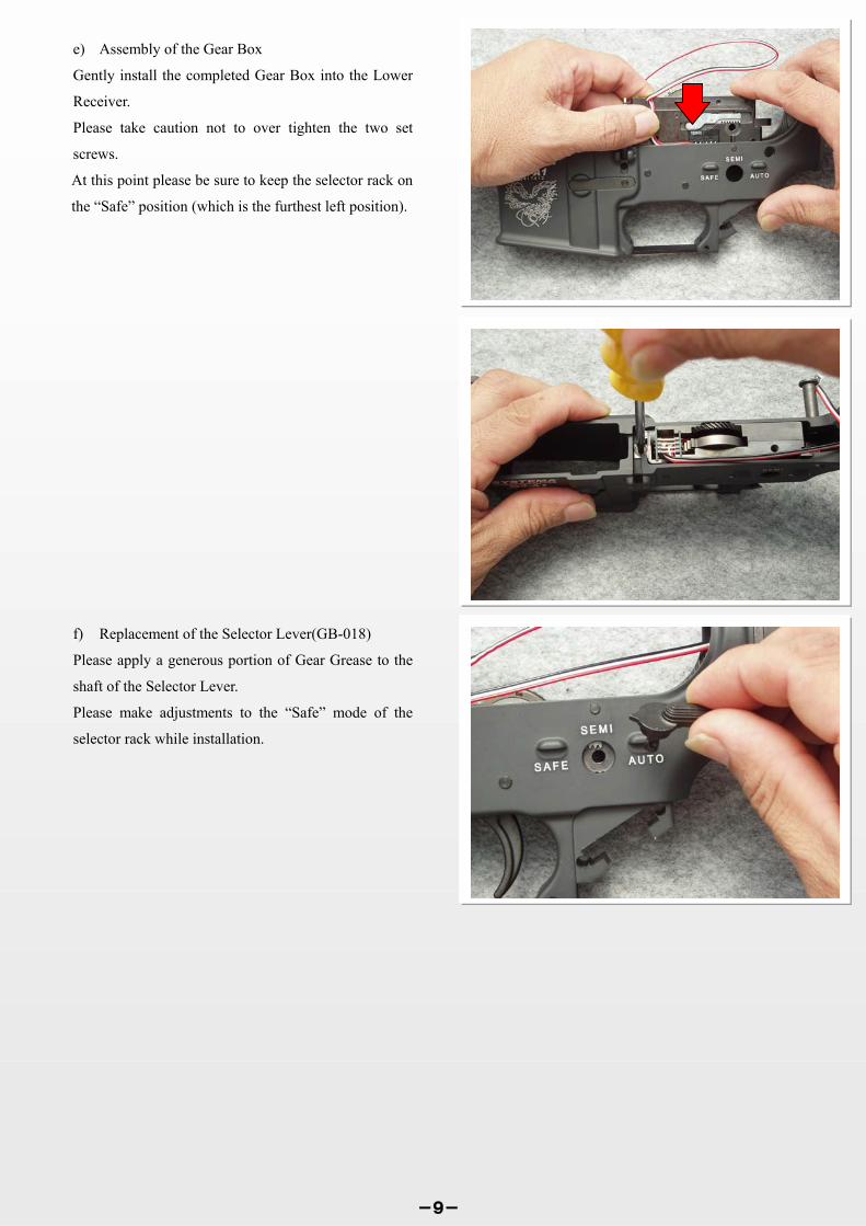
f) Replacement of the Selector Lever(GB-018)
Please apply a generous portion of Gear Grease to the
shaft of the Selector Lever.
Please make adjustments to the “Safe” mode of the
selector rack while installation.
e) Assembly of the Gear Box
Gently install the completed Gear Box into the Lower
Receiver.
Please take caution not to over tighten the two set
screws.
At this point please be sure to keep the selector rack on
the “Safe” position (which is the furthest left position).

1
④ Removal of the Motor Cord
Remove the solder from the motor cord.
③ Removal of the Motor Brush as well as the Motor
Brush Spring
While taking care not to injure yourself from the tension of
the spring, please remove the brush spring as well as the
brush.
② Removal of the Grip (LR-022)
You can pull the grip downward to remove.
It may be a bit tough, however while pulling on the grip
please take caution not to damage the cord.
6. Replacement of the Switch Device for the M4--A1
(EL-003-M4)Version
For the replacement of the Switch Device especially the
cord setup for the M4-A1 version, it will require a high
degree of skill.
Please proceed with great care.
① Removal of the Grip End (LR-024)
Unscrew the four-piece Grip End Screw(LR-027) to remove
the Grip End.
-10-

1
The Switch Device will be able to be removed at this point.
⑦ Removal of the Switch Device (EL-003-M4)
While taking care not to damage the cord, pass the cord
through the hole of the Stock Tube.
⑥ Loosen the Stock Tube Nut (SST-012)
To loosen the Stock Tube Nut please use the special wrench
as seen in the illustration.
Loosen the nut as much as possible without taking off.
Move the Stock Set Plate as far as the Stock Tube Nut has
been loosened.
⑤ Removal of the Stock Tube Cap (SST-015)
To remove the stock tube cap please use a 5mm pin punch
and pry using the hole.
In the event of disassembly for the future please apply a thin
layer of silicone grease on the O-Ring of the Stock Tube
Cap.
-11-

1
③ Removal of the Fixed Stock (FST-005) In the proceeding section(6-④), the Motor Cord has already
been removed therefore the Stock can be removed by
pulling the Stock from the Lower Receiver.
② Removal of the Stock Pipe End Screw (FST-019)As seen in this picture please use along PhillipsHead Screw Driver to loosen the Stock Pipe EndScrew.
7.Replacement of the Switch Device for the M16-A2 /
A3(EL-003-A2 / A3)Version.
This procedure is identical as replacement of the Switch
Device for the M4-A1 Version from 6- ① through ④
(removal of the motor cord).
The following details the removal of the Stock to access the
Motor Cord as well as the Switch Device.
① Removal of the Stock Pipe End Screw (FST-019)Remove the Stock Swivel Screw(FST-011).
Because the Butt Plate is only hooked onto the ButtPlate Assembly, no tools are required to remove.
-12-
④ Replacement of the Switch Device(EL-003-A2) In this illustration the Switch Device can beremoved from the Stock and replaced with theupgraded Switch Device from the Kit.

1
This is a zoomed in picture of the area to focus. Please take
caution to not spill extra solder onto any other location. We
recommend using a soldering iron with less than 30W of
power.
2) The area to focus on the Electronic Control Board is
located on the area to the furthest right of the board (as
seen on the illustration). Among the three jumper
locations the connector that says P1 is the area to which
you will need to apply solder.
Changes to the Firing Modes
By following the steps below to the S.E.C.U. you will be
able to change the function of the Semi/Full-Auto Mode to
Semi/3 Shot Burst.
1) Remove the S.E.C.U. from the Gear Box.
-13-
3) Once this procedure is completed this is what it should
look like. By removing the solder completely will return the
firing mode to Semi/Full-Auto.

1
② Pull out the Magazine Inner Case and remove the
Protector Plate.
2) Lubing the Protector Plate (MG-014)
Applying lubrication to the Protector Plate will ensure the
smooth movement of the Magazine Catch (MG-009 2-Piece
unit), thus improving the performance of feeding rounds.
① Remove the Magazine Outer Case Pin (MG-003 2-piece
unit) by tapping the pins with a 2mm pin punch. When
pushing the pins please be sure to push from the side that
has the magazine catch lip (as seen in the illustration).
Magazine Tune Up
By following the steps below, you will be able to maintain a
smooth feeding function of the magazine.
1) Repairing the Magazine Lip
During extensive use, the magazine lip may warp and the
lip area where the BB’s exit will tend to become narrow. In
the event that this happens, insert a pin punch with a
diameter of 6mm into the lip of the magazine well, gently
rock the pin punch forward and backwards as seen in the
illustration to make the necessary repairs. Never use
excessive force to pry open the lip.
-14-
③ Lubricate both sides of the Protector Plate (as seen in the
illustration). When lubricating please be sure to use
SYSTEMA Gear Grease.
Once completed, reverse the disassembly process to put
together the magazine.
SYSTEMA
2004 Model
M4-A1 2004 Model
M16-A2 2004 Model
M16-A3
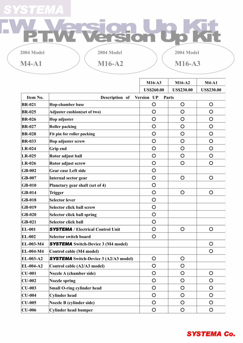
M16-A2 M4-A1 M16-A3
US$260.00 US$230.00 US$230.00
Item No. Description of Version UP Parts BR-021 Hop-chamber base ○ ○ ○
BR-025 Adjuster cushion(set of two) ○ ○ ○
BR-026 Hop adjuster ○ ○ ○
BR-027 Roller packing ○ ○ ○
BR-028 Fit pin for roller packing ○ ○ ○
BR-033 Hop adjuster screw ○ ○ ○
LR-024 Grip end ○ ○ ○
LR-025 Rotor adjust ball ○ ○ ○
LR-026 Rotor adjust screw ○ ○ ○
GB-002 Gear case Left side ○ GB-007 Internal sector gear ○ ○ ○
GB-010 Planetary gear shaft (set of 4) ○
GB-014 Trigger ○ ○ ○
GB-018 Selector lever ○ GB-019 Selector click ball screw ○ GB-020 Selector click ball spring ○ GB-021 Selector click ball ○ EL-001 SYSTEMA / Electrical Control Unit ○ ○ ○
EL-002 Selector switch board ○ EL-003-M4 SYSTEMA Switch-Device 3 (M4 model) ○
EL-004-M4 Control cable (M4 model) ○
EL-003-A2 SYSTEMA Switch-Device 3 (A2/A3 model) ○ ○ EL-004-A2 Control cable (A2/A3 model) ○ ○ CU-001 Nozzle A (chamber side) ○ ○ ○
CU-002 Nozzle spring ○ ○ ○
CU-003 Small O-ring cylinder head ○ ○ ○
CU-004 Cylinder head ○ ○ ○
CU-005 Nozzle B (cylinder side) ○ ○ ○
CU-006 Cylinder head bumper ○ ○ ○
SYSTEMA Co.