table of contents · ac1 j1 ac2 j2 j3 lcd. view of the display screentype: 2lineswith16characters....
TRANSCRIPT
TABLE OF CONTENTS
1 Precautions and introduction.………………….……………………………… 1.1
2 Connecting the module.…..………………….…………………………………2.1
3 Getting started and operating the system……………………………………..3.1
4 Operating principles..…………………………………………………………….4.1
5 Advanced tests…..………………………………………………………………..5.1
6 Valves, diodes, regulators and cathodic indicators.………………………..…6.1
7 Technical characteristics…………………………………………………………7.1
8 Problems and solutions.…………………………………………………………..8.1
Duokit_user guide
1 PRECAUTIONS AND INTRODUCTION
Dangerous voltages are present at all points of the module and on the peripheral elements. Do not touchany of the connections while power is on, and wait for at least one minute after switching off the power inorder to allow the condensers to discharge.
Likewise, ensure that you have the necessary competence to assemble and use this item. Otherwise, askfor the help of an experienced person.
During the first test, make sure that the module is placed on an insulated surface and that no object orconducting particle is on this surface.
The module functions on an impulse mode. This mode is caried out by a fast microprocomputer whichcontrols all the functions, and allows high plate current measurement (340 mA) while minimizing thevolume, weight, consumption and cost.
This type of operation prevents all kinds of overdissipation, and insure perfect security for the tube. Testscan also be undertaken without risk even with parameters over specification limits.
The embedded supply for the plate, screen and grid 1 allows testing of most audio tubes as well as of asignificant majority of radio tubes, cathodic indicators, regulators, diodes, rectifiers, and valves.
A supply module, proposed as a complementary accessory, enables the delivery of 3 heating voltages : 4V,5V, 6.3V / 3 A minimum current.
The heating circuit is floating. Thus, direct heating tubes can also be measured.
Grid 1 voltage (bias) setting is done in a flexible and precise manner by a 10-turn potentiometer withdecimal display in real time.
Because of the small power required, the module can be powered by a simple 12V battery (requiredcurrent of approximately 2A), or by a cigarette lighter of a car - through a small 12V to 220V converter,available as a complementary accessory.
In this way, measurements can be done quickly and wherever you are : in a flea market, garage sale, exhibit,etc. This is useful for expensive tubes or when buying many tubes.
All circuitry is protected against overload as well as against connection errors. That said, however, an errorin connection could damage a tube, so care is highly recommended.
Duokit_user guide 1.1
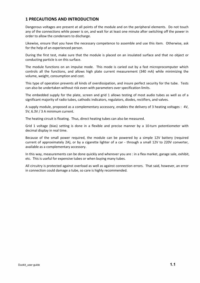
2 CONNECTING THE MODULE
View of the PCB and the connectors
= Pin 1
Duokit_user guide 2.1
AC3
J5
AC1 J1 AC2 J2
J3
LCD
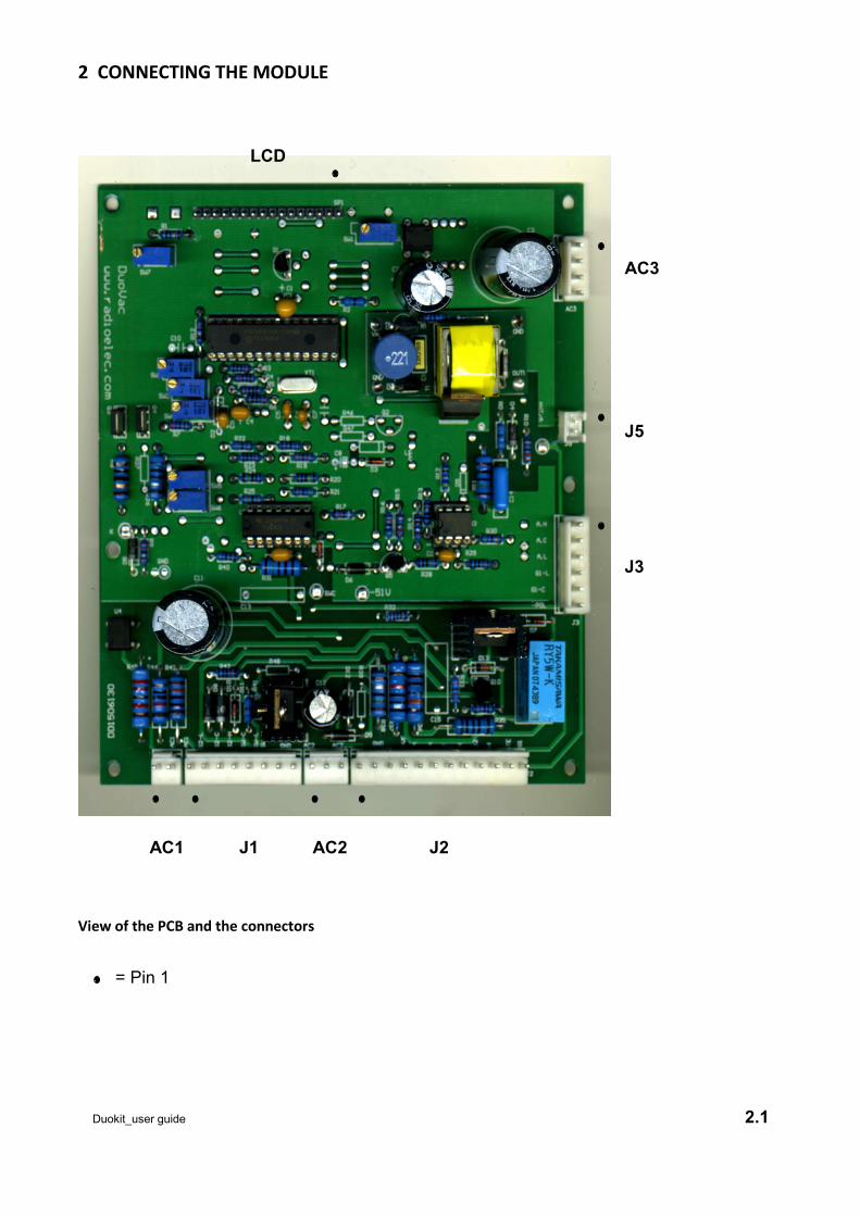
View of the display
Screen type : 2 lines with 16 characters.
Blue, with backlight
Dimensions: 70 x 25 mm
Driver: HD44780
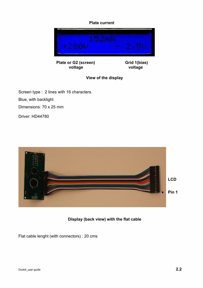
Display (back view) with the flat cable
Flat cable lenght (with connectors) : 20 cms
Duokit_user guide 2.2
Pin 1
LCD
Plate or G2 (screen)voltage
Grid 1(bias)voltage
Plate current
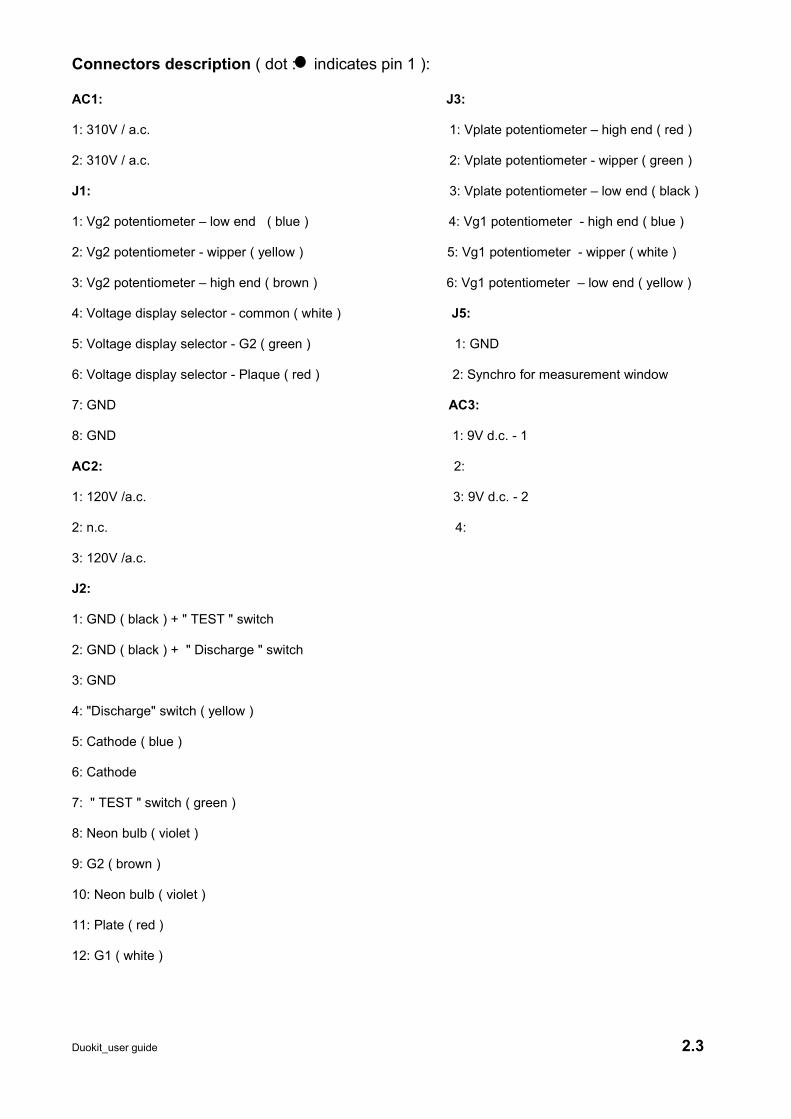
Connectors description ( dot : indicates pin 1 ):
AC1: J3:
1: 310V / a.c. 1: Vplate potentiometer – high end ( red )
2: 310V / a.c. 2: Vplate potentiometer - wipper ( green )
J1: 3: Vplate potentiometer – low end ( black )
1: Vg2 potentiometer – low end ( blue ) 4: Vg1 potentiometer - high end ( blue )
2: Vg2 potentiometer - wipper ( yellow ) 5: Vg1 potentiometer - wipper ( white )
3: Vg2 potentiometer – high end ( brown ) 6: Vg1 potentiometer – low end ( yellow )
4: Voltage display selector - common ( white ) J5:
5: Voltage display selector - G2 ( green ) 1: GND
6: Voltage display selector - Plaque ( red ) 2: Synchro for measurement window
7: GND AC3:
8: GND 1: 9V d.c. - 1
AC2: 2:
1: 120V /a.c. 3: 9V d.c. - 2
2: n.c. 4:
3: 120V /a.c.
J2:
1: GND ( black ) + " TEST " switch
2: GND ( black ) + " Discharge " switch
3: GND
4: "Discharge" switch ( yellow )
5: Cathode ( blue )
6: Cathode
7: " TEST " switch ( green )
8: Neon bulb ( violet )
9: G2 ( brown )
10: Neon bulb ( violet )
11: Plate ( red )
12: G1 ( white )
Duokit_user guide 2.3

Connections & supplies
T1: 120 V + 310 V transfo./ 110 V primary( red / yellow ) - 230 V ( red / green )
T2: AC / DC regulated supply 9V d.c. / Primary 85 V - 260 V ( AC inputs)
3 ferrite beads and 3 knobs are not shown but will be delivered with the kit.
Duokit_user guide 2.4
AC3
J3
AC1
AC2
J2
G1
Plate
G2
Cathode
Vg2 pot.Vp / Vg2Display sel.
TEST
Discharge
Vg1 pot.
Vplate pot.T1
Neon
T2
J1
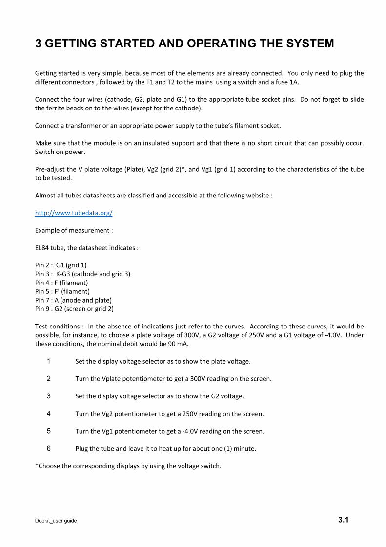
3 GETTING STARTED AND OPERATING THE SYSTEM
Getting started is very simple, because most of the elements are already connected. You only need to plug thedifferent connectors , followed by the T1 and T2 to the mains using a switch and a fuse 1A.
Connect the four wires (cathode, G2, plate and G1) to the appropriate tube socket pins. Do not forget to slidethe ferrite beads on to the wires (except for the cathode).
Connect a transformer or an appropriate power supply to the tube’s filament socket.
Make sure that the module is on an insulated support and that there is no short circuit that can possibly occur.Switch on power.
Pre-adjust the V plate voltage (Plate), Vg2 (grid 2)*, and Vg1 (grid 1) according to the characteristics of the tubeto be tested.
Almost all tubes datasheets are classified and accessible at the following website :
http://www.tubedata.org/
Example of measurement :
EL84 tube, the datasheet indicates :
Pin 2 : G1 (grid 1)Pin 3 : K-G3 (cathode and grid 3)Pin 4 : F (filament)Pin 5 : F’ (filament)Pin 7 : A (anode and plate)Pin 9 : G2 (screen or grid 2)
Test conditions : In the absence of indications just refer to the curves. According to these curves, it would bepossible, for instance, to choose a plate voltage of 300V, a G2 voltage of 250V and a G1 voltage of -4.0V. Underthese conditions, the nominal debit would be 90 mA.
1 Set the display voltage selector as to show the plate voltage.
2 Turn the Vplate potentiometer to get a 300V reading on the screen.
3 Set the display voltage selector as to show the G2 voltage.
4 Turn the Vg2 potentiometer to get a 250V reading on the screen.
5 Turn the Vg1 potentiometer to get a -4.0V reading on the screen.
6 Plug the tube and leave it to heat up for about one (1) minute.
*Choose the corresponding displays by using the voltage switch.
Duokit_user guide 3.1
Check that the neon indicator is turned off or is blinking. For certain tubes, this light could be turned oncontinuously without blinking even if there is no short circuit. In general , this kind of phenomenon is created bytubes which have high transconductance or power or by valves and cathodic indicators.
It is not dangerous to carry out tests even if the light is turned on.
Push on the « TEST » button and read the value of the plate current in mA.
Release the button. The test is completed.
More measurements : transconductance , internal resistance and gain are possible and simple.
These measurements/tests are described on§ 6.
Tubes matching is done by a simple method. Test several tubes of the same type without changing theadjustments in order to pair up (or in quartets) tubes with plate currents whose measurements are closest.
For double tubes like : ecc81, ecc82, ecc83, ecc88 – 6sl7, 6sn7, etc…The measurement of any of the internaltriodes can be undertaken by swaping the connection to either the plateof triode 1 or triode 2 ( all other sameelectrodes connected together ). This can be easily undertaken with a simple inverter.
More comprehensive measurements are described in §5.
The testing of valves, diodes , cathodic indicators, gas regulators is possible and described on §6.
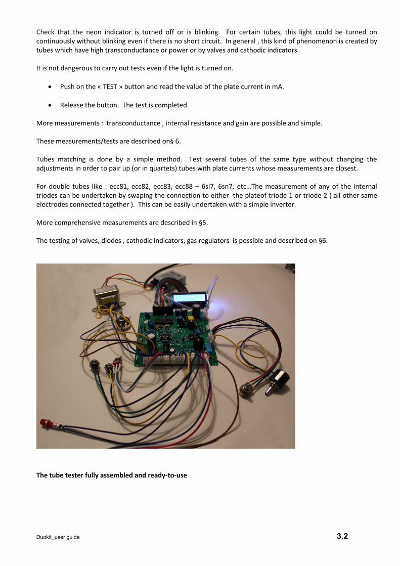
The tube tester fully assembled and ready-to-use
Duokit_user guide 3.2
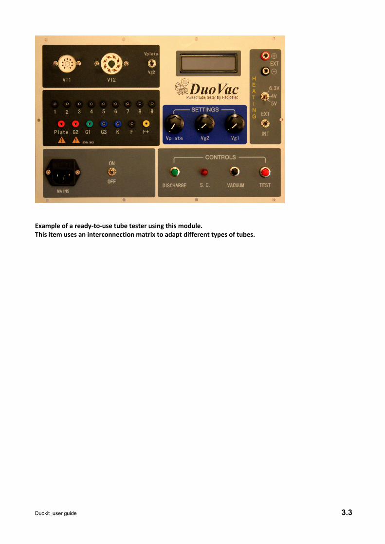
Example of a ready-to-use tube tester using this module.This item uses an interconnection matrix to adapt different types of tubes.
Duokit_user guide 3.3
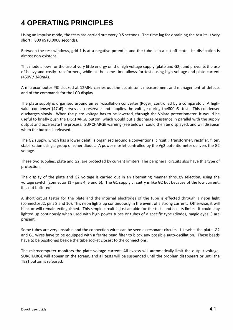
4 OPERATING PRINCIPLESUsing an impulse mode, the tests are carried out every 0.5 seconds. The time lag for obtaining the results is veryshort : 800 uS (0.0008 seconds).
Between the test windows, grid 1 is at a negative potential and the tube is in a cut-off state. Its dissipation isalmost non-existent.
This mode allows for the use of very little energy on the high voltage supply (plate and G2), and prevents the useof heavy and costly transformers, while at the same time allows for tests using high voltage and plate current(450V / 340mA).
A microcomputer PIC clocked at 12MHz carries out the acquisiton , measurement and management of defectsand of the commands for the LCD display.
The plate supply is organised around an self-oscillation converter (Royer) controlled by a comparator. A high-value condenser (47µF) serves as a reservoir and supplies the voltage during the800µS test. This condenserdischarges slowly. When the plate voltage has to be lowered, through the Vplate potentiometer, it would beuseful to briefly push the DISCHARGE button, which would put a discharge resistance in parallel with the supplyoutput and accelerate the process. SURCHARGE warning (see below) could then be displayed, and will disapearwhen the button is released.
The G2 supply, which has a lower debit, is organized around a conventional circuit : transformer, rectifier, filter,stabilization using a group of zener diodes. A power mosfet controlled by the Vg2 potentiometer delivers the G2voltage.
These two supplies, plate and G2, are protected by current limiters. The peripheral circuits also have this type ofprotection.
The display of the plate and G2 voltage is carried out in an alternating manner through selection, using thevoltage switch (connector J1 - pins 4, 5 and 6). The G1 supply circuitry is like G2 but because of the low current,it is not buffered.
A short circuit tester for the plate and the internal electrodes of the tube is effected through a neon light(connector J2, pins 8 and 10). This neon lights up continuously in the event of a strong current. Otherwise, it willblink or will remain extinguished. This simple circuit is just an aide for the tests and has its limits. It could staylighted up continously when used with high power tubes or tubes of a specific type (diodes, magic eyes…) arepresent.
Some tubes are very unstable and the connection wires can be seen as resonant circuits. Likewise, the plate, G2and G1 wires have to be equipped with a ferrite bead filter to block any possible auto-oscillation. These beadshave to be positioned beside the tube socket closest to the connections.
The microcomputer monitors the plate voltage current. All excess will automatically limit the output voltage,SURCHARGE will appear on the screen, and all tests will be suspended until the problem disappears or until theTEST button is released.
Duokit_user guide 4.1
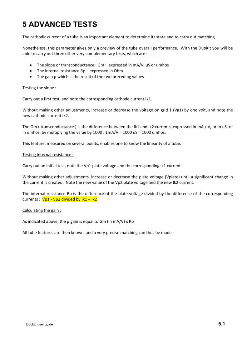
5 ADVANCED TESTSThe cathodic current of a tube is an important element to determine its state and to carry out matching.
Nonetheless, this parameter gives only a preview of the tube overall performance. With the DuoKit you will beable to carry out three other very complementary tests, which are :
The slope or transconductance : Gm : expressed in mA/V, uS or umhos The internal resistance Rp : expressed in Ohm The gain µ which is the result of the two preceding values
Testing the slope :
Carry out a first test, and note the corresponding cathode current Ik1.
Without making other adjustments, increase or decrease the voltage on grid 1 (Vg1) by one volt, and note thenew cathode current Ik2.
The Gm ( transconductance ) is the difference between the lk1 and lk2 currents, expressed in mA / V, or in uS, orin umhos, by multiplying the value by 1000 : 1mA/V = 1000 uS = 1000 umhos.
This feature, measured on several points, enables one to know the linearity of a tube.
Testing internal resistance :
Carry out an initial test, note the Vp1 plate voltage and the corresponding lk1 current.
Without making other adjustments, increase or decrease the plate voltage (Vplate) until a significant change inthe current is created. Note the new value of the Vp2 plate voltage and the new lk2 current.
The internal resistance Rp is the difference of the plate voltage divided by the difference of the correspondingcurrents : Vp1 - Vp2 divided by Ik1 – Ik2
Calculating the gain :
As indicated above, the µ gain is equal to Gm (in mA/V) x Rp
All tube features are then known, and a very precise matching can thus be made.
Duokit_user guide 5.1
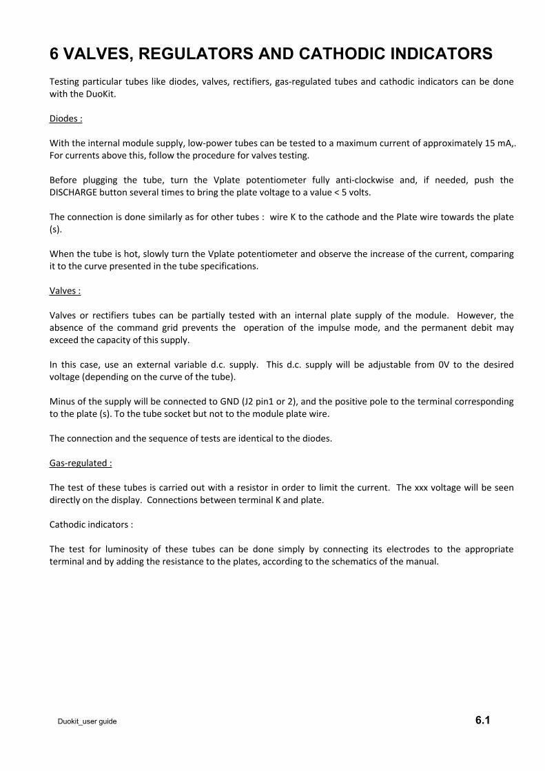
6 VALVES, REGULATORS AND CATHODIC INDICATORSTesting particular tubes like diodes, valves, rectifiers, gas-regulated tubes and cathodic indicators can be donewith the DuoKit.
Diodes :
With the internal module supply, low-power tubes can be tested to a maximum current of approximately 15 mA,.For currents above this, follow the procedure for valves testing.
Before plugging the tube, turn the Vplate potentiometer fully anti-clockwise and, if needed, push theDISCHARGE button several times to bring the plate voltage to a value < 5 volts.
The connection is done similarly as for other tubes : wire K to the cathode and the Plate wire towards the plate(s).
When the tube is hot, slowly turn the Vplate potentiometer and observe the increase of the current, comparingit to the curve presented in the tube specifications.
Valves :
Valves or rectifiers tubes can be partially tested with an internal plate supply of the module. However, theabsence of the command grid prevents the operation of the impulse mode, and the permanent debit mayexceed the capacity of this supply.
In this case, use an external variable d.c. supply. This d.c. supply will be adjustable from 0V to the desiredvoltage (depending on the curve of the tube).
Minus of the supply will be connected to GND (J2 pin1 or 2), and the positive pole to the terminal correspondingto the plate (s). To the tube socket but not to the module plate wire.
The connection and the sequence of tests are identical to the diodes.
Gas-regulated :
The test of these tubes is carried out with a resistor in order to limit the current. The xxx voltage will be seendirectly on the display. Connections between terminal K and plate.
Cathodic indicators :
The test for luminosity of these tubes can be done simply by connecting its electrodes to the appropriateterminal and by adding the resistance to the plates, according to the schematics of the manual.
Duokit_user guide 6.1
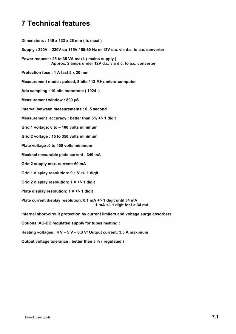
7 Technical features
Dimensions : 146 x 133 x 28 mm ( h. maxi )
Supply : 220V – 230V ou 115V / 50-60 Hz or 12V d.c. via d.c. to a.c. converter
Power request : 25 to 35 VA maxi. ( mains supply )Approx. 2 amps under 12V d.c. via d.c. to a.c. converter
Protection fuse : 1 A fast 5 x 20 mm
Measurement mode : pulsed, 8 bits / 12 MHz micro-computer
Adc sampling : 10 bits monotone ( 1024 )
Measurement window : 800 µS
Interval between measurements : 0, 5 second
Measurement accuracy : better than 5% +/- 1 digit
Grid 1 voltage: 0 to – 100 volts minimum
Grid 2 voltage : 15 to 350 volts minimum
Plate voltage :0 to 450 volts minimum
Maximal mesurable plate current : 340 mA
Grid 2 supply max. current: 60 mA
Grid 1 display resolution: 0,1 V +/- 1 digit
Grid 2 display resolution: 1 V +/- 1 digit
Plate display resolution: 1 V +/- 1 digit
Plate current display resolution: 0,1 mA +/- 1 digit until 34 mA1 mA +/- 1 digit for I > 34 mA
Internal short-circuit protection by current limiters and voltage surge absorbers
Optional AC-DC regulated supply for tubes heating :
Heating voltages : 4 V – 5 V – 6,3 V/ Output current: 3,5 A maximum
Output voltage tolerance : better than 5 % ( regulated )
Duokit_user guide 7.1
8 PROBLEMS AND SOLUTIONS1. The tester does not switch on :
Check the connection to the power supply and the fuse 1A.
If the tester works on battery through a converter, check the battery and the converter.
2. No measurements :
Check settings, tube heating and push only the « TEST » button, then try another tube.
3. The tube does not heat up or the results seem wrong :
Using an ohmeter, check that the tube filament is not cut and that the heating voltage is applied and iscorrect.
Then check the connections of the tube to the module wires.
Check the values of the test voltage Vg1, Vg2 and V plate.
4. The display indicates « SURCHARGE » :
Release the « TEST » button as well as the « DISCHARGE » button.
5. Upon pushing the « TEST » button, the values on the display change quickly and quite significantly :
The most probable cause is that the tube is oscillating during the test. This phenomenon is rare but canhappen for tubes with significant slopes. Ensure that the ferrite beads are present and close to the tubeunder test.
Reduce the Vg1 voltage (more negative, turn Vg1 potentiometer anti-clockwise), then slowly turn thepotentiometer Vg1 clockwise while maintaining the « TEST » button pressed.
6. The display values are abnormal or truncated :
Turn off power, and after around 10 seconds, turn on power again.
Duokit_user guide 8.1