table of contents - igvc. · pdf filethe arc got inspiration from explosive ordinance disposal...
TRANSCRIPT
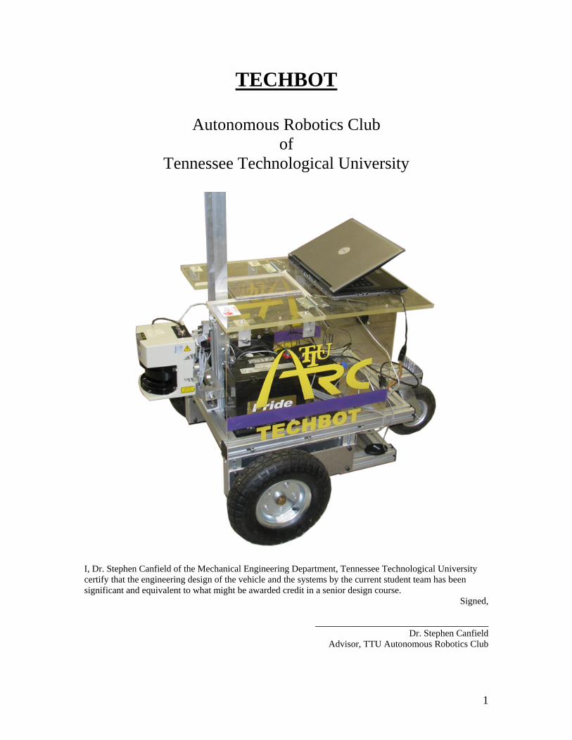
TECHBOT
Autonomous Robotics Club of
Tennessee Technological University
I, Dr. Stephen Canfield of the Mechanical Engineering Department, Tennessee Technological University certify that the engineering design of the vehicle and the systems by the current student team has been significant and equivalent to what might be awarded credit in a senior design course.
Signed,
_____________________________________ Dr. Stephen Canfield
Advisor, TTU Autonomous Robotics Club
1

TABLE OF CONTENTS
SECTION 1: INTRODUCTION................................................................................................................. 3 1.1 ARC TECHBOT INSPIRATION ............................................................................................................. 3
SECTION 2: TEAM STRUCTURE ........................................................................................................... 3 SECTION 3: DESIGN PROCESS ............................................................................................................. 4 SECTION 4: TECHBOT MECHANICAL................................................................................................ 6
4.1 CHASSIS................................................................................................................................................ 6 4.2 DRIVETRAIN ......................................................................................................................................... 6
SECTION 5: TECHBOT SENSORS.......................................................................................................... 6 5.1 SICK RANGER...................................................................................................................................... 6 5.2 CAMERA ............................................................................................................................................... 7 5.3 GPS ...................................................................................................................................................... 7 5.4 WHEEL ENCODERS ............................................................................................................................... 7 5.5 DIGITAL COMPASS................................................................................................................................ 7
SECTION 6: TECHBOT LOW-LEVEL SYSTEMS ................................................................................ 8 6.1 ELECTRONICS DEVELOPMENT .............................................................................................................. 8 6.2 LOW-LEVEL LOGIC PCB (SERVO LOOP).............................................................................................. 8 6.3 VELOCITY CONTROL............................................................................................................................. 9 6.4 POWER DISTRIBUTION ........................................................................................................................ 10 6.5 EMERGENCY STOP .............................................................................................................................. 11
SECTION 7: TECHBOT HIGH-LEVEL NAVIGATION ..................................................................... 11 7.1 MAPPING ............................................................................................................................................ 12 7.2 VISION ................................................................................................................................................ 13 7.3 PATH PLANNING & DECISION MAKING .............................................................................................. 13
SECTION 8: PERFORMANCE CHARACTERISTICS........................................................................ 15 SECTION 9: COST.................................................................................................................................... 15 SECTION 10: CONCLUSION.................................................................................................................. 16
2

Section 1: Introduction
The Autonomous Robotics Club of Tennessee Technological University is proud
to present: TECHBOT. TECHBOT is the first robot ever created by TTU ARC, and is its
first entry ever into a robotics competition. TECHBOT was built from scratch based on
the combined vision of ARC members and is designed to be modular and easy to
transplant onto a wide variety of autonomous navigation robot chassis. The algorithms
have been specifically tweaked to complete the challenges proposed by the Intelligent
Ground Vehicle Competition of 2008, but were designed with broader portability options
in mind.
1.1 ARC TECHBOT Inspiration
The ARC got inspiration from Explosive Ordinance Disposal (EOD) robots.
These robots are invaluable to military and police operations, and provide a unique niche
for automation in an already existing robotics market. TECHBOT’s design makes it
ideally portable to an already-existing EOD chassis with a little re-configuring to the low-
level controls to match the chassis’ structure.
Section 2: Team Structure
The ARC initially divided itself into four sub-teams for organization and
efficiency: Mechanical, High-Level Navigation, Sensors, and Low-Level Systems. Each
ARC member is listed below, along with his educational background, primary sub-team
choice, and estimated hours of work.
NAME EDUCATION LEVEL SUB-TEAM HOURS
Hunter McClelland Mechanical Engr. Undergraduate Sensors 450
Nick Patton Mechanical Engr. Undergraduate High-Level 200
Marbin Pazos-Revilla Electrical Engr. Graduate Low-Level 180
Jeremy Langston Electrical Engr. Graduate Low-Level 80
John Adcox Mechanical Engr. Undergraduate Mechanical 120
Jason Taylor Electrical Engr. Undergraduate Low-Level 100
3

Ben Eckart Computer Sci. Undergraduate High-Level 220
Timmy Smith Mechanical Engr. Undergraduate Mechanical 120
Gerrit Coetzee Mechanical Engr. Undergraduate High-Level 50
Matt Parrish Mechanical Engr. Undergraduate Mechanical 40
Brett Steigerwaldt Mechanical Engr. Undergraduate Mechanical 28
Jimmy Warren Electrical Engr. Undergraduate Sensors 30
Tristan Hill Mechanical Engr. Undergraduate Sensors 48
Section 3: Design Process
The division of ARC into sub-teams facilitated a interrelated multi-branched
design process for TECHBOT. The sub-teams functioned as independent but coordinated
entities, so problems were generally worked on by an individual team. The design
process followed by each team for each task is as follows:
4

Define Task Goals / Criteria for Success
Propose Solutions (Brainstorm)
Gather Materials / Knowledge / Personnel
Communicate with Other Sub-teams
Take a Small Step Towards Completion
Test Step / Analyze Partial Results
Integrate Solution into System
Test System / Record Improvement Areas
Task Fully Complete? Task Fully Complete? NoYes
Identify the Design Opportunity
It is important to note that the design process never actually finishes. ARC
recognizes that no solution is flawless and therefore decided to implement a “perpetual-
improvement” design paradigm. Not only is completing each task an iterative process,
but integrating each solution into the total system is also iterative, in the sense that every
individual, interdependent solution opens new opportunities for improvement to the
entire system.
5

Section 4: TECHBOT Mechanical
Many of EOD robots have a skid-steering system. However, due to the
challenges of autonomizing a skid-steer robot, thus forcing unknown wheel slippage, a
differential steer chassis was chosen and fabricated from scratch as a base system.
4.1 Chassis
As explained above, the chassis that is being used has a 2-wheel differential
steering system with a single caster wheel for support. The advantages of the system are
that there is almost no wheel slippage, the drivetrain is relatively simple, the
maneuverability is very good, and the turning radius can be theoretically zero.
4.2 Drivetrain
The vehicle drivetrain that was chosen uses a Servo Systems DC Maxon
servomotor for each wheel. Each servomotor has a small spur gear attached to its output
shaft and has a chain running across it to a gear that is directly attached to the wheel
shaft. This system allows for a large variety of gear ratios to maximize the performance
of the motors, and a gear ratio of 4:1 was selected. Another key advantage of a choosing
a chain drive is that it allows the fore-to-aft position of the motors to be different on each
side. Offsetting the motors reduces the necessary track width of the chassis.
Section 5: TECHBOT Sensors
The sensor suite consists of a laser rangefinder, a camera, wheel encoders, GPS,
and a compass. All of these sensors, except the wheel encoders, are connected to a laptop
computer, which does the “high-level thinking” (See Section 7). The wheel encoders are
connected to an embedded microcontroller which does the “low-level” transforms (See
Section 6). Each of the sensors’ drivers has been custom modified or re-designed for
TECHBOT’s particular needs.
5.1 SICK Ranger
The first major sensor is the SICK LMS-291 Laser Ranger
Finder (Fig 5.1). The main function of this sensor is physical
obstacle detection. TECHBOT’s SICK Ranger has a maximum
6 Figure 5.1
distance of 32 meters with a resolution of 10 millimeters. The rangefinder takes 181
length measurements at 1° increments per sweep. The high-level navigation software
converts these measurements and plots them on the map as obstacles.
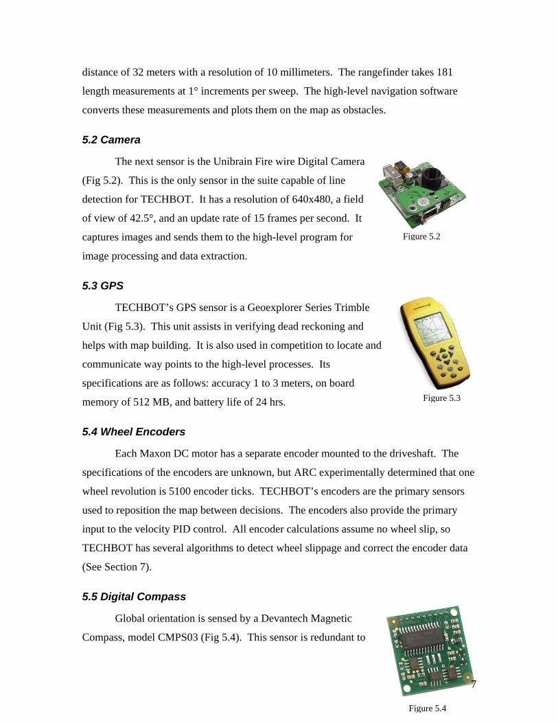
5.2 Camera
The next sensor is the Unibrain Fire wire Digital Camera
(Fig 5.2). This is the only sensor in the suite capable of line
detection for TECHBOT. It has a resolution of 640x480, a field
of view of 42.5°, and an update rate of 15 frames per second. It
captures images and sends them to the high-level program for
image processing and data extraction.
Figure 5.2
5.3 GPS
Figure 5.3
TECHBOT’s GPS sensor is a Geoexplorer Series Trimble
Unit (Fig 5.3). This unit assists in verifying dead reckoning and
helps with map building. It is also used in competition to locate and
communicate way points to the high-level processes. Its
specifications are as follows: accuracy 1 to 3 meters, on board
memory of 512 MB, and battery life of 24 hrs.
5.4 Wheel Encoders
Each Maxon DC motor has a separate encoder mounted to the driveshaft. The
specifications of the encoders are unknown, but ARC experimentally determined that one
wheel revolution is 5100 encoder ticks. TECHBOT’s encoders are the primary sensors
used to reposition the map between decisions. The encoders also provide the primary
input to the velocity PID control. All encoder calculations assume no wheel slip, so
TECHBOT has several algorithms to detect wheel slippage and correct the encoder data
(See Section 7).
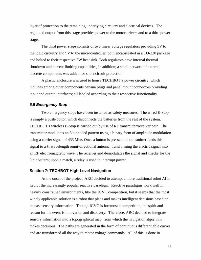
5.5 Digital Compass
Figure 5.4
Global orientation is sensed by a Devantech Magnetic
Compass, model CMPS03 (Fig 5.4). This sensor is redundant to
7

the calculations from the wheel encoders, and therefore provides a check on their
accuracy. Its resolution is 0.1°, but its accuracy is affected significantly by tilting away
from the horizontal.
Section 6: TECHBOT Low-Level Systems
During the initial design phase, ARC made the choice to build its own motor and
low-level controllers from an HCS12 microcontroller along with IC's (integrated circuits)
for driving the motors and capturing encoder counts. Through the use of real-time
interrupts on the HCS12, effective real-time control is possible. The Mini-Dragon HCS12
board has two serial lines and many I/O pins through which interfacing with sensors and
other hardware is conducted. ARC built the entire system from the ground up, including
making custom printed circuit boards and developing code. This do-it-yourself approach
gives a much more versatile product than an off-the-shelf solution, it drastically reduces
cost for the components, and it builds a knowledge foundation that ARC, being a rookie
team, has not yet acquired.
6.1 Electronics Development
The goal of the electronics system is to supply appropriate power to all necessary
components and to provide servo loops on the DC motors. This system involves
numerous subcomponents in order to compartmentalize the design for increased
modularity and subsequent benefits from layer abstraction. Once a subsystem is
complete and thoroughly tested, it can be effectively ignored. Modularity allows for
parallelism in design, therefore multiple team members may work on different
subsystems individually without fear of conflict. Subsystems, such as the servo loop,
began with a simple engineering design. Due to the iterative nature of design processes,
the design underwent changes – some more significant than others. Development
included SPICE simulations, logical layout, breadboarding, prototyping, PCB (printed
circuit board) layout, PCB etching, and, ultimately, PCB milling and assembly.
6.2 Low-Level Logic PCB (Servo Loop)
To provide for a higher degree of position reckoning, the robot drive system uses
a closed loop servo circuit. Each DC motor is equipped with a 1,000 count encoder,
8

which is increased to 5,100 due to the shaft's gearbox. This information is fed back into
the microcontroller using a special logic PCB. In this PCB is an Agilent 2032 Quadrature
Decoder. This IC takes two encoder inputs and counts up and down the number of ticks
the encoder sees. This information is stored internally in a 32 bit register which is
accessible by the use of several command signals and 8 data lines. To decrease the
complexity of the microcontroller software, a simple gather-reset routine is implemented
which retrieves the bits 15 to 8 of the 2032 IC and then resets the count back to zero. The
relatively high speed of the microcontroller allows for minimal error due to lost counts.
The information gathered on encoder counts is then used in the microcontroller's PID
control algorithm. PID control, which is explained in the following section, attempts to
supply drive signals such that the robot’s accelerations and speeds are maintained stably
and controllably. These drive signals are sent as pulse-width modulated signals to the
motor drivers. To allow for maximum resiliency, industrial drivers were used in lieu of
simple H-Bridges such as the L293's and 33886's. The drivers are fed 24V DC from the
power distribution circuitry to induce the field inside the DC motors.
6.3 Velocity Control
For the low-level motor controller, a proportional–integral–derivative (PID)
closed-loop control system was coded on the Mini-Dragon HCS12 microcontroller. A
representative diagram of the loop is shown in Figure 6.1. Velocity is controlled by
creating “setpoints” in terms of encoder ticks per interrupt, dictated via serial connection
by the high-level control on the laptop. The PID system turns the setpoints into PWM
outputs which are sent directly to the motors. The entire system is simple yet robust, with
the control loop running at 1024 Hertz. The serial communication between the laptop and
the microcontroller is bidirectional; the laptop sends motor speeds and receives encoder
data for dead reckoning during map building.
.
9

Figure 6.1
6.4 Power Distribution
TECHBOT is powered via two 12V 55A/h lead-acid batteries connected in series;
providing a first stage 24V power source from which all the remaining power stages are
derived. A 20V DC relay and switch provide the electrical interface between the first and
second power stage.
The second power stage consists of two high current linear voltage regulators;
each encapsulated in TO-3 package and bolted to a 12W heat sink. These regulators have
negligible voltage drop and can withstand peak and steady currents of 12 and 8 amps
respectively. In addition, their built-in current and thermal sensing capabilities provide a
10
layer of protection to the remaining underlying circuitry and electrical devices. The
regulated output from this stage provides power to the motor drivers and to a third power
stage.
The third power stage consists of two linear voltage regulators providing 5V to
the logic circuitry and 9V to the microcontroller, both encapsulated in a TO-220 package
and bolted to their respective 5W heat sink. Both regulators have internal thermal
shutdown and current limiting capabilities, in addition; a small network of external
discrete components was added for short-circuit protection.
A plastic enclosure was used to house TECHBOT’s power circuitry, which
includes among other components banana plugs and panel mount connectors providing
input and output interfaces; all labeled according to their respective functionality.
6.5 Emergency Stop
Two emergency stops have been installed as safety measures. The wired E-Stop
is simply a push-button which disconnects the batteries from the rest of the system.
TECHBOT's wireless E-Stop is carried out by use of RF transmitter/receiver pair. The
transmitter modulates an 8 bit coded pattern using a binary form of amplitude modulation
using a carrier signal of 433 Mhz. Once a button is pressed the transmitter feeds this
signal to a ¼ wavelength omni-directional antenna, transforming the electric signal into
an RF electromagnetic wave. The receiver end demodulates the signal and checks for the
8 bit pattern; upon a match, a relay is used to interrupt power.
Section 7: TECHBOT High-Level Navigation
At the onset of the project, ARC decided to attempt a more traditional robot AI in
lieu of the increasingly popular reactive paradigm. Reactive paradigms work well in
heavily constrained environments, like the IGVC competition, but it seems that the most
widely applicable solution is a robot that plans and makes intelligent decisions based on
its past sensory information. Though IGVC is foremost a competition, the spirit and
reason for the event is innovation and discovery. Therefore, ARC decided to integrate
sensory information into a topographical map, from which the navigation algorithm
makes decisions. The paths are generated in the form of continuous differentiable curves,
and are transformed all the way to motor voltage commands. All of this is done in
11

original Python or C code. Ultimately, although a deliberative-hybrid robot is more
difficult than a reactive one, TECHBOT truly aspires to the “I” in IGVC.
7.1 Mapping
TECHBOT visualizes the world through its primary unit of sensory information,
the “blip.” Blips asynchronously accrue from the detection sensors by the use of
multithreading in the Python high-level controller. The navigation algorithm, however,
does not need to be evaluated for every blip, because a multi-tiered control scheme with
different asynchronous sensor and computational rates runs as outlined below:
System Data Rate (Hertz)
Navigation / Path Planning / Map Building 2
GPS 2
Camera 15
Sick LMS291 75
PID Control Loop 1024
Table 7.1
The blips accumulate as a list of discrete coordinates coupled with metadata, including a
timestamp and various types information. Through the use of Python's object-oriented
language features, the blip object is generic enough that it can be used to represent lines,
obstacles, or any other desired object on the map. Thus, all sensory information can be
overlaid on the same map in a unified fashion.
The tiered control scheme assembles a map only when necessary in order to
conserve computation; thus, a map is created only when the navigation algorithm asks for
it. The system is made extremely efficient by keeping transform matrices for groups of
blips based on the robot's absolute location. The absolute location of the robot is deduced
by dead reckoning based on the encoder count data from the microcontroller. To prevent
error propagation due to wheel slippage, the encoder data is often checked against
compass and GPS data. When the map is needed by the navigation algorithm, a
12

windowing matrix transform is applied to the data, putting the blips onto a discrete grid.
During this process, confidence values are made based on the blip's metadata. The end
result is a generic confidence map to which any navigation algorithm can be applied.
7.2 Vision
TECHBOT utilizes a camera to identify course lines for the purposes of
navigation. The lines are identified on images, transformed to topographical data, and
then placed as objects on the confidence map. The first step in analyzing the images is a
gray-scale threshold: the image is set to a grey-scale and then all shades that are darker
than a certain preset value are discarded. This leaves only light colored objects in the
picture. Ideally, the remaining pixels only belong to bright lines, however, there will
always be noise in the picture due to reflection or random data. To eliminate the noise,
the image is passed through a blob filter. This filter eliminates pixels that do not belong
to a group or body of pixels. The remaining pixels are ported directly to the confidence
map as line objects allowing TECHBOT’s navigation algorithm to use the data. Breaks
in the lines are handled by identifying, mapping (as described above) and following the
other line until the missing line reappears.
7.3 Path Planning & Decision Making
Given a discrete confidence map of obstacles, lines, and other objects, any of a set
of traditional navigational algorithms can be applied, producing many different possible
paths to the goal. Sampling from these paths, control points can be picked for the robot's
path trajectories. These trajectories are given in the form of parametric Bezier curves (see
Figure 7.1). TECHBOT evaluates the Bezier curves based on various heuristics,
including arc length and radius of curvature. To prune the search and retain optimality of
the search space, the navigation employs the A* algorithm to find the best path. A sample
Bezier path space is shown below in Figure 7.2.
13

Figure 7.1
Figure 7.2
14

Once the path is selected, it is transformed to a velocity profile, which is then sent
periodically to the microcontroller. The high-level navigation algorithm is evaluated
about twice a second. Bezier curves have the property that they are continuous and
differentiable. Furthermore, Bezier curves can easily be attached to other Bezier curves
and retain both continuity and differentiability. This property means that when
TECHBOT decides on a new “best” path, it does not stop and change its heading. Bezier
curves allow it to achieve fluid motion while avoiding obstacles and staying on the path.
Section 8: Performance Characteristics
TECHBOT’s top speed was designed to be 5 mph per IGVC regulations, but
when it first started navigating, it peaked at just over 1 mph. It can handle inclines of up
to 25°, and the PID control scheme prevents uncontrolled downhill coasting.
TECHBOT’s battery life is greater than 6 hours, but the laptop battery runs out at around
5 hours without charging. The laser rangefinder detects obstacles at a distance of 32
meters, and the camera sees them around 10 meters. Per IGVC regulations, the waypoint
accuracy is slightly below 1 meter.
Section 9: Cost
Table 9.1 is a list of the estimated value of the components on TECHBOT:
Item Estimated
Retail Cost
Cost to ARC
Aluminum Tubing $300 $25
Electronic Boxes $50 $50
Aluminum Plates $75 $0
Laptop $1300 $0
Wheels $60 $0
Servo Motors $600 $0
SICK LMS $6180 $180
GPS $4600 $0
Unibrain Fire Wire Camera $140 $140
12 V Batteries $280 $0
15

Motor Drivers $1200 $0
HCS12 Microcontroller $80 $0
Plexiglass $110 $0
Gear Train $40 $40
Miscellaneous $50 $50
TOTAL $15065 $485
Table 9.1
Section 10: Conclusion
TECHBOT is designed with three true, overarching goals in mind. The first is to
develop and implement deliberative intelligence strategies into a robotic system, enabling
it to handle a wider variety of environments and challenges. The second is to afford a
grand entry for Tennessee Technological University into the field of collegiate robotics
competitions. And the third is to gain knowledge and experience for the newly-formed
ARC which can be passed to future members, and which will also be taken by the current
members into whatever robotic fields their individual futures hold. The continual
improvement design paradigm continues to afford a vast array of improvement
opportunities, and is in full swing even at the time of publishing this report. In summary,
TTU and the ARC are very proud of TECHBOT and believe that it has already met, and
continues to meet, the most important of its true design goals.
16