table of contents - mcneel the grid ... table of contents iv
TRANSCRIPT

Table Of Contents
iii
Table Of Contents Note from the Author ........................................................................................................................... 1
Technical Support ............................................................................................................................. 1
Getting Started with PanelingTools ........................................................................................................ 3
Download and Install ......................................................................................................................... 3
The Main Menu ................................................................................................................................. 3
Toolbars .......................................................................................................................................... 3
Overview of Paneling Elements ........................................................................................................... 3
Create Paneling Grids ..................................................................................................................... 4
Create a Grid with Point Objects ...................................................................................................... 4
Create a Grid with a Script .............................................................................................................. 4
Create a Grid with Grid Commands ..................................................................................................... 6
Edit Paneling Grids ............................................................................................................................ 8
Create Paneling Patterns .................................................................................................................... 9
Paneling the Grid ............................................................................................................................ 10
Paneling Shapes .......................................................................................................................... 11
Trimmed Surfaces ........................................................................................................................ 12
History Support ........................................................................................................................... 12
Commands: Create Grid Directly ......................................................................................................... 15
ptGridArray .................................................................................................................................... 15
ptGridArrayPolar ............................................................................................................................. 16
Commands: Create Grid from Points .................................................................................................... 17
ptGridPoints ................................................................................................................................... 17
ptGridPointsOnSurface .................................................................................................................... 18
Commands: Create Grid from Curves ................................................................................................... 19
ptGridExtrude1 ............................................................................................................................... 19
ptGridExtrude2 ............................................................................................................................... 20
ptGridUCurves ................................................................................................................................ 22
ptGridUVCurves .............................................................................................................................. 23
Commands: Create Grid from Surfaces ................................................................................................ 25
ptGridSurfaceDomainNumber ........................................................................................................... 25
ptGridSurfaceDomainLength ............................................................................................................. 26
ptGridSurfaceDomainChord .............................................................................................................. 27
ptGridSurfaceDomainVariable ........................................................................................................... 28
ptGridSurfaceDistance ..................................................................................................................... 29
Commands: Create Grid from Projected Curves ..................................................................................... 31
ptGridCurve (one-directional curve) .................................................................................................. 31
ptGridCurve2 (two-directional curves) ............................................................................................... 33
Commands: 2-D Connecting Patterns ................................................................................................... 35
ptPanelGrid .................................................................................................................................... 35
ptManage2DPatterns ....................................................................................................................... 38
Save and load custom 2-D patterns .................................................................................................. 40
ptSave2DPatterns ........................................................................................................................ 40
ptLoad2DPatterns ........................................................................................................................ 40
Commands: 3-D Connecting Patterns ................................................................................................... 41
Table Of Contents
iv
ptPanel3D ...................................................................................................................................... 41
ptManage3DPatterns ....................................................................................................................... 42
Save and load 3-D custom patterns .................................................................................................. 43
ptSave3DPatterns ........................................................................................................................ 43
ptLoad3DPatterns ........................................................................................................................ 43
Commands: Map to Unit Grid .............................................................................................................. 45
ptPanelGridCustom ......................................................................................................................... 45
ptPanelGridCustomVariable .............................................................................................................. 46
ptPanel3DCustom ........................................................................................................................... 49
ptOrientToGrid ............................................................................................................................... 51
ptPanel3DCustomVariable ................................................................................................................ 52
Paneling Planar Quadrangles ............................................................................................................... 55
ptPanelGridQuads ........................................................................................................................... 55
Commands: Paneling without a Grid .................................................................................................... 57
ptPanelSubDivide ............................................................................................................................ 57
ptPanelRandomPoints ...................................................................................................................... 58
ptTriangulatePoints ......................................................................................................................... 58
ptTriangulateFaces .......................................................................................................................... 59
Commands: Grid Utilities .................................................................................................................... 61
ptDirection ..................................................................................................................................... 61
ptSwapGridUV ................................................................................................................................ 61
ptRowsDirection ............................................................................................................................. 62
ptCompactGrid ............................................................................................................................... 62
ptCloseGrid .................................................................................................................................... 63
ptGridSeam ................................................................................................................................... 63
ptCleanOverlap ............................................................................................................................... 64
ptTrimGrid ..................................................................................................................................... 65
ptOffsetPoints ................................................................................................................................ 66
ptOffsetGridByHeightfield ................................................................................................................. 67
ptChangeGridDensity ...................................................................................................................... 68
ptExtendGrid .................................................................................................................................. 69
ptShiftGrid ..................................................................................................................................... 69
ptShuffleGrid .................................................................................................................................. 70
ptConvertToDiagonalGrid ................................................................................................................. 71
ptConvertToDiamondGrid ................................................................................................................. 72
ptWeaveGrids ................................................................................................................................. 72
ptExtractCenterGrid ........................................................................................................................ 72
ptMeanGrid .................................................................................................................................... 73
Commands: Paneling Utilities .............................................................................................................. 75
ptExtrudeEdges .............................................................................................................................. 75
ptOffsetEdges ................................................................................................................................. 76
ptFinEdges ..................................................................................................................................... 77
ptUnifyFacesDirection ...................................................................................................................... 78
ptAnalyzeFlatFaces ......................................................................................................................... 78
ptGroupSimilarPanels ...................................................................................................................... 79
ptUnrollFaces ................................................................................................................................. 79
Table Of Contents
v
ptUnrollEdges ................................................................................................................................. 80
ptUnrollPoints ................................................................................................................................. 80
ptOffsetBorder ................................................................................................................................ 81
ptPlanarLips ................................................................................................................................... 82
Commands: General Utilities ............................................................................................................... 85
ptDivideCurveSpan ......................................................................................................................... 85
ptDivideCurveByChordLength ........................................................................................................... 86
ptSurfaceFromGridOfEditPoints ......................................................................................................... 86
ptSurfaceFromGridOfControlPoints .................................................................................................... 87
ptUnifyCurvesDirection .................................................................................................................... 87
ptTagObjects .................................................................................................................................. 87
ptSerializeObjectsName ................................................................................................................... 88
ptMeanCurves ................................................................................................................................ 88
ptMeanSurfaces .............................................................................................................................. 89
ptRemoveOverlappedPoints .............................................................................................................. 90
Commands: Serializing for FE analysis ................................................................................................. 91
ptSerializePoints ............................................................................................................................. 91
ptSerializeEdges ............................................................................................................................. 91
ptTagSerializedData ........................................................................................................................ 91
ptExportPointsSerializeData ............................................................................................................. 92
ptExportEdgesSerializeData ............................................................................................................. 93
Command List ................................................................................................................................... 95
Note from the Author
1
Note from the Author PanelingTools helps designers create paneling solutions from concept to fabrication.
Development of the PanelingTools plug-in for Rhino started in 2008. PanelingTools facilitates conceptual and detailed design of paneling patterns using NURBS and mesh geometry. PanelingTools is closely integrated with the Rhinoceros environment using standard Rhino geometry. PanelingTools also extends RhinoScript, Python for completely customized paneling and Grasshopper for parametric modeling.
I hope using PanelingTools will be a fun and useful experience. I am always happy to hear from you and learn how you are using PanelingTools and how to improve it. If you have any questions or suggestions to further its development, feel free to contact me.
Rajaa Issa Robert McNeel & Associates Rhinoceros Development team [email protected]
Technical Support
Suggestions, bug reports, and comments are very much encouraged. Please share your stories, examples, and experiences with us. Post questions to our discussion forum http://v5.rhino3D.com/group/panelingtools/forum or e-mail us directly.
Visit http://www.rhino3D.com/support.htm for more details, or feel free to contact the developer, Rajaa Issa.
Copyright © 2012 Robert McNeel & Associates. All rights reserved.
Rhinoceros is a registered trademark and Rhino is a trademark of Robert McNeel & Associates.
Getting Started with PanelingTools
3
Getting Started with PanelingTools PanelingTools is under active development. New functionality is added frequently, and like any other McNeel product, your feedback is very important and continuously shapes and steers the development.
Download and Install
To download PanelingTools for Rhino and Grasshopper, go to http://v5.rhino3D.com/group/panelingtools, and click on the Download button. All PanelingTools instructions, documentation, and discussions are available
there.
The Main Menu
When you install PanelingTools, a new PanelingTools menu item is added to the Rhino menu bar. You can access all of the PanelingTools commands from there.
Toolbars
In addition to the menu, a set of toolbars is installed.
To load the PanelingTools toolbars
From the Tools menu, click Toolbar Layout.
Under Files, click PanelingTools, and in the Toolbars list check PanelingTools.
Overview of Paneling Elements
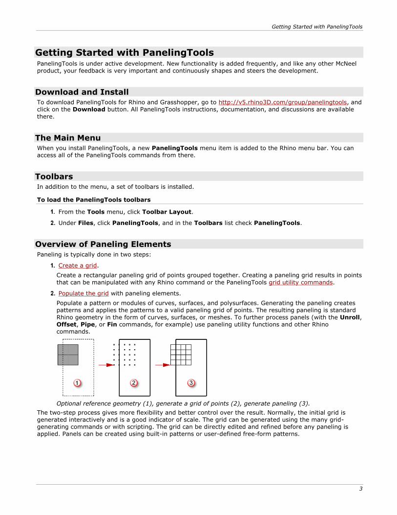
Paneling is typically done in two steps:
Create a grid.
Create a rectangular paneling grid of points grouped together. Creating a paneling grid results in points
that can be manipulated with any Rhino command or the PanelingTools grid utility commands.
Populate the grid with paneling elements.
Populate a pattern or modules of curves, surfaces, and polysurfaces. Generating the paneling creates patterns and applies the patterns to a valid paneling grid of points. The resulting paneling is standard
Rhino geometry in the form of curves, surfaces, or meshes. To further process panels (with the Unroll, Offset, Pipe, or Fin commands, for example) use paneling utility functions and other Rhino commands.
Optional reference geometry (1), generate a grid of points (2), generate paneling (3).
The two-step process gives more flexibility and better control over the result. Normally, the initial grid is generated interactively and is a good indicator of scale. The grid can be generated using the many grid-generating commands or with scripting. The grid can be directly edited and refined before any paneling is applied. Panels can be created using built-in patterns or user-defined free-form patterns.
Getting Started with PanelingTools
4
Create Paneling Grids
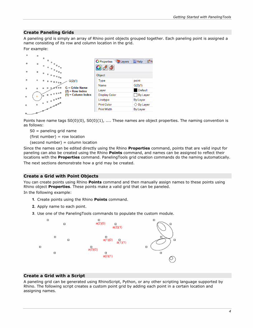
A paneling grid is simply an array of Rhino point objects grouped together. Each paneling point is assigned a name consisting of its row and column location in the grid.
For example:
Points have name tags S0(0)(0), S0(0)(1), .... These names are object properties. The naming convention is as follows:
S0 = paneling grid name
(first number) = row location
(second number) = column location
Since the names can be edited directly using the Rhino Properties command, points that are valid input for paneling can also be created using the Rhino Points command, and names can be assigned to reflect their locations with the Properties command. PanelingTools grid creation commands do the naming automatically.
The next sections demonstrate how a grid may be created.
Create a Grid with Point Objects
You can create points using Rhino Points command and then manually assign names to these points using Rhino object Properties. These points make a valid grid that can be paneled.
In the following example:
Create points using the Rhino Points command.
Apply name to each point.
Use one of the PanelingTools commands to populate the custom module.
Create a Grid with a Script
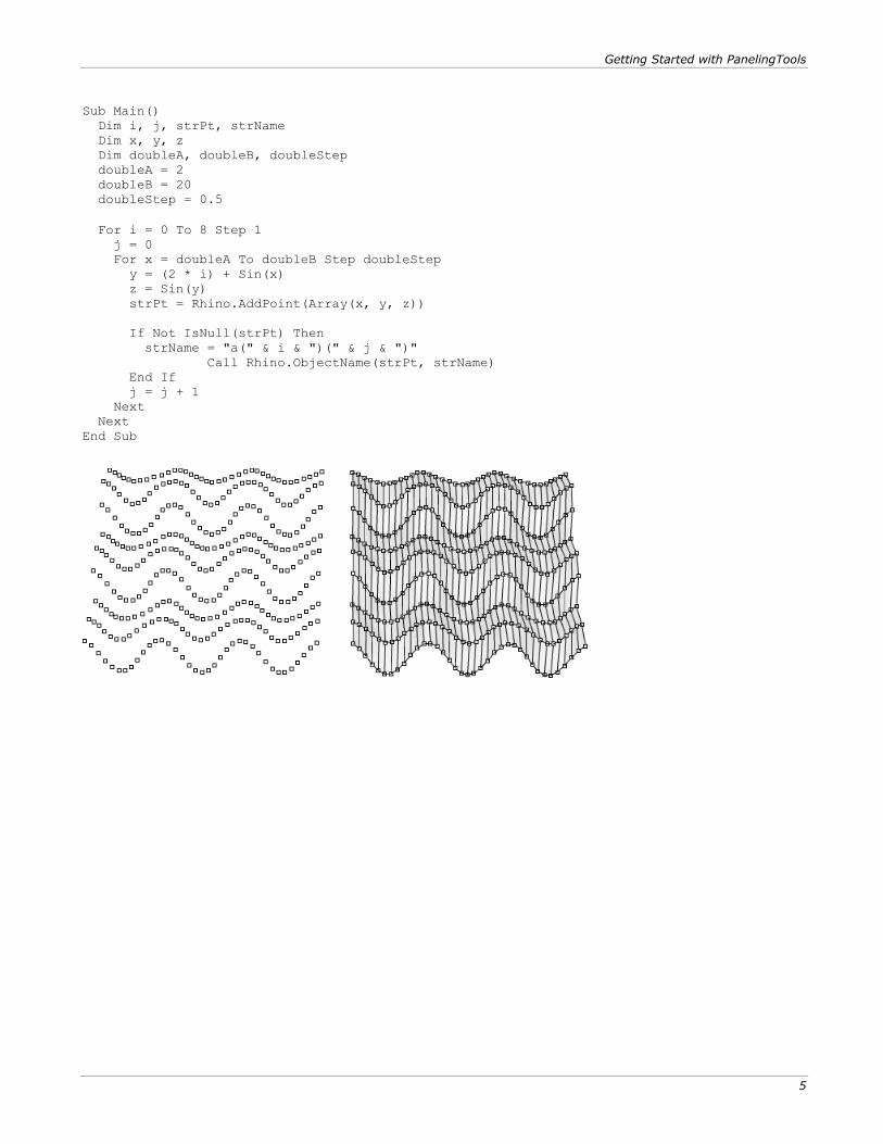
A paneling grid can be generated using RhinoScript, Python, or any other scripting language supported by
Rhino. The following script creates a custom point grid by adding each point in a certain location and assigning names.
Getting Started with PanelingTools
5
Sub Main()
Dim i, j, strPt, strName
Dim x, y, z
Dim doubleA, doubleB, doubleStep
doubleA = 2
doubleB = 20
doubleStep = 0.5
For i = 0 To 8 Step 1
j = 0
For x = doubleA To doubleB Step doubleStep
y = (2 * i) + Sin(x)
z = Sin(y)
strPt = Rhino.AddPoint(Array(x, y, z))
If Not IsNull(strPt) Then
strName = "a(" & i & ")(" & j & ")"
Call Rhino.ObjectName(strPt, strName)
End If
j = j + 1
Next
Next
End Sub
Getting Started with PanelingTools
6
Create a Grid with Grid Commands
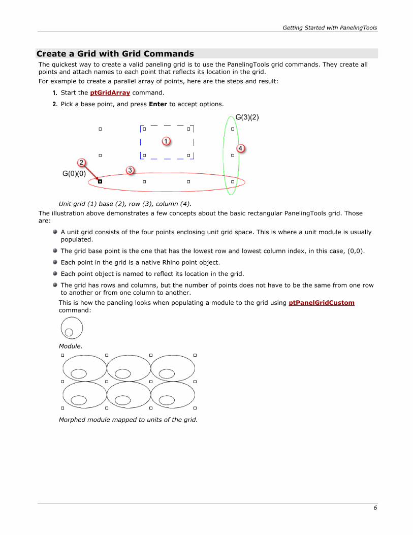
The quickest way to create a valid paneling grid is to use the PanelingTools grid commands. They create all points and attach names to each point that reflects its location in the grid.
For example to create a parallel array of points, here are the steps and result:
Start the ptGridArray command.
Pick a base point, and press Enter to accept options.
Unit grid (1) base (2), row (3), column (4).
The illustration above demonstrates a few concepts about the basic rectangular PanelingTools grid. Those are:
A unit grid consists of the four points enclosing unit grid space. This is where a unit module is usually populated.
The grid base point is the one that has the lowest row and lowest column index, in this case, (0,0).
Each point in the grid is a native Rhino point object.
Each point object is named to reflect its location in the grid.
The grid has rows and columns, but the number of points does not have to be the same from one row
to another or from one column to another.
This is how the paneling looks when populating a module to the grid using ptPanelGridCustom
command:
Module.
Morphed module mapped to units of the grid.
Getting Started with PanelingTools
7
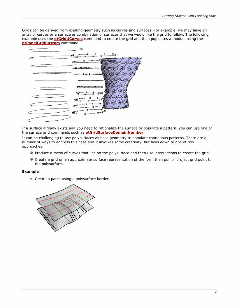
Grids can be derived from existing geometry such as curves and surfaces. For example, we may have an
array of curves or a surface or combination of surfaces that we would like the grid to follow. The following example uses the ptGridUCurves command to create the grid and then populates a module using the ptPanelGridCustom command.
If a surface already exists and you need to rationalize the surface or populate a pattern, you can use one of the surface grid commands such as ptGridSurfaceDomainNumber.
It can be challenging to use polysurfaces as base geometry to populate continuous patterns. There are a number of ways to address this case and it involves some creativity, but boils down to one of two
approaches.
Produce a mesh of curves that lies on the polysurface and then use intersections to create the grid.
Create a grid on an approximate surface representation of the form then pull or project grid point to
the polysurface.
Example
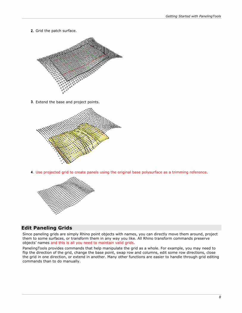
Create a patch using a polysurface border.
Getting Started with PanelingTools
8
Grid the patch surface.
Extend the base and project points.
Use projected grid to create panels using the original base polysurface as a trimming reference.
Edit Paneling Grids
Since paneling grids are simply Rhino point objects with names, you can directly move them around, project them to some surfaces, or transform them in any way you like. All Rhino transform commands preserve objects’ names and this is all you need to maintain valid grids.
PanelingTools provides commands that help manipulate the grid as a whole. For example, you may need to flip the direction of the grid, change the base point, swap row and columns, edit some row directions, close the grid in one direction, or extend in another. Many other functions are easier to handle through grid editing
commands than to do manually.
Getting Started with PanelingTools
9
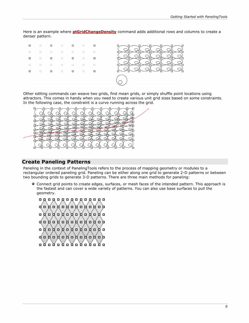
Here is an example where ptGridChangeDensity command adds additional rows and columns to create a
denser pattern.
Other editing commands can weave two grids, find mean grids, or simply shuffle point locations using attractors. This comes in handy when you need to create various unit grid sizes based on some constraints.
In the following case, the constraint is a curve running across the grid.
Create Paneling Patterns
Paneling in the context of PanelingTools refers to the process of mapping geometry or modules to a
rectangular ordered paneling grid. Paneling can be either along one grid to generate 2-D patterns or between two bounding grids to generate 3-D patterns. There are three main methods for paneling:
Connect grid points to create edges, surfaces, or mesh faces of the intended pattern. This approach is the fastest and can cover a wide variety of patterns. You can also use base surfaces to pull the
geometry.
Getting Started with PanelingTools
10
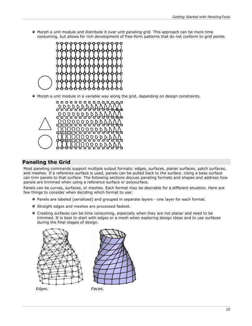
Morph a unit module and distribute it over unit paneling grid. This approach can be more time
consuming, but allows for rich development of free-form patterns that do not conform to grid points.
Morph a unit module in a variable way along the grid, depending on design constraints.
Paneling the Grid
Most paneling commands support multiple output formats: edges, surfaces, planar surfaces, patch surfaces,
and meshes. If a reference surface is used, panels can be pulled back to the surface. Using a base surface can trim panels to that surface. The following sections discuss paneling formats and shapes and address how
panels are trimmed when using a reference surface or polysurface.
Panels can be curves, surfaces, or meshes. Each format may be desirable for a different situation. Here are few things to consider when deciding which format to use:
Panels are labeled (serialized) and grouped in separate layers - one layer for each format.
Straight edges and meshes are processed fastest.
Creating surfaces can be time consuming, especially when they are not planar and need to be
trimmed. It is best to start with edges or a mesh when exploring design ideas and to use surfaces during the final stages of design.
Edges.
Faces.
Getting Started with PanelingTools
11
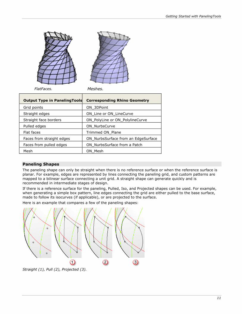
FlatFaces.
Meshes.
Output Type in PanelingTools Corresponding Rhino Geometry
Grid points ON_3DPoint
Straight edges ON_Line or ON_LineCurve
Straight face borders ON_PolyLine or ON_PolylineCurve
Pulled edges ON_NurbsCurve
Flat faces Trimmed ON_Plane
Faces from straight edges ON_NurbsSurface from an EdgeSurface
Faces from pulled edges ON_NurbsSurface from a Patch
Mesh ON_Mesh
Paneling Shapes
The paneling shape can only be straight when there is no reference surface or when the reference surface is planar. For example, edges are represented by lines connecting the paneling grid, and custom patterns are
mapped to a bilinear surface connecting a unit grid. A straight shape can generate quickly and is recommended in intermediate stages of design.
If there is a reference surface for the paneling, Pulled, Iso, and Projected shapes can be used. For example, when generating a simple box pattern, line edges connecting the grid are either pulled to the base surface, made to follow its isocurves (if applicable), or are projected to the surface.
Here is an example that compares a few of the paneling shapes:
Straight (1), Pull (2), Projected (3).
Getting Started with PanelingTools
12
Panel Shapes Description
Straight A line connection between points.
Pull Pulls a straight-line connection to the base surface.
ShortPath The shortest path (geodesic) on the surface between points being connected.
Iso Uses an isocurve between points if possible; otherwise pull back the straight-line curve.
Projected Projects a line connection to the surface.
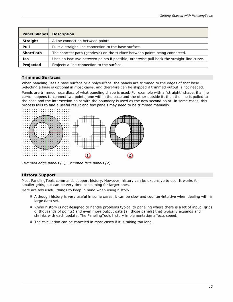
Trimmed Surfaces
When paneling uses a base surface or a polysurface, the panels are trimmed to the edges of that base. Selecting a base is optional in most cases, and therefore can be skipped if trimmed output is not needed.
Panels are trimmed regardless of what paneling shape is used. For example with a “straight” shape, if a line
curve happens to connect two points, one within the base and the other outside it, then the line is pulled to
the base and the intersection point with the boundary is used as the new second point. In some cases, this process fails to find a useful result and few panels may need to be trimmed manually.
Trimmed edge panels (1), Trimmed face panels (2).
History Support
Most PanelingTools commands support history. However, history can be expensive to use. It works for smaller grids, but can be very time consuming for larger ones.
Here are few useful things to keep in mind when using history:
Although history is very useful in some cases, it can be slow and counter-intuitive when dealing with a
large data set.
Rhino history is not designed to handle problems typical to paneling where there is a lot of input (grids
of thousands of points) and even more output data (all those panels) that typically expands and shrinks with each update. The PanelingTools history implementation affects speed.
The calculation can be canceled in most cases if it is taking too long.
Getting Started with PanelingTools
13
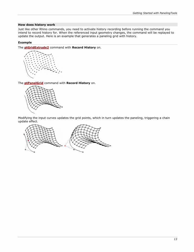
How does history work
Just like other Rhino commands, you need to activate history recording before running the command you intend to record history for. When the referenced input geometry changes, the command will be replayed to update the output. Here is an example that generates a paneling grid with history.
Example
The ptGridExtrude2 command with Record History on.
The ptPanelGrid command with Record History on.
Modifying the input curves updates the grid points, which in turn updates the paneling, triggering a chain
update effect.
Commands: Create Grid Directly
15
Commands: Create Grid Directly The ptGridArray and ptGridArrayPolar commands create a two-dimensional array of points.
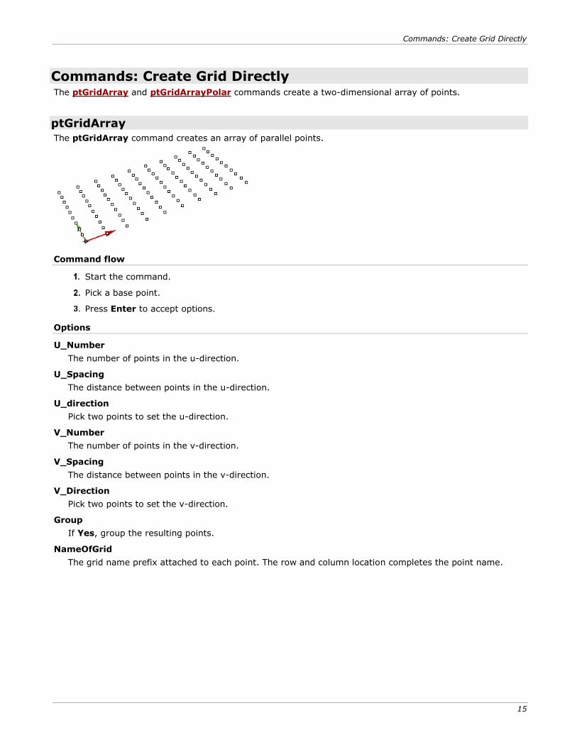
ptGridArray
The ptGridArray command creates an array of parallel points.
Command flow
Start the command.
Pick a base point.
Press Enter to accept options.
Options
U_Number
The number of points in the u-direction.
U_Spacing
The distance between points in the u-direction.
U_direction
Pick two points to set the u-direction.
V_Number
The number of points in the v-direction.
V_Spacing
The distance between points in the v-direction.
V_Direction
Pick two points to set the v-direction.
Group
If Yes, group the resulting points.
NameOfGrid
The grid name prefix attached to each point. The row and column location completes the point name.
Commands: Create Grid Directly
16
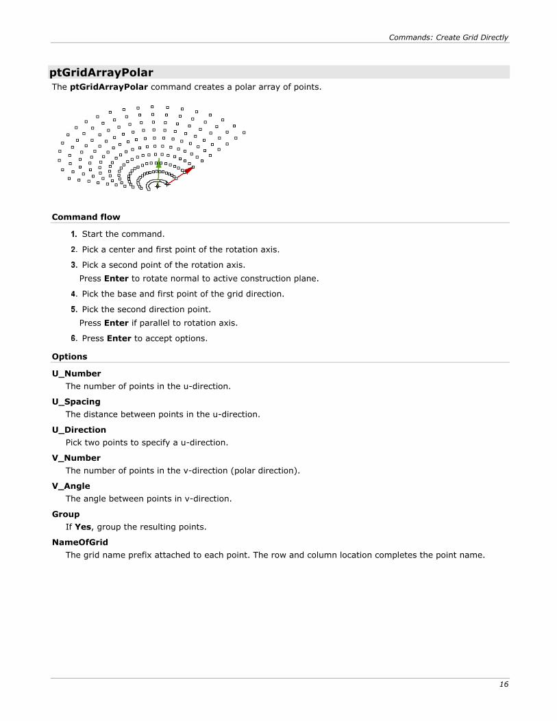
ptGridArrayPolar
The ptGridArrayPolar command creates a polar array of points.
Command flow
Start the command.
Pick a center and first point of the rotation axis.
Pick a second point of the rotation axis.
Press Enter to rotate normal to active construction plane.
Pick the base and first point of the grid direction.
Pick the second direction point.
Press Enter if parallel to rotation axis.
Press Enter to accept options.
Options
U_Number
The number of points in the u-direction.
U_Spacing
The distance between points in the u-direction.
U_Direction
Pick two points to specify a u-direction.
V_Number
The number of points in the v-direction (polar direction).
V_Angle
The angle between points in v-direction.
Group
If Yes, group the resulting points.
NameOfGrid
The grid name prefix attached to each point. The row and column location completes the point name.
Commands: Create Grid from Points
17
Commands: Create Grid from Points The ptGridPoints and ptGridPointsOnSurface commands use pre-defined sets of points to create a paneling grid or to order these points into rows and columns.
These commands define a distance tolerance to identify points that belong to one row or one column. The result may not always be desirable. It is best to define the paneling grid points using PanelingTools commands whenever possible.
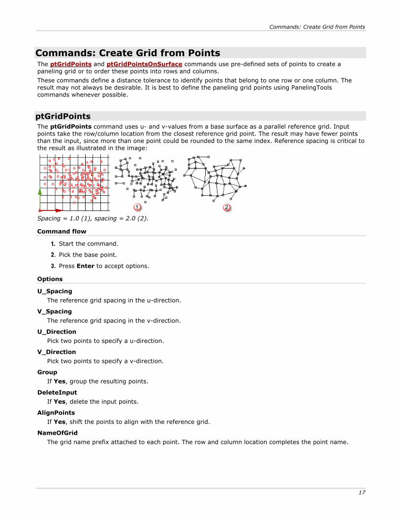
ptGridPoints
The ptGridPoints command uses u- and v-values from a base surface as a parallel reference grid. Input points take the row/column location from the closest reference grid point. The result may have fewer points than the input, since more than one point could be rounded to the same index. Reference spacing is critical to the result as illustrated in the image:
Spacing = 1.0 (1), spacing = 2.0 (2).
Command flow
Start the command.
Pick the base point.
Press Enter to accept options.
Options
U_Spacing
The reference grid spacing in the u-direction.
V_Spacing
The reference grid spacing in the v-direction.
U_Direction
Pick two points to specify a u-direction.
V_Direction
Pick two points to specify a v-direction.
Group
If Yes, group the resulting points.
DeleteInput
If Yes, delete the input points.
AlignPoints
If Yes, shift the points to align with the reference grid.
NameOfGrid
The grid name prefix attached to each point. The row and column location completes the point name.
Commands: Create Grid from Points
18
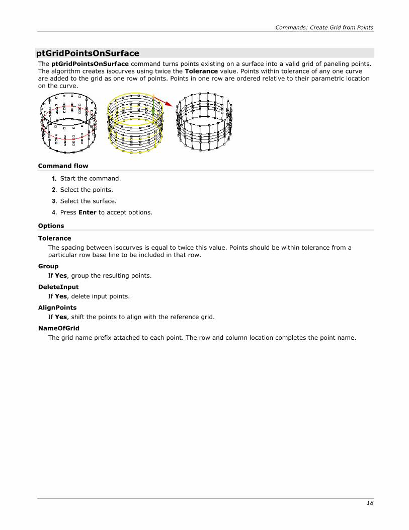
ptGridPointsOnSurface
The ptGridPointsOnSurface command turns points existing on a surface into a valid grid of paneling points. The algorithm creates isocurves using twice the Tolerance value. Points within tolerance of any one curve are added to the grid as one row of points. Points in one row are ordered relative to their parametric location on the curve.
Command flow
Start the command.
Select the points.
Select the surface.
Press Enter to accept options.
Options
Tolerance
The spacing between isocurves is equal to twice this value. Points should be within tolerance from a particular row base line to be included in that row.
Group
If Yes, group the resulting points.
DeleteInput
If Yes, delete input points.
AlignPoints
If Yes, shift the points to align with the reference grid.
NameOfGrid
The grid name prefix attached to each point. The row and column location completes the point name.
Commands: Create Grid from Curves
19
Commands: Create Grid from Curves The ptGridExtrude1, ptGridExtrude2, ptGridUCurves, and ptGridUVCurves commands use input curves to create a paneling grid.
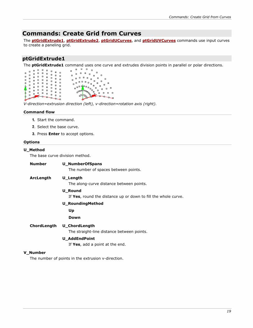
ptGridExtrude1
The ptGridExtrude1 command uses one curve and extrudes division points in parallel or polar directions.
V-direction=extrusion direction (left), v-direction=rotation axis (right).
Command flow
Start the command.
Select the base curve.
Press Enter to accept options.
Options
U_Method
The base curve division method.
Number U_NumberOfSpans
The number of spaces between points.
ArcLength U_Length
The along-curve distance between points.
U_Round
If Yes, round the distance up or down to fill the whole curve.
U_RoundingMethod
Up
Down
ChordLength U_ChordLength
The straight-line distance between points.
U_AddEndPoint
If Yes, add a point at the end.
V_Number
The number of points in the extrusion v-direction.
Commands: Create Grid from Curves
20
V_Method
The array curve divide points in the parallel or polar direction.
Parallel V_Distance
The distance between points.
V_Direction
Pick two points to specify a v-direction.
Polar V_Angle
The angle between rows of points.
V_RotationAxis
Pick two points to specify a rotation axis.
Group
If Yes, group the resulting points.
NameOfGrid
The grid name prefix attached to each point. The row and column location completes the point name.
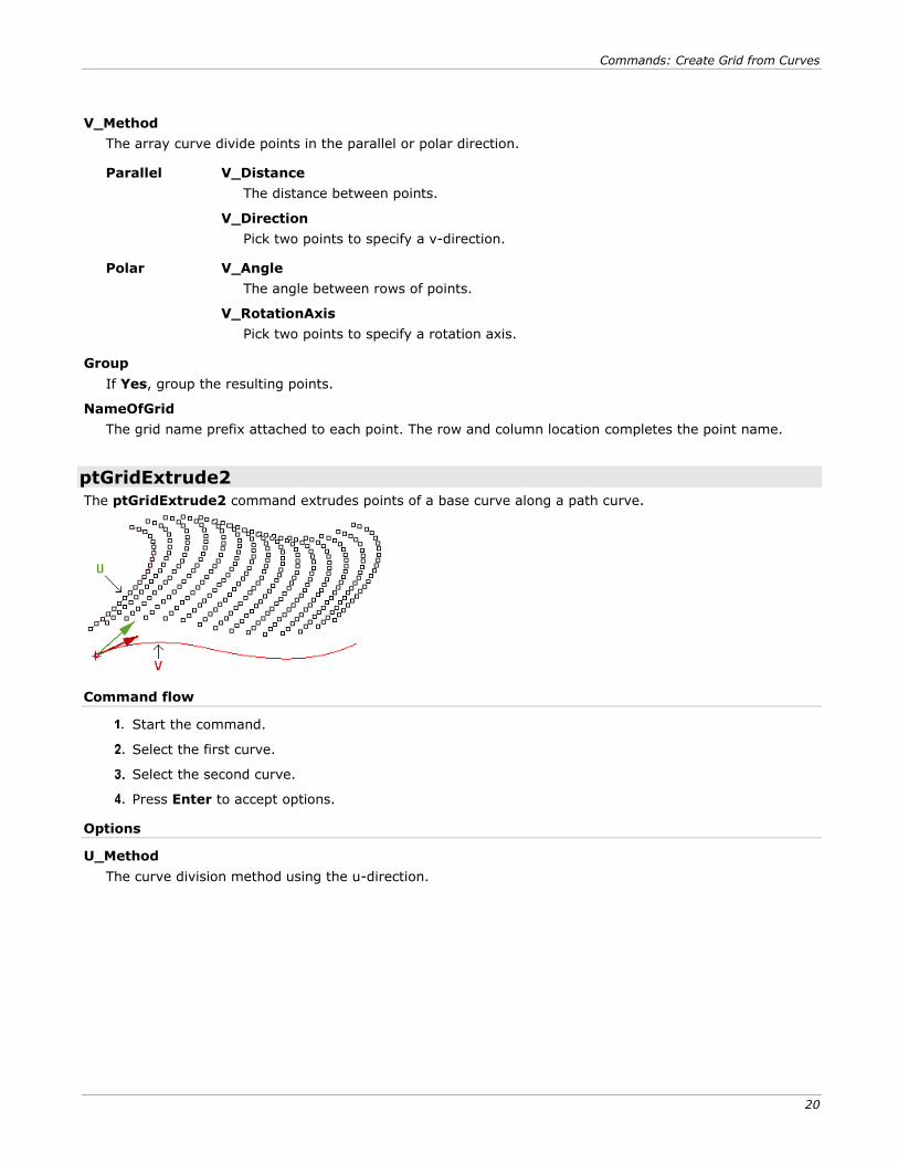
ptGridExtrude2
The ptGridExtrude2 command extrudes points of a base curve along a path curve.
Command flow
Start the command.
Select the first curve.
Select the second curve.
Press Enter to accept options.
Options
U_Method
The curve division method using the u-direction.

Commands: Create Grid from Curves
21
Number U_NumberOfSpans
The number of spaces between points.
ArcLength U_ArcLength
The along-curve distance between points.
U_Round
If Yes, round the distance up or down to fill the whole curve.
U_RoundingMethod
Up
Down
ChordLength U_ChordLength
The straight-line distance between points.
U_AddEndPoint
If Yes, add a point at the end.
V_Method
The curve division method using the v-direction.
Number V_NumberOfSpans
The number of spaces between points.
ArcLength V_ArcLength
The along-curve distance between points.
V_Round
If Yes, round the distance up or down to fill the whole curve.
V_RoundingMethod
Up
Down
ChordLength V_ChordLength
The straight-line distance between points.
V_AddEndPoint
If Yes, add a point at the end.
Group
If Yes, group the resulting points.
NameOfGrid
The grid name prefix attached to each point. The row and column location completes the point name.
SwitchCurves
Change which of the two curves to copy along the other curve points.
Commands: Create Grid from Curves
22
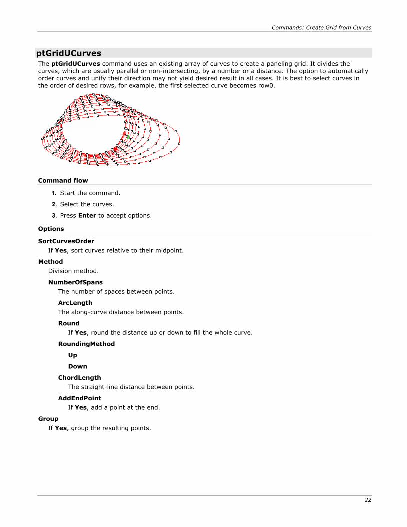
ptGridUCurves
The ptGridUCurves command uses an existing array of curves to create a paneling grid. It divides the curves, which are usually parallel or non-intersecting, by a number or a distance. The option to automatically order curves and unify their direction may not yield desired result in all cases. It is best to select curves in the order of desired rows, for example, the first selected curve becomes row0.
Command flow
Start the command.
Select the curves.
Press Enter to accept options.
Options
SortCurvesOrder
If Yes, sort curves relative to their midpoint.
Method
Division method.
NumberOfSpans
The number of spaces between points.
ArcLength
The along-curve distance between points.
Round
If Yes, round the distance up or down to fill the whole curve.
RoundingMethod
Up
Down
ChordLength
The straight-line distance between points.
AddEndPoint
If Yes, add a point at the end.
Group
If Yes, group the resulting points.
Commands: Create Grid from Curves
23
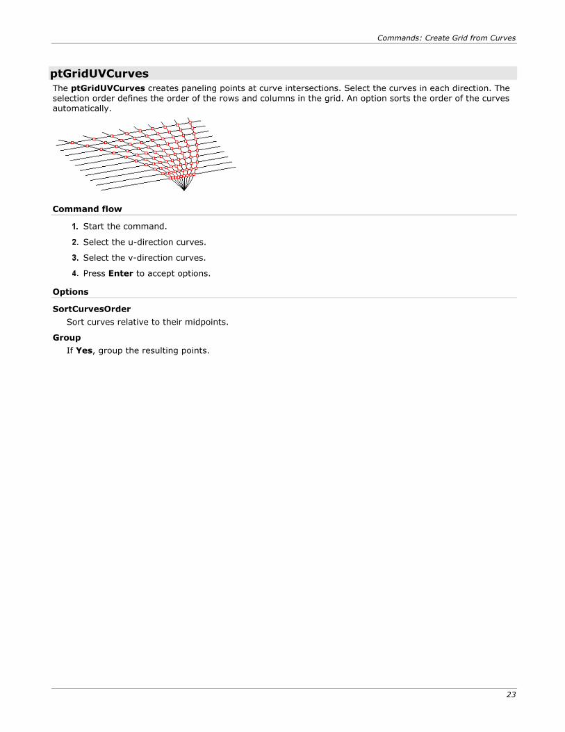
ptGridUVCurves
The ptGridUVCurves creates paneling points at curve intersections. Select the curves in each direction. The selection order defines the order of the rows and columns in the grid. An option sorts the order of the curves automatically.
Command flow
Start the command.
Select the u-direction curves.
Select the v-direction curves.
Press Enter to accept options.
Options
SortCurvesOrder
Sort curves relative to their midpoints.
Group
If Yes, group the resulting points.
Commands: Create Grid from Surfaces
25
Commands: Create Grid from Surfaces The ptGridSurfaceDistance, ptGridSurfaceDomainChord, ptGridSurfaceDomainLength, ptGridSurfaceDomainNumber, and ptGridSurfaceDomainVariable commands use a base NURBS surface to generate a grid.
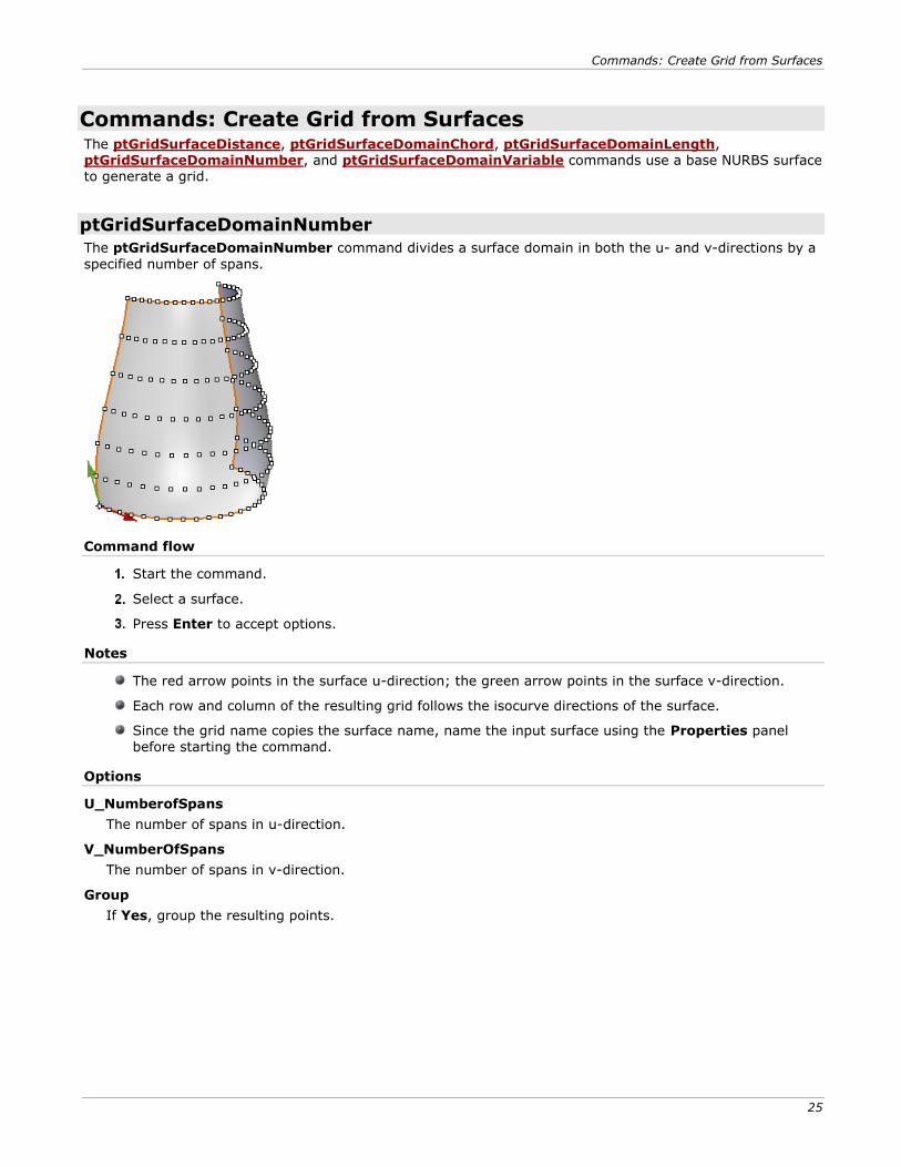
ptGridSurfaceDomainNumber
The ptGridSurfaceDomainNumber command divides a surface domain in both the u- and v-directions by a
specified number of spans.
Command flow
Start the command.
Select a surface.
Press Enter to accept options.
Notes
The red arrow points in the surface u-direction; the green arrow points in the surface v-direction.
Each row and column of the resulting grid follows the isocurve directions of the surface.
Since the grid name copies the surface name, name the input surface using the Properties panel
before starting the command.
Options
U_NumberofSpans
The number of spans in u-direction.
V_NumberOfSpans
The number of spans in v-direction.
Group
If Yes, group the resulting points.
Commands: Create Grid from Surfaces
26
ptGridSurfaceDomainLength
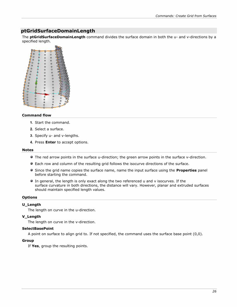
The ptGridSurfaceDomainLength command divides the surface domain in both the u- and v-directions by a specified length.
Command flow
Start the command.
Select a surface.
Specify u- and v-lengths.
Press Enter to accept options.
Notes
The red arrow points in the surface u-direction; the green arrow points in the surface v-direction.
Each row and column of the resulting grid follows the isocurve directions of the surface.
Since the grid name copies the surface name, name the input surface using the Properties panel before starting the command.
In general, the length is only exact along the two referenced u and v isocurves. If the
surface curvature in both directions, the distance will vary. However, planar and extruded surfaces should maintain specified length values.
Options
U_Length
The length on curve in the u-direction.
V_Length
The length on curve in the v-direction.
SelectBasePoint
A point on surface to align grid to. If not specified, the command uses the surface base point (0,0).
Group
If Yes, group the resulting points.
Commands: Create Grid from Surfaces
27
ptGridSurfaceDomainChord
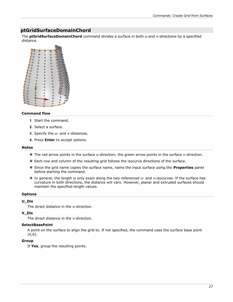
The ptGridSurfaceDomainChord command divides a surface in both u-and v-directions by a specified distance.
Command flow
Start the command.
Select a surface.
Specify the u- and v-distances.
Press Enter to accept options.
Notes
The red arrow points in the surface u-direction; the green arrow points in the surface v-direction.
Each row and column of the resulting grid follows the isocurve directions of the surface.
Since the grid name copies the surface name, name the input surface using the Properties panel before starting the command.
In general, the length is only exact along the two referenced u- and v-isocurves. If the surface has
curvature in both directions, the distance will vary. However, planar and extruded surfaces should maintain the specified length values.
Options
U_Dis
The direct distance in the u-direction.
V_Dis
The direct distance in the v-direction.
SelectBasePoint
A point on the surface to align the grid to. If not specified, the command uses the surface base point
(0,0).
Group
If Yes, group the resulting points.
Commands: Create Grid from Surfaces
28
ptGridSurfaceDomainVariable
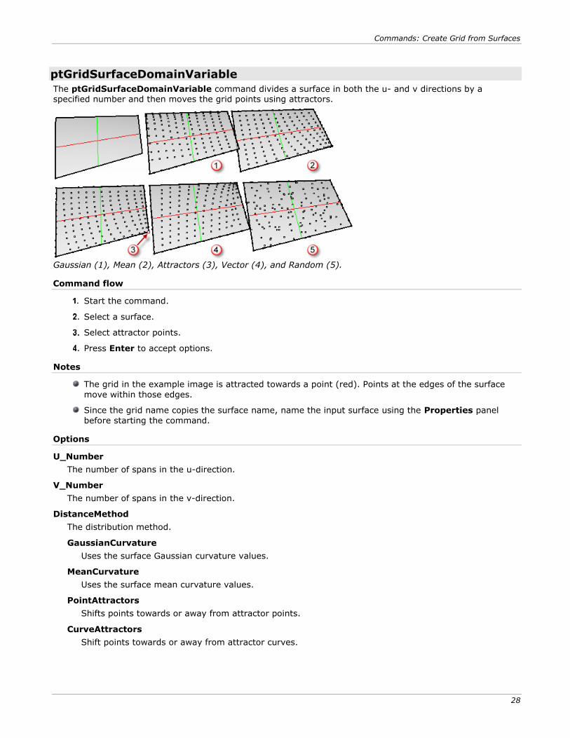
The ptGridSurfaceDomainVariable command divides a surface in both the u- and v directions by a specified number and then moves the grid points using attractors.
Gaussian (1), Mean (2), Attractors (3), Vector (4), and Random (5).
Command flow
Start the command.
Select a surface.
Select attractor points.
Press Enter to accept options.
Notes
The grid in the example image is attracted towards a point (red). Points at the edges of the surface
move within those edges.
Since the grid name copies the surface name, name the input surface using the Properties panel
before starting the command.
Options
U_Number
The number of spans in the u-direction.
V_Number
The number of spans in the v-direction.
DistanceMethod
The distribution method.
GaussianCurvature
Uses the surface Gaussian curvature values.
MeanCurvature
Uses the surface mean curvature values.
PointAttractors
Shifts points towards or away from attractor points.
CurveAttractors
Shift points towards or away from attractor curves.
Commands: Create Grid from Surfaces
29
Vector
Uses a dot product between a vector and the surface normal at each point.
Random
Shifts points by a random amount.
Bitmap
Uses an image to drive the attraction.
AttractMethod
The direction the points are moved with respect to the attractors. If the DistanceMethod is MeanCurvature or GaussianCurvature, the points are attracted toward or away from the highest curvature.
Away
Toward
Magnitude
Reduces or magnifies the distance variations.
Group
If Yes, group the resulting points.
ptGridSurfaceDistance
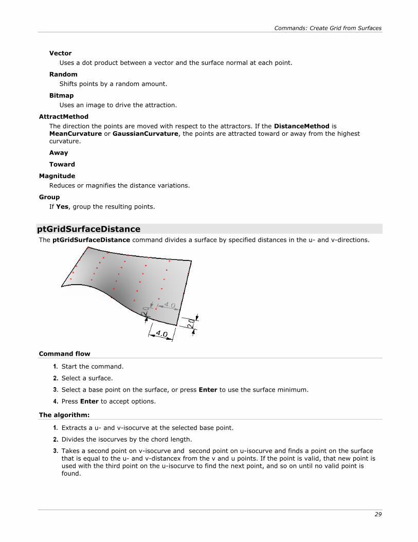
The ptGridSurfaceDistance command divides a surface by specified distances in the u- and v-directions.
Command flow
Start the command.
Select a surface.
Select a base point on the surface, or press Enter to use the surface minimum.
Press Enter to accept options.
The algorithm:
Extracts a u- and v-isocurve at the selected base point.
Divides the isocurves by the chord length.
Takes a second point on v-isocurve and second point on u-isocurve and finds a point on the surface
that is equal to the u- and v-distancex from the v and u points. If the point is valid, that new point is used with the third point on the u-isocurve to find the next point, and so on until no valid point is
found.
Commands: Create Grid from Surfaces
30
Note
Since this command uses an algorithm where every new point depends on previously created points; it may not give complete coverage. The Extend option may help creating better coverage.
Since the grid name copies the surface name, name the input surface using the Properties panel
before starting the command.
A point on the surface can be used as a base.
Options
U_Distance
The distance in the u-direction.
V_Distance
The distance in the v-direction.
Extend
Extend the surface before dividing it to get better coverage.
Group
If Yes, group the resulting points.
Commands: Create Grid from Projected Curves
31
Commands: Create Grid from Projected Curves The ptGridCurve and ptGridCurve2 commands create a grid a from polysurface or a surface without using its uv-directions.
The general algorithm:
The input curve is arrayed the specified distance or angle and direction.
The user defines the direction to project curves towards the base surface or polysurface.
The curves are then projected and the resulting curves are joined and cleaned.
The new curves are used to divide by the number or distance.
If the curves are in both directions, grid points are extracted from their intersections.
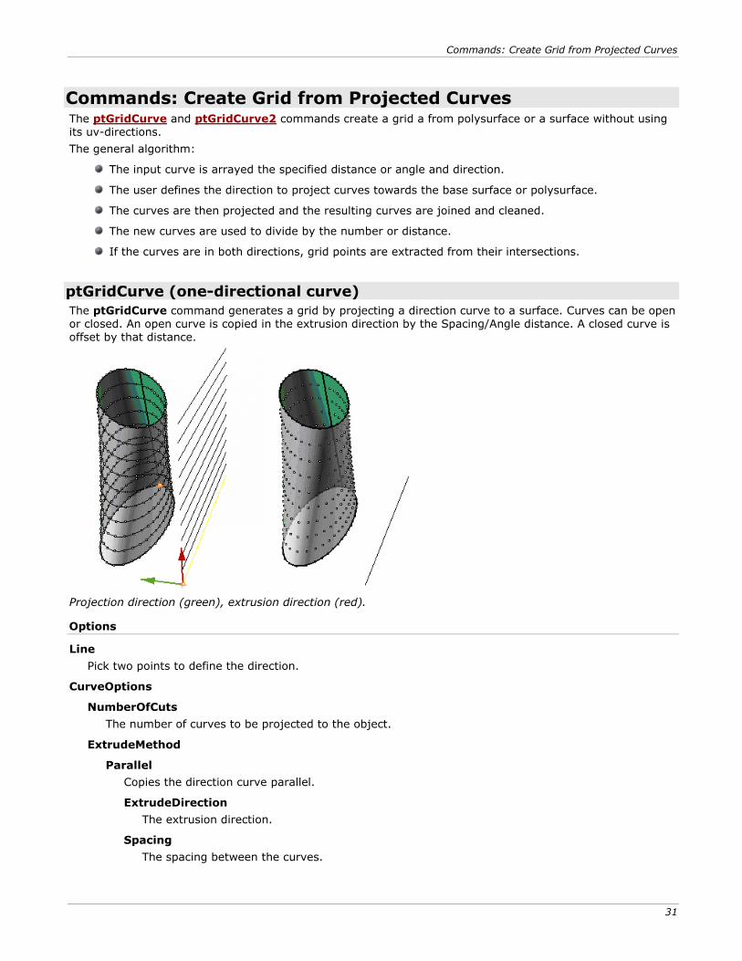
ptGridCurve (one-directional curve)
The ptGridCurve command generates a grid by projecting a direction curve to a surface. Curves can be open or closed. An open curve is copied in the extrusion direction by the Spacing/Angle distance. A closed curve is offset by that distance.
Projection direction (green), extrusion direction (red).
Options
Line
Pick two points to define the direction.
CurveOptions
NumberOfCuts
The number of curves to be projected to the object.
ExtrudeMethod
Parallel
Copies the direction curve parallel.
ExtrudeDirection
The extrusion direction.
Spacing
The spacing between the curves.
Commands: Create Grid from Projected Curves
32
Polar
Copies the direction curve around the object origin.
Angle
The angle between the curves.
ProjectionDirection
The direction the curves are projected.
GridOptions
Method
The curves division method.
Number NumberOfSpans
The number of spaces between points.
ArcLength Length
The along-curve distance between points.
Round
If Yes, round distances to fill the span of the curve.
RoundingMethod
Up
Down
ChordLength Distance
The straight-line distance between points.
AddEndPoint
If Yes, add a point at the end.
Group
If Yes, group the resulting points.
NameOfGrid
The grid name prefix is attached to each point. The row and column location completes the point name.
Commands: Create Grid from Projected Curves
33
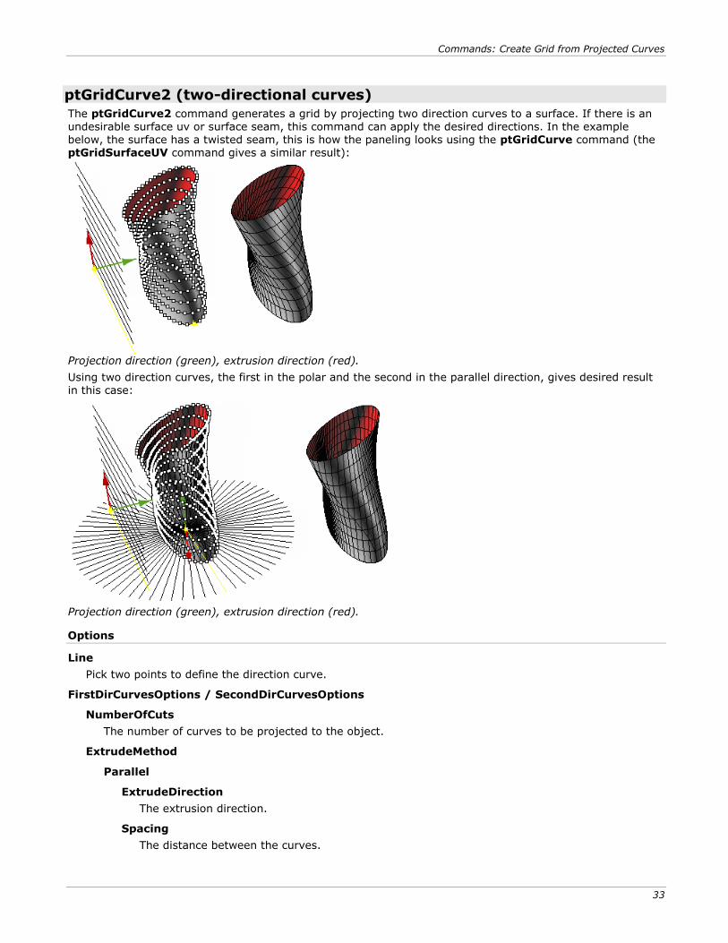
ptGridCurve2 (two-directional curves)
The ptGridCurve2 command generates a grid by projecting two direction curves to a surface. If there is an undesirable surface uv or surface seam, this command can apply the desired directions. In the example below, the surface has a twisted seam, this is how the paneling looks using the ptGridCurve command (the ptGridSurfaceUV command gives a similar result):
Projection direction (green), extrusion direction (red).
Using two direction curves, the first in the polar and the second in the parallel direction, gives desired result in this case:
Projection direction (green), extrusion direction (red).
Options
Line
Pick two points to define the direction curve.
FirstDirCurvesOptions / SecondDirCurvesOptions
NumberOfCuts
The number of curves to be projected to the object.
ExtrudeMethod
Parallel
ExtrudeDirection
The extrusion direction.
Spacing
The distance between the curves.
Commands: Create Grid from Projected Curves
34
Polar
Angle
The angle between the curves.
ProjectionDirection
The direction the curves are projected.
Group
If Yes, group the resulting points.
NameOfGrid
The grid name prefix is attached to each point. The row and column location completes the point name.
Commands: 2-D Connecting Patterns
35
Commands: 2-D Connecting Patterns PanelingTools supports generating paneling patterns either by connecting paneling grid points or by mapping a given module to a unit grid.
Connecting paneling points is faster and does not involve time-consuming mapping or morphing.
ptPanelGrid
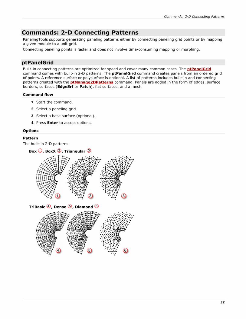
Built-in connecting patterns are optimized for speed and cover many common cases. The ptPanelGrid
command comes with built-in 2-D patterns. The ptPanelGrid command creates panels from an ordered grid of points. A reference surface or polysurface is optional. A list of patterns includes built-in and connecting patterns created with the ptManage2DPatterns command. Panels are added in the form of edges, surface borders, surfaces (EdgeSrf or Patch), flat surfaces, and a mesh.
Command flow
Start the command.
Select a paneling grid.
Select a base surface (optional).
Press Enter to accept options.
Options
Pattern
The built-in 2-D patterns.
Box , BoxX , Triangular
TriBasic , Dense , Diamond
Commands: 2-D Connecting Patterns
36
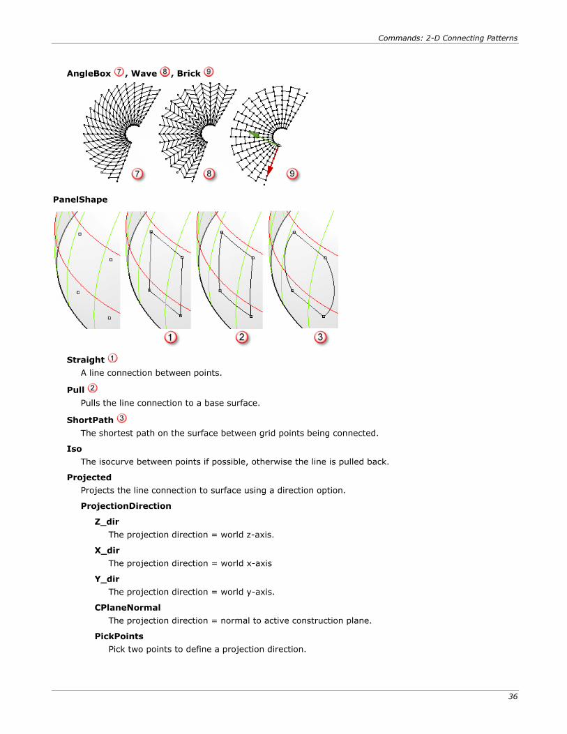
AngleBox , Wave , Brick
PanelShape
Straight
A line connection between points.
Pull
Pulls the line connection to a base surface.
ShortPath
The shortest path on the surface between grid points being connected.
Iso
The isocurve between points if possible, otherwise the line is pulled back.
Projected
Projects the line connection to surface using a direction option.
ProjectionDirection
Z_dir
The projection direction = world z-axis.
X_dir
The projection direction = world x-axis
Y_dir
The projection direction = world y-axis.
CPlaneNormal
The projection direction = normal to active construction plane.
PickPoints
Pick two points to define a projection direction.
Commands: 2-D Connecting Patterns
37
AddEdges
Add edge panels to a new layer. Edges are serialized.
AddFacesBorder
Add border curves panels to a new layer. Borders are serialized.
AddFaces
Add face panels (Patch or EdgeSrf) to a new layer. Faces are serialized.
AddFlatFaces
Create planar faces. Faces may not join. Faces are serialized and added to a new layer.
FlatFaceMethod
Specify how flat panels are calculated.
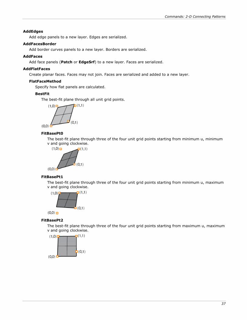
BestFit
The best-fit plane through all unit grid points.
FitBasePt0
The best-fit plane through three of the four unit grid points starting from minimum u, minimum v and going clockwise.
FitBasePt1
The best-fit plane through three of the four unit grid points starting from minimum u, maximum v and going clockwise.
FitBasePt2
The best-fit plane through three of the four unit grid points starting from maximum u, maximum
v and going clockwise.
Commands: 2-D Connecting Patterns
38
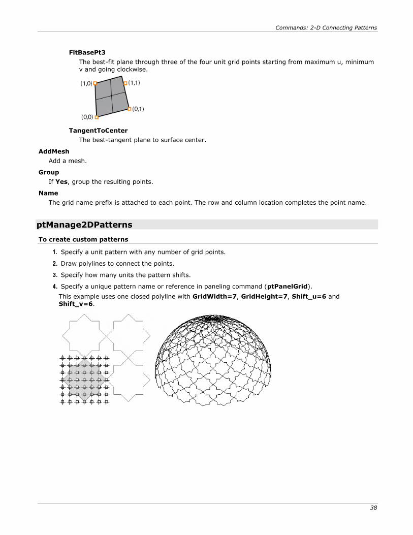
FitBasePt3
The best-fit plane through three of the four unit grid points starting from maximum u, minimum v and going clockwise.
TangentToCenter
The best-tangent plane to surface center.
AddMesh
Add a mesh.
Group
If Yes, group the resulting points.
Name
The grid name prefix is attached to each point. The row and column location completes the point name.
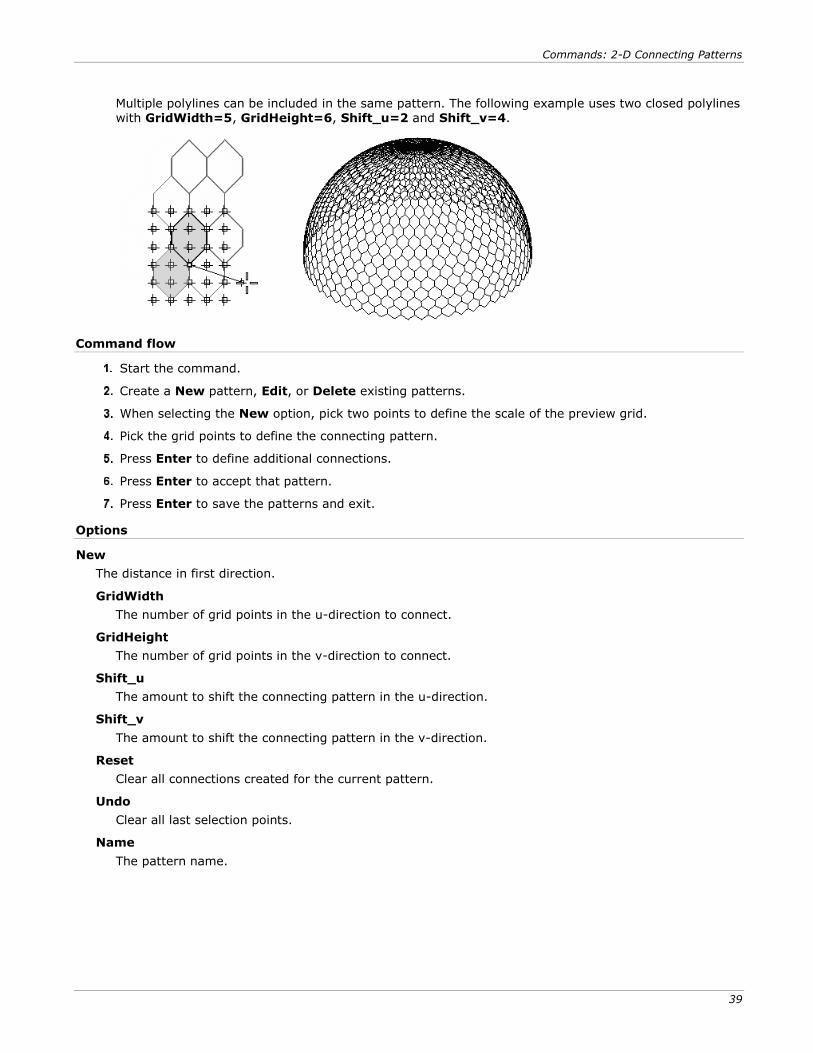
ptManage2DPatterns
To create custom patterns
Specify a unit pattern with any number of grid points.
Draw polylines to connect the points.
Specify how many units the pattern shifts.
Specify a unique pattern name or reference in paneling command (ptPanelGrid).
This example uses one closed polyline with GridWidth=7, GridHeight=7, Shift_u=6 and Shift_v=6.
Commands: 2-D Connecting Patterns
39
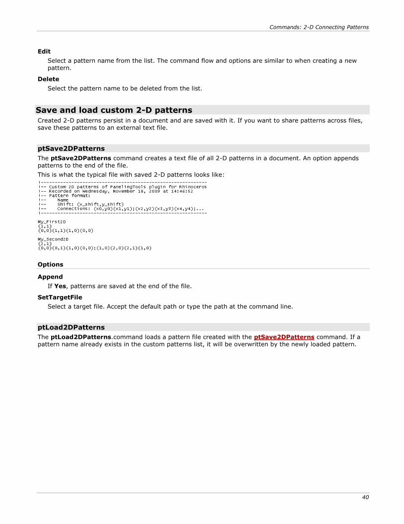
Multiple polylines can be included in the same pattern. The following example uses two closed polylines
with GridWidth=5, GridHeight=6, Shift_u=2 and Shift_v=4.
Command flow
Start the command.
Create a New pattern, Edit, or Delete existing patterns.
When selecting the New option, pick two points to define the scale of the preview grid.
Pick the grid points to define the connecting pattern.
Press Enter to define additional connections.
Press Enter to accept that pattern.
Press Enter to save the patterns and exit.
Options
New
The distance in first direction.
GridWidth
The number of grid points in the u-direction to connect.
GridHeight
The number of grid points in the v-direction to connect.
Shift_u
The amount to shift the connecting pattern in the u-direction.
Shift_v
The amount to shift the connecting pattern in the v-direction.
Reset
Clear all connections created for the current pattern.
Undo
Clear all last selection points.
Name
The pattern name.
Commands: 2-D Connecting Patterns
40
Edit
Select a pattern name from the list. The command flow and options are similar to when creating a new pattern.
Delete
Select the pattern name to be deleted from the list.
Save and load custom 2-D patterns
Created 2-D patterns persist in a document and are saved with it. If you want to share patterns across files, save these patterns to an external text file.
ptSave2DPatterns
The ptSave2DPatterns command creates a text file of all 2-D patterns in a document. An option appends
patterns to the end of the file.
This is what the typical file with saved 2-D patterns looks like:
Options
Append
If Yes, patterns are saved at the end of the file.
SetTargetFile
Select a target file. Accept the default path or type the path at the command line.
ptLoad2DPatterns
The ptLoad2DPatterns.command loads a pattern file created with the ptSave2DPatterns command. If a pattern name already exists in the custom patterns list, it will be overwritten by the newly loaded pattern.
Commands: 3-D Connecting Patterns
41
Commands: 3-D Connecting Patterns The ptPanel3D command comes with built-in 3-D patterns. The command help create edges, faces, and solids.
ptPanel3D
The ptPanel3D command creates a panel from two grids. A list of patterns includes built-in and user-defined panels. Panels are added in the form of edges, surfaces, and polysurfaces. Spacing of unit patterns depends
on the grid spacing.
Command flow
Start the command.
Select the first paneling grid. Set options for pattern in this step.
Select the second paneling grid.
Options
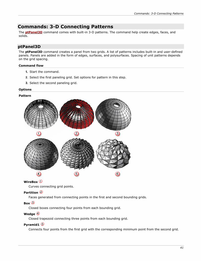
Pattern
WireBox
Curves connecting grid points.
Partition
Faces generated from connecting points in the first and second bounding grids.
Box
Closed boxes connecting four points from each bounding grid.
Wedge
Closed trapezoid connecting three points from each bounding grid.
Pyramid1
Connects four points from the first grid with the corresponding minimum point from the second grid.
Commands: 3-D Connecting Patterns
42
Pyramid2
Connect four points from the first grid that extend over two spans with the corresponding middle point
in the second grid.
User-defined
Group
If Yes, group the resulting points.
Name
The grid name prefix attached to each point. The row and column location completes the point name.
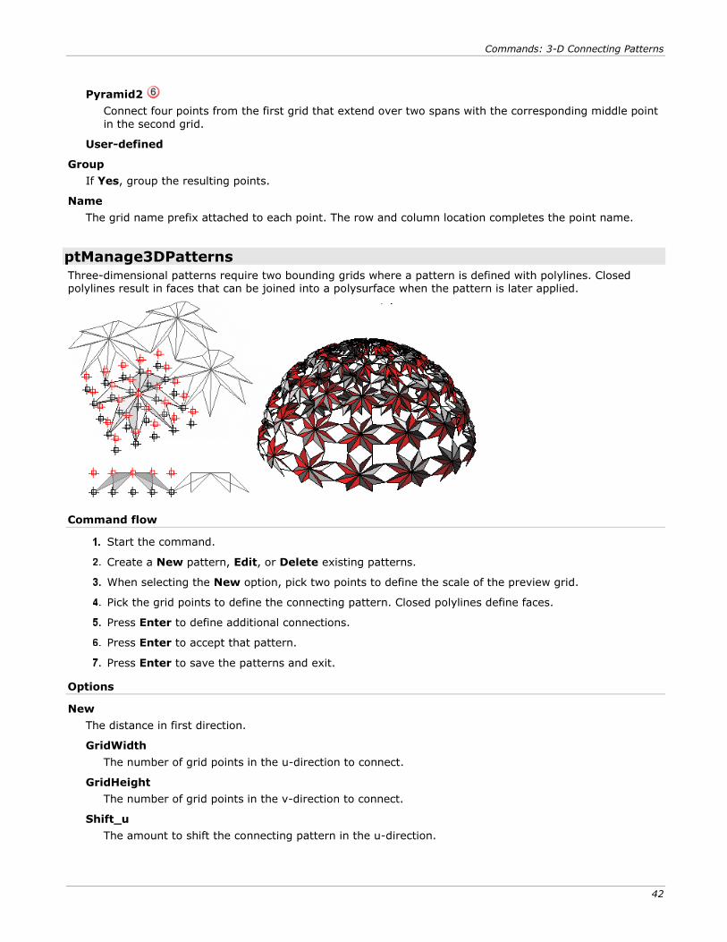
ptManage3DPatterns
Three-dimensional patterns require two bounding grids where a pattern is defined with polylines. Closed polylines result in faces that can be joined into a polysurface when the pattern is later applied.
Command flow
Start the command.
Create a New pattern, Edit, or Delete existing patterns.
When selecting the New option, pick two points to define the scale of the preview grid.
Pick the grid points to define the connecting pattern. Closed polylines define faces.
Press Enter to define additional connections.
Press Enter to accept that pattern.
Press Enter to save the patterns and exit.
Options
New
The distance in first direction.
GridWidth
The number of grid points in the u-direction to connect.
GridHeight
The number of grid points in the v-direction to connect.
Shift_u
The amount to shift the connecting pattern in the u-direction.
Commands: 3-D Connecting Patterns
43
Shift_v
The amount to shift the connecting pattern in the v-direction.
Reset
Clear all connections created for the current pattern.
Undo
Clear all last selection points.
Name
The pattern name.
Edit
Select a pattern name from the list. The command flow and options are similar to when creating a new pattern.
Delete
Select the pattern name to be deleted from the list.
Save and load 3-D custom patterns
Created 2-D patterns persist in a document and are saves with it, but if you want to share patterns across files, save these patterns to an external text file.
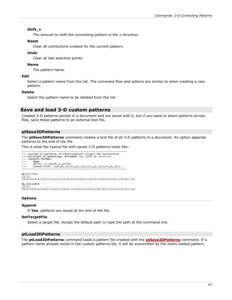
ptSave3DPatterns
The ptSave3DPatterns command creates a text file of all 3-D patterns in a document. An option appends
patterns to the end of the file.
This is what the typical file with saved 3-D patterns looks like:
Options
Append
If Yes, patterns are saved at the end of the file.
SetTargetFile
Select a target file. Accept the default path or type the path at the command line.
ptLoad3DPatterns
The ptLoad3DPatterns command loads a pattern file created with the ptSave3DPatterns command. If a pattern name already exists in the custom patterns list, it will be overwritten by the newly loaded pattern.
Commands: Map to Unit Grid
45
Commands: Map to Unit Grid The ptPanelGridCustom, ptPanelGridCustomVariable, ptPanel3DCustom, ptPanel3DCustomVariable, and ptOrientToGrid commands create panels from a unit grid.
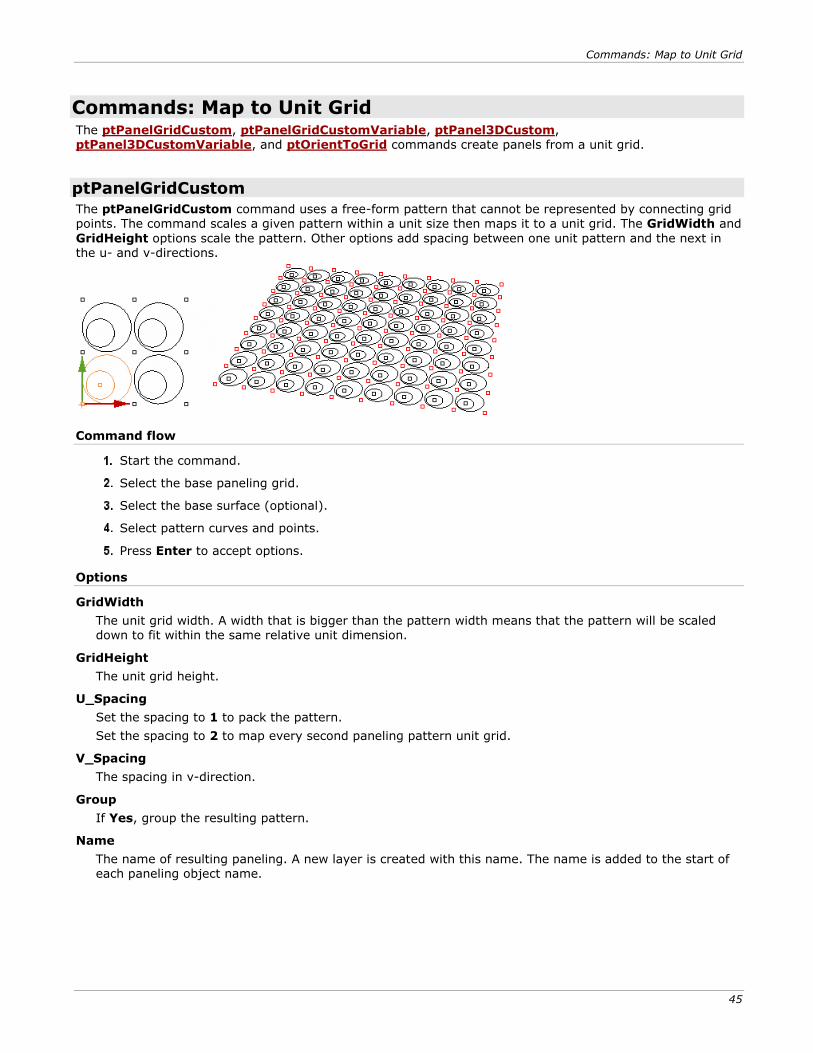
ptPanelGridCustom
The ptPanelGridCustom command uses a free-form pattern that cannot be represented by connecting grid points. The command scales a given pattern within a unit size then maps it to a unit grid. The GridWidth and
GridHeight options scale the pattern. Other options add spacing between one unit pattern and the next in the u- and v-directions.
Command flow
Start the command.
Select the base paneling grid.
Select the base surface (optional).
Select pattern curves and points.
Press Enter to accept options.
Options
GridWidth
The unit grid width. A width that is bigger than the pattern width means that the pattern will be scaled down to fit within the same relative unit dimension.
GridHeight
The unit grid height.
U_Spacing
Set the spacing to 1 to pack the pattern.
Set the spacing to 2 to map every second paneling pattern unit grid.
V_Spacing
The spacing in v-direction.
Group
If Yes, group the resulting pattern.
Name
The name of resulting paneling. A new layer is created with this name. The name is added to the start of each paneling object name.
Commands: Map to Unit Grid
46
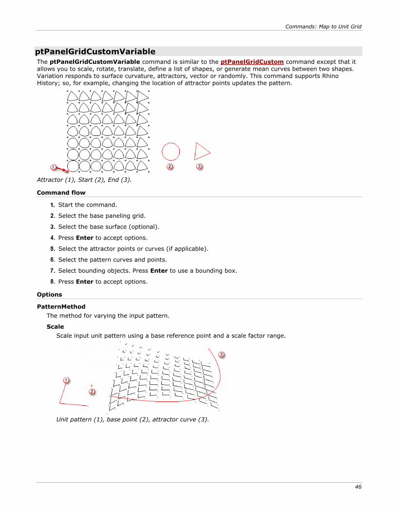
ptPanelGridCustomVariable
The ptPanelGridCustomVariable command is similar to the ptPanelGridCustom command except that it allows you to scale, rotate, translate, define a list of shapes, or generate mean curves between two shapes. Variation responds to surface curvature, attractors, vector or randomly. This command supports Rhino History; so, for example, changing the location of attractor points updates the pattern.
Attractor (1), Start (2), End (3).
Command flow
Start the command.
Select the base paneling grid.
Select the base surface (optional).
Press Enter to accept options.
Select the attractor points or curves (if applicable).
Select the pattern curves and points.
Select bounding objects. Press Enter to use a bounding box.
Press Enter to accept options.
Options
PatternMethod
The method for varying the input pattern.
Scale
Scale input unit pattern using a base reference point and a scale factor range.
Unit pattern (1), base point (2), attractor curve (3).
Commands: Map to Unit Grid
47
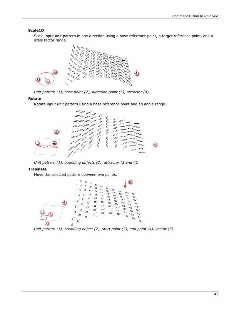
Scale1D
Scale input unit pattern in one direction using a base reference point, a target reference point, and a scale factor range.
Unit pattern (1), base point (2), direction point (3), attractor (4).
Rotate
Rotate input unit pattern using a base reference point and an angle range.
Unit pattern (1), bounding objects (2), attractor (3 and 4).
Translate
Move the selected pattern between two points.
Unit pattern (1), bounding object (2), start point (3), end point (4), vector (5).
Commands: Map to Unit Grid
48
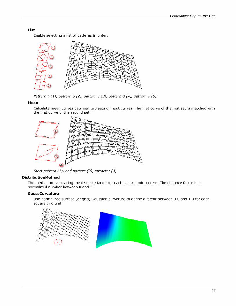
List
Enable selecting a list of patterns in order.
Pattern a (1), pattern b (2), pattern c (3), pattern d (4), pattern e (5).
Mean
Calculate mean curves between two sets of input curves. The first curve of the first set is matched with the first curve of the second set.
Start pattern (1), end pattern (2), attractor (3).
DistributionMethod
The method of calculating the distance factor for each square unit pattern. The distance factor is a normalized number between 0 and 1.
GaussCurvature
Use normalized surface (or grid) Gaussian curvature to define a factor between 0.0 and 1.0 for each square grid unit.

Commands: Map to Unit Grid
49
MeanCurvature
Use normalized surface (or grid) mean curvature to define a factor between 0.0 and 1.0 for each square grid unit.
PointAttractors
The factor is based on the normalized distance from a set of points.
CurveAttractors
The factor is based on the normalized distance from a set of curves.
Vector
The factor is based on the normalized angle with the input vector.
Random
Randomly assign a factor between 0.0 and 1.0 for each square grid unit.
PullCurves
Pull the resulting pattern curves to the base surface (if available).
Group
If Yes, group the resulting pattern.
Name
The name of resulting paneling. A new layer is created with this name. The name is added to the start of each paneling object name.
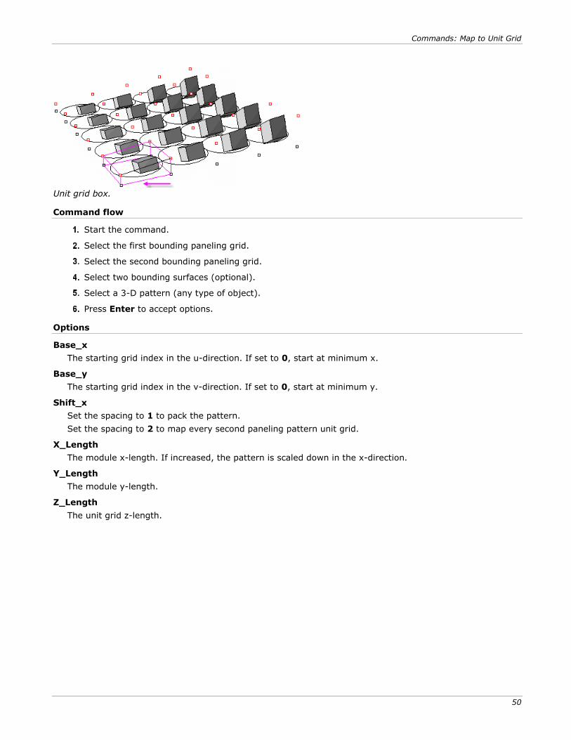
ptPanel3DCustom
The ptPanel3DCustom command scales a given 3-D pattern bounding box to a unit grid box. (A unit grid is a box bounded by four points from the first bounding grid and four points from the second bounding grid.) Options scale the pattern and add spacing between each unit pattern and the next in u and v directions.
The following example uses two bounding grids and maps the bounding box of the 3-D module to each of the
one-unit grid boxes.
Default (left); increase length in the y-direction (right).
Commands: Map to Unit Grid
50
Unit grid box.
Command flow
Start the command.
Select the first bounding paneling grid.
Select the second bounding paneling grid.
Select two bounding surfaces (optional).
Select a 3-D pattern (any type of object).
Press Enter to accept options.
Options
Base_x
The starting grid index in the u-direction. If set to 0, start at minimum x.
Base_y
The starting grid index in the v-direction. If set to 0, start at minimum y.
Shift_x
Set the spacing to 1 to pack the pattern.
Set the spacing to 2 to map every second paneling pattern unit grid.
X_Length
The module x-length. If increased, the pattern is scaled down in the x-direction.
Y_Length
The module y-length.
Z_Length
The unit grid z-length.

Commands: Map to Unit Grid
51
ptOrientToGrid
The ptOrientToGrid command populates 3-D pattern objects to one paneling grid. This command gives additional control to define the input pattern base point, scale, and whether the mapping is rigid or deformed. The following example is a rigid transform that uses three reference points.
Base point (1), x-reference (2), y-reference (3).
If a fourth reference point is set, the object will be deformed when populating the grid.
Base point (1), x_ref (2), y_ref (3), 4th ref point (4).
Command flow
Start the command.
Select the module objects. Press Enter when done.
Select the module base point, x-reference point and y-reference point.
If the module needs to maintain its size, press Enter.
Or select al fourth point if the module should be deformed.
Select the paneling grid.
Press Enter to accept options.
Options
Base_x
The starting grid index in the u-direction. If set to 0, start at minimum x.
Base_y
The starting grid index in the v-direction. If set to 0, start at minimum y.
Shift_x
Set the spacing to 1 to pack the pattern.
Set the spacing to 2 to map every second paneling pattern unit grid.
Shift_y
The shift amount in the y-direction.
Commands: Map to Unit Grid
52
X_Length
The number of x grid points to stretch along.
Y_Length
The unit grid y-length.
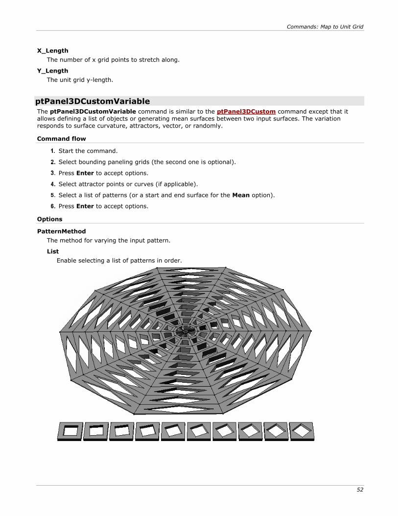
ptPanel3DCustomVariable
The ptPanel3DCustomVariable command is similar to the ptPanel3DCustom command except that it allows defining a list of objects or generating mean surfaces between two input surfaces. The variation responds to surface curvature, attractors, vector, or randomly.
Command flow
Start the command.
Select bounding paneling grids (the second one is optional).
Press Enter to accept options.
Select attractor points or curves (if applicable).
Select a list of patterns (or a start and end surface for the Mean option).
Press Enter to accept options.
Options
PatternMethod
The method for varying the input pattern.
List
Enable selecting a list of patterns in order.
Commands: Map to Unit Grid
53
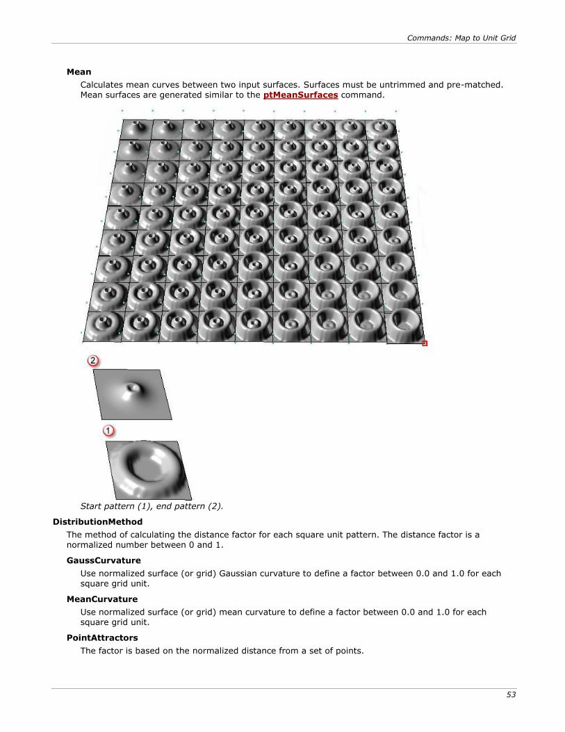
Mean
Calculates mean curves between two input surfaces. Surfaces must be untrimmed and pre-matched. Mean surfaces are generated similar to the ptMeanSurfaces command.
Start pattern (1), end pattern (2).
DistributionMethod
The method of calculating the distance factor for each square unit pattern. The distance factor is a
normalized number between 0 and 1.
GaussCurvature
Use normalized surface (or grid) Gaussian curvature to define a factor between 0.0 and 1.0 for each square grid unit.
MeanCurvature
Use normalized surface (or grid) mean curvature to define a factor between 0.0 and 1.0 for each square grid unit.
PointAttractors
The factor is based on the normalized distance from a set of points.
Commands: Map to Unit Grid
54
CurveAttractors
The factor is based on the normalized distance from a set of curves.
Vector
The factor is based on the normalized angle with the input vector.
Random
Randomly assign a factor between 0.0 and 1.0 for each square grid unit.
Group
If Yes, group the resulting pattern.
Name
The name of resulting paneling. A new layer is created with this name. The name is added to the start of each paneling object name.
Paneling Planar Quadrangles
55
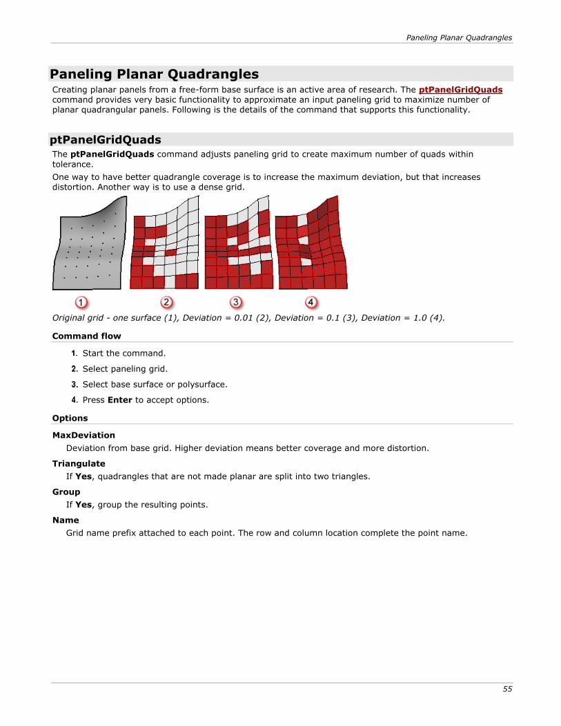
Paneling Planar Quadrangles Creating planar panels from a free-form base surface is an active area of research. The ptPanelGridQuads command provides very basic functionality to approximate an input paneling grid to maximize number of planar quadrangular panels. Following is the details of the command that supports this functionality.
ptPanelGridQuads
The ptPanelGridQuads command adjusts paneling grid to create maximum number of quads within
tolerance.
One way to have better quadrangle coverage is to increase the maximum deviation, but that increases distortion. Another way is to use a dense grid.
Original grid - one surface (1), Deviation = 0.01 (2), Deviation = 0.1 (3), Deviation = 1.0 (4).
Command flow
Start the command.
Select paneling grid.
Select base surface or polysurface.
Press Enter to accept options.
Options
MaxDeviation
Deviation from base grid. Higher deviation means better coverage and more distortion.
Triangulate
If Yes, quadrangles that are not made planar are split into two triangles.
Group
If Yes, group the resulting points.
Name
Grid name prefix attached to each point. The row and column location complete the point name.
Commands: Paneling without a Grid
57
Commands: Paneling without a Grid The ptPanelSubDivide, ptPanelRandomPoints, and ptTriangulatePoints commands do not create a base grid, but use either polylines or points on surface as an input to panel.
ptPanelSubDivide
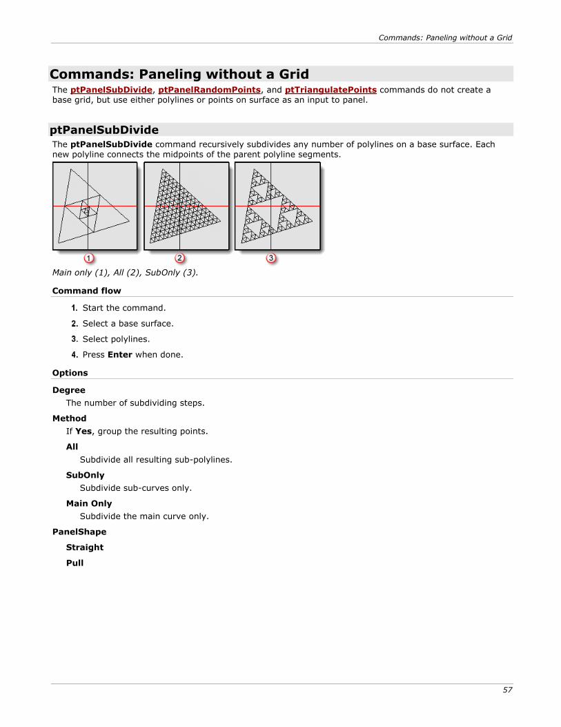
The ptPanelSubDivide command recursively subdivides any number of polylines on a base surface. Each new polyline connects the midpoints of the parent polyline segments.
Main only (1), All (2), SubOnly (3).
Command flow
Start the command.
Select a base surface.
Select polylines.
Press Enter when done.
Options
Degree
The number of subdividing steps.
Method
If Yes, group the resulting points.
All
Subdivide all resulting sub-polylines.
SubOnly
Subdivide sub-curves only.
Main Only
Subdivide the main curve only.
PanelShape
Straight
Pull
Commands: Paneling without a Grid
58
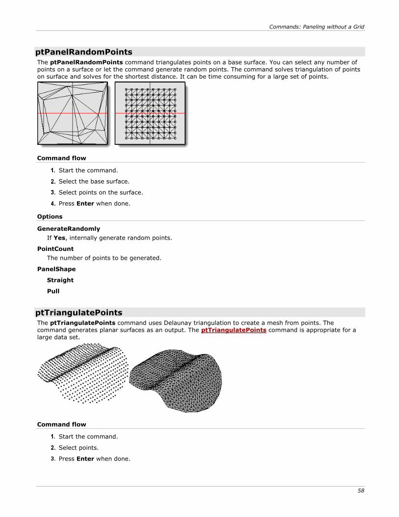
ptPanelRandomPoints
The ptPanelRandomPoints command triangulates points on a base surface. You can select any number of points on a surface or let the command generate random points. The command solves triangulation of points on surface and solves for the shortest distance. It can be time consuming for a large set of points.
Command flow
Start the command.
Select the base surface.
Select points on the surface.
Press Enter when done.
Options
GenerateRandomly
If Yes, internally generate random points.
PointCount
The number of points to be generated.
PanelShape
Straight
Pull
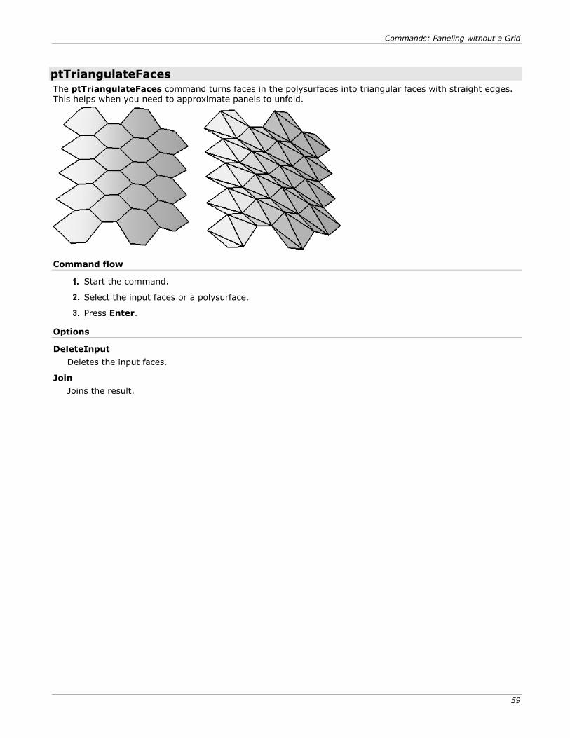
ptTriangulatePoints
The ptTriangulatePoints command uses Delaunay triangulation to create a mesh from points. The command generates planar surfaces as an output. The ptTriangulatePoints command is appropriate for a
large data set.
Command flow
Start the command.
Select points.
Press Enter when done.
Commands: Paneling without a Grid
59
ptTriangulateFaces
The ptTriangulateFaces command turns faces in the polysurfaces into triangular faces with straight edges. This helps when you need to approximate panels to unfold.
Command flow
Start the command.
Select the input faces or a polysurface.
Press Enter.
Options
DeleteInput
Deletes the input faces.
Join
Joins the result.
Commands: Grid Utilities
61
Commands: Grid Utilities The paneling grid can be modified directly using Rhino commands to project a grid on a surface, pull back, delete parts of it, or transform it such as Move, Scale, Rotate, SoftMove. In general, any modification that does not change names of the grid of points is acceptable. Utility commands ptDirection, ptRowsDirection, ptCompactGrid, ptCloseGrid, ptGridSeam, ptCleanOverlap, ptTrimGrid, ptOffsetPoints, ptChangeGridDensity, ptExtendGrid, and ptShiftGrid help manipulate the paneling grid.
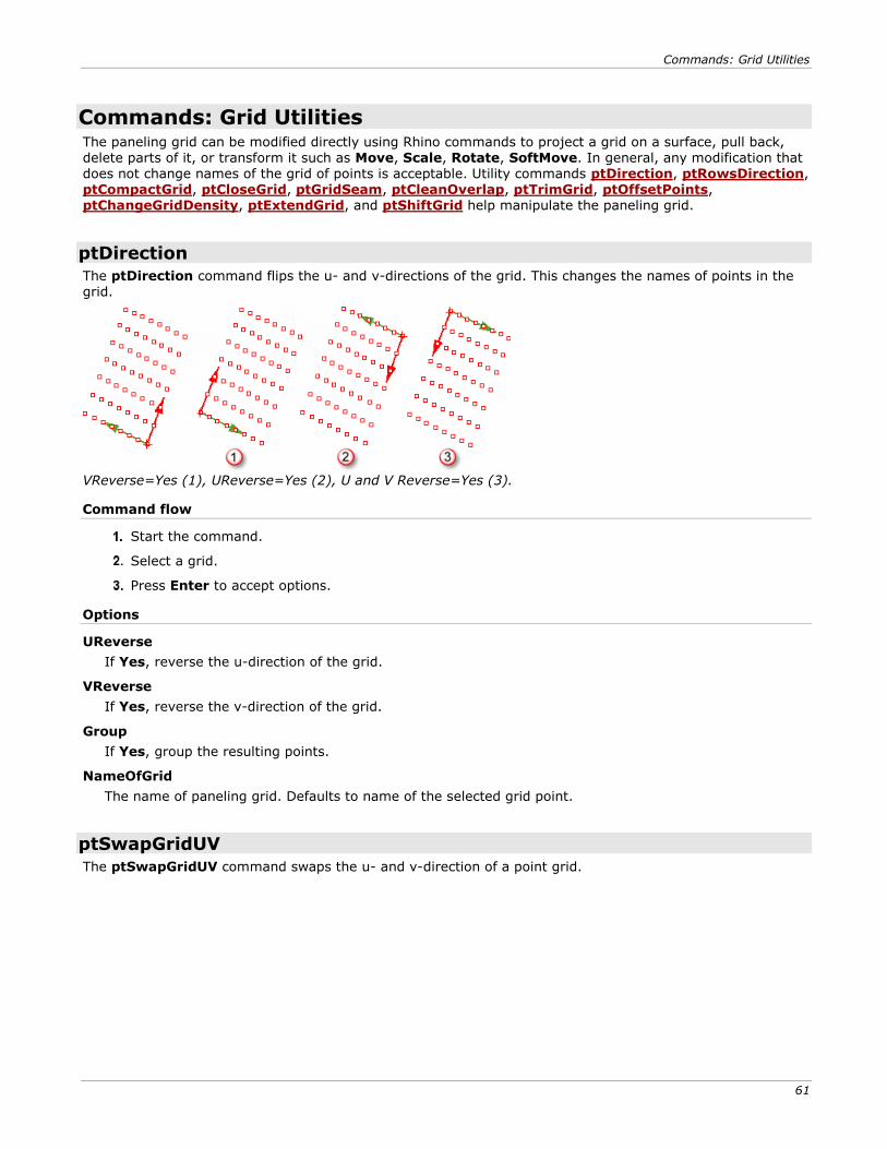
ptDirection
The ptDirection command flips the u- and v-directions of the grid. This changes the names of points in the grid.
VReverse=Yes (1), UReverse=Yes (2), U and V Reverse=Yes (3).
Command flow
Start the command.
Select a grid.
Press Enter to accept options.
Options
UReverse
If Yes, reverse the u-direction of the grid.
VReverse
If Yes, reverse the v-direction of the grid.
Group
If Yes, group the resulting points.
NameOfGrid
The name of paneling grid. Defaults to name of the selected grid point.
ptSwapGridUV
The ptSwapGridUV command swaps the u- and v-direction of a point grid.
Commands: Grid Utilities
62
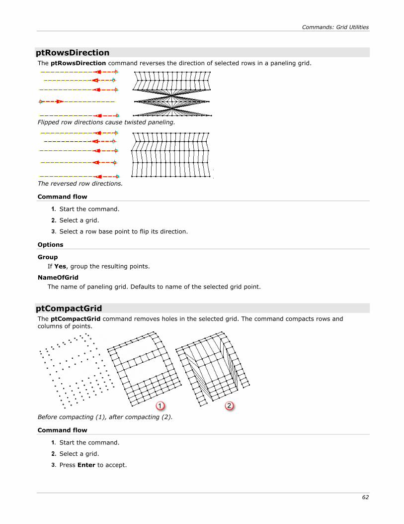
ptRowsDirection
The ptRowsDirection command reverses the direction of selected rows in a paneling grid.
Flipped row directions cause twisted paneling.
The reversed row directions.
Command flow
Start the command.
Select a grid.
Select a row base point to flip its direction.
Options
Group
If Yes, group the resulting points.
NameOfGrid
The name of paneling grid. Defaults to name of the selected grid point.
ptCompactGrid
The ptCompactGrid command removes holes in the selected grid. The command compacts rows and
columns of points.
Before compacting (1), after compacting (2).
Command flow
Start the command.
Select a grid.
Press Enter to accept.
Commands: Grid Utilities
63
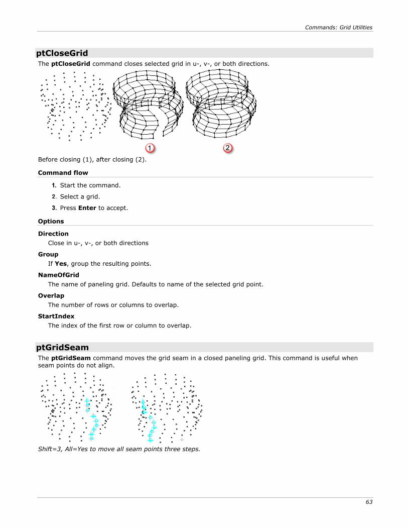
ptCloseGrid
The ptCloseGrid command closes selected grid in u-, v-, or both directions.
Before closing (1), after closing (2).
Command flow
Start the command.
Select a grid.
Press Enter to accept.
Options
Direction
Close in u-, v-, or both directions
Group
If Yes, group the resulting points.
NameOfGrid
The name of paneling grid. Defaults to name of the selected grid point.
Overlap
The number of rows or columns to overlap.
StartIndex
The index of the first row or column to overlap.
ptGridSeam
The ptGridSeam command moves the grid seam in a closed paneling grid. This command is useful when seam points do not align.
Shift=3, All=Yes to move all seam points three steps.
Commands: Grid Utilities
64
Command flow
Start the command.
Select a grid.
Select seam points to shift.
Press Enter when done
Options
Direction (U/V)
Appears when the grid is closed in two directions.
Shift
Represents the number of steps a selected seam point moves by. It can be a positive or negative number.
All
Moves all seam points together.
Group
If Yes, group the resulting points.
NameOfGrid
The name of paneling grid. Defaults to name of the selected grid point.
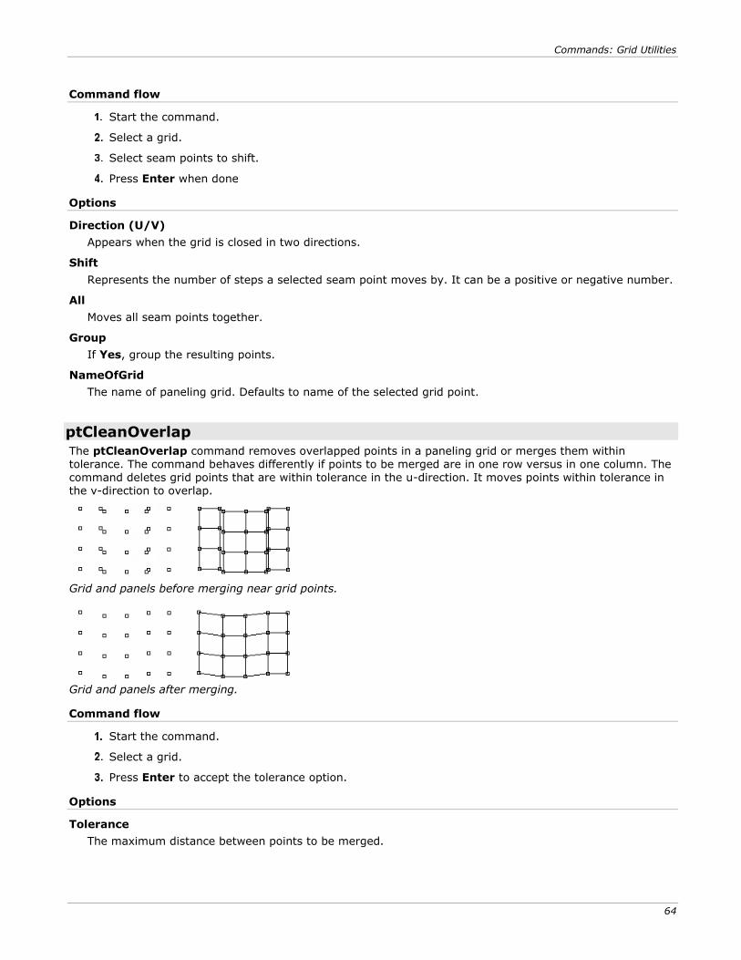
ptCleanOverlap
The ptCleanOverlap command removes overlapped points in a paneling grid or merges them within tolerance. The command behaves differently if points to be merged are in one row versus in one column. The command deletes grid points that are within tolerance in the u-direction. It moves points within tolerance in the v-direction to overlap.
Grid and panels before merging near grid points.
Grid and panels after merging.
Command flow
Start the command.
Select a grid.
Press Enter to accept the tolerance option.
Options
Tolerance
The maximum distance between points to be merged.
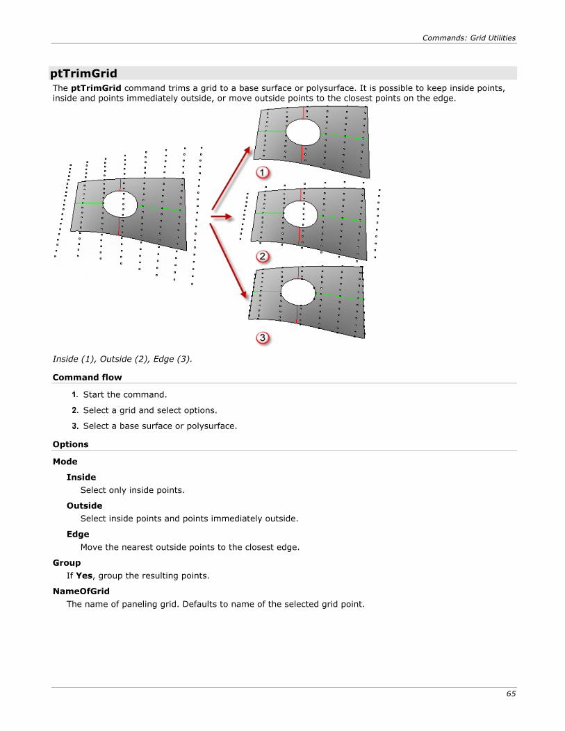
Commands: Grid Utilities
65
ptTrimGrid
The ptTrimGrid command trims a grid to a base surface or polysurface. It is possible to keep inside points, inside and points immediately outside, or move outside points to the closest points on the edge.
Inside (1), Outside (2), Edge (3).
Command flow
Start the command.
Select a grid and select options.
Select a base surface or polysurface.
Options
Mode
Inside
Select only inside points.
Outside
Select inside points and points immediately outside.
Edge
Move the nearest outside points to the closest edge.
Group
If Yes, group the resulting points.
NameOfGrid
The name of paneling grid. Defaults to name of the selected grid point.
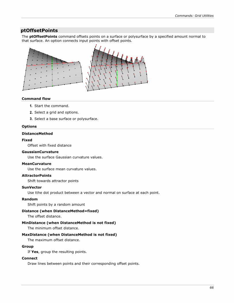
Commands: Grid Utilities
66
ptOffsetPoints
The ptOffsetPoints command offsets points on a surface or polysurface by a specified amount normal to that surface. An option connects input points with offset points.
Command flow
Start the command.
Select a grid and options.
Select a base surface or polysurface.
Options
DistanceMethod
Fixed
Offset with fixed distance
GaussianCurvature
Use the surface Gaussian curvature values.
MeanCurvature
Use the surface mean curvature values.
AttractorPoints
Shift towards attractor points
SunVector
Use tthe dot product between a vector and normal on surface at each point.
Random
Shift points by a random amount
Distance (when DistanceMethod=fixed)
The offset distance.
MinDistance (when DistanceMethod is not fixed)
The minimum offset distance.
MaxDistance (when DistanceMethod is not fixed)
The maximum offset distance.
Group
If Yes, group the resulting points.
Connect
Draw lines between points and their corresponding offset points.
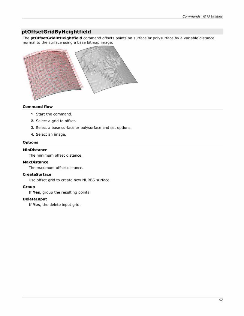
Commands: Grid Utilities
67
ptOffsetGridByHeightfield
The ptOffsetGridBtHeightfield command offsets points on surface or polysurface by a variable distance normal to the surface using a base bitmap image.
Command flow
Start the command.
Select a grid to offset.
Select a base surface or polysurface and set options.
Select an image.
Options
MinDistance
The minimum offset distance.
MaxDistance
The maximum offset distance.
CreateSurface
Use offset grid to create new NURBS surface.
Group
If Yes, group the resulting points.
DeleteInput
If Yes, the delete input grid.
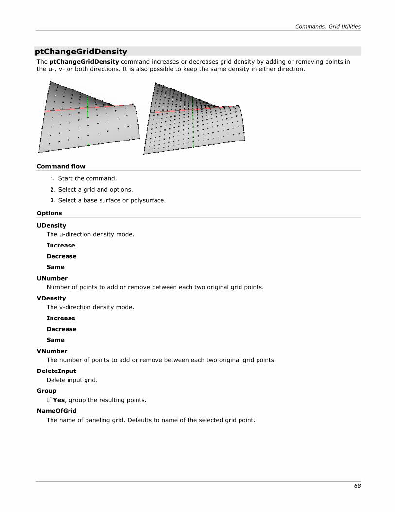
Commands: Grid Utilities
68
ptChangeGridDensity
The ptChangeGridDensity command increases or decreases grid density by adding or removing points in the u-, v- or both directions. It is also possible to keep the same density in either direction.
Command flow
Start the command.
Select a grid and options.
Select a base surface or polysurface.
Options
UDensity
The u-direction density mode.
Increase
Decrease
Same
UNumber
Number of points to add or remove between each two original grid points.
VDensity
The v-direction density mode.
Increase
Decrease
Same
VNumber
The number of points to add or remove between each two original grid points.
DeleteInput
Delete input grid.
Group
If Yes, group the resulting points.
NameOfGrid
The name of paneling grid. Defaults to name of the selected grid point.
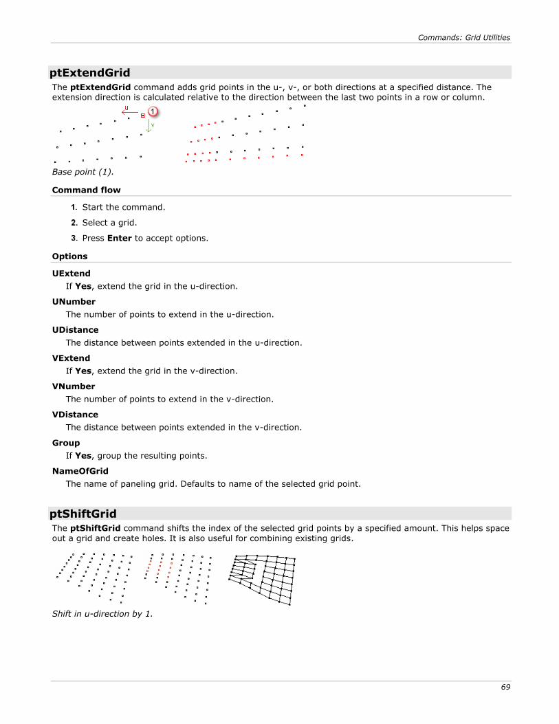
Commands: Grid Utilities
69
ptExtendGrid
The ptExtendGrid command adds grid points in the u-, v-, or both directions at a specified distance. The extension direction is calculated relative to the direction between the last two points in a row or column.
Base point (1).
Command flow
Start the command.
Select a grid.
Press Enter to accept options.
Options
UExtend
If Yes, extend the grid in the u-direction.
UNumber
The number of points to extend in the u-direction.
UDistance
The distance between points extended in the u-direction.
VExtend
If Yes, extend the grid in the v-direction.
VNumber
The number of points to extend in the v-direction.
VDistance
The distance between points extended in the v-direction.
Group
If Yes, group the resulting points.
NameOfGrid
The name of paneling grid. Defaults to name of the selected grid point.
ptShiftGrid
The ptShiftGrid command shifts the index of the selected grid points by a specified amount. This helps space
out a grid and create holes. It is also useful for combining existing grids.
Shift in u-direction by 1.
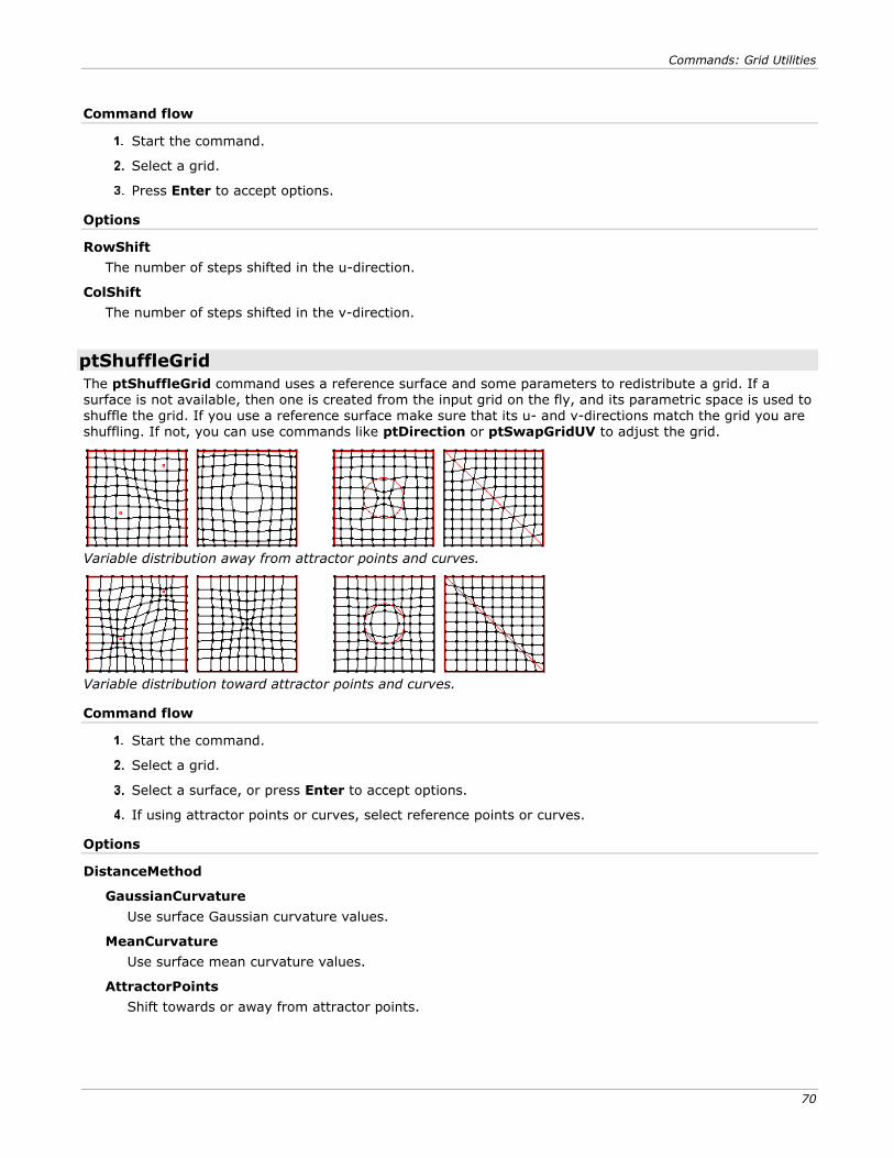
Commands: Grid Utilities
70
Command flow
Start the command.
Select a grid.
Press Enter to accept options.
Options
RowShift
The number of steps shifted in the u-direction.
ColShift
The number of steps shifted in the v-direction.
ptShuffleGrid
The ptShuffleGrid command uses a reference surface and some parameters to redistribute a grid. If a surface is not available, then one is created from the input grid on the fly, and its parametric space is used to shuffle the grid. If you use a reference surface make sure that its u- and v-directions match the grid you are shuffling. If not, you can use commands like ptDirection or ptSwapGridUV to adjust the grid.
Variable distribution away from attractor points and curves.
Variable distribution toward attractor points and curves.
Command flow
Start the command.
Select a grid.
Select a surface, or press Enter to accept options.
If using attractor points or curves, select reference points or curves.
Options
DistanceMethod
GaussianCurvature
Use surface Gaussian curvature values.
MeanCurvature
Use surface mean curvature values.
AttractorPoints
Shift towards or away from attractor points.
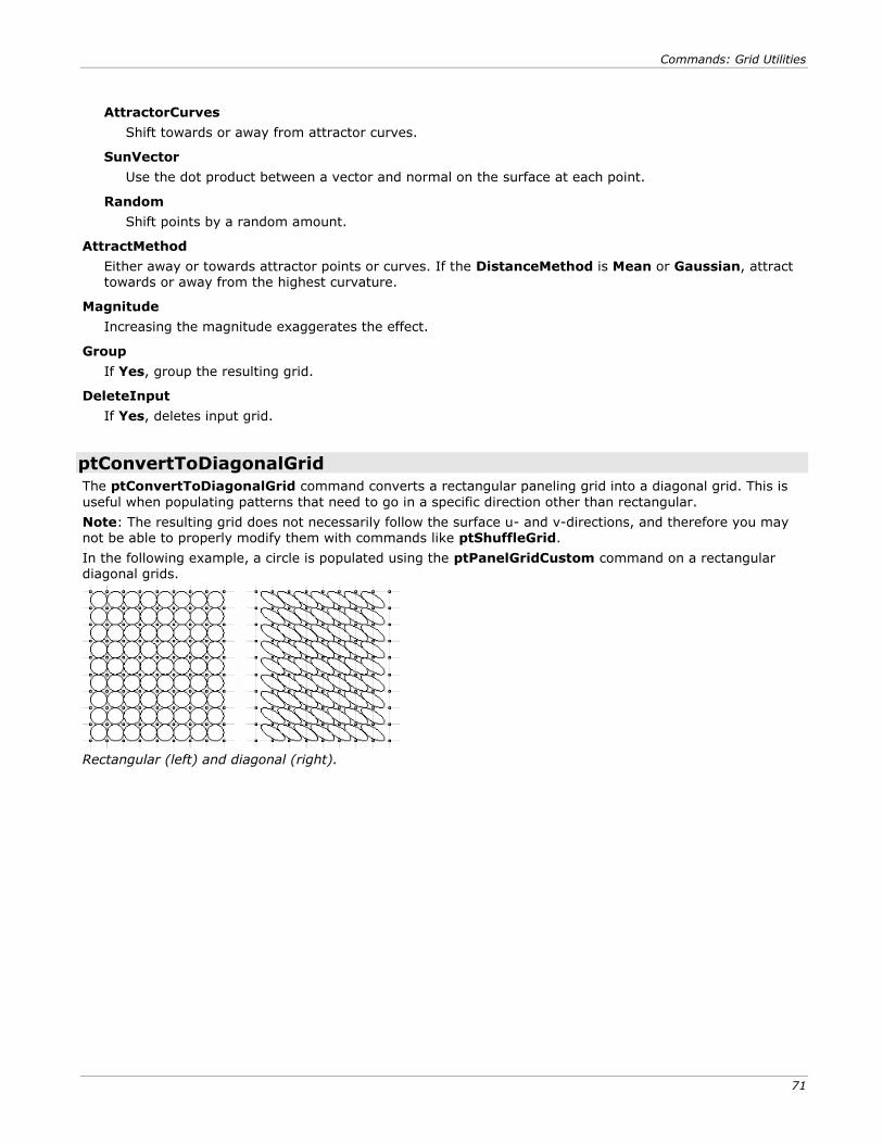
Commands: Grid Utilities
71
AttractorCurves
Shift towards or away from attractor curves.
SunVector
Use the dot product between a vector and normal on the surface at each point.
Random
Shift points by a random amount.
AttractMethod
Either away or towards attractor points or curves. If the DistanceMethod is Mean or Gaussian, attract towards or away from the highest curvature.
Magnitude
Increasing the magnitude exaggerates the effect.
Group
If Yes, group the resulting grid.
DeleteInput
If Yes, deletes input grid.
ptConvertToDiagonalGrid
The ptConvertToDiagonalGrid command converts a rectangular paneling grid into a diagonal grid. This is
useful when populating patterns that need to go in a specific direction other than rectangular.
Note: The resulting grid does not necessarily follow the surface u- and v-directions, and therefore you may not be able to properly modify them with commands like ptShuffleGrid.
In the following example, a circle is populated using the ptPanelGridCustom command on a rectangular diagonal grids.
Rectangular (left) and diagonal (right).
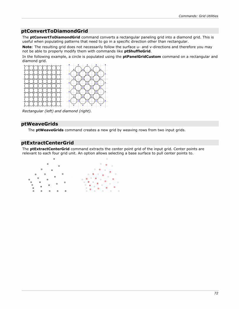
Commands: Grid Utilities
72
ptConvertToDiamondGrid
The ptConvertToDiamondGrid command converts a rectangular paneling grid into a diamond grid. This is useful when populating patterns that need to go in a specific direction other than rectangular.
Note: The resulting grid does not necessarily follow the surface u- and v-directions and therefore you may not be able to properly modify them with commands like ptShuffleGrid.
In the following example, a circle is populated using the ptPanelGridCustom command on a rectangular and diamond grid.
Rectangular (left) and diamond (right).
ptWeaveGrids
The ptWeaveGrids command creates a new grid by weaving rows from two input grids.
ptExtractCenterGrid
The ptExtractCenterGrid command extracts the center point grid of the input grid. Center points are relevant to each four grid unit. An option allows selecting a base surface to pull center points to.
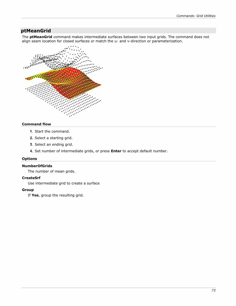
Commands: Grid Utilities
73
ptMeanGrid
The ptMeanGrid command makes intermediate surfaces between two input grids. The command does not align seam location for closed surfaces or match the u- and v-direction or parameterization.
Command flow
Start the command.
Select a starting grid.
Select an ending grid.
Set number of intermediate grids, or press Enter to accept default number.
Options
NumberOfGrids
The number of mean grids.
CreateSrf
Use intermediate grid to create a surface
Group
If Yes, group the resulting grid.
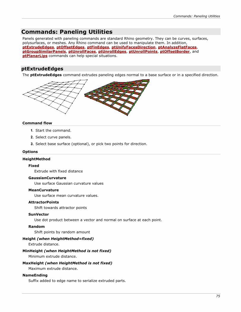
Commands: Paneling Utilities
75
Commands: Paneling Utilities Panels generated with paneling commands are standard Rhino geometry. They can be curves, surfaces, polysurfaces, or meshes. Any Rhino command can be used to manipulate them. In addition, ptExtrudeEdges, ptOffsetEdges, ptFinEdges, ptUnifyFacesDirection, ptAnalyzeFlatFaces, ptGroupSimilarPanels, ptUnrollFaces, ptUnrollEdges, ptUnrollPoints, ptOffsetBorder, and ptPlanarLips commands can help special situations.
ptExtrudeEdges
The ptExtrudeEdges command extrudes paneling edges normal to a base surface or in a specified direction.
Command flow
Start the command.
Select curve panels.
Select base surface (optional), or pick two points for direction.
Options
HeightMethod
Fixed
Extrude with fixed distance
GaussianCurvature
Use surface Gaussian curvature values
MeanCurvature
Use surface mean curvature values.
AttractorPoints
Shift towards attractor points
SunVector
Use dot product between a vector and normal on surface at each point.
Random
Shift points by random amount
Height (when HeightMethod=fixed)
Extrude distance.
MinHeight (when HeightMethod is not fixed)
Minimum extrude distance.
MaxHeight (when HeightMethod is not fixed)
Maximum extrude distance.
NameEnding
Suffix added to edge name to serialize extruded parts.
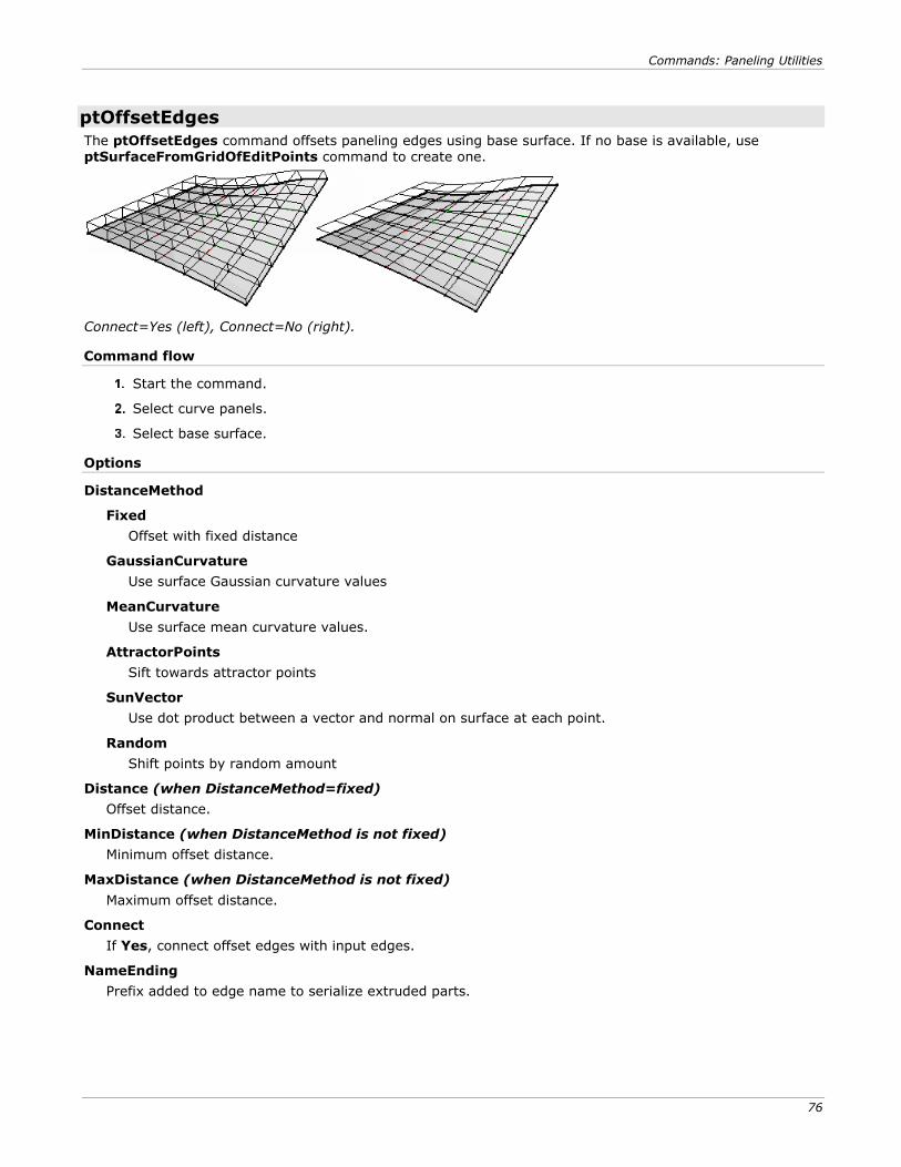
Commands: Paneling Utilities
76
ptOffsetEdges
The ptOffsetEdges command offsets paneling edges using base surface. If no base is available, use ptSurfaceFromGridOfEditPoints command to create one.
Connect=Yes (left), Connect=No (right).
Command flow
Start the command.
Select curve panels.
Select base surface.
Options
DistanceMethod
Fixed
Offset with fixed distance
GaussianCurvature
Use surface Gaussian curvature values
MeanCurvature
Use surface mean curvature values.
AttractorPoints
Sift towards attractor points
SunVector
Use dot product between a vector and normal on surface at each point.
Random
Shift points by random amount
Distance (when DistanceMethod=fixed)
Offset distance.
MinDistance (when DistanceMethod is not fixed)
Minimum offset distance.
MaxDistance (when DistanceMethod is not fixed)
Maximum offset distance.
Connect
If Yes, connect offset edges with input edges.
NameEnding
Prefix added to edge name to serialize extruded parts.
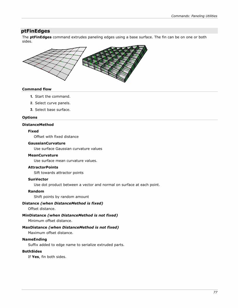
Commands: Paneling Utilities
77
ptFinEdges
The ptFinEdges command extrudes paneling edges using a base surface. The fin can be on one or both sides.
Command flow
Start the command.
Select curve panels.
Select base surface.
Options
DistanceMethod
Fixed
Offset with fixed distance
GaussianCurvature
Use surface Gaussian curvature values
MeanCurvature
Use surface mean curvature values.
AttractorPoints
Sift towards attractor points
SunVector
Use dot product between a vector and normal on surface at each point.
Random
Shift points by random amount
Distance (when DistanceMethod is fixed)
Offset distance.
MinDistance (when DistanceMethod is not fixed)
Minimum offset distance.
MaxDistance (when DistanceMethod is not fixed)
Maximum offset distance.
NameEnding
Suffix added to edge name to serialize extruded parts.
BothSides
If Yes, fin both sides.
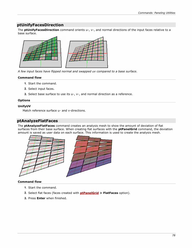
Commands: Paneling Utilities
78
ptUnifyFacesDirection
The ptUnifyFacesDirection command orients u-, v-, and normal directions of the input faces relative to a base surface.
A few input faces have flipped normal and swapped uv compared to a base surface.
Command flow
Start the command.
Select input faces.
Select base surface to use its u-, v-, and normal direction as a reference.
Options
UnifyUV
Match reference surface u- and v-directions.
ptAnalyzeFlatFaces
The ptAnalyzeFlatFaces command creates an analysis mesh to show the amount of deviation of flat surfaces from their base surface. When creating flat surfaces with the ptPanelGrid command, the deviation
amount is saved as user data on each surface. This information is used to create the analysis mesh.
Command flow
Start the command.
Select flat faces (faces created with ptPanelGrid > FlatFaces option).
Press Enter when finished.
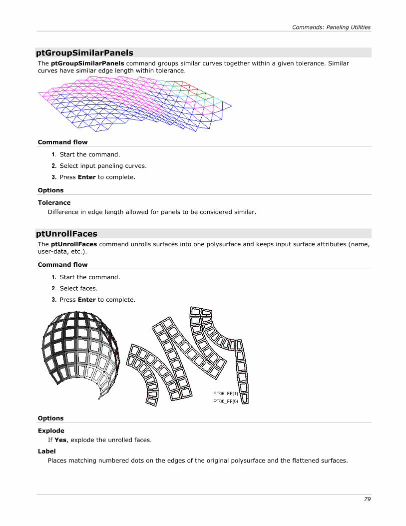
Commands: Paneling Utilities
79
ptGroupSimilarPanels
The ptGroupSimilarPanels command groups similar curves together within a given tolerance. Similar curves have similar edge length within tolerance.
Command flow
Start the command.
Select input paneling curves.
Press Enter to complete.
Options
Tolerance
Difference in edge length allowed for panels to be considered similar.
ptUnrollFaces
The ptUnrollFaces command unrolls surfaces into one polysurface and keeps input surface attributes (name, user-data, etc.).
Command flow
Start the command.
Select faces.
Press Enter to complete.
Options
Explode
If Yes, explode the unrolled faces.
Label
Places matching numbered dots on the edges of the original polysurface and the flattened surfaces.
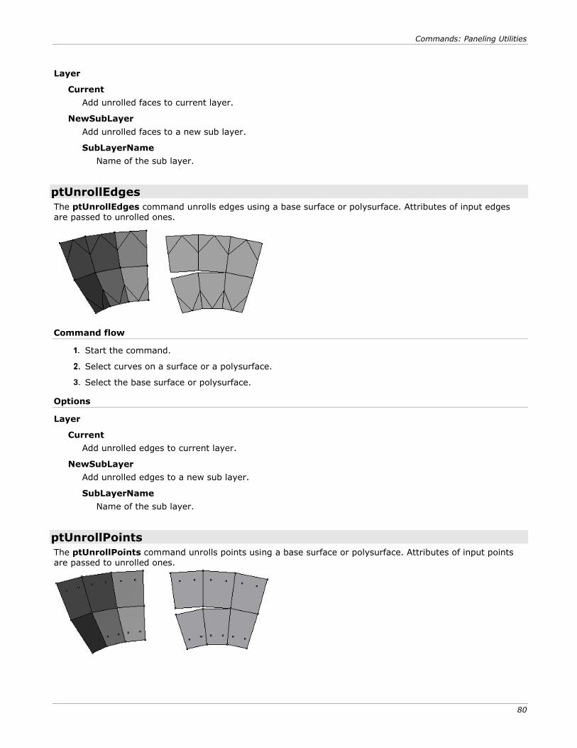
Commands: Paneling Utilities
80
Layer
Current
Add unrolled faces to current layer.
NewSubLayer
Add unrolled faces to a new sub layer.
SubLayerName
Name of the sub layer.
ptUnrollEdges
The ptUnrollEdges command unrolls edges using a base surface or polysurface. Attributes of input edges are passed to unrolled ones.
Command flow
Start the command.
Select curves on a surface or a polysurface.
Select the base surface or polysurface.
Options
Layer
Current
Add unrolled edges to current layer.
NewSubLayer
Add unrolled edges to a new sub layer.
SubLayerName
Name of the sub layer.
ptUnrollPoints
The ptUnrollPoints command unrolls points using a base surface or polysurface. Attributes of input points are passed to unrolled ones.
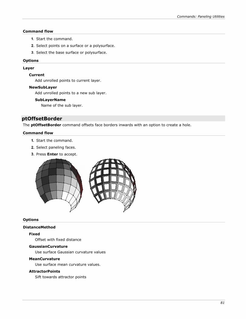
Commands: Paneling Utilities
81
Command flow
Start the command.
Select points on a surface or a polysurface.
Select the base surface or polysurface.
Options
Layer
Current
Add unrolled points to current layer.
NewSubLayer
Add unrolled points to a new sub layer.
SubLayerName
Name of the sub layer.
ptOffsetBorder
The ptOffsetBorder command offsets face borders inwards with an option to create a hole.
Command flow
Start the command.
Select paneling faces.
Press Enter to accept.
Options
DistanceMethod
Fixed
Offset with fixed distance
GaussianCurvature
Use surface Gaussian curvature values
MeanCurvature
Use surface mean curvature values.
AttractorPoints
Sift towards attractor points
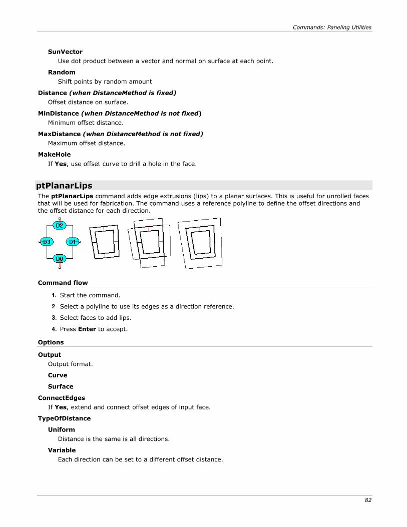
Commands: Paneling Utilities
82
SunVector
Use dot product between a vector and normal on surface at each point.
Random
Shift points by random amount
Distance (when DistanceMethod is fixed)
Offset distance on surface.
MinDistance (when DistanceMethod is not fixed)
Minimum offset distance.
MaxDistance (when DistanceMethod is not fixed)
Maximum offset distance.
MakeHole
If Yes, use offset curve to drill a hole in the face.
ptPlanarLips
The ptPlanarLips command adds edge extrusions (lips) to a planar surfaces. This is useful for unrolled faces that will be used for fabrication. The command uses a reference polyline to define the offset directions and the offset distance for each direction.
Command flow
Start the command.
Select a polyline to use its edges as a direction reference.
Select faces to add lips.
Press Enter to accept.
Options
Output
Output format.
Curve
Surface
ConnectEdges
If Yes, extend and connect offset edges of input face.
TypeOfDistance
Uniform
Distance is the same is all directions.
Variable
Each direction can be set to a different offset distance.
Commands: Paneling Utilities
83
DeleteInput
If Yes, delete input faces.
Distance
Offset distance. If TypeOfDistance=Variable, each tagged edge will have a separate distance value to
set (D1, D2, etc.)
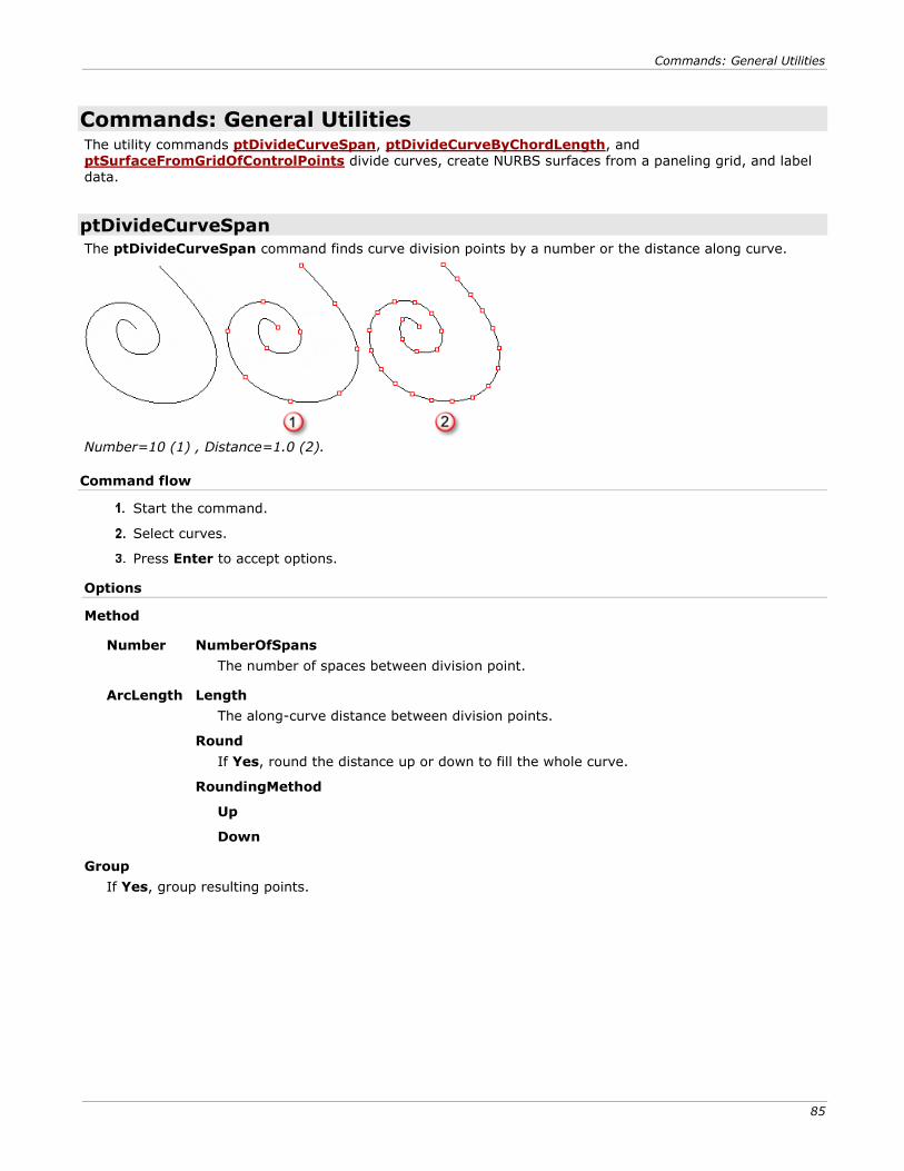
Commands: General Utilities
85
Commands: General Utilities The utility commands ptDivideCurveSpan, ptDivideCurveByChordLength, and ptSurfaceFromGridOfControlPoints divide curves, create NURBS surfaces from a paneling grid, and label data.
ptDivideCurveSpan
The ptDivideCurveSpan command finds curve division points by a number or the distance along curve.
Number=10 (1) , Distance=1.0 (2).
Command flow
Start the command.
Select curves.
Press Enter to accept options.
Options
Method
Number NumberOfSpans
The number of spaces between division point.
ArcLength Length
The along-curve distance between division points.
Round
If Yes, round the distance up or down to fill the whole curve.
RoundingMethod
Up
Down
Group
If Yes, group resulting points.
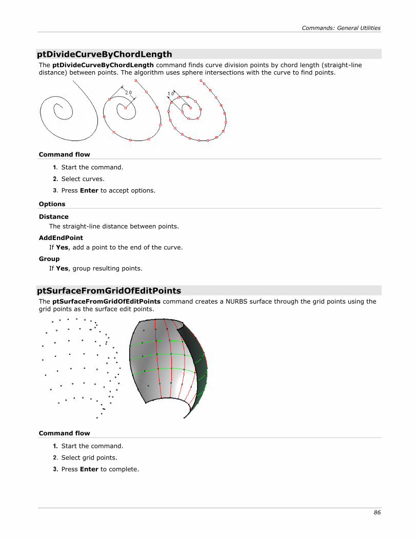
Commands: General Utilities
86
ptDivideCurveByChordLength
The ptDivideCurveByChordLength command finds curve division points by chord length (straight-line distance) between points. The algorithm uses sphere intersections with the curve to find points.
Command flow
Start the command.
Select curves.
Press Enter to accept options.
Options
Distance
The straight-line distance between points.
AddEndPoint
If Yes, add a point to the end of the curve.
Group
If Yes, group resulting points.
ptSurfaceFromGridOfEditPoints
The ptSurfaceFromGridOfEditPoints command creates a NURBS surface through the grid points using the
grid points as the surface edit points.
Command flow
Start the command.
Select grid points.
Press Enter to complete.
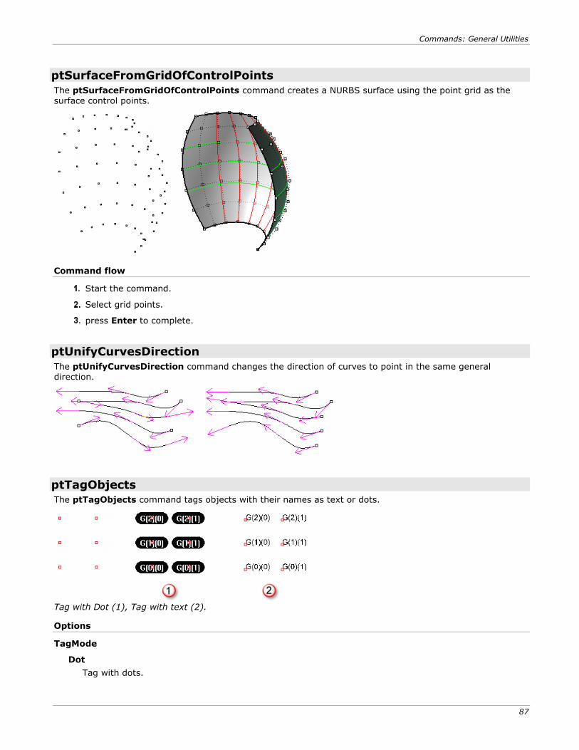
Commands: General Utilities
87
ptSurfaceFromGridOfControlPoints
The ptSurfaceFromGridOfControlPoints command creates a NURBS surface using the point grid as the surface control points.
Command flow
Start the command.
Select grid points.
press Enter to complete.
ptUnifyCurvesDirection
The ptUnifyCurvesDirection command changes the direction of curves to point in the same general direction.
ptTagObjects
The ptTagObjects command tags objects with their names as text or dots.
Tag with Dot (1), Tag with text (2).
Options
TagMode
Dot
Tag with dots.
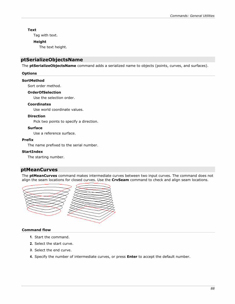
Commands: General Utilities
88
Text
Tag with text.
Height
The text height.
ptSerializeObjectsName
The ptSerializeObjectsName command adds a serialized name to objects (points, curves, and surfaces).
Options
SortMethod
Sort order method.
OrderOfSelection
Use the selection order.
Coordinates
Use world coordinate values.
Direction
Pick two points to specify a direction.
Surface
Use a reference surface.
Prefix
The name prefixed to the serial number.
StartIndex
The starting number.
ptMeanCurves
The ptMeanCurves command makes intermediate curves between two input curves. The command does not align the seam locations for closed curves. Use the CrvSeam command to check and align seam locations.
Command flow
Start the command.
Select the start curve.
Select the end curve.
Specify the number of intermediate curves, or press Enter to accept the default number.
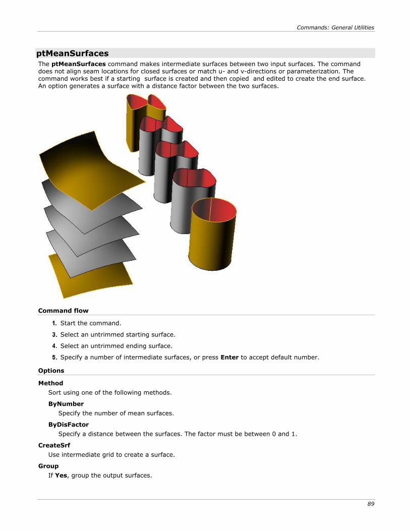
Commands: General Utilities
89
ptMeanSurfaces
The ptMeanSurfaces command makes intermediate surfaces between two input surfaces. The command does not align seam locations for closed surfaces or match u- and v-directions or parameterization. The command works best if a starting surface is created and then copied and edited to create the end surface. An option generates a surface with a distance factor between the two surfaces.
Command flow
Start the command.
Select an untrimmed starting surface.
Select an untrimmed ending surface.
Specify a number of intermediate surfaces, or press Enter to accept default number.
Options
Method
Sort using one of the following methods.
ByNumber
Specify the number of mean surfaces.
ByDisFactor
Specify a distance between the surfaces. The factor must be between 0 and 1.
CreateSrf
Use intermediate grid to create a surface.
Group
If Yes, group the output surfaces.
Commands: General Utilities
90
ptRemoveOverlappedPoints
The ptRemoveOverlappedPoints command is a cleaning function that removes overlapped points. It can be used before calling one of the serialize commands to avoid duplicates.
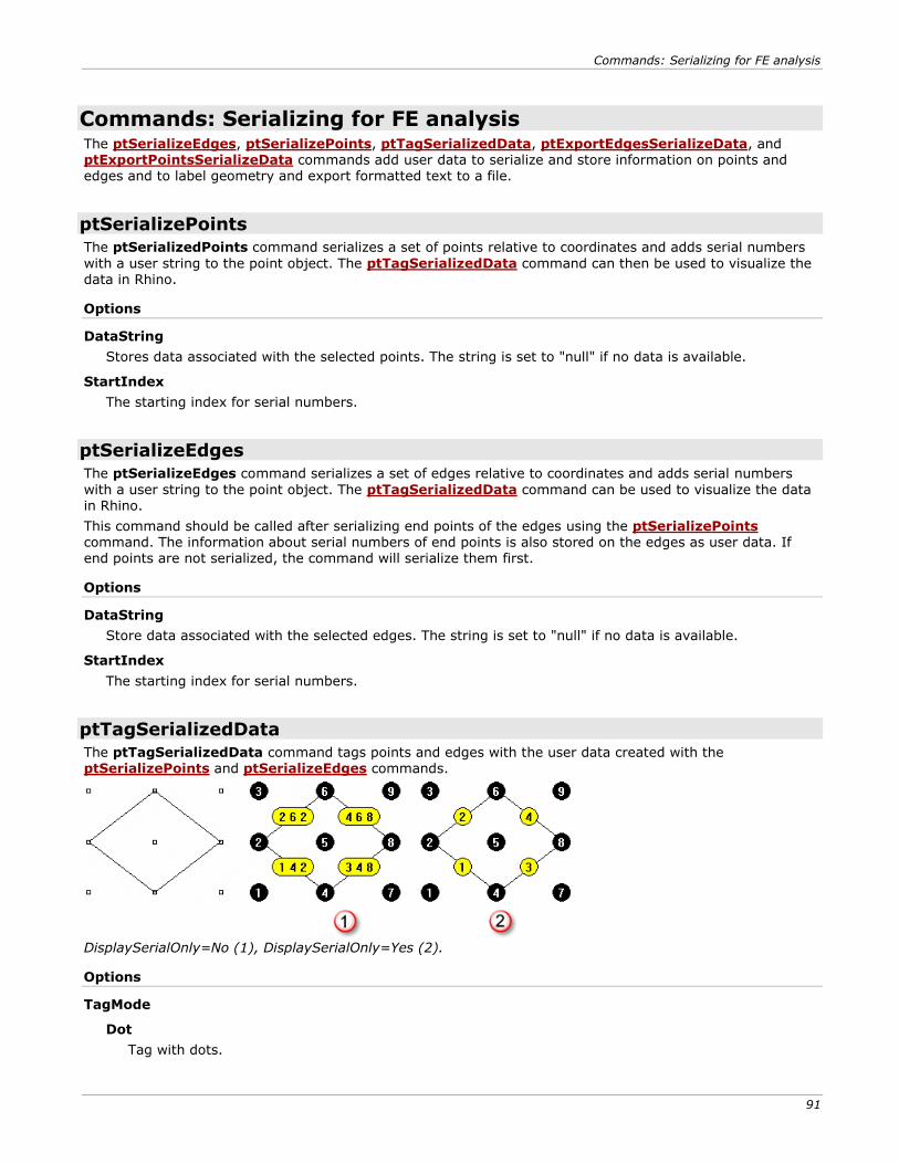
Commands: Serializing for FE analysis
91
Commands: Serializing for FE analysis The ptSerializeEdges, ptSerializePoints, ptTagSerializedData, ptExportEdgesSerializeData, and ptExportPointsSerializeData commands add user data to serialize and store information on points and edges and to label geometry and export formatted text to a file.
ptSerializePoints
The ptSerializedPoints command serializes a set of points relative to coordinates and adds serial numbers
with a user string to the point object. The ptTagSerializedData command can then be used to visualize the data in Rhino.
Options
DataString
Stores data associated with the selected points. The string is set to "null" if no data is available.
StartIndex
The starting index for serial numbers.
ptSerializeEdges
The ptSerializeEdges command serializes a set of edges relative to coordinates and adds serial numbers
with a user string to the point object. The ptTagSerializedData command can be used to visualize the data in Rhino.
This command should be called after serializing end points of the edges using the ptSerializePoints command. The information about serial numbers of end points is also stored on the edges as user data. If end points are not serialized, the command will serialize them first.
Options
DataString
Store data associated with the selected edges. The string is set to "null" if no data is available.
StartIndex
The starting index for serial numbers.
ptTagSerializedData
The ptTagSerializedData command tags points and edges with the user data created with the ptSerializePoints and ptSerializeEdges commands.
DisplaySerialOnly=No (1), DisplaySerialOnly=Yes (2).
Options
TagMode
Dot
Tag with dots.
Commands: Serializing for FE analysis
92
Text
Tag with text.
Height
The text height.
DisplaySerialOnly
If Yes, ignores the edge end point serial numbers and the point and edge data strings.
ptExportPointsSerializeData
The ptExportPointsSerializeData command creates a text file with serialized data created with the ptSerializePoints command.
Command flow
Start the command.
Select points and select options.
Specify a target file
Options
AddPointsCoordinates
Output points coordinates (x, y and z).
Description
Specify a title for the file. This is set to "null" if none is available.
StartString
The prefix string to be added before each point datum.
EndString
The suffix string to be added after each point datum.
NewLine
If Yes, separate points output by a new line.
PrintPointSerial
If No, the serial number will not display.
Append
Append the data to an existing file.
SetTargetFile
Specify the file.
Commands: Serializing for FE analysis
93
ptExportEdgesSerializeData
The ptExportEdgesSerializeData command creates a text file with serialize data created with the ptSerializeEdges command.
Command flow
Start the command.
Select points and set options.
Set target file.
Options
Description
Specify a title for the file. This is set to "null" if none is available.
StartString
The prefix string to be added before each edge datum.
EndString
The prefix string to be added before each edge datum.
NewLine
If Yes, separate edges output by a new line.
PrintEdgeSerial
If No, the serial number will not display.
Append
Append to an existing file.
SetTargetFile
Specify the file.
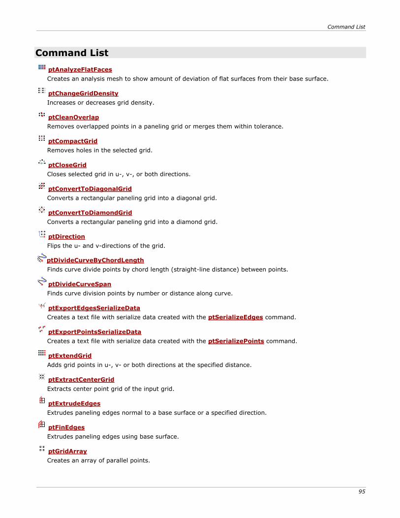
Command List
95
Command List
ptAnalyzeFlatFaces
Creates an analysis mesh to show amount of deviation of flat surfaces from their base surface.
ptChangeGridDensity
Increases or decreases grid density.
ptCleanOverlap
Removes overlapped points in a paneling grid or merges them within tolerance.
ptCompactGrid
Removes holes in the selected grid.
ptCloseGrid
Closes selected grid in u-, v-, or both directions.
ptConvertToDiagonalGrid
Converts a rectangular paneling grid into a diagonal grid.
ptConvertToDiamondGrid
Converts a rectangular paneling grid into a diamond grid.
ptDirection
Flips the u- and v-directions of the grid.
ptDivideCurveByChordLength
Finds curve divide points by chord length (straight-line distance) between points.
ptDivideCurveSpan
Finds curve division points by number or distance along curve.
ptExportEdgesSerializeData
Creates a text file with serialize data created with the ptSerializeEdges command.
ptExportPointsSerializeData
Creates a text file with serialize data created with the ptSerializePoints command.
ptExtendGrid
Adds grid points in u-, v- or both directions at the specified distance.
ptExtractCenterGrid
Extracts center point grid of the input grid.
ptExtrudeEdges
Extrudes paneling edges normal to a base surface or a specified direction.
ptFinEdges
Extrudes paneling edges using base surface.
ptGridArray
Creates an array of parallel points.
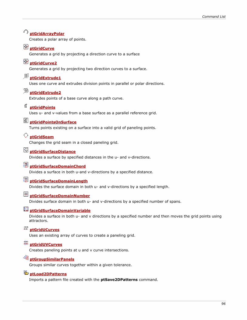
Command List
96
ptGridArrayPolar
Creates a polar array of points.
ptGridCurve
Generates a grid by projecting a direction curve to a surface
ptGridCurve2
Generates a grid by projecting two direction curves to a surface.
ptGridExtrude1
Uses one curve and extrudes division points in parallel or polar directions.
ptGridExtrude2
Extrudes points of a base curve along a path curve.
ptGridPoints
Uses u- and v-values from a base surface as a parallel reference grid.
ptGridPointsOnSurface
Turns points existing on a surface into a valid grid of paneling points.
ptGridSeam
Changes the grid seam in a closed paneling grid.
ptGridSurfaceDistance
Divides a surface by specified distances in the u- and v-directions.
ptGridSurfaceDomainChord
Divides a surface in both u-and v-directions by a specified distance.
ptGridSurfaceDomainLength
Divides the surface domain in both u- and v-directions by a specified length.
ptGridSurfaceDomainNumber
Divides surface domain in both u- and v-directions by a specified number of spans.
ptGridSurfaceDomainVariable
Divides a surface in both u- and v directions by a specified number and then moves the grid points using attractors.
ptGridUCurves
Uses an existing array of curves to create a paneling grid.
ptGridUVCurves
Creates paneling points at u and v curve intersections.
ptGroupSimilarPanels
Groups similar curves together within a given tolerance.
ptLoad2DPatterns
Imports a pattern file created with the ptSave2DPatterns command.
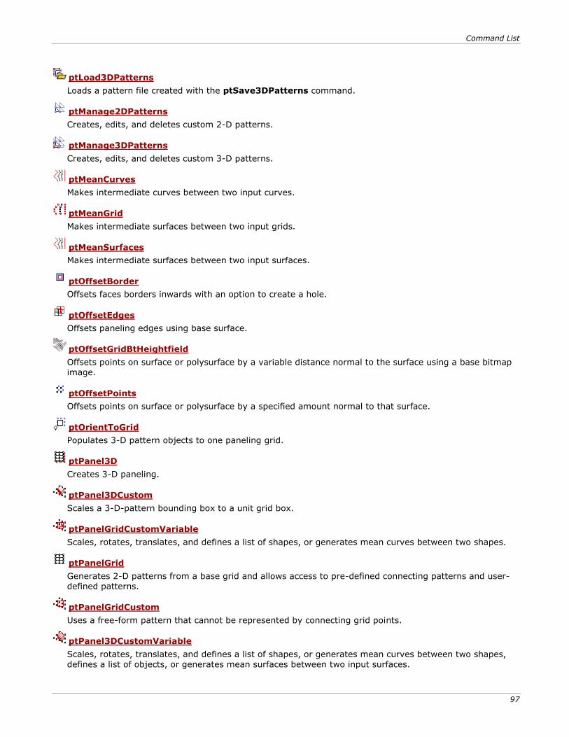
Command List
97
ptLoad3DPatterns
Loads a pattern file created with the ptSave3DPatterns command.
ptManage2DPatterns
Creates, edits, and deletes custom 2-D patterns.
ptManage3DPatterns
Creates, edits, and deletes custom 3-D patterns.
ptMeanCurves
Makes intermediate curves between two input curves.
ptMeanGrid
Makes intermediate surfaces between two input grids.
ptMeanSurfaces
Makes intermediate surfaces between two input surfaces.
ptOffsetBorder
Offsets faces borders inwards with an option to create a hole.
ptOffsetEdges
Offsets paneling edges using base surface.
ptOffsetGridBtHeightfield
Offsets points on surface or polysurface by a variable distance normal to the surface using a base bitmap image.
ptOffsetPoints
Offsets points on surface or polysurface by a specified amount normal to that surface.
ptOrientToGrid
Populates 3-D pattern objects to one paneling grid.
ptPanel3D
Creates 3-D paneling.
ptPanel3DCustom
Scales a 3-D-pattern bounding box to a unit grid box.
ptPanelGridCustomVariable
Scales, rotates, translates, and defines a list of shapes, or generates mean curves between two shapes.
ptPanelGrid
Generates 2-D patterns from a base grid and allows access to pre-defined connecting patterns and user-defined patterns.
ptPanelGridCustom
Uses a free-form pattern that cannot be represented by connecting grid points.
ptPanel3DCustomVariable
Scales, rotates, translates, and defines a list of shapes, or generates mean curves between two shapes, defines a list of objects, or generates mean surfaces between two input surfaces.
Command List
98
ptPanelGridQuads
Adjusts paneling grid to create maximum number of quadrangles within tolerance.
ptPanelRandomPoints
Triangulates points on a base surface. Select any number of points on surface or generates random points.
ptPanelSubDivide
Recursively subdivides any number of polylines on a base surface. Each new polyline connects the midpoints of parent polyline segments.
ptPlanarLips
Generates edge extrusions (lips) to planar surfaces.
ptRemoveOverlappedPoints
Removes overlapped points.
ptRowsDirection
Reverses the direction of selected rows in a paneling grid.
ptSave2DPatterns
Saves custom 2-D patterns
ptSave3DPatterns
Saves 3-D patterns.
ptSerializeEdges
Serializes a set of edges relative to coordinates and adds serial numbers with user string to the point
object.
ptSerializeObjectsName
Adds a serialized name to objects.
ptSerializePoints
Serializes a set of points relative to coordinates and adds serial numbers with a user string to the point object.
ptShiftGrid
Shifts the index of selected grid points by the specified amount.
ptShuffleGrid
Uses reference surface and some parameters to redistribute a given grid.
ptSurfaceFromGridOfControlPoints
Creates a NURBS surface using the point grid as surface control points.
ptSurfaceFromGridOfEditPoints
Creates a NURBS surface through the grid points using the grid points as surface edit points.
ptSwapGridUV
Swaps the u- and v-direction of a point grid.
Command List
99
ptTagObjects
Tags objects with their names as text or dots.
ptTagSerializedData
Tags objects (points and edges) with the user data created with the ptSerializePoints and ptSerializeEdges commands.
ptTriangulateFaces
Turns faces in the polysurfaces into triangular faces with straight edges.
ptTriangulatePoints
Uses Delaunay triangulation to create a mesh from points. The command generates planar surfaces as an output.
ptTrimGrid
Trims a grid to a base surface or polysurface.
ptUnifyCurvesDirection
Unifies the direction of curves to point in the same general direction.
ptUnifyFacesDirection
Orients u-, v-, and normal directions of the input faces relative to a base surface.
ptUnrollEdges
Unrolls edges using a base surface or polysurface.
ptUnrollFaces
Unrolls surfaces that do not have to be joined in one polysurface
ptUnrollPoints
Unrolls points using a base surface or polysurface.
ptWeaveGrids
Creates a new grid by weaving rows from two input grids.