table of contents - mcrae engineering · 16,000 20,500 20,500 35,500 48,000 63,000 cap. cfm 6 8 10...
TRANSCRIPT

These filters and filter-silencers are availablewith a variety of filter panels, each with itsown restriction characteristics. To reflect thatfact, the total pressure drop for a specific filterapplication is the sum of two pressure dropvalues:
1 The first value is the restriction that canbe attributed to the filter housing withoutfilter panels. This value is found in thegraphs at right.
2 The second value is the restrictionthrough the filter panel media. Thesevalues are taken from the table below.
The pressure drop values for the filter panelsare listed in the table as pressure drop ininches of water gauge at various flow ratesin CFM. The housing pressure drop isshown in graphical form as a function of airflow in CFM versus pressure drop in inchesof water gauge.
To avoid confusion, pressure drop values inthe graphs include pipe entrance pressuredrops from the atmospheric end of the inletpipe. These drops are significant,contributing as much as 75% of the totalpressure drop, and should not be attributedto the filter. Adding the filter transfers thesepressure losses to the interior of the filterhousing. A pressure drop measurement atthe pressure tap on the filter outlet reflectsthe total:
Pipe entrance lossVelocity pressureHousing restriction
Application GuideFilters and Filter-Silencers
500600700800900
1,0001,2501,500
0.010.020.030.030.040.050.080.12
W-2
0.060.080.110.140.170.210.310.44
DD-2
0.090.130.160.210.250.300.440.59
P-11
0.070.100.140.170.210.260.390.56
W-2and DD-2
0.100.150.190.240.290.350.520.71
W-2and P-11
0.800.961.121.281.441.602.002.40
P-8and P-12F
0.280.350.420.490.560.640.831.04
0.290.370.450.520.600.690.911.16
W-2and P-5
0.340.430.530.630.730.851.141.48
DD-2and P-5P-5CFM
per filter
Rota
ry P
ositi
ve
Blow
er S
ilenc
ers
8.1
Filte
rs a
nd
Filte
r-Si
lenc
ers
12
34
56
710
9
8.1
See
page
s 1.
1–1.
3 fo
r ord
erin
g in
form
atio
n |
ww
w.u
nive
rsal
sile
ncer
.com
8
Pressure Drop Values for 20" �� 25" Panel Filters, in Water Gauge
0.1
0.2
0.5
1.0
2.03.0
5.0
10.0Pressure Drop, in Inches Water Gauge
500 1K 2K 3K 5K 10K 20K 50K 100KFlow Rate, CFM
Pressure Drop Curves for Filter HousingsFH, FSH, BFH, and FASH Series
10"8" 12" 14" 18" 20" 24" 30" 36" 42" 48"16"
6" outlet nozzle size
0.1
0.2
0.5
1.02.0
3.0
5.0
10.0
Flow Rate, CFM
Pressure Drop, in Inches Water Gauge
Pressure Drop Curves for FilterFRH and FCRH Series
8-2 m
odel
10-2 10
-4 12-4 14
-4 14-8 16
-8 18-8
20-12
24-12
24-16 30
-1630
-24 36-24
500 1K 2K 3K 5K 10K 20K 50K 100K
20-8

Rota
ry P
ositi
ve
Blow
er S
ilenc
ers
8.2Fi
lters
and
Fi
lter-
Sile
ncer
s1
23
45
67
109
8.2Se
e pa
ges
1.1–
1.3
for o
rder
ing
info
rmat
ion
| w
ww
.uni
vers
alsi
lenc
er.c
om8
FH SeriesFilter
FSH Series Filter-Silencer
The FH and FSH series use standard panelfilters, which are available in a variety oftypes and efficiencies. The supports for thefilter frames inside the housingsaccommodate conventional 2" deep single-panel filters or, for critical service, twosingle-panel filters staged in series. In thecase of dual-stage systems, use a high-efficiency final filter and a less efficientprimary filter. The FSH series has anintegrated silencing section for applicationsthat require moderate noise reduction.
For centrifugal compressors, blowers,engines, and gas turbines. For reciprocatingcompressors, ask Universal Silencer for recommendations.
FH-6-2FH-8-2FH-10-2FH-10-4FH-12-4FH-14-4FH-14-8FH-16-8FH-18-8FH-20-8FH-20-12FH-24-12FH-24-16FH-30-16FH-30-24FH-36-24FH-42-36FH-48-48
Model
FH Filter
36-306-AAL36-308-AAL36-310-AAL36-510-AAL36-412-AAL36-314-AAL36-514-AAL36-416-AAL36-418-AAL36-320-AAL36-520-AAL36-424-AAL36-524-AAL36-330-AAL36-530-AAL36-336-AAL36-342-AAL36-348-AAL
Part Number
FSH-6-2FSH-8-2FSH-10-2FSH-10-4FSH-12-4FSH-14-4FSH-14-8FSH-16-8FSH-18-8FSH-20-8FSH-20-12FSH-24-12FSH-24-16FSH-30-16FSH-30-24FSH-36-24FSH-42-36FSH-48-48
Model
FSH Filter Silencer
37-306-AAL37-308-AAL37-310-AAL37-510-AAL37-412-AAL37-314-AAL37-514-AAL37-416-AAL37-418-AAL37-320-AAL37-520-AAL37-424-AAL37-524-AAL37-330-AAL37-530-AAL37-336-AAL37-342-AAL37-348-AAL
AAABBBCCCCDDCCDDDD
Part NumberConfig.
1,0001,7502,7502,7504,0005,4005,4007,0008,900
11,00011,00016,00016,00020,50020,50035,50048,00063,000
Cap.CFM
68
10101214141618202024243030364248
A(nom.)
25.5025.5025.5025.5025.5025.5040.7540.7540.7540.7561.0061.0050.7550.7576.0076.0076.00101.38
B
23.2523.2523.2532.0032.0032.0042.0042.0042.0042.0050.0050.0056.0056.0056.0056.0081.0081.00
C
23.2523.2523.2532.0032.0032.0042.0042.0042.0042.0050.0050.0056.0056.0056.0056.0081.0081.00
D
34.5034.5034.5038.5038.5038.5047.8847.8847.8847.8855.8855.8862.5062.5062.5062.5087.0087.00
E
3.503.503.503.503.503.504.504.504.504.504.504.504.504.504.504.506.006.00
F
115125130170175180340350350365600610695795
1,0351,0852,4502,870
Weight
FH
145150160200210220405420430440725765855960
1,3401,6702,9003,565
FSH
Number andSize of Filter
Openings
2, 20�25�42, 20�25�42, 20�25�44, 20�25�44, 20�25�44, 20�25�48, 20�25�48, 20�25�48, 20�25�48, 20�25�4
12, 20�25�412, 20�25�416, 20�25�416, 20�25�424, 20�25�424, 20�25�436, 20�25�448, 20�25�4
Noise Attenuation
Nominal capacity is based on an exit velocity of approximately 5,000 ft/min. Filter element capacity may be greater, but this is unrelated to unit capacity.4"-deep filter frames will hold single or dual elements. Weights include the weights of weather louvers only. Refer to page 8.8 for filter element details.
23458
131413
63125250500
1,0002,0004,0008,000
Attenuation, dB Octave Band CenterFrequency, Hz
All units are fabricated of steel sheet andplate, welded throughout to provide arugged, long-lasting, trouble-free airfiltering component. All models areequipped with a pressure tap and flangesdrilled to match 125/150-lb ANSIspecifications. Inside and outside housingsurfaces are primed and given a finish coatof enamel paint. Suitable mounting legsmay be fitted in the field or will be quotedupon application.
All housings come with low-profile, UV-stabilized plastic weather louvers.
B
DE
C
AF
Removable Weather Louver
B
F
C
D
E
A Removable Weather Louver
B
DE
AF
C
Removable Weather Louver
B
F
C
DE
A Removable Weather Louver
A B C D
Part Numbers (Standard Units with Louvers)

Rota
ry P
ositi
ve
Blow
er S
ilenc
ers
8.3
Filte
rs a
nd
Filte
r-Si
lenc
ers
12
34
56
710
9
8.3
See
page
s 1.
1–1.
3 fo
r ord
erin
g in
form
atio
n |
ww
w.u
nive
rsal
sile
ncer
.com
8
FRH SeriesFilter
FCRH Series Filter-Silencer
These products are similar to the FH andFSH series, except that the FRH and FCRHseries are two-stage filters. The secondstage consists of a battery of 12 cartridgefilters for each 20" � 25" � 2" prefilter.
The high-efficiency P-5 cartridge filters havethreaded ends that screw into individualreceptacles. As each P-5 filter is removedand replaced, less than 4 in2 is exposed tothe flow of unfiltered air, so “hot swap”changeouts (while the system is inoperation) are an option for these units.
For centrifugal compressors, blowers,engines, and gas turbines. For reciprocatingcompressors, ask Universal Silencer for recommendations.
FRH-8-2FRH-10-2FRH-10-4FRH-12-4FRH-14-4FRH-14-8FRH-16-8FRH-18-8FRH-20-8FRH-20-12FRH-24-12FRH-24-16FRH-30-16FRH-30-24FRH-36-24
Model
FRH Filter
38-308-AAL38-310-AAL38-510-AAL38-412-AAL38-314-AAL38-514-AAL38-416-AAL38-418-AAL38-320-AAL38-520-AAL38-424-AAL38-524-AAL38-330-AAL38-530-AAL38-336-AAL
Part Number
FCRH-8-2FCRH-10-2FCRH-10-4FCRH-12-4FCRH-14-4FCRH-14-8FCRH-16-8FCRH-18-8FCRH-20-8FCRH-20-12FCRH-24-12FCRH-24-16FCRH-30-16FCRH-30-24FCRH-36-24
Model
FCRH Filter Silencer
39-308-AAL39-310-AAL39-510-AAL39-412-AAL39-314-AAL39-514-AAL39-416-AAL39-418-AAL39-320-AAL39-520-AAL39-424-AAL39-524-AAL39-330-AAL39-530-AAL39-336-AAL
AABBBCCCCDDCCDD
Part NumberConfig.
1,7502,7502,7504,0005,4005,4007,0008,90011,00011,00016,00016,00020,50020,50035,500
Cap.CFM
81010121414161820202424303036
A(nom.)
25.5025.5025.5025.5025.5040.7540.7540.7540.7561.0061.0050.7550.7576.0076.00
B
22.2522.2542.0042.0042.0052.0052.0052.0052.0060.0060.0066.0066.0072.0072.00
C
40.0040.0042.0042.0042.0052.0052.0052.0052.0060.0060.0066.0066.0072.0072.00
D
46.5046.5048.5048.5048.5048.5057.8857.8857.8865.8865.8872.5072.5078.5078.50
E
3.503.503.503.503.503.504.504.504.504.504.504.504.504.504.50
F
205210375380395655665665675
1,2651,3151,4401,4902,1302,230
Weight
FRH FCRH
245255385435440735745755765
1,5151,5651,6401,6902,4802,630
2, 20�25�42, 20�25�44, 20�25�44, 20�25�44, 20�25�48, 20�25�48, 20�25�48, 20�25�48, 20�25�4
12, 20�25�412, 20�25�416, 20�25�416, 20�25�424, 20�25�424, 20�25�4
Number andSize of Filter
Openings
242448484896969696
144144192192288288
FinalFilters
Noise Attenuation
Nominal capacity is based on an exit velocity of approximately 5,000 ft/min. Filter element capacity may be greater, but this is unrelated to unit capacity.2"-deep filter frames will hold single or dual elements. Refer to page 8.8 for filter element details.
23458
131413
63125250500
1,0002,0004,0008,000
Attenuation, dB Octave Band CenterFrequency, Hz
Usually, a moderately efficient filter panel isused as the first-stage element. The FCRHseries has an integrated silencing sectionthat provides moderate noise reduction.
All units are fabricated of steel sheet andplate, welded throughout to provide arugged, long-lasting, trouble-free air filteringcomponent. All models are equipped with apressure tap and flange drilled to match125/150-lb ANSI specifications. Inside andoutside surfaces are primed and given afinish coat of enamel paint. All housingscome with low-profile, UV-stabilized high-density polyethylene weather louvers.
B
DE
C
AF
Removable Weather Louver
B
F
C
D
E
A Removable Weather Louver
B
DE
AF
C
Removable Weather Louver
B
F
C
DE
A Removable Weather Louver
A B C D
Part Numbers (Standard Units with Louvers)

Rota
ry P
ositi
ve
Blow
er S
ilenc
ers
8.4Fi
lters
and
Fi
lter-
Sile
ncer
s1
23
45
67
109
8.4Se
e pa
ges
1.1–
1.3
for o
rder
ing
info
rmat
ion
| w
ww
.uni
vers
alsi
lenc
er.c
om8
BFH Series Filter
BFH-4-1BFH-5-1BFH-6-1BFH-8-2BFH-10-2BFH-10-4BFH-12-4BFH-14-4
Filter
35-304-AAL35-305-AAL35-306-AAL35-308-AAL35-310-AAL35-410-AAL35-412-AAL35-314-AAL
Part Number
AAABBCCC
Config.
450700
1,0001,7502,7502,7504,0005,000
CapacityCFM
4568
10101214
A
20.5020.5020.5025.5025.5025.5025.5025.50
B
26.2526.2526.2521.2621.2527.2527.2527.25
C
15.0016.0017.0020.0023.0027.2527.2527.25
D
18.0019.0020.0026.5029.5033.5033.5033.50
E
4550557070858585
Weight
1, 20�25�41, 20�25�41, 20�25�42, 20�25�42, 20�25�44, 20�25�44, 20�25�44, 20�25�4
Number andSize of Filter
Openings
The Universal Silencer BFH Series air filter isa compact, inexpensive unit designed forstandard panel filters, which are available in avariety of types and efficiencies. Where noiseis a consideration, the BFH is used in serieswith a separate inlet silencer. The filterframes accommodate conventional 2"-deepsingle-panel filter elements, single stage only.
For centrifugal compressors, blowers,engines, and gas turbines. For reciprocatingcompressors, ask Universal Silencer for recommendations.
Nominal capacity is based on exit velocity of approximately 5,000 ft/min. Filter element capacity may be greater, but this is unrelated to unit capacity. Weights do not includethe weight of the filter elements. 2"-deep filter frames will hold a single filter element. Refer to page 8.8 for filter element details.
B
Removable Weatherhood
C
D
A Nom.Pipe Size
E
B
C
Removable Weatherhood
A Nom.Pipe Size
A Nom.Pipe Size
B
Removable Weatherhood
DE
CE
These units are fabricated of steel sheet andplate, welded throughout, to provide arugged, long-lasting, trouble-free airfiltering component. The filter is equippedwith removable weather louvers. Forconvenience of mounting, the bottom platecontains an opening and bolting pattern thatmatches 125/150 lb ANSI flangespecifications. Inside and outside housingsurfaces are primed and given a finish coatof enamel paint.
A B C
Part Numbers (Standard Units with Louvers)

Rota
ry P
ositi
ve
Blow
er S
ilenc
ers
8.5
Filte
rs a
nd
Filte
r-Si
lenc
ers
12
34
56
710
9
8.5
See
page
s 1.
1–1.
3 fo
r ord
erin
g in
form
atio
n |
ww
w.u
nive
rsal
sile
ncer
.com
8
RF Series Filter-Silencer
The RF Series Filter-Silencer is a high-degreereactive (chamber) silencer of very ruggedconstruction, which is typically required forlarge, slow-speed reciprocating or positivedisplacement machinery, where broadbandnoise attenuation and inherent vibration-resistant structural strength is required. Wiremesh panel filters are standard in one of thefour configurations shown below.
Noise Attenuation Part Numbers (Standard with Wire Mesh Elements)
2829292826252423
63125250500
1,0002,0004,0008,000
Attenuation, dB Octave Band CenterFrequency, Hz
RF units are fabricated of steel sheet andplate, welded throughout. Filter panels areserviced and replaced through hingedaccess doors. Flanged connections aredrilled to match 125/150# ANSUspecifications. Inside and outside surfacesare given a shop coat of rust inhibitiveprimer. The exterior may be finish-painted inthe field if desirable.
C
B
D
Filter AccessDoors
125#/150#ANSI FlangeDrilling
Drain
AE
E A
C
B
D
Filter Access Doors
125#/150# ANSI Flange Drilling
Drain
F
E A
Y
Y
C
B
D
Filter AccessDoors
125#/150#ANSI FlangeDrilling
Drain
AE
C
B
Filter Access Doors
125#/150# ANSI Flange Drilling
Drain
F
Y
Y
RF Series RFY Series RFS Series RFSY Series
RF-6RF-8RF-10RF-12RF-14RF-16RF-18RF-20RF-22RF-24RF-26RF-28RF-30
RF Series
Model
42-106-AA42-108-AA42-110-AA42-112-AA42-114-AA42-116-AA42-118-AA42-120-AA42-122-AA42-124-AA42-126-AA42-128-AA42-130-AA
Part Number
RFY-6RFY-8RFY-10RFY-12RFY-14RFY-16RFY-18RFY-20RFY-22RFY-24RFY-26RFY-28RFY-30
RFY Series
Model
42-206-AA42-208-AA42-210-AA42-212-AA42-214-AA42-216-AA42-218-AA42-220-AA42-222-AA42-224-AA42-226-AA42-228-AA42-230-AA
Part Number
RFS-6RFS-8RFS-10RFS-12RFS-14RFS-16RFS-18RFS-20RFS-22RFS-24RFS-26RFS-28RFS-30
RFS Series
Model
43-106-AA43-108-AA43-110-AA43-112-AA43-114-AA43-116-AA43-118-AA43-120-AA43-122-AA43-124-AA43-126-AA43-128-AA43-130-AA
Part Number
RF/RFY/RFS-6RF/RFY/RFS-8RF/RFY/RFS-10RF/RFY/RFS-12RF/RFY/RFS-14RF/RFY/RFS-16RF/RFY/RFS-18RF/RFY/RFS-20RF/RFY/RFS-22RF/RFY/RFS-24RF/RFY/RFS-26RF/RFY/RFS-28RF/RFY/RFS-30
Model
1,0501,8752,9504,2505,6007,5009,500
11,50014,00016,50020,00023,00026,000
Nom.Cap.CFM
68
1012141618202224262830
A
24.024.030.036.036.042.042.048.048.054.054.060.066.0
B
79.2579.25
105.00125.00124.25143.00167.50181.00198.50218.50231.00250.00269.50
C
RF
79.579.5
105.5125.5125.5144.5168.5182.5200.0220.0232.5151.5271.5
RFY
91.7591.75
117.50137.50143.50163.00192.50206.50230.50250.50268.50288.00307.50
RFS
13.0013.0013.007.00
21.0021.0026.2527.2527.25
———
27.25
D
RFSY
86.2586.25
112.00132.00131.50150.00174.25190.00207.50227.50240.00259.00278.50
RF
83.083.0
109.0129.0129.0148.0172.0187.0204.5224.5237.0256.0276.0
RFY
95.2595.25
121.00141.00147.00166.50196.00211.00235.00255.00273.00292.50312.00
RFS
15.515.518.521.521.524.528.528.531.531.534.537.5
115.0
F
9.09.0
11.013.014.016.017.019.020.022.024.026.027.0
Y
Min. Min.
23.023.034.540.039.045.056.056.060.066.072.078.077.0
1, 20�25�22, 20�25�22, 20�25�24, 20�25�24, 20�25�26, 20�25�28, 20�25�28, 20�25�2
12, 20�25�212, 20�25�212, 20�25�218, 20�25�218, 20�25�2
Number and Size of Filter Openings
400510850
1,2201,2801,9502,1702,9003,0903,9004,1605,3605,460
Weight
RF, RFY RFS
450530920
1,2601,3402,0702,2903,0003,3604,1904,4705,7606,970
For intermediate and large positivedisplacement blowers, reciprocating
engines, and compressors.
Nominal capacity is based on exit velocity of approximately 5,400 ft/min. Filter element capacity may be greater, but this is unrelated to unit capacity.
Refer to page 8.8 for filter element details.

Rota
ry P
ositi
ve
Blow
er S
ilenc
ers
8.6Fi
lters
and
Fi
lter-
Sile
ncer
s1
23
45
67
109
8.6Se
e pa
ges
1.1–
1.3
for o
rder
ing
info
rmat
ion
| w
ww
.uni
vers
alsi
lenc
er.c
om8
FASH SeriesAbsolute Filter
The FASH Series Absolute Filter-Silencerrepresents the ultimate high-efficiency airfiltration for industrial applications. The unituses first- and second-stage elements,having a combined depth of 20", to provideexceptional efficiency on ultra-fineparticulates and a large surface area for lowflow resistance and high dirt-retentioncapacity. Filtration efficiency is 99.97% onparticles 0.3 microns.
Instead of a conventional gasket seal, theFASH utilizes a unique fluid seal for the finalfilter. A channel on the downstream side of theP-12F final filter holds a stable silicon gel fluid.The frame has a projecting tongue which isimmersed in the fluid. The result is a 100%bypass-free system.
For economy, the filters are staged, so thatthe less expensive pre-filter “roughing” padand primary filter can be changed morefrequently than the final filter. Under typicalconditions, the pre-filter will requirereplacement about once a year, while thefinal filter may provide two to three years of service. Specification details for the P-8pre-filter and P-12F final filter can be foundon page 8.7.
FASH-10-4FASH-12-4FASH-14-4FASH-14-8FASH-16-8FASH-18-8FASH-20-8FASH-20-12FASH-24-12FASH-24-16FASH-30-16FASH-30-24FASH-36-24FASH-42-36FASH-48-48
Model
40-510-AA40-412-AA40-314-AA40-514-AA40-416-AA40-418-AA40-320-AA40-520-AA40-424-AA40-524-AA40-330-AA40-530-AA40-336-AA40-342-AA40-348-AA
Part Number
2,7504,0005,4005,4007,0008,900
11,00011,00016,00016,00020,50020,50035,50048,00063,000
Nom. Cap.CFM
101214141618202024243030364248
A
25.5025.5025.5040.7540.7540.7540.75616150.7550.75767676
101.25
B
323232424242425050525262627278
C
323232424242425050525262627278
D
5555556161616169697575858595
101
E
3.53.53.54.54.54.54.54.54.54.54.54.54.566
F
225240245465475485495810850850955
1,5351,8652,3203,750
Weight
224448888
121216162424
Number ofElements
Noise Attenuation
23458
131413
63125250500
1,0002,0004,0008,000
Attenuation, dB Octave Band CenterFrequency, Hz
The FASH features an integral silencingsection for a moderate degree of noiseattenuation. The unit is constructed ofheavy-duty steel sheet and plate, weldedthroughout, making it a rugged, long-lasting,trouble-free air filtering component.
All models are equipped with removableweatherhoods, pressure tap, and flangesdrilled to match 125/150 lb ANSIspecifications. Inside and outside surfacesare primed and given a finish coat of enamel paint.
Suitable mounting legs may be fitted in thefield, or quoted upon application.
For centrifugal compressors,blowers, and gas turbines.
Nominal capacity is based on exit velocity of approximately 5,000 ft/min. Filter element capacity may be greater, but this is unrelated to unit capacity. 4" deep filter frames willhold single elements or dual elements. Weights do not include the weight of the filter elements. Weight is measured with steel weatherhoods. Louvered weatherhoods reduceweight by 7 lb per filter opening.
B
F
D C
E
125#/150#ANSI FlangeDrilling
A

Rota
ry P
ositi
ve
Blow
er S
ilenc
ers
8.7
Filte
rs a
nd
Filte
r-Si
lenc
ers
12
34
56
710
9
8.7
See
page
s 1.
1–1.
3 fo
r ord
erin
g in
form
atio
n |
ww
w.u
nive
rsal
sile
ncer
.com
8
P-8 SeriesPrefilter
P-12F Series Final Filter
For New Units—MeasuringPressure DropWhen new filters or filter-silencers areinstalled, make the following two pressuredrop measurements and record the resultsfor future reference:
1 Measure the pressure drop with all filters installed.
2 Measure the pressure drop with the P-8pre-filters removed, but the P-12F finalfilters installed; this gives the pressuredrop across the final filters.
3 Subtract the second value from the first to find the pressure drop across the pre-filters.
Polyester Pad ReplacementReplace the polyester pad when visibly dirty.
Filter ReplacementAfter the units have been in service and thefilters are loaded, determine whether thefilters need to be replaced as follows:
1 Measure the pressure drop with all filtersinstalled and subtract the valuemeasured at installation, when the filterswere clean, to find the pressure dropacross both loaded filters.
2 Measure the pressure drop with the P-8pre-filters removed, but with the P-12Ffinal filters installed; subtract the valuemeasured at installation, when the finalfilters were clean; if the difference ismore than 2", replace the final filters.
3 Subtract the second value from the firstto find the pressure drop across the pre-filters. If the difference is more than 2",replace the final filters.
* The polyester pad (part number 81-0400) is a 2" thick “roughing” filter that fits on the face of the P-8 prefilter. It may be purchased separately in cartons of 12 and shouldbe replaced when it is visibly dirty. Follow the service instructions for replacement.
Seal
Filter Media
Sponge NeopreneGasket
Waterproof Glass Waterproof Glass
Separators Aluminum Aluminum
Frame 16-Gauge Galvanized Steel
16-Gauge Galvanized Steel
ConstructionPleated Media
over CorrugatedSeparators
Pleated Mediaover Corrugated
Separators
Tools Neededfor Removal
Part Number 80-0457
Removal Tool(Need 2)
Part Number 80-0457
Removal Tool(Need 2)
P-8
Silicon Fluid Seal
P-12F
P-8 Prefilter
P-12F Final Filter 81-0429
Model
81-039881-0400*
Part Number
27
47
Weight
19¹⁄₂�24¹⁄₂�8
19¹⁄₂�24¹⁄₂�11¹⁄₂
Size
Individually tested andcertified 85% efficientby N.B.S. test
Individually tested andcertified 99.97%efficient by D.O.P. testfor particle size 0.3 micron
Pressure Drop, Clean Filter
0.6" water at 1,250 CFM
0.6" water at 1,250 CFM
Pressure Drop, Clean Filter
For centrifugal compressors,blowers, engines, and gas turbines. For reciprocating compressors, contactUniversal Silencer for recommendations.
P-8 Prefilter P-12F Final Filter
P-8 and P-12F absolute filter elementsare not cleanable; they must be replacedwith new elements according to theseinstructions.

Rota
ry P
ositi
ve
Blow
er S
ilenc
ers
8.8Fi
lters
and
Fi
lter-
Sile
ncer
s1
23
45
67
109
8.8Se
e pa
ges
1.1–
1.3
for o
rder
ing
info
rmat
ion
| w
ww
.uni
vers
alsi
lenc
er.c
om8
Filter ElementsFilter and Filter-Silencers
ResistanceFilterType
W-2-50W-2-10W-2-20W-2-30W-2-40DD-2-50DD-2-10DD-2-20DD-2-30DD-2-40P-11
P-5
P-5EC5
AvailableSizes
12�12�216�20�216�25�220�20�220�25�212�12�216�20�216�25�220�20�220�25�220�25�2
5 dia.�6.68 long
5 dia.�6.68 long
PartNumber
81-041081-016281-016381-016481-016581-041181-017081-017181-017281-017381-0326
81-0317*
81-0421*
Weight
5.09.0
10.010.012.54.07.08.58.5
10.08.0
0.7
0.7
RatedFlow
(CFM)
360800
1,0001,0001,250
360800
1,0001,0001,2501,250
105
105
MediaSurface
Area (ft2)
1.02.22.82.83.51.73.74.64.65.7
94.0
6.7
6.7
Efficiency
93% on 10 microns
99% on 10 microns
99.5% overall99% on 10 microns75% on 2 microns99.5% overall99% on 10 microns75% on 2 microns99.5% overall99% on 10 microns75% on 2 microns
InitialResistance
at RatedFlow (in. of H20)
0.08
0.31
0.44
0.83
0.83
Universal Silencer offers a wide range ofsizes and types of air filters and filter-silencers for application on air-movingequipment and internal combustion engines.This catalog covers our standard off-the shelfmodels. Most models are stocked forimmediate shipment. Special types andconfigurations, as well as larger sizes thatare not cataloged, are quoted uponapplication to meet specific requirements.
P-11DD-2W-2
P-5
Easy to specify and orderWhen you work with Universal Silencer, youcan simply provide the flow conditions andequipment manufacturer’s information, andwe can recommend a filter or filter-silencerbest suited for your application. Using yourinformation, we can prepare a comprehensivetechnical proposal and price quotation.
GalvanizedSteel
CrimpedGalvanized Steel
Wire Mesh
Felted Synthetic(Polyester) Paper Paper Paper
Frame Material
Media
Oil-Free AdhesiveDry or Treated
Soap or Solvent Wash
Cleaning
W-2
GalvanizedSteel
Dry
Compressed Airor Soap Wash
DD-2
AluminizedSteel
Dry
Compressed Air
P-11
Steel
Dry
Compressed Air
P-5
Epoxy-CoatedSteel
Dry
Compressed Air
P-5EC
*48 filters per case.
For dry filters, cleaning instructions are included with each unit. Filter types DD-2 and W-2 are available with stainless steel or aluminum frames. Type W-2 is available withstainless steel or aluminum media.

Rota
ry P
ositi
ve
Blow
er S
ilenc
ers
8.9
Filte
rs a
nd
Filte
r-Si
lenc
ers
12
34
56
710
9
8.9
See
page
s 1.
1–1.
3 fo
r ord
erin
g in
form
atio
n |
ww
w.u
nive
rsal
sile
ncer
.com
8
CCS/CS SeriesFilter-Silencers
CCF/CF Series Filters
Universal Silencer’s cartridge filters and filter-silencers offer high-performance filtration and silencing in a convenient, economical cartridgeconfiguration. Choose from four standardmodels for pipe sizes ranging from ¹⁄₂" to 16"and for flow capacities ranging from 15 to7,700 CFM. Three types of filter elementmedia—pleated paper, pleated felt, or wiremesh—are available to suit your application.
The CCF and CF series filters are high-quality air filters without a silencing section.The CCF has a removable weatherhood, andthe CF has a removable top plate. Our CCSand CS intake filter-silencers have a built-in silencing section. The CCSfeatures a removable weatherhood, and theCS has a removable top plate for easyaccess to the filter element.
Performance BenefitsDurabilityWeatherhoods for CCF and CCS sizes2¹⁄₂" through 5" are rugged blue ABScomposite material that may be painted.All other components are carbon steelconstruction with a high-quality semi-gloss enamel finish.High PerformanceUnique design options, combined withthe latest manufacturing techniques,ensure optimum performance and longlife even under demanding conditions.FunctionalChoice of filter only or filter-silencer.Easy to MaintainRemovable lightweight weatherhood (CCSand CCF) or removable top plate (CS andCF) for easy access to the filter element.VersatileInterchangeable element options fordesired filtration characteristics in thesame housing.
CCS Series (with weatherhood) CS Series (with top plate)
CCF Series (with weatherhood) CF Series (with top plate)
¹⁄₂
Pipe Size
³⁄₄
11¹⁄₄
1¹⁄₂
22¹⁄₂
33¹⁄₂
445568
10121416
34-K50-TT*34-K70-TT*34-K01-TT*34-K21-TT*34-K15-TT*34-K02-TT*34-K25-TT*34-K03-TT*34-K35-TT*34-K04-TT*34-K04-AA*34-K05-TT*34-K05-AA*34-K06-AA*34-K08-AA*34-K10-AA*34-K12-AA*34-K14-AA*34-K16-AA*
34-M50-TT*34-M70-TT*34-M01-TT*34-M21-TT*34-M15-TT*34-M02-TT*34-M25-TT*34-M03-TT*34-M35-TT*34-M04-TT*34-M04-AA*34-M05-TT*34-M05-AA*34-M06-AA*34-M08-AA*34-M10-AA*34-M12-AA*34-M14-AA*34-M16-AA*
34-L21-TT*34-L15-TT*34-L02-TT*34-L25-TT*34-L03-TT*34-L35-TT*34-L04-TT*34-L04-AA*34-L05-TT*34-L05-AA*34-L06-AA*34-L08-AA*34-L10-AA*34-L12-AA*34-L14-AA*34-L16-AA*
34-N21-TT*34-N15-TT*34-N02-TT*34-N25-TT*34-N03-TT*34-N35-TT*34-N04-TT*34-N04-AA*34-N05-TT*34-N05-AA*34-N06-AA*34-N08-AA*34-N10-AA*34-N12-AA*34-N14-AA*34-N16-AA*
CCS CS CCF CF
Part Numbers
*Specify “P” at end of part number for unit with pleated paper elements, “F” for pleated felt or “W” for wire mesh.Refer to page 8.11 for filter element details.
Sizes ¹⁄₂"–1" Use CCS or CS Series

Rota
ry P
ositi
ve
Blow
er S
ilenc
ers
8.10Fi
lters
and
Fi
lter-
Sile
ncer
s1
23
45
67
109
8.10Se
e pa
ges
1.1–
1.3
for o
rder
ing
info
rmat
ion
| w
ww
.uni
vers
alsi
lenc
er.c
om8
CCS/CS SeriesFilter-Silencers
CCF/CF Series Filters
¹⁄₂
³⁄₄
11¹⁄₄
1¹⁄₂
22¹⁄₂
33¹⁄₂
4 (NPT)4 (flanged)5 (NPT)5 (flanged)68101214
16
P(size)
1522356075
120190275375500500750750
1,1002,2003,0004,3005,9007,700
RatedFlowCap.
(CFM)
8.008.008.009.009.009.00
13.4413.4413.4413.4413.4413.4413.4418.0020.0024.0024.0030.0030.00
D
3.133.133.133.503.503.506.756.756.756.756.756.756.759.50
18.0011.5011.5015.4415.44
H
6.006.006.006.506.506.50
10.0010.0010.0010.0010.0010.0010..0014.0014.0018.0018.0024.0024.00
B
———
1.001.001.131.134.001.814.004.004.004.004.004.004.00
N L Approx. Weight with Paper Elements
CCF CCS CF CS CCF CCS CF CS CCF CCS CF CS
——————
1.001.001.131.133.001.813.003.003.003.003.003.003.00
———
1.001.001.131.134.001.814.004.004.004.004.004.004.00
——————
1.001.001.131.133.001.813.003.003.003.003.003.003.00
3.503.503.507.507.507.637.63
10.508.38
10.5013.3121.8815.3815.3819.3819.38
6.506.506.507.887.887.88
17.6917.6917.6917.6919.6318.2519.5625.2533.8829.2529.2536.2536.25
3.503.503.507.137.137.257.25
10.138.00
10.1312.7521.3814.1914.1918.2518.25
6.506.506.507.887.887.88
17.3117.3117.3117.3119.2517.8819.1324.7533.3828.1328.1335.0635.06
998
111013121412163143526497
101
777
1010101918201921192343568391
143145
555
109
1211131115233041487579
777998
1817191820182235436775
121123
UseCCS
Series
Use CS
Series
Use CCS
Series
Use CS
Series
Use CCS
Series
Use CS
Series
Noise Attenuation, CCS/CS
58
101214141414
63125250500
1,0002,0004,0008,000
Attenuation, dB Octave Band CenterFrequency, Hz
Pressure Drop, All Models
0.71.62.84.46.3
50%75%
100%125%150%
Pressure Drop(in. of H20)
Percentage of Rated Flow
All models have a ¹⁄₈" FNPT tap for installation of a gauge or manometer to monitor pressure drop. Sizes ¹⁄₂" through 3¹⁄₂" are standard with female pipe thread connection(FNPT). Sizes 4" and 5" are available with female threads or flanges. Please specify “threaded” or “flanged” when you order 4" and 5" sizes. Sizes 6" through 16" are standardwith 150# ANSI drilled plate flanges. Rated capacity is based upon exit velocity of approximately 5,500 ft/min. If pressure drop allowance permits, capacity may be increasedby as much as 50%.

Rota
ry P
ositi
ve
Blow
er S
ilenc
ers
8.11
Filte
rs a
nd
Filte
r-Si
lenc
ers
12
34
56
710
9
8.11
See
page
s 1.
1–1.
3 fo
r ord
erin
g in
form
atio
n |
ww
w.u
nive
rsal
sile
ncer
.com
8
CCS/CS/CCF/CFFilter Elements
Pleated Paper ElementSpecifications
High-quality industrial grade filterpaper—pleated and oven-cured duringproduction.Oven-cured plastisol end caps withmolded sealing beads.Media efficiency: 99.5% on 2 microns; 97% on 1 micron.Maximum operating temperature: 200°Ffor units with ¹⁄₂" through 16" pipe sizes.
Service InstructionsBecause of the low cost of the paperelement, it is generally treated as aconsumable and replaced when dirty.However, depending on customerpreference, the paper element may becleaned with compressed air and reused.
Compressed Air CleaningCarefully direct compressed air (100 PSImaximum) through the dry element,opposite the normal direction of flow. Aftercleaning, inspect carefully for holes orcracks. If damaged, replace element.
Pleated Felt ElementSpecifications
Durable polyester felt media—pleated.Oven-cured plastisol end caps withmolded sealing beads (larger elementsfor pipe sizes 10", 12", 14", and 16" havemetal end caps with closed cell rubbergaskets).Media efficiency: 99% on 10 microns.Maximum operating temperature: 200°Ffor units with ¹⁄₂" through 8" pipe sizes,250°F for units with 10" through 18" pipesizes using elements with metal end caps.
Service InstructionsPleated felt elements may be cleaned withcompressed air (as described for paperelements) or water and reused.
Water CleaningRap gently to dislodge accumulated dirt,soak thoroughly approximately 15 minutesin warm water and mild detergent. Rinsethoroughly under low pressure water. Airdry—do not dry with compressed air. Aftercleaning, inspect carefully for holes orcracks. If damaged, replace element.
Wire Mesh ElementSpecifications
Galvanized wire-mesh media—corrugated construction.May be cleaned and reused indefinitely.Wire mesh elements are considered“roughing” filters and are notrecommended for applications whichrequire efficient filtration of fine particles.Approximate efficiency: 93% on 10microns. Efficiency will vary withelement oil or adhesive coverage.Maximum operating temperature: 200°F for ¹⁄₂" through 16" with oil-freeadhesive (flash point of adhesive is235°F) and 300°F for ¹⁄₂" through 16"without adhesive.
Service InstructionsNew elements are delivered pre-treated withUniversal Silencer’s oil-free adhesive. Seethe back page for details. For best efficiency,wire mesh elements must be retreated aftereach cleaning. Spray the element on bothsides with Universal Oil-Free Adhesive, P/N81-0323, following the directions on thecontainer. For oil treatment, dip the elementin SAE 30–50 motor oil and drain thoroughlybefore using.
CleaningTo clean wire mesh elements, wash insolvent or warm water and detergent in acontainer large enough for completeimmersion of element. Rinse completely,drain, and either air dry or use compressedair. After cleaning and drying, retreat theelement with oil-free adhesive or oil asdescribed.
Three types of filter elements are availablefor Universal’s cartridge filters and filter-silencers. Pleated paper elements providethe highest efficiency and are consideredstandard. Pleated felt and wire meshelements are available for less demandingservice with respect to efficiency. The threetypes of elements are completelyinterchangeable and will fit all CCS, CS, CFor CCF filter housings.
¹⁄₂
³⁄₄
11¹⁄₄
1¹⁄₂
22¹⁄₂
33¹⁄₂
4568
10121416
P(Nom.)
81-047081-047081-047081-047181-047181-0471
81-1063, 81-0472 (old)81-1063, 81-0472 (old)
81-106381-1063
81-1063, 81-0474 (old)81-047581-0475 (2)81-116381-116381-116481-1164
Replacement Element Part Number
Paper Felt Wire Mesh
81-120281-120281-120281-120381-120381-1203
81-1205, 81-1204 (old)81-1205, 81-1204 (old)
81-120581-1205
81-1205, 81-1206 (old)81-120781-1207 (2)81-120981-120981-121081-1210
81-103581-103581-103581-103681-103681-1036
81-1038, 81-1037 (old)81-1038, 81-1037 (old)
81-103881-1038
81-1038, 81-1039 (old)81-1040
81-1040, (2) 81-1199 (old)81-120081-120081-120181-1201

Rota
ry P
ositi
ve
Blow
er S
ilenc
ers
8.12Fi
lters
and
Fi
lter-
Sile
ncer
s1
23
45
67
109
8.12Se
e pa
ges
1.1–
1.3
for o
rder
ing
info
rmat
ion
| w
ww
.uni
vers
alsi
lenc
er.c
om8
ILF/ILFS SeriesIn-line Filters
Durable ConstructionCarbon steel construction with a high-quality blue enamel finish.Easily removable top plate for access to the filter element.ASME Code construction and specialmaterials, such as stainless steel, are available.
Universal Silencer’s ILF and ILFS Series ofin-line air filters are designed to withstandthe demanding requirements of pressureand vacuum applications. Choose from tenstandard sizes ranging from 3" to 18" andflow capacities ranging from 275 to 9,700CFM. Three types of filter element media—pleated paper, pleated felt, or wire mesh—are available to suit your application.
A
Y
C
L
4
D
Lift Handle
RemovableTop Plate
Filter Element
³⁄₄" NPT Drain
¹⁄₄" Pressure TapK
PR
R
P
3
inlet
inlet
K K
A
C
Lift Handle
RemovableTop Plate
Filter Element
¹⁄₄" Pressure Tap
³⁄₄" NPT Drain
P
R R
3
P
Y
L
ILF Series ILFS Series
ILF-3ILF-4ILF-5ILF-6ILF-8ILF-10ILF-12ILF-14ILF-16ILF-18ILFS-3ILFS-4ILFS-5ILFS-6ILFS-8ILFS-10ILFS-12ILFS-14ILFS-16ILFS-18
Model
34-A03-TT*34-A04-AA*34-A05-AA*34-A06-AA*34-A08-AA*34-A10-AA*34-A12-AA*34-A14-AA*34-A16-AA*34-A18-AA*34-B03-TT*34-B04-AA*34-B05-AA*34-B06-AA*34-B08-AA*34-B10-AA*34-B12-AA*34-B14-AA*34-B16-AA*34-B18-AA*
Part Number
34568
101214161834568
1012141618
P(nom.)
1414141618222228303014141416202424303636
D
24.2524.2525.2528.0039.5035.5037.5041.0043.7543.7523.0023.0023.0027.0035.0034.0037.0044.0048.0052.00
L
—0.3750.3750.5000.5000.5000.5000.5000.5000.500
—0.3750.3750.5000.5000.5000.5000.5000.5000.500
R
15.5015.5016.0018.2528.2522.0023.0027.0028.0029.005.005.005.506.007.008.50
10.0011.0012.5013.00
Y
2727283445424452555729292936444447586266
C
2020202224282834363620202022263030364242
A
1111111213151518191911111112141616192424
K
100110120120140295315450500505115125130170245365395605895945
Weight(est.)
275500750
1,1001,9203,0004,3005,9007,7009,700
275500750
1,1001,9203,0004,3005,9007,7009,700
RatedCap.
(CFM)
88888
121212121288888
1212121212
Number ofBolts
The C dimension is clearance required to remove elements. Non-ASME code construction is suitable for 15" PSI maximum working pressure or 20" Hg operating vacuum.Estimated weight does not include elements. Size 3" is standard with male pipe thread connection (MNPT). Sizes 4" through 18" are standard with 125/150 lb ANSI drilled plateflanges. Rated capacity is based upon flow velocity of approximately 5,500 ft/min. If pressure drop allowance permits, capacity may be increased by as much as 50%. Refer topage 8.14 for filter element details.
*Specify “P” at end of part number for unit with pleated paper elements, “F” for pleated felt or “W” for wire mesh.
Customize to Your ApplicationDesigned for application requirements.Optional design features for specialproduction and assembly conditions are available.Choose an ILF model for an L-configuration or an ILFS for opposed connections.Interchangeable paper, felt, or wire meshelements, for desired filtrationcharacteristics in a single housing.Built-in taps for pressure gauges.
Rota
ry P
ositi
ve
Blow
er S
ilenc
ers
8.13
Filte
rs a
nd
Filte
r-Si
lenc
ers
12
34
56
710
9
8.13
See
page
s 1.
1–1.
3 fo
r ord
erin
g in
form
atio
n |
ww
w.u
nive
rsal
sile
ncer
.com
8
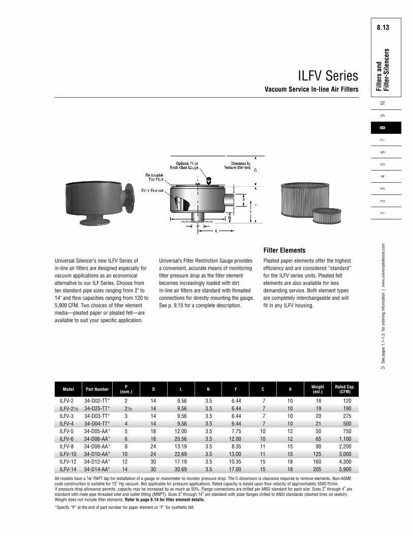
ILFV SeriesVacuum Service In-line Air Filters
All models have a ¹⁄₈" FNPT tap for installation of a gauge or manometer to monitor pressure drop. The C dimension is clearance required to remove elements. Non-ASMEcode construction is suitable for 15" Hg vacuum. Not applicable for pressure applications. Rated capacity is based upon flow velocity of approximately 5500 ft/min. If pressure drop allowance permits, capacity may be increased by as much as 50%. Flange connections are drilled per ANSI standard for each size. Sizes 2" through 4" arestandard with male pipe threaded inlet and outlet fitting (MNPT). Sizes 5" through 14" are standard with plate flanges drilled to ANSI standards (dashed lines on sketch).Weight does not include filter elements. Refer to page 8.14 for filter element details.
*Specify “P” at the end of part number for paper element or “F” for synthetic felt.
Filter ElementsPleated paper elements offer the highestefficiency and are considered “standard”for the ILFV series units. Pleated feltelements are also available for lessdemanding service. Both element types are completely interchangeable and will fit in any ILFV housing.
Universal’s Filter Restriction Gauge providesa convenient, accurate means of monitoringfilter pressure drop as the filter elementbecomes increasingly loaded with dirt.In-line air filters are standard with threadedconnections for directly mounting the gauge.See p. 9.15 for a complete description.
ILFV-2ILFV-2¹⁄₂
ILFV-3ILFV-4ILFV-5ILFV-6ILFV-8ILFV-10ILFV-12ILFV-14
Model
34-D02-TT*34-D25-TT*34-D03-TT*34-D04-TT*34-D05-AA*34-D06-AA*34-D08-AA*34-D10-AA*34-D12-AA*34-D14-AA*
Part Number
22¹⁄₂
34568
101214
P(nom.)
14141414181824243030
D
9.569.569.569.56
12.0020.5613.1922.6917.1930.69
L
3.53.53.53.53.53.53.53.53.53.5
N
6.446.446.446.447.75
12.008.35
13.0010.3517.00
Y
7777
101011111515
C
10101010121215151818
K
18192021506590
125160205
Weight(est.)
120190275500750
1,1002,2003,0004,3005,900
Rated Cap.(CFM)
Universal Silencer’s new ILFV Series ofin-line air filters are designed especially forvacuum applications as an economicalalternative to our ILF Series. Choose fromten standard pipe sizes ranging from 2" to14" and flow capacities ranging from 120 to5,900 CFM. Two choices of filter elementmedia—pleated paper or pleated felt—areavailable to suit your specific application.

Rota
ry P
ositi
ve
Blow
er S
ilenc
ers
8.14Fi
lters
and
Fi
lter-
Sile
ncer
s1
23
45
67
109
8.14Se
e pa
ges
1.1–
1.3
for o
rder
ing
info
rmat
ion
| w
ww
.uni
vers
alsi
lenc
er.c
om8
Filter Elements
34568
1012141618
81-106381-106381-106381-047581-0475 (2)81-116381-116381-116481-116481-1164
81-120581-120581-120581-120781-1207 (2)81-120981-120981-121081-121081-1210
81-103881-103881-103881-104081-1040 (2)81-120081-120081-120181-120181-1201
P(nom.)
Replacement Element Part Number
Paper Felt Wire Mesh
ILF/ILFS Series
22¹⁄₂
34568
101214
81-106381-106381-106381-106381-047581-0475 (2)81-116381-1163 (2)81-116481-1164 (2)
81-120581-120581-120581-120581-120781-1207 (2)81-120981-1209 (2)81-121081-1210 (2)
——————————
P(nom.)
Replacement Element Part Number
Paper Felt Wire Mesh
ILFV Series
Oil Free AdhesiveThis is an oil-free product developed for use on viscousimpingement type filters. It is a substitute for applications that donot permit oil wetting of the filter elements, such as oil-freecompressors. Universal Oil-Free Adhesive is available in 13 oz.aerosol spray cans.
Filter Restriction GaugeThe Filter Restriction Gauge provides a convenient, accuratemeans of monitoring filter pressure drops as the filter elementbecomes increasingly loaded with dirt. Cartridge Filters and Filtersilencers are standard with threaded connections for directmounting of the gauge.
81-0323
81-1234