table of contents - quincie oilfield products other/novatechcatalogue.pdf · in the pump listings:...
TRANSCRIPT

TABLE OF CONTENTS
Catalogue Instructions Page 2
Part Number Listings by Pumps Page 3-14
Price List Page 15
Flyer “About Novatech” Page 17
Flyer “Novatech Well Service Valves & Seats” Page 18
Flyer “Novatech Full Open Drilling Valves & Seats” Page 19
Flyer “Novatech Full Open Drilling Valves & Seats, Design Details” Page 20
Flyer “Novatech Full Open Drilling Valves & Seats, Fluid End Advantages” Page 21
Flyer “Novatech Full Open Drilling Valves & Seats, Inserts” Page 22
Flyer “Novatech Full Open Drilling Valves & Seats, Puller Heads” Page 23
Flyer “Novatech Stem Guided Drilling Valves, Seats, & Inserts” Page 24
Flyer “Novatech Pistons” Page 25
Novatech Limited http://www.novatechmfg.com 8388 C.F. Hawn Freeway
Dallas, Texas 75217 (214) 398-1491 (800) 328-1491
214-398-2214 (FAX)

Page 2
NOVATECH VALVE & SEAT CATALOGUE The following footnotes apply throughout this catalogue. Footnotes correlate with pictures below. 1 Denotes Full Open Valves with Cast-N-Place™ non-replaceable Inserts. Valves and Seats
interchangeable with Harrisburg Roughneck Valves and Seats 2 Denotes Full Open Valves with special High Temperature Cast-N-Place™ non-replaceable Inserts.
Valves and Seats interchangeable with Harrisburg Roughneck Valves and Seats 3 Denotes Full Open Valves with Replaceable Novatech “Snap-On” Inserts. Inserts not interchangeable
with Harrisburg Roughneck Inserts. Valves and Seats interchangeable with Harrisburg Roughneck 4 Denotes Stem Guided Valves with Cast-N-Place™ non-replaceable Inserts, one-piece valve body.
Valves and Seats interchangeable with Mission Supreme Valves and Seats 5 Denotes Stem Guided Valves with Replaceable Inserts. Threaded Retainer Plate, Inserts, Valves and
Seats interchangeable with Mission Supreme Valves and Seats * Denotes Well Service Valves with Replaceable Novatech “Snap-On” Inserts. Inserts interchangeable
with Harrisburg Roughneck Inserts. Valves & Seats interchangeable with Roughneck Valves & Seats In the pump listings: Part Numbers above the underline denote Mud Pump Full Open Valve and Seat
Part Numbers below the underline denote Stem Guided Valve and Web Seat # Denotes Optional Valve, Seat, or Spring for these pumps only!
1 2 3
4
5 *
Cast-N-Place™ is a Trademark of Novatech Limited and is protected by U. S. Patent No. 6,955,181. Catalogue Dated: March 13, 2006

Page 3
Pump Model
Plunger Size
Valve Part #
Seat Part #
Spring Part #
Insert Part #
Cage Part #
Puller Part #
APLEX SC 300L Discharge
Suction ND-4-V1*
ND-4-V1* ND-4-S3 ND-4-S2
5710-33 5710-33
NF-4-I NF-4-I
ND-4-C1 ND-4-C1
ND-4-PH ND-4-PH
BA0JI 1600 1300
ND-7-V21
ND-7-V2H2
ND-7-V13 ND-7-EEF4
NU5C-EEF5
ND-7-S1 ND-7-S1 ND-7-S1 N7DDB1 N7DDB1
5710-115L 5710-115L 5710-115L 5710-115 5710-115
ND-7-I
NUDD-7B
ND-7-PH ND-7-PH ND-7-PH
1000 800
ND-6-V21
ND-6-V2H2
ND-6-V13 ND-6-EH4 NU5B-EH5
ND-6-S6 ND-6-S6 ND-6-S6
N6ADDB6 N6ADDB6
5710-115 5710-115 5710-115 5710-115 5710-115
ND-6-I
NUDD-6AB
ND-6-PH ND-6-PH ND-6-PH
BJ Pacemaker
(Horizontal Suction) Discharge
Suction
3½-5
NF-4-V1* NF-5-V4*
NF-4-S16 NF-5-S4
1235-84 1235-143
NF-4-I NF-5-I
NF-5-C1
ND-4-PH
Pacemaker (Vertical Suction)
3½-5 NF-5-V1*
NF-5-S1
1235-84
NF-5-I
Pacemaker Suction
Discharge
6
NF-6-V1* NF-5-V1*
NF-6-S2 ND-5-S1
19000-1 19000-2
NF-6-I NF-5-I
NF-6-PH NF-5-PH
BJ – WHEATLEY BJ-8 NF-4-V5* NF-4-S10 1235-84 NF-4-I ND-4-PH
CLARK T-440-A,-B T-380,-A,-B,-S
ND-7-V21
ND-7-V2H2
ND-7-V13 ND-7-EEF4
NU5C-EEF5
ND-7-S1 ND-7-S1 ND-7-S1 N7DDB1 N7DDB1
5710-30 5710-30 5710-30 5710-30 5710-30
ND-7-I
NUDD-7B
ND-7-PH ND-7-PH ND-7-PH
CMW (CLARKSVILLE) H-1600 C-1300 C-1800 J-2000
3¾-4 4½-5 4½-5 5½-6
6½-6¾
NF-4-V1* NF-5-V1*
NF-5-V1-C*1
NF-6-V1* NF-7-V1*
NF-4-S1 NF-5-S1 NF-5-S1 NF-6-S3 NF-7-S1
19000-4 19000-2 19000-2 19000-1
1235-140
NF-4-I NF-5-I
n.a. NF-6-I NF-7-I
ND-4-PH ND-5-PH ND-5-PH NF-6-PH NF-7-PH
DOWELL MD01, ME02, ME03, MF04, TD04, TE04, TE05, TF04-05(Dis), TF06, TF07, TF09, TG05, TG06, TH05, TH08, TL05, TL06, TL07, OG01, OG02, OL02, OL03, FOP1, EOP1, EOP12
Suction
Suction
Suction
Suction
Discharge
NF-5-V1C1
-22.5K NF-5-V1C1
-15K NF-5-V1C1
-10K NF-5-V1C1
-5K NF-5-V1C1
NF-5D-S1
NF-5D-S1
NF-5D-S1
NF-5D-S1
NF-5D-S1
ND-5-PH
ND-5-PH
ND-5-PH
ND-5-PH
ND-5-PH Superscript Numbers or Symbols after each part number are keyed to descriptions on page 1

Page 4
Pump Model
Plunger Size
Valve Part #
Seat Part #
Spring Part #
Insert Part #
Cage Part #
Puller Part #
ELLIS WILLIAMS 14-W-400 ND-7-V21
ND-7-V2H2
ND-7-V13 ND-7-EEF4
NU5C-EEF5
ND-7-S1 ND-7-S1 ND-7-S1 N7DDB1 N7DDB1
5710-32 5710-32 5710-32 5710-32 5710-32
ND-7-I
NUDD-7B
ND-7-PH ND-7-PH ND-7-PH
15-W-600 16-W-800
ND-8-V21 ND-8-S2 5710-32 ND-8-PH
W-1000, 9-W-1000 W-600, WH-600
ND-6-V21
ND-6-V2H2
ND-6-V13 ND-6-EH4 NU5B-EH5
ND-6-S6 ND-6-S6 ND-6-S6 N6ADDB6N6ADDB6
5710-115 5710-115 5710-115 5710-115 5710-115
ND-6-I
NUDD-6AB
ND-6-PH ND-6-PH ND-6-PH
W-3000 ND-8-V21 ND-8-S2 5710-115L ND-8-PH W-1400, W-2000 ND-7-V21
ND-7-V2H2
ND-7-V13 ND-7-EEF4
NU5C-EEF5
ND-7-S1 ND-7-S1 ND-7-S1 N7DDB1 N7DDB1
5710-115L 5710-115L 5710-115L 5710-115 5710-115
ND-7-I
NUDD-7B
ND-7-PH ND-7-PH ND-7-PH
W-440-LP, W-446 WH-440
NF-4-V7* NF-4-V2*#
NF-4-S5 5710-38 5710-113#
NF-4-IA ND-4-PH
W-440-HP Suction Discharge
NF-2-V1* NF-4-V2*
NF-2-S2 NF-4-S5
5710-17 5710-38
NF-2-I NF-4-IA
NF-2-C1 ND-4-PH
W-250-B,-C NF-2-V1* NF-2-S2 5710-17 NF-2-I NF-2-C1 Superscript Numbers or Symbols after each part number are keyed to descriptions on page 1

Page 5
Pump Model
Plunger Size
Valve Part #
Seat Part #
Spring Part #
Insert Part #
Cage Part #
Puller Part #
EMSCO D-850, DC-850 DC-1000, DC-1650 DC-1350, DB-700 D-550, DA-500 DB-550, C-16, B-14
ND-8-V21 ND-8-S2 5710-32 ND-8-PH
CA-16, D-16, D-500 D-300, BA-14, D-14 D-375
ND-7-V21
ND-7-V2H2
ND-7-V13 ND-7-EEF4
NU5C-EEF5
ND-7-S1 ND-7-S1 ND-7-S1 N7DDB1 N7DDB1
5710-30 5710-30 5710-30 5710-30 5710-30
ND-7-I
NUDD-7B
ND-7-PH ND-7-PH ND-7-PH
D-225, D-125 ND-6-V21
ND-6-V2H2
ND-6-V13 ND-6-EH4 NU5B-EH5
ND-6-S6 ND-6-S6 ND-6-S6
N6ADDB6 N6ADDB6
5710-30 5710-30 5710-30 5710-30 5710-30
ND-6-I
NUDD-6AB
ND-6-PH ND-6-PH ND-6-PH
D-175, D-12, A-10 ND-5-V21 ND-5-S4 5710-30 ND-5-PH FC-2200 ND-8-V21 ND-8-S2 5710-115L ND-8-PH F-1300, F-1600 FA-1300, FA-1600 FA-1300 II, FA-1600 II FB-1300, FB-1600 FC-1300, FC-1600
ND-7-V21
ND-7-V2H2
ND-7-V13 ND-7-EEF4
NU5C-EEF5
ND-7-S1 ND-7-S1 ND-7-S1 N7DDB1 N7DDB1
5710-115L 5710-115L 5710-115L 5710-115 5710-115
ND-7-I
NUDD-7B
ND-7-PH ND-7-PH ND-7-PH
F-800, F-1000 ND-6-V21
ND-6-V2H2
ND-6-V13 ND-6-EH4 NU5B-EH5
ND-6-S6 ND-6-S6 ND-6-S6
N6ADDB6 N6ADDB6
5710-115 5710-115 5710-115 5710-115 5710-115
ND-6-I
NUDD-6AB
ND-6-PH ND-6-PH ND-6-PH
F-750, F-650 F-500, F-350
ND-5-V21 ND-5-S1 5710-30 ND-5-PH
F-350P ND-4-V1* NF-4-S5 5710-33 5710-78#
NF-4-I ND-4-PH
F-350HP (Piston & Plunger)
NF-2-V1* NF-2-S8 5710-03 NF-2-I NF-2-C1
FAILING FM-45 NF-4-V5* NF-4-S8 5710-03 NF-4-I ND-4-PH L-100 NF-3-V6* NF-3-S6 5710-03 F-3-IA
FAIRBANKS MORSE Fig. 6188 ND-7-V21
ND-7-V2H2
ND-7-V13 ND-7-EEF4
NU5C-EEF5
ND-7-S1 ND-7-S1 ND-7-S1 N7DDB1 N7DDB1
ND-7-I
NUDD-7B
ND-7-PH ND-7-PH ND-7-PH
Fig. 6285, 6185, 6183 NF-4-V5* NF-4-S8 5710-03 NF-4-I ND-4-PH Fig. 6182, 6181 NF-3-V6* NF-3-S6 5710-03 NF-3-IA Superscript Numbers or Symbols after each part number are keyed to descriptions on page 1

Page 6
Pump Model
Plunger Size
Valve Part #
Seat Part #
Spring Part #
Insert Part #
Cage Part #
Puller Part #
GARDNER DENVER (DUPLEX) KJ-KXJ-B, GN-GXQ GQ-GXO, GN-GXN GQ-GXN, FK-FXK
ND-8-V21 ND-8-S2 5710-32 ND-8-PH
EJ-EQ, EN-EQ EN-EXQ, EJ-FXQ EN-EN, EJ-EN EJ-EXN, EN-EXN FZ-FXZ, FY-FXX FY-FS, FY-FXD FO-FXO, FO-2000 FO-FXO-A Thru -K
ND-7-V21
ND-7-V2H2
ND-7-V13 ND-7-EEF4
NU5C-EEF5
ND-7-S5 ND-7-S5 ND-7-S5 N7DDB5 N7DDB5
5710-32 5710-32 5710-32 5710-32 5710-32
ND-7-I
NUDD-7B
ND-7-PH ND-7-PH ND-7-PH
FXN, EK-EK, EK-EXK ND-7-V21
ND-7-V2H2
ND-7-V13 ND-7-EEF4
NU5C-EEF5
ND-7-S1 ND-7-S1 ND-7-S1 N7DDB1 N7DDB1
5710-32 5710-32 5710-32 5710-32 5710-32
ND-7-I
NUDD-7B
ND-7-PH ND-7-PH ND-7-PH
FXZ-FXZ –H, -J FXO-FXO, -B, -L, -M
ND-5-V21 ND-5-S5 5710-30 ND-5-PH
FD-FS, FD-FJ-A FD-FJ-B, FD-FXD FC-FS, EF-FS EF-2000, FD-FXX FG-FXG, -P, -R, -T FG-AG, FG-AG-B FG-AG-D, FG-2000 FG-4000, FG-FXG FG-FXG -A Thru -L FD-FXX-J
NF-4-V5* NF-4-S8 5710-03 NF-4-I ND-4-PH
EF-FXD, EF-PXD FC-FXD-A Thru -L FC-FXD, FC-FXO EW, EW-1000, FJ-FS EW-FJ, FJ-FJ EW-PXD, EF, ET ET-PXD, FA-FXX FC-FXX-A Thru -M, -V FC-FXX-S EF-FXX-AS Thru -D
NF-4-V7* NF-4-S2 5710-03 NF-4-IA ND-4-PH
FC-FXD-R Thru -Z FC-FXX-Z FC-FXX -AA Thru -AG
NF-4-V7* NF-4-S12 5710-03 NF-4-IA ND-4-PH
LF-5, FF-AF, FF-AXF FF-2000, FF-4000 FF-FXF, -A Thru -E, -M
NF-3-V6* NF-3-S6 5710-03 NF-3-IA
LF-5, FF-AF, FF-AXF FF-2000, FF-4000 FF-FXF, -A Thru -E, -M
NF-3-V6* NF-3-S6 5710-03 NF-3-IA
Superscript Numbers or Symbols after each part number are keyed to descriptions on page 1

Page 7
Pump Model
Plunger Size
Valve Part #
Seat Part #
Spring Part #
Insert Part #
Cage Part #
Puller Part #
GARDNER DENVER (TRIPLEX) GD 3000HP Medium Pressure F.E Med-High Pressure F. E. High Pressure F. E.
NF-6-V1*
NF-6-V1-C*1 NF-6-V1*
NF-6-V1-C*1
NF-5-V1* NF-5-V1-C*1
NF-6-S3 NF-6-S3
NF-6H-S3 NF-6H-S3 NF-5-S1 NF-5-S1
NF-6-I
NF-6-I
NF-5-I
NF-6-PH NF-6-PH NF-6-PH NF-6-PH ND-5-PH ND-5-PH
GWS
5 NF-5-V1* NF-5-V1-C*1
NF-5D-S1
NF-5-I ND-5-PH
PZ- L(11) -A Thru –F PZ-K(10) PZ-J(9) -C, -D PZ-H(8) -E, VE PZ-G(7) -A, -B
ND-7-V21
ND-7-V2H2 ND-7-V13
ND-7-EEF4 NU5C-EEF5
ND-7-S1 ND-7-S1 ND-7-S1 N7DDB1 N7DDB1
5710-115L 5710-115L 5710-115L 5710-115 5710-115
ND-7-I
NUDD-7B
ND-7-PH ND-7-PH ND-7-PH
PXL PZ- L(11), PZ-K(10) With 7500 psi. Fluid End API 6 valves & Seats
ND-6-V21
ND-6-V2H2 ND-6-V13 ND-6-EH4 NU5B-EH5
ND-6-S6 ND-6-S6 ND-6-S6
N6ADDB6 N6ADDB6
5710-115 5710-115 5710-115 5710-115 5710-115
ND-6-I
NUDD-6AB
ND-6-PH ND-6-PH ND-6-PH
PZ-9 -A, -B, PV-9 PZ-8 -A, -B, -D PO-7 PY-7 -A, -C, -E, -G
ND-5-V21 ND-5-S1 5710-30 ND-5-PH
PJ-8A, -B PJHB PAHAA, -D, -E, -F, -J, -K PAH-BFB, -BFC PAHBF, TGF, TGH
ND-4-V1* NF-4-S5 5710-33 5710-78#
NF-4-I ND-4-PH
PA-8C, -D, -E NF-4-V7* NF-4-S2 5710-17 NF-4-IA ND-4-PH PA-8H, -K, -L, -Q, PA-8R, -S, -U, -Y
NF-4-V7* NF-4-S12 5710-17 NF-4-IA ND-4-PH
PA-8N, TEEA-D PAHAA (Plunger Model) PAHAF (Plunger Model) PE-5C, -J
NF-2-V1* NF-2-S2 5710-03 NF-2-I NF-2-C1
PE-5T, -Z TEEBFB, TEEBFC, TEED-D, TEEE-D, TEEB-D 2 Inch Seat ID 2.375 Inch Seat ID
NF-2-V1*
NF-2-V3*#
NF-2-S5
NF-2-S9 #
5710-03 5710-03
NF-2-I
NF-2-IA
NF-2-C1 NF-2-C1
PE-5F, -G, -H, -K, -L, Q PE-5R, -T, -V, -W, -X PE-5Y, -Z, -AA, -AB TEEBCA, -BGB, -BFA
NF-1A-V1* NF-1A-S1 5710-03 NF-1A-I NF-1A-C1
GASO Fig. 550, 1550, 1550C, 1560, 1563, 2050, 1847 1860, 2247, 1849, 2249
NF-4-V7* NF-4-S7 5710-33 NF-4-IA ND-4-PH
3968, 3969, 3671WS 3673, 3675, 5885WS, 3775, 3776
NF-3-V6* NF-3-S9 5710-17 NF-3-IA NF-3-C1
Fig. 1742, 1755, 1654, 1654C, 1757
NF-4-V7* NF-4-S13A 5710-05 NF-4-IA ND-4-PH
Superscript Numbers or Symbols after each part number are keyed to descriptions on page 1
Page 8
Pump Model
Plunger Size
Valve Part #
Seat Part #
Spring Part #
Insert Part #
Cage Part #
Puller Part #
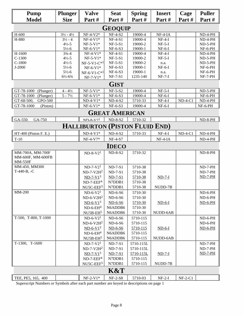
GEOQUIP H-600 3½ - 4½ NF-4-V2* NF-4-S2 19000-4 NF-4-IA ND-4-PH H-880 3½ - 4
4½-5 5½-6
NF-4-V1* NF-5-V1* NF-6-V1*
NF-4-S1 NF-5-S1 NF-6-S3
19000-4 19000-2 19000-1
NF-4-I NF-5-I NF-6-I
ND-4-PH ND-5-PH NF-6-PH
H-1600 C-1300 C-1800 J-2000
3¾-4 4½-5 4½-5 5½-6 5½-6
6½-6¾
NF-4-V1* NF-5-V1*
NF-5-V1-C*1
NF-6-V1* NF-6-V1-C*1
NF-7-V1*
NF-4-S1 NF-5-S1 NF-5-S1 NF-6-S3 NF-6-S3 NF-7-S1
19000-4 19000-2 19000-2 19000-1 19000-1
1235-140
NF-4-I NF-5-I
n.a. NF-6-I
n.a. NF-7-I
ND-4-PH ND-5-PH ND-5-PH NF-6-PH NF-6-PH NF-7-PH
GIST GT-78-1000 (Plunger) 4 - 4½ NF-5-V1* NF-5-S2 19000-4 NF-5-I ND-5-PH GT-78-1000 (Plunger) 5 - 7½ NF-6-V1* NF-6-S3 19000-4 NF-6-I NF-6-PH GT-68-500, GPO-500 ND-4-V1* ND-4-S2 5710-33 NF-4-I ND-4-C1 ND-4-PH GT-78-1000 (Piston) NF-6-V1* NF-6-S3 19000-4 NF-6-I NF-6-PH
GREAT AMERICAN GA-550, GA-750 ND-8-V21 ND-8-S2 5710-32 ND-8-PH
HALLIBURTON (PISTON FLUID END) HT-400 (Piston F. E.) ND-4-V1* ND-4-S2 5710-33 NF-4-I ND-4-C1 ND-4-PH T-10 NF-4-V7* NF-4-S7 NF-4-IA ND-4-PH
IDECO MM-700A, MM-700F MM-600F, MM-600FB MM-550F
ND-8-V21 ND-8-S2 5710-32 ND-8-PH
MM-450, MM300 T-440-B, -C
ND-7-V21
ND-7-V2H2
ND-7-V13 ND-7-EEF4
NU5C-EEF5
ND-7-S1 ND-7-S1 ND-7-S1 N7DDB1 N7DDB1
5710-38 5710-38 5710-38 5710-38 5710-38
ND-7-I
NUDD-7B
ND-7-PH ND-7-PH ND-7-PH
MM-200 ND-6-V21
ND-6-V2H2
ND-6-V13 ND-6-EH4 NU5B-EH5
ND-6-S6 ND-6-S6 ND-6-S6
N6ADDB6 N6ADDB6
5710-30 5710-30 5710-30 5710-30 5710-30
ND-6-I
NUDD-6AB
ND-6-PH ND-6-PH ND-6-PH
T-500, T-800, T-1000 ND-6-V21
ND-6-V2H2
ND-6-V13 ND-6-EH4 NU5B-EH5
ND-6-S6 ND-6-S6 ND-6-S6
N6ADDB6 N6ADDB6
5710-115 5710-115 5710-115 5710-115 5710-115
ND-6-I
NUDD-6AB
ND-6-PH ND-6-PH ND-6-PH
T-1300, T-1600 ND-7-V21
ND-7-V2H2
ND-7-V13 ND-7-EEF4
NU5C-EEF5
ND-7-S1 ND-7-S1 ND-7-S1 N7DDB1 N7DDB1
5710-115L 5710-115L 5710-115L 5710-115 5710-115
ND-7-I
NUDD-7B
ND-7-PH ND-7-PH ND-7-PH
K&T TEE, PE5, 165, 400 NF-2-V1* NF-2-S8 5710-03 NF-2-I NF-2-C1 Superscript Numbers or Symbols after each part number are keyed to descriptions on page 1

Page 9
Pump Model
Plunger Size
Valve Part #
Seat Part #
Spring Part #
Insert Part #
Cage Part #
Puller Part #
NATIONAL N-1600, N-1300, N-900 N-1100, N-1000 H-1250 “N” Type G-1000-C “N” Type E-700 “N” Type
ND-8-V21 ND-8-S7 5710-32 ND-8-PH
K-700A, K-500(Cast) K-500(Forged) C-250(Forged)
ND-8-V21 ND-8-S2 5710-32 ND-8-PH
K-380, K-280, K-180 C-150B, C-150
ND-7-V21
ND-7-V2H2
ND-7-V13 ND-7-EEF4
NU5C-EEF5
ND-7-S1 ND-7-S1 ND-7-S1 N7DDB1 N7DDB1
5710-32 5710-32 5710-32 5710-32 5710-32
ND-7-I
NUDD-7B
ND-7-PH ND-7-PH ND-7-PH
KSH-280, KSH-180 ND-6-V21
ND-6-V2H2
ND-6-V13 ND-6-EH4 NU5B-EH5
ND-6-S6 ND-6-S6 ND-6-S6 N6ADDB6N6ADDB6
5710-32 5710-32 5710-32 5710-32 5710-32
ND-6-I
NUDD-6AB
ND-6-PH ND-6-PH ND-6-PH
14-P-200, 14-P-220 ND-8-V2¹ ND-8-S7 5710-115L ND-8-PH 12-P-160 ND-7-V21
ND-7-V2H2
ND-7-V13 ND-7-EEF4
NU5C-EEF5
ND-7-S12 ND-7-S12 ND-7-S12 N7DDB12 N7DDB12
5710-115L 5710-115L 5710-115L 5710-115 5710-115
ND-7-I
NUDD-7B
ND-7-PH ND-7-PH ND-7-PH
10-P-130, 9-P-100 8-P-80
ND-6-V21
ND-6-V2H2
ND-6-V13 ND-6-EH4 NU5B-EH5
ND-6-S4 ND-6-S4 ND-6-S4 N6ADDB4N6ADDB4
5710-115 5710-115 5710-115 5710-115 5710-115
ND-6-I
NUDD-6AB
ND-6-PH ND-6-PH ND-6-PH
7-P-50 ND-5-V21 ND-5-S3 5710-115 NF-5-I ND-5-PH JWS-400 Suction Suction (Pistons) Discharge Discharge
NF-3-V4* NF-3-V3*# NF-3-V4*
NF-3-V3*#
NF-3-S11 NF-3-S11 NF-3-S10 NF-3-S10
19000-5 19000-5
5710-115 5710-115
NF-3-I NF-3-I NF-3-I NF-3-I
JWS-165L Suction JWS-5L Suction JWS-300L Discharge Discharge
NF-4-V7* NF-4-V2*# NF-4-V7*
NF-4-V2*#
NF-4-S17 NF-4-S17 NF-4-S18 NF-4-S18
19000-6 19000-6
5710-118 5710-118
NF-4-IA NF-4-IA NF-4-IA NF-4-IA
ND-4-PH ND-4-PH ND-4-PH ND-4-PH
JWS-185 Suction JWS-340 Suction Discharge Discharge
NF-4-V7* NF-4-V2*# NF-4-V7*
NF-4-V2*#
NF-4-S17 NF-4-S17 NF-4-S18 NF-4-S18
1560697 1560697 1560697 1560697
NF-4-IA NF-4-IA NF-4-IA NF-4-IA
ND-4-PH ND-4-PH ND-4-PH ND-4-PH
JWS-400 w/Cage Valve JWS-165LX , -300LX
Not Available
Not Available
Not Available
Not Available
D-50 NF-4-V7* NF-4-S13A 5710-06 NF-4-IA ND-4-PH Superscript Numbers or Symbols after each part number are keyed to descriptions on page 1

Page 10
Pump Model
Plunger Size
Valve Part #
Seat Part #
Spring Part #
Insert Part #
Cage Part #
Puller Part #
OFM 1000-1300WS 4 - 4½ NF-5-V1* NF-5-S2 19000-4 NF-5-I ND-5-PH 1000-1300WS 5 - 7½ NF-6-V1* NF-6-S3 19000-4 NF-6-I NF-6-PH 350 AWS, 500 AWS 2¾-3
3½ - 4 4½-5
NF-2-V1* NF-4-V2* NF-5-V1*
NF-2-S1 NF-4-S2 NF-5-S2
1235-141 19000-4 19000-3
NF-2-I NF-4-IA NF-5-I
ND-4-PH ND-5-PH
880 AWS 3½-4 4½-5 5½-6
NF-4-V1* NF-5-V1* NF-6-V1*
NF-4-S1 NF-5-S1 NF-6-S3
19000-4 19000-2 19000-1
NF-4-I NF-5-I NF-6-I
ND-4-PH ND-5-PH NF-6-PH
1000 AWS, 1300 AWS 1600 AWS, 1800 AWS 1600BWS GD-2000
3¾-4 4½-5 4½-5 5½-6 5½-6
6½-7½
NF-4-V1* NF-5-V1*
NF-5-V1-C*1
NF-6-V1* NF-6-V1-C*1
NF-7-V1*
NF-4-S1 NF-5-S1 NF-5-S1 NF-6-S3 NF-6-S3 NF-7-S1
19000-4 19000-2 19000-2 19000-1 19000-1
1235-140
NF-4-I NF-5-I
n.a. NF-6-I
n.a. NF-7-I
ND-4-PH ND-5-PH ND-5-PH NF-6-PH NF-6-PH NF-7-PH
700D (Piston) NF-6-V1* NF-6-S3 19000-4 NF-6-I NF-6-PH 350 D, 350 DG ND-4-V1* ND-4-S2 5710-33 NF-4-I ND-4-C1 ND-4-PH 350 DWS NF-5-V1* NF-5-S2 19000-4 NF-5-I 500 DC, 600 D 700 DL, 700 DL
ND-6-V21
ND-6-V2H2
ND-6-V13 ND-6-EH4 NU5B-EH5
ND-6-S6 ND-6-S6 ND-6-S6
N6ADDB6 N6ADDB6
5710-115 5710-115 5710-115 5710-115 5710-115
ND-6-I
NUDD-6AB
ND-6-PH ND-6-PH ND-6-PH
Superscript Numbers or Symbols after each part number are keyed to descriptions on page 1

Page 11
Pump Model
Plunger Size
Valve Part #
Seat Part #
Spring Part #
Insert Part #
Cage Part #
Puller Part #
OILWELL 1700-P, 1400-P ND-8-V21 ND-8-S2 5710-32 ND-8-PH 510-P, 6-P-LD NF-3-V4* NF-3-S3 5710-32 NF-3-I 6-P, 6-P-HD NF-2-V3* NF-2-S10 5710-03 NF-2-IA 1400-PT, 1700-PT A1400-PT, A1700-PT 1100-PT, 850-PT A1100-PT, A850-PT HD1700PT
ND-7-V21
ND-7-V2H2
ND-7-V13 ND-7-EEF4
NU5C-EEF5
ND-7-S1 ND-7-S1 ND-7-S1 N7DDB1 N7DDB1
5710-115L 5710-115L 5710-115L 5710-115 5710-115
ND-7-I
NUDD-7B
ND-7-PH ND-7-PH ND-7-PH
A600PT, A560-PT 350-PT
ND-6-V21
ND-6-V2H2
ND-6-V13 ND-6-EH4 NU5B-EH5
ND-6-S6 ND-6-S6 ND-6-S6
N6ADDB6 N6ADDB6
5710-115 5710-115 5710-115 5710-115 5710-115
ND-6-I
NUDD-6AB
ND-6-PH ND-6-PH ND-6-PH
46P, 346P, 326P NF-3-V3* NF-34-S3 5710-03 NF-3-I SA-625-5, SA-626-5 SA-630-5, SA-634-5
NF-2-V1* NF-2-S1 NF-2-I
SA-640-5, SA-650 NF-4-V2* NF-4-S2 5710-38 NF-4-IA ND-4-PH SB-644-5, SA-644-5 SA-644-10, SA-650-5 SA-650-10, SB-650-5
NF-5-V1* NF-5-S2 NF-5-I ND-5-PH
S-620 Suction S-615 Discharge
NF-2-V2* NF-2-V1*
NF-2-S6 NF-2-S7
NF-2-I NF-2-I
S-610 Suction
Discharge
NF-4-V3* NF-3-V3*
NF-4-S4 NF-3-S4
NF-4-I NF-3-I
Super 48, S824, SA824 S856-6, SA-656-6
NF-7-V1* NF-7-S1 5710-115L NF-7-I NF-7-PH
48-P-HD, 58-P-D NF-4-V2* NF-4-S13A 5710-03 NF-4-IA ND-4-PH S-830, SA-830, SA-830 NF-4-V2* NF-4-S13A 1235-137 NF-4-IA ND-4-PH Superscript Numbers or Symbols after each part number are keyed to descriptions on page 1

Page 12
Pump Model
Plunger Size
Valve Part #
Seat Part #
Spring Part #
Insert Part #
Cage Part #
Puller Part #
OMEGA 1000-1300HP 4 - 4½ NF-5-V1* NF-5-S2 19000-4 NF-5-I ND-5-PH 1000-1300HP 5 - 7½ NF-6-V1* NF-6-S3 19000-4 NF-6-I NF-6-PH 1300HP “MF” F.E. 1800HP “MF” F.E.
3¾-4 4½-5 4½-5 5½-6 5½-6
6½-6¾
NF-4-V1* NF-5-V1*
NF-5-V1-C*1
NF-6-V1* NF-6-V1-C*1
NF-7-V1*
NF-4-S1 NF-5-S1 NF-5-S1 NF-6-S3 NF-6-S3 NF-7-S1
19000-4 19000-2 19000-2 19000-1 19000-1
1235-140
NF-4-I NF-5-I
n.a. NF-6-I
n.a. NF-7-I
ND-4-PH ND-5-PH ND-5-PH NF-6-PH NF-6-PH NF-7-PH
D-750 (Piston) NF-6-V1* NF-6-S3 19000-4 NF-6-I NF-6-PH D-750L (Piston)
ND-6-V21
ND-6-V2H2
ND-6-V13 ND-6-EH4 NU5B-EH5
ND-6-S6 ND-6-S6 ND-6-S6
N6ADDB6 N6ADDB6
5710-115 5710-115 5710-115 5710-115 5710-115
ND-6-I
NUDD-6AB
ND-6-PH ND-6-PH ND-6-PH
OPI 1000-1300WS 4 - 4½ NF-5-V1* NF-5-S2 19000-4 NF-5-I ND-5-PH 1000-1300WS 5 - 7½ NF-6-V1* NF-6-S3 19000-4 NF-6-I NF-6-PH 350 AWS, 500 AWS 2¾-3
3½ - 4 4½-5
NF-2-V1* NF-4-V2* NF-5-V1*
NF-2-S1 NF-4-S2 NF-5-S2
1235-141 19000-4 19000-3
NF-2-I NF-4-IA NF-5-I
ND-4-PH ND-5-PH
880 AWS 3½-4 4½-5 5½-6
NF-4-V1* NF-5-V1* NF-6-V1*
NF-4-S1 NF-5-S1 NF-6-S3
19000-4 19000-2 19000-1
NF-4-I NF-5-I NF-6-I
ND-4-PH ND-5-PH NF-6-PH
1000 AWS, 1300 AWS 1600 AWS, 1800 AWS 1600BWS GD-2000
3¾-4 4½-5 4½-5 5½-6 5½-6
6½-7½
NF-4-V1* NF-5-V1*
NF-5-V1-C*1
NF-6-V1* NF-6-V1-C*1
NF-7-V1*
NF-4-S1 NF-5-S1 NF-5-S1 NF-6-S3 NF-6-S3 NF-7-S1
19000-4 19000-2 19000-2 19000-1 19000-1
1235-140
NF-4-I NF-5-I
n.a. NF-6-I
n.a. NF-7-I
ND-4-PH ND-5-PH ND-5-PH NF-6-PH NF-6-PH NF-7-PH
700D (Piston) NF-6-V1* NF-6-S3 19000-4 NF-6-I NF-6-PH 350 D, 350 DG ND-4-V1* ND-4-S2 5710-33 NF-4-I ND-4-C1 ND-4-PH 350 DWS NF-5-V1* NF-5-S2 19000-4 NF-5-I ND-5-PH 500 DC, 600 D 700 DL, 700 HDL
ND-6-V21
ND-6-V2H2
ND-6-V13 ND-6-EH4 NU5B-EH5
ND-6-S6 ND-6-S6 ND-6-S6
N6ADDB6 N6ADDB6
5710-115 5710-115 5710-115 5710-115 5710-115
ND-6-I
NUDD-6AB
ND-6-PH ND-6-PH ND-6-PH
1000 HDL, 1300 HDL ND-7-V21
ND-7-V2H2
ND-7-V13 ND-7-EEF4
NU5C-EEF5
ND-7-S1 ND-7-S1 ND-7-S1 N7DDB1 N7DDB1
5710-115L 5710-115L 5710-115L 5710-115 5710-115
ND-7-I
NUDD-7B
ND-7-PH ND-7-PH ND-7-PH
PINION RB5, RB6 NF-5-V1* NF-5-S2 19000-4 NF-5-I ND-5-PH Superscript Numbers or Symbols after each part number are keyed to descriptions on page 1

Page 13
Pump Model
Plunger Size
Valve Part #
Seat Part #
Spring Part #
Insert Part #
Cage Part #
Puller Part #
SKYTOP BREWSTER B-1000F, B-750F B-550F, B-500
ND-8-V21 ND-8-S2 5710-32 ND-8-PH
B-1300T, B-1600T ND-7-V21
ND-7-V2H2
ND-7-V13 ND-7-EEF4
NU5C-EEF5
ND-7-S1 ND-7-S1 ND-7-S1 N7DDB1 N7DDB1
5710-115L 5710-115L 5710-115L 5710-115 5710-115
ND-7-I
NUDD-7B
ND-7-PH ND-7-PH ND-7-PH
B-1000T, B-1100T ND-6-V21
ND-6-V2H2
ND-6-V13 ND-6-EH4 NU5B-EH5
ND-6-S6 ND-6-S6 ND-6-S6
N6ADDB6 N6ADDB6
5710-115 5710-115 5710-115 5710-115 5710-115
ND-6-I
NUDD-6AB
ND-6-PH ND-6-PH ND-6-PH
SOUTHWEST FLUID ENDS Duplex Pump “IVP” Fluid End
ND-7-V21
ND-7-V2H2
ND-7-V13 ND-7-EEF4
NU5C-EEF5
ND-7-S1 ND-7-S1 ND-7-S1 N7DDB1 N7DDB1
5710-32 5710-32 5710-32 5710-32 5710-32
ND-7-I
NUDD-7B
ND-7-PH ND-7-PH ND-7-PH
SPM TWS 400, TWS 600 TWS 500LW
3½ - 4½ NF-4-V2* NF-4-S2 19000-4 NF-4-IA ND-4-PH
TWS 900 3½-4 4½-5 5½-6
NF-4-V1* NF-5-V1* NF-6-V1*
NF-4-S1 NF-5-S1 NF-6-S3
19000-4 19000-2 19000-1
NF-4-I NF-5-I NF-6-I
ND-4-PH ND-5-PH NF-6-PH
TWS 1300, TWS 1600 TWS 1800 TWS 1600LW QWS 2000 2500LW
3¾-4 4½-5 4½-5 5½-6 5½-6
6½-7½
NF-4-V1* NF-5-V1*
NF-5-V1-C*1
NF-6-V1* NF-6-V1-C*1
NF-7-V1*
NF-4-S1 NF-5-S1 NF-5-S1 NF-6-S3 NF-6-S3 NF-7-S1
19000-4 19000-2 19000-2 19000-1 19000-1
1235-140
NF-4-I NF-5-I
n.a. NF-6-I
n.a. NF-7-I
ND-4-PH ND-5-PH ND-5-PH NF-6-PH NF-6-PH NF-7-PH
TULSA RIG IRON TT-250 2 Inch Seat ID 2.375 Inch Seat ID
NF-2-V1*
NF-2-V3*#
NF-2-S5
NF-2-S9 #
5710-03 5710-03
NF-2-I
NF-2-IA
NF-2-C1 NF-2-C1
TT-350 ND-4-V1* NF-4-S5 5710-33 5710-78#
NF-4-I ND-4-PH
Superscript Numbers or Symbols after each part number are keyed to descriptions on page 1

Page 14
Pump Model
Plunger Size
Valve Part #
Seat Part #
Spring Part #
Insert Part #
Cage Part #
Puller Part #
WESTERN RB 80, RB 81 NF-5-V1* NF-5-S2 1235-84 NF-5-I ND-5-PH Roughrider 500 “Mono Block” F.E.
3½ - 4½ NF-4-V2* NF-4-S2 19000-4 NF-4-IA ND-4-PH
Roughrider 500 “Segmented” F.E.
Suction Discharge
Suction Discharge
3½ 3½ 4½ 4½
NF-2-V2* NF-2-V1* NF-4-V3* NF-3-V3*
NF-2-S6 NF-2-S7 NF-4-S4 NF-3-S4
NF-2-I NF-2-I NF-4-I NF-3-I
Roughrider 1000 “Mono Block” F.E.
4 4½ - 5
NF-3-V4* NF-5-V1*
NF-3-S3 NF-5-S2
NF-3-I NF-5-I
ND-5-PH
Roughrider 1500 “Mono Block” F.E.
4 5
NF-3-V4* NF-5-V1*
NF-3-S3 NF-5-S1
NF-3-I NF-5-I
ND-5-PH
WHEATLEY Fig. 6070 ND-7-V21
ND-7-V2H2
ND-7-V13 ND-7-EEF4
NU5C-EEF5
ND-7-S1 ND-7-S1 ND-7-S1 N7DDB1 N7DDB1
5710-32 5710-32 5710-32 5710-32 5710-32
ND-7-I
NUDD-7B
ND-7-PH ND-7-PH ND-7-PH
3F-450, 4F-750 NF-5-V1* NF-5-S2 NF-5-I ND-5-PH BJ-8 NF-4-V1* NF-4-S10 1235-84 NF-4-I ND-4-PH 5830, 5850, 6050-A, 2050-A, 1550-A, 7036, 1336, 1036
NF-4-V5* ND-4-S17 5710-17 NF-4-I ND-4-PH
WILSON 600, 900, Giant ND-8-V21 ND-8-S2 5710-32 ND-8-PH
WIRTH TPK/800, 1000 ND-6-V21
ND-6-V2H2
ND-6-V13
ND-6-S7 ND-6-S7 ND-6-S7
5710-115 5710-115 5710-115
ND-6-I
TPK/1300, 1600, 2000, 2200
ND-7-V21
ND-7-V2H2
ND-7-V13
ND-7-S16 ND-7-S16 ND-7-S16
5710-115L 5710-115L 5710-115L
ND-7-I
WORTHINGTON KKS-1, KLS-1, KMS-1 NF-4-V7* NF-4-S7 5710-3 NF-4-IA ND-4-PH Superscript Numbers or Symbols after each part number are keyed to descriptions on page 1

Page 15

Page 16
Price List Seats List Net Cages List Net Valves List Net Part # Price Price Part # Price Price Part # Price Price
NF-1A-S1 $88.63 $56.50 NF-1A-C1 $ 86.28 $55.00 NF-1A-V1 $69.02 $44.00 NF-1A-S4 84.70 54.00 NF-2-C1 99.21 63.25 NF-2-V1 85.88 54.75 NF-2-S1 83.14 53.00 NF-3-C1 99.21 63.25 NF-2-V2 130.98 83.50 NF-2-S2 106.67 68.00 ND-4-C1 110.59 70.50 NF-2-V3 85.88 54.75 NF-2-S5 104.70 66.75 NF-3-V3 85.88 54.75 NF-2-S6 84.70 54.00 NF-3-V4 85.88 54.75 NF-2-S7 110.20 70.25 Puller Hds List Net NF-3-V6 85.88 54.75 NF-2-S8 106.66 68.00 Part # Price Price NF-4-V1 85.88 54.75 NF-2-S9 104.70 66.75 ND-4-PH $109.80 $70.00 NF-4-V2 85.88 54.75 NF-2-S10 110.20 70.25 ND-5-PH 109.80 70.00 NF-4-V3 125.30 106.50 NF-23-S9 141.96 90.50 ND-6-PH 109.80 70.00 NF-4-V5 85.88 54.75 NF-3-S3 70.19 44.75 NF-6-PH 109.80 70.00 NF-4-V7 85.88 54.75 NF-3-S4 106.66 68.00 ND-7-PH 109.80 70.00 NF-5-V1 89.41 57.00 NF-3-S6 84.70 54.00 NF-7-PH 120.78 77.00 NF-5-V1-C 100.78 64.25 NF-3-S9 106.66 68.00 ND-8-PH 145.10 92.50 NF-5-V1C-15K 238.82 152.25 NF-3-S10 98.43 62.75 NF-5-V1C-22K 238.82 152.25 NF-3-S11 84.70 54.00 Springs List Net NF-5-V4 136.87 87.25 NF-34-S3 138.82 88.50 Part # Price Price NF-6-V1 118.82 75.75 NF-4-S1 69.01 44.00 5710-03 $ 7.92 $5.05 NF-6-V1-C 127.85 81.50 NF-4-S2 69.01 44.00 5710-05 19.22 12.25 NF-7-V1 142.35 90.75 NF-4-S4 123.14 78.50 5710-06 21.49 13.70 ND-4-V1 85.88 54.75 NF-4-S5 70.19 44.75 5710-17 11.29 7.20 ND-5-V2 118.82 75.75 NF-4-S7 71.77 45.75 5710-30 12.47 7.95 ND-6-V1 107.45 68.50 NF-4-S8 71.77 45.75 5710-32 16.94 10.80 ND-6-V2 102.75 65.50 NF-4-S10 94.90 60.50 5710-33 14.75 9.40 ND-6-V2H 154.51 98.50 NF-4-S12 71.77 45.75 5710-38 21.49 13.70 ND-6-V2H-C 154.51 98.50 NF-4-S13A 96.08 61.25 5710-78 14.75 9.40 ND-6-EH 74.51 47.50 NF-4-S16 70.19 44.75 5710-80 14.75 9.40 ND-6-EH-H 128.63 82.00 NF-4-S17 70.59 45.00 5710-110L 11.29 7.20 NU5B-EH 85.10 54.25 NF-4-S18 76.47 48.75 5710-115 10.20 6.50 ND-7-V1 105.10 67.00 NF-5-S1 70.19 44.75 5710-115L 10.20 6.50 ND-7-V2 99.60 63.50 NF-5D-S1 70.19 44.75 5710-118 20.32 12.95 ND-7-V2-H 154.51 98.50 NF-5-S2 70.19 44.75 19000-1 16.93 10.80 ND-7-V2-H-C 154.51 98.50 NF-5-S4 92.16 58.75 19000-2 23.76 15.15 ND-7-EEF 74.51 47.50 NF-5-S6 71.77 45.75 19000-3 20.32 12.95 ND-7-EEF-H 128.63 82.00 NF-6-S3 101.57 64.75 19000-4 36.15 23.05 NU5C-EEF 85.10 54.25 NF-6A-S3 110.98 70.75 19000-5 44.08 28.10 ND-7-V3 142.36 90.75 NF-6H-S3 101.57 64.75 19000-6 20.32 12.95 ND-8-V2 120.00 76.50 NF-7-S1 136.86 87.25 1235-84 25.96 16.55 ND-8-V2H 189.80 121.00 ND-4-S2 106.67 68.00 1235-140 25.96 16.55 ND-8-V2H-C 189.80 121.00 ND-4-S3 104.31 66.50 1235-141 25.96 16.55 ND-4-S4 110.20 70.25 1235-143 33.88 21.60 ND-5-S1 89.80 57.25 Pistons List Net Inserts List Net ND-5-S3 99.60 63.50 Part # Price Price Part # Price Price ND-5-S4 112.55 71.75 SA-4.5-BU-H $177.00 $112.84 NF-1A-I $21.57 $13.75 ND-5-S5 110.20 70.25 SA-5.0-BU-H 181.30 115.58 NF-2-I 21.57 13.75 ND-5-S6 112.55 71.75 SA-5.5-BU-H 183.76 117.15 NF-2-IA 21.57 13.75 ND-6-S4 87.45 55.75 SA-6.0-BU-H 192.13 122.48 NF-3-I 19.21 12.25 ND-6-S6 87.45 55.75 SA-6.5-BU-H 200.47 127.80 NF-3-IA 22.75 14.50 ND-6-S7 158.74 101.20 SA-7.0-BU-H 210.00 133.88 NF-4-I 19.21 12.25 ND-7-S1 93.33 59.50 NF-4-IA 19.21 12.25 ND-7-S5 94.90 60.50 NF-5-I 19.21 12.25 ND-7-S12 93.33 59.50 NF-6-I 21.57 13.75 ND-7-S16 158.74 101.20 NF-7-I 23.92 15.25 ND-8-S2 104.70 66.75 ND-6-I 36.47 23.25 ND-8-S7 104.70 66.75 NUDD-6AB 36.47 23.25 ND-8-S16 158.74 101.20 ND-7-I 36.47 23.25 N6A-DDB4 72.94 46.50 NUDD-7B 36.47 23.25 N6A-DDB6 72.94 46.50 N7-DDB1 74.11 47.25 N7-DDB12 74.11 47.25
Novatech Limited Price List Revised December 1, 2005
Prices subject to change without notice.

Page 17

Page 18
Novatech Limited http://www.novatechmfg.com 8388 C.F. Hawn Freeway
Dallas, Texas 75217 (214) 398-1491 (800) 328-1491
Novatech, Building Quality Valves & Seats Since 1982 • Novatech is one of the oldest valve & seat
manufacturers in the US; first welding valves for National Supply in 1982.
• Since 1982, Novatech has manufactured valves and seats, on a contract basis, for almost every oilfield valve and seat manufacturer’s label.
• In 1983, Novatech pioneered the manufacture of the original inertia welded Roughneck Valve.
• This valve, jointly developed by Roughneck & Novatech, became the standard of the high pressure, well service fracturing industry. Today, this valve is in use throughout the world.
• In 1992, Novatech began manufacturing valves & seats under the Novatech label, distributed by major suppliers throughout the world.
• Today, Novatech manufactures a wide variety of valves & seats. As the photo to the right illustrates, Novatech manufactures valves & seats for the following applications: ♦ Well Service Workover pumps ♦ High pressure Well Service Fracturing pumps ♦ Cementing pumps ♦ Mud pumps, full open design, API 4-8 ♦ Mud pumps, stem guided valve design API 6-7 ♦ Over 50 different seat part numbers; over 30
different valve part numbers manufactured • In 2001, Novatech introduced Cast-N-Place™ Insert Valves, these valves have greatly increased the reliability
and performance of one-piece valves; Novatech’s one-piece valves are the strongest in the industry. • In 2003, Novatech introduced High Temperature Valve Inserts. The first valve inserts reliably rated to 350°F. • In 2003, Novatech introduced its High Temperature Piston. The first pistons reliably rated to 350°F.
Novatech’s Modern Manufacturing Plant Novatech’s state-of-the-art plant in Dallas,
Texas, is the most efficient valve and seat manufacturing facility in the world, including CNC Lathes, Robotic Gantry Loading Machines, CNC Grinders, and Inertia Welders.
New Twin Spindle Vertical Lathe shown at left, has integrated Gantry for fast, accurate and completely automatic valve and seat manufacturing.
Total Quality Control Program controls machining, grinding, welding, and heat treat of all valves and seats.
All parts machined in the USA. Experience Beyond Compare Valve & Seat Manufacturing since 1982. Valve & Seat Engineering Experience from 1975

Page 19
Cast-N-Place™ Insert for Well Service Valves
Recently, Novatech introduced valves with Cast-N-Place™ inserts to the well service industry. Novatech had previously introduced Cast-N-Place™ inserts to drilling valves approximately 4-5 years ago. These valves have met with great success and are widely acclaimed by drilling contractors for their superior performance. Today, approximately 80% of Novatech drilling valves are manufactured with Cast-N-Place™ inserts.
Novatech Cast-N-Place™ inserts offer significant advantages over traditional replacement valves and bonded insert valves. First, Novatech Cast-N-Place™ inserts do not suffer the cost disadvantages of bonded valves; second, molding the insert around serrations in the valve body locks the insert in place, without adding stresses to the insert; third, compressive stresses from shrinkage during curing increases abrasion and extrusion resistance, for longer valve life. Rather than bonding, Cast-N-Place™ Insert Valves utilizes machined serrations to replace the bond function; the urethane is poured directly around the serrations, mirroring the shape of the serrations. The urethane material is thus interlocked around the serrations, which anchors the insert, without introducing stress to the insert. The serrations prevent any movement of the insert; loss of the insert while pumping is extremely rare!
A major advantage of Cast-N-Place™ Insert Valves is improved service life due to induced compressive stresses in the polyurethane curing process. When inserts are manufactured, the inserts shrink by about 2% during the curing process. This shrinkage induces compressive stresses in the insert skin. Normally we think of compressive stresses as being beneficial in increasing fatigue life in steel parts, under cyclic fatigue loading. Similarly, compressive stresses have advantages for inserts by increasing insert abrasion and extrusion resistance. During abrasion or extrusion, the skin is stretched a very large amount, at a very localized area; in this finite small area the urethane material is stretched greater than the tensile strength of the material allows, which leads to tearing and failure of the insert. If compressive stresses in the urethane skin are present, the urethane must be stretched an even further distance, before the localized area of the skin exceeds the tensile strength of the insert material. Valve & seat life is improved and made more reliable by the benefit of Cast-N-Place™ Inserts.

Page 20
Novatech Limited
http://www.novatechmfg.com 8388 C.F. Hawn Freeway
Dallas, Texas 75217 (214) 398-1491 (800) 328-1491
Full Open High Pressure Valve & Seat
Featuring:
Strongest & most reliable
Valve & Seat
In the industry!
Smoother Flow & Pump Operation Streamlined Guide Legs Hemispherical Dome Stores Fluid Energy Smoother Pump Operation
Heavy Duty Seat Increases Metal-to-Metal Bearing Area
Maximum Bearing Area Reduces Metal Wear Extends Valve & Seat Life
Heavy Duty Valve Unique Inertia Welded Valve Body Combines advantages of a forging for strength with Advantages of a casting for smooth streamlined
flow One-Piece Valve Body is incredibly strong Full Open Design Reduces Fluid End Stress Uniform Fluid End Loading Reduces Seat Taper Wear Practically Eliminates Washouts Cast-N-Place™ Inserts
Cast-N-Place™ Insert assures perfectly round inserts for quick sealing in all environments
Serrations in valve insert groove lock insert in place, reduce insert swelling and movement Casting Insert directly onto valve body eliminates insert stress Longer insert life Practically eliminates premature insert seal failures Inserts for all Applications
Originally developed Yellow compound, proven over time to be the most reliable insert in the industry
Hi Temp Inserts Hi Pressure – Hi Temp Inserts Heavy Duty Puller Head One- Piece Design Easy to Use

Page 21
Novatech Limited
http://www.novatechmfg.com 8388 C.F. Hawn Freeway
Dallas, Texas 75217 (214) 398-1491 (800) 328-1491
Metal-to-Metal Bearing Area & the Design of the Novatech Uni-Body Inertia Welded Valve Why is metal-to-metal bearing area so important? As today’s drilling pressures continue to rise, mud pump valves generate tremendous impact energy against the valve seat. The valve insert only absorbs a very small portion of this energy; the primary function of the insert is to seal rather than absorb energy. Today, most drilling valves and seats are manufactured from similar steel with similar heat treatment for wear resistance. Flow area is necessary to ensure smooth operation of the pump, however, additional flow area does not improve valve and seat life. The proper insert material is necessary to withstand the stress of rapid cyclic loading, high temperatures and other problems, however, the size or type of the insert does not increase valve life. Improvements in valve and seat life can then only be achieved by increasing the metal-to-metal bearing area between the valve and seat. The greater this area, the greater the area to absorb the high impact energy from valve closing. In the drawings on this page, Metal-to-Metal Bearing Area is shown in orange, the impact forces are shown as green arrows.
Generally, the web seat / stem guided valve design maximizes bearing area because the valve flange is designed to bear on top of the webs in addition to the seating bevel on the inside of the seat, as illustrated in the drawing to the right. While there are
several different web seat / stem guided valve designs by different manufacturers, the TRW Mission web seat / stem guided valve design had evolved into the best performing design in the industry. The performance of
this design is due to the maximization of the seat bearing area and the heavy-duty design of the 4-web seat. The success of this design has resulted in the design becoming the de facto standard in the industry, now copied by most all manufacturers.
Previous full open valve and seat designs have suffered from a lack of bearing area. Primarily because the valves of these designs used guide legs that were forged into the main valve body as shown on the valve at the left. Because of forging limitations, these
types of guide legs are large and thus restrict flow area. To recover the necessary flow area, the throat in the seat is increased, which reduces bearing area and thus limits the performance of this style of valve & seat.
To solve the above problem, Novatech pioneered the design of a new style of valve body; one in which the guide legs are inertia welded to
the machined valve body forging as illustrated in red in the drawing to the near right. The resultant one-piece valve body combines the advantages of a forging, which provides impact strength, with the advantages of an investment casting, which provides for fine detail and streamlined guide legs that do not impede flow through the valve and seat. This new one–piece valve body, with its hemispherical dome and Channel-Beam groove design, is incredibly strong and capable of withstanding today’s highest drilling pressures.
Most important, the streamlined guide legs of the new design do not limit flow area; valuable metal-to-metal bearing area is regained. When the Novatech Uni-Body Inertia Welded Valve is combined with Novatech Cast-N-Place™ inserts, as shown in the drawing to the far right, a valve of superior performance is achieved for today’s stringent drilling requirements.

Page 22
Novatech Limited http://www.novatechmfg.com 8388 C.F. Hawn Freeway
Dallas, Texas 75217 (214) 398-1491 (800) 328-1491
Why did Novatech design its new valve for Full Open Seats rather than Web Seats? Until the development of the Novatech Cast-N-Place™ insert valve, stem guided valves for web seats had proven themselves to provide the best performance for mud pump service; this performance level was achieved because this design maximized metal-to-metal bearing area, as shown in the drawing to the right. However, this design is not without problems. The valve impact loads are applied to the seat webs, as well as the seating bevel on the inside of the seat; unfortunately, valve loads applied to the seat webs are not uniformly distributed to fluid end deck taper. The distribution of these loads has been studied with a Finite Element Analysis (FEA) computer program; the results are illustrated to the left. The FEA program divides the part into
hundreds of small Hexahedrals or cubic elements, the program then is able to calculate the loads and stresses on each element individually. The results are then added together to calculate the results on the entire part. With these programs, loads and stresses can be calculated on very complex parts, such as web valve seats. In the illustration, red areas delineate large transmitted loads, in this case loads transmitted to the fluid end deck taper. Blue areas delineate low transmitted loads. Note that the areas of high loads are always inline with the webs. After hundreds of thousands of cycles of the valve impacting the seat and the seat transmitting these impact loads
to the fluid end deck, the fluid end deck is eventually forced out-of-round from these non-uniform loads. One can observe the evidence of this phenomenon by examining used seats pulled from a pump, as shown in the photo on the right. The shiny areas on the seat taper indicate where the taper was in good contact with the fluid end deck taper; the dark areas are where there was little or no contact. When the shiny area on a seat taper becomes very narrow, the seat is in imminent danger of washing out. The crack in the hole at the center of the seat on the right is due to the seat breathing in the deck because of insufficient contact with the taper. The next picture, on the left, shows the same seat from a
different angle; the seat has washed out because of the lack of a seal due to insufficient contact with the out-of-round deck. Full open seats are just the opposite of web seats in their relationship with the fluid end. The Novatech design on the right maximizes metal-to-metal bearing area by utilizing inertia welded uni-body valve construction; the valve impact loads are uniformly transmitted to the fluid end. When these loads are analyzed by FEA, as shown by the FEA image to the immediate left, it can be seen that seat loads are uniformly distributed around the circumference of the seat. This uniform loading eliminates peak loading as seen on web seats and reduces the unit loads at any specific point on the seat taper. Because of the uniform loading of full open seats, a consistently even contact area is maintained with the fluid end deck taper, as shown by the drawing at the lower left. It is true, that when web seats are installed in new fluid ends or recently lapped fluid ends, that they also exhibit a uniform contact area with the fluid end. However, after the use of some number of web seats, the contact area begins to change, as shown by the photos above. To the contrary, when full open seats are installed, the contact area remains uniformly consistent, as shown on the left. Full open seats eliminate premature washouts and can thus be characterized as fluid end saviors!

Page 23
Novatech Limited
http://www.novatechmfg.com 8388 C.F. Hawn Freeway
Dallas, Texas 75217 (214) 398-1491 (800) 328-1491
High Pressure Full Open Valve Inserts
All Purpose High Pressure
High Pressure & Moderate High Temperature
Extreme High Temperature
Originally developed insert
compound rated to 160°F Proven over time to be the most
reliable insert in the industry Best all around insert for most
drilling applications Distinguished by the Insert’s Solid
Yellow Color Cast-N-Place™ Insert assures
perfectly round inserts for quick sealing in all environments
Serrations in valve insert groove lock insert in place, reduce insert swelling and movement.
Newly developed insert compound
rated to 220°F Distinguished by the Insert’s
Translucent Amber Color Cast-N-Place™ Insert assures
perfectly round inserts for quick sealing in all environments
Serrations in valve insert groove lock insert in place, reduce insert swelling and movement
Very hard insert can produce exceptional performance when combined with attentive pump maintenance!
Newly developed insert compound
rated to 300°F Distinguished by the Insert’s Black
Color Best all around high temperature
insert Cast-N-Place™ Insert assures
perfectly round inserts for quick sealing in all environments
Serrations in valve insert groove lock insert in place, reduce insert swelling and movement.

Page 24
DISCHARGESEAT
PULLERHEAD
PULLERSTEM
SUCTIONSEAT
Insertion
DISCHARGESEAT
PULLERHEAD
PULLERSTEM
SUCTIONSEAT
Seat Removal
Novatech Limited http://www.novatechmfg.com 8388 C.F. Hawn Freeway
Dallas, Texas 75217 (214) 398-1491 (800) 328-1491
Novatech Solves the Problem with Full Open Seat Puller Heads!!!
Historically, one of the main issues that hampered the acceptance of full open valves and seats has been the problem with the puller heads to remove these seats from the pump. Traditionally, puller heads for full open seats were a complicated, three-piece device that was heavy, expensive, difficult to use, and prone to breakage. Puller heads for valve-over-valve fluid ends have always been a problem for both web seats and full open seats. On these fluid ends, to pull the suction seat, the puller head had to be inserted through the cylinder head cover in a sideways position. After insertion into the fluid end, the puller head had to be rotated ninety (90) degrees into a vertical position, and then the puller head had to be maneuvered to engage the suction seat. At this point, the puller stem had to be blindly threaded into the puller head.
Recognizing this problem, Novatech developed a new puller head design, shown in the illustration to the
upper right.
The new puller head has an oblong hole at the center, through which the puller stem passes. The oblong hole allows the new puller head to be rotated or cocked at an angle. The exterior of the head is also elliptical, with special sculpturing to allow the puller head to pass through the throat of the seat when rotated, as shown in the illustration to the left. The puller head is retained on the stem by a standard nut threaded onto the bottom of a standard puller stem.
When the puller head has passed through the throat of the seat, simply shaking the stem will cause the puller head to vibrate into a horizontal position so that it can engage the bottom of the seat, as shown in the illustration on the right. A standard hydraulic puller jack can then remove the seat.
This new puller head design is simple to use and inexpensive. The new Novatech puller head is especially easy to use on valve-over-valve fluid ends. The new puller head is strong; tests have shown that the puller stem will break before the puller head.

Page 25
Novatech Limited
http://www.novatechmfg.com 8388 C.F. Hawn Freeway
Dallas, Texas 75217 (214) 398-1491 (800) 328-1491
Stem Guided Valves / 4-Web Seats
Replaceable Insert Valve
Cast-N-Place™ Insert Valve
High TemperatureCast-N-Place™
Insert Valve
Originally developed insert
compound rated to 160°F Proven over time to be the most
reliable insert in the industry Best all around insert for most
drilling applications Distinguished by the Insert’s Solid
Yellow Color Replaceable Insert Threaded Retainer Plate
Originally developed insert
compound rated to 160°F Proven over time to be the most
reliable insert in the industry Best all around insert for most
drilling applications Distinguished by the Insert’s Solid
Yellow Color Cast-N-Place™ Insert assures
perfectly round inserts for quick sealing in all environments
Serrations in valve insert groove lock insert in place, reduce insert swelling and movement
Newly developed insert compound
rated to 300°F Distinguished by the Insert’s Black
Color Best all around high temperature
insert Cast-N-Place™ Insert assures
perfectly round inserts for quick sealing in all environments
Serrations in valve insert groove lock insert in place, reduce insert swelling and movement.

Page 26
Novatech Limited
http://www.novatechmfg.com 8388 C.F. Hawn Freeway
Dallas, Texas 75217 (214) 398-1491 (800) 328-1491
Piston Product Bulletin
Part Number Size List Price SA-4.5-BU-H 4.5 Inch $177.00 SA-5.0-BU-H 5 Inch $181.30 SA-5.5-BU-H 5.5 Inch $183.76 SA-6.0-BU-H 6 Inch $192.13 SA-6.5-BU-H 6.5 Inch $200.47 SA-7.0-BU-H 7 Inch $210.00
Novatech Pistons utilize Novatech's new proprietary high temperature polyurethane material with a traditional Flex-Lip design. This high temperature polyurethane is a newly developed compound; rated to 300°F and available only through Novatech. The Novatech Piston uses a single durometer material, as opposed to traditional dual durometer designs. Because of the high strength of the Novatech polyurethane at elevated temperatures, a dual durometer material is not necessary. Dual durometer materials increase cost and introduce another potential failure mode in the bond between the two materials. To eliminate this weak point, reduce costs and produce a more reliable piston, Novatech Pistons are single durometer polyurethane.