table of contentsindex-of.co.uk/uml/sybex - mastering uml with rational rose 2002.pdftable of...
TRANSCRIPT


Table of ContentsMastering UML with Rational Rose 2002........................................................................................................1
Chapter 1: Introduction to UML.......................................................................................................................4Introduction to the Object−Oriented Paradigm.......................................................................................4
Encapsulation..............................................................................................................................5Inheritance..................................................................................................................................6Polymorphism.............................................................................................................................8
What Is Visual Modeling?.......................................................................................................................8Systems of Graphical Notation................................................................................................................9
Booch Notation.........................................................................................................................10Object Management Technology (OMT).................................................................................10Unified Modeling Language (UML)........................................................................................11
Understanding UML Diagrams..............................................................................................................12Business Use Case Diagrams....................................................................................................13Use Case Diagrams...................................................................................................................14Activity Diagrams.....................................................................................................................14Sequence Diagrams...................................................................................................................16Collaboration Diagrams............................................................................................................17Class Diagrams.........................................................................................................................17Statechart Diagrams..................................................................................................................18Component Diagrams...............................................................................................................19Deployment Diagrams..............................................................................................................21
Visual Modeling and the Software Development Process.....................................................................22Inception...................................................................................................................................24Elaboration................................................................................................................................24Construction..............................................................................................................................25Transition..................................................................................................................................26
Summary................................................................................................................................................26
Chapter 2: A Tour of Rose...............................................................................................................................27What Is Rose?........................................................................................................................................27Getting Around in Rose.........................................................................................................................30
Parts of the Screen....................................................................................................................31Exploring Four Views in a Rose Model................................................................................................38
Use Case View..........................................................................................................................38Logical View.............................................................................................................................40Component View......................................................................................................................42Deployment View.....................................................................................................................43
Working with Rose................................................................................................................................45Creating Models........................................................................................................................45Saving Models..........................................................................................................................46Exporting and Importing Models..............................................................................................47Publishing Models to the Web..................................................................................................48Working with Controlled Units................................................................................................50Using the Model Integrator.......................................................................................................52Working with Notes..................................................................................................................53Working with Packages............................................................................................................54Adding Files and URLs to Rose Model Elements....................................................................56Adding and Deleting Diagrams................................................................................................56
Setting Global Options...........................................................................................................................57Working with Fonts..................................................................................................................58Working with Colors................................................................................................................58

Table of ContentsChapter 2: A Tour of Rose
Summary................................................................................................................................................59
Chapter 3: Business Modeling.........................................................................................................................61Introduction to Business Modeling........................................................................................................61
Why Model the Business?........................................................................................................61Do I Need to Do Business Modeling?......................................................................................62Business Modeling in an Iterative Process...............................................................................63
Business−Modeling Concepts................................................................................................................66Business Actors.........................................................................................................................66Business Workers.....................................................................................................................67Business Use Cases...................................................................................................................68Business Use Case Diagrams....................................................................................................69Activity Diagrams.....................................................................................................................70Business Entities.......................................................................................................................72Organization Unit.....................................................................................................................73
Where Do I Start?..................................................................................................................................74Identifying the Business Actors................................................................................................74Identifying the Business Workers.............................................................................................75Identifying the Business Use Cases..........................................................................................76Showing the Interactions..........................................................................................................76Documenting the Details..........................................................................................................77
Creating Business Use Case Diagrams..................................................................................................78Deleting Business Use Case Diagrams.....................................................................................79The Use Case Diagram Toolbar................................................................................................80Adding Business Use Cases......................................................................................................80Business Use Case Specifications.............................................................................................81Assigning a Priority to a Business Use Case............................................................................83Viewing Diagrams for a Business Use Case............................................................................83Viewing Relationships for a Business Use Case......................................................................86
Working with Business Actors..............................................................................................................87Adding Business Actors............................................................................................................87Adding Actor Specifications.....................................................................................................88Assigning an Actor Stereotype.................................................................................................89Setting Business Actor Multiplicity..........................................................................................89Viewing Relationships for a Business Actor............................................................................90
Working with Relationships..................................................................................................................91Association Relationship..........................................................................................................91Generalization Relationship......................................................................................................92
Working with Organization Units..........................................................................................................94Adding Organization Units.......................................................................................................94Deleting Organization Units.....................................................................................................95
Activity Diagrams..................................................................................................................................95Adding an Activity Diagram.....................................................................................................96Adding Details to an Activity Diagram....................................................................................97
Summary..............................................................................................................................................102
Chapter 4: Use Cases and Actors..................................................................................................................104Use Case Modeling Concepts..............................................................................................................104
Actors......................................................................................................................................104Use Cases................................................................................................................................105Traceability.............................................................................................................................107

Table of ContentsChapter 4: Use Cases and Actors
Flow of Events........................................................................................................................108Relationships...........................................................................................................................114
Use Case Diagrams..............................................................................................................................118Activity Diagrams................................................................................................................................119
Activity...................................................................................................................................120Start and End States................................................................................................................121Objects and Object Flows.......................................................................................................121Transitions..............................................................................................................................122Synchronization......................................................................................................................122
Working with Use Cases in Rational Rose..........................................................................................123The Use Case Diagram Toolbar..............................................................................................123Creating Use Case Diagrams..................................................................................................124Deleting Use Case Diagrams..................................................................................................126Adding Use Cases...................................................................................................................127Deleting Use Cases.................................................................................................................129Use Case Specifications..........................................................................................................130Naming a Use Case.................................................................................................................131Viewing Participants of a Use Case........................................................................................132Assigning a Use Case Stereotype...........................................................................................132Assigning a Priority to a Use Case.........................................................................................133Creating an Abstract Use Case...............................................................................................133Viewing Diagrams for a Use Case..........................................................................................134Viewing Relationships for a Use Case...................................................................................136
Working with Actors............................................................................................................................137Adding Actors.........................................................................................................................137Deleting Actors.......................................................................................................................139Actor Specifications................................................................................................................139Naming Actors........................................................................................................................141Assigning an Actor Stereotype...............................................................................................142Setting Actor Multiplicity.......................................................................................................142Creating an Abstract Actor.....................................................................................................143Viewing Relationships for an Actor.......................................................................................144Viewing an Actor's Instances..................................................................................................145
Working with Relationships................................................................................................................145Association Relationship........................................................................................................145Includes Relationship..............................................................................................................146Extends Relationship..............................................................................................................148Generalization Relationship....................................................................................................148
Working with Activity Diagrams.........................................................................................................149The Activity Diagram Toolbar...............................................................................................149Creating Activity Diagrams....................................................................................................150Deleting Activity Diagrams....................................................................................................154
Exercise................................................................................................................................................154Problem Statement..................................................................................................................154Create a Use Case Diagram....................................................................................................154
Summary..............................................................................................................................................157
Chapter 5: Object Interaction.......................................................................................................................159Interaction Diagrams............................................................................................................................159
What Is an Object?..................................................................................................................161What Is a Class?......................................................................................................................161

Table of ContentsChapter 5: Object Interaction
Where Do I Start?...................................................................................................................162Finding Objects.......................................................................................................................162Finding the Actor....................................................................................................................163Using Interaction Diagrams....................................................................................................164
Sequence Diagrams..............................................................................................................................164The Sequence Diagram Toolbar.............................................................................................165
Collaboration Diagrams.......................................................................................................................166The Collaboration Diagram Toolbar.......................................................................................167
Working with Actors on an Interaction Diagram................................................................................167Working with Objects..........................................................................................................................168
Adding Objects to an Interaction Diagram.............................................................................168Deleting Objects from an Interaction Diagram.......................................................................169Setting Object Specifications..................................................................................................169Naming an Object...................................................................................................................170Mapping an Object to a Class.................................................................................................171Setting Object Persistence......................................................................................................173Using Multiple Instances of an Object...................................................................................174
Working with Messages.......................................................................................................................175Adding Messages to an Interaction Diagram..........................................................................175Adding Messages to a Sequence Diagram..............................................................................175Deleting Messages from a Sequence Diagram.......................................................................176Reordering Messages in a Sequence Diagram........................................................................176Message Numbering in a Sequence Diagram.........................................................................177Viewing the Focus of Control in a Sequence Diagram..........................................................178Adding Messages to a Collaboration Diagram.......................................................................179Deleting Messages from a Collaboration Diagram.................................................................180Message Numbering in a Collaboration Diagram..................................................................181Adding Data Flows to a Collaboration Diagram....................................................................181Setting Message Specifications..............................................................................................182Naming a Message..................................................................................................................182Mapping a Message to an Operation......................................................................................183Setting Message Synchronization Options.............................................................................185Setting Message Frequency....................................................................................................188
End of a Lifeline..................................................................................................................................189Working with Scripts...........................................................................................................................189Switching Between Sequence and Collaboration Diagrams................................................................191Two−Pass Approach to Interaction Diagrams.....................................................................................192Exercise................................................................................................................................................195
Problem Statement..................................................................................................................195Create Interaction Diagrams...................................................................................................195
Summary..............................................................................................................................................200
Chapter 6: Classes and Packages..................................................................................................................201Logical View of a Rose Model............................................................................................................201Class Diagrams....................................................................................................................................201
What Is a Class?......................................................................................................................202Finding Classes.......................................................................................................................203Creating Class Diagrams........................................................................................................205Deleting Class Diagrams........................................................................................................207Organizing Items on a Class Diagram....................................................................................207Using the Class Diagram Toolbar...........................................................................................208

Table of ContentsChapter 6: Classes and Packages
Working with Classes..........................................................................................................................209Adding Classes.......................................................................................................................209
Class Stereotypes.................................................................................................................................212Analysis Stereotypes...............................................................................................................212Class Types.............................................................................................................................217Interfaces.................................................................................................................................224Web Modeling Stereotypes.....................................................................................................225Other Language Stereotypes...................................................................................................228
Class Specifications.............................................................................................................................230Naming a Class.......................................................................................................................231Setting Class Visibility...........................................................................................................232Setting Class Multiplicity.......................................................................................................233Setting Storage Requirements for a Class...............................................................................234Setting Class Persistence........................................................................................................234Setting Class Concurrency......................................................................................................235Creating an Abstract Class......................................................................................................235Viewing Class Attributes........................................................................................................236Viewing Class Operations......................................................................................................236Viewing Class Relationships..................................................................................................237Using Nested Classes..............................................................................................................237Viewing the Interaction Diagrams That Contain a Class.......................................................238Setting Java Class Specifications............................................................................................239Setting CORBA Class Specifications.....................................................................................241
Working with Packages.......................................................................................................................242Adding Packages.....................................................................................................................242Deleting Packages...................................................................................................................243
Exercise................................................................................................................................................244Problem Statement..................................................................................................................244Creating a Class Diagram.......................................................................................................244
Summary..............................................................................................................................................250
Chapter 7: Attributes and Operations..........................................................................................................251Working with Attributes......................................................................................................................251
Finding Attributes...................................................................................................................251Adding Attributes...................................................................................................................252Deleting Attributes..................................................................................................................255Setting Attribute Specifications..............................................................................................256Setting the Attribute Containment..........................................................................................264Making an Attribute Static......................................................................................................265Specifying a Derived Attribute...............................................................................................265
Working with Operations.....................................................................................................................266Finding Operations.................................................................................................................267Adding Operations..................................................................................................................268Deleting Operations................................................................................................................271Setting Operation Specifications............................................................................................272Adding Arguments to an Operation........................................................................................278Specifying the Operation Protocol..........................................................................................279Specifying the Operation Qualifications.................................................................................280Specifying the Operation Exceptions.....................................................................................281Specifying the Operation Size................................................................................................281Specifying the Operation Time...............................................................................................281

Table of ContentsChapter 7: Attributes and Operations
Specifying the Operation Concurrency...................................................................................282Specifying the Operation Preconditions.................................................................................282Specifying the Operation Postconditions................................................................................283Specifying the Operation Semantics.......................................................................................284
Displaying Attributes and Operations on Class Diagrams..................................................................285Showing Attributes.................................................................................................................286Showing Operations................................................................................................................288Showing Visibility..................................................................................................................290Showing Stereotypes...............................................................................................................291
Mapping Operations to Messages........................................................................................................292Mapping an Operation to a Message on an Interaction Diagram...........................................294
Exercise................................................................................................................................................295Problem Statement..................................................................................................................295Add Attributes and Operations...............................................................................................296
Summary..............................................................................................................................................300
Chapter 8: Relationships................................................................................................................................301Relationships........................................................................................................................................301
Types of Relationships............................................................................................................301Finding Relationships.............................................................................................................303
Associations.........................................................................................................................................304Using Web Association Stereotypes.......................................................................................306Creating Associations.............................................................................................................307Deleting Associations.............................................................................................................310
Dependencies.......................................................................................................................................311Creating Dependencies...........................................................................................................313Deleting Dependencies...........................................................................................................314
Package Dependencies.........................................................................................................................315Creating Package Dependencies.............................................................................................316Deleting Package Dependencies.............................................................................................317
Aggregations........................................................................................................................................317Creating Aggregations............................................................................................................318Deleting Aggregations............................................................................................................320
Generalizations....................................................................................................................................321Creating Generalizations.........................................................................................................322Deleting Generalizations.........................................................................................................323
Working with Relationships................................................................................................................324Setting Multiplicity.................................................................................................................324Using Relationship Names......................................................................................................326Using Stereotypes...................................................................................................................327Using Roles.............................................................................................................................328Setting Export Control............................................................................................................330Using Static Relationships......................................................................................................331Using Friend Relationships.....................................................................................................332Setting Containment...............................................................................................................333Using Qualifiers......................................................................................................................334Using Link Elements..............................................................................................................335Using Constraints....................................................................................................................336
Exercise................................................................................................................................................338Problem Statement..................................................................................................................338Adding Relationships..............................................................................................................338

Table of ContentsChapter 8: Relationships
Summary..............................................................................................................................................340
Chapter 9: Object Behavior...........................................................................................................................341Statechart Diagrams.............................................................................................................................341
Creating a Statechart Diagram................................................................................................342Adding States..........................................................................................................................343Adding State Details...............................................................................................................344Adding Transitions.................................................................................................................349Adding Transition Details.......................................................................................................350Adding Special States.............................................................................................................352Using Nested States and State History...................................................................................353
Exercise................................................................................................................................................355Problem Statement..................................................................................................................355Create a Statechart Diagram...................................................................................................356
Summary..............................................................................................................................................359
Chapter 10: Component View.......................................................................................................................360What Is a Component?.........................................................................................................................360
Types of Components.............................................................................................................360Component Diagrams..........................................................................................................................362
Creating Component Diagrams..............................................................................................363Adding Components...............................................................................................................364Adding Component Details....................................................................................................367Adding Component Dependencies.........................................................................................372
Exercise................................................................................................................................................373Problem Statement..................................................................................................................373
Summary..............................................................................................................................................380
Chapter 11: Deployment View.......................................................................................................................381Deployment Diagrams.........................................................................................................................381
Opening the Deployment Diagram.........................................................................................381Adding Processors..................................................................................................................382Adding Processor Details........................................................................................................384Adding Devices.......................................................................................................................387Adding Device Details............................................................................................................389Adding Connections...............................................................................................................391Adding Connection Details.....................................................................................................392Adding Processes....................................................................................................................394
Exercise................................................................................................................................................397Problem Statement..................................................................................................................397Create Deployment Diagram..................................................................................................397
Summary..............................................................................................................................................400
Chapter 12: Introduction to Code Generation and Reverse Engineering Using Rational Rose.............401Preparing for Code Generation............................................................................................................401
Step One: Check the Model....................................................................................................402Step Two: Create Components...............................................................................................404Step Three: Map Classes to Components...............................................................................405Step Four: Set the Code−Generation Properties.....................................................................406Step Five: Select a Class, Component, or Package.................................................................409Step Six: Generate Code.........................................................................................................409

Table of ContentsChapter 12: Introduction to Code Generation and Reverse Engineering Using Rational Rose
What Gets Generated?.........................................................................................................................410Introduction to Reverse Engineering Using Rational Rose.................................................................411Model Elements Created During Reverse Engineering.......................................................................412Round−Trip Engineering.....................................................................................................................415Summary..............................................................................................................................................415
Chapter 13: ANSI C++ and Visual C++ Code Generation and Reverse Engineering.............................417Generating Code in ANSI C++ and Visual C++.................................................................................417Converting a C++ Model to an ANSI C++ Model..............................................................................418ANSI C++ Code−Generation Properties.............................................................................................419
Class Properties.......................................................................................................................420Attribute Properties.................................................................................................................421Operation Properties...............................................................................................................422Package (Class Category) Properties......................................................................................424Component (Module Specification) Properties......................................................................424Role Properties........................................................................................................................427Generalization Properties........................................................................................................428
Visual C++ Code−Generation Properties............................................................................................428Class Model Assistant.............................................................................................................428Component Properties.............................................................................................................431Project Properties....................................................................................................................433Visual C++ and ATL Objects.................................................................................................434
Generated Code....................................................................................................................................435Code Generated for Classes....................................................................................................435Code Generated for Attributes................................................................................................439Code Generated for Operations..............................................................................................441
Visual C++ Code Generation...............................................................................................................443Reverse Engineering ANSI C++..........................................................................................................443Reverse Engineering Visual C++........................................................................................................445Summary..............................................................................................................................................445
Chapter 14: Java Code Generation and Reverse Engineering...................................................................447Overview..............................................................................................................................................447Introduction to Rose J..........................................................................................................................448Beginning a Java Project......................................................................................................................449
Selecting a Java Framework...................................................................................................449Linking to IBM VisualAge for Java.......................................................................................450Linking to Microsoft Visual J++............................................................................................451
Java Code−Generation Properties........................................................................................................451Project Properties....................................................................................................................452Class Properties.......................................................................................................................456Attribute Properties.................................................................................................................458Operation Properties...............................................................................................................459Module Properties...................................................................................................................460Role Properties........................................................................................................................461
Generating Code..................................................................................................................................462Generated Code....................................................................................................................................462
Classes....................................................................................................................................463Attributes................................................................................................................................465Operations...............................................................................................................................466Bidirectional Associations......................................................................................................468

Table of ContentsChapter 14: Java Code Generation and Reverse Engineering
Unidirectional Associations....................................................................................................471Associations with a Multiplicity of One to Many...................................................................472Associations with a Multiplicity of Many to Many................................................................474Reflexive Associations...........................................................................................................476Aggregations...........................................................................................................................476Dependency Relationships......................................................................................................478Generalization Relationships..................................................................................................479Interfaces.................................................................................................................................480Java Beans...............................................................................................................................481
Support for J2EE..................................................................................................................................484EJBs........................................................................................................................................484Servlets....................................................................................................................................487JAR and WAR Files...............................................................................................................488Automated J2EE Deployment................................................................................................489
Reverse Engineering............................................................................................................................490Summary..............................................................................................................................................491
Chapter 15: Visual Basic Code Generation and Reverse Engineering......................................................493Starting a Visual Basic Project............................................................................................................494Visual Basic Code−Generation Properties..........................................................................................494
Class Properties.......................................................................................................................495Attribute Properties.................................................................................................................498Operation Properties...............................................................................................................499Module Specification Properties.............................................................................................502Role Properties........................................................................................................................503Generalization Properties........................................................................................................504
Using the Code−Generation Wizard....................................................................................................505Generated Code....................................................................................................................................509
Classes....................................................................................................................................509Attributes................................................................................................................................530Operations...............................................................................................................................531Bidirectional Associations......................................................................................................531Unidirectional Associations....................................................................................................533Associations with a Multiplicity of One to Many...................................................................534Associations with a Multiplicity of Many to Many................................................................534Reflexive Associations...........................................................................................................535Aggregations...........................................................................................................................535Dependency Relationships......................................................................................................536Generalization Relationships..................................................................................................536
Reverse Engineering............................................................................................................................537Summary..............................................................................................................................................539
Chapter 16: XML DTD Code Generation and Reverse Engineering........................................................541Overview..............................................................................................................................................541Introduction to XML DTD...................................................................................................................542
Elements..................................................................................................................................542Attributes................................................................................................................................543Entities and Notations.............................................................................................................543
DTD−to−UML Mapping.....................................................................................................................545DTD Code−Generation Properties.......................................................................................................546
Project Properties....................................................................................................................546

Table of ContentsChapter 16: XML DTD Code Generation and Reverse Engineering
Class Properties.......................................................................................................................547Attribute Properties.................................................................................................................551Role Properties........................................................................................................................552Component Properties.............................................................................................................553
Generating Code..................................................................................................................................554Generated Code....................................................................................................................................554
Classes....................................................................................................................................555Attributes................................................................................................................................562
Reverse Engineering DTD...................................................................................................................564Summary..............................................................................................................................................565
Chapter 17: CORBA/IDL Code Generation and Reverse Engineering....................................................567CORBA/IDL Code−Generation Properties.........................................................................................567
Project Properties....................................................................................................................568Class Properties.......................................................................................................................570Attribute Properties.................................................................................................................575Operation Properties...............................................................................................................576Module Properties...................................................................................................................578Association (Role) Properties.................................................................................................579Dependency Properties...........................................................................................................580
Generated Code....................................................................................................................................581Classes....................................................................................................................................581Attributes................................................................................................................................588Operations...............................................................................................................................591Bidirectional Associations......................................................................................................591Unidirectional Associations....................................................................................................595Associations with a Multiplicity of One to Many...................................................................595Associations with a Multiplicity of Many to Many................................................................599Associations with Bounded Multiplicity................................................................................600Reflexive Associations...........................................................................................................602Aggregations...........................................................................................................................604Dependency Relationships......................................................................................................604Generalization Relationships..................................................................................................605Reverse Engineering CORBA Source Code...........................................................................608
Summary..............................................................................................................................................609
Chapter 18: Rose Data Modeler....................................................................................................................610Object Models and Data Models..........................................................................................................610Creating a Data Model.........................................................................................................................612Logic in a Data Model.........................................................................................................................613Adding a Database...............................................................................................................................614
Adding Tablespaces................................................................................................................615Adding a Schema.................................................................................................................................621
Creating a Data Model Diagram.............................................................................................622Creating Domain Packages and Domains............................................................................................623Adding Tables......................................................................................................................................626
Adding Columns.....................................................................................................................628Setting a Primary Key.............................................................................................................631Adding Constraints.................................................................................................................631Adding Triggers......................................................................................................................633Adding Indexes.......................................................................................................................635

Table of ContentsChapter 18: Rose Data Modeler
Adding Stored Procedures...................................................................................................................636Adding Relationships...........................................................................................................................639
Adding Referential Integrity Rules.........................................................................................642Working with Views............................................................................................................................644Generating an Object Model from a Data Model................................................................................648Generating a Data Model from an Object Model................................................................................649Generating a Database from a Data Model..........................................................................................651Updating an Existing Database............................................................................................................653Reverse Engineering a Database..........................................................................................................655Summary..............................................................................................................................................656
Chapter 19: Web Modeling............................................................................................................................657Modeling a Web Application...............................................................................................................657
Web Class Stereotypes............................................................................................................659Relationships...........................................................................................................................666
Reverse Engineering a Web Application.............................................................................................668Generating Code for a Web Application.............................................................................................670Summary..............................................................................................................................................671
Appendix: Getting Started with UML..........................................................................................................672Building a Business Use Case Diagram...............................................................................................672Building a Workflow (Activity) Diagram............................................................................................675Building a Use Case Diagram..............................................................................................................679Building an Interaction Diagram.........................................................................................................684Building a Class Diagram....................................................................................................................688Web Modeling.....................................................................................................................................691Adding Class Relationships.................................................................................................................694Building a Statechart Diagram.............................................................................................................696Building a Component Diagram..........................................................................................................699Building a Deployment Diagram.........................................................................................................701

Mastering UML with Rational Rose 2002Wendy BoggsMichael Boggs
Copyright © 2002 SYBEX Inc., 1151 Marina Village Parkway, Alameda, CA 94501. World rights reserved.No part of this publication may be stored in a retrieval system, transmitted, or reproduced in any way,including but not limited to photocopy, photograph, magnetic, or other record, without the prior agreementand written permission of the publisher.
Associate Publisher: Richard MillsAcquisitions Editor: Peter ArnoldDevelopmental Editor: Tom CirtinEditor: Donna CrossmanProduction Editor: Mae LumTechnical Editor: Eric AkerGraphic Illustrator: Tony JonickElectronic Publishing Specialist: Jill NilesProofreaders: Emily Hsuan, Nelson Kim, Yariv Rabinovitch, Nancy RiddioughIndexer: Nancy GuentherCD Coordinator: Christine DetlefsCD Technician: Kevin LyBook Designer: Maureen Forys, Happenstance Type−O−RamaCover Designer: Design SiteCover Illustrator: Tania Kac, Design Site
An earlier version of this book was published under the title Mastering UML with Rational Rose, © 1999,SYBEX Inc.
Library of Congress Card Number: 2001096976
ISBN: 0−7821−4017−3
SYBEX and the SYBEX logo are either registered trademarks or trademarks of SYBEX Inc. in the UnitedStates and/or other countries.
Mastering is a trademark of SYBEX Inc.
Screen reproductions produced with FullShot 99. FullShot 99 © 1991−1999 Inbit Incorporated. All rightsreserved.FullShot is a trademark of Inbit Incorporated.
The CD interface was created using Macromedia Director, COPYRIGHT 1994, 1997–1999 Macromedia Inc.For more information on Macromedia and Macromedia Director, visit http://www.macromedia.com/.
TRADEMARKS: SYBEX has attempted throughout this book to distinguish proprietary trademarks fromdescriptive terms by following the capitalization style used by the manufacturer.
The author and publisher have made their best efforts to prepare this book, and the content is based upon finalrelease software whenever possible. Portions of the manuscript may be based upon pre−release versionssupplied by software manufacturer(s). The author and the publisher make no representation or warranties of
1

any kind with regard to the completeness or accuracy of the contents herein and accept no liability of any kindincluding but not limited to performance, merchantability, fitness for any particular purpose, or any losses ordamages of any kind caused or alleged to be caused directly or indirectly from this book.
Software License Agreement: Terms and Conditions
The media and/or any online materials accompanying this book that are available now or in the future containprograms and/or text files (the "Software") to be used in connection with the book. SYBEX hereby grants toyou a license to use the Software, subject to the terms that follow. Your purchase, acceptance, or use of theSoftware will constitute your acceptance of such terms.
The Software compilation is the property of SYBEX unless otherwise indicated and is protected by copyrightto SYBEX or other copyright owner(s) as indicated in the media files (the "Owner(s)"). You are herebygranted a single−user license to use the Software for your personal, noncommercial use only. You may notreproduce, sell, distribute, publish, circulate, or commercially exploit the Software, or any portion thereof,without the written consent of SYBEX and the specific copyright owner(s) of any component softwareincluded on this media.
In the event that the Software or components include specific license requirements or end−user agreements,statements of condition, disclaimers, limitations or warranties ("End−User License"), those End−UserLicenses supersede the terms and conditions herein as to that particular Software component. Your purchase,acceptance, or use of the Software will constitute your acceptance of such End−User Licenses.
By purchase, use or acceptance of the Software you further agree to comply with all export laws andregulations of the United States as such laws and regulations may exist from time to time.
Software Support
Components of the supplemental Software and any offers associated with them may be supported by thespecific Owner(s) of that material, but they are not supported by SYBEX. Information regarding any availablesupport may be obtained from the Owner(s) using the information provided in the appropriate read.me files orlisted elsewhere on the media.
Should the manufacturer(s) or other Owner(s) cease to offer support or decline to honor any offer, SYBEXbears no responsibility. This notice concerning support for the Software is provided for your information only.SYBEX is not the agent or principal of the Owner(s), and SYBEX is in no way responsible for providing anysupport for the Software, nor is it liable or responsible for any support provided, or not provided, by theOwner(s).
Warranty
SYBEX warrants the enclosed media to be free of physical defects for a period of ninety (90) days afterpurchase. The Software is not available from SYBEX in any other form or media than that enclosed herein orposted to http://www.sybex.com/. If you discover a defect in the media during this warranty period, you mayobtain a replacement of identical format at no charge by sending the defective media, postage prepaid, withproof of purchase to:
SYBEX Inc.Product Support Department1151 Marina Village ParkwayAlameda, CA 94501
Mastering UML with Rational Rose 2002
2

Web: http://www.sybex.com/
After the 90−day period, you can obtain replacement media of identical format by sending us the defectivedisk, proof of purchase, and a check or money order for $10, payable to SYBEX.
Disclaimer
SYBEX makes no warranty or representation, either expressed or implied, with respect to the Software or itscontents, quality, performance, merchantability, or fitness for a particular purpose. In no event will SYBEX,its distributors, or dealers be liable to you or any other party for direct, indirect, special, incidental,consequential, or other damages arising out of the use of or inability to use the Software or its contents even ifadvised of the possibility of such damage. In the event that the Software includes an online update feature,SYBEX further disclaims any obligation to provide this feature for any specific duration other than the initialposting.
The exclusion of implied warranties is not permitted by some states. Therefore, the above exclusion may notapply to you. This warranty provides you with specific legal rights; there may be other rights that you mayhave that vary from state to state. The pricing of the book with the Software by SYBEX reflects the allocationof risk and limitations on liability contained in this agreement of Terms and Conditions.
Shareware Distribution
This Software may contain various programs that are distributed as shareware. Copyright laws apply to bothshareware and ordinary commercial software, and the copyright Owner(s) retains all rights. If you try ashareware program and continue using it, you are expected to register it. Individual programs differ on detailsof trial periods, registration, and payment. Please observe the requirements stated in appropriate files.
Copy Protection
The Software in whole or in part may or may not be copy−protected or encrypted. However, in all cases,reselling or redistributing these files without authorization is expressly forbidden except as specificallyprovided for by the Owner(s) therein.
Acknowledgments
A great deal of effort goes into writing a book. While some of this work is done by the authors, a lot of it isdone by a whole team of people. We would like to thank everyone involved in this book. Thanks to RichardMills and Jordan Gold at Sybex for making it possible, and to Tom Cirtin, who was instrumental in getting thebook ready for publication. Thanks to Eric Aker for performing the technical review. Thanks to the editorialand production team at Sybex: Mae Lum, Donna Crossman, Jill Niles, Christine Detlefs, Kevin Ly, and TonyJonick. Thanks to indexer Nancy Guenther and thanks to the proofreaders: Emily Hsuan, Nelson Kim, YarivRabinovitch, and Nancy Riddiough. We couldn't have done it without all of you.
Mastering UML with Rational Rose 2002
3

Chapter 1: Introduction to UMLThe pace of business is getting faster and faster, with a greater need to compete and sustain a market. In thisage of e−commerce, e−business, e−tailing, and other e's, "traditional" system development just doesn't cut itanymore. Systems now must be developed in "Internet time." Also, this faster pace has increased the need forflexible systems. Before, a user could send a request to the data−processing center and wait two years for achange. Now a user sends a request for change to the IT department and demands it in two weeks! Six−weekdevelopment cycles, demanding managers, demanding users, and even the concept of XP (extremeprogramming) drive this point: System changes must happen fast!
This is where the Unified Modeling Language (UML) enters the picture. UML is the industry−standardmodeling notation for object−oriented systems, and is the premiere platform for rapid applicationdevelopment. In this chapter, we describe how UML came into being, introduce the concepts ofobject−oriented programming, and show you how to use UML to structure your applications.
• Learning about the object−oriented paradigm and visual modeling
• Exploring types of graphical notation
• Looking at types of UML diagrams
• Developing software using visual modeling
Introduction to the Object−Oriented Paradigm
Structured programming was the mainstream in the earlier days of software engineering. Programmers begandeveloping standard blocks of code to perform operations like printing, and then copied and pasted that codeinto every application they wrote. While this reduced the development time for new applications, it wasdifficult if a change was needed in that block of code, because the developer had to make the changeeverywhere that code had been copied. Structured programming presented some challenges for whichobject−oriented programming was designed to solve.
With object−oriented programming, developers create blocks of code, called objects. These objects are thenused by the various applications. Should one of the objects require modification, a developer needs to makethe change only once. Companies are rushing out to adopt this technology and integrate it into their existingapplications. In fact, most applications being developed today are object−oriented. Some languages, such asJava, require an object−oriented structure. But what does it mean?
The object−oriented paradigm is a different way of viewing applications. With the object−oriented approach,you divide an application into many small chunks, or objects, that are fairly independent of one another. Youcan then build the application by piecing all of these objects together. Think of it as building a castle out ofblocks. The first step is to make or buy some basic objects, the different types of blocks. Once you have thesebuilding blocks, you can put them together to make your castle. Once you build or buy some basic objects inthe computer world, you can simply put them together to create new applications.
4

In the world of structured programming, to create a form with a list box, for example, you would need to writevoluminous code: the code to create the form itself, the code to create and populate the list box, and the codeto create an OK button that will accept the value in the list box. With object−oriented programming, on theother hand, you simply need to use three (typically prebuilt) objects: a form, a list box, and an OK button. Theexercise of coding used to be along the lines of "create from scratch, but copy whatever you can find from oldprograms to save some time." The newer paradigm is "put together a bunch of objects, and then just focus onwhat's unique to this particular application."
One of the primary advantages of the object−oriented paradigm is the ability to build components once andthen use them over and over again. Just as you can reuse a toy building block in a castle or a house, you canreuse a basic piece of object−oriented design and code in an accounting system, an inventory system, or anorder−processing system.
So, how is this object−oriented paradigm different from the traditional approach to development?Traditionally, the approach to development has been to concern ourselves with the information that the systemwill maintain. With this approach, we ask the users what information they will need, design databases to holdthe information, provide screens to input the information, and print reports to display the information. In otherwords, we focus on the information and pay less attention to what is done with the information or the behaviorof the system. This approach is called data−centric and has been used to create thousands of systems over theyears.
Data−centric modeling is great for database design and capturing information, but taking this approach whendesigning business applications presents some problems. One major challenge is that the requirements for thesystem will change over time. A system that is data−centric can handle a change to the database very easily,but a change to the business rules or to the behavior of the system is not so easy to implement.
The object−oriented paradigm has been developed in response to this problem. With the object−orientedapproach, we focus on both information and behavior. Accordingly, we now can develop systems that areresilient and flexible to changes in information and/or behavior.
The benefit of flexibility can be realized only by designing an object−oriented system well. This requiresknowledge of some principles of object orientation: encapsulation, inheritance, and polymorphism.
Encapsulation
In object−oriented systems, we combine a piece of information with the specific behavior that acts upon thatinformation. Then we package these into an object. This is referred to as encapsulation. Another way to lookat encapsulation is that we divide the application into small parts of related functionality. For example, wehave information relating to a bank account, such as the account number, balance, customer name, address,account type, interest rate, and opening date. We also have behavior for a bank account: open, close, deposit,withdraw, change type, change customer, and change address. We encapsulate this information and behaviortogether into an account object. As a result, any changes to the banking system regarding accounts can simplybe implemented in the account object. It works like a one−stop shop for all account information and behavior.
Another benefit of encapsulation is that it limits the effects of changes to the system. Think of a system as abody of water and the requirement change as a big rock. You drop the rock into the waterand—SPLASH!—big waves are created in all directions. They travel throughout the lake, bounce off theshore, reverberate, and collide with other waves. In fact, some of the water may even splash over the shoreand out of the lake. In other words, the rock hitting the water caused a huge ripple effect. But if weencapsulate our lake by dividing it into smaller bodies of water with barriers between them, then therequirement change hits the system—SPLASH! As before, waves are created in all directions. But the waves
Chapter 1: Introduction to UML
5
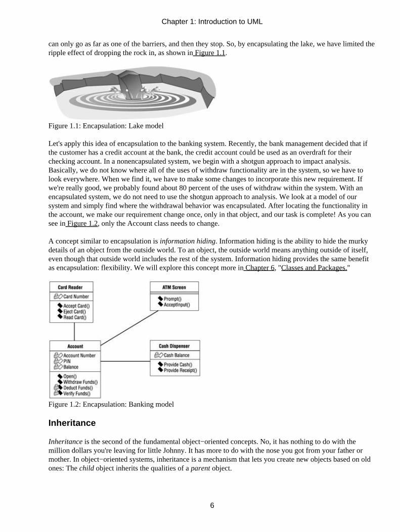
can only go as far as one of the barriers, and then they stop. So, by encapsulating the lake, we have limited theripple effect of dropping the rock in, as shown in Figure 1.1.
Figure 1.1: Encapsulation: Lake model
Let's apply this idea of encapsulation to the banking system. Recently, the bank management decided that ifthe customer has a credit account at the bank, the credit account could be used as an overdraft for theirchecking account. In a nonencapsulated system, we begin with a shotgun approach to impact analysis.Basically, we do not know where all of the uses of withdraw functionality are in the system, so we have tolook everywhere. When we find it, we have to make some changes to incorporate this new requirement. Ifwe're really good, we probably found about 80 percent of the uses of withdraw within the system. With anencapsulated system, we do not need to use the shotgun approach to analysis. We look at a model of oursystem and simply find where the withdrawal behavior was encapsulated. After locating the functionality inthe account, we make our requirement change once, only in that object, and our task is complete! As you cansee in Figure 1.2, only the Account class needs to change.
A concept similar to encapsulation is information hiding. Information hiding is the ability to hide the murkydetails of an object from the outside world. To an object, the outside world means anything outside of itself,even though that outside world includes the rest of the system. Information hiding provides the same benefitas encapsulation: flexibility. We will explore this concept more in Chapter 6, "Classes and Packages."
Figure 1.2: Encapsulation: Banking model
Inheritance
Inheritance is the second of the fundamental object−oriented concepts. No, it has nothing to do with themillion dollars you're leaving for little Johnny. It has more to do with the nose you got from your father ormother. In object−oriented systems, inheritance is a mechanism that lets you create new objects based on oldones: The child object inherits the qualities of a parent object.
Chapter 1: Introduction to UML
6

You can see examples of inheritance in the natural world. There are hundreds of different types of mammals:dogs, cats, humans, whales, and so on. Each of these has certain characteristics that are unique and certaincharacteristics that are common to the whole group, such as having hair, being warm−blooded, and nurturingtheir young. In object−oriented terms, there is a mammal object that holds the common characteristics. Thisobject is the parent of the child objects cat, dog, human, whale, etc. The dog object inherits the characteristicsof the mammal object, and has some additional dog characteristics of its own, such as running in circles andslobbering. The object−oriented paradigm has borrowed this idea of inheritance from the natural world, asshown in Figure 1.3, so we can apply the same concept to our systems.
Figure 1.3: Inheritance: Natural model
One of the major benefits of inheritance is ease of maintenance. When something changes that affects allmammals, only the parent object needs to change—the child objects will automatically inherit the changes. Ifmammals were suddenly to become cold−blooded, only the mammal object would need to change. The cat,dog, human, whale, and other child objects would automatically inherit the new, cold−blooded characteristicof mammals.
In an object−oriented system, an example of inheritance might be in the windows. Say we have a large systemwith 125 windows. One day, a customer requests a disclaimer message on all of the windows. In a systemwithout inheritance, we now have the rather tedious task of going into each one of the 125 windows andmaking the change. If our system were object−oriented, we would have inherited all of the windows from acommon parent. Now, all we need to do is go into the parent and make the change once. All of the windowswill automatically inherit the change, as shown in Figure 1.4.
Figure 1.4: Inheritance: Window model
In a banking system, we might use inheritance for the different types of accounts we have. Our hypotheticalbank has four different types of accounts: checking, savings, credit card, and certificates of deposit. Thesedifferent types of accounts have some similarities. Each one has an account number, interest rate, and owner.So, we can create a parent object called account to hold the common characteristics of all the accounts. Thechild objects can have their own unique characteristics in addition to the inherited ones. The credit account,for example, will also have a credit limit and minimum payment amount. The certificate of deposit will alsohave a maturity date. Changes to the parent will affect all children, but the children are free to adapt without
Chapter 1: Introduction to UML
7

disturbing each other or their parents.
Polymorphism
The third principle of object orientation is polymorphism. The dictionary defines it as the occurrence ofdifferent forms, stages, or types. Polymorphism means having many forms or implementations of a particularfunctionality. As with inheritance, polymorphism can be seen in the natural world. Given the command, orfunction, of "Speak!" a human may reply, "How do you do?" The dog may reply "Woof!" The cat may reply"Meow!" but will probably just ignore you.
In terms of an object−oriented system, this means that we can have many implementations of a particularfunctionality. For example, we might be building a graphic drawing system. When the user wants to drawsomething, be it a line, circle, or rectangle, the system issues a draw command. The system is comprised ofmany types of shapes, each of which contains the behavior to draw itself. So, when the user wants to draw acircle, the circle object's draw command is invoked. By using polymorphism, the system figures out as it isrunning which type of shape is being drawn. Without polymorphism, the code for the draw function mightlook like this:
Function Shape.drawMe(){SWITCH Shape.TypeCase "Circle"Shape.drawCircle();Case "Rectangle"Shape.drawRectangle();Case "Line"Shape.drawLine();END SWITCH}
With polymorphism, the code for draw would just call a drawMe() function for the object being drawn, as inthis example:
Function draw(){Shape.drawMe();}
Each shape (circle, line, rectangle, etc.) would then have a drawMe() function to draw the particular shape.
One of the benefits of polymorphism, as with the other principles of object orientation, is ease of maintenance.What happens, for example, when the application now needs to draw a triangle? In the nonpolymorphic case,a new drawTriangle() function has to be added to the shape object. Also, the drawMe() function of the shapeobject has to be changed to accommodate the new type of shape. With polymorphism, we create a newtriangle object with a drawMe() function to draw itself. The draw() function that initiates the drawingoperation does not have to change at all.
What Is Visual Modeling?
If you were building a new addition to your house, you probably wouldn't start by just buying a bunch ofwood and nailing it together until it looks about right. Similarly, you'd be more than a little concerned if the
Chapter 1: Introduction to UML
8

contractor doing the job decided to "wing it" and work without plans. You'd want some blueprints to follow soyou can plan and structure the addition before you start working. Odds are, the addition will last longer thisway. You wouldn't want the whole thing to come crashing down with the slightest rain.
Models do the same thing for us in the software world. They are the blueprints for systems. A blueprint helpsyou plan an addition before you build it; a model helps you plan a system before you build it. It can help yoube sure the design is sound, the requirements have been met, and the system can withstand even a hurricane ofrequirement changes.
As you gather requirements for your system, you'll take the business needs of the users and map them intorequirements that your team can use and understand. Eventually, you'll want to take these requirements andgenerate code from them. By formally mapping the requirements to the code, you can ensure that therequirements are actually met by the code, and that the code can easily be traced back to the requirements.This process is called modeling. The result of the modeling process is the ability to trace the business needs tothe requirements to the model to the code, and back again, without getting lost along the way.
Visual modeling is the process of taking the information from the model and displaying it graphically using astandard set of graphical elements. A standard is vital to realizing one of the benefits of visual modeling:communication. Communication between users, developers, analysts, testers, managers, and anyone elseinvolved with a project is the primary purpose of visual modeling. You could accomplish this communicationusing nonvisual (textual) information, but on the whole, humans are visual creatures. We seem to be able tounderstand complexity better when it is displayed to us visually as opposed to written textually. By producingvisual models of a system, we can show how the system works on several levels. We can model theinteractions between the users and a system. We can model the interactions of objects within a system. Wecan even model the interactions between systems, if we so desire.
After creating these models, we can show them to all interested parties, and those parties can glean theinformation they find valuable from the model. For example, users can visualize the interactions they willmake with the system from looking at a model. Analysts can visualize the interactions between objects fromthe models. Developers can visualize the objects that need to be developed and what each one needs toaccomplish. Testers can visualize the interactions between objects and prepare test cases based on theseinteractions. Project managers can see the whole system and how the parts interact. And chief informationofficers can look at high−level models and see how systems in their organization interact with one another.All in all, visual models provide a powerful tool for showing the proposed system to all of the interestedparties.
Systems of Graphical Notation
One important consideration in visual modeling is what graphical notation to use to represent various aspectsof a system. This notation needs to be conveyed to all interested parties or the model will not be very useful.Many people have proposed notations for visual modeling. Some of the popular notations that have strongsupport are Booch, Object Modeling Technology (OMT), and UML.
Rational Rose supports these three notations; however, UML is a standard that has been adopted by themajority of the industry as well as the standards' governing boards such as ANSI and the Object ManagementGroup (OMG).
Chapter 1: Introduction to UML
9

Booch Notation
The Booch method is named for its inventor, Grady Booch, at Rational Software Corporation. He has writtenseveral books discussing the needs and benefits of visual modeling, and has developed a notation of graphicalsymbols to represent various aspects of a model. For example, objects in this notation are represented byclouds, illustrating the fact that objects can be almost anything. Booch's notation also includes various arrowsto represent the types of relationships between objects. We will discuss these types of objects andrelationships in Chapter 4, "Use Cases and Actors." Figure 1.5 is a sampling of the objects and relationshipsrepresented in the Booch notation.
Figure 1.5: Examples of symbols in the Booch notation
Object Management Technology (OMT)
The OMT notation comes from Dr. James Rumbaugh, who has written several books about systems analysisand design. In an aptly titled book, Object−Oriented Modeling and Design (Prentice Hall, 1990), Rumbaughdiscusses the importance of modeling systems in real−world components called objects. OMT uses simplergraphics than Booch to illustrate systems. A sampling of the objects and relationships represented in the OMTnotation follows in Figure 1.6.
Chapter 1: Introduction to UML
10

Figure 1.6: Examples of symbols in the OMT notation
Unified Modeling Language (UML)
UML notation comes from a collaborative effort of Grady Booch, Dr. James Rumbaugh, Ivar Jacobson,Rebecca Wirfs−Brock, Peter Yourdon, and many others. Jacobson is a scholar who has written aboutcapturing system requirements in packages of transactions called use cases. We will discuss use cases in detailin Chapter 4. Jacobson also developed a method for system design called Object−Oriented SoftwareEngineering (OOSE) that focused on analysis. Booch, Rumbaugh, and Jacobson, commonly referred to as the"three amigos," all work at Rational Software Corporation and focus on the standardization and refinement ofUML. UML symbols closely match those of the Booch and OMT notations, and also include elements fromother notations. Figure 1.7 shows a sample of UML notation.
Chapter 1: Introduction to UML
11

Figure 1.7: Examples of symbols in UML notation
The consolidation of methods that became UML started in 1993. Each of the three amigos of UML began toincorporate ideas from the other methodologies. Official unification of the methodologies continued until late1995, when version 0.8 of the Unified Method was introduced. The Unified Method was refined and changedto the Unified Modeling Language in 1996. UML 1.0 was ratified and given to the Object Technology Groupin 1997, and many major software development companies began adopting it. In 1997, OMG released UML1.1 as an industry standard.
Over the past years, UML has evolved to incorporate new ideas such as web−based systems and datamodeling. The latest release is UML 1.3, which was ratified in 2000. The specification for UML 1.3 can befound at the Object Management Group's website, http://www.omg.org/. UML 1.3 is the version used in thisbook.
Understanding UML Diagrams
UML allows people to develop several different types of visual diagrams that represent various aspects of thesystem. Rational Rose supports the development of the majority of these models, as follows:
• Business Use Case diagram
• Use Case diagram
• Activity diagram
•
Chapter 1: Introduction to UML
12

Sequence diagram
• Collaboration diagram
• Class diagram
• Statechart diagram
• Component diagram
• Deployment diagram
These model diagrams illustrate different aspects of the system. For example, the Collaboration diagramshows the required interaction between the objects in order to perform some functionality of the system. Eachdiagram has a purpose and an intended audience.
Business Use Case Diagrams
Business Use Case diagrams are used to represent the functionality provided by an organization as a whole.They answer the questions "What does the business do?" and "Why are we building the system?" They areused extensively during business modeling activities to set the context for the system and to form a foundationfor creating the use cases. An example of a simplified Business Use Case diagram for a financial institution isshown in Figure 1.8.
Figure 1.8: Business Use Case diagram for a financial institution
Business Use Case diagrams are drawn from the organizational perspective. They do not differentiate betweenmanual and automated processes. (Use Case diagrams, which will be discussed next, focus on the automatedprocesses.) Business Use Case diagrams show the interactions between business use cases and business actors.Business use cases represent the processes that a business performs, and business actors represent roles withwhich the business interacts, such as customers or vendors. In other words, business actors represent anyone
Chapter 1: Introduction to UML
13

or anything outside the business that interacts with the business; they do not represent roles or workers withina business. Workers within a business are represented by business workers, which are discussed in Chapter 3,"Business Modeling."
Use Case Diagrams
Use Case diagrams show the interactions between use cases and actors. Use cases represent systemfunctionality, the requirements of the system from the user's perspective. Actors represent the people orsystems that provide or receive information from the system; they are among the stakeholders of a system.Use Case diagrams, therefore, show which actors initiate use cases; they also illustrate that an actor receivesinformation from a use case. In essence, a Use Case diagram can illustrate the requirements of the system.
While Business Use Case diagrams are not concerned with what is automated, Use Case diagrams focus onjust the automated processes. There is not a one−to−one relationship between business use cases and usecases. A single business use case may require 30 use cases, for example, to implement the process. Anexample of a Use Case diagram for an Automated Teller Machine (ATM) system is shown in Figure 1.9.
Figure 1.9: Use Case diagram for an Automated Teller Machine (ATM) system
This Use Case diagram shows the interactions between the use cases and actors of an ATM system. In thisexample, the bank's customer initiates a number of use cases: Withdraw Money, Deposit Funds, TransferFunds, Make Payment, View Balance, and Change PIN. A few of the relationships are worthy of furthermention. The bank officer can also initiate the Change PIN use case. The Make Payment use case shows anarrow going to the credit system. External systems may be actors and, in this case, the credit system is shownas an actor because it is external to the ATM system. The arrow going from a use case to an actor illustratesthat the use case produces some information that an actor uses. In this case, the Make Payment use caseprovides credit card payment information to the credit system.
Much information can be gleaned from viewing Use Case diagrams. This one diagram shows the overallfunctionality of the system. Users, project managers, analysts, developers, quality assurance engineers, andanyone else interested in the system as a whole can view these diagrams and understand what the system issupposed to accomplish.
Activity Diagrams
Activity diagrams illustrate the flow of functionality in a system. They may be used in business modeling toshow the business workflow. They may be used in requirements gathering to illustrate the flow of eventsthrough a use case. These diagrams define where the workflow starts, where it ends, what activities occur
Chapter 1: Introduction to UML
14

during the workflow, and in what order the activities occur. An activity is a task that is performed during theworkflow.
The structure of an activity diagram is similar to a Statechart diagram, which we will discuss later in thischapter. An example of an activity diagram is shown in Figure 1.10. The activities in the diagram arerepresented by rounded rectangles. These are the steps that occur as you progress through the workflow.Objects that are affected by the workflow are represented by squares. There is a start state, which representsthe beginning of the workflow, and an end state, which represents the end. Decision points are represented bydiamonds.
Figure 1.10: Activity diagram for opening an account
You can see the object flow through the diagram by examining the dashed lines. The object flow shows youwhich objects are used or created by an activity and how the object changes state as it progresses through theworkflow. The solid lines, known as transitions, show how one activity leads to another in the process. Ifneeded, you can place greater detail on the transitions, describing the circumstances under which the transitionmay or may not occur and what actions will be taken during the transition.
The activity diagram may be divided into vertical swimlanes. Each swimlane represents a different role withinthe workflow. By looking at the activities within a given swimlane, you can find out the responsibility of thatrole. By looking at the transitions between activities in different swimlanes, you can find out who needs tocommunicate with whom. All of this is very valuable information when trying to model or understand thebusiness process.
Activity diagrams do not need to be created for every workflow, but they are powerful communication tools,especially with large and complex workflows.
Chapter 1: Introduction to UML
15

Sequence Diagrams
Sequence diagrams are used to show the flow of functionality through a use case. For example, the WithdrawMoney use case has several possible sequences, such as withdrawing money, attempting to withdraw withoutavailable funds, attempting to withdraw with the wrong PIN, and several others. The normal scenario ofwithdrawing $20 (without any problems such as entering the wrong PIN or insufficient funds in the account)is shown in Figure 1.11.
Figure 1.11: Sequence diagram for Joe withdrawing $20
This Sequence diagram shows the flow of processing through the Withdraw Money use case. Any actorsinvolved are shown at the top of the diagram; the customer actor is shown in the above example. The objectsthat the system needs in order to perform the Withdraw Money use case are also shown at the top of thediagram. Each arrow represents a message passed between actor and object or object and object to perform theneeded functionality. One other note about Sequence diagrams—they display objects, not classes. Classesrepresent types of objects, as we'll discuss later in Chapter 5, "Object Interaction." Objects are specific;instead of just customer, the Sequence diagram shows Joe.
The use case starts with the customer inserting his card into the card reader, an object indicated by therectangle at the top of the diagram. Then, the card reader reads the card number, opens Joe's account object,and initializes the ATM screen. The screen prompts Joe for his PIN. He enters 1234. The screen verifies thePIN with the account object and they match. The screen presents Joe with his options, and he chooseswithdraw. The screen then prompts Joe for the amount to withdraw. He chooses $20. Then, the screenwithdraws the funds from the account. This initiates a series of processes that the account object performs.First, Joe's account verifies that the account contains at least $20. Then, it deducts the funds from the account.Next, it instructs the cash dispenser to provide $20 in cash. Joe's account also instructs the dispenser toprovide a receipt. Lastly, it instructs the card reader to eject the card.
This Sequence diagram illustrated the entire flow of processing for the Withdraw Money use case by showinga specific example of Joe withdrawing $20 from his account. Users can look at these diagrams to see thespecifics of their business processing. Analysts see the flow of processing in the Sequence diagrams.Developers see objects that need to be developed and operations for those objects. Quality assurance
Chapter 1: Introduction to UML
16

engineers can see the details of the process and develop test cases based on the processing. Sequence diagramsare therefore useful for all stakeholders in the project.
Collaboration Diagrams
Collaboration diagrams show exactly the same information as the Sequence diagrams. However,Collaboration diagrams show this information in a different way and with a different purpose. The Sequencediagram illustrated in Figure 1.11 is shown in Figure 1.12 as a Collaboration diagram.
Figure 1.12: Collaboration diagram for Joe withdrawing $20
In this Collaboration diagram, the objects are represented as rectangles and the actors are stick figures, asbefore. Whereas the Sequence diagram illustrates the objects and actor interactions over time, theCollaboration diagram shows the objects and actor interactions without reference to time. For example, in thisdiagram, we see that the card reader instructs Joe's account to open and Joe's account instructs the card readerto eject the card. Also, objects that directly communicate with each other are shown with lines drawn betweenthem. If the ATM screen and cash dispenser directly communicated with one another, a line would be drawnbetween them. The absence of a line means that no communication occurs directly between those two objects.
Collaboration diagrams, therefore, show the same information as Sequence diagrams, but people look atCollaboration diagrams for different reasons. Quality assurance engineers and system architects look at theseto see the distribution of processing between objects. Suppose that the Collaboration diagram was shaped likea star, with several objects communicating with a central object. A system architect may conclude that thesystem is too dependent on the central object and redesign the objects to distribute the processing power moreevenly. This type of interaction would have been difficult to see in a Sequence diagram.
Class Diagrams
Class diagrams show the interactions between classes in the system. Classes can be seen as the blueprint forobjects, as we'll discuss in Chapter 5. Joe's account, for example, is an object. An account is a blueprint forJoe's checking account; an account is a class. Classes contain information and behavior that acts on thatinformation. The Account class contains the customer's PIN and behavior to check the PIN. A class on a Classdiagram is created for each type of object in a Sequence or Collaboration diagram. The Class diagram for thesystem's Withdraw Money use case is illustrated in Figure 1.13.
Chapter 1: Introduction to UML
17

Figure 1.13: Class diagram for the ATM system's Withdraw Money use case
The Class diagram above shows the relationships between the classes that implement the Withdraw Moneyuse case. This is done with four classes: Card Reader, Account, ATM Screen, and Cash Dispenser. Each classon a Class diagram is represented by a rectangle divided into three sections. The first section shows the classname. The second section shows the attributes the class contains. An attribute is a piece of information that isassociated with a class. For example, the Account class contains three attributes: Account Number, PIN, andBalance. The last section contains the operations of the class. An operation is some behavior that the classwill provide. The Account class contains four operations: Open, Withdraw Funds, Deduct Funds, and VerifyFunds.
The lines connecting classes show the communication relationships between the classes. For instance, theAccount class is connected with the ATM Screen class because the two directly communicate with each other.The Card Reader is not connected to the Cash Dispenser because the two do not communicate. Another pointof interest is that some attributes and operations have small padlocks to the left of them. The padlock indicatesa private attribute or operation. Private attributes and operations can only be accessed from within the classthat contains them. The Account Number, PIN, and Balance are all private attributes of the Account class. Inaddition, the Deduct Funds and Verify Funds operations are private to the Account class.
Developers use Class diagrams to actually develop the classes. Tools such as Rose generate skeletal code forclasses, then developers flesh out the details in the language of their choice. Analysts use Class diagrams toshow the details of the system. Architects also look at Class diagrams to see the design of the system. If oneclass contains too much functionality, an architect can see this in the Class diagram and split out thefunctionality into multiple classes. Should no relationship exist between classes that communicate with eachother, an architect or developer can see this too. Class diagrams should be created to show the classes thatwork together in each use case, and comprehensive diagrams containing whole systems or subsystems can becreated as well.
Statechart Diagrams
Statechart diagrams provide a way to model the various states in which an object can exist. While the Classdiagrams show a static picture of the classes and their relationships, Statechart diagrams are used to model themore dynamic behavior of a system. These types of diagrams are extensively used in building real−timesystems. Rose can even generate the full code for a real−time system from the Statechart diagrams.
A Statechart diagram shows the behavior of an object. For example, a bank account can exist in severaldifferent states. It can be open, closed, or overdrawn. An account may behave differently when it is in each of
Chapter 1: Introduction to UML
18

these states. Statechart diagrams are used to show this information. Figure 1.14 shows an example of aStatechart diagram for a bank account.
Figure 1.14: Statechart diagram for the Account class
In this diagram, we can see the states in which an account can exist. We can also see how an account movesfrom one state to another. For example, when an account is open and the customer requests the account'sclosure, the account moves to the closed state. The customer's request is called the event and the event is whatcauses a transition from one state to another.
If the account is open and the customer makes a withdrawal, the account may move to the overdrawn state.This will only happen if the balance of the account is less than zero. We show this by placing [Balance < 0] onthe diagram. A condition enclosed in square brackets is called a guard condition, and controls when atransition can or cannot occur.
There are two special states—the start state and the stop state. The start state is represented by a black dot onthe diagram, and indicates what state the object is in when it is first created. The stop state is represented by abull's−eye, and shows what state the object is in just before it is destroyed. On a Statechart diagram, there isone and only one start state. On the other hand, you can have no stop state, or there can be as many stop statesas you need.
Certain things may happen when the object is inside a particular state. In our example, when an account isoverdrawn, a notice is sent to the customer. Processes that occur while an object is in a certain state are calledactions.
Statechart diagrams aren't created for every class; they are used only for very complex classes. If an object ofthe class can exist in several states, and behaves very differently in each of the states, you may want to createa Statechart diagram for it. Many projects won't need these diagrams at all. If they are created, developers willuse them when developing the classes.
Statechart diagrams are created for documentation only. When you generate code from your Rose model, nocode will be generated from the information on the Statechart diagrams. However, Rose add−ins are availablefor real−time systems that can generate executable code based on Statechart diagrams.
Component Diagrams
Component diagrams show you a physical view of your model, as well as the software components in yoursystem and the relationships between them. There are two types of components on the diagram: executable
Chapter 1: Introduction to UML
19

components and code libraries.
In Rose, each of the classes in the model is mapped to a source code component. Once the components havebeen created, they are added to the Component diagram. Dependencies are then drawn between thecomponents. Component dependencies show the compile−time and run−time dependencies between thecomponents. Figure 1.15 illustrates one of the Component diagrams for the ATM system.
Figure 1.15: Component diagram for the ATM client
This Component diagram shows the client components in the ATM system. In this case, the team decided tobuild the system using C++. Each class has its own header and body file, so each class is mapped to its owncomponents in the diagram. For example, the ATM Screen class is mapped to the ATM Screen component.The ATM Screen class is also mapped to a second ATM Screen component. These two components representthe header and body of the ATM Screen class. The shaded component is called a package body. It representsthe body file (.cpp) of the ATM Screen class in C++. The unshaded component is called a packagespecification. The package specification represents the header (.h) file of the C++ class. The component calledATM.exe is a task specification and represents a thread of processing. In this case, the thread of processing isthe executable program.
Components are connected by dashed lines showing the dependency relationships between them. Forexample, the Card Reader class is dependent upon the ATM Screen class. This means that the ATM Screenclass must be available in order for the Card Reader class to compile. Once all of the classes have beencompiled, then the executable called ATMClient.exe can be created.
The ATM example has two threads of processing and therefore two executables. One executable comprisesthe ATM client, including the Cash Dispenser, Card Reader, and ATM Screen. The second executablecomprises the ATM server, including the Account component. The Component diagram for the ATM server isshown in Figure 1.16.
Figure 1.16: Component diagram for the ATM server
Chapter 1: Introduction to UML
20

As this example shows, there can be multiple Component diagrams for a system, depending on the number ofsubsystems or executables. Each subsystem is a package of components. In general, packages are collectionsof objects. In this case, packages are collections of components. The ATM example includes two packages:the ATM client and the ATM server. Packages will be discussed more in Chapter 3.
Component diagrams are used by whoever is responsible for compiling the system. The diagrams will tell thisindividual in what order the components need to be compiled. The diagrams will also show what run−timecomponents will be created as a result of the compilation. Component diagrams show the mapping of classesto implementation components. These diagrams are also where code generation is initiated.
Deployment Diagrams
Deployment diagrams are the last type of diagram we will discuss. The Deployment diagram shows thephysical layout of the network and where the various components will reside. In our ATM example, the ATMsystem comprises many subsystems running on separate physical devices, or nodes. The Deployment diagramfor the ATM system is illustrated in Figure 1.17.
Figure 1.17: Deployment diagram for the ATM system
This Deployment diagram tells us much about the layout of the system. The ATM client executable will runon multiple ATMs located at different sites. The ATM client will communicate over a private network withthe regional ATM server. The ATM server executable will run on the regional ATM server. The regionalATM server will, in turn, communicate over the local area network (LAN) with the banking database serverrunning Oracle. Lastly, a printer is connected to the regional ATM server.
So, this one diagram shows us the physical setup for the system. Our ATM system will be following athree−tier architecture with one tier each for the database, regional server, and client.
The Deployment diagram is used by the project manager, users, architect, and deployment staff to understandthe physical layout of the system and where the various subsystems will reside. This diagram helps the projectmanager communicate what the system will be like to the users. It also helps the staff responsible fordeployment to plan their deployment efforts.
All of these diagrams together describe the system from several different perspectives. In Chapter 3, we willdiscuss each of these diagrams more closely and show how they are generated in Rational Rose. You will alsobe given the opportunity to try creating and using these diagrams in Rational Rose. But before we get into the
Chapter 1: Introduction to UML
21

details of Rose, another aspect of software development projects deserves some attention—the process. Whilethis is not a methodology or process book, we do want to familiarize you with a process for developmentusing UML diagrams we have discussed.
Visual Modeling and the Software Development Process
Software development can be done in many ways. There are several different types of development processesthat projects follow, including everything from the waterfall model to object−oriented processes. Each has itsbenefits and disadvantages. In this section, we do not plan to tell you which one to use, but we will present anoverview of a process that focuses on visual modeling. Again, this is just an overview.
For a long time, software development followed the waterfall model. In this model, we analyzed therequirements, designed a system, developed the system, tested the system, and deployed the system. As itsname suggests, we didn't flow back up this chain—water cannot go up. This method has been the documentedmethodology used on thousands of projects, but we contend that it has not been used as purely as we wouldlike to think. One of the main shortcomings of the waterfall model is that it is necessary to backtrack throughthe steps. At the outset of a project following the waterfall model, we take on the daunting task of determiningall of the system requirements. We do this through detailed discussions with the users and detailedexamination of business processes. After we're done, we make sure the users sign off on the voluminousrequirements we have written, even if they haven't read them yet. If we're really lucky, we might get about 80percent of the requirements of the system during this analysis stage.
Then, it's on to design. We sit down and determine the architecture of our system. We address issues such aswhere programs will reside and what hardware is necessary for acceptable performance. While doing this, wemay find out that some new issues have arisen. We then go back to the users and talk about the issues. Theseresult in new requirements. So, we're back in analysis. After going back and forth a few times, we move todevelopment and begin coding the system.
While coding, we discover that a certain design decision is impossible to implement, so we go back to designand revisit the issue. After coding is done, testing begins. While testing, we learn that a requirement was notdetailed enough and the interpretation was incorrect. Now we have to go back to the analysis phase and revisitthe requirement.
After some time, we finally finish the system and deliver it to the users. Since it took quite awhile and thebusiness has probably changed while we were building the system, the users respond less than enthusiasticallywith, "That's just what I asked for, but not what I want!" This incantation by the users is a powerful spell thatcauses the entire project team to age 10 years immediately!
So, after looking at this dismal scenario and wondering if you are in the right industry, what can you do tomake it better? Is the problem that the business changes so quickly? Is it that the users don't communicatewhat they want? Is it that the users don't understand the project team? Is it that the team didn't follow aprocess? The answers are yes, yes, yes, and no. The business changes very rapidly, and as softwareprofessionals we need to keep up. The users do not always communicate what they want because what they dois second nature to them. Asking an accounting clerk who has been on the job for 30 years is roughly likeasking someone how you breathe. It becomes so second nature that it is difficult to describe. Another problemis that the users don't always understand the project team. The team shows them flowcharts and producesvolumes of requirements text, but the users don't always understand what is being given to them. Can youthink of a way around this problem? Visual modeling can help. Lastly, the team did follow a process: the
Chapter 1: Introduction to UML
22

waterfall method (illustrated in Figure 1.18). Unfortunately, the plan and the execution of the method weretwo different things.
Figure 1.18: Waterfall method
One of the problems is that the team planned to use the waterfall method, with its neat and orderly passagethrough the stages of the project, but they had to backtrack throughout the project. Is this due to poorplanning? Probably not. Software development is a complex process and trying to do everything in neat stagesdoesn't always work. If the need for backtracking had been ignored, then the system would have design flaws,missing requirements, and possibly worse.
But over the years we have learned to plan the backtracking. With this insight comes iterative development.Iterative development just means that we are going to do things over and over. In the object−oriented process,we will go through the steps of analysis, design, development, testing, and deployment in small stages manytimes (illustrated in Figure 1.19). There are many different implementations of iterative lifecycles. One suchimplementation is the Rational Unified Process (RUP), which we will discuss briefly here. Please note thatthis book does not explore the details of RUP. For more details, please see Rational's website athttp://www.rational.com/.
Figure 1.19: Iterative method
It is impossible to learn all of the requirements during the early part of the project. New things are bound tocome out, so we plan for them by planning the project in iterations. With this concept, a project can be seen asa series of small waterfalls. Each one is designed to be big enough to mark the completion of an importantpart of the project, but small enough to minimize the need for backtracking.
In the project, we go through four phases: inception, elaboration, construction, and transition. Inception is thebeginning of the project. We gather information and do proofs−of−concept. At the end of inception is ago/no−go decision for the project. (A tenet of the Unified Process is a go/no−go decision at the end of eachphase.) In elaboration, use cases are detailed and architectural decisions are made. Elaboration includes someanalysis, design, coding, and test planning. Construction is where the bulk of the coding is done. Transition isthe final preparation and deployment of the system to the users. Next, we will discuss what each of thesephases means in an object−oriented project.
Chapter 1: Introduction to UML
23

Inception
The inception phase is the beginning of the project. Inception begins when someone says, "Gee, wouldn't it begreat if we had a system to do…?" Then, someone researches the idea and management asks how long itwould take, how much it will cost, or how feasible the project is. Finding out the answers to these questions iswhat the inception phase is all about.
We begin this phase with business modeling. During this process, we analyze the business around theproposed system. We discover what the high−level features of the system are and document them. We createbusiness use cases, business actors, and Business Use Case diagrams. (We do not go into details about the usecases here, but provide just a sentence or two.) We may also create activity diagrams to model the workflow.Armed with this information, we then move on to analyze the system to be developed. We also provideestimates to upper management. So, using Rose to support our project, we will create actors and use cases andproduce Use Case diagrams. Inception ends when the research is done and management commits theresources to work on the elaboration phase.
One more task remains in inception—the development of an iteration plan. An iteration plan is a plandescribing which use cases will be implemented during which iterations. If we find 10 use cases duringinception, we may draw up an iteration plan like this:
Iteration One Use Cases 1, 5, 6
Iteration Two Use Cases 7, 9
Iteration Three Use Cases 2, 4, 8
Iteration Four Use Cases 3, 10The plan tells us which use cases will be done first. Determining this plan requires looking at dependenciesbetween use cases and planning accordingly. If Use Case 3 is required in order for Use Case 5 to work, thenthe plan described above is not feasible because Use Case 3 would be implemented during the fourth iteration,far after Use Case 5 is in the first iteration. We may have to adjust our plan to accommodate the dependencies.
Using Rose in Inception
The inception phase begins with business modeling. Rose can be used to build the Business Use Case model,including business use cases, business actors, and business workers. The next step involves determining whatuse cases and actors are needed. Rose can be used to document these use cases and actors, and to create thediagrams to show their relationships. The Use Case diagrams can be presented to the users to validate that thediagrams are a comprehensive view of the system features.
Elaboration
The elaboration phase of the project includes some planning, analysis, and architectural design. Following theiteration plan, elaboration is done for each use case in the current iteration. Elaboration includes severalaspects of a project, such as coding proofs−of−concept, developing test cases, and making design decisions.The elaboration phase focuses on setting the architectural foundation for the project.
The major tasks in the elaboration phase are detailing the use cases. In Chapter 4, we will discuss what thedetails of a use case include. The low−level requirements of a use case include the flow of processing throughthe use case; what actors are involved with the use case; Sequence and Collaboration diagrams to show the
Chapter 1: Introduction to UML
24
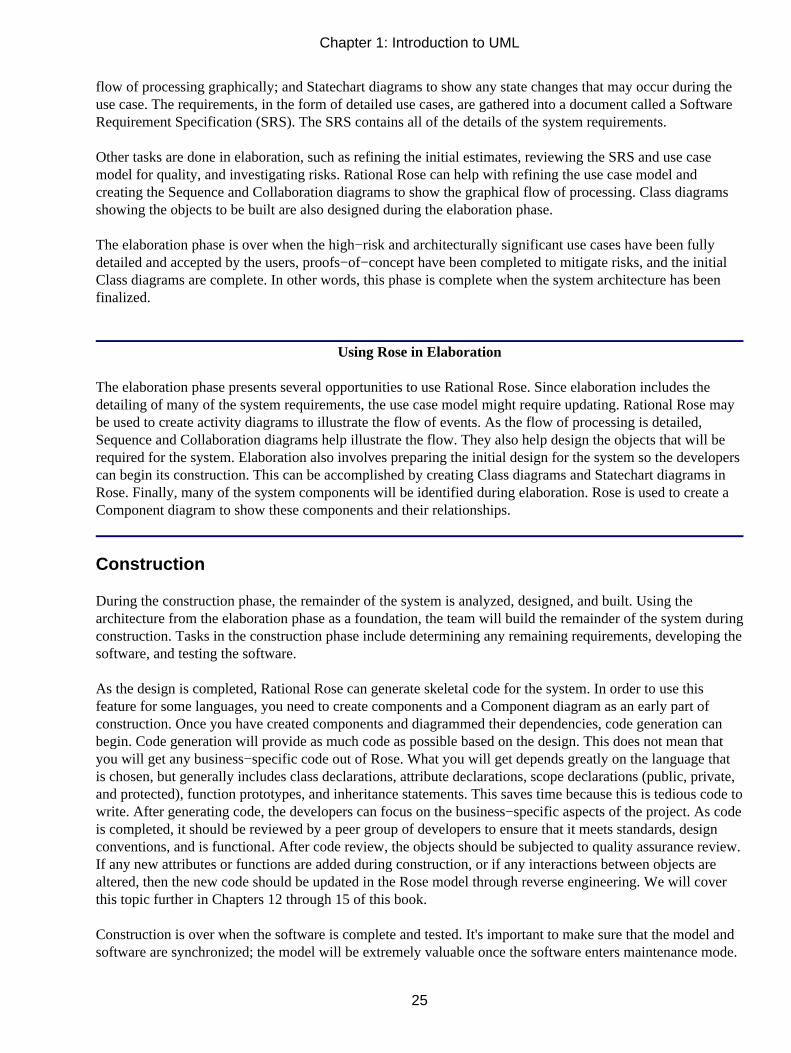
flow of processing graphically; and Statechart diagrams to show any state changes that may occur during theuse case. The requirements, in the form of detailed use cases, are gathered into a document called a SoftwareRequirement Specification (SRS). The SRS contains all of the details of the system requirements.
Other tasks are done in elaboration, such as refining the initial estimates, reviewing the SRS and use casemodel for quality, and investigating risks. Rational Rose can help with refining the use case model andcreating the Sequence and Collaboration diagrams to show the graphical flow of processing. Class diagramsshowing the objects to be built are also designed during the elaboration phase.
The elaboration phase is over when the high−risk and architecturally significant use cases have been fullydetailed and accepted by the users, proofs−of−concept have been completed to mitigate risks, and the initialClass diagrams are complete. In other words, this phase is complete when the system architecture has beenfinalized.
Using Rose in Elaboration
The elaboration phase presents several opportunities to use Rational Rose. Since elaboration includes thedetailing of many of the system requirements, the use case model might require updating. Rational Rose maybe used to create activity diagrams to illustrate the flow of events. As the flow of processing is detailed,Sequence and Collaboration diagrams help illustrate the flow. They also help design the objects that will berequired for the system. Elaboration also involves preparing the initial design for the system so the developerscan begin its construction. This can be accomplished by creating Class diagrams and Statechart diagrams inRose. Finally, many of the system components will be identified during elaboration. Rose is used to create aComponent diagram to show these components and their relationships.
Construction
During the construction phase, the remainder of the system is analyzed, designed, and built. Using thearchitecture from the elaboration phase as a foundation, the team will build the remainder of the system duringconstruction. Tasks in the construction phase include determining any remaining requirements, developing thesoftware, and testing the software.
As the design is completed, Rational Rose can generate skeletal code for the system. In order to use thisfeature for some languages, you need to create components and a Component diagram as an early part ofconstruction. Once you have created components and diagrammed their dependencies, code generation canbegin. Code generation will provide as much code as possible based on the design. This does not mean thatyou will get any business−specific code out of Rose. What you will get depends greatly on the language thatis chosen, but generally includes class declarations, attribute declarations, scope declarations (public, private,and protected), function prototypes, and inheritance statements. This saves time because this is tedious code towrite. After generating code, the developers can focus on the business−specific aspects of the project. As codeis completed, it should be reviewed by a peer group of developers to ensure that it meets standards, designconventions, and is functional. After code review, the objects should be subjected to quality assurance review.If any new attributes or functions are added during construction, or if any interactions between objects arealtered, then the new code should be updated in the Rose model through reverse engineering. We will coverthis topic further in Chapters 12 through 15 of this book.
Construction is over when the software is complete and tested. It's important to make sure that the model andsoftware are synchronized; the model will be extremely valuable once the software enters maintenance mode.
Chapter 1: Introduction to UML
25

Using Rose in Construction
As in the elaboration phase, Rose is used to create Sequence, Collaboration, Class, Statechart, and Componentdiagrams during construction. Rose is used to create components according to the object design. Componentdiagrams are created to show the compile−time dependencies between the components. After languages havebeen selected for each component, the generation of skeletal code can be done. After code has been created bythe developers, the model can be synchronized with the code through reverse engineering. Rose is also used inconstruction to create Deployment diagrams, which describe how the components are to be deployed.
Transition
The transition phase is when the completed software product is turned over to the user community. Tasks inthis phase include completing the final software product, completing final acceptance testing, completing userdocumentation, and preparing for user training. The Software Requirements Specification, Use Casediagrams, Class diagrams, Component diagrams, and Deployment diagrams must be updated to reflect anyfinal changes. It is important to keep these models synchronized with the software product because the modelswill be used once the software product goes into maintenance mode. Several months after the completion ofthe project, the models will be priceless in helping to make enhancements to the software.
Rose is used in the transition phase primarily to update the models as the software product is completed. Inparticular, updates to the Component and Deployment diagrams are common during the transition phase.
Summary
Visual modeling and Rational Rose are useful at several different stages of the software development process.Toward the beginning of the project, in inception, Rose is used to produce the business model and the use casemodel. During elaboration and construction, Rose is used extensively to develop activity diagrams showingthe flow of events. Sequence and Collaboration diagrams show the objects that will be developed and howthey interact with one another. Class diagrams are also developed in Rose, showing how the objects relate toeach other. Component diagrams are created using Rose to show the dependencies of the components in thesystem and to allow you to generate skeletal code for the system.
Throughout construction, we use Rose to reverse engineer newly developed code back into the model toincorporate any changes that arise during development. After construction, we move into transition, whereRose is used to update any of the models created during the project.
In the next chapter, we'll take a short tour of Rose. We'll examine the different features and capabilities of theRose tool, and talk about how to create and save a Rose model or elements of the model. We'll discuss how tonavigate Rose, the four views of the model that Rose provides, and how to publish your Rose model on theWeb.
Chapter 1: Introduction to UML
26

Chapter 2: A Tour of RoseThis chapter concludes our introduction to UML and Rose. After reading this chapter, you will be armed withenough information to embark on learning the fundamentals of designing systems with Rose. In this chapter,we discuss what Rational Rose is and what a Rational Rose model includes, and then take you on a visualtour, discussing the various parts of the screen and how to navigate through the product. We'll discuss the fourviews of a system that are available through Rose and how to work with Rose. Finally, we'll look at how topublish a Rose model to the Web, and how to manage versions of a Rose model.
What Is Rose?
Rational Rose is a powerful visual modeling tool to aid in the analysis and design of object−oriented softwaresystems. It is used to model your system before you write any code, so you can be sure that the system isarchitecturally sound from the beginning. Using the model, you can catch design flaws early, while they arestill inexpensive to fix.
Rational Rose supports business modeling, helping you to understand the business around the system. It helpswith systems analysis by enabling you to design use cases and Use Case diagrams to show the systemfunctionality. It will let you design Interaction diagrams to show how the objects work together to provide theneeded functionality. Class diagrams can be created to show the classes in a system and how they relate toeach other. Component diagrams can be developed to illustrate how the classes map to implementationcomponents. Finally, a Deployment diagram can be produced to show the network design for the system.
A Rose model is a picture of a system from various perspectives. It includes all of the UML diagrams, actors,use cases, objects, classes, components, and deployment nodes in a system. It describes in great detail whatthe system will include and how it will work, so developers can use the model as a blueprint for the systembeing built.
A blueprint is a good analogy for a Rose model. Just as a house has a set of blueprints that let differentmembers of the construction crew see it from different perspectives (plumbing, electrical, and so on), a Rosemodel contains a number of different diagrams that let the project team see the system from differentperspectives (customer, designer, project manager, tester, and so on).
Having a blueprint ahead of time helps alleviate an age−old problem. The team has talked to the customersand documented the requirements. Now the developers are ready to code. One developer (we'll call him Bob)takes some of the requirements, makes certain design decisions, and writes some code. Jane, anotherdeveloper, takes some requirements, makes completely different design decisions, and writes some morecode.
This difference in programming style is perfectly natural; 20 developers given the same requirements maycode 20 different systems. The problem comes about when someone needs to understand or maintain thesystem. Without conducting detailed interviews with each of the developers, it's hard for anyone to see whatdesign decisions were made, what the pieces of the system are, or what the overall structure of the system is.Without a documented design, it's hard to be sure that the system you built is actually the system the users hadin mind.
Traditionally, we follow a process that looks like this:
27

The requirements are documented, but the design is inside Bob's brain, so no one other than Bob has a goodidea of the system structure. If Bob leaves, that information leaves with him. If you've ever been the onetaking over for Bob, you can appreciate how difficult it can be to understand a system with littledocumentation.
A Rose model gives us a process that looks like this:
Now the design is documented. We get rid of Bob (figuratively speaking, of course!) and replace ourdependency on him with a documented design. The developers can all gather to discuss the design decisionsbefore the code is written. You don't have to worry about everyone going off in a separate direction with thesystem design.
But the developers aren't the only ones to use the model:
• The entire team will use the Business Use Case diagrams to get an understanding of the businesssurrounding the system.
• Customers and project managers will use the Use Case diagrams to get a high−level view of thesystem and to agree on the project scope.
• Project managers will use the Use Case diagrams and documentation to break the project down intomanageable pieces.
• Analysts and customers will look at the use case documentation to see what functionality the systemwill provide.
• Technical writers will look at the use case documentation to begin to write the user manual andtraining plans.
• Analysts and developers will look at Sequence and Collaboration diagrams to see how the logic in thesystem will flow, the objects in the system, and the messages between the objects.
• Quality assurance staff will use the use case documentation and the Sequence and Collaborationdiagrams to get the information they need for testing scripts.
•
Chapter 2: A Tour of Rose
28

Developers will use the Class diagrams and Statechart diagrams to get a detailed view of the pieces ofthe system and how they relate.
• Deployment staff will use the Component and Deployment diagrams to see what executable files,DLL files, or other components will be created, and where these components will be deployed on thenetwork.
• The whole team will use the model to be sure the requirements are traced to the code, and that thecode can be traced back to the requirements.
Rose, therefore, is a tool meant to be used by the entire project team. It is a repository of scope, analysis, anddesign information that each team member can use to get the information they need.
In addition to the above, Rational Rose will help developers by generating skeletal code. It can do this for anumber of different languages available on the market, including C++, Ada, CORBA, Java, COM objects,Visual Basic, and XML. Further, Rose can reverse engineer code and create a model based on an existingsystem. Having a model in Rose for an existing application is very beneficial. When a change occurs to themodel, Rose can modify the code to incorporate the change. Similarly, when a change occurs in the code, youcan incorporate that change into the model automatically. These features help you keep the model and thecode synchronized, reducing the risk of having an outdated model.
Rose can also be extended using RoseScript, a programming language packaged with Rose. Using thisprogramming language, you can write code to automatically make changes to your model, create a report, orperform other tasks with your Rose model.
There are three different versions of Rose currently available:
• Rose Modeler, which allows you to create a model for your system, but will not support codegeneration or reverse engineering.
• Rose Professional, which allows you to generate code in one language.
• Rose Enterprise, which allows you to generate code for C++, Java, Ada, CORBA, Visual Basic,COM, Oracle8, and XML. A model can have components that are generated in different languages.
What 's New in Rose 2002
In the last several years, Rose has been enhanced to accommodate some of the newer UML notation anddiagrams. The following list includes the newest of the enhanced Rose features at the time of this writing:
• A main diagram for each package can now be selected.
• Items on a diagram can now be moved around using the arrow keys.
•
Chapter 2: A Tour of Rose
29

The Page Up and Page Down keys can now be used to scroll through a diagram.
• Default C++ component styles can be set.
• Directories and file extensions for C++ code generation can be specified.
• It includes support for Microsoft Interface Definition Library (MIDL) round−trip engineering.
• It includes support for J2EE deployment.
• It includes additional support for the reverse engineering of Enterprise JavaBeans (EJBs).
What's New in Rose 2001A
Some other new Rose features include:
• Business modeling, which was discussed briefly in Chapter 1, "Introduction to UML," focuses on theworld around the system, and helps to set the context for the use case model.
• Activity diagrams, which can be used to describe the workflow through a business use case or theflow of events through a use case.
• Support for ANSI C++, which will be discussed in detail in the code generation and reverseengineering section of this book. A model converter can be used to convert older Rose C++ models toRose ANSI C++ models.
• Tighter integration with Rational's ClearCase tool, which is used for version control.
• Enhanced data−modeling capabilities.
• Modeling, code generation, and reverse engineering of Enterprise Java Beans.
Getting Around in Rose
In the next few sections of this chapter, we'll describe each part of the Rose interface. Rose is largely amenu−driven application, with toolbars to help with commonly used features. Rose supports eight differenttypes of UML diagrams: Use Case diagrams, Activity diagrams, Sequence diagrams, Collaboration diagrams,
Chapter 2: A Tour of Rose
30

Class diagrams, Statechart diagrams, Component diagrams, and Deployment diagrams. Rose will present youwith a different toolbar for each of these diagrams. In the next nine chapters, we'll show you how to create allof these types of diagrams.
In addition to the toolbars and menus, Rose includes context−sensitive shortcut menus, visible byright−clicking an item. For example, right−clicking a class on a Class diagram will display a menu thatincludes options for adding attributes or operations to the class, viewing or editing the class specifications,generating code for the class, or viewing the generated code. When in doubt, right−click! Rose will almostalways give you helpful menu options.
One of the easiest ways to get around in Rose is to use the browser, which is the treeview on the left side ofthe screen. With the browser, you can quickly and easily get to the diagrams and other elements of the model.If you run into trouble while using Rose, press F1 at any time to access the extensive online help file.
Parts of the Screen
The five primary pieces of the Rose interface are the browser, the documentation window, the toolbars, thediagram window, and the log. In this section, we'll look at each of these. Briefly, their purposes are:
Browser Used to quickly navigate through the model
Documentation window Used to view or update documentation of model elements
Toolbars Used for quick access to commonly used commands
Diagram window Used to display and edit one or more UML diagrams
Log Used to view errors and report the results of various commands
Figure 2.1 illustrates the various parts of the Rose interface.
Figure 2.1: The Rose interface
Chapter 2: A Tour of Rose
31

Browser
The browser is a hierarchical structure you can use to easily navigate through your Rose model. Anything youadd to the model—actors, use cases, classes, components, and so on—will display in the browser. Thebrowser is shown in Figure 2.2.
Figure 2.2: Rose browser
Using the browser, you can
• Add model elements (use cases, actors, classes, components, diagrams, etc.)
• View existing model elements
• View existing relationships between model elements
• Move model elements
• Rename model elements
•
Chapter 2: A Tour of Rose
32

Add a model element to a diagram
• Attach a file or URL to an element
• Group elements into packages
• Access the detailed specifications of an element
• Open a diagram
There are four views in the browser: the Use Case view, the Logical view, the Component view, and theDeployment view. Table 2.1 lists each of these views and the model elements found in the views.
Table 2.1: Views in Rational Rose
View Contents
Use Case view Business actors
Business workers
Business use cases
Business Use Case diagrams
Business Use Case realizations
Actors
Use cases
Associations
Use case documentation
Use Case diagrams
Activity diagrams
Sequence diagrams
Collaboration diagrams
Packages
Logical view Classes
Chapter 2: A Tour of Rose
33

Class diagrams
Associations
Interfaces
Sequence diagrams
Collaboration diagrams
Statechart diagrams
Packages
Component view Components
Interfaces
Component diagrams
Packages
Deployment view Processes
Processors
Connectors
Devices
Deployment diagramUsing the browser, you can view the model elements in each of these four views, move or edit elements, oradd new elements. By right−clicking an element in the browser, you can attach files or URLs to the element,access the detailed specifications of the element, delete the element, or rename the element.
The browser is organized in a treeview style. Each model element may contain other elements beneath it inthe hierarchy.
By default, the browser will appear in the upper−left area of the screen. You can move the browser to anotherlocation or hide the browser altogether.
To show or hide the browser:
1. Right−click in the browser window.
2. Select Hide from the shortcut menu. Rose will show or hide the browser.
OR
Select View → Browser. Rose will show or hide the browser.
Chapter 2: A Tour of Rose
34

Documentation Window
The documentation window is used to document the elements of your Rose model. For example, you maywant to write a short definition for each of your actors. You can enter this definition using the documentationwindow, as shown in Figure 2.3.
Figure 2.3: The documentation window
When you add documentation to a class, anything you type in the documentation window will appear as acomment in the generated code, reducing the need to go in later and comment on the system's code. Thedocumentation will also appear in the reports you can generate from Rose.
As you select different elements from the browser or on a diagram, the documentation window willautomatically be updated to display the documentation for the selected element.
Toolbars
Rose toolbars provide you with quick access to commonly used commands. There are two toolbars in Rose:the Standard toolbar and the Diagram toolbar, which is called the toolbox. The Standard toolbar containsoptions you can use in any diagram. These options are shown in Table 2.2.The toolbox changes for each typeof UML diagram. The different Diagram toolbars will be discussed in detail in the remainder of this book.
Table 2.2: Icons in Standard Toolbar
Icon Button Purpose
Create New Model Creates a new Rose model (.mdl) file.
Open Existing Model Opens an existing Rose model (.mdl) file.
Save Model or Log Saves the Rose model (.mdl) file or the log for the current model.
Chapter 2: A Tour of Rose
35

Cut Moves text to the clipboard.
Copy Copies text to the clipboard.
Paste Pastes text from the clipboard.
Print Diagrams Prints one or more diagrams from the current model.
Context Sensitive Help Accesses the help file.
View Documentation Views the documentation window.
Browse Class Diagram Locates and opens a Class diagram.
Browse Interaction Diagram Locates and opens a Sequence or Collaboration diagram.
Browse Component Diagram Locates and opens a Component diagram.
Browse State Machine DiagramLocates and opens a Statechart diagram.
Browse Deployment Diagram Opens the Deployment diagram for the model.
Browse Parent Opens a diagram's parent diagram.
Browse Previous Diagram Opens the diagram you were most recently viewing.
Zoom In Increases the zoom.
Zoom Out Decreases the zoom.
Fit in Window Sets the zoom so the entire diagram fits within the window.
Undo Fit in Window Undoes the Fit in Window command.
All of the toolbars can be customized. To customize a toolbar, select Tools → Options, then select theToolbars tab.
To show or hide the Standard toolbar:
1. Select Tools → Options.
2. Select the Toolbars tab.
3. Use the Show Standard Toolbar check box to show or hide the Standard toolbar.
To show or hide the Diagram toolbar:
1. Select Tools → Options.
2. Select the Toolbars tab.
3. Use the Show Diagram Toolbar check box to show or hide the Diagram toolbar (toolbox).
To customize a toolbar:
1.
Chapter 2: A Tour of Rose
36

Right−click the desired toolbar.
2. Select the Customize option.
3. Add or remove buttons to customize the toolbar by selecting the appropriate button and then clickingthe Add or Remove button, as shown in Figure 2.4.
Figure 2.4: Customizing a toolbar
Diagram Window
In the diagram window shown in Figure 2.5, you can view UML diagrams in your model. As you makechanges to elements in a diagram, Rose will automatically update the browser as necessary. Similarly, whenyou make changes to an element using the browser, Rose will automatically update the appropriate diagrams.By doing so, Rose helps you maintain a consistent model.
Figure 2.5: Diagram window
Log
As you work on your Rose model, certain information will be posted to the log window. For example, whenyou generate code, any errors that are generated are posted in the log window, shown in Figure 2.6.
Chapter 2: A Tour of Rose
37

Figure 2.6: Log window
Exploring Four Views in a Rose Model
There are four views in a Rose model: the Use Case view, the Logical view, the Component view, and theDeployment view. Each of these four views addresses a different audience and purpose. In the followingsections, we'll take a brief look at each of these views. In the remainder of this book, we'll discuss the detailedmodel elements that appear in each of these views.
Use Case View
The Use Case view includes all of the actors, use cases, and Use Case diagrams in the system. It may alsoinclude some Sequence and Collaboration diagrams. The Use Case view is an implementation−independentlook at the system. It focuses on a high−level picture of what the system will do, without worrying about thedetails of how the system will do it. Figure 2.7 illustrates the Use Case view in the Rose browser.
Chapter 2: A Tour of Rose
38

Figure 2.7: Use Case view
The Use Case view includes:
Business use cases, which are workflows within the organization.
Business actors, which are people, companies, or other entities outside the organization who interactwith the business.
Business workers, which are roles within the organization
Organizational units, which are groups of business cases and/or business workers.
Activity diagrams, which are used to describe the workflow within a business use case or a flow ofevents through a use case.
Actors, which are external entities that interact with the system being built.
Use cases, which are high−level pieces of functionality the system will provide.
Use case documentation, which details the flow through the use case, including any error handling. Thisicon represents an external file that has been attached to your Rose model. The icon used will dependupon the application you used to document the flow of events. Here, we used Microsoft Word.
Use Case diagrams, which show the actors, the use cases, and the interactions between them. There aretypically several Use Case diagrams per system, each showing a subset of the actors and/or use cases.
Interaction diagrams, which display the objects or classes involved in one flow through a use case.There may be many Interaction diagrams for each use case. Interaction diagrams can be created in eitherthe Use Case view or the Logical view. Any Interaction diagrams that are implementation−independentare typically created in the Use Case view. Any Interaction diagrams that are language−specific arelocated in the Logical view.
Chapter 2: A Tour of Rose
39

Packages, which are groups of use cases, actors, or other modeling elements. A package is a UMLmechanism that helps you to group related items together. In most cases, there are few enough use casesand actors that packaging is not essential. However, it's a tool that is always available to help youorganize the Use Case view. In particular, it can be convenient to package these elements forconfiguration management.
When the project first begins, the team may optionally produce a business model in the Use Case view. If thistask is undertaken, the team members that will be needed include the customer, the project manager, andanalysts who focus on business processes (frequently termed business analysts). The rest of theteam—including designers, coders, testers, and so on—will refer to the business model throughout the projectto gain an understanding of the overall business and how the new system fits into its organizational structure.We will discuss the business model in more detail in Chapter 3, "Business Modeling."
Once the business model has been completed, the team moves on to the use case model. Customers, analysts,and project managers will work with the use cases, Use Case diagrams, and use case documentation to agreeon a high−level view of the system.
Note This view focuses only on what the system will do. Implementation details should be left for futurediscussions. In an object−oriented system, use cases are the system requirements.
As the project goes along, all members of the team can look at the Use Case view to get a high−levelunderstanding of the system being built. The use case documentation will describe the flow of events througha use case. With this information, quality assurance staff can begin to write testing scripts. Technical writerscan begin the user documentation. Analysts and customers can help ensure that all requirements werecaptured. Developers can see what high−level pieces of the system will be created, and how the system logicshould flow.
Once the customer has agreed to the use cases and actors, they have agreed to the system scope. Thedevelopment can then continue to the Logical view, which focuses more on how the system will implementthe behavior spelled out in the use cases.
Logical View
The Logical view, shown in Figure 2.8, focuses on how the system will implement the behavior in the usecases. It provides a detailed picture of the pieces of the system, and describes how the pieces interrelate. TheLogical view includes, among other things, the specific classes that will be needed, the Class diagrams, andthe Statechart diagrams. With these detailed elements, developers can construct a detailed design for thesystem.
Chapter 2: A Tour of Rose
40

Figure 2.8: Logical view
The Logical view includes:
Classes, which are the building blocks for a system. A class consists of a little bit of information(its attributes) and a little bit of behavior (its operations), grouped together. For example, anEmployee class might store information about the employee's name, address, and social securitynumber, and might include behavior such as hiring or firing an employee. There are different typesof icons that are used for different types of classes. We will discuss these further in Chapter 6,"Classes and Packages."
Class diagrams, which are used to view the classes in the system, their attributes and operations,and their relationships to each other. Typically, a system will have several Class diagrams, eachshowing a subset of all the classes.
Interaction diagrams, which include Sequence and Collaboration diagrams, are used to display theclasses that participate in one flow of events through a use case. As we mentioned above,Interaction diagrams can be created in either the Use Case view or the Logical view. Interactiondiagrams in the Use Case view tend to be high−level and implementation−independent, whileInteraction diagrams in the Logical view are more detailed.
Statechart diagrams, which show the dynamic behavior of an object. A Statechart diagramincludes all of the states in which a particular object can exist. It also illustrates how the objectmoves from one state to another, what state the object is in when it is first created, and what statethe object is in when it is destroyed. A Statechart diagram can be useful in detailing business rules.
Packages, which are groups of related classes or other modeling elements. Packaging isn'trequired, but it is certainly recommended. A typical system may have a hundred classes or more.Packaging your classes can help reduce the complexity of your model. To get a general picture ofthe system, you can look at the packages. To see a more detailed view, you can go into any of thepackages and view the classes inside.
Frequently, teams take a two−pass approach to the Logical view. In the first approach, they identify analysisclasses. Analysis classes are language−independent classes. By focusing first on analysis classes, the team canbegin to see the structure of the system without getting bogged down in the implementation−specific details.In UML, analysis classes can be represented using the following icons:
Chapter 2: A Tour of Rose
41

The analysis classes might also appear on some Interaction diagrams in the Use Case view. Once the analysisclasses have been identified, the team can change each one to a design class. A design class is a class that haslanguage−specific details. For example, we may have an analysis class that's responsible for talking to anothersystem. We don't worry about what language the class will be written in—we focus only on what informationand behavior it will have. When we turn it into a design class, however, we look at the language−specificdetails. We may decide that now we have a Java class. We might even decide that we need two Java classes toactually implement what we uncovered in analysis—there isn't necessarily a one−to−one mapping betweenanalysis classes and design classes. Design classes are shown on the Interaction diagrams that appear in theLogical view.
The focus of the Logical view is on the logical structure of the system. In this view, you identify the pieces ofthe system, examine the information and behavior of the system, and examine the relationships between thepieces. Reuse is one of the main considerations here. By carefully assigning information and behavior toclasses, grouping your classes together, and examining the relationships between the classes and the packages,you can identify classes and packages that can be reused. As you complete more and more projects, you canadd new classes and packages to a reuse library. Future projects then become more of a process of assemblingwhat you already have, rather than building everything from scratch.
Nearly everyone on the team will use information from the Logical view, but the primary users will be thedevelopers and architect. The developers will be concerned with what classes are created, what informationand behavior each class should have, and what relationships exist between the classes. The architect, who ismore concerned with the structure of the overall system, is responsible for ensuring that the system has astable architecture, that reuse has been considered, and that the system will be flexible enough to change asrequirements change. Analysts will look at the classes and Class diagrams to help ensure that the businessrequirements will be implemented in the code. Quality assurance staff will look at the classes, packages, andClass diagrams to see what pieces of the system exist and need to be tested. They will also use the Statechartdiagrams to see how a particular class should behave. The project manager will look at the classes anddiagrams to ensure that the system is well structured, and to get an estimate of how complex the system is.
Once you've identified the classes and diagrammed them, you can move on to the Component view, whichfocuses more on the physical structure.
Component View
The Component view contains information about the code libraries, executable files, run−time libraries, andother components in your model. A component is a physical module of code.
In Rose, components and Component diagrams are displayed in the Component view, as shown in Figure 2.9.The Component view of the system allows you to see the relationships between the modules of code.
Chapter 2: A Tour of Rose
42

Figure 2.9: Component view
The Component view includes:
Components, which are physical modules of code.
Component diagrams, which show the components and their relationships to each other.Relationships between the components let you know what the compilation dependencies are. Withthis information, you can determine the compilation order of the components.
Packages, which are groups of related components. As with packaging classes, reuse is one of theconsiderations when packaging components. A group of related components may be very easy topick up and reuse in other applications, so long as the relationships between the group and othergroups are carefully monitored. We'll discuss these issues in detail later.
The main users of the Component view are those people responsible for controlling the code and compilingand deploying the application. Some of the components will be code libraries. Others will be run−timecomponents, such as executable files or dynamic link library (DLL) files. Developers will also use theComponent view to see what code libraries have been created and which classes are contained in each codelibrary.
Deployment View
The final view in Rose is the Deployment view. The Deployment view is concerned with the physicaldeployment of the system, which may differ from the logical architecture of the system.
For example, the system may have a logical three−tier architecture. In other words, the interface may beseparated from the business logic, which is separated from the database logic. However, the deployment may
Chapter 2: A Tour of Rose
43

be two−tiered. The interface may be placed on one machine, while the business and database logic are locatedon another machine.
Other issues, such as fault tolerance, network bandwidth, disaster recovery, and response time, are alsohandled using the Deployment view. The Deployment view is shown in Figure 2.10.
Figure 2.10: Deployment view
The Deployment view includes:
Processes, which are threads that execute in their own memory space.
Processors, which include any machines with processing power. Each process will run on one ormore processors.
Devices, which include any hardware without processing power. Examples are dumb terminalsand printers.
A Deployment diagram shows the processes and devices on the network and the physical connectionsbetween them. The Deployment diagram will also display the processes, and show which processes run onwhich machines.
Again, the whole team will use the information in the Deployment view to understand how the system will bedeployed. However, the primary users will be the staff responsible for distributing the application.
Chapter 2: A Tour of Rose
44

Working with Rose
Everything you do in Rose relates to a model. In this section, we will discuss how to use models. We will firstlook at how to create and save Rose models. Then, we will discuss team design considerations by usingcontrolled units, and show you how to publish a Rose model to the Web.
Creating Models
The first step in working with Rose is to create a model. Models can be either created from scratch or madeusing an existing framework model. A Rose model and all diagrams, objects, and other model elements aresaved in a single file with the extension .mdl (model).
To create a model:
1. Select File → New from the menu, or press the New button on the Standard toolbar.
2. If the Framework Wizard is installed, then the list of available frameworks will be displayed, as inFigure 2.11. Select the framework you want to use and click OK, or click Cancel to use noframework.
Figure 2.11: Framework Wizard
If you select a framework, Rose will automatically load the default packages, classes, and components thatcome with that framework. For example, loading the J2EE framework provides default applet, beans, andother classes, as can be seen in Figure 2.12.
Chapter 2: A Tour of Rose
45

Figure 2.12: J2EE foundation
Although they cannot all be seen in the figure, the J2EE framework provides classes and interfaces withineach of the packages. Each one has the appropriate attributes and operations, so the team does not need tomanually enter them.
There are two benefits to using a framework:
• The team does not need to spend unnecessary time modeling elements that already exist. The focus ofthe modeling effort is on what's unique to a project, not reinventing existing components (althoughreusing them is fine!).
• A framework helps provide consistency across projects. As we mentioned in Chapter 1, a primarybenefit of modeling is ensuring consistency between team members or even between entire teams.Using the same framework in different projects ensures that both teams are building from the samefoundation.
Rose even gives you the option of creating your own framework. Using this approach, you collect and modelthe classes and components that form your organization's architectural foundation. Upon this foundation, youcan design and build multiple systems.
Saving Models
As with any other application, it is good practice to save the file periodically. Rose is no exception. Asmentioned above, the entire model is saved in one file. In addition, you can save the log to a file.
To save a model:
Chapter 2: A Tour of Rose
46
Select File → Save from the menu.
OR
Click the Save button on the Standard toolbar.
To save the log:
1. Select the log window.
2. Select File → Save Log As from the menu.
3. Enter the filename of the log.
OR
1. Select the log window.
2. Click the Save button on the Standard toolbar.
3. Enter the filename of the log.
Exporting and Importing Models
One of the main benefits of the object−oriented paradigm is reuse. Reuse can apply not only to the code but tothe models as well. To fully take advantage of reuse, Rose supports exporting and importing models andmodel elements. You can export a model or a portion of a model and import it into other models.
To export a model:
1. Select File → Export Model from the menu.
2. Enter the name of the export file.
To export a package of classes:
1. Select the package to export from a Class diagram.
2. Select File → Export <package> from the menu.
3.
Chapter 2: A Tour of Rose
47

Enter the name of the export file.
To export a class:
1. Select the class to export from a Class diagram.
2. Select File → Export <class> from the menu.
3. Enter the name of the export file.
To import a model, package, or class:
1. Select File → Import Model from the menu.
2. Select the file to import. Allowable file types are model (.mdl), petal (.ptl), category (.cat), orsubsystem (.sub).
Publishing Models to the Web
You can easily publish all or any part of your Rose model to the Web—either to an intranet, the Internet, or afilesystem site—using Rational Rose 2001A or 2002. This way, users who may need to view the model cando so without having Rose installed and without printing a ream of model documentation. A model publishedto the Web is shown in Figure 2.13.
Figure 2.13: ATM model on the Web
To publish a model to the Web:
1. Select Tools → Web Publisher from the menu.
2.
Chapter 2: A Tour of Rose
48

Select the model views and packages to publish from the Web Publisher window, as shown in theSelections field in Figure 2.14.
Figure 2.14: Web Publisher window
3. In the Level of Detail field, select the desired level of detail. The Documentation Only option includesonly high−level information; none of the properties of the model elements are displayed. TheIntermediate option displays the properties found on the General tab on model element specifications.The Full option publishes all properties, including those listed on the Detail tab on model elementspecifications.
4. Select the notation to use while publishing. Notation will default to the default notation in Rose.
5. Choose whether or not to publish inherited items.
6. Choose whether or not to publish properties.
7. Choose whether or not to publish associations, which are the relationships between model elements. Ifthis box is selected, associations will appear in the browser treeview.
8. Enter the name of the HTML root filename where the model will be published.
9. If you want to choose the graphic file format for the diagrams, select the Diagrams button. TheDiagram Options window will be displayed, as in Figure 2.15.
Chapter 2: A Tour of Rose
49

Figure 2.15: Diagram Options window
Select the type of graphic format to use while publishing diagrams: Windows bitmaps, PortableNetwork Graphics (PNGs), or JPEGs. You can also select to not publish diagrams.
10. When ready, click Publish. Rose will create all of the web pages to publish your model.
11. If desired, click Preview to see the published model.
Working with Controlled Units
Rose supports multiuser, parallel development through the use of controlled units. A controlled unit in Rosecan be any package within the Use Case view, Logical view, or Component view. In addition, the Deploymentview and the Model Properties units can also be placed under control. When a unit is controlled, all of themodel elements inside it are stored in a separate file from the rest of the model. This way, the separate file canbe controlled through the use of an SCC−compliant version control tool, such as Rational ClearCase orMicrosoft SourceSafe, or minimally within Rose directly. To create or manage a controlled unit, right−clickthe package to control and select the Units option, as shown in Figure 2.16.
Figure 2.16: Managing units
Follow these steps to create a controlled unit:
1. In the browser, right−click the package to be placed under control.
2.
Chapter 2: A Tour of Rose
50

Select Units → Control <package> from the menu.
3. Enter the filename for the controlled unit. Notice that the icon in the browser now has a page symbolon the folder to symbolize that the package is controlled.
In a parallel development environment, you may need to unload a package so that others can work on thepackage. You may only modify a loaded package. An unloaded package is available for others to load andmodify. To unload a controlled unit:
1. Right−click the package to be unloaded.
2. Select Units → Unload <package> from the menu. Notice that the items in the package are removedfrom the browser because they have been removed from the model.
To unload all controlled units in a view:
1. Right−click the view.
2. Select Units → Unload Subunits of <view> from the menu.
Periodically, you may want to reload a package that has just been updated by another development team. Toload a controlled unit:
1. Right−click the package to be reloaded.
2. Select Units → Reload <package> from the menu.
To uncontrol a controlled unit:
1. Make sure the controlled unit is loaded.
2. Right−click the package to be uncontrolled.
3. Select Units → Uncontrol <package> from the menu. Note that the controlled unit's file is not deletedfrom your computer.
At times, you may want to view certain items without modifying them. To protect from modifying controlledunits, mark the unit as write−protected.
To write−protect a controlled unit:
1.
Chapter 2: A Tour of Rose
51

Right−click the package to be write−protected.
2. Select Units → Write Protect <package> from the menu.
To write−enable a controlled unit:
1. Right−click the package to be write−enabled.
2. Select Units → Write Enable <package> from the menu.
Using the Model Integrator
The Model Integrator in Rose is a way to compare and merge up to seven Rose models. This feature isespecially useful in situations with multiple designers. Each can work individually, and then all models can beintegrated into one.
When comparing models, Rose will show you the differences between them. To begin, select Tools → ModelIntegrator from the menu. You will see the screen shown in Figure 2.17. If you do not see a Model Integratoroption on the Tools menu, select Add Ins → Add In Manager, and then select the Model Integrator.
Figure 2.17: The Model Integrator
To compare two or more Rose models:
1. Select File → Contributors from the menu.
2. Press the […] button to select the first model to compare.
3. Press the New button to add additional Rose models.
Chapter 2: A Tour of Rose
52

4. Select additional files as needed, until all files you wish to compare have been selected.
5. Press the Compare button. The differences will be displayed, as shown in Figure 2.18.
Figure 2.18: Model differences
6. Press the Merge button to merge rather than compare models. The Model Integrator will attempt tomerge the files for you. If there are any conflicts, you will see a message in the lower−right corner ofthe window informing you of the number of unresolved items. Use the Previous Conflict and NextConflict toolbar buttons to navigate to the conflicts and resolve them.
7. Once all conflicts are resolved, you may save the new model.
Working with Notes
A note is simply a small amount of text that you would like to add to a diagram. It can be related to the overalldiagram or to a particular element on the diagram. If it is related to a particular element, it is attached to thatelement, as shown in Figure 2.19.
Chapter 2: A Tour of Rose
53

Figure 2.19: Notes
To add a note to a diagram:
1. Select the Note icon from the toolbar.
2. Click anywhere inside the diagram to place the note.
3. Select the Anchor Note to Item button from the toolbar.
4. Drag and drop from the note to the item.
To remove a note from a diagram, simply select it and press the Delete key.
Working with Packages
A package is a UML construct that is used to group model elements together. You can create a package of usecases, actors, classes, or any other type of model element.
Packages are mainly used to organize the model. In the Use Case view, packages simply group the use casesand actors into more manageable views. In the Logical view, packages are used for two purposes:
• They can be used to group the classes and other model elements into logical groupings (i.e., all of theclasses that deal with orders, all of the classes that deal with customers, etc.).
• They can be used to show the physical deconstruction of the system into architectural layers. Forexample, one package may hold the user interface elements, while another holds the business logic,and still another holds the database connection classes. The team can then model and analyze the
Chapter 2: A Tour of Rose
54

dependencies between the packages to evaluate the system's architecture.
Packages are a powerful UML tool in this respect. Analyzing the dependencies can show the team howreusable a particular package is, what other packages may need to change if a particular package changes,what the effect would be if a package were to change, and which architectural layers communicate directlywith which other architectural layers. A dependency indicates that a class in one package has a relationship toa class in another package.
In general, dependencies between architectural layers should flow from the user interface layer to the businesslogic layer to the database communications layer to the database itself, as shown in Figure 2.20.
Figure 2.20: Dependencies in architectural layers
Also, as a general guideline, dependencies should not "skip" layers. For example, the user interface should notdepend directly upon the database. The team may decide not to follow these guidelines, which is fine, butmodeling the architecture through packages is a great way of seeing the implications of these types ofarchitectural decisions. We will discuss this topic further in Chapter 6.
In the Component view, packages are again used to model the different layers, or tiers, of the systemarchitecture, but in this case the packages focus on components rather than classes. In the Deployment view,they can be used to separate different categories of processors or devices.
Packages can be created within packages to further organize the model. This can be especially helpful whenmodeling very large, complex systems or when modeling applications that communicate with a number ofother applications. While it is not necessary to use packages at all, they do help to keep the model organized.
A second use for packages that is specific to Rational Rose is in version control, especially in a multiuserenvironment. Packages can be used to split the Rose model into separate files, which can then be checked inand out using version control software such as Rational's ClearCase.
To add a package in Rose:
1. Right−click in the model hierarchy shown in the browser. You can create a package directly underone of the four views (Use Case, Logical, Component, or Deployment) by right−clicking either theUse Case View option, the Logical View option, or the Component View option. Alternatively, youcan create a package underneath any existing package by right−clicking the existing package andselecting New → Package.
2.
Chapter 2: A Tour of Rose
55

The new package will appear in the browser. Single−click it to assign it a name.
To remove a package in Rose:
1. Right−click the package in the browser and select Delete. You will be prompted for confirmationbefore the package is deleted.
2. The package will be removed from the model. Please note that any classes, diagrams, or other modelelements within the package will be deleted.
Adding Files and URLs to Rose Model Elements
While the Rose model contains a great deal of information about the system, there are other documents, suchas the requirements document, vision statement, test scripts, and so on, that are located outside the Rosemodel. It can be helpful to attach these files to specific elements within the Rose model. Once a Word file, forexample, has been attached to the hierarchy in the browser window, you can launch Word and load that file bysimply double−clicking the filename in the browser.
To attach a file or URL to a model element:
1. Right−click the model element in the browser.
2. Select New → File or New → URL.
3. Select the appropriate file or URL in the files window.
4. Once the file or URL has been attached, double−click it in the browser to open it.
5. To delete the file or URL, right−click it in the browser and select Delete. Note that this operation willsimply remove the attachment between the Rose model and the file; it will not delete the file fromyour system.
Adding and Deleting Diagrams
A Rose model can contain many diagrams, each of which shows a slightly different view of the system. As acollection, these diagrams should give the team a thorough understanding of the system from many differentperspectives. The eight types of diagrams supported by Rational Rose are:
• Use Case diagrams
• Activity diagrams
•
Chapter 2: A Tour of Rose
56

Sequence diagrams
• Collaboration diagrams
• Statechart diagrams
• Class diagrams
• Component diagrams
• Deployment diagrams
The Use Case view typically includes Use Case diagrams, Activity diagrams, Sequence diagrams, andCollaboration diagrams. When you create a new Rose model, one Use Case diagram called "Main" isautomatically created in the Use Case view. This diagram cannot be removed.
The Logical view typically contains Sequence diagrams, Collaboration diagrams, Class diagrams, andStatechart diagrams. In a new Rose model, one Class diagram called "Main" is automatically created for youin the Logical view. The Component view contains one or more Component diagrams, while the Deploymentview contains a Deployment diagram. There is only one Deployment diagram per system.
To add a new diagram:
1. Right−click a package in the browser. The new diagram will be added underneath the package youhave right−clicked.
2. Select New → <diagram type>.
3. Type the name of the new diagram.
4. Double−click the new diagram to open it.
5. To delete a diagram, right−click it in the browser and select Delete. Note that although the diagram isdeleted, the model elements, such as classes or use cases that were on the diagram, are not deleted.
Setting Global Options
Options such as the font and color are used for all model objects, including classes, use cases, interfaces,
Chapter 2: A Tour of Rose
57

packages, and so on. In this section, you will learn how to change the fonts and colors for model objects. Youcan set the default fonts and colors by using the Tools → Options menu item.
Working with Fonts
In Rose, you can change the font of individual objects on a diagram, which can improve the readability ofyour model. Fonts and font sizes are set using the Font window shown in Figure 2.21.
Figure 2.21: Font Selection window
To set the font or font size of an object on a diagram:
1. Select the desired object or objects.
2. Select Format → Font from the menu.
3. Select the desired font, style, and size.
Working with Colors
In addition to changing the fonts, the colors of objects can be individually changed. You can change the linecolor and fill color for an object by using the Color window in Figure 2.22.
Chapter 2: A Tour of Rose
58

Figure 2.22: Color Selection
To change the line color of an object:
1. Select the desired object or objects.
2. Select Format → Line Color from the menu.
3. Select the desired line color.
To change the fill color of an object:
1. Select the desired object or objects.
2. Select Format → Fill Color from the menu.
3. Select the desired fill color.
Summary
At this point, you should be familiar enough with the basics of Rose to follow the Rose examples andinstructions in the remainder of this book.
There are four views within a Rose model:
•
Chapter 2: A Tour of Rose
59

The Use Case view, which describes the system from the stakeholders' perspective
• The Logical view, which includes the classes, packages of classes, and other logical constructs withinthe system
• The Component view, which focuses on the physical layout of the files
• The Deployment view, which is concerned with the structure of the network on which the system willbe deployed
Through these four views, the members of a project team should have a complete picture of the system, froma high level to a very detailed level. As we progress through this book, we will fill in the details of each ofthese four views.
Chapter 2: A Tour of Rose
60

Chapter 3: Business ModelingWhile the rest of UML focuses on a system that will be built, business modeling instead concentrates on thebusiness around the system. In this chapter, we will examine the business itself, the entities that interact withit, and the workflows within it to truly understand the business environment before designing the system. Wecan then be sure that the system will work to meet the unique goals of the unique business in which it exists.
We'll begin by introducing the concept of business modeling and then discuss some of the reasons you maywant to model your business. Not every project requires business modeling. However, there are manysituations where business modeling adds a great deal of value. We'll discuss some of these situations.
We will then get into the specific elements within business modeling. Some of these elements are businessactors, business use cases, and business workers. We will discuss each of these and show you how to modelthem using Rose.
• Introduction to business modeling
• Business modeling concepts
• Reasons for modeling a business
• Working with business use cases, business actors, and business workers
Introduction to Business Modeling
Business modeling is the study of an organization. During the business−modeling process, you examine theorganization's structure and look at the roles within the company and how they interrelate. You also examinethe organization's workflows, the major processes within the company, how they work, how effective theyare, and whether there are any bottlenecks. You'll examine the outside entities, either individuals or othercompanies, which interact with the business, and look at the implications of that interaction.
In short, you try to understand what is inside and outside the business, and how the inside and outside talk toeach other. In UML, you'll document this information in the business model.
Why Model the Business?
There are many reasons to do business modeling. These reasons include gaining an understanding of yourorganization and its software system, helping in a business process–re−engineering effort, and building apowerful training tool, as explained in the following sections.
Understanding the Organizational Vision
Even if you are not building a software system, you can use business modeling to understand and documentwhat your organization does. This is a wonderful way to develop a vision statement for your organization; thediagrams in business modeling will help you understand what the outside world gains from its relationship
61

with your organization, as well as how your organization goes about accomplishing these goals. The businessmodeling does not apply only to the organizational level. A particular division within an organization maywant to go through the business−modeling process to develop its own division charter or mission statement.
Business Process Re−engineering
Business modeling is also very helpful in a business process–re−engineering effort. One of the chief artifactsof the business−modeling process is the workflow diagram. These diagrams depict how a particular processflows within the organization. It shows the individuals involved in the process, the steps within the process,and the business entities that are involved in the process. A business process–re−engineering team will startby documenting the current process with workflow diagrams. They can then analyze these diagrams to lookfor inefficiencies or other problems within the workflow. For example, they may discover that a particulardocument goes from an analyst, to a manager for approval, back to the analyst for additional information, andthen back to the manager. The process may be able to be improved by having the analyst fill out all of therequired information up front. This is just one example of how workflow diagrams can be analyzed.
The business process–re−engineering team will also use workflow diagrams to analyze possible futureworkflows. By designing a number of potential processes, the team will be better able to view and discuss thepros and cons of each approach and to select the new process that is most appropriate for the organization.
Training
Whether a new process has just been developed or a new staff member has just joined the team, the results ofbusiness modeling can be a powerful training tool. The workflow diagrams illustrate who is involved in theprocess, what the steps are, and what the artifacts are. Any member of the team can review these diagrams tounderstand how they fit into the process, what artifacts they are responsible for producing or receiving, andwith whom they need to communicate. These simple diagrams can save a great deal of organizationalheadaches by clearly stating what each person's responsibilities are within a workflow. They help ensure thateveryone has a common understanding of the business processes and the roles within them.
Context for a Software Solution
Of course, many of us who are using UML are using it to build software. In this situation, business modelingcan help us understand the context of the system we are building. While this may sound trivial, it can haveserious consequences on the success or failure of a software project. If we fail to understand the business, wemay make faulty assumptions about what the software should do and how it can best be used by the businesscommunity.
The "world around the system" is an important consideration when building software. Over the past severalyears, as companies were using UML without business modeling, one of the concerns that arose was theinability to understand how the system fit into the organization around it.
Enter business modeling. This solves the hole in the process by giving the team a view of the business itself,the workflows within it, and the way the new system will help automate portions of the workflow.
Do I Need to Do Business Modeling?
Without the help of some gifted psychics, we can't give you a definite answer to that question. However, wecan give you some guidelines:
You may need to do business modeling if:
•
Chapter 3: Business Modeling
62

You and your workgroup are new to the organization.
• The organization has undergone some recent business process re−engineering.
• The organization is planning to go through business process re−engineering.
• You are building software that will be used by a significant portion of the organization.
• There are large and complex workflows within the organization that are not well documented.
• You are a consultant in an organization you have not worked with before.
You may not need to do business modeling if:
• You have a thorough understanding of the organization's structure, goals, business vision, andstakeholders.
• You are building software that will be used by only a small part of the organization, and will not havean effect on the rest of the business.
• The workflows within the organization are fairly straightforward and are well documented.
• There simply isn't time. Let's be realistic; not all projects have the time needed to do a completebusiness analysis. But be careful! Don't let lack of time be an excuse. Fight for the time if you feelthat business modeling would help ensure the success of your project.
Business Modeling in an Iterative Process
In an iterative process, the team goes through a series of steps multiple times, each time focusing on adifferent part of the business or system. There are two approaches to business modeling in an iterativeenvironment. First, you can complete all of the business modeling up front, and then iterate through theanalysis, design, coding, testing, and deployment steps. Alternatively, you can include the business modelingin the iterations. We'll discuss a few of the pros and cons of each approach, but first let's discuss wherebusiness modeling falls in relation to the other steps in the lifecycle.
The typical sequence of steps in developing software is as follows (note that these are not all of the steps inthe lifecycle):
• Business modeling
♦
Chapter 3: Business Modeling
63

Business Use Case diagrams
♦ Activity diagrams (workflows)
♦ Analysis−level Class diagrams (business entities)
• System use case modeling
♦ Actors
♦ Use cases
♦ Use Case diagrams
• Analysis
♦ Use case flow of events
♦ Supplementary specifications
♦ Analysis−level Sequence and Collaboration diagrams
♦ Analysis−level Class diagrams
• Design
♦ Design−level Sequence and Collaboration diagrams
♦ Design−level Class diagrams
♦ Statechart diagrams (if needed)
♦ Component diagrams
♦
Chapter 3: Business Modeling
64

Deployment diagrams
• Coding
• Testing
• Deployment
As you can see, business modeling is the first step in the process. It is the first step whether you are using aniterative lifecycle or a waterfall approach. The reason for this is that business modeling sets the context for therest of the project. As you go through the system's design, the business modeling will help you keep in mindwhy you are building the system in the first place.
Completing the business modeling up front, as opposed to iteratively, gives you the advantage of fullyunderstanding the business process before beginning to scope the system at all. Thus, you can determine fromthe beginning the areas of the workflow that most need to be automated and the areas in which the system canmost effectively help the organization. All of this leads to the ability to build a system that can have a greaterpositive impact on the company.
The disadvantage to this approach is that, as projects are often time−constrained, it can be unrealistic.Unfortunately, it can lead to the cutting out of business modeling altogether. Your end users or customers maywant to get to the system quickly and may not be willing to wait for you to analyze the business first.
Chapter 3: Business Modeling
65

Alternatively, you can complete the business modeling in iterations. This has the advantage of letting youstudy the organization without delaying the building of the software system. You do, of course, run the risk ofmisunderstanding the company and building a software system that doesn't quite meet its needs. Or, you maydiscover a previously unknown business process later in the game that has a significant impact on the system.These types of risks can typically be controlled, but they are the downfalls of using this type of approach withbusiness modeling.
Business−Modeling Concepts
In this section, we will discuss some of the fundamental concepts of business modeling. Ideas such asbusiness actors, business workers, and activity diagrams will help us understand the organization itself. In thissection, we will cover the following concepts:
• Business actors
• Business workers
• Business use cases
• Business Use Case diagrams
• Communication relationships between business use cases and business actors
• Business entities
• Activity diagrams
Again, it is important to remember that business modeling does not focus on what will and will not beautomated (although that information can be found in the workflows). Instead, it focuses on two areas. First,what are the boundaries of the organization and with whom does it need to communicate? And second, whatare the workflows within the organization and how can they be optimized?
Business Actors
A business actor is anyone or anything that is external to the organization but interacts with it. For example, abusiness actor for your organization might be its customers, its creditors, its investors, or its suppliers. Each ofthese actors has an interest in the actions of the company.
In UML, a business actor is modeled using the following icon:
Chapter 3: Business Modeling
66

Although the icon looks like a person, a business actor does not need to be an individual. It could represent agroup of people or a company. We model business actors to understand who and what needs to interact withthe business and how they interact with the business. When we are re−engineering processes or building newsystems, we must always keep in mind that the organization must still meet the needs of these externalentities. What good would it be to a grocery store to streamline its processes by getting rid of the cashregisters? An extreme example, of course, but the idea is the same: We must keep in mind why the business isthere in the first place. Modeling business actors helps with this effort.
Business Workers
A business worker is a role within the organization. Notice that business workers are roles, not positions. Asingle person may play many roles but hold only one position. The benefit of being role−based rather thanposition−based is that positions tend to change over time, while roles remain fairly constant.
In UML, a business worker is modeled using the following icon:
We model business workers to understand the roles within the business and how these roles interact. Bydescribing each business worker, we can understand what the responsibilities of that role include, what skillsare required for that role, and other details. At a minimum, think about the following for a business worker:
• What are the worker's responsibilities?
• What skills does the worker need to carry out those responsibilities?
• With what other workers does it interact?
• In what workflows does it participate?
• What are the worker's responsibilities within each workflow?
Chapter 3: Business Modeling
67

Business Use Cases
A business use case is a group of related workflows within the organization that provide value to the businessactors. In other words, the business use cases tell the reader what the organization does. More specifically,they tell someone what the organization does that provides value to the businesses and individuals thatinteract with it. The set of all business use cases for an organization should completely describe what thebusiness does.
Examples of business use cases for a retail store might include "Restock Inventory," "Price Products," "SellProducts," "Refund Money," or "Deliver Products." For an e−business, they might include "Register NewUser," "Create/Modify Order," "Fill Order," "Restock Inventory," or "Cancel Order." An investment housemight have "Buy Stock" and "Sell Stock," among others.
A company does not even have to be highly automated to use business modeling. A cattle rancher might havebusiness use cases like "Buy Cattle," "Sell Cattle," "Bottle Milk," or "Replenish Feed."
In UML, we use the following icon for business use cases:
The business use cases are typically named in the format "<verb><noun>," as in "Price Products." This is agood standard to follow for several reasons. It keeps the business use cases consistent, even if multipleanalysts are defining them. Also, it makes the use cases easier for the end user to understand. "Price" alonedoesn't tell the user much about the business, nor would "Products." Finally, and perhaps most importantly, itkeeps the focus on what the business is doing—what it's accomplishing—not just what entities it uses.
Of course, even "Price Products" doesn't tell us much without some details. For each business use case, youwill want to create some type of report that lets people know specifically what goes on within the use case.Does a clerk use historical prices to set the current price? Do they use surveys to determine what thecustomers are willing to pay? Do they do an in−depth study of the prices of each product in Egypt and Turkeyand then average the two? Or do they just make up product prices as they go along? We won't know for sureunless the specific workflow is documented somewhere.
The workflow can be documented in a couple of ways. The simplest in some situations is just to create anumbered, step−by−step list of what happens as the use case progresses:
1. The clerk talks to the manager to obtain a list of all new products to be priced.
2. The clerk checks the store's purchase records to see how much the store paid for each new item.
3. The clerk adds 10% to the purchase price to find the item's price.
4. The clerk gives the new prices to the manager for approval.
5.
Chapter 3: Business Modeling
68

If the manager does not approve, the clerk and manager decide upon new prices.
6. The clerk creates price tags for each new item.
7. The clerk places price tags on each new item.
The problem with this approach is that if there is a lot of conditional logic, it can confuse the reader. In thesimple example above, the condition is fairly straightforward. Unfortunately, though, the real business worldisn't always so simple. A business worker may perform some actions if condition A occurs, others if conditionB occurs, and still others if condition C occurs. In this situation, it might be more beneficial to use an activitydiagram.
An activity diagram shows in graphical form what the steps are in a workflow, the sequence of the steps, andwho is responsible for performing each step. A sample activity diagram for the workflow described abovewould look like Figure 3.1.
Figure 3.1: Activity diagram
We'll discuss activity diagrams, including the different symbols that appear on the diagram, later in thischapter. For now, just look at the message the diagram is conveying. As before, we can see what the steps arein pricing products, but the graphical representation helps in making these steps easier to read and understand.The difference is even more striking with large and complex workflows.
Business Use Case Diagrams
A Business Use Case diagram shows you the business use cases, business actors, and business workers for anorganization and the interactions between them. It gives you a complete model of what the company does,
Chapter 3: Business Modeling
69

who is inside the company, and who is outside the company. It gives you the scope of the organization, so youcan see what it encompasses and where its borders are.
An example of a Business Use Case diagram is shown in Figure 3.2.
Figure 3.2: Business Use Case diagram
This diagram is simple by design. It is intended to quickly convey high−level information about the businesswithout getting into all the details or confusing the reader with too much notation. If you have a large numberof business use cases, simply create multiple diagrams with each containing a subset of the use cases.
An arrow from a business actor or a business worker to a use case suggests that the actor or worker initiatesthe use case. In this example, the clerk begins the process of pricing products. An arrow from a business usecase to a business actor suggests that the organization initiates communication with the business actor. In thisexample, while the Deliver Products workflow is occurring, the organization (in this case, the driver)communicates with the customer.
Activity Diagrams
An activity diagram is a way to model the workflow of a use case in graphical form. The diagram shows thesteps in the workflow, the decision points in the workflow, who is responsible for completing each step, andthe objects that are affected by the workflow.
An example of an activity diagram is shown in Figure 3.3. In this example, a customer has received adefective product and is asking for a refund.
Chapter 3: Business Modeling
70

Figure 3.3: Activity diagram
We can read the diagram as follows: The customer begins the process by writing a letter asking for a refund.The customer service representative reviews the letter. If the required documentation is missing, the customerservice representative writes a rejection notice and sends it to the customer, who now has a request that hasbeen denied. If the documentation is present, the customer service representative files the request at the sametime as the accounts payable clerk writes a check. Once these two steps are completed, the customer servicerepresentative notifies the customer, who now has a request that has been approved.
Let's examine the notation in this diagram. The first piece is the start state, which is the solid dot in theupper−left portion of the diagram. This symbol lets you know where the process begins.
The rounded rectangles in the diagram are known as activities. An activity is simply a step in the workflow. Itis a task that a business worker performs. Notice that the diagram is divided into three vertical sections,known as swimlanes. Along the top of the swimlanes, we can see the role that performs all of the activities inthe swimlane.
Within an activity, you can list the actions that occur for that activity. Actions are simply steps within theactivity. For example, if you have an activity called "create purchase order," the actions that make up that stepmight include: "get the supplier's name and address," "enter the item(s) to be ordered with price and quantity,""calculate the total," and "print the purchase order." These are steps that are too small to be shown as theirown activities on a high−level business activity diagram but that add information about the process.
There are four types of actions:
• Those that occur when you enter an activity. These are marked with the word entry.
• Those that occur while an activity is occurring. These are the steps within the activity. These aremarked with the word do.
•
Chapter 3: Business Modeling
71

Those that occur when you leave an activity. These are marked with the word exit.
• Those that occur when a specific event happens. These are marked with the word event.
The arrows connecting the activities are known as transitions. A transition lets you know which activity isperformed once the current activity has completed.
In this example, as soon as the clerk finishes checking the purchase prices of the items, he or she begins theprocess of adding 10% to those prices.
We can place guard conditions on the transitions to show when the transition occurs. Guard conditions areplaced in square brackets. In this example, the activity "create rejection letter" is only performed if the guardcondition "missing documentation" is true.
The horizontal bars are called synchronizations. They let you know that two or more activities occursimultaneously. The upper synchronization shows a fork in which the control of the workflow is split into twobranches. Once those activities are complete, another synchronization, called a join, occurs. After the join, theworkflow again has only one thread of control. Synchronization bars may be either horizontal or vertical. Inthe example shown previously in Figure 3.3, the customer service representative files the request at the sametime the accounts payable clerk creates a refund check. Only after those two activities have completed doesthe customer service representative notify the customer.
Finally, the square symbols represent objects. These objects are affected by the workflow, and change state asthe workflow goes along. In this example, a request could be new, denied, or accepted. Dashed lines are usedto show which activities affect the state of an object. For example, the creation of a rejection letter sets thestate of the request to "denied."
Business Entities
A business entity is an object that the organization uses to conduct its business or produces during the courseof its business. A business entity is, as its name implies, an entity that the business uses. Entities include thethings that the business workers deal with day to day. Examples might be sales order, account, shipping box,contract, small blue thumbtack—whatever is relevant to the business.
Look at that last statement carefully. You want to list the major items the business deals with, but withoutgetting carried away. If you are in the business of producing thumbtacks, a small blue thumbtack mightactually be a valid business entity. If not, it probably isn't worth worrying about. Ask questions like:
• What products does the company produce?
•
Chapter 3: Business Modeling
72

What services does the company provide?
• What items does the company purchase to do its work?
• What are the items it delivers to/receives from its customers?
• What items are passed from business worker to business worker for processing?
Another trick is to look at the nouns in the names of the business use cases you've defined. For the most part,each noun is a business entity. We use the following icon for a business entity:
You can refine the business entities by adding attributes. An attribute is a piece of information that describesthe entity. For example, an entity called account might have attributes such as account number, account type(checking or savings), balance, date opened, date closed, and status.
Warning It can be very easy to get carried away with attribute modeling. Remember that the purpose here isto elaborate on the business. You don't want to start designing a database yet! Include only thoseattributes that will help someone more fully understand the business.
If you have defined attributes for the entity, they are displayed below the entity name, as shown here:
Organization Unit
An organization unit is simply a collection of business workers, business entities, or other business−modelingelements. It is a mechanism that can be used to organize the business model.
Many companies are organized into divisions, groups, or units. Each of these can be modeled as anorganization unit. The organization unit will contain all of the business workers within that division, group, orunit. In UML, the following icon is used to represent an organization unit:
Chapter 3: Business Modeling
73

Where Do I Start?
To begin, define the boundaries of your business−modeling effort. Are you modeling the entire organizationor just one division? Which workflows within the business are relevant to your current project? It might benice to analyze all the business workflows, but that could be quite an undertaking.
Once you have a clear definition of the scope of the project, it's very important to assemble the right team.You will need individuals with business knowledge, as well as individuals with business−modelingknowledge. In general, the people on the team do not need to be technical at all, and in fact it is sometimesbetter if they are not. Technical teams might dive too quickly into the solution space—the system design.
Some of the important roles to consider include the following:
Team lead This person should have both business knowledge and modeling knowledge. He or she will beresponsible for coordinating the efforts of the other members of the team and for keeping discussions focused.
Business representative(s) These people are representatives from different parts of the organization to bemodeled. They should be very familiar with the workflows of the business, including the current problems andbenefits of those workflows. They should be able to see both their workflows in detail and the organization ata high level.
Business process re−engineer(s) These individuals should be familiar with current workflows, and theyshould have an eye for finding efficiency problems and coming up with creative solutions. Ideally, they wouldhave been involved in business process–re−engineering efforts in the past. They should be inquisitive but notbelligerent, be excellent communicators (both written and verbal), and have the ability to decomposeproblems into manageable pieces. This is an optional role, used for business process–re−engineering efforts.
Business modeler(s) or business process analyst(s) This role is very similar to that of a business processre−engineer, but in this case the business processes will not change. In this role, you need someone whounderstands the business workflows, who communicates extremely well, and has good analysis skills.
Management representative(s) Someone must have the authority to decide what pieces of the businesswill be covered by the business−modeling effort. This person can also help the team understand theworkflows from a manager's perspective.
Identifying the Business Actors
After the team has been assembled, begin identifying the business actors, business use cases, and businessworkers. This can be done in any order. To find the business actors, look at the scope of the project you areundertaking and ask yourself what lies outside that scope. If you are modeling the entire business and you ask
Chapter 3: Business Modeling
74

what lies outside the business boundaries, your answer would be a whole world of people, companies, andother entities! You should therefore narrow the focus a little—for example, what lies just outside thebusiness? In other words, who or what communicates with the business? These are your business actors.
It can be very helpful to hold brainstorming sessions to find some initial business actors. You can also reviewthe project vision statement if one exists, the organization's marketing and other public relations materials,business goals, and business vision. Each of these might help you determine the outside entities that areimportant to the business.
Let's look at the example of an airline. Looking at the marketing materials for a particular airline, we find twotypes: those trying to win new customers, and those trying to win new employees. We can therefore identifytwo business actors: customers and potential employees (actual employees are business workers, because theylie within the scope of the organization). Reviewing some public relations materials, we find that they largelyfocus on the needs and concerns of the shareholders, so we add another business actor called shareholder.Knowing that this is an airline, there are certain federal regulations they must adhere to. The Federal AviationAdministration (FAA) is concerned with whether these rules are followed, so it is an actor as well. The airlinebuys its planes and many of its parts from a large plane manufacturer, which also is an actor. It buys the mealsand drinks for its passengers from an outside catering company. These are just a few examples, but there arefrequently a number of business actors for an organization, especially a large organization. Figure 3.4 showsexamples of some of the business actors for an airline.
Figure 3.4: Business actors for an airline
Identifying the Business Workers
To identify business workers, again look first at the scope of your project. If you are modeling the entirebusiness, an organizational chart is a good place to start. Consider each role within the chart rather than eachposition to define the business workers. Remember that a single person may fill multiple roles. Once you havelisted the business workers, begin detailing them. Document their responsibilities within the organization,their required skills, and their interactions with other business workers and with business actors.
In the airline example, the business workers are all of the different roles within the company. If we weremodeling the entire organization, business workers would include, among others, pilots, co−pilots, navigators,stewards and stewardesses, mechanics, ticket sales staff, luggage handlers, and security guards. Figure 3.5shows some of the business workers for an airline.
Chapter 3: Business Modeling
75

Figure 3.5: Business workers for an airline
Identifying the Business Use Cases
To identify business use cases, you can start with the vision or mission statement for the organization. Theseshould say, at a high level, what the business accomplishes that is of value to the outside world. An airline'smain service is flying a customer from one city to another, so let's begin with that idea.
You then ask what needs to happen in order to transport that customer from Los Angeles to New York. First,the airline needs to have a mechanism for the customer to purchase a ticket. It then must check in thecustomer and their luggage; load the aircraft with fuel, luggage, and people; perform a safety check on theplane flying from L.A. to New York; land; and unload the aircraft. Some business use cases might include"Issue Ticket," "Check In Passengers," "Check In Luggage," "Perform Safety Check," "Load Aircraft," "LandAircraft," and "Unload Aircraft." Of course, these represent only the core workflow of the business. If you aremodeling the entire organization, you will need to think also about sales, marketing, accounting, and the otherareas of the business.
Other ways to find business use cases might include brainstorming sessions, reviews of the organization'sprocesses and procedures, interviews with customers and other stakeholders, or your own businessknowledge. Be patient if this is time−consuming; this process is a little bit of art and a little bit of science.
Showing the Interactions
The next step is to draw one or more Business Use Case diagrams that show the interactions between thebusiness workers, business actors, and business use cases. An arrow from a business worker to a business usecase suggests that the worker initiates the process represented by the use case. In the following example, thesafety coordinator initiates the process of performing a pre−flight safety check:
An arrow from a business actor to a business use case suggests that the actor initiates the process. Forexample, a customer may initiate the "Issue Airline Ticket" process:
Chapter 3: Business Modeling
76
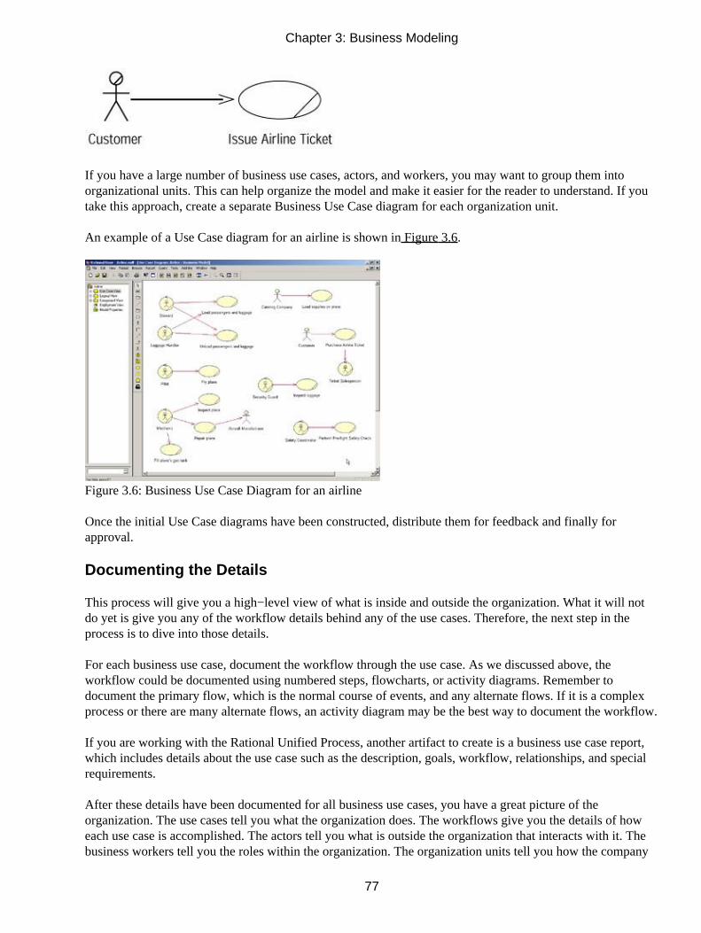
If you have a large number of business use cases, actors, and workers, you may want to group them intoorganizational units. This can help organize the model and make it easier for the reader to understand. If youtake this approach, create a separate Business Use Case diagram for each organization unit.
An example of a Use Case diagram for an airline is shown in Figure 3.6.
Figure 3.6: Business Use Case Diagram for an airline
Once the initial Use Case diagrams have been constructed, distribute them for feedback and finally forapproval.
Documenting the Details
This process will give you a high−level view of what is inside and outside the organization. What it will notdo yet is give you any of the workflow details behind any of the use cases. Therefore, the next step in theprocess is to dive into those details.
For each business use case, document the workflow through the use case. As we discussed above, theworkflow could be documented using numbered steps, flowcharts, or activity diagrams. Remember todocument the primary flow, which is the normal course of events, and any alternate flows. If it is a complexprocess or there are many alternate flows, an activity diagram may be the best way to document the workflow.
If you are working with the Rational Unified Process, another artifact to create is a business use case report,which includes details about the use case such as the description, goals, workflow, relationships, and specialrequirements.
After these details have been documented for all business use cases, you have a great picture of theorganization. The use cases tell you what the organization does. The workflows give you the details of howeach use case is accomplished. The actors tell you what is outside the organization that interacts with it. Thebusiness workers tell you the roles within the organization. The organization units tell you how the company
Chapter 3: Business Modeling
77

is structured. The business use case reports give you additional information about each use case. Finally, theBusiness Use Case diagrams tell you what the relationships are between all of those elements.
Next, let's take a look at how to model these UML concepts in Rational Rose.
Creating Business Use Case Diagrams
Business Use Case diagrams are created in the Use Case view within Rose. After they are created, they willappear in the browser hierarchy under Use Case view. A Business Use Case diagram will show some or all ofthe business actors, business workers, and business use cases in the model and the relationships between them.You can place a specific business actor, worker, or use case on as many Use Case diagrams as you'd like.
Although you can create Business Use Case diagrams directly under the Use Case view, keep in mind thatyour system use cases, system actors, and System Use Case diagrams will also be placed in the Use Caseview. It can be helpful to begin by creating a separate area for the business modeling. This is accomplished byadding a package, which will contain all of your business use cases, business actors, and otherbusiness−modeling elements. Of course, you can create packages within this package to further organize yourbusiness model.
To create a Business Model package (optional):
1. Right−click the Use Case View entry in the browser.
2. Select New → Package.
3. Enter the name of the new package, such as Business Model.
An example of a model that was organized using this method is shown in Figure 3.7. The Business Modelpackage contains all business use cases, business workers, business actors, and Business Activity diagrams,while the System Model package contains all of the technical details for the system itself.
Chapter 3: Business Modeling
78

Figure 3.7: Business Model package
To create a new Business Use Case diagram:
1. Right−click the Business Model package in the Use Case view in the browser. If you did not create abusiness−modeling package within the Use Case view, right−click the Use Case View entry.
2. Select New → Use Case Diagram from the shortcut menu.
3. With the new diagram selected, type in the name of your new diagram.
4. Double−click the name of the new diagram in the browser to open it.
To open an existing Business Use Case diagram:
1. Locate the Business Use Case diagram in the Use Case view in the browser.
2. Double−click the Business Use Case diagram's name to open it.
OR
1. Select Browse → Use Case Diagram.
2. In the Package list box, select the package that contains the diagram you want to open.
3. In the Use Case Diagrams list box, select the diagram you want to open.
4. Press OK.
Deleting Business Use Case Diagrams
If you need to delete a Business Use Case diagram, you can do so in the browser. The business use cases,business actors, and other model elements on the diagram will not be deleted from the model. To delete adiagram, simply right−click it in the browser and select the Delete option from the shortcut menu.
Warning Rose does not allow you to undo a deletion of a diagram or to delete the Use Case diagram calledMain.
Chapter 3: Business Modeling
79

The Use Case Diagram Toolbar
When creating a Business Use Case diagram, the toolbar that will display shows the icons that are typicallyused for a System Use Case diagram. We will need to customize the toolbar to include the business−modelingicons.
To customize the Use Case toolbar:
1. Right−click the Use Case toolbar and select the Customize option. The window displayed in Figure3.8 will appear.
Figure 3.8: Customizing the Use Case toolbar
2. Find the business−modeling toolbar buttons in the Available Toolbar Buttons list box and press theAdd key to add them to the toolbar.
Table 3.1 lists the business−modeling icons that are available to add to the Use Case Diagram toolbar. Notethat there are other icons available on the toolbar. Table 3.1, however, lists only the business−modeling icons.We will discuss the other icons in Chapter 4, "Use Cases and Actors."
Note In Rose, all of the business−modeling icons will be displayed in yellow.Table 3.1: Business−Modeling Icons in the Use Case Diagram Toolbar
Icon Button Purpose
Business Actor Adds a new business actor, who is external to the organization
Business Worker Adds a new business worker, who is internal to the organization
Organization Unit Adds a new organization unit, which is used to group businessworkers and other business−modeling elements
Business Use Case Adds a new business use case
Business Use Case RealizationAdds a new business use case realization
Business Entity Adds a new business entity
Adding Business Use Cases
To add a business use case, first create or open a Use Case diagram and then add the new business use case tothe diagram. When you create the business use case with this method, it is automatically added to the browser.
To add a new business use case:
1.
Chapter 3: Business Modeling
80

Select the Business Use Case button from the toolbar.
2. Click anywhere inside the Use Case diagram. The new use case will be named NewUseCase bydefault.
3. With the new use case selected, type in the name of the new use case.
4. Note that the new use case has been automatically added to the browser under the Use Case view.
To add an existing business use case to a Use Case diagram:
1. Drag the business use case from the browser to the open Use Case diagram and drop it anywhere inthe diagram.
OR
Select Query → Add Use Cases. A dialog box will display, as in Figure 3.9, which will allow you toselect and add existing use cases.
Figure 3.9: Adding existing business use cases to a Use Case diagram
2. In the Package drop−down list box, select the package that contains the business use case(s) you wantto add.
3. Move the business use case(s) you want to add from the Use Cases list box to the Selected Use Caseslist box.
4. Press OK to add the business use cases to the diagram.
Business Use Case Specifications
In Rose, you can specify the name, priority, and other details for each business use case through the use casespecification window, shown in Figure 3.10.
Chapter 3: Business Modeling
81

Figure 3.10: Use case specification window
In the following sections, we'll take a look at each of the specifications available on the tabs of this window.But first, you should know the methods to use for viewing the specifications.
To open the business use case specifications:
1. Right−click the business use case on a Use Case diagram.
2. Select Open Specification from the shortcut menu.
OR
1. Right−click the use case in the browser.
2. Select Open Specification from the shortcut menu.
OR
1. Select the use case on a Use Case diagram.
2. Select Browse → Specification.
Chapter 3: Business Modeling
82

OR
1. Select the use case on a Use Case diagram.
2. Press Ctrl+B.
Assigning a Priority to a Business Use Case
To help you manage the project, you may want to prioritize the business use cases. You could use the priority,for example, to determine in what order the business use cases will be analyzed and documented. The Rosespecifications window provides a field called Rank, which can be used to prioritize the business use cases. Itdoes not set up a numbering scheme for you, but you can use letters, numbers, or any other way of prioritizingthe use cases.
To assign a priority to a business use case:
1. Right−click the business use case in the browser or on the Use Case diagram.
2. Select Open Specification from the shortcut menu.
3. On the General tab, enter the priority in the Rank field.
Viewing Diagrams for a Business Use Case
As you analyze a business use case, you may create a number of activity diagrams to document the workflow.Using the specification window or the browser, you can see a list of all of the diagrams for this particularbusiness use case. Note that this list does not show you on which diagrams the use case resides; instead itshows you which diagrams contain some details for the use case.
To view the diagrams for a business use case:
1. Right−click the business use case in the browser or on a Use Case diagram.
2. Select Open Specification from the shortcut menu.
3. The diagrams will be listed on the Diagrams tab of the specification window, as shown in Figure 3.11.In this example, the use case has five activity diagrams.
Chapter 3: Business Modeling
83

Figure 3.11: Diagrams tab of a use case specification window
OR
Look through the browser. The diagrams for the use case will appear underneath the business use case in thebrowser, as shown in Figure 3.12.
Figure 3.12: Diagrams for a use case
Chapter 3: Business Modeling
84

To open a diagram for a use case:
Double−click the diagram name on the Diagrams tab of the use case specification window.
OR
Right−click the diagram name on the Diagrams tab of the use case specification window and select OpenDiagram from the shortcut menu.
OR
Double−click the diagram in the browser.
To add a diagram to a use case:
1. Right−click anywhere inside the Diagrams tab of the use case specification window.
2. From the shortcut menu, select the type of diagram (Use Case, Sequence, Collaboration, Statechart,Activity, or Class) you want to add.
3. Enter the name of the new diagram.
OR
1. Right−click the use case in the browser.
2. Select New → (Collaboration Diagram, Sequence Diagram, Class Diagram, Use Case Diagram,Statechart Diagram, Activity Diagram) from the shortcut menu.
3. Enter the name of the new diagram.
To delete a diagram for a use case:
1. Right−click the diagram name on the Diagrams tab of the use case specification window.
2. Select Delete from the shortcut menu.
OR
1. Right−click the diagram name in the browser.
2.
Chapter 3: Business Modeling
85

Select Delete from the shortcut menu.
Viewing Relationships for a Business Use Case
A relationship is a link between the business use case and a business actor or worker. It shows which businessactor or worker initiates the business use case. As with diagrams, you can view the relationships for aparticular business use case either through the specifications window or directly in the Rose browser. In thespecifications window, the relationships are listed in the Relations tab, as shown in Figure 3.13.
Figure 3.13: Relations tab of a use case specification window
To view the relationships for a use case:
1. Right−click the use case in the browser or on a Use Case diagram.
2. Select Open Specification from the shortcut menu.
3. The relationships will be listed on the Relations tab. The actor or worker who initiates the use case (orwho is a client of the use case's functionality) will be listed in the Client column. The business usecase itself (which supplies the functionality) is listed in the Supplier column.
OR
1. Select the use case on a Use Case diagram.
2. Select Report → Show Usage.
OR
Simply look at the hierarchy in the browser. The relationships for the business use case will be in the treeviewbelow the use case itself.
Chapter 3: Business Modeling
86

To view the relationship specifications:
1. Double−click the relationship in the list.
2. The relationship specification window will appear. See the section "Working with Relationships" laterin this chapter for a detailed description of relationship specifications.
OR
1. Right−click the relationship in the list.
2. Select Specification from the shortcut menu.
3. The relationship specification window will appear. See the section "Working with Relationships" laterin this chapter for a detailed description of relationship specifications.
To delete a relationship:
1. Right−click the relationship in the list.
2. Select Delete from the shortcut menu.
Working with Business Actors
As you now know, a business actor is anyone or anything outside the business that interacts with it. Once youidentify the business actors for your organization, the next step is to add them to the Rose model and createrelationships between the business actors and business use cases.
Adding Business Actors
Like business use cases, business actors are added to the Rose model by adding them to a Use Case diagram.The first step in the process is to create or open a Use Case diagram. Once you have, you can add businessactors using the toolbar.
To add a business actor to a Use Case diagram:
1.
Chapter 3: Business Modeling
87

Select the Business Actor button from the toolbar (the yellow actor icon is a business actor).
2. Click anywhere inside the Use Case diagram. The new business actor will be named NewClass bydefault.
3. With the new actor selected, type in its name. Note that the new business actor has been automaticallyadded to the browser under the Use Case view.
Adding Actor Specifications
Details about the business actor, such as the name, relationships, and attributes, are controlled through thebusiness actor specifications window, shown in Figure 3.14.
Figure 3.14: Business actor specification window
As you work with classes later in this book, you may note that the actor specification window and the classspecification window are very similar. This is because Rose treats an actor as a specialized form of a class.The actor specification window includes the same fields as the class specification window, but some of thesefields are disabled for actors.
To open the business actor specifications:
1. Right−click the business actor on the Use Case diagram.
2. Select Open Specification from the shortcut menu.
OR
1. Right−click the actor in the browser.
2. Select Open Specification from the shortcut menu.
Chapter 3: Business Modeling
88

OR
1. Select the actor on the Use Case diagram.
2. Select Browse Specification.
OR
1. Select the actor on the Use Case diagram.
2. Press Ctrl+B.
Assigning an Actor Stereotype
A stereotype is a way to categorize model elements in UML. Stereotypes are used when you have manydifferent types of one element. For example, Visual Basic has a number of different types of classes: interface,form, control, collection, and so on. Each of these is represented in UML as a different stereotype.
The same concept applies to business actors. You may have several different types of business actors: thosefrom supplier companies, those from government agencies, those from customer companies, and so on. If youwould like, you can create your own stereotypes to categorize your business actors. You assign a stereotype toa business actor in the specifications window.
To assign a business actor stereotype:
1. Right−click the business actor in the browser or on a Use Case diagram.
2. Select Open Specification from the shortcut menu.
3. In the Stereotype field, enter the business actor stereotype.
Warning If you change the stereotype of a business actor, Rose will no longer display the actor using theUML actor symbol. It will display it as a box instead. This won't affect the rest of your model, butmay make the Use Case diagram harder to understand.
Setting Business Actor Multiplicity
Multiplicity refers to the number of instances you expect to have for a particular business actor. For example,you may expect to have 300,000 people play the role of customer. You can capture this information in thespecifications window.
Rose provides you with several multiplicity options:
Multiplicity Meaning
Chapter 3: Business Modeling
89

0..0 Zero
0..1 Zero or one
0..n Zero or more
1..1 Exactly one
1..n One or more
n (default) ManyOr, you can enter your own multiplicity, using one of the following formats:
Format Meaning Example
<number> Exactly <number> 3
<number 1>..<number 2> Between <number 1> and <number 2> 3..7
<number>..n <number> or more 3..n
<number 1>,<number 2> <number 1> or <number 2> 3, 7
<number 1>,<number 2>.. <number 3> Exactly <number 1> or between <number2> and <number 3>
3, 7–9
<number 1>..<number 2>, <number 3>..<number 4>Between <number 1> and <number 2> orbetween <number 3> and <number 4>
3–5, 7–10
To set business actor multiplicity:
1. Right−click the business actor in the browser or on a Use Case diagram.
2. Select Open Specification from the shortcut menu.
3. Select the Detail tab.
4. Select from the Multiplicity drop−down list box, or type in the business actor's multiplicity using oneof the formats listed above.
Viewing Relationships for a Business Actor
As with business use cases, you can view all of the relationships for a business actor either by using theRelations tab in the specification window or by going through the browser.
To view the relationships for a business actor:
1. Right−click the business actor in the browser or on a Use Case diagram.
2. Select Open Specification from the shortcut menu. The relationships will be listed on the Relationstab.
OR
Chapter 3: Business Modeling
90

Look at the browser window. All of the business actor's relationships will be listed under it in thetreeview.
To view the relationship specifications:
1. Double−click the relationship in the list.
2. The relationship specification window will appear. See the upcoming section "Working withRelationships" for a detailed description of relationship specifications.
OR
1. Right−click the relationship in the list.
2. Select Specification from the shortcut menu.
3. The relationship specification window will appear. See the upcoming section "Working withRelationships" for a detailed description of relationship specifications.
To delete a relationship:
1. Right−click the relationship in the list.
2. Select Delete from the shortcut menu.
Working with Relationships
In business modeling, there are two types of relationships that are used: association relationships andgeneralization relationships. Association relationships are links between business actors and business usecases or between business workers and business use cases. Generalization relationships show an inheritancestructure among business−modeling elements. In this section, we will discuss these two types of relationshipsand how to model them in Rose.
Association Relationship
An association relationship is a relationship between a business actor or business worker and a business usecase. It indicates that a particular business actor or business worker initiates the functionality provided by theuse case. The relationship is shown as an arrow:
Chapter 3: Business Modeling
91

The direction of the arrow indicates who initiates the communication. In the example above, the customerinitiates the Issue Airline Ticket transaction. In the following example, after the pilot initiates the "CancelFlight" business use case, the organization initiates communication with the customer.
We can see from the direction of the arrows that the pilot begins the process and that during the cancellationof the flight, the organization is responsible for notifying the customer.
To add a communicates relationship:
1. Select the Unidirectional Association toolbar button.
2. Drag the mouse from the business actor or business worker to the business use case (or from thebusiness use case to the business actor or worker if the organization initiates the communication).
3. Rose will draw a relationship between the business use case and the business actor or worker.
To delete a communicates relationship:
1. Select the relationship on the Use Case diagram.
2. Select Edit → Delete from Model, or press Ctrl+D.
Generalization Relationship
A generalization relationship is used when there are two or more business actors, business workers, orbusiness use cases that are very similar. As an example, there may be two different groups of people sellingairline tickets: phone representatives and staff who work at the airport counter for in−person sales. For themost part, these two groups of people do the same job, but there are some differences in their responsibilities.
In UML, you can model this situation through a generalization relationship. We create a generic businessworker called ticket salesperson, and then create two more business workers, one for each type of salesperson.You can see this example modeled in Figure 3.15.
Chapter 3: Business Modeling
92

Figure 3.15: Generalization relationship
In a generalization relationship, the arrow points from the specific actor to the generic actor. Someone readingthis diagram would say that there are two types of ticket salespeople: phone salesperson and countersalesperson.
The generic actor may actually be an abstract actor. An abstract actor is one that is never directly instantiated.In this example, no one ever plays the role of a ticket salesperson; they are always either a phone salespersonor a counter salesperson. The ticket salesperson actor is just there to hold the commonality between phone andcounter salespeople. Because no one ever directly plays that role, ticket salesperson is an abstract businessactor. Phone salesperson and counter salesperson, on the other hand, are examples of concrete business actorsbecause people do directly play those roles.
A fairly recent evolution of UML is in generalization relationships between use cases. You can use this typeof relationship when you have two or more use cases that are very similar but that still have some differences.First, you create an abstract use case, much the same as we did for business actors. This abstract use caseholds the elements that are common between the other business use cases. You then inherit the other businessuse cases from the abstract business use case with a generalization relationship.
To add a generalization relationship:
1. Add the business actors, business workers, or business use cases to the Use Case diagram.
2. Select the Generalization button from the toolbar.
3. Drag from the concrete business actor, worker, or use case to the abstract business actor, worker, oruse case.
4. Open the specification window for the abstract business actor, worker, or use case.
5. Select the Detail tab.
6. Check the Abstract check box.
To delete a generalization relationship:
1.
Chapter 3: Business Modeling
93

Select the relationship on the Use Case diagram.
2. Select Edit → Delete from Model, or press Ctrl+D.
Warning Be careful of using too many generalization relationships. Unless the reader is familiar withgeneralizations, they may make the diagram very difficult to understand.
Working with Organization Units
As we discussed above, an organization unit is a UML construct used to group business actors, businessworkers, and business use cases together. Typically, a UML organization unit corresponds to a division orgroup within the organization. We might have organization units called Sales, Finance, Manufacturing, andHuman Resources for those divisions within the company. Each organization unit would hold the businessactors, workers, and use cases appropriate for that division. It can also be helpful to create a Use Case diagramspecific to that organization unit, which shows only the business actors, workers, and use cases for that unit.
As you know from earlier in this chapter, an organization unit is represented by the following symbol:
Adding Organization Units
In Rose, you can add organization units through a Use Case diagram. Once the units have been created, youcan create new business actors, workers, or use cases inside them, or move existing business actors, workers,or use cases into the new unit. You can create as many organization units as you need, and create organizationunits within organization units to further organize the business model.
To add an organization unit:
1. Open a Use Case diagram.
2. Use the Organization Unit toolbar button to add a new unit. It will be named NewPackage by default,and will be automatically added to the browser.
3. Type in the name of the new organization unit.
To move an item into an organization unit, go to the browser and drag and drop the item from its existinglocation to the new organization unit.
Chapter 3: Business Modeling
94

Deleting Organization Units
Organization units can be deleted from the model using either the browser or a Use Case diagram. When youdelete an organization unit, all business actors, business workers, business use cases, activity diagrams, and allother model elements within it will also be deleted from the model.
To remove an organization unit from a diagram without deleting it from the model:
1. Select the organization unit on a Use Case diagram.
2. Press the Delete key.
3. Note that the unit has been removed from the Use Case diagram, but it still exists in the browser andon other Use Case diagrams.
To delete an organization unit from the model:
1. Right−click the unit in the browser.
2. Select Delete from the shortcut menu.
OR
1. Select the organization on a Use Case diagram.
2. Select Edit → Delete from Model, or press Ctrl+D.
Warning When you delete an organization unit from the model, all business use cases, business actors, andother items in the unit will also be deleted from the model.
Activity Diagrams
In Rose, you can use an activity diagram to model the workflow through a particular business use case. Themain elements on an activity diagram are:
• Swimlanes, which show who is responsible for performing the tasks on the diagram.
• Activities, which are steps in the workflow.
• Actions, which are steps within an activity. Actions may occur when entering the activity, exiting theactivity, while inside the activity, or upon a specific event.
•
Chapter 3: Business Modeling
95

Business objects, which are entities affected by the workflow.
• Transitions, which show how the workflow moves from one activity to another.
• Decision points, which show where a decision needs to be made during the workflow.
• Synchronizations, which show when two or more steps in the workflow occur simultaneously.
• The start state, which shows where the workflow begins.
• The end state, which shows where the workflow ends.
In this section, we'll take a look at how to model these different parts of the activity diagram using Rose.
Adding an Activity Diagram
You can create as many activity diagrams as you need for a particular business use case. The activitydiagrams for a business use case will appear in the State/Activity Model area under the business use case inthe browser.
To add an activity diagram:
1. Right−click the business use case in the browser.
2. Select New → Activity Diagram from the menu.
3. Rose will create an entry in the browser called State/Activity Model under the business use case, asshown in Figure 3.16. The new activity diagram will appear under the State/Activity Model entry.
Figure 3.16: Adding an activity diagram
4.
Chapter 3: Business Modeling
96

Name the new activity diagram.
5. Double−click the diagram to open it.
Adding Details to an Activity Diagram
Once the diagram has been created, the next step is to add the swimlanes, activities, and other details to it.This is accomplished using the Activity Diagram toolbar. Table 3.2 lists the icons available on the ActivityDiagram toolbar and the purpose of each.
Table 3.2: Icons on the Activity Diagram Toolbar
Icon Button Purpose
Selection Tool Returns the cursor to an arrow to select a toolbar button
Text Box Adds a text box to the diagram
Note Adds a note to the diagram
Anchor Note to Item Connects a note to an item in the diagram
State Adds a state to the diagram
Activity Adds an activity to the diagram
Start State Adds a start state to the diagram
End State Adds an end state to the diagram
State Transition Transitions from one activity or state to another
Transition to Self Transitions to the current activity or state
Horizontal Synchronization Shows where two or more activities occur simultaneously
Vertical Synchronization Shows where two or more activities occur simultaneously
Decision Shows decision points in the workflow
Swimlane Shows who is responsible for completing activities
Object Shows an object that is affected by the workflow
Object Flow Shows what activities change the state of the object
To add a swimlane to the diagram:
1. Select the Swimlane toolbar button.
2. Click inside the diagram. A new swimlane will appear, and will be titled NewSwimlane by default, asshown in Figure 3.17.
Chapter 3: Business Modeling
97

Figure 3.17: Swimlane in an activity diagram
3. Name the new swimlane, using the name of a business worker or organization unit.
To add a start state to the diagram:
1. Select the Start State toolbar button.
2. Click inside the diagram within the swimlane for the worker or unit who will start the workflow.
To add activities to the diagram:
1. Select the Activity toolbar button.
2. Click inside the diagram within the swimlane for the worker or unit who is responsible for performingthe activity.
3. Name the new activity.
To add actions to the activities:
1. Right−click the activity.
2. Select the Open Specification option. The activity specification window will appear.
3.
Chapter 3: Business Modeling
98

Select the Actions tab.
4. Right−click inside the tab and select Insert. The default action type, called Entry, will appear in theType column, as shown in Figure 3.18.
Figure 3.18: Adding actions to an activity
5. Double−click the new action. The action specification window will appear.
6. In the When drop−down list box, select the appropriate option:
♦ On Entry for actions that occur when entering the activity
♦ On Exit for actions that occur when leaving the activity
♦ Do for actions that occur within the activity
♦ On Event for actions that occur when a specific event happens
7. Enter the action's name, as shown in Figure 3.19.
Chapter 3: Business Modeling
99

Figure 3.19: Action specification window
8. If the action was on an event, enter the event that triggers the action, any arguments to the event, andany guard conditions. A guard condition must be true for the action to occur.
9. Click OK to close the action specification.
10. Click OK to close the activity specification.
To add a business object:
1. Select the Object toolbar button.
Note The Object button does not appear by default when you install Rose. You may need tocustomize the toolbar to see it.
2. Click inside the diagram within the swimlane for the worker or unit responsible for performing theactivity that will affect the object.
3. Name the new object.
To draw transitions between activities:
1.
Chapter 3: Business Modeling
100

Select the State Transition toolbar button.
2. Drag and drop from one activity to another.
To set a condition on the transition:
1. Right−click the transition.
2. Select the Open Specification option.
3. Select the Detail tab.
4. Type the condition in the Guard Condition field. When the condition is displayed on the diagram, itwill be surrounded by square brackets to indicate that it is a guard condition, as shown in Figure 3.20.You can also type the guard condition directly on the transition by enclosing it in square brackets.
Figure 3.20: Guard conditions on transitions
To add a decision point:
1. Select the Decision toolbar button.
2. Click inside the diagram to place the decision.
3. Draw two or more transitions from the decision, one for each decision possibility.
To add a synchronization:
1. Select the Horizontal or Vertical Synchronization toolbar button.
2. Click inside the diagram to place the synchronization.
3. Draw two or more transitions from the synchronization, one to each activity that will occursimultaneously, as shown in Figure 3.21.
Chapter 3: Business Modeling
101

Figure 3.21: Synchronization in an activity diagram
To show which activities affect a business object:
1. Select the Object Flow toolbar button.
2. Drag and drop from the activity that changes the state of the object to the object itself. A dashed arrowwill appear between the two. Figure 3.22 shows an example of how creating a rejection letter sets thestate of the request object to Denied.
Figure 3.22: Object flow in an activity diagram
Summary
In this chapter we discussed business modeling. We began by examining why we would want to do businessmodeling in the first place. It is not right for all projects, but there are many times when business modelingcan add a great deal of value to a project. We then moved on to discuss some of the fundamental elements ofbusiness modeling, including business actors, business use cases, business workers, and organization units,and how you would find some of these things in your organization.
From there, we moved into a discussion of the details of a business use case. You model the flow through ause case either by using text or via an activity diagram. Activity diagrams have the advantage of clarity andease of use, especially when considering a workflow that is large and complex. We examined the differentpieces of an activity diagram, including swimlanes, activities, actions, objects, transitions, andsynchronizations.
Once we examined the business−modeling ideas, we moved on to how these items can be modeled usingRational Rose. We walked through the Rose toolbars and specification windows to examine the details of the
Chapter 3: Business Modeling
102

elements that can be added to a Rose model.
In the next chapter, we'll begin the process of system modeling. Business modeling isn't as concerned withwhat is automated by a particular system. System modeling, in contrast, is focused on the implementation of aparticular software project. Business modeling helps us set the context for the system model.
Chapter 3: Business Modeling
103

Chapter 4: Use Cases and ActorsUse cases and actors define the scope of the system you are building. Use cases include anything that is withinthe system; actors include anything that is external to the system. We'll start this chapter by discussing someof the fundamental concepts of use case, or system, modeling: use case, actor, association relationship,includes relationship, extends relationship, generalization relationship, flow of events, activity diagram, andUse Case diagram. Then, we'll look at how to model each of these in Rose.
At the end of the chapter, we provide an exercise that builds on the business case of Chapter 3, "BusinessModeling," by adding use cases, actors, and Use Case diagrams to a Rose model.
• Using the Use Case view and Use Case diagrams
• Working with use cases, actors, and relationships
• Using notes
• Adding and deleting Use Case packages
Use Case Modeling Concepts
In this section, we'll discuss some of the fundamental concepts of use case modeling: use cases, actors,relationships, activity diagrams, and Use Case diagrams. If you have gone through the business modelingprocess, you will notice the similarities between what we will discuss here and business modeling. Businessmodeling also works with actors, use cases, relationships, activity diagrams, and Use Case diagrams. Thedifference is that business modeling focuses on the organization, while system modeling focuses on thesystem being built. The terms system use case or system actor are sometimes used to differentiate them frombusiness use cases or business actors.
Item Business Modeling System Modeling
Use case Describes what the business doesDescribes what a system within thebusiness does
Actor External to the organization External to the system (may beinternal to the organization)
Business worker Internal to the organization Not usedIn the last chapter, we went through the business modeling process for an airline. During that example, wefocused on the business of being an airline, not on what systems we would build. Now, we focus in on aparticular system. Assume that we are building a ticket reservation system for the airline. It will eventually letpeople call in or go online to order plane tickets and to change or cancel a reservation.
Actors
An actor is anyone or anything that interacts with the system being built. As we will see shortly, use casesdescribe anything that is inside the system's scope. Actors are anything that is outside the system's scope. In
104

UML, actors are represented with stick figures:
There are three primary types of actors: users of the system, other systems that will interact with the systembeing built, and time.
The first type of actor is a physical person, or a user. These are the most common actors, and are present injust about every system. For our flight reservation system, actors are the people who will be directly using thesystem. Because we know some of the functionality will be available over the Internet, customers can directlyuse the system. We also know that customers can call in to a customer service representative to make areservation. The customer service representative will directly use the system, so this role is an actor as well.
When naming actors, remember to use role names rather than position names. A given individual will playmany roles. John Doe may be a customer service representative, but if he goes online to buy a ticket forhimself, he is playing the role of a customer. Using role names rather than position names will give you amore stable picture of your actors. Position names change over time, as roles and responsibilities are movedfrom one position to another. By using roles, you won't need to update your model every time a new positionis added or a position changes.
The second type of actor is another system. For example, the airline's reservation system may need tointerface with an external application to validate credit cards for purchases. In this example, the external creditapplication is an actor. It is another system that we won't be changing at all, so it is outside the scope of thecurrent project, but it does need to interface with our new system. Any systems like this, which lie just beyondthe boundaries of our application, are actors.
The third type of actor that is commonly used is time. Time becomes an actor when the passing of a certainamount of time triggers some event in the system. For example, part of our airline's promotions may be thechance to win a free ticket. Every day at 3:00 p.m. the system may automatically select a random customer togive a free ticket to. Because time is outside of our control, it is an actor.
Use Cases
A use case is a high−level piece of functionality that the system will provide. In other words, a use caseillustrates how someone might use the system. Let's begin by looking at an example.
Along with our actors, we need to define the use cases for the airline reservation system. It really doesn'tmatter if you identify the use cases or the actors first. In fact, these two steps are usually done together. Toidentify the use cases, we answer the question: What will the system do that provides value to the outsideworld? We can see from our brief vision statement above that it will let users purchase tickets, change areservation, or cancel a reservation. These are all good candidates for use cases; each is some piece offunctionality the system will provide that is of value to the end user. Notice that we didn't include a use case,such as "Get Flight Information" from the legacy system. This is a behind−the−scenes piece of logic that theend user really doesn't care about, so it doesn't qualify as a use case. "Purchase Ticket," "ChangeReservation," or "Cancel Reservation," on the other hand, are things that the end user would care about andhigh−level pieces of functionality the system will provide, so they are good use cases. In UML, a use case is
Chapter 4: Use Cases and Actors
105

represented by the following symbol:
The advantage of looking at a system with use cases is the ability to dissociate the implementation of thesystem from the reason the system is there in the first place. It helps you focus on what is trulyimportant—meeting the customer's needs and expectations without being instantly overwhelmed byimplementation details. By looking at the use cases, the customer can see what functionality will be provided,and can agree to the system scope before the project goes any further.
Use cases take a different approach than traditional methods. Splitting the project into use cases is aprocess−oriented, not an implementation−oriented, way of looking at the system. It is therefore different fromthe functional decomposition approach that is so often taken. While functional decomposition focuses on howto break the problem down further and further into pieces that the system will handle, the use case approachfocuses first on what the user expects from the system.
When you are beginning a project, a natural question is: How do I go about finding the use cases? A good wayto begin is to examine any documentation the customers have provided. For example, a high−level scope orvision document can frequently help you identify the use cases. Consider also each of the stakeholders of theproject. Ask yourself what functionality each stakeholder expects from the system. For each stakeholder, askquestions such as:
• What will the stakeholder need to do with the system?
• Will the stakeholder need to maintain any information (create, read, update, delete)?
• Does the stakeholder need to inform the system about any external events?
• Does the system need to notify the stakeholder about certain changes or events?
As we mentioned before, use cases are an implementation−independent, high−level view of what the userexpects from the system. Let's examine each piece of this definition separately.
First, the use cases are implementation−independent. As you are defining the use cases, assume you arebuilding a manual system. Your use cases should be able to be built in Java, C++, Visual Basic, or on paper.Use cases focus on what the system should do, not how the system will do it. We'll get into the how later on inthe process.
Secondly, the use cases are a high−level view of the system. Your collection of use cases should let thecustomers easily see, at a very high level, your entire system. There should not be so many use cases that thecustomer is forced to wade through pages and pages of documentation just to see what the system will do. Atthe same time, there should be enough use cases to completely describe what the system will do. A typicalsystem will have somewhere between 20 and 70 use cases. (If your system has 3000 use cases, you've lost thebenefit of simplicity.) You can use different types of relationships, called includes and extends relationships,
Chapter 4: Use Cases and Actors
106

to break down the use cases a little if you need to. You can also package the use cases together to form groupsof use cases to help you organize them better. We'll explore these topics later in this chapter.
Finally, the use cases should be focused on what the user will get out of the system. Each use case shouldrepresent a complete transaction between the user and the system that results in something of value to theuser. The use cases should be named in user terms, not technical terms, and should be meaningful to thecustomer. We wouldn't have a use case, for example, called "Interface with the Bank's Credit System toValidate the Credit Card Number." The customer is trying to purchase a ticket, so that's what we call the usecase: "Purchase Ticket." Use cases are typically named with verbs or short verb phrases in the format "<verb><noun>," and describe what the customer sees as the end result. The customer doesn't care how many othersystems you have to interface with, what specific steps need to be taken, or how many lines of code you needto confirm a Visa card. That customer cares only that a ticket was purchased. Again, you focus on the resultthe user expects from the system, not the steps that were taken to achieve the result.
So, when you have the final list of use cases, how do you know if you've found them all? Some questions toask are:
• Is each functional requirement in at least one use case? If a requirement is not in a use case, it will notbe implemented.
• Have you considered how each stakeholder will be using the system?
• What information will each stakeholder be providing for the system?
• What information will each stakeholder be receiving from the system?
• Have you considered maintenance issues? Someone will need to start the system and shut it down.
• Have you identified all of the external systems with which the system will need to interact?
• What information will each external system be providing to the system and receiving from thesystem?
Traceability
As with business modeling, a very important concept to consider at this point is traceability. Each of thesystem use cases should be able to be traced back to a business use case. The system use case is whatimplements part of the functionality in the business use case.
This is not a one−to−one mapping. Business use cases tend to be very high level, so many system use casesmay be needed to support a single business use case. For example, an airline has a business use case called"Repair Plane." If we build a system to support this use case, it will have a lot of system use cases in it, suchas "Enter Problem," "Check Inventory for Available Parts," "Receive Part from Inventory," "Order Part,""Schedule Maintenance," and so on. Each of these system use cases would be traced to the business use case
Chapter 4: Use Cases and Actors
107

called "Repair Plane."
Every system use case must be traced back to a business use case, but not all business use cases will besupported by system use cases. Hypothetically, if the business use case called "Unload Passengers andLuggage" is a completely manual process, then it would not have any supporting system use cases at all. Hereis an example of how system use cases might map to business use cases:
Business Use Case System Use Cases
Repair Plane Enter Problem; Check Inventory for Parts; Receive Part fromInventory; Order Part; Schedule Maintenance
Load Supplies on Plane Determine Needed Supplies; Check Supply Availability; ReserveSupplies; Receive Supplies
Perform Preflight Safety Check Confirm Luggage Inspection; Confirm Passenger Check−In; InspectPlane Exterior; Check Status of Emergency Equipment
If you are using a requirements management tool, such as Rational's Requisite Pro, you can map the systemuse cases to business use cases directly in the tool. If not, it is important to set up a process, even in a simplespreadsheet or database, to ensure that the system use cases are mapped to business use cases. The realpurpose of traceability is ensuring that, at the end of the day when the system is built and implemented, all ofthe requirements are met and all of the code can be traced back to a requirement.
After the system use cases are traced to business use cases, the next step is to trace the requirements to thesystem use cases. Each functional requirement must be traced to a system use case, because the system usecases describe the functionality that will be provided by the system. The system design is driven by the usecases, so if a requirement is not traced to a use case, it will not be considered in the design and may not end upin the final system.
Note Notice that we said functional requirements. There are non−functional requirements, such as systemresponse time or the number of concurrent users supported that do not need to be traced to system usecases. These are typically maintained in a Supplementary Specification document.
Again, if you are using a tool such as Requisite Pro, you can trace the requirements to use cases in the tool. Ifnot, set up a method to ensure that each requirement is traced to a use case. As we go through the wholeprocess, traceability should be shown as in Figure 4.1.
Figure 4.1: Traceability through the life cycle
Flow of Events
The use cases begin to describe what your system will do. To actually build the system, though, you'll needmore specific details. These details are written as the flow of events. The purpose of the flow of events is todocument the flow of logic through the use case. This document will describe in detail what the user of thesystem will do and what the system itself will do.
Although it is detailed, the flow of events is still implementation−independent. You can assume as you arewriting the flow that there will be an automated system. However, you shouldn't yet be concerned withwhether the system will be built in C++, PowerBuilder, or Java. The goal here is describing what the systemwill do, not how the system will do it. The flow of events typically includes:
•
Chapter 4: Use Cases and Actors
108

A brief description
• Preconditions
• Primary flow of events
• Alternate flow of events
• Postconditions
Let's look at these items one at a time.
Description
Each use case should include a short description that explains what the use case will do. The Purchase Ticketuse case from our airline example might have a description like the following: The Purchase Ticket use casewill allow a customer to view available flight information, check availability, and purchase a ticket with acredit card.
The description should be short and to the point, but should include the different types of users who will beexecuting the use case and the end result the user expects to achieve through the use case. As the projectprogresses (especially with a very long project), these use case definitions will help the whole team rememberwhy each use case is included in the project and what the use case is intended to do. They also help reduceconfusion among the team members by documenting a clear purpose for the use case.
Preconditions
The preconditions for a use case list any conditions that have to be met before the use case can start at all. Forexample, a precondition might be that another use case has been executed or that the user has the necessaryaccess rights to run the current use case. Not all use cases will have preconditions.
Use Case diagrams aren't intended to show in which order the use cases are executed. Preconditions, however,can be used to document some of this type of information. For example, the precondition for one use case maybe that another use case has run.
Primary and Alternate Flow of Events
The specific details of the use case are described in the primary and alternate flow of events. The flow ofevents describes, step−by−step, what will happen to execute the functionality in the use case. The flow ofevents focuses on what the system will do, not how it will do it, and is written from the user's perspective. Theprimary and alternate flow of events include:
• How the use case starts
• The various paths through the use case
•
Chapter 4: Use Cases and Actors
109

The normal, or primary, flow through the use case
• Any deviations from the primary flow, known as alternate flows, through the use case
• Any error flows
• How the use case ends
Along with the flow of events in text form, activity diagrams are frequently used. In this section, we'll talkabout the option of using text. We'll go over activity diagrams later in this chapter.
There are three types of flows: the primary, alternate, and error flows. The primary flow is the "happy day"scenario, or the most frequently used path through the use case. When purchasing a ticket, the primary flow isa successful ticket purchase. Alternate flows are deviations from the primary flow that do not suggest an errorcondition. For example, a customer may purchase a ticket using frequent−flyer miles, the customer's creditcard may not be valid, or the requested flight may not be available. Each of these is a legitimate scenario thatthe system will be expected to handle, but doesn't suggest that something has gone wrong with the systemitself. Finally, error flows are deviations from the primary or alternate flows that suggest some sort of errorcondition. For example, the system may be unable to verify the credit card or the flight availability. Errorflows suggest that there is a problem with the system itself.
Using our "Purchase Ticket" use case example, the flow of events might look like the steps in the followingsections.
Primary Flow
The steps for the primary flow of events include:
1. The use case begins when the customer selects the option to view flight information.
2. The system prompts for the departure and destination cities and the departure and return dates.
3. The user enters the departure and destination city, departure date, and return date.
4. The system displays a list of available flights, including the fare.
A1: There are no available flights.
5. The user selects the flight they would like to reserve.
6. The system displays all available fare options for that flight.
7.
Chapter 4: Use Cases and Actors
110

The user selects the fare option they would like to reserve.
A2: The user selects a free ticket through frequent−flyer membership.
8. The system displays the fare that the user will pay.
9. The user confirms the rate.
10. The system prompts for a credit card type, number, name, and expiration date.
11. The user enters the card type, number, name, and expiration date.
12. The system submits the credit purchase.
A6: Account not found
A7: Insufficient funds
E1: Credit system not accessible
13. The system reserves a seat on the plane for the user.
14. The system generates and displays a confirmation code to the user.
15. The user confirms receipt of the code.
16. The use case ends.
Alternate Flows
A1: No available flights
1. The system displays a message that there are no available flights for the departure and destinationcities, departure date, and return date entered.
2. The user confirms the message.
3. The flow returns to the primary flow, step 2.
Chapter 4: Use Cases and Actors
111

A2: Free ticket through frequent−flyer membership
1. The system prompts for the frequent−flyer number.
2. The user enters the number.
3. The system confirms the validity of the number.
A3: Invalid number
4. The system confirms that there are enough miles on this membership to qualify for the free ticket.
A4: Not enough miles to qualify for a free ticket
A5: No frequent−flyer tickets available
5. The ticket fare is set to $0.
6. The flow returns to the primary flow, step 8.
A3: Invalid frequent−flyer number
1. The system displays a message that the frequent−flyer number is invalid.
2. The user reenters the number or selects the option to cancel the frequent−flyer request.
3. If the user reenters the number, the flow returns to step 1 of alternate flow A2.
4. If the user cancels the frequent−flyer request, the flow returns to step 6 of the primary flow.
A4: Not enough frequent−flyer miles to qualify for free ticket
1. The system displays a message that there are not enough miles to qualify. The message contains therequired number of miles and the number of miles available.
2. The flow returns to step 6 of the primary flow.
A5: No frequent−flyer tickets available
1.
Chapter 4: Use Cases and Actors
112

The system displays a message that there are no frequent−flyer tickets available for the selected flight.
2. The flow returns to step 6 of the primary flow.
A6: Credit account not found
3. The system displays a message that the credit account was not found.
4. The flow returns to step 10 of the primary flow.
A7: Insufficient funds
1. The system displays a message that there were not enough funds on the card to complete thetransaction.
2. The flow returns to step 10 of the primary flow.
Error Flows
E1: Credit system not available
1. The system displays a message that the credit system is not available.
2. The flow returns to step 10 of the primary flow.
Notice the pattern in the flow of events: the user does something, then the system does something in response,then the user does something, then the system responds, and so on. Keeping to this pattern as much aspossible helps you ensure that you have a complete understanding of how the conversation between the userand the system should flow. When documenting the flow of events, you can use numbered lists as we havedone here, text in paragraph form, bulleted lists, or even flowcharts. With the user/system pattern, anotherway to document the flow is by using a table:
User Action System Response
Select option to view flight information Prompt for departure and destination cities, departureand arrival dates
Enter departure and destination cities, departire andarrival dates
Display flight number, departure time, and arrivaltime for available flights
… …
… …
… …
… …
Chapter 4: Use Cases and Actors
113

How Detailed Does This Need to Be?
The classic question when documenting a flow of events is how detailed should it be? To answer thatquestion, keep in mind the reviewers of the document. There are three primary users of the flow of events:
1. The customers will be reviewing this document to make sure it accurately reflects their expectations.The flow of events must be detailed enough so that both you and the customer have the sameunderstanding of the system. The more gaps you leave in the details, the greater the potential fordisconnects in expectations. At the same time, you don't want to get into implementation details thatthe customers won't understand or won't care about. A short answer for most customers is: get asdetailed as you can without getting into the implementation. Try to avoid phrases such as "The systemwill take frequent flyers into account." What does "into account" mean? You want to be sure that bothyou and the customer understand what that phrase means in that situation.
2. The system designers will be using it to create the system design and eventually to build the system.The flow of events must give them enough information to understand the sequence of events thatneeds to occur through the use case. Although the flow of events isn't implementation−specific (try toavoid words like "menu," "window," "treeview," or other phrases that will tie the developers to aparticular implementation), it does have a lot of information about how the system is supposed tobehave. Be sure there is no ambiguity about what the users want, so that the designers will understandthe users' needs.
3. The quality assurance team will use the flow of events to create test scripts. Because the flow ofevents lists step−by−step what the system should do, the testing team can use it as a basis forcomparison against what the system does do when all is said and done. The flow of events won't be atest script by itself, but it can serve as great input into a test case.
As you are writing the flow, focus on what and be sure to avoid detailed discussions of how. Think of writinga recipe. In a recipe, you would say "Add two eggs." You wouldn't say "Go to the refrigerator. Get two eggsfrom the door. Pick up the first egg. Crack the egg against the side of the bowl…." In a flow of events, youmight say "Validate the user ID," but you wouldn't specify that this is done by looking at a particular table in adatabase. Focus on the information that is exchanged between the user and the system, not on the details ofhow the system will be implemented.
Postconditions
Postconditions are conditions that must always be true after the use case has finished executing. Likepreconditions, postconditions can be used to add information about the order in which the use cases are run.If, for example, one use case must always be run after another use case, you can document this in thepostconditions. Not every use case will have postconditions.
Relationships
So far, we have taken a look at use cases and actors individually. Now we'll explore the relationships betweenuse cases and actors to get a full picture of our system.
The association relationship is used to show the relationship between a use case and an actor.
Chapter 4: Use Cases and Actors
114

There are three types of relationships between use cases: an includes relationship, an extends relationship, anda generalization relationship. These relationships are used when there is a certain amount of commonalitybetween the use cases.
There is only one relationship allowed between actors. This is a generalization relationship.
Association Relationship
The relationship between an actor and a use case is an association relationship. In UML, associationrelationships are diagrammed using an arrow:
In this example, the use case initiates communication with the credit system actor. As the "Purchase Ticket"use case is being run, the reservation system initiates communication with the credit system to check the cardand complete the transaction. Although information flows in both directions—from the reservation system tothe credit system and back again—the arrow indicates only who initiated the communication.
With the exception of use cases in includes and extends relationships, every use case must be initiated by anactor.
Includes Relationship
An includes relationship allows one use case to use the functionality provided by another use case. Thisrelationship can be used in one of two cases.
First, if two or more use cases have a large piece of functionality that is identical, this functionality can besplit into its own use case. Each of the other use cases can then have an includes relationship with this new usecase.
The second case where an includes relationship is helpful is a situation in which a single use case has anunusually large amount of functionality. An includes relationship can be used to model two smaller use casesinstead.
Includes relationships are shown in Rose with dashed arrows and the word <<include>>, as in Figure 4.2.
Figure 4.2: An includes relationship
Chapter 4: Use Cases and Actors
115

In this example, the "Check Credit" use case will check that a valid card number was entered and that thecredit account has sufficient funds to complete the transaction. Because this functionality is used during thePurchase Ticket process, there is an includes relationship between them.
An includes relationship suggests that one use case always uses the functionality provided by another. Nomatter how you proceed through the Purchase Ticket use case, the "Check Credit" use case is always run.
Extends Relationship
In contrast, an extends relationship allows one use case the option to extend the functionality provided byanother use case. It is very similar to an includes relationship, because in both of these types of relationships,you separate some common functionality into its own use case.
In UML, the extends relationship is shown as a dashed arrow with the word <<extend>>, as in Figure 4.3.
Figure 4.3: An extends relationship
In this example, the "Check Credit" use case extends the "Change Reservation" use case. While the "ChangeReservation" use case is running, "Check Credit" runs if and only if the amount of the reservation haschanged. If the amount has not changed, "Check Credit" does not need to run.
Because "Check Credit" is optionally run, there is an extends relationship between the use cases. The arrow isdrawn from the use case that is optionally run ("Check Credit") to the use case that is being extended("Change Reservation").
Generalization Relationship
A generalization relationship is used to show that several actors or use cases have some commonality. Forexample, you may have two types of customers: corporate customers and individual customers. You canmodel this relationship using the notation displayed in Figure 4.4.
Chapter 4: Use Cases and Actors
116

Figure 4.4: Actor generalization relationship
This diagram shows our two types of customers: individual and corporate. Because the individual andcorporate actors will be directly instantiated, they are called concrete actors. Because the customer actor isnever directly instantiated, it is an abstract actor. It exists only to show that there are two types of customers.
We can break down things even further if we need to. Say there are two types of corporate customers:government agencies and private companies. We can modify the diagram to look like Figure 4.5.
Figure 4.5: Modified actor generalization relationship
It isn't always necessary to create these types of relationships. In general, they are needed only if one type ofactor behaves differently than another type, as far as the system is concerned. If the corporate customers willbe initiating some use cases that individual customers will not, it's probably worth including the actorgeneralizations. If both types of customers use the same use cases, it's probably not necessary to show an actorgeneralization. If both types use the same use cases, but slightly differently, it still isn't worth including thegeneralization. The slight differences are documented in the flow of events for the use cases.
Chapter 4: Use Cases and Actors
117

Tip The point of these diagrams is communication. If including an actor generalization would give the teamsome useful information, then include it. Otherwise, don't clutter up the diagrams with them.
The same concept is true for use cases. If you have a base set of functionality that one or more use casesexpand upon, you can create a generic use case and then inherit the other use cases from it with ageneralization relationship.
Use Case Diagrams
A Use Case diagram shows you some of the use cases in your system, some of the actors in your system, andthe relationships between them. As you know, a use case is a high−level piece of functionality that the systemwill provide. An actor is anyone or anything that interacts with the system being built. An example of a UseCase diagram is shown in Figure 4.6.
Figure 4.6: Sample Use Case diagram
In this diagram, we see the system actors, the system use cases, and the relationships between them. Becausethe system will be available both online and over the phone, the customer and customer service representativecan initiate the same use cases. We have one extends relationship and one includes relationship. There areeight major pieces of functionality the system will provide: purchasing tickets, changing a reservation,checking credit, canceling a reservation, viewing a customer itinerary, reserving a hotel room, reserving arental car, and setting up the flight schedule.
One of the major benefits of Use Case diagrams is communication. Your customers can look at this diagramand receive a great deal of information. By looking at the use cases, they will know what functionality will beincluded in the system. By looking at the actors, they will know exactly who will be interfacing with thesystem. By looking at the set of use cases and actors, they will know exactly what the scope of the project willbe. This can help them identify up front any missing functionality. For example, someone could look at thediagram above and say, "That's great, but I also need the ability to check my frequent−flyer membership tosee how many miles I have." If so, all we need to do is add another use case called "View Frequent−FlyerInformation."
Frequently, you will want to create several Use Case diagrams for a single system. A high−level diagram,usually called Main in Rational Rose, will show you just the packages, or groupings, of use cases. Other
Chapter 4: Use Cases and Actors
118

diagrams will show you sets of use cases and actors. You may also want to create a single diagram with all ofthe use cases and all of the actors. How many Use Case diagrams you create and what you name them isentirely up to you. Be sure that the diagrams have enough information to be useful, but are not so crowded asto be confusing.
Tip Rational Rose can automatically create diagrams with all modeling elements in a package. In the rose.ini,set the AutoConstructMainDiagrams=Yes flag to enable this feature and a main diagram will beautomatically created for each package with all modeling elements of the package.
Use Case diagrams fulfill a specific purpose: to document the actors (everything outside the system scope),the use cases (everything inside the system scope), and their relationships. Some things to keep in mind as youare creating Use Case diagrams include:
• Do not model actor−to−actor associations (although generalizations are OK). By definition, the actorsare outside the scope of the current project. The communication between the actors, therefore, is alsooutside the scope of what you're building. You can use a workflow diagram to examine the actorassociations.
• Do not draw an association directly between two use cases (although includes or extends relationshipsare OK). The diagrams show what use cases are available, but don't show in which order the use caseswill be executed, so there shouldn't be an association between use cases.
• Every use case must be initiated by an actor. That is, there should be an arrow starting with an actorand ending with the use case. Again, the exception here is an includes or extends relationship.
• Think of the database as a layer underneath the entire Use Case diagram. You can enter information inthe database using one use case, and then access that information from the database in another usecase. You don't have to draw associations from one use case to another to show information flow.
Activity Diagrams
An activity diagram is another way to model the flow of events. Using text, as we did in the example above, isuseful, but it can be difficult to read and understand if the logic is complex, if there are a lot of alternate flows,or if your customers simply prefer diagrams over text.
An activity diagram shows you the same information as a textual flow of events would. We use activitydiagrams in business modeling to depict the workflow through a business process. Here, we will use them todepict the flow through a piece of the system.
Figure 4.7 is the activity diagram that corresponds to the flow of events for purchasing an airline ticket fromearlier in this chapter.
Chapter 4: Use Cases and Actors
119

Figure 4.7: Activity diagram
As you can see, the activity diagram can be an easier way to communicate the steps in the flow. Let's look atthe different pieces of notation in this diagram.
Activity
As the name implies, an activity is one of the essential pieces of an activity diagram. An activity is simply astep in the process. The steps we outlined in the text above become our activities here. An activity is modeledusing the following symbol:
We can add more detailed steps to the activity by using actions. Actions are smaller steps that take placewithin an activity. They may occur at one of four times:
• Upon entering the activity. An entry action occurs as soon as the activity begins, and is marked withthe word "entry."
• When exiting the activity. An exit action occurs as you are leaving the activity, and is marked with theword "exit."
• While performing the activity. These actions occur while in the activity and continue until you leavethe activity. They are marked with the word "do."
•
Chapter 4: Use Cases and Actors
120

Upon a specific event. These actions happen if and only if a specific event occurs. They are markedby the word "event," followed by the event name.
Actions are optional, but they can give us detailed information that will help us complete the system designlater. If actions are included, they are displayed inside the activity, regardless of which of the above fourcategories they fall into. Here is an example of an activity with actions:
In this example, the actions show the steps within the "display available flights" activity. When the activityfirst begins, the system will find all flights for the selected cities and dates, and then determine which of theseflights has available seats. While inside the activity, the system displays a list of flights and highlights the onewith the lowest fare. Finally, upon the event that the user wishes to see fare information, the system willdisplay the fare information.
Start and End States
The start and end states let you know where the flow begins and ends. Each activity diagram must have a startstate, which is drawn as a solid dot, to signify where the flow begins.
End states are optional on the diagram. They show you where the flow ends, and are represented by abull's−eye. You can have more than one end state on the diagram, but only a single start state.
Objects and Object Flows
An object is an entity that is affected by the flow. It may be used or changed by an activity in the flow. On anactivity diagram, you can display the object and its state so that you can understand where and how theobject's state changes.
Objects are linked to activities through object flows. An object flow is a dashed arrow drawn from an activityto the object it changes, or from the object to the activity that needs to use it.
Chapter 4: Use Cases and Actors
121

In this example, once the user enters their credit information, a ticket is created with a status of"unconfirmed." Once the credit processing is complete and the credit is approved, the "reserve seat" activityoccurs, which sets the state of the ticket to "purchased." These are both examples of how an activity canchange an object.
An object can also serve as input into an activity. In this example, in order to generate a confirmation number,the system must have a purchased ticket. The ticket is therefore input into the "generate confirmation number"activity. In either case, the relationships between the activities and the objects are drawn as dashed arrows andare known as an object flow.
Transitions
A transition shows how the flow of control moves from one activity to another. In the simplest situation, atransition is simply an arrow from one activity to another:
In this simple situation, we can assume that as soon as one activity ends, the next begins.
We can, however, set limitations on the transition to control when the transition occurs. This can be doneeither by using an event or a guard condition. If an event is specified for a transition, the event must happen inorder for the transition to occur. The transition arrow is labeled with the event name, along with anyarguments in parenthesis.
Here we can see that if the user changes their mind and performs a cancel event, the purchase price will berefunded and the ticket will be canceled.
While an event triggers a transition, a guard condition controls whether or not the transition can occur. If aguard condition is present, it must be true in order for the transition to occur. The guard condition is listedalong the transition arrow, following any event, and is enclosed in square brackets:
In this example, a new confirmation number is needed only if there is a new reservation made. If we arechanging an existing reservation, the old confirmation number will remain. Because we need to generate aconfirmation number only if this is a new reservation, "New reservation" becomes our guard condition.
Synchronization
A synchronization is a way to show that two or more branches of a flow occur in parallel. In our example, ifwe want to show that the system would—at the same time—reserve a seat, generate a confirmation number,generate a receipt, and e−mail a receipt before displaying the confirmation number, the diagram would look
Chapter 4: Use Cases and Actors
122

like this:
The synchronizations are displayed as solid bars, and show where the logic forks and where it comes backtogether. A synchronization can be either horizontal or vertical.
Working with Use Cases in Rational Rose
In this section, we'll review how to create, update, and delete use cases and Use Case diagrams in Rose. We'lllook at the Use Case Diagram toolbar, which can be used to add use cases, actors, relationships, and otherelements to the Use Case diagrams. Then, we'll discuss creating, deleting, and setting the specifications of ause case in Rose.
It's not unusual to create a number of Use Case diagrams for a given project. Each would show a differentsubset of the use cases and actors. Rose provides you with one default Use Case diagram called Main, whichcan be used to show just the packages of use cases and actors, or show all the use cases and actors if youprefer. You can create as many Use Case diagrams as you need in a Rose model.
The Use Case Diagram Toolbar
When a Use Case diagram is opened, the Diagram toolbar changes to show icons used in Use Case diagrams.In the toolbar, Rose provides shortcuts for all of the commonly used functions for a Use Case diagram. Someof the buttons you will have available are shown in Table 4.1. In the remainder of this chapter, we'll discusshow to use each of these toolbar buttons to add use cases, actors, and other details to your Use Case diagrams.
Tip The buttons below are the defaults for the toolbar. As with any other toolbar, Rose toolbars can becustomized. If you do not see all of the buttons listed, right−click the toolbar and select Customize.
Table 4.1: Icons in the Use Case Diagram Toolbar
Icon Button Purpose
Selects/Deselects an Item Returns the cursor to an arrow so you can select an item.
Chapter 4: Use Cases and Actors
123

Text Box Adds a text box to the diagram.
Note Adds a note to the diagram.
Anchor Note to Item Connects a note to a use case or actor on the diagram.
Package Adds a new package to the diagram.
Use Case Adds a new use case to the diagram.
Actor Adds a new actor to the diagram.
Unidirectional Association Draws a relationship between an actor and a use case.
Dependency or Instantiates Draws a dependency between items on the diagram.
Generalization Draws a includes or an extends relationship between use cases, ordraws an inheritance relationship between actors.
Creating Use Case Diagrams
In Rose, Use Case diagrams are created in the Use Case view. The Use Case view contains all of thefollowing:
• Use cases
• Actors
• Communication relationships between use cases and actors
• Includes and extends relationships between use cases
• Actor generalization relationships
• Use Case diagrams
• Activity diagrams
• Use Case realizations
• Sequence and Collaboration diagrams
We'll talk about all of the above except Sequence and Collaboration diagrams, which we'll cover in Chapter 5,"Object Interaction." The Use Case view is largely implementation−independent. The use cases and actorsdescribe the project scope without getting into implementation details like the programming language that willbe used. We will add implementation details starting with the Sequence diagrams in Chapter 5.
Chapter 4: Use Cases and Actors
124

Rose provides you with one default Use Case diagram called Main. You can create as many additionaldiagrams as you need to model your system.
To access the Main Use Case diagram, do the following:
1. Click the + (plus sign) next to the Use Case view in the browser to open it.
2. The Main Use Case diagram will be visible. Note that Use Case diagrams in Rose have the followingicon on their left:
3. Double−click the Main diagram to open it. The title bar will change to include [Use Case Diagram:Use Case View / Main].
To create a new Use Case diagram:
1. Right−click the package Use Case view in the browser.
2. Select New → Use Case Diagram from the shortcut menu, as shown in Figure 4.8.
Figure 4.8: Adding a new Use Case diagram
3. With the new diagram selected, type in the name of your new diagram.
4. Double−click the name of your new diagram in the browser to open it.
To open an existing Use Case diagram:
1.
Chapter 4: Use Cases and Actors
125

Locate the Use Case diagram in the Use Case view in the browser.
2. Double−click the Use Case diagram's name to open it.
OR
1. Select Browse → Use Case Diagram. The window displayed in Figure 4.9 will appear.
Figure 4.9: Opening an existing Use Case diagram
2. In the Package list box, select the package that contains the diagram you want to open.
3. In the Use Case Diagrams list box, select the diagram you want to open.
4. Press OK.
To add an item to a Use Case diagram, use the toolbar buttons as described in the sections later in this chapterto add use cases, actors, and relationships to the diagram.
There are two ways to remove an item from a Use Case diagram. The first will remove the item from the opendiagram, but will leave the item in the browser and on other diagrams. To remove an item from the currentdiagram only, highlight the item in the diagram and press the Delete key. The second method will delete theitem from the entire model—from all diagrams as well as the browser. To remove an item from the entiremodel, highlight the item in the browser, right−click to see the shortcut menu, and select Delete from theshortcut menu. Or you can highlight the item in the diagram and press Ctrl+D.
Deleting Use Case Diagrams
You may need to delete some of the Use Case diagrams you've created. Toward the beginning of a project, it'snot uncommon to create many Use Case diagrams as you brainstorm the scope. Some of the diagrams maycontain the use cases, others will show the actors, and still others will show a subset of the use cases and theactors. As the project goes along, you may find the need to clean up some of these old diagrams. You candelete a Use Case diagram directly in the browser. Be careful, though—once you've deleted a diagram, youcannot undo the deletion.
To delete a Use Case diagram:
1.
Chapter 4: Use Cases and Actors
126

Right−click the diagram in the browser.
2. Select Delete from the shortcut menu.
Warning Rose does not allow you to undo a deletion of a diagram or to delete the Main Use Case diagram.Deleting a Use Case diagram will not delete the model elements that were on it. Those will stay in the browserand on any other diagrams.
Adding Use Cases
There are two ways to add a use case to the model. You can add the use case to the active Use Case diagram.Or you can add the new use case directly into the browser, and then add it to a Use Case diagram from thebrowser.
To add a new use case to a Use Case diagram:
1. Select the Use Case button from the toolbar.
2. Click anywhere inside the Use Case diagram. The new use case will be named NewUseCase bydefault.
3. With the new use case selected, type in the name of the new use case.
4. Note that the new use case has been automatically added to the browser, under the Use Case view.
OR
1. Select Tools → Create → Use Case, as shown in Figure 4.10.
Figure 4.10: Adding a use case to a Use Case diagram
2.
Chapter 4: Use Cases and Actors
127

Click anywhere inside the Use Case diagram to place the new use case. The new use case will becalled NewUseCase by default.
3. With the new use case selected, type in the name of the new use case.
4. Note that the new use case has been automatically added to the browser, under the Use Case view.
To add an existing use case to a Use Case diagram:
Drag the use case from the browser to the open Use Case diagram.
OR
1. Select Query → Add Use Cases. A dialog box will display, as in Figure 4.11, that will allow you toselect and add existing use cases.
Figure 4.11: Adding existing use cases to a Use Case diagram
2. In the Package drop−down list box, select the package that contains the use case(s) you want to add.
3. Move the use case(s) you want to add from the Use Cases list box to the Selected Use Cases list box.
4. Press OK to add the use cases to the diagram.
To add a use case to the browser:
1. Right−click the Use Case view package in the browser.
2. From the shortcut menu, select New → Use Case.
3. The new use case, called NewUseCase by default, will appear in the browser. To the left of the new
Chapter 4: Use Cases and Actors
128

use case will be the Use Case icon.
4. With the new use case selected, type in the name of the new use case.
5. To then add the use case to the diagram, drag the new use case from the browser to the diagram.
Deleting Use Cases
There are two ways to delete a use case. It can be removed from a single diagram or removed from the entiremodel and all diagrams. As with Use Case diagrams, it's not uncommon to have many extra use cases towardthe beginning of a project. They can be very useful for brainstorming the scope of the project. Once the finalset of use cases has been agreed upon, however, you will need to go in and delete any extraneous use cases.
To remove a use case from a Use Case diagram:
1. Select the use case on the diagram.
2. Press Delete.
3. Note that the use case has been removed from the Use Case diagram, but still exists in the browserand on other Use Case diagrams.
To remove a use case from the model:
1. Select the use case on the diagram.
2. Select Edit → Delete from Model, or press Ctrl+D.
3. Rose will remove the use case from all Use Case diagrams, as well as the browser.
OR
1. Right−click the use case in the browser.
2. Select Delete from the shortcut menu.
3. Rose will remove the use case from all Use Case diagrams, as well as the browser.
Chapter 4: Use Cases and Actors
129

Use Case Specifications
Rose provides detailed specifications for each use case. These specifications can help you document thespecific attributes of the use case, such as the use case name, priority, and stereotype. Figure 4.12 shows theuse case specification window, which is used to set the use case specifications. In the following sections, we'lltake a look at each of the specifications available on the tabs of this window.
Figure 4.12: Use case specification window
To open the use case specifications:
1. Right−click the use case on a Use Case diagram.
2. Select Open Specification from the shortcut menu.
OR
1. Right−click the use case in the browser.
2. Select Open Specification from the shortcut menu.
OR
1. Select the use case on a Use Case diagram.
2.
Chapter 4: Use Cases and Actors
130

Select Browse → Specification, or press Ctrl+B.
Naming a Use Case
Each use case in the model should be given a unique name. The use case should be named from theperspective of your customer, as the use cases will help determine the project scope. The use case nameshould also be implementation−independent. Try to avoid phrases, such as Internet, that tie the use case to aspecific implementation. Use cases are typically named with verbs or short verb phrases.
There are two ways to name a use case. You can use the use case specification window or name the use casedirectly on the diagram.
To name a use case:
1. Select the use case in the browser or on the Use Case diagram.
2. Type the use case name.
OR
1. Right−click the use case in the Use Case diagram or browser.
2. Select Open Specification from the shortcut menu.
3. In the Name field, enter the use case name.
To add documentation to a use case:
1. Select the use case in the browser.
2. In the documentation window, type the use case description.
OR
1. Right−click the use case in the browser or on the Use Case diagram.
2. From the shortcut menu, select Open Specification.
3. In the specification window, type the use case description in the Documentation area.
Chapter 4: Use Cases and Actors
131

Viewing Participants of a Use Case
You may want to see a listing of all of the classes and operations that participate in a particular use case. Asthe project progresses and you add or change requirements, it can be very helpful to know what classes mightbe affected by the change. In our airline example, we will need to know which classes are used by which usecase as the requirements evolve and the use cases change.
Even after the system is complete, you may need an inventory of which classes are included in each use case.As the system moves into maintenance mode, you will need to control the scope of upgrades and changes. InRose, you can view the use case participants using the Report menu.
To view the classes and operations participating in a use case:
1. Select the use case on a Use Case diagram.
2. Select Report → Show Participants in UC.
3. The Participants window will appear, as shown in Figure 4.13.
Figure 4.13: Use case Participants window
Checking the Display Parent check box will display the package that owns each of the classes participating inthe use case. The parent appears in parentheses after the class or operation name.
Checking the Display Type check box will add a notation next to each item in the list box to let you knowwhether the item is a class or an operation. The type appears in parentheses after the class or operation name.
Use the Components, Classes, and Operations check boxes to control whether components, classes,operations, or all three appear in the list box. Use the Open It button to view the specifications for an item inthe list, and use the Goto It button to select the item in the browser.
Assigning a Use Case Stereotype
In UML, stereotypes are used to help you categorize your model elements. Say, for example, you had twoprimary types of use cases, type A and type B. You can create two new use case stereotypes, A and B.Stereotypes aren't used very often for use cases; they are used more for other model elements, such as classesand relationships. However, you do have the option of adding a use case stereotype if you'd like.
To assign a use case stereotype:
1.
Chapter 4: Use Cases and Actors
132

Right−click the use case in the browser or on the Use Case diagram.
2. Select Open Specification from the shortcut menu.
3. Enter the stereotype in the Stereotype field.
Assigning a Priority to a Use Case
As you define your use cases, you might want to assign a priority to each. By adding priorities, you'll know inwhat order you'll be working on the use cases as the project progresses. In the use case specification in Rose,you can enter the use case priority description using the Rank field.
To assign a priority to a use case:
1. Right−click the use case in the browser or on the Use Case diagram.
2. Select Open Specification from the shortcut menu.
3. On the General tab, enter the priority in the Rank field.
Creating an Abstract Use Case
An abstract use case is one that is not started directly by an actor. Instead, an abstract use case provides someadditional functionality that can be used by other use cases. Abstract use cases are the use cases thatparticipate in an includes or extends relationship. Figure 4.14 includes examples of abstract use cases.
Figure 4.14: Abstract use cases
In this example, "Check Credit" is an abstract use case. The actor will run either the "Purchase Ticket" or"Change Reservation" use case, but not the "Check Credit" use case directly. See the section later in thischapter titled "Working with Relationships" for a description of how to draw the arrows between the usecases.
To create an abstract use case:
1. Create the use case in the browser or on a Use Case diagram.
2.
Chapter 4: Use Cases and Actors
133

Right−click the use case in the browser or on the diagram.
3. Select Open Specification from the shortcut menu.
4. Check the Abstract check box.
Viewing Diagrams for a Use Case
In the use case specifications, you can see all of the activity diagrams, Sequence diagrams, Collaborationdiagrams, Class diagrams, Use Case diagrams, and Statechart diagrams that have been defined under the usecase in the browser. Figure 4.15 shows the Diagrams tab in the use case specification window. On this tab,you will see the Rose icons that indicate the type of diagram, as well as the diagram name. Double−clickingany of the diagrams will open the diagram in the diagram window.
Figure 4.15: Use case specification window's Diagrams tab
To view the diagrams for a use case:
1. Right−click the use case in the browser or on a Use Case diagram.
2. Select Open Specification from the shortcut menu.
3. The diagrams will be listed on the Diagrams tab of the specification window.
Chapter 4: Use Cases and Actors
134

OR
Look through the browser. The diagrams for the use case will appear underneath the use case in the browser.
To open a diagram for a use case:
Double−click the diagram name on the Diagrams tab of the use case specification window.
OR
1. Right−click the diagram name on the Diagrams tab of the use case specification window.
2. Select Open Diagram from the shortcut menu.
OR
Double−click the diagram in the browser.
To add a diagram to a use case:
1. Right−click anywhere inside the Diagrams tab of the use case specification window.
2. From the shortcut menu, select the type of diagram (Use Case, Sequence, Collaboration, State, orClass) you want to add.
3. Enter the name of the new diagram.
OR
1. Right−click the use case in the browser.
2. Select New → (Activity Diagram, Collaboration Diagram, Sequence Diagram, Class Diagram, UseCase Diagram) from the shortcut menu.
3. Enter the name of the new diagram.
To delete a diagram from a use case:
1. Right−click the diagram name on the Diagrams tab of the use case specification window.
2. Select Delete from the shortcut menu.
Chapter 4: Use Cases and Actors
135

OR
1. Right−click the diagram name in the browser.
2. Select Delete from the shortcut menu.
Viewing Relationships for a Use Case
The Relations tab in the use case specification window will list all of the relationships the use case participatesin, either to other use cases or to actors, as shown in Figure 4.16. The list includes the relationship name andthe names of the items joined by the relationship. The relationship name will include any role names orrelationship names you have added to the relationship.
Figure 4.16: Use case specification Relations tab
To view the relationships for a use case:
1. Right−click the use case in the browser or on a Use Case diagram.
2. Select Open Specification from the shortcut menu.
3. The relationships will be listed on the Relations tab.
OR
1. Select the use case on a Use Case diagram.
2. Select Report → Show Usage.
To view the relationship specifications:
1.
Chapter 4: Use Cases and Actors
136

Double−click the relationship in the list.
2. The relationship specification window will appear. (See the upcoming "Working with Relationships"section for a detailed description of relationship specifications.)
OR
1. Right−click the relationship in the list.
2. Select Specification from the shortcut menu.
3. The relationship specification window will appear. (See the upcoming section titled "Working withRelationships" for a detailed description of relationship specifications.)
To delete a relationship:
1. Right−click the relationship in the list.
2. Select Delete from the shortcut menu.
Working with Actors
In this section, we'll take a look at how to model actors using Rational Rose. As with use cases, you can keepa lot of details—name, stereotype, relationships, multiplicity, and so on—about an actor in a Rose model. Wemaintain these details in the actor specification window. Rose uses the same specification window for actorsand classes, so we'll see some fields that don't apply to actors.
Adding Actors
As with use cases, there are two ways to add an actor: to an open Use Case diagram or directly into thebrowser. An actor in the browser can then be added to one or more Use Case diagrams.
To add an actor to a Use Case diagram:
1. Select the Actor button from the toolbar.
2. Click anywhere inside the Use Case diagram. The new actor will be named NewClass by default.
3.
Chapter 4: Use Cases and Actors
137

With the new actor selected, type in the name of the new actor. Note that the new actor has beenautomatically added to the browser, under the Use Case view.
OR
1. Select Tools → Create → Actor, as shown in Figure 4.17.
Figure 4.17: Adding an actor to a Use Case diagram
2. Click anywhere inside the Use Case diagram to place the new actor. The new actor will be calledNewClass by default.
3. With the new actor selected, type in the name of the new actor. Note that the new actor has beenautomatically added to the browser, under the Use Case view.
To add an actor to the browser:
1. Right−click the Use Case view package in the browser.
2. Select New → Actor.
3. The new actor, called NewClass by default, will appear in the browser. To the left of the actor's namewill be the Actor icon.
4. With the new actor selected, type in the name of the new actor.
5. To then add the actor to the diagram, drag the new actor from the browser to the diagram.
Chapter 4: Use Cases and Actors
138

Deleting Actors
As with use cases, there are two ways to delete an actor: from a single diagram or from the entire model. Ifyou delete an actor from the entire model, it will be removed from the browser as well as all Use Casediagrams. If you delete an actor from a single diagram, it will remain in the browser and on other Use Casediagrams.
To remove an actor from a Use Case diagram:
1. Select the actor on the diagram.
2. Press Delete.
To remove an actor from the model:
1. Select the actor on the diagram.
2. Select Edit → Delete from Model, or press Ctrl+D.
OR
1. Right−click the actor in the browser.
2. Select Delete from the shortcut menu.
Rose will remove the actor from all Use Case diagrams as well as the browser. All relationships the deletedactor has with other modeling elements will also be removed.
Actor Specifications
Like a use case, each actor has certain detailed specifications in Rose. In the actor specification window, asshown in Figure 4.18, you can specify the actor's name, stereotype, multiplicity, and other details. In the nextseveral sections, we'll take a look at each of the specifications you can set for an actor.
Chapter 4: Use Cases and Actors
139

Figure 4.18: Actor specification window
As you work with classes later in this book, you may note that the actor specification window and the classspecification window are very similar. This is because Rose treats an actor as a specialized form of a class.The actor specification window includes the same fields as the class specification window, but some of thesefields are disabled for actors.
To open the actor specifications:
1. Right−click the actor on the Use Case diagram.
OR
Right−click the actor in the browser.
2. Select Open Specification from the shortcut menu. The actor specification window will appear.
OR
1. Select the actor on the Use Case diagram.
2. Select Browse Specification, or press Ctrl+B. The actor specification window will appear.
Chapter 4: Use Cases and Actors
140

Most of the tab pages in the actor specification will apply to classes, but will not apply to actors. The tabpages that include information about actors are the General tab, the Detail tab, the Relations tab, and the Filestab. Some of the options on these tabs apply only to classes. The options that are available for actors aredescribed below.
Naming Actors
Each actor should be given a unique name. You can name an actor by using the actor specification window orby typing the name directly onto a Use Case diagram or into the browser.
To name an actor:
1. Right−click the actor in the Use Case diagram or browser.
2. Select Open Specification from the shortcut menu.
3. In the Name field, enter the actor name.
OR
1. Select the actor in the browser or on the Use Case diagram.
2. Type in the actor name.
To add documentation to an actor:
1. Select the actor in the browser.
2. In the documentation window, type the actor description.
OR
1. Right−click the actor in the browser or on the Use Case diagram.
2. From the shortcut menu, select Open Specification.
3. In the specification window, type the actor description in the Documentation area.
Chapter 4: Use Cases and Actors
141

Assigning an Actor Stereotype
As with use cases, you can assign a stereotype to an actor in the specifications window. However, if youchange the stereotype of an actor, Rose will change the icon used to represent the actor on a Use Casediagram. Rather than using the actor symbol, Rose will use the standard rectangle that is used to represent aclass.
Other than "Actor," there are no stereotypes provided for an actor. You can, however, define your own actorstereotypes and use these in your Rose model.
To assign an actor stereotype:
1. Right−click the actor in the browser or on a Use Case diagram.
2. Select Open Specification from the shortcut menu.
3. In the Stereotype field, enter the actor stereotype.
Warning If you change the stereotype of an actor, Rose will no longer display the actor using the UML actorsymbol. Rose will treat the actor like any other class.
Setting Actor Multiplicity
You can specify in Rose how many instances of a particular actor you expect to have. For example, you maywant to know that there are many people playing the role of the customer actor, but only one person playingthe role of the manager actor. You can use the Multiplicity field to note this.
Rose provides you with several multiplicity options:
Multiplicity Meaning
0..0 Zero
0..1 Zero or one
0..n Zero or more
1..1 Exactly one
1..n One or more
n (default) ManyOr, you can enter your own multiplicity options, using one of the following formats:
Format Meaning
<number> Exactly <number>
<number 1>..<number 2> Between <number 1> and <number 2>
<number>..n <number> or more
<number 1>,<number 2> <number 1> or <number 2>
<number 1> , <number 2> .. <number 3> Exactly <number 1> or between <number2> and <number 3>
Chapter 4: Use Cases and Actors
142

<number 1> .. <number 2> , <number 3> .. <number 4> Between <number 1> and <number 2> orbetween <number 3> and <number 4>
To set actor multiplicity:
1. Right−click the actor in the browser or on a Use Case diagram.
2. Select Open Specification from the shortcut menu.
3. Select the Detail tab.
4. Select from the Multiplicity drop−down list box, or type in the actor's multiplicity using one of theformats listed above.
Creating an Abstract Actor
An abstract actor is an actor that has no instances. In other words, the actor's multiplicity is exactly zero. Forexample, you may have several actors: hourly employee, salaried employee, and temporary employee. All ofthese are types of a fourth actor, employee. However, no one in the company is just an employee—everyoneis either hourly, salaried, or temporary. The employee actor just exists to show that there is some commonalitybetween hourly, salaried, and temporary employees.
There are no instances of an employee actor, so it is an abstract actor. Figure 4.19 shows an example of anabstract actor called "employee."
Figure 4.19: Abstract actor
To create an abstract actor:
1. Create the actor in the browser or on a Use Case diagram.
2. Right−click the actor in the browser or on the diagram.
3. Select Open Specification from the shortcut menu.
4.
Chapter 4: Use Cases and Actors
143

Select the Detail tab.
5. Check the Abstract check box.
Viewing Relationships for an Actor
The Relations tab in the actor specification window lists all of the relationships in which the actor participates.Figure 4.20 shows the Relations tab of the window. This tab includes all relationships the actor has with usecases, as well as the relationships to other actors. The list includes the relationship name and the actors or usecases that participate in the relationship. From this tab, you can view, add, or delete relationships.
Figure 4.20: Actor specification window's Relations tab
To view the relationships for an actor:
1. Right−click the actor in the browser or on a Use Case diagram.
2. Select Open Specification from the shortcut menu. The relationships will be listed on the Relationstab.
To view the relationship specifications:
1. Double−click the relationship in the list.
2. The relationship specification window will appear. (See the upcoming "Working with Relationships"section for a detailed description of relationship specifications.)
OR
1. Right−click the relationship in the list.
2.
Chapter 4: Use Cases and Actors
144

Select Specification from the shortcut menu.
3. The relationship specification window will appear. (See the upcoming "Working with Relationships"section for a detailed description of relationship specifications.)
To delete a relationship:
1. Right−click the relationship in the list.
2. Select Delete from the shortcut menu.
Viewing an Actor's Instances
As you are modeling the system, you may want to know on which Sequence and Collaboration diagrams aparticular actor resides. Rose provides this ability through the Report menu.
To view all Sequence and Collaboration diagrams containing the actor:
1. Select the actor on a Use Case diagram.
2. Select Report → Show Instances.
3. Rose will display a list of all Sequence and Collaboration diagrams that contain the actor. To open adiagram, double−click it in the list box or press the Browse button.
Working with Relationships
UML supports several types of relationships for use cases and actors. These include association relationships,includes relationships, extends relationships, and generalization relationships. Association relationshipsdescribe the relationships between the actors and the use cases. Includes and extends relationships describe therelationships between the use cases. Generalization relationships describe inheritance relationships among usecases or actors.
Association Relationship
An association relationship, as we discussed in the "Use Case Modeling Concepts" section earlier in thischapter, is a relationship between an actor and a use case. The direction of the relationship shows whether thesystem or the actor initiates the communication. Once communication is established, information can flow inboth directions.
To add an association relationship:
1.
Chapter 4: Use Cases and Actors
145

Select the Unidirectional Association toolbar button.
2. Drag the mouse from the actor to the use case (or from the use case to the actor).
3. Rose will draw a relationship between the use case and the actor.
To delete an association relationship:
1. Select the relationship on the Use Case diagram.
2. Select Edit → Delete from Model, or press Ctrl+D.
Includes Relationship
An includes relationship is used whenever one use case needs to use the functionality provided by another.This relationship implies that one use case always uses the other.
To add an includes relationship:
1. Select the Dependency toolbar button.
2. Drag from one use case to the use case being used (from the concrete use case to the abstract usecase).
3. Rose will draw a dependency between the two use cases.
4. Right−click the relationship's line and select Open Specification.
5. Rose will open the dependency specification, as shown in Figure 4.21.
Chapter 4: Use Cases and Actors
146

Figure 4.21: Dependency specification
6. In the Stereotype drop−down list box, select include.
7. Click OK to close the specification window.
8. The word <<include>> should appear over the dependency arrow. If it does not, right−click on therelationship's line and be sure there is a check mark next to the Stereotype Label field.
9. Open the use case specification window of the abstract use case.
10. Check the Abstract check box.
Note You can also customize the toolbar to provide a button for an includes relationship. Right−click thetoolbar and select Customize, then add the Includes Relationship icon.
To delete an includes relationship:
1. Select the relationship on the Use Case diagram.
2. Select Edit → Delete from Model, or press Ctrl+D.
Chapter 4: Use Cases and Actors
147

Extends Relationship
In an extends relationship, one use case optionally extends the functionality provided by another. In Rose,extends relationships are modeled much the same as includes relationships.
To add an extends relationship:
1. Select the Dependency toolbar button.
2. Drag from the use case providing the extending functionality to the use case being extended (from theabstract use case to the concrete use case).
3. Rose will draw a dependency between the two use cases.
4. Right−click on the relationship's line and select Open Specification.
5. Rose will open the dependency specification.
6. In the Stereotype drop−down list box, select extend.
7. Click OK to close the specification window.
8. The word <<extend>> should appear over the dependency arrow. If it does not, right−click on therelationship's line and be sure there is a check mark next to the Stereotype Label field.
9. Open the use case specification window of the Abstract use case.
10. Check the Abstract check box.
To delete an extends relationship:
1. Select the relationship on the Use Case diagram.
2. Select Edit → Delete from Model, or press Ctrl+D.
Generalization Relationship
As we discussed above, a generalization relationship is used to show an inheritance among actors or use cases.
Chapter 4: Use Cases and Actors
148

An inheritance relationship suggests that one actor or use case, for example, has some base characteristics thatare shared by other actors or use cases. All actors or use cases that have a generalization relationship with itwill "inherit" those base characteristics.
To add a generalization:
1. Add the actors or use cases to the Use Case diagram.
2. Select the Generalization button from the toolbar.
3. Drag from the actor or use case to the generalized actor or use case.
To delete a generalization relationship:
1. Select the relationship on the Use Case diagram.
2. Select Edit → Delete from Model, or press Ctrl+D.
Working with Activity Diagrams
With Rose, you can create one or more activity diagrams for a use case. Activity diagrams are typically usedto model the flow of events through the use case. Any activity diagrams for a use case will appear in thebrowser, underneath the appropriate use case.
The Activity Diagram Toolbar
The Activity Diagram toolbar is used to add activities, transitions, objects, and other elements to an activitydiagram. Table 4.2 lists the icons in the Activity Diagram toolbar and explains their meaning.
Table 4.2: Icons in the Use Case Diagram Toolbar
Icon Button Purpose
Selects/Deselects an Item Returns the cursor to an arrow so you can select an item.
Text Box Adds a text box to the diagram.
Note Adds a note to the diagram.
Anchor Note to Item Connects a note to a use case or actor on the diagram.
State Adds a state for an object.
Activity Adds a new activity to the diagram.
Chapter 4: Use Cases and Actors
149

Start State Shows where the workflow begins.
End State Shows where the workflow ends.
State Transition Adds a transition from one activity to another.
Transition to Self Adds a transition from one activity to itself.
Horizontal Synchronization Adds a horizontal synchronization.
Vertical Synchronization Adds a vertical synchronization.
Decision Adds a decision point in the workflow.
Swimlane Adds a swimlane (usually used in business modeling).
Object Adds an object to the diagram.
Object Flow Connects an object to an activity.
Creating Activity Diagrams
To add an activity diagram, we use the browser window. Once the diagram is created, we can add activities,transitions, and other activity diagram elements. In this section, we'll discuss the different pieces of an activitydiagram and how to add them.
To add an activity diagram:
1. Right−click the use case in the browser.
2. Select New → Activity Diagram.
3. If this is the first activity diagram for a use case, Rose will create an entry titled State/Activity Modelunder the use case in the browser. The new activity diagram, and any other activity diagrams for thisuse case, will be placed under this State/Activity Model entry.
4. Type the name of the new diagram.
Adding Activities and Actions
An activity is a step in the flow. Activities are shown on the diagrams as rounded rectangles. We can also addactions to the activity to show any detailed steps within the activity. There are four types of actions: those thatoccur when entering the activity, those that occur while exiting the activity, those that occur while inside theactivity, and those that occur upon a specific event.
To add an activity:
1. Select the Activity icon from the toolbar.
2.
Chapter 4: Use Cases and Actors
150

Click anywhere inside the diagram to place the activity.
3. Type in the activity name.
To add an action:
1. Right−click the activity.
2. Select Open Specification.
3. Select the Actions tab.
4. Right−click anywhere in the whitespace within the tab and select Insert.
5. A new action will be added to the list. Its default type will be Entry.
6. Double−click the new action (the word Entry). The action specification window will open.
7. In the When drop−down list box, select the On Entry, On Exit, Do, or On Event option.
8. If you selected On Event, enter the event, any arguments, and the condition in the appropriate fields.
9. Enter the name of the action in the Name field.
10. Press OK to return to the activity specification window.
11. To delete an action, right−click it on the Actions tab of the activity specification window and selectDelete.
12. Right−click to enter another action, or press OK to close the activity specification window.
Adding Objects and Object Flows
An object is an entity that is affected by or used by the workflow. We can model both the object and the statethat the object is in. We can also show how an object is affected by or used by a workflow through objectflows. A dashed arrow between an object and an activity represents an object flow.
To add an object:
1.
Chapter 4: Use Cases and Actors
151

Select the Object icon from the toolbar.
2. Click anywhere inside the diagram to place the object.
3. Type the object's name.
4. Right−click and select Open Specification.
5. If you have defined a class for the object, select that class in the Class field.
6. If you would like to mark the object's state, select a state from the drop−down list box in the Statefield. If there are no available states or if you'd like to add one, select <new>. The State Specificationwindow will open. Enter the name of the new state and press OK.
To add an object flow:
1. Select the Object Flow icon from the toolbar.
2. Drag and drop from the activity that changes the object to the object itself, or from the object to theactivity that uses it.
3. Rose will draw an object flow (dashed arrow).
Adding Transitions and Guard Conditions
A transition shows the movement from one activity to another. We can add an event to the transition thatshows what event triggers the transition. We can also add a guard condition, which controls whether or not thetransition can occur.
To add a transition:
1. Select the Transition icon from the toolbar.
2. Drag and drop from one activity to another.
3. Rose will draw a transition between the two activities.
To add an event:
1.
Chapter 4: Use Cases and Actors
152

Right−click the transition.
2. Select Open Specification. The transition specification window will appear.
3. Type the event in the Event field. If there are any arguments for the event, enter them in theArguments field.
To add a guard condition:
1. Right−click the transition.
2. Select Open Specification. The transition specification window will appear.
3. Select the Detail tab.
4. Type the guard condition in the Guard Condition field.
Note You can also add guard conditions directly on the transition arrow. Enclose the guard condition withinsquare brackets.
Adding Synchronizations and Decisions
Finally, we can show synchronous activity and conditions in the logic of the flow by using of horizontalsynchronizations, vertical synchronizations, and decision points.
To add a synchronization:
1. Select the Horizontal or Vertical Synchronization icon from the toolbar.
2. Click anywhere inside the diagram to place the synchronization.
3. Draw transitions from activities to the synchronization or from the synchronization to one or moreactivities.
To add a decision:
1. Select the Decision icon from the toolbar.
2. Click anywhere inside the diagram to place the decision.
3.
Chapter 4: Use Cases and Actors
153

Draw transitions from activities to the decision, or from the decision to one or more activities. Placeguard conditions on all transitions leaving the decision, so the reader can know under what conditionseach path is followed.
Deleting Activity Diagrams
To delete an activity diagram, simply right−click it in the browser and select Delete. Note that, although thediagram has been deleted, all of the activities and other elements on the diagram are still in the Rose model.You can see these elements in the browser.
To delete all of the elements that were on the diagram, right−click each element one at a time in the browserand select Delete. Or, you can right−click the State/Activity Model listing for the use case in the browser andselect Delete. All activity diagrams, along with all activities and other items on the diagrams for that use case,will be deleted from the model.
Note The activity diagram must stay where it was created. You cannot move an activity diagram from oneuse case, class, or package to another. Also remember that you cannot copy a state or other elementfrom one activity diagram to another.
Exercise
In this exercise, we'll create the Use Case diagram for the order−processing system.
Problem Statement
After Andy and April got the business model done, Andy started working on the Use Case diagram for thee−business system. Andy started by looking at each of the business use cases and deciding which ones wouldbe best automated with the e−business system. He decided that the "Purchase Items," "Purchase Inventory,""Stock Inventory," "Determine Items to Sell," and "Fulfill Order" business use cases would be best automatedin the system. Andy started working out the system use cases and system actors based on the business usecases and actors involved. He then developed the system use case model based on this information andinterviews with others in the firm.
Create a Use Case Diagram
Create the Use Case diagram for the order−processing system. The steps for creating the diagram are outlinedbelow. Your final Use Case diagram should look like Figure 4.22.
Chapter 4: Use Cases and Actors
154

Figure 4.22: E−Business System Use Case diagram
Exercise Steps:
Add the System Use Case Model Package, Use Case Diagram, Use Cases, and Actors
1. Right−click the Use Case View package in the browser and select New → Package.
2. Name the new package System Use Case Model.
3. Right−click the System Use Case Model package and select New → Use Case Diagram.
4. Name the new diagram Main.
5. Double−click the Main Use Case diagram in the browser to open the diagram.
6. Use the Use Case toolbar button to add a new use case to the diagram.
7.
Chapter 4: Use Cases and Actors
155

Name this new use case Add Item to Shopping Cart.
8. Repeat steps 6 and 7 to add the remaining use cases to the diagram. The use cases are:
♦ View Shopping Cart
♦ View Details of Items
♦ Purchase Items in Shopping Cart
♦ Remove Item from Shopping Cart
♦ Browse Items for Sale
♦ Provide Feedback
♦ Stock Inventory
♦ Return Item to Stock
♦ Ship Order
♦ Add New Item for Sale
♦ Remove Item for Sale
♦ Purchase Inventory
9. Use the Actor toolbar button to add a new actor to the diagram.
10. Name this new actor Customer.
11. Repeat steps 9 and 10 to add the remaining actors to the diagram. The actors are:
♦
Chapter 4: Use Cases and Actors
156

Credit System
♦ Warehouse Manager
♦ Shipping Service
♦ Purchasing Manager
Add Associations
1. Use the Unidirectional Association toolbar button to draw the association between the customer actorand the "Add Item to Shopping Cart" use case.
2. Repeat step 1 to add the rest of the associations to the diagram.
Add Use Case Descriptions
1. Select the "Add Item to Shopping Cart" use case in the browser.
2. Using the documentation window, add the following description to the "Enter New Order" use case:This use case allows the customer to add an item for sale to their shopping cart for purchase.
3. Using the documentation window, add descriptions to the remaining use cases.
Add Actor Descriptions
1. Select the customer actor in the browser.
2. Using the documentation window, add the following description to the salesperson actor: Thecustomer is the individual who is purchasing items from the organization.
3. Using the documentation window, add descriptions to the remaining actors.
Summary
In this chapter, we discussed how to work with use cases, actors, and Use Case diagrams. The requirements ofthe system to be built are the set of all use cases and actors. You begin by creating a Main Use Case diagramto show the overall view of the system. Then, you can create additional diagrams to illustrate the interactions
Chapter 4: Use Cases and Actors
157

between actors and use cases. Use cases can include or extend other use cases. Otherwise, they cannot directlycommunicate with each other. One use case includes another when the functionality will always be needed.One use case extends another when the functionality is optionally needed. If a use case is included by orextends another use case, that use case is abstract. Use cases in which actors directly participate are concrete.
Actors can communicate with use cases, illustrating which actors participate in which use cases. Actors canalso inherit from one another. For example, a student may be an actor in the system. We may need to furtherrefine the role of student into full−time student and part−time student. We do this by inheriting the full−timeand part−time students from the student actor.
Use cases and Use Case diagrams are useful ways to describe system functionality. In the next chapter, wewill discuss the use of Sequence and Collaboration diagrams, which are used to show the interactions betweenobjects and actors.
Chapter 4: Use Cases and Actors
158

Chapter 5: Object InteractionIn this chapter, we will discuss how to model the interactions between the objects in the system. The twotypes of Interaction diagrams we'll take a look at in this chapter are Sequence diagrams and Collaborationdiagrams. Both show the objects participating in a flow through a use case and the messages that are sentbetween the objects. Sequence diagrams are ordered by time; Collaboration diagrams are organized aroundthe objects themselves.
In the exercise at the end of the chapter, we will build a sample Sequence diagram.
• Looking at Sequence and Collaboration diagrams
• Adding objects to Sequence and Collaboration diagrams
• Using messages with Sequence and Collaboration diagrams
• Switching between Sequence and Collaboration diagrams
• Using the two−pass approach to create Interaction diagrams
Interaction Diagrams
An Interaction diagram shows you, step−by−step, one of the flows through a use case: what objects areneeded for the flow, what messages the objects send to each other, what actor initiates the flow, and whatorder the messages are sent. In our airline example, we have several alternate flows through the "PurchaseTicket" use case. Therefore, we will have several Interaction diagrams for this use case. We'll have the "happyday" Interaction diagram, which shows what happens when all goes well. And we'll have additional diagramsshowing what happens with the alternate flows, such as what happens when someone requests afrequent−flyer ticket, what happens when someone's credit card is denied, and so on. All of the differentscenarios that our system will need to implement are documented in an Interaction diagram.
The two types of Interaction diagrams we'll talk about are Sequence diagrams and Collaboration diagrams. ASequence diagram is ordered by time. Figure 5.1 is an example of a Sequence diagram.
159
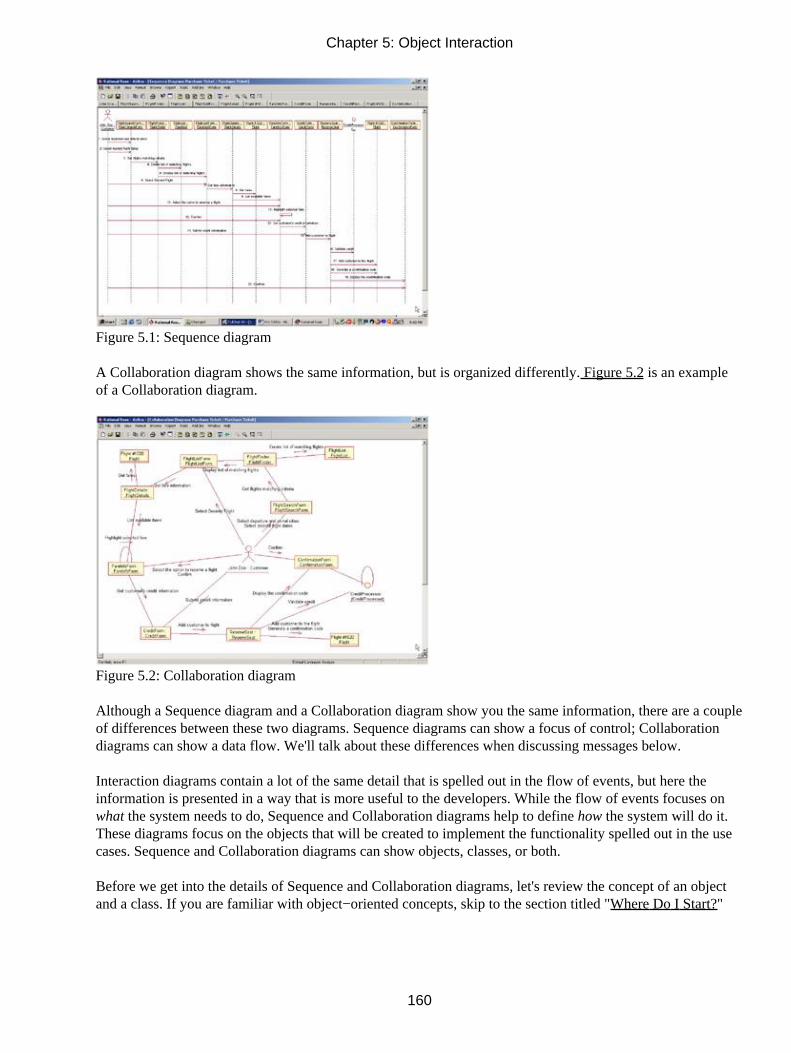
Figure 5.1: Sequence diagram
A Collaboration diagram shows the same information, but is organized differently. Figure 5.2 is an exampleof a Collaboration diagram.
Figure 5.2: Collaboration diagram
Although a Sequence diagram and a Collaboration diagram show you the same information, there are a coupleof differences between these two diagrams. Sequence diagrams can show a focus of control; Collaborationdiagrams can show a data flow. We'll talk about these differences when discussing messages below.
Interaction diagrams contain a lot of the same detail that is spelled out in the flow of events, but here theinformation is presented in a way that is more useful to the developers. While the flow of events focuses onwhat the system needs to do, Sequence and Collaboration diagrams help to define how the system will do it.These diagrams focus on the objects that will be created to implement the functionality spelled out in the usecases. Sequence and Collaboration diagrams can show objects, classes, or both.
Before we get into the details of Sequence and Collaboration diagrams, let's review the concept of an objectand a class. If you are familiar with object−oriented concepts, skip to the section titled "Where Do I Start?"
Chapter 5: Object Interaction
160

What Is an Object?
We see objects all around us. The chair you're sitting in, the book you're reading, and the lightbulb that'shelping you see are all examples of objects in the real world. An object in the software world is very much thesame.
An object is something that encapsulates information and behavior. It's a term that represents some concrete,real−world thing. Examples of objects are:
• Flight #1020
• The house at 7638 Main Street
• The yellow flower just outside my kitchen window
In the airline example, some of the objects would include an airplane, a flight, a passenger, a piece of luggage,or a ticket.
Every object encapsulates some information and some behavior. There might be a flight #1020 object, forexample, that has some information: The departure date is May 24, the departure time is 9:40 p.m., the flightnumber is 1020, and the departure city is Los Angeles. The flight object also has some behavior: It knowshow to add a passenger to the flight, remove a passenger from the flight, and determine when it is full.
The pieces of information held by an object are known as its attributes. Although the values of the attributeswill change over time (flight 1020 will have a departure date of May 25 the next day), the attributesthemselves will not change. Flight 1020 will always have a departure date, a departure time, a flight number,and a departure city.
The behaviors an object has are known as its operations. In this case, the operations for the flight includeadding a passenger, removing a passenger, and checking to see when the flight is full. In Rose, objects areadded to the Interaction diagrams. When dragging an actor (which in Rose is a class stereotype) or some otherclass onto an Interaction diagram, an object instantiation of that class will automatically be created. Removingan object from a diagram in Rose will not delete the class from the model.
What Is a Class?
A class is something that provides a blueprint for an object. In other words, a class defines what informationan object can hold and what behavior it can have. For example, classes for flight #1020, the house at 7638Main Street, and the yellow flower just outside my kitchen window would be: Flight, House, and Flower. TheHouse class would just specify that a house has a height, width, number of rooms, and square footage. TheHouse at 7638 Main Street object might have a height of 40 feet, a width of 60 feet, 10 rooms, and 2000square feet. A class is a more generic term that simply provides a template for objects.
Chapter 5: Object Interaction
161

Think of a class as a blueprint for a house, and the objects as the 25 houses that were all built from thatblueprint. We'll talk more about classes in the next chapter.
Where Do I Start?
To create a Sequence or Collaboration diagram, we first go through the flow of events and determine howmany of the flows will need an Interaction diagram. You can create a diagram for just the primary flow or forall the alternate flows and error flows as well. If two alternate or error flows are very similar, they may becombined onto one diagram. The more diagrams you create, the more thorough your exploration of how thesystem should be built and the easier the rest of the steps in the process will be. (Class diagrams, Componentdiagrams, and Deployment diagrams will be covered in the coming chapters.) The trade−off, of course, istime. It can take quite some time to build a detailed Sequence or Collaboration diagram, because great manydesign decisions need to be made at this point.
Patterns can come to the rescue here. You can build patterns for common logic. They include things such asretrieving data from the database, checking the user's security level, error handling and logging, interprocesscommunication, and so on. If you document these patterns in their own Sequence diagrams, it isn't necessaryfor every diagram to show how you check the user's security level; you can simply reference the securitypattern. These types of patterns are also excellent candidates for reuse in other projects.
The steps involved in creating a Sequence or Collaboration diagram are:
• Find the objects.
• Find the actor.
• Add messages to the diagram.
We will discuss each of these steps in the next sections.
Finding Objects
A good way to find some initial objects is to examine the nouns in your flow of events. Another good place tolook is in the scenario documents. A scenario is a specific instance of a flow of events. The flow of events forthe "Purchase Ticket" use case has several scenarios. For example, John Doe purchases a ticket for flight#1020; John requests and gets a frequent−flyer ticket for flight #1020; John requests a frequent−flyer ticketfor flight #1020, but there are no seats available; John requests a frequent−flyer ticket for flight #1020, but hedoes not have enough frequent−flyer miles. More scenarios would be developed to explain exceptions, such aswhat happens if there's a problem with the credit card, if John is already booked for flight #1020, or if thecredit system can't be accessed. Any exceptions like these that should be programmed into the system should
Chapter 5: Object Interaction
162

be captured in the flow of events and on a Sequence or Collaboration diagram.
Most use cases will have a number of Sequence and Collaboration diagrams, one for each scenario throughthe flow of events. These diagrams can be built at a high level of abstraction, to show how systemscommunicate, or at a very detailed level, showing exactly what classes need to participate in a particularscenario.
As you look at the nouns in your scenarios, some of the nouns will be actors, some will be objects, and somewill be attributes of an object. When you're building your Interaction diagrams, the nouns will tell you whatthe objects will be. If you're looking at a noun and wondering whether it's an object or an attribute, askwhether it has any behavior. If it's information only, it's probably an attribute. If it has some behaviors also, itmay be an object. Another check is whether it has attributes of its own. Is a passenger an attribute of a flightor an object of its own? The answer to that question really depends on the application you are building. If allyou need to store is the name of the passenger, then it can be modeled as an attribute of a flight. If, however,you also want to store the passenger's address, credit card information, and phone number, then it would bebetter modeled as a separate object.
Not all of the objects will be in the flow of events. Forms, for example, may not appear in the flow of events,but will have to appear on the diagram in order to allow the actor to enter or view information. Other objectsthat probably won't appear in the flow of events are control objects.
You should consider each of these categories as you identify objects:
Entity objects These are objects that hold information. They may eventually map to some of the tables andfields in the database. Many of the nouns in the flow of events will give you entity objects. Entity objects inour airline example might be flight #1020, passenger John Doe, or ticket #1347A. These are business entitiesthat have meaning to the end user.
Boundary objects These are objects that lie on the boundary between the system and the outside world. Inother words, these are the forms and windows of the application and the interfaces to other applications.Forms may appear in the flow of events, but interfaces probably won't. As you go through the logic in theflow of events, ask whether any other system will need to be involved to carry out the logic in the flow. If so,you may need one or more interface objects.
Control objects These are optional objects that control the flow through the use case. They don't carry outany business functionality in and of themselves. Instead, they coordinate the other objects and control theoverall logic flow. For example, a control object would know that the user's security level should be checkedbefore a particular report is run. The control object wouldn't check the security level or run the report, itsimply holds the sequencing logic and the business rules for the scenario. It would first tell another object tocheck the security, and then tell the report to run. Control objects won't appear in the flow of events. Usingthem is, instead, a design decision; if you decide to use control objects, add one to your Sequence orCollaboration diagram.
Finding the Actor
Once you have identified the objects for your Interaction diagram, the next step is to identify the necessaryactor. An actor on an Interaction diagram is the external stimulus that starts the workflow for a flow of events.You can identify the actor by looking at the flow of events and determining who or what starts the process.
There may be more than one actor for a given Interaction diagram. Each actor that receives a message from orsends a message to the system in a particular scenario should be shown on the diagram for that scenario.
Chapter 5: Object Interaction
163

Using Interaction Diagrams
From the diagrams, designers and developers can determine the classes they will need to develop, therelationships between the classes, and the operations or responsibilities of each class. The Interactiondiagrams become the cornerstones upon which the rest of the design is built.
Sequence diagrams are ordered by time. They are useful if someone wants to review the flow of logic througha scenario. Although Collaboration diagrams include sequencing information, it is easier to see on a Sequencediagram.
Collaboration diagrams are useful if you want to assess the impact of a change. It's very easy to see on aCollaboration diagram which objects communicate with which other objects. If you need to change an object,you can easily see which other objects might be affected.
Interaction diagrams contain:
Objects An Interaction diagram can use object names, class names, or both.
Messages Through a message, one object or class can request that another carry out some specific function.For example, a form may ask a report object to print itself.
One thing to remember as you create the Interaction diagrams is that you are assigning responsibility toobjects. When you add a message to an Interaction diagram, you are assigning a responsibility to the objectreceiving the message. Be sure to assign the appropriate responsibilities to the appropriate objects. In mostapplications, screens and forms shouldn't do any business processing. They should only allow the user to enterand view information. By separating the front−end from the business logic, you've created an architecture thatreduces the ripple effect of changes. If the business logic needs to change, the interface shouldn't be affected.If you change the format of a screen or two, the business logic won't need to be changed. Other objects shouldbe assigned appropriate responsibilities as well. For example, if you need to print a list of all flights in anairline's schedule, flight #1020 shouldn't be responsible for that. The responsibilities of the flight #1020 objectshould focus on just that flight. Another object can be responsible for looking at all of the flights in order togenerate a report.
Another way to look at responsibilities is to consider the entity, boundary, and control categories we discussedearlier in the "Finding Objects" section. Entity objects should hold information and conduct businessfunctionality. Boundary classes (forms and windows) should display and receive information, but should alsodo minimal business processing. Boundary classes (interfaces) should send information to another system orreceive information from another system, but again do minimal business processing. Control classes shouldtake care of the sequencing.
Sequence Diagrams
Let's begin by taking a look at Sequence diagrams. Sequence diagrams are Interaction diagrams that areordered by time; you read the diagram from the top to the bottom. As we mentioned above, each use case willhave a number of alternate flows. Each Sequence diagram represents one of the flows through a use case. Forexample, Figure 5.3 is the Sequence diagram that shows John Doe purchasing a ticket for flight #1020.
Chapter 5: Object Interaction
164

We can read this diagram by looking at the objects and messages. The objects that participate in the flow areshown in rectangles across the top of the diagram. In this example, there are a number of objects: the flightsearch form, flight list form, fare information form, credit form, and confirmation form are all client pagesthat are displayed to the end user. The remaining objects constitute the server−side logic and include serverpages, interfaces, and other server−side objects. Notice that some of the objects have the same name as theirclasses. It is not necessary to name the objects differently from the classes.
Figure 5.3: Sequence diagram for purchasing a ticket
The process begins when John Doe selects his departure and destination cities and departure and return dates.The FlightFinder server−side object looks for flights that match the criteria and builds the FlightListForm,which displays all matching flights. John selects his flight, and the FlightDetails server−side object looks forfare information for that flight. Once fare information has been retrieved, it is displayed using theFareInfoForm. John confirms the rate, and the CreditForm is displayed. John enters his credit information, andthe CreditProcessor object interfaces to the external credit system to confirm John's credit. Once the credit hasbeen confirmed, a seat is reserved, the confirmation number is generated, and the confirmation is displayed toJohn.
Each object has a lifeline, drawn as a vertical dashed line below the object. The lifeline begins when the objectis instantiated and ends when the object is destroyed. A message is drawn between the lifelines of two objectsto show that the objects communicate. Each message represents one object making a function call of another.Later in the process, as we define operations for the classes, each message will become an operation.Messages can also be reflexive, showing that an object is calling one of its own operations.
The Sequence Diagram Toolbar
When a Sequence diagram is opened, the Diagram toolbar changes to let you add objects, messages, and otheritems to the diagram. Table 5.1 lists the buttons available in the Sequence Diagram toolbar and explains thepurpose of each. In the following sections, we'll discuss adding each of these items.
Table 5.1: Icons in the Sequence Diagram Toolbar
Icon Button Purpose
Selects or Deselects an Item Returns the cursor to an arrow to select an item.
Chapter 5: Object Interaction
165

Text Box Adds a text box to the diagram.
Note Adds a note to the diagram.
Anchor Note to Item Connects a note to an item in the diagram.
Object Adds a new object to the diagram.
Object Message Draws a message between two objects.
Message to Self Draws a reflexive message.
Return Message Shows a return from a procedure call.
Destruction Marker Shows when an object is destroyed.
Procedure Call Draws a procedure call between two objects.
Asynchronous Message Draws an asynchronous message between two objects.
Collaboration Diagrams
Like Sequence diagrams, Collaboration diagrams are used to show the flow through a specific scenario of ause case. While Sequence diagrams are ordered by time, Collaboration diagrams focus more on therelationships between the objects. Figure 5.4 is the Collaboration diagram for John Doe purchasing a ticket forflight #1020.
Figure 5.4: Collaboration diagram for John purchasing a ticket
As you can see, the information that was in the Sequence diagram in Figure 5.3 is still here in theCollaboration diagram, but this diagram gives us a different view of the flow. In this diagram, it's easier to seethe relationships between the objects. However, it's a little more difficult to see the sequencing information.
For this reason, you may want to create both a Sequence and a Collaboration diagram for a scenario. Althoughthey serve the same purpose and contain the same information, each gives you a slightly different view. InRose, you can create a Sequence diagram from a Collaboration diagram (or vice−versa) either by pressing F5or selecting Browse → Create (Sequence/Collaboration) Diagram.
Chapter 5: Object Interaction
166

The Collaboration Diagram Toolbar
The Collaboration diagram toolbar is very similar to the Sequence diagram toolbar. There are a few optionsavailable here that aren't available in a Sequence diagram, such as an object link and data flows. Thefollowing sections describe how to use each of these toolbar buttons to add items to the diagram. Table 5.2shows the toolbar buttons available on the Collaboration diagram toolbar.
Table 5.2: Icons in the Collaboration Diagram Toolbar
Icon Button Purpose
Selects or Deselects an Item Returns the cursor to an arrow to select an item.
Text Box Adds a text box to the diagram.
Note Adds a note to the diagram.
Anchor Note to Item Connects a note to an item on the diagram.
Object Adds a new object to the diagram.
Class Instance Adds a new class instance to the diagram.
Object Link Creates a path for communication between two objects.
Link to Self Shows that an object can call its own operations.
Link Message Adds a message between two objects or from an object to itself.
Reverse Link Message Adds a message in the opposite direction between two objects orfrom an object to itself.
Data Token Shows information flow between two objects.
Reverse Data Token Shows information flow in the opposite direction between twoobjects.
Working with Actors on an Interaction Diagram
Most Sequence and Collaboration diagrams have an actor object. The actor object is the external stimulus thattells the system to run some functionality. The actor objects for the Interaction diagram will include the actorsthat interact with the use case on the Use Case diagram.
To create an actor object on an Interaction diagram:
1. Open the Interaction diagram.
2. Select the actor in the browser.
3. Drag the actor from the browser to the open diagram.
To remove an actor object from an Interaction diagram:
1.
Chapter 5: Object Interaction
167

Select the actor on the Interaction diagram.
2. Select Edit → Delete from Model, or press Ctrl+D.
Note Deleting an actor from the diagram does not delete the actor from the model.
Working with Objects
The Sequence and Collaboration diagrams show you the objects that participate in one flow through aparticular use case. Once the actor object has been added to the diagram, the next step is to add other objects.As we discussed above, you can find the objects that participate in a particular Sequence or Collaborationdiagram by examining the nouns in the flow of events and scenario documents. After this step, we will go inand add the messages between the objects.
Adding Objects to an Interaction Diagram
One of the first steps in creating a Sequence or a Collaboration diagram is adding the objects. Look at thenouns from your flow of events and scenarios to start finding objects.
To add an object to a Sequence diagram:
1. Select the Object toolbar button.
2. Click in the location on the diagram where you want the object to reside. In a Sequence diagram,objects are arranged in a row near the top.
Note In Rose 2001A and 2002, you can move an object down from the top to the point at which it iscreated.
3. Type the name of the new object.
4. Once you have added the objects, you can rearrange them by dragging and dropping. You can insertan object between two existing objects by clicking between the two existing objects in step two.
To add an object to a Collaboration diagram:
1. Select the Object toolbar button.
2. Click in the location on the diagram where you want the object to reside. In a Collaboration diagram,objects can be located anywhere.
3. Type the name of the new object.
Chapter 5: Object Interaction
168

Deleting Objects from an Interaction Diagram
As you build your Interaction diagrams, you may need to delete some of the objects. When you delete anobject from the diagram, Rose will automatically delete any messages that start or end with that object andautomatically renumber all of the remaining messages.
When you delete an object from a Sequence diagram, Rose will automatically delete the object from theCollaboration diagram but will not delete the corresponding class from the model. Similarly, when you deletean object from a Collaboration diagram, Rose will remove it from the Sequence diagram. If you change yourmind, you can use the Undo option on the Edit menu.
To remove an object from a Sequence or Collaboration diagram:
1. Select the object in the Sequence or Collaboration diagram.
2. Select Edit → Delete from Model, or press Ctrl+D.
Note Deleting an object from the diagram does not delete the corresponding class from the model.If you have several copies of an object on a single diagram and all copies have the same name and the sameclass, you can press Delete to remove one copy of the object. Pressing Ctrl+D or selecting Delete from Modelwill remove all copies.
Setting Object Specifications
There are a number of different fields that Rose provides to add some detail to the objects in your diagram.For example, you can set the object's name, its class, its persistence, and whether there are multiple instancesof the object. You can also add documentation to the object in the object specification window, shown inFigure 5.5. Adding documentation to an object does not add the documentation to the class, and addingdocumentation to an object on one diagram does not add the documentation to the object on other diagrams.In the following sections, we'll take a look at each of the options available on the object specification window.
Chapter 5: Object Interaction
169

Figure 5.5: Object specification window
To open the object specifications:
1. Right−click the object in the Sequence or Collaboration diagram.
2. Select Open Specification from the shortcut menu.
OR
1. Select the object in the Sequence or Collaboration diagram.
2. Select Browse → Specification, or press Ctrl+B.
Naming an Object
Each object on a Sequence or Collaboration diagram should be given a unique name. However, for readabilityyou may have multiple copies of a single object on the diagram, and in this case each copy will have the samename. While class names are very generic (Employee and Company, for example), object names are veryspecific (John Doe and Rational Software Corporation). On an Interaction diagram, you may have two objectsthat are instances of the same class. For example, in an inventory system, you may have one instance of a Partclass, called Engine, which communicates with another instance of Part, called Carburetor. You can enter thename of each object on the diagram in the object specification window, or directly on the diagram.
To name an object:
1.
Chapter 5: Object Interaction
170

Right−click the object in the Sequence or Collaboration diagram.
2. Select Open Specification from the shortcut menu.
3. In the Name field, enter the object's name. You may also use this field to change the name of theobject later on.
OR
1. Select the object in the Sequence or Collaboration diagram.
2. Right−click so that a cursor shows up in the object.
3. Type the object name.
To add documentation to an object:
1. Right−click the object in the Sequence or Collaboration diagram.
2. Select Open Specification from the shortcut menu.
3. In the Documentation field, you can enter documentation for the object.
OR
1. Select the object in the Sequence or Collaboration diagram.
2. Type the object documentation in the documentation window.
Mapping an Object to a Class
On a Sequence or Collaboration diagram, each object may be mapped to a class. For example, flight #1020may be mapped to a class called Flight. In the object specification window, you can use the Class field to setthe object's class. By default, the class will be set to (Unspecified).
When selecting a class for the object, you can either use an existing class from your model or create a newclass for the object. In the procedures below, we describe both of these approaches.
By the time you are ready to generate code, all of the objects should be mapped to classes. To map an objectto an existing class:
1.
Chapter 5: Object Interaction
171

Right−click the object in the Interaction diagram.
2. Select Open Specification from the shortcut menu.
3. In the Class drop−down list box, type the class name or select an option from the drop−down list box.
4. Once you have mapped the object to a class, the class name will appear with the object name on thediagram, preceded by a colon. You can toggle the display of the class name by right−clicking theobject and selecting Show Class.
OR
1. Select the class in the Logical view of the browser.
2. Drag the class from the browser to the object in the diagram.
3. Once you have mapped the object to a class, the class name will appear with the object name on thediagram, preceded by a colon:
To remove an object's class mapping:
1. Right−click the object in the Sequence or Collaboration diagram.
2. Select Open Specification from the shortcut menu.
3. In the Class drop−down list box, select (Unspecified).
To create a new class for the object:
1. Right−click the object in the Sequence or Collaboration diagram.
2. Select Open Specification from the shortcut menu.
3.
Chapter 5: Object Interaction
172

Select <New> in the Class drop−down list box. Rose will take you to the specification window for thenew class.
To ensure all objects have been mapped to classes:
1. Select Report → Show Unresolved Objects.
2. Rose will display a list of all objects in the model that have not yet been mapped to a class.
To show only the object name on the diagram:
1. Right−click the object in the Sequence or Collaboration diagram.
2. De−select Show Class.
To show both the object and class name on the diagram:
1. Right−click the object in the Sequence or Collaboration diagram.
2. Select Show Class.
To show only the class name on the diagram:
1. If you would rather use only the class name, and not see the object's name at all on the diagram,right−click the object in the Sequence or Collaboration diagram.
2. Select Open Specification from the shortcut menu.
3. Delete the object name from the Name field. Rose will display the object using only the class name.Again, the class name is preceded by a colon.
Setting Object Persistence
In Rose, you can set the persistence option for each object in the diagram. Rose provides you with three
Chapter 5: Object Interaction
173
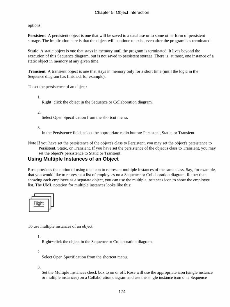
options:
Persistent A persistent object is one that will be saved to a database or to some other form of persistentstorage. The implication here is that the object will continue to exist, even after the program has terminated.
Static A static object is one that stays in memory until the program is terminated. It lives beyond theexecution of this Sequence diagram, but is not saved to persistent storage. There is, at most, one instance of astatic object in memory at any given time.
Transient A transient object is one that stays in memory only for a short time (until the logic in theSequence diagram has finished, for example).
To set the persistence of an object:
1. Right−click the object in the Sequence or Collaboration diagram.
2. Select Open Specification from the shortcut menu.
3. In the Persistence field, select the appropriate radio button: Persistent, Static, or Transient.
Note If you have set the persistence of the object's class to Persistent, you may set the object's persistence toPersistent, Static, or Transient. If you have set the persistence of the object's class to Transient, you mayset the object's persistence to Static or Transient.
Using Multiple Instances of an Object
Rose provides the option of using one icon to represent multiple instances of the same class. Say, for example,that you would like to represent a list of employees on a Sequence or Collaboration diagram. Rather thanshowing each employee as a separate object, you can use the multiple instances icon to show the employeelist. The UML notation for multiple instances looks like this:
To use multiple instances of an object:
1. Right−click the object in the Sequence or Collaboration diagram.
2. Select Open Specification from the shortcut menu.
3. Set the Multiple Instances check box to on or off. Rose will use the appropriate icon (single instanceor multiple instances) on a Collaboration diagram and use the single instance icon on a Sequence
Chapter 5: Object Interaction
174

diagram.
Working with Messages
A message is a communication between objects in which one object (the client) asks another object (thesupplier) to do something. By the time you generate code, a message will translate to a function call. In thisexample, one form is asking another to display itself:
Adding Messages to an Interaction Diagram
Once you have placed the objects on your Sequence or Collaboration diagram, the next step is to add themessages sent between the objects. On a Sequence diagram, messages can be added by drawing an arrowbetween the lifelines of two objects. On a Collaboration diagram, you must first add a link between twoobjects. Then you can add messages to the link.
Adding Messages to a Sequence Diagram
In a Sequence diagram, messages are drawn between the lifelines of the objects or from an object's lifeline toitself. Messages are shown in chronological order, from the top of the diagram to the bottom.
To add a message to a Sequence diagram:
1. Select the Object Message button from the toolbar.
2. Drag the mouse from the lifeline of the object or actor sending the message to the object or actorreceiving the message, as shown in Figure 5.6.
Figure 5.6: Adding a message to a Sequence diagram
3.
Chapter 5: Object Interaction
175

Type in the text of the message.
To add a reflexive message to a Sequence diagram:
1. Select the Message to Self toolbar button.
2. Click on the lifeline of the object sending and receiving the message, as shown in Figure 5.7.
Figure 5.7: Adding a reflexive message to a Sequence diagram
3. With the new message still selected, type in the text of the message.
Deleting Messages from a Sequence Diagram
As you work on your Sequence diagram, you may need to delete some of the messages that you've drawn. Ifyou delete a message, Rose will automatically renumber all of the remaining messages.
To delete a message from a Sequence diagram:
1. Select the message to be deleted.
2. Select Edit → Delete from Model, or press Ctrl+D.
Reordering Messages in a Sequence Diagram
At times, you may want to reorder the messages in your Sequence diagram. In Rose, reordering messages isvery easy to do; you simply drag and drop the message into its new location. As the messages are reordered,they will automatically be renumbered.
To reorder the messages in a Sequence diagram:
1. Select the message to be moved (select the arrow, not the text).
2.
Chapter 5: Object Interaction
176
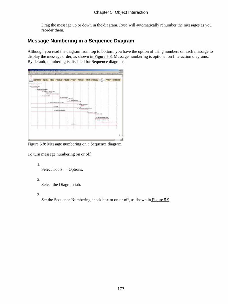
Drag the message up or down in the diagram. Rose will automatically renumber the messages as youreorder them.
Message Numbering in a Sequence Diagram
Although you read the diagram from top to bottom, you have the option of using numbers on each message todisplay the message order, as shown in Figure 5.8. Message numbering is optional on Interaction diagrams.By default, numbering is disabled for Sequence diagrams.
Figure 5.8: Message numbering on a Sequence diagram
To turn message numbering on or off:
1. Select Tools → Options.
2. Select the Diagram tab.
3. Set the Sequence Numbering check box to on or off, as shown in Figure 5.9.
Chapter 5: Object Interaction
177

Figure 5.9: Message numbering check box
Viewing the Focus of Control in a Sequence Diagram
In a Sequence diagram, you have the option of showing the focus of control, which lets you know whichobject has control at a particular point in time. As shown in Figure 5.10, a small rectangle represents the focusof control. This is one of the differences between a Sequence and a Collaboration diagram; the focus ofcontrol is shown only on a Sequence diagram.
Figure 5.10: Focus of control on a Sequence diagram
To turn the focus of control on or off:
1. Select Tools → Options.
2. Select the Diagram tab.
3.
Chapter 5: Object Interaction
178

Set the Focus of Control check box to on or off, as shown in Figure 5.11.
Figure 5.11: Focus of Control check box
Adding Messages to a Collaboration Diagram
Before you can add messages to a Collaboration diagram, you have to establish a path of communicationbetween two objects. This path is called a link, and is created using the Object Link toolbar button. Once thelink has been added, you can add messages between the objects.
To add a message to a Collaboration diagram:
1. Select the Object Link toolbar button.
2. Drag from one object to the other to create the link.
3. Select the Link Message or Reverse Link Message toolbar button.
4. Click the link between the two objects. Rose will draw the message arrow, as shown in Figure 5.12.
Figure 5.12: Adding a message to a Collaboration diagram
5. With the new message selected, type the text of the message.
To add a reflexive message to a Collaboration diagram:
1.
Chapter 5: Object Interaction
179

Select the Link to Self toolbar button.
2. Click the object sending and receiving the message. Rose will draw a reflexive link on the object. Itwill appear above the object and look like a half−circle.
3. Select the Link Message toolbar button.
4. Click the object's reflexive link. Rose will add the message arrow, as shown in Figure 5.13.
Figure 5.13: Adding a reflexive message to a Collaboration diagram
5. With the new message still selected, enter the text of the message.
Note If you are adding more than one reflexive message to an object in a Collaboration diagram, skip stepsone and two for each additional message.
Deleting Messages from a Collaboration Diagram
As with Sequence diagrams, you can delete messages from a Collaboration diagram. When you delete amessage, Rose will automatically renumber the remaining messages.
To delete a message from a Collaboration diagram:
1. Select the message to delete.
2. Select Edit → Delete From Model, or press Ctrl+D.
Chapter 5: Object Interaction
180

Message Numbering in a Collaboration Diagram
With a Sequence diagram, you know that you read the diagram from top to bottom, so message numberingisn't necessary. A Collaboration diagram, however, loses its sequencing information if you remove themessage numbering.
You do have the option in Rose of turning off message numbering in a Collaboration diagram. To turnmessage numbering on or off:
1. Select Tools → Options.
2. Select the Diagram tab.
3. Set the Collaboration and Sequence Numbering check box to on or off.
Adding Data Flows to a Collaboration Diagram
We mentioned earlier that one of the differences between a Sequence and a Collaboration diagram is the useof the focus of control. The other difference is in the use of data flow. Collaboration diagrams show dataflows; Sequence diagrams do not.
Data flows are used to show the information that is returned when one object sends a message to another. Ingeneral, you don't add data flows to every message on a Collaboration diagram, because it can clutter thediagram with information that's not really valuable. If a message just returns a comment such as "OK, themessage was received and everything worked fine" or "Oops! There was an error in running the requestedfunction," it's probably not worth showing on the diagram. But if a message returns a structure, say a list ofemployees working for the company, this may be significant enough to show on a diagram.
When you eventually map each message to an operation of a class, the information in the data flows will beadded to the operation's details. As a general rule, don't waste too much time worrying about data flows now.Add them to the diagram if you think they're significant enough to help the developers. If not, leave them out.
To add a data flow to a Collaboration diagram:
1. Select the Data Token or Reverse Data Token toolbar button.
2. Click on the message that will be returning data. Rose will automatically add the data flow arrow tothe diagram, as shown in Figure 5.14.
Figure 5.14: Adding a data flow to a Collaboration diagram
3.
Chapter 5: Object Interaction
181

With the new data flow still selected, type in the data that will be returned.
Setting Message Specifications
In Rose, you can set a number of different options to add detail to each message. As with use cases and actors,you can add names and documentation to messages. You can also set synchronization and frequency options.In this section, we'll discuss each of the options you can set for a message.
To open the message specifications:
Double−click the message on the diagram. The message specification window will appear, as shown in Figure5.15.
Figure 5.15: Message specification window
OR
1. Select the message on the diagram.
2. Select Browse → Specification, or press Ctrl+B.
Naming a Message
In the message specification window, you can name the message or change the name, and add documentation.Each message should have a name that indicates the purpose of the message. Later, as you map each of themessages to operations, the message name will be replaced with the operation name.
Chapter 5: Object Interaction
182

To name a message:
1. Double−click the message on the Sequence or Collaboration diagram.
2. If you have mapped the receiving object to a class, the operations of that class will appear in theName drop−down list box. Select an entry from the list or type in the name of the message.
OR
1. Select the message on the Sequence or Collaboration diagram.
2. Type the message name.
Note If you have mapped the receiving object to a class, the name of the receiving class will appear next tothe name, in the Class field. This field cannot be modified. To change the receiving class, map theobject to another class in the object specification window.
To add documentation to a message:
1. Double−click the message to open the message specification window.
2. In the Documentation area, enter comments for the message. You may, for example, want to enter alittle bit of pseudocode that describes what the message will do.
OR
1. Select the message on the Sequence or Collaboration diagram.
2. Enter comments in the Documentation window.
Mapping a Message to an Operation
Before you generate code, each message on your Sequence and Collaboration diagrams should be mapped toan operation of a class. In this example, the message "Request Some Functionality" will be mapped to anoperation of the Supplier class.
Chapter 5: Object Interaction
183

To map a message to an existing operation:
1. Be sure the receiving object (the supplier) has been mapped to a class.
2. Right−click the message in the Sequence or Collaboration diagram.
3. A list of the supplier's operations will appear.
4. Select the operation from the list, as shown in Figure 5.16.
Figure 5.16: Mapping a message to an existing operation
To remove a message's operation mapping:
1. Double−click the message in the Sequence or Collaboration diagram.
2. In the Name field, delete the operation name and enter the new message name.
To create a new operation for the message:
1. Be sure the receiving object (the supplier) has been mapped to a class.
2. Right−click the message in the Sequence or Collaboration diagram.
3. Select <new operation>.
4. Enter the new operation's name and details. (The options available on the operation specificationwindow are discussed in detail in Chapter 7, "Attributes and Operations.")
5. Click OK to close the operation specification window and add the new operation.
6.
Chapter 5: Object Interaction
184

Right−click the message.
7. Select the new operation from the list that appears.
To ensure each message has been mapped to an operation:
1. Select Report → Show Unresolved Messages.
2. Rose will display a list of all messages that have not yet been mapped to operations.
Setting Message Synchronization Options
In the Detail tab of the message specification window, as shown in Figure 5.17, you can specify theconcurrency of the message being sent.
Figure 5.17: Setting synchronization options
The arrows on the diagram will change if you set the concurrency to Balking, Timeout, or Asynchronous. Youhave seven synchronization options:
Simple This is the default value for messages. This option specifies that the message runs in a single threadof control. On the Sequence diagram, simple messages use this symbol:
Chapter 5: Object Interaction
185

Synchronous Use this option when the client sends the message and waits until the supplier has acted uponthe message. On the Sequence diagram, synchronous messages will appear this way:
Balking With this option, the client sends the message to the supplier. If the supplier is not immediatelyready to accept the message, the client abandons the message. On the Sequence diagram, balking messagesappear like this:
Timeout Using this option, the client sends the message to the supplier and waits a specified amount oftime. If the supplier isn't ready to receive the message in that time, the client abandons the message. On theSequence diagram, timeout messages appear using this arrow:
Asynchronous With this option, the client sends the message to the supplier. The client then continuesprocessing, without waiting to see if the message was received or not. On the Sequence diagram,asynchronous messages look like this:
Chapter 5: Object Interaction
186

Procedure Call With this option, the client sends the message to the supplier. The client then must waituntil the entire nested sequence of messages is processed before continuing. On the Sequence diagram,procedure call messages look like this:
Return This option indicates the return from a procedure call. On the Sequence diagram, return messageslook like this:
To set the message synchronization:
1. Double−click the message on the Sequence or Collaboration diagram.
2. In the message specification window, select the Detail tab.
3. Select the desired synchronization option from the radio buttons in the window.
Chapter 5: Object Interaction
187

Setting Message Frequency
Message frequency lets you mark a message to be sent at regular intervals. Say, for example, you have amessage that should run once every 30 seconds. You can set that message to be periodic. The frequencyoptions are available in the Detail tab of the message specification window, as shown in Figure 5.18.
Figure 5.18: Setting message frequency
There are two frequency options:
Periodic This option suggests that the message is sent on a regular, periodic basis.
Aperiodic This option suggests that the message is not sent on a regular basis. It may be sent only once orat irregular points in time.
Note Message frequency will not change the appearance of the Sequence or Collaboration diagram.To set the message frequency:
1. Double−click the message in the Sequence or Collaboration diagram.
2. In the message specification window, select the Detail tab.
3. Select the desired frequency option from the radio buttons in the lower part of the window.
Chapter 5: Object Interaction
188

End of a Lifeline
Rose 2001A and 2002 give you greater control over the display of an object's lifeline on a Sequence diagram.Specifically, they give you the ability to position an object at the point at which it is instantiated and theability to add a destruction marker to indicate when the object is destroyed.
Let's first look at the beginning of the lifeline. As a scenario progresses, objects will be created and destroyed.In Rose 2001A and 2002, you can move an object vertically to indicate where it is created:
You can also indicate when an object is removed from memory. This can be especially helpful in optimizing adesign, because it gives you a quick way to see when memory is "cleaned up" in a specific scenario.
The destruction marker is used to indicate the end of a lifeline. It appears as an "X" on the lifeline itself, andthe lifeline will not extend beyond it:
To add a lifeline:
1. Select the Destruction Marker icon from the toolbar.
2. Click on the object's lifeline, at the point where it is removed from memory.
Working with Scripts
In Rose, notes are typically used to add a comment to an object. Scripts, on the other hand, are usually used to
Chapter 5: Object Interaction
189

add a comment to a message. Scripts are only used on Sequence diagrams. They are usually placed on the leftside of the diagram, opposite the message they refer to.
You can use a script to clarify the meaning of a message. You may have a message that reads "Validate User."In the script, you can expand on the meaning: "Validate the ID to be sure that the user exists and that thepassword is correct."
You can also use scripts to enter some conditional logic in your diagram. Figure 5.19 illustrates some samplescripts in a Sequence diagram.
Figure 5.19: Using scripts in a Sequence diagram
In general, try to avoid putting so much conditional logic on the diagram that the diagram loses its simplicity.By the time you add the details of a nested If statement inside a nested If statement inside a nested Ifstatement, your diagram will probably be cluttered. On the other hand, there are times when you need to showa little bit of conditional logic. Just balance the two extremes. As long as the diagram is easily readable andunderstandable, you should be fine. If the conditional logic gets too complicated, just create additionalSequence diagrams: one to deal with the if part, one to deal with the else part, and so on.
Besides If statements, you can use scripts to show loops and other pseudocode on your diagram. Scripts won'tgenerate any code, but they will let the developers know how the logic is intended to flow.
To add a script to a Sequence diagram:
1. Select the Text Box toolbar button.
2. Click in the location on the diagram where you want the script to reside. Usually this is near the leftedge of the diagram.
3. With the text box selected, type the text of the script.
4.
Chapter 5: Object Interaction
190

Select the text box. Press and hold down Shift and select the message.
5. Select Edit → Attach Script.
6. Now, when you move the message up or down in the diagram, the script will move along with it.
To detach a script from a message:
1. Select the script.
2. Select Edit → Detach Script.
Switching Between Sequence and Collaboration Diagrams
Typically, you create either a Sequence or a Collaboration diagram for a particular scenario. Without amodeling tool like Rose, it can be too time−consuming to create both, especially because both show you thesame information.
In Rose, however, it's very easy to create a Sequence diagram from a Collaboration diagram, or to create aCollaboration diagram from a Sequence diagram. Once you have both a Sequence and a Collaborationdiagram for a scenario, it's very easy to switch between the two.
To create a Collaboration diagram from a Sequence diagram:
1. Open the Sequence diagram.
2. Select Browse → Create Collaboration diagram, or press F5.
3. Rose will create a Collaboration diagram with the same name as the open Sequence diagram.
To create a Sequence diagram from a Collaboration diagram:
1. Open the Collaboration diagram.
2. Select Browse → Create Sequence diagram, or press F5.
3. Rose will create a Sequence diagram with the same name as the open Collaboration diagram.
Chapter 5: Object Interaction
191

To switch between Sequence and Collaboration diagrams:
1. Open the Sequence or Collaboration diagram.
2. Select Browse → Go to (Sequence or Collaboration) Diagram, or press F5.
3. Rose will look for a Sequence or Collaboration diagram with the same name as the open diagram.
Two−Pass Approach to Interaction Diagrams
Frequently, people use a two−pass approach to creating Interaction diagrams. On the first pass, they focus onhigher−level information that the customers will be concerned with. Messages aren't mapped to operationsyet, and objects may not be mapped to classes. These diagrams let just the analysts, customers, and anyoneelse interested in the business flow see how the logic will flow in the system.
The first pass of a Sequence diagram might look like Figure 5.20.
Figure 5.20: First−pass Sequence diagram
In the second pass, once the customers have agreed to the flow from the first−pass diagram, the team addsmore of the detail. The diagram at this point may lose its usefulness to the customer, but will become veryuseful to the developers, testers, and other members of the project team.
To begin, some additional objects may be added to the diagram. Each Interaction diagram may have a controlobject, which is responsible for controlling the sequencing through a scenario. All of the Interaction diagramsfor a use case may share the same control object, so you have one control object that handles all of thesequencing information for the use case.
If you add a control object, your Sequence diagram will typically look something like Figure 5.21.
Chapter 5: Object Interaction
192

Figure 5.21: Sequence diagram with control object
Notice that the control object doesn't carry out any business processing; it just sends off messages to the otherobjects. The control object is responsible for coordinating the efforts of the other objects and delegatingresponsibility. For this reason, control objects are sometimes called manager objects.
The benefit of using a control object is separating the business logic from the sequencing logic. If thesequencing needs to change, only the control object will be affected.
You may also want to add some objects to handle things like security, error handling, or databaseconnectivity. Many of these objects are generic enough to be built once and reused in many applications. Let'stake a look at the database issues, for example.
There are two commonly used options when trying to save information to a database or retrieve informationfrom a database. Say we're trying to save a new employee, John Doe, to the database. The John Doe objectcan either know about the database, in which case it saves itself to the database, or it can be completelyseparated from the database logic, in which case another object has to handle saving John to the database.Let's start with John knowing about the database, as shown in Figure 5.22.
In this situation, there is no separation of application logic and database logic. The John Doe object takes careof application logic, such as hiring and firing John Doe, as well as database logic, including saving John to thedatabase and retrieving him later. Should the database need to change, the change will ripple through more ofthe application this way, because many objects will contain some database logic. On the other hand, thisapproach can be easy to model and implement.
Chapter 5: Object Interaction
193

Figure 5.22: Application logic integrated with database logic
Another option is to separate the application logic from the database logic. In this situation, you will need tocreate another object to deal with the database logic. We'll call this new object Transaction Manager. TheJohn Doe object will still hold the business logic; it will know how to hire or fire John, or how to give him araise. The Transaction Manager object will know how to retrieve John from the database or save him to thedatabase. The Sequence diagram might look something like Figure 5.23.
Figure 5.23: Application logic separated from database logic
The advantage of this approach is that now it's easier to reuse the John Doe object in another application witha different database, or with no database at all. It also helps minimize the impact of a requirement change.Database changes won't affect the application logic, and application changes won't affect the database logic.The disadvantage here can be that you'll need a little more time to model and implement this solution.
These are two of the more common approaches, although there are some other approaches you can take whendealing with database issues. Whichever decision you make, be sure to keep the approach consistent acrossInteraction diagrams.
Aside from database issues, you may add objects now for things like error handling, security, or interprocesscommunication. These details won't interest the customer, but will be critical for the developers.
Chapter 5: Object Interaction
194

Once you've added all of the objects, the next step is to map each of the objects to classes. You can map theobjects to existing classes or create new classes for the objects (see the earlier section titled "Mapping anObject to a Class"). Then, you map each of the messages in the diagram to an operation (see the earlier sectiontitled "Mapping a Message to an Operation"). Finally, you go into the object and message specifications if youneed to set things like object persistence, message synchronization, and message frequency.
Exercise
In this exercise, we'll build a Sequence and a Collaboration diagram to add an item to the shopping cart in ourweb−based e−commerce system.
Problem Statement
After talking with April and building the system use case model, Andy began looking at the particularfunctionality that the system would have to perform. Andy started a detailed analysis of the features needed.The "Add Item to Shopping Cart" use case was one with a higher priority to the users and one with a higherelement of risk. To allow plenty of time to deal with the risks of this use case, Andy decided to tackle it firstby creating a Sequence and a Collaboration diagram.
Create Interaction Diagrams
Create the Sequence diagram and Collaboration diagram to add an item to the shopping cart. Your completedSequence diagram should look like Figure 5.24.
Figure 5.24: Sequence diagram to add an item to the shopping cart
This is just one of the diagrams you would need to model the full "Add Item to Shopping Cart" use case. Thisdiagram shows what happens when everything goes right. You would need some additional diagrams to
Chapter 5: Object Interaction
195

model what happens when things go wrong, or when the user selects different options. Each alternate flow inthe use case may be modeled in its own Interaction diagram.
Exercise Steps:
Setup
1. Select Tools → Options.
2. Select the Diagram tab.
3. Be sure that Sequence Numbering, Collaboration Numbering, and Focus of Control are all checked.
4. Click OK to exit the Options window.
Create the Sequence Diagram
1. Right−click Add Item to Shopping Cart in the system use case model in the browser.
2. Select New → Sequence Diagram.
3. Name the new diagram Main Flow.
4. Double−click the new diagram to open it.
Add Actor and Objects to the Diagram
1. Drag the Customer actor from the browser onto the diagram.
2. Select the Object button from the toolbar.
3. Click near the top of the diagram to add the object.
4. Name the new object Cart Interface.
5. Repeat steps 3 and 4 to add the other objects to the diagram.
♦
Chapter 5: Object Interaction
196

Cart Mgr
♦ Product Mgr
♦ Product Items
♦ White Crew Socks
♦ Cart Items
Add Messages to the Diagram
1. Select the Object Message toolbar button.
2. Drag from the lifeline of the Customer actor to the lifeline of the Cart Interface object.
3. With the message selected, type Add white crew socks to cart.
4. Repeat steps 2 and 3 to add additional messages to the diagram, as shown below.
♦ Add white crew socks to cart (between Cart Interface and Cart Mgr)
♦ Get white crew socks (between Cart Mgr and Product Mgr)
♦ Find product (white crew socks) (between Product Mgr and Product Items)
♦ Get product (between Product Items and White Crew Socks)
♦ Add white crew socks to cart (between Cart Mgr and Cart Items)
5. Select the Message to Self button from the toolbar.
6. Below the last message, click on the lifeline of the Cart Items object to add a reflexive message.
7. Name this new message Add white crew socks to cart.
Chapter 5: Object Interaction
197

Create a Collaboration Diagram
To create a Collaboration diagram from the Sequence diagram, you can press F5, or if you would rather createa Collaboration diagram from scratch, follow the steps outlined here.
Create the Collaboration Diagram
1. Right−click Add Item to Shopping Cart in the system use case model in the browser.
2. Select New → Collaboration diagram.
3. Name the new diagram Main Flow.
4. Double−click the new diagram to open it.
Add Actor and Objects to the Diagram
1. Drag the Customer actor from the browser onto the diagram.
2. Select the Object button from the toolbar.
3. Click anywhere inside the diagram to add the object.
4. Name the new object Cart Interface.
5. Repeat steps 2 through 4 to add the other objects to the diagram, as shown below.
♦ Cart Mgr
♦ Product Mgr
♦ Product Items
♦ White Crew Socks
♦ Cart Items
Chapter 5: Object Interaction
198
Add Messages to the Diagram
1. Select the Object Link toolbar button.
2. Drag from the Customer actor to the Cart Interface object.
3. Repeat steps 1 and 2 to add links between the following:
♦ Cart Interface and Cart Mgr
♦ Cart Mgr and Product Mgr
♦ Product Mgr and Product Items
♦ Product Items and White Crew Socks
♦ Cart Mgr and Cart Items
4. Select the Link Message toolbar button.
5. Click on the link between Customer and Cart Interface.
6. With the message selected, type Add white crew socks to cart.
7. Repeat steps 4 through 6 to add additional messages to the diagram, as shown in Figure 5.25.
♦ Add white crew socks to cart (between Cart Interface and Cart Mgr)
♦ Get white crew socks (between Cart Mgr and Product Mgr)
♦ Find product (white crew socks) (between Product Mgr and Product Items)
♦ Get product (between Product Items and White Crew Socks)
♦
Chapter 5: Object Interaction
199

Add white crew socks to cart (between Cart Mgr and Cart Items)
Figure 5.25: Collaboration diagram
Summary
In this chapter, we have discussed one of the most versatile concepts in UML: Interaction diagrams. ObjectInteraction diagrams show how objects work together in order to implement the functionality of a use case.There are two types of Interaction diagrams: Sequence diagrams and Collaboration diagrams. Both of theseshow the same information, just from different perspectives.
Sequence diagrams show the flow of control through time. A Sequence diagram is created for each alternativepath through a use case. They are useful for viewing the functionality as a use case progresses.
Collaboration diagrams show the flow of control, but not across time. Collaboration diagrams illustrate therelationships between objects and show messages between objects. From a Collaboration diagram, a systemdesigner can see which objects may be bottlenecks or discover which objects need to directly communicatewith each other. Collaboration diagrams can also show data flows between objects; Sequence diagrams do nothave this capability. Through Rose, Sequence diagrams and Collaboration diagrams are interchangeable.When a change is made on one, the corresponding diagram changes as well.
Typically, each Interaction diagram goes through a two−pass approach. In the first pass, most of the technicaldetails are left off of the diagrams. These diagrams can be shown to the users who can verify that the processis captured correctly. Once the first−pass diagrams have been validated, the second−pass diagrams can becreated. The audience of the second−pass diagrams is not the users, but the project team, including thedesigner, developers, and analysts. The second pass incorporates many details into the Interaction diagrams.Each object of the diagrams is mapped to a class. Each message on the diagrams is mapped to an operation ofa class. Model−quality reports can be generated to show any unmapped objects or messages.
After completing the second−pass Interaction diagrams, some classes that the system requires have beencreated in Rose. In the next chapter, we will discuss how to create the class diagrams that developers use toactually develop classes.
Chapter 5: Object Interaction
200

Chapter 6: Classes and PackagesIn the previous chapter, we discussed how objects interact in order to give a system its functionality. Now wewill look at the classes themselves and how to organize them into packages. Objects that are modeled in Rosecorrespond to classes in the Logical view. In this chapter, we will discuss how to create classes, packages, andClass diagrams in the Logical view.
• Creating Class diagrams
• Adding classes to the model
• Working with classes and packages
Logical View of a Rose Model
In this chapter, we'll discuss some of the items that are stored in the Logical view of a Rose model. As wementioned in the previous chapter, you can create Sequence and Collaboration diagrams in the Logical view.Other items that you can add to the Logical view include:
• Classes, including attributes and operations
• Packages
• Class diagrams
• Use Case diagrams
• Associations
• State/activity models with Statechart diagrams
We'll begin by creating classes and Class diagrams. In the next few chapters, we'll add details, such asattributes and operations, to the Class diagrams and add relationships between the classes and packages.
Class Diagrams
201

A Class diagram is used to display some of the classes and packages in your system. It gives you a staticpicture of the pieces in the system and of the relationships between them. In Rose, a Class diagram has thefollowing symbol next to it:
You will usually create several Class diagrams for a single system. Some will display a subset of the classesand their relationships. Others might display a subset of classes, including their attributes and operations. Stillothers may display only the packages of classes and the relationships between the packages. You can create asmany Class diagrams as you need to get a full picture of your system.
By default, there is one Class diagram, called Main, directly under the Logical View entry. This Classdiagram displays the packages of classes in your model. Inside each package is another diagram called Main,which includes all of the classes inside that package. In Rose, double−clicking a package in a Class diagramwill automatically open its Main Class diagram. If a Main Class diagram does not exist, double−clicking thepackage will create it.
Note In the Rose.ini configuration file, set AutoConstructMainDiagrams=Yes to automatically create aPackage Overview diagram for each package.
Class diagrams are good design tools for the team. They help the developers see and plan the structure of thesystem before the code is written, helping to ensure that the system is well designed from the beginning. Anexample of a Class diagram is shown in Figure 6.1.
Figure 6.1: Class diagram
What Is a Class?
A class is something that encapsulates information and behavior. Traditionally, we've approached systemswith the idea that we have the information over here on the database side and the behavior over there on theapplication side. One of the differences with the object−oriented approach is the joining of a little bit ofinformation with the behavior that affects the information. We take a little bit of information and a little bit ofbehavior, and encapsulate them into something called a class.
For example, in a personnel system, we may have a class called Employee. This class will contain someinformation, such as an employee ID, name, address, and phone number. The Employee class will also havesome behavior, such as knowing how to hire or fire an employee or giving an employee a raise.
Chapter 6: Classes and Packages
202

In UML, a class is shown using the following notation:
The top section of the class holds the class name and, optionally, its stereotype. The middle section holds theattributes, or the information that a class holds. The lower section holds the operations, or the behavior of aclass. If you would like, you can hide the attributes and/or the operations of the class in order to make yourdiagrams easier to read.
You can also show the visibility of each attribute and operation, the data type of each attribute, and thesignature of each operation on these diagrams. We will discuss these options in the next chapter.
This Employee class will become a template for employee objects. An object is an instance of a class. Forexample, objects of the Employee class might be John Doe, Fred Smith, and the other employees of thecompany.
The Employee class dictates what information and behavior the employee objects will have. Continuing theabove example, a John Doe object can hold the following information: John Doe's name, his address, hisphone number, and his salary. The John Doe object will also know how to hire John Doe, fire John Doe, andgive John Doe a raise. The object has the information and the behavior specified in its class.
Finding Classes
A good place to start when finding classes is the flow of events for your use cases. Looking at the nouns in theflow of events will let you know what some of the classes are. When looking at the nouns, they will be one offour things:
• An actor
• A class
• An attribute of a class
• An expression that is not an actor, a class, or an attribute
By filtering out all of the nouns except for the classes, you will have many of the classes identified for yoursystem.
Alternatively, you can examine the objects in your Sequence and Collaboration diagrams. Look forcommonality between the objects to find classes. For example, you may have created a Sequence diagram thatshows the payroll process. In this diagram, you may have illustrated how John Doe and Fred Smith were paid.
Chapter 6: Classes and Packages
203

Now, you examine the John Doe and Fred Smith objects. Both have similar attributes: Each holds theappropriate employee's name, address, and telephone number. Both have similar operations: Each knows howto hire and fire the appropriate employee. So at this point, an Employee class is created, and it will become thetemplate for the John Doe and Fred Smith objects.
In our airline example, we use two instances of the flight #1020 object. Now that we are defining classes, wecan create a single class, called Flight, which will serve as the template for these two objects.
Each object in your Sequence and Collaboration diagrams should be mapped to the appropriate class. Pleaserefer to the previous chapter for details about mapping objects to classes in Interaction diagrams.
Along with the flow of events, Interaction diagrams are a great place to start when looking for classes.However, there are some classes you may not find in these places. There are three different stereotypes toconsider when looking for classes: entity, boundary, and control. Not all of these will be found in the flow ofevents or the Interaction diagrams. We'll talk about entity, boundary, and control classes in the stereotypessection later in this chapter.
Before we do, however, there's an important process note to make here. In some organizations, people preferto create the Sequence and Collaboration diagrams first, and then create the Class diagrams, as we have donehere. However, others prefer to create the Class diagrams first, and then use the classes as a "dictionary" ofobjects and relationships that are available on the Sequence and Collaboration diagrams.
If you prefer to create Class diagrams first, you would begin, as we described earlier, by examining the flowof events and looking at the nouns. You would use this as a basis, and decide what other classes you wouldneed in order to implement the system. You would review any foundation class libraries you might have, andinclude these classes on the diagram. You would group your classes into packages and architectural layers,and then build the Sequence and Collaboration diagrams.
There are pros and cons to both approaches. In either case, a majority of the design work and design decisionsis performed in the two steps of creating Sequence/Collaboration diagrams and creating Class diagrams.
One of the benefits of creating Sequence diagrams first is that you can carefully examine, step−by−step, whatobjects are needed to carry out the functionality in the flow of events, and be sure each class is used. Youdon't have to worry too much, however, that you may include a class in your model that isn't really used. Also,Sequence diagrams are wonderful group exercises. Creating them first gives you the flexibility to get a bunchof designers together and brainstorm the most efficient design, creating and deleting objects as needed untilyou have the best design. You are not limited to the list of classes you've already defined.
On the other hand, this opens up the team to design problems. Different subgroups may design the diagramsvery differently, leading to overlaps in class responsibilities, inconsistencies in design, and, ultimately,architectural problems. For example, without laying out the classes and their relationships first, a team is freeto allow the user interface to communicate directly with the database.
If you create the Class diagrams first, then you have the opportunity to decide the architectural layers andcommunication patterns before you build the Sequence diagrams. When you are building the Sequencediagrams later, you know you won't violate the architecture as long as you follow the relationships laid out onthe Class diagram. This approach can be a little restrictive, however, and teams may need to revisit the Classdiagrams to make modifications as they lay out the design of the Sequence diagrams.
Either way, you should be able to trace requirements through the process. The flow of events should reflectthe rules laid out in the requirements. The steps in the Sequence and Collaboration diagrams should map to
Chapter 6: Classes and Packages
204

the steps in the flow of events (not a one−for−one mapping, but the sequence should be the same). The objectsin the Sequence and Collaboration diagrams should map to the classes in the Class diagrams. A single classmay appear on many Sequence and Collaboration diagrams and may even appear several times on the sameSequence or Collaboration diagram as different objects of the same class.
Creating Class Diagrams
In Rose, Class diagrams are created in the Logical view. Again, you can create as many Class diagrams as youneed to provide a complete picture of your system.
When you create a new model, Rose automatically creates a Main Class diagram under the Logical view.Typically, you use this diagram to display the packages of classes in your model. You can create additionalClass diagrams directly underneath the Logical view or within any existing package.
In Rose 2002, you can set a default Main diagram for each package, even if the diagram is not titled "Main."In the browser, right−click the diagram you wish to make the default, and select the Set as Default Diagramoption.
To access the Main Class diagram:
1. Click the + (plus sign) next to the Logical View entry in the browser to open it.
2. The Main Class diagram will be visible. Note that Class diagrams in Rose have the following icon ontheir right:
3. Double−click the Main Class diagram to open it.
Note When you first start Rose and load a model, the Main Class diagram will automatically open.To create a new Class diagram:
1. Right−click the Logical View entry in the browser.
2. Select New → Class diagram from the shortcut menu.
3. Enter the name of the new diagram.
4. Double−click the diagram in the browser to open it.
To open an existing Class diagram:
1. Locate the Class diagram in the Logical view of the browser.
2.
Chapter 6: Classes and Packages
205

Double−click the diagram to open it.
OR
1. Select Browse → Class Diagram. The window displayed in Figure 6.2 will appear.
Figure 6.2: Opening an existing Class diagram
2. In the Package list box, select the package that contains the diagram you want to open.
3. In the Class Diagrams list box, select the diagram you want to open.
4. Press OK.
To add an item to a Class diagram, use the Class Diagram toolbar buttons to add items to the diagram. Or, youcan go to Tools → Create and select the item you wish to create. In the following sections, we'll describe howto add the various items to a Class diagram.
There are two ways to remove an item from the diagram. To remove an item from the current diagram only:
1. Select the item on the diagram.
2. Press Delete.
To remove an item from the model:
1. Select the item on the diagram.
2. Select Edit → Delete from Model, or press Ctrl+D.
OR
1. Right−click the item in the browser.
2.
Chapter 6: Classes and Packages
206

Select Delete from the shortcut menu.
Deleting Class Diagrams
As you add and remove classes from your model, you may need to delete some of the Class diagrams youhave created. In Rose, you can delete Class diagrams using the browser. When you delete a diagram, theclasses contained on the diagram will not be deleted. They will still exist in the browser and on otherdiagrams.
To delete a Class diagram:
1. Right−click the Class diagram in the browser.
2. Select Delete from the shortcut menu.
Organizing Items on a Class Diagram
As more and more classes and relationships are added to a diagram, it can become very cluttered and difficultto read. Rose provides the option of automatically arranging all of the classes on the diagram.
As you add attributes and operations to a class or resize the classes on the diagram, you may end up with aclass that is too large or too small. Rose can automatically resize all of the classes to fit the text within them.Using these two options, you can turn a diagram that looks like Figure 6.3 into a diagram that looks likeFigure 6.4.
Figure 6.3: Class diagram without resizing and automatic layout
Chapter 6: Classes and Packages
207

Figure 6.4: Class diagram with resizing and automatic layout
To lay out the items on a Class diagram, select Format → Layout Diagram. Rose will automatically align theclasses in the diagram.
To resize the items on a Class diagram, select Format → Autosize All. Rose will automatically resize eachclass on the diagram to fit the class name, attributes, and operations within the class.
Using the Class Diagram Toolbar
In this chapter, we'll discuss how to add classes to the model and to a diagram. In the following sections, we'lltalk about the options provided by each of these toolbar buttons, with the exception of those dealing withrelationships. We will discuss the relationship toolbar buttons in Chapter 8, "Relationships."
If you don't see all of these buttons on the toolbar, right−click the toolbar and select Customize. From thisdialog box, you can add each of the buttons listed in Table 6.1.
Table 6.1: Icons Used in the Class Diagram Toolbar
Icon Button Purpose
Selects or Deselects an Item Returns the cursor to an arrow to select an item.
Text Box Adds a text box to the diagram.
Note Adds a note to the diagram.
Anchor Note to Item Connects a note to an item on the diagram.
Class Adds a new class to the diagram.
Interface Adds a new interface class to the diagram.
Association Draws an association relationship.
Aggregation Draws an aggregation relationship.
Chapter 6: Classes and Packages
208

Association Class Links an association class to an association relationship.
Package Adds a new package to the diagram.
Dependency or Instantiates Draws a dependency relationship.
Generalization Draws a generalization relationship.
Realize Draws a realizes relationship.
Parameterized Class Adds a new parameterized class to the diagram.
Class Utility Adds a new class utility to the diagram.
Parameterized Class Utility Adds a new parameterized class utility to the diagram.
Instantiated Class Adds a new instantiated class to the diagram.
Instantiated Class Utility Adds a new instantiated class utility to the diagram.
Domain Adds a new domain to the diagram.
Domain Package Adds a new domain package to the diagram.
Server Page Adds a new server page to the diagram.
Client Page Adds a new client page to the diagram.
Form Adds a new HTML form to the diagram.
COM Object Adds a new COM object to the diagram.
Applet Adds a new applet to the diagram.
Working with Classes
Once you've created your Class diagrams, the next step is to add classes to the model. There are several typesof classes you can add: regular classes, parameterized classes, instantiated classes, class utilities, and so on.We'll talk about each of these types of classes in the sections that follow.
We'll also discuss the options Rose provides to add detail to your classes. You can name each class, assign it astereotype, set its visibility, and set a number of other options. We'll discuss each of these options below.
In this chapter, we'll cover how to view the attributes, operations, and relationships for your classes. In thenext few chapters, we'll discuss the details of adding and maintaining attributes, operations, and relationships.
Adding Classes
To begin, let's add a standard class. You can add a class by using the toolbar, the browser, or the menu.
First, you can add a new class to the browser only. In this case, it will be available to add to any diagram, butwon't exist on a diagram to start with. Alternatively, you can add a new class to a diagram. If you add a newclass to a diagram, it will be automatically added to the browser as well.
To add a new class to a Class diagram:
1. Select the Class button from the toolbar. The cursor changes to a plus sign (+) when moved to the
Chapter 6: Classes and Packages
209

diagram.
2. Click anywhere inside the Class diagram. The new class will be named NewClass by default.
3. Rose will display a list of all existing classes. To place an existing class on the diagram, double−clickthe existing class in the list, as shown in Figure 6.5. To create a new class, replace the word NewClasswith the new class name. Note that the new class has also been automatically added to the browser inthe Logical view.
Figure 6.5: Adding a new class
Note If you want to create a new class with the same name as a class in a different package, open the classspecification window and enter the class name. You will see a warning telling you that classes with thesame name now exist in multiple packages.
OR
1. Select Tools → Create → Class.
2. Click anywhere inside the Class diagram to place the new class. The new class will be namedNewClass by default.
3. Rose will display a list of all existing classes. To place an existing class on the diagram, double−clickthe existing class in the list. To create a new class, replace the word NewClass with the new classname. Note that the new class has automatically been added to the browser in the Logical view.
Note You may also create new parameterized classes, class utilities, parameterized class utilities, instantiatedclasses, and instantiated class utilities using the Tools → Create menu. A detailed discussion of thesetypes of classes appears later in this chapter.
To add a new class using an Interaction diagram:
1.
Chapter 6: Classes and Packages
210

Open a Sequence or Collaboration diagram.
2. Right−click an object in the diagram.
3. Select Open Specification from the shortcut menu.
4. Select <New> in the Class drop−down list box. Rose will take you to the specification window for thenew class.
5. In the class specification window, enter the class name in the Name field.
Note Because Interaction diagrams are in the Use Case view of the browser, new classes created with thismethod are created in the Use Case view. To move them to the Logical view, drag and drop the classesin the browser.
To add an existing class to a Class diagram:
Drag the class from the browser to the open Class diagram.
OR
1. Select Query → Add Classes. The Add Classes dialog box will appear, as shown in Figure 6.6.
Figure 6.6: Adding existing classes to a Class diagram
2. In the Package drop−down list box, select the package that contains the class(es) you want to add tothe diagram.
3. Move the class(es) you want to add from the Classes list box to the Selected Classes list box. To addall the classes, press the All button.
4. Press OK.
5.
Chapter 6: Classes and Packages
211

Rose will add the selected class(es) to the open diagram.
To add a class to the browser:
1. Right−click Logical View in the browser. To add a class to a package, right−click the package name.
2. From the shortcut menu, select New → Class. To add a class utility or an interface, select New →Class Utility or New → Interface. The new class, called NewClass by default, will appear in thebrowser.
3. Select the new class and type its name.
4. To then add the new class to a Class diagram, drag it from the browser to the open diagram.
Class Stereotypes
A stereotype is a mechanism you can use to categorize your classes. Say, for example, you want to quicklyfind all of the forms in the model. You could create a Form stereotype, and to find your forms later, youwould just need to look for the classes with the Form stereotype.
This feature helps you more thoroughly understand the responsibilities of each class in your model. Classeswith a Form stereotype are responsible for displaying information to the user and receiving information fromthe user. Classes with the Visual Basic Collection stereotype are responsible for grouping entities togetherinto a dataset or other type of collection. Each stereotype has its own types of responsibilities.
Stereotypes also help in the code−generation process. When Rose generates code, it looks at the classstereotypes to determine what type of class to create in the target programming language.
Rose comes with a number of built−in stereotypes. Some are used during the analysis process, when youhaven't yet determined what language you will be using. Others are specific to a particular language, and areused in the detailed design process. These different types of stereotypes are important; they allow you to startassigning responsibilities to classes in the analysis process without tying the model to a specific language.
In this section, we will discuss the stereotypes for analysis and language−dependent design that come withRose.
Analysis Stereotypes
During analysis, you may want to categorize your classes according to the functions they perform. There arethree primary class stereotypes in UML that are used for analysis: boundary, entity, and control.
Chapter 6: Classes and Packages
212

Boundary Classes
Boundary classes are those classes that lie on the boundary between your system and the rest of the world.These would include all of your forms, reports, interfaces to hardware such as printers or scanners, andinterfaces to other systems. The UML representation of a boundary class looks like this:
To find and identify boundary classes, you can examine your Use Case diagram. At a minimum, there must beone boundary class for every actor–use case interaction. The boundary class is what allows the actor tointeract with the system.
You don't necessarily have to create a unique boundary class for every actor–use case pair. For example, sayyou have two actors that both initiate the same use case. They might both use the same boundary class tocommunicate with the system.
Chapter 6: Classes and Packages
213

Entity Classes
Entity classes hold information that you may save to persistent storage. In our airline reservation system, theFlight class is a good example of an entity class. Entity classes are usually found in the flow of events and inInteraction diagrams. They are the classes that have the most meaning to the user and are typically namedusing business−domain terminology.
Look at the nouns in your flow of events. Many of these nouns will be the entity classes in the system.Another good place to look is in the database structure. If some database design has already been done, look atthe table names. An entity class may need to be created for a table. While the table holds a record'sinformation permanently, the entity class will hold the information in memory while the system is running.
In UML, entity classes are represented by the following symbol:
By tying our database design to the object model, we can trace many of the fields in the database back to arequirement. The requirements determine the flow of events. The flow of events determines the objects, theclasses, and the attributes of the classes. Each attribute in an entity class may become a field in the database.Using this approach, we can trace each database field back to a requirement and reduce the risk of collectinginformation no one uses.
Control Classes
Finally, let's take a look at control classes. Control classes are responsible for coordinating the efforts of otherclasses. They are optional, but if a control class is used, there is typically one control class per use case, whichcontrols the sequencing of events through the use case. On an Interaction diagram, a control class hascoordinating responsibilities, as you can see in Figure 6.7.
Figure 6.7: Control class on a Sequence diagram
Chapter 6: Classes and Packages
214
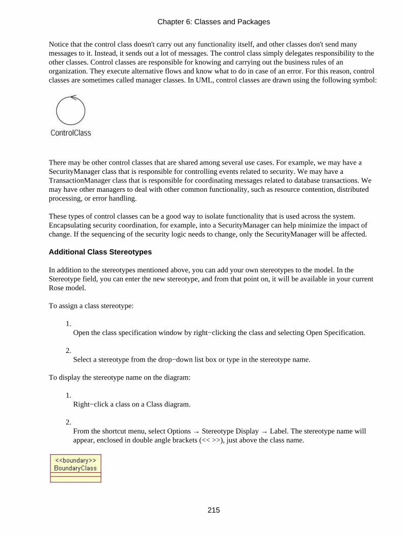
Notice that the control class doesn't carry out any functionality itself, and other classes don't send manymessages to it. Instead, it sends out a lot of messages. The control class simply delegates responsibility to theother classes. Control classes are responsible for knowing and carrying out the business rules of anorganization. They execute alternative flows and know what to do in case of an error. For this reason, controlclasses are sometimes called manager classes. In UML, control classes are drawn using the following symbol:
There may be other control classes that are shared among several use cases. For example, we may have aSecurityManager class that is responsible for controlling events related to security. We may have aTransactionManager class that is responsible for coordinating messages related to database transactions. Wemay have other managers to deal with other common functionality, such as resource contention, distributedprocessing, or error handling.
These types of control classes can be a good way to isolate functionality that is used across the system.Encapsulating security coordination, for example, into a SecurityManager can help minimize the impact ofchange. If the sequencing of the security logic needs to change, only the SecurityManager will be affected.
Additional Class Stereotypes
In addition to the stereotypes mentioned above, you can add your own stereotypes to the model. In theStereotype field, you can enter the new stereotype, and from that point on, it will be available in your currentRose model.
To assign a class stereotype:
1. Open the class specification window by right−clicking the class and selecting Open Specification.
2. Select a stereotype from the drop−down list box or type in the stereotype name.
To display the stereotype name on the diagram:
1. Right−click a class on a Class diagram.
2. From the shortcut menu, select Options → Stereotype Display → Label. The stereotype name willappear, enclosed in double angle brackets (<< >>), just above the class name.
Chapter 6: Classes and Packages
215

To display the Stereotype icon on the diagram:
1. Right−click a class on a Class diagram.
2. From the shortcut menu, select Options → Stereotype Display → Icon.
3. The representation of the class will change to the appropriate icon. This example shows the icon foran Interface class:
Note Not all of the stereotypes have icons. If there is no icon for a stereotype, only the stereotype name willappear on the diagram.
To turn off the stereotype display on the diagram:
1. Right−click a class on a Class diagram.
2. From the shortcut menu, select Options → Stereotype Display → None. The class will still have astereotype, visible in the class specification window, but the stereotype will not display on thediagram.
To change the default stereotype display option:
1. Select Tools → Options.
2. Select the Diagram tab.
3. In the Compartments area, as shown in Figure 6.8, select or deselect the Show Stereotypes check boxto control whether or not the stereotype will display.
Chapter 6: Classes and Packages
216

Figure 6.8: Changing the default stereotype display
4. In the Stereotype Display area, select the default display type (None, Label, Decoration, or Icon).
To add a new stereotype to the current Rose model:
1. Open the class specification window.
2. Type a new stereotype in the Stereotype field. The new stereotype will now be available in thedrop−down list box as you add more classes, but only in the current Rose model.
3. To add a new Stereotype icon for the new stereotype, see the online help ("Stereotype ConfigurationFile").
Class Types
In design, we want to categorize our classes using the terminology of the particular programming language weare going to use. For example, if we are using Visual Basic, we may have stereotypes such as Class Module,Collection, or Form. If we are using Java, we would need stereotypes for session objects, servlets, interfaces,and so on.
Rose supports a number of different stereotypes for its different language options. This section describes thetypes of classes that are available. In the following sections, we'll discuss stereotypes for several of thelanguages supported by Rational Rose.
Chapter 6: Classes and Packages
217

Parameterized Class
A parameterized class, the first of the special types of classes we'll discuss, is a class that is used to create afamily of other classes. Typically, a parameterized class is some sort of container; it is also known as atemplate. Not all languages directly support templates; you can use them in C++, Visual C++, or Ada.
For example, you may have a parameterized class called List. Using instances of the parameterized class, youcan create some classes called EmployeeList, OrderList, or AccountList, as described below.
In UML, a parameterized class is displayed using this notation:
To add a parameterized class:
1. Select the Parameterized Class button from the toolbar.
2. Click anywhere inside the diagram to place the new class.
3. Type the name of the class.
OR
1. Add a class to a Class diagram or to the browser using one of the methods listed above.
2. Open the class specification window.
3. In the Type field, select ParameterizedClass.
4. Press OK.
OR
1. Select Tools → Create → Parameterized Class.
2. Click anywhere inside the diagram to place the new class.
3.
Chapter 6: Classes and Packages
218

Type the name of the class.
Setting Arguments for a Parameterized Class
The arguments for the class are displayed in the dashed−line box. The arguments are placeholders for theitems that the parameterized class will contain. Using our example from the last section, we can replace theparameter item with a specific thing, such as Employee, to instantiate an EmployeeList class.
The argument can be another class, a data type, or a constant expression. You can add as many arguments asyou need.
To add an argument:
1. Open the class specification window by right−clicking the class and selecting Open Specification.
2. Select the Detail tab.
3. Right−click anywhere inside the white space in the Formal Arguments area.
4. Select Insert from the shortcut menu.
5. Type the argument name.
6. Click below the Type column header to display a drop−down list of argument types, as shown inFigure 6.9. Select one of the types in the list or enter your own.
Chapter 6: Classes and Packages
219

Figure 6.9: Adding an argument to a parameterized class
7. Click below the Default Value column header to enter a default value for the argument. A defaultvalue is not required.
To delete an argument:
1. Open the class specification window.
2. Select the Detail tab.
3. Right−click on the argument you wish to delete.
4. Select Delete from the shortcut menu.
Instantiated Class
An instantiated class is a parameterized class that has actual values for the arguments. From our last example,we know that we have a list of items. Now, we can supply a value for the Items argument, to see that we havea list of employees. UML notation for an instantiated class is a class with the argument name enclosed inangle brackets (< >):
Chapter 6: Classes and Packages
220

The number of actual values in an instantiated class must match the number of formal arguments in theparameterized class that it instantiates. If an argument is another class, then there should be a dependency onthat class.
To add an instantiated class:
1. Select the Instantiated Class button from the toolbar.
2. Click anywhere inside the diagram to place the new class.
3. Type the name of the class with the arguments in angle brackets (< >).
OR
1. Add a class to a Class diagram or to the browser using one of the methods listed above.
2. Open the class specification window.
3. In the Type field, select InstantiatedClass.
4. Click OK.
OR
1. Select Tools → Create → Instantiated Class.
2. Click anywhere inside the diagram to place the new class.
3. Type the name of the class.
Class Utility
A class utility is a collection of operations. For example, you may have some mathematicalfunctions—squareroot(), cuberoot(), and so on—that are used throughout your system but don't fit well intoany particular class. These functions can be gathered together and encapsulated into a class utility for use by
Chapter 6: Classes and Packages
221

the other classes in the system.
Utility classes are frequently used to extend the functionality provided by the programming language or tohold collections of generic, reusable pieces of functionality that are used in many systems.
A class utility will appear as a shadowed class on the diagram with this symbol:
To add a class utility:
1. Select the Class Utility button from the toolbar.
2. Click anywhere inside the diagram to place the new class.
3. Type the name of the class.
OR
1. Add a class to a Class diagram or to the browser using one of the methods listed above.
2. Open the class specification window.
3. In the Type field, select ClassUtility.
4. Press OK.
OR
1. Select Tools → Create → Class Utility.
2. Click anywhere inside the diagram to place the new class.
3. Type the name of the class.
Chapter 6: Classes and Packages
222

Parameterized Class Utility
A parameterized class utility is a parameterized class that contains a set of operations. It is the template that isused to create class utilities. It appears on a Class diagram with the following symbol:
To add a parameterized class utility:
1. Select the Parameterized Class Utility button from the toolbar.
2. Click anywhere inside the diagram to place the new class.
3. Type the name of the class.
OR
1. Add a class to a Class diagram or to the browser using one of the methods listed above.
2. Open the class specification window.
3. In the Type field, select ParameterizedClassUtility.
4. Press OK.
OR
1. Select Tools → Create → Parameterized Class Utility.
2. Click anywhere inside the diagram to place the new class.
3. Type the name of the class.
Instantiated Class Utility
An instantiated class utility is a parameterized class utility that has values set for the parameters. It appears ona Class diagram as follows:
Chapter 6: Classes and Packages
223

To add an instantiated class utility:
1. Select the Instantiated Class Utility button from the toolbar.
2. Click anywhere inside the diagram to place the new class.
3. Type the name of the class.
OR
1. Add a class to a Class diagram or to the browser using one of the methods listed above.
2. Open the class specification window.
3. In the Type field, select InstantiatedClassUtility.
4. Click OK.
OR
1. Select Tools → Create → Instantiated Class Utility.
2. Click anywhere inside the diagram to place the new class.
3. Type the name of the class.
Interfaces
One guideline in object−oriented programming is to separate the implementation of a class from its interface.Most object−oriented languages now support the concept of an interface, which contains only the methodsignatures (without the implementation) for a class.
For example, we may have a class that deals with security. It has methods called CheckID, CheckPassword,and LogSecurityViolation. The CheckID operation takes the user ID as a parameter and returns a Booleansignifying whether or not the ID is valid. CheckPassword takes the password entered by the user and alsoreturns a Boolean. LogSecurityViolation takes no parameters.
Chapter 6: Classes and Packages
224

Various pieces of the system will need to call the CheckID operation, for example. The typical approach is tocreate a class, which we'll call SecurityImplementer, that contains all three of the security methods as well ascode to implement the functions.
One option is to allow the rest of the system to directly call methods of the SecurityImplementer classwhenever they need security functionality. A problem could occur, however, if the Security−Implementerclass changes. What happens if we change the way that the methods work or if we want to replace ourC++−based security class with a Java−based security class? There could be ripple effects throughout thesystem.
So rather than take this approach, we create the SecurityImplementer class with its methods and theirimplementations, but we also create a SecurityInterface class, which holds only the operation signatures.Other classes will reference the interface rather than the implementer class so that if the implementer needs tochange, the rest of the system won't be affected.
This concept has been used as the basis for interface definition language (IDL), which allows you to definelanguage−independent interfaces. In Rose, an interface is modeled as a class with a circle icon, which is oftencalled a "lollipop," as follows:
Web Modeling Stereotypes
One of the new features in Rose is the support of web modeling stereotypes. Using this feature, you can morethoroughly describe the structure of your web applications, labeling which classes in the model correspond toclient pages, server pages, applets, session objects, or other web constructs.
Note You can read more about this topic in Chapter 19, "Web Modeling."In this section, we'll briefly discuss each of the stereotypes available in Rose Web Modeler. If you are usingthese stereotypes, you may first want to customize the Class Diagram toolbar to be able to see buttons forthese. To do so, open a Class diagram and right−click the Class Diagram toolbar. Select Customize, find theweb stereotype buttons, and then add them to the toolbar.
Many of these stereotypes have their own symbols on a Class diagram. In Rose, you can view the classes withtheir symbols by right−clicking the class and selecting Options → Stereotype Display → Icon. To switch backto stereotypes with text labels instead, select the Label option.
Note If you have changed the stereotype display to Icon but you're still not seeing the symbols, be sure thedefault language on the Notation tab of Tools → Options is set to Web Modeler before you create theclasses. If the classes are already created, be sure they are mapped to a component whose language isset to Web Modeler (see Chapter 10, "Component View," for component mapping).
Client Page
A client page is an HTML−formatted page that is displayed on the client machine by a web browser. A clientpage may have some embedded logic with JavaScript or VBScript, but typically will carry out only userinterface logic. In most situations, business logic should, whenever possible, be carried out on the server.
In Rose, a client page is modeled with the following symbol:
Chapter 6: Classes and Packages
225

Server Page
A server page is a page that is executed on the server and typically carries out business, rather than userinterface, functionality. The server page can communicate with the resources available on the server, such asthe database, other server pages, and business objects. The separation between client and server pages helpsthe team to separate the business logic from the user interface.
In Rose, a server page is modeled with the following symbol:
Form
A form is a simple HTML page that doesn't do business processing. It exists only to display information to theend user and to allow the end user to enter some information in simple fields. Once the user enters theinformation, the form passes control to a server page, which carries out any business logic in response to theinformation on the form.
On a Class diagram, a form looks like this:
Application
One of the challenges in web programming is the inability to keep track of the client's state. In other words,once a client has made a request to the server and the server has processed the request, the server does notkeep track of where the client is or what it is doing. If the client needs something else, it needs to establish anew connection to the server and send a new request.
When using Active Server Pages (ASP), an application object helps with this problem. It allows the server tokeep track of some information across all of the clients that are currently using the system. All clients share
Chapter 6: Classes and Packages
226

the same application object.
In Rose, an application object is modeled as a class with a Web Application stereotype:
Applet
An applet is a Java construct. It is a (typically small) compiled program that is downloaded to the client andruns on the client machine. Applets are frequently used to add some functionality to the user interface that isnot generally available. Although ActiveX controls serve the same purpose, they are not currently supportedby all browsers.
Applets are shown on a Class diagram with the following symbol:
Session
Session objects exist for largely the same reason as application objects. The difference is that while all clientsshare the same application object, a session object is unique to a particular client. It allows the server to keeptrack of what the client is doing and what it has requested in the past—in other words, the state of the client.
A session object is modeled as a class with a Web Session stereotype:
COM Object
The COM object stereotype is used to model ActiveX components. Although not all browsers currentlysupport ActiveX, there are a number of ActiveX controls in use today (and more are being created all thetime!). As long as you know that your clients are running Microsoft's Internet Explorer or another browserthat supports ActiveX, you can use these controls to enhance the user interface. Like applets, ActiveX controlsrun on the client machine.
COM objects appear on the Class diagram with the following symbol:
Chapter 6: Classes and Packages
227

Other Language Stereotypes
In addition to the stereotypes discussed above, Rose supports different stereotypes for Visual Basic, Java,XML, CORBA, COM, and other types of classes. Table 6.2 lists the stereotypes for the different languagesavailable in Rose.
Table 6.2: Language−Specific Stereotypes in Rose
Language Stereotypes
Visual Basic Add−InDesigner
ADO Class
Class Module
Collection
Custom Webitem
Data Environment
Data Report
DHTML Page
Enum
Form
MDI Form
Module
MTS Class
Property Page
Template Webitem
Type
User Control
Chapter 6: Classes and Packages
228

User Document
User Connection
Web Class
Java EJB Entity
EJB Home Interface
EJBPrimaryKey
EJBRemoteInterface
EJBSession
Generic Servlet
HTTP Servlet
CORBA Constant
Enumeration
Exception
Struct
Typedef
Union
Value
Custom Value
COM Alias
Coclass
Enum
Module
Struct
Union
Oracle 8 Nested Table
Object Table
Object Type
Chapter 6: Classes and Packages
229

Object View
Relational Table
Relational View
VARRAY
XML DTD Element
DTD Entity
DTD Sequence Group
DTD Notation
Class Specifications
Most of the options that you can set for a class are available on the class specification window, as shown inFigure 6.10. For example, this window allows you to set the class stereotype, visibility, and persistence. In thefollowing sections, we'll talk about each of the options available on the tabs of this window.
Figure 6.10: Class specification window
If you are examining the specifications for a Java, XML, or CORBA class, the specification window thatappears is slightly different, as shown below in Figure 6.11. All of the options on this window are alsoavailable through the standard specification window.
Chapter 6: Classes and Packages
230

Figure 6.11: Java specification window
To open the class specifications:
1. Right−click the class on a Class diagram.
2. Select Open Specification from the shortcut menu.
OR
1. Right−click the class in the browser.
2. Select Open Specification from the shortcut menu.
OR
1. Select the class on a Class diagram.
2. Select Browse → Specification, or press Ctrl+B.
Naming a Class
Each class in your Rose model should be given a unique name. Most organizations have a naming conventionto follow when naming a class. In general, however, classes are named using a singular noun. In our airlinereservation system, for example, we may have a class called Flight and another called Airplane. (We wouldnot call them flights and airplanes.)
Chapter 6: Classes and Packages
231

Class names typically do not include spaces. This is for practical reasons as well as readability—manyprogramming languages do not support spaces in class names. Try to keep your class names relatively short.While ListOfEmployeesThatAreOnProbation is a very good description of what that class does, it can makethe code rather unreadable. EmployeeList might be a better class name in this case.
Whether to use uppercase or lowercase letters really depends on your organization. If we have a class that is alist of employees, it could be called employeelist, Employeelist, EmployeeList, or EMPLOYEELIST. Again,each company typically has a naming convention. Just be sure that whichever approach is decided upon isused for all classes.
To name a class:
1. Select the class in the browser or on the Class diagram.
2. Type the class name.
OR
1. Open the class specification window.
2. In the Name field, enter the class name.
To add documentation to a class:
1. Select the class in the browser.
2. In the documentation window, type the class documentation.
OR
1. Open the class specification window.
2. In the specification window, type the information in the Documentation area.
Setting Class Visibility
The Visibility option determines whether or not a class can be seen outside of its package. It is controlledthrough the Export Control field in the specification window. There are three visibility options for a class:
Public Suggests that the class can be seen by all of the other classes in the system.
Protected or Private Suggests that the class can be seen in nested classes, friends, or within the same class.
Chapter 6: Classes and Packages
232

Package or Implementation Suggests that the class can be seen only by other classes in the same package.
To set class visibility:
1. Right−click the class in the browser or on a Class diagram.
2. Select Open Specification from the shortcut menu.
3. Set the export control to Public, Protected, Private, or Implementation.
If a class has protected, private, or package visibility, it cannot be seen by classes in other packages. Anaccess violation occurs in one of two situations:
• When there is a relationship between two classes in different packages, but there is no dependencyrelationship between the packages themselves
• When there is a relationship between classes in different packages, and the supplier class hasimplementation visibility
In Rose, open a Class diagram and select Report → Show Access Violations to check for one of these twoproblems.
Setting Class Multiplicity
The Multiplicity field gives you a place to set the number of instances that you expect to have of a class. Inthe employee tracking system, we can probably expect to have many instances of the Employee class—onefor John Doe, one for Fred Smith, and so on. The multiplicity for the Employee class, then, would be n.Control classes, however, frequently have a multiplicity of 1. As you're running the application, you probablyneed only one instance of a security manager.
In Rose, the following multiplicity options are available in the drop−down list box:
Multiplicity Meaning
n (default) Many
0..0 Zero
0..1 Zero or one
0..n Zero or more
1..1 Exactly one
1..n One or moreOr you can enter your own multiplicity, using one of the following formats:
Format Meaning
<number> Exactly <number>
Chapter 6: Classes and Packages
233

<number 1>..<number 2> Between <number 1> and <number 2>
<number>..n <number> or more
<number 1>,<number 2> <number 1> or <number 2>
<number 1> , <number 2> .. <number 3> Exactly <number 1> or between <number 2> and<number 3>
<number 1> .. <number 2> , <number 3> .. <number4>
Between <number 1> and <number 2> or between<number 3> and <number 4>
To set class multiplicity:
1. Open the class specification window.
2. Select the Detail tab.
3. From the Multiplicity drop−down list box, select the multiplicity. Or type in a multiplicity option thatis not available in the drop−down list box.
Setting Storage Requirements for a Class
As you are building your model, you may want to note the amount of relative or absolute memory you expecteach object of the class to require. The Space field in the class specification window is used for this purpose.
You cannot use the Space field for class utilities, instantiated class utilities, or parameterized class utilities.
To set class space:
1. Open the class specification window.
2. Select the Detail tab.
3. Enter the storage requirements for the class in the Space field.
Setting Class Persistence
In Rose, you can generate DDL (data definition language) from your model. The DDL defines the structure ofyour database.
When you generate DDL, Rose will look for classes that have been set to Persistent. The Persistence field inthe class specification window is used to specify whether a class is Persistent or Transient:
Persistent Suggests that the class will live beyond the execution of the application. In other words, theinformation in objects of the class will be saved to a database or some other form of persistent storage.
Transient Suggests that information in objects of the class will not be saved to persistent storage.
Chapter 6: Classes and Packages
234

You cannot use the Persistence field for class utilities, instantiated class utilities, or parameterized classutilities.
To set the persistence of a class:
1. Open the class specification window.
2. Select the Detail tab.
3. Select Persistent or Transient in the Persistence area.
Setting Class Concurrency
Concurrency is used to describe how the class behaves in the presence of multiple threads of control. Thereare four concurrency options:
Sequential This is the default setting, and suggests that the class will behave normally (i.e., the operationswill perform as expected) when there is only one thread of control, but the behavior of the class is notguaranteed in the presence of multiple threads of control.
Guarded Suggests that the class will behave as expected when there are multiple threads of control, but theclasses in the different threads will need to collaborate with each other to ensure that they don't interfere witheach other.
Active Suggests that the class will have its own thread of control.
Synchronous Suggests that the class will behave as expected, with multiple threads of control. There won'tbe any collaboration required with other classes, because the class will deal with the mutual exclusion on itsown.
To set the concurrency of a class:
1. Open the class specification window.
2. Select the Detail tab.
3. Select a concurrency radio button in the Concurrency area.
Creating an Abstract Class
An abstract class is a class that will not be instantiated. In other words, if Class A is abstract, there will neverbe any objects of Type A in memory. A class is defined as being abstract if at least one operation of the classis abstract. Rose does not enforce this rule.
Chapter 6: Classes and Packages
235
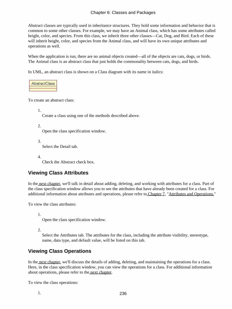
Abstract classes are typically used in inheritance structures. They hold some information and behavior that iscommon to some other classes. For example, we may have an Animal class, which has some attributes calledheight, color, and species. From this class, we inherit three other classes—Cat, Dog, and Bird. Each of thesewill inherit height, color, and species from the Animal class, and will have its own unique attributes andoperations as well.
When the application is run, there are no animal objects created—all of the objects are cats, dogs, or birds.The Animal class is an abstract class that just holds the commonality between cats, dogs, and birds.
In UML, an abstract class is shown on a Class diagram with its name in italics:
To create an abstract class:
1. Create a class using one of the methods described above.
2. Open the class specification window.
3. Select the Detail tab.
4. Check the Abstract check box.
Viewing Class Attributes
In the next chapter, we'll talk in detail about adding, deleting, and working with attributes for a class. Part ofthe class specification window allows you to see the attributes that have already been created for a class. Foradditional information about attributes and operations, please refer to Chapter 7, "Attributes and Operations."
To view the class attributes:
1. Open the class specification window.
2. Select the Attributes tab. The attributes for the class, including the attribute visibility, stereotype,name, data type, and default value, will be listed on this tab.
Viewing Class Operations
In the next chapter, we'll discuss the details of adding, deleting, and maintaining the operations for a class.Here, in the class specification window, you can view the operations for a class. For additional informationabout operations, please refer to the next chapter.
To view the class operations:
1.
Chapter 6: Classes and Packages
236

Open the class specification window.
2. Select the Operations tab. The operations for the class, including the operation visibility, stereotype,signature, and return type, will be listed on this tab.
Viewing Class Relationships
In Chapter 8, we will discuss in detail the different types of relationships you can add to classes. We'll talkabout adding and deleting relationships and setting the detailed information about each relationship. In theclass specification window, you can view all of the relationships that have been added to a class. Foradditional information about relationships between classes, please refer to Chapter 8.
To view the class relationships:
1. Open the class specification window.
2. Select the Relations tab. All of the relationships in which the class participates will be listed on thistab.
Using Nested Classes
In Rose, you can nest one class inside another. You can also nest additional classes inside the nested class, toas many levels of depth as necessary.
To create a nested class:
1. Open the class specification window for the parent class.
2. Select the Nested tab.
3. Right−click anywhere inside the white space on the Nested tab.
4. Select Insert from the shortcut menu.
5. Type the name of the nested class.
OR
1. Create and name the parent class.
2.
Chapter 6: Classes and Packages
237
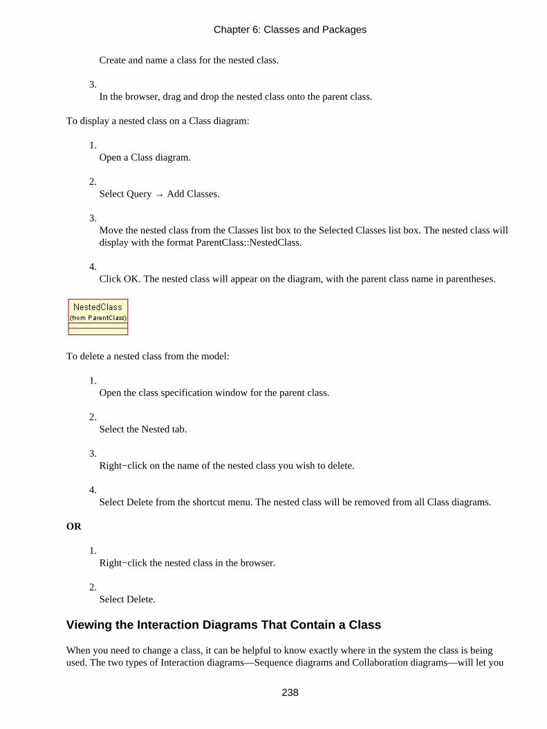
Create and name a class for the nested class.
3. In the browser, drag and drop the nested class onto the parent class.
To display a nested class on a Class diagram:
1. Open a Class diagram.
2. Select Query → Add Classes.
3. Move the nested class from the Classes list box to the Selected Classes list box. The nested class willdisplay with the format ParentClass::NestedClass.
4. Click OK. The nested class will appear on the diagram, with the parent class name in parentheses.
To delete a nested class from the model:
1. Open the class specification window for the parent class.
2. Select the Nested tab.
3. Right−click on the name of the nested class you wish to delete.
4. Select Delete from the shortcut menu. The nested class will be removed from all Class diagrams.
OR
1. Right−click the nested class in the browser.
2. Select Delete.
Viewing the Interaction Diagrams That Contain a Class
When you need to change a class, it can be helpful to know exactly where in the system the class is beingused. The two types of Interaction diagrams—Sequence diagrams and Collaboration diagrams—will let you
Chapter 6: Classes and Packages
238

know exactly where and how each class is being used. You can use the Report menu to see which Sequenceand Collaboration diagrams contain objects of a particular class.
To view all Sequence and Collaboration diagrams that contain a certain class:
1. Select the class on a Class diagram.
2. Select Report → Show Instances.
3. Rose will display a list of all Sequence and Collaboration diagrams that contain objects of that class,as shown in Figure 6.12. To open a diagram, double−click it in the list, or click the Browse button.
Figure 6.12: Viewing class instances
Setting Java Class Specifications
In Rose, Java classes have two specification windows: the standard specification, as described above, and aJava specification window. The Java specification window is used to set Java−specific fields, such as whetherto generate a default constructor. Figure 6.13 shows the Java Class Specification window.
Figure 6.13: Java Class Specification window
Using this window, you can set the following:
•
Chapter 6: Classes and Packages
239

Name is equivalent to setting the name on the standard specification window.
• Visibility controls whether the class is public and can be seen by all classes, or is visible only toclasses in the same package. Possible values are Public or Package. Setting the value to Package isequivalent to setting the Export Control to Implementation in the standard specification window.
• Abstract sets the class to be abstract, which implies that the class will never be directly instantiated.Setting this flag on the Java specification window is equivalent to checking the Abstract check box onthe Detail tab of the standard specification window.
• Final determines whether subclasses of the class may be created. If the Final flag is set to True,subclasses may not be created.
• Generate is a set of four flags that determine whether to generate a finalize method, static initializer,instance initializer, and/or default constructor when generating code.
• Interface sets whether this class is an interface. Checking this box is equivalent to setting the classstereotype to Interface in the standard specification window.
• Generate Code controls whether Rose will generate code for this class. By default, this option isselected.
• Disable Autosync will disable autosync for this class. Autosync is a feature that will automaticallyinitiate the code−generation process when a Java element is modified. To enable or disable autosyncfor the entire model, select Tools → Java → Project Specification and then the Detail tab. At thebottom of the screen is an option for autosynchronization.
• Constructor Visibility sets the visibility of the class's constructor to Public, Package, Private, orProtected.
• Extends indicates whether the class is a subclass of another. If so, the parent class is listed.
• Implements indicates whether the class implements the functionality listed in an interface. If so, theinterface is listed.
• DocComment provides comments for the class. This is equivalent to typing comments in theDocumentation field of the standard specification window.
Chapter 6: Classes and Packages
240

Setting CORBA Class Specifications
As with Java, CORBA classes have their own specification window. You can use this window to setCORBA−specific information, such as enumeration attribute ordering or constant types and values. Thespecification window will vary slightly, depending upon the stereotype of the CORBA class you are workingwith. An example of the CORBA specification window is shown in Figure 6.14.
Figure 6.14: CORBA Class Specifications
Using the CORBA specification window, you can set the following information. Note that some of theseoptions are available only for certain CORBA stereotypes.
• Name sets the name of the class. This is equivalent to setting the name on the standard specificationwindow.
• Stereotype displays the stereotype of the class. To change the stereotype, open the standardspecification window.
• Implementation Type (Constant, Typedef) sets the data type of the constant or typedef.
• Constant Value (Constant) sets the value of the constant.
• Array Dimensions (Typedef) sets the dimensions of the typedef's declarator.
• Attribute/Role Ordering (Enumeration, Union, Exception, Struct, Value, Custom Value) is used toset the order of the attributes in the class. When code is generated, the attributes will be generated inthis order.
• Inherits From (Value, Custom Value) sets the parent class, if the class is inherited.
•
Chapter 6: Classes and Packages
241

Switch Type (Union) is the variable used for the case statements generated for the class.
Working with Packages
A package is used to group together classes that have some commonality. In UML, a package is displayedwith this symbol:
There are a few common approaches when packaging classes, but you can group the classes together howeveryou'd like. One approach is to group the classes together by stereotype. With this approach, you have onepackage with your client page classes, one with your server page classes, one with your applets, and so on.This can be a helpful approach to take for deployment's sake—all the forms that will go on the client machineare already packaged together.
Another approach is to group the classes together by functionality. For example, you might have a packagecalled Security, which holds all of the classes that deal with application security. You might have some otherpackages called Employee Maintenance, Reporting, or Error Handling. The advantage of this approach is inreuse. If you carefully group your classes together, you end up with packages that are fairly independent ofone another. In this example, you can just pick up the Security package and reuse it in other applications.
Finally, you can use a combination of these approaches. Packages can be nested inside each other to furtherorganize your classes. At a high level, you may group your classes by functionality to create your Securitypackage. Within this package, you can have some other packages, grouping the security classes byfunctionality or stereotype.
Adding Packages
The next step in creating your model is adding some packages. Class packages are created in the Logical viewof the browser.
To add an existing package to a Class diagram:
Drag the package from the browser onto the Class diagram.
To add a new package to a Class diagram:
1. Select the Package toolbar button.
2. Click anywhere inside the Class diagram to place the package.
3.
Chapter 6: Classes and Packages
242

Type the package name.
To add a package to the browser:
1. Right−click Logical View in the browser. To create a package inside an existing package, right−clickthe existing package in the browser.
2. Select New → Package.
3. Type the name of the new package.
To move an item into a package:
In the browser, drag the item from its existing location to the new package.
Deleting Packages
You can delete a package from a Class diagram or from the entire model. If you delete a package from themodel, the package and all of its contents will be removed.
To remove a package from a Class diagram:
1. Select the package on the Class diagram.
2. Press the Delete key.
Note that the package has been removed from the Class diagram, but still exists in the browser and on otherClass diagrams.
To remove a package from the model:
1. Right−click the package in the browser.
2. Select Delete from the shortcut menu.
OR
1. Select the package on a Class diagram.
2. Select Edit → Delete from Model, or press Ctrl+D.
Warning
Chapter 6: Classes and Packages
243

When you delete a package from the model, all classes and diagrams within the package will alsobe deleted.
Exercise
In this exercise, we'll take the classes we created last time and group them into packages. Then we'll createsome Class diagrams to show the classes in the system and the packages.
Problem Statement
From the Interaction diagrams, Andy could see that the system met the business needs of the company. So hespoke with Karen, the lead developer.
• "Here are the Interaction diagrams for adding a new order."
• "Great! I'll get going on development."
Karen took a look at the classes in the Rose model. She decided to group them together by stereotype. So, shecreated packages called Entities, Boundaries, and Control, and moved each class into the appropriate package.Then, she created a Class diagram in each package: a Main Class diagram to display the packages and anEnter New Order Class diagram to show all of the classes for that use case.
Creating a Class Diagram
Group the classes that we've identified so far into packages. Create a Class diagram to display the packages,Class diagrams to display the classes in each package, and a Class diagram to display all of the classes in the"Enter New Order" use case.
Exercise Steps:
Setup
1. Select Tools → Options.
2. Select the Diagram tab.
3. Be sure the Show Stereotypes check box is selected.
4. Be sure the Show All Attributes and Show All Operations check boxes are selected.
5. Be sure the Suppress Attributes and Suppress Operations check boxes are not checked.
Create Packages
1.
Chapter 6: Classes and Packages
244

Right−click Logical View in the browser.
2. Select New → Package.
3. Name the new package Entities.
4. Repeat steps 1–3 to create a Boundaries package and a Control package.
At this point, the browser should look like Figure 6.15.
Figure 6.15: Packages for the shopping cart system
Create Main Class Diagram
1. Double−click the Main Class diagram, directly underneath the Logical View in the browser, to openthe diagram.
2. Drag the Entities package from the browser to the diagram.
3. Drag the Boundaries and Control packages from the browser to the diagram.
The Main Class diagram should look like Figure 6.16.
Chapter 6: Classes and Packages
245

Figure 6.16: Main Class diagram for the shopping cart system
Create Class Diagram with All Classes in the "Add Item to Shopping Cart" Use Case
1. Right−click Logical View in the browser.
2. Select New → Class Diagram.
3. Name the new Class diagram Add Item to Shopping Cart.
4. Double−click the Add Item to Shopping Cart Class diagram in the browser to open it.
5. Select the Class toolbar button and add the following classes to the diagram: CartMgr, CartInterface,ProductMgr, Product, ProductCollection, CartCollection, and CartItem.
The Class diagram should look like Figure 6.17.
Figure 6.17: Add Item to Shopping Cart Class Diagram
Add Stereotypes to the Classes
1. Right−click the CartInterface class in the diagram.
2.
Chapter 6: Classes and Packages
246

Select Open Specification from the shortcut menu.
3. In the stereotype field, type Boundary.
4. Click OK.
5. Right−click the CartMgr class in the diagram.
6. Select Open Specification from the shortcut menu.
7. In the stereotype field, type Control.
8. Click OK.
9. Repeat steps 1–4 to assign the CartCollection, Product, ProductCollection, and CartItem classes theentity stereotype.
The Class diagram should look like Figure 6.18.
Figure 6.18: Stereotypes for classes in Add Item to Shopping Cart use case
Group Classes into Packages
1. In the browser, drag the CartInterface class to the Boundaries package.
2. Drag the CartMgr and ProductMgr classes to the Control package.
3.
Chapter 6: Classes and Packages
247

Drag the CartCollection, Product, ProductCollection, and CartItem classes to the Entities package.
The classes and packages in the browser are shown in Figure 6.19.
Figure 6.19: Classes and packages in the Add Item to Shopping Cart use case
Add Class Diagrams to Each Package
1. In the browser, right−click the Boundaries package.
2. Select New → Class Diagram.
3. Name the new diagram Main.
4. Double−click the new diagram to open it.
5. Drag the CartInterface class from the browser to the diagram.
The Main Class diagram for the Boundaries package should look like Figure 6.20.
Chapter 6: Classes and Packages
248

Figure 6.20: Main Class diagram for Boundaries package
6. Close the diagram.
7. Right−click the Entities package in the browser.
8. Select New → Class Diagram.
9. Name the new diagram Main.
10. Double−click the new diagram to open it.
11. Drag the CartCollection, Product, ProductCollection, and CartItem classes from the browser to thediagram.
The Main Class diagram for the Entities package should look like Figure 6.21.
Figure 6.21: Main Class diagram for Entities package
12. Close the diagram.
13. Right−click the Control package in the browser.
14.
Chapter 6: Classes and Packages
249

Select New → Class Diagram.
15. Name the new diagram Main.
16. Double−click the new diagram to open it.
17. Drag the CartMgr and ProductMgr classes from the browser to the diagram.
18. Close the diagram.
The Main Class diagram for the Control package should look like Figure 6.22.
Figure 6.22: Main Class diagram for Control package
Summary
In this chapter, we discussed classes, Class diagrams, and packages. By now, we have greatly improved ourview of the system that is being built. By the end of the last chapter, we had created Object Interactiondiagrams such as Collaboration diagrams and Sequence diagrams. These illustrate the interactions required forthe system to perform its functions. In this chapter, we created Class diagrams to show the static behavior inthe system. We also organized the classes into packages in order to better understand the system. Next, wewill look in detail at the attributes and operations of the classes.
Chapter 6: Classes and Packages
250

Chapter 7: Attributes and OperationsIn the previous chapter, we looked at classes and packages. Remember that classes are encapsulated attributes(data) and the operations (behaviors) that act on those attributes. Now we will discuss working with attributesand operations. We will begin by talking about how to find attributes, add them to the Rose model, and adddetails about the attributes. We will then look at finding operations, adding them to the model, and addingdetails to the operations. Next, we will look at displaying attributes and operations on Class diagrams. Lastly,we will discuss how to map operations to messages on Interaction diagrams.
Working with Attributes
An attribute is a piece of information associated with a class. For example, a Company class might haveattributes called Name, Address, and NumberOfEmployees. A Ticket class might have attributes calledFlightNumber, Cost, and PassengerName.
In Rose, you may add one or more attributes to each of the classes in the model. The following sectionsdescribe how to find attributes, add them to the model, delete them from the model, and set the detailedspecifications for each attribute.
Finding Attributes
There are many sources of attributes. To begin, you can take your use case documentation and look for nounsin your flow of events. Some of the nouns will be objects or classes, some will be actors, and others will beattributes. For example, your flow of events may read "The user enters the employee's name, address, socialsecurity number, and phone number," letting you know that the Employee class has attributes called Name,Address, SSN, and Phone. In our airline example, the user is looking for a flight and enters a departure anddestination city as well as a departure date. From this, we know that a Flight class would have attributes calledDepartureCity, DestinationCity, and DepartureDate.
Another good place to look is the requirements document. There may be requirements that outline whatinformation should be collected by the system. Any piece of information that is collected should be anattribute in a class.
Finally, you can check the database structure. If your database structure has already been defined, the fields inthe tables will give you a good idea of what your attributes are. Frequently, there's a one−to−one mappingbetween database tables and entity classes. Going back to our previous example, a Flight table may havefields called DepartureCity, DestinationCity, and DepartureDate. The corresponding class, called Flight, willhave attributes called DepartureCity, DestinationCity, and DepartureDate. It's important to note that there isn'talways a one−to−one mapping between the database tables and the classes. There are different considerationswhen designing your database and designing your classes. Relational databases, for example, don't directlysupport inheritance.
However, when you identify attributes, be sure that each one can be traced back to a requirement. This canhelp solve the classic problem of an application capturing a great deal of information that nobody uses. Eachrequirement should be traced back to the flow of events of a use case, to a particular requirement, or to anexisting database table. If you cannot trace the requirement, you cannot be sure that it is needed by thecustomer. This can be a bit of a deviation from some older methodologies—rather than create the databasestructure first and then wrap the system around it, you're building the system and the database at the sametime to conform to the same requirements.
251
As you identify attributes, carefully assign them to the appropriate classes. An attribute should be a piece ofinformation related to the class. For example, an Employee class might have name and address information,but shouldn't include information about the products the employee's company manufactures. A Product classwould be a better place to store information about products.
Be cautious of classes with too many attributes. If you find that a particular class has a large number ofattributes, it might be an indication that the class should be split into two smaller classes. If you have a classwith more than about 10 or 15 attributes, be sure to take a close look at it. The class may be perfectlylegitimate; just be sure that all of the attributes are needed and truly belong to that class. Similarly, be cautiousof classes with too few attributes. Again, it may be perfectly legitimate. Control classes, for example, tend tohave very few attributes. However, it may also be a sign that two or more classes should be combined. If youhave a class with only one or two attributes, it may be worth a closer look.
Sometimes you may run into a piece of information and wonder whether it's an attribute or a class. Forexample, let's look at an attribute like Company Name. The question you face might be: Is the company namean attribute of a Person class, or should Company be its own class? The answer really depends on theapplication you are writing. If you need to keep information about the company and there is some behaviorassociated with a company, it may be its own class. For example, you may be building a system to keep trackof your customers. In this case, you'll want to keep some information about the companies you sell productsor services to. You may want to know how many employees the company has, the company's name andaddress, the name of your contact with the company, and so on.
On the other hand, you may not need to know specific information about the company. You may be writing anapplication that will generate letters to your contacts in other organizations. When generating the letters, youwill need to know a company name. However, you don't need to know any more information about thecompany. In this case, you could consider the company name to be an attribute of a Contact class.
Another thing to consider is whether the piece of information in question has behavior. If the Company hassome behavior in your application, it is better modeled as a class. If the company has no behavior, it may bebetter modeled as an attribute.
Once you've identified the attributes, the next step is to add them to your Rose model. In the followingsections, we'll discuss how to add attributes and add details to the attributes, such as the data type and defaultvalue.
Adding Attributes
As you identify attributes, you can add them to the appropriate class in your Rose model. There are three mainpieces of information you can supply for each attribute: the attribute name, the data type, and the initial value.Before you can generate code for your model, you must supply a name and data type for each attribute. Initialvalues are optional.
There are three ways to add an attribute. You may type the attribute directly onto a Class diagram, add theattribute using the browser, or add the attribute using the class specification window.
Once you've added an attribute, you can add documentation for it. Typically, attribute documentation wouldinclude a short description or definition of the attribute. Any attribute documentation will be included as acomment in the code generated from the model. By documenting the attributes as you go along, you arebeginning to document the code as well.
To add an attribute to a class:
1.
Chapter 7: Attributes and Operations
252

Right−click the class on a Class diagram.
2. Select New → Attribute.
3. Type the attribute name, using the format Name : Data Type = Initial Value. For example:
Address : String
IDNumber : Integer = 0
The data type is required in order to generate code, but the initial value is optional.
4. To add more attributes, press Enter and type the new attributes directly on the Class diagram.
OR
1. Right−click the class in the browser.
2. Select New → Attribute.
3. A new attribute, called "name" by default, will appear under the class in the browser. Type the nameof the new attribute. Attribute data types and default values cannot be assigned in the browser; youcan enter them on the Class diagram, as we'll discuss shortly.
OR
1. Open the class specification window for the attribute's class.
2. Select the Attributes tab. If the class already has some attributes, they will be listed here.
3. Right−click anywhere inside the Attributes area, as in Figure 7.1.
Chapter 7: Attributes and Operations
253
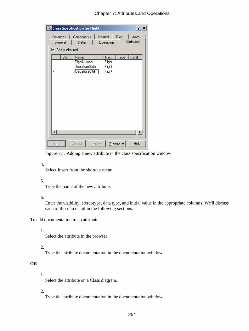
Figure 7.1: Adding a new attribute in the class specification window
4. Select Insert from the shortcut menu.
5. Type the name of the new attribute.
6. Enter the visibility, stereotype, data type, and initial value in the appropriate columns. We'll discusseach of these in detail in the following sections.
To add documentation to an attribute:
1. Select the attribute in the browser.
2. Type the attribute documentation in the documentation window.
OR
1. Select the attribute on a Class diagram.
2. Type the attribute documentation in the documentation window.
Chapter 7: Attributes and Operations
254

OR
1. Right−click the attribute in the browser.
2. Select Open Specification from the shortcut menu.
3. Enter the attribute documentation in the Documentation area of the class attribute specificationwindow.
OR
1. Open the class specification window for the attribute's class.
2. Select the Attributes tab.
3. Select the attribute.
4. Type the attribute documentation in the documentation window.
Deleting Attributes
At times, you may find that you need to delete an attribute you have created. This is most common when thesystem requirements change, removing the need for a particular attribute. In Rose, the quickest way to deletean attribute is typically through the browser. However, you can also use a Class diagram to delete an attribute.When an attribute is deleted from one Class diagram, Rose will automatically remove it from the model,including any other Class diagrams on which it appeared.
To delete an attribute from a class:
1. Right−click the attribute in the browser.
2. Select Delete from the shortcut menu.
OR
1. Select the attribute on a Class diagram.
2. Use the Backspace key to erase the attribute name, data type, and initial value from the diagram.
3.
Chapter 7: Attributes and Operations
255

Single−click anywhere on the diagram.
4. Rose will confirm the deletion before the attribute is removed.
OR
1. Open the class specification window for the attribute's class.
2. Select the Attributes tab.
3. Right−click the attribute you want to delete.
4. Select Delete from the shortcut menu.
5. Rose will confirm the deletion before the attribute is removed.
Setting Attribute Specifications
As with other Rose model elements, there are a number of detailed specifications you can add to an attribute.These include, among other things, the attribute data type, initial value, stereotype, and visibility. In the nextseveral sections, we'll take a look at each specification.
All of the specifications are viewed or changed on the attribute specification window, as shown in Figure 7.2.
Chapter 7: Attributes and Operations
256

Figure 7.2: Attribute specification window
To open the attribute specifications:
1. Right−click the attribute in the browser.
2. Select Open Specification from the shortcut menu.
OR
1. Open the class specification window for the attribute's class.
2. Select the Attributes tab.
3. Double−click the appropriate attribute.
Note In the following sections, if you are working with a Java, COM, or CORBA class, the specificationwindow will be different. To open the standard specifications, right−click and select Open StandardSpecification from the shortcut menu.
Setting the Attribute Data Type
One of the main pieces of information you specify about an attribute is its data type. The data type is thelanguage−specific type, such as string, integer, long, or Boolean. Before you can generate code, you mustenter a data type for each attribute.
Chapter 7: Attributes and Operations
257

When you are entering the data type, you can either use built−in data types (string, integer, long, etc.) for yourprogramming language or the names of classes that you have defined in your Rose model. To see the classesyou have defined in the drop−down list box, select the Show Classes check box.
To set the attribute data type:
1. Right−click the attribute in the browser.
2. Select Open Specification from the shortcut menu. Rose will open the class attribute specificationwindow.
3. Select a data type from the Type drop−down list box or enter a new data type.
OR
1. Select the attribute on a Class diagram.
2. Type a colon and the data type after the attribute name. For example, if you have an attribute calledAddress that you want to set as a string, type Address : String.
Setting the Attribute Stereotype
Like actors, use cases, and classes, attributes can be stereotyped. An attribute stereotype is a way to classifythe attribute. For example, you may have some attributes that map to fields in your database, and otherattributes that do not. You can define two stereotypes, one for each of these types of attributes.
In Rose, you are not required to assign stereotypes to attributes. You can generate code without using attributestereotypes. Stereotypes can, however, improve the readability and comprehensibility of your model.
To set the attribute stereotype:
1. Right−click the attribute in the browser.
2. Select Open Specification from the shortcut menu. Rose will open the Class Attribute Specificationwindow.
3. Select a stereotype from the drop−down list box or enter a new stereotype.
OR
1. Select the attribute in the browser.
2.
Chapter 7: Attributes and Operations
258

Single−click the attribute again to edit the name. Before the name, the double angle bracket characters(<< >>) will appear:
3. Type the stereotype between the double angle brackets:
Setting the Attribute Initial Value
Many attributes will have some sort of a default value associated with them. For example, you may have aclass called Order, which holds information and behavior about purchase orders for your company. The Orderclass may have an attribute called TaxRate for the sales tax rate of the purchase. In your city, for example thetax rate may be 7.5%, so most of your orders would be at the 7.5% rate. You can assign an initial value of.075 to the TaxRate attribute.
Like attribute stereotypes, initial values aren't required in order to generate code. However, if an initial valueis present, Rose will generate the code necessary to initialize the attribute.
To set the attribute initial value:
1. Right−click the attribute in the browser.
2. Select Open Specification from the shortcut menu. The class attribute specification window willappear.
3. In the Initial Value field, enter the attribute's default value.
OR
1. Select the attribute on a Class diagram.
2. After the attribute data type, enter an equals sign (=), followed by the default value. For example, ifyou have an integer attribute called EmployeeID and you wish to set its default value to 0, your Class
Chapter 7: Attributes and Operations
259

diagram would look like this:
Setting the Attribute Visibility
One of the central concepts of object−oriented programming is that of encapsulation. Each class, by havingattributes and operations, encapsulates a little bit of information and a little bit of behavior. One of the benefitsof this approach is the ability to have small, self−contained pieces of code. The Employee class, for example,has all of the information and behavior related to an employee.
You can view a class like this:
The private attributes are contained inside the class, hidden away from other classes. Because the attributesare encapsulated within a class, you will need to define which classes have access to view and change theattribute. This is known as the attribute visibility.
There are four visibility options for an attribute. Let's look at each in the context of an example: We have anEmployee class with an attribute called Address, and a Company class.
Public Suggests that the attribute is visible to all other classes. Any other class can view or modify thevalue of the attribute. In this case, the Company class could view or modify the value of the Address attributeof the Employee class. The UML notation for a public attribute is a plus sign (+).
Private Means that the attribute is not visible to any other class. The Employee class would know what thevalue of the Address attribute is, and would be able to change the value, but the Company class wouldn't beable to view or edit the Address attribute. If the Company class needed to view or edit Address, it would haveto ask the Employee class to view or edit the attribute. This is typically done through public operations. We'lltalk more about this in the operations part of this chapter. The UML notation for a private attribute is a minussign (−).
Protected Suggests that the class and any of its descendants have access to the attribute. In our example,assume we have two different types of employees, hourly employees and salaried employees. The classes
Chapter 7: Attributes and Operations
260

HourlyEmp and SalariedEmp are inherited from the Employee class. If the Address attribute has protectedvisibility, it can be viewed or changed by the Employee class, the HourlyEmp class, or the SalariedEmp class,but not by the Company class. The UML notation for a protected attribute is a pound sign (#).
Package or implementation Indicates that the attribute is public, but only to classes in the same package.In our example, assume the Address attribute of the Employee class has package visibility. Address could bemodified by Company only if Company and Employee are in the same package. With implementationvisibility, no icon appears next to the attribute.
In general, private or protected visibility is recommended for attributes. Using these options helps youmaintain better control of your code and the attribute. By using private or protected attributes, you won't havea situation where an attribute is being modified by all sorts of classes throughout the system. Instead, the logicfor modifying an attribute is encapsulated in a single class, along with the attribute. The visibility options youselect will affect the generated code. For example, Figure 7.3 is the Java code generated for the class in theprevious example.
Chapter 7: Attributes and Operations
261

Figure 7.3: Attribute visibility in generated code
Rose supports two sets of visibility notations. The first is UML notation (+, −, #) for public, private, andprotected attributes, respectively. The second notation includes four Rose icons, as shown in Table 7.1.
Table 7.1: Rose Visibility Icons
Icon Description
Public
Private
Protected
Package or implementation
On a Class diagram, you can use either of these notations. See the upcoming numbered steps for a descriptionof how to switch between these two notations. Figure 7.4 shows an example of a class using UML visibilitynotation. Figure 7.5 shows the same class using Rose visibility notation. Rose and UML visibility notationsare summarized in Table 7.2.
Chapter 7: Attributes and Operations
262

Figure 7.4: UML visibility notation
Figure 7.5: Rose visibility notation
Table 7.2: Rose and UML Visibility Notations
Rose Notation If you want to… Use… UML Notation
Make an attribute visible to allclasses
Public visibility +
Make an attribute visible to only oneclass
Private visibility −
Make an attribute visible to a classand its descendants
Protected visibility #
Make an attribute visible to allclasses in the same pacakage
Package or implementation visibility<no icon>
To set the attribute visibility:
1. Right−click the attribute in the browser.
2. Select Open Specification from the shortcut menu. The class attribute specification window willappear.
3. In the Export Control field, select the attribute's visibility: Public, Protected, Private, orImplementation. By default, all attributes have private visibility.
OR
1. Select the attribute on a Class diagram.
2. If you are using UML notation for visibility, single−click the icon (+, −, or #) next to the attribute.Select a visibility option from the list of Rose visibility icons that appears.
3.
Chapter 7: Attributes and Operations
263

If you are using Rose notation for visibility, single−click the Rose visibility icon to the left of theattribute name. Select a visibility option from the list of icons that appears.
To change the visibility notation:
1. Select Tools → Options.
2. Select the Notation tab.
3. Check the Visibility as Icons check box to use Rose notation, or uncheck it to use UML notation.
Note Changing this option changes only the diagrams. The browser will always use the icon notation.
Setting the Attribute Containment
The attribute's containment describes how the attribute is stored within the class. There are three containmentoptions:
By value Suggests that the attribute is contained within the class. For example, if you have an attribute oftype "string," the string is contained within the class definition.
By reference Suggests that the attribute is located outside the class, but the class has a pointer to it. Forexample, you may have an attribute of type "employee" within a Timecard class. The employee object itself islocated outside of the timecard. The attribute inside the timecard is simply a pointer to this external object.
Unspecified Suggests that the containment has not yet been specified. You should specify either By Valueor By Reference prior to generating code. When generating code, Rose will assume By Value if thecontainment is unspecified.
To set the attribute containment:
1. Right−click the attribute in the browser.
2. Select Open Specification from the shortcut menu. The class attribute specification window willappear.
3.
Chapter 7: Attributes and Operations
264

Select the Detail tab.
4. Select the attribute's containment: By Value, By Reference, or Unspecified. By default, all attributesare set to an unspecified containment.
Making an Attribute Static
When an attribute is added to a class, each instance of the class will receive its own copy of the attribute. Forexample, let's look at our Employee class. At runtime, we may instantiate three employees: John Doe, BillJones, and Jane Smith. Each of these three objects has its own copy of the attribute Salary.
A static attribute is one that is shared by all instances of a class. Returning to the previous example, if Salarywas a static attribute, it would be shared by John, Bill, and Jane. When an attribute is marked as static, it willbe underlined on the Class diagram. In this example, the Salary attribute is static:
To make an attribute static:
1. Right−click the attribute in the browser.
2. Select Open Specification from the shortcut menu. The class attribute specification window willappear.
3. Select the Detail tab.
4. Select the Static check box to mark the attribute as static. Rose will underline the attribute name onthe Class diagram.
Specifying a Derived Attribute
A derived attribute is one that is created from one or more other attributes. For example, a Rectangle class
Chapter 7: Attributes and Operations
265

might have attributes called Width and Height. It might also have an attribute called Area, which is calculatedfrom the width and height. Because Area is derived from the Width and Height, two other attributes, it isconsidered a derived attribute.
In UML, derived attributes are marked with a slash (/) before the attribute name. In the above example, theArea attribute would be written as /Area.
To specify a derived attribute:
1. Right−click the attribute in the browser.
2. Select Open Specification from the shortcut menu. The class attribute specification window willappear.
3. Select the Detail tab.
4. Select the Derived check box to mark the attribute as derived. Rose will place a slash (/) before theattribute name on the Class diagram.
Working with Operations
An operation is a behavior associated with a class. An operation has three parts: the operation name, theoperation parameters, and the operation return type. The parameters are arguments the operation receives asinput. The return type is the output of the operation.
On a Class diagram, you can view either the operation name or the operation name followed by theparameters and return type. To reduce clutter on Class diagrams, it can be helpful to have some Classdiagrams with operation names only and others with the full operation signature, including parameters and thereturn type.
In UML, operations are displayed using the following notation:
Operation Name(argument1 : argument1 data type, argument2 : argument2 data type, …) : return type
Operations define the responsibilities of your classes. As you identify operations and examine your classes,keep a few things in mind:
•
Chapter 7: Attributes and Operations
266

Be suspicious of any classes with only one or two operations. It may be perfectly legitimate, but itmay also indicate that the class should be combined with another.
• Be very suspicious of classes with no operations. A class typically encapsulates both behavior andinformation. A class with no behavior might be better modeled as an attribute or two.
• Be wary of classes with too many operations. A class should have a manageable set ofresponsibilities. If you have a class with too many operations, it may be difficult to maintain. Dividingit instead into two smaller classes may ease maintenance.
In this section, we'll talk about finding operations, adding them to your Rose model, and adding the operationdetails. We'll also take a look at how operations can be displayed on the Class diagrams.
Finding Operations
Finding operations is fairly straightforward. As you created your Sequence and Collaboration diagrams, youdid most of the work necessary to find operations.
There are four different types of operations to consider: implementer, manager, access, and helper.
Implementor Operations
Implementor operations implement some business functionality. They are found by examining Interactiondiagrams. The Interaction diagrams focus on business functionality, and each message on the diagram willmost likely be mapped to an implementor operation.
Each implementor operation should be able to be traced back to a requirement. This is achieved through thevarious pieces of the model. Each operation comes from a message on an Interaction diagram, which comesfrom the details in the flow of events, which comes from the use case, which comes from the requirements.This ability to trace can help you ensure that each requirement is implemented in the code and that each pieceof code can be traced back to a requirement.
Manager Operations
Manager operations manage the creation and destruction of objects. For example, the constructor anddestructor operations of a class fall into this category.
In Rose, you don't need to manually create constructor and destructor operations for each of your classes.When you generate code, Rose gives you the option of automatically generating constructors and destructors.
Access Operations
Attributes are typically private or protected. However, other classes may need to view or change the attributesof a particular class. This can be accomplished through access operations.
For example, if we have an attribute called Salary in an Employee class, we wouldn't want all of the otherclasses to be able to go in and change the Salary. Instead, we add two access operations to the Employee class:GetSalary and SetSalary. The GetSalary operation, which is public, can be called by other classes. It will go inand get the value of the Salary attribute, and return this value to the calling class. The SetSalary operation,
Chapter 7: Attributes and Operations
267

which is also public, will help another class set the value of the Salary attribute. SetSalary can contain anyvalidation rules for the salary that must be checked before the value in Salary is changed.
This approach keeps the attributes safely encapsulated inside a class and protected from other classes, but stillallows controlled access to the attributes. The industry standard has been to create a Get and Set operation foreach attribute in a class.
As with manager operations, you don't have to manually enter each access operation. When you generatecode, Rose can automatically create Get and Set operations for each of the attributes in the class.
Helper Operations
Helper operations are those operations that one class needs to carry out its responsibilities but that otherclasses don't need to know about. These are the private and protected operations of a class.
Like implementor operations, helper operations are found by examining the Sequence and Collaborationdiagrams. Frequently, helper operations appear as reflexive messages on a Sequence or Collaborationdiagram.
To identify operations, you can perform the following series of steps:
1. Examine Sequence and Collaboration diagrams. Most messages will become implementor operations.Reflexive messages may become helper operations.
2. Consider manager operations. You may want to add constructors and destructors. Again, this isn'trequired; Rose can generate these for you when code is generated.
3. Consider access operations. Create a Get and Set operation for any attribute that will need to beviewed or changed by another class. As with manager operations, these don't need to be manuallyadded; Rose can generate them for you when code is generated.
Adding Operations
Like attributes, operations can be added to your Rose model through a Class diagram or through the browser.You can also add operations to a class through the class specification window.
Once you've added an operation, you can add documentation to it. Any documentation you add to anoperation will be included as a comment in the generated code. Documentation for operations typicallyincludes information like the purpose of the operation, a short description of the operation's parameters, andthe operation return type.
To add an operation to a class:
1. Right−click the class on a Class diagram.
2. Select New Operation.
3.
Chapter 7: Attributes and Operations
268

Type the operation name, using the following format:
Name(Argument1 : Argument1 data type): Operation Return Type
For example:
Add(X : Integer, Y: Integer) : IntegerPrint(EmployeeID : Long) : BooleanDelete() : Long
4. To add more operations, press Enter and type the new operations directly on the Class diagram.
OR
1. Right−click the class in the browser.
2. Select New → Operation.
3. A new operation, called "opname" by default, will appear under the class in the browser. Type thename of the new operation. Rose does not allow you to enter the operation arguments or return typevalue in the browser; as with attributes, you can enter these details on the Class diagram.
OR
1. Open the class specification window for the operation's class.
2. Select the Operations tab. If the class already has some operations, they will be listed here.
3. Right−click anywhere inside the operations area, as shown in Figure 7.6.
Chapter 7: Attributes and Operations
269

Figure 7.6: Adding a new operation in the class specification window
4. Select Insert from the shortcut menu.
5. Type the name of the new operation in the Operation column.
6. Enter the visibility, stereotype, and return type in the appropriate columns.
To add documentation to an operation:
1. Select the operation in the browser.
2. Type the operation documentation in the documentation window.
OR
1. Select the operation on a Class diagram.
2. Type the operation documentation in the documentation window.
OR
1.
Chapter 7: Attributes and Operations
270

Right−click the operation in the browser.
2. Select Open Specification from the shortcut menu.
3. Enter the operation documentation in the DocComment area of the operation specification window.
OR
1. Open the class specification window for the operation's class.
2. Select the Operations tab.
3. Select the operation.
4. Type the operation documentation in the documentation window.
Deleting Operations
If you need to delete an operation, you can do so through a Class diagram or the browser. When an operationis deleted from one diagram, it is automatically removed from the entire model, including any other diagramson which it appeared.
When deleting an operation, be sure to keep the model consistent. You may have used the operation in aSequence or Collaboration diagram. If you delete the operation, it will be automatically converted into amessage on all Sequence and Collaboration diagrams. Be sure to update the Sequence or Collaborationdiagram appropriately.
To determine which diagrams reference an operation:
1. Open the class specification window (or standard specification window in 98i) for the operation'sclass.
2. Select Browse → Show Usage at the bottom of the dialog box.
To delete an operation from a class:
1. Right−click the operation in the browser.
2. Select Delete from the shortcut menu.
OR
1.
Chapter 7: Attributes and Operations
271

Select the operation on a Class diagram.
2. Use the Backspace key to erase the operation name and signature from the diagram.
3. Single−click anywhere on the diagram.
4. Rose will confirm the deletion before the operation is removed.
OR
1. Open the class specification window for the operation's class.
2. Select the Operations tab.
3. Right−click the operation you want to delete.
4. Select Delete from the shortcut menu.
5. Rose will confirm the deletion before the operation is removed.
Setting Operation Specifications
In the operation specifications, you can set details such as the operation parameters, return type, and visibility.In the next several sections, we'll take a look at each specification.
All of the specifications are viewed or changed on the operation specification window, as shown in Figure 7.7.
Chapter 7: Attributes and Operations
272

Figure 7.7: Operation specification window
To open the operation specifications:
1. Right−click the operation in the browser.
2. Select Open Specification from the shortcut menu.
OR
1. Open the class specification window for the operation's class.
2. Select the Operations tab.
3. Double−click the appropriate operation.
Note In the following sections, if you are working with a Java, COM, or CORBA class, the specificationwindow will be different. To open the standard specifications, right−click and then select OpenStandard Specification from the shortcut menu.
Chapter 7: Attributes and Operations
273

Setting the Operation Return Class
The return class of an operation is the data type of the operation's result. For example, say we have anoperation called Add, which takes as parameters two strings, X and Y. The operation will convert X and Y tointegers, add them, and return the result as an integer. The return class of Add will be "integer."
When specifying the return class, you can either use built−in data types of your programming language—suchas string, char, or integer—or use classes that you have defined in your Rose model.
To set the operation return class:
1. Right−click the operation in the browser.
2. Select Open Specification from the shortcut menu.
3. Select a return class from the drop−down list box, or enter a new return type.
OR
1. Select the operation on a Class diagram.
2. After the operation name, enter a colon, followed by the return type. For example, if you have anoperation called Print that should return an integer, your Class diagram will look like this:
Setting the Operation Stereotype
As with other model elements, operations can be stereotyped to classify them. As discussed above, there arefour commonly used operation stereotypes:
Implementor Operations that implement some business logic.
Manager Constructors, destructors, and memory management operations.
Access Operations that allow other classes to view or edit attributes. Typically, these are namedGet<attribute name> and Set<attribute name>.
Helper Private or protected operations used by the class but not seen by other classes.
Chapter 7: Attributes and Operations
274

Setting stereotypes for operations isn't required to generate code. However, stereotypes can help improve theunderstandability of the model. Also, they can help you to be sure that you haven't missed any operations.
To set the operation stereotype:
1. Right−click the operation in the browser.
2. Select Open Specification from the shortcut menu. Rose will open the operation specificationwindow.
3. Select a stereotype from the drop−down list box or enter a new stereotype.
OR
1. Select the operation in the browser.
2. Single−click the operation again to edit the name. Before the name, the double angle bracketcharacters (<<>>) will appear:
3. Type the stereotype between the brackets.
Chapter 7: Attributes and Operations
275

Setting the Operation Visibility
As we discussed before, visibility has to do with how information and behavior is encapsulated in a class.There are four visibility options for operations. (To familiarize yourself with the way these are representedvisually, see Table 7.2.)
Public Suggests that the operation is visible to all other classes. Any other class can request that theoperation be executed.
Private Means that the operation is not visible to any other class.
Protected Suggests that the class and any of its descendants have access to the operation.
Package or implementation Indicates that the operation is public, but only to classes in the same package.
While attributes are typically private or protected, operations may be public, private, protected, or package.When making this decision, think about what other classes, if any, will need to know that the operation exists.When you generate code, Rose will generate the appropriate visibility. For example, the code generated forthe class above is shown in Figure 7.8.
Chapter 7: Attributes and Operations
276

Figure 7.8: Operation visibility in generated code
As mentioned earlier in this chapter, you can use either UML or Rose notation on a Class diagram. See theupcoming numbered steps for a description of how to switch between these two notations. Refer to Figure 7.4to see a class using UML visibility notation and to Figure 7.5 to see the same class using Rose visibilitynotation. To revisit a summary of the possible visibility options, including their Rose and UML notations, seeTable 7.2.
To set the operation visibility:
1. Right−click the operation in the browser.
2. Select Open Specification from the shortcut menu. The Operation Specification window will appear.
3. In the Export Control field, select the operation's visibility: Public, Protected, Private, orImplementation. By default, all operations have public visibility.
OR
1. Select the operation on a Class diagram.
2. If you are using UML notation for visibility, single−click the icon (+, −, or #) next to the operation.Select a visibility option from the list of Rose visibility icons that appears.
3.
Chapter 7: Attributes and Operations
277

If you are using Rose notation for visibility, single−click the Rose visibility icon to the left of theoperation name. Select a visibility option from the list of icons that appears.
Adding Arguments to an Operation
Operation arguments, or parameters, are the input data the operation receives. An Add operation, for example,may take two arguments, X and Y, and add them together.
There are two pieces of information to supply for each argument. The first is the argument name. The secondis its data type. On a Class diagram, the arguments and data types appear in parentheses after the operationname:
If you'd like, you can also specify a default value for each argument. If you include a default value, the UMLnotation is:
Operation name(argument1 : argument1 data type = argument1 default value) : operation return type
When you generate code, Rose will generate the operation name, arguments, argument data types, argumentdefault values, and return type. Rose will also create comments if any documentation was added to theoperation.
To add an argument to an operation:
1. Open the operation specification window.
2. Select the Detail tab.
3. Right−click in the Arguments box, then select Insert from the menu.
4.
Chapter 7: Attributes and Operations
278

Enter the name of the argument, as shown in Figure 7.9.
Figure 7.9: Operation arguments
5. Click on the Type column and enter the data type of the argument.
6. Click on the Default column and enter the default for the argument, if desired.
To delete an argument from an operation:
1. Open the operation specification window.
2. Select the Detail tab.
3. Right−click the argument to be deleted in the Arguments box, and then select Delete from the menu.
4. Confirm the deletion.
Specifying the Operation Protocol
The operation protocol describes what operations a client may perform on the object, and in which order theoperations must be executed. For example, if operation A should not be executed until operation B has been
Chapter 7: Attributes and Operations
279

executed, you can note this in the Protocol field of operation A. The information you enter here will not havean impact on what code is generated for the operation. The operation protocol screen is shown in Figure 7.10.
Figure 7.10: Operation protocol
To specify the operation protocol:
1. Open the operation specification window.
2. Select the Detail tab.
3. Enter the protocol in the Protocol field.
Specifying the Operation Qualifications
This field lets you identify any language−specific qualifications for the operation. It will not affect the codegenerated for the operation.
To specify the operation qualifications:
1. Open the operation specification window.
2. Select the Detail tab.
3.
Chapter 7: Attributes and Operations
280

Enter the qualifications in the Qualification field.
Specifying the Operation Exceptions
The operation Exceptions field gives you a place to list the exceptions that the operation may throw. In somelanguages, the exception information will affect the code generated for the operation. For example, Figure7.11 is some Java code generated with exception information.
Figure 7.11: Operation exceptions in generated code
To specify the operation exceptions:
1. Open the operation specification window.
2. Select the Detail tab.
3. Enter the exceptions in the Exceptions field.
Specifying the Operation Size
The Size field is a place to note how much memory you expect the operation to require at runtime. To specifythe operation size:
1. Open the operation specification window.
2. Select the Detail tab.
3. Enter the size in the Size field.
Specifying the Operation Time
The operation time is the approximate amount of time you expect this operation to require as it executes. Tospecify the operation time:
1. Open the operation specification window.
2. Select the Detail tab.
3. Enter the time in the Time field.
Chapter 7: Attributes and Operations
281

Specifying the Operation Concurrency
The Concurrency field specifies how the operation will behave in the presence of multiple threads of control.There are three concurrency options:
Sequential Suggests that the operation will run properly only if there is a single thread of control. Theoperation must run to completion before another operation may be run.
Guarded Suggests that the operation will run properly with multiple threads of control, but only if theclasses collaborate to ensure that mutual exclusion of running operations is achieved.
Synchronous Suggests that the operation will run properly with multiple threads of control. When called,the operation will run to completion in one thread. However, other operations can run in other threads at thesame time. The class will take care of mutual exclusion issues, so collaboration with other classes is notrequired.
To specify the operation concurrency:
1. Open the operation specification window.
2. Select the Detail tab.
3. Select the desired concurrency from the Concurrency box.
Specifying the Operation Preconditions
A precondition is some condition that must be true before the operation can run. You can enter anypreconditions for the operation on the Preconditions tab of the operation specification window, as shown inFigure 7.12.
Chapter 7: Attributes and Operations
282

Figure 7.12: Operation preconditions
Preconditions will not affect the code that is generated for the operation. If you have an Interaction diagramthat illustrates the operation preconditions, you can enter the Interaction diagram name at the bottom of thePreconditions tab.
To specify the operation preconditions:
1. Open the operation specification window.
2. Select the Preconditions tab.
3. Enter the preconditions in the Preconditions field.
Specifying the Operation Postconditions
Postconditions are conditions that must always be true after the operation has finished executing.Postconditions are entered on the Postconditions tab of the operation specification window, as shown inFigure 7.13.
Chapter 7: Attributes and Operations
283

Figure 7.13: Operation postconditions
Like preconditions, the postconditions will not affect the code generated for an operation, but will appear as acomment in the generated code. If you have an Interaction diagram that includes information about thepostconditions, you can enter its name at the bottom of the Postconditions tab.
To specify the operation postconditions:
1. Open the operation specification window.
2. Select the Postconditions tab.
3. Enter the postconditions in the Postconditions field.
Specifying the Operation Semantics
The Semantics field of the operation specification window gives you a place to describe what the operationwill do, as shown in Figure 7.14. You can use pseudocode here, or just a description, to spell out the operationlogic. If you have an Interaction diagram related to the operation's semantics, you can enter it at the bottom ofthis tab page.
Chapter 7: Attributes and Operations
284

Figure 7.14: Operation semantics
To specify the operation semantics:
1. Open the operation specification window.
2. Select the Semantics tab.
3. Enter the semantics in the Semantics field.
Displaying Attributes and Operations on Class Diagrams
UML is very flexible; it allows for either all details to be shown on a Class diagram or only those details you'dlike to see. In Rose, you can customize your Class diagrams to do the following:
• Show all attributes and operations
• Hide the attributes
•
Chapter 7: Attributes and Operations
285

Hide the operations
• Show selected attributes and operations
• Show operation signatures or operation names only
• Show or hide attribute and operation visibility
• Show or hide operation and attribute stereotypes
In the following sections, we'll take a look at each of these options. In a typical project, you'll have manyClass diagrams. Some will focus on the relationships, and will show little attribute and operation detail.Others may focus on the classes, and may not show attributes and operations at all. Still others may focus onthe attributes and operations, showing all of the detailed information. In Rose, you can place a class on asmany Class diagrams as you'd like. You can then use the following options to show or hide the attribute andoperation details.
You can set the defaults for each of these options using the Tools → Options window. The specificinstructions for setting the defaults are listed in the following sections.
Showing Attributes
For a given class on a Class diagram, you can:
• Show all attributes
• Hide all attributes
• Show selected attributes
• Suppress attributes
Suppressing the attributes will not only hide the attributes on the diagram, but will remove the line indicatingwhere the attributes would be located in the class. To illustrate the difference between hiding and suppressingattributes, let's look at an example. Here we have Employee class with hidden attributes:
Chapter 7: Attributes and Operations
286

Here, we have the same class, but the attributes have been suppressed:
There are two ways to change the attribute display options. You can visit each class individually and set theappropriate options. Or, you can change the default attribute display options before you create the Classdiagram. When you change the defaults, only new diagrams will be affected.
To show all attributes for a class:
1. Select the desired class on a diagram.
2. Right−click on the class to display the shortcut menu.
3. Select Options → Show All Attributes.
To show selected attributes for a class:
1. Select the desired class on a diagram.
2. Right−click on the class to display the shortcut menu.
3. Select Options → Select Compartment Item.
4. Select the desired attributes in the Edit Compartment window.
OR
1. Select the desired class on a diagram.
2. Select Edit → Compartment.
3. Select the desired attributes in the Edit Compartment window, as shown in Figure 7.15.
Chapter 7: Attributes and Operations
287

Figure 7.15: Selecting attributes in the Edit Compartment window
To suppress all attributes for a class on a diagram:
1. Select the desired class.
2. Right−click on the class to display the shortcut menu.
3. Select Options → Suppress Attributes.
To change the default option for showing attributes:
1. Select Tools → Options.
2. Select the Diagram tab.
3. Use the Suppress Attributes and Show All Attributes check boxes to set the default options.
Note When the default is changed, only new diagrams will be affected. Existing Class diagrams will not bechanged.
Showing Operations
As with attributes, you have several choices for displaying operations:
• Show all operations
• Show selected operations
• Hide all operations
• Suppress operations
In addition, you have the following options:
•
Chapter 7: Attributes and Operations
288

Display operation name only, which will display the operation name on the Class diagram, but hidethe operation's arguments and return type.
• Display full operation signature, which will show not only the operation's name, but all of theparameters, parameter data types, and the operation return type.
To show all operations for a class:
1. Select the desired class on a diagram.
2. Right−click on the class to display the shortcut menu.
3. Select Options → Show All Operations.
To show selected operations for a class:
1. Select the desired class on a diagram.
2. Right−click on the class to display the shortcut menu.
3. Select Options → Select Compartment Items.
4. Select the desired operations in the Edit Compartment window.
OR
1. Select the desired class on a diagram.
2. Select Edit → Compartment.
3. Select the desired operations in the Edit Compartment window.
To suppress all operations for a class:
1. Select the desired class on a diagram.
2. Right−click on the class to display the shortcut.
3.
Chapter 7: Attributes and Operations
289

Select Options → Suppress Operations.
OR
1. Select the desired class on a diagram.
2. Select Edit → Diagram Object Properties → Suppress Operations.
To show operation signatures on a Class diagram:
1. Select the desired class on a diagram.
2. Right−click on the class to display the shortcut menu.
3. Select Options → Show Operation Signature.
To change the default option for showing operations:
1. Select Tools → Options.
2. Select the Diagram tab.
3. Use the Suppress Operations, Show All Operations, and Show Operation Signatures check boxes toset the default options.
Note When the default is changed, only new diagrams will be affected. Existing Class diagrams will not bechanged.
Showing Visibility
There are four visibility options for attributes and operations: public, private, protected, and package. In UML,these are represented by icons (+, −, and #) for public, private, and protected, and no icon for implementation.
Rather than using UML notation, you can use Rose notation for attribute and operation visibility. The Roseand UML notations for attribute and operation visibility are listed in Table 7.3.
Table 7.3: Rose and UML Visibility Notations
Rose Notation Visibility UML Notation
Public +
Private −
Protected #
Chapter 7: Attributes and Operations
290

Package or implementation <no icon>
You can use either UML or Rose notation for visibility, or you can hide the visibility icons altogether.
To show attribute and operation visibility for a class:
1. Select the desired class on a diagram.
2. Right−click on the class to display the shortcut menu.
3. Select Options → Show Visibility.
To change the default visibility display option:
1. Select the Tools → Options.
2. Select Diagram tab.
3. Use the Show Visibility check box to set the default option.
To switch between Rose and UML visibility notations:
1. Select Tools → Options.
2. Select the Notation tab.
3. Use the Visibility as Icons check box to switch between notations. If the check box is selected, Rosenotation will be used. If the check box is not selected, UML notation will be used.
Showing Stereotypes
In Rose, you can show or hide the stereotypes of your operations and attributes. If you show the stereotypes,they will be displayed before the attribute and operation names, enclosed in double angle brackets (<<>>):
Chapter 7: Attributes and Operations
291

To show attribute and operation stereotypes for a class:
1. Select the desired class on a diagram.
2. Right−click on the class to display the shortcut menu.
3. Select Options → Show Compartment Stereotypes.
To change the default stereotype display option:
1. Select Tools → Options.
2. Select the Diagram tab.
3. Use the Show Stereotypes check box to set the default option.
Note When you change the default, only new diagrams will be affected. Existing diagrams will not bechanged.
Mapping Operations to Messages
As we discussed above, each message on a Sequence or Collaboration diagram will be mapped to anoperation. If your Sequence diagram looks like this:
Chapter 7: Attributes and Operations
292

the operation Operation1 will be placed inside Class B. When you first create your Sequence andCollaboration diagrams, you may use message names that are English phrases rather than operation names, asshown in Figure 7.16.
Figure 7.16: Sequence diagram without operation mapping
However, as you are identifying operations, you'll want to map each message to the appropriate operation.The Sequence diagram above will be changed to look like Figure 7.17.
Figure 7.17: Sequence diagram with operation mapping
Chapter 7: Attributes and Operations
293

Mapping an Operation to a Message on an Interaction Diagram
As you identify operations, go through each message on your Sequence and Collaboration diagrams. Beforeyou generate code, be sure that each message has been mapped to the appropriate operation. Figures 7.16 and7.17 show a Sequence diagram without and with operation mapping, respectively.
Note Operations can be mapped to messages only if the Interaction Diagram object has been mapped to aclass.
To map a message to an existing operation:
1. Be sure the receiving object (the supplier) has been mapped to a class.
2. Right−click the message in the Sequence or Collaboration diagram.
3. A list of the supplier's operations will appear, as shown in Figure 7.18.
Figure 7.18: Mapping a message to an existing operation
4. Select the operation from the list.
To remove a message's operation mapping:
1. Double−click the message in the Sequence or Collaboration diagram.
2. In the Name field, delete the operation name and enter the new message name.
To create a new operation for the message:
1. Be sure the receiving object (the supplier) has been mapped to a class.
2.
Chapter 7: Attributes and Operations
294

Right−click the message in the Sequence or Collaboration diagram.
3. Select <new operation>.
4. Enter the new operation's name and details. (The options available on the operation specificationwindow are discussed in earlier in this chapter.)
5. Click OK to close the operation specification window and add the new operation.
To ensure each message has been mapped to an operation:
1. Select Report → Show Unresolved Messages.
2. Rose will display a list of all messages that have not yet been mapped to operations, as shown inFigure 7.19.
Figure 7.19: Show Unresolved Messages window
Exercise
In the exercise for Chapter 5, "Object Interaction," we created Sequence and Collaboration diagrams for the"Add Item to Shopping Cart" use case. These diagrams include messages that translate to some of theoperations for the classes in our problem. In the Chapter 6 ("Classes and Packages") exercise, we diagrammedthe classes on a Class diagram and packaged the classes. In this exercise, we'll add details to the classes, suchas the operations for the class, including parameters and return types. We'll also add attributes to the classes.
Problem Statement
Once Karen had a Class diagram with the classes for the "Add Item to Shopping Cart" use case, she began tofill in the details. She chose C++ as a programming language, then proceeded to add operations. She wentback and looked at the Sequence and Collaboration diagrams to help define operations. She copied theSequence and Collaboration diagrams and added more details to them. First, she mapped each object to aclass. Then, she mapped each message to an operation. This is the method she used to define her operations.
She also went back to the flow of events to identify attributes. She added the attributes Order Number andCustomer Name to the Order class on the Class diagram. She also took a look at the order items. Because
Chapter 7: Attributes and Operations
295

there are many order items on a particular order and each has some information and behavior, she decided tomodel them as a class rather than an attribute of Order. To keep the model consistent, she updated theSequence diagram, as shown in Figure 7.20.
Figure 7.20: Updated Sequence diagram
Just then, Bob came in with a requirement change.
"We need to start keeping track of the order date and order fill date. Also, we've got some new suppliers, andthe procedure for restocking the inventory has changed quite a bit."
Karen first documented the new date requirements, and took a high−level look at the changes to therestocking procedures. Because she was currently working on the "Enter New Order" use case, she wasprimarily concerned with how the procedural changes would affect this use case. She was planning to work onthe "Restock Inventory" use case next month, and would worry about the details of the restocking proceduresthen. It turned out that the new procedures, while they drastically affected the "Restock Inventory" use case,didn't affect the "Enter New Order" use case.
The new date requirements necessitated the addition of a couple of new attributes to the Order class. Withthese added, the model again reflected the most current requirements.
Add Attributes and Operations
Add attributes and operations to the classes using the Add Item to Shopping Cart Class diagram. Addlanguage−specific details to the attributes and operations. Set the options to display all attributes, alloperations, and the operation signatures. Set the options to display the visibility using UML notation.
Exercise Steps:
Setup
1. Select Tools → Options.
2. Select the Diagram tab.
3. Be sure the Show Visibility check box is checked.
4.
Chapter 7: Attributes and Operations
296

Be sure the Show Stereotypes check box is checked.
5. Be sure the Show Operation Signatures check box is checked.
6. Be sure the Show All Attributes and Show All Operations check boxes are checked.
7. Be sure the Suppress Attributes and Suppress Operations check boxes are not checked.
8. Select the Notation tab.
9. Be sure the Visibility as Icons check box is not checked.
Create a Detailed Sequence Diagram
1. Locate the Main Flow Sequence diagram for the "Add Item to Shopping Cart" use case in thebrowser.
2. Double−click to open the diagram.
3. Press Ctrl+A to select all elements of the diagram
4. Press Ctrl+C to copy all elements of the diagram.
5. Right−click the "Add Item to Shopping Cart" use case in the browser.
6. Select New → Sequence Diagram from the shortcut menu.
7. Name the new sequence diagram Main Flow: Detailed.
8. Double−click to open the diagram.
9. Press Ctrl+V to paste all items of the previous diagram into the new diagram.
10. Double−click the CartInterface object to open its specification.
11.
Chapter 7: Attributes and Operations
297

Select CartInterface as the class for the object.
12. Click OK to close the specification.
13. Repeat steps 10–12 to set the classes for the following objects:
♦ CartMgr : CartMgr
♦ ProductMgr : ProductMgr
♦ ProductItems : ProductCollection
♦ White Crew Socks : Product
♦ CartItems : CartCollection
Add Operations
1. Locate the Add Item to Shopping Cart Class diagram in the browser.
2. Double−click to open the diagram.
3. Right−click the CartInterface class.
4. Select New Operation from the shortcut menu.
5. Enter the new operation as follows:
AddItem(ItemNo: Long): Boolean
6. Click outside of the class to stop adding operations.
7. Repeat steps 3–6 to add the following operations to the following classes:
♦ To CartMgr, add AddItem(ItemNo: Long): Boolean
♦
Chapter 7: Attributes and Operations
298

To ProductMgr, add GetProduct(ItemNo: Long) : Product
♦ To CartCollection, add AddItem(NewItem: Product) : Boolean
♦ To ProductCollection(FindProduct), add FindProduct(ItemNo: Long) : Product
Add Attributes
1. Right−click the Product class.
2. Select New Attribute from the shortcut menu.
3. Enter the new attribute as follows:
ProductID: Long
4. Press Enter.
5. Enter the other new attributes as follows:
ProductDescription: String
ProductUnitPrice: Double
6. Click outside of the class.
The Class diagram for the Add Item to Shopping Cart Class diagram, after the operations and attributes havebeen added, should appear as in Figure 7.21.
Chapter 7: Attributes and Operations
299

Figure 7.21: Add Item to Shopping Cart Class diagram with attributes and operations
Summary
In this chapter, we looked at the details of classes, including their attributes and operations. We discussedadding attributes, their names, data types, and default values. We also examined operations, including addingthem to the model. We looked at operation details such as the arguments, data types, and return types.
So far, we have looked at classes individually. In the next chapter, we will focus on the relationships betweenthe classes. It is this coordination between classes that lets the application do what it needs to do.
Chapter 7: Attributes and Operations
300

Chapter 8: RelationshipsAt this point, we've looked at classes, their attributes, and their operations. In the Interaction diagrams, webegan to look at how classes communicate with one another. Now, we'll focus on the relationships betweenthe classes.
A relationship is a semantic connection between classes. It allows one class to know about the attributes,operations, and relationships of another class. In order for one class to send a message to another on aSequence or Collaboration diagram, there must be a relationship between the two classes.
In this chapter, we'll take a look at the different types of relationships that can be established between classesand between packages. We'll discuss the implications of each type of relationship and explore how to add therelationship to your Rose model.
• Adding association, dependency, aggregation, and generalization relationships to a Rose modelthrough a Class diagram
• Adding relationship names, stereotypes, role names, static relationships, friend relationships,qualifiers, link elements, and constraints
• Setting multiplicity, export control, and containment
Relationships
This section includes a description of the five types of relationships you can use in a Rose model. We'll alsotake a look at how to find relationships. Much of the work in finding relationships has already been done bythis point in the process. Here, we formally look at relationships and add them to the model. Relationships areshown on Class diagrams.
Types of Relationships
There are five types of relationships you can set up between classes: associations, dependencies, aggregations,realizes relationships, and generalizations. We'll take a close look at each of these types of relationships laterin this chapter, but let's talk about them briefly here.
Associations are semantic connections between classes. They are drawn on a Class diagram with a single line,as shown in Figure 8.1.
Figure 8.1: Association relationship
When an association connects two classes, as in the above example, each class can send messages to the otherin a Sequence or a Collaboration diagram. Associations can be bidirectional, as shown above, orunidirectional. In UML, bidirectional associations are drawn either with arrowheads on both ends or withoutarrowheads altogether. Unidirectional associations contain one arrowhead showing the direction of the
301

navigation.
With an association, Rose will place attributes in the classes. For example, if there is an associationrelationship between a Flight class and a Customer class, Rose would place a Customer attribute inside Flightto let the flight know who the passengers are, and a Flight attribute inside Customer to let the customer knowwhich flight they are on.
Associations can also be labeled to further clarify them. For example, the relationship between a server pageand client page is labeled with the stereotype <<build>>, indicating that the server page builds the client page.There are other stereotypes available for associations that we will discuss later in this chapter.
Dependencies also connect two classes, but in a slightly different way than associations. Dependencies arealways unidirectional and show that, although one class does not instantiate the other, it does need to sendmessages to the other class. In other words, although object A does not instantiate and "own" object B, it doesneed to send messages to object B. Rose will not generate attributes for the classes in a dependencyrelationship.
Dependency relationships are also needed when a class is needed as a parameter or return type in an operationof a class. Going back to the airline example, if there is a dependency from Flight class to Customer class, aCustomer attribute will not be created in the Flight class. Dependencies are shown with dashed arrows, asshown in Figure 8.2.
Figure 8.2: Dependency relationship
Aggregations are a stronger form of association. An aggregation is a relationship between a whole and itsparts. For example, you may have a Car class, as well as an Engine class, a Tire class, and classes for the otherparts of a car. In this case, a Car object will be made up of an Engine object, four Tire objects, and so on.Aggregations are shown as a line with a diamond next to the class representing the whole, as shown in Figure8.3.
Figure 8.3: Aggregation relationship
Realizes relationships are used to show the relationship between a class and its interface, between a packageand its interface, between a component and its interface, or between a use case and a use case realization. Therelationship connects a publicly visible interface (interface class or use case) to the detailed implementation ofthe interface (class, package, or use case realization). In other words, this relationship helps separate aninterface from its implementation.
A realization relationship looks slightly different when using the icon stereotype display for the interfacerather than the label stereotype display. Figure 8.4 includes both options.
Chapter 8: Relationships
302

Figure 8.4: Realizes relationship
Generalizations are used to show an inheritance relationship between two modeling elements (actors, usecases, classes, or packages). Most object−oriented languages directly support the concept of inheritance.Inheritance allows one class to inherit all of the attributes, operations, relationships, and semantics of anothermodeling element. In UML, an inheritance relationship is known as a generalization, and is shown as an arrowfrom the child class to the parent class, as shown in Figure 8.5.
Figure 8.5: Generalization relationship
Finding Relationships
To find relationships, you can examine the model elements you've created so far. Much of the relationshipinformation has already been outlined in the Sequence and Collaboration diagrams. Now, you can revisitthose diagrams to get association and dependency information. You can then examine your classes to look foraggregations and generalizations.
To find relationships, you can do the following:
1. Begin by examining your Sequence and Collaboration diagrams. If Class A sends a message to ClassB on a Sequence or Collaboration diagram, there must be a relationship between them. Typically, therelationships you find with this method are associations or dependencies.
2. Examine your classes and look for any whole−part relationships. Any class that is made up of otherclasses may participate in an aggregation.
3. Examine your classes to look for generalization relationships. Try to find any class that may havedifferent types. For example, you may have an Employee class. In your company, there are two
Chapter 8: Relationships
303
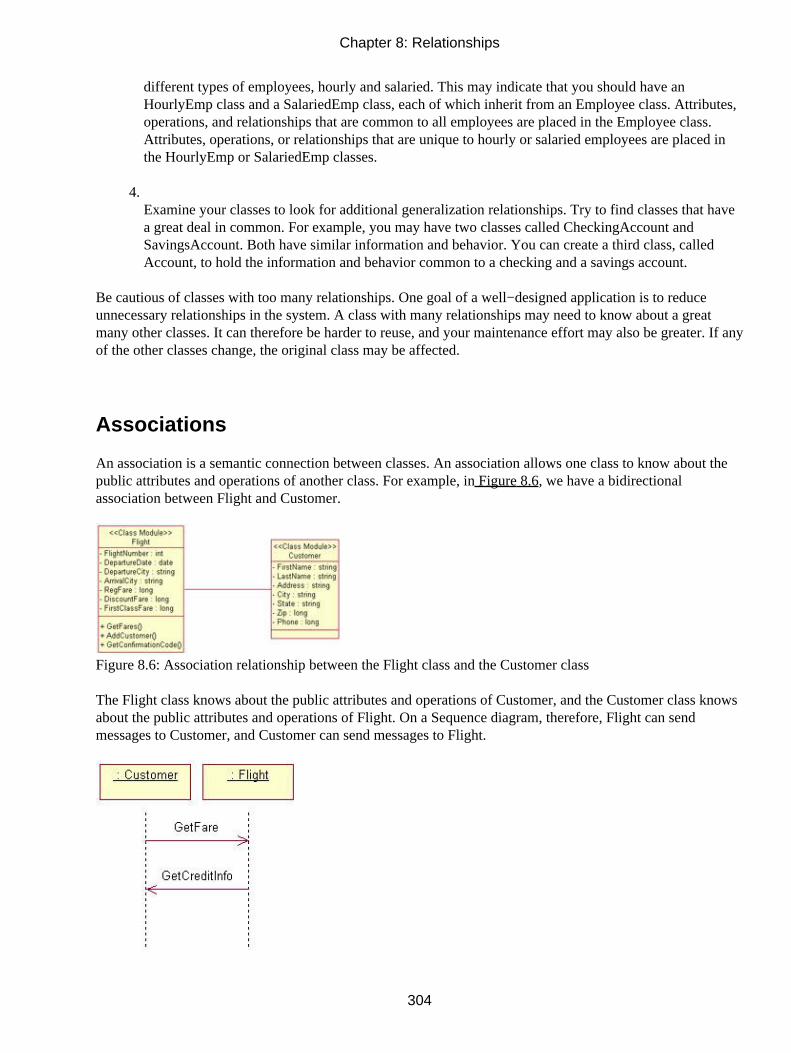
different types of employees, hourly and salaried. This may indicate that you should have anHourlyEmp class and a SalariedEmp class, each of which inherit from an Employee class. Attributes,operations, and relationships that are common to all employees are placed in the Employee class.Attributes, operations, or relationships that are unique to hourly or salaried employees are placed inthe HourlyEmp or SalariedEmp classes.
4. Examine your classes to look for additional generalization relationships. Try to find classes that havea great deal in common. For example, you may have two classes called CheckingAccount andSavingsAccount. Both have similar information and behavior. You can create a third class, calledAccount, to hold the information and behavior common to a checking and a savings account.
Be cautious of classes with too many relationships. One goal of a well−designed application is to reduceunnecessary relationships in the system. A class with many relationships may need to know about a greatmany other classes. It can therefore be harder to reuse, and your maintenance effort may also be greater. If anyof the other classes change, the original class may be affected.
Associations
An association is a semantic connection between classes. An association allows one class to know about thepublic attributes and operations of another class. For example, in Figure 8.6, we have a bidirectionalassociation between Flight and Customer.
Figure 8.6: Association relationship between the Flight class and the Customer class
The Flight class knows about the public attributes and operations of Customer, and the Customer class knowsabout the public attributes and operations of Flight. On a Sequence diagram, therefore, Flight can sendmessages to Customer, and Customer can send messages to Flight.
Chapter 8: Relationships
304

In the example above, the relationship is bidirectional. However, you will want to refine most of yourassociations to be unidirectional. Unidirectional relationships are easier to build and to maintain, and can helpyou find classes that can be reused. Let's look at the above example again, but this time the association isunidirectional. Figure 8.7 shows the unidirectional relationship.
Figure 8.7: Unidirectional association relationship
In this case, the Flight class knows about the public attributes and operations of Customer, but Customer doesnot know about the public attributes and operations of Flight. Messages on a Sequence or Collaborationdiagram can be sent by Flight and received by Customer, but cannot be sent by Customer.
You can determine the direction of an association by looking at the Sequence and Collaboration diagrams. Ifevery message on the Interaction diagrams is sent by Flight and received by Customer, there is aunidirectional relationship from Flight to Customer. If there is even one message from Customer to Flight,you will need a bidirectional relationship.
Unidirectional relationships can help you identify classes that are good candidates for reuse. If the associationbetween Flight and Customer is bidirectional, each class needs to know about the other; neither class can,therefore, be reused without the other. But assume instead that there is a unidirectional relationship fromFlight to Customer. Flight needs to know about Customer, so it can't be reused without Customer. However,Customer doesn't need to know about Flight, so Customer can be easily reused. Any class that has manyunidirectional relationships coming out of it is hard to reuse; any class that has only unidirectionalrelationships coming into it is easy to reuse, as shown in Figure 8.8.
Figure 8.8: Reuse with unidirectional associations
When you generate code for a bidirectional association, Rose will generate attributes in each class. In ourFlight and Customer example, Rose will place a Flight attribute inside Customer, and a Customer attributeinside Flight. Figure 8.9 is an example of the code generated for these two classes.
Chapter 8: Relationships
305

Figure 8.9: Code generated for a bidirectional association
If, instead, we have a unidirectional association, Rose will place a Customer attribute inside Flight, but not aFlight attribute inside Customer. Figure 8.10 is an example of the code generated for a unidirectionalassociation.
Figure 8.10: Code generated for a unidirectional association
Associations can also be reflexive. A reflexive association suggests that one instance of a class is related toother instances of the same class. For example, we may have a Person class. One person can be the parent ofone or more other people. Because there are separate instances of Person with a relationship to each other, wehave a reflexive association, as shown in Figure 8.11.
Figure 8.11: Reflexive association
Using Web Association Stereotypes
With the inclusion of web modeling, Rose now supports four stereotypes for associations. These are the link,submit, build, and redirect stereotypes.
The link stereotype is used to show a hypertext link between two client pages or from a client page to a serverpage. It is represented on a Class diagram as a unidirectional association with a stereotype of <<link>>:
Chapter 8: Relationships
306

The submit stereotype is used when a form sends the information in its fields to a server page for processing.This submittal of information is shown on a Class diagram as a unidirectional association relationship with astereotype of <<submit>>.
The build stereotype is used when a server page builds a client page. Once the client page has been built, itcan be displayed on the client browser. The relationship shows which server page builds which client page. Itis shown on a class diagram as a unidirectional relationship with a stereotype of <<build>>:
Finally, the redirect stereotype is used to show one page passing processing control to another page. A redirectrelationship is shown as a unidirectional association with a stereotype of <<redirect>>:
Creating Associations
In Rose, you create associations directly on a Class diagram. The Diagram toolbar includes buttons forcreating both unidirectional and bidirectional associations.
If you create a bidirectional association, you can later change it to a unidirectional association by changing itsnavigability. Later in this chapter, in the "Working with Relationships" section, we will discuss the detailedspecifications of an association, including navigability.
To create a bidirectional association on a Class diagram:
1.
Chapter 8: Relationships
307

Select the Association icon from the toolbox.
2. Drag the association line from one class to the other class.
OR
1. Select Tools → Create → Association.
2. Drag the association line from one class to the other class.
To create a unidirectional association on a Class diagram:
1. Select the Unidirectional Association icon from the toolbox.
2. Drag the association line from one class to the other class.
OR
1. Select Tools → Create → Unidirectional Association.
2. Drag the association line from one class to the other class.
To set the navigability of a relationship:
1. Right−click the desired relationship at the end to be navigated.
2. Select Navigable from the menu.
OR
1. Open the desired relationship's specification window.
2. Select the Role Detail tab for the end to be navigated.
3. Change the navigability using the Navigable check box.
To create a reflexive association on a Class diagram:
1.
Chapter 8: Relationships
308

Select the Association icon from the toolbox.
2. Drag the association line from the class to somewhere outside of the class.
3. Release the association line.
4. Drag the association line back into the class.
OR
1. Select Tools → Create → Association.
2. Drag the association line from the class to somewhere outside of the class.
3. Release the association line.
4. Drag the association line back into the class.
To add documentation to an association:
1. Double−click the desired association.
2. Select the General tab.
3. Enter documentation in the Documentation field.
OR
1. Select the desired association.
2. Select Browse → Specification.
3. Select the General tab.
4. Enter documentation in the Documentation field.
To change a relationship to an association:
1.
Chapter 8: Relationships
309

Select the desired relationship.
2. Select Edit → Change Into → Association.
Deleting Associations
There are two ways to delete an association. The first is to delete it from a single diagram. In this case, Rosestill knows the association exists, and keeps track of it behind the scenes. Although the association may bedeleted from one diagram, it may still exist on other Class diagrams.
The second way to delete an association is to remove it from the entire Rose model. In this case, therelationship is removed from all Class diagrams, and Rose no longer keeps track of it.
To delete an association from the diagram only:
1. Select the desired association.
2. Press the Delete key.
OR
1. Select the desired association.
2. Select Edit → Delete.
Note Deleting an association from the diagram does not delete it from the model.To delete an association from the model:
1. Select the desired association.
2. Press Ctrl+D.
OR
1. Select the desired association.
2. Select Edit → Delete from Model.
OR
1. Open the specification window for either class participating in the relationship.
2.
Chapter 8: Relationships
310

Select the Relations tab.
3. Right−click the relationship.
4. Select Delete from the shortcut menu.
Dependencies
A dependency relationship shows that a class references another class. Therefore, a change in the referencedclass specification may impact the using class. When there is a dependency between two classes, Rose doesnot add any attributes to the classes for the relationship, which is one of the differences between anassociation and a dependency.
Returning to our example above, assume there is a dependency relationship between Flight and Customer. Adependency relationship is shown as a dashed arrow, as shown in Figure 8.12.
Figure 8.12: Dependency relationship
When we generate code for these two classes, attributes will not be added to either class for the relationship,as shown in Figure 8.13. However, any language−specific statements needed to support the relationship willbe generated. For example, in C++, the necessary #include statements will be included in the generated code.
Chapter 8: Relationships
311

Figure 8.13: Code generated for a dependency relationship
The implication here is that Flight will need some other way to know that Customer exists. The direction ofthe arrow indicates that Flight depends on Customer. In other words, there is a Sequence or Collaborationdiagram in which Flight sends a message to Customer. Had there been a regular association between thesetwo, Flight would have a Customer attribute. To send a message to Customer, Flight would just look at itsown Customer attribute.
With a dependency, however, Flight won't have a Customer attribute. It therefore has to find out aboutCustomer some other way. There are three ways it can know about Customer. Customer could be global, inwhich case Flight would know it exists. Or, Customer could be instantiated as a local variable inside anoperation of Flight. Finally, Customer could be passed in as a parameter to some operation inside Flight.When there is a dependency, one of these three approaches must be taken.
Although we are now at the detailed coding level, this decision may affect the model. We may need to add anargument to an operation of Flight.
Chapter 8: Relationships
312

The second difference between an association and a dependency lies in the direction. Associations can bebidirectional, but dependencies are unidirectional. Dependencies are also used for relationships betweenpackages and between components. This will be discussed later in this chapter.
Creating Dependencies
After you've added associations, you may want to revisit them to see if any should be dependencies instead. Ifso, you can change the relationship from an association to a dependency using the method outlined below.(This is preferred if you have an association displayed in several diagrams, because Rose will change theassociation globally.)
To create a new dependency, you can use the Dependency icon on the Class Diagram toolbar.
To create a dependency on a Class diagram:
1. Select the Dependency icon from the toolbox.
2. Click the class to be dependent.
3. Drag the dependency line to the other class.
OR
1. Select Tools → Create → Dependency.
2. Click the class to be dependent.
3. Drag the dependency line to the other class.
To add documentation to a dependency:
1. Double−click the desired dependency.
2. Select the General tab.
3. Enter documentation in the Documentation field.
OR
1.
Chapter 8: Relationships
313

Select the desired dependency.
2. Select Browse → Specification.
3. Select the General tab.
4. Enter documentation in the Documentation field.
To change a relationship to a dependency on a Class diagram:
1. Select the desired relationship.
2. Select Edit → Change Into → Uses Dependency.
Deleting Dependencies
As with associations, there are two ways to delete a dependency. You can remove it from a single Classdiagram or from the entire model. The following are the procedures for deleting a dependency.
To delete a dependency from the diagram:
1. Select the desired dependency.
2. Press the Delete key.
OR
1. Select the desired dependency.
2. Select Edit → Delete.
Note Deleting a dependency from the diagram does not delete it from the model.To delete a dependency from the model:
1. Select the desired dependency.
2. Press Ctrl+D.
OR
1.
Chapter 8: Relationships
314

Select the desired dependency.
2. Select Edit → Delete from Model.
OR
1. Open the specification window for either class participating in the relationship.
2. Select the Relations tab.
3. Right−click the relationship.
4. Select Delete from the shortcut menu.
Package Dependencies
Dependencies can be drawn between packages as well as classes. A package dependency, like a classdependency, is drawn as a dashed arrow. Figure 8.14 is an example of a package dependency.
Figure 8.14: Package dependency
A package dependency from package A to package B suggests that some class in package A has aunidirectional relationship to some class in package B. In other words, some class in A needs to know aboutsome class in B.
This has reuse implications. If our dependencies look like this, package A depends on package B. Therefore,we can't just pick up package A and reuse it in another application. We would also have to pick up B andreuse it. Package B, on the other hand, is easy to reuse because it doesn't depend on anything else.
You can find package dependencies by examining the relationships on your Class diagram. If two classesfrom different packages have a relationship, their packages must have a relationship as well.
As you are creating package dependencies, try to avoid circular dependencies whenever possible. A circulardependency looks like Figure 8.15.
Chapter 8: Relationships
315

Figure 8.15: Circular dependency
This suggests that some class in A needs to know about some class in B, while some class in B needs to knowabout some class in A. In this case, neither package can be easily reused, and a change to one package mayaffect the other. We've lost some of the benefits of packaging classes with this approach—the packages aretoo interdependent. To break circular dependencies, you can split apart one package into two. In our example,we can take the classes in B that A depends on, and move them to another package we'll call C. Now ourpackage dependencies look like this:
Creating Package Dependencies
As you identify package dependencies, you can add them to your Rose model through a Class diagram.Typically, you will have one Class diagram which displays all of the packages and the relationships betweenthem. As with class dependencies, you use the Dependency toolbar button to draw the relationships.
To create a package dependency on a Class diagram:
1. Select the Dependency icon from the toolbox.
2. Drag the dependency line from the dependent package to the other package.
OR
1. Select Tools → Create → Dependency.
2. Drag the dependency line from the dependent package to the other package.
Chapter 8: Relationships
316

Deleting Package Dependencies
As with a class dependency, there are two ways to delete a package dependency—from a single Class diagramor from the entire model.
If you delete a package dependency, but classes from the two packages still have relationships to each other,you will have difficulty generating code. You can use the Report → Show Access Violations option to see ifthis has happened.
To delete a package dependency from a Class diagram:
1. Select the desired package dependency.
2. Press the Delete key.
OR
1. Select the desired package dependency.
2. Select Edit → Delete.
Aggregations
An aggregation is a stronger form of association. An aggregation is a relationship between a whole and itsparts. For example, a FlightList might be made up of Flights. In UML, an aggregation is shown as a lineconnecting the two classes, with a diamond next to the class representing the whole, as shown in Figure 8.16.
Figure 8.16: Aggregation relationship
One class may have several aggregation relationships with other classes. For example, a Car class might haverelationships to its many parts.
Chapter 8: Relationships
317

Like associations, aggregations can be reflexive, as shown in Figure 8.17. A reflexive aggregation suggeststhat one instance of a class is made up of one or more other instances of the same class. For example, whencooking, you may combine some ingredients, which form ingredients for other things. In other words, eachingredient can be made up of other ingredients.
Figure 8.17: Reflexive aggregation relationship
When you generate code for an aggregation, Rose will generate attributes to support the aggregation. In theCar example, the Car class will have attributes for the door, engine, tire, and all of the other parts in theaggregation relationship.
Creating Aggregations
Aggregations are created on the Class diagrams. To create an aggregation, you can use the Aggregation buttonon the Class Diagram toolbar.
To create an aggregation on a Class diagram:
1. Select the Unidirectional Aggregation icon from the toolbox.
2. Drag the aggregation line from the whole class to the part class.
OR
1. Select Tools → Create → Aggregation.
2. Drag the aggregation line from the whole class to the part class.
To create a reflexive aggregation on a Class diagram:
1. Select the Unidirectional Aggregation icon from the toolbox.
2. Drag the aggregation line from the class to somewhere outside of the class.
3. Release the aggregation line.
4.
Chapter 8: Relationships
318

Drag the aggregation line back into the class.
OR
1. Select Tools → Create → Aggregation.
2. Drag the aggregation line from the class to somewhere outside of the class.
3. Release the aggregation line.
4. Drag the aggregation line back into the class.
To add documentation to the aggregation:
1. Double−click the desired aggregation.
2. Select the General tab.
3. Enter documentation in the Documentation field.
OR
1. Select the desired aggregation.
2. Select Browse → Specification.
3. Select the General tab.
4. Enter documentation in the Documentation field.
To change a relationship to an aggregation on a Class diagram:
1. Select the desired relationship.
2. Select Edit → Change Into → Aggregation.
OR
1.
Chapter 8: Relationships
319

Open the relationship specification window for the desired relationship.
2. Select the Role Detail tab.
3. Select the Aggregate check box.
Deleting Aggregations
You can delete an aggregation either from a single Class diagram or from the entire model. Here we list theprocedures for both.
To delete an aggregation from the diagram:
1. Select the desired aggregation.
2. Press the Delete key.
OR
1. Select the desired aggregation.
2. Select Edit → Delete.
Note Deleting an aggregation from the diagram does not delete it from the model.To delete an aggregation from the model:
1. Select the desired aggregation.
2. Press Ctrl+D.
OR
1. Select the desired aggregation.
2. Select Edit → Delete from Model.
OR
1. Open the specification window for either class participating in the relationship.
2.
Chapter 8: Relationships
320

Select the Relations tab.
3. Right−click the relationship.
4. Select Delete from the shortcut menu.
Generalizations
A generalization is an inheritance relationship between two model elements such as classes, actors, use cases,and packages. It allows one class to inherit the public and protected attributes and operations of another class.For example, we may have the relationship shown in Figure 8.18.
Figure 8.18: Generalization relationship
In this example, we have two types of employees: hourly and salaried, both of which inherit from theEmployee class. The Employee class is known as the superclass, and the HourlyEmp and SalariedEmp classesare known as the subclasses. The arrow points from the subclass to the superclass.
The elements that are common to both types are placed in the Employee class. Both HourlyEmp andSalariedEmp inherit the Name, Address, and SSN attributes of the Employee class and the Hire() and Fire()operations of the Employee class.
Each subclass can have its own unique attributes, operations, and relationships in addition to those it inherits.For example, only hourly employees have an hourly rate, and only salaried employees have a salary.
Chapter 8: Relationships
321

Generalization relationships can save a great deal of time and effort in both development and maintenance. Inthe above example, you don't need to program and maintain two separate copies of the Hire() operation (onein HourlyEmp and one in SalariedEmp). Instead, you can create and maintain one copy of the operation. Anychanges you make to the operation will be automatically inherited by HourlyEmp and SalariedEmp, and anyother subclasses of Employee.
When you are defining your generalizations, you can build your inheritance structure either from the top downor the bottom up. To build the structure from the top down, look for classes that might have different types.For example, you would start with the Employee class and soon realize that there are different types ofemployees. To build the structure from the bottom up, look for classes with commonality. Here, you wouldstart with the HourlyEmp and SalariedEmp classes and then realize that they are similar. You would thencreate an Employee class to hold the common elements.
Be careful not to create an inheritance structure that isn't maintainable. A hierarchy with too many layers canbecome very difficult to maintain. Every change toward the top of the structure will ripple down through thehierarchy to the classes below. While this can be an advantage, it can also make change analysis and controleven more essential. In some languages, too many layers can also slow down the application.
Creating Generalizations
As you discover generalization relationships, you can add them to your Rose model using a Class diagram.Frequently, an organization will create a single Class diagram or two that are dedicated to the inheritancestructure. These Class diagrams will typically show only limited attribute or operation information.
As you add generalizations, you may need to move some of the attributes and operations. For example, youmay start with the HourlyEmp and SalariedEmp classes, each of which has an attribute called Address, andnow, you want to move the Address attribute up the structure to the Employee class. In the browser, you candrag the Address attribute from either the HourlyEmp or the Salaried−Emp class to the Employee class. Besure to remember to remove the other copy of Address from HourlyEmp or SalariedEmp.
To create a generalization on a Class diagram:
1. Select the Generalization icon from the toolbox.
2. Drag the generalization line from the subclass to the superclass.
OR
1. Select Tools → Create → Generalization.
2. Drag the generalization line from the subclass to the superclass.
To add documentation to a generalization:
1. Double−click the desired generalization.
2.
Chapter 8: Relationships
322

Select the General tab.
3. Enter documentation in the Documentation field.
OR
1. Select the desired generalization.
2. Select Browse → Specification.
3. Select the General tab.
4. Enter documentation in the Documentation field.
To change a relationship to a generalization:
1. Select the desired relationship.
2. Select Edit → Change Into → Generalization.
Deleting Generalizations
As with the other relationships, you can delete a generalization from a single diagram or from the model. Ifyou delete a generalization from the entire model, keep in mind that the attributes, operations, andrelationships of the superclass will no longer be inherited by the subclass. Therefore, if the subclass needsthose attributes, operations, or relationships, they will have to be added to the subclass.
To delete a generalization from the diagram:
1. Select the desired generalization.
2. Press the Delete key.
OR
1. Select the desired generalization.
2. Select Edit → Delete.
Note Deleting a generalization from the diagram does not delete it from the model.
Chapter 8: Relationships
323

To delete a generalization from the model:
1. Select the desired generalization.
2. Press Ctrl+D.
OR
1. Select the desired generalization.
2. Select Edit → Delete from Model.
OR
1. Open the specification window for either class participating in the relationship.
2. Select the Relations tab.
3. Right−click the relationship.
4. Select Delete from the shortcut menu.
Working with Relationships
In this section, we'll take a look at the detailed specifications of the relationships in Rose. In your model, youcan add things like association names, role names, and qualifiers to specify why the relationship exists.
Before you generate code, you should specify the relationship multiplicity; otherwise Rose will provide adefault. Most of the other specifications we present in this section, however, are optional. Rose will notify youif a required specification has not been set when you attempt to generate code.
Setting Multiplicity
Multiplicity indicates how many instances of one class are related to a single instance of another class at agiven point in time. For example, if we're looking at a course registration system for a university, we mayhave classes called Course and Student. There is a relationship between them; courses have students andstudents have courses. The questions answered by the multiplicity are "How many courses can a student takeat one time?" and "How many students can be enrolled in a single course at one time?"
Chapter 8: Relationships
324

Because the multiplicity answers both questions, the multiplicity indicators are included at both ends of therelationship. In the course registration example, we decide that each student can be enrolled in 0 to 4 classes,and each course can have 10 to 20 students. On a Class diagram, this would be shown as in Figure 8.19.
Figure 8.19: Relationship multiplicity
In this figure, the 0..4 means that each student can be enrolled in 0 through 4 classes, and the 10..20 meansthat each class can have 10 to 20 students.
Keep in mind that the multiplicity settings will let you know whether the relationship is optional. In ourexample above, a student can take from 0 to 4 courses at any one time. Therefore, someone is still considereda student if they have taken a semester off. Had the multiplicity been 1..4 instead, every student would berequired to take at least 1 course per semester. The multiplicity, therefore, implements business rules such as"every student must take at least one course per semester."
Typically, multiplicity between forms, screens, or windows will be 0..1 on each side of the relationship.Although this doesn't always hold true, this multiplicity would indicate that each form can exist independentlyof the other.
UML notations for multiplicity are as follows:
Multiplicity Meaning
* Many
0 Zero
1 One
0..* Zero or more
1..* One or more
0..1 Zero or one
1..1 Exactly oneOr, you can enter your own multiplicity, using one of the following formats:
Format Meaning
<number> Exactly <number>
<number 1>..<number 2> Between <number 1> and <number 2>
<number>..n <number> or more
<number 1>,<number 2> <number 1> or <number 2>
<number 1>, <number 2>..<number 3> Exactly <number 1> or between <number 2> and<number 3>
<number 1>..<number 2>,<number 3>..<number 4>Between <number 1> and <number 2> or between<number 3> and <number 4>
To set relationship multiplicity:
1. Right−click the desired relationship on one end.
2.
Chapter 8: Relationships
325

Select Multiplicity from the shortcut menu.
3. Select the desired multiplicity.
4. Repeat steps 1–3 for the other end of the relationship.
OR
1. Open the desired relationship's specification window.
2. Select the Role Detail tab for one end.
3. Change the multiplicity using the cardinality field.
4. Repeat steps 1–3 for the other end of the relationship.
Using Relationship Names
Relationships can be refined using relationship names or role names. A relationship name is usually a verb orverb phrase that describes why the relationship exists. For example, we may have an association between aPerson class and a Company class. From this, though, we might ask these questions: Why does thisrelationship exist? Is the person a customer of the company, an employee, or an owner? We can name therelationship employs to specify why the relationship exists. Figure 8.20 is an example of a relationship name.
Figure 8.20: Relationship name
Relationship names are optional, and are typically used only when the reason for the relationship is notobvious. Relationship names are shown along the relationship line.
In Rose, you can also set the relationship direction. In the example above, we can say that the companyemploys the person, but can't say that the person employs the company. You can set the name direction in therelationship specification window.
To set the relationship name:
1. Select the desired relationship.
2. Type in the desired name.
OR
1.
Chapter 8: Relationships
326

Open the desired relationship's specification window.
2. Select the General tab.
3. Enter the name in the Name field.
To set the name direction:
1. Open the desired relationship's specification window.
2. Select the Detail tab.
3. Set the name direction using the Name Direction field.
Using Stereotypes
Like other model elements, you can assign a stereotype to a relationship. Stereotypes are used to classifyrelationships. In particular, when modeling web applications, you may want to set the stereotypes of theassociation relationships. As we discussed earlier in this chapter, there are four stereotypes in the Rose WebModeler add−in: a link relationship, a submit relationship, a build relationship, and a redirect relationship. Alink relationship is used to show one page that contains a hyperlink to another. A submit relationship shows aform submitting information to a server page. A build relationship is used to show a server page building aclient page. Finally, a redirect relationship shows how processing control is passed from one page to another.
Stereotypes are shown along the association line and are enclosed in double angle brackets (<<>>). To set therelationship stereotype, you can use the General tab of the relationship specification window, as shown inFigure 8.21.
Chapter 8: Relationships
327

Figure 8.21: Relationship specification window
To set a relationship stereotype:
1. Open the desired relationship's specification window.
2. Select the General tab.
3. Enter the stereotype in the Stereotype field.
Using Roles
Role names can be used instead of relationship names in associations or aggregations to describe the reasonthe relationship exists. Returning to our Person and Company example, we can say that a Person playing therole of an employee is related to a Company. Role names are typically nouns or noun phrases, and are shownnext to the class playing the role. Typically, you would use either a relationship name or a role name, but notboth. Like relationship names, role names are optional, and are only used when the purpose of the relationshipis not obvious. Figure 8.22 shows an example of roles.
Chapter 8: Relationships
328

Figure 8.22: Roles in a relationship
You can add documentation to a role using the relationship specification window. Any documentation youadd to a role will be generated as a comment when you generate code. To view the role on the diagram,right−click the relationship and select the Role Name option, as shown in Figure 8.23.
Figure 8.23: Setting role documentation
To set a role name:
1. Right−click the desired association on the end to be named.
2. Select Role Name from the shortcut menu.
3. Type in the role name.
OR
1. Open the desired association's specification window.
2. Select the Role General tab for the role to be named.
3. Enter the role name in the Role field.
Chapter 8: Relationships
329

To add role documentation:
1. Open the desired association's specification window.
2. Select the Role General tab for the desired role.
3. Enter the documentation in the Documentation field.
Setting Export Control
In an association relationship, Rose will create attributes when you generate code. The visibility of thegenerated attributes is set through the Export Control field. As with other attributes, there are four visibilityoptions:
Public Indicates that the attribute will be visible to all other classes
Private Indicates that the attribute is not visible to any other class
Protected Suggests that the attribute is visible only to the class and its subclasses
Package or implementation Means that the attribute is visible to all other classes in the same package
In a bidirectional relationship, you can set the export control of two attributes, one created at each end of therelationship. In a unidirectional relationship, only one will need to be set. The export control can be set usingthe Role A General and Role B General tabs of the relationship specification window.
Chapter 8: Relationships
330

To set export control for a role:
1. Right−click the desired role's name.
2. Select Export Control from the shortcut menu.
OR
1. Open the desired relationship's specification window.
2. Select the Role General tab for the desired role.
3. Set the export control to Public, Protected, Private, or Implementation.
Using Static Relationships
As we mentioned earlier, Rose will generate attributes for association and aggregation relationships. A staticattribute is one that is shared by all instances of a class. You use the Static field to determine whether or notthe generated attributes will be static.
If you set one of the roles to be static, the associated attribute that is generated will be static. On the Classdiagram, the static role will appear with a dollar sign ($) in front of it, as shown in Figure 8.24.
Chapter 8: Relationships
331

Figure 8.24: Static role
To classify an association as static:
1. Right−click the desired end of the association to be static.
2. Select Static from the pop−up menu.
OR
1. Open the desired association's specification window.
2. Select the Detail tab for the role to be static.
3. Select the Static check box.
Using Friend Relationships
A friend relationship indicates that the Client class has access to the non−public attributes and operations ofthe Supplier class. You can set the friend property for an association, aggregation, dependency, orgeneralization. The source code for the Supplier class will include logic to allow the Client class to havefriend visibility.
For example, say we have a unidirectional association from a Person class to a Company class, and we've setthe Friend check box for the relationship. When we generate C++ code, the Company .h file will include theline "friend class Person." This suggests that the Person class has access to the non−public parts of theCompany class.
To classify a relationship as a friend:
1. Right−click the appropriate end of the desired relationship.
2. Select Friend from the pop−up menu.
OR
1. Open the desired relationship's specification window.
2. Select the Role Detail tab for the appropriate end.
3.
Chapter 8: Relationships
332

Select the Friend check box.
Setting Containment
The Containment field determines whether the generated attributes of an aggregation will be contained byvalue or by reference. In an aggregation, the whole class will have attributes added for each of the part classes.Whether these attributes are by value or by reference is set here.
A by−value attribute suggests that the whole and the part are created and destroyed at the same time. Forexample, if there is a by−value aggregation between a Window class and a Button class, the Window and theButton are created and destroyed at the same time. In UML, a by−value aggregation is shown with a filleddiamond, as shown in Figure 8.25.
Figure 8.25: By−value aggregation
A by−reference aggregation suggests that the whole and the part are created and destroyed at different times.If we have an EmployeeList class that is made up of Employees, a by−reference aggregation would suggestthat the Employee may or may not be around in memory, and the EmployeeList may or may not be around inmemory. If they are both there, they are related via an aggregation. The Employee and EmployeeList arecreated and destroyed at different times. A by−reference aggregation is shown with a clear diamond, as inFigure 8.26.
Figure 8.26: By−reference aggregation
To set containment:
1. Right−click the desired end of the association to set containment.
2. Select Containment from the pop−up menu.
3. Select the containment as By Reference, By Value, or Unspecified.
OR
1. Open the desired relationship's specification window.
2. Select the Role Detail tab for the desired role.
3. Select the containment as By Reference, By Value, or Unspecified, as shown in Figure 8.27.
Chapter 8: Relationships
333

Figure 8.27: Setting containment
Using Qualifiers
A qualifier is used to reduce the scope of an association. For example, we may have an association between aPerson class and a Company class. Suppose we want to say that for a given value of Person ID, there areexactly two related companies. We can add a qualifier called Person ID to the Person class. The diagramwould look like Figure 8.28.
Figure 8.28: Using a qualifier
To add a qualifier:
1. Right−click the desired association at the end to add a qualifier.
2. Select New Key/Qualifier from the pop−up menu.
3. Enter the new qualifier's name and type.
Chapter 8: Relationships
334

OR
1. Open the desired association's specification window.
2. Select the Role Detail tab for the desired role.
3. Right−click the Keys/Qualifiers box.
4. Select Insert from the pop−up menu.
5. Enter the new qualifier's name and type.
To delete a qualifier:
1. Open the desired association's specification window.
2. Select the Role Detail tab for the desired role.
3. Right−click the qualifier to be deleted.
4. Select Delete from the pop−up menu.
Using Link Elements
A link element, also known as an association class, is a place to store attributes related to an association. Forexample, we may have two classes, Student and Course. Where should the attribute Grade be placed? If it isinside the Student class, we will need to add an attribute to Student for every course the student is enrolled in.This can clutter the Student class. If we put the attribute in Course, we will need an additional attribute forevery student enrolled in the course.
To get around this problem, we can create an association class. The attribute Grade, because it's more relatedto the link between a student and a course than to each individually, can be placed in this new class. UMLnotation for an association class is shown in Figure 8.29.
Chapter 8: Relationships
335

Figure 8.29: Link element (association class)
To set a link element for the relationship:
1. Open the desired relationship's specification window.
2. Select the Detail tab.
3. Set the link element using the Link Element field.
Using Constraints
A constraint is some condition that must be true. In Rose, you can set constraints for the relationship or for asingle role. Any constraints you enter will be generated as comments in the generated code.
To set a relationship constraint:
1. Open the desired relationship's specification window, as shown in Figure 8.30.
Chapter 8: Relationships
336

Figure 8.30: Relationship constraints
2. Select the Detail tab.
3. Enter constraints in the Constraints field.
To add constraints to a role:
1. Open the desired relationship's specification window.
2. Select the Role Detail tab for the desired role.
3. Enter the constraints in the Constraints field, as shown in Figure 8.31.
Chapter 8: Relationships
337

Figure 8.31: Role constraints
Exercise
In this exercise, we will add the relationships between the classes that participate in the "Add Item toShopping Cart" use case.
Problem Statement
Once Karen had added the attributes and operations to the classes, she was nearly ready to generate code.First, though, she had to take a look at the relationships between the classes.
She examined the Sequence diagrams for any existing messages between two objects, which indicated theneed for a relationship between the classes. Any classes that communicated in the Sequence diagram needed arelationship on the Class diagram. Once she identified the relationships, she added them to the model.
Adding Relationships
Add relationships to the classes that participate in the "Add Item to Shopping Cart" use case.
Exercise Steps:
Setup
1.
Chapter 8: Relationships
338

Locate the Add Item to Shopping Cart Class diagram in the browser.
2. Double−click to open the diagram.
3. Look for a Unidirectional Association button on the Diagram toolbar. If one does not exist, continuethrough step 5. Otherwise, skip to the next section of the exercise.
4. Right−click the Diagram toolbar and select Customize from the shortcut menu.
5. Add the button labeled Creates a Unidirectional Association to the toolbar.
Add Associations
1. Select the Unidirectional Association toolbar button.
2. Draw an association from the CartInterface class to the CartMgr class.
3. Repeat steps 1 and 2 to draw the following associations:
♦ From CartMgr to ProductMgr
♦ From ProductMgr to ProductCollection
♦ From ProductCollection to Product
♦ From CartMgr to CartCollection
♦ From CartCollection to CartItem
4. Right−click the unidirectional association between the CartInterface class and the CartMgr class, nearthe CartInterface class.
5. Select Multiplicity → Zero or One from the shortcut menu.
6. Right−click the other end of the unidirectional association.
7.
Chapter 8: Relationships
339

Select Multiplicity → Zero or One from the shortcut menu.
8. Repeat steps 4–7 to add the remaining multiplicity to the diagram, as shown in Figure 8.32.
Figure 8.32: Associations for the "Add Item to Shopping Cart" use case
9. Right−click the unidirectional association between the CartCollection class and CartItem class, nearthe CartCollection class.
10. Select Aggregate from the shortcut menu.
11. Repeat steps 9 and 10 to add an aggregation between the ProductCollection class and Product class.
Summary
In this chapter, we discussed the different types of relationships in UML: associations, dependencies,aggregations, and generalizations. Each of these types of relationships can be added to a Rose model througha Class diagram.
Once the relationships have been added, you can add various details, such as relationship names, role names,qualifiers, and multiplicity. In the next chapter, we'll take a look at object behavior. We'll focus on a singleclass and examine the various states in which the class can exist and the ways the class transitions from onestate to another.
Chapter 8: Relationships
340

Chapter 9: Object BehaviorWe've looked at classes and their relationships; we'll now examine the life of a single object. A given objectcan exist in one or more states. For example, an employee can be employed, fired, on probation, on leave, orretired. An Employee object may behave differently in each of these states.
In this chapter, we discuss Statechart diagrams, which include information about the various states in whichan object can exist, how the object transitions from one state to another, and how the object behavesdifferently in each of the states.
• Creating a Statechart diagram
• Adding activities, entry actions, exit actions, events, and state histories to states
• Adding events, arguments, guard conditions, actions, and send events to transitions
• Adding start, stop, and nested states
Statechart Diagrams
A Statechart diagram shows the life cycle of a single object, from the time that it is created until it isdestroyed. These diagrams are a good way to model the dynamic behavior of a class. In a typical project, youdo not create a Statechart diagram for every class. In fact, many projects do not use them at all. Figure 9.1 isan example of a Statechart diagram for our Flight class.
Figure 9.1: Statechart diagram for a Flight class
In this chapter, we discuss the different pieces of notation in this diagram. Briefly, however, we can read thediagram as follows:
A flight begins in a Tentative state. Someone reviews the schedule to determine whether or not to include the
341

flight. If the schedule is rejected, the flight is deleted and no further action can be taken. If the schedule isapproved, the flight moves into a Scheduled status. The flight schedule is posted to the Internet, and as soonas it is 60 days or less before the flight, the flight becomes open. We can add and remove passengers from theflight, but as soon as the last seat is sold, the flight is full. If someone then cancels their reservation, the flightcan become open again. Ten minutes before takeoff, the flight is closed for reservations. If the plane has notyet arrived, the flight is delayed until either the plane arrives or it has been four hours. After four hours, theflight is canceled. If the plane has arrived, but there are fewer than 50 people, the flight is canceled. If theflight is canceled, the airline will find an alternate flight for the passengers. If the plane does arrive, it takesoff and lands, which is the conclusion of this particular flight.
If you have a class that has some significant dynamic behavior, it can be helpful to create a Statechart diagramfor it. A class with significant dynamic behavior is one that can exist in many states. In our airline example, aflight may be scheduled, open, full, or canceled.
To decide whether a class has significant dynamic behavior, begin by looking at its attributes. Consider howan instance of the class might behave differently with different values in an attribute. If you have an attributecalled Status, this can be a good indicator of various states. How does the object behave differently asdifferent values are placed in this attribute?
You can also examine the relationships of a class. Look for any relationships with a zero in the multiplicity.Zeroes indicate that the relationship is optional. Does an instance of the class behave differently when therelationship does or does not exist? If it does, you may have multiple states. For example, let's look at arelationship between a person and a company. If there is a relationship, the person is in an employed state. Ifthere is no relationship, the person may be fired or retired.
In Rose, no source code is generated from a Statechart diagram. These diagrams serve to document thedynamic behavior of a class so that developers and analysts will have a clear understanding of the behavior.The developers are ultimately responsible for implementing the logic outlined in the diagram. As with theother UML diagrams, Statechart diagrams give the team a chance to discuss and document the logic before itis coded.
Creating a Statechart Diagram
In Rose, you can create one or more Statechart diagrams per class. In the browser, the Statechart diagramsappear underneath the class. The Rose icon for a Statechart diagram in the browser is shown below:
To create a Statechart diagram:
1. Right−click the desired class in the browser.
2. Select New → Statechart Diagram from the pop−up menu.
Rose will create an entry under the class in the browser called State/Activity Model. Underneath this entrywill be a new Statechart diagram called NewDiagram. You can create additional Statechart or activitydiagrams for the class by right−clicking State/Activity Model in the browser and selecting New → StatechartDiagram or New → Activity Diagram.
Chapter 9: Object Behavior
342

Adding States
A state is one of the possible conditions in which an object may exist. You can examine two areas todetermine the state of an object: the values of the attributes and the relationships to other objects. Consider thedifferent values that can be placed in the attributes and the state of the object if a relationship does or does notexist. Our Flight class, for example, might have an attribute called NumPassengers. Consider how the flightbehaves depending upon the value of NumPassengers. If there are 0 passengers, should the flight be able toleave at all? What if there are 500 scheduled passengers on a flight that holds 150? What if there are only 50?10? 5? At what point does the flight go ahead, and at what point is it canceled?
We can also look at the attribute DepartureDate. If the departure date is three years in the future, do we letpassengers reserve the flight? We might want to put the flight in a Scheduled status until it's a little closer tothe departure date. On the other hand, we may want to open the flight immediately, even if it doesn't departfor three years. The business requirements will dictate the system behavior.
Examining attributes like these can help us determine what some of the states of the object might be. So far,we have states called Full, Open, and Scheduled. We may even want to include an Overbooked state if we canput 500 reservations on a 150−person flight.
We can also look at the relationships between the flight and other objects to look for states. If there is arelationship to a Schedule object, the flight has been scheduled. If there is no relationship to a Pilot object, wewill put the flight into the Canceled state.
As with other Rose elements, you can add documentation to a state. However, because code is not generatedfrom these diagrams, comments will not be inserted into generated code for state documentation.
In UML, a state is shown as a rounded rectangle:
To add a state:
1. Select State from the toolbox toolbar.
2. Click on the Statechart diagram where the state should appear.
OR
1. Select Tools → Create → State.
2. Click on the Statechart diagram where the state should appear.
To add documentation to a state:
1.
Chapter 9: Object Behavior
343

Double−click the desired state to open the state specification window.
2. Select the General tab.
3. Enter documentation in the Documentation field.
OR
1. Select the desired state.
2. Select Browse → Specification.
3. Select the General tab.
4. Enter documentation in the Documentation field.
Adding State Details
While an object is in a particular state, there may be some activity that it performs. A report may be generated,some calculation may occur, or an event may be sent to another object. For example, while a flight is in theScheduled state, it may check the current date periodically to see when it is 60 days before the flight date. Assoon as it is 60 days before, the flight will be moved to the Open state. In Rose, you can include this type ofinformation in the model through the state specification window.
There are five types of information you can include for a state: an activity, an entry action, an exit action, anevent, or a state history. Let's look at each of these in the context of our example. Figure 9.2 is the Statechartdiagram for the Flight class.
Figure 9.2: Statechart diagram for Flight class
Chapter 9: Object Behavior
344

Activity
An activity is some behavior that an object carries out while it is in a particular state. For example, when anaccount is in the Closed state, the account holder's signature card is pulled. When a flight is in a Canceledstate, the airline tries to find alternate flights for its customers. An activity is an interruptible behavior. It mayrun to completion while the object is in that state, or it may be interrupted by the object moving to anotherstate.
An activity is shown inside the state itself, preceded by the word "do" and a slash.
Entry Action
An entry action is a behavior that occurs while the object is transitioning into the state. Using our flightexample, as soon as a flight becomes scheduled, the system posts the schedule to the Internet. This happenswhile the flight is transitioning into the Scheduled state. Unlike an activity, an entry action is considered to benoninterruptible. While the posting of a schedule record for use on the Internet is technically interruptible, ithappens very fast and the user does not have the ability to easily cancel the transaction while it is occurring.Therefore, it can be modeled as an action. There is a fine line between an action and an activity, but thedistinguishing characteristic is whether or not it is interruptible.
An entry action is shown inside the state, preceded by the word "entry" and a slash.
Exit Action
An exit action is similar to an entry action. However, an exit action occurs as part of the transition out of astate. For example, when the plane lands and transitions out of the In Flight state, the system records thelanding time. Like an entry action, an exit action is considered to be noninterruptible.
An exit action is shown inside the state, preceded by the word "exit" and a slash.
The behavior in an activity, entry action, or exit action can include sending an event to some other object. Forexample, if the flight is delayed for more than four hours, the flight object may need to send an event to aflight scheduler object, which will automatically reschedule the flight for another day. In this case, theactivity, entry action, or exit action is preceded by a caret (^). The diagram would then read:
Chapter 9: Object Behavior
345

Do/ ^Target.Event(Arguments)
where Target is the object receiving the event, Event is the message being sent, and Arguments are parametersof the message being sent. In Rose, you can add all of these details to a send event.
An activity may also happen as a result of some event being received. For example, an account may be in theOpen state. When some event occurs, the activity will be run.
All of these items can be added to your Rose model through the action specification window, as shown inFigure 9.3.
Figure 9.3: Action specification window
To add an activity:
1. Open the specification window for the desired state.
2. Select the Action tab.
3. Right−click the Actions box.
4. Select Insert from the pop−up menu.
5. Double−click the new action.
6.
Chapter 9: Object Behavior
346

Enter the action in the Actions field.
7. In the When box, select Do to make the new action an activity.
To add an entry action:
1. Open the specification window for the desired state.
2. Select the Action tab.
3. Right−click the Actions box.
4. Select Insert from the pop−up menu.
5. Double−click the new action.
6. Enter the action in the Actions field.
7. In the When box, select On Entry.
To add an exit action:
1. Open the specification window for the desired state.
2. Select the Action tab.
3. Right−click on the Actions box.
4. Select Insert from the pop−up menu.
5. Double−click the new action.
6. Enter the action in the Actions field.
7. In the When box, select On Exit.
Chapter 9: Object Behavior
347

To add an action that occurs on a specific event:
1. Open the specification window for the desired state.
2. Select the Action tab.
3. Right−click the Actions box.
4. Select Insert from the pop−up menu.
5. Double−click the new action.
6. Enter the action in the Actions field.
7. In the When box, select On Event.
8. Enter the event that triggers the action, along with any arguments of the event and any guardconditions that control whether or not the action should occur. If the guard condition is true, the actionwill occur on the event. If not, the action will not occur, even if the event happens.
To send an event:
1. Open the specification window for the desired state.
2. Select the Detail tab.
3. Right−click the Actions box.
4. Select Insert from the pop−up menu.
5. Double−click the new action.
6. Select Send Event as the type.
7. Enter the event, arguments, and target in their respective fields.
Chapter 9: Object Behavior
348

Adding Transitions
A transition is a movement from one state to another. The set of transitions on a diagram shows how theobject moves from one state to another. On the diagram, each transition is drawn as an arrow from theoriginating state to the succeeding state.
Transitions can also be reflexive. Something may happen that causes an object to transition back to the state itis currently in. For example, when we add a passenger to an open flight or remove a passenger, the flight isstill open. Reflexive transitions are shown as an arrow starting and ending on the same state.
To add a transition:
1. Select Transition from the toolbox toolbar.
2. Click on the state where the transition begins.
3. Drag the transition line to the state where the transition ends.
To add a reflexive transition:
1. Select Transition to Self from the toolbox toolbar.
2. Click on the state where the reflexive transition occurs.
OR
1. Select Tools → Create → Transition to Self.
2. Click on the state where the reflexive transition occurs.
To add documentation to a transition:
1.
Chapter 9: Object Behavior
349

Double−click the desired transition to open the specification window.
2. Select the General tab.
3. Enter documentation in the Documentation field.
Adding Transition Details
There are various specifications you can include for each transition. These include events, arguments, guardconditions, actions, and send events. Let's look at each of these, again in the context of our airline example.Figure 9.2 from earlier in this chapter shows the Statechart diagram for a Flight class.
Event
An event is something that causes a transition from one state to another to occur. In the airline example, theevent Land transitions the flight from an In Flight status to a Landed status. If the flight was Delayed, itbecomes Closed once the Plane Arrived event happens. An event is shown on the diagram along the transitionarrow.
On the diagram, an event can be drawn using an operation name or simply using an English phrase. In theairline example, all events are given English names. If you use operations instead, the Add Passenger eventmight be written as AddPassenger().
Events can have arguments. For example, when removing a passenger, we will need the name of thepassenger to be removed. The Remove Passenger event may therefore have an argument calledPassengerName. In your Rose model, you can add arguments to your events.
Most transitions will have events—the events are what cause the transition to occur in the first place.However, you can also have an automatic transition, which has no event. With an automatic transition, anobject automatically moves from one state to another as soon as all the entry actions, activities, and exitactions have occurred.
Guard Condition
A guard condition controls when a transition can or cannot occur. In the airline example, adding a passengerwill move the flight from the Open to the Full state, but only if the last seat was sold. The guard condition inthis example is "Last seat was sold."
A guard condition is drawn along the transition line, after the event name, and enclosed in square brackets.
Chapter 9: Object Behavior
350

Guard conditions are optional. If there is more than one automatic transition out of a state, however, theremust be mutually exclusive guard conditions on each automatic transition. This will help the reader of thediagram understand which path is automatically taken.
Action
An action, as we mentioned above, is a noninterruptible behavior that occurs as part of a transition. Entry andexit actions are shown inside states, because they define what happens every time an object enters or leaves astate. Most actions, however, will be drawn along the transition line, because they won't apply every time anobject enters or leaves a state.
For example, when transitioning from the Scheduled state to the Open state, we may want to initialize thenumber of passengers at 0. This initialization can happen while the transition is occurring, and can thereforebe modeled as an action.
An action is shown along the transition line, after the event name, and preceded by a slash.
An event or action may be a behavior that occurs inside the object or a message that is sent to another object.If an event or action is sent to another object, it is preceded by a caret (^) on the diagram.
To add an event:
1. Double−click the desired transition to open the specification window.
2. Select the General tab.
3. Enter the event in the Event field.
To add arguments to an event:
1. Double−click the desired transition to open the specification window.
2.
Chapter 9: Object Behavior
351

Select the General tab.
3. Enter the arguments in the Arguments field.
To add a guard condition:
1. Double−click the desired transition to open the specification window.
2. Select the Detail tab.
3. Enter the guard condition in the Condition field.
To add an action:
1. Double−click the desired transition to open the specification window.
2. Select the Detail tab.
3. Enter the action in the Action field.
To send an event:
1. Double−click the desired transition to open the specification window.
2. Select the Detail tab.
3. Enter the event in the Send Event field.
4. Enter any arguments in the Send Arguments field.
5. Enter the target in the Send Target field.
Adding Special States
There are two special states that can be added to the diagram: the start state and the stop state.
Chapter 9: Object Behavior
352

Start State
The start state is the state the object is in when it is first created. In the airline example, a flight begins in theTentative state. A start state is shown on the diagram as a filled circle.
A transition is drawn from the circle to the initial state.
A start state is mandatory: the reader of the diagram will need to know what state a new object is in. Therecan be only one start state on the diagram.
To add a start state:
1. Select Start State from the toolbox toolbar.
2. Click on the Statechart diagram where the start state should appear.
Stop State
The stop state is the state an object is in when it is destroyed. A stop state is shown on the diagram as abull's−eye.
Stop states are optional, and you can add as many stop states as you need.
To add a stop state:
1. Select End State from the toolbox toolbar.
2. Click on the Statechart diagram where the stop state should appear.
Using Nested States and State History
To reduce clutter on your diagram, or as a design decision, you can nest one or more states inside another. Thenested states are referred to as substates, while the larger state is referred to as a superstate.
If two or more states have an identical transition, they can be grouped together into a superstate. Then, ratherthan maintaining two identical transitions (one for each state), the transition can be moved to the superstate.Figure 9.4 is a portion of our Statechart diagram for the Flight class. As you can see, the flight moves into theClosed state 10 minutes before takeoff, regardless of whether it was in the Open or Full state before.
Chapter 9: Object Behavior
353

Figure 9.4: Statechart diagram without nested states
To reduce the number of arrows on the diagram, we can create a superstate around Open and Full, and thenjust model a single transition to the Closed state. Figure 9.5 is the same portion of the diagram with nestedstates. (As you can see, superstates can help to reduce the clutter on a Statechart diagram.)
Figure 9.5: Statechart diagram with nested states
At times, you may need the system to remember which state it was last in. If you have three states in asuperstate and then leave the superstate, you may want the system to remember where you left off inside thesuperstate. In our example, if we want to temporarily suspend reservations while the system is undergoingroutine maintenance, we may transition to a SuspendReservations state while the maintenance is occurring.Once the maintenance is done, we want to return to whatever state the flight was in before the maintenancestarted.
There are two things you can do to resolve this issue. The first is to add a start state inside the superstate. Thestart state will indicate where the default starting point is in the superstate. The first time the object enters thatsuperstate, this is where the object will be.
Chapter 9: Object Behavior
354

The second is to use state history to remember where the object was. If the History option is set, an object canleave a superstate and then return and pick up right where it left off. The History option is shown with a small"H" in a circle at the corner of the diagram, as shown in Figure 9.6.
Figure 9.6: Superstate history
To nest a state:
1. Select State from the toolbox.
2. Click on the state in which to nest the new state.
To use state history:
1. Open the specification window for the desired state.
2. Select the General tab.
3. Select the State/Activity History check box.
4. If you have states within states within states, you can apply the history feature to all nested stateswithin the superstate. To do so, select the Substate/Activity History check box.
Exercise
In this exercise, we will create a Statechart diagram for the Product class.
Problem Statement
In designing the Product class, Karen realized that it was a class that may require special attention. Many ofthe requirements varied significantly as the state of a product changed. For example, products that werebackordered could not be purchased.
Chapter 9: Object Behavior
355

To be sure the design was sound, she sat down with the other developers in the group and worked out aStatechart diagram for the class. With this information, the developers had a very good sense of what it wasgoing to take to code the class.
Create a Statechart Diagram
Create the Statechart diagram shown in Figure 9.7 for the Order class.
Figure 9.7: Statechart diagram for the Product class
Exercise Steps:
Create the Diagram
1. Locate the Product class in the browser.
2. Right−click the class and select New Statechart Diagram.
Add the Start and Stop States
1. Select Start State from the toolbox.
2. Place the state on the diagram.
3. Select End State from the toolbox.
4. Place the state on the diagram.
Chapter 9: Object Behavior
356

Add the States
1. Select State from the toolbox.
2. Place the state on the diagram.
3. Name the state Ordered.
4. Select State from the toolbox.
5. Place the state on the diagram.
6. Name the state Inventoried.
7. Select State from the toolbox.
8. Name the state Out of Stock.
9. Select State from the toolbox.
10. Name the state Selected for Purchase.
11. Select State from the toolbox.
12. Place the state on the diagram.
13. Name the state Purchased.
Add Transitions
1. Select Transition from the toolbox.
2. Click the Start State.
3. Drag the transition line to the Ordered state.
4.
Chapter 9: Object Behavior
357

Repeat steps 1–3 to add the following transitions:
♦ Ordered to Out of Stock
♦ Ordered to Inventoried
♦ Inventoried to Selected for Purchase
♦ Selected for Purchase to Inventoried
♦ Selected for Purchase to Purchased
♦ Purchased to End State
♦ Out of Stock to End State
♦ Inventoried to End State
Add Transition Details
1. Double−click the Ordered to Out of Stock transition to open the specification.
2. Select the Detail tab.
3. In the Guard Condition field, enter backordered.
4. Click OK to close the specification.
5. Repeat steps 1–4 to add the guard conditions to the following transitions:
♦ [received] between Ordered and Inventoried
♦ [in shopping cart] between Inventoried and Selected for Purchase
♦ [paid] between Selected for Purchase and Purchased
Chapter 9: Object Behavior
358

Summary
In this chapter, we took a look at the Statechart diagram, another of the UML diagrams supported by Rose.Although source code is not generated from these diagrams, they can prove invaluable when examining,designing, and documenting the dynamic behavior of a class.
A Statechart diagram shows the various states in which an object can exist, how the object moves from onestate to another, what happens in each state, and what happens during the transitions from one state to another.All of this information is part of the detailed design of the class. The developers can use this information whenprogramming the class.
In Rose, you can create a Statechart diagram for a class, an operation, a package, or a use case. You can createas many Statechart diagrams per class as you'd like to show the states and transitions for the class. Not everyclass will need a Statechart diagram, only those with significant dynamic behavior. To determine whether aclass has significant dynamic behavior, you can examine the values its attributes can have and therelationships the class can have.
In the next chapter, we'll prepare for source code generation by examining the Component view of Rose. Inthe Component view, we'll move from the logical design to the physical design and look at the code libraries,executable files, and other components of a system.
Chapter 9: Object Behavior
359

Chapter 10: Component ViewWe move now to the Component view of Rose. In the Component view, we'll focus on the physicalorganization of the system. First, we'll decide how the classes will be organized into code libraries. Then, we'lltake a look at the different executable files, dynamic link library (DLL) files, and other runtime files in thesystem. We won't concern ourselves yet with where the different files will be placed on the network. We'llconsider these issues in the Deployment view.
• Exploring types of components
• Creating components and mapping classes to components
• Using Component diagrams
What Is a Component?
A component is a physical module of code. Components can include both source code libraries and runtimefiles. For example, if you are using C++, each of your .cpp and .h files is a separate component. The .exe filethat you create after the code is compiled is also a component.
Before you generate code, you map each of your files to the appropriate component(s). In C++, for example,each class is mapped to two components—one representing the .cpp file for that class and one representing the.h file. In Java, you map each class to a single component, representing the .java file for that class. When yougenerate code, Rose will use the component information to create the appropriate code library files.
Once the components are created, they are added to a Component diagram and relationships are drawnbetween them. The only type of relationship between components is a dependency. A dependency suggeststhat one component must be compiled before another. We'll look at this in more detail in the "AddingComponent Dependencies" section later in this chapter.
Types of Components
In Rose, you can use several different icons to represent the different types of components. As we mentionedearlier, there are two primary types of components: source code libraries and runtime components. Withineach of these two groups are a number of different component icons you can use. Let's start by looking at thesource code library icons:
Component The Component icon represents a software module with a well−defined interface. In thecomponent specification, you specify the type of component in the Stereotype field (e.g., ActiveX, Applet,Application, DLL, and Executables). See Table 10.1 in the stereotypes section for a discussion of the differentstereotypes you can use with this icon.
360

Subprogram Specification and Body These icons represent a subprogram's visible specification and theimplementation body. A subprogram is typically a collection of subroutines. Subprograms do not containclass definitions.
Main Program The Main Program icon represents the main program. A main program is the file thatcontains the root of a program. In PowerBuilder, for example, this is the file that contains the applicationobject.
Package Specification and Body A package is the implementation of a class. A package specification is aheader file, which contains function prototype information for the class. In C++, package specifications arethe .h files. In Java, you use the Package Specification icon to represent the .java files.
A package body contains the code for the operations of the class. In C++, package bodies are the .cpp files.
Chapter 10: Component View
361

There are additional Component icons that are used for runtime components. Runtime components includeexecutable files, DLL files, and tasks.
Task Specification and Body These icons represent packages that have independent threads of control. Anexecutable file is commonly represented as a task specification with a .exe extension.
Database This icon represents a database, which may contain one or more schemas. On a Componentdiagram, a database is shown with the following icon:
In addition to modeling the component itself, you can model the relationship between a component and itsinterface. On a Component diagram, a component with its interface would look like this:
Component Diagrams
A Component diagram is a UML diagram that displays the components in the system and the dependenciesbetween them. Figure 10.1 is an example of a Component diagram.
Chapter 10: Component View
362

Figure 10.1: Component diagram
With this diagram, the staff responsible for compiling and deploying the system will know which codelibraries exist and which executable files will be created when the code is compiled. Developers will knowwhich code libraries exist and what the relationships are between them. The component dependencies will letthose who are responsible for compiling know in which order the components need to be compiled.
In the example in Figure 10.1, there are four components. The FlightServer component realizes the classesCustomer, Flight, and FlightList, all of which are on the server. The Flight component realizes the serverpages and client pages that are responsible for searching for flights and displaying flight information. TheCredit component realizes the CreditForm class, and the Reservation component realizes the ReserveSeat andConfirmationForm server and client pages.
Creating Component Diagrams
In Rose, you can create Component diagrams in the Component view. Once the diagrams are created, you caneither create components directly on the diagram or drag existing components from the browser to thediagram.
In the browser, Component diagrams are displayed with the following icon:
To create a Component diagram in the Component view:
1. In the browser, right−click the package that will contain the Component diagram.
2. Select New → Component Diagram from the pop−up menu.
3. Enter the name of the new Component diagram.
OR
1. Select Browse → Component Diagram. This displays the Select Component Diagram window.
2.
Chapter 10: Component View
363

Select the desired package.
3. Select <New> from the Component Diagram box and click OK.
4. Enter the name of the new Component Diagram and click OK.
To delete a Component diagram:
1. In the browser, right−click the Component diagram.
2. Select Delete from the pop−up menu.
OR
1. Select Browse → Component Diagram. This displays the Select Component Diagram window.
2. Select the desired package.
3. Select the component to delete.
4. Click the Delete button.
Adding Components
Once you've created the Component diagram, the next step is to add components. You begin by creating ageneric component and then assigning the appropriate stereotype to it. In the Component Diagram toolbar,buttons are available for all the different types of icons listed in the earlier section titled "Types ofComponents."
You can add documentation to the components as well. Documentation may include a description of thepurpose of the component or a description of the class(es) in the component.
Like classes, components can be packaged together to organize them. Typically, you create one Componentview package for each Logical view package. For example, if a Logical view package called Orders containsclasses called Order, OrderItem, and OrderForm, the corresponding Component view package would containthe components that hold the Order, OrderItem, and OrderForm classes.
To add a component:
1. Select Component from the toolbox toolbar.
2.
Chapter 10: Component View
364

Click on the diagram where the new component will be placed.
3. Enter a name for the new component.
OR
1. Select Tools → Create → Component.
2. Click on the diagram where the new component will be placed.
3. Enter a name for the new component.
OR
1. In the browser, right−click the package to contain the component.
2. Select New → Component from the pop−up menu.
3. Enter a name for the new component.
To add documentation to a component:
1. Right−click the desired component.
2. Select Open Specification from the pop−up menu. This opens the component's specification window.
3. Select the General tab.
4. Enter documentation in the Documentation field.
OR
1. Double−click the desired component. This opens the component's specification window.
2. Select the General tab.
3. Enter documentation in the Documentation field.
Chapter 10: Component View
365

OR
1. Select the desired component.
2. Select Browse → Specification. This opens the component's specification window.
3. Select the General tab.
4. Enter documentation in the Documentation field.
OR
1. Select the desired component.
2. Enter documentation in the documentation window.
To delete a component from the diagram only:
1. Select the component in the diagram.
2. Press Delete.
Note The component has been removed from the diagram, but still exists in the browser and on otherComponent diagrams.
To delete a component from the model:
1. Select the component on a Component diagram.
2. Select Edit → Delete from Model, or press Ctrl+D.
OR
1. Right−click the component in the browser.
2. Select Delete from the shortcut menu.
Note Rose will remove the component from all Component diagrams, as well as from the browser.
Chapter 10: Component View
366

Adding Component Details
As with other Rose model elements, there are a number of detailed specifications you can add to eachcomponent. These include stereotypes, languages, declarations, and classes.
Stereotypes
The first detail is a component stereotype. The stereotype controls which icon will be used to represent thecomponent.
As listed earlier, the stereotypes are <none> (which uses the Component icon), subprogram specification,subprogram body, main program, package specification, package body, executable, DLL, task specification,and task body.
In addition, Rose includes a number of other stereotypes for the different languages it supports. Thelanguage−specific stereotypes available in Rose are included in Table 10.1.
Table 10.1: Language−Specific Component Stereotypes
Language Stereotypes
Java EJBDeploymentDescriptor, EJB JAR, ServletDeploymentDescriptor,and WAR
Oracle8 Database, Schema
Visual Basic ActiveX ControlYou can create additional stereotypes if you'd like to represent new types of components in your particularprogramming language and application.
To assign a stereotype:
1. Open the desired component's standard specification window.
2. Select the General tab, as shown in Figure 10.2.
Chapter 10: Component View
367

Figure 10.2: Assigning a stereotype to a component
3. Enter the stereotype in the Stereotype field.
OR
1. Select the desired component.
2. Type the stereotype within the double angle brackets: << Name >>.
If the component is a Java, XML, or CORBA component, an additional component specification window isprovided, as shown below:
Chapter 10: Component View
368

Languages
In Rose, you can assign languages on a component−by−component basis. Therefore, you can generate part ofyour model in C++, part in Java, part in Visual Basic, and so on, provided you have the Enterprise version ofRose installed.
Rose Enterprise contains add−ins for ANSI C++, Ada 83, Ada 95, CORBA, C++, Java, Visual Basic, VisualC++, Web Modeler, XML/DTD, and Oracle 8. Many more add−ins are available from various vendors toextend the capabilities of Rose. Add−ins for other languages (PowerBuilder, Forte, Visual Age for Java, etc.)may be purchased as well. For a complete list of Rose Link Partners, visit the Rational Rose website athttp://www.rational.com/.
To assign a language:
1. Open the desired component's standard specification window.
2. Select the General tab.
3. Enter the language in the Language field.
Declarations
In Rose, there is a place to include supplementary declarations that will be added during code generation foreach component. Declarations include language−specific statements that are used to declare variables, classes,and so on. A C++ #include statement is also considered a declaration.
To add declarations:
1. Open the desired component's standard specification window.
2.
Chapter 10: Component View
369

Select the Detail tab, as shown in Figure 10.3.
Figure 10.3: Adding declarations to a component
3. Enter the declarations in the Declarations field.
Classes
Before code can be generated for a class, it must be mapped to a component. This mapping helps Rose knowin which physical file the code for the class should be stored.
You can map one or more classes to each component. After you have mapped a class to a component, thecomponent name will appear in parentheses after the class name in the Logical view.
Chapter 10: Component View
370

To map classes to a component:
1. Open the desired component's standard specification window.
2. Select the Realizes tab, as shown in Figure 10.4.
Chapter 10: Component View
371

Figure 10.4: Mapping classes to a component
3. Right−click the class to map.
4. Select Assign from the pop−up menu.
OR
1. In the browser, select the class to map.
2. Drag the class to the desired component, either in the browser or on a diagram.
Adding Component Dependencies
The only type of relationship that exists between components is a component dependency. A componentdependency suggests that one component depends on another. A component dependency is drawn as a dashedarrow between the components:
In this example, Component A depends upon Component B. In other words, there is some class in A thatdepends on some class in B.
These dependencies have compilation implications. In this example, because A depends on B, A cannot becompiled until B has been compiled. Someone reading this diagram will know that B should be compiled first,followed by A.
As with package dependencies, you want to avoid circular dependencies with components. If A depends on B,and B depends on A, you cannot compile either until the other has been compiled. Thus, you have to treat thetwo as one large component. All circular dependencies should be removed before you attempt to generatecode.
The dependencies also have maintenance implications. If A depends on B, any change to B may have animpact on A. Maintenance staff can use this diagram to assess the impact of a change. The more componentsthat a single component depends on, the more likely it is to be affected by a change.
Finally, the dependencies will let you know what may or may not be easily reused. In this example, A isdifficult to reuse. Because A depends on B, you cannot reuse A without also reusing B. B, on the other hand,is easy to reuse, since it does not depend on any other components. The fewer components that a singlecomponent depends on, the easier it is to reuse.
To add a component dependency:
1. Select the Dependency icon from the toolbox.
2.
Chapter 10: Component View
372

Drag the dependency line from the Client component to the Supplier component.
OR
1. Select Tools → Create → Dependency.
2. Drag the dependency line from the Client component to the Supplier component.
To delete a component dependency:
1. Select the desired component dependency.
2. Press the Delete key.
OR
1. Select the desired component dependency.
2. Select Edit → Delete.
Exercise
In this exercise, we will create the Component diagram for the shopping cart application. At this point, we'veidentified the classes that are needed for the "Add Item to Shopping Cart" use case. As other use cases arebuilt, new components will be added to the diagram.
Problem Statement
With the analysis and design completed, Dan, one of the members of the deployment team, created theComponent diagrams. By now, the team had decided to use Java, so he set about creating the appropriatecomponents for each class.
Figure 10.5 shows the main Component diagram for the entire system. This main diagram focuses on thepackages of components you will create.
Chapter 10: Component View
373

Figure 10.5: Main Component diagram
Figure 10.6 includes all of the components in the Entities package. These are the components that will containthe classes in the Entities package in the Logical view.
Figure 10.6: Entities package Component diagram
Figure 10.7 includes the components in the Control package. These components will contain the classes in theControl package in the Logical view.
Chapter 10: Component View
374

Figure 10.7: Control package Component diagram
Figure 10.8 includes the components in the Boundaries package. These components will contain the classes inthe Boundaries package in the Logical view.
Figure 10.8: Boundaries package Component diagram
Figure 10.9 shows all of the components in the system. We've named this diagram the System Componentdiagram. With this one diagram, you can see all of the dependencies between all of the components in thesystem.
Chapter 10: Component View
375

Figure 10.9: System Component diagram
Exercise Steps:
Create the Component Packages
1. Right−click the Component view in the browser.
2. Select New → Package.
3. Name the new package Entities.
4. Repeat steps 1–3 for packages Boundaries and Control.
Add the Packages to the Main Component Diagram
1. Open the main Component diagram by double−clicking it.
2. Drag the Entities, Boundary, and Control packages from the browser to the main Component diagram.
Draw Package Dependencies
1.
Chapter 10: Component View
376

Select Dependency from the toolbox.
2. On the main Component diagram, click the Entities package.
3. Drag the dependency to the Control package.
4. Repeat steps 1–3 to add a dependency from the Control package to the Boundaries package.
Add the Components for the Packages and Draw Dependencies
1. Double−click the Entities package in the main Component diagram to open the main Componentdiagram for the Entities package.
2. Select Package Specification from the toolbox.
3. Place the package specification on the diagram.
4. Enter the name of the package specification as CartCollection.
5. Repeat steps 2–4 to add the CartItem, ProductCollection, and ProductItem package specifications.
6. Select Dependency from the toolbox.
7. Click on the CartItem package specification.
8. Drag the dependency line to the CartCollection package specification.
9. Repeat steps 6−8 to add dependencies from the ProductItem package specification to theProduct−Collection package specification and from the ProductItem package specification to theCartItem package specification.
10. Use this method to create the following components and dependencies:
♦ CartInterface package specification for the Boundaries package
♦ CartMgr package specification for the Control package
♦
Chapter 10: Component View
377
ProductMgr package specification for the Control package
♦ ProductMgr package specification to CartMgr package specification for a dependency in theControl package
Create the System Component Diagram
1. Right−click the Component view in the browser.
2. Select New → Component Diagram from the pop−up menu.
3. Name the new diagram System.
4. Double−click the System Component diagram.
Place Components on the System Component Diagram
1. If needed, expand the Entities component package in the browser to open the package.
2. Click the CartItem package specification within the Entities component package.
3. Drag the CartItem package specification onto the diagram.
4. Repeat steps 2 and 3 to place the CartCollection, ProductItem, and ProductCollection packagespecifications on the diagram.
5. Use this method to place the following components on the diagram:
♦ CartInterface package specification in the Boundaries component package
♦ CartMgr package specification in the Control component package
♦ ProductMgr package specification in the Control component package
6. Select Main Program from the toolbox.
7.
Chapter 10: Component View
378

Place a main program on the diagram and name it MainProgram.
Add Remaining Dependencies to the System Component Diagram
The dependencies that already exist are automatically displayed on the System Component diagram after youadd the components. Next, we add the remaining dependencies.
1. Select Dependency from the toolbox.
2. Click the ProductCollection package specification.
3. Drag the dependency line to the ProductMgr package specification.
4. Repeat steps 1–3 to add the following dependencies:
♦ CartCollection package specification to CartMgr package specification
♦ CartMgr package specification to CartInterface package specification
♦ CartInterface package specification to MainProgram task specification
Map Classes to Components
1. In the Logical view of the browser, locate the ProductItem class in the Entities package.
2. Drag the ProductItem class to the ProductItem component package specification in the Componentview. This maps the ProductItem class to the ProductItem component package specification.
3. Repeat steps 1–2 to map the following classes to components:
♦ CartItem class to CartItem package specification
♦ CartCollection class to CartCollection package specification
♦ ProductCollection class to ProductCollection package specification
♦ CartMgr class to CartMgr package specification
♦
Chapter 10: Component View
379

ProductMgr class to ProductMgr package specification
♦ CartInterface class to CartInterface package specification
Summary
In this chapter, we examined the Component view of Rose. The Component view is concerned with thephysical structure of the system. A component is simply a file associated with the system. It may be a sourcecode file, an executable file, or a DLL file. In Rose, there are various icons you can use to distinguish thedifferent types of components.
Classes are mapped to specific languages by first mapping them to components. Each component is assigned aspecific language. In the Enterprise version of Rose, you can generate part of your code in one language andpart in another.
Component dependencies give you information about the compilation dependencies. These relationships willlet you know in what order the various components must be compiled.
In the next chapter, we'll discuss how the components are deployed on the network.
Chapter 10: Component View
380

Chapter 11: Deployment ViewIn this chapter, we'll examine the final view of Rose, the Deployment view. The Deployment view isconcerned with the physical deployment of the application. This includes issues such as the network layoutand the location of the components on the network. We'll also consider deployment issues such as how muchnetwork bandwidth we have, how many concurrent users we can expect, what we do if a server goes down,and so on.
The Deployment view contains processors, devices, processes, and connections between processors anddevices. All of this information is diagrammed on a Deployment diagram. There is only one Deploymentdiagram per system, and therefore one Deployment diagram per Rose model.
• Creating and using a Deployment diagram
• Adding processors
• Adding devices
• Adding connections
• Adding processes
Deployment Diagrams
A Deployment diagram shows all of the nodes on the network, the connections between them, and theprocesses that will run on each one. Figure 11.1 is an example of a Deployment diagram.
Figure 11.1: Deployment diagram for the airline system
Opening the Deployment Diagram
In Rose, the Deployment diagram is created in the Deployment view. Because there is only one diagram, itisn't shown in the browser as a package. To access the Deployment diagram, you need to use the browser.
To open the Deployment diagram:
1. 381

Double−click Deployment View entry in the browser.
2. Rose will open the Deployment diagram for the model.
In the following sections, we'll examine each piece of this diagram.
Adding Processors
A processor is any machine that has processing power. The servers, workstations, and other machines withprocessors are included in this category.
In UML, processors are displayed with this symbol:
To add a processor:
1. Select Processor from the toolbox.
2. Click the Deployment diagram to place the processor.
3. Enter the name of the processor.
OR
1. Select Tools → Create → Processor.
2. Click the Deployment diagram to place the processor.
3. Enter the name of the processor.
OR
1. Right−click the Deployment view in the browser.
2. Select New → Processor from the pop−up menu.
3.
Chapter 11: Deployment View
382

Enter the name of the processor.
To add documentation to a processor:
1. Right−click the desired processor.
2. Select Open Specification from the pop−up menu. This opens the processor's specification window.
3. Select the General tab.
4. Enter documentation in the Documentation field.
OR
1. Double−click the desired processor. This opens the processor's specification window.
2. Select the General tab.
3. Enter documentation in the Documentation field.
OR
1. Select the desired processor.
2. Select Browse → Specification. This opens the processor's specification window.
3. Select the General tab.
4. Enter documentation in the Documentation field.
OR
1. Select the desired processor.
2. Enter documentation in the documentation window.
To delete a processor from the diagram only:
1.
Chapter 11: Deployment View
383
Select the processor in the diagram.
2. Press Delete.
OR
1. Select the processor in the diagram.
2. Select Edit → Delete.
Note Note that the processor has been removed from the diagram, but still exists in the browser.To delete a processor from the model:
1. Select the processor on the Deployment diagram.
2. Select Edit → Delete from Model, or press Ctrl−D.
OR
1. Right−click the processor in the browser.
2. Select Delete from the shortcut menu.
Note Rose will remove the processor from the Deployment diagram, as well as from the browser.
Adding Processor Details
In the processor specification window, you can add information about the processor's stereotype,characteristics, and scheduling.
The stereotype, as with other model elements, is used to classify the processor. For example, you may havesome Unix machines and some PC machines. You may want to define stereotypes to differentiate between thetwo.
A processor's characteristics are physical descriptions of the processor. For example, these could include theprocessor's speed or amount of memory.
The Scheduling field documents the type of process scheduling used by the processor. The options are asfollows:
Preemptive Indicates that high−priority processes can preempt lower−priority processes.
Non−preemptive Indicates that the processes have no priority. The current process executes until it isfinished, at which time the next process begins.
Chapter 11: Deployment View
384

Cyclic Indicates the control cycles between the processes; each process is given a set amount of time toexecute, and then control passes to the next process.
Executive Indicates that there is some sort of computational algorithm that controls the scheduling.
Manual Indicates that the processes are scheduled by the user.
To assign a stereotype:
1. Open the desired processor's specification window.
2. Select the General tab, as shown in Figure 11.2.
Figure 11.2: Entering a processor stereotype
3. Enter the stereotype in the Stereotype field.
OR
1. Select the desired processor.
2. Type the stereotype within double−angle brackets: << Name >>.
To add characteristics to a processor:
1.
Chapter 11: Deployment View
385

Open the desired processor's specification window.
2. Select the Detail tab, as shown in Figure 11.3.
Figure 11.3: Entering processor characteristics
3. Enter the characteristics in the Characteristics field.
To set scheduling for a processor:
1. Open the desired processor's specification window.
2. Select the Detail tab.
3. Select one of the following for scheduling: Preemptive, Non−preemptive, Cyclic, Executive, orManual.
To show scheduling on the diagram:
1. Right−click the desired processor.
2. Select Show Scheduling from the pop−up menu.
Chapter 11: Deployment View
386

To show processes on the diagram:
1. Right−click the desired processor.
2. Select Show Processes from the pop−up menu.
Adding Devices
A device is hardware with a single purpose or a limited purpose. Devices include items such as dumbterminals, printers, and scanners. Both processors and devices can also be referred to as nodes on a network.
In UML, devices are displayed with this symbol:
To add a device:
1. Select Device from the toolbox.
2. Click the Deployment diagram to place the device.
3. Enter the name of the device.
OR
1. Select Tools → Create → Device.
2. Click on the Deployment diagram to place the device.
3. Enter the name of the device.
OR
1. Right−click the Deployment view in the browser.
2.
Chapter 11: Deployment View
387

Select New → Device from the pop−up menu.
3. Enter the name of the device.
To add documentation to a device:
1. Right−click the desired device.
2. Select Open Specification from the pop−up menu. This opens the device's specification window.
3. Select the General tab.
4. Enter documentation in the Documentation field.
OR
1. Double−click the desired device. This opens the device's specification window.
2. Select the General tab.
3. Enter documentation in the Documentation field.
OR
1. Select the desired device.
2. Select Browse → Specification. This opens the device's specification window.
3. Select the General tab.
4. Enter documentation in the Documentation field.
OR
1. Select the desired device.
2. Enter documentation in the documentation window.
Chapter 11: Deployment View
388

To delete a device from the diagram only:
1. Select the device in the diagram.
2. Press Delete.
OR
1. Select the device in the diagram.
2. Select Edit → Delete.
Note Note that the device has been removed from the diagram, but still exists in the browser.To delete a device from the model:
1. Select the device on the Deployment diagram.
2. Select Edit → Delete from Model, or press Ctrl+D.
OR
1. Right−click the device in the browser.
2. Select Delete from the shortcut menu.
Note Rose will remove the device from the Deployment diagram, as well as from the browser.
Adding Device Details
Like processors, there are various details that can be added to a device. The first is the stereotype, which isused to classify the device. The second are the characteristics, which, as with processors, are the physicaldescriptions of the device.
To assign a stereotype:
1. Open the desired device's specification window.
2. Select the General tab, as shown in Figure 11.4.
Chapter 11: Deployment View
389

Figure 11.4: Entering a device stereotype
3. Enter the stereotype in the Stereotype field.
OR
1. Select the desired device.
2. Type the stereotype within double−angle brackets: << Name >>.
To add characteristics to a device:
1. Open the desired device's specification window.
2. Select the Detail tab, as shown in Figure 11.5.
Chapter 11: Deployment View
390

Figure 11.5: Entering device characteristics
3. Enter the characteristics in the Characteristics field.
Adding Connections
A connection is a physical link between two processors, two devices, or a processor and a device. Mostcommonly, connections represent the physical network connections between the nodes on your network. Aconnection can also be an Internet link between two nodes.
To add a connection:
1. Select Connection from the toolbox.
2. Click on the node to connect.
3. Drag the connection line to another node.
OR
1. Select Tools → Create → Connection.
2. Click on the node to connect.
3.
Chapter 11: Deployment View
391

Drag the connection line to another node.
To delete a connection:
1. Select the connection in the diagram.
2. Press Delete.
OR
1. Select the connection in the diagram.
2. Select Edit → Delete.
Adding Connection Details
Connections may be assigned stereotypes. Connections can also be given characteristics, which are used toprovide details about the physical connection. For example, a connection might be a T1 line. This type of notewould be added in the Characteristics field.
To assign a stereotype:
1. Open the desired connection's specification window.
2. Select the General tab, as shown in Figure 11.6.
Chapter 11: Deployment View
392

Figure 11.6: Entering a connection stereotype
3. Enter the stereotype in the Stereotype field.
OR
1. Select the desired connection.
2. Type the stereotype within double−angle brackets: << Name >>.
To add characteristics to a connection:
1. Open the desired connection's specification window.
2. Select the Detail tab, as shown in Figure 11.7.
Chapter 11: Deployment View
393

Figure 11.7: Entering connection characteristics
3. Enter the characteristics in the Characteristics field.
Adding Processes
A process is a single thread of execution that runs on a processor. An executable file, for example, isconsidered a process. When adding processes to the diagram, focus on only the processes related to the systembeing built.
Processes can be displayed on a Deployment diagram or hidden from view. If they are displayed, they arelisted directly below the processor(s) on which they are run.
Processes may be assigned a priority. If the processor on which they are run uses preemptive scheduling, thepriority of the process will determine when it can run.
To add a process:
1. Right−click the desired processor in the browser.
2. Select New → Process from the pop−up menu.
3. Enter the name of the new process.
OR
1.
Chapter 11: Deployment View
394

Open the desired processor's specification window.
2. Click the Detail tab.
3. Right−click in the Processes box.
4. Select Insert from the pop−up menu.
5. Enter the name of the new process.
To add documentation to a process:
1. Open the desired processor's specification window.
2. Select the Detail tab.
3. Enter documentation in the Documentation field.
OR
1. Double−click the desired process in the browser.
2. Select the Detail tab.
3. Enter documentation in the Documentation field.
OR
1. Right−click the desired process in the browser.
2. Select Open Specification from the pop−up menu.
3. Select the Detail tab.
4. Enter documentation in the Documentation field.
To add a priority to a process:
1.
Chapter 11: Deployment View
395

Open the desired processor's specification window.
2. Select the General tab, as shown in Figure 11.8.
Figure 11.8: Entering process information
3. Enter the priority in the Priority field.
To delete a process:
1. Right−click the desired process in the browser.
2. Select Delete from the pop−up menu.
OR
1. Open the desired processor's specification.
2. Click the Detail tab.
3. Right−click the desired process.
4.
Chapter 11: Deployment View
396

Select Delete from the pop−up menu.
Exercise
In this exercise, we'll create a Deployment Diagram.
Problem Statement
The project team had done quite a bit of analysis and design up to this point. The use cases, object interaction,and components were all nicely defined. However, the network management unit needed to know whichcomponents would reside on which machines. So, the team put together a Deployment diagram for thesystem.
Create Deployment Diagram
Create the Deployment diagram for the Order Processing system. Your completed diagram should look likeFigure 11.9.
Figure 11.9: Deployment diagram for the Order Processing system
Exercise Steps:
Add the Nodes to the Deployment Diagram
1. Double−click the Deployment view in the browser to open the Deployment diagram.
2. Select Processor from the toolbox.
3.
Chapter 11: Deployment View
397

Click the diagram to place the processor.
4. Enter the processor name as Database Server.
5. Repeat steps 2–4 to add the following processors:
♦ Application Server
♦ Client Workstation #1
♦ Client Workstation #2
♦ Web Server
6. Select Device from the toolbox.
7. Click the diagram to place the device.
8. Enter the device name as Printer.
Add Connections
1. Select Connection from the toolbox.
2. Click on the Database Server processor.
3. Drag the connection line to the Application Server processor.
4. Repeat steps 1–3 to add the following connections:
♦ Application Server processor to Web Server processor
♦ Web Server processor to Client Workstation #1 processor
♦ Web Server processor to Client Workstation #2 processor
♦
Chapter 11: Deployment View
398

Application Server processor to Printer device
Add Processes
1. Right−click the Application Server processor in the browser.
2. Select New → Process from the menu.
3. Enter the process name as MainProgram.
4. Repeat steps 1–3 to add the following processes:
♦ For the Client Workstation #1 processor: Web Browser
♦ For the Client Workstation #2 processor: Web Browser
♦ For the Database Server processor: Oracle Server
♦ For the Web Server: Internet Information Server
Show the Processes
1. Right−click the Application Server process.
2. Select Show Processes from the menu.
3. Repeat steps 1 and 2 to show the processes for the following processors:
♦ Client Workstation #1 processor
♦ Client Workstation #2 processor
♦ Web Server
♦ Database Server
Chapter 11: Deployment View
399

Summary
In this chapter, we covered the Deployment view of Rose. In the Deployment diagram, the team describes thenetwork structure and where the various processes are run.
You now have the information you need to do the following:
• Define the system scope with use cases and actors, and diagram the use cases and actors on a UseCase diagram.
• Analyze a problem with use cases and Use Case documentation.
• Describe the objects in the system and the system flow in a Sequence or Collaboration diagram.
• Create the classes needed to implement the functionality in the flow of events, and diagram theclasses.
• Define and diagram the attributes, operations, and relationships of the classes.
• Examine the dynamic behavior of a class by creating a Statechart diagram.
• Perform an architectural assessment by grouping the classes into packages and examining therelationships between the classes and the packages.
• Define and view the physical structure of the system in a Component diagram.
• View the network structure and deployment information on a Deployment diagram.
In the next chapter, we'll take a close look at the code−generation features of Rose. The next few chapters willdiscuss how to generate C++, Java, Visual Basic, and CORBA/IDL code from a Rose model. We'll also lookat how to design a database using Rose, how to work with XML and Rose, and how to model a webapplication in Rose.
Chapter 11: Deployment View
400

Chapter 12: Introduction to Code Generation andReverse Engineering Using Rational RoseOne of the most powerful features of Rational Rose is its ability to generate code that represents a model. Inthis chapter, we'll take a look at the fundamental steps you must take before you can generate code from yourRose model. Then, we'll examine the reverse−engineering process, and see what is reverse engineered into aRose model.
The code−generation options you have available will vary by the version of Rose you have installed. Thereare three different versions of Rose currently available:
• Rose Modeler allows you to create a model for your system, but will not support code generation orreverse engineering.
• Rose Professional allows you to generate code in one language.
• Rose Enterprise allows you to generate code in Ada 83, Ada 95, ANSI C++, CORBA, Java, COM,Visual Basic, Visual C++, C++, and XML. It also supports the generation and reverse engineering ofdatabases.
A number of Rose partner companies have developed add−ins to support code generation and reverseengineering in other languages. Check Rational's website, http://www.rational.com/, for information aboutadd−in products available for Rose.
• Checking your Rose model
• Setting code−generation properties
• Generating code using Rational Rose
• Preparing for reverse engineering
• Reverse engineering code into a Rose model
Preparing for Code Generation
There are six basic steps to generating code:
1. Check the model.
2. 401

Create the components.
3. Map the classes to the components.
4. Set the code−generation properties.
5. Select a class, component, or package.
6. Generate the code.
Not all of these steps are necessary in each language. For example, you can generate C++ code without firstcreating components. You can create code in any language without running the Check Model step, althoughyou may have some errors during the code generation. In the following chapters, we'll discuss the details ofgenerating and reverse engineering code in the various languages.
Although not all of these steps are required, we recommend completing the first five steps before generatingcode. The model check will help to find inconsistencies and problems in your model that you certainlywouldn't want to affect the code. The component steps serve as a way to map your logical system design to itsphysical implementation, and they provide you with a great deal of useful information. If you skip these steps,Rose will use the package structure in the Logical view to create components.
Step One: Check the Model
Rose includes a language−independent model check feature that you can run to ensure that your model isconsistent before you generate code. It's always a good idea to run this check before you attempt to generatecode, because it can find inconsistencies and errors in your model that might prevent code from beinggenerated correctly.
To check your Rose model:
1. Select Tools → Check Model from the menu.
2. Any errors that are found will be written to the log window.
Common errors include things like messages on a Sequence or Collaboration diagram that are not mapped toan operation, or objects on a Sequence or Collaboration diagram that are not mapped to a class. The rest ofthis section explores some of the common errors and their solutions.
The message below indicates that you have an object in a Sequence or a Collaboration diagram that has notbeen mapped to a class.
Unresolved reference from use case "<Use case name>" to ClassItem with name (Unspecified) by object <Object name>>
Chapter 12: Introduction to Code Generation and Reverse Engineering Using Rational Rose
402

First, look at the objects on your Sequence or Collaboration diagram. Each box should contain the objectname, followed by a colon, followed by the class name:
Next, find the object without the class name. Right−click the object and select Open Specification from theshortcut menu. In the object specification window, select the object's class using the Class drop−down listbox.
The following message lets you know that you have a message on a Sequence or a Collaboration diagram thathas not been mapped to an operation.
Unresolved reference to Operation with name <Message name> in message <Message name> between <Class name> and <Class name> in Sequence diagram <Use casename>/<Sequence diagram name>
Right−click the appropriate message on the diagram (the error in the log window will let you know the nameof the offending message and its Sequence or Collaboration diagram), and map the message to an operation. Ifnecessary, create a new operation for the message.
Finding Access Violations
The Check Model menu item will find most of the inconsistencies and problems in a model. The AccessViolations menu item will find violations that occur when there is a relationship between two classes indifferent packages but no relationship between the packages themselves. For example, if we have an Orderclass in an Entities package that has a relationship to an OrderManager class in a Control package, there mustbe a relationship between the Entities package and the Control package. If there is not, Rose will find anaccess violation.
To find access violations:
1.
Chapter 12: Introduction to Code Generation and Reverse Engineering Using Rational Rose
403

Select Report → Show Access Violations from the menu.
2. Rose will display any access violations in the Access Violations window, as shown in Figure 12.1.
Figure 12.1: Access Violations window
Running a Language−Independent Check
To run a language−independent check, choose Tools → Check Model. If you are using Java, you can run aJava−specific syntax check by selecting Tools → Java → Syntax Check. This check will find errors such asmultiple public classes in a single compilation unit. If you are using CORBA, run Tools → CORBA →Syntax Check to perform a similar analysis. Select Tools → XMLDTD → Syntax Check for XML.
If any of these checks find errors, they will appear in the Rose log. Once all errors have been corrected, moveon to step two.
Step Two: Create Components
The second step in the code−generation process is to create components to hold the classes. There are manytypes of components: source code files, executable files, runtime libraries, ActiveX components, and applets,to name a few. Before you generate code, you can map each of your classes to the appropriate source codecomponent.
Once the components are created, you can add dependencies between them on a Component diagram.Dependencies between the components are the compilation dependencies in the system. (See Chapter 10,"Component View," for more information about components and component dependencies.)
If you are generating C++, Java, or Visual Basic, you aren't required to complete this step in order to generatecode. In Java or Visual Basic, Rose will automatically create the appropriate component for each of yourclasses.
To create a component:
1. Open a Component diagram.
2.
Chapter 12: Introduction to Code Generation and Reverse Engineering Using Rational Rose
404

Use the Component icon on the Diagram toolbar to add a new component to the diagram. See Chapter10 for more information about adding components.
Step Three: Map Classes to Components
Each source code component represents the source code file for one or more classes. In C++, for example,each class is mapped to two source code components, one representing the header file and one representingthe body file. In PowerBuilder, many classes are mapped to a single component. A PowerBuilder source codecomponent is a PowerBuilder library (.pbl) file. In Java, each source code component represents a single .javafile. Components are also created for ActiveX controls, applets, DLL files, executable files, and other sourceand compiled files.
The third step in the code−generation process is to map each of your classes to the appropriate components.For PowerBuilder, you must map each class to a component before you can generate code. However, this is anoptional step with C++, Java, or Visual Basic. If you are generating Java or Visual Basic code, Rose will alsogenerate the appropriate components and map the classes for you. However, components will not beautomatically created for C++. It's a good idea to go ahead and complete this step regardless of the languageyou are using.
To map a class to a component:
1. Right−click the component on a Component diagram or in the browser.
2. Select Open Specification from the shortcut menu.
3. Select the Realizes tab.
4. On the Realizes tab, right−click the appropriate class or classes and select Assign from the shortcutmenu.
5. The browser will show the component name in parentheses after the class name in the Logical view.
OR
1. Locate the class in the Logical view of the browser.
2. Drag the class to the appropriate component in the Component view.
3. The component name will appear in parentheses after the class name in the Logical view.
Chapter 12: Introduction to Code Generation and Reverse Engineering Using Rational Rose
405

Step Four: Set the Code−Generation Properties
There are a number of code−generation options you can set for classes, attributes, components, and othermodel elements. These properties control how the code will be generated. Common default settings areprovided in Rose.
For example, one of the code−generation properties for a C++ attribute is GenerateGetOperation, whichcontrols whether or not a Get() operation will be created for the attribute. One of the properties for a Javaclass is GenerateDefaultConstructor, which controls whether or not a constructor should automatically becreated for the class. One of the properties for a relationship in Visual Basic is GenerateDataMember, whichcontrols whether or not an attribute will automatically be created to support the relationship.
Each language in Rose has a number of code−generation properties. In the following chapters, we'll discussthe code−generation properties for specific languages. Before you generate code, it's a good idea to examinethe code−generation properties and make any needed changes.
To view the code−generation properties, select Tools → Options, then select the appropriate language tab. Forexample, here is the tab for the Visual Basic properties:
From the drop−down list box, you can select Class, Attribute, Operation, or the other types of modelelements. Each language will have different model elements available in the drop−down list box. As youselect different values, different property sets will appear. We just saw the Class properties in Visual Basic.Here are the Attribute properties.
Chapter 12: Introduction to Code Generation and Reverse Engineering Using Rational Rose
406

Any changes you make to a property set in the Tools → Options window will affect all model elements usingthat set. For example, if you change the GenerateDefaultConstructor Class property on the Java tab, thischange will affect all classes in your model that will be implemented in Java.
At times, you may want to change the code−generation properties for a single class, attribute, operation, orother model element. To do so, open the standard specification window for the model element, and then selectthe appropriate language tab. Any changes you make in the specification window for a model element willaffect only that model element.
Chapter 12: Introduction to Code Generation and Reverse Engineering Using Rational Rose
407

Cloning Property Sets
Rather than making changes directly to the default property sets, you can clone them and then make changesto the copy. To clone a property set, press the Clone button on the Clone the Property Set window. Rose willprompt you to enter a name for the new property set.
Once you've cloned a property set, it will be available by opening the Set drop−down list box on the CloneProperty Set window.
You can make as many changes as you'd like to this cloned set, without affecting the original default set. Werecommend leaving the default set alone and only changing cloned sets.
Chapter 12: Introduction to Code Generation and Reverse Engineering Using Rational Rose
408

Deleting Property Sets
If you no longer need a cloned property set, you can remove it from the model through the Tools → Optionswindow. Select the tab for the appropriate language and then select the cloned property set in the Setdrop−down list box.
Once you've selected the appropriate set, select the Remove button. Rose will remove that property set fromthe model. Note that you cannot remove the default property set. Once you remove a property set, you can nolonger generate code for an item using that property set. When viewing the item's specification, you will seethe cloned property set in parentheses, which indicates that the property set has been deleted or is not loaded.To generate code for the item, assign a different property set to it.
Step Five: Select a Class, Component, or Package
When generating code, you can generate a class at a time, a component at a time, or an entire package at atime. Code can be generated from a diagram or from the browser. If you generate code from a package, youcan select either a Logical View package on a Class diagram or a Component View package on a Componentdiagram. If you select a Logical View package, all of the classes in that package will be generated. If youselect a Component View package, all of the components in that package will be generated.
You can also generate code for a number of classes, components, or packages at once. On a diagram, use theCtrl key to select the classes, components, or packages you want to generate code for, then select theappropriate code−generation command from the menu.
Step Six: Generate Code
If you have Rose Professional or Enterprise installed, you will have some language−specific menu optionsavailable on the Tools menu, as shown in Figure 12.2.
Chapter 12: Introduction to Code Generation and Reverse Engineering Using Rational Rose
409

Figure 12.2: Code−generation menu items
To show or hide these menu options, select the Add−Ins → Add−In Manager menu option. In the Add−InManager dialog box, as shown in Figure 12.3, use the check boxes to show or hide the options for variouslanguages.
Figure 12.3: Add−In Manager
Once you have a class or component selected on a diagram, select the appropriate code−generation optionfrom the menu. If any errors are encountered as the code generation progresses, these errors will be noted inthe log window.
What Gets Generated?
When you generate code, Rose collects information from the Logical view and the Component view of yourmodel. Although no modeling tool can create a completed application for you, Rose will generate a great deal
Chapter 12: Introduction to Code Generation and Reverse Engineering Using Rational Rose
410

of skeletal code. In the following chapters, we'll discuss specifically what is generated for a given language.
Elements generated by the code include the following:
Classes All classes in the model will be generated in the code.
Attributes The code will include the attributes of each class, including the visibility, data type, and defaultvalue. In some languages, Get and Set operations can also be automatically generated for the attributes.
Operation signatures The operations will be declared in the code, along with any parameters, the datatypes of the parameters, and the return type of the operation.
Relationships Some of the relationships in your model will cause attributes to be created when yougenerate code.
Components Each component will be implemented by the appropriate source code file.
Documentation When documentation has been added, the code generator will insert the documentation atthe appropriate place.
Once the files have been generated, there are two steps remaining. First, the developers take the files, and theycode each of the operations of the classes. Then, the graphical user interface is designed.
Rose is not intended to be a GUI design tool—you can use your programming language's environment todesign the screens and forms. Instead, this approach helps you ensure that the system you're building has asolid design. The team can review the Rose model to reach an agreement on the best architecture and the bestdesign, and then generate code from the model. Rather than having 20 different programmers designing in 20different directions, everyone is working off of the same blueprint.
When generating code, Rose will use the package structure you've set up in the Component view to create theappropriate directories. By default, the root directory it uses for code generation is the directory with the Roseapplication file in it. You can change the directory through the code−generation properties for your language.
If you don't have components set up, Rose will use the package structure in the Logical view to set up thedirectory structure. Again, the default directory is the Rose directory, but you can change it through thecode−generation properties.
Introduction to Reverse Engineering Using Rational Rose
Reverse engineering is the ability to take information from source code and create or update a Rose model.Through its integration with C++, Java, Visual Basic, and many other languages, Rose supports the reverseengineering of code into a UML model. One of the challenges with information technology projects iskeeping the object model consistent with the code. As requirements change, it can be tempting to change thecode directly, rather than changing the model and then generating the changed code from the model. If thishappens in Rose, the team can reverse engineer the changes from the code back into the model. Reverseengineering helps us keep the model synchronized with the code.
In the reverse−engineering process, Rose will read components, packages, classes, relationships, attributes,
Chapter 12: Introduction to Code Generation and Reverse Engineering Using Rational Rose
411

and operations from the code. Once this information is in a Rose model, you can make any needed changes tothe model and then regenerate the code through the forward−engineering features of Rose.
The options you will have available will depend on the version of Rose you are using:
• Rose Modeler will not include any reverse−engineering functionality.
• Rose Professional includes reverse−engineering capabilities for one language.
• Rose Enterprise includes ANSI C++, Visual C++, C++, CORBA, XML, Visual Basic, Ada, and Javareverse engineering, as well as database generation and reverse engineering.
• A new feature of Rose is the ability to reverse engineer a web application.
• Rose add−ins will give you reverse−engineering capabilities in other languages, such as PowerBuilderor Forte.
Model Elements Created During Reverse Engineering
During the reverse−engineering process, Rose will collect information about:
• Classes
• Attributes
• Operations
• Relationships
• Packages
• Components
Using this information, Rose will create or update an object model. Depending upon the language you arereverse engineering, you can create a new Rose model or update the current Rose model.
Let's begin by examining classes, attributes, and operations. If you have a source code file that contains a
Chapter 12: Introduction to Code Generation and Reverse Engineering Using Rational Rose
412

class, the reverse−engineering process will create a corresponding class in your Rose model. Each of theattributes and operations of the class will appear as attributes and operations of the new class in the Rosemodel. Along with the attribute and operation names, Rose pulls in information about their visibility, datatypes, and default values.
For example, when reverse engineering the following Java class, Rose will produce the model shown inFigure 12.4.
Figure 12.4: Reverse engineering a Java class
//Source file: C:\\Flight.java
public class Flight { private int FlightNumber; private long DepartureDate; private int GateNumber;
public Flight() { }
/** @roseuid 3942C4F50253 */ public boolean AddPassenger(int PassengerID) { }
/** @roseuid 3942C4FE02B0 */ public boolean RemovePassenger(int PassengerID) { }
/** @roseuid 3942C5060211
Chapter 12: Introduction to Code Generation and Reverse Engineering Using Rational Rose
413

*/ public boolean SwitchGate(int NewGate) { }}
If you originally created the classes using Rose, and then made some changes to the classes in the code, thesechanges will be reflected in the model during the reverse−engineering process. For example, if you deleted anoperation in the code, the operation will be deleted from the model during reverse engineering. If you addedan attribute or operation directly into the code, this new attribute or operation will be added to the modelduring reverse engineering.
In addition to classes, Rose will collect information about the relationships in the code. If one class containsan attribute whose data type is another class, Rose will create a relationship between the two classes. Forexample, given the following two Java classes, Rose will create an association relationship between them, asshown in Figure 12.5.
Figure 12.5: Reverse engineering an association relationship
//Source file: C:\\Class_A.java
public class ClassA_ { public Class_B theClass_B;
public Class_A() { }}
//Source file: C:\\Class_B.java
public class Class_B {
public Class_B() { }}
Inheritance relationships are also generated in the Rose model. Rose will create generalization relationships tosupport any inheritance in the code. If you have packages of foundation classes in your model, such as theJDK or PowerBuilder system types, Rose will add generalization relationships between thereverse−engineered classes and the base classes.
The components in the code will also be represented in Rose after the reverse−engineering process. Eachlanguage deals with components differently. We'll discuss the reverse engineering of components in thefollowing chapters.
Chapter 12: Introduction to Code Generation and Reverse Engineering Using Rational Rose
414

Round−Trip Engineering
When you generate code using Rose, there are identification numbers placed in the generated code. Forexample, you may see a line like this in the code:
@roseuid 36730C530302
These strings of numbers and letters are used to help identify the classes, operations, and other modelelements in the code and to synchronize the code with your Rose model.
In addition to the ID numbers, Rose generates protected regions in the code during the code−generationprocess. Any code you write in these protected regions will be safe during round−trip engineering.
For example, let's look at a portion of C++ code that was generated by Rose:
void SampleClass::DoSomething (){ //## begin SampleClass::DoSomething%36EAB3DB03AC.body preserve=yes // — Code for the operation goes here — //## end SampleClass::DoSomething%36EAB3DB03AC.body}
When the developers write code for this class, they code the DoSomething operation in the space between the//begin and //end statements, in a protected region. If this class is reverse engineered, changes are made, and itis then regenerated, the code of the DoSomething operation will remain safe.
Note When reverse engineering, Rose only examines files. It does not keep any of the source code, such asoperation code, stored within Rose.
Summary
In this chapter, we presented an overview of the code−generation and reverse−engineering capabilities ofRose.
To review, the steps for generating code are as follows:
1. Check the model.
2. Create the components.
3. Map the classes to the components.
4. Set the code−generation properties.
5. Select a class, component, or package.
6.
Chapter 12: Introduction to Code Generation and Reverse Engineering Using Rational Rose
415

Generate the code.
When reverse engineering code, Rose gathers information about the classes, attributes, operations, andrelationships between the classes to generate the appropriate model elements. Using round−trip engineering,you can modify the model and then change the corresponding code, or change the code directly and thenupdate the model. Either way, round−trip engineering helps keep your code and object model synchronized.In the next chapters, we'll take a look at code generation and reverse engineering in more detail for specificlanguages.
Chapter 12: Introduction to Code Generation and Reverse Engineering Using Rational Rose
416

Chapter 13: ANSI C++ and Visual C++ CodeGeneration and Reverse EngineeringC++ is one of the most widely used object−oriented languages in the industry. Rational Rose supportsintegration with C++ through its code−generation and reverse−engineering capabilities. In this chapter, we'lldiscuss how to generate C++ code from your Rational Rose model and how to reverse engineer C++ code intoa Rose model.
There are three versions of C++ integration with Rational Rose. First is the C++ add−in that has beenavailable in Rose since October 1994. It contains a great deal of functionality, but can prove difficult to use.The second is an add−in for Microsoft's Visual C++. This add−in is simpler to use, but will integrate onlywith Microsoft's Visual C++. Rational, therefore, has introduced the third add−in, ANSI C++, which is aneasy−to−use C++ code−generation and reverse−engineering tool that will work with C++ tools other thanMicrosoft's Visual C++.
In this chapter, we will discuss the ANSI C++ and Visual C++ add−ins. The original C++ add−in is stillsupported, but will not be covered here. We'll discuss the code−generation properties that can be set, and takea close look at how each Rose model element is implemented in the code.
• Setting C++ code−generation properties
• Mapping Rose elements to C++ constructs
• Generating C++ code from your Rose model
• Reverse engineering C++ code into your Rose model
Generating Code in ANSI C++ and Visual C++
You will need to follow these steps to generate code in ANSI C++:
1. Create components (see Chapter 10, "Component View").
2. Assign classes to components (see Chapter 10).
3. Set the code−generation properties.
4. Select a class or component to generate on a Class or Component diagram.
5. Select Tools → ANSI C++ → Generate Code.
6. 417

Select Tools → ANSI C++ → Browse Header or Browse Body to view the generated code.
The first step in code generation is to create components for the classes. In ANSI C++, the file is located inthe class file. The component has only the Root directory. Once components have been created and the classesmapped, the next step is to set the code−generation properties for your classes, components, operations, andother model elements. The code−generation properties control certain aspects of the code that is generated.
If you are generating code in Visual C++, you will use a wizard. To start the wizard, select Tools → VisualC++ → Update Code. The Visual C++ Code Update tool will start, and a welcome screen will be displayed.Click Next to continue. Rose will display the Select Components and Classes window. Before you cangenerate a class in Visual C++, the class must be assigned to a component. If you have not assigned the classto a component, select the Create a VC++ Component and Assign New Classes to It (Ctrl+R) option in thewizard window. Using this option, you can create as many components as you need before you generate thecode. Then select the components and/or classes in your model for which you wish to generate code.
To change the code−generation properties for your Visual C++ components and classes, right−click the VC++folder on this screen. You can then edit any of the code−generation properties, such as the container class, tosupport relationship multiplicity, to automatically generate a constructor and destructor, and to automaticallygenerate Get and Set operations or other member functions. The code−generation properties are discussed ingreater detail in the upcoming section, "Visual C++ Code−Generation Properties."
Once all classes have been assigned to components, you have selected the classes and/or components youwish to generate, and all code−generation properties have been set, click Next to continue. A summary pagewill be displayed to let you know which classes or components were generated and which errors wereencountered during the code−generation process.
Rose will use a lot of information from the model to generate code. For example, it will look at themultiplicity, role names, containment, and other details of each relationship. It will look at the attributes,operations, visibility, and other details of each class. From all of the information you entered using thespecification windows for the various model elements, Rose will gather what it needs to generate code.
Converting a C++ Model to an ANSI C++ Model
Previous versions of Rose contained a C++ add−in, but not an ANSI C++ add−in. As we discussed earlier, theANSI C++ add−in is a more user−friendly version of the C++ code−generation and reverse−engineering tool.Although you can continue to use the C++ add−in, Rose provides a means of converting an older C++ modelto an ANSI C++ model.
First, select Add Ins → Add In Manager, and be sure the ANSI Converter add−in is selected. Select Tools →ANSI C++ → Convert from Classic C++.
You can choose the following options:
• Convert selected classes, which will convert any classes that you selected on a Class diagram beforestarting the conversion wizard
•
Chapter 13: ANSI C++ and Visual C++ Code Generation and Reverse Engineering
418

Convert all classes in selected packages, which will convert all classes within any package(s) that youselected on a Class diagram before starting the conversion wizard
• Convert all classes in selected package and its subpackages, which will convert all classes within thepackage that you selected on a Class diagram, as well as all classes in subpackages of the selectedpackage
• Convert Entire Model, which will convert all classes in all packages
Warning This operation will make significant changes to your model, so it's a good idea to make a backup ofthe model before performing the conversion.
ANSI C++ Code−Generation Properties
C++ code generation using Rational Rose is extremely flexible. You have full control over what getsgenerated and many of the details of how the generated code will look. For example, for each class, you candecide if a constructor, copy constructor, and destructor will automatically be created. For each attribute, youcontrol the visibility, name, and whether Get and Set operations should automatically be created. For eachoperation, you control the name, parameters, visibility, and return type.
In ANSI C++, you can manage these types of settings using the code−generation properties and the C++ classand component specification windows. The ANSI C++ add−in includes code−generation properties forclasses, attributes, operations, operation parameters, packages, components, associations, and generalizations.You can see all of these properties by selecting Tools → Options, and then selecting the ANSI C++ tab.
Code−generation properties can be set for the entire model or for a specific model element. You can changethe default code−generation properties for the entire model by selecting Tools → Options, then selecting theANSI C++ tab. Code−generation properties can be set for a single class, attribute, operation, or other modelelement, which will override the default setting. To do so, open the specification window for the model
Chapter 13: ANSI C++ and Visual C++ Code Generation and Reverse Engineering
419

element, select the ANSI C++ tab, modify the property value, and press the Override button. In the followingsections, we'll examine the code−generation properties for classes, attributes, operations, operationparameters, packages, components, associations, and generalizations.
Class Properties
Class properties are the ANSI C++ code−generation properties that apply specifically to classes. Theseproperties will let you change the class name, decide whether or not the class should be generated or reverseengineered, set the header filename, and set other class−specific properties.
There are two places to set these properties. To set them for all classes, select Tools → Options, then click theANSI C++ tab and select Class from the drop−down list box. To set them for only one class, select the ANSIC++ tab on the class specification window and edit the properties there.
Using stereotypes, you can control the generation of keywords such as "static" or "virtual." Rose generates thetext of the class stereotype in front of the "class" keyword.
Table 13.1 lists the ANSI C++ class properties, their purposes, and their default values.
Table 13.1: Class Code−Generation Properties
Property Purpose Default
Synchronize Controls whether the class will participate in codegeneration and reverse engineering.
True
CodeName The name of the class in the generated code. By default, Rose will usethe class name in themodel.
ImplementationType Controls whether a class is generated using a classdefinition or elemental data type.
<blank> (generates classdefinition)
Chapter 13: ANSI C++ and Visual C++ Code Generation and Reverse Engineering
420

HeaderSourceFile Filename for the .h file for this class. <blank>
BodySourceFile Filename for the .cpp file for this class. <blank>In addition to these properties, you can control the code generation through the ANSI C++ class specificationwindow. To open this window, select one or more classes on a Class diagram, then right−click it, and selectANSI C++ → Class Customization. The customization window is shown in Figure 13.1.
Figure 13.1: ANSI C++ Class Customization window
On the Standard Operations tab, select the method(s) you would like Rose to generate for the selected classes.When you close this window, Rose will add the selected methods to the classes, and they will be included inthe code−generation process.
On the Get and Set Operations tab, select the attribute(s) for which you would like to generate Get and Setoperations. For each selected operation, check the Generate Get Operation and/or Generate Set Operation tocontrol which operations are generated.
Attribute Properties
Attribute properties are the ANSI C++ properties that relate specifically to attributes. Using these properties,you can control whether the attribute will be included in code generation and reverse engineering and you canset the name of the attribute in the generated code.
Chapter 13: ANSI C++ and Visual C++ Code Generation and Reverse Engineering
421

There are two places to set these properties. To set them for all attributes, select Tools → Options, then clickthe ANSI C++ tab and select Attribute from the drop−down list box. To set them for only one attribute, selectthe ANSI C++ tab on the attribute specification window and edit the properties there.
In addition, stereotypes can be set on attributes to control whether a keyword, such as "static," is included foreach attribute. Export control determines if an attribute is created as public or private. The default is to makeall attributes private, which is good programming practice.
Table 13.2 lists the attribute properties, their purposes, and their default values.
Table 13.2: Attribute Code−Generation Properties
Property Purpose Default
Synchronize Controls whether the attribute willbe included in code generation andreverse engineering.
True
CodeName Sets the attribute's name in thegenerated code.
<blank> (uses attribute name fromthe model)
Operation Properties
The operation properties are the ANSI C++ code−generation properties that are specific to operations. Theseproperties will let you set the name of the operation, control whether the operation is inline, and set othercode−generation specifications for each operation.
Chapter 13: ANSI C++ and Visual C++ Code Generation and Reverse Engineering
422

There are two places to set these properties. To set them for all operations, select Tools → Options, then clickthe ANSI C++ tab and select Operation from the drop−down list box. To set them for only one operation,select the ANSI C++ tab on the operation specification window and edit the properties there.
Table 13.3 lists the operation code−generation properties, their purposes, and their default values.
Table 13.3: Operation Code−Generation Properties
Property Purpose Default
Synchronize Controls whether the operation will be included incode generation and reverse engineering.
True
CodeName Sets the name of the generated operation. <blank> (uses theoperation name from themodel)
Generate FunctionBody(Rose 2002)
Determine if function body is to be generated. If true,function body will be generated. If false, functionbody will not be generated. If default, then a body willbe generated unless it is a non−inline friend or anon−inline abstract operation other than a destructor.
Default
InitialCodeBody Code to include within the operation itself. This codewill be generated within the operation the first timethe code−generation process is run. Subsequentcode−generation processes will not replace theoperation code with the value of the InitialCodeBodyproperty. You must include opening and closingbraces in this property.
<blank>
Inline Controls whether or not to inline the operation. FalseIn addition to these, each parameter in the operation also has a property called CodeName. (The CodeNameproperty in Table 13.3 applies to the overall operation, but there is also a CodeName property for each
Chapter 13: ANSI C++ and Visual C++ Code Generation and Reverse Engineering
423

parameter in the operation.) If you supply a value to this property, Rose will use that value as the parameter'sname when generating code. If you do not supply a value, Rose will use the parameter name as it appears inthe model.
Package (Class Category) Properties
The class category properties are those ANSI C++ properties that apply to packages of classes. To set theseproperties for all packages, select Tools → Options, then click the ANSI C++ tab and select Class Categoryfrom the drop−down list box. To set them for a single package, open the package specification window, selectthe ANSI C++ tab, and set the properties there.
Table 13.4 lists the package properties, their descriptions, and their default values.
Table 13.4: Package Code−Generation Properties
Property Purpose Default
CodeName Namespace <blank>
IsNameSpace Indicates whether or not this package represents anamespace
False
Component (Module Specification) Properties
The component properties are related to the .cpp and .h files generated and reverse engineered by Rose. Theseproperties allow you to control items such as copyright statements and #include statements in the code.
To set these properties for all components, select Tools → Options, then click the ANSI C++ tab and selectModule Specification from the drop−down list box. To set them for a single component, open the componentspecification window and select the ANSI C++ tab. Table 13.5 lists the component properties.
Table 13.5: Component Code−Generation Properties
Property Purpose Default
Synchronize Controls whether this component will beincluded in code generation and reverseengineering.
True
Copyright Copyright statement to include in thegenerated code.
<blank>
RootPackage Logical view package under whichreverse−engineered classes and packageswill be placed.
C++ ReverseEngineered
InitialHeaderIncludes #Include statements to include in thegenerated .h file.
<blank>
InitialBodyIncludes #Include statements to include in thegenerated .cpp file.
<blank>
RevEngRootDirectory (Rose 2002) Sets the default directory to search for fileswhen reverse engineering
<blank>
False
Chapter 13: ANSI C++ and Visual C++ Code Generation and Reverse Engineering
424

RevEngDirectoriesAsPackages (Rose2002)
Creates a Logical view package tocorrespond to each directory used in reverseengineering
HeaderFileExtension (Rose 2002) Sets the file extension to use whengenerating header files
.h
ImplementationFileExtension (Rose2002)
Sets the file extension to use whengenerating implementation files
.cpp
NewHeaderFileDirectory (Rose 2002)Subdirectory of root directory for generatedheader files
<blank>
NewImplementationFileDirectory (Rose2002)
Subdirectory of root directory for generatedimplementation files
<blank>
FileCapitalization (Rose 2002) Sets case to use in generated file names(upper case, lower case, lower case withunderscores, same as model)
Same as model
CodeGenExtraDirectories (Rose 2002)Controls what directories will be created oncode generation
<blank>
StripClassPrefix (Rose 2002) Character(s) to strip from the class namewhen a file is generated
<blank>
UseTabs (Rose 2002) Indents the generated code with tabs ratherthan spaces
False
TabWidth (Rose 2002) Number of characters to indent for each tab8
IndentWidth (Rose 2002) Column width in spaces between indentlocations
4
AccessIndentation (Rose 2002) Number of spaces that the public, private,and protected keywords will be indented
−2
ModelIdCommentRules (Rose 2002) Controls when model IDs are generated (oncode generation, on code generation andreverse engineering, or never)
Code generation only
PageWidth (Rose 2002) Number of characters in a line in thegenerated file
80
ClassMemberOrder (Rose 2002) Sets the order of the generated attributes(public first, private first, order by kind,unordered)
Public First
OneParameterPerLine (Rose 2002) Controls whether or not each parameter inan operation is written on a separate line
False
NamespaceBraceStyle (Rose 2002) Sets the style for namespace braces. Use theANSI C++ component specificationwindow for examples of the five availablestyles.
B2
ClassBraceStyle (Rose 2002) Sets the style for class braces. Use theANSI C++ component specificationwindow for examples of the five availablestyles.
B2
FunctionBraceStyle (Rose 2002) Sets the style for function braces. Use theANSI C++ component specificationwindow for examples of the five availablestyles.
B2
Chapter 13: ANSI C++ and Visual C++ Code Generation and Reverse Engineering
425

These properties and others can also be controlled through the C++ component specification window, shownin Figure 13.2. To open this window, right−click the component and select ANSI C++ → Open ANSI C++Specification.
Figure 13.2: ANSI C++ component customization window's Files tab
In the first field on the Files tab, you enter the root directory of all the source files. In the Code GenerationRoot Directory field, enter the directory into which Rose should generate code. The Reverse Engineering RootPackage field corresponds to the RootPackage property discussed above, and sets the package into which fileswill be reverse engineered. The Project Files section includes the .cpp, .h, and other source code files relevantto this component. Finally, the Documentation and Copyright fields are the places to enter comments andcopyright information for the component.
In Rose 2002, there are additional fields available on the Files tab. The Reverse Engineer Directories AsPackages check box controls whether or not directories are reverse engineered as Logical view packages. TheHeader and Implementation File Extension fields allow you to set the file extension that will be used for thesetypes of files when generating code. In Rose 2002, you can generate source and body files into differentdirectories. Use the Subdirectory of Root for Header Files field to set the directory for header files, and usethe Subdirectory of Root for Implementation Files field to set the directory for implementation files. FilenameCapitalization controls whether filenames are generated in upper or lower case. The Additional Directoriesfield controls whether subdirectories will be created for namespaces or packages. Finally, the Prefix to Stripfrom Class Name When Constructing Filename field will strip specific characters from the class name togenerate the header and implementation files.
The Style tab is shown in Figure 13.3. This tab controls formatting options for the component.
Chapter 13: ANSI C++ and Visual C++ Code Generation and Reverse Engineering
426

Figure 13.3: ANSI C++ component customization window's Style tab
Under the Indentation area, you choose whether to use spaces or tabs for indentation and the number of spacesor tabs to use. Under Round−Trip Engineering Options, select Code Generation Only for Model IDs if youwould like model IDs generated in the source code. Select Code Generation and Reverse Engineering if youwould also like to insert model IDs into code that has been reverse engineered. Select Never Generate ModelIDs if you don't want to use the IDs at all. Although the IDs are optional, they are recommended if you plan todo round−trip engineering. The ID will help Rose map the appropriate source code to the appropriate class orother model element, even if the class name has been changed.
Under the Brace Styles area, select one of the five indentation styles for namespaces, classes, and functions.
Use the Internal Map tab to set the #include statements that will be created for references to classes within thecomponent. Use the External Map tab to set the #include statements that will be created for references toclasses within the component by classes outside of the component. Finally, enter any #include statements forthe header or body in the Includes tab.
Role Properties
Role properties are the C++ code−generation properties that affect the code generated for relationships. Aswith most of the other property sets, there are two places to set these properties. To set them for allrelationships, select Tools → Options, then click the ANSI C++ tab and select Role from the drop−down listbox. To set them for a single relationship, open the relationship specification window. On the ANSI C++ tabof the relationship specification window, you can change the properties for that relationship.
Table 13.6 lists the role properties, their meanings, and their default values.
Table 13.6: Role Code−Generation Properties
Property Purpose Default
Synchronize Controls whether the relationship will be included incode generation and reverse engineering.
True
CodeName Sets the name of the relationship in the generatedcode.
<blank>
Const (Rose 2000A) False False
Chapter 13: ANSI C++ and Visual C++ Code Generation and Reverse Engineering
427

InitialValue Sets the initial value of the attribute created to supportthe relationship.
<blank>
Generalization Properties
As with other relationships, you can set code−generation properties for generalization (inheritance)relationships in C++. There is, however, only one property you can set for a generalization relationship. TheSynchronize property controls whether the relationship will be included in code generation and reverseengineering. The default value is True.
Visual C++ Code−Generation Properties
The Visual C++ add−in includes a Model Assistant, which you use to set the code−generation properties foryour classes, attributes, operations, and other model elements. Once the properties have been set, the VisualC++ add−in includes a wizard that will walk you through all the steps needed to generate your code.
Class Model Assistant
To start the Model Assistant, right−click a class or component and select Model Assistant. The ModelAssistant for a class is shown here:
As you can see, the Model Assistant lets you set code−generation properties for the class, as well as itsattributes, operations, and associations. In Rose, you can automatically generate certain operations, such as aconstructor and a destructor, by selecting them in the Class Operations section of the treeview.
To begin, select the class name (in this example "NewClass" at the top level of the treeview). Select theGenerate Code check box if you would like Rose to generate Visual C++ code for this class. In the Class Typelist box, select the class stereotype: class, structure, union, typedef, or enum. In the Code Template list box,you can optionally select a template to use. A template contains attributes, operations, and code that can be
Chapter 13: ANSI C++ and Visual C++ Code Generation and Reverse Engineering
428

used to create a class. In the Documentation field, you can enter text that will be generated as comments in thecode.
In the Attributes section of the treeview, you can select an attribute to modify. Once you select an attribute,you can then set its data type using the Type field. Standard Visual C++ data types will appear in the list. Ifthe attribute should have a default value, fill in the Initial Value field. Set the attribute's visibility (public,private, or protected). By default, Rose sets all attributes to Private. The Static check box will add the "static"keyword to the generated code. As with classes, text entered in the Documentation field will appear as acomment in the generated code.
Select an operation in the Operations section of the treeview. In the Return Type field, set the data type of theoperation's return value. Standard Visual C++ data types are listed in this field. Set the visibility (public,protected, or private) using the Access Level field. By default, an operation has public visibility. You cancreate a virtual or abstract operation by setting the Operation Kind field. Select the Inline check box to includethe "inline" keyword with the operation. An inline operation's definition is generated in the header file for theclass. Select the Const check box to add the "const" keyword to the operation and to signify that the operationwill return a constant. To make an operation static or to give it friend visibility, select Static or Friend fromthe list in the Linkage field.
Chapter 13: ANSI C++ and Visual C++ Code Generation and Reverse Engineering
429

By default, Rose will not add code to the body of a generated method. To add some default code, select theReplace Existing Code Body check box and add the text in the Default Code Body field. Add comments to theDocumentation field.
An operation's parameters are listed in the treeview under the operation name. To edit a parameter, select it inthe treeview. You can then change its data type, default value, and documentation.
As with ANSI C++, associations in Visual C++ are generated as attributes. In the Model Assistant, theattributes generated for associations are listed in the Associations portion of the treeview. In theImplementation field, you can set the type of reference to generate. By default, Rose will generate a pointer tothe referenced class. You can also use an array, reference, or user−defined type. Select the appropriate valuefrom the Implementation list box.
Chapter 13: ANSI C++ and Visual C++ Code Generation and Reverse Engineering
430
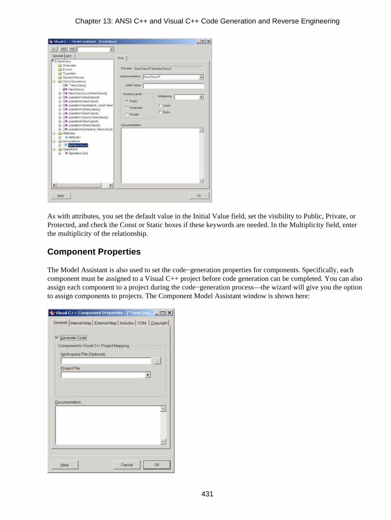
As with attributes, you set the default value in the Initial Value field, set the visibility to Public, Private, orProtected, and check the Const or Static boxes if these keywords are needed. In the Multiplicity field, enterthe multiplicity of the relationship.
Component Properties
The Model Assistant is also used to set the code−generation properties for components. Specifically, eachcomponent must be assigned to a Visual C++ project before code generation can be completed. You can alsoassign each component to a project during the code−generation process—the wizard will give you the optionto assign components to projects. The Component Model Assistant window is shown here:
Chapter 13: ANSI C++ and Visual C++ Code Generation and Reverse Engineering
431

To open the Model Assistant for a component, right−click the component and select Properties. On theGeneral tab, map the component to an existing Visual C++ project file. Optionally, you can set a Visual C++workspace file as well. If the file is an IDL file, set the IDL filename and path.
The Internal Map tab is used to set up the mapping of classes within the component to include statements. Foreach mapping, set the class (an asterisk [*] refers to all classes), include the filename, and include the filelocation. You can add as many mappings as needed.
The External Map tab is very similar, but is used to set up the include statements needed by classes in othercomponents to reference classes in this component.
On the Includes tab, you can set up includes statements to be generated in the header and body files for eachclass in the component. Add as many includes statements as you need, adding each on a separate line.
Use the COM tab to control how ATL objects will be generated for this component. The Update ATLArtifacts check box controls whether code is generated for ATL objects at all. If you do update the code,complete the rest of the settings on this screen to control how the code is updated:
• The Use Smart Pointers for Interface Associations check box will use the Visual C++ smart pointerfunctionality during code generation and reverse engineering.
• The Generate #Import Statements check box controls whether #import statements are created andwhere they are created.
• If there is a value in the Put #Import Statements In field, Rose will put all #import statements in thatfile.
•
Chapter 13: ANSI C++ and Visual C++ Code Generation and Reverse Engineering
432

If Include Full Path on Imports is checked, Rose will use the full path in the #import statement.
• If Use Default Attributes is checked and there is a value in that field, Rose will use the field valuewhen attributes are unspecified in the model.
Finally, you can use the Copyright tab to set copyright information for the component. Text you enter herewill be entered into the header and implementation files for the classes in that component.
Project Properties
Using the menu command Tools → Visual C++ → Properties, you can set properties that apply to the wholeRose model.
Table 13.7 lists each Visual C++ project property, its purpose, and the tab on the Visual C++ Propertieswindow you use to set the property.
Table 13.7: Visual C++ Project Properties
Property Purpose Tab
Generate Model IDs Controls whether Rose model IDs are inserted into thesource code.
Code Update
Generate DocumentationControls whether comments you entered into theDocumentation field of a class or other model elementare generated as comments in the source code.
Code Update
Generate #IncludeStatements
Controls whether #include statements are added to theheader file.
Code Update
Apply Pattern on Code Controls whether to apply the selections you made onCode Update
Chapter 13: ANSI C++ and Visual C++ Code Generation and Reverse Engineering
433

Generation the Operations and Accessors tabs to the generatedcode.
Generate DebugOperations for MFCClasses
Controls whether AssertValid and Dump operationsare created for MFC classes.
Code Update
Create Backup Files Controls whether backup files are created for sourcecode before Rose modifies them.
Code Update
Support CodeName Gives the user the option of naming an elementdifferently in the model and the source code.
Code Update
Reverse EngineerDocumentation
Pulls comments from the source code into theDocumentation field of the model element.
Model Update
Create OverviewDiagrams
Creates an overview diagram for reverse−engineeredcode.
Model Update
Update Model IDs inCode
Adds model IDs to the code during thereverse−engineering process.
Model Update
Default Package Sets the package in which reverse−engineeredelements are placed.
Model Update
Attribute Types Controls which types will be modeled as attributesrather than roles in reverse engineering.
Model Update
Containers Sets the container classes that can be used in theImplementation field for a role.
Containers
Class Operations Controls which operations will be generated for aclass.
Class Operations
Accessors Controls whether Get and Set operations are generatedfor an attribute or role.
Accessors
Visual C++ and ATL Objects
The Rose Visual C++ add−in includes support for ATL objects. If you are using ATL in your model, youshould first import the standard ATL classes. This step will help ensure that the round−trip engineeringprocess works properly. You can import ATL 3.0 classes into your model by selecting Tools → Visual C++→ Quick Import ATL 3.0. The ATL 3.0 classes will be imported into a package called ATL 3.0 in the Logicalview. Once the import is complete, you can create relationships between your classes and the ATL classes.
Converting an Existing Class to an ATL Object
You can create new ATL objects in Rose or simply convert existing classes in your Rose model to ATL.
To convert an existing class:
1. Right−click the class and select COM → New ATL Object.
2. You will see the ATL Object Properties window.
3. In the C++ section, enter the short name of the C++ class. The Class field will already be completedfor you.
4.
Chapter 13: ANSI C++ and Visual C++ Code Generation and Reverse Engineering
434

If the appropriate component already exists in the Rose model, select the C++ component and projectfor the C++ class. Otherwise, leave these fields blank.
5. In the COM section, enter the name of the CoClass and interface. When you press OK, Rose willcreate the CoClass and interface class and set their relationships.
6. If the appropriate component already exists in the Rose model, select the COM component andproject for the COM classes. Otherwise, leave these fields blank.
Note In Rose 2002, reverse−engineered MIDL components will be added to the model as components withthe <<MIDL>> stereotype. Any classes with a stereotype of <<coclass>> or <<interface>> will beautomatically mapped to the MIDL components.
Generated Code
In the following sections, we'll take a look at the C++ code generated for a class, an attribute, an operation,and for the different types of relationships between classes. In each of these sections, we'll include somesample code to give you an idea of what will be generated from your Rose model.
Rose uses the information in the specifications of the model elements when generating code. For example, itwill look at the different specifications for a class (visibility, attributes, operations, and so on) whengenerating code for the class.
Code Generated for Classes
Let's begin by looking at the code generated for a typical class. A class in your object model will become aC++ class when you generate code. Each class will generate code similar to the following:
Class TheClass{public:TheClass();~TheClass();};
However, a great deal of additional information will also be generated in the code. (We'll look at a completeheader and implementation file shortly.) All of the attributes, operations, and relationships of the class will bereflected in the generated code. The major elements generated for each class include:
• The class name
• The class visibility
• A constructor for the class (optional)
• A destructor for the class (optional)
•
Chapter 13: ANSI C++ and Visual C++ Code Generation and Reverse Engineering
435

Get() and Set() operations for each attribute (optional)
• Class documentation
• Attributes
• Operations
• Relationships
Each class in the model will generate two C++ files, a header file, and an implementation file. Each file willbe named using the class name. For example, an Employee class will generate an Employee.h file and anEmployee.cpp file.
When generating code with ANSI C++, Rose will use the package structure you established in the Componentview of your model to generate the appropriate directories. A directory will be created for each package in themodel. Within each of the directories Rose creates, there will be the .cpp and .h files for the classes in thatpackage. If you have not created components and packages in the Component view, Rose will use the packagestructure in the Logical view to create the directory structure.
Much of the information in your Rose model will be used directly when generating code. For example, theattributes, operations, relationships, and class name of each class will directly affect the code generated. Othermodel fields, such as the documentation entered for the class, will not directly affect the code. These fieldvalues are created as comments in the generated code.
Table 13.8 lists the fields available in the class specification window and notes which of these fields willdirectly affect the code generated.
Table 13.8: Effect of Class Specifications on Generated Code
Fields Effect on Code
Name Name in model will become class name
Type Directly affects the type of class created
Stereotype No effect
Export Control Directly affects the class visibility
Documentation Becomes a comment
Cardinality No effect
Space No effect
Persistence No effect
Concurrency No effect
Abstract Creates an abstract class
Formal Arguments Formal arguments are included in the code for a parameterized class
Operations Generated in code
Chapter 13: ANSI C++ and Visual C++ Code Generation and Reverse Engineering
436
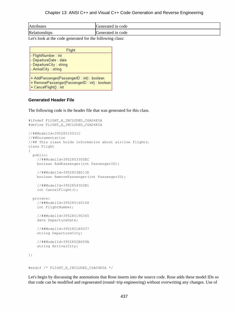
Attributes Generated in code
Relationships Generated in codeLet's look at the code generated for the following class:
Generated Header File
The following code is the header file that was generated for this class.
#ifndef FLIGHT_H_INCLUDED_C6AD4E5A#define FLIGHT_H_INCLUDED_C6AD4E5A
//##ModelId=39528510031C//##Documentation//## This class holds information about airline flights.class Flight{ public: //##ModelId=3952853300EC boolean AddPassenger(int PassengerID);
//##ModelId=3952853B013D boolean RemovePassenger(int PassengerID);
//##ModelId=3952854302B1 int CancelFlight();
private: //##ModelId=395285160108 int FlightNumber;
//##ModelId=395285190365 date DepartureDate;
//##ModelId=3952851E0037 string DepartureCity;
//##ModelId=3952852B009A string ArrivalCity;
};
#endif /* FLIGHT_H_INCLUDED_C6AD4E5A */
Let's begin by discussing the annotations that Rose inserts into the source code. Rose adds these model IDs sothat code can be modified and regenerated (round−trip engineering) without overwriting any changes. Use of
Chapter 13: ANSI C++ and Visual C++ Code Generation and Reverse Engineering
437

the model IDs is optional. To turn model IDs on or off, open the ANSI C++ component specification for thecomponent. On the Style tab, set model IDs to the Never Generate Model IDs option.
The generated file will include header information for the attributes and operations of the class. It can alsoinclude headers for a constructor, a destructor, a copy constructor, and other standard methods. To include anyof these, open the ANSI C++ Class Customization window and select the method(s) to generate. Or, if you areusing Visual C++, use the Model Assistant.
As you can see, Rose includes the visibility, parameters, parameter data types, and return type for eachoperation. Although Rose cannot code the operation itself, it does provide a "skeleton" framework for theprogrammers to use. You can generate code for the operation by adding default code in the operation'sInitialCodeBody property.
Generated Implementation File
The other file generated by Rose is an implementation file, with the default extension .cpp. The following isthe implementation file generated along with the header file we just examined.
#include "c:/Flight.h"
//##ModelId=3954129803B3boolean Flight::AddPassenger(int PassengerID){}
//##ModelId=395412A00093boolean Flight::RemovePassenger(int PassengerID){}
//##ModelId=395412A80121int Flight::CancelFlight(){}
Again, notice that Rose includes the operation visibility, parameters, parameter data types, and operationreturn type in the generated code. Had we selected the option to generate the constructor, destructor, or otherstandard methods (by right−clicking the class and selecting ANSI C++ Code Customization), these would be
Chapter 13: ANSI C++ and Visual C++ Code Generation and Reverse Engineering
438

included in the code as well. With Visual C++, use the Model Assistant to determine whether or not togenerate these methods.
Code Generated for Attributes
Aside from the class itself, Rose will generate the attributes for the class. For each attribute, Rose will include:
• Visibility
• Data type
• Default value
• Get operation (optional)
• Set operation (optional)
For a given attribute, Rose will generate code similar to the following:
Class TheClass{public:int PublicAttribute;int GetPublicAttribute();int GetProtectedAttribute();int GetPrivateAttribute();void set_PublicAttribute (int value);void set_ProtectedAttribute (int value);void set_PrivateAttribute (int value);
protected: int ProtectedAttribute;
private: int PrivateAttribute;
};
A great deal more, including comments and Rose identifiers, will be generated in a full header andimplementation file. Let's look in detail at the code generated for the following class:
Chapter 13: ANSI C++ and Visual C++ Code Generation and Reverse Engineering
439

In this example, we opened the ANSI C++ Class Customization window and selected the option to generateGet and Set methods for the FlightNumber attribute. Using Visual C++, you can use the Model Assistant tocontrol whether Get and Set methods are created. The header file now reads as follows:
#ifndef FLIGHTHINCLUDEDC6ABFE6A#define FLIGHTHINCLUDEDC6ABFE6A
//##ModelId=39541274036Bclass Flight{ public: //##ModelId=3954129803B3 boolean AddPassenger(int PassengerID);
//##ModelId=395412A00093 boolean RemovePassenger(int PassengerID);
//##ModelId=395412A80121 int CancelFlight();
//##ModelId=395413D80055 int get_FlightNumber() const;
//##ModelId=395413D800BA void set_FlightNumber(int left);
private: //##ModelId=3954127801F4 int FlightNumber;
//##ModelId=3954128202DF date DepartureDate;
//##ModelId=395412860122 string DepartureCity;
//##ModelId=3954128E0097 string ArrivalCity;
};
#endif /* FLIGHT_H_INCLUDED_C6ABFE6A */
Chapter 13: ANSI C++ and Visual C++ Code Generation and Reverse Engineering
440

The implementation file also includes the Get and Set methods. Note that Rose will include more than just themethod signature; it will actually code these methods for you. The implementation file for the Flight class isshown here:
#include "c:/Flight.h"
//##ModelId=3954129803B3boolean Flight::AddPassenger(int PassengerID){}
//##ModelId=395412A00093boolean Flight::RemovePassenger(int PassengerID){}
//##ModelId=395412A80121int Flight::CancelFlight(){}
//##ModelId=395413D80055int Flight::get_FlightNumber() const{ return FlightNumber;}
//##ModelId=395413D800BAvoid Flight::set_FlightNumber(int left){ FlightNumber = left;}
Code Generated for Operations
Rose generates code for each of the operations in the class. For each operation, the generated code includesthe operation name, the parameters, the parameter data types, and the return type. Each operation will generatecode similar to the following:
Class TheClass{public:void PublicOperation();
protected:void ProtectedOperation();
private:void PrivateOperation();};
We'll examine the code generated for the following class:
Chapter 13: ANSI C++ and Visual C++ Code Generation and Reverse Engineering
441

In the header file, Rose will generate the signatures for the operations:
#ifndef FLIGHT_H_INCLUDED_C6ABEA96#define FLIGHT_H_INCLUDED_C6ABEA96
//##ModelId=39541274036Bclass Flight{ public: //##ModelId=3954129803B3 boolean AddPassenger(int PassengerID);
//##ModelId=395412A00093 boolean RemovePassenger(int PassengerID);
//##ModelId=395412A80121 //##Documentation //## The CancelFlight operation will cancel all reservations for the //## flight, notify all passengers with reservations, and disable future //## reservations for the flight. int CancelFlight();
private: //##ModelId=3954127801F4 int FlightNumber;
//##ModelId=3954128202DF date DepartureDate;
//##ModelId=395412860122 string DepartureCity;
//##ModelId=3954128E0097 string ArrivalCity;
};
#endif /* FLIGHT_H_INCLUDED_C6ABEA96 */
As you can see, the full operation signature is generated in the code. Any documentation you entered for theoperation is also generated, as a comment in the code. If you enter information for the operation protocol,qualifications, exceptions, time, space, preconditions, semantics, or post−conditions, this information will notappear in the generated code.
Chapter 13: ANSI C++ and Visual C++ Code Generation and Reverse Engineering
442

Rose will also generate code for the operation in the implementation file. We just examined the header file forthe Flight class, so now let's take a look at the implementation file for this class.
#include "c:/Flight.h"
//##ModelId=3954129803B3boolean Flight::AddPassenger(int PassengerID){}
//##ModelId=395412A00093boolean Flight::RemovePassenger(int PassengerID){}
//##ModelId=395412A80121int Flight::CancelFlight(){}
As you can see, Rose includes each operation in the implementation file. Developers now need to go into theimplementation file and code each operation between the opening and closing braces.
Visual C++ Code Generation
For the most part, the code generated in Visual C++ is the same as that generated in ANSI C++, and followsthe rules described in the "Generated Code" section earlier in this chapter. Each class in the model becomes aclass in the Visual C++ project. Attributes become data members in Visual C++, and the data type, defaultvalue, access type, and other code−generation settings from Rose are directly translated into Visual C++.Operations create member functions in Visual C++. The code−generation add−in examines the operationvisibility, parameters, parameter data types, return type, and other code−generation properties to create themember function. Attributes are created for relationships, as described in the "Generated Code" section.
The differences between ANSI C++ and Visual C++ code generation lie in the components. Each componentin the Rose model will become either a Visual C++ project or an IDL file within a project. Classes areassigned to components during the code−generation process. Interfaces are generated in the IDL files, and arecreated using the process described earlier in the "Visual C++ and ATL Objects" section.
Reverse Engineering ANSI C++
To reverse engineer in ANSI C++, you must first select a component. All or some of the classes assigned tothat component can then be reverse engineered.
To reverse engineer one or more classes that are not in the Rose model at all:
1. Create a new component in the Component view.
2.
Chapter 13: ANSI C++ and Visual C++ Code Generation and Reverse Engineering
443

Open the ANSI C++ specification window for the new component.
3. In the Project Files area, click Add Files to browse the source file(s) you want to reverse engineer.
4. Click OK to close the ANSI C++ specification window.
5. Right−click the component and select ANSI C++ → Reverse Engineer.
6. Select the class(es) to reverse engineer and press OK.
7. The classes will be brought into the Rose model and added to the Logical view, under a packagenamed C++ Reverse Engineered.
Note To reverse engineer classes into a package other than C++ Reverse Engineered, open the C++specification window for the component and change the package name in the Reverse Engineering RootPackage field.
To reverse engineer a class that already exists in your model, right−click its component and select ANSI C++→ Reverse Engineer. Select the class(es) to reverse engineer and press OK. Alternately, you can right−clickthe class you want to reverse engineer and select ANSI C++ → Reverse Engineer.
When you reverse engineer a class, all of its attributes, operations, and relationships are reverse engineered aswell. The C++−to−Rose mapping we've discussed in the past several sections controls how the C++ code isrepresented in the Rose model.
Chapter 13: ANSI C++ and Visual C++ Code Generation and Reverse Engineering
444

Reverse Engineering Visual C++
You can reverse engineer a Visual C++ project into an existing component or into a new component in Rose.To begin either process, select Tools → Visual C++ → Update Model from Code. Rose will display a list ofexisting components in your Rose model.
To reverse engineer the project into a new component, right−click Visual C++ and select Add Component.Select the Visual C++ project to reverse engineer into the new component.
To reverse engineer the project into an existing component, right−click the appropriate component, selectProperties, and select the element(s) in the project that you wish to reverse engineer.
Click Next to show a summary, and then Finish to complete the reverse−engineering process. The elements inthe project will be mapped to Rose elements as we've discussed in this chapter.
Summary
In this chapter, we took a look at how various Rose model elements are implemented in C++. Using thecode−generation properties for classes, packages, attributes, operations, roles, and other model elements, youhave a great deal of control over what gets generated.
Again, the steps needed to generate ANSI C++ code are:
1. Create components.
2. Assign classes to components.
3. Set the code−generation properties.
4. Select a class or component to generate on a Class or Component diagram.
5. Select Tools → ANSI C++ → Class Customization.
6. Select Tools → ANSI C++ → Code Generation.
7. Select Tools → ANSI C++ → Browse Header or Browse Body to view the generated code.
The steps to generate Visual C++ code are:
1. Create component(s) corresponding to the project(s).
2.
Chapter 13: ANSI C++ and Visual C++ Code Generation and Reverse Engineering
445

Select Tools → Visual C++ → Model Assistant.
3. Select Tools → Visual C++ → Update Code.
4. Select the component(s) to update.
5. Set code−generation properties.
6. Select Finish to complete the process.
The steps needed to reverse engineer ANSI C++ code are:
1. Create a new component.
2. Use the ANSI C++ specification window to select the file(s) to reverse engineer.
3. Right−click the component and select ANSI C++ → Reverse Engineer.
4. Select the class(es) to reverse engineer and press OK.
The steps needed to reverse engineer Visual C++ code are:
1. Select Tools → Visual C++ → Update Model from Code.
2. Select an existing component to reverse engineer, or create a new component.
3. Select the project element(s) to reverse engineer.
In the next chapter, we'll examine the Java add−in for Rose. Using this powerful feature, you can model Javaclasses, interfaces, attributes, operations, relationships, JAR files, and WAR files. Through the new supportfor J2EE, you can now also model EJBs, servlets, and other constructs. The enhanced functionality in Rose2001, 2001A, and 2002 provide the ability to create a complete model of your Java application. The forward−and reverse−engineering features provide you with the ability to keep the code and the object modelconsistent.
Chapter 13: ANSI C++ and Visual C++ Code Generation and Reverse Engineering
446

Chapter 14: Java Code Generation and ReverseEngineering
Overview
In this chapter, we'll discuss how to generate Java code from your Rational Rose model and reverse engineer aRose model from your Java code. We'll discuss the code−generation properties that can be set for Java andtake a close look at how each Rose model element is implemented in the code. Then, we'll look at how toreverse engineer Java code and how to keep your model and code synchronized.
To generate code, you'll need to follow these steps:
1. Create the components (see Chapter 10, "Component View").
2. Assign classes to the components (see Chapter 10).
3. Set the code−generation properties.
4. Select a class or component to generate on a Class or Component diagram.
5. Select Tools → Java → Code Generation.
6. Select Tools → Java → Browse Java Source to view the generated code.
Rose will take a lot of information from the model to generate code. For example, it will look at themultiplicity, role names, containment, and other details of each relationship. It will look at the attributes,operations, visibility, and other details of each class. From all of the information you entered using thespecification windows for the various model elements, Rose will gather what it needs to generate code.
• Setting Java code−generation properties
• Generating Java code from your Rose model
• Mapping Rose elements to Java constructs
• Importing the Java Development Kit
• Reverse engineering Java into your Rose model
447
Introduction to Rose J
Rose J is the add−in to Rational Rose that supports the generation and reverse engineering of Java constructs.This feature includes:
• Integration with VisualAge Java and Visual J++
• Support for Java 2 Platform Enterprise Edition (J2EE) constructs
• Generation of Java code
• Reverse engineering Java constructs into a Rose model
• Support for Java frameworks, such as the Java™ Development Kit (JDK™) and Java™ FoundationClasses (JFC).
Let's begin with code generation. Rose J will examine the classes and components that you have created inyour Rose model and generate the appropriate source code for these components. There are a number ofcode−generation properties that will affect the generated source code. Using Rose J, Rose ID numbers willalso be created in the source code. These numbers help to keep the code from being overwritten duringround−trip engineering.
There is an auto−synchronization feature in Rose J, which automatically starts the code−generation processanytime a Java class has changed in the model. This feature will help ensure that the model and the sourcecode remain consistent.
Once you create your classes, components, attributes, operations, and other model elements, you can begin thecode−generation process. Before generating code, check the syntax of the model using the Tools → Java →Syntax Check menu option. If there are any problems, they will appear in the log window.
After you resolve any problems, you can set the code−generation properties and generate code. In this chapter,we will discuss in detail how to set the properties and how each Rose modeling element maps to a Javaconstruct. Table 14.1 lists the Java constructs and their corresponding model elements.
Table 14.1: Java−to−Rose Mapping
Java Construct Rose Element
Class Class
Variable Attribute
Method Operation
Interface Interface (class with stereotype of Interface)
.java file Component
Chapter 14: Java Code Generation and Reverse Engineering
448

Java package Component package
Java Bean Attribute
EJB (Enterprise Java Bean) Class
Servlet Class
Inner class Nested class
Implements relationship Realization relationship
Extends relationship Generalization relationship
Import statement Association, dependency, or generalization
Beginning a Java Project
When first creating a Java model, there are four steps you may want to follow. First, when working on aproject that will be primarily implemented in Java, you always want to set the default language to Java. This isdone through the Tools → Options menu. Click the Notation tab and set the default language to Java.
Next, select the framework you would like to use for your project. This is an optional step, but can provideyou with the foundation you need to model your application. We will discuss specific frameworks shortly.
Third, if you are using either Microsoft Visual J++ or IBM VisualAge for Java, you should enable the linksbetween Rose and these tools. Once you enable the links, you can generate code and reverse engineerVisualAge or Visual J++ projects directly from Rose.
Finally, be sure that the ClassPath environment variable is set. The ClassPath is used by Rose J to determinethe location of class libraries and other files while generating code and reverse engineering. To view theClassPath settings, select Tools → Java → Project Specification. The ClassPath entries will be displayed, andyou can add or remove entries using this dialog box.
Selecting a Java Framework
When you first create a Rational Rose model, you are given the option to base your model on an existingframework. Create a new Rose model, and you will see the window shown in Figure 14.1.
Figure 14.1: Rose frameworks
Note
Chapter 14: Java Code Generation and Reverse Engineering
449

If you do not see the frameworks window, select Add−Ins → Add−In Manager, and be sure FrameworkWizard is checked.
There are several Java frameworks available: J2EE, J2SE 1.2, J2SE 1.3, jdk−116, jdk−12, and jfc−11. (Thelast three are, respectively, Java Development Kit version 1.1.6, Java Development Kit version 1.2, and theJava Foundation Classes version 1.1.)
Simply select whichever framework you will be using for your project. Rose will automatically load classes,relationships, attributes, operations, and components from the selected framework into your new model. Youcan then use these elements as a foundation to create your own project.
Figure 14.2 is an example of a new Rose model using the J2EE framework. No new information has yet beenadded to the model. The figure shows only what is imported with the J2EE framework. Note that, forreadability, many of the packages in Figure 14.2 are not expanded; however, classes and other model elementsare inside each one.
Figure 14.2: Rose model with J2EE framework
You can also use a framework on an existing Rose model. To do so, you need to load the appropriatecontrolled units. Each package in the frameworks is stored as controlled units. Select File → Units → Load,and then navigate to the Rose 2000\framework\frameworks\shared components directory. The .cat files in thisdirectory are the controlled units for the frameworks. Each .cat file begins with the name of the framework,such as j2ee or j2se12, so you know which files to import for which framework. Select the .cat filesappropriate for your framework, and Rose will import them into your model.
Linking to IBM VisualAge for Java
Establishing a link between Rational Rose and IBM's VisualAge will allow you to update a VisualAge projectdirectly from within Rose or to reverse engineer a VisualAge project into Rose.
To set up the link between the two tools, first start VisualAge. Select File and then Quick Start. On the dialogbox, select Basic and then RoseLink Plug−In Toggle. This will establish the link from the VisualAge side.
To complete the process, start Rose. Select Tools → Java → Project Specification. On the Detail tab, set theVirtual Machine setting to IBM, as shown in Figure 14.3.
Chapter 14: Java Code Generation and Reverse Engineering
450

Figure 14.3: Java Virtual Machine setting
Select Tools → Java → IBM VisualAge for Java Project. Select the appropriate VisualAge project. The linkbetween the two tools is now set.
Linking to Microsoft Visual J++
Similar to the link with IBM's VisualAge, the link to Microsoft Visual J++ will allow you to generate codeand to reverse engineer using Rose and Visual J++. Once the link has been established, Rose can launchVisual J++ or Visual J++ can launch Rose in order to generate code or reverse engineer.
To set up the link to Visual J++, select Tools → Java → Project Specification. On the Detail tab, set theVirtual Machine setting to Microsoft.
You are now ready to work with Rose and Visual J++. From Rose, select Tools → Java → Generate Java tolaunch Visual J++ and generate code. From Visual J++, select the elements you wish to reverse engineer andselect Tools → Update Rose Model. Rose will be launched, and the elements will be reverse engineered intothe Rose model.
Java Code−Generation Properties
The Java code−generation properties can be set in two places. The defaults are set by using the Tools →Options menu item and then selecting the Java tab, as shown in Figure 14.4. You can set properties for thefollowing items:
• Attributes
• Classes
•
Chapter 14: Java Code Generation and Reverse Engineering
451

Module bodies
• Module specifications
• Operations
• Projects
• Roles
Figure 14.4: Java code−generation properties window
We'll discuss using these various properties throughout this chapter. We'll begin with a brief description of theavailable code−generation properties, then cover projects, modules, classes, attributes, operations, and roles.
Project Properties
The project properties affect all aspects of Java code generation in Rose. This section provides a listing of theproperties and their common settings.
The project properties are code−generation properties that apply more to the whole project than to anyspecific model element, such as a class or relationship. The options in this section include things like thedefault directory to use when generating code, the file extensions to use, and whether or not to stop generationif an error occurs. The project properties are listed in Table 14.2, along with their purposes and default value.(In this and subsequent code−generation property tables, we list the most commonly used properties.)
Table 14.2: Java Project Properties
Chapter 14: Java Code Generation and Reverse Engineering
452

Property Purpose Default
RootDir Directory to hold the Java project. <blank>
CreateMissingDirectories If True, creates any directories that arerequired if they do not exist.
True
StopOnError If True, Rose will stop code generation at thefirst error.
False
UsePrefixes If True, Rose will add user−defined prefixes tothe variable names.
False
AutoSync Automatically begins the code−generationprocess when a Java element changes in theRose model.
False
ShowCodeGenDlg Shows a progress dialog box while generatingcode.
False
JavadocDefaultAuthor Sets the value of the Javadoc @author tag.<blank>
JavadocDefaultVersion Sets the value of the Javadoc @version tag.<blank>
JavadocDefaultSince Sets the value of the Javadoc @since tag. <blank>
JavadocNumAsterisks Number of asterisks to use with the Javadoccomments.
0
MaxNumChars Maximum number of characters in a line ofgenerated Java code.
80
Editor Select the editor to use while browsing code.Rose's built−in editor
VM Select the version of the Java Virtual Machine(Sun, IBM, or Microsoft).
Sun
ClassPath Specifies the directory where code will begenerated.
<blank> (use currentdirectory)
InstanceVariablePrefix If UsePrefixes is True, then this prefix will beadded to all instance variables.
m_
ClassVariablePrefix If UsePrefixes is True, then this prefix will beadded to all class variables.
s_
DefaultAttributeDataType If no type is selected for an attribute, this typewill be used.
Integer
DefaultOperationReturnType If no return type is selected for an operation,this type will be used.
Void
NoClassCustomDlg Determines whether the custom specificationwindow will be suppressed for Java classesand other elements.
False
GlobalImports Sets import statements to be generated. Eachclass or package listed will generate an importstatement.
<blank>
OpenBraceClassStyle Sets whether an opening brace will start on anew line.
True
OpenBraceMethodStyle Sets whether an opening brace for a methodwill start on a new line.
True
UseTabs Determines whether to use tabs (as opposed tospaces) to indent the generated Java code.
False
Chapter 14: Java Code Generation and Reverse Engineering
453

UseSpaces Determines whether to use spaces (as opposedto tabs) to indent the generated Java code.
True
SpacingItems Number of tabs or spaces (depending on thevalues of UseTabs and UseSpaces) to use toindent the generated Java code.
3
RoseDefaultCommentStyle Use the default Rose comment style ingenerated code.
True
AsteriskCommentStyle Use asterisk comment style in generated code.False
JavaCommentStyle Use Javadoc tags for comments in generatedcode.
False
JavadocAuthor Controls whether the Javadoc @author tag isenabled.
True
JavadocSince Controls whether the Javadoc @since tag isenabled.
False
JavadocVersion Controls whether the Javadoc @version tag isenabled.
False
Most of these project properties can also be set in the Project Specification window. To open the ProjectSpecification window, select Tools → Java → Project Specification. On the Class Path tab, you can set theClassPath project property.
Figure 14.5 shows the Style tab of the Java Project Specification window. On this tab, you can set the valuesof the following properties:
• UseTabs
• UseSpaces
• SpacingItems (Number to Use)
• OpenBraceClassStyle (On New Line for Classes)
• OpenBraceMethodStyle (On New Line for Methods)
• RoseDefaultCommentStyle (Rose Default)
• AsteriskCommentStyle (Asterisk Style)
• JavaCommentStyle (Javadoc Style)
• MaxNumChars (Maximum Number of Characters in a Line)
•
Chapter 14: Java Code Generation and Reverse Engineering
454

JavadocAuthor, JavadocDefaultAuthor (@Author)
• JavadocVersion, JavadocDefaultVersion (@Version)
• JavadocSince, JavadocDefaultSince (@Since)
• JavadocNumAsterisks (Number of Asterisks)
Refer to Table 14.2 for a description of each of these properties.
Figure 14.5: Style tab of the Java Project Specification window
On the Detail tab of the Project Specification window, you can set additional project properties. Figure 14.6shows the Detail tab. It includes the following properties:
• Editor
• VM (Virtual Machine)
• RootDir (Root Directory)
• DefaultAttributeDataType (Attribute)
• DefaultOperationReturnType (Method Return)
•
Chapter 14: Java Code Generation and Reverse Engineering
455

UsePrefixes
• InstanceVariablePrefix
• ClassVariablePrefix
• StopOnError
• CreateMissingDirectories
• NoClassCustomDlg (Always Show Standard Specification Dialog for Classes)
• AutoSync (Automatic Synchronization Mode)
• ShowCodeGenDlg (Show Codegen Dialog)
Figure 14.6: Detail tab of the Java Project Specification window
Refer to Table 14.2 for a description of each of these properties.
Class Properties
In this section, we discuss the Java code−generation properties that apply to classes. These properties will letyou change the class name, decide whether or not constructors should be created for the class, and set otherclass−specific properties.
Chapter 14: Java Code Generation and Reverse Engineering
456

There are three places to set these properties. To set them for all classes, select Tools → Options, then clickthe Java tab and select Class from the drop−down list box. To set them for only one class, either select theJava tab on the standard class specification window and edit the properties there or open the custom Java classspecification window for the class.
Table 14.3 lists the Java class properties, their purposes, and their default values.
Table 14.3: Java Class Properties
Property Purpose Default
Final Includes the final modifier in the generated code. False
Static Declares that a nested Java class is static and that onlyone instance of the class can exist.
False
GenerateDefaultConstructor Controls whether or not a constructor willautomatically be generated for the class.
True
ConstructorIs Sets the visibility (public, private, protected) of theconstructor.
Public
GenerateFinalizer Includes a finalizer in the class. False
GenerateStaticInitializer Includes a static initializer in the class. False
GenerateInstanceInitializer Includes an instance initializer in the class. False
GenerateCode Generate code for the class. True
DisableAutoSync Disables the automatic generation of code when theclass changes. (Automatic generation is alwaysdisabled if the AutoSync project property is set toFalse.)
False
These properties can also be set using the custom Java specification window for the class, as shown in Figure14.7. As you can see on this window, you can set each of the class properties using the fields withcorresponding names. The ConstructorIs property is set through the Constructor Visibility field.
Figure 14.7: Setting class properties through the Java Class Specification window
Chapter 14: Java Code Generation and Reverse Engineering
457

In addition, you can mark the class as abstract using this window. An abstract class will never directly beinstantiated. You can mark the class as an interface, in which case the final modifier, finalizer, staticinitializer, and instance initializer will no longer be available. Using the Extends area, you can list any classesof which this is a subclass. Using the Implements area, you can list any interfaces that this class implements.
Attribute Properties
In this section, we cover the Java code−generation properties that relate to attributes. Using these properties,you can, for example, decide whether or not the attribute will be generated in the code.
There are three places to set these properties. To set them for all attributes, select Tools → Options, then clickthe Java tab and select Attribute from the drop−down list box. To set them for only one attribute, select theJava tab on the standard attribute specification window (right−click the attribute in the browser and selectOpen Standard Specification) or open the Java attribute specification window (right−click the attribute in thebrowser and select Open Specification) and edit the properties there. Figure 14.8 shows the Java tab underTools → Options, with which you can set properties for all attributes.
Figure 14.8: Setting Java attribute properties
Table 14.4 lists the attribute properties, their purposes, and their default values.
Table 14.4: Java Attribute Properties
Property Purpose Default
Final If True, includes a final modifier in the attribute. False
Transient Includes a transient modifier in the attribute. False
Volatile Includes a volatile modifier in the attribute. False
PropertyType Specifies the property type for a Java Bean. Not a Property
IndividualChangeMgt Specifies whether or not the Java Bean gets its ownregistration mechanism.
False
Chapter 14: Java Code Generation and Reverse Engineering
458

Read/Write Sets whether or not Rose will generate a Get and/or aSet method for the attribute.
Read & Write
GenerateFullyQualifiedTypes Include the complete file path in the generated codefor reference attributes.
False
You can set the values of these properties using the Java attribute specification window, as shown in Figure14.9.
Figure 14.9: Setting attribute properties through the Java Field Specification window
Using this window, you can also set the static flag, the attribute visibility, the initial value, and the data typefor the attribute. The static flag marks the attribute as a class variable as opposed to an instance variable. Theattribute visibility (public, private, protected, or package) controls what other classes will be able to access theattribute. The attribute's initial value is set using this window, and will be generated in the code. The data typecan be set by pressing the "…" button next to the Type field and selecting from the list of Java typespresented. The Container Class field is also displayed on this window, but is used only for relationships.
Operation Properties
Next, we discuss the Java code−generation properties that are specific to operations. These properties will letyou, for example, control whether the operation is abstract or not.
There are three places to set these properties. To set them for all operations, select Tools → Options, thenclick the Java tab and select Operation from the drop−down list box. To set them for only one operation,select the Java tab on the standard operation specification window, or open the Java operation specificationwindow and edit the properties there.
Table 14.5 lists the operation code−generation properties, their purposes, and their default values.
Table 14.5: Java Operation Properties
Property Purpose Default
Abstract Includes an abstract modifier in the operation. False
Static Includes a static modifier in the operation. False
Final Includes a final modifier in the operation. False
Chapter 14: Java Code Generation and Reverse Engineering
459

Native Includes a native modifier in the operation. False
Synchronized Includes a synchronized modifier in the operation.FalseAs with attributes, you can set the values of these properties using the Java specification window. Figure14.10 shows the Java specification window for an operation.
Using this window, you can also set the operation visibility (public, private, protected, or package), set theoperation return type, set the operation arguments, or list the exceptions that the operation will throw.
Figure 14.10: Setting operation properties through the Java Method Specification window
Module Properties
The module specification and body properties are those properties that are related to the files you willgenerate from Rose. These properties give you the ability to decide whether or not to include a copyrightnotice in the file and whether or not to list any configuration management strings to be generated in the code.
There are three places to set these properties. To set them for all files, select Tools → Options, then click theJava tab and select Module Specification or Module Body from the drop−down list box. To set them for onlyone file, select the Java tab on the standard component specification window or open the Java componentspecification window and edit the properties there.
Table 14.6 lists the code−generation properties for module specifications, their purposes, and their defaultvalues.
Table 14.6: Java Module Specification Properties
Property Purpose Default
CMIdentification Specifies a user−defined configuration managementidentification string.
<blank>
CopyrightNotice Specifies a user−defined copyright string to include inthe code as a comment.
<blank>
Using the Java Component Specification window, as shown in Figure 14.11, you can set these properties. Youcan also list any Java import statements you would like to include in the generated code.
Chapter 14: Java Code Generation and Reverse Engineering
460

Figure 14.11: Setting component properties through the Java Component Specification window
You can also set code−generation properties for a module body in Java. The available properties areCMIdentification and CopyrightNotice, as described in Table 14.6.
Role Properties
Role properties are the Java code−generation properties that affect the code generated for relationships. Usingthese properties, you can set the container class to be used for the attribute and change other specifics of thegenerated code for a role.
As with most of the other property sets, there are three places to set these properties. To set them for allrelationships, select Tools → Options, then click the Java tab and select Role from the drop−down list box. Toset them for a single relationship, open the relationship specification. On the Java tab of the relationshipspecification window, you can change the properties for that relationship.
Table 14.7 lists the role properties, their purposes, and their default values.
Table 14.7: Java Role Properties
Property Purpose Default
ContainerClass Specifies the container class to use if the relationship'smultiplicity is greater than one.
<blank>
InitialValue Specifies the default value for the attribute. <blank>
Final Includes a final modifier in the attribute. False
Transient Includes a transient modifier in the attribute. False
Volatile Includes a volatile modifier in the attribute. False
PropertyType Specifies the property type for a Java Bean. Not a Property
IndividualChangeMgt Specifies whether or not the Java Bean gets its ownregistration mechanism.
False
Read/Write (98i) Sets whether or not Rose will generate a Get and/or aSet method.
Read & Write
GenerateFullyQualifiedTypes False
Chapter 14: Java Code Generation and Reverse Engineering
461

Include the complete file path in the generated codefor reference attributes.
IsNavigable Indicates navigability True
Generating Code
Once you have created the classes, relationships, attributes, operations, EJBs, servlets, and other Javaelements in your Rose model, you can generate code. To generate code, follow these steps:
1. Create the needed components.
2. Assign the Java classes to the appropriate components.
3. Set the code−generation properties.
4. Select Tools → Check Model to check for language−independent model errors. Check the logwindow for any errors found, and resolve the errors.
5. Select Tools → Java → Syntax Check to check for Java−specific problems. Again, check the logwindow for a list of errors found, and resolve the errors.
6. Select the class(es) or component(s) to generate.
7. Select Tools → Java → Code Generation.
8. To view the generated code for a class, right−click the class on a diagram and select Java → BrowseJava Source.
Generated Code
In the following sections, we'll take a look at the Java code generated for a class, attribute, and operation, andfor the different types of relationships between classes. In each of these sections, we'll include some samplecode to give you an idea of what will be generated from your Rose model.
Rose uses the information in the specifications of the model elements when generating code. For example, itwill look at the different specifications for a class (visibility, attributes, operations, and so on) whengenerating code for the class.
Let's begin by looking at the code generated for a typical class.
Chapter 14: Java Code Generation and Reverse Engineering
462

Classes
A class in your object model will become a Java class when you generate code. All of the attributes,operations, and relationships of the class will be reflected in the generated code. The major elementsgenerated for each class include:
• The class name
• The class visibility
• A constructor for the class
• Class documentation
• Attributes
• Operations
• Relationships
Without a component mapping, each class in the model will generate one file with the .java extension. Eachfile will be named using the class name. For example, an Employee class will generate an Employee.java file.With a component mapping, the class (or classes) mapped to each component will be generated in a .java filefor the component.
Much of the information in your Rose model will be used directly when generating code. For example, theattributes, operations, relationships, and class name of each class will directly affect the code generated. Othermodel properties, such as the documentation entered for the class, will not directly affect the code. Theseproperties are created as comments in the generated code.
Table 14.8 lists the properties available in the class specification window and notes which properties willdirectly affect the code that is generated.
Table 14.8: Effect of Class Specifications on Generated Code
Property Effect on Code
Name Name in model will become class name.
Type Directly affects the type of class created.
Stereotype Directly affects the type of class created.
Export Control Directly affects the class visibility.
Documentation Appears as a comment.
Chapter 14: Java Code Generation and Reverse Engineering
463

Persistence Affects whether DDL can be generated for the class.
Abstract Creates an abstract class.
Formal Arguments Formal arguments are included in the code for a parameterized class.
Operations Generated in code.
Attributes Generated in code.
Relationships Generated in code.Let's look at the code generated for the following class:
The following code is the Java file that was generated for this class.
//Source file: C:\\Flight.java
/* Copyright Notice */
/**Comments for Flight Class*/public class Flight { private int FlightNumber;
public Flight() { }
/** @roseuid 394461CB01F3 */ public boolean AddPassenger(int PassengerID) { }}
Copyright Notice Section
The copyright notice section includes the following line of code:
/* Copyright Notice */
By default, there is no copyright notice generated for your code. If, however, you'd like to add a copyrightnotice to all files, you can change the code−generation properties. Select Tools → Options from the menu,then select the Java tab. Select Module Specification from the drop−down list box to display the modulespecification code−generation properties. Change the CopyrightNotice field to include any copyrightinformation. If information is entered, it will be generated.
You can override the default for a specific component by changing the value in the Copyright field in thecomponent specification window or in the CopyrightNotice property on the Java tab of the component's
Chapter 14: Java Code Generation and Reverse Engineering
464

standard specification window.
Attributes
Aside from the class itself, Rose will generate the attributes for the class. For each attribute, Rose will includeinformation about the attribute visibility, data type, and default value in the code. Let's look again at the codegenerated for the Flight class.
//Source file: C:\\Flight.java
/* Copyright Notice */
/**Comments for Flight Class*/public class Flight { private int FlightNumber;
public Flight() { }
/** @roseuid 394461CB01F3 */ public boolean AddPassenger(int PassengerID) { }}
As you can see, the code includes the attribute visibility and data type. If the default value is set, it will also beincluded in the generated code.
To apply one of the modifiers, such as the transient modifier, to an attribute, set the appropriate property toTrue. In this case, you set the transient property to True, and the attribute generates with the modifier, as in thefollowing code:
//Source file: C:\\Flight.java
/* Copyright Notice */
/**Comments for Flight Class*/public class Flight { private transient int FlightNumber;
public Flight() { }
/** @roseuid 394461CB01F3 */
Chapter 14: Java Code Generation and Reverse Engineering
465

public boolean AddPassenger(int PassengerID) { }}
The visibility options affect the generated attribute. In the above example, and as the default, attributes aregiven private visibility. If you set an attribute to Protected or Public, the following code is an example of whatyou will generate:
//Source file: C:\\Flight.java
/* Copyright Notice */
/**Comments for Flight Class*/public class Flight { private transient int FlightNumber; public long DepartureDate; protected int GateNumber;
public Flight() { }
/** @roseuid 394461CB01F3 */ public boolean AddPassenger(int PassengerID) { }}
Operations
Rose generates each of the operations in the class. For each operation, the generated code includes theoperation name, the parameters, the parameter data types, and the return type. Again, we'll examine the codegenerated for the Flight class:
//Source file: C:\\Flight.java
public class Flight { private int FlightNumber;
public Flight() {
Chapter 14: Java Code Generation and Reverse Engineering
466

}
/** @roseuid 39446D1B0084 */ public boolean AddPassenger(int PassengerID) { }
/** @roseuid 39446D230253 */ public boolean RemovePassenger(int PassengerID) { }
/** @roseuid 39446D2B02AE */ public boolean CancelFlight() { }}
As you can see, the full operation signature is generated in the code. Any documentation you enter for theoperation is also generated as a comment in the code.
Rose generates skeletal code for operations. That is, the operation signature is generated. Once you havegenerated the code, you insert the implementation code for each operation between the { and } delimiters ofthe operation. This protects the code during round−trip engineering.
You can enter exception information using the Java operation specification window, as shown here:
In the Throws field, select the appropriate Java exception class. When you generate code, the exceptioninformation will be generated as well:
//Source file: C:\\Flight.java
public class Flight
Chapter 14: Java Code Generation and Reverse Engineering
467

{ private int FlightNumber;
public Flight() { }
/** @roseuid 39446ECD011F */ public boolean AddPassenger(int PassengerID) throws java.lang.Exception { }
/** @roseuid 39446ED40101 */ public boolean RemovePassenger(int PassengerID) { }
/** @roseuid 39446EDB03BE */ public boolean CancelFlight() { }}
As with other model elements, you can control the code generated for an operation by modifying itscode−generation properties.
Bidirectional Associations
To support bidirectional associations, Rose will generate attributes in the code. Each of the classes in therelationship will contain an attribute to support the association. By default, Rose names the roles byappending "the" to the class name. Let's look at the code generated for the following relationship:
The following is the code for Passenger:
//Source file: C:\\Passenger.java
public class Passenger { private string FirstName; private string LastName; private string Address; private string City; private string State;
Chapter 14: Java Code Generation and Reverse Engineering
468

private long Zip; private string Phone; public FrequentFlyerAccount theFrequentFlyerAccount;
public Passenger() { }}
The following is the code for FrequentFlyerAccount:
//Source file: C:\\FrequentFlyerAccount.java
public class FrequentFlyerAccount { private int AccountID; private int NumberOfMiles; private string DateEstablished; public Passenger thePassenger;
public FrequentFlyerAccount() { }
/** @roseuid 394590F100A2 */ public boolean AddMiles(int Miles) { }
/** @roseuid 394590FE0209 */ public boolean UseMiles(int Miles) { }
/** @roseuid 394591060124 */ public int NewAccount() { }
/** @roseuid 39459113021D */ public boolean DeleteAccount(int AccountID) { }}
As you can see, Rose will automatically generate attributes on both sides of the bidirectional associationrelationship. With the FrequentFlyerAccount attribute, Passenger can access the public attributes andoperations of FrequentFlyerAccount. With the Passenger attribute, FrequentFlyerAccount can access thepublic attributes and operations of Passenger. If you want to use different names for the attributes instead ofthePassenger and theFrequentFlyerAccount, you can set role names for the association. These names will be
Chapter 14: Java Code Generation and Reverse Engineering
469

used instead, as in the following code for Passenger. In this example, we set the role names to MyAccount andAccountHolder.
//Source file: C:\\Passenger.java
public class Passenger { private string FirstName; private string LastName; private string Address; private string City; private string State; private long Zip; private string Phone; public FrequentFlyerAccount myAccount;
public Passenger() { }}
The following is the code for FrequentFlyerAccount:
//Source file: C:\\FrequentFlyerAccount.java
public class FrequentFlyerAccount { private int AccountID; private int NumberOfMiles; private string DateEstablished; public Passenger AccountHolder;
public FrequentFlyerAccount() { }
/** @roseuid 394590F100A2 */ public boolean AddMiles(int Miles) { }
/** @roseuid 394590FE0209 */ public boolean UseMiles(int Miles) { }
/** @roseuid 394591060124 */ public int NewAccount() { }
/**
Chapter 14: Java Code Generation and Reverse Engineering
470

@roseuid 39459113021D */ public boolean DeleteAccount(int AccountID) { }}
Rose will use the role name to generate the attribute name. By default, each generated attribute will havepublic visibility. To change the visibility, open the association specification window. Select either the Role AGeneral or Role B General tab, and change the Export Control property.
Note that this association has a multiplicity of one to one. See the upcoming sections titled "Associations witha Multiplicity of One to Many" or "Associations with a Multiplicity of Many to Many" for a discussion ofhow other multiplicity settings will affect code generation.
You can specify initial values for the generated attributes. Open the desired association's standardspecification, then select the Java A or Java B tab. Modify the InitialValue property to contain the initial valuefor the generated attribute.
Unidirectional Associations
As with bidirectional associations, Rose will generate attributes to support unidirectional associations. With aunidirectional association, however, an attribute is generated at only one end of the relationship. Let's look atthe Passenger and FrequentFlyerAccount classes again, but this time with a unidirectional relationship.
For these classes, code similar to the following code for Passenger would be created:
//Source file: C:\\Passenger.java
public class Passenger { private string FirstName; private string LastName; private string Address; private string City; private string State; private long Zip; private string Phone; public FrequentFlyerAccount theFrequentFlyerAccount;
public Passenger() { }}
This is the code for FrequentFlyerAccount:
//Source file: C:\\FrequentFlyerAccount.java
public class FrequentFlyerAccount { private int AccountID; private int NumberOfMiles;
Chapter 14: Java Code Generation and Reverse Engineering
471

private string DateEstablished;
public FrequentFlyerAccount() { }
/** @roseuid 394590F100A2 */ public boolean AddMiles(int Miles) { }
/** @roseuid 394590FE0209 */ public boolean UseMiles(int Miles) { }
/** @roseuid 394591060124 */ public int NewAccount() { }
/** @roseuid 39459113021D */ public boolean DeleteAccount(int AccountID) { }}
As you can see, Rose will generate an attribute for the relationship at only one end of the association.Specifically, it will generate an attribute in the client class, but not in the supplier class.
The code generated in the supplier class is the same as discussed in the previous section about bidirectionalassociations. With a bidirectional association, each class is given a new attribute, and the code discussed in theprevious section is included in both classes. With a unidirectional association, the code is included only in theclient class.
Again, note that the multiplicity here is one to one. Next let's take a look at how code is affected when themultiplicity settings are changed.
Associations with a Multiplicity of One to Many
In a one−to−one relationship, Rose can simply create the appropriate attributes to support the association.With a one−to−many relationship, however, one class must contain a set of the other class. Let's look at anexample.
Chapter 14: Java Code Generation and Reverse Engineering
472

In this case, we have a one−to−many relationship. Each flight has many tickets, but each ticket is for only oneflight. The code generated for this relationship is shown below in the code for Flight:
//Source file: C:\\Flight.java
public class Flight { private int FlightNumber; public Ticket theTicket[];
public Flight() { }
/** @roseuid 39446ECD011F */ public boolean AddPassenger(int PassengerID) { }
/** @roseuid 39446ED40101 */ public boolean RemovePassenger(int PassengerID) { }
/** @roseuid 39446EDB03BE */ public boolean CancelFlight() { }}
Following is the code for Ticket:
//Source file: C:\\Ticket.java
public class Ticket { private int SeatNumber; private long PurchasePrice; public Flight theFlight;
public Ticket() { }
/** @roseuid 3945946F0378 */ public int RefundTicket() { }}
Chapter 14: Java Code Generation and Reverse Engineering
473

In this example, Ticket simply contains an attribute of type Flight because the multiplicity states that there isone instance of Flight for each instance of Ticket. However, the multiplicity also states that there are manyinstances of Ticket for each instance of Flight. Therefore, an array of Ticket objects is created inside Flight.
If you don't want to use an array, you can change the code−generation properties to use a different containerclass. In either the Java tab of the standard association specification window or the Field tab of the Javaassociation specification window, set the ContainerClass code−generation property to the name of thecontainer class you'd rather use.
In the following example, we created a class called TicketList, which is a collection of Tickets. The followingcode is generated for the above association, but with the container class as type TicketList.
Code for Flight:
//Source file: C:\\Flight.java
public class Flight { private int FlightNumber; public TicketList theTicket;
public Flight() { }
/** @roseuid 39446ECD011F */ public boolean AddPassenger(int PassengerID) { }
/** @roseuid 39446ED40101 */ public boolean RemovePassenger(int PassengerID) { }
/** @roseuid 39446EDB03BE */ public boolean CancelFlight() { }}
Associations with a Multiplicity of Many to Many
The code generated here is similar to that created for a one−to−many relationship. With a many−to−manyrelationship, however, Rose will generate arrays on both ends of the relationship. Let's look at the codegenerated for the following relationship.
Chapter 14: Java Code Generation and Reverse Engineering
474

This is the code for Flight:
//Source file: C:\\Flight.java
public class Flight { private int FlightNumber; public Passenger thePassenger[];
public Flight() { }
/** @roseuid 39446ECD011F */ public boolean AddPassenger(int PassengerID) { }
/** @roseuid 39446ED40101 */ public boolean RemovePassenger(int PassengerID) { }
/** @roseuid 39446EDB03BE */ public boolean CancelFlight() { }}
This is the code for Passenger:
//Source file: C:\\Passenger.java
public class Passenger { private string FirstName; private string LastName; private string Address; private string City; private string State; private long Zip; private string Phone; public Flight theFlight[];
public Passenger()
Chapter 14: Java Code Generation and Reverse Engineering
475

{ }}
In this situation, arrays are created at both ends of the relationship. An array is used by default, but as wementioned earlier, you can change the container class that is used. To do so, use the relationship specificationwindow for the association. On the Java A or Java B tab, change the ContainerClass property to the name ofthe container class you wish to use.
To change the container class for all many−to−many association relationships, choose Tools → Options fromthe menu. On the Java tab, select Role from the drop−down list box. Change the value of the ContainerClasscode−generation property to the container class you wish to use.
Reflexive Associations
A reflexive association is treated much the same as an association between two classes. Let's look at the codegenerated for the following situation:
//Source file: C:\\EnginePart.java
public class EnginePart { public EnginePart theEnginePart[];
public EnginePart() { }}
As with a regular association, an attribute is created inside the class to support the relationship. If themultiplicity is one, a simple attribute is created. If the multiplicity is more than one, an array is created as anattribute, as above.
Aggregations
There are two types of aggregation relationships: by−value and by−reference. With a by−value relationship,one class contains another. With a by−reference relationship, one class contains a reference to another. Codegenerated for either type of aggregation in Java is the same.
Here we have an aggregation relationship between a flight schedule and the flights on the schedule. Eachschedule contains one or more flights, and each flight can be on zero or more schedules.
Chapter 14: Java Code Generation and Reverse Engineering
476

The code that is generated shows a Flight attribute inside Schedule. Because the multiplicity of therelationship is one or more, there is an array of Flights inside Schedule.
The following is the code for the Schedule class:
//Source file: C:\\Schedule.java
public class Schedule { private date BeginDate; private date EndDate; public Flight theFlight[];
public Schedule() { }}
The following is the code for the Flight class:
//Source file: C:\\Flight.javapublic class Flight { private int FlightNumber; private date FlightDate;
public Flight() { }
/** @roseuid 39446ECD011F */ public boolean AddPassenger(int PassengerID) { }
/** @roseuid 39446ED40101 */ public boolean RemovePassenger(int PassengerID) { }
/** @roseuid 39446EDB03BE */ public boolean CancelFlight() { }}
Chapter 14: Java Code Generation and Reverse Engineering
477
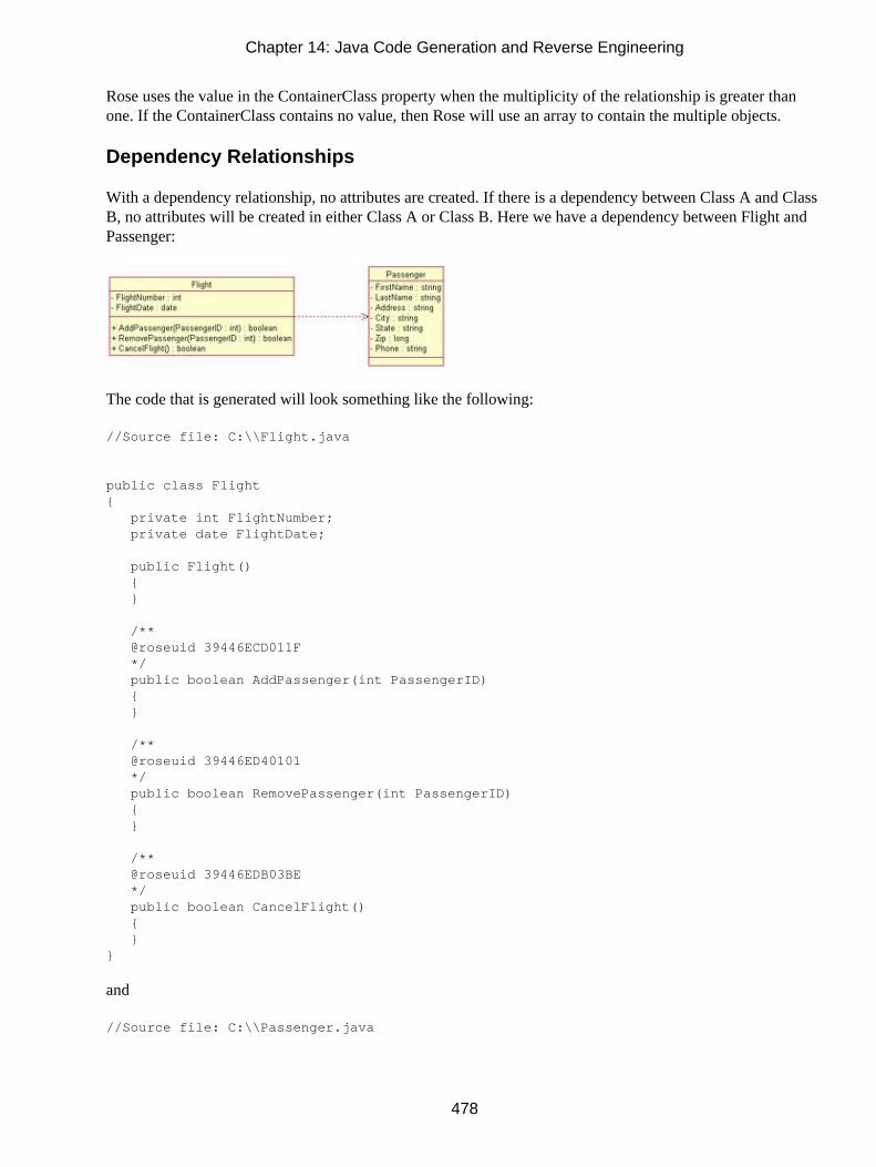
Rose uses the value in the ContainerClass property when the multiplicity of the relationship is greater thanone. If the ContainerClass contains no value, then Rose will use an array to contain the multiple objects.
Dependency Relationships
With a dependency relationship, no attributes are created. If there is a dependency between Class A and ClassB, no attributes will be created in either Class A or Class B. Here we have a dependency between Flight andPassenger:
The code that is generated will look something like the following:
//Source file: C:\\Flight.java
public class Flight { private int FlightNumber; private date FlightDate;
public Flight() { }
/** @roseuid 39446ECD011F */ public boolean AddPassenger(int PassengerID) { }
/** @roseuid 39446ED40101 */ public boolean RemovePassenger(int PassengerID) { }
/** @roseuid 39446EDB03BE */ public boolean CancelFlight() { }}
and
//Source file: C:\\Passenger.java
Chapter 14: Java Code Generation and Reverse Engineering
478

public class Passenger { private string FirstName; private string LastName; private string Address; private string City; private string State; private long Zip; private string Phone;
public Passenger() { }}
Rose will place no references to Flight inside Passenger or Passenger inside Flight. The dependencyrelationship does not generate any code for the relationship.
Generalization Relationships
A generalization relationship in UML becomes an inheritance relationship in Java. In your Rose model, aninheritance relationship is shown as follows:
For this type of relationship, Rose will generate something that looks like this:
//Source file: Parent.java
//Source file: C:\\Parent.java
public class Parent {
public Parent() { }}
and
//Source file: C:\\Child.java
public class Child extends Parent {
Chapter 14: Java Code Generation and Reverse Engineering
479

public Child() { }}
In the code for the parent class, there is no mention of the child class. This helps keep the parent generic;many classes can inherit from it without affecting its code. In the child class, the code is generated to supportits inheritance from the parent class. The class declaration will look like this:
Public class Child extends Parent
Interfaces
In Rose, a Java interface is modeled as a class with a stereotype of Interface. It contains operation signatures,but does not contain any implementation for the operations. The implementation of the operations is containedin other classes. The interface is connected with a realization relationship to the class(es) that implement theinterface:
When you generate code, Rose will generate a Java interface. The code for the interface and implementationclasses from the example above is shown here:
This is the code for the interface class:
//Source file: C:\\Interface.java
public interface Interface {
/** @roseuid 3945AB7201CA */ public void DoSomething();}
and for the implementation class:
//Source file: C:\\Class.java
public class Class implements Interface {
public Class() { }
Chapter 14: Java Code Generation and Reverse Engineering
480

/** @roseuid 3945AC1B032C */ public void DoSomething() { }}
As you can see, Rose places the "implements" keyword in the implementation class to set the interface for thatclass. Once the code has been generated, you can program the DoSomething() operation in theimplementation class.
Java Beans
You can model a Java Bean in Rose as an attribute. The attribute will have all of the standard specificationsavailable in Rose, with three additional fields: the type of bean (Bound, Constrained, Simple, or Not a Bean);a Read/Write field, which controls the Get and Set operations generated; and a flag for change management.Figure 14.12 shows the Java attribute specification window, in which you can set these three properties.
Figure 14.12: Setting Java Bean properties
The Read/Write field controls whether a bean Get and/or bean Set operation will be generated. The Read &Write option will create both a Get and a Set operation. Read will create only a Get operation, and Write willcreate only a Set operation.
There are three types of beans available. A simple bean creates just a Get and Set method, depending on thevalue of the Read/Write field. In the above example, the code will look like this:
//Source file: C:\\SampleClass.java
public class SampleClass { private int SampleBean;
public SampleClass() { }
Chapter 14: Java Code Generation and Reverse Engineering
481

/*** Access method for the SampleBean property.** @return the current value of the SampleBean property @roseuid */ public int getSampleBean() { return SampleBean; }
/*** Sets the value of the SampleBean property.** @param aSampleBean the new value of the SampleBean property @roseuid */ public void setSampleBean(int aSampleBean) { SampleBean = aSampleBean; }}
With a bound bean, Rose will include an import java.beans.* statement in the generated code. In addition, itwill generate a declaration, a Set operation, an optional Get operation (depending on the value of theRead/Write field), a PropertyChangeSupport attribute, an addPropertyChange−Listener operation, and aremovePropertyChangeListener operation. The code will now look like this:
//Source file: C:\\SampleClass.java
import java.beans.*;public class SampleClass { private int SampleBean;
/*** common PropertyChangeSupport instance */ protected PropertyChangeSupport commonPCS = new PropertyChangeSupport(this);
public SampleClass() { }
/*** Access method for the SampleBean property.** @return the current value of the SampleBean property @roseuid */ public int getSampleBean() { return SampleBean; }
/*** Sets the value of the SampleBean property.** @param aSampleBean the new value of the SampleBean property
Chapter 14: Java Code Generation and Reverse Engineering
482
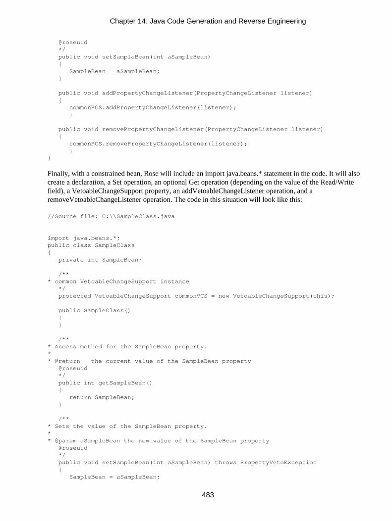
@roseuid */ public void setSampleBean(int aSampleBean) { SampleBean = aSampleBean; }
public void addPropertyChangeListener(PropertyChangeListener listener) { commonPCS.addPropertyChangeListener(listener); }
public void removePropertyChangeListener(PropertyChangeListener listener) { commonPCS.removePropertyChangeListener(listener); }}
Finally, with a constrained bean, Rose will include an import java.beans.* statement in the code. It will alsocreate a declaration, a Set operation, an optional Get operation (depending on the value of the Read/Writefield), a VetoableChangeSupport property, an addVetoableChangeListener operation, and aremoveVetoableChangeListener operation. The code in this situation will look like this:
//Source file: C:\\SampleClass.java
import java.beans.*;public class SampleClass { private int SampleBean;
/*** common VetoableChangeSupport instance */ protected VetoableChangeSupport commonVCS = new VetoableChangeSupport(this);
public SampleClass() { }
/*** Access method for the SampleBean property.** @return the current value of the SampleBean property @roseuid */ public int getSampleBean() { return SampleBean; }
/*** Sets the value of the SampleBean property.** @param aSampleBean the new value of the SampleBean property @roseuid */ public void setSampleBean(int aSampleBean) throws PropertyVetoException { SampleBean = aSampleBean;
Chapter 14: Java Code Generation and Reverse Engineering
483

}
public void addVetoableChangeListener(VetoableChangeListener listener) { commonVCS.addVetoableChangeListener(listener); }
public void removeVetoableChangeListener(VetoableChangeListener listener) { commonVCS.removeVetoableChangeListener(listener); }}/* SampleClass.removePropertyChangeListener(PropertyChangeListener){ commonPCS.removePropertyChangeListener(listener); } *//* SampleClass.addPropertyChangeListener(PropertyChangeListener){ commonPCS.addPropertyChangeListener(listener); } */
Support for J2EE
The J2EE standard is a method for developing complex distributed applications without needing to focus onthe details of transaction processing, database connectivity, or security. Instead, J2EE allows the developers tofocus on the unique business logic of the application. J2EE elements—including EJBs, servlets, JAR files, andWAR files—are now supported in Rational Rose. In this section, we'll explore how to create each of thesefour types of elements in Rose.
EJBs
An Enterprise Java Bean, or EJB, is modeled in Rose as a class with an EJB stereotype. Depending upon thebean type (Entity or Session), the class will have a stereotype of EJBEntity or EJBSession. An entity EJB willhave relationships to three other elements: the home interface, the remote interface, and the primary key. Eachof these three is modeled in Rose as a class with stereotypes EJBHome−Interface, EJBRemoteInterface, andEJBPrimaryKey, respectively. Figure 14.13 shows an example of an entity EJB.
Figure 14.13: Entity EJB
Chapter 14: Java Code Generation and Reverse Engineering
484

With a session EJB, the class will have relationships to two other classes: the home interface and the remoteinterface. These classes have stereotypes of EJBHomeInterface and EJBRemoteInterface, respectively.
To create an EJB, select Tools → Java → J2EE → New EJB. Using the window shown in Figure 14.14, enterthe type of EJB (Entity or Session), the name of the home interface, the name of the remote interface, and thename of the EJB.
Figure 14.14: Setting EJB properties
If this is an entity bean, use the Bean−Managed or Container−Managed radio buttons to control whether thebean's persistence is managed by the container or within the bean itself.
If the bean is a session bean, use the Stateless or Stateful radio buttons to control whether the client maintainsthe bean's state between method calls.
If this is an entity EJB, select the Persistence Properties option in the treeview on the left side of the windowin Figure 14.14. The Persistence Properties window is shown in Figure 14.15. Using this window, you can setitems such as the name of the primary key class and the ejbFinder's method, name, parameter, and parametertype.
Figure 14.15: Setting Persistence properties
You can enter the name of the primary key in the Primary Key Class Name field, or check the Match Patterncheck box. If Match Pattern is checked, the name of the primary key will be the bean name followed by theletters "PK."
Chapter 14: Java Code Generation and Reverse Engineering
485

In the Class Methods field, checking the hashcode(), equals(), or toString() check box(es) will cause Rose togenerate the selected method(s) in the code.
In the ejbFind<Method> field, you enter the name of an ejbFinder method to create. In the Parameter Namefield, enter the parameter(s) for the method. If there are multiple parameters, separate them with commas. Inthe Parameter Type field, enter the data type for each parameter. Enter the types, separated by commas, in theorder in which the parameters are listed.
Select the Deployment Descriptor option in the treeview on the left side of the window to view theDeployment Descriptor window, as shown in Figure 14.16. Once these properties are set, Rose can generatethe appropriate XML documents for the descriptor.
Figure 14.16: Setting Deployment Descriptor properties
You have the option to enter a value in the Enterprise Bean's Name field. If you enter a name, this is the namethat will be used in the .jar file. If not, Rose will use the implementation bean's name.
Next, check the Is Re−entrant box if more than one client will be able to access the bean's methods.
In the Deployment Descriptor Structural Information area, select one of the following from the drop−downlist box:
• Cmp−field for a container−managed persistence entry
• Env−entry for a environment variable entry
• Resource−ref for a resource manager reference entry
• Ejb−ref for a reference to the home or remote interface of another EJB
• Security−role−ref for a security role reference entry
Then, enter the name, value, and type for the entry. For an ejb−ref entry, specify the home and remote
Chapter 14: Java Code Generation and Reverse Engineering
486

interfaces. Click the Add button to add the entry to the list, and create other entries as needed.
Servlets
Like an EJB, a servlet is modeled in Rose as a class with a special stereotype. In this case, the stereotype isHttpServlet. Using the servlet properties dialog boxes we will discuss in this section, you can control whatmethods and other properties are created for the servlet.
To create a new servlet, select Tools → Java → J2EE → New Servlet. You will see the J2EE ServletSpecification window, as shown in Figure 14.17.
Figure 14.17: Servlet Specification window
First, enter the name of the servlet. Then, check IsSingleThread if one thread of the servlet instance willexecute at a time. Check HttpServlet or GenericServlet if the servlet extends either of these. In the DispatcherPath field, enter the path to another servlet that will be used to receive requests or send requests to the currentservlet. In the Operations area, check the method(s) that you would like Rose to generate for the servlet.
Select the Advanced Properties option on the left side of the window to display the Advanced Propertieswindow, as shown in Figure 14.18.
Figure 14.18: Servlet Advanced Properties window
Select the Context Object check box to create a servlet context object. In the The Request section of thescreen, select the method(s) the servlet will use to retrieve requests. In the Servlet Content Type field, enterthe type that the servlet will use to respond to a client.
Chapter 14: Java Code Generation and Reverse Engineering
487

Select the Deployment Descriptor option on the left side of the window to display the deployment descriptoroptions for the servlet, as shown in Figure 14.19. These parameters will be used to create the WAR file for theservlet.
Figure 14.19: Servlet Deployment Descriptor window
First, enter a descriptive name for the servlet in the Display Name field. Then, enter the security role(s) andthe name and value of a context parameter, if any. Next, list the welcome files to include, enter the initparameter name and value, provide a session timeout value, and choose whether or not the servlet isdistributable.
JAR and WAR Files
Java Archive (JAR) and Web Archive (WAR) files are used as containers for EJBs and servlets, respectively.To create a JAR file, select Tools → Java → J2EE → New ejb−JAR file. To create a WAR file, select Tools→ Java → J2EE → New WAR file. The JAR or WAR specification window will appear. The JARspecification window is shown in Figure 14.20.
Figure 14.20: JAR Specification window
In the Java Archive Tool field, select the executable that will be used to create the JAR (if you are creating aWAR, select the executable that will be used to create the WAR). Enter the JAR or WAR name in the Namefield. In the Java Class File(s) field, select the class(es) to include in the JAR or WAR. Finally, in the XMLDeployment Descriptor(s) field, select the XML deployment descriptors to include.
Chapter 14: Java Code Generation and Reverse Engineering
488

Automated J2EE Deployment
In Rose 2001A, you can generate source code for Java classes. Deployment occurs manually after thegeneration. Rose 2002 automates the deployment of Java classes to WebLogic, WebSphere, and SunReference implementations. Follow the steps below to deploy Java classes.
1. Start the J2EE Deployment Wizard by selecting Tools → J2EE Deploy → Deploy from the menu.
2. Select the deployment target from the following list:
WebLogic 5.1
WebLogic 6.0
WebLogic 6.1
WebSphere 3.5
Web Server (J2EE 1.2)
3. Select the working directory where temporary files will be stored.
4. Select the directory for the Java class files.
5. Check Edit XML Deployment Descriptors to customize XML deployment descriptor files prior todeployment.
Rose will display a Properties window for the selected deployment target. Specific information on theProperties window is dependent on the deployment target.
6. Specify the property values, and then click Next.
7. Rose will display a window prompting for the model elements to deploy.
8. Select the model elements to deploy, and then click Next. Deployments to WebLogic and WebSpherecan deploy EJBs and Java classes. Deployments to WebApplication can deploy web files, servlets,and Java classes.
Rose will display a summary screen.
9. Review and make changes as needed prior to deployment.
Chapter 14: Java Code Generation and Reverse Engineering
489

If the Edit XML Deployment Descriptors check box is checked, Rose will display an editor, whichcan be used to edit the XML deployment descriptors.
10. Click Save All to begin the deployment process.
When Rose is finished, a summary screen will be displayed.
Reverse Engineering
When you reverse engineer Java code, Rose will read the classes, relationships, attributes, and operationsfrom the code and generate the appropriate model elements.
In this section, we'll go through each of the steps needed to reverse engineer Java code. The information inyour code will be imported directly into the Rose model that is currently open.
1. If you are using J2EE, JFC, or another Java foundation, create a new model and select the appropriateframework.
2. Select Tools → Java → Reverse Engineer Java. Rose will display the Java Reverse Engineer window,as shown in Figure 14.21. Using this window, you can select the files you want to reverse engineer.
If you instead see a message that the ClassPath environment variable is not set, there is another stepthat you must take first. Create an environment variable called ClassPath, and set this variable to thedirectory or directories where the Java class files are stored.
Figure 14.21: Java Reverse Engineer window
3. From the directory tree structure, select the directory that contains the files you want to reverseengineer. As you change directories, the available files will appear in the list box in the upper−right
Chapter 14: Java Code Generation and Reverse Engineering
490

area of the window, as we saw in Figure 14.21.
4. Select the files you wish to reverse engineer and press Add. The files will now appear in the lowersection of the window.
5. Once all needed files have been added to the bottom section of the window, click to select the filesyou wish to reverse engineer (or press the Select All button to reverse engineer them all) and thenclick the Reverse button. If there are any errors, they will be written to the log window.
You can reverse engineer .java files, .class files, .jar files, or .cab files. When Rose reverse engineers Javacode, it places the new classes in the browser, but does not include them on any Class diagrams.
Java constructs are reverse engineered using the mapping discussed throughout this chapter. For example,interfaces are modeled as classes with a stereotype of Interface. Here, we will briefly review the mapping forreverse engineering.
Rose will look for classes in the source code, and will reverse engineer the attributes and operations of eachclass. For each operation, the operation code itself will not be included in the model, but the operationsignature, including the parameters and return type, will be. Rose will also look for and model any "static,""final," "abstract," "native," or "synchronized" keywords for the operation. Finally, Rose will model thevisibility of the operation as public, private, protected, or package.
Rose will also look for interfaces, and will reverse engineer them as classes with an Interface stereotype. Itwill establish a realize relationship between the implementation class and the interface.
If an attribute is a primitive data type, such as an integer or string, Rose will simply model it as an attribute ofthe reverse−engineered class. If, however, the attribute's type is another class in the Rose model, Rose willmodel it as a relationship between the two classes. For example, if the Flight class has an attribute calledPassengerName, which has a type of Passenger, Rose will create an association between Flight and Passengerwith a role called PassengerName.
For each attribute, Rose will examine any initial value, the attribute visibility (public, private, protected, orpackage), and any "static," "final," "volatile," or "transient" keywords for the attribute.
Summary
In this chapter, we took a look at how various Rose model elements are implemented in Java. Using thecode−generation properties for classes, packages, attributes, operations, associations, aggregations, and othermodel elements, you have a great deal of control over what gets generated.
We examined the steps needed to generate code from a Rose model, and to reverse engineer Java code into aRose model. Again, these are the steps you need to follow to generate code:
1. Create components.
2.
Chapter 14: Java Code Generation and Reverse Engineering
491

Assign Java classes to components.
3. Set code−generation properties.
4. Select Tools → Check Model.
5. Select Tools → Java → Syntax Check.
6. Select the class(es) or component(s) to generate.
7. Select Tools → Java → Code Generation.
The steps you'll need to reverse engineer Java code are:
1. Load the appropriate framework.
2. Select Tools → Java → Reverse Engineer Java.
3. Select the file(s) to reverse engineer, and press Reverse.
In the next chapter, we'll take a look at code generation and reverse engineering with Rose and Visual Basic.The Visual Basic add−in includes standard VB constructs such as class modules, forms, interfaces, and ADOobjects. The wizard−driven user interface provides a quick and easy way to set your code−generationproperties, generate VB code, and reverse engineer VB code. All of these features can help you build robustapplications that stay consistent with the object model.
Chapter 14: Java Code Generation and Reverse Engineering
492

Chapter 15: Visual Basic Code Generation andReverse EngineeringIn this chapter, we discuss how to generate Visual Basic code from your Rational Rose model and how toreverse engineer Visual Basic code into a Rose model.
To generate code, you will need to follow these steps:
1. Create components (see Chapter 10, "Component View").
2. Assign classes to components (see Chapter 10).
3. Set the code−generation properties.
4. Select a class or component to generate on a Class or Component diagram.
5. Select Tools → Visual Basic → Update Code to begin the Code−Generation Wizard.
6. Select Tools → Visual Basic → Browse Visual Basic Source to view the generated code.
We'll discuss the code−generation properties that can be set, and take a close look at how each Rose modelelement is implemented in the code.
Rose will use a lot of information in the model to generate code. For example, it will look at the multiplicity,role names, containment, and other details of each relationship. It will look at the attributes, operations,visibility, and other details of each class. From all of the information you enter using the specificationwindows for the various model elements, Rose will gather what it needs to generate code.
To reverse engineer code, you will need to follow these steps:
1. Create a component and assign a Visual Basic project to the component.
2. Select Tools → Visual Basic → Update Model from Code.
3. Select the component(s) and class(es) to update.
4. Select Finish to complete the process.
♦
493

Setting Visual Basic code−generation properties
♦ Generating Visual Basic code from your Rose model
♦ Mapping Rose elements to Visual Basic constructs
♦ Reverse engineering Visual Basic code into a Rose model
Starting a Visual Basic Project
Rather than start from scratch, you may want to import the standard Visual Basic classes into your Rosemodel. By doing so, you will have access to all of the standard classes and interfaces, and you can set up theappropriate relationships between your classes and the standard Visual Basic classes. This, in turn, will help inthe code−generation and reverse−engineering processes.
Begin by creating a new Rose model. When the Framework Wizard appears, select Visual Basic Standard.The Visual Basic framework will be loaded, and the classes will show under the stdole Ver 2.0, VB Ver 6.0,VBA Ver 6.0, and VBRUN Ver 6.0 packages in the Logical view. Your Rose model will look like Figure15.1.
Figure 15.1: Visual Basic framework
Each of these four packages contains a set of standard classes, interfaces, and relationships. Each packagecontains an overview diagram that presents the elements in the package and the relationships between them.You can familiarize yourself with the model elements in the packages and then set up the needed relationshipsbetween your classes and the standard ones.
Visual Basic Code−Generation Properties
Visual Basic code generation using Rational Rose is extremely flexible. You have full control over what getsgenerated and many of the details of how the generated code will look. For example, for each class, you can
Chapter 15: Visual Basic Code Generation and Reverse Engineering
494

decide if initialization and termination routines will automatically be created. For each attribute, you controlthe visibility, name, and whether Get and Set operations should automatically be created. For each module,you control the filename. For each generalization, you control if the implements delegation is used.
All of these things are controlled through the code−generation properties. Rose provides property sets thatdeal with classes, attributes, operations, module specifications, associations, and generalizations.
You can see all of these properties by selecting Tools → Options, then selecting the Visual Basic tab.
Anything you change using this window will set the default for all classes, attributes, operations, and so on.
You can also set the code−generation properties for a single class, attribute, operation, or other modelelement. To do so, open the specification window for the model element and select the Visual Basic tab. Onthis tab, you can change the properties that apply to that particular type of model element.
Finally, you can set the properties using the Visual Basic Model Assistant. The Model Assistant is a visualtool used to provide detailed information for a class or other model element. These details are then used in thecode−generation and reverse−engineering processes.
In the following sections, we'll examine the code−generation properties for classes, operations, attributes, andmodules. We'll look at how to set the properties using the specification window or the Model Assistant.
Class Properties
Class properties are the Visual Basic code−generation properties that apply to classes. These properties willlet you change the class name and set other class−specific properties.
Chapter 15: Visual Basic Code Generation and Reverse Engineering
495

There are three places to set these properties. To set them for all classes, select Tools → Options, then clickthe Visual Basic tab and select Class from the drop−down list box. To set them for only one class, select theVisual Basic tab on the class specification window and edit the properties there, or use the Model Assistant.
Table 15.1 lists the Visual Basic class properties, their purposes, and their default values.
Table 15.1: Class Code−Generation Properties
Property Purpose Default
Update Code Specifies if code can be updated for the class True
Update Model Specifies if the model can be updated for the class True
OptionBase Sets the base identifier for arrays (usually 0 or 1) <blank>
OptionExplicit Controls whether variable names must be explicitly declaredTrue
OptionCompare Controls the method by which string comparisons are made <blank>
Instancing Determines how classes are exposed to other applications MultiUseMany of these class properties can be set using the Model Assistant. To open the Model Assistant, right−clickthe class and select Model Assistant. The window shown in Figure 15.2 will be displayed.
Chapter 15: Visual Basic Code Generation and Reverse Engineering
496

Figure 15.2: Using the Model Assistant's Class tab to set class properties
The Should Be Generated field corresponds to the Update Code property and determines whether the classwill be reflected in the generated code. The Should Be Updated from Code field corresponds to the UpdateModel property, and the Instancing field corresponds to the Instancing property.
In addition to these fields, you can set the following information using this screen:
• The Abstract Interface field sets the class as abstract. No method bodies will be created for this class.
• The Stereotype field sets the type of class (class module, interface, form, collection, module, etc.).Select one of the standard Visual Basic stereotypes from the drop−down list box. The stereotype youselect controls what type of class Rose will generate in Visual Basic.
• The Collection Class field is used to create a new, user−defined collection class. Rose will create thecollection class and set up a dependency between the collection class and the current class:
Chapter 15: Visual Basic Code Generation and Reverse Engineering
497

The Option Base, Option Explicit, and Option Compare properties can be set using the Options tab of theModel Assistant, as shown in Figure 15.3.
Figure 15.3: Using the Model Assistant's Options tab to set class properties
Using the Template tab, you can control whether debug code is added to the Initialize and Terminate events ofthe class, whether "Your code goes here…" comments are added to the class methods, and whethererror−handling code is added to the class methods. By default, all of these are set to False. Some classstereotypes have additional fields that can be set using the Template tab. We will discuss those in theupcoming "Classes" section under "Generated Code."
Attribute Properties
Attribute properties are the Visual Basic properties that relate specifically to attributes. Using these properties,you can, for example, decide whether the attribute will be generated in the code, what the attribute nameshould be in the generated code, and whether Get, Set, or Let operations should be created for the attribute.
Chapter 15: Visual Basic Code Generation and Reverse Engineering
498

There are three places to set these properties. To set them for all attributes, select Tools → Options, then clickthe Visual Basic tab and select Attribute from the drop−down list box. To set them for only one attribute,select the Visual Basic tab on the attribute specification window and edit the properties there, or use theModel Assistant.
Table 15.2 lists the attribute properties, their purposes, and their default values.
Table 15.2: Attribute Code−Generation Properties
Property Purpose Default
New Controls if the attribute is generated with a new modifier False
WithEvents Controls if the attribute is generated with the With Eventsmodifier
False
ProcedureID Sets the Visual Basic procedure ID <blank>
PropertyName The name of the property to which the attribute belongs <blank>
Subscript Sets the array subscript to use when generating data members forthe attribute
<blank>
As you can see in Figure 15.4, you can set the attribute visibility and data type using the Model Assistant. Youcan also set the New, WithEvents, and Subscript properties using this window.
Figure 15.4: Using the Model Assistant to set attribute properties
Underneath each attribute in the treeview section of the Model Assistant, you can see the Get and Let options.Selecting these will control whether Get and Let methods will be created for this particular attribute. After youselect the methods you'd like to generate, you can set additional information for the methods using the ModelAssistant. This information is discussed in the following section, "Operation Properties."
Operation Properties
The operation properties are the Visual Basic code−generation properties that are specific to operations. Theseproperties will let you set the name of the operation, control whether the operation is static, and set othercode−generation specifications for each operation.
Chapter 15: Visual Basic Code Generation and Reverse Engineering
499

There are three places to set these properties. To set them for all operations, select Tools → Options, thenclick the Visual Basic tab and select Operation from the drop−down list box. To set them for only oneoperation, select the Visual Basic tab on the operation specification window and edit the properties there, oruse the Model Assistant.
Table 15.3 lists the operation code−generation properties, their purposes, and their default values.
Table 15.3: Operation Code−Generation Properties
Property Purpose Default
LibraryName Sets the name of library in which to generate the operation <blank>
AliasName Sets the name of an operation alias <blank>
IsStatic Controls if the operation is static False
ProcedureID Sets the Visual Basic procedure ID <blank>
ReplaceExistingBody Specifies whether to overwrite existing body code with thedefault body code
False
DefaultBody If ReplaceExistingBody is True, specifies the default text (codeand comments) to include in the body
<blank>
Figure 15.5 shows the Model Assistant window for an operation.
Chapter 15: Visual Basic Code Generation and Reverse Engineering
500

Figure 15.5: Using the Model Assistant to set operations
As noted earlier in this chapter, this window is used not only for operations you've defined, but for thegeneration of Get and Let methods for the attributes as well. Let's look at what can be set on this screen:
• Access Level field sets the visibility of the operation (public, private, or friend).
• Type field sets the return type of the operation.
• Static field corresponds to the IsStatic property.
• Replace Existing Body field corresponds to the ReplaceExistingBody property.
• DefaultBody field corresponds to the DefaultBody property. Note that for Get and Let operations,Rose provides code in this field for you.
Using the Parameters tab, you can add or remove parameters, and set the following for each parameter:
• Data type (Type field)
• Initial value (Initial Value field)
• Whether or not the parameter is optional (Optional field)
• Whether the parameter is passed by value or by reference (ByRef and ByVal fields)
•
Chapter 15: Visual Basic Code Generation and Reverse Engineering
501

Whether an indefinite number of parameters may be passed for the operation (ParamArray field)
Each of these settings will affect the generated code.
Module Specification Properties
The module specification properties are related to the project files you will generate from Rose. There arethree places to set these properties. To set them for all components, select Tools → Options, then click theVisual Basic tab and select Module Specification from the drop−down list box. To set them for only onecomponent, select the Visual Basic tab on the component specification window and edit the properties there,or use the Visual Basic Component Properties window.
Table 15.4 lists the code−generation properties for components, their purposes, and their default values.
Table 15.4: Module Specification Code−Generation Properties
Property Purpose Default
ProjectFile Sets the name of the project file <Set using the CodeGeneration Wizard>
UpdateCode Specifies if code can be generated for this componentTrue
UpdateModel Specifies if the model can be updated for thiscomponent
True
ImportReferences Specifies whether to import ActiveX components True
QuickImport Specifies whether to import only ActiveX interfaceclasses or all classes including methods andoperations
True
ImportBinary Determines whether Rose should import the typelibrary for the component on the next reverse engineer
False
Chapter 15: Visual Basic Code Generation and Reverse Engineering
502

To open the Visual Basic Component Properties window, as shown in Figure 15.6, right−click the componentand select Properties.
Figure 15.6: VB Component Properties Window
The Should Be Generated and Should Be Updated from Code fields correspond to the UpdateCode andUpdateModel properties, respectively. The Project File field corresponds to the ProjectFile property. Usingthe References tab, you can set the QuickImport, ImportBinary, and ImportReferences properties.
Role Properties
Role properties are the Visual Basic code−generation properties that affect the code generated forrelationships. The role properties let you set the name of the attribute that is created; control the generation ofGet, Set, and Let operations; and change other specific pieces of the generated code.
Chapter 15: Visual Basic Code Generation and Reverse Engineering
503

There are two places to set these properties. To set them for all associations, select Tools → Options, thenclick the Visual Basic tab and select Role from the drop−down list box. To set them for only one operation,select the Visual Basic tab on the association specification window and edit the properties there. Table 15.5lists the code−generation property for roles.
Table 15.5: Role Code−Generation Properties
Property Purpose Default
UpdateCode Specifies if code can be generated for this role True
New Controls if the association is generated with a newmodifier
False
WithEvents Controls if the association is generated with the WithEvents modifier
False
Fullname Specifies whether to use the full name of thereferenced class in the property declaration
False
PropertyName The name of the property to which the attributecreated to support the relationship belongs
<blank>
Subscript Specifies the array subscript for an attribute <blank>
ProcedureID Sets the Visual Basic procedure ID <blank>
Generalization Properties
Generalization properties are the Visual Basic code−generation properties that affect the code generated forgeneralization relationships. As Visual Basic does not support inheritance, there are only two properties forgeneralization relationships. The ImplementsDelegation property controls whether the generalization isrealized by an implements delegation. The FullName property controls whether the full name of the class,including the component name, should be used in the implements statement.
Chapter 15: Visual Basic Code Generation and Reverse Engineering
504

There are two places to set these properties. To set them for all generalizations, select Tools → Options, thenclick the Visual Basic tab and select Generalize from the drop−down list box. To set them for only onegeneralization, select the Visual Basic tab on the generalization specification window and edit the propertiesthere.
Using the Code−Generation Wizard
After you create classes and associations in the Rose model, you can use a Code−Generation Wizard togenerate the Visual Basic code. To begin this process, select the objects to generate, then select Tools →Visual Basic → Update Code from the menu. You will see the screen shown in Figure 15.7.
Figure 15.7: Code−Generation Wizard
Chapter 15: Visual Basic Code Generation and Reverse Engineering
505

If you have not yet assigned the objects to components, you will see a window like the one in Figure 15.8.You have the option of assigning the classes to an existing component (in this example, there is a singlecomponent called Airline Reservation with a stereotype of Standard EXE). Alternatively, you can create anew component and assign classes to it.
Figure 15.8: Assigning components and classes
To assign classes to an existing component, right−click the component in the Code−Generation Wizard shownin Figure 15.8 and select Assign Classes. You will see a list of unassigned classes:
Drag and drop each class from the right side of the screen to the appropriate component on the left side. Onceall classes are assigned, click OK.
To create a new component, select the Create a Visual Basic Component and Assign Classes to It option, asshown in Figure 15.8, or press Ctrl+R. You will be asked what type of component to create:
Chapter 15: Visual Basic Code Generation and Reverse Engineering
506

Select the appropriate type (in this example, we use a Standard EXE) and press OK. The component will beadded, and all unassigned classes will be assigned to it:
Check the box next to the components or classes you wish to update. Notice that if you click on a class, youcan preview the code that will be generated for the attributes and operations of that class:
Right−click and select Open to view the properties for an object in the treeview. Rose will display theappropriate Model Assistant screen, and allow you to modify any code−generation properties before the finalcode is generated. For example, right−clicking the Flight class will display the screen shown in Figure 15.9.
Chapter 15: Visual Basic Code Generation and Reverse Engineering
507

Figure 15.9: Setting code−generation properties for the Flight class
Once all classes have been assigned and all code−generation properties are set, click Next to complete theprocess. You will see a summary screen, as shown in Figure 15.10. Press Finish to generate the code. If VisualBasic is not already running, Rose will launch it and create the appropriate project, classes, and otherelements.
Figure 15.10: Code−generation summary screen
An example of the code generated for the Flight class follows below. In the remainder of this chapter, we willdiscuss the mapping between a Rose model and Visual Basic code.
Option Explicit
'##ModelId=3A818E9F01D0Private DepartureCity As String
'##ModelId=3A818EAC02C9Private DepartureDate As String
'##ModelId=3A818EB300CAPrivate DestinationCity As String
'##ModelId=3A818EB70134Private FlightNumber As String
'##ModelId=3A818ECE01A6
Chapter 15: Visual Basic Code Generation and Reverse Engineering
508

Private Function RemovePassenger(PassengerID As int) As boolean
End Function
'##ModelId=3A818EBF03B7Public Function AddPassenger(PassengerID As int) As boolean
End Function
'##ModelId=3A818EC9007CPublic Function CancelFlight() As Boolean
End Function
'##ModelId=3A818F8303D7Private Sub Class_Initialize()
End Sub
'##ModelId=3A818F84034CPrivate Sub Class_Terminate()
End Sub
Generated Code
In the following sections, we'll take a look at the Visual Basic code generated for a class, an attribute, anoperation, and for the different types of relationships between classes. In each of these sections, we includesome sample code to give you an idea of what will be generated from your Rose model.
Rose uses the information in the specifications of the model elements when generating code. For example, itwill look at the different specifications for a class (visibility, attributes, operations, and so on) whengenerating code for the class.
Let's begin by looking at the code generated for a typical class.
Classes
A class in the Rose model will be implemented as a class in Visual Basic. The type of class that is generateddepends on the stereotype you assign the class in Rose. The default Visual Basic stereotype is Class Module.Classes with this stereotype will be implemented as a class module in Visual Basic. In our example, we have aFlight class:
Chapter 15: Visual Basic Code Generation and Reverse Engineering
509
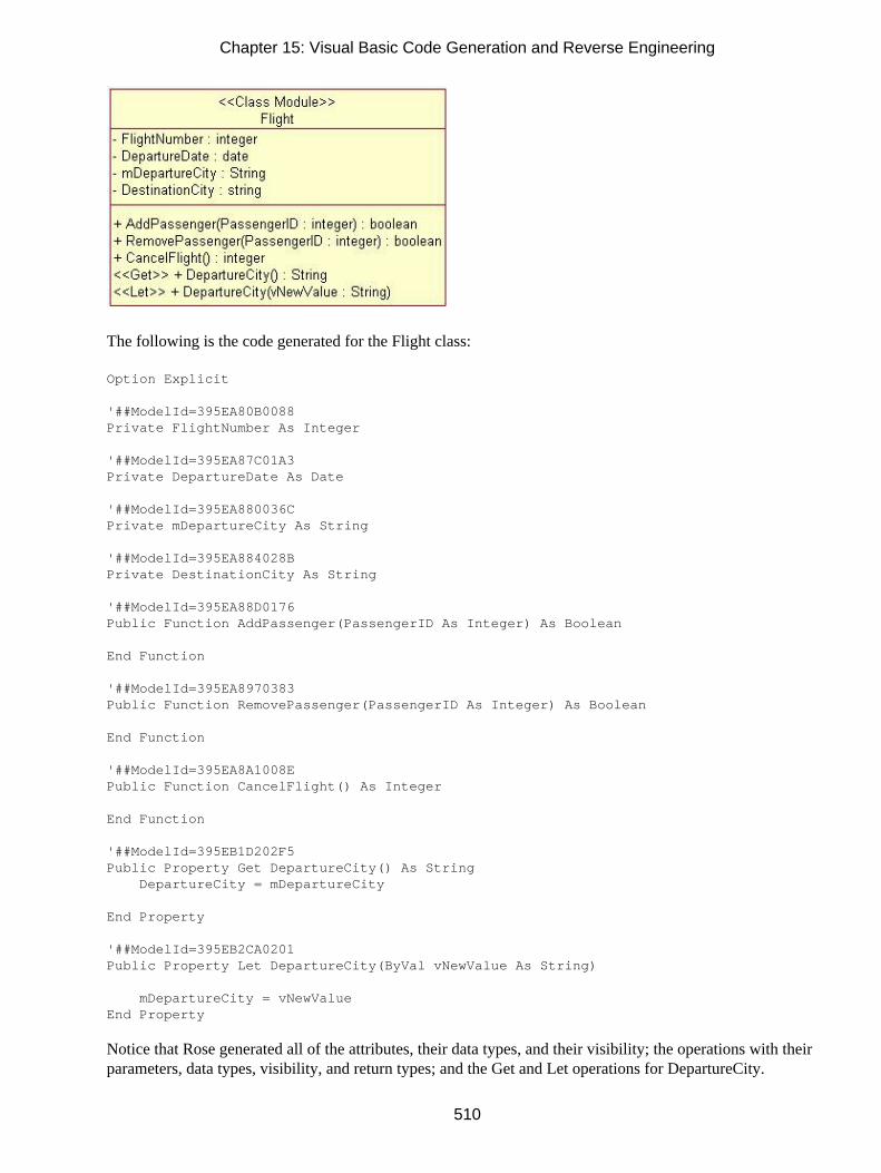
The following is the code generated for the Flight class:
Option Explicit
'##ModelId=395EA80B0088Private FlightNumber As Integer
'##ModelId=395EA87C01A3Private DepartureDate As Date
'##ModelId=395EA880036CPrivate mDepartureCity As String
'##ModelId=395EA884028BPrivate DestinationCity As String
'##ModelId=395EA88D0176Public Function AddPassenger(PassengerID As Integer) As Boolean
End Function
'##ModelId=395EA8970383Public Function RemovePassenger(PassengerID As Integer) As Boolean
End Function
'##ModelId=395EA8A1008EPublic Function CancelFlight() As Integer
End Function
'##ModelId=395EB1D202F5Public Property Get DepartureCity() As String DepartureCity = mDepartureCity
End Property
'##ModelId=395EB2CA0201Public Property Let DepartureCity(ByVal vNewValue As String)
mDepartureCity = vNewValueEnd Property
Notice that Rose generated all of the attributes, their data types, and their visibility; the operations with theirparameters, data types, visibility, and return types; and the Get and Let operations for DepartureCity.
Chapter 15: Visual Basic Code Generation and Reverse Engineering
510

The Get and Let methods were created because we set the option to create them using the Model Assistant.While Rose generates just the method headers for any operations you've added, it will generate the actual codefor Get and Let operations. This saves the programmers from the tedious task of generating and coding Getand Let operations for all of the attributes.
The Option Explicit line is included because the OptionExplicit class property for this class was set to True.
The ModelId lines were created to help synchronize Rose and Visual Basic during round−trip engineering.This feature allows you to change a method name, for example, in the Rose model or in the code, and still beable to synchronize the model with the code.
Warning Be careful not to change the ModelId numbers in the code.Much of the information in your Rose model will be used directly when generating code. For example, theattributes, operations, relationships, and class name will directly affect the code generated for each class.Other model properties, such as the documentation entered for the class, will not directly affect the code.These properties are created as comments in the generated code.
Table 15.6 lists properties of a class, and notes which of these properties will directly affect the codegenerated.
The Flight class has a stereotype of Class Module. Let's look at what is generated for some of the otherstereotypes. Note that while many different types of classes can be generated in Visual Basic, the Visual Basicadd−in will not generate parameterized classes.
Table 15.6: Effect of Class Properties on Generated Code
Property Effect on Code
Name Name in model will become class name
Type Directly affects the type of class created
Stereotype Directly affects the type of module file created (Class Module, MDI Form,etc.)
Export Control Does not affect generation
Documentation Generated as a comment
Cardinality Does not affect generation
Space Does not affect generation
Persistence Does not affect Visual Basic code generation, but does affect whether DDLcan be generated for the class
Concurrency Does not affect generation
Abstract Does not affect generation
Formal Arguments Formal arguments are included in the code for a parameterized class
Operations Generated in code
Attributes Generated in code
Relationships Generated in code
Chapter 15: Visual Basic Code Generation and Reverse Engineering
511

Form
The Form stereotype will create a Visual Basic form. Attributes become properties of the form. Operationsbecome methods of the form.
Rose can generate the default Visual Basic methods—such as the Initialize, Load, and Unload methods—forthe form. To decide which methods to generate, open the Model Assistant for the class and select theappropriate method(s) on the left side of the window.
As you select these methods, you will be given the option to change the method visibility (public, friend, orprivate). You can check the Replace Existing Body check box so that when Rose generates the method, thecode you've entered in the Default Body field will be generated:
Using the Template tab of the Model Assistant, you can set the following options:
•
Chapter 15: Visual Basic Code Generation and Reverse Engineering
512

DebugCode adds debug code to the Initialize and Terminate events. The default setting is False.
• Comments adds "Your code goes here…" comments to the methods of the class. The default setting isFalse.
• ErrorHandling adds error−handling code to the methods of the class. The default setting is False.
MDI Form
The MDIForm stereotype will create a Visual Basic MDI form. Attributes become properties of the form.Operations become methods of the form.
As with a Form stereotype, Rose can generate many default methods in an MDI form class. Open the ModelAssistant for the class and select the methods to generate. Then, enter the method visibility and the code to begenerated for that method.
Using the Template tab of the Model Assistant, you can set the following options:
• DebugCode adds debug code to the Initialize and Terminate events. The default setting is False.
• Comments adds "Your code goes here…" comments to the methods of the class. The default setting isFalse.
• ErrorHandling adds error−handling code to the methods of the class. The default setting is False.
ADO Class
The ADOClass stereotype will create an ADO class in Visual Basic, which will exhibit some persistentbehavior. Attributes of the class become properties of the ADO class. Operations become methods of the
Chapter 15: Visual Basic Code Generation and Reverse Engineering
513

ADO class.
In addition, Rose can generate the following properties. Use the Model Assistant to select the properties togenerate.
• BOF
• ConnectionString
• EOF
• Recordset
• mrs (generated by default)
Rose can generate a number of standard methods for the class, including the MoveFirst, MoveLast,MoveNext, MovePrevious, GetAll, and DeleteAll methods. Use the Model Assistant to select the operationsto generate.
By default, Rose will generate the Query method, which creates and fills a recordset using a query passed inas a parameter.
The following code is an example of what is generated for an ADO class:
Option Explicit
'Private constant with database connection string. Default from'template parameter ConnectionString (which defaults to an empty'string).'##ModelId=395EC4060255
Chapter 15: Visual Basic Code Generation and Reverse Engineering
514

Private Const ConnectionString As String = ""
'##ModelId=395EC406033BPrivate mrs As Recordset
'Public Property Get to get a reference to the private ADO'Recordset (mrs).'##ModelId=395EC40602A5Public Property Get Recordset() As Recordset Set Recordset = mrsEnd Property
'Private Function to return ADO Recordset from query sent as SQL'string input parameter. Creates a Connection and a Recordset.'Connects Recordset to the Connection, queries the database (with'the SQL string) which fills the recordset with the result.'Disconnects the Recordset from the Connection and closes the'Connection. Returns the created, queried and filled Recordset.'Uses the module level constant ConnectionString as connection'string on connection. Uses client side cursors on Connection.'##ModelId=395EC40602E1Private Function Query(ByVal SQL As String) As Recordset Dim aco As Connection Dim ars As Recordset
' Create objects Set aco = CreateObject("ADODB.Connection") Set ars = CreateObject("ADODB.Recordset")
' Open Connection aco.CursorLocation = adUseClient aco.ConnectionString = ConnectionString aco.Open
' Open Recordset ars.CursorType = adOpenKeyset ars.LockType = adLockBatchOptimistic ars.ActiveConnection = aco ars.Open SQL
' Return Recordset Set Query = ars
' Disconnect Recordset from Connection Set ars.ActiveConnection = Nothing
' Close Connection aco.CloseEnd Function
As with other stereotypes, you can set certain code−generation properties using the Template tab of the Modelassistant. For an ADO class, the following options are available:
• DebugCode adds debug code to the Initialize and Terminate events. The default setting is False.
•
Chapter 15: Visual Basic Code Generation and Reverse Engineering
515

Comments adds "Your code goes here…" comments to the methods of the class. The default setting isFalse.
• ErrorHandling adds error−handling code to the methods of the class. The default setting is False.
• MTSEnabled determines whether or not the class is MTS aware. If this option is set to True, Rose cangenerate a CreateInstance method and a Get method for the ObjectContext property.
• ConnectionString sets the database connection string to be used.
• TableName sets the name of the table corresponding to the class.
• PrimaryKeyFieldName sets the name of the primary key of the table corresponding to this class.
MTS Class
The MTS Class stereotype is used to model Microsoft Transaction Server (MTS) classes in Rose. Attributesyou've defined in Rose become attributes of the class in Visual Basic. Operations you've defined in Rosebecome methods of the Visual Basic class.
By default, an MTS class is not ADO−enabled. However, you can change this setting by using the ModelAssistant:
The following properties and methods are generated by default:
• ObjectContext property, which is the current MTS ObjectContext object
•
Chapter 15: Visual Basic Code Generation and Reverse Engineering
516

CreateInstance, which creates a new instance of an object
• SetAbort, which provides rollback functionality
• SetComplete, which commits a transaction
The following is an example of the code generated for an MTS class:
Option Explicit
'Private Property Get to return the current ObjectContext object'(assigned to the object by MTS). If the object is not running in'MTS, the returned value will be Nothing.'##ModelId=395EC3EA0395Private Property Get ObjectContext() As ObjectContext ' Return current ObjectContext Set ObjectContext = GetObjectContext()End Property
'Private Function to create a new instance of another object'specified as an input parameter (which is a ProgID string).'This method handles the creation of objects both running in'and outside of MTS. If there is an ObjectContext object for'the current object − i.e. it is running in MTS −'the CreateInstance method of the ObjectContext is called.'If not, the CreateObject API is called. This is the only'way you should use to make instances of new objects from'the class.'##ModelId=395EC3EA03D1Private Function CreateInstance(ByVal ProgID As String) As Variant ' Create object (inside MTS or not) If Not ObjectContext Is Nothing Then Set CreateInstance = ObjectContext.CreateInstance(ProgID) Else Set CreateInstance = CreateObject(ProgID) End IfEnd Function
'Calls the ObjectContext SetAbort method (if running in MTS) for'transactional Rollback behavior.'##ModelId=395EC3EB002FPrivate Sub SetAbort() ' Set Abort status on current ObjectContext object If Not ObjectContext Is Nothing Then ObjectContext.SetAbort End IfEnd Sub
'Calls the ObjectContext SetComplete method (if running in MTS)'for transactional Commit behavior.'##ModelId=395EC3EB0057Private Sub SetComplete() ' Set Complete status on current ObjectContext object If Not ObjectContext Is Nothing Then ObjectContext.SetComplete End IfEnd Sub
Chapter 15: Visual Basic Code Generation and Reverse Engineering
517

Using the Template tab of the Model Assistant, you can set the following code−generation options:
• DebugCode adds debug code to the Initialize and Terminate events. The default setting is False.
• Comments adds "Your code goes here…" comments to the methods of the class. The default setting isFalse.
• ErrorHandling adds error−handling code to the methods of the class. The default setting is False.
• ADOEnabled determines whether or not the class is ADO aware. If this option is set to True, Rosecan generate GetAll, GetNew, GetOne, Query, Save, and Update operations.
• ConnectionString sets the database connection string to be used.
• TableName sets the name of the table corresponding to the class.
• PrimaryKeyFieldName sets the name of the primary key of the table corresponding to this class.
• MTSTransactionMode sets the MTS support level (Not an MTS Object, No Transactions, RequiresTransaction, Uses Transaction, or Requires New Transaction).
Module
A Module stereotype becomes a Visual Basic module. Attributes become properties of the module. Operationsbecome methods of the module.
Using the Template tab of the Model Assistant, you can set the following:
• DebugCode adds debug code to the Initialize and Terminate events. The default setting is False.
• Comments adds "Your code goes here…" comments to the methods of the class. The default setting isFalse.
• ErrorHandling adds error−handling code to the methods of the class. The default setting is False.
Chapter 15: Visual Basic Code Generation and Reverse Engineering
518

Collection
A Collection stereotype becomes a Visual Basic collection. Attributes become properties of the collection.Operations become methods of the collection. In addition, Rose generates the following methods by default:
• Get Count, which returns the number of items in the collection. Rose will code this method for you
• Get Item, which returns an item from the collection. Rose will code this method for you
• Get Enum, which supports the enumeration of the collection for the For…Each syntax
• Add, which adds a new item to the collection
• Remove, which removes an item from the collection
• Initialize method, which creates an instance of the class in memory
• Terminate method, which does any "clean−up" work and removes an instance of the class frommemory
You can determine which methods to generate by using the Model Assistant:
Chapter 15: Visual Basic Code Generation and Reverse Engineering
519

The following code is an example of what is created in Visual Basic for a class with a stereotype ofCollection:
Option Explicit
'local variable to hold collection'##ModelId=395EC3EC0320Private mCol As New Collection
'used when retrieving the number of elements in the'collection. Syntax: Debug.Print x.Count'##ModelId=395EC3EB03BFPublic Property Get Count() As Long Count = mCol.CountEnd Property
'used when referencing an element in the collection'vntIndexKey contains either the Index or Key to the collection,'this is why it is declared as a Variant'Syntax: Set foo = x.Item(xyz) or Set foo = x.Item(5)'##ModelId=395EC3EC0009Public Property Get Item(vntIndexKey As Variant) As Variant Set Item = mCol(vntIndexKey)End Property
'this property allows you to enumerate'this collection with the For...Each syntax'##ModelId=395EC3EC006DPublic Property Get NewEnum() As IUnknown Set NewEnum = mCol.[NewEnum]End Property
'used when adding a new item to the collection'syntax: x.Add ayz'##ModelId=395EC3EC00A9Public Sub Add(Item As Variant, Optional Key As Variant, Optional Before As Variant, Optional After As Variant) If Len(Key) = 0 Then
Chapter 15: Visual Basic Code Generation and Reverse Engineering
520

mCol.Add Item Else mCol.Add Item, Key End IfEnd Sub
'used when removing an element from the collection'vntIndexKey contains either the Index or Key, which is why'it is declared as a Variant'Syntax: x.Remove(xyz)'##ModelId=395EC3EC018FPublic Sub Remove(vntIndexKey As Variant) mCol.Remove vntIndexKeyEnd Sub
'##ModelId=395EC3ED003CPrivate Sub Class_Initialize()
End Sub
'##ModelId=395EC3ED0078Private Sub Class_Terminate()
End Sub
Using the Template tab of the Model Assistant, you can set the following options for the collection:
• DebugCode adds debug code to the Initialize and Terminate events. The default setting is False.
• Comments adds "Your code goes here…" comments to the methods of the class. The default setting isFalse.
• ErrorHandling adds error−handling code to the methods of the class. The default setting is False.
• CollectionOf defines the class of which the collection is a grouping.
Note When reverse engineering a collection, Rose will create a class with a stereotype of Class Module, notCollection.
User Control
The User Control stereotype will create a Visual Basic user control. Attributes become properties of the usercontrol. Operations become methods of the user control. In addition to the operations you define in Rose, youcan generate many default methods for the user control, including Click, Double−Click, KeyDown, Resize,and Show.
Using the Model Assistant, select the method(s) to be generated in Visual Basic for the user control.
Chapter 15: Visual Basic Code Generation and Reverse Engineering
521

On the Template tab, you can set the following options:
• DebugCode adds debug code to the Initialize and Terminate events. The default setting is False.
• Comments adds "Your code goes here…" comments to the methods of the class. The default setting isFalse.
• ErrorHandling adds error−handling code to the methods of the class. The default setting is False.
Property Page
The PropertyPage stereotype will create a Visual Basic property page. Attributes become properties of thepage. Operations become methods of the page. As with many other stereotypes, Rose can generate defaultmethods for you through the Model Assistant:
Chapter 15: Visual Basic Code Generation and Reverse Engineering
522

On the Template tab, you can set the following options:
• DebugCode adds debug code to the Initialize and Terminate events. The default setting is False.
• Comments adds "Your code goes here…" comments to the methods of the class. The default setting isFalse.
• ErrorHandling adds error−handling code to the methods of the class. The default setting is False.
Data Report
A DataReport−stereotyped class is generated as a Visual Basic data report. Any attributes of the class becomeproperties of the data report. Any operations become methods in the data report. In addition, Rose cangenerate standard methods for you:
The following is an example of a data report generated from Rose:
Chapter 15: Visual Basic Code Generation and Reverse Engineering
523

On the Template tab of the Model Assistant, you can set the following options for the data report:
• DebugCode adds debug code to the Initialize and Terminate events. The default setting is False.
• Comments adds "Your code goes here…" comments to the methods of the class. The default setting isFalse.
• ErrorHandling adds error−handling code to the methods of the class. The default setting is False.
Data Environment
A class with a stereotype of Data Environment will create a DataEnvironment class in Visual Basic. As withother stereotypes, attributes and operations are implemented as properties and methods of the generated class.
When generating a data environment, Rose will add a connection object to the generated class. You can thenset up the connection, including the connection type (ODBC, etc.) and data source using Visual Basic.
Rose can also generate Initialize and Terminate methods for the data environment. Use the Model Assistant toset which operations to generate:
Chapter 15: Visual Basic Code Generation and Reverse Engineering
524

On the Template tab of the Model Assistant, you can set the following options:
• DebugCode adds debug code to the Initialize and Terminate events. The default setting is False.
• Comments adds "Your code goes here…" comments to the methods of the class. The default setting isFalse.
• ErrorHandling adds error−handling code to the methods of the class. The default setting is False.
The following is an example of the data environment created from Rose:
User Connection
The UserConnection stereotype will create a Visual Basic user connection. Attributes become properties ofthe connection. Operations become methods of the connection. You can set up Rose to generate default
Chapter 15: Visual Basic Code Generation and Reverse Engineering
525

methods through the Model Assistant:
On the Template tab of the Model Assistant, you can set the following options:
• DebugCode adds debug code to the Initialize and Terminate events. The default setting is False.
• Comments adds "Your code goes here…" comments to the methods of the class. The default setting isFalse.
• ErrorHandling adds error−handling code to the methods of the class. The default setting is False.
Once the user connection has been created, you can use Visual Basic to set the connection details, add queries,and complete the code for the connection.
User Document
A User Document stereotype becomes a Visual Basic user document. Attributes become properties of the userdocument. Operations become methods of the user document. The Model Assistant will enable you to set thedefault methods to be generated.
Chapter 15: Visual Basic Code Generation and Reverse Engineering
526

Using the Template tab of the Model Assistant, you can set the following:
• DebugCode adds debug code to the Initialize and Terminate events. The default setting is False.
• Comments adds "Your code goes here…" comments to the methods of the class. The default setting isFalse.
• ErrorHandling adds error−handling code to the methods of the class. The default setting is False.
Note You cannot generate a user document that is assigned to a component with a Standard EXE stereotype.Map the user document to another component (ActiveX EXE, for example) before generating code.
Type and Enum
A Type or Enum class must be modeled as a class nested within another class. To do this, open thespecification of the nesting class and select the Nested tab. Right−click in the whitespace to add a new nestedclass, and set the stereotype of the nested class to Type or Enum.
Once you have added the nested class, double−click it to open the nested class specification. Click theAttributes tab to add one or more attributes to the nested class before generating code.
The following is an example of a Type and Enum class generated from Rose:
Option Explicit
'##ModelId=39600F880341Public Enum VBEnum '##ModelId=3960106A01BF EnumAttribute = 4End Enum
'##ModelId=39600FA10206Public Type VBType '##ModelId=3960107A0245
Chapter 15: Visual Basic Code Generation and Reverse Engineering
527

TypeAttribute As BooleanEnd Type
Add−In Designer
The Add−In Designer stereotype will create a Visual Basic add−in designer. Attributes become properties ofthe designer, while operations become methods of the designer. You can set up Rose to generate defaultmethods through the Model Assistant:
On the Template tab of the Model Assistant, you can set the following options:
• DebugCode adds debug code to the Initialize and Terminate events. The default setting is False.
• Comments adds "Your code goes here…" comments to the methods of the class. The default setting isFalse.
• ErrorHandling adds error−handling code to the methods of the class. The default setting is False.
Once the designer has been created, you can use Visual Basic to set the details. The following is an exampleof an add−in designer created from Rose:
Chapter 15: Visual Basic Code Generation and Reverse Engineering
528

DHTML Page
A class with a stereotype of DHTMLPage will be implemented as a DHTML page in Visual Basic. As withother stereotypes, attributes and operations of the class in Rose become properties and methods of the VisualBasic class.
Using the Model Assistant, you can select the methods to be generated in the code:
On the Template tab of the Model Assistant, you can set the following options:
• DebugCode adds debug code to the Initialize and Terminate events. The default setting is False.
• Comments adds "Your code goes here…" comments to the methods of the class. The default setting isFalse.
•
Chapter 15: Visual Basic Code Generation and Reverse Engineering
529

ErrorHandling adds error−handling code to the methods of the class. The default setting is False.
Note You cannot generate a DHTML page that is assigned to a component with a Standard EXE stereotype.Map the DHTML page to another component (ActiveX EXE, for example) before generating code.
Attributes
Aside from the class itself, Rose will generate the attributes for the class. For each attribute, Rose will include:
• Visibility (public or private only; protected visibility is not allowed)
• Data type
• Default value
• Get operation (optional)
• Set operation (optional)
• Let operation (optional)
For a given attribute, Rose will generate code similar to the following:
Option Explicit
'##ModelId=39601FD70178Private mPrivateAttribute As Integer
'##ModelId=39602033026APublic Property Get PrivateAttribute() As Integer PrivateAttribute = mPrivateAttributeEnd Property
'##ModelId=396020340059Public Property Let PrivateAttribute(ByVal vNewValue As Integer) mPrivateAttribute = vNewValueEnd Property
You can control whether the Get, Let, and Set operations are generated by using the Model Assistant for theclass. In the Properties portion of the treeview, find the appropriate attribute and check the Get, Let, or Setmethod check boxes under the property to generate those methods. You can also change the attribute visibilityand data type using the Model Assistant.
An attribute with a stereotype of Const will be generated as a Visual Basic constant. Use the Initial Value fieldin the attribute specifications to set the value of the constant. In this example, we created a constant calledDaysInWeek with an initial value of 7. The following line of code was generated:
Private Const DaysInWeek As Integer = 7
Chapter 15: Visual Basic Code Generation and Reverse Engineering
530

By default, Rose will prefix the attribute name with an "m" when generating code. To change the prefix used,select Tools → Visual Basic → Properties, and edit the Data Member Prefix field.
Operations
Rose generates code for each of the operations in the class. For each operation, the generated code includesthe operation name, the parameters, the parameter data types, and the return type. Each operation will generatecode similar to the following:
'This is documentation entered through Rose for the PublicOperation method.''##ModelId=3960239403E1Public Function PublicOperation(Argument1 As Integer) As Boolean
End Function
As you can see, the full operation signature is generated in the code. Any documentation you enter for theoperation is also generated as a comment in the code. If you enter information for the operation protocol,qualifications, exceptions, time, space, preconditions, semantics, or postconditions, this information will notbe included in the generated code. Once you have generated the code, you insert the implementation code foreach operation.
As with other model elements, you can control the code generated for an operation by modifying itscode−generation properties. For example, you can create static functions by modifying the IsStatic property.The code−generation properties for operations are listed earlier in this chapter, in Table 15.3, for yourreference.
Bidirectional Associations
To support bidirectional associations, Rose will generate attributes in the code. Each of the classes in therelationship will contain an attribute to support the association. Unlike Visual C++, Rose Visual Basic doesnot require that you assign role names in order to generate attributes to support the relationship. However, ifyou do not assign role names, the attributes will be called NewProperty. If you do assign role names, Rosewill use the role names as the names of the generated attributes. For example, let's look at the code generatedfor the following:
Here is the Visual Basic code generated for these two classes. First, let's look at the Passenger class:
Option Explicit
'##ModelId=39614F5402F7Private FirstName As String
'##ModelId=39614F5702B5Private LastName As String
Chapter 15: Visual Basic Code Generation and Reverse Engineering
531

'##ModelId=39614F5A01F1Private Address As String
'##ModelId=39614F5D0250Private City As String
'##ModelId=39614F5F01EEPrivate State As String
'##ModelId=39614F610179Private Zip As Long
'##ModelId=39614F6B00DDPrivate Phone As String
'##ModelId=39614F990350Public Account As FrequentFlyerAccount
Now let's look at the FrequentFlyerAccount class:
Option Explicit
'##ModelId=39614F7300C1Private AccountID As int
'##ModelId=39614F7503A9Private NumberOfMiles As int
'##ModelId=39614F7A02C0Private DateEstablished As Date
'##ModelId=39614F99035APublic AccountHolder As Passenger
'##ModelId=39614F8902FDPublic Function UseMiles(Miles As int) As int
End Function
'##ModelId=39614F840089Public Function AddMiles(Miles As int) As int
End Function
'##ModelId=39614F7300C1Private AccountID As int
'##ModelId=39614F7503A9Private NumberOfMiles As int
'##ModelId=39614F8902FDPublic Function UseMiles(Miles As int) As int
End Function
'##ModelId=39614F840089Public Function AddMiles(Miles As int) As int
End Function
Chapter 15: Visual Basic Code Generation and Reverse Engineering
532

As you can see, Rose will automatically generate attributes on both sides of the bidirectional associationrelationship. With the AccountHolder attribute, FrequentFlyerAccount can easily access Passenger. Using theAccount attribute, Passenger can easily access FrequentFlyerAccount.
Tip Remember that if you supply no role names, the default (and less useful) attribute name NewPropertywill be used. If you supply a role name, that role name will be used as the attribute name.
In the Model Assistant, you can elect to generate Get and Set methods for the attribute generated to supportthe relationship:
Rose will create the methods and then code them for you:
'##ModelId=396152BE0268Public Property Get Account() As FrequentFlyerAccount Set Account = mAccountEnd Property
'##ModelId=396152C00333Public Property Set Account(ByVal vNewValue As FrequentFlyerAccount) Set mAccount = vNewValueEnd Property
Note that this association has a multiplicity of one to one. See below for a discussion of how other multiplicitysettings will affect code generation.
Unidirectional Associations
As with bidirectional associations, Rose will generate attributes to support unidirectional associations. With aunidirectional association, however, an attribute is generated only at one end of the relationship.
Chapter 15: Visual Basic Code Generation and Reverse Engineering
533

Again we have the Passenger and FrequentFlyerAccount classes, but this time the relationship isunidirectional. An attribute will be created inside Passenger, but not inside FrequentFlyerAccount. Thefollowing lines of code are from Passenger:
'##ModelId=39614F990350Private Account As FrequentFlyerAccount
As you can see, Rose will generate a private attribute for the relationship at only one end of the association.Specifically, it will generate an attribute in the client class, but not in the supplier class.
The code generated in the supplier class includes all of the code lines discussed in the previous section aboutbidirectional associations. With a bidirectional association, each class is given a new attribute, and the codediscussed in the previous section is included in both classes. With a unidirectional association, the code isincluded only in the client class.
Again, note that the multiplicity here is one to one. Let's take a look at how code is affected when themultiplicity settings are changed.
Associations with a Multiplicity of One to Many
In a one−to−one relationship, Rose can simply create the appropriate attributes to support the association.With a one−to−many relationship, however, one class must contain a set of the other class.
To begin, let's look at an example.
In this case, we have a one−to−many relationship. As we saw in the previous section, Flight can simplygenerate an attribute that is a reference to Passenger. However, a simple attribute in the Flight class won't beenough. Instead, the attribute generated in Flight must use a sort of container class or an array as its data type.(Rose will use a collection as the default.) The following code is generated in the Flight class:
'##ModelId=396154B0001FPublic Passenger As Collection
Rose provides you with the Collection type as a container class. If you would rather, you can use an array byspecifying the Subscript role property. To do so, open the specification window for the relationship and selectthe Visual Basic A or Visual Basic B tab. Then specify a value for the Subscript code−generation property.Here, we use a subscript of 3:
'##ModelId=396154B0001FPublic Passenger(3) As Passenger
Associations with a Multiplicity of Many to Many
The code generated here is similar to that created for a one−to−many relationship. In this type of relationship,however, Rose will generate container classes on both ends of the relationship.
Chapter 15: Visual Basic Code Generation and Reverse Engineering
534

Let's look at the code generated for the following relationship:
In this situation, container classes are used at both ends of the relationship. The code that is generated willlook something like the following two classes.
First, the Flight class will contain:
'##ModelId=396154B0001FPublic Passenger As Collection
Next, the Passenger class will contain:
'##ModelId=396154B00021Public Flight As Collection
Again, Rose uses a collection class as the default container, but you can change this to an array by modifyingthe Subscript code−generation property in the relationship specification window.
Reflexive Associations
A reflexive association is treated much the same as an association between two classes. For the followingsituation,
this code is generated:
'##ModelId=3961578B0369Public NewProperty As Collection
As with a regular association, an attribute is created inside the class to support the relationship. If themultiplicity is one, a simple attribute is created. If the multiplicity is more than one, a container class is used.
As you can see, the code generated here is very similar to the code generated in a typical one−to−manyrelationship. In this situation, Class A contains an attribute of type Collection.
Aggregations
There are two types of aggregation relationships: by value and by reference. With a by−value relationship,one class contains another. With a by−reference relationship, one class contains a reference to another. Both
Chapter 15: Visual Basic Code Generation and Reverse Engineering
535

of these types of relationships are generated identically in Rose Visual Basic.
The code generated for an aggregation relationship is the same as the code generated for an associationrelationship. Let's look at an example:
The aggregation relationship tells us that, conceptually, a fleet is made up of many aircraft. When we generatecode, however, Rose doesn't care whether there is an association or an aggregation between the classes. TheFleet class will contain a collection of Airplanes:
'##ModelId=396159720233Public NewProperty As Collection
Dependency Relationships
With a dependency relationship, no attributes are created. If there is a dependency between ClassA andClassB, no attributes will be created in either ClassA or ClassB.
Generalization Relationships
A generalization relationship in UML becomes an inheritance relationship in object−oriented languages.However, Visual Basic does not support inheritance. Instead, a generalization can become an implementsdelegation in Visual Basic. In your Rose model, a generalization relationship is shown as follows:
No special code will be inserted into the parent class. This allows it to be reusable and independent of thechild class.
The child class contains three special areas of code. First, an Implements Parent statement is added. Second,an instance of the parent class is created inside the child class. Finally, copies of the parent's public methodsare inserted into the child class.
Option Explicit
Chapter 15: Visual Basic Code Generation and Reverse Engineering
536

'##ModelId=39615A930379Implements Parent
'##ModelId=39615AA50180Private mParentObject As New Parent
'##ModelId=39615AA501C6Private Sub Parent_PublicOperation() Call mParentObject.PublicOperationEnd Sub
Reverse Engineering
As with code generation, reverse engineering with Visual Basic is done through a wizard. Rose Visual Basicincludes a Model Update Wizard that will walk you through the steps of selecting the class(es) to reverseengineer and pulling them into your Rose model.
To begin the process, select Tools → Visual Basic → Update Model from Code. The reverse−engineeringwizard will begin, as shown in Figure 15.11.
Figure 15.11: Visual Basic reverse−engineering wizard
If you have already created some Visual Basic components, Rose will list them and give you the option toselect the components to reverse engineer. If not, Rose will prompt you to create a component, as shown inFigure 15.12.
Chapter 15: Visual Basic Code Generation and Reverse Engineering
537

Figure 15.12: Creating a Visual Basic component
To create a component, select Add a Visual Basic Component, or press Ctrl+A. Then select the type ofcomponent to create (Standard EXE, ActiveX EXE, ActiveX DLL, or ActiveX Control) and press Add.
When you are returned to the Select Components and Classes window, right−click the new component andselect Properties. In the Project File field, enter the Visual Basic project to reverse engineer:
Once you have added a component (or if you already had components added), Rose will prompt you to selectthe components to reverse engineer. Press Next to see a summary screen, and then press Finish to start thereverse−engineering process.
If you did not start the project by using the Visual Basic framework, Rose will first reverse engineer a COMpackage with subpackages containing the standard Visual Basic classes and types:
Chapter 15: Visual Basic Code Generation and Reverse Engineering
538

Rose will then, of course, reverse engineer the classes you selected using the wizard. In the followingexample, we reverse engineered some of the classes in our airline example.
Each Visual Basic class is reverse engineered as a Rose class with the appropriate stereotype. Table 15.7 liststhe Visual Basic class types and their corresponding Rose model stereotypes.
Table 15.7: Visual Basic−to−Rose Mapping
Visual Basic Class Rose Stereotype
Class Module Class Module
Interface Class Module with Public visibility
Form Form
MDI Form MDI Form
DHTML Page DHTML Page
Property Page Property Page
Interface Class Module with Public visibility
Module Module
User Connection User Connection
User Control User Control
User Document User Document
Web Class Web Class
Template Web Item Template Web Item
Custom Web Item Custom Web Item
Data Environment Data Environment
Data Report Data Report
Add−In Designer Add−In Designer
Collection Class Module
Summary
In this chapter, we took a look at how various Rose model elements are implemented in Visual Basic. Usingthe code−generation properties for classes, packages, attributes, operations, associations, aggregations, and
Chapter 15: Visual Basic Code Generation and Reverse Engineering
539

other model elements, you have a great deal of control over what gets generated. Through thecode−generation and reverse−engineering capabilities of Rose, you can keep your source code and Rosemodel synchronized.
Again, the steps needed to generate code are as follows:
1. Create components.
2. Assign classes to components.
3. Set the code−generation properties.
4. Select a class or component to generate on a Class or Component diagram.
5. Select Tools → Visual Basic → Update Code to start the Code Generation Wizard.
6. Select Tools → Visual Basic → Browse Source Code to view the generated code.
To reverse engineer a Visual Basic project, follow these steps:
1. Create a component and assign a Visual Basic project to the component.
2. Select Tools → Visual Basic → Update Model from Code.
3. Select the component(s) and class(es) to update.
4. Select Finish to complete the process.
In the next chapter, we will explore one of the newest features of Rational Rose: the XML DTD add−in. Thisnew feature gives you the capability of modeling not only your application, but also the structure of yourXML DTD files. You can use Rose to reverse engineer and visualize existing DTD structures or to model andgenerate new ones. As we will see in the next few chapters, Rose now has the ability to model your entireapplication: object model, XML DTD structure, database structure, and web components.
Chapter 15: Visual Basic Code Generation and Reverse Engineering
540

Chapter 16: XML DTD Code Generation and ReverseEngineering
Overview
We know that Rose can be used to model the design of a software system. It can be used to model thedatabase and the business surrounding the system. But there is one more piece in many software systems thatwe haven't addressed so far: the use of Extensible Markup Language (XML). To get a complete picture of thesystem, we need to be able to see all of the pieces, including XML.
In this chapter, we'll discuss one of the new add−ins available for Rose: the integration with XML DTD(document type definition). As XML gains popularity in the industry, this new tool gives a design team theability to model a complete software solution, including the code in C++, Visual Basic, or Java and the XMLDTD components.
In this chapter, we'll take a look at how Rose can be used to model DTD elements, how DTD can be generatedfrom Rose, and how DTD can be reverse engineered into Rose. Sometimes, a DTD can be just as complex asa system design model. Keeping track of the elements in a DTD and ensuring that the correct syntax is usedcan be a challenge. Rose gives you a picture of the DTD structure, making it easier for you to design the DTDand validate the design. Rose also provides you with a syntax check, so you can be sure the syntax is correctbefore you generate code.
Although we use the term "code generation," it is important to note that XML is not source code as we wouldtypically think of it. XML is not a programming language, but rather a standard that can be used to exchangedata between applications. Like HTML, XML includes tags that provide the interpreter with informationabout the data contained within the document. Unlike HTML, however, XML can include custom−definedtags. You can create a new standard data format using these custom tags and exchange data with anyone else,as long as they know the format.
This is where a DTD file comes in. The DTD includes metadata, or data about the data. It outlines thestructure used by the XML file. An XML parser then uses the DTD file in conjunction with the XML fileitself to interpret the file.
• Setting XML DTD code−generation properties
• Generating DTD files from your Rose model
• Mapping Rose elements to DTD constructs
• Reverse engineering DTD files
541

Introduction to XML DTD
XML evolved as the need arose to structure data on the Web. HTML is very useful for displaying information,but it contains only a limited number of tags that you can use when creating a document. XML is much moreflexible; you can create whatever tags you need to effectively describe the data in the document.
The tags are defined in the DTD file for the XML file. A DTD document is comprised of elements that definethe types of data that can be included in the XML file.
Elements
An element is defined in three key pieces. The first is the ELEMENT keyword, which indicates that the text tofollow defines an element. The second is the name of the element. Each element name must be unique.Further, XML does not allow an element to begin with the characters "xml" in upper or lower case. Finally,the content model defines the items that make up the element. For example, here we have an element called"book" that is made up of a title, table of contents, introduction, and section.
<!ELEMENT book (title, tableofcontents, introduction, section)>
The title, tableofcontents, introduction, and section make up the content model. An element can also containtext in its content model. We can indicate this by using the notation #PCDATA in the content model. Forexample:
<!ELEMENT title (#PCDATA)>
Here we have an element called title, which is simply a string of text. An element may contain other elements,text (PCDATA), or both in its content model.
This is useful, but it doesn't let us know whether the items in the content model are required or how manyitems can be contained within the element. There are three symbols we can use here to get more information:
• A plus sign (+) indicates that the item is required and that there may be more than one.
• An asterisk (*) indicates that the item is not required and that there may be more than one.
• A question mark (?) indicates that the item is not required and that there can be only one.
Using these symbols, we return to our example:
<!ELEMENT book (title+, tableofcontents?, introduction?, section+)>
Our example says that a book must have a title. It may or may not have a table of contents or introduction, andwill never have more than one table of contents or introduction. It must have at least one section, but can havemore than one.
As you can see, we can get a lot of information about the element by including these three symbols in thecontent model. They are included in the DTD to spell out the rules that apply to the elements and the items in
Chapter 16: XML DTD Code Generation and Reverse Engineering
542

their content models.
Notice that the items in the content model are separated by commas. Commas indicate that the items mustappear in the order they are listed in the content model. Our book must first have a title, then a table ofcontents, then an introduction, and finally its sections.
In some situations, however, you may want to indicate that there is a choice involved. To show a choice, youcan use a choice operator (|). The notation would then be:
<!ELEMENT A (B|C)>
This notation suggests that element A is comprised of B or C.
Attributes
An element may have one or more attributes. An attribute is simply a piece of information about the element.Like attributes in the object model, an entity's attribute has a name, data type, and optional default value.
An attribute is declared using the following notation:
<!ATTLIST ElementName AttributeName DataType DefaultValue>
For example:
<!ATTLIST Author Name CDATA><!ATTLIST Employee EmpID ID>
If an element has more than one attribute, they are listed as follows:
<!ATTLIST Employee Name CDATA Address CDATA Phone CDATA>
There are three additional keywords that can be added to an attribute. The keyword #REQUIRED indicatesthat the attribute is mandatory. The #IMPLIED keyword indicates that the attribute is not required. Finally,the #FIXED keyword indicates that the attribute's value cannot change. If the attribute is fixed, it must begiven a default value.
To assign a default value to an attribute, enter the value at the end of the attribute declaration. For example:
<!ATTLIST book language CDATA "Spanish">
This declaration assigns the default value "Spanish" to a book's language.
Sometimes you want to set a list of valid values for an attribute. In our example, let's assume books must be inSpanish, English, or Japanese. We would specify this as follows:
<!ATTLIST book language CDATA (Spanish | English | Japanese) "Spanish">
Here, the language must be Spanish, English, or Japanese, and the default is Spanish.
Entities and Notations
An entity is used when you want to use a simple word to represent a more complex string. It is a way to enter
Chapter 16: XML DTD Code Generation and Reverse Engineering
543

a lot of information by simply typing the entity name. Entities help simplify documents and keep you fromrepetitive typing.
An entity may be internal or external. An internal entity is defined in the DTD. An external entity is definedoutside the DTD and corresponding XML document (for example, in another XML document). The SYSTEMkeyword indicates that the entity is an external entity. External entities may be parsed or unparsed.
Some examples of entities include text strings, external files, and special characters.
Text Strings
If there is a long text string that is repeated many times, an entity can be used to represent the string. Forexample, instead of typing "the quick brown fox jumps over the lazy dog," you can just type "&lazydog." Theformat of this type of entity looks like this:
<!ENTITY EntityName "entity text">
For example,
<!ENTITY lazydog "the quick brown fox jumps over the lazy dog">
We define the entity "lazydog" as the string "the quick brown fox jumps over the lazy dog." Now to use theentity, all we have to do is type an ampersand (&) followed by the entity name. Anywhere we type"&lazydog," the XML parser will replace "&lazydog" with the full phrase.
External Files
An entity can be used to represent an external XML file. In this situation, we need to add the SYSTEMkeyword. The entity declaration looks like this:
<!ENTITY EntityName SYSTEM "entity location">
For example, if you have the text from the Declaration of Independence in another file, you can define anentity and use that entity name rather than type all of the text. Our entity declaration would look like this:
<!ENTITY Independence SYSTEM "/independence.xml">
Now all we need to do is use the keyword &Independence wherever we want a reference to the external file.
Special Characters
When you need to use a special character, such as ®, you can define an entity that, when used, will bereplaced by that special character. This saves you the headache of trying to remember the decimal value of thespecial character.
Parsed and Unparsed Entities and Notations
An entity may be parsed or unparsed. A parsed entity is one that follows the rules we described earlier in thissection; when the XML parser encounters the entity, it replaces the entity name with the text or file the entityrepresents.
Chapter 16: XML DTD Code Generation and Reverse Engineering
544

The XML parser will ignore an unparsed entity. So why use unparsed entities? They provide a way to includethings such as graphics files, video, audio, or other files that are not in XML format. When the XML parsersees an unparsed entity, it will call an application that can process the entity. For example, it may call anapplication to run the video, which will have an entity declaration that looks like this:
<!ENTITY MyVideo SYSTEM "C:\Videos\Vacation.vid">
The XML parser knows which application to call on to process the entity because of a construct called anotation. A notation identifies the application to be used to process a particular entity, and provides theapplication location. A notation is documented as follows:
<!NOTATION NotationName SYSTEM "notation location">
For example:
<!NOTATION Video SYSTEM "C:\MyVideoPlayer.exe">
The picture is almost complete, but we're still missing one piece. How does the XML parser know that theVideo notation applies to the MyVideo entity? We need to add one last piece to the entity declaration, to tie itto the Video notation. We use the NDATA keyword, followed by the notation name. So now our examplecontains the two lines:
<!ENTITY MyVideo SYSTEM "C:\Videos\Vacation.vid" NDATA Video><!NOTATION Video SYSTEM "C:\MyVideoPlayer.exe">
DTD−to−UML Mapping
When reverse engineering or generating DTD, Rose will map the different DTD constructs to classes with theappropriate stereotype. In the remainder of this chapter, we will discuss in detail how the DTD constructs mapto Rose model elements. Table 16.1 lists the XML DTD constructs and their corresponding model elements.
Table 16.1: DTD−to−Rose Mapping
DTD Construct Rose Element
Element Class with stereotype DTDElement
Attribute Attribute of element class
Entity Class with stereotype DTDEntity
Notation Class with stereotype DTDNotation
Empty element type Class with stereotype DTDElementEmpty
Any element type Class with stereotype DTDElementAny
Parsed character element type Class with stereotype DTDElementPCDATA
Content model with items separated by "," Class with stereotype DTDSequenceGroup
Content model with items separated by "&" Class with stereotype DTDSet
Content model with items separated by "|" Class with stereotype DTDChoiceGroup
Chapter 16: XML DTD Code Generation and Reverse Engineering
545

DTD Code−Generation Properties
Rose XML provides DTD specification windows for the classes in the model. You will see a slightly differentwindow for each DTD stereotype supported by Rose. In this section, we'll look at the different properties youcan set for classes with the various DTD stereotypes.
Regardless of the stereotype, to view the specification window, you right−click the class and select OpenSpecification.
You can set code−generation properties for the following items:
• Project
• Classes
• Attributes
• Roles
• Components
In this section, we will use the following DTD example to discuss the different code−generation properties.This is an example of a DTD file that defines a book:
<!—The following DTD defines a book—><!ELEMENT book (title,tableofcontents,introduction?,section+)><!ELEMENT chapter (title,paragraph+)><!ATTLIST chapterChapterNum ID #REQUIRED Description CDATA #REQUIRED NumPages CDATA #REQUIRED ><!ELEMENT introduction (paragraph+)><!ELEMENT section (title,chapter+,paragraph+)><!ELEMENT paragraph (#PCDATA)><!ELEMENT title (#PCDATA)><!ELEMENT tableofcontents (#PCDATA)>
Project Properties
The project specifications control the editor that will be used, and set the different code−generation optionsfor the overall project. To view the project properties, select Tools → XML_DTD → Project Specification.The window shown in Figure 16.1 will appear.
Chapter 16: XML DTD Code Generation and Reverse Engineering
546

Figure 16.1: XML Project Specification window
The XML project properties are listed in Table 16.2. The settings here will affect all classes, relationships, andother elements in the Rose model.
Table 16.2: XML Project Properties
Property Purpose Default
Editor Controls the editor, which uses, views, and edits a DTD. Selectfrom Built−In (Rose editor) or Windows Shell, or type in thename of a third−party editor you would like to use.
Built−In
Stop On Error Stops the code−generation process if an error is encountered.True
Create MissingDirectories
Create directories for the components in the model. True
Class Properties
Rose XML provides different code−generation properties for the different types of classes you can create.Each type of class has its own stereotype, such as DTDElement or DTDEntity. In this section, we'll look ateach of these stereotypes and examine the code−generation properties that can be set.
In the "Generated Code" section later in this chapter, we will take a closer look at each of these types ofclasses, discuss their purposes, and describe the UML notation used for the class.
Before you attempt to generate code, you should review the code−generation properties for your classes tohelp ensure that the code you get is the code you expected to get. Let's begin by looking at a class with astereotype of DTDElement.
Chapter 16: XML DTD Code Generation and Reverse Engineering
547

DTDElement
A class with a stereotype of DTDElement corresponds to an ELEMENT declaration in a DTD file. To expandon our earlier example (see the "Elements" section), there are several elements: book, tableofcontents,introduction, section, chapter, paragraph, and title. Each of these is modeled as a class with a stereotype ofDTDElement.
The code−generation properties for a DTD element include the element name, type, and comments. Figure16.2 shows the Class Specification window for a DTD element.
Figure 16.2: Class Specification window for a DTD element
You can change the name of the element in the Name field. The Type field sets the stereotype of the element.The stereotypes include:
• DTDEmpty, which is an empty element, suggesting that the element cannot contain text or otherelements. However, these elements can still have attributes.
• DTDPCDATA, which is an element that can contain text.
• DTDAny, which is an element that can contain text or other elements.
Finally, you can enter a comment for the element in the DocComment field. Any comments you enter herewill appear as comments in the generated DTD.
Chapter 16: XML DTD Code Generation and Reverse Engineering
548
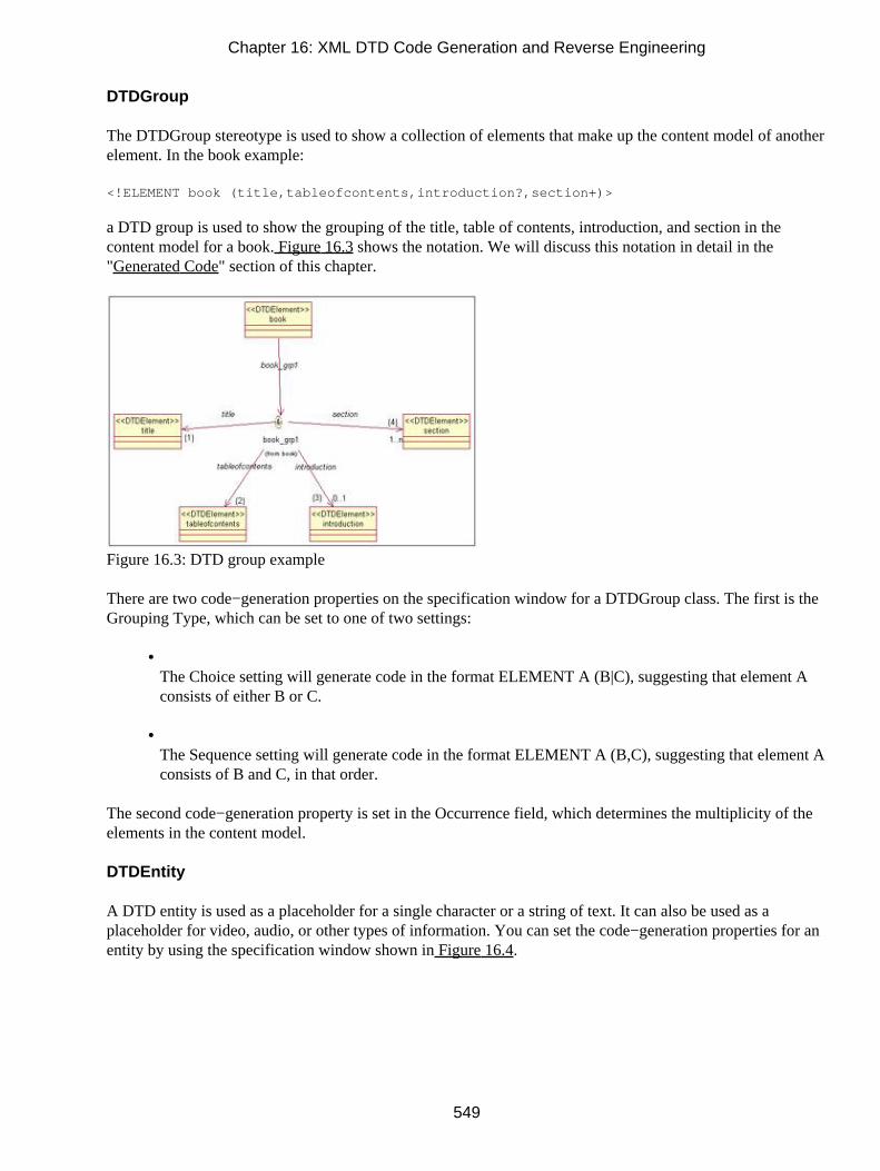
DTDGroup
The DTDGroup stereotype is used to show a collection of elements that make up the content model of anotherelement. In the book example:
<!ELEMENT book (title,tableofcontents,introduction?,section+)>
a DTD group is used to show the grouping of the title, table of contents, introduction, and section in thecontent model for a book. Figure 16.3 shows the notation. We will discuss this notation in detail in the"Generated Code" section of this chapter.
Figure 16.3: DTD group example
There are two code−generation properties on the specification window for a DTDGroup class. The first is theGrouping Type, which can be set to one of two settings:
• The Choice setting will generate code in the format ELEMENT A (B|C), suggesting that element Aconsists of either B or C.
• The Sequence setting will generate code in the format ELEMENT A (B,C), suggesting that element Aconsists of B and C, in that order.
The second code−generation property is set in the Occurrence field, which determines the multiplicity of theelements in the content model.
DTDEntity
A DTD entity is used as a placeholder for a single character or a string of text. It can also be used as aplaceholder for video, audio, or other types of information. You can set the code−generation properties for anentity by using the specification window shown in Figure 16.4.
Chapter 16: XML DTD Code Generation and Reverse Engineering
549

Figure 16.4: Class Specification window for a DTD entity
Table 16.3 lists the entity code−generation properties and the purpose of each.
Table 16.3: DTD Entity Properties
Property Purpose
Parameter Entity Determines whether this is a parameter entity.
External Entity Determines whether this is an external entity, which refers to a filethat is outside the XML DTD.
Internal Entity Value Sets the character, string, or other entity to use in place of aninternal entity.
External Entity System ID Location (URL) of the external file.
External Entity Public ID Alternate location of the external file.
External Entity Notation Name Format of the external file. If this property is set, a notation must becreated for the external entity (see the "DTDNotation" section onthe next page).
Comments Comments for the entity. Comments will be generated in the DTD.DTDNotation
An external entity can be further described with a notation. The notation specifies the format (audio, video,word processor, etc.) for the external entity. The code−generation properties for a notation are set with thespecification window for the class, as shown in Figure 16.5.
Chapter 16: XML DTD Code Generation and Reverse Engineering
550

Figure 16.5: Class Specification window for a DTD notation
There are only two code−generation properties for a DTDNotation class. The System ID property sets thelocation of the entity. The Public ID property sets the alternate location.
Attribute Properties
There are several properties that can be set for an attribute in a DTD class. Figure 16.6 shows the differentproperties that can be set.
Figure 16.6: XML attribute properties
Table 16.4 lists the attribute properties, their purposes, and their default values.
Table 16.4: XML Attribute Properties
Chapter 16: XML DTD Code Generation and Reverse Engineering
551

Property Purpose
Name Sets the name of the attribute in the generated DTD.
Type Sets the data type of the attribute. Valid values are CDATA (character data),ENTITIES (), and ENTITY().
Default Value Determines whether the attribute is required or not.
Initial Value Sets the default for the attribute.
DocComment Comments to be generated for the attribute in the DTD.
Role Properties
Role properties are those properties that apply to the associations between the elements, entities, and otherclasses. These properties control the multiplicity between the elements, as well as the order of the elements ina content model. Figure 16.7 shows the Role Specification window.
Figure 16.7: XML role properties
There are four properties that can be set. The Name field is used to set the name of the role. This will notaffect the generated DTD.
The Constraints field is used to model the order in which the element appears in the content model. Theexample in Figure 16.7 is the relationship between a book and a section. The DTD reads as follows:
<!ELEMENT book (title,tableofcontents,introduction?,section+)>
In this example, the Constraints field on the relationship between book and section was set to "4" becausesection is the fourth item in the content model for a book.
The Occurrence field sets the multiplicity of the relationship. In this example, each book can have one or moresections. This is noted in the DTD by the plus sign (+) after the section in the content model for the book
Chapter 16: XML DTD Code Generation and Reverse Engineering
552

element. It is noted in the Rose model by setting the Occurrence field to One or Many (+). The possible valuesfor the Occurrence field include:
• One
• Zero or one (?)
• Zero or Many (*)
• One or Many (+)
Finally, the DocComment field can be used to enter comments for the relationship. Unlike comments for anattribute, these comments will not be included in the generated DTD file.
Component Properties
In Rose, the DTD file itself is modeled as a component. The different elements contained in the DTD aremapped to the component in Rose. As with other model elements, code−generation properties are set throughthe specification window. Figure 16.8 shows the specification window for a DTD component.
Figure 16.8: XML Component Specification window
In this window, the Name field sets the name of the DTD file to be generated. The Assignment field controls
Chapter 16: XML DTD Code Generation and Reverse Engineering
553

how classes are mapped to a component. If Assign All is selected, all new and existing classes willautomatically be mapped to the component. If Remove Assignment is selected, all classes will be removedfrom that component.
Generating Code
Once you have created the necessary elements, entities, and other Rose model items, you can generate a DTDfile from the model. To do so, follow these steps:
1. Set the code−generation properties, as discussed throughout this chapter.
2. Select Tools → XML_DTD → Syntax Check. This will run a DTD−specific syntax check of yourmodel, and let you know if there are any invalid items or other errors.
3. Create a component to represent the DTD file. This is an optional step, but if you do not create acomponent, Rose will create a separate DTD for each class.
4. Map the classes to the DTD component. You can do this using the Realizes tab on the standardcomponent specification window. In the Realizes tab, right−click the classes to map to the componentand select Assign.
5. Select the class(es) you wish to generate.
6. Select Tools → XML_DTD → Generate Code.
7. To view the generated DTD for a class, right−click the class on a diagram and select XML_DTD →Browse DTD Source.
Generated Code
In the following sections, we'll take a look at the DTD generated for various types of model elements,including classes, attributes, and association relationships. In each of these sections, we'll include somesample code to give you an idea of what will be generated from your Rose model.
Let's begin by looking at the code generated for various types of classes.
Chapter 16: XML DTD Code Generation and Reverse Engineering
554

Classes
Classes in the model will be translated into elements, entities, or content models of an element. Thetranslation occurs based on the stereotype that the class was assigned. Let's start with element classes.
Elements
A DTD element is represented in the Rose model as a class with a stereotype of <<DTDElement>>.
Through association relationships, the element is connected to a group, which is then related to any otherelements that are in the content model. Note that all elements in the content model must be contained in theRose model in order for the DTD to be generated.
We'll get into the details of the content model shortly, but first let's look at the element stereotypes. You canfurther refine an element by changing its stereotype. The available element stereotypes include:
DTDElementAny: This stereotype suggests that the element's content model can contain text and otherelements. The keyword ANY is included in the generated DTD. For the chapter element, the following isgenerated:
<!ELEMENT Chapter ANY>
DTDElementEmpty: This stereotype suggests that the element cannot contain text or other elements in itscontent model. The entity may, however, have attributes. In this case, the keyword EMPTY is included in thegenerated DTD. Our chapter element would now look like this:
<!ELEMENT Chapter EMPTY>
DTDElementPCDATA: This stereotype suggests that the element may contain text in its content model.With this stereotype, the chapter element would look like this:
<!ELEMENT Chapter (#PCDATA)>
To set the stereotype of an element, open its specification window. In the Type field, select the appropriatestereotype (ANY, EMPTY, or PCDATA), as shown in Figure 16.9.
Chapter 16: XML DTD Code Generation and Reverse Engineering
555

Figure 16.9: Setting an element stereotype
Rose 2001A and 2002 include icons for each of the element types. You can use these icons by right−clickinga class and selecting Options → Stereotype Display → Icon. The following icons are used by Rose:
Element Any
Element Empty
Element PCDATA
Content Model
As mentioned earlier, an element is connected to the elements in its content model through associationrelationships. Figure 16.10 is an example from our book model.
Chapter 16: XML DTD Code Generation and Reverse Engineering
556

Figure 16.10: Content Model in Rose
In this example, a book has a title, a table of contents, an introduction, and sections. A class with a stereotypeof DTDGroup is used to collect the elements into the content model for the book. There are two types ofgroups, corresponding to the two ways the elements in a content model are separated.
In the DTD, the elements in the content model may be separated by commas, indicating that the elementsmust appear in the sequence in which they are listed. Alternately, the elements (or a subset of them) may beseparated by a choice operator (|), which implies the word "or." (For example, ELEMENT A (B|C) suggeststhat element A may contain B or C.)
This information is indicated by the type of DTDGroup class you are using. This notation represents one type:
<<DTDSequenceGroup>>
In Rose 2001A and 2002, a class with a stereotype of DTDSequenceGroup is displayed as an ampersand witha circle around it, as shown in Figure 16.11. This grouping suggests that the elements were separated bycommas (i.e., there is a sequence to the elements).
Figure 16.11: An example of a sequence group
Note In Rose 2001, a sequence group is displayed as a filled square.This notation represents another type:
<<DTDChoiceGroup>>
In Rose 2001A and 2002, a class with a stereotype of DTDChoiceGroup is displayed as an "or" symbol(choice operator) with a circle around it, as shown in Figure 16.12. This stereotype suggests that the elements
Chapter 16: XML DTD Code Generation and Reverse Engineering
557

are part of a choice in the content model.
Figure 16.12: An example of a choice group
Note In Rose 2001, a choice group is displayed as a hollow square.To create a sequence or choice group:
1. Right−click the element and select Open Standard Specification.
2. Select the Nested tab.
3. Right−click anywhere inside the white space and select Insert.
4. Enter the name of the sequence or choice group.
5. Press OK.
6. The new group will appear in the browser under the entity. Right−click the group and select OpenSpecification.
7. Set the stereotype to DTDGroup and press OK. The DTD Class Specification window for a group willappear.
8. Set the Grouping Type to Choice or Sequence.
9. Set the Occurrence field to the appropriate multiplicity.
10. Press OK.
Details on the association relationships tell us whether or not each element is required and the multiplicity foreach element. Table 16.5 lists the association multiplicity notations and their DTD equivalents.
Chapter 16: XML DTD Code Generation and Reverse Engineering
558
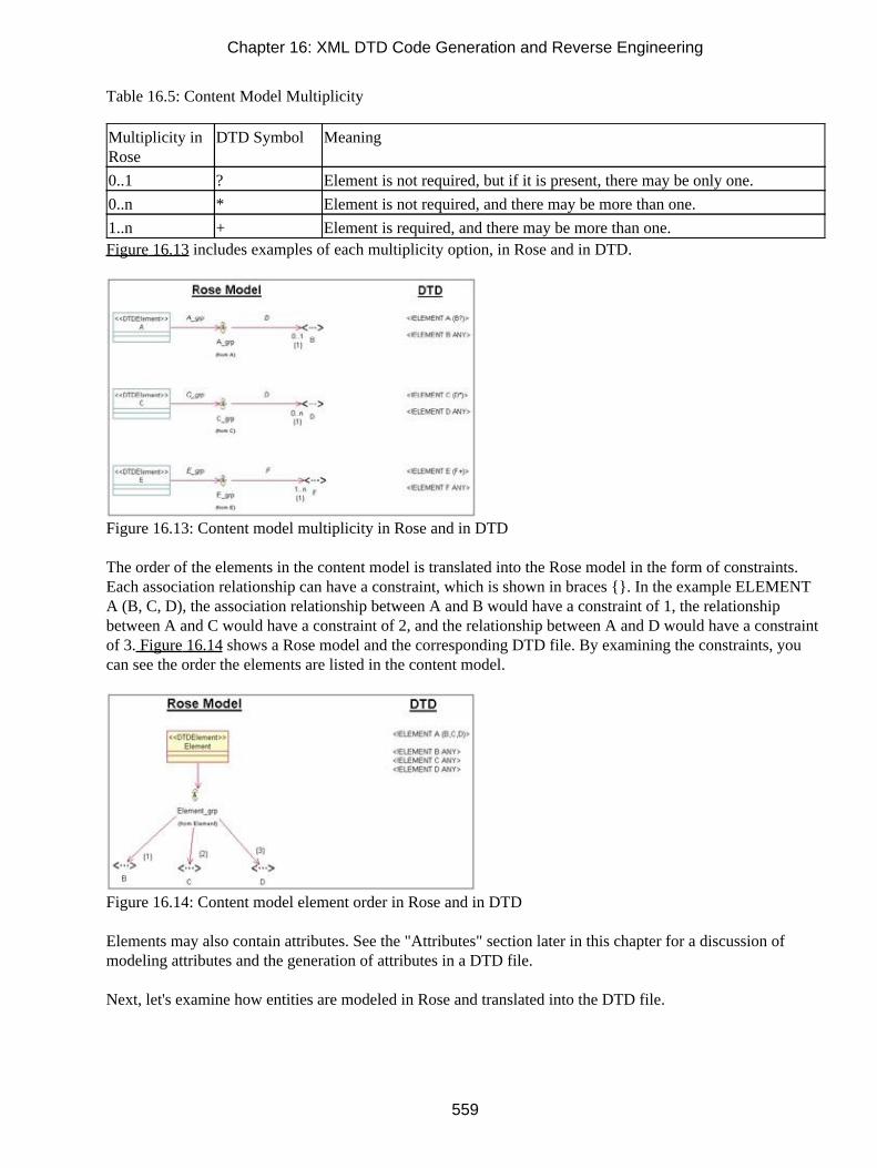
Table 16.5: Content Model Multiplicity
Multiplicity inRose
DTD Symbol Meaning
0..1 ? Element is not required, but if it is present, there may be only one.
0..n * Element is not required, and there may be more than one.
1..n + Element is required, and there may be more than one.Figure 16.13 includes examples of each multiplicity option, in Rose and in DTD.
Figure 16.13: Content model multiplicity in Rose and in DTD
The order of the elements in the content model is translated into the Rose model in the form of constraints.Each association relationship can have a constraint, which is shown in braces {}. In the example ELEMENTA (B, C, D), the association relationship between A and B would have a constraint of 1, the relationshipbetween A and C would have a constraint of 2, and the relationship between A and D would have a constraintof 3. Figure 16.14 shows a Rose model and the corresponding DTD file. By examining the constraints, youcan see the order the elements are listed in the content model.
Figure 16.14: Content model element order in Rose and in DTD
Elements may also contain attributes. See the "Attributes" section later in this chapter for a discussion ofmodeling attributes and the generation of attributes in a DTD file.
Next, let's examine how entities are modeled in Rose and translated into the DTD file.
Chapter 16: XML DTD Code Generation and Reverse Engineering
559

Entities
Like elements, entities are represented as classes in the Rose model. An entity is given the stereotype<<DTDEntity>>. Using the specification window shown in Figure 16.15, you can set the details of the entitythat will be generated in the DTD.
Figure 16.15: DTD entity specification window
If the entity is an internal entity, enter the entity value in the Value field in the specification window. Thevalue will appear in the generated DTD, as follows:
<!ENTITY Company "ACME DTD Files, Inc.">
If the entity is an external entity, select the External Entity check box and fill in the System ID, Public ID, andNotation Name fields:
System ID Enter the location of the entity in this field. For example, documentwithentity.xml.
Public ID Enter an alternate address for the entity in this field.
Notation Name If the external entity has a notation, enter the name of the notation here. Rose will includethe NDATA keyword in the generated DTD, similar to the following:
<!ENTITY MyVideo SYSTEM "C:\Videos\Vacation.vid" NDATA Video>
Whether the entity is internal or external, you can enter a comment into the DocComment field. Anything youenter in this field will appear as a comment in the generated DTD.
To create an entity:
1.
Chapter 16: XML DTD Code Generation and Reverse Engineering
560

Create a new class.
2. Assign the stereotype <<DTDEntity>> to the class.
3. Use the specification window to set the entity details as described above.
4. Create a notation if needed (see the following "Notations" section).
In Rose 2001A and 2002, you can use a special icon to represent an entity. Create an entity as describedabove. If the icon is not showing, right−click the class and select Options → Stereotype Display → Icon. TheEntity icon looks like this:
Notations
A notation is modeled as a class with a stereotype of <<DTDNotation>>. As with entities, the details for thenotation are set using the specification window (see Figure 16.16).
Figure 16.16: DTD notation pecification window
Using this window, you set the location of the application used to process the entity. You may also set analternate location using the Public ID field.
The notation is linked to the appropriate entity by a bidirectional association relationship. For example:
Chapter 16: XML DTD Code Generation and Reverse Engineering
561

Here is the DTD generated for the classes shown above.
<!ENTITY MyVideo SYSTEM "C:\Videos\Vacation.vid" NDATA Video><!NOTATION Video SYSTEM "C:\MyVideoPlayer.exe">
Note As long as the relationship exists, it does not matter what you enter in the Notation Name field on theentity specification window. If, for example, entity A is connected to notation N1 with an associationrelationship, and the Notation Name field on entity A's specification window refers to notation N2,notation N1 will still be used to generate the DTD.
To create a notation:
1. Create a new class.
2. Assign the stereotype <<DTDNotation>> to the class.
3. Use the specification window to set the notation details as described above.
Rose 2001A and 2002 provide an icon that can be used for notations. The Notation icon looks like this:
Attributes
An element's attributes are modeled as attributes within the element class. Each attribute has a data type andoptional default value. These can be set using the Field Specification window, as shown in Figure 16.17.
Chapter 16: XML DTD Code Generation and Reverse Engineering
562

Figure 16.17: DTD Field Specification window
The Type property is used to document the data type of the attribute. There are several options for the Typeproperty, including:
• CDATA, which means that the attribute is simple character data
• ENTITIES, which means that the attribute is a group of entities
• ENTITY, which means that the attribute is another entity
• ID, which means that the attribute is an element identifier
• IDREF, which means that the attribute is a reference to the ID of another element
• IDREFS, which means that the attribute is a group of IDREFs
• NMTOKEN, which means that the attribute is a name token attribute, which is a single word
• NMTOKENS, which means that the attribute is a collection of NMTOKENs
Chapter 16: XML DTD Code Generation and Reverse Engineering
563

The Default Value and Initial Value fields determine whether or not the attribute is required and what theinitial value in the attribute will be. Neither the initial value nor the default value is required. The possiblesettings include the following:
• The #REQUIRED default value suggests that the attribute is required to have a value on everyoccurrence of the element in the document. The initial value may or may not be entered if#REQUIRED is set. If an initial value is entered, it will be generated in the code as the initial valuefor the attribute.
• The #IMPLIED default value suggests that the attribute is not required and an initial value is notpresent.
• The #FIXED default value means that the attribute is not required, but if it is present, it must matchthe initial value.
• No default value means that an initial value should be entered. The attribute will not be required in thedocument, but if it is not present, the initial value will be assumed.
Reverse Engineering DTD
While generating a DTD can be useful, it may be even more valuable to reverse engineer existing DTD filesinto your Rose models. Many projects have a number of large and complex DTD structures, and Rose is anexcellent way of visualizing these structures. This can be particularly useful when trying to analyze thestructure of a complex DTD that you didn't create.
In this section, we'll discuss how to reverse engineer a DTD or group of DTD files into your Rose model.
1. To begin, create a new model or open an existing model.
2. Select Tools → XML_DTD → Reverse Engineer XML DTD.
3. Rose will display the XML/DTD Reverse Engineering dialog box, as shown in Figure 16.18.
4. Select the files you wish to reverse engineer in the upper−right portion of the screen, and press Add.
5. Select the files to reverse engineer from the list in the bottom portion of the screen, and press Reverse.
6. When finished, press Done.
Chapter 16: XML DTD Code Generation and Reverse Engineering
564

Rose will create a folder in the Logical view called NewPackage. All reverse−engineered items will be placedin this folder.
Figure 16.18: XML/DTD Reverse Engineering dialog box
Summary
In this chapter, we discussed how Rose can be used to model and generate an XML DTD file. We examinedhow DTD elements, attributes, entities, and content models can be structured in Rose, and how Rose cancreate the DTD file. Finally, we discussed the reverse engineering of a DTD file into a Rose model.
To review, these steps should be followed to generate a DTD:
1. Set the code−generation properties.
2. Select Tools → XML_DTD → Syntax Check.
3. Create a component to represent the DTD file, and map the classes to the DTD component.
4. Select the class(es) you wish to generate.
5. Select Tools → XML_DTD → Generate Code.
6. To view the generated DTD for a class, right−click the class on a diagram and select XML_DTD →Browse DTD Source.
The following steps should be followed to reverse engineer a DTD:
1.
Chapter 16: XML DTD Code Generation and Reverse Engineering
565

Select Tools → XML_DTD → Reverse Engineer XML DTD.
2. Select the files you wish to reverse engineer in the upper−right portion of the screen, and press Add.
3. Select the files to reverse engineer from the list in the bottom portion of the screen, and press Reverse.
4. When finished, press Done.
In the next chapter, we'll examine the creation and reverse engineering of CORBA elements using Rose.CORBA is an interface standard that helps components communicate, even if the components areprogrammed in different languages. Using Rose, you can design CORBA elements, set up relationshipsbetween the CORBA classes and classes in other languages, and generate the CORBA classes. Or, you canreverse engineer an application with CORBA elements to analyze the application architecture.
Chapter 16: XML DTD Code Generation and Reverse Engineering
566

Chapter 17: CORBA/IDL Code Generation andReverse EngineeringRounding out the powerful code−generation abilities of Rose is the CORBA/IDL add−in. From your Rosemodel, you can forward engineer code through the Component diagrams. In order to create the code, however,Rose will examine the properties of the classes—including the code−generation properties, attributes,operations, relationships, and packages—in the Logical view.
• Setting IDL code−generation properties
• Generating IDL code from your Rose model
• Mapping Rose elements to IDL constructs
• Reverse engineering IDL source code
CORBA/IDL Code−Generation Properties
CORBA (Common Object Request Broker Architecture) is a specification that supports the use of distributedobjects. Through the interface definition language (IDL), a developer can create language−independentinterfaces for components. The developer can then create components in multiple languages, and use IDL tohelp the objects communicate. The CORBA/IDL that is generated from your Rose model is controlled by aseries of code−generation property sets. Rose includes a property set for attributes, classes, dependencies,aggregations, module bodies, module specifications, operations, associations, subsystems, and for the overallproject.
You can view and set all of these properties by selecting Tools → Options, then selecting the CORBA tab.
567
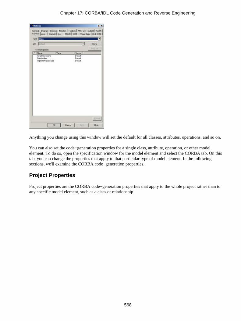
Anything you change using this window will set the default for all classes, attributes, operations, and so on.
You can also set the code−generation properties for a single class, attribute, operation, or other modelelement. To do so, open the specification window for the model element and select the CORBA tab. On thistab, you can change the properties that apply to that particular type of model element. In the followingsections, we'll examine the CORBA code−generation properties.
Project Properties
Project properties are the CORBA code−generation properties that apply to the whole project rather than toany specific model element, such as a class or relationship.
Chapter 17: CORBA/IDL Code Generation and Reverse Engineering
568

The options in this section include things like the default directory to use when generating code and themaximum number of errors that can occur during code generation. Each of the project properties is listed inTable 17.1 along with its purpose and default value.
Table 17.1: CORBA Code−Generation Project Properties
Property Purpose Default
CreateMissingDirectories Controls whether Rose should create directories tomirror the packages when generating code.
True
Editor Controls which editor to use to view and edit CORBAfiles.
Built−In (Uses abuilt−in CORBAeditor)
IncludePath Path used to resolve the location of .IDL files duringcode generation and reverse engineering.
Empty
StopOnError Controls whether Rose will stop generating code if itencounters an error.
True
PathSeparator Sets the character (such as the backslash) to separatepath elements.
<blank> (uses thedefault for theoperating system)
You can also set these properties through the Tools → CORBA → Project Specification menu item, as shownon the following page.
Chapter 17: CORBA/IDL Code Generation and Reverse Engineering
569

It does not matter whether you set the properties in the Tools → Options area or through the ProjectSpecification window. Changes you make in one area will be reflected in the other.
Class Properties
Class properties are the CORBA code−generation properties that apply specifically to classes. Most of theclass properties are set through the Class Specification window. There are a few properties, however, that canalso be set through the Tools → Options area, as shown below:
Table 17.2 lists the CORBA class properties on the Tools → Options window, their purposes, and theirdefault values.
Chapter 17: CORBA/IDL Code Generation and Reverse Engineering
570

Table 17.2: CORBA/IDL Code−Generation Class Properties
Property Purpose Default
ArrayDimensions Sets the dimensions of the array used in the classdefinition if the class is a typedef.
Empty
ImplementationType This value has different uses based on the class’sstereotype. If CORBAConstant, then the valueindicates the data type of the constant. IfCORBATypeDef, then the value indicates the datatype. If CORBAUnion, then the value is equivalent tothe switch type.
Empty
ConstValue If a CORBA constant is being generated, controls thevalue of the constant.
<blank>
The properties listed above apply to all types of CORBA classes. You can, however, set additional propertiesfor the different CORBA stereotypes supported by Rose.
When you first create a class and try to open its specification window, Rose will prompt you for the type ofclass to create:
In the Stereotype field, select from the following: Interface, CORBAConstant, CORBAEnum,CORBA−Exception, CORBANative, CORBAStruct, CORBATypedef, CORBAUnion, CORBAValue, orCORBACusomValue. Once you have selected a stereotype, the appropriate specification window will appear.
Interface Specification
On the interface specification window, you can set the following:
• Inherits From to set the parent class
• Attribute/Role Ordering to set the order in which attributes and roles will be generated in the code
• DocComment for comments that will be generated in the code
Chapter 17: CORBA/IDL Code Generation and Reverse Engineering
571

CORBAConstant Specification
On the constant specification window, you can set the following:
• Implementation Type to set the data type of the generated constant
• Constant Value to set the value of the generated constant
• DocComment for comments that will be generated in the code
CORBANative Specification
On the CORBANative specification window, you can set only the DocComment field, which is for commentsthat will be generated in the code.
Chapter 17: CORBA/IDL Code Generation and Reverse Engineering
572

CORBATypeDef Specification
On the typedef specification window, you can set the following:
• Implementation Type to set the data type of the generated typedef
• Array Dimensions to indicate that the typedef's declarator is an array and sets the dimensions of thearray
• DocComment for comments that will be generated in the code
CORBAUnion Specification
On the union specification window, you can set the following:
• Attribute/Role Ordering to set the order in which attributes and roles will be generated in the code
• Switch Type to set the switch type for case statements for the union
•
Chapter 17: CORBA/IDL Code Generation and Reverse Engineering
573

DocComment for comments that will be generated in the code
CORBAValue/CORBACustomValue
On the value specification window, you can set the following:
• Inherits From to set the parent class
• Attribute/Role Ordering to set the order in which attributes and roles will be generated in the code
• DocComment for comments that will be generated in the code
Other CORBA Stereotypes
On the specification window, you can set the following for other CORBA stereotypes (CORBA−Enum,CORBAException, and CORBAStruct):
•
Chapter 17: CORBA/IDL Code Generation and Reverse Engineering
574

Attribute/Role Ordering to set the order in which attributes and roles will be generated in the code
• DocComment for comments that will be generated in the code
Attribute Properties
Attribute properties are the CORBA properties that relate specifically to attributes. Using these properties, youcan control what is generated for each attribute in the model.
There are three places to set these properties. To set them for all attributes, select Tools → Options, then clickthe CORBA tab and select Attribute from the drop−down list box. To set them for only one attribute, selectthe CORBA tab on the attribute standard specification window, or open the CORBA specification windowand edit the properties there.
Chapter 17: CORBA/IDL Code Generation and Reverse Engineering
575

Table 17.3 lists the attribute properties, their purposes, and their default values.
Table 17.3: CORBA Code−Generation Attribute Properties
Property Purpose Default
ArrayDimensions Sets the array dimensions used for an exception,struct, or union when the BoundedRoleTypeassociation property is set to Array
<blank>
CaseSpecifier Sets the label of the case statement of a union <blank>
IsReadOnly Controls whether the generated attribute is read onlyFalse
Order Sets the order of generated attributes and roles <blank>As with classes, these attribute properties, as well as some additional properties, can be set using the CORBAspecification windows. The following shows the specification window for a CORBA attribute:
In the Name field, you can set or change the attribute's name. Whatever has been entered here will be used asthe attribute name in the generated code. In the Type field, enter the data type (long, char, etc.) of the attribute.The Visibility field allows you to set whether the attribute is public or private. The Bounded Role Type fieldis used for an exception, struct, or union and determines whether to create an array or a sequence attribute tosupport a relationship with bounded multiplicity. The Array Dimensions, Case Specifier, and Is Read Onlyfields are identical to the ArrayDimensions, CaseSpecifier, and IsReadOnly properties described in Table17.3. In the specification window, you can change either these fields or the properties.
Operation Properties
Operation properties are the CORBA code−generation properties that are specific to operations.
Chapter 17: CORBA/IDL Code Generation and Reverse Engineering
576

There are three places to set these properties. To set them for all operations, select Tools → Options, thenclick the CORBA tab and select Operation from the drop−down list box. To set them for only one operation,select the CORBA tab on the operation's standard specification window, or open the CORBA specificationwindow for the operation and edit the properties there.
Table 17.4 lists the operation code−generation properties, their purposes, and their default values.
Table 17.4: CORBA Code−Generation Operation Properties
Property Purpose Default
OperationIsOneWay Controls whether the one−way keyword will begenerated for the operation
False
Context Includes a context statement for the operation <blank>Additional properties can be set through the CORBA Operation Specification window, as shown on thefollowing page.
Chapter 17: CORBA/IDL Code Generation and Reverse Engineering
577

The Name, Return, and Arguments fields are used to set the operation's signature, including its parameters.The Visibility field controls whether the operation is public or private and will be directly used in codegeneration. The Raises field is used to set an exception class that will deal with exceptions for the operation.
Module Properties
Module properties are the properties that are related to the components in your Rose model. There are threeplaces to set these properties. To set them for all components, select Tools → Options, then click the CORBAtab and select Module Specification from the drop−down list box. To set them for only one component, selectthe CORBA tab on the component's standard specification window, or open the CORBA specificationwindow for the component and edit the properties there.
Table 17.5 lists the code−generation properties for components, their purposes, and their default values.
Table 17.5: CORBA Code−Generation Component Properties
Property Purpose Default
AdditionalIncludes Used to enter any additional #include statementsyou want to see in the code
<blank>
CmIdentification Used to enter codes that your configurationmanagement software can use
%X%%Q%%Z%%W%
CopyrightNotice Used to enter a copyright in the file <blank>
InclusionProtectionSymbol Sets the symbol that will be used to prevent a filefrom being included more than once
Auto Generate
You can also set these values using the CORBA specification window for the component. To open theCORBA specification window, right−click the component and select Open Specification.
Chapter 17: CORBA/IDL Code Generation and Reverse Engineering
578
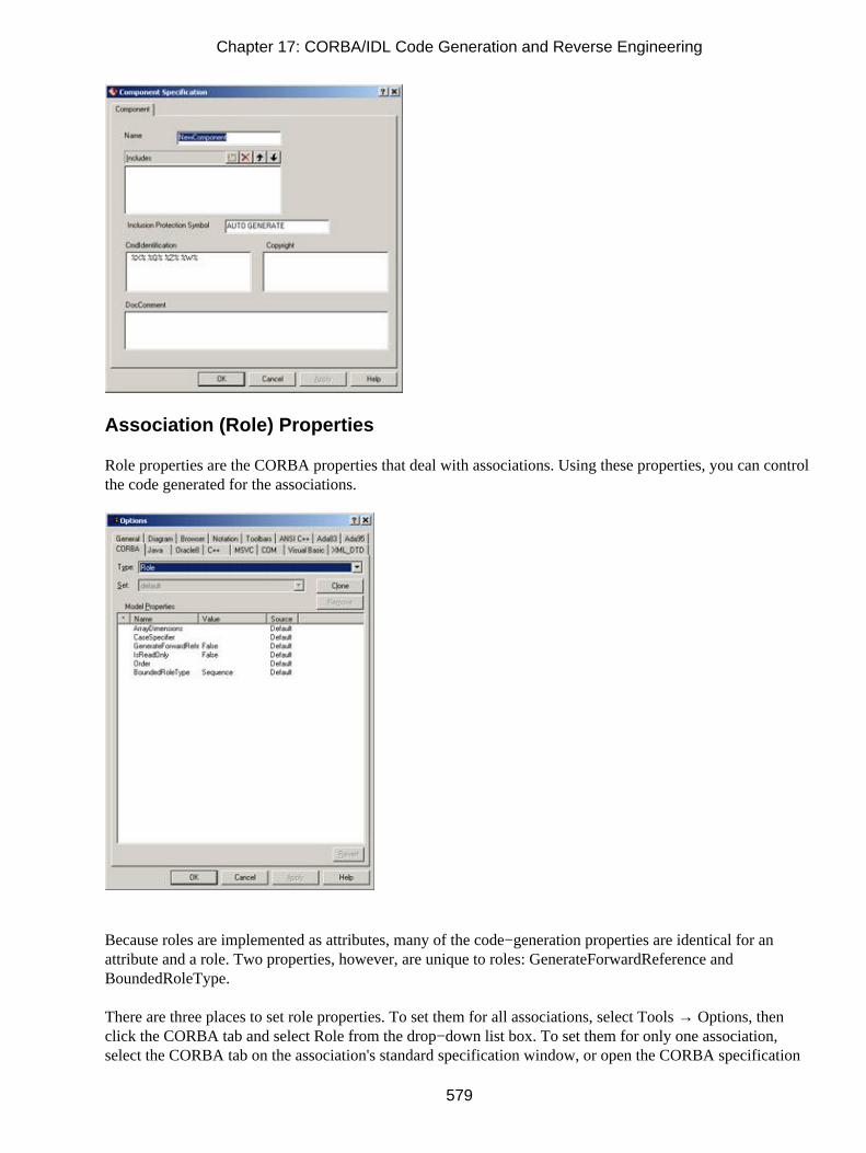
Association (Role) Properties
Role properties are the CORBA properties that deal with associations. Using these properties, you can controlthe code generated for the associations.
Because roles are implemented as attributes, many of the code−generation properties are identical for anattribute and a role. Two properties, however, are unique to roles: GenerateForwardReference andBoundedRoleType.
There are three places to set role properties. To set them for all associations, select Tools → Options, thenclick the CORBA tab and select Role from the drop−down list box. To set them for only one association,select the CORBA tab on the association's standard specification window, or open the CORBA specification
Chapter 17: CORBA/IDL Code Generation and Reverse Engineering
579

window for the association and edit the properties there.
Table 17.6 lists the code−generation properties for associations, their purposes, and their default values.
Table 17.6: CORBA Code−Generation Association Properties
Property Purpose Default
ArrayDimensions Sets the array dimensions used for an exception,struct, or union when the BoundedRoleTypeassociation property is set to Array
<blank>
CaseSpecifier Sets the label of the case statement of a union <blank>
GenerateForwardReference Controls whether a referenced interface is includedwith an #include statement or a forward reference
#include (False)
IsReadOnly Controls whether the generated attribute is read onlyFalse
Order Sets the order of attributes and roles generated <blank>
BoundedRoleType If the relationship multiplicity is greater than one,controls whether an array or sequence is used for thegenerated attribute
Sequence
These properties can also be set using the CORBA Attribute Specification window:
Dependency Properties
The dependency properties are the CORBA properties that control how dependency relationships aregenerated.
Chapter 17: CORBA/IDL Code Generation and Reverse Engineering
580

There are two places to set the dependency property. To set the property for all dependencies, select Tools →Options, then click the CORBA tab and select Dependency from the drop−down list box. To set the propertyfor only one dependency, select the CORBA tab on the dependency specification window and edit theproperties there. There is only one dependency property, GenerateForwardReference, which controls whethera referenced interface is included with an #include statement or a forward reference. By default, a #includestatement is used.
Generated Code
In the following sections, we'll examine the CORBA that is generated from the various types of modelelements. Rose will use the information you entered in the specification windows for the various modelelements when generating the CORBA/IDL.
Let's begin by looking at the code generated for a typical class.
Classes
A class in your object model will generate a single IDL file. The file that is generated will look something likethe following:
Interface TheClass{};
A great deal of additional information, such as configuration management statements, copyright notices, andinclude statements, will also be generated in the code. We'll look at a complete file in the following section,"Standard Code Generation."
Chapter 17: CORBA/IDL Code Generation and Reverse Engineering
581

All of the attributes, operations, and relationships of the class will be reflected in the generated code. Themajor elements generated for each class include:
• Class name
• Attributes
• Operations
• Relationships
• Documentation
When generating code, Rose will use the package structure you established in the Component view of yourmodel to generate the appropriate directories. A directory will be created for each package in the model.Within each of the directories Rose creates will be the files for the classes in that package.
Much of the information in your Rose model will be used directly when generating code. For example, theattributes, operations, relationships, and class name of each class will directly affect the code generated. Othermodel properties, such as the documentation entered for the class, will not directly affect the code. Theseproperties are created as comments in the generated code.
Table 17.7 lists the properties available in the class specification window and notes which of these propertieswill directly affect the IDL that is generated.
Table 17.7: Effect of Class Specifications on IDL
Property Effect on Code
Name Name in model will become class name
Type No effect
Stereotype No effect
Export Control No effect
Documentation Comment
Cardinality No effect
Space No effect
Persistence No effect
Concurrency No effect
Abstract No effect
Formal Arguments No effect
Operations Generated in code
Attributes Generated in code
Chapter 17: CORBA/IDL Code Generation and Reverse Engineering
582

Relationships Generated in codeStandard Code Generation
Let's look at the code generated for the following class.
The following IDL file was generated for the SampleClass:
//Source file: C:/corba/SampleClass.idl
#ifndef __SAMPLECLASS__DEFINED#define __SAMPLECLASS__DEFINED
/* CmIdentification %X% %Q% %Z% %W% */
#include "IncludedClass.idl"
interface SampleClass {};
#endif
Let's examine each piece of this file, one at a time.
Module Section
The module section contains some basic information about the class being generated. It includes the followingline:
//Source file: C:/corba/SampleClass.idl
This section includes comments that describe what class is being generated and where the IDL file is located.
Configuration Management Section
The configuration management section is provided to support integration with your configurationmanagement software. It includes the following lines:
/* CmIdentification %X% %Q% %Z% %W% */
This section of the file includes information about your configuration management settings. The properties onthe second line (%X% %Q% %Z% %W%) are the default configuration management settings. To change theconfiguration management settings, select Tools → Options from the menu. In the CORBA tab, select ModuleSpecification from the drop−down list box to display the module specification code−generation properties.You can use the CmIdentification property to change the default values on this second line. Using thisproperty, you can set the Change Management settings to a string that your configuration managementsoftware will recognize.
Some sample values you can place in this setting include:
•
Chapter 17: CORBA/IDL Code Generation and Reverse Engineering
583

$date, which inserts the date the code was generated
• $time, which inserts the time the code was generated
• $module, which inserts the component name
• $file, which inserts the component's file
Preprocessor Directives Section
The preprocessor directives include the following lines:
#ifndef __SAMPLECLASS_DEFINED#define __SAMPLECLASS_DEFINED
These lines are inserted into the code to prevent the file from being included more than once.
Includes Section
The includes section is the area of the generated code that shows any entries you added in theAdditionalIncludes code−generation property for the component and any entries you added in the Includessection of the specification window for the component.
The includes section for the SampleClass is as follows:
#include "IncludedClass.idl"
In this example, only one other class, called IncludedClass, was included.
Class Definition Section
This section contains information about the class itself, including the class name, its attributes, its operations,and its relationships. For the class example above, the definition section includes the following:
interface SampleClass {};
If you entered any documentation for the class using the documentation window or the documentation area ofthe class specification window, this documentation will be included as a comment in the code.
Code Generated for Different Types of CORBA/IDL
The code that is generated depends directly upon the stereotype (interface, union, const, etc.) of the class.Let's examine the code generated for the following class, with each of the different CORBA/IDL stereotypeoptions.
Chapter 17: CORBA/IDL Code Generation and Reverse Engineering
584

TypeDef Generation
If the class stereotype is set to CORBATypeDef, an interface will not be generated for the class. Instead, atypedef will be created. In the Implementation Type property on the Class Specification window, enter thedefinition that this typedef will be aliasing. The code generated for the SampleClass class looks like this:
//Source file: C:/corba/SampleClass.idl
#ifndef __SAMPLECLASS_DEFINED#define __SAMPLECLASS_DEFINED
/* CmIdentification %X% %Q% %Z% %W% */
#include "IncludedClass.idl"
typedef long SampleClass;
#endif
Enumeration Generation
The second CORBA type you can generate is an enumeration. If you select this option, Rose will use thekeyword "enum" in the generated file. The following is the code generated for the class above, but with thestereotype set to CORBAEnum.
//Source file: C:/corba/SampleClass.idl
#ifndef __SAMPLECLASS_DEFINED#define __SAMPLECLASS_DEFINED
/* CmIdentification %X% %Q% %Z% %W% */
#include "IncludedClass.idl"
enum SampleClass {
Attribute1,Attribute2};
#endif
Constant Generation
The third CORBA type that you can generate is a constant. In this case, Rose will include the keyword "const"in the generated IDL. To generate a constant, set the class stereotype to CORBAConstant. In the ClassSpecification window, set the Implementation Type field to the data type you wish to use and the ConstantValue field to the value of the constant.
Chapter 17: CORBA/IDL Code Generation and Reverse Engineering
585

The following is the file generated for SampleClass.
//Source file: C:/corba/SampleClass.idl
#ifndef __SAMPLECLASS_DEFINED#define __SAMPLECLASS_DEFINED
/* CmIdentification %X% %Q% %Z% %W% */
#include "IncludedClass.idl"
const long SampleClass = 4;
#endif
Exception Generation
The fourth CORBA type you can generate is an exception. If the class stereotype is set to CORBA−Exception,Rose will include the keyword "exception" in the code. Here is the file generated for SampleClass:
//Source file: C:/corba/SampleClass.idl
#ifndef __SAMPLECLASS_DEFINED#define __SAMPLECLASS_DEFINED
/* CmIdentification %X% %Q% %Z% %W% */
#include "IncludedClass.idl"
exception SampleClass { string Attribute1; string Attribute2;};
#endif
Structure Generation
Another CORBA type you can generate is a structure. Rose will include the "struct" keyword in the generatedfile if the stereotype of the class is set to CORBAStruct. The attributes of the class will appear as data
Chapter 17: CORBA/IDL Code Generation and Reverse Engineering
586

members in the generated file. The code generated for SampleClass is:
//Source file: C:/corba/SampleClass.idl
#ifndef __SAMPLECLASS_DEFINED#define __SAMPLECLASS_DEFINED
/* CmIdentification %X% %Q% %Z% %W% */
#include "IncludedClass.idl"
struct SampleClass { string Attribute1; string Attribute2;};
#endif
ValueType Generation
By setting the stereotype to CORBAValue, you can generate a valuetype. Here is the code generated for theSampleClass class with a stereotype of CORBAValue:
//Source file: C:/corba/SampleClass.idl
#ifndef __SAMPLECLASS_DEFINED#define __SAMPLECLASS_DEFINED
/* CmIdentification %X% %Q% %Z% %W% */
#include "IncludedClass.idl"
valuetype SampleClass { ; ;};
#endif
Union Generation
Finally, you can generate a union in CORBA by setting the class stereotype to CORBAUnion. The generatedcode looks like this:
//Source file: C:/corba/SampleClass.idl
#ifndef __SAMPLECLASS_DEFINED#define __SAMPLECLASS_DEFINED
/* CmIdentification %X% %Q% %Z% %W% */
#include "IncludedClass.idl"
union SampleClass switch(long) { case 1: string Attribute1; case 2: string Attribute2;
Chapter 17: CORBA/IDL Code Generation and Reverse Engineering
587

};
#endif
Before you can generate code, each of the attributes must have a case specifier. Open the specificationwindow for each of the attributes, and enter a value in the Case Specifier property. The values you enter willcontrol the case statements generated in the code. In the above example, the case specifier for Attribute1 is 1,and the specifier for Attribute2 is 2.
Attributes
As you may have noticed in the previous examples, attributes are generated in the code along with the class.This isn't true for all CORBA types, however. In this section, we'll examine the code generated for attributesfor each of the types: interface, typedef, enumeration, constant, exception, structure, and union. For each ofthese types, we'll take a look at what is generated for the following class:
Attributes Generated for an Interface
In an interface, all of the attributes of the class will appear in the generated code. For each attribute, Rose willinclude:
• Data type
• Documentation
This is the interface that is generated for the SampleClass class:
//Source file: C:/corba/SampleClass.idl
#ifndef __SAMPLECLASS_DEFINED#define __SAMPLECLASS_DEFINED
/* CmIdentification %X% %Q% %Z% %W% */
#include "IncludedClass.idl"
interface SampleClass { attribute string Attribute1; attribute string Attribute2;};
#endif
Chapter 17: CORBA/IDL Code Generation and Reverse Engineering
588

Attributes Generated for a TypeDef
If the class stereotype is set to CORBATypeDef, attributes do not appear in the generated code.
Attributes Generated for an Enumeration
With an enumeration, Rose will place the attributes in the generated code. However, Rose will ignore the datatypes, default values, and other specifications of the attribute. Here is the enumeration generated for theSampleClass class:
//Source file: C:/corba/SampleClass.idl
#ifndef __SAMPLECLASS_DEFINED#define __SAMPLECLASS_DEFINED
/* CmIdentification %X% %Q% %Z% %W% */
#include "IncludedClass.idl"
enum SampleClass {
Attribute1, Attribute2};
#endif
Attributes Generated for a Constant
If the class stereotype is set to CORBAConstant, attributes do not appear in the generated code.
Attributes Generated for an Exception
If the class stereotype is set to CORBAException, all attributes of the class will be included in the code. Foreach attribute, the code will include:
• Data type
• Documentation
Here is the code generated for SampleClass when the stereotype is set to CORBAException:
//Source file: C:/corba/SampleClass.idl
#ifndef __SAMPLECLASS_DEFINED#define __SAMPLECLASS_DEFINED
/* CmIdentification %X% %Q% %Z% %W% */
#include "IncludedClass.idl"
exception SampleClass {
Chapter 17: CORBA/IDL Code Generation and Reverse Engineering
589

string Attribute1; string Attribute2;};
#endif
Attributes Generated for a Structure
If the class stereotype is set to CORBAStruct, all attributes of the class will be included in the code. For eachattribute, the code will include:
• Data type
• Documentation
Here is the code generated when the SampleClass stereotype is set to CORBAStruct:
//Source file: C:/corba/SampleClass.idl
#ifndef __SAMPLECLASS_DEFINED#define __SAMPLECLASS_DEFINED
/* CmIdentification %X% %Q% %Z% %W% */
#include "IncludedClass.idl"
struct SampleClass {string Attribute1;string Attribute2;};
#endif
Attributes Generated for a Union
If the class stereotype is set to CORBAUnion, the attributes of the class will appear as case statements in theunion. Here is the code generated for SampleClass:
//Source file: C:/corba/SampleClass.idl
#ifndef __SAMPLECLASS_DEFINED#define __SAMPLECLASS_DEFINED
/* CmIdentification %X% %Q% %Z% %W% */
#include "IncludedClass.idl"
union SampleClass switch(long) {case 1: string Attribute1;case 2: string Attribute2;};
Chapter 17: CORBA/IDL Code Generation and Reverse Engineering
590

#endif
The values used in the case statements are set by the values you enter in the Case Specifier field in eachattribute's specification window.
Operations
The operations you define in your Rose model will appear in the generated IDL. Like attributes, though,operations are included only for certain CORBA types. In this section, we'll take a look at the code generatedfor operations of the following class:
We'll examine how the code is generated as the stereotype of the class changes.
Operations Generated for an Interface
With an interface, all of the operations for the class will appear in the generated code, along with theirparameters, parameter data types, and return type. For the SampleClass class, the following interface wasgenerated:
//Source file: C:/corba/SampleClass.idl
#ifndef __SAMPLECLASS_DEFINED#define __SAMPLECLASS_DEFINED
/* CmIdentification %X% %Q% %Z% %W% */
#include "IncludedClass.idl"
interface SampleClass {/* @roseuid 39B5C1A0006A */string Operation1 ();
};
#endif
Operations Generated for Other CORBA/IDL Types
Operations are shown in the generated IDL only for interfaces. If the class stereotype is a typedef,enumeration, const, exception, struct, or union, operations will not be generated in the code.
Bidirectional Associations
To support bidirectional associations, Rose will generate attributes in the code. Each of the classes in therelationship will contain an attribute to support the association. The names of the generated attributes will becontrolled by the role names on the association relationship. You must enter role names before you cangenerate code.
Chapter 17: CORBA/IDL Code Generation and Reverse Engineering
591

The code generated for the two classes shown above will resemble the following:
interface Class_A {attribute Class_B Class_B_Role;};
and
interface Class_B {attribute Class_A Class_A_Role;};
As you can see, Rose will automatically generate attributes on both sides of the bidirectional associationrelationship. With the Class_B_Role attribute, Class_A can easily access Class_B. Using the Class_A_Roleattribute, Class_B can easily access Class_A.
The full code generated for Class_A is:
//Source file: C:/corba/Class_A.idl
#ifndef CLASS_A_DEFINED#define CLASS_A_DEFINED
/* CmIdentification %X% %Q% %Z% %W% */
#include "Class_B.idl"
interface Class_A { attribute Class_B Class_B_Role;};
As you can see, Class_A now includes an attribute of type Class_B. Class_B will also include an attribute oftype Class_A. These two attributes support the relationship between Class_A and Class_B.
Bidirectional Associations Generated for a TypeDef
If the stereotype for Class_A is set to CORBATypeDef, a Class_B attribute will not be included in the codefor Class_A. However, an #include statement will be added to the code in Class_A, as follows:
Chapter 17: CORBA/IDL Code Generation and Reverse Engineering
592

#include "Class_B.idl"
Bidirectional Associations Generated for an Enumeration
If the stereotype of Class_A is set to CORBAEnum, an include statement for Class_B.IDL will be included inthe code. An attribute will not, however, be generated in Class_A. The code for Class_A looks like this:
//Source file: C:/corba/Class_A.idl
#ifndef CLASS_A_DEFINED#define CLASS_A_DEFINED
/* CmIdentification %X% %Q% %Z% %W% */
#include "Class_B.idl"
enum Class_A {
};
#endif
Bidirectional Associations Generated for a Constant
If Class_A is a constant, it will have an include statement for Class_B, but will not have an attribute thatsupports the relationship. Here is the code generated for Class_A:
//Source file: C:/corba/Class_A.idl
#ifndef CLASS_A_DEFINED#define CLASS_A_DEFINED
/* CmIdentification %X% %Q% %Z% %W% */
#include "Class_B.idl"
const long Class_A = 4;
#endif
Bidirectional Associations Generated for an Exception
If Class_A is an exception, an attribute of type Class_B will be generated inside it. Here is the code generatedfor Class_A:
//Source file: C:/corba/Class_A.idl
#ifndef CLASS_A_DEFINED#define CLASS_A_DEFINED
/* CmIdentification %X% %Q% %Z% %W% */
#include "Class_B.idl"
exception Class_A {
Chapter 17: CORBA/IDL Code Generation and Reverse Engineering
593

Class_B Class_B_Role;};
#endif
Bidirectional Associations Generated for a Structure
If the stereotype of Class_A is CORBAStruct, an attribute will be created inside Class_A when you generatethe IDL.
The code for Class_A is as follows:
//Source file: C:/corba/Class_A.idl
#ifndef CLASS_A_DEFINED#define CLASS_A_DEFINED
/* CmIdentification %X% %Q% %Z% %W% */
#include "Class_B.idl"
struct Class_A {Class_B Class_B_Role;};
#endif
Bidirectional Associations Generated for a Union
If the stereotype for Class_A is set to CORBAUnion, the generated code will have an include statement forClass_B, and will include an instance of Class_B within the switch statement. Here is the code generated forClass_A:
//Source file: C:/corba/Class_A.idl
#ifndef CLASS_A_DEFINED#define CLASS_A_DEFINED
/* CmIdentification %X% %Q% %Z% %W% */
#include "Class_B.idl"
union Class_A switch() {case 1: Class_B Class_B_Role;};
#endif
Note that the attribute generated from the association needs a case specifier, as do the other attributes ofClass_A. The case specifier can be set using the Case Specifier Role code−generation property for therelationship.
Chapter 17: CORBA/IDL Code Generation and Reverse Engineering
594

Unidirectional Associations
As with bidirectional associations, Rose will generate attributes to support unidirectional associations. With aunidirectional association, however, an attribute is generated at only one end of the relationship.
For the Class_A and Class_B classes above, code similar to the following would be created:
interface Class_A {attribute Class_B Class_B_Role;};
and
Interface Class_B{};
As you can see, Rose will generate a private attribute for the relationship at only one end of the association.Specifically, it will generate an attribute in the client class, but not in the supplier class.
For each of the other CORBA types (typedef, enumeration, const, exception, struct, or union), Rose willgenerate code as shown in the bidirectional associations sections above. The only difference with aunidirectional association is that the attribute will be created on only one side of the relationship.
Note that the multiplicity here is one to one. Let's take a look at how code is affected when the multiplicitysettings are changed.
Associations with a Multiplicity of One to Many
In a one−to−one relationship, Rose can simply create the appropriate attributes to support the association.With a one−to−many relationship, however, one class must contain a set of the other class.
To begin, let's look at an example.
Chapter 17: CORBA/IDL Code Generation and Reverse Engineering
595

In this case, we have a one−to−many relationship. As we saw earlier, Class_B can generate an attribute that issimply a pointer to Class_A, but a simple pointer attribute in the Class_A class won't be enough. Instead, theattribute generated in Class_A must use some sort of container class as its data type. In IDL, there are twocontainer classes you can use: a sequence or an array. By default, Rose will use a sequence.
For this example, Rose will generate code similar to the following:
interface Class_A { typedef sequence <Class_B> Class_B_Roledef;
attribute Class_B_Roledef Class_B_Role;};
and
interface Class_B { attribute Class_A Class_A_Role;};
As you can see, Class_B includes a simple pointer to Class_A, as we saw earlier. However, a container classwas used in Class_A when generating the Class_B attribute.
The full code generated for Class_A is:
//Source file: C:/corba/Class_A.idl
#ifndef CLASS_A_DEFINED#define CLASS_A_DEFINED
/* CmIdentification %X% %Q% %Z% %W% */
#include "Class_B.idl"
interface Class_A { typedef sequence <Class_B> Class_B_Roledef;
attribute Class_B_Roledef Class_B_Role;};
#endif
Chapter 17: CORBA/IDL Code Generation and Reverse Engineering
596

Again, Rose will use a sequence as the default container class. To use an array instead, open the relationshipspecification and change the BoundedRoleType property to Array. To use an array for all relationships with amultiplicity greater than one, select Tools → Options from the menu. On the CORBA tab, select Role fromthe drop−down list box and change the value in the BoundedRoleType property to Array.
One−to−Many Associations Generated for a TypeDef
If the stereotype of Class_A is CORBATypeDef, an #include statement will be added to the code, but anattribute will not be generated in Class_A to support the relationship with Class_B. The code generated forClass_A is as follows:
//Source file: C:/corba/Class_A.idl
#ifndef CLASS_A_DEFINED#define CLASS_A_DEFINED
/* CmIdentification %X% %Q% %Z% %W% */
#include "Class_B.idl"
typedef sequence <Class_B> Class_A;
#endif
One−to−Many Associations Generated for an Enumeration
As with a typedef, Rose will not generate attributes to support the relationship if Class_A is an enumeration.There will, however, be an #include statement in the code generated for Class_A. The code for Class_A is asfollows:
//Source file: C:/corba/Class_A.idl
#ifndef CLASS_A_DEFINED#define CLASS_A_DEFINED
/* CmIdentification %X% %Q% %Z% %W% */
#include "Class_B.idl"
enum Class_A {
};
#endif
One−to−Many Associations Generated for a Constant
If Class_A is a constant, it will have an #include statement for Class_B, but will not have an attribute for therelationship. The code for Class_A is shown below:
//Source file: C:/corba/Class_A.idl
#ifndef CLASS_A_DEFINED
Chapter 17: CORBA/IDL Code Generation and Reverse Engineering
597

#define CLASS_A_DEFINED
/* CmIdentification %X% %Q% %Z% %W% */
#include "Class_B.idl"
const long Class_A = 4;
#endif
One−to−Many Associations Generated for an Exception
If Class_A is an exception, an attribute will be created inside it to support the relationship to Class_B. In aone−to−many relationship, Rose will use a container class when generating this attribute. By default, as withone−to−many relationships between interfaces, Rose will use a sequence as a container. You can change thecontainer class to use an array by changing the BoundedRoleType role property to Array.
The following code is generated for Class_A when its stereotype is set to CORBAException and Class_A hasa one−to−many relationship with Class_B.
//Source file: C:/corba/Class_A.idl
#ifndef CLASS_A_DEFINED#define CLASS_A_DEFINED
/* CmIdentification %X% %Q% %Z% %W% */
#include "Class_B.idl"
exception Class_A { sequence <Class_B> Class_B_Role;};
#endif
One−to−Many Associations Generated for a Structure
When the stereotype of Class_A is set to CORBAStruct, and Class_A has a one−to−many relationship withClass_B, an attribute will be created in Class_A to support that relationship. As with the other one−to−manyrelationships, Rose will use a container class when creating the attribute. By default, a sequence is used. Touse an array instead, change the BoundedRoleType role property.
The following is the code generated for Class_A:
//Source file: C:/corba/Class_A.idl
#ifndef CLASS_A_DEFINED#define CLASS_A_DEFINED
/* CmIdentification %X% %Q% %Z% %W% */
#include "Class_B.idl"
struct Class_A {
Chapter 17: CORBA/IDL Code Generation and Reverse Engineering
598

sequence <Class_B> Class_B_Role;};
#endif
One−to−Many Associations Generated for a Union
If Class_A is a union, both an #include statement and an attribute will be generated in Class_A to support therelationship with Class_B. The code for Class_A is as follows:
//Source file: C:/corba/Class_A.idl
#ifndef CLASS_A_DEFINED#define CLASS_A_DEFINED
/* CmIdentification %X% %Q% %Z% %W% */
#include "Class_B.idl"union Class_A switch() { case 1: sequence <Class_B> Class_B_Role;};
#endif
#endif
Associations with a Multiplicity of Many to Many
The code generated here is similar to that created for a one−to−many relationship. With a many−to−manyrelationship, however, Rose will generate container classes on both ends of the relationship.
Let's look at the code generated for the following relationship:
In this situation, container classes are used at both ends of the relationship. The code that is generated willlook something like the following:
interface Class_A { typedef sequence <Class_B> Class_B_Role_def;
Chapter 17: CORBA/IDL Code Generation and Reverse Engineering
599

attribute Class_B_Role_def Class_B_Role;};
and
interface Class_B { typedef sequence <Class_A> Class_A_Role_def;
attribute Class_A_Role_def Class_A_Role;};
The complete code generated for Class_A will look exactly as it did in the previous section. The difference isthat now the code for Class_B will also include an attribute with a container type. The code generated forClass_B is:
//Source file: C:/corba/Class_B.idl
#ifndef CLASS_B_DEFINED#define CLASS_B_DEFINED
/* CmIdentification %X% %Q% %Z% %W% */
#include "Class_A.idl"
interface Class_B { typedef sequence <Class_A> Class_A_Roledef; attribute Class_A_Roledef Class_A_Role;};
#endif
Many−to−Many Associations Generated for Other CORBA Types
The code generated for a many−to−many relationship with other CORBA types will look exactly like the codewe examined in the previous section. The only difference is that Class_B will now contain an attribute of typeClass_A.
Associations with Bounded Multiplicity
An association with bounded multiplicity is one that has a range of numbers at one end of the relationship. Forexample, the following relationship has bounded multiplicity:
Chapter 17: CORBA/IDL Code Generation and Reverse Engineering
600

In this example, each instance of Class_A is related to 2–4 instances of Class_B.
The two types of bounded relationships we will examine are bounded associations and fixed associations.Bounded associations have a multiplicity range, like 2..4. Fixed associations have a single number in themultiplicity. For example, a multiplicity of 4 is fixed.
For the example above, Rose will generate something like this:
interface Class_A {typedef sequence <Class_B, 4> Class_B_Roledef;attribute Class_B_Roledef Class_B_Role;};
and
interface Class_B {attribute Class_A Class_A_Role;};
As with one−to−many and many−to−many relationships, Rose uses container classes when generating theattributes. By default, Rose will use a sequence, but you can change the container to an array. You make thischange by selecting the CORBA A or CORBA B tab of the relationship specification and then changing theBoundedRoleType property to Array. To change the container class for all bounded relationships, select Tools→ Options from the menu. On the CORBA tab, select Role from the drop−down list box. Change the value inthe BoundedRoleType property to Array.
Bounded Associations Generated for an Exception
If Class_A is an exception, the code generated will include an attribute to support the relationship to Class_B.In this case, a simplified version of the generated code will look something like this:
Exception Class_A{sequence <Class_B, 4> Class_B_Role;};
As with other relationships where the multiplicity is greater than one, Rose will use a sequence as the defaultcontainer class. To use an array, change the BoundedRoleType property to Array.
Chapter 17: CORBA/IDL Code Generation and Reverse Engineering
601

Bounded Associations Generated for a Structure
The code generated for a structure will include an attribute to support the relationship between Class_A andClass_B. A simplified version of the code is as follows:
Struct Class_A{sequence <Class_B, 4> Class_B_Role;};
Again, a sequence is the default container. To use an array instead, you can change the Bounded−RoleTyperole property to Array.
Bounded Associations Generated for a Union
If Class_A is a union and has a bounded association with Class_B, an attribute will be created in Class_A tosupport the relationship. By default, the container used in this attribute is a sequence. Here, we have asequence length of 4.
union Class_A switch(int) {case 3: sequence <Class_B, 4> Class_B_Role;};
Bounded Associations Generated for Other CORBA/IDL Types
If types other than interface, exception, structure, or union are used, no attributes will be generated to supportthe relationship. However, #include statements will be placed in both Class_A and Class_B.
Reflexive Associations
A reflexive association is treated much the same as an association between two classes. For the followingsituation:
code similar to this is generated:
interface Class_A { typedef sequence <Class_A> RoleAdef; attribute Class_A RoleB; attribute RoleAdef RoleA;};
The first two lines support the 0..* end of the relationship. They include a container class that will support thismultiplicity. The third line supports the end of the relationship with a multiplicity of one.
The full code generated for Class_A is as follows:
Chapter 17: CORBA/IDL Code Generation and Reverse Engineering
602

//Source file: C:/corba/Class_A.idl
#ifndef CLASS_A_DEFINED#define CLASS_A_DEFINED
/* CmIdentification %X% %Q% %Z% %W% */
interface Class_A { typedef sequence <Class_A> RoleAdef;
attribute Class_A RoleB; attribute RoleAdef RoleA;};
#endif
Reflexive Associations Generated for an Exception
If Class_A is stereotyped as an exception, only one attribute will be generated for the relationship. In thisexample, an attribute is generated to support the one end of the one−to−many relationship. The code forClass_A is shown below:
//Source file: C:/corba/Class_A.idl#ifndef CLASS_A_DEFINED#define CLASS_A_DEFINED/* CmIdentification %X% %Q% %Z% %W% */exception Class_A {Class_A RoleB;};#endif
Reflexive Associations Generated for a Structure
If Class_A is a structure, an attribute will be created inside of it to support the reflexive relationship. If therelationship looks like the previous reflexive association, then the following code will be generated.
//Source file: C:/corba/Class_A.idl
#ifndef __CLASS_A_DEFINED#define __CLASS_A_DEFINED
/* CmIdentification %X% %Q% %Z% %W% */
struct Class_A {Class_A RoleB;};
#endif
Reflexive Associations Generated for a Union
If Class_A is a union, a single attribute will be created inside the class to support the reflexive relationship.The following code is generated for Class_A:
Chapter 17: CORBA/IDL Code Generation and Reverse Engineering
603

//Source file: C:/corba/Class_A.idl
#ifndef CLASS_A_DEFINED#define CLASS_A_DEFINED
/* CmIdentification %X% %Q% %Z% %W% */
union Class_A switch() { case 2: Class_A RoleB;};
#endif
Reflexive Associations Generated for Other CORBA/IDL Types
Because attributes are not generated for a typedef, enumeration, or constant, reflexive associations with thesetypes will not be reflected in the code.
Aggregations
When generating CORBA/IDL, associations and aggregations are treated the same. All of the considerationswe've discussed so far (the multiplicity, whether the relationship is unidirectional or bidirectional, andwhether or not the relationship is reflexive) apply the same to aggregations as they do to associations. This istrue for any of the CORBA types (interface, typedef, enumeration, constant, exception, structure, or union).
For information about how unidirectional aggregations, aggregations with various multiplicity indicators, andreflexive aggregations are generated, please see the corresponding sections on associations.
Dependency Relationships
With a dependency relationship, attributes are not created. If there is a dependency between Class_A andClass_B, attributes will be created in neither Class_A nor Class_B.
The code that is generated will look something like the following:
Interface Class_A{};
and
Chapter 17: CORBA/IDL Code Generation and Reverse Engineering
604

Interface Class_B{};
Rose will place only one reference to Class_B—an include statement for Class_B.IDL—inside of Class_A.Class_A will not be referenced in Class_B at all.
Because no attributes are generated for a dependency, an attribute will not be created for any of the CORBAtypes (interface, typedef, enumeration, constant, exception, structure, or union).
Generalization Relationships
A generalization relationship in UML becomes an inheritance relationship in IDL. In your Rose model, aninheritance relationship is shown as follows:
For this type of relationship, Rose will generate something that looks like this:
Interface Parent{};
and
Interface Child : Parent{};
Let's look at the actual code that is generated. In the code for the parent class, there is no mention of the childclass. This helps keep the parent generic; many classes can therefore inherit from it without affecting its code.
In the child class, the code is generated to support its inheritance from the parent class. The code for the childclass is as follows:
//Source file: C:/corba/Child.idl
#ifndef __CHILD_DEFINED#define __CHILD_DEFINED
/* CmIdentification %X% %Q% %Z% %W% */
Chapter 17: CORBA/IDL Code Generation and Reverse Engineering
605

#include "Parent.idl"
interface Child : Parent {};
#endif
Generalizations Generated for a TypeDef
If the child class is a typedef, an #include statement will appear in the generated code for the child, but aninheritance relationship will not be shown in the code. The IDL for the child class is as follows:
//Source file: C:/corba/Child.idl
#ifndef __CHILD_DEFINED#define __CHILD_DEFINED
/* CmIdentification %X% %Q% %Z% %W% */
#include "Parent.idl"
typedef Child;
#endif
Generalizations Generated for an Enumeration
The same is true for an enumeration. Although an #include statement is generated, the inheritance relationshipitself is not represented in the code. In this case, the generated code looks like this:
//Source file: C:/corba/Child.idl
#ifndef __CHILD_DEFINED#define __CHILD_DEFINED
/* CmIdentification %X% %Q% %Z% %W% */
#include "Parent.idl"
enum Child {
};
#endif
Generalizations Generated for a Constant
As with a typedef or enumeration, a generalization relationship will not be directly implemented in code witha constant. An #include statement will be generated to reference the parent. The code for this example lookslike this:
//Source file: C:/corba/Child.idl
Chapter 17: CORBA/IDL Code Generation and Reverse Engineering
606

#ifndef __CHILD_DEFINED#define __CHILD_DEFINED
/* CmIdentification %X% %Q% %Z% %W% */
#include "Parent.idl"
const long Child = 4;
#endif
Generalizations Generated for an Exception
Inheritance is not supported with an exception. Therefore, as in the other cases, an #include statement will begenerated, but the generalization itself will not be reflected in the code. The IDL for this situation looks likethis:
//Source file: C:/corba/Child.idl
#ifndef __CHILD_DEFINED#define __CHILD_DEFINED
/* CmIdentification %X% %Q% %Z% %W% */
#include "Parent.idl"
exception Child {};
#endif
Generalizations Generated for a Structure
As with the other CORBA types, inheritance is not supported with a structure. An #include statement will beincluded to reference the parent, but the inheritance relationship will not be reflected in the code. The IDLgenerated for a generalization with a structure is as follows:
//Source file: C:/corba/Child.idl
#ifndef __CHILD_DEFINED#define __CHILD_DEFINED
/* CmIdentification %X% %Q% %Z% %W% */
#include "Parent.idl"
struct Child {};
#endif
Chapter 17: CORBA/IDL Code Generation and Reverse Engineering
607

Generalizations Generated for a Union
A generalization with a union is much the same as a generalization with all other CORBA types, exceptinterface. Because generalizations are not supported with a union, they will not appear in the generated code.The only reference to the parent in the generated code is an #include statement. The code looks like this:
//Source file: C:/corba/Child.idl
#ifndef __CHILD_DEFINED#define __CHILD_DEFINED
/* CmIdentification %X% %Q% %Z% %W% */
#include "Parent.idl"
union Child switch() {};
#endif
Reverse Engineering CORBA Source Code
You can reverse engineer CORBA source code into your Rose model. Each .idl file that you reverse engineerwill be modeled as a component in Rose. The classes, relationships, and other elements in the file will appearin the Logical view.
To begin the process, first select Tools → CORBA → Project Specification. In the Directories field, select thedirectories that contain the source code you wish to reverse engineer.
Once you complete this step, select Tools → CORBA → Reverse Engineer CORBA. In thereverse−engineering window, select the file(s) you wish to reverse engineer and press Add. Once all files havebeen added to the lower window, select the file(s) in the lower window to reverse engineer and press Reverse.If any errors occur during the reverse−engineering process, a note will be entered in the log window.
Chapter 17: CORBA/IDL Code Generation and Reverse Engineering
608

Elements in the .idl files will be mapped to Rose elements using the mapping described throughout thischapter.
Summary
In this chapter, we examined how the different types of elements in your Rose model are generated inCORBA /IDL. We looked at the different code−generation properties for classes, packages, attributes,operations, associations, aggregations, and other model elements, and discussed how these properties affectthe generated code.
Again, the steps needed to generate code are:
1. Set the CORBA/IDL code−generation properties.
2. Select the class(es) or component(s) to generate on a Class or Component diagram.
3. Select Tools → CORBA → Generate CORBA.
Once these steps are complete, you will have CORBA/IDL files that were generated from your model. Toreverse engineer CORBA source code, select Tools → CORBA → Reverse Engineer CORBA. Select the filesto reverse engineer, and Rose will load information from the code into the model.
So far, we've examined how Rose can be used to model an application. An important aspect of manyapplications, however, is the database. In the next chapter, we'll take a look at how Rose can be used for datamodeling. Through the powerful Data Modeler feature within Rose, you can model your database as well asyour application, and ensure that your data model and object model are consistent with one another.
Chapter 17: CORBA/IDL Code Generation and Reverse Engineering
609

Chapter 18: Rose Data ModelerSo far, we've focused on modeling the application itself—creating the Use Case diagrams, Interactiondiagrams, Class diagrams, and other artifacts needed to really understand how the system works. An essentialelement to nearly every system, however, is some form of persistent storage, typically a database.
Using Rose, you can model not only the application, but also the database or databases that support theapplication. Rose 2001, 2001A, and 2002 support the data−modeling notation that has been incorporated intoUML.
• Comparing object models and data models
• Creating a data model
• Adding logic to a data model
• Modeling databases, schemas, tables, fields, stored procedures, triggers, and more
• Modeling primary keys, foreign keys, and entity relationships
• Modeling views
• Generating an object model from a data model
• Generating a data model from an object model
• Creating the database from a data model
• Reverse engineering a database into a data model
Object Models and Data Models
An object model is used for all of the pieces of the application that we have discussed so far—the classes,attributes, operations, relationships, components, and other constructs—except for the data. The primaryemphasis of an object model is on memory—what objects will be created in memory, how will these objectscommunicate, and what is each object responsible for doing? The focus of the data model is, as the nameimplies, the database rather than the application.
While object modeling is concerned with memory efficiency, data modeling is more concerned with databaseefficiency. Table 18.1 lists some of the differences in perspective between the data model and the object
610
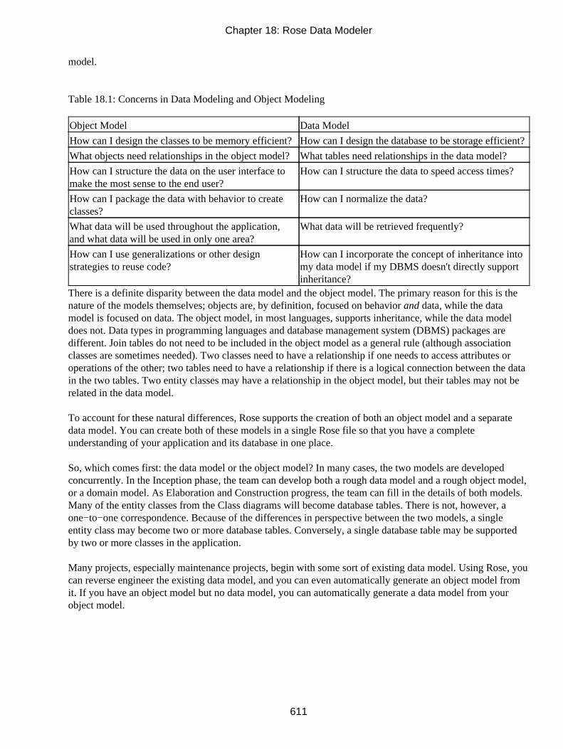
model.
Table 18.1: Concerns in Data Modeling and Object Modeling
Object Model Data Model
How can I design the classes to be memory efficient?How can I design the database to be storage efficient?
What objects need relationships in the object model?What tables need relationships in the data model?
How can I structure the data on the user interface tomake the most sense to the end user?
How can I structure the data to speed access times?
How can I package the data with behavior to createclasses?
How can I normalize the data?
What data will be used throughout the application,and what data will be used in only one area?
What data will be retrieved frequently?
How can I use generalizations or other designstrategies to reuse code?
How can I incorporate the concept of inheritance intomy data model if my DBMS doesn't directly supportinheritance?
There is a definite disparity between the data model and the object model. The primary reason for this is thenature of the models themselves; objects are, by definition, focused on behavior and data, while the datamodel is focused on data. The object model, in most languages, supports inheritance, while the data modeldoes not. Data types in programming languages and database management system (DBMS) packages aredifferent. Join tables do not need to be included in the object model as a general rule (although associationclasses are sometimes needed). Two classes need to have a relationship if one needs to access attributes oroperations of the other; two tables need to have a relationship if there is a logical connection between the datain the two tables. Two entity classes may have a relationship in the object model, but their tables may not berelated in the data model.
To account for these natural differences, Rose supports the creation of both an object model and a separatedata model. You can create both of these models in a single Rose file so that you have a completeunderstanding of your application and its database in one place.
So, which comes first: the data model or the object model? In many cases, the two models are developedconcurrently. In the Inception phase, the team can develop both a rough data model and a rough object model,or a domain model. As Elaboration and Construction progress, the team can fill in the details of both models.Many of the entity classes from the Class diagrams will become database tables. There is not, however, aone−to−one correspondence. Because of the differences in perspective between the two models, a singleentity class may become two or more database tables. Conversely, a single database table may be supportedby two or more classes in the application.
Many projects, especially maintenance projects, begin with some sort of existing data model. Using Rose, youcan reverse engineer the existing data model, and you can even automatically generate an object model fromit. If you have an object model but no data model, you can automatically generate a data model from yourobject model.
Chapter 18: Rose Data Modeler
611

Creating a Data Model
In Rose, the Data Model includes constructs in both the Logical view and the Component view. In the Logicalview, you can create schemas, which in turn contain stored procedures. You can also create tables, whichcontain fields, constraints, triggers, primary keys, indexes, and relationships. Finally, you can create domainsand domain packages.
In the Component view, you can model the databases themselves. Each database is modeled as a componentwith a <<database>> stereotype. Rose 2001A and 2002 support DB2, SQL Server, Sybase, Oracle, or ANSISQL.
The primary steps in the creation of a data model are:
1. Create a database.
2. Add a schema to hold the data model and assign the schema to the database.
3. Create domain packages and domains.
4. Add tables to each schema.
5. Add details to the tables (fields, constraints, triggers, indexes, primary key).
6. Add relationships between the tables and add foreign keys.
7. Create views.
8. Create an object model from your data model.
9. Generate the database.
10. Keep the database synchronized with the model through the Update feature.
It isn't necessary to follow all of the steps in this order, but creating the database and schema first sets theDBMS that will be used. When you create tables, fields, and other data−modeling elements, the appropriatedata types will then be available. In the remainder of this chapter, we will discuss each of these steps. Beforewe do, however, let's look at what logic might be incorporated into the data model.
Chapter 18: Rose Data Modeler
612

Logic in a Data Model
Database−management systems are becoming more sophisticated every year. It's becoming easier to add logicto the database—so much so that it can be easy to become confused about what logic should go in thedatabase and what logic should go in the application.
There is no simple way to determine what logic should go where, and a complete analysis of database designprinciples is outside the scope of this book, but here are some points to consider:
• General object−oriented practices suggest keeping at least some of the business logic in an applicationlayer rather than in the database.
• In general, only logic related to the data itself should be housed in the database. This would includeitems such as required fields, valid values for fields, and field lengths.
• Many business rules can be enforced directly in the database through the use of constraints. Althoughthe database is an appropriate location for this type of logic, the application must gather informationfrom the end user, pass it through the business layer, and then across a network connection, whichmay be slow, before the data is validated. Keeping this logic in the business layer can sometimes helpreduce unnecessary network traffic.
However, if a number of areas within the application, or even a number of different applications, needto use the same constraint, placing the logic in the database can help ensure that the rule is appliedconsistently.
• Some of the system logic can be carried out directly in the database through the use of storedprocedures. There are advantages to this approach; functionality that is very data−intensive might bemore appropriate as a stored procedure. If the functionality is strictly data manipulation, programmingit as a stored procedure might be significantly faster than loading all the records into memory, havingthe application do the processing, and then storing the results back to the database.
However, there are some disadvantages to this strategy as well. Using stored procedures to implementany business logic inherently divides the business logic across at least two layers: the business logiclayer and the database layer. When business logic changes, you may need to update both of theselayers. You also run the risk of duplicate logic across the layers or, even worse, contradictory businesslogic across the two layers.
Too many stored procedures can also cause difficulties in migrating from one DBMS to another.Many database management packages have slightly different syntax, and migrating from one toanother may necessitate rewriting of the stored procedures.
Again, there isn't necessarily an easy way to distinguish between the logic that should reside in the databaseand the logic that should reside in the application. Once you have decided to place logic in the database, youcan model that logic by modeling stored procedures, constraints, and triggers in Rose. First, however, youmust create a database and schema.
Chapter 18: Rose Data Modeler
613

Adding a Database
A database is modeled in Rose as a stereotyped component. It is given a unique name, and assigned to aspecific DBMS. At the time of this writing, Rose supports the following DBMS products:
• ANSI SQL 92
• IBM DB2 5.x
• IBM DB2 6.x
• IBM DB2 7.x
• IBM DB2 OS390 5.x
• IBM DB2 OS390 6.x
• Microsoft SQL Server 6.x
• Microsoft SQL Server 7.x
• Microsoft SQL Server 2000.x
• Oracle 7.x
• Oracle 8.x
• Sybase Adaptive Server 12.x
You can set the DBMS for a database using the Database Specification window.
To add a database:
1. Right−click the Component View entry in the browser.
2. Select Data Modeler → New → Database.
3.
Chapter 18: Rose Data Modeler
614

Type the name of the database.
4. Right−click the new database in the browser and select Open Specification.
5. In the Target field, select the appropriate DBMS.
Adding Tablespaces
When using DB2, Oracle, or SQL server, you can add tablespaces to your database. A tablespace is a logicalunit of storage for your tables. Within each tablespace are one or more containers, where a container is aphysical storage device such as a hard drive. Each container is divided into smaller units called extents. Tablesin the tablespace are evenly distributed across the containers within the tablespace.
Note In Microsoft SQL Server, tablespaces are called filegroups, and containers are called files. In Oracle,containers are known as data files.
Each tablespace has an initial size, in KB. Once that space has been used, the DBMS can automaticallyincrease the size of the tablespace in preset increments. The size of the increments (in KB) can be set in Rose.Even when increments are set, the container cannot grow beyond its maximum size, which can also be set inRose. Once tablespaces are established, you can assign tables to them.
To add a tablespace (SQL Server):
1. Right−click the database in the browser.
2. Select Data Modeler → New → Tablespace.
3. Type the name of the tablespace.
4. Right−click the new tablespace in the browser and select Open Specification. The namespacespecification window will appear:
Chapter 18: Rose Data Modeler
615

5. Check the Default field if you want this to be the default tablespace. Any tables that are not assignedto another tablespace will be assigned to the default tablespace.
To add a tablespace (Oracle):
1. Right−click the database in the browser.
2. Select Data Modeler → New → Tablespace.
3. Type the name of the tablespace.
4. Right−click the new tablespace in the browser and select Open Specification. The namespacespecification window will appear:
Chapter 18: Rose Data Modeler
616

5. Set the tablespace type to Permanent or Temporary. A temporary tablespace will allocate space foronly the duration of the current database session. A permanent tablespace will remain in existenceeven after the end of the database session.
To add a tablespace (DB2):
1. Right−click the database in the browser.
2. Select Data Modeler → New → Tablespace.
3. Type the name of the tablespace.
4. Right−click the new tablespace in the browser and select Open Specification. The namespacespecification window will appear.
5. Set the tablespace type to Regular or Temporary. A temporary tablespace will allocate space only forthe duration of the current database session. A regular tablespace will remain in existence even afterthe end of the database session.
6.
Chapter 18: Rose Data Modeler
617

Set whether the tablespace is managed by the DBMS or by the operating system. If it is managed bythe operating system, you cannot add new containers after creating the tablespace, but the existingtablespaces can be expanded. If it is managed by the DBMS, the existing tablespaces cannot beexpanded, but you can add new containers.
To set up containers within a tablespace (SQL Server):
1. Right−click the tablespace in the browser and select Open Specification.
2. Select the Containers tab on the specification window.
3. Right−click anywhere in the white space, and select New.
4. Enter the tablespace filename, initial size, maximum size, and file growth (increment amount).
To set up containers within a tablespace (Oracle):
1. Right−click the tablespace in the browser and select Open Specification.
2. Select the Containers tab on the specification window.
3. Right−click anywhere in the white space, and select New.
4. Enter the tablespace filename, initial size, maximum size, and extent size (increment amount).
Chapter 18: Rose Data Modeler
618

To set up containers within a tablespace (DB2):
1. Right−click the tablespace in the browser and select Open Specification.
2. Select the Containers tab on the specification window.
3. Right−click anywhere in the white space, and select New.
4. Enter the tablespace extent size, prefetch size in pages, page size, and buffer pool name.
The extent size is the tablespace increment amount in number of pages. A prefetch can speed up aquery by fetching more pages than are currently being read by the query. The Prefetch Size fieldshows the number of pages to be prefetched. The page size is the amount of space (in KB) per page.Finally, the buffer pool is a memory buffer that can be used to hold the prefetched pages.
Chapter 18: Rose Data Modeler
619

To view the tables that have been assigned to a tablespace:
1. Right−click the tablespace in the browser and select Open Specification.
2. Select the Containers tab on the specification window.
3. Select the Tables tab to view a list of tables in the tablespace.
Chapter 18: Rose Data Modeler
620

See the upcoming "Adding Tables" section for information about assigning a table to a tablespace.
Adding a Schema
A schema is a container for your data model. All of the tables, fields, triggers, constraints, and otherdata−modeling elements are contained within a schema. The two exceptions are domains, which are containedwithin domain packages, and the database itself, which is modeled in the Component view.
In the Logical view, there is a package called Schemas. All of the schemas you create for a project are locatedwithin this package. Each schema is modeled as a stereotyped package:
Each schema must be mapped to a database in the model. Each database may contain one or more schemas.The DBMS assigned to a schema will be the same as the DBMS assigned to the schema's database.
To create a schema:
1. Right−click the Logical View entry in the browser or the Schemas folder within the Logical view.
2.
Chapter 18: Rose Data Modeler
621

Select Data Modeler → New → Schema.
3. Right−click the new schema in the browser, and select Open Specification.
4. Select the appropriate database in the Database drop−down list box. The database's DBMS willautomatically be filled into the Target field.
Creating a Data Model Diagram
Once the schema has been created, you can create a Data Model diagram within it. A Data Model diagram isused to add, edit, or view tables and other elements within the data model; it serves a similar purpose as theClass diagram in the object model. Although you can add data−modeling elements directly into the browser,the Data Model diagram is a good way to graphically depict the elements and their relationships. You cancreate as many Data Model diagrams as you need for each schema.
To create a Data Model diagram:
1. Right−click the schema in the browser.
2. Select Data Modeler → New → Data Model Diagram.
3.
Chapter 18: Rose Data Modeler
622

Type the name of the new diagram.
4. Double−click the diagram to open it.
As with other diagrams in Rose, the Data Model diagram has a specialized toolbar that you can use to addtables, relationships, and other data−modeling elements. Table 18.2 lists the buttons available on this toolbar.
Table 18.2: Icons in the Data Model Diagram Toolbar
Icon Button Purpose
Selects or Deselects an Item Returns the cursor to an arrow to select an item.
Text Box Adds a text box to the diagram.
Note Adds a note to the diagram.
Anchor Note to Item Connects a note to an item in the diagram.
Table Adds a new table to the diagram.
Non−identifying Relationship Draws a non−identifying relationship between two tables.
Identifying Relationship Draws an identifying relationship between two tables.
View Adds a new view to the diagram.
Dependency Draws a dependency between two tables.
Creating Domain Packages and Domains
A domain can be used to enforce business rules such as required fields, valid values for the fields, and defaultvalues for the fields. A domain is a pattern that, once established, can be applied to one or more fields in thedatabase. For example, assume you are working with a system that stores many types of phone numbers. Youcan set up a domain called Phone that would include all of the business rules that apply to all types of phonenumbers. In the details of the domain, you can set the data type to Long, set the default value to 0, andindicate that a value is required. Once the domain is set up, you can apply it to various fields in the database:HomePhone, WorkPhone, FaxNumber, and so on. Each of these fields will now have a data type of Long, adefault value of 0, and will be required.
Using domains is entirely optional, but two of the benefits of using domains are consistency and maintenance.Applying domains helps you ensure that the business rules are consistent across many fields—in this case,across all fields related to phone numbers. Domains also centralize the business rules, which can make themeasier to change. If, for example, the business rules change and phone numbers are no longer required, youcould change the domain and re−create the tables, rather going into each table individually and making thechange.
In Rose, domains are located inside a domain package. Each domain package is assigned to a specific DBMS,and all of the domains within it must use the data types provided by that DBMS. If you are working with morethan one DBMS in a given project, create separate domain packages for each. A domain is not, however,specific to a schema; a single domain can be used across multiple schemas.
To create a domain package:
1.
Chapter 18: Rose Data Modeler
623

Right−click the Logical View in the browser.
2. Select Data Modeler → New → Domain Package.
3. Right−click the new package and select Open Specification.
4. Select the DBMS to use for that domain package.
Note Once you have set a DBMS for a domain package, it cannot be changed.
To create a domain:
1. Right−click the domain package in the browser.
2. Select Data Modeler → New → Domain.
3. Right−click the new domain and select Open Specification.
4. On the General tab, enter the name of the domain.
Chapter 18: Rose Data Modeler
624

5. Select Generate on Server to generate a server−based or distinct data type.
6. Select the domain's data type. The choices available in this list box will depend upon the DBMS ofthe domain package.
7. Enter the field length for the domain. Not all data types require a field length.
8. Enter the precision and scale for the domain. Precision is the number of digits allowed in a numericfield. Scale is the number of digits to the right of the decimal point in the number. Not all data typesrequire a precision or scale.
9. Select Unique Constraint if fields that use the domain must have a unique value. A constraint will begenerated in the database if this field is checked. Note that not all data types will allow a uniqueconstraint.
10. Select Not Null if fields that use this domain must contain a value.
11. Select For Bit Data (DB2 only) if the domain should support ForBitData.
12.
Chapter 18: Rose Data Modeler
625

Enter a default value, or select a value from the list box if fields that use this domain should have adefault.
On the Check Constraints tab of the specification window, you can set constraints for the domain. Aconstraint is an expression that must be true before data can be altered in the database. For example, you maywant to enforce a business rule that requires all transactions in an accounting system to have a transactionnumber greater than 1000. You can create a domain called Transaction, and add a constraint that checks thevalue of the field and returns False if the value is less than 1000.
Constraints can also be added to individual tables; we will discuss this in the next section, "Adding Tables." Adomain constraint appears in the browser below the domain, and has the stereotype <<Check>>.
On the Check Constraints tab, select New to add a new constraint. Rose will automatically create a constraintname for you and populate the Name field. In the Expression field, enter the SQL statement for the constraint.To edit an existing constraint, select the constraint from the drop−down list box in the Name field.
You can drag and drop a domain onto a Data Model diagram. Rose will use the following symbols if thestereotype display is set to Decoration or Icon, respectively.
Adding Tables
Once you have established a schema, you can create tables in it. Each table in a database is modeled as apersistent class in Rose with a stereotype of Table. The tables within a schema must have unique names. InRose, a table is modeled using the following symbols, when the stereotype display option is set to Decorationor Icon, respectively:
Chapter 18: Rose Data Modeler
626

The DBMS for the table is set by the DBMS of the schema containing it. In other words, all tables within aschema use the same DBMS.
To add a table:
1. Open a Data Model diagram.
2. Select the Table button from the toolbar.
3. Click anywhere inside the diagram to create the table.
4. Type the name of the new table.
OR
1. Right−click the schema in the Logical view.
2.
Chapter 18: Rose Data Modeler
627

Select Data Modeler → New → Table.
3. Type the name of the new table.
The next step in the process is to add details to the tables: fields, keys, indexes, constraints, and triggers.
Adding Columns
Each field, or column, in the database is modeled as an attribute in the Logical view under the table thatcontains it.
There are two types of columns: data columns and computed columns. A computed column uses a SQLstatement to calculate its value from one or more other columns. For example, a company might have aretirement fund set up, and each employee is able to place a maximum of 4 percent of their annual salary intothis fund. The table Employee would include the two columns: AnnualSalary andMaxRetirementContribution. The value in MaxRetirementContribution would be equal to 4 percent of thevalue in AnnualSalary. MaxRetirementContribution, therefore, is a computed column. A data column is anycolumn that does not contain a calculated value.
Microsoft SQL Server also supports the concept of an identity column, which is a column with asystem−generated value. For example, an identity column with a data type of Integer would assign the values1, 2, 3, 4, and so on to the rows in the table.
To add a column:
1. Right−click the table and select Open Specification.
2. Select the Columns tab of the specification window.
3. Right−click anywhere in the white space and select Insert.
4. Double−click the new column. This will open the Column Specification window.
5.
Chapter 18: Rose Data Modeler
628

Enter the name of the new column.
6. Select the Type tab:
7. Select the Data Column or Computed Column radio button (SQL Server only).
8. If the column is a data column, enter the following:
♦ Domain, if you have created a domain and wish to apply it to this column. If you use adomain, you will not need to enter any of the following fields other than Unique Constraint orPrimary Key. The domain definition will cause the other fields to be automatically filled infor you.
♦ Data Type for the column. The choices available in this drop−down list box will depend onthe DBMS for this table.
♦ Length, which is the number of characters allowed in the column. This value cannot be set forall data types.
♦
Chapter 18: Rose Data Modeler
629

Precision, which is the number of digits allowed in a numeric column. This value cannot beset for all data types.
♦ Scale, which is the number of digits to the right of the decimal point in a numeric column.This value cannot be set for all data types.
♦ Unique Constraint, if the values in the column must be unique.
♦ Primary Key, if this is the identifying column for the table. You can create a compositeprimary key by selecting this option for more than one column. When a column is a primarykey, it has a red "PK" to the left of it in the browser.
♦ Not Null, if the column will not allow null values. If you set the Primary Key option, the NotNull option must also be set.
♦ Identity (SQL Server only), if this is an identity column. SQL Server will automaticallygenerate values for an identity column. Note that the data type must be a numeric type toallow this option.
♦ For Bit Data (DB2 only), if the column supports ForBitData.
9. If the column is a computed column (SQL Server only), enter the SQL statement that will be used tocalculate the column value.
10. Select the Check Constraints tab and add constraints if necessary. See the upcoming section, "AddingConstraints."
OR
1. Right−click the table in the Logical view.
2. Select Data Modeler → New → Column.
3. Type the name of the new column.
4. Double−click the new column to open the Column Specification window. Complete the columnspecifications as described above.
Chapter 18: Rose Data Modeler
630

Setting a Primary Key
If a column is marked as a primary key, it is the identifying column for the table. In other words, it containsthe unique values that distinguish the rows from each other. For example, the primary key in an Employeetable might be the Social Security number.
To set the primary key for a table:
1. Right−click the column in the Logical view, and select Open Specification.
2. Select the Type tab in the Column Specification window.
3. Select the Primary Key option.
Note that if you set a column as the primary key, the Not Null field is automatically checked and cannot bedeselected. Primary keys cannot contain null values.
Adding Constraints
A constraint is a conditional statement that must be true in order for a table to be updated. You can add aconstraint either to a domain, as described above, or to a table. Constraints are a way to enforce business rules.An example of using constraints might be checking that the value in a Birthdate field is prior to the currentdate. You can check that the value in a State field is a valid state abbreviation or that the value in a Genderfield is M or F.
Key Constraints
There are three types of key constraints: primary key constraints, unique constraints, and indexes. A primarykey constraint ensures that the value entered into a primary key field is not null and is unique. Roseautomatically creates a primary key constraint for you when you create a primary key for a table.
A unique constraint ensures that the value entered into a column is unique. Rose automatically creates aunique constraint for you when you select the Unique Constraint check box for a field on the ColumnSpecification window.
An index provides quick access to records by searching only through a list of key columns when searching forrows in the table.
To add a key constraint:
1. Open the table or Column Specification window.
2. Select the Key Constraints tab.
3.
Chapter 18: Rose Data Modeler
631

Click New.
4. Select the type: Primary Key Constraint, Unique Constraint, or Index.
5. In the Columns list box, select the column(s) to which the constraint applies. Use the Add button tomove the selected columns to the Key Columns list box.
6. Select the Deferrable check box (Oracle and SQL 92 only) if you want to make the constraintdeferred. A nondeferred constraint will run at the end of a statement. A deferred, initially immediateconstraint will run at the beginning of a transaction. A deferred, initially deferred constraint will run atthe end of a transaction.
7. Select the Unique check box (index constraint) if the index is unique.
8. Select the Clustered check box if you want to make an index clustered.
9. In the Fill Factor/PCT Threshold/PCTFree field, optionally enter the free percentage (1–100) of theindex. Each DBMS has a different name for this field.
Check Constraints
A check constraint is any constraint other than a primary key, unique, or index constraint. In other words, it isany constraint other than a key constraint. Check constraints are added on the specification window of either afield or table. The constraints themselves are linked to the table, but you can enter them in either location.
To add a check constraint:
1.
Chapter 18: Rose Data Modeler
632

Open the table or Column Specification window.
2. Select the Check Constraints tab.
3. Click New.
4. In the Expression field, enter the SQL statement for the constraint.
5. If you are using Oracle or SQL 92, you can select the Deferrable option. Nondeferrable constraints areevaluated at the end of the SQL statement. For example, a nondeferrable constraint might beevaluated at the end of an insert statement. Deferrable constraints can be Initially Immediate, in whichcase they are evaluated at the beginning of the statement. Deferrable constraints can also be InitiallyDeferred, in which case they are evaluated at the end of the transaction.
Once a check constraint has been added, it appears in the browser underneath the table, and has a stereotypeof <<Check>>.
Adding Triggers
A trigger is a SQL procedure that runs upon a specific event. For example, you can set up a trigger to runevery time a record is inserted into a specific table. Triggers can be set up to run when a row is inserted,changed, or deleted.
The specifications for a trigger will vary with the DBMS you are using. A trigger will be modeled in theLogical view, under the table to which it applies, and will have the stereotype <<Trigger>>.
To add a trigger:
1.
Chapter 18: Rose Data Modeler
633

Open the Table Specification window.
2. Select the Triggers tab.
3. Click New.
4. Set the Trigger Event:
♦ Select Insert if the trigger should run when a row is inserted.
♦ Select Delete if the trigger should run when a row is removed.
♦ Select Update if the trigger should run when a row is changed. If you select Update, enter thecolumn that should be updated for the trigger to run.
5. Set the Trigger Type:
♦ Before will run the trigger before the trigger event.
♦ After will run the trigger after the trigger event.
♦ Instead Of will run a view trigger instead of a table trigger. The Instead Of option is availableonly when creating a trigger for a SQL Server 2000 or Oracle view.
6. Set the Granularity (Oracle and DB2 only) to Row if the trigger should run after each row is inserted,updated, or deleted; set it to Statement if the trigger should run after the statement has executed.
7. Set the Referencing check box if you want to set up references in the trigger. Enter the name of theOld Row, which is the name of the row before the trigger executes, and the New Row, which is thename of the row after the trigger executes. In DB2, you can also enter Old Table, which is the nameof the table before the trigger executes, and New Table, which is the name of the table after the triggerexecutes.
8. Enter a value in the When Clause field if you wish to further refine when the trigger executes. TheWhen Clause is a condition that must be true for the trigger to execute.
9. Enter the SQL statement for the trigger in the Action Body field.
Chapter 18: Rose Data Modeler
634

Adding Indexes
An index is modeled as a key constraint in a table. An index is a structure that allows for quick searches of atable. One or more columns are used for an index; when a search is performed, only those columns aresearched.
To add an index:
1. Open the table or Column Specification window.
2. Select the Key Constraints tab.
3. Click New.
4. Set the Type to Index.
5. In the Columns list box, select the column(s) that will be used in the index. Use the Add button tomove the selected columns to the Key Columns list box.
6. Select the Deferrable check box (Oracle and SQL 92 only) if you want to make the constraintdeferred. A nondeferred constraint will run at the end of a statement. A deferred, initially immediateconstraint will run at the beginning of a transaction. A deferred, initially deferred constraint will run atthe end of a transaction.
7. Select the Unique check box (Index constraint) if the index is unique.
8.
Chapter 18: Rose Data Modeler
635

In the Fill Factor field (or PCT Threshold field for Oracle), optionally enter the free percentage(1–100) of the index.
Adding Stored Procedures
Like a trigger, a stored procedure is a piece of functionality in the database. It is essentially a small programthat can be invoked directly by the application or by a trigger. It can accept input parameters and return one ormore values, called output parameters.
Some DBMS packages support two types of stored procedures: regular stored procedures and functions. Afunction returns a value, while a stored procedure does not. A stored procedure can, however, return an outputparameter.
In Rose, a stored procedure is modeled as an operation with the stereotype <<SP>>. It is created within aspecial class with a stereotype of <<SP Container>>. A stored procedure is not specific to a table, and istherefore created underneath the schema rather than underneath a table.
To add a stored procedure:
1. Right−click the schema in the browser.
2. Select Data Modeler → New → Stored Procedure.
3. Rose will create a stored procedure container and place the new stored procedure in it. To create astored procedure inside an existing container, right−click the existing container and select New →Stored Procedure.
4.
Chapter 18: Rose Data Modeler
636

Right−click the new stored procedure and select Open Specification.
5. On the General tab, enter the following:
♦ In the Name field, enter the name of the stored procedure.
♦ In the Language field, enter the language for the stored procedure. In most cases, the languagewill be SQL. Some DBMS packages also support other languages, such as C, Java, orCOBOL.
♦ In the External Name field, enter the path or library for the procedure. This field is not neededif the language is set to SQL.
♦ In the Type field, enter the type (procedure or function) of stored procedure. A functionreturns a value while a stored procedure does not. Not all DBMS packages support functions.
♦ In the Return Type field, enter the data type of the value returned from a function. This fieldis not needed unless the stored procedure is a function.
♦ In the Length field, enter the number of characters in the return value. This field is not neededfor all data types.
♦ In the Precision field, enter the number of digits to the right of the decimal point in the returnvalue. This field is not needed for all data types.
♦ In the Scale field, enter the number of digits in the return value. This field is not needed forall data types.
♦ The Null Input Action (DB2) field controls what should happen if the function receives a nullparameter. Return Null will return a null value from the function. Call Procedure will causethe function to run even with a null parameter.
♦ The Parameter Style (DB2) field sets the way parameters should be sent to and received froma stored procedure.
Chapter 18: Rose Data Modeler
637

6. On the Parameters tab, enter any needed parameters. Right−click the white space and select Insert toadd a new parameter. Enter the following:
♦ Parameter data type.
♦ Length, precision, and scale, if necessary.
♦ Direction: In is used for an input parameter. Out is used for an output parameter, which issimilar to a return value. In Out is used for an input parameter that may be changed by thestored procedure and is then output to the calling application or trigger.
♦ Default value, if needed.
Chapter 18: Rose Data Modeler
638

7. On the Action Body tab, enter the SQL for the stored procedure.
Adding Relationships
A relationship in the data model is similar to a relationship in the object model. Where a relationship in theobject model joins two classes, a relationship in the data model joins two tables. There are two primary typesof relationships supported by Rose: identifying relationships and non−identifying relationships.
In either case, a foreign key is added to the child table to support the relationship. With an identifyingrelationship, the foreign key becomes part of the primary key of the child table. In this situation, a recordcannot exist in the child table without being linked to a record in the parent table. An identifying relationshipis modeled as a composite aggregation:
A non−identifying relationship will still create a foreign key in the child table, but the foreign key field willnot become part of the primary key of the child table. In a non−identifying relationship, the relationshipcardinality (multiplicity) controls whether a record in the child table can exist without a link to a record in the
Chapter 18: Rose Data Modeler
639

parent table. If the cardinality is 1, a parent record must exist. If the cardinality is 0..1, the parent record doesnot need to exist. A non−identifying relationship is modeled as an association:
To add an identifying relationship:
1. Select the Identifying Relationship toolbar button.
2. Drag and drop from the parent table to the child table.
3. Rose will automatically add a primary key constraint and a foreign key constraint to the child table.
To add a non−identifying relationship:
1. Select the Non−identifying Relationship toolbar button.
2. Drag and drop from the parent table to the child table.
3. Rose will automatically add a foreign key constraint to the child table.
Cardinality defines the number of rows in one table related to a single row in another table. Cardinality in thedata model has much the same meaning as cardinality in the object model. You set cardinality options on bothends of the relationship. The cardinality at the end of the relationship nearest the parent can be set to 1 if therelationship is mandatory, or set to 0..1 if the relationship is optional. The cardinality nearest the child tablecontrols how many records in the child table can be created for each record in the parent table.
A many−to−many relationship is modeled through the use of a join table:
Chapter 18: Rose Data Modeler
640

To set cardinality and other relationship specifications:
1. Right−click the relationship and select Open Specification.
2. Select the General tab.
3. Enter the name of the relationship if desired.
4.
Chapter 18: Rose Data Modeler
641

Select the type of relationship (Identifying or Non−identifying).
5. Assign roles to the parent and child tables (optional).
6. Set the cardinality for both sides of the relationship.
7. Select the Enforce with Trigger check box to automatically generate a trigger that will enforce thecardinality rules you just established.
8. Select the Migrated Keys tab.
9. The names of the fields in the child and parent table that participate in the relationship are listed. Youcan change the field names here if needed.
Adding Referential Integrity Rules
Referential integrity establishes a set of rules that help keep the data consistent. For John Doe, for example,you may have an employee record in the employee table and two address records (one for his home addressand one for his work address) in the address table. If the John Doe record in the employee table is deleted, theaddress records will be "orphaned" (that is, they will no longer have an employee to refer to).
Chapter 18: Rose Data Modeler
642

Referential integrity helps avoid these situations by specifying what should happen when the parent record isupdated or deleted. You have several options. One option is for the child record(s) to be automatically updatedor deleted. Or, you can prevent the parent from being updated or deleted at all. Or, you can run a trigger whenupdating or deleting the parent record. Once you choose your option, you enter this information on therelationship specification in Rose.
There are two primary types of referential integrity: trigger or declarative. Trigger−enforced referentialintegrity will run a trigger when the parent is updated or deleted. Declarative referential integrity includes theconstraint as part of the foreign key clause. The following options are available when setting referentialintegrity:
• Cascade determines that when the parent is updated or deleted, all child records are updated ordeleted.
• Restrict prevents the parent from being updated or deleted.
• Set Null sets the foreign keys in the child record to Null if the parent record is updated or deleted.
• No Action does not enforce referential integrity at all.
• Set Default sets the foreign keys in the child record to a default value if the parent record is updated ordeleted.
To set referential integrity for a relationship:
1. Right−click the relationship and select Open Specification.
2. Select the RI (referential integrity) tab.
3. Select either the Triggers or the Declarative Referential Integrity radio button to control whether atrigger−enforced or declarative referential integrity rule will be used.
4. If you selected a trigger−enforced rule, enter the following:
♦ Parent Update sets the option (Cascade, Restrict, Set Null, No Action, Set Default) to usewhen the parent is updated. Note that not all options are supported by each DBMS.
♦ Parent Delete sets the option (Cascade, Restrict, Set Null, No Action, Set Default) to usewhen the parent is deleted. Note that not all options are supported by each DBMS.
♦
Chapter 18: Rose Data Modeler
643

Child Restrict, if checked, will prevent orphan child records from being created.
5. If you selected a declarative rule, enter the following:
♦ Parent Update sets the option (Cascade, Restrict, Set Null, No Action, Set Default) to usewhen the parent is updated. Note that not all options are supported by each DBMS.
♦ Parent Delete sets the option (Cascade, Restrict, Set Null, No Action, Set Default) to usewhen the parent is deleted. Note that not all options are supported by each DBMS.
Working with Views
A view is a way of looking at the data a little differently than it is structured in the database. You can create a"virtual" table using a view that will contain data from one or more tables in the database. Views help securethe database; you can give a group of users read−only access to a view in order to prevent accidentalmodifications of the underlying data.
In Rose, a view is modeled using the following symbol:
Chapter 18: Rose Data Modeler
644

On the Data Model diagram, a dependency is drawn between the view and the table or tables that are thesource of its data, as shown in Figure 18.1.
Figure 18.1: Modeling a view
To create a view:
1. Right−click the schema in the browser.
2. Select Data Modeler → New → View.
3. Name the new view.
4. Right−click the new view and select Open Specification.
5. On the General tab, enter the following:
♦ Name is used to name or rename the view. Each view within a schema must have a uniquename.
♦ Schema displays the name of the schema that contains the view. This field cannot be changed.
♦
Chapter 18: Rose Data Modeler
645

Updateable controls whether a user can modify data using the view. This field can be set onlywhen using Oracle, DB2, or SQL 92.
♦ Distinct determines that, if this is set, only unique rows will be included in the view.
♦ Materialized (Oracle) means that, if this option is set, the view will be populated when it isforward engineered from Rose. If this option is not set, the view will still be created, but willnot be populated with data.
♦ Check Option controls what constraints will be applied to the view. The None option willprevent constraints from being enforced on the view. The Local option will enforce anyconstraints you have set up for the view or for any views dependent on this view. TheCascade option will enforce any constraints you have set up for the view, constraints fordependent views, and constraints for the tables that contain the source data.
6. On the From tab, enter the following:
♦ Select the table(s) and/or view(s) from the Available Members list box that you would like touse in the view. Press Add to move the selected tables or views to the View Members list box.
♦ The Correlation Name field sets the alias that will be used for the table or view in the currentview's SQL statement.
♦ In the Where Clause field, enter a SQL where clause, order by, or group by statement that willbe included in the view. Be sure to include the phrase "WHERE," "ORDER BY," or"GROUP BY."
Chapter 18: Rose Data Modeler
646

7. On the Columns tab, enter the following:
♦ View Columns lists the columns that will be included in the view. To add a new column,select the Import Columns button. A list of all available columns will be displayed. Toremove a column, select it and press the Delete toolbar button.
♦ Alias shows the alias name of the column.
8. On the SQL tab, you can see the SQL statement that was built as you selected tables and columns onthe other tabs. You can also enter a SQL statement directly into this window, or change the SQLstatement Rose has generated for you. As you change the SQL statement, Rose will update the table
Chapter 18: Rose Data Modeler
647

and column selections on the other tabs.
Generating an Object Model from a Data Model
One of the new features of Rose is the ability to automatically generate an object model from a data model.This feature is particularly useful when you are working on a project to re−engineer an existing applicationand database. You can reverse engineer an existing database, and then generate the object model from it. Ofcourse, this feature is useful in other types of projects as well. Any time you want to be sure that the objectmodel and data model are consistent, or you want to reverse engineer information from an existing database ordata model, the object model generation is helpful.
Not all of the constructs in the data model have meaning in an object model. Indexes, stored procedure, andother database elements are not mapped to the object model. Table 18.3 lists the data model elements and thecorresponding object model elements.
Table 18.3: Data Model and Object Model Elements
Data Model Element Object Model Element
Schema Package
Table Class
Column Attribute
Trigger None
Stored procedure None
Intersection table with only primary/foreign keycolumns
Many−to−many association
Intersection table with columns other thanprimary/foreign key
Many−to−many association with association class
Identifying relationship Composite aggregation
Non−identifying relationship Association
Cardinality Cardinality
Index None
Database None
Constraint None
Domain NoneTo create an object model from a data model:
1. Right−click the schema and select Data Modeler → Transform to Object Model.
2. Enter the destination package name. The destination package is the name of a package that will becreated in the Logical view to hold the new objects.
3.
Chapter 18: Rose Data Modeler
648

Enter the prefix. The prefix will be added to the name of each table to create the classes in the objectmodel.
4. Select the Include Primary Keys check box to create attributes for the primary key columns as well asfor the other columns. If this check box is not selected, Rose will generate attributes for thenon−primary key columns, but not for the primary key columns.
Generating a Data Model from an Object Model
Just as you can generate an object model from a data model, you can generate a data model from an objectmodel. As the project progresses and you have discovered more entity classes, generating the data model willgive you a good start to your database design.
When generating the data model, Rose will look for classes with the persistent attribute marked as True. Youcan set a class to Persistent or Transient in the standard class specification window on the Detail tab. If youwant to generate a table for the class, set it to Persistent.
A package of classes in the Logical view will become a schema in the data model. If there is an existingschema of the same name, Rose will add any new classes as tables in the schema. It will not, however, changethe tables in the schema if classes in the object model change. Instead, it will note the changes in a log so thatyou can apply them to the schema if you wish.
Table 18.4 lists object model elements and their corresponding data model elements.
Chapter 18: Rose Data Modeler
649

Table 18.4: Object Model and Data Model Elements
Object Model Element Data Model Element
Package Schema
Persistent class Table
Attribute Column
Operation None
Many−to−many association Intersection table
Composite aggregation Identifying relationship
Association or non−composite aggregation Non−identifying relationship
Cardinality Cardinality
Association class Intersection tableTo create a data model from an object model:
1. Create a database in the Component view.
2. Right−click any attribute in the classes that you wish to become a primary key in the generated tables.Select Data Modeler Part of Object Identity. If you do not select a primary key attribute, Rose willcreate a primary key for you by creating a column called "<table name>ID."
3. Right−click a package in the Logical view and select Data Modeler → Transform to Data Model.
4. Enter the destination schema name, which is the name of a schema that will be created to hold thenew data elements.
5. Enter the target database, which is the name of an existing database in the Component view.
6. Enter a prefix that will be added to each class name to create the table names.
7. Select the Create Indexes for Foreign Keys check box to automatically create index constraints forforeign keys.
Chapter 18: Rose Data Modeler
650
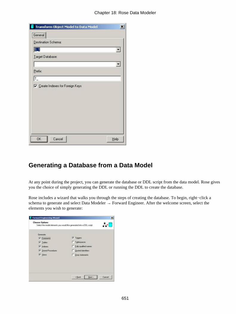
Generating a Database from a Data Model
At any point during the project, you can generate the database or DDL script from the data model. Rose givesyou the choice of simply generating the DDL or running the DDL to create the database.
Rose includes a wizard that walks you through the steps of creating the database. To begin, right−click aschema to generate and select Data Modeler → Forward Engineer. After the welcome screen, select theelements you wish to generate:
Chapter 18: Rose Data Modeler
651

Next, enter the name of the DDL file to create. If you want to create the DDL, but not run it, click Next. If youwant to run the new DDL against a database, select the Execute check box. Enter the connection informationfor your DBMS and press the Test Connection button to be sure that the connection is working properly.
Press Finish to complete the process. Rose will generate the DDL and optionally run it against the database. Ifany errors are encountered, Rose will add them to the log.
All of the tables, columns, and relationships in the schema will be generated in the DDL or database. Thefollowing example shows a table in the Rose model.
The following is the corresponding DDL:
CREATE TABLE T_Customer ( CUSTOMER_ID SMALLINT IDENTITY NOT NULL, FIRST_NAME VARCHAR ( 15 ) NOT NULL, LAST_NAME VARCHAR ( 15 ) NOT NULL, HOME_PHONE NUMERIC ( 10 ) NOT NULL, ADDRESS VARCHAR ( 20 ) NOT NULL, CITY VARCHAR ( 20 ) NOT NULL, STATE CHAR ( 2 ) NOT NULL, ZIP_CODE NUMERIC ( 5 ) NOT NULL, CONSTRAINT PK_T_Customer0 PRIMARY KEY NONCLUSTERED (CUSTOMER_ID), CONSTRAINT TC_T_Customer1 CHECK (CUSTOMER_ID > 1000)
Chapter 18: Rose Data Modeler
652

) ON TSP0GO
CREATE INDEX TC_T_Customer2 ON T_Customer (ZIP_CODE)GO
Updating an Existing Database
Once a database has been created, you may make changes to either the data model in Rose or the databaseitself. Frequently, the two get out of synchronization, which can cause difficulties when trying to furthermodify the database design or maintain the application later.
Rose includes a compare−and−synchronize feature to address this problem. The feature includes a graphical,side−by−side representation of the database and data model. Using this feature, you can select the changes tobe made to the data model or database to synchronize the two again.
To begin the synchronization, right−click a schema and select Data Modeler → Compare and Sync. You willbe given the option to synchronize with either a DDL script or a database. If you select DDL script, you willbe prompted for the name of the script. If you select database, you will be prompted for the databaseconnection information.
Next, select the options you would like to synchronize. Rose will always synchronize tables and constraints,but you can also synchronize indexes, triggers, and other elements.
Chapter 18: Rose Data Modeler
653

Rose will then display the differences between the model and the database, as shown in Figure 18.2. Select adifference in the table, and then select one of the following four options from the toolbar:
• Import, which will import the change from the database into the data model
• Export, which will export the change from the data model to the database
• Delete, which will remove the change from both the data model and the database
• Ignore, which will ignore the change
Figure 18.2: Model and database compare−and−synchronize feature
Once you finish the changes, select Next. Rose will allow you to preview the changes to be made. When youare satisfied with the list of changes, press Next to commit the changes.
Chapter 18: Rose Data Modeler
654

Reverse Engineering a Database
You can reverse engineer a database into a data model in Rose. When you reverse engineer the database, Rosewill create the database component in the Component view and the tables and other database elements in aschema in the Logical view. Once you have reverse engineered the database, you can generate an objectmodel or perform a synchronization using the methods described earlier in this chapter.
To begin the process, select Tools → Data Modeler → Reverse Engineer. After the welcome screen, you willbe asked whether to reverse engineer from a DDL script or a database. If you select DDL, you will beprompted for the target DBMS and the name of the file. If you select database, you will be prompted for thedatabase connection information.
Next, select the item(s) to reverse engineer. Tables and constraints will always be imported, but you can selectother elements to reverse engineer.
When you have finished, click Next. Rose will create a schema in the Logical view. Within this schema willbe the tables, constraints, and other model elements from your database. If Rose encounters any problemsduring the reverse−engineering process, these will be noted in the log. Rose will also create a new componentin the Component view. This component represents the database itself.
Chapter 18: Rose Data Modeler
655

Summary
In this chapter, we examined the data−modeling capabilities of Rose. Combining the object model and datamodel into a single tool helps the team gain a more complete understanding of the system structure andorganization. The forward− and reverse−engineering capabilities help you ensure that your object model, datamodel, and database stay synchronized.
In this chapter, we specifically discussed the following:
• The differences between an object model and a data model
• How to create a data model
• How to add data−modeling elements
• How to generate an object model from a data model
• How to generate a data model from an object model
• How to generate and reverse engineer a database
• How to keep your object model, data model, and database synchronized
In the next chapter, we'll focus on web development, looking at the different stereotypes and tools Roseprovides to model an Internet or intranet application. With these tools, you can model ASP, JSP, HTMLpages, and other web objects. Using Class diagrams, you can see the relationships between these objects andanalyze your application architecture. The Rose Web Modeler add−in is an excellent way to visualize existingapplications or to design new ones.
Chapter 18: Rose Data Modeler
656

Chapter 19: Web ModelingIn this world of e−business, e−commerce, and e−government, no discussion of UML would be completewithout a discussion of web modeling. Although similar to traditional client/server applications, webapplications have their own unique benefits and challenges, which naturally affect their design.
Rose 2001, 2001A, and 2002 include an add−in that supports the code generation and reverse engineering ofweb applications. You can model and generate HTML pages, ASP pages, JSP pages, and other types of webclasses using Rose.
Modeling a Web Application
Whether you are creating a new web application from scratch, or reverse engineering and modifying anexisting application (see "Reverse Engineering a Web Application" later in this chapter), it is necessary to firstgain an understanding of the different web stereotypes and relationships. Before we look at these, however,let's take a look at web architecture in general.
In many ways, a web application is similar to a traditional distributed application. The logic is divided intotwo or more areas, or tiers. At a minimum, the presentation logic is separated into the presentation layer, andthe business logic is separated into a server logic layer. The presentation layer runs on the client, while thebusiness logic runs on the server. In many cases, the business logic is separated into two or more layers of itsown. For example, the logic dealing with the connection to the database may be separated from the rest of thebusiness logic.
One of the primary differences between a web application and a traditional distributed system is in thepersistency of the connection between the two (or more) layers. In a distributed system, once objects havebeen instantiated on the client and the server, they can communicate with each other only when needed. Aweb application, on the other hand, is stateless—once the communication between the client and the serverends, the server loses all information about the client. It no longer knows who was logged in or what theywere doing. One way to manage this challenge is through the use of cookies. A cookie is a file that resides onthe client and can store state information about the client so that the next time a connection is established withthe server, the contents of the cookie can be used to give the server state information.
Another difference lies in the deployment environment. An advantage of the Web, of course, is the ability toreach thousands of users without needing to worry about setting up each machine. The disadvantage is theability to reach thousands of machines, many of which may have slightly different configurations. Differentbrowsers, operating systems, connection speed, processor, memory configuration, and other factors cancomplicate web deployment. Not all components will run with all browsers, so the designer has extra work todo if the application must run on several different types of browsers.
There are two primary patterns to a web architecture: thin client and thick client. In a thin client architecture,very little logic is placed on the client side. Few, if any, ActiveX controls, applets, or other components aredownloaded to the client browser and run on the client machine. Two of the advantages of this approach arespeed and portability. Downloading components to the client can be very slow, so minimizing the number ofdownloads helps to increase the speed of the application. A thin client architecture can also be more portable,because not every component will work on every type of browser. Minimizing the number of differentcomponent technologies needed for your application can help ensure that the application will work in differentbrowsers. The disadvantage to the thin client approach is that the user interface can't necessarily have a lot ofbells and whistles; client−side components may be needed to provide an enhanced user interface.
657

The second approach to a web application is to use a thick client architecture. In a thick client, more logic isrun on the client. When a component is needed on the client, it will be automatically downloaded from theserver. This approach gives the team the option of including more sophisticated controls on the user interface.The team can also build applets or other components to run some logic on the client. The advantage of thisapproach is the ability to create more robust user interfaces. The disadvantages are speed and portability. Thedownloads take time, and there is no guarantee that the different browsers will support the application if toomany different types of components are downloaded.
The process of modeling a web application begins just like the process of modeling a client/serverapplication—with analysis. The team defines the use cases, gathers and documents the requirements, andwrites the flow of events for the use cases. We won't discuss this in detail here; see Chapter 4, "Use Cases andActors," for information about use cases and actors.
Once the flow of events has been written for a use case and its requirements have been documented, thedesign process can begin for that use case. This involves the creation of Sequence diagrams, Collaborationdiagrams, Class diagrams, Statechart diagrams, Component diagrams, and Deployment diagrams.
As in a client/server application, Sequence and Collaboration diagrams show the objects that participate in ause case scenario. As the designers are building and reviewing the Sequence diagrams, however, they mustkeep the web architecture in mind. There are a few primary considerations. First, because the application isstateless, the designers cannot assume that once an object is instantiated, it can be accessed indefinitely by theother objects. As soon as the connection between the client and server is broken, objects on one layer cannotaccess objects on the other, and the server loses all information about the state of the client. The designers can,however, use cookies and session objects to store state information. A cookie is a small file on the clientmachine that can be used to store state information, while a session object is created on the server and holdsinformation about a particular client through the life of the client's session. After a period of time, say 30minutes, the server assumes that the client has timed out, and the session object will be released.
If the team uses session objects, they will appear in the Sequence and Collaboration diagrams, just as anyother objects. One very useful tool in Rose 2001A and 2002 is the ability to place destruction marks on theSequence diagrams. This notation can make it easier for the team to remember which objects are available inmemory at which point in time.
A second consideration in web modeling is that client pages should not have access to server resources. Thedesigners should ensure that none of the pages, applets, or other client−side components can directly accessthe server. Instead, they should access a server page, which can then access the server−side components. If theapplication is a thin client, the designers should minimize the number of components downloaded to the clientmachine. As they are building the Sequence and Collaboration diagrams, therefore, the team should not usemany client−side components.
Before you begin modeling, you will need an area in Rose to create your classes. You will work in the Logicalview, but you must first set up a virtual directory. A virtual directory is a stereotyped package in Rose thatrepresents a physical directory on your network. Any classes in the virtual directory will be generated into thephysical directory.
Chapter 19: Web Modeling
658

To create the virtual directory:
1. Right−click the Logical view in the browser.
2. Select Web Modeler → New → Virtual Directory.
3. Right−click the new virtual directory. The specification window will appear:
4. Select the platform (ASP or JSP) you will use for this application.
5. Enter the URL of your web application. Rose requires the URL to generate code or to reverseengineer web classes into the model.
6. Enter the virtual directory name. This is the name of the virtual directory package that will appear inthe Logical view in Rose. All of the classes for this web application will be placed in this package.
7. Enter the physical location. All classes in this web application will be generated into this location andreverse engineered from this location.
Once you have created the virtual directory, you can create web objects inside it.
Web Class Stereotypes
To model your web application, you will need to create classes to represent your client pages, server pages,and HTML pages. To complete the picture, you can then add relationships between these model elements.When Rose generates code, it will examine both the classes and the relationships.
There are three different types of class stereotypes that can be generated or reverse engineered in Rose: clientpages, server pages, and HTML pages.
Chapter 19: Web Modeling
659

Client Pages
Client pages are HTML−formatted pages that run on the client. These contain some functionality, buttypically do not include intensive business logic. Logic on the client pages is usually related to presentation ofthe data. Client pages do not directly access business objects on the server; this is the role of a server page. InRose, a client page has the following notation:
The functionality in a client page can be programmed in either VBScript or JavaScript. Any scripting here isstrictly client−side. For example, the client page may format some text on the screen.
Client pages do have access to any resources available on the client. These resources could include:
• ActiveX controls, which are components based on the Microsoft COM model, that are downloaded tothe client machine.
• JavaScript objects, which could be objects provided by the document object model, such as window,frame, document, image, etc. These could also be custom objects defined by the programmer. Thesecustom objects can be assigned their own attributes and operations, but are not reverse engineered intoRose.
• Java applets, which are components that, like ActiveX controls, are downloaded to the client machineand run on the client.
Typically, you use these three types of components to add complex functionality to the client. HTML willgive you some flexibility, but it is frequently not sophisticated enough to program complex client−sidebehavior.
ActiveX controls and applets can be modeled in Rose as classes or components with the stereotype of<<ActiveX>> or <<Applet>>. Because a component may consist of several classes, you can simply model anActiveX control or applet in the Component view. If you want to model the classes within a component orshow the relationships between your classes and the component, you can model the control or applet as a classin the Logical view as well.
To add a client page:
1. Right−click the virtual directory in the Logical view.
2. Select Web Modeler → New → Client Page.
3. Enter the name of the new page.
Chapter 19: Web Modeling
660

OR
Create a server page using the method described in the following section, "Server Pages." A client page willautomatically be created for each server page you create using this method.
In the specification for the client page, you can set detailed attributes for the client page. Table 19.1 lists theattributes and their meanings:
Table 19.1: Client Page Attributes
Attribute Specification WindowTab
Meaning
Alink General Link color
Background General URI to background image
BgColor General Background color
BottomMargin General Bottom margin in pixels
Class General Class name for element
Dir General Text direction for element
ID General Element name
Lang General Language of element's content
LeftMargin General Left margin in pixels
Link General Text color of links
MarginHeight General Frame margin height in pixels
MarginWidth General Frame margin width in pixels
RightMargin General Right margin in pixels
Style General Style information for element
Text General Text color
Title General Additional element information
TopMargin General Top margin in pixels
Vlink General Link color for visited links
OnLoad Events Process to run on loading the page
OnUnload Events Process to run when unloading the page
FileName RTE Options Name of physical file for page (ASP, JSP, HTML)
RTESynchronizationRTE Options Whether or not to generate code for this pageServer Pages
Server pages are objects that have access to the resources available on the server. For example, if somesecurity processing needs to take place, a server page would communicate with various components on theserver to perform that processing. Separating the application into client pages and server pages helps toseparate the presentation logic from the business logic, which aids in both maintenance and reuse. In Rose, aserver page has the following notation:
Chapter 19: Web Modeling
661

Unlike a client page, a server page has full access to the server's resources. It can communicate with theobjects on the server to carry out business functionality, and then build client pages to show the results of theprocessing to the end user. One server page can also redirect control to another, allowing the second serverpage to take over processing.
To create a server page:
1. Right−click the virtual directory in the Logical view.
2. Select Web Modeler → New → Server Page.
3. Enter the name of the new page.
Rose will create the server page, and will also automatically create a client page for you. The client pagehandles the client−side functionality, such as display logic. The server page handles the business processingand builds the client page. Rose will also automatically add a build relationship between the server page andthe client page. We will discuss relationships shortly.
In the specification window for the server page, you can set the following two values:
• File Name is the physical name of the page (ASP, JSP, or HTML).
• RTE Synchronization controls whether the page will be generated or not.
Forms
Forms are simple HTML pages that contain text boxes, list boxes, and other data input controls. The purposeof a form is simply to receive information from the end user and to display information to the end user.Business logic is not included on a form.
A client page may contain one or more forms. Each form on a client page is associated with that page using anaggregation relationship. Fields on the form are modeled as attributes of the form, and are given the stereotypeHTML Input. In Rose, the following symbol is used to represent a form:
To create an HTML form:
1.
Chapter 19: Web Modeling
662

Right−click the client page on which the form is to be located.
2. Select Web Modeler → New → HTML Form.
3. Enter the name of the new form.
Like client pages and server pages, forms have detailed specifications that will be used during thecode−generation process. Any values that you set on the General tab will appear in the generated HTML.Table 19.2 lists the specifications for the HTML Form stereotype, and the purpose of each specification.
Table 19.2: HTML Form Attributes
Attribute Specification WindowTab
Meaning
Action General Form−processing agent
Class General Class name for element
Enctype General Content type used to encode the form's data
ID General Element name
Lang General Language of element's content
Method General HTTP method to submit form's data
Style General Cascading style sheet for element
Target General Name of frame target
Onblur Events Process to run when element loses focus
Onclick Events Process to run on mouse click
Ondblclick Events Process to run on mouse double−click
Onfocus Events Process to run when element gains focus
Onkeydown Events Process to run when a key is pressed down
Onkeypress Events Process to run when an alphanumeric key is pressed
Onkeyup Events Process to run when a key is released
Onmousedown Events Process to run when the mouse button is pressed
Onmousemove Events Process to run when the mouse moves
Onmouseout Events Process to run when the mouse cursor is moved off of theelement
Onmouseover Events Process to run when the mouse cursor is placed on the element
Onmouseup Events Process to run when the mouse button is released
Onreset Events Process to run when the form is reset
Onsubmit Events Process to run when the form is submitted
RTE SynchronizationRTE Options Whether or not to generate the element
Resolve RelativePaths Dynamically
RTE Options Automatically resolve paths in referenced files(Note: Settingthis field to Default will set it to True/False, depending uponwhat is set in Tools → Web Modeler → User Preferences.)
An HTML form is really just a collection of input fields. Rose supports three types of input fields: an HTML
Chapter 19: Web Modeling
663

Input, an HTML Select, or an HTML TextArea. Once you have added a form, you can add more input fieldsusing Web Modeler.
An HTML Input is a field on the form. It can have one of these types: text, password, check box, radio,submit, reset, file, hidden, image, or button. The HTML input will be modeled as an attribute of the form.
To add a new HTML Input field:
1. Right−click the HTML form.
2. Select Web Modeler → New → HTML Input.
3. Select the type of input (text, checkbox, etc.).
4. Enter the name, ID, and value of the input.
5. Select OK to create the new input.
6. Right−click the new input.
7. Edit the input specifications, event handlers, and round−trip engineering options on the specificationwindow.
This HTML input will be generated in the code as follows:
<input ID="PWD" Name="PasswordBox" Type="password">
An HTML Select is a select box field. The select box has a list of values, and allows the user to select one ormore of the values in the list.
Chapter 19: Web Modeling
664

To add a new HTML Select field:
1. Right−click the HTML form.
2. Select Web Modeler → New → HTML Select.
3. Enter the name and ID of the field.
4. Select OK to create the new field.
5. Right−click the new field.
6. Edit the field specifications, event handlers, and round−trip engineering options on the specificationwindow.
The field will be generated in the code as follows:
<select ID="1" Name="HTMLSelect"> </select>
An HTML TextArea is a multi−line text field on an HTML form. These fields can be used any time the userneeds to enter long strings of text. Using the attributes associated with the field, you can set the number oflines that will display on the text area, whether the text area is editable, the tab index for the control, and otherproperties.
To add a new HTML TextArea field:
1. Right−click the HTML form.
2. Select Web Modeler → New → HTML TextArea.
3.
Chapter 19: Web Modeling
665

Enter the name and ID of the field.
4. Select OK to create the new field.
5. Right−click the new field.
6. Edit the field specifications, event handlers, and round−trip engineering options on the specificationwindow.
The field will be generated in the code as follows:
<textarea ID="TXT1" Name="TextArea1" Rows="4">
All of these types of fields (Input, Select, or TextArea) will appear as attributes of the form on which they aredisplayed. When code is generated, Rose will examine both the fields and their properties to determine whatHTML to generate.
Relationships
Now that we have classes in the model, the next step is to add relationships. There are four primary types ofrelationships between web elements: link relationships, build relationships, redirect relationships, and submitrelationships.
Chapter 19: Web Modeling
666

A link relationship is used to represent a hypertext link between two client pages or between a client page anda server page. The link is drawn as an association relationship between two classes, with a stereotype of<<Link>>.
To set the detailed specifications for the link, right−click the association and select Open Specification. Table19.3 lists the properties of a link association.
Table 19.3: Link Relationship Attributes
Attribute Specification WindowTab
Meaning
AccessKey General Key that will set focus to the element
Class General Class name for element
Dir General Directional orientation
HREF General Link location
ID General Element name
Lang General Language of element's content
Name General Link destination
Style General Cascading style sheet for element
TabIndex General Tab order of the element
Target General Where the link displays in the browser
Title General Document referenced by HREF attribute
Onblur Events Process to run when element loses focus
Onclick Events Process to run on mouse click
Ondblclick Events Process to run on mouse double−click
Onfocus Events Process to run when element gains focus
Onkeydown Events Process to run when a key is pressed down
Onkeypress Events Process to run when an alphanumeric key is pressed
Onkeyup Events Process to run when a key is released
Onmousedown Events Process to run when the mouse button is pressed
Onmousemove Events Process to run when the mouse moves
Onmouseout Events Process to run when the mouse cursor is moved off of theelement
Onmouseover Events Process to run when the mouse cursor is placed on the element
Onmouseup Events Process to run when the mouse button is released
RTE SynchronizationRTE Options Whether or not to generate the element
Resolve RelativePaths Dynamically
RTE Options Automatically resolve paths in referenced files(Note: Settingthis field to Default will set it to True/False, depending uponwhat is set in Tools → Web Modeler → User Preferences.)
Chapter 19: Web Modeling
667
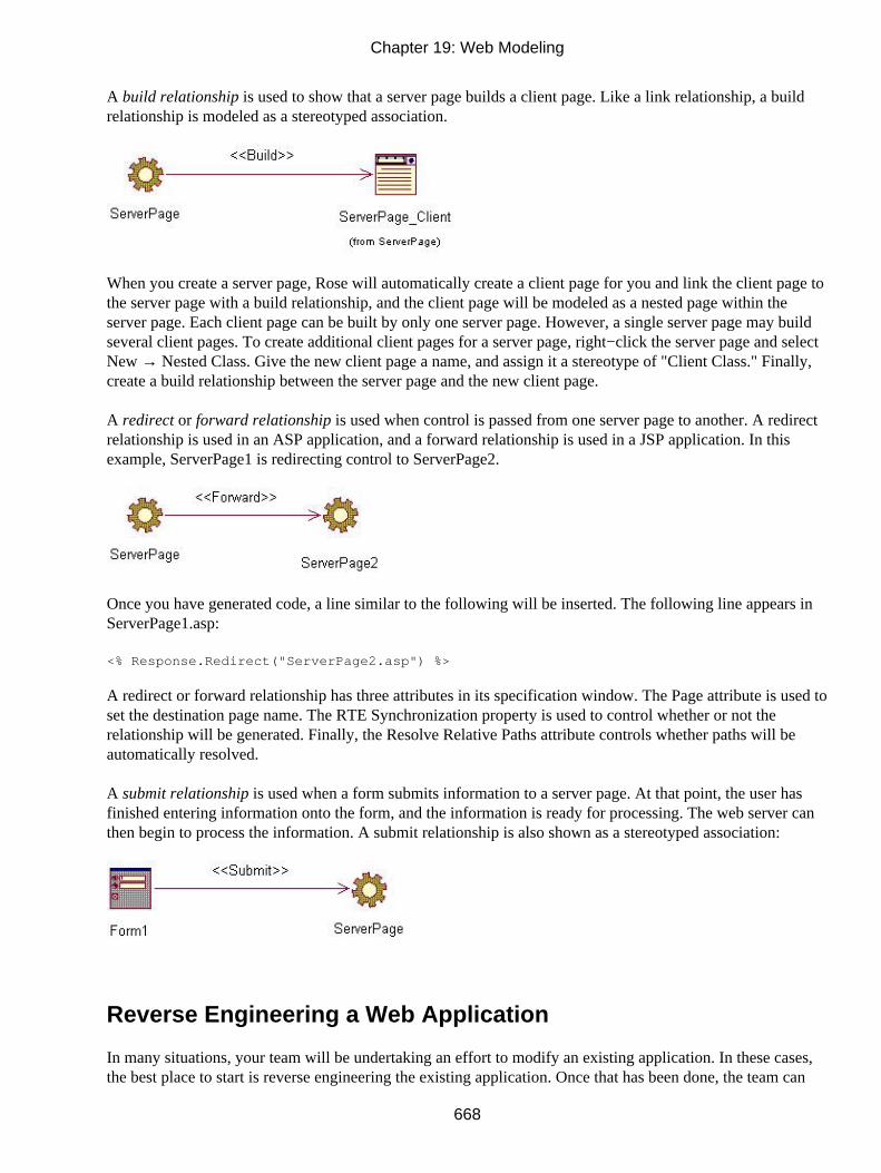
A build relationship is used to show that a server page builds a client page. Like a link relationship, a buildrelationship is modeled as a stereotyped association.
When you create a server page, Rose will automatically create a client page for you and link the client page tothe server page with a build relationship, and the client page will be modeled as a nested page within theserver page. Each client page can be built by only one server page. However, a single server page may buildseveral client pages. To create additional client pages for a server page, right−click the server page and selectNew → Nested Class. Give the new client page a name, and assign it a stereotype of "Client Class." Finally,create a build relationship between the server page and the new client page.
A redirect or forward relationship is used when control is passed from one server page to another. A redirectrelationship is used in an ASP application, and a forward relationship is used in a JSP application. In thisexample, ServerPage1 is redirecting control to ServerPage2.
Once you have generated code, a line similar to the following will be inserted. The following line appears inServerPage1.asp:
<% Response.Redirect("ServerPage2.asp") %>
A redirect or forward relationship has three attributes in its specification window. The Page attribute is used toset the destination page name. The RTE Synchronization property is used to control whether or not therelationship will be generated. Finally, the Resolve Relative Paths attribute controls whether paths will beautomatically resolved.
A submit relationship is used when a form submits information to a server page. At that point, the user hasfinished entering information onto the form, and the information is ready for processing. The web server canthen begin to process the information. A submit relationship is also shown as a stereotyped association:
Reverse Engineering a Web Application
In many situations, your team will be undertaking an effort to modify an existing application. In these cases,the best place to start is reverse engineering the existing application. Once that has been done, the team can
Chapter 19: Web Modeling
668

examine the current system architecture, make any needed additions or modifications to the design, andgenerate the code.
Rose supports the reverse engineering of ASP, JSP, and HTML pages. It assigns the appropriate stereotypes tothe classes and creates relationships between them.
Begin the reverse−engineering process by selecting Tools → Web Modeler → Reverse Engineer a New WebApplication. After the welcome screen, you will be prompted for the location of your application.
First, select the platform—either ASP or JSP—that is used by your application. In the URL Name field, enterthe URL of the application. In the Virtual Directory Name field, enter the name of a package to create inRose. During the reverse−engineering process, Rose will create a package in the Logical view with this name.All reverse−engineered classes and relationships will be placed inside this package. Finally, in the PhysicalLocation field, enter the path to the application files.
Next, you will see a treeview with all available ASP, JSP, and HTML pages to reverse engineer. By default,all pages will be selected. Select the page(s) you wish to reverse engineer and press Next.
Rose will examine each of the files and reverse engineer them into the model. If any errors occur, Rose willenter them into the log.
An ASP page is reverse engineered as a class with the stereotype <<Server Page>> and an associated classwith the stereotype <<Client Page>>. The server page and the client page are linked with a build relationship.The VBScript or Java on the ASP or JSP server page is modeled as an operation on that page.
Chapter 19: Web Modeling
669

The form(s) on the client page are modeled as separate classes in Rose, with a stereotype of <<Form>>. Anycontrols on the form are reverse engineered as attributes of the form.
Generating Code for a Web Application
After you have reverse engineered and modified a web application or modeled a web application from scratch,Rose will generate code for you. Rose will create the HTML, ASP, and JSP files from the model.
Rose will generate code for the following:
• Server pages
• Client pages
• Forms
• Form input fields
• Form select fields
• Form text area fields
• Redirect or forward relationships
• Link relationships
When you generate code, Rose will first look for an existing file with the same name as the class you aregenerating. If a file is found, Rose will update it. Otherwise, a new file is created. The stereotype of the class,coupled with the platform of the virtual directory, controls what type of file will be created. The files createdfor server pages will be either ASP or JSP files. A client page with no relationship to a server page willgenerate an HTML file.
To generate code from your model:
1.
Chapter 19: Web Modeling
670

Right−click the virtual directory.
2. Select Web Modeler → Generate Code.
3. Rose will generate code, and then log any errors to the log window.
Summary
In this chapter, we examined the modeling of web applications with UML and Rose. To a certain extent,modeling web applications is similar to modeling other applications. We still create use cases and the flow ofevents. We still create Sequence and Collaboration diagrams that show how the objects interact with eachother. And we still create Class diagrams to show what classes are needed and how they relate.
A chief difference is in the kinds of classes and relationships that are used in web modeling. By stereotypingour classes as client pages, server pages, or forms, we can be sure that Rose will generate the appropriatesource code. Where client/server applications have standard association relationships, web applications have afew types of associations: build relationships, link relationships, submit relationships, and redirectrelationships.
Once you have modeled your web application, Rose can generate code for you. You can use the round−tripengineering capabilities of Rose to update your code, update the model, and keep the model and codeconsistent.
Like the rest of UML, the web notation will continue to evolve as new web languages and technologies areintroduced. Rose will evolve along with the notation, providing support for these new concepts and helpingorganizations design both client/server and web applications more effectively.
Chapter 19: Web Modeling
671
Appendix: Getting Started with UMLUML is made up of a number of different types of diagrams. Each gives the reader a slightly differentperspective of the system's design. Some are high−level and intended to give you an understanding of thefunctionality in the system. Others are very detailed and include the specific classes and components that willbe built to implement the system. Still others are midway between these two levels: They provide designdetails but from a higher−level perspective.
The set of diagrams gives you a complete picture of the system design. Different members of the team createdifferent types of diagrams, and each is used by a different set of people. While building the system, thedevelopers will refer to the diagrams to understand what classes and components need to be built. Later, whena team is maintaining the system, they can refer to the diagrams to understand the system structure, analyzethe impact of a potential change, and document any design changes that were made.
UML is constantly being refined to incorporate new ideas and technologies. For example, it can now be usedto model an XML DTD. As the object−oriented world changes, UML can change along with it. At the sametime, though, it is a standard, and modifications to it are centrally managed. UML is controlled by the ObjectManagement Group, which has members from large and small companies around the world.
Rational Software has developed a systems development lifecycle titled the Rational Unified Process (RUP).RUP complements UML by providing specific process steps, roles, responsibilities, guidelines, workflows,and templates that can be used to develop software. Although RUP complements UML, you may use UMLwithout using RUP.
UML includes many different diagram types. Business Use Case diagrams are used to model the organization.Business workflow (activity) diagrams are used to show the processes within the organization. Use Casediagrams show the functionality to be provided by the system and the people and entities that interact with thesystem. Activity diagrams show the flow of logic through a use case. Sequence and Collaboration diagramsshow the objects that are needed to implement the functionality of a use case, and include the messagesbetween the objects. Statechart diagrams are used to model dynamic behavior, and are frequently used inreal−time systems. Component diagrams show the components that will be created for the system and therelationships between them. Finally, Deployment diagrams are used to show the network structure and wherethe system will be deployed on the network.
Building a Business Use Case Diagram
A Business Use Case diagram is a mechanism for modeling the work done by the organization itself. Thediagram contains business use cases, which are functions performed by the organization; business actors,which are entities outside the organization that interact with it; and business workers, which are roles withinthe organization.
The Business Use Case diagram gives someone an understanding of what the organization does and whointeracts with it. It is supplemented by activity diagrams, which detail the workflows within the organization.
A business process team or a business analysis team typically creates the diagram. It is nontechnical, and canbe used by any member of the organization to gain a better understanding of the organization.
To create a new Business Use Case diagram, follow these steps:
1. 672

Right−click a package in the Use Case view.
2. Select New → Use Case Diagram.
3. Right−click the toolbar and select Customize.
4. Add buttons for business actor, business use case, business worker, business entity, and organizationalunit.
A Business Use Case diagram shows a subset of the business use cases, business workers, and business actorsof the organization.
Follow these steps to add business actors to your diagram:
1. Determine the business actors.
2. Select the Business Actor toolbar button.
3. Click in the Use Case diagram to add the actor.
4. Name the actor.
A business actor is an individual, group, company, or other entity outside of the organization that directlyinteracts with the organization.
Appendix: Getting Started with UML
673

Use these steps to add business workers to the diagram:
1. Determine the business workers.
2. Select the Business Worker toolbar button.
3. Click in the Use Case diagram to add the worker.
4. Name the worker.
A business worker is a role within the organization.
Follow these steps to add relationships between the business actors and business use cases:
1. Select the Unidirectional Association toolbar button.
2. Drag an arrow from the actor or business worker to the use case.
A communicates relationship between a business actor and a business use case shows how a business actor orbusiness worker interacts with the organization.
Follow these steps to group the business actors, business workers, and business use cases into organizationunits.
1. Select the Organization Unit toolbar button.
2. Click inside a Business Use Case diagram to place the organization unit.
3. In the browser, drag and drop business actors, business workers, business use cases, Business Use
Appendix: Getting Started with UML
674
Case diagrams, and activity diagrams into the new organization unit.
An organization unit is used to group together business modeling elements such as business actors andbusiness use cases. These units can help to organize the model and show how the company itself is organized.
Building a Workflow (Activity) Diagram
Activity diagrams are commonly used in two situations. In business modeling, they can be used to documentthe workflow of a process within the organization. In systems modeling, they can be used to document theflow of logic through a use case.
An activity diagram that focuses on workflow shows you the people or groups within the workflow, the stepsin the process, decision points in the process, areas where steps in the process can occur in parallel, objectsaffected by the workflow, states of the objects, and transitions between steps in the process. UML containsnotation for all of these items.
To create a new activity diagram:
1. Right−click a use case or package in the Use Case view.
2. Select New → Activity Diagram.
An activity diagram models a process in the organization. It can be used to analyze either existing or newprocesses. These types of diagrams are frequently used in business process re−engineering efforts or in anysituation where the workflow is complex or undocumented.
Appendix: Getting Started with UML
675

To partition your diagram into sections for each actor or worker's responsibilities, follow these steps:
1. Determine the participants in the workflow.
2. Select the Swimlane toolbar button.
3. Click in the diagram to add the swimlane.
4. Name the swimlane with the name of the role or group in the workflow.
A swimlane is a vertical section of the diagram that will contain all of the workflow steps that a particularperson or group performs. You divide the diagram into many swimlanes, one for each person or group in theprocess.
Appendix: Getting Started with UML
676

To add detailed steps to the diagram:
1. Select the Activity toolbar button.
2. Click in the diagram to add the activity.
3. Name the activity.
An activity is a step in the workflow. It can contain actions, which are steps within the activity. The activity isplaced in the swimlane of the individual or group that performs the activity.
Follow these steps to set the sequence of the activities:
1. Select the Transition toolbar button.
2. Drag an arrow from one activity to the next.
3.
Appendix: Getting Started with UML
677

Right−click the transition arrow and select Open Specification.
4. Optionally add an event and event arguments on the General tab.
5. Optionally add a guard condition, action, send event, send event arguments, and send target on theDetail tab.
A transition shows how the process moves from one step (activity) to the next. An event triggers themovement from one activity to another. An event can have arguments. A guard condition controls when thetransition can or cannot occur; the guard condition must be true for the transition to occur. An action occurswhile the process is transitioning from one activity to another. It is typically a quick process that occurs as partof the transition itself. The send target suggests that, as part of the transition, a message is sent to some object.The send target is the object receiving the message. The send event is a message sent to another object. It mayhave arguments.
Follow these steps to add decision points to the logic:
1. Select the Decision toolbar button.
2. Click in the diagram to place the decision.
3. Draw transitions from the decision to the activities that may occur after the decision.
4. Place guard conditions on each transition arrow. The guard conditions will control which path is takenafter the decision.
A decision point in the workflow indicates when the workflow can take two or more different paths.Transition arrows leading from the decision to activities show the different paths that the workflow canfollow. Guard conditions on the transitions indicate under which conditions each path will be followed. Guardconditions must be mutually exclusive.
To add objects to the workflow:
1. Select the Object toolbar button.
2. Click inside the diagram to place the object.
3.
Appendix: Getting Started with UML
678

Select the Object Flow toolbar button.
4. Drag an arrow from an activity to the object it affects or from the object to the activity that uses theobject as input.
An object is an entity affected by the workflow. It can serve as input into a process step, in which case adashed object flow arrow is drawn from the object to the process step. Or, it can be affected by a process step,in which case an object flow arrow is drawn from the step to the object.
Follow these steps to add synchronizations to the workflow:
1. Select the Synchronization toolbar button.
2. Click in the diagram to place the synchronization bar.
3. Draw a transition arrow from an activity to the synchronization bar, indicating that the parallelprocessing begins after that activity.
4. Draw transition arrows from the synchronization bar to the activities that can occur in parallel.
5. Create another synchronization bar to indicate the end of the parallel processing.
6. Draw transition arrows from the synchronous activities to the final synchronization bar to indicate thatthe parallel processing stops once all of those activities are complete.
A synchronization indicates that two or more steps in the workflow may be completed in parallel. Asynchronization bar is used to show where two or more activities may occur simultaneously. These can bevery effective in analyzing the efficiency of a workflow; examining the amount of parallel activity can help tooptimize a workflow.
Building a Use Case Diagram
A Use Case diagram is a graphical representation of the high−level system scope. It includes use cases, whichare pieces of functionality the system will provide, and actors, who are the users of the system. Looking at aUse Case diagram, you should easily be able to tell what the system will do and who will interact with it.
Appendix: Getting Started with UML
679

You can create one or more Use Case diagrams for a single system. If you create more than one, each willshow a subset of the actors and/or use cases in the system. You can also group the use cases and actors intopackages to help organize the model.
The Use Case diagram can be helpful in communicating with the end users of the system. It is designed to bestraightforward and nontechnical so that everyone on the team can come to a common understanding of thesystem scope. It is usually created by the technical team, but in conjunction with an end user representative.
To create a new Use Case diagram:
1. Right−click a package in the Use Case view.
2. Select New → Use Case Diagram.
A Use Case diagram shows a subset of the use cases and actors in the system. You can create as many UseCase diagrams as you need to fully document the system scope.
Follow these steps to add actors to the diagram:
1. Determine the actors for your system.
2.
Appendix: Getting Started with UML
680

Select the Actor toolbar button.
3. Click in the Use Case diagram to add the actor.
4. Name the actor.
An actor is a person, system, piece of hardware, or other thing that interacts with your system.
Follow these steps to add use cases to the diagram:
1. Add the use cases to the diagram.
2. Select the Use Case toolbar button.
3. Click in the Use Case diagram to add the use case.
4. Give the use case a name.
A use case is a piece of functionality the system will provide. It is usually named in the format<verb><noun>, such as "Deposit Check" or "Withdraw Cash." Use cases are high−level andimplementation−independent.
To add relationships between the actors and use cases:
1. Select the Unidirectional Association toolbar button.
2. Drag an arrow from the actor to the use case.
A communicates relationship between an actor and a use case indicates that the actor initiates the use case. Anactor may initiate one or more use cases.
Appendix: Getting Started with UML
681

To add includes relationships between appropriate use cases:
1. Select the Include Use Case toolbar button.
2. Drag an arrow from a use case to the use case it includes.
An includes relationship suggests that one use case must include another. In other words, running one usecase means that the other must be run as well. One use case may be included by one or more other use cases.
To add extends relationships between appropriate use cases:
1. Select the Extend Use Case toolbar button.
2. Drag an arrow from the extending use case to the use case it extends.
An extends relationship is used when one use case optionally extends the functionality provided by another.In other words, if one use case runs, an extending use case may or may not run.
Follow these steps to group the use cases, actors, and other elements into packages:
1. Right−click the Use Case view or another package and select New → Package.
2. Name the new package.
3. In the browser, drag and drop use cases, actors, Use Case diagrams, or other modeling elements intothe new package.
A package is a UML mechanism used to group items together. Grouping can help to organize the model, andcan also help in managing any changes in the model elements. You may nest one package inside another tofurther organize the model.
Appendix: Getting Started with UML
682

To add generalization relationships between appropriate use cases:
1. Select the Generalization toolbar button.
2. Drag an arrow from the child use case to the parent use case.
A generalization relationship between two use cases indicates that one use case (the child) inherits all of thefunctionality provided by the other use case (the parent).
To add generalization relationships between appropriate actors:
1. Select the Generalization toolbar button.
2. Drag an arrow from the child actor to the parent actor.
A generalization relationship between actors indicates that one actor (the child) inherits the characteristics ofanother actor (the parent). The child actor may initiate all of the use cases that the parent can initiate.
Appendix: Getting Started with UML
683

Building an Interaction Diagram
An Interaction diagram is a graphical representation of how the objects and actors in a system interact withone another to achieve the desired goal of the system. There are two types of Interaction diagrams, Sequencediagrams and Collaboration diagrams. Sequence diagrams illustrate the interactions of objects along atimeline. Collaboration diagrams show the interactions, but without the timeline. These two diagrams displaythe same information, just in different ways.
You can create multiple Interaction diagrams for each use case in a system. More than one is typically createdto illustrate the interaction given different scenarios.
Sequence diagrams are usually created to show the flow of functionality and control throughout the objects inthe system. Collaboration diagrams are typically used to illustrate which objects communicate with otherobjects. Sequence diagrams answer questions about how the system will work. Collaboration diagrams answerquestions about the soundness of the structure of the system.
To create a new Sequence diagram:
1. Right−click a use case in the Use Case view.
2. Select New → Sequence Diagram.
Once you have created the Sequence diagram, you next need to determine which actors and objects to placeon it. One method is to drag all actors involved in the use case to the Sequence diagram, then walk through thefunctionality, adding objects to facilitate that functionality as needed.
To add actors and objects to the Sequence diagram:
1. Select any actors involved in the use case and drag them into the new Sequence diagram.
2. Select the Object toolbar button.
3.
Appendix: Getting Started with UML
684

Click in the Sequence diagram to add an object.
4. Name the object.
5. Add additional objects as needed.
At this point, the objects and actors are on the Sequence diagram, but Interaction diagrams would be fairlyuseless without showing the interactions. Messages are used to accomplish this. A message is simply someform of communication between one object or actor and another.
Messages can also be reflexive, meaning that the object communicates some information to itself.
Follow these steps to add messages to the diagram:
1. Select the Message toolbar button.
2. Click on the actor or object to initiate the message.
3. Drag the message to the actor or object to receive the message.
4.
Appendix: Getting Started with UML
685

Name the message.
Tip Pressing F5 on a Sequence diagram will create the corresponding Collaboration diagram. You can alsouse F5 to toggle between a Sequence diagram and its Collaboration diagram.
Collaboration diagrams are not time−based, but show the interactions of the objects as a whole. This is usefulfor pointing out potential bottlenecks (objects that individually communicate with a large number of objects).Sequencing of messages is shown on a Collaboration diagram by numbering the messages.
To create a new Collaboration diagram:
1. Right−click a use case in the Use Case view.
2. Select New → Collaboration Diagram.
Once you have created the Collaboration diagram, you then need to determine which actors and objects toplace on it. One method is to drag all actors involved in the use case to the Collaboration diagram, then walkthrough the functionality, adding objects as needed to facilitate that functionality.
To add actors and objects to a Collaboration diagram:
1. Select any actors involved in the use case and drag them into the new Collaboration diagram.
2. Select the Object toolbar button.
3. Click in the Collaboration diagram to add an object.
4. Name the object.
5. Add additional objects as needed.
Appendix: Getting Started with UML
686
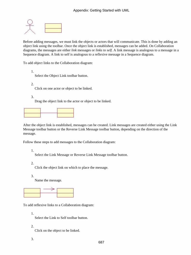
Before adding messages, we must link the objects or actors that will communicate. This is done by adding anobject link using the toolbar. Once the object link is established, messages can be added. On Collaborationdiagrams, the messages are either link messages or links to self. A link message is analogous to a message in aSequence diagram. A link to self is analogous to a reflexive message in a Sequence diagram.
To add object links to the Collaboration diagram:
1. Select the Object Link toolbar button.
2. Click on one actor or object to be linked.
3. Drag the object link to the actor or object to be linked.
After the object link is established, messages can be created. Link messages are created either using the LinkMessage toolbar button or the Reverse Link Message toolbar button, depending on the direction of themessage.
Follow these steps to add messages to the Collaboration diagram:
1. Select the Link Message or Reverse Link Message toolbar button.
2. Click the object link on which to place the message.
3. Name the message.
To add reflexive links to a Collaboration diagram:
1. Select the Link to Self toolbar button.
2. Click on the object to be linked.
3.
Appendix: Getting Started with UML
687

Name the reflexive link.
Tip Pressing F5 on a Collaboration diagram will create the corresponding Sequence diagram.
Building a Class Diagram
A Class diagram is used to show a subset of the classes, interfaces, packages of classes, and relationships inthe system. A typical system will have many different Class diagrams.
In Rose, different icons are used to represent different kinds of classes on a Class diagram. For example, Rosecontains icons for interfaces, client pages, session EJBs, COM objects, and many other types of classes. Rosealso contains icons that distinguish analysis classes from design classes. An analysis class is animplementation−independent view of the system, intended to be an initial sketch of the system design. Designclasses are implementation−specific and correlate to the classes that will eventually be created in the sourcecode.
Rose can generate code that will include the class name, attribute types, default values, operation signatures,and class relationships. Developers use the Class diagrams to see the system structure and to know whatoperations to create for a given class.
Follow these steps to create a new Class diagram:
1. Right−click a package in the Logical view.
2. Select New → Class Diagram.
A Class diagram includes a subset of the classes, attributes, operations, relationships, and packages of classesin the system. You can create as many Class diagrams as you need to fully document the system design.
Appendix: Getting Started with UML
688

To add analysis classes to the model:
1. Select the Boundary, Entity, or Control class button from the toolbar.
2. Click in the diagram to add the class.
3. Name the class.
An analysis class is an implementation−independent class. The analysis classes are used to document some ofthe concepts within the system and to create a conceptual view of the system design.
To add design classes to the model:
1. Create an additional Class diagram.
2. Add design classes to the model.
3. Select the Class button from the toolbar.
4. Click in the diagram to add the class.
5. Give the class a name.
A design class is an implementation−specific class within the model. It will correspond to a class in the sourcecode.
Appendix: Getting Started with UML
689
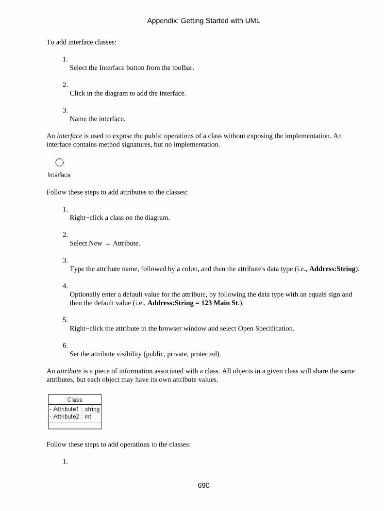
To add interface classes:
1. Select the Interface button from the toolbar.
2. Click in the diagram to add the interface.
3. Name the interface.
An interface is used to expose the public operations of a class without exposing the implementation. Aninterface contains method signatures, but no implementation.
Follow these steps to add attributes to the classes:
1. Right−click a class on the diagram.
2. Select New → Attribute.
3. Type the attribute name, followed by a colon, and then the attribute's data type (i.e., Address:String).
4. Optionally enter a default value for the attribute, by following the data type with an equals sign andthen the default value (i.e., Address:String = 123 Main St.).
5. Right−click the attribute in the browser window and select Open Specification.
6. Set the attribute visibility (public, private, protected).
An attribute is a piece of information associated with a class. All objects in a given class will share the sameattributes, but each object may have its own attribute values.
Follow these steps to add operations to the classes:
1.
Appendix: Getting Started with UML
690

Right−click a class on the diagram.
2. Select New → Operation.
3. Enter the operation signature, including parameters and a return type. Use the formatOpName(Parm1:Parm1DataType, Parm2:Parm2DataType):ReturnType (for example,AddNumbers(X:Int, Y:Int): Long).
4. Right−click the operation in the browser window and select Open Specification.
5. Set the operation visibility (public, private, protected).
An operation is a method within the class. In Rose, you can define the operation name, parameters, visibility,return type, and parameter data types. Certain operations, such as Get() and Set() methods for attributes, canbe automatically generated by Rose.
Web Modeling
Thanks to the recent work of people such as Jim Conallen, UML is now being used more and more frequentlyto model web applications. Rose includes a number of class stereotypes for web modeling, such as clientpages, server pages, and HTML forms.
These web classes are placed on a Class diagram and, like traditional classes, can include attributes,operations, and relationships. Using Class diagrams, you can view the web classes and their interrelationships,and also see how the web classes interact with the other classes in the system.
Before following any of these procedures, select Tools → Options. On the Diagram tab, set the defaultlanguage to Web Modeler.
To add server pages to the model:
1. Select the Server Page class button from the toolbar.
2. Click in the diagram to add the class.
3.
Appendix: Getting Started with UML
691

Name the class.
A server page contains logic that runs on the server, and uses server resources such as database connections,security services, or file services.
To add client pages to the model:
1. Select the Client Page class button from the toolbar.
2. Click in the diagram to add the class.
3. Name the class.
A client page contains logic that runs on the client machine.
Follow these steps to add HTML forms to the model:
1. Select the HTML Form class button from the toolbar.
2. Click in the diagram to add the class.
3. Name the class.
An HTML form represents a simple HTML page and the fields contained within that page.
To add applets to the model:
1. Select the Applet class button from the toolbar.
2.
Appendix: Getting Started with UML
692

Click in the diagram to add the class.
3. Name the class.
An applet is a small application that is downloaded to the client machine and runs on the client.
To add a web application object to the model:
1. Select the Web Application class button from the toolbar.
2. Click in the diagram to add the class.
3. Name the class.
An application is an object that is used to maintain state information, and is shared among all users of anapplication.
Follow these steps to add session objects to the model:
1. Select the Web Session class button from the toolbar.
2. Click in the diagram to add the class.
3. Name the class.
A session object is an object that is used to maintain state information, and is specific to a single client and thecurrent session.
Appendix: Getting Started with UML
693

Follow these steps to add COM objects to the model:
1. Select the COM Object class button from the toolbar.
2. Click in the diagram to add the class.
3. Name the class.
A COM object is an object such as an ActiveX control that uses Microsoft's Component Object Model.
Adding Class Relationships
There are many different types of relationships between classes. An association relationship indicates that oneclass needs to communicate with another. Associations may be unidirectional or bidirectional. An aggregationrelationship suggests a whole/part relationship between two classes. A generalization relationship indicates aparent/child inheritance relationship between two classes. Finally, a dependency relationship is a weaker formof association, suggesting that a change to one class may affect another.
Association names can be added to a relationship to clarify the relationship's purpose. Role names can also beused that show what role each class plays in the relationship. Multiplicity settings show how many instancesof one object are related to a single instance of the other object.
Relationships are drawn on Class diagrams as arrows between the two related classes. Different types ofarrows are used to indicate different types of relationships.
Follow these steps to add association relationships between the classes:
1. Select the Unidirectional Association or the Bidirectional Association toolbar button.
2. Drag an arrow from one class to the other.
3. Type an association name, if needed.
An association relationship is a semantic connection between classes. It indicates that one class needs tocommunicate with another (for example, one class needs to send a message to the other). Unidirectionalassociations suggest that the messages can be sent in only one direction, while bidirectional associationssuggest that messages can be sent in both directions (i.e., each class can call a method of the other).
Appendix: Getting Started with UML
694

To add aggregation relationships:
1. Select the Aggregation toolbar button.
2. Drag an arrow from the "whole" class to the "part" class.
3. Type an association name, if needed.
An aggregation relationship is used to denote a whole/part relationship between classes. In this situation, oneclass logically contains another. Association and aggregation relationships are created identically during codegeneration.
To add generalization relationships:
1. Select the Generalization toolbar button.
2. Drag an arrow from the child class to the parent class.
A generalization relationship is used to show an inheritance relationship between two classes. The child classinherits all attributes, operations, and relationships of the parent.
To add dependency relationships:
1. Select the Dependency toolbar button.
2. Drag an arrow from one class to the other.
A dependency relationship is a weaker form of an association relationship. While one class still needs tocommunicate with the other, neither class is responsible for instantiating, destroying, or otherwise managingthe other. When generating code for an association relationship, a reference to one class is created inside theother through a new attribute. With a dependency relationship, no attributes are created to support therelationship. Dependency relationships must be unidirectional.
Appendix: Getting Started with UML
695

Follow these steps to add multiplicity to the relationships:
1. Right−click one end of the relationship.
2. Select Multiplicity and then the appropriate multiplicity setting for that end of the relationship.
3. Right−click the other end of the relationship and set its multiplicity.
Multiplicity shows how many instances of one class are related to a single instance of another class.Multiplicity indicators are placed at both ends of a relationship to show the number of instances in bothdirections. Multiplicity is not included on a generalization relationship.
To add role names to the relationships:
1. Right−click one end of the relationship.
2. Select Role Name.
3. Type the role name on the diagram.
4. Select the other end of the relationship and set its role name.
Role names indicate what role a class plays in a relationship. For example, in the relationship between Personand Company, a Person could play the role of Employee. Role names are used in the code−generationprocess; when an attribute is created to support a relationship, the attribute is named with the role name.
Building a Statechart Diagram
A Statechart diagram is used to show the dynamic behavior of an object. It shows the various states in whichan object can exist, what state an object is in when it is created, what state an object is in when it is destroyed,
Appendix: Getting Started with UML
696

how an object moves from one state to another, and what an object does when it is in various states. All of thisinformation helps a developer get a complete picture of how a particular object should behave.
Using Rose, you can create one or more Statechart diagrams for a class, and include all of the informationlisted above. Statechart diagrams do not need to be created for every class in a model. Classes with significantdynamic behavior, complex behavior, or behavior that is not well understood among the development teamare good candidates for Statechart diagrams.
Follow these steps to create a Statechart diagram:
1. Right−click a class in the browser.
2. Select New → Statechart Diagram.
3. Name the new diagram.
A Statechart diagram includes the various states, transitions, activities, and actions for an object in aparticular class. Each class can have a single state/activity model, with one or more Statechart diagrams withinit.
To add states to the diagram:
1. Select the Client Page class button from the toolbar.
2. Click in the diagram to add the class.
3. Name the class.
Appendix: Getting Started with UML
697

A state is a condition in which an object can exist. For example, an invoice can be New, Paid, Delinquent, orCanceled. Each of these represents a different state.
To add start and end states:
1. Select the Start State or End State button from the toolbar.
2. Click in the diagram to place the start state or end state.
A start state shows the state an object is in when it is first instantiated. A Statechart diagram has one, and onlyone, start state. A start state is shown as a black dot on the diagram. An end state shows what state an object isin right before it is removed from memory. A Statechart diagram may have zero, one, or more end states. Anend state is shown as a bull's−eye on the diagram.
To add activities to the states:
1. Right−click the state and select Open Specification.
2. Select the Actions tab.
3. Right−click in the white space and select Insert.
4. Double−click the new activity (the word "Entry/" in the list) to open the activity specification.
5. Enter the activity details.
An activity is some bit of processing that occurs while the object is in a particular state. Activities can occurupon entry into the state, while exiting the state, while in the state, or upon a particular event.
To add transitions between the states:
1.
Appendix: Getting Started with UML
698

Select the State Transition button from the toolbar.
2. Drag from one state to another.
3. Right−click the transition.
4. Select Open Specification.
5. Add transition details, such as an event or guard condition.
A transition indicates how an object can move from one state to another. It may include an event, whichtriggers the transition, or a guard condition. An event may also be sent to another object during the transition.A guard condition, which is enclosed in square brackets, controls when the transition may or may not occur.An action on the transition is a small piece of processing that occurs during the transition itself. The formatfor these items on a transition line is:
Event(Arguments) [Guard] /Action ^SendEventTarget.SendEvent(Arguments)
Building a Component Diagram
A Component diagram is used to model the physical components in your system: source code files, executablefiles, DLL files, ActiveX objects, and so on. Using a Component diagram, the team can specify whatcomponents exist and what their relationships are to each other.
This exercise is especially helpful in optimizing the design and planning for deployment. By mapping eachcomponent to its appropriate architectural layer (database, business logic, presentation, etc.), the team can seethe interaction between the layers themselves. The team can analyze and optimize the communicationbetween the layers before coding is complete.
Rose supports a number of different component stereotypes, such as the ones mentioned above.
To create a new Component diagram:
1. Right−click a package in the Component view of the browser.
2. Select New → Component Diagram.
3. Name the new diagram.
Appendix: Getting Started with UML
699

A Component diagram is used to show a subset of the components or packages of components in the systemand their relationships.
Follow these steps to add components to the model:
1. Select the Component button from the toolbar.
2. Click in the diagram to add the component.
3. Name the component.
4. Right−click the component.
5. Select Open Specification.
6. Set the component stereotype and language.
7. Select the Realizes tab.
8. Right−click each class that will be contained within the component, and select Assign. You may alsodrag the classes in the browser from the Logical view to the appropriate component in the Componentview.
A component is one of the physical files that make up a system. Source code components will realize many ofthe various classes contained within the model.
Appendix: Getting Started with UML
700

Building a Deployment Diagram
Deployment diagrams illustrate the physical distribution of a system. A given project has one, and only one,Deployment diagram. These diagrams show the processors, devices, connections, and processes involved inthe system.
Processors are machines on the network with processing power, including servers and workstations. They donot include printers and other such devices. Processors run processes (executable code).
Follow these steps to create the Deployment diagram:
1. Double−click the Deployment view.
2. Select the Processor toolbar button.
3. Click the Deployment diagram to place the processor.
4. Name the processor.
5. Right−click on the processor and select New → Process from the menu.
6. Name the process.
Devices are the other machines on the network. They include printers, scanners, dumb terminals, and backupdevices.
Appendix: Getting Started with UML
701

To add devices to the diagram:
1. Select the Device toolbar button.
2. Click the Deployment diagram to place the device.
3. Name the device.
Connections are physical links between processors and other processors, devices and other devices, orprocessors and devices. Connections can be physical network connections or virtual connections—across theInternet, for example.
To add connections to the diagram:
1. Select the Connection toolbar button.
2. Click on one processor or device to be connected.
3. Drag the connection to the other processor or device to be connected.
4. Name the connection.
Appendix: Getting Started with UML
702