table top type robot tt - iai-robot.co.jp · table top type robot tt ... model no. example tt -...
TRANSCRIPT

Table Top Type Robot TT First Step Guide Second Edition
Thank you for purchasing our product. Make sure to read the Safety Guide and detailed Instruction Manual (CD) included with the product in addition to this First Step Guide to ensure correct use. This Instruction Manual is original.
• Using or copying all or part of this Instruction Manual without permission is prohibited. • The company names, names of products and trademarks of each company shown in the
sentences are registered trademarks.
Product Check This product is comprised of the following parts if it is of standard configuration. If you find any fault in the contained model or any missing parts, contact us or our distributor. 1. Parts (The option is excluded.) No. Part Name Model
1 Robot Main Body (with a built-in controller)
Refer to “How to read the model plate” and “How to read the model of the controller.”
Accessories 2 Power Supply Plug AP-400-C (Manufacturer: Yamate Electric Co., Ltd.) 3 I/O Flat Cable CB-DS-PIO020 4 First Step Guide 5 Operation Manual (CD) 6 Safety Guide
2. Optional Components No. Part Name Model
1 Main Body Mounting Bracket (with set bolts and nuts) TT-FT
3. Teaching Tool (Option) The personal computer application software or teaching pendant is required for the operations including program creation and setup such as position setting and parameter setting with teaching. Use either of them.
No. Part Name Model Remarks
1 PC Software (with RS232C Cable + Emergency Stop Box) IA-101-X-MW RS232C→RS232C*1
2 PC Software (USB conversion adapter + RS232C cable + Cable and Emergency Stop Box)
IA-101-X-USBMW USB→RS232C*1
3 PC Software (with USB Cable + Dummy Plug) IA-101-TT-USB USB→USB*1 4 Teaching pendant SEL-T -
5 Teaching pendant (with deadman switch) SEL-TD -
6 Teaching pendant IA-T-X -
7 Teaching pendant (with deadman switch) IA-T-XD - *1 The communication port on the left is for the personal computer and on the right is for
the TT. 4. Operation manuals related to this product, which are contained in the CD.
No. Name Manual No. 1 Table Top Type Robot TT Operation Manual ME0149 2 PC software IA-101-X-MW Operation Manual ME0154 3 Teaching pendant SEL-T/TD Operation Manual ME0183 4 Teaching pendant IA-T-X/XD Operation Manual ME0160 5 DeviceNet Operation Manual ME0124 6 CC-Link Operation Manual ME0123 7 PROFIBUS-DP Operation Manual ME0153 8 X-SEL Ethernet Operation Manual ME0140
5. How to read the model plate
6. How to read the Model No. Model No. Example TT - A3 - I - 2020 - 05B - DV
① ② ③ ④ ⑤ ⑥ ①Series ②Type ③Encoder type ④XY Stroke ⑤Z Stroke ⑥Option
A2:Gate Type with 2-axis
C2:Cantilever Type with 2-axis
-
TT (Normal) A3:Gate Type with
3-axis C3:Cantilever Type
with 2-axis
I: Incremental
2020 200×200mm 4040 400×400mm
05B 50mm
10B 100mm
DV :DeviceNet SpecificationsCC :CC-Link Specifications PR :PROFIBUS SpecificationsET :Ethernet SpecificationsFT :Main Body Mounting
Bracket included P :I/O PNP Specifications
Basic Specifications [Common Specifications]
Item Specifications Surrounding air temperature・humidity 0 to 40°C, Room Humidity 20% to 85% or lessMotor Type Pulse Motor (Servo Control) Position detection method Incremental EncoderDriving System Ball Screw (φ10mm, Rolled C10), Ball Screw Lead 6mmPositioning Repeatability ± 0.02mm Backlash 0.1mm or less Guide Direct Driven Infinite Circulation TypeAllowable Load Moment*1 Ma:6•5N•m Mb:9.3N•m Mc:16.4N•m
*1 Value found on the assumption of the life of 5000 km run [Individual Mechanism Specifications]
Stroke (mm)Max. Speed for
each axes (mm/sec)
Max. Load Capacity (kg)*2
Type X
Axis Y
AxisZ
AxisX
AxisY
AxisZ
Axis
Acceleration/Deceleration
(G) X Axis
Y Axis
Z Axis
Weight(kg) Model
200 200 - 14.8 TT-A2-I-2020 2-axis 400 400 -
300 0.3 10 5 - 33 TT-A2-I-4040
50 300 280 TT-A3-I-2020-05B200 200100 300
16.5 TT-A3-I-2020-10B
50 300 280 TT-A3-I-4040-05B
Gate Type with 3-axis
400 400100 300
0.3 10 - 2 35
TT-A3-I-4040-10B200 200 - 16.3 TT-C2-I-2020 2-axis 400 400 -
300 0.2 - 4 - 35 TT-C2-I-4040
50 300 280 TT-C3-I-2020-05B200 200100 300
18 TT-C3-I-2020-10B
50 300 280 TT-C3-I-4040-05B
Cantilever Type with 3-axis
400 400100 300
0.2 - - 2 37
TT-C3-I-4040-10B*2 The load capacity in the case of rated acceleration is shown (Gate Type: 0.3G, Cantilever Type: 0.2G) [Controller Specifications]
Item Specifications Number of axes 2-axis 3-axis
Supply voltage Single-phase 100 to 115VAC, 200 to 230VAC ± 10% Power frequency 50Hz/60Hz
100VAC 150VA 210VA Power-source capacity 200VAC 155VA 215VA Maximum Current*3 3A (100VAC), 1.6A (200VAC) 4.2A (100VAC), 2.2A (200VAC)Rush Current*4 15A (100VAC), 30A (200VAC) Leakage Current 0.75mA Insulation Strength 2000VAC for 1 min. Momentary Power Interruption Tolerance 500μs or more Speed Setting 1 to 300mm/sec Acceleration Setting 0.01G to 0.3G Program language Super SEL language Number of programs (Number of multitask programs) 64 programs (16 programs) Number of program steps 6000 steps (Total) Number of positions 3000 positions (Total) Program Startup Special Digital Switch + Special Start Switch Data storage device Flash ROM + SRAM*5 Standard I/O Board 16 Input Points / 16 Output Points Applicable Field Bus DeviceNet / CC-Link / PROFIBUS / Ethernet Protective functions Over-voltage, motor over current, motor overload, driver temperature
abnormality, encoder abnormality, etc. *3 The current reaches its maximum level when the servo-motor exciting phase is detected which is to be
performed in the first servo-motor turning ON processing after the power injection. (Normal: Approx. 1 to 2 sec, Max.: 10 sec)
*4 Rush current at the power connection continues for about 20 msec. Consider the safety rate at the time when rush current passes. The rush current value varies depending on the impedance of the power line.
*5 The SRAM data is not battery backed up. Accordingly, when the power is turned off, the data of flags and variables used in the program, are not saved. Take the greatest care. The same procedure is applied when the program or position data is not written on the Flash ROM.
External Dimensions [Gate Type with 2-axis TT-A2] *1 Fine slider adjustment (for manual tweaking of position).
(Unit mm) Model A B C D E F G Xst Yst
TT-A2-I-2020 369.7 330 338.5 133.3 185 240 88.2 200 200TT-A2-I-4040 569.7 530 538.5 333.3 385 440 188.2 400 400
[Gate Type with 3-axis TT-A3] *1 Fine slider adjustment (for manual tweaking of position).
(Unit mm) Model A B C D E F Xst Yst Zst
TT-A3-I-2020-05B 369.7 330 338.5 83.3 135 240 200 200 50 TT-A3-I-2020-10B 369.7 330 338.5 83.3 135 240 200 200 100TT-A3-I-4040-05B 569.7 530 538.5 283.3 335 440 400 400 50 TT-A3-I-4040-10B 569.7 530 538.5 283.3 335 440 400 400 100
Model
Serial number
Warning : Operation of this equipment requires detailed installation and operation instructions which are provided on the CD included in the box this device was packaged in. It should be retained with this device at all times.
A copy of the CD Manual can be requested by contacting your nearest IAI Sales Office listed at the back cover of the Instruction Manual or on the First Step Guide.

[Cantilever Type with 2-axis TT-C2] *1 Fine slider adjustment (for manual tweaking of position).
(Unit mm) Model A B C D E F Xst Yst
TT-C2-I-2020 405 320 135 120 310 42 200 200 TT-C2-I-4040 605 520 335 213.6 510 142 400 400
[Cantilever Type with 3-axis TT-C3] *1 Fine slider adjustment (for manual tweaking of position).
(Unit mm) Model A B C D E F Xst Yst Zst
TT-C3-I-2020-05B 405 330.6 135 120 310 71 200 200 50 TT-C3-I-2020-10B 405 330.6 135 120 310 71 200 200 100 TT-C3-I-4040-05B 605 530.6 335 213.6 510 171 400 400 50 TT-C3-I-4040-10B 605 530.6 335 213.6 510 171 400 400 100
Installation Environment Do not use this product in the following environment:
• Location where the surrounding air temperature exceeds the range of 0 to 40°C • Location where condensation occurs due to abrupt temperature changes • Relative humidity less than 20%RM or greater than 85%RM • Location exposed to corrosive gases or combustible gases • Location exposed to significant amount of dust, salt or iron powder • Location subject to direct vibration or impact • Location exposed to direct sunlight • Location where the product may come in contact with water, oil or chemical droplets
When using the product in any of the locations specified below, provide a sufficient shield.
• Location subject to electrostatic noise • Location where high electrical or magnetic field is present • Location with the mains or power lines passing nearby
Installation and Noise Elimination 1. There is a cooling vent hole on the main body’s rear panel section. Do not close the vent
hole when the main body is installed.
2. When it required to fix the main body, fix it as follows using the optional mounting brackets (Model TT-FT: 4 sets with secure bolts and nuts) User supplied bolts to secure the brackets to the mounting surface or table.
3. Protective Ground
4. Noise Elimination Grounding (Frame Ground) Connect it using a soft copper wire with the diameter of 1.6 mm or more to the frame ground on the main body (Refer to the above figure). Do not share the ground wire with or connect to other equipment. Ground each controller. The same procedure is applied for the protective ground.
5. Precautions Regarding wiring Method
Separate the I/O cable, communication line and power / driving cable each other. 6. Noise Sources and Elimination
Carry out noise elimination measures for power devices on the same power path and in the same equipment. The following are examples of measures to eliminate noise sources: ①AC solenoid valves, magnet switches and relays
[Measure] Install a Noise killer parallel with the coil.
②DC solenoid valves, magnet switches and relays [Measure] Install a diode parallel with the coil.
Use a DC relay with a built-in diode.
Table Top TT Table Top TTOther equipment Other equipment Other equipment
Noise killer
+24V
+24V
0V
0V
Relaycoil
Relay coil
R
C
4-M4 Depth 8
2- φ 4H7 Depth 5
Zst
Home
Zst +
147
.8
CA
Xst
Yst
Home
2-φ4H7 Depth 54-M5 Depth 10
4-M4 Depth 8
D
Z Axis
Zst +
49.8
(Cable Projection Length)
EB
F
7.3
4.3
4.3
1.8
37.430
30 42 50
13.630
2.5SEME ME
2.5
2.5
26
SE
6040
50 40
84 2.5 ME
5051
.82.
5 ME
2.5
46
SE
ME
41.8
148.830 45 45 1.2
49
50605
1042
22317
156
858
1058
124.
51.
5
10.6(44)
50
37.4
Z-Slider Set Hole Section
4-M5 Depth 10
Y-Slider Position Adjusting Volume*1
T-Groove Section
T-Groove(Four Locations)
Home
Z-Slider Position Adjusting Volume*1
Z-Slider Position Adjusting Volume*1
X Axis
Y Axis
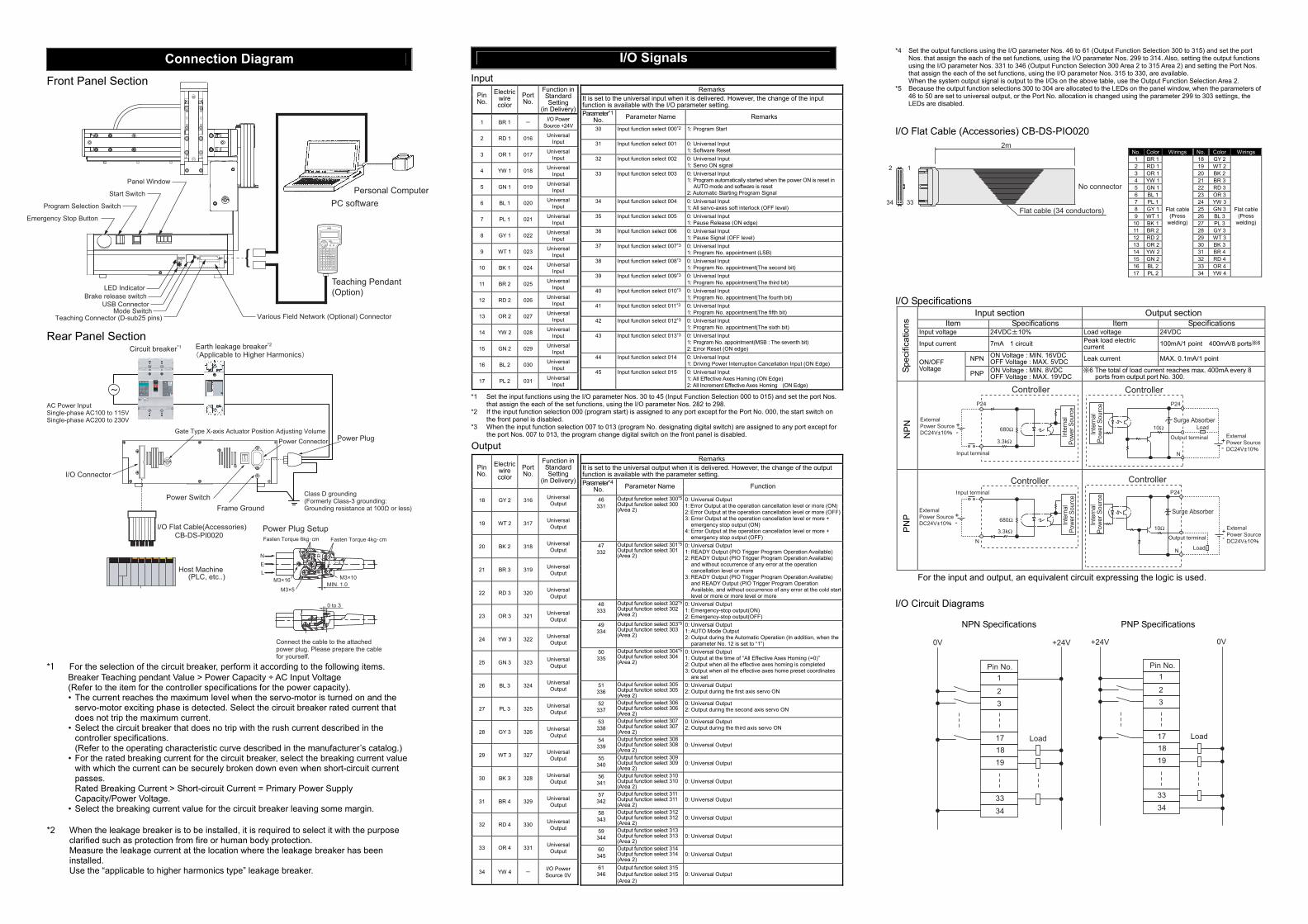
Connection Diagram
Front Panel Section Rear Panel Section *1 For the selection of the circuit breaker, perform it according to the following items.
Breaker Teaching pendant Value > Power Capacity ÷ AC Input Voltage (Refer to the item for the controller specifications for the power capacity). • The current reaches the maximum level when the servo-motor is turned on and the
servo-motor exciting phase is detected. Select the circuit breaker rated current that does not trip the maximum current.
• Select the circuit breaker that does no trip with the rush current described in the controller specifications. (Refer to the operating characteristic curve described in the manufacturer’s catalog.)
• For the rated breaking current for the circuit breaker, select the breaking current value with which the current can be securely broken down even when short-circuit current passes. Rated Breaking Current > Short-circuit Current = Primary Power Supply Capacity/Power Voltage.
• Select the breaking current value for the circuit breaker leaving some margin.
*2 When the leakage breaker is to be installed, it is required to select it with the purpose clarified such as protection from fire or human body protection. Measure the leakage current at the location where the leakage breaker has been installed. Use the “applicable to higher harmonics type” leakage breaker.
I/O Signals Input *1 Set the input functions using the I/O parameter Nos. 30 to 45 (Input Function Selection 000 to 015) and set the port Nos.
that assign the each of the set functions, using the I/O parameter Nos. 282 to 298. *2 If the input function selection 000 (program start) is assigned to any port except for the Port No. 000, the start switch on
the front panel is disabled. *3 When the input function selection 007 to 013 (program No. designating digital switch) are assigned to any port except for
the port Nos. 007 to 013, the program change digital switch on the front panel is disabled.
Output
*4 Set the output functions using the I/O parameter Nos. 46 to 61 (Output Function Selection 300 to 315) and set the port Nos. that assign the each of the set functions, using the I/O parameter Nos. 299 to 314. Also, setting the output functions using the I/O parameter Nos. 331 to 346 (Output Function Selection 300 Area 2 to 315 Area 2) and setting the Port Nos. that assign the each of the set functions, using the I/O parameter Nos. 315 to 330, are available. When the system output signal is output to the I/Os on the above table, use the Output Function Selection Area 2.
*5 Because the output function selections 300 to 304 are allocated to the LEDs on the panel window, when the parameters of 46 to 50 are set to universal output, or the Port No. allocation is changed using the parameter 299 to 303 settings, the LEDs are disabled.
I/O Flat Cable (Accessories) CB-DS-PIO020
No. Color Wirings No. Color Wirings 1 BR 1 18 GY 22 RD 1 19 WT 23 OR 1 20 BK 24 YW 1 21 BR 35 GN 1 22 RD 36 BL 1 23 OR 37 PL 1 24 YW 38 GY 1 25 GN 39 WT 1 26 BL 310 BK 1 27 PL 311 BR 2 28 GY 312 RD 2 29 WT 313 OR 2 30 BK 314 YW 2 31 BR 415 GN 2 32 RD 416 BL 2 33 OR 417 PL 2
Flat cable(Press
welding)
34 YW 4
Flat cable(Press
welding)
I/O Specifications
Input section Output section Item Specifications Item Specifications
Input voltage 24VDC±10% Load voltage 24VDC
Input current 7mA 1 circuit Peak load electric current 100mA/1 point 400mA/8 ports※6
NPN ON Voltage : MIN. 16VDC OFF Voltage : MAX. 5VDC Leak current MAX. 0.1mA/1 point
ON/OFF Voltage
PNP ON Voltage : MIN. 8VDC OFF Voltage : MAX. 19VDC
※6 The total of load current reaches max. 400mA every 8 ports from output port No. 300.
For the input and output, an equivalent circuit expressing the logic is used. I/O Circuit Diagrams NPN Specifications PNP Specifications
Pin No.
Electric wire color
Port No.
Function in Standard Setting
(in Delivery)
1 BR 1 - I/O Power Source +24V
2 RD 1 016 Universal Input
3 OR 1 017 Universal Input
4 YW 1 018 Universal Input
5 GN 1 019 Universal Input
6 BL 1 020 Universal Input
7 PL 1 021 Universal Input
8 GY 1 022 Universal Input
9 WT 1 023 Universal Input
10 BK 1 024 Universal Input
11 BR 2 025 Universal Input
12 RD 2 026 Universal Input
13 OR 2 027 Universal Input
14 YW 2 028 Universal Input
15 GN 2 029 Universal Input
16 BL 2 030 Universal Input
17 PL 2 031 Universal Input
Remarks It is set to the universal input when it is delivered. However, the change of the input function is available with the I/O parameter setting. Parameter*1
No. Parameter Name Remarks
30 Input function select 000*2 1: Program Start
31 Input function select 001 0: Universal Input 1: Software Reset
32 Input function select 002 0: Universal Input 1: Servo ON signal
33 Input function select 003 0: Universal Input 1: Program automatically started when the power ON is reset in
AUTO mode and software is reset 2: Automatic Starting Program Signal
34 Input function select 004 0: Universal Input 1: All servo-axes soft interlock (OFF level)
35 Input function select 005 0: Universal Input 1: Pause Release (ON edge)
36 Input function select 006 0: Universal Input 1: Pause Signal (OFF level)
37 Input function select 007*3 0: Universal Input 1: Program No. appointment (LSB)
38 Input function select 008*3 0: Universal Input 1: Program No. appointment(The second bit)
39 Input function select 009*3 0: Universal Input 1: Program No. appointment(The third bit)
40 Input function select 010*3 0: Universal Input 1: Program No. appointment(The fourth bit)
41 Input function select 011*3 0: Universal Input 1: Program No. appointment(The fifth bit)
42 Input function select 012*3 0: Universal Input 1: Program No. appointment(The sixth bit)
43 Input function select 013*3 0: Universal Input 1: Program No. appointment(MSB : The seventh bit) 2: Error Reset (ON edge)
44 Input function select 014 0: Universal Input 1: Driving Power Interruption Cancellation Input (ON Edge)
45 Input function select 015 0: Universal Input 1: All Effective Axes Homing (ON Edge) 2: All Increment Effective Axes Homing (ON Edge)
Pin No.
Electric wire color
Port No.
Function in Standard Setting
(in Delivery)
18 GY 2 316 Universal Output
19 WT 2 317 Universal Output
20 BK 2 318 Universal Output
21 BR 3 319 Universal Output
22 RD 3 320 Universal Output
23 OR 3 321 Universal Output
24 YW 3 322 Universal Output
25 GN 3 323 Universal Output
26 BL 3 324 Universal Output
27 PL 3 325 Universal Output
28 GY 3 326 Universal Output
29 WT 3 327 Universal Output
30 BK 3 328 Universal Output
31 BR 4 329 Universal Output
32 RD 4 330 Universal Output
33 OR 4 331 Universal Output
34 YW 4 - I/O Power Source 0V
Remarks It is set to the universal output when it is delivered. However, the change of the output function is available with the parameter setting. Parameter*4
No. Parameter Name Function
46 331
Output function select 300*5Output function select 300(Area 2)
0: Universal Output 1: Error Output at the operation cancellation level or more (ON) 2: Error Output at the operation cancellation level or more (OFF)3: Error Output at the operation cancellation level or more +
emergency stop output (ON) 4: Error Output at the operation cancellation level or more +
emergency stop output (OFF) 47 332
Output function select 301*5Output function select 301 (Area 2)
0: Universal Output 1: READY Output (PIO Trigger Program Operation Available) 2: READY Output (PIO Trigger Program Operation Available)
and without occurrence of any error at the operation cancellation level or more
3: READY Output (PIO Trigger Program Operation Available) and READY Output (PIO Trigger Program Operation Available, and without occurrence of any error at the cold start level or more or more level or more
48 333
Output function select 302*5Output function select 302(Area 2)
0: Universal Output 1: Emergency-stop output(ON) 2: Emergency-stop output(OFF)
49 334
Output function select 303*5Output function select 303(Area 2)
0: Universal Output 1: AUTO Mode Output 2: Output during the Automatic Operation (In addition, when the
parameter No. 12 is set to “1”) 50 335
Output function select 304*5Output function select 304(Area 2)
0: Universal Output 1: Output at the time of “All Effective Axes Homing (=0)” 2: Output when all the effective axes homing is completed 3: Output when all the effective axes home preset coordinates
are set 51 336
Output function select 305Output function select 305 (Area 2)
0: Universal Output 2: Output during the first axis servo ON
52 337
Output function select 306Output function select 306 (Area 2)
0: Universal Output 2: Output during the second axis servo ON
53 338
Output function select 307Output function select 307 (Area 2)
0: Universal Output 2: Output during the third axis servo ON
54 339
Output function select 308Output function select 308(Area 2)
0: Universal Output
55 340
Output function select 309Output function select 309 (Area 2)
0: Universal Output
56 341
Output function select 310Output function select 310(Area 2)
0: Universal Output
57 342
Output function select 311 Output function select 311 (Area 2)
0: Universal Output
58 343
Output function select 312Output function select 312(Area 2)
0: Universal Output
59 344
Output function select 313Output function select 313(Area 2)
0: Universal Output
60 345
Output function select 314Output function select 314 (Area 2)
0: Universal Output
61 346
Output function select 315Output function select 315(Area 2)
0: Universal Output
Spec
ifica
tions
N
PN
P
NP
Teaching Pendant(Option)
Emergency Stop Button
Program Selection Switch
Start Switch
Panel Window
LED IndicatorBrake release switch
USB ConnectorMode Switch
Teaching Connector (D-sub25 pins) Various Field Network (Optional) Connector
Personal ComputerPC software
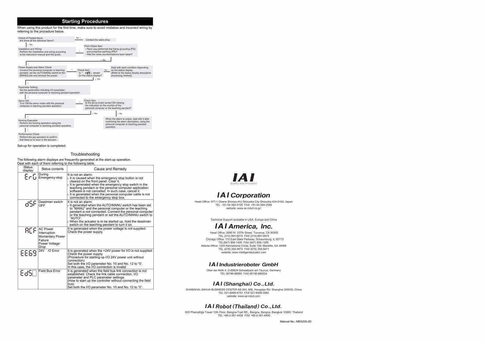
Starting Procedures When using this product for the first time, make sure to avoid mistakes and incorrect wiring by referring to the procedure below. Set-up for operation is completed.
Troubleshooting
The following alarm displays are frequently generated at the start-up operation. Deal with each of them referring to the following table.
Status display Status contents Cause and Remedy
During Emergency-stop
It is not an alarm. • It is caused when the emergency stop button is not
cleared on the front panel. Clear it. • It is generated when the emergency stop switch in the
teaching pendant or the personal computer application software is not cancelled. In such case, cancel it.
• It is generated when the personal computer cable is not connected to the emergency stop box.
Deadman switch OFF
It is not an alarm. • It generated when the AUTO/MANU switch has been set
to “MANU” and the personal computer or the teaching pendant is not connected. Connect the personal computer or the teaching pendant or set the AUTO/MANU switch to “AUTO”.
• When the actuator is to be started up, hold the deadman switch on the teaching pendant to turn it on.
AC Power Interruption Momentary Power Failure Power Voltage Drop
It is generated when the power voltage is not supplied. Check the power supply.
24V /O Error It is generated when the +24V power for I/O is not supplied. Check the power supply. (Procedure for starting up I/O 24V power unit without connection) Set both the I/O parameter No. 10 and No. 12 to “0”. In this case, the I/O connection is invalid.
Field Bus Error It is generated when the field bus link connection is not established. Check the link cable connection, I/O parameter and PLC parameter settings. (How to start up the controller without connecting the field bus) Set both the I/O parameter No. 10 and No. 12 to “0”.
Head Office: 577-1 Obane Shimizu-KU Shizuoka City Shizuoka 424-0103, JapanTEL +81-54-364-5105 FAX +81-54-364-2589
website: www.iai-robot.co.jp/
Ober der Röth 4, D-65824 Schwalbach am Taunus, GermanyTEL 06196-88950 FAX 06196-889524
SHANGHAI JIAHUA BUSINESS CENTER A8-303, 808, Hongqiao Rd. Shanghai 200030, ChinaTEL 021-6448-4753 FAX 021-6448-3992
website: www.iai-robot.com
Technical Support available in USA, Europe and China
Head Office: 2690 W. 237th Street, Torrance, CA 90505TEL (310) 891-6015 FAX (310) 891-0815
Chicago Office: 110 East State Parkway, Schaumburg, IL 60173TEL(847) 908-1400 FAX (847) 908-1399
TEL (678) 354-9470 FAX (678) 354-9471website: www.intelligentactuator.com
Atlanta Office: 1220 Kennestone Circle, Suite 108, Marietta, GA 30066
825 PhairojKijja Tower 12th Floor, Bangna-Trad RD., Bangna, Bangna, Bangkok 10260, ThailandTEL +66-2-361-4458 FAX +66-2-361-4456
Manual No.: ME0205-2D