tachimetro programmabile a 6 cifre … · deft conferma dell’operazione di default eseguita....
TRANSCRIPT
TCH700
AITAELECTRONICS APPARATI ELETTRONICI INDUSTRIALI
Prodotto conforme ai requisiti essenziali delle di-rettive CEE relativi alla compatibilità elettroma-gnetica e sicurezza elettrica. Product in accordance to the requirements of the CEE directives relative to the electromagnetic compatibility and electric safety.
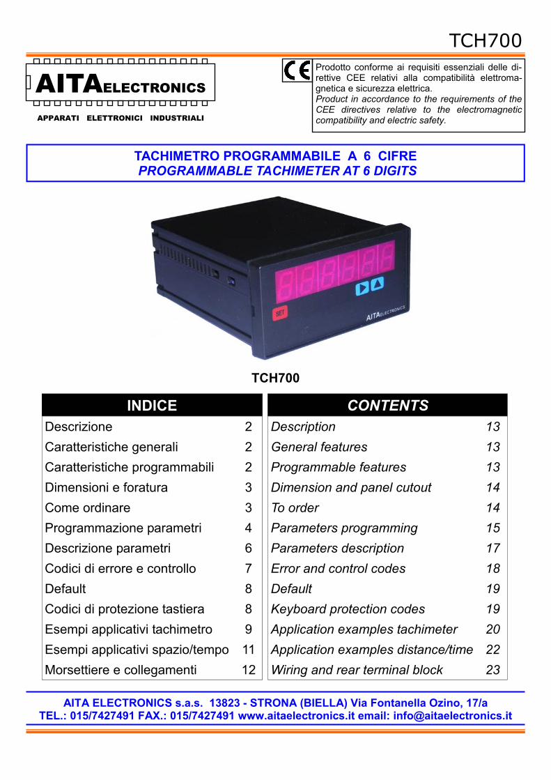
TACHIMETRO PROGRAMMABILE A 6 CIFRE PROGRAMMABLE TACHIMETER AT 6 DIGITS
AITA ELECTRONICS s.a.s. 13823 - STRONA (BIELLA) Via Fontanella Ozino, 17/a TEL.: 015/7427491 FAX.: 015/7427491 www.aitaelectronics.it email: [email protected]
TCH700
Descrizione 2 Caratteristiche generali 2 Caratteristiche programmabili 2 Dimensioni e foratura 3 Come ordinare 3 Programmazione parametri 4 Descrizione parametri 6
INDICE
Esempi applicativi spazio/tempo 11
Codici di errore e controllo 7 Default 8
Esempi applicativi tachimetro 9 Codici di protezione tastiera 8
Morsettiere e collegamenti 12
Description 13 General features 13 Programmable features 13 Dimension and panel cutout 14 To order 14 Parameters programming 15 Parameters description 17
CONTENTS
Application examples distance/time 22
Error and control codes 18 Default 19
Application examples tachimeter 20 Keyboard protection codes 19
Wiring and rear terminal block 23

TCH700
2
TCH700 è un tachimetro programmabile a microcontrollore in grado di elaborare una frequenza in ingresso e visualizzare un valore numerico qualsiasi dipendente dalla stessa e dai parametri impostati.
Abbiamo predisposto alcuni parametri per adattare il valore da visualizzare al se-gnale in ingresso. Vi rimandiamo alle pagine 6,7 per una precisa descrizione.
• Numero cifre visualizzabili: 4,5,6 (PAR01). • Visualizzazione o no degli zeri non significativi (PAR02). • Posizione virgola (PAR03). • Visualizzazione con segno o no (PAR05). • Protezione tastiera per accesso programmazione (PAR06). • Opzione basse frequenze (PAR10). • Opzione spazio/tempo (PAR11). • Tipo ingresso (PAR12). • Primo parametro di fattorizzazione (PAR17). • Secondo parametro di fattorizzazione (PAR18). • Configurazione seriale (PAR19 per modelli dotati di interfaccia seriale).
• Alimentazione: 20÷30Vac/dc o 85÷265Vac (altre a richiesta). • Alimentazione ausiliaria: disponibile sui morsetti in uscita per alimentare eventua-
li dispositivi esterni di 12Vdc 70mA max. • Impedenza dell’ingresso: 3 Kohm. • Uscite: nessuna. • Tecnica di misura: conteggio e calcolo a microprocessore. • Programmabilità: tramite i tasti presenti sul pannello frontale. • Memoria: utilizzo di memoria interna non volatile (EEPROM). • Visualizzazione: 0.00001÷999999. • Dispositivi collegabili: NAMUR 2 fili, PNP/NPN 3 fili, ENCODER PNP/NPN, ecc.. • Frequenza max: 10 KHz aggiornamento ogni 0,5 sec. • Frequenza min: 0,2 Hz aggiornamento ogni 0,5 sec. • Frequenza min: 0,02 Hz aggiornamento ogni 2,5 sec. con opzione inserita. • Display: 6 cifre, led arancio da 13 mm. • Grado di protezione frontale: IP65. • Ogni indicatore viene fornito completo di morsettiera estraibile, fissaggi per mon-
taggio a pannello e relative istruzioni di collegamento e programmazione. • Dim.: 48 mm x 96 mm profondità 90 mm (morsettiere estraibili comprese).
CARATTERISTICHE PROGRAMMABILI
CARATTERISTICHE GENERALI
DESCRIZIONE

TCH700
3
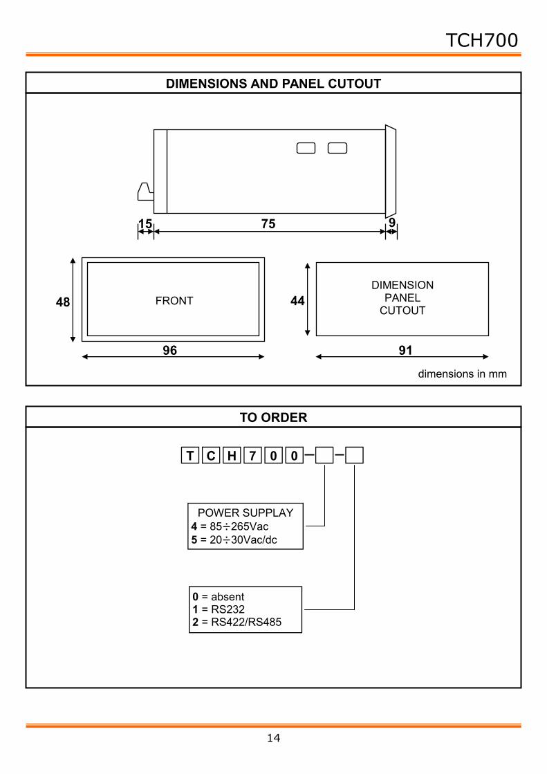
15 75 9
96
48 44
91
quote espresse in mm
FRONTALE QUOTE
FORATURA PANNELLO
ALIMENTAZIONE 4 = 85÷265Vac 5 = 20÷30Vac/dc
T C H 7 0 0
0 = seriale assente 1 = RS232 2 = RS422/RS485
COME ORDINARE
DIMENSIONI E FORATURA PANNELLO

TCH700
4
Per accedere alla programmazione bisogna agire sui pulsanti presenti sul pan-nello frontale a seconda del livello di protezione tastiera che è stato impostato nel PAR06. Esistono due tipi di parametri, a singola cifra ed a più cifre. I primi parametri a cui si accede sono a singola cifra e sono i parametri 01,02,03,04,05,06,10,11,12. I successivi sono a più cifre e sono i parametri 17,18,19.
SET
Premere “SET” + “▲” per l’impostazione del codice “3409” per accedere alla programmazione. Premere “▲” per incrementare la cifra lampeggiante o “►” per passare alla cifra successiva. Composto il codice “3409” premere “SET” per accedere alla programmazione. Se per 10 secondi non si premono i tasti o si imposta un codice non corretto, lo strumento non entrerà in programmazione e riprenderà il funzionamento normale.
AITAELECTRONICS
AITAELECTRONICS
N° PARAMETRO 01,02,03,ecc….
VALORE 1,2,ecc... SPENTO
SPENTO
SPENTO
Premere “▲” per incrementare il valore. Premere “SET” per memorizzare il valore impostato nel parametro visualizzato. Premere “►” per passare al parametro successivo. Giunti al parametro 12 si passerà automaticamente al parametro 17.
▲ ►
SET ▲ ►
PAR06 = 0 PAR06 = 1,2,3
Premere “SET” + “▲” per accedere
alla programmazione
PROGRAMMAZIONE PARAMETRI

TCH700
5
Quando è visualizzato il valore del parametro: Premere “►”, la prima cifra a sinistra inizierà a lampeggiare. Premere “▲” per incrementare la cifra che lampeggia. Premere “►” per passare alla cifra successiva. Premere “▲” + “►” per azzerare l’intero valore. Premere “SET” per memorizzare il valore impostato nel parametro visualizzato.
N.B.: alla fine della programmazione e ad ogni accensione, lindicatore esegue un controllo sui dati impostati e se individua un dato non previsto, visualizza un mes-saggio di errore indicato a pag. 7. Bisogna eseguire una programmazione per cor-reggere i dati errati premendo “SET”. Alla fine della programmazione e di messa a punto dell’indicatore, si racco-manda di inserire il massimo livello di protezione tastiera nel “PAR06”.
AITAELECTRONICS
N° PARAMETRO 17,18,19,ecc….
SPENTO
SPENTO
SPENTO
Quando è visualizzato il numero del parametro (17,18,19): Premere “SET” per memorizzare il valore impostato nel parametro visualizzato. Premere “►” per passare al parametro successivo. Giunti al parametro 19, la successiva pressione sul tasto “►” determinerà la fine della programmazione e l’inizio del funzionamento normale.
I successivi parametri, 17, 18, 19, sono a più cifre e quindi il numero del parametro verrà visualizzato alternativamente al suo valore.
SPENTO
AITAELECTRONICS
VALORE DEL PARAMETRO
SET ▲ ►
SET ▲ ►

TCH700
6
NUMERO PARAMETRO VALORI DESCRIZIONE 01 4,5,6
(4) Cifre visualizzate: 4 = saranno visualizzate 4 cifre 5 = saranno visualizzate 5 cifre 6 = saranno visualizzate 6 cifre
02 0,1 (0)
Visualizzazione zeri non significativi: 0 = visualizzati es.: 005.67 1 = non visualizzati es.: 5.67
03 0,1,2,3,4,5 (0)
Posizione virgola: 0 = es.: 000001 1 = es.: 00001.2 2 = es.: 0001.23 3 = es.: 001.234 4 = es.: 01.2345 5 = es.: 1.23456
05 0,1 (0)
Visualizzazione: 0 = relativa con segno. 1 = assoluta senza segno.
06 0,1,2,3 (0)
Protezione tastiera: 0 = nessuna protezione. 1 = possibile solo l’inserimento del set-point (nei modelli provvisti). 2 = possibile solo l’inserimento del set-point (nei modelli provvisti) con codice di accesso. 3 = protezione totale.
10 0,1 (0)
Opzione bassa frequenza: 0 = frequenza min. 0,2 Hz. 1 = frequenza min. 0,02 Hz.
11 0,1 (0)
Opzione spazio/tempo: 0 = tachimetro. 1 = spazio/tempo.
12 0,1 (0)
Tipo ingresso: 0 = PNP, NAMUR, PUSH-PULL (livello alto attivo). 1 = NPN, OPEN COLLECTOR, PUSH-PULL (livello basso attivo).
N.B.: tra parentesi è indicato il valore di fabbrica (default).
DESCRIZIONE PARAMETRI SINGOLI

TCH700
7
CODICE VISUALIZZATO
DESCRIZIONE COSA FARE
EE01 Errore nel Parametro 01 Riprogrammare.
EE02 Errore nel Parametro 02 Riprogrammare.
EE03 Errore nel Parametro 03 Riprogrammare.
EE05 Errore nel Parametro 05 Riprogrammare.
EE06 Errore nel Parametro 06 Riprogrammare.
EE10 Errore nel Parametro 10 Riprogrammare.
EE11 Errore nel Parametro 11 Riprogrammare.
EE17 Errore nel Parametro 17 Riprogrammare.
EE18 Errore nel Parametro 18 Riprogrammare.
EE19 Errore nel Parametro 19 Riprogrammare.
HHHH Il valore misurato supera la capacità del visualizza-tore.
Aumentare il numero di cifre da vi-sualizzare.
dEFt Conferma dell’operazione di default eseguita.
Nulla.
EE12 Errore nel Parametro 12 Riprogrammare.
CODICI DI ERRORE E CONTROLLO
NUMERO PARAMETRO VALORI DESCRIZIONE 17 0001/9999
(0060) Impulsi per giro.
18 0000/9999 (0000)
Sviluppo al giro.
19 XXXXXX (106001)
Parametro di configurazione della porta seriale. Si rimanda al manuale specifico per la sua programmazione.
DESCRIZIONE PARAMETRI MULTIPLI

TCH700
8
PAR06 = 0
se tasto “▲” + tasto “SET”
premuti vai alla programmazione
parametri
PAR06 = 1
se tasto “SET” premuto vai alla
impostazione set point
se tasto “▲” + tasto “SET”
premuti vai al codice accesso
programmazione “3409”
PAR06 = 2
se tasto “SET” premuto vai al
codice accesso impostazione
set point “7693”
se tasto “▲” + tasto “SET”
premuti vai al codice accesso
programmazione “3409”
PAR06 = 3
se tasto “▲” + tasto “SET”
premuti vai al codice accesso
programmazione “3409”
Per accedere alla programmazione parametri o all’impostazione dei set point biso-gna agire sui pulsanti presenti sul pannello frontale a seconda del livello di protezione tastiera che è stato impostato nel PAR06.
Come impostare i dati di fabbrica (default). L’impostazione dei dati di fabbrica (default) si rende necessaria quando l’apparato presenta anomalie irrisolvibili o perché l’installatore vuole riprogrammare lo strumento partendo dai dati iniziali di fabbrica. Procedura: • Togliere l’alimentazione allo strumento. • Premere e tenere premuti i tasti “▲” + “►”. • Alimentare lo strumento. • Verrà visualizzato il messaggio “ dEFt ”. • Rilasciare i tasti. • Lo strumento riprenderà il funzionamento normale con i dati di fabbrica. • Procedere alla programmazione dei parametri in base al proprio utilizzo.
DEFAULT
CODICI DI PROTEZIONE TASTIERA

TCH700
9
Si vuole visualizzare la velocità del nastro espressa in mt/min..
Scegliere lo strumento modello: TCH700-X-0
SVILUPPO = 267 mm
PARAMETRO VALORE 01 4
02 1
03 0
05 0
06 0
10 0
17 000010
18 000267
11 0
Si vuole visualizzare la velocità del motore espressa in giri/min.
N° DENTI = 10
N° DENTI = 22 MOTORE
Scegliere lo strumento modello: TCH700-X-0
PARAMETRO VALORE 01 4
02 1
03 0
05 0
06 0
10 0
17 000022
18 000000
11 0
ESEMPIO APPLICATIVO n° 1
ESEMPIO APPLICATIVO n° 2

TCH700
10
Si vuole visualizzare la portata di una condotta espressa in litri/min sapendo che l’indicatore riceve 100 impulsi per ogni litro.
Si vuole visualizzare il dato pezzi/minuto che transitano sul nastro.
100 IMPULSI/LITRO
Scegliere lo strumento modello: TCH700-X-0
PARAMETRO VALORE 01 4
02 1
03 0
05 0
06 0
10 0
17 000100
18 000000
11 0
Scegliere lo strumento modello: TCH700-X-0
PARAMETRO VALORE 01 4
02 1
03 0
05 0
06 0
10 0
17 000001
18 000000
11 0
ESEMPIO APPLICATIVO n° 4
ESEMPIO APPLICATIVO n° 3

TCH700
11
Si vuole visualizzare quanto tempo (espresso in secondi) un materiale permane all’interno di un determinato spazio.
Scegliere lo strumento modello: TCH700-X-0
PARAMETRO VALORE 01 4
02 1
03 2
05 0
06 0
10 0
17 000200
18 009000
11 1
9000 mm
Spazio espresso in mm (es.: 9000)
da impostare nel parametro 18
Spazio espresso in mm (es.: 200)
da impostare nel parametro 17
ad ogni impulso ricevuto
ESEMPIO APPLICATIVO n° 5

TCH700
12
5 6 4 2 1
I N P U T
Vout 12 Vdc 70mA - +
4 = 85÷265Vac 5 = 20÷30Vac/dc
Alimentazione indicatore
NAMUR
T C H 7 0 0 mod:
mtr: AITAELECTRONICS
IN
PNP IN
MORSETTIERE E COLLEGAMENTI
X
Parametro 12 = 0
NAMUR IN
IN Parametro 12 = 1
PUSH-PULL (livello attivo alto)
NPN PUSH-PULL
(livello attivo basso)

TCH700
13
TCH700 is a programmable microcontroller indicator able to elaborate an fre-quency signal input and to display any numerical value dependent on the same si-gnal.
We have included some parameters to adapt the value to be displayed to the in-put signal. (See page 17 for a detailed description).
• Number of digits displayable: 4,5,6 (PAR01). • Display or no of the non meaningful zeros (PAR02). • Comma position (PAR03). • Display with sign or not (PAR05). • Kejboard protection for access to programming (PAR06). • Option frequency low (PAR10). • Option space/time (PAR11). • Input type (PAR12). • First set parameter (PAR17). • Second set parameter (PAR18). • Serial configuration (PAR19 for interface predisposed models).
• Power supply: 20÷30Vac/dc o 85÷265Vac, others on request. • Auxiliary power supply: available on the terminals output to supply possible e-
xternal devices of 12Vdc 70mA max. • Input impedance: 3 Kohm. • Outputs: no. • Technique of measure: microprocessor count and elaborate. • Programmability: through the keyboard on the frontal panel. • Memory: use of not-volatile inside memory (EEPROM). • Display: 0.00001÷999999. • Inputs devices: NAMUR 2 wire, PNP/NPN 3 wire, ENCODER PNP/NPN, etc… • Input frequency max: 10 KHz update 0,5 sec. • Input frequency min: 0,2 Hz update 0,5 sec. • Input frequency min: 0,02 Hz update 2,5 sec. with insert option. • Display: 6 digits, led orange 13 mm high. • Grade of frontal protection: IP65. • Every indicator is supplied complete of extractable terminal block, fixings for
panel assemblage and instructions for connection and programming. • Dimensions: 48 mm x 96 mm depth 90 mm (terminal block included).
PROGRAMMABLE FEATURES
GENERAL FEATURES
DESCRIPTION
TCH700
14
15 75 9
96
48 44
91
dimensions in mm
FRONT DIMENSION
PANEL CUTOUT
POWER SUPPLAY 4 = 85÷265Vac 5 = 20÷30Vac/dc
T C H 7 0 0
0 = absent 1 = RS232 2 = RS422/RS485
TO ORDER
DIMENSIONS AND PANEL CUTOUT

TCH700
15
For programming use the buttons on the front panel according to the level of ke-yboard protection programmed in PAR06. There are two types of parameters avai-lable, with a single digit and with several digits. The first parameters (single digit) are 01,02,03,04,05,06,10,11,12. The following (several digits) are the parameters 17,18,19.
SET
Press “SET” + “▲” to set the code “3409” for program-ming. Press “▲” to increase the flashing digit or “►” to move to the following digit. Once composed the code “3409” press “SET” to programme. If for 10 seconds you don't press the keys or enter an incorrect code, the indicator won't start programming and will go back to the normal operation.
AITAELECTRONICS
AITAELECTRONICS
N° PARAMETER 01,02,03,ecc….
VALUE 1,2,ecc... OFF
OFF OFF
Press “▲” to increase the value. Press “SET” to memorize the programmed value in the parameter displayed. Press “►” to move to the following parameter. When reached the parameter 12 it will automatically move to the parameter 17.
▲ ►
SET ▲ ►
PAR06 = 0 PAR06 = 1,2,3
Press “SET” + “▲”
for programming
PARAMETERS PROGRAMMING

TCH700
16
When the parameter value is displayed: Press “►”, the first digit on the left will begin to flash. Press “▲” to increase the digit that flashes. Press “►” to move to the following digit. Press “▲” + “►” to reset the whole value. Press “SET” to memorize the value programmed in the parameter displayed.
N.B.: at the end of the programming and at every starting up, an automatic control on the programmed data is made and if unexpected data are detected, an error message is displayed (see pag. 18). Press “SET” for programming to correct wrong data. At the end of the programming and of debugging of the indicator, we recom-mend to insert the maximum level protection keyboard in the “PAR06”.
AITAELECTRONICS
N° PARAMETER 17,18,19,ecc…. OFF
OFF OFF
When the parameter number is displayed (17,18,19): Press “SET” to memorize the value programmed in the parameter visualized. Press “►” to move to the following parameter. On reache the parameter 19, the click on the key “►” will determine the end of programming and the beginning of normal operation.
The parameters that follow, with several digits, have its parameter number displa-yed according to its value.
OFF
AITAELECTRONICS
PARAMETER VALUE
SET ▲ ►
SET ▲ ►

TCH700
17
N.B.: the factory setting (default) is indicated in parentheses.
PARAMETER NUMBER VALUES DESCRIPTION 01 4,5,6
(4) Digits displayed: 4 = 4 digits displayed 5 = 5 digits displayed 6 = 6 digits displayed
02 0,1 (0)
Display of the non meaningful zeros : 0 = displayed ex.: 005.67 1 = not displayed ex.: 5.67
03 0,1,2,3,4,5 (0)
Comma position: 0 = ex.: 000001 1 = ex.: 00001.2 2 = ex.: 0001.23 3 = ex.: 001.234 4 = ex.: 01.2345 5 = ex.: 1.23456
05 0,1 (0)
Display: 0 = relative with sign 1 = absolute without sign
06 0,1,2,3 (0)
Keyboard protection: 0 = no protection. 1 = only set-point insertion possible (in the provided model). 2 = only set-point insertion possible (in the provided model) 3 = total protection.
10 0,1 (0)
Low frequency option: 0 = frequency min. 0,2 Hz 1 = frequency min. 0,02 Hz
11 0,1 (0)
Distance/time option: 0 = tachimeter 1 = distance/time
12 0,1 (0)
Input type: 0 = PNP, NAMUR, PUSH-PULL (active high level) 1 = NPN, OPEN COLLECTOR, PUSH-PULL (active low lew)
SINGLE PARAMETERS DESCRIPTION

TCH700
18
VISUALIZED CODE
DESCRIPTION THING DO
EE01 Error in the Parameter 01 Programme.
EE02 Error in the Parameter 02 Programme.
EE03 Error in the Parameter 03 Programme.
EE05 Error in the Parameter 05 Programme.
EE06 Error in the Parameter 06 Programme.
EE17 Error in the Parameter 17 Programme.
EE18 Error in the Parameter 18 Programme.
EE19 Error in the Parameter 19 Programme.
HHHH The measured value o-vercomes the capacity of the indicator.
Increase the number of digits to be displayed.
dEFt Confirmation of the de-fault operation performed.
Nothing.
EE10 Error in the Parameter 10 Programme.
EE11 Error in the Parameter 11 Programme.
EE12 Error in the Parameter 11 Programme.
ERROR AND CONTROL CODES
PARAMETER NUMBER VALUES DESCRIPTION 17 0001/9999
(0060) Impulses for turn.
18 0000/9999 (0000)
Factor for turn.
19 XXXXXX (106001)
Serial interface configuration parameter. See the specify manual for programming.
MULTIPLE PARAMETERS DESCRIPTION

TCH700
19
PAR06 = 0
press key “▲” + key “SET”
to go to the programming of parameters
PAR06 = 1
press key “SET”
to get set point
press key “▲” + “SET”
to go to programming
access code “3409”
PAR06 = 2
press key “SET”
to get set point code
“7693”
press key “▲” + “SET”
to go to programming
access code “3409”
PAR06 = 3
press key “▲” + “SET”
to go to programming
access code “3409”
To access parameters programming or point settino use the buttons on the frontal panel according to the level of keyboard protection programmed in the PAR06.
How to reset (default). Reseting (default) is necessary when the appliance device presents anomalies or because the technician wants to reset the indicator beginning from the initial data of factory. Procedure: • Switch off the indicator. • Press and hold the keys “▲” + “►”. • Switch on the indicator. • The message “dEFt” will be displayed. • Release the keys. • The indicator will get back to the normal operation with the data of factory. • Programme the parameters accordino your needs.
DEFAULT
KEYBOARD PROTECTION CODES

TCH700
20
If you want displayed the speed of a tape in mt/min.
To choose the indicator model:: TCH700-X-0
FACTOR = 267 mm
PARAMETER VALUE 01 4
02 1
03 0
05 0
06 0
10 0
17 000010
18 000267
11 0
If you want displayed the speed of a motor in rpm.
N° COGS = 10
N° COGS = 22 MOTOR
To choose the indicator model: TCH700-X-0
PARAMETER VALUE 01 4
02 1
03 0
05 0
06 0
10 0
17 000022
18 000000
11 0
Application example n° 1
Application example n° 2

TCH700
21
If you want displayed the flow of a pipeline defined in litres/min knowing that the in-dicator receive 100 impulses for litre.
If you want displayed the pieces/min that pass on a tape.
100 IMPULS/LITRES
To choose the indicator model: TCH700-X-0
PARAMETER VALUE 01 4
02 1
03 0
05 0
06 0
10 0
17 000100
18 000000
11 0
To choose the indicator model: TCH700-X-0
PARAMETER VALUE 01 4
02 1
03 0
05 0
06 0
10 0
17 000001
18 000000
11 0
Application example n° 4
Application example n° 3

TCH700
22
If you want displayed the time (definited in second) a material remains in a determi-nate space.
To choose the indicator model: TCH700-X-0
PARAMETER VALUE 01 4
02 1
03 2
05 0
06 0
10 0
17 000200
18 009000
11 1
9000 mm
Space definited in mm (ex.: 9000)
to programme in the parameter 18
Space definited in mm (es.: 200)
to programme in the parameter 17
to every received impulse
Application example n° 5

TCH700
23
5 6 4 2 1
I N P U T
Vout 12 Vdc 70mA - +
4 = 85÷265Vac 5 = 20÷30Vac/dc
POWER SUPPLY
NAMUR
T C H 7 0 0 mod:
mtr: AITAELECTRONICS
IN
PNP IN
WIRING AND REAR TERMINAL BLOCK
X
Parameter 12 = 0
NAMUR IN
IN Parameter 12 = 1
PUSH-PULL (active level high)
NPN PUSH-PULL
(active level low)

TCH700
24
AITA ELECTRONICS s.a.s. 13823 - STRONA (BIELLA) Via Fontanella Ozino, 17/a TEL.: 015/7427491 FAX.: 015/7427491 www.aitaelectronics.it email: [email protected]