taclane op manual release 3.5 rev. 3 06-29-10
TRANSCRIPT
UNCLASSIFIED//FOR OFFICIAL USE ONLY HAIPE V3-098-04
UNCLASSIFIED//FOR OFFICIAL USE ONLY
(U) Interface & Operator’s Guide
for
TACLANE-Micro/TACLANE-GigE
Release 3.5 Submitted Under:
Contract No. H98230-06-G-0023/0001 MOA No. GDC4S-CCEP-061-04
ADRL PM09u-07/CDRL A004u-04
Revision 3.0
29 June 2010
Prepared for:
National Security Agency
9800 Savage Road Ft. George G. Meade, MD 20755
Prepared by:
77 “A” Street
Needham, MA 02494-2806
Not releasable to the Defense Technical Information Center per D.O.D. Directive 3200.12.
Distribution limited to U.S. Government Agencies only. This document contains NSA information 29 June 2010. Request for this document must be referred to the Director, NSA.
Copyright © 2010 General Dynamics C4 Systems, Inc.
Unpublished-rights reserved under copyright laws of the United States.

UNCLASSIFIED//FOR OFFICIAL USE ONLY
UNCLASSIFIED//FOR OFFICIAL USE ONLY
(U) This page intentionally left blank.
UNCLASSIFIED//FOR OFFICIAL USE ONLY
Interface & Operator’s Guide HAIPE V3-098-04 Rev. 3.0 29 June 2010
i
UNCLASSIFIED//FOR OFFICIAL USE ONLY
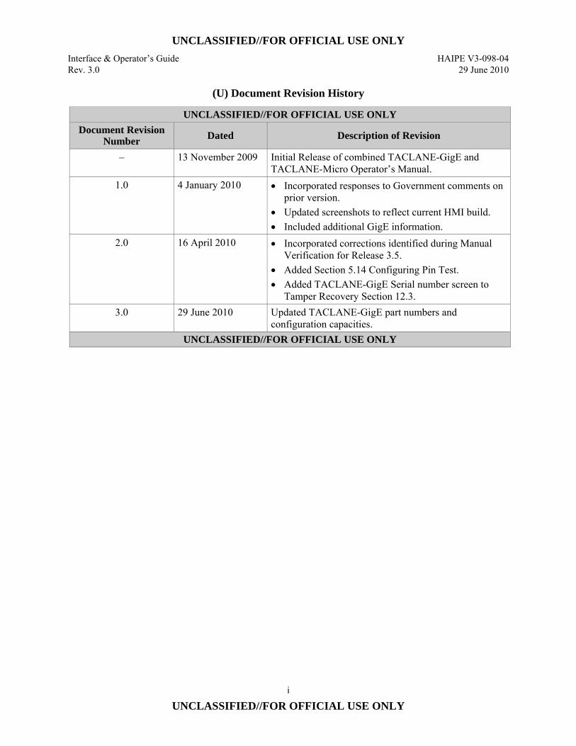
(U) Document Revision History
UNCLASSIFIED//FOR OFFICIAL USE ONLY Document Revision
Number Dated Description of Revision
– 13 November 2009 Initial Release of combined TACLANE-GigE and TACLANE-Micro Operator’s Manual.
1.0 4 January 2010 • Incorporated responses to Government comments on prior version.
• Updated screenshots to reflect current HMI build. • Included additional GigE information.
2.0 16 April 2010 • Incorporated corrections identified during Manual Verification for Release 3.5.
• Added Section 5.14 Configuring Pin Test. • Added TACLANE-GigE Serial number screen to
Tamper Recovery Section 12.3. 3.0 29 June 2010 Updated TACLANE-GigE part numbers and
configuration capacities. UNCLASSIFIED//FOR OFFICIAL USE ONLY

UNCLASSIFIED//FOR OFFICIAL USE ONLY
HAIPE V3-098-04 Interface & Operator’s Guide 29 June 2010 Rev. 3.0
ii
UNCLASSIFIED//FOR OFFICIAL USE ONLY
(U) This page intentionally left blank.
UNCLASSIFIED//FOR OFFICIAL USE ONLY Interface & Operator’s Guide HAIPE V3-098-04 Rev. 3.0 29 June2010
iii
UNCLASSIFIED//FOR OFFICIAL USE ONLY
(U) TABLE OF CONTENTS Section Page
1.0 (U) INTRODUCTION .................................................................................... 1-1 1.1 (U) About the Manual ....................................................................................... 1-1 1.2 (U) Referenced Documents ............................................................................... 1-3 1.3 (U) Acronyms and Abbreviations ..................................................................... 1-5 1.4 (U) Safety Information ...................................................................................... 1-13 1.5 (U) Hardware Versions ..................................................................................... 1-15 1.6 (U) Programmable Image Version .................................................................... 1-15 1.7 (U) Customer Support and Contacts ................................................................. 1-16
2.0 (U) ABOUT THE TACLANE ........................................................................ 2-1 2.1 (U) Introduction ................................................................................................. 2-1 2.2 (U) Concepts ..................................................................................................... 2-2 2.3 (U) Capabilities ................................................................................................. 2-9 2.4 (U) Web-based Human-Machine Interface (HMI) ............................................ 2-16
3.0 (U) INSTALLING AND OPERATING THE TACLANE ........................... 3-1 3.1 (U) Unpacking ................................................................................................... 3-1 3.2 (U) Equipment Checklist ................................................................................... 3-1 3.3 (U) Handling and Environmental Conditions.................................................... 3-4 3.4 (U) Mounting ..................................................................................................... 3-6 3.5 (U) Installing TACLANE Cables ...................................................................... 3-10 3.6 (U) Configuring the IP Network ....................................................................... 3-14 3.7 (U) Operating the TACLANE ........................................................................... 3-15 3.8 (U) Features ....................................................................................................... 3-22 3.9 (U) HMI Menu Tree .......................................................................................... 3-24
4.0 (U) FILLING, ISSUING AND MANAGING KEYS .................................... 4-1 4.1 (U) Obtaining DTDs, SKLs, and Keys .............................................................. 4-1 4.2 (U) Attaching a Fill Cable ................................................................................. 4-3 4.3 (U) Filling Keys (PPKs & FFVSs) from a DTD ............................................... 4-4 4.4 (U) Issuing Keys (PPKs & FFVSs) from a DTD .............................................. 4-5 4.5 (U) Displaying Issued Keys .............................................................................. 4-6 4.6 (U) Filling Issued Keys ..................................................................................... 4-8 4.7 (U) Deleting Issued Keys .................................................................................. 4-11 4.8 (U) Displaying Filled FIREFLY Vector Set Information ................................. 4-13 4.9 (U) Deleting a Filled FIREFLY Vector Set ...................................................... 4-15 4.10 (U) Displaying Unassigned Pre-Placed Key Information ................................. 4-16 4.11 (U) Deleting an Unassigned Pre-Placed Key .................................................... 4-18 4.12 (U) Displaying Pre-Placed Key Chains ............................................................. 4-19 4.13 (U) Creating a Pre-Placed Key Chain ............................................................... 4-21 4.14 (U) Assigning a Pre-Placed Key to an Existing Chain ...................................... 4-24 4.15 (U) Deleting a Pre-Placed Key Assigned to a Chain ......................................... 4-28 4.16 (U) Installing PAC ............................................................................................ 4-30 4.17 (U) Discarding PAC Available for Install ......................................................... 4-32 4.18 (U) Deleting Installed PAC ............................................................................... 4-34 4.19 (U) Displaying PAC Available for Install ......................................................... 4-36 4.20 (U) Displaying Installed PAC ........................................................................... 4-37 4.21 (U) Selecting a Security Level .......................................................................... 4-39
UNCLASSIFIED//FOR OFFICIAL USE ONLY HAIPE V3-098-04 Interface & Operator’s Guide 29 June 2010 Rev. 3.0
(U) TABLE OF CONTENTS (Cont.) Section Page
iv
UNCLASSIFIED//FOR OFFICIAL USE ONLY
4.22 (U) Exiting a Security Level ............................................................................. 4-40 4.23 (U) Configuring OOBKT TFTP Settings .......................................................... 4-42 4.24 (U) Displaying OOBKT NETCON Key Files ................................................... 4-43 4.25 (U) Creating an OOBKT NETCON Key File ................................................... 4-46 4.26 (U) Adding a Key to an OOBKT NETCON Key File ...................................... 4-49 4.27 (U) Deleting a Key from an OOBKT NETCON Key File ................................ 4-52 4.28 (U) Deleting an OOBKT NETCON Key File ................................................... 4-54 4.29 (U) Displaying OOBKT NETCON Client Transfers ........................................ 4-55 4.30 (U) Defining an OOBKT NETCON Client Transfer Entry .............................. 4-58 4.31 (U) Initiating an OOBKT NETCON Transfer to a Client ................................. 4-61 4.32 (U) Modifying an OOBKT NETCON Client Transfer Entry ............................ 4-63 4.33 (U) Deleting an OOBKT NETCON Client Transfer Entry ............................... 4-66 4.34 (U) Displaying OOBKT Client Authorized Controllers.................................... 4-68 4.35 (U) Adding an OOBKT Client Authorized Controller ...................................... 4-71 4.36 (U) Removing an OOBKT Client Authorized Controller ................................. 4-73 4.37 (U) Displaying IBKT NETCON Client Transfers ............................................. 4-75 4.38 (U) Defining an IBKT NETCON Client Transfer ............................................. 4-78 4.39 (U) Removing an IBKT NETCON Client Transfer .......................................... 4-82 4.40 (U) Displaying IBKT Client Authorized Controllers ........................................ 4-84 4.41 (U) Adding an IBKT Client Authorized Controller .......................................... 4-87 4.42 (U) Removing an IBKT Client Authorized Controller ...................................... 4-89 4.43 (U) Displaying IBKT Client PPKs Disabled for Supersession ......................... 4-91 4.44 (U) Disabling Supersession of an IBKT Client PPK ......................................... 4-94 4.45 (U) Reenabling Supersession of an IBKT Client PPK ...................................... 4-95
5.0 (U) CONFIGURING IP/ETHERNET ........................................................... 5-1 5.1 (U) Configuring the Ethernet Media and Physical Parameters ......................... 5-1 5.2 (U) Entering/Modifying the TACLANE IPv4 Network Configuration ............ 5-6 5.3 (U) Entering/Modifying the TACLANE IPv6 PT Interface Configuration ...... 5-10 5.4 (U) Entering/Modifying the TACLANE IPv6 PT Network Addresses ............ 5-14 5.5 (U) Entering/Modifying a TACLANE IPv6 CT Interface Configuration ......... 5-17 5.6 (U) Entering/Modifying a TACLANE IPv6 CT Network Address .................. 5-22 5.7 (U) Deleting a TACLANE IPv6 Network Address ........................................... 5-25 5.8 (U) Configuring Control Message MTU Values ............................................... 5-27 5.9 (U) Creating PT-to-CT Address Mapping for Multicast Control
Messages ........................................................................................................... 5-29 5.10 (U) Modifying PT-to-CT Address Mapping for Multicast Control
Messages ........................................................................................................... 5-31 5.11 (U) Deleting PT-to-CT Mapped Address Pair for Multicast Control
Messages ........................................................................................................... 5-34 5.12 (U) Displaying PT-to-CT Address Mapping for Multicast Control
Messages ........................................................................................................... 5-37 5.13 (U) Configuring Multicast Versions .................................................................. 5-39 5.14 (U) Configuring Ping Test ................................................................................. 5-40 5.15 (U) Configuring Ping Test, continued ............................................................. 5-41
UNCLASSIFIED//FOR OFFICIAL USE ONLY Interface & Operator’s Guide HAIPE V3-098-04 Rev. 3.0 29 June 2010
(U) TABLE OF CONTENTS (Cont.) Section Page
v
UNCLASSIFIED//FOR OFFICIAL USE ONLY
6.0 (U) CONFIGURING IP TRAFFIC FLOW SECURITY PARAMETERS ............................................................................................... 6-1
6.1 (U) Configuring Fixed Packet Length Parameters ............................................ 6-1 6.2 (U) Configuring IGMP Mode ............................................................................ 6-5 6.3 (U) Configuring MLD Mode ............................................................................. 6-7 6.4 (U) Displaying Traffic Flow Security Information ........................................... 6-9
7.0 (U) CONFIGURING ACCESS CONTROL AND THE NETWORK MANAGER ...................................................................................................... 7-1
7.1 (U) Enabling/Disabling Access Mode ............................................................... 7-1 7.2 (U) Creating an ACL Entry ............................................................................... 7-3 7.3 (U) Deleting an ACL Entry ............................................................................... 7-5 7.4 (U) Displaying ACL Entries .............................................................................. 7-6 7.5 (U) Adding a Network Manager ....................................................................... 7-7 7.6 (U) Editing a Network Manager’s Configuration ............................................. 7-12 7.7 (U) Deleting a Network Manager ...................................................................... 7-17 7.8 (U) Displaying Network Manager Information ................................................. 7-18
8.0 (U) CONFIGURING DISCOVERY .............................................................. 8-1 8.1 (U) Creating Delivery Servers ........................................................................... 8-1 8.2 (U) Modifying Delivery Servers ....................................................................... 8-3 8.3 (U) Deleting Delivery Servers ........................................................................... 8-4 8.4 (U) Configuring Discovery Messaging ............................................................. 8-6 8.5 (U) Creating Registration Servers ..................................................................... 8-7 8.6 (U) Displaying Registration Servers ................................................................. 8-9 8.7 (U) Deleting Registration Servers ..................................................................... 8-11 8.8 (U) Creating Solicitation Reception Addresses ................................................. 8-12 8.9 (U) Displaying Solicitation Reception Addresses ............................................. 8-14 8.10 (U) Deleting Solicitation Reception Addresses ................................................. 8-15
9.0 (U) SECURITY POLICY DATABASE (SPD) ............................................. 9-1 9.1 (U) Security Policy Database Overview............................................................ 9-1 9.2 (U) Steps to Securing Traffic with FIREFLY ................................................... 9-2 9.3 (U) Steps to Securing Traffic with PPK ............................................................ 9-3 9.4 (U) Creating FIREFLY SA Transforms ............................................................ 9-3 9.5 (U) Modifying FIREFLY SA Transforms ......................................................... 9-8 9.6 (U) Displaying FIREFLY SA Transforms ........................................................ 9-11 9.7 (U) Deleting FIREFLY SA Transforms ............................................................ 9-12 9.8 (U) Creating FIREFLY SA Templates .............................................................. 9-15 9.9 (U) Modifying FIREFLY SA Templates .......................................................... 9-23 9.10 (U) Displaying FIREFLY SA Templates .......................................................... 9-27 9.11 (U) Deleting FIREFLY SA Templates .............................................................. 9-29 9.12 (U) Creating Selectors ....................................................................................... 9-31 9.13 (U) Modifying Selectors .................................................................................... 9-37 9.14 (U) Displaying Selectors ................................................................................... 9-43 9.15 (U) Deleting Selectors ....................................................................................... 9-44 9.16 (U) Creating Rules ............................................................................................ 9-47 9.17 (U) Modifying Rules ......................................................................................... 9-51
UNCLASSIFIED//FOR OFFICIAL USE ONLY HAIPE V3-098-04 Interface & Operator’s Guide 29 June 2010 Rev. 3.0
(U) TABLE OF CONTENTS (Cont.) Section Page
vi
UNCLASSIFIED//FOR OFFICIAL USE ONLY
9.18 (U) Displaying Rules ......................................................................................... 9-54 9.19 (U) Deleting Rules ............................................................................................ 9-55
10.0 (U) CONFIGURING/MANAGING SECURITY ASSOCIATIONS .......... 10-1 10.1 (U) Entering Secure Communications State ...................................................... 10-1 10.2 (U) Exiting Secure Communications State........................................................ 10-4 10.3 (U) Displaying Security Association Info ......................................................... 10-5 10.4 (U) Deleting Security Association Info ............................................................. 10-7 10.5 (U) Configuring Router Advertisements ........................................................... 10-9 10.6 (U) Creating Remote TACLANE Routes .......................................................... 10-10 10.7 (U) Modifying Remote TACLANE Routes ...................................................... 10-16 10.8 (U) Deleting Remote TACLANE Routes .......................................................... 10-19 10.9 (U) Creating Local TACLANE Routes ............................................................. 10-22 10.10 (U) Modifying Local TACLANE Routes .......................................................... 10-26 10.11 (U) Deleting Local TACLANE Routes ............................................................. 10-28 10.12 (U) Enabling RIP Listener ................................................................................. 10-30 10.13 (U) Disabling RIP Listener ................................................................................ 10-32 10.14 (U) Enabling RIP Speaker ................................................................................. 10-33 10.15 (U) Disabling RIP Speaker ................................................................................ 10-35 10.16 (U) Creating PPK SAs ....................................................................................... 10-37 10.17 (U) Modifying PPK SAs ................................................................................... 10-45 10.18 (U) Displaying PPK SAs ................................................................................... 10-47 10.19 (U) Deleting PPK SAs ....................................................................................... 10-49
11.0 (U) MAINTAINING TACLANE ................................................................... 11-1 11.1 (U) Setting the Date and Time .......................................................................... 11-1 11.2 (U) Creating a CIK ............................................................................................ 11-2 11.3 (U) Deleting a CIK ............................................................................................ 11-7 11.4 (U) Displaying CIK Information ....................................................................... 11-8 11.5 (U) Restarting the TACLANE .......................................................................... 11-9 11.6 (U) Configuring/Displaying Battery Configuration .......................................... 11-10 11.7 (U) Configuring/Modifying Download Servers ................................................ 11-11 11.8 (U) Deleting Download Servers ........................................................................ 11-14 11.9 (U) Configuring Download TFTP Settings ....................................................... 11-15 11.10 (U) Downloading an FSU File .......................................................................... 11-16 11.11 (U) Installing a Software Image using FSU ...................................................... 11-20 11.12 (U) Installing Change Software Signature (CSC) Using FSU .......................... 11-24 11.13 (U) Displaying Software Signature ................................................................... 11-26 11.14 (U) Zeroizing the TACLANE ........................................................................... 11-27 11.15 (U) Configuring/Displaying System Information ............................................. 11-29 11.16 (U) Enabling SSO Privileges ............................................................................. 11-31 11.17 (U) Disabling SSO Privileges ............................................................................ 11-34 11.18 (U) Generating SSO PIN ................................................................................... 11-35 11.19 (U) Configuring Audit Log Threshold .............................................................. 11-37 11.20 (U) Deleting the Audit Log ............................................................................... 11-38 11.21 (U) Displaying the Audit Log ........................................................................... 11-39 11.22 (U) Displaying the Event Log ........................................................................... 11-40 11.23 (U) Resetting Configuration .............................................................................. 11-41
UNCLASSIFIED//FOR OFFICIAL USE ONLY Interface & Operator’s Guide HAIPE V3-098-04 Rev. 3.0 29 June 2010
(U) TABLE OF CONTENTS (Cont.) Section Page
vii
UNCLASSIFIED//FOR OFFICIAL USE ONLY
11.24 (U) Sanitizing the TACLANE ........................................................................... 11-42
12.0 (U) TROUBLESHOOTING TACLANE ....................................................... 12-1 12.1 (U) Alarm .......................................................................................................... 12-1 12.2 (U) Tamper ........................................................................................................ 12-1 12.3 (U) Performing a Field Tamper Recovery ......................................................... 12-2 12.4 (U) Checking for a Low Battery ........................................................................ 12-6 12.5 (U) Replacing the Battery .................................................................................. 12-6 12.6 (U) Performing Diagnostics .............................................................................. 12-8 12.7 (U) Troubleshooting General Problems ............................................................ 12-9 12.8 (U) Troubleshooting Filling and Managing Keys ............................................. 12-9 12.9 (U) Troubleshooting IP/Ethernet ....................................................................... 12-10 12.10 (U) Troubleshooting Security Associations ...................................................... 12-11
APPENDIX A (U) FACTORY DEFAULT SETTINGS ........................................................ A-1
APPENDIX B (U) IP/ETHERNET CONFIGURATION TIPS ........................................... B-1
APPENDIX C (U) STATUS MESSAGES .............................................................................. C-1
APPENDIX D (U) SETTING UP A NETWORK .................................................................. D-1
APPENDIX E (U) MIB OBJECTS USED IN HMI SCREENS ........................................... E-1
APPENDIX F (U) GDC BACKGROUND AND TIPS .......................................................... F-1
APPENDIX G (U) IM-PEPD BACKGROUND AND TIPS .................................................. G-1

UNCLASSIFIED//FOR OFFICIAL USE ONLY HAIPE V3-098-04 Interface & Operator’s Guide 29 June 2010 Rev. 3.0
viii
UNCLASSIFIED//FOR OFFICIAL USE ONLY
(U) This page intentionally left blank.
UNCLASSIFIED//FOR OFFICIAL USE ONLY Interface & Operator’s Guide HAIPE V3-098-04 Rev. 3.0 29 June 2010
ix
UNCLASSIFIED//FOR OFFICIAL USE ONLY
(U) LIST OF FIGURES Figure Page Figure 3.4-1 (U) TACLANE-Micro Mounting Information ............................................................. 3-8 Figure 3.5-1 (U) TACLANE-Micro Rear Panel ............................................................................... 3-10 Figure 3.5-2 (U) TACLANE-GigE Rear Panel................................................................................. 3-10 Figure 3.6-1 (U) TACLANE-Secured IP/Ethernet Network ............................................................ 3-14 Figure 3.7-1 (U) TACLANE-Micro Front Panel .............................................................................. 3-15 Figure 3.7-2 (U) TACLANE-GigE Front Panel ............................................................................... 3-15 Figure 9.1-1 (U) Security Policy Database Relationships ................................................................ 9-1 Figure B.2-1 (U) TACLANE-Secured IP/Ethernet Network ............................................................ B-1 Figure B.4-1 (U) TACLANE Configuration ..................................................................................... B-8 Figure B.4-2 (U) TACLANE Configuration With IP Tunnels ......................................................... B-9 Figure B.5-1 (U) TACLANE Encryption Gateway Connecting Two Networks .............................. B-10 Figure B.5-2 (U) TACLANE Encryption Gateway Connecting Many Subnet Enclaves ................. B-11 Figure B.6-1 (U) TACLANE Multiple Gateway Configuration Example ........................................ B-14 Figure B.6-2 (U) TACLANE Single Gateway Nested Configuration Example ............................... B-15 Figure B.7-1 (U) Multiple CT Default Gateways ............................................................................. B-17 Figure B.7-2 (U) False Subnet Mask Configuration ......................................................................... B-19 Figure B.7-3 (U) Added Router Configuration ................................................................................. B-20 Figure B.7-4 (U) Manual PPK Configuration ................................................................................... B-21 Figure B.8-1 (U) Single-Ended TACLANE Redundancy with Router Redundancy ....................... B-23 Figure B.8-2 (U) Single-Ended TACLANE Redundancy without Router Redundancy .................. B-25 Figure B.8-3 (U) Using Four GRE Tunnels to Provide Double-Ended TACLANE
Redundancy without Router Redundancy ................................................................................ B-27 Figure D.1-1 (U) TACLANE-Secured IPv4 Network ...................................................................... D-1 Figure D.1-2 (U) TACLANE-Secured IPv6 Network ...................................................................... D-1 Figure F.2-1 (U) Generic Discovery Based Network ....................................................................... F-2 Figure G.2-1 (U) TACLANE Network using IM-PEPD Basic Discovery ....................................... G-2 Figure G.2-2 (U) TACLANE Network using IM-PEPD Segmented Core Discovery ..................... G-3 Figure G.2-3 (U) TACLANE Network using IM-PEPD Segmented Core Discovery, Multiple
PT Networks ............................................................................................................................ G-4

UNCLASSIFIED//FOR OFFICIAL USE ONLY HAIPE V3-098-04 Interface & Operator’s Guide 29 June 2010 Rev. 3.0
x
UNCLASSIFIED//FOR OFFICIAL USE ONLY
(U) This page intentionally left blank
UNCLASSIFIED//FOR OFFICIAL USE ONLY Interface & Operator’s Guide HAIPE V3-098-04 Rev. 3.0 29 June 2010
1-1
UNCLASSIFIED//FOR OFFICIAL USE ONLY
1.0 (U) INTRODUCTION
1.1 (U) About the Manual
Purpose (U//FOUO) The purpose of this manual is to explain how to install, operate, and
reconfigure the General Dynamics TACLANE™1 Micro and GigE encryptors.
Audience (U//FOUO) This manual is intended for operators with a basic understanding of IP
networking, as well as data encryption.
Edition (U//FOUO) This is the Operator’s Manual for the TACLANE in-line encryptor
(INE) products. It includes information specific to TACLANEs that are High Assurance Internet Protocol Interoperability Specification (HAIPE™2 IS) v3.1.2 compliant.
Changes (U//FOUO) The information presented in this manual is subject to change without
notice. Any changes will be incorporated in subsequent editions, or change pages will be issued.
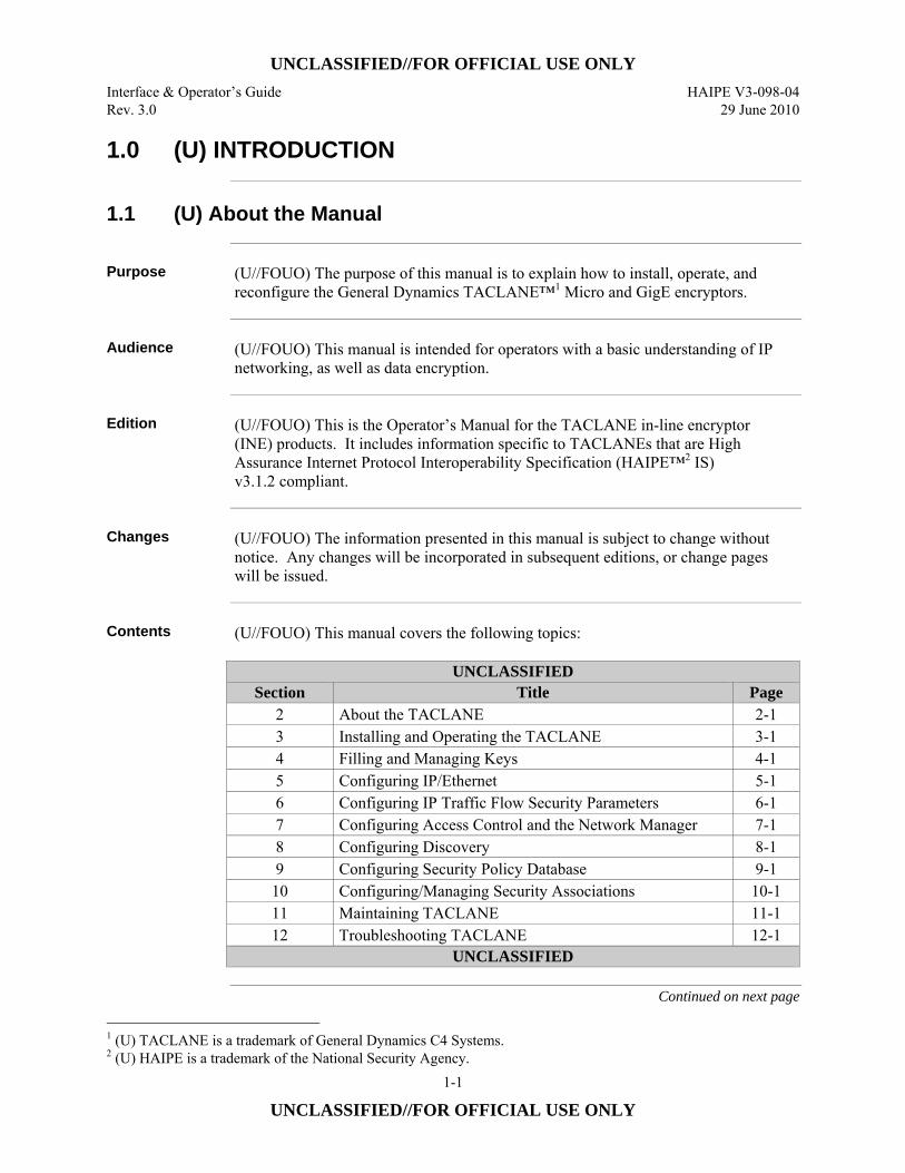
Contents (U//FOUO) This manual covers the following topics:
UNCLASSIFIED Section Title Page
2 About the TACLANE 2-1 3 Installing and Operating the TACLANE 3-1 4 Filling and Managing Keys 4-1 5 Configuring IP/Ethernet 5-1 6 Configuring IP Traffic Flow Security Parameters 6-1 7 Configuring Access Control and the Network Manager 7-1 8 Configuring Discovery 8-1 9 Configuring Security Policy Database 9-1 10 Configuring/Managing Security Associations 10-1 11 Maintaining TACLANE 11-1 12 Troubleshooting TACLANE 12-1
UNCLASSIFIED
Continued on next page
1 (U) TACLANE is a trademark of General Dynamics C4 Systems. 2 (U) HAIPE is a trademark of the National Security Agency.
UNCLASSIFIED//FOR OFFICIAL USE ONLY HAIPE V3-098-04 Interface & Operator’s Guide 29 June 2010 Rev. 3.0
1-2
UNCLASSIFIED//FOR OFFICIAL USE ONLY
1.1 (U) About the Manual, continued
Contents (Cont.)
UNCLASSIFIED Section Title Page
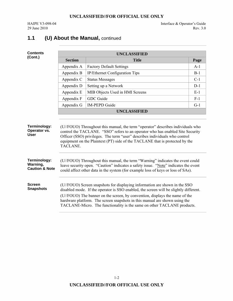
Appendix A Factory Default Settings A-1 Appendix B IP/Ethernet Configuration Tips B-1 Appendix C Status Messages C-1 Appendix D Setting up a Network D-1 Appendix E MIB Objects Used in HMI Screens E-1 Appendix F GDC Guide F-1 Appendix G IM-PEPD Guide G-1
UNCLASSIFIED
Terminology: Operator vs. User
(U//FOUO) Throughout this manual, the term “operator” describes individuals who control the TACLANE. “SSO” refers to an operator who has enabled Site Security Officer (SSO) privileges. The term “user” describes individuals who control equipment on the Plaintext (PT) side of the TACLANE that is protected by the TACLANE.
Terminology: Warning, Caution & Note
(U//FOUO) Throughout this manual, the term “Warning” indicates the event could leave security open. “Caution” indicates a safety issue. “Note” indicates the event could affect other data in the system (for example loss of keys or loss of SAs).
Screen Snapshots
(U//FOUO) Screen snapshots for displaying information are shown in the SSO disabled mode. If the operator is SSO enabled, the screen will be slightly different. (U//FOUO) The banner on the screen, by convention, displays the name of the hardware platform. The screen snapshots in this manual are shown using the TACLANE-Micro. The functionality is the same on other TACLANE products.
UNCLASSIFIED//FOR OFFICIAL USE ONLY Interface & Operator’s Guide HAIPE V3-098-04 Rev. 3.0 29 June 2010
1-3
UNCLASSIFIED//FOR OFFICIAL USE ONLY
1.2 (U) Referenced Documents
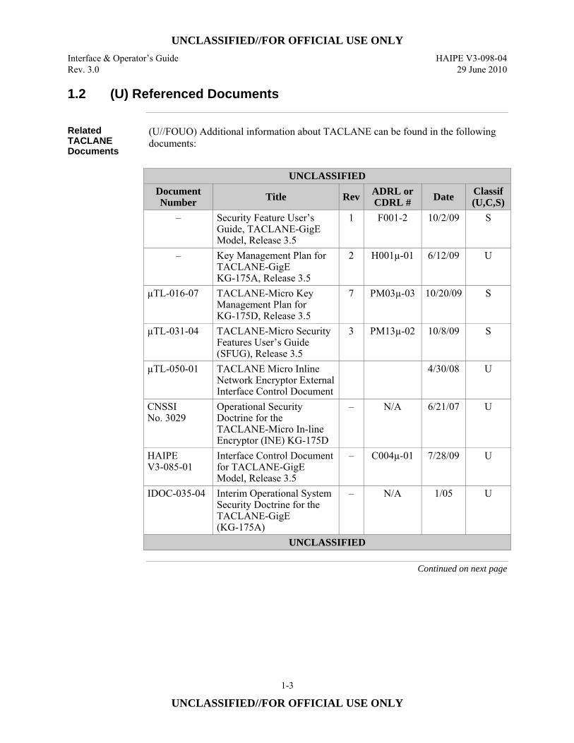
Related TACLANE Documents
(U//FOUO) Additional information about TACLANE can be found in the following documents:
UNCLASSIFIED
Document Number Title Rev ADRL or
CDRL # Date Classif (U,C,S)
– Security Feature User’s Guide, TACLANE-GigE Model, Release 3.5
1 F001-2 10/2/09 S
– Key Management Plan for TACLANE-GigE KG-175A, Release 3.5
2 H001µ-01 6/12/09 U
µTL-016-07 TACLANE-Micro Key Management Plan for KG-175D, Release 3.5
7 PM03µ-03 10/20/09 S
µTL-031-04 TACLANE-Micro Security Features User’s Guide (SFUG), Release 3.5
3 PM13µ-02 10/8/09 S
µTL-050-01 TACLANE Micro Inline Network Encryptor External Interface Control Document
4/30/08 U
CNSSI No. 3029
Operational Security Doctrine for the TACLANE-Micro In-line Encryptor (INE) KG-175D
– N/A 6/21/07 U
HAIPE V3-085-01
Interface Control Document for TACLANE-GigE Model, Release 3.5
– C004µ-01 7/28/09 U
IDOC-035-04 Interim Operational System Security Doctrine for the TACLANE-GigE (KG-175A)
– N/A 1/05 U
UNCLASSIFIED
Continued on next page
UNCLASSIFIED//FOR OFFICIAL USE ONLY HAIPE V3-098-04 Interface & Operator’s Guide 29 June 2010 Rev. 3.0
1-4
UNCLASSIFIED//FOR OFFICIAL USE ONLY
1.2 (U) Referenced Documents, continued
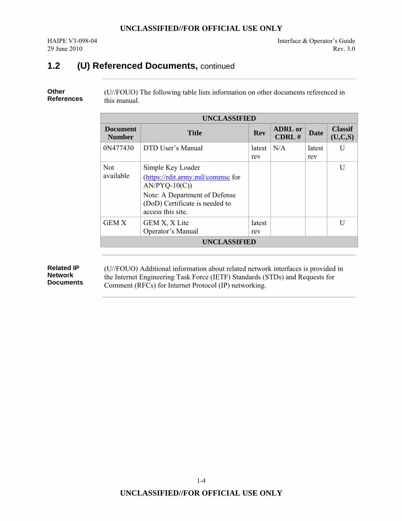
Other References
(U//FOUO) The following table lists information on other documents referenced in this manual.
UNCLASSIFIED
Document Number Title Rev ADRL or
CDRL # Date Classif (U,C,S)
0N477430 DTD User’s Manual latest rev
N/A latest rev
U
Not available
Simple Key Loader (https://rdit.army.mil/commsc for AN/PYQ-10(C)) Note: A Department of Defense (DoD) Certificate is needed to access this site.
U
GEM X GEM X, X Lite Operator’s Manual
latest rev
U
UNCLASSIFIED
Related IP Network Documents
(U//FOUO) Additional information about related network interfaces is provided in the Internet Engineering Task Force (IETF) Standards (STDs) and Requests for Comment (RFCs) for Internet Protocol (IP) networking.
UNCLASSIFIED//FOR OFFICIAL USE ONLY Interface & Operator’s Guide HAIPE V3-098-04 Rev. 3.0 29 June 2010
1-5
UNCLASSIFIED//FOR OFFICIAL USE ONLY
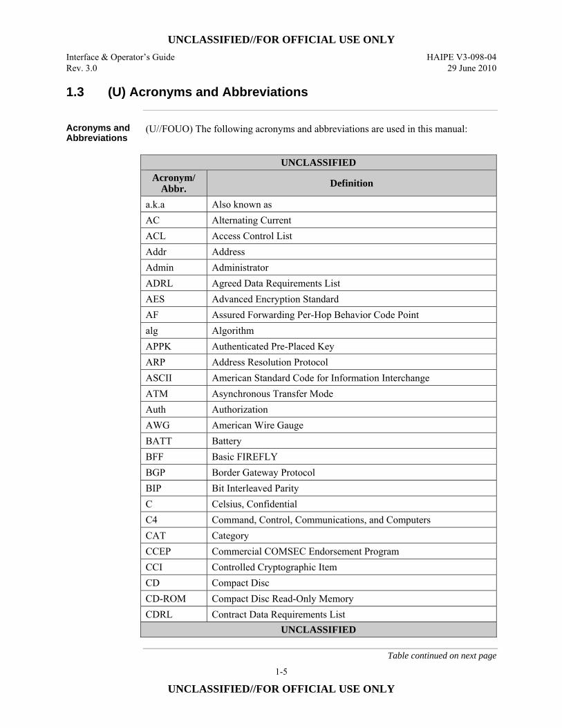
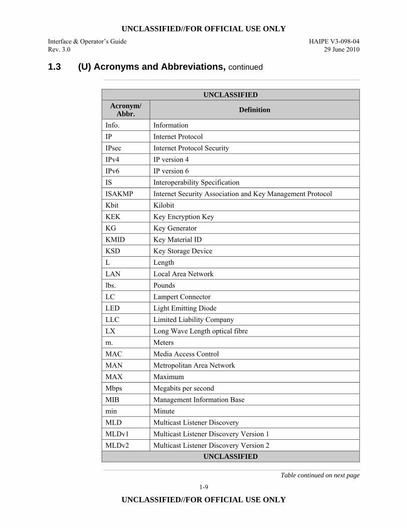
1.3 (U) Acronyms and Abbreviations
Acronyms and Abbreviations
(U//FOUO) The following acronyms and abbreviations are used in this manual:
UNCLASSIFIED
Acronym/ Abbr. Definition
a.k.a Also known as AC Alternating Current ACL Access Control List Addr Address Admin Administrator ADRL Agreed Data Requirements List AES Advanced Encryption Standard AF Assured Forwarding Per-Hop Behavior Code Point alg Algorithm APPK Authenticated Pre-Placed Key ARP Address Resolution Protocol ASCII American Standard Code for Information Interchange ATM Asynchronous Transfer Mode Auth Authorization AWG American Wire Gauge BATT Battery BFF Basic FIREFLY BGP Border Gateway Protocol BIP Bit Interleaved Parity C Celsius, Confidential C4 Command, Control, Communications, and Computers CAT Category CCEP Commercial COMSEC Endorsement Program CCI Controlled Cryptographic Item CD Compact Disc CD-ROM Compact Disc Read-Only Memory CDRL Contract Data Requirements List
UNCLASSIFIED
Table continued on next page
UNCLASSIFIED//FOR OFFICIAL USE ONLY HAIPE V3-098-04 Interface & Operator’s Guide 29 June 2010 Rev. 3.0
1-6
UNCLASSIFIED//FOR OFFICIAL USE ONLY
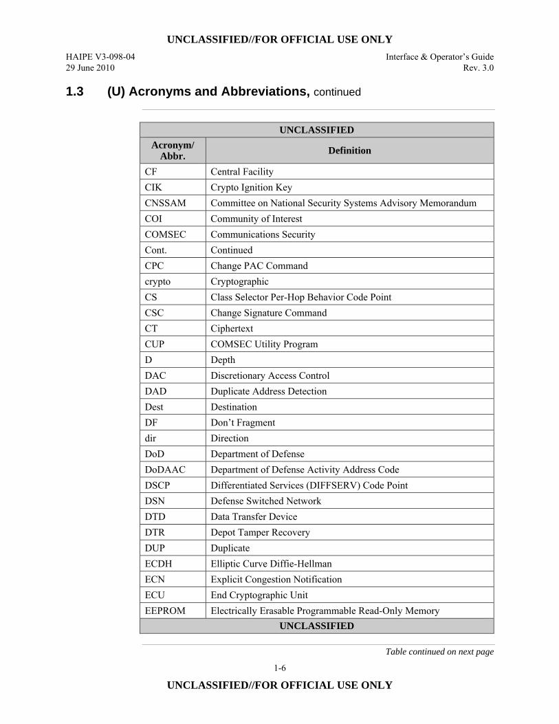
1.3 (U) Acronyms and Abbreviations, continued
UNCLASSIFIED
Acronym/ Abbr. Definition
CF Central Facility CIK Crypto Ignition Key CNSSAM Committee on National Security Systems Advisory Memorandum COI Community of Interest COMSEC Communications Security Cont. Continued CPC Change PAC Command crypto Cryptographic CS Class Selector Per-Hop Behavior Code Point CSC Change Signature Command CT Ciphertext CUP COMSEC Utility Program D Depth DAC Discretionary Access Control DAD Duplicate Address Detection Dest Destination DF Don’t Fragment dir Direction DoD Department of Defense DoDAAC Department of Defense Activity Address Code DSCP Differentiated Services (DIFFSERV) Code Point DSN Defense Switched Network DTD Data Transfer Device DTR Depot Tamper Recovery DUP Duplicate ECDH Elliptic Curve Diffie-Hellman ECN Explicit Congestion Notification ECU End Cryptographic Unit EEPROM Electrically Erasable Programmable Read-Only Memory
UNCLASSIFIED
Table continued on next page
UNCLASSIFIED//FOR OFFICIAL USE ONLY Interface & Operator’s Guide HAIPE V3-098-04 Rev. 3.0 29 June 2010
1-7
UNCLASSIFIED//FOR OFFICIAL USE ONLY
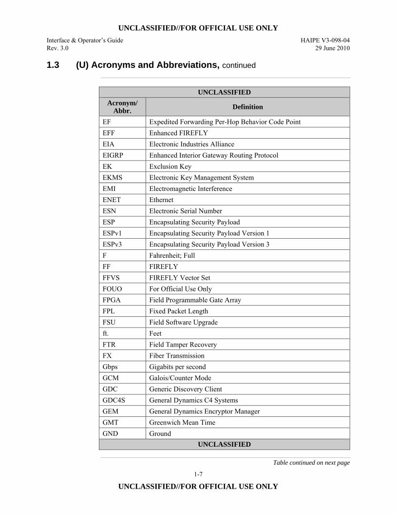
1.3 (U) Acronyms and Abbreviations, continued
UNCLASSIFIED
Acronym/ Abbr. Definition
EF Expedited Forwarding Per-Hop Behavior Code Point EFF Enhanced FIREFLY EIA Electronic Industries Alliance EIGRP Enhanced Interior Gateway Routing Protocol EK Exclusion Key EKMS Electronic Key Management System EMI Electromagnetic Interference ENET Ethernet ESN Electronic Serial Number ESP Encapsulating Security Payload ESPv1 Encapsulating Security Payload Version 1 ESPv3 Encapsulating Security Payload Version 3 F Fahrenheit; Full FF FIREFLY FFVS FIREFLY Vector Set FOUO For Official Use Only FPGA Field Programmable Gate Array FPL Fixed Packet Length FSU Field Software Upgrade ft. Feet FTR Field Tamper Recovery FX Fiber Transmission Gbps Gigabits per second GCM Galois/Counter Mode GDC Generic Discovery Client GDC4S General Dynamics C4 Systems GEM General Dynamics Encryptor Manager GMT Greenwich Mean Time GND Ground
UNCLASSIFIED
Table continued on next page
UNCLASSIFIED//FOR OFFICIAL USE ONLY HAIPE V3-098-04 Interface & Operator’s Guide 29 June 2010 Rev. 3.0
1-8
UNCLASSIFIED//FOR OFFICIAL USE ONLY
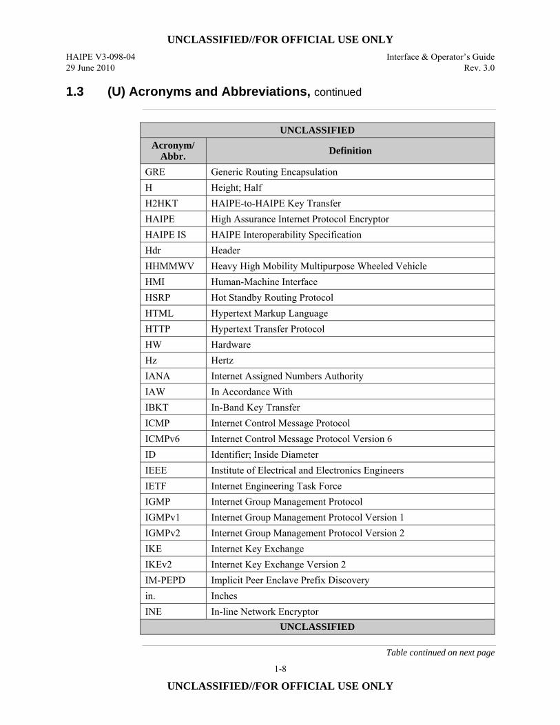
1.3 (U) Acronyms and Abbreviations, continued
UNCLASSIFIED
Acronym/ Abbr. Definition
GRE Generic Routing Encapsulation H Height; Half H2HKT HAIPE-to-HAIPE Key Transfer HAIPE High Assurance Internet Protocol Encryptor HAIPE IS HAIPE Interoperability Specification Hdr Header HHMMWV Heavy High Mobility Multipurpose Wheeled Vehicle HMI Human-Machine Interface HSRP Hot Standby Routing Protocol HTML Hypertext Markup Language HTTP Hypertext Transfer Protocol HW Hardware Hz Hertz IANA Internet Assigned Numbers Authority IAW In Accordance With IBKT In-Band Key Transfer ICMP Internet Control Message Protocol ICMPv6 Internet Control Message Protocol Version 6 ID Identifier; Inside Diameter IEEE Institute of Electrical and Electronics Engineers IETF Internet Engineering Task Force IGMP Internet Group Management Protocol IGMPv1 Internet Group Management Protocol Version 1 IGMPv2 Internet Group Management Protocol Version 2 IKE Internet Key Exchange IKEv2 Internet Key Exchange Version 2 IM-PEPD Implicit Peer Enclave Prefix Discovery in. Inches INE In-line Network Encryptor
UNCLASSIFIED
Table continued on next page
UNCLASSIFIED//FOR OFFICIAL USE ONLY Interface & Operator’s Guide HAIPE V3-098-04 Rev. 3.0 29 June 2010
1-9
UNCLASSIFIED//FOR OFFICIAL USE ONLY
1.3 (U) Acronyms and Abbreviations, continued
UNCLASSIFIED
Acronym/ Abbr. Definition
Info. Information IP Internet Protocol IPsec Internet Protocol Security IPv4 IP version 4 IPv6 IP version 6 IS Interoperability Specification ISAKMP Internet Security Association and Key Management Protocol Kbit Kilobit KEK Key Encryption Key KG Key Generator KMID Key Material ID KSD Key Storage Device L Length LAN Local Area Network lbs. Pounds LC Lampert Connector LED Light Emitting Diode LLC Limited Liability Company LX Long Wave Length optical fibre m. Meters MAC Media Access Control MAN Metropolitan Area Network MAX Maximum Mbps Megabits per second MIB Management Information Base min Minute MLD Multicast Listener Discovery MLDv1 Multicast Listener Discovery Version 1 MLDv2 Multicast Listener Discovery Version 2
UNCLASSIFIED
Table continued on next page
UNCLASSIFIED//FOR OFFICIAL USE ONLY HAIPE V3-098-04 Interface & Operator’s Guide 29 June 2010 Rev. 3.0
1-10
UNCLASSIFIED//FOR OFFICIAL USE ONLY
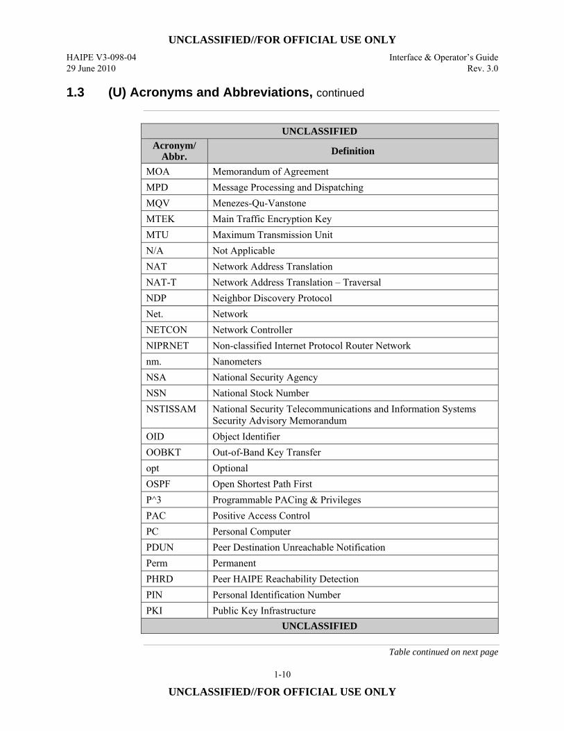
1.3 (U) Acronyms and Abbreviations, continued
UNCLASSIFIED
Acronym/ Abbr. Definition
MOA Memorandum of Agreement MPD Message Processing and Dispatching MQV Menezes-Qu-Vanstone MTEK Main Traffic Encryption Key MTU Maximum Transmission Unit N/A Not Applicable NAT Network Address Translation NAT-T Network Address Translation – Traversal NDP Neighbor Discovery Protocol Net. Network NETCON Network Controller NIPRNET Non-classified Internet Protocol Router Network nm. Nanometers NSA National Security Agency NSN National Stock Number NSTISSAM National Security Telecommunications and Information Systems
Security Advisory Memorandum OID Object Identifier OOBKT Out-of-Band Key Transfer opt Optional OSPF Open Shortest Path First P^3 Programmable PACing & Privileges PAC Positive Access Control PC Personal Computer PDUN Peer Destination Unreachable Notification Perm Permanent PHRD Peer HAIPE Reachability Detection PIN Personal Identification Number PKI Public Key Infrastructure
UNCLASSIFIED
Table continued on next page
UNCLASSIFIED//FOR OFFICIAL USE ONLY Interface & Operator’s Guide HAIPE V3-098-04 Rev. 3.0 29 June 2010
1-11
UNCLASSIFIED//FOR OFFICIAL USE ONLY
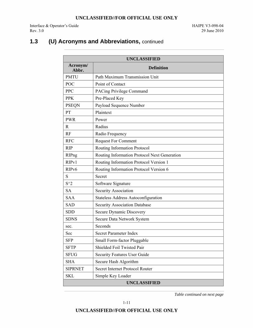
1.3 (U) Acronyms and Abbreviations, continued
UNCLASSIFIED
Acronym/ Abbr. Definition
PMTU Path Maximum Transmission Unit POC Point of Contact PPC PACing Privilege Command PPK Pre-Placed Key PSEQN Payload Sequence Number PT Plaintext PWR Power R Radius RF Radio Frequency RFC Request For Comment RIP Routing Information Protocol RIPng Routing Information Protocol Next Generation RIPv1 Routing Information Protocol Version 1 RIPv6 Routing Information Protocol Version 6 S Secret S^2 Software Signature SA Security Association SAA Stateless Address Autoconfiguration SAD Security Association Database SDD Secure Dynamic Discovery SDNS Secure Data Network System sec. Seconds Sec Secret Parameter Index SFP Small Form-factor Pluggable SFTP Shielded Foil Twisted Pair SFUG Security Features User Guide SHA Secure Hash Algorithm SIPRNET Secret Internet Protocol Router SKL Simple Key Loader
UNCLASSIFIED
Table continued on next page
UNCLASSIFIED//FOR OFFICIAL USE ONLY HAIPE V3-098-04 Interface & Operator’s Guide 29 June 2010 Rev. 3.0
1-12
UNCLASSIFIED//FOR OFFICIAL USE ONLY
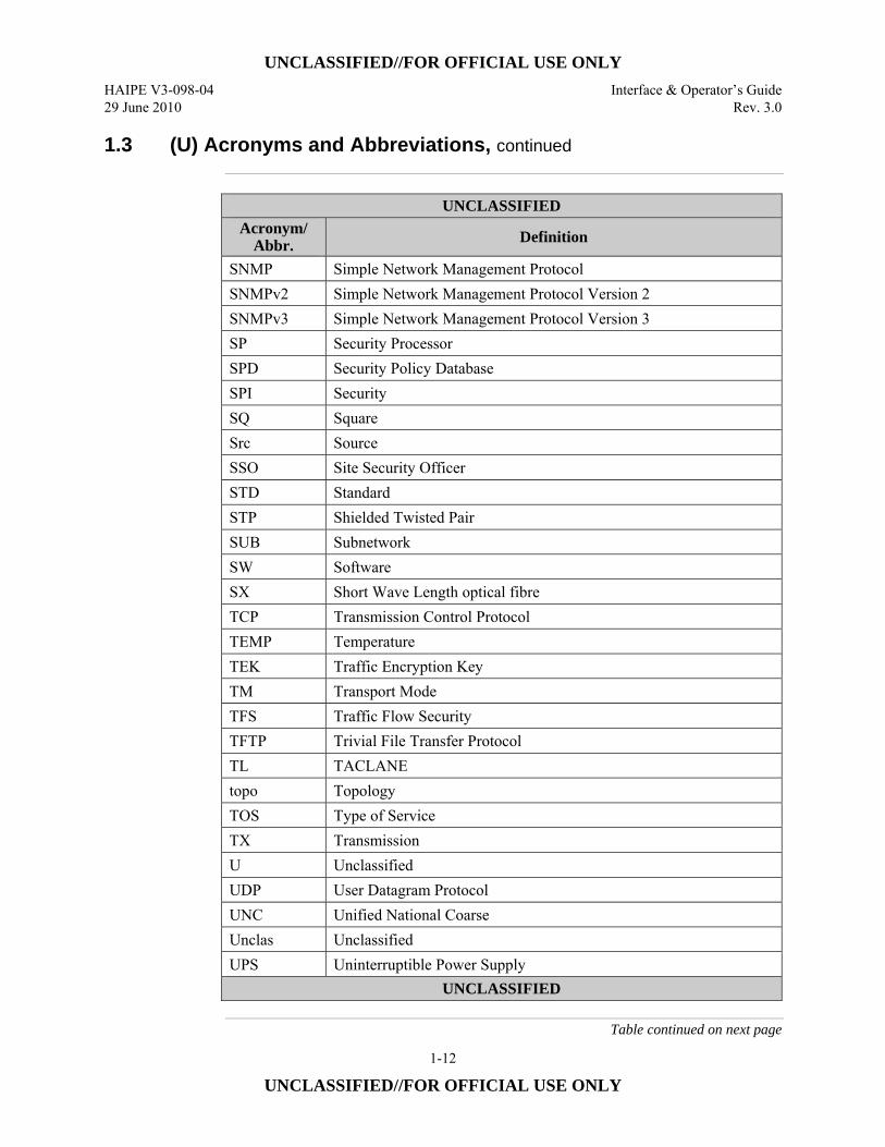
1.3 (U) Acronyms and Abbreviations, continued
UNCLASSIFIED
Acronym/ Abbr. Definition
SNMP Simple Network Management Protocol SNMPv2 Simple Network Management Protocol Version 2 SNMPv3 Simple Network Management Protocol Version 3 SP Security Processor SPD Security Policy Database SPI Security SQ Square Src Source SSO Site Security Officer STD Standard STP Shielded Twisted Pair SUB Subnetwork SW Software SX Short Wave Length optical fibre TCP Transmission Control Protocol TEMP Temperature TEK Traffic Encryption Key TM Transport Mode TFS Traffic Flow Security TFTP Trivial File Transfer Protocol TL TACLANE topo Topology TOS Type of Service TX Transmission U Unclassified UDP User Datagram Protocol UNC Unified National Coarse Unclas Unclassified UPS Uninterruptible Power Supply
UNCLASSIFIED
Table continued on next page
UNCLASSIFIED//FOR OFFICIAL USE ONLY Interface & Operator’s Guide HAIPE V3-098-04 Rev. 3.0 29 June 2010
1-13
UNCLASSIFIED//FOR OFFICIAL USE ONLY
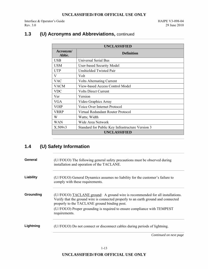
1.3 (U) Acronyms and Abbreviations, continued
UNCLASSIFIED Acronym/
Abbr. Definition
USB Universal Serial Bus USM User-based Security Model UTP Unshielded Twisted Pair V Volt VAC Volts Alternating Current VACM View-based Access Control Model VDC Volts Direct Current Ver Version VGA Video Graphics Array VOIP Voice Over Internet Protocol VRRP Virtual Redundant Router Protocol W Watts; Width WAN Wide Area Network X.509v3 Standard for Public Key Infrastructure Version 3
UNCLASSIFIED
1.4 (U) Safety Information
General (U//FOUO) The following general safety precautions must be observed during
installation and operation of the TACLANE.
Liability (U//FOUO) General Dynamics assumes no liability for the customer’s failure to
comply with these requirements.
Grounding (U//FOUO) TACLANE ground: A ground wire is recommended for all installations.
Verify that the ground wire is connected properly to an earth ground and connected properly to the TACLANE ground binding post. (U//FOUO) Proper grounding is required to ensure compliance with TEMPEST requirements.
Lightning (U//FOUO) Do not connect or disconnect cables during periods of lightning.
Continued on next page
UNCLASSIFIED//FOR OFFICIAL USE ONLY HAIPE V3-098-04 Interface & Operator’s Guide 29 June 2010 Rev. 3.0
1-14
UNCLASSIFIED//FOR OFFICIAL USE ONLY
1.4 (U) Safety Information, continued
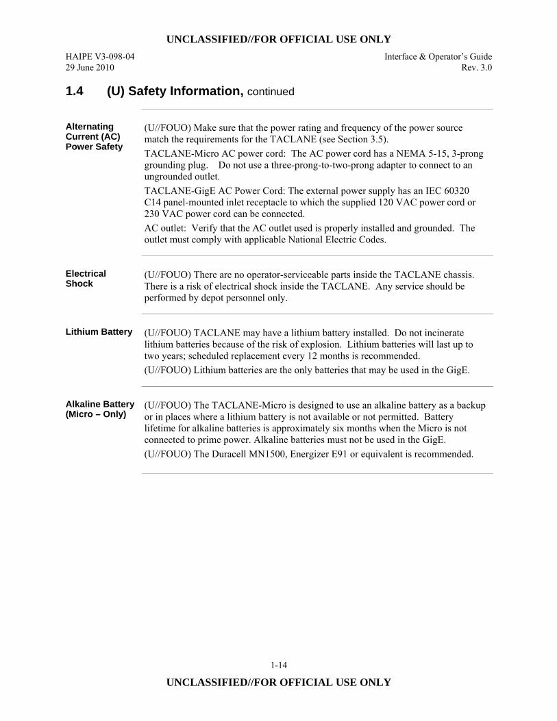
Alternating Current (AC) Power Safety
(U//FOUO) Make sure that the power rating and frequency of the power source match the requirements for the TACLANE (see Section 3.5). TACLANE-Micro AC power cord: The AC power cord has a NEMA 5-15, 3-prong grounding plug. Do not use a three-prong-to-two-prong adapter to connect to an ungrounded outlet. TACLANE-GigE AC Power Cord: The external power supply has an IEC 60320 C14 panel-mounted inlet receptacle to which the supplied 120 VAC power cord or 230 VAC power cord can be connected. AC outlet: Verify that the AC outlet used is properly installed and grounded. The outlet must comply with applicable National Electric Codes.
Electrical Shock
(U//FOUO) There are no operator-serviceable parts inside the TACLANE chassis. There is a risk of electrical shock inside the TACLANE. Any service should be performed by depot personnel only.
Lithium Battery (U//FOUO) TACLANE may have a lithium battery installed. Do not incinerate
lithium batteries because of the risk of explosion. Lithium batteries will last up to two years; scheduled replacement every 12 months is recommended. (U//FOUO) Lithium batteries are the only batteries that may be used in the GigE.
Alkaline Battery (Micro – Only)
(U//FOUO) The TACLANE-Micro is designed to use an alkaline battery as a backup or in places where a lithium battery is not available or not permitted. Battery lifetime for alkaline batteries is approximately six months when the Micro is not connected to prime power. Alkaline batteries must not be used in the GigE. (U//FOUO) The Duracell MN1500, Energizer E91 or equivalent is recommended.
UNCLASSIFIED//FOR OFFICIAL USE ONLY Interface & Operator’s Guide HAIPE V3-098-04 Rev. 3.0 29 June 2010
1-15
UNCLASSIFIED//FOR OFFICIAL USE ONLY
1.5 (U) Hardware Versions
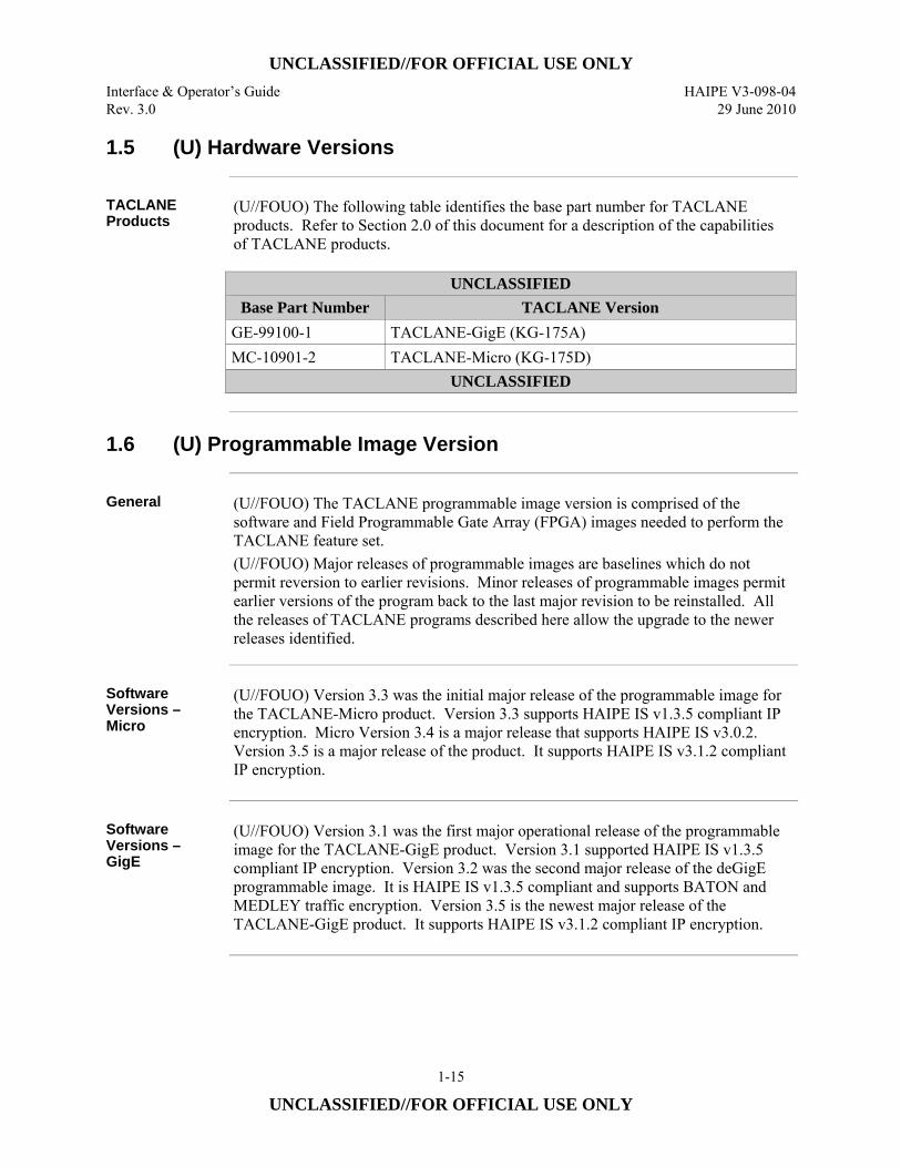
TACLANE Products
(U//FOUO) The following table identifies the base part number for TACLANE products. Refer to Section 2.0 of this document for a description of the capabilities of TACLANE products.
UNCLASSIFIED
Base Part Number TACLANE Version GE-99100-1 TACLANE-GigE (KG-175A) MC-10901-2 TACLANE-Micro (KG-175D)
UNCLASSIFIED
1.6 (U) Programmable Image Version
General (U//FOUO) The TACLANE programmable image version is comprised of the
software and Field Programmable Gate Array (FPGA) images needed to perform the TACLANE feature set. (U//FOUO) Major releases of programmable images are baselines which do not permit reversion to earlier revisions. Minor releases of programmable images permit earlier versions of the program back to the last major revision to be reinstalled. All the releases of TACLANE programs described here allow the upgrade to the newer releases identified.
Software Versions – Micro
(U//FOUO) Version 3.3 was the initial major release of the programmable image for the TACLANE-Micro product. Version 3.3 supports HAIPE IS v1.3.5 compliant IP encryption. Micro Version 3.4 is a major release that supports HAIPE IS v3.0.2. Version 3.5 is a major release of the product. It supports HAIPE IS v3.1.2 compliant IP encryption.
Software Versions – GigE
(U//FOUO) Version 3.1 was the first major operational release of the programmable image for the TACLANE-GigE product. Version 3.1 supported HAIPE IS v1.3.5 compliant IP encryption. Version 3.2 was the second major release of the deGigE programmable image. It is HAIPE IS v1.3.5 compliant and supports BATON and MEDLEY traffic encryption. Version 3.5 is the newest major release of the TACLANE-GigE product. It supports HAIPE IS v3.1.2 compliant IP encryption.
UNCLASSIFIED//FOR OFFICIAL USE ONLY HAIPE V3-098-04 Interface & Operator’s Guide 29 June 2010 Rev. 3.0
1-16
UNCLASSIFIED//FOR OFFICIAL USE ONLY
1.7 (U) Customer Support and Contacts
TACLANE Help Desk
(U//FOUO) For technical support and installation questions, please contact the General Dynamics C4 Systems Help Desk at: Phone: (877) 230-0236 E-mail: [email protected]
TACLANE Product Registration
(U//FOUO) TACLANE product registration is recommended. Contact the TACLANE Help Desk to register a TACLANE unit. Registration information includes: • TACLANE unit serial number • Operational location • User Representative Point of Contact (POC).
TACLANE Sales Support
(U//FOUO) For TACLANE sales support inquiries, please contact the TACLANE Sales Support group at:
General Dynamics - C4 Systems Attention INFOSEC 77 “A” Street Needham, MA 02494-2806 Phone: 888-TYPE1-4-U (888-897-3148) FAX: 781-455-5555 E-mail: [email protected] Web: www.gdc4s.com/SecureProducts
Continued on next page
UNCLASSIFIED//FOR OFFICIAL USE ONLY Interface & Operator’s Guide HAIPE V3-098-04 Rev. 3.0 29 June 2010
1-17
UNCLASSIFIED//FOR OFFICIAL USE ONLY
1.7 (U) Customer Support and Contacts, continued
TACLANE Training
(U//FOUO) General Dynamics offers a TACLANE Operator Training Course that teaches how to install, configure, and maintain TACLANE encryptors in an operational environment. This course is for network engineers, operators, and security and system administrators who will be installing, configuring, and operating TACLANE encryptors. Course attendance requires a U.S. Government Secret Clearance, Communications Security (COMSEC) briefed. This interactive four-day course combines classroom presentations and hands-on exercises to give you practical operator experience. To register or to get more information on the course, contact:
General Dynamics C4 Systems Attention Training Coordinator 1190 Winterson Rd., Suite 300 Linthicum, MD 21090
Phone: (410) 487-0220 FAX: (410) 850-5005 E-mail: [email protected] Web: www.gdc4s.com/InfoSecSupport
NSA Government Approval Office
(U//FOUO) Refer to the product’s Operational Security Doctrine listed in Section 1.2, Referenced Documents.

UNCLASSIFIED//FOR OFFICIAL USE ONLY HAIPE V3-098-04 Interface & Operator’s Guide 29 June 2010 Rev. 3.0
1-18
UNCLASSIFIED//FOR OFFICIAL USE ONLY
(U) This page intentionally left blank.
UNCLASSIFIED//FOR OFFICIAL USE ONLY Interface & Operator’s Guide HAIPE V3-098-04 Rev. 3.0 29 June 2010
2-1
UNCLASSIFIED//FOR OFFICIAL USE ONLY
2.0 (U) ABOUT THE TACLANE
2.1 (U) Introduction
What is the TACLANE?
(U//FOUO) TACLANE is a family of INE devices developed by General Dynamics C4 Systems (GDC4S) to secure the transfer of IP datagram traffic for network applications. The TACLANE family of products provides low-cost, key-agile, in-line network encryption for deployment in tactical and strategic networks. (U//FOUO) The TACLANE-Micro provides 10/100 Mbps secure communication over fast IP networks. The TACLANE-Micro supports a 100 Mbps optical interface as well as an auto sensing 10/100 Mbps copper interface. (U//FOUO) The TACLANE-GigE provides 10/100/1000 Mbps secure high speed communications and supports 2000-byte IP packets. The TACLANE-GigE has a 1 Gbps optical interface as well as an auto sensing 10/100/1000 Mbps copper interface. (U//FOUO) The Type 1 encryption provided by the TACLANE is part of the Department of Defense Defense in Depth strategy and is only one portion of the overall defense in depth. A comprehensive network Information Assurance strategy involving Defense in Depth is required to ensure secure and reliable protection for sensitive and classified information.
UNCLASSIFIED//FOR OFFICIAL USE ONLY HAIPE V3-098-04 Interface & Operator’s Guide 29 June 2010 Rev. 3.0
2-2
UNCLASSIFIED//FOR OFFICIAL USE ONLY
2.2 (U) Concepts
IP Network Concepts
(U//FOUO) Below are some basic IP network concepts useful in understanding TACLANE:
UNCLASSIFIED//FOR OFFICIAL USE ONLY
Concept Definition IP Network Interconnected fabric of routers and user equipment (hosts, etc.)
supporting the connectionless transmission of data using IP datagrams. IP datagrams are variable-length, with a typical maximum size of 1500 bytes for IP/Ethernet. An Internet Protocol Version 4 (IPv4) address is 4 octets long. An Internet Protocol Version 6 (IPv6) address is 16 octets long. Both addresses are configured either manually or automatically. IP networks provide an unreliable data service, and upper-layer protocols are relied upon to provide reliable data transport. IP addresses are mapped to underlying network (physical) addresses for IP datagram transmission over the underlying network. (For example, in IP/Ethernet, IP addresses are mapped to Ethernet Media Access Control (MAC) addresses using the Address Resolution Protocol (ARP)).
Generic Discovery Client (GDC)
Generic Discovery Client or GDC refers to one of three possible discovery techniques a TACLANE may use to discover the CT IP address of a remote peer HAIPE fronting a desired target PT address or prefix in a remote enclave. The other discovery techniques are legacy Secure Dynamic Discovery (SDD) which can only be used for IPv4 addresses and Implicit Peer Enclave Prefix Discovery (IM-PEPD). A GDC can communicate with Generic Discovery Servers to register local enclave PT IP address information or solicit remote PT IP address information registered by other remote peer HAIPEs acting as GDCs. A GDC may solicit discovery information directly from other HAIPEs acting as GDCs. A GDC can be configured to provide discovery information about its PT IP addresses in its local enclave. GDC can be used in both IPv4 and IPv6 and imposes no special structure or administration for ECU addressing.
UNCLASSIFIED//FOR OFFICIAL USE ONLY
Table continued on next page
UNCLASSIFIED//FOR OFFICIAL USE ONLY Interface & Operator’s Guide HAIPE V3-098-04 Rev. 3.0 29 June 2010
2-3
UNCLASSIFIED//FOR OFFICIAL USE ONLY
2.2 (U) Concepts, continued
IP Network Concepts (Cont.)
UNCLASSIFIED//FOR OFFICIAL USE ONLY Concept Definition
Implicit Peer Enclave Prefix Discovery (IM-PEPD)
Implicit Peer Enclave Prefix Discovery is one of three discovery techniques available on a TACLANE. The other discovery techniques are legacy SDD and GDC. IM-PEPD information obtained from the requested target destination PT IP address together with Community of Interest (COI) and subnetwork (SUB) addressing information from the HAIPEs IP addresses is used to derive the CT IP address of a remote peer HAIPE through which the target destination address can be reached. IM-PEPD can be used with IPv4 and IPv6 and requires no discovery server or messaging protocol overhead. IM-PEPD relies on a prescribed, compliant network addressing scheme.
Reachability Reachability refers to the ability to exchange information between a source and destination through the IP network. The HAIPE design supports two techniques to establish Reachability. Peer HAIPE Reachability Detection (PHRD) determines whether a HAIPE can reach a peer HAIPE. Peer Destination Unreachable Notification (PDUN) indicates when target IP destinations behind a peer HAIPE cannot be reached. Reachability information is used in making routing decisions for outbound IP datagram traffic.
Peer Destination Unreachable Notification (PDUN)
Peer Destination Unreachable Notification is used to inform remote HAIPEs when a desired PT IP address cannot be reached through the local HAIPE.
Peer HAIPE Reachability Detection (PHRD)
Peer HAIPE Reachability Detection is a technique that uses ICMP Echo Requests and Replies to determine when one HAIPE is reachable from another HAIPE through an SA they share.
Routing Information Protocol (RIP)
(U//FOUO) The Routing Information Protocol provides a means for the HAIPE to develop information on how to route received PT IP traffic to destinations within its local enclave. This information can be advertised to peer HAIPEs and other peer routing devices to indicate PT IP addresses that are reachable through the HAIPE and routing metrics for reachable addresses.
UNCLASSIFIED//FOR OFFICIAL USE ONLY
Continued on next page
UNCLASSIFIED//FOR OFFICIAL USE ONLY HAIPE V3-098-04 Interface & Operator’s Guide 29 June 2010 Rev. 3.0
2-4
UNCLASSIFIED//FOR OFFICIAL USE ONLY
2.2 (U) Concepts, continued
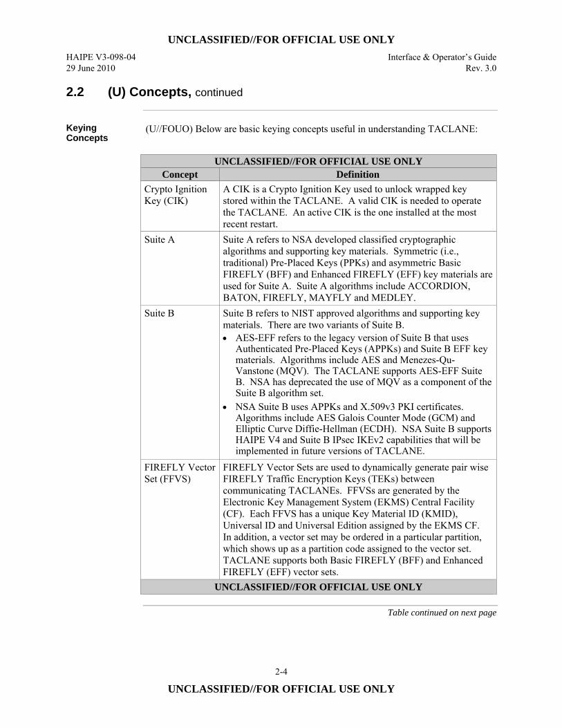
Keying Concepts
(U//FOUO) Below are basic keying concepts useful in understanding TACLANE:
UNCLASSIFIED//FOR OFFICIAL USE ONLY
Concept Definition Crypto Ignition Key (CIK)
A CIK is a Crypto Ignition Key used to unlock wrapped key stored within the TACLANE. A valid CIK is needed to operate the TACLANE. An active CIK is the one installed at the most recent restart.
Suite A Suite A refers to NSA developed classified cryptographic algorithms and supporting key materials. Symmetric (i.e., traditional) Pre-Placed Keys (PPKs) and asymmetric Basic FIREFLY (BFF) and Enhanced FIREFLY (EFF) key materials are used for Suite A. Suite A algorithms include ACCORDION, BATON, FIREFLY, MAYFLY and MEDLEY.
Suite B Suite B refers to NIST approved algorithms and supporting key materials. There are two variants of Suite B. • AES-EFF refers to the legacy version of Suite B that uses
Authenticated Pre-Placed Keys (APPKs) and Suite B EFF key materials. Algorithms include AES and Menezes-Qu-Vanstone (MQV). The TACLANE supports AES-EFF Suite B. NSA has deprecated the use of MQV as a component of the Suite B algorithm set.
• NSA Suite B uses APPKs and X.509v3 PKI certificates. Algorithms include AES Galois Counter Mode (GCM) and Elliptic Curve Diffie-Hellman (ECDH). NSA Suite B supports HAIPE V4 and Suite B IPsec IKEv2 capabilities that will be implemented in future versions of TACLANE.
FIREFLY Vector Set (FFVS)
FIREFLY Vector Sets are used to dynamically generate pair wise FIREFLY Traffic Encryption Keys (TEKs) between communicating TACLANEs. FFVSs are generated by the Electronic Key Management System (EKMS) Central Facility (CF). Each FFVS has a unique Key Material ID (KMID), Universal ID and Universal Edition assigned by the EKMS CF. In addition, a vector set may be ordered in a particular partition, which shows up as a partition code assigned to the vector set. TACLANE supports both Basic FIREFLY (BFF) and Enhanced FIREFLY (EFF) vector sets.
UNCLASSIFIED//FOR OFFICIAL USE ONLY
Table continued on next page
UNCLASSIFIED//FOR OFFICIAL USE ONLY Interface & Operator’s Guide HAIPE V3-098-04 Rev. 3.0 29 June 2010
2-5
UNCLASSIFIED//FOR OFFICIAL USE ONLY
2.2 (U) Concepts, continued
Keying Concepts (Cont.)
UNCLASSIFIED//FOR OFFICIAL USE ONLY Concept Definition
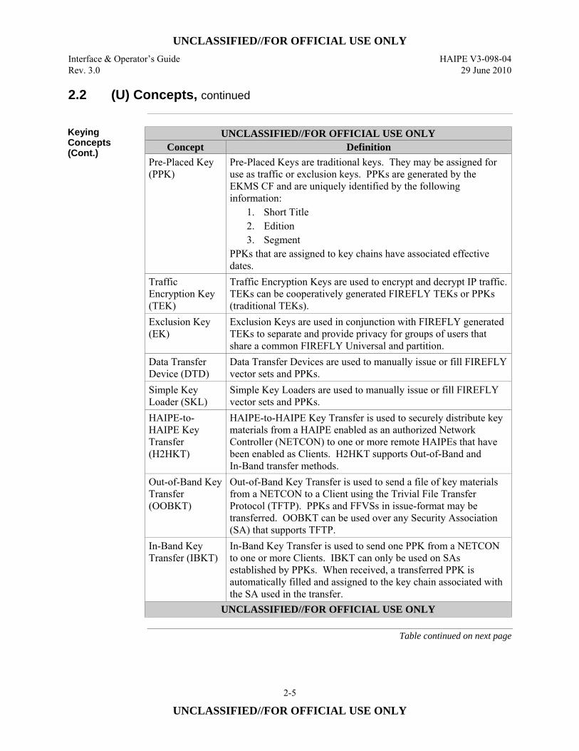
Pre-Placed Key (PPK)
Pre-Placed Keys are traditional keys. They may be assigned for use as traffic or exclusion keys. PPKs are generated by the EKMS CF and are uniquely identified by the following information:
1. Short Title 2. Edition 3. Segment
PPKs that are assigned to key chains have associated effective dates.
Traffic Encryption Key (TEK)
Traffic Encryption Keys are used to encrypt and decrypt IP traffic. TEKs can be cooperatively generated FIREFLY TEKs or PPKs (traditional TEKs).
Exclusion Key (EK)
Exclusion Keys are used in conjunction with FIREFLY generated TEKs to separate and provide privacy for groups of users that share a common FIREFLY Universal and partition.
Data Transfer Device (DTD)
Data Transfer Devices are used to manually issue or fill FIREFLY vector sets and PPKs.
Simple Key Loader (SKL)
Simple Key Loaders are used to manually issue or fill FIREFLY vector sets and PPKs.
HAIPE-to-HAIPE Key Transfer (H2HKT)
HAIPE-to-HAIPE Key Transfer is used to securely distribute key materials from a HAIPE enabled as an authorized Network Controller (NETCON) to one or more remote HAIPEs that have been enabled as Clients. H2HKT supports Out-of-Band and In-Band transfer methods.
Out-of-Band Key Transfer (OOBKT)
Out-of-Band Key Transfer is used to send a file of key materials from a NETCON to a Client using the Trivial File Transfer Protocol (TFTP). PPKs and FFVSs in issue-format may be transferred. OOBKT can be used over any Security Association (SA) that supports TFTP.
In-Band Key Transfer (IBKT)
In-Band Key Transfer is used to send one PPK from a NETCON to one or more Clients. IBKT can only be used on SAs established by PPKs. When received, a transferred PPK is automatically filled and assigned to the key chain associated with the SA used in the transfer.
UNCLASSIFIED//FOR OFFICIAL USE ONLY
Table continued on next page
UNCLASSIFIED//FOR OFFICIAL USE ONLY HAIPE V3-098-04 Interface & Operator’s Guide 29 June 2010 Rev. 3.0
2-6
UNCLASSIFIED//FOR OFFICIAL USE ONLY
2.2 (U) Concepts, continued
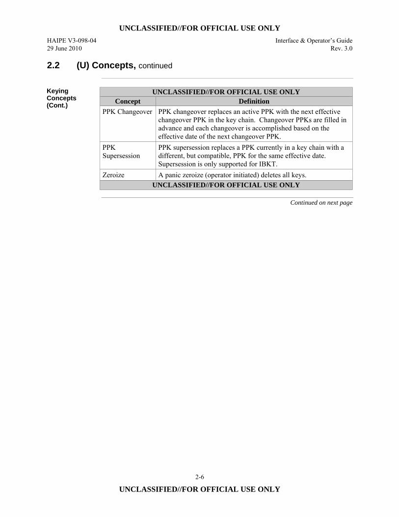
Keying Concepts (Cont.)
UNCLASSIFIED//FOR OFFICIAL USE ONLY Concept Definition
PPK Changeover PPK changeover replaces an active PPK with the next effective changeover PPK in the key chain. Changeover PPKs are filled in advance and each changeover is accomplished based on the effective date of the next changeover PPK.
PPK Supersession
PPK supersession replaces a PPK currently in a key chain with a different, but compatible, PPK for the same effective date. Supersession is only supported for IBKT.
Zeroize A panic zeroize (operator initiated) deletes all keys. UNCLASSIFIED//FOR OFFICIAL USE ONLY
Continued on next page
UNCLASSIFIED//FOR OFFICIAL USE ONLY Interface & Operator’s Guide HAIPE V3-098-04 Rev. 3.0 29 June 2010
2-7
UNCLASSIFIED//FOR OFFICIAL USE ONLY
2.2 (U) Concepts, continued
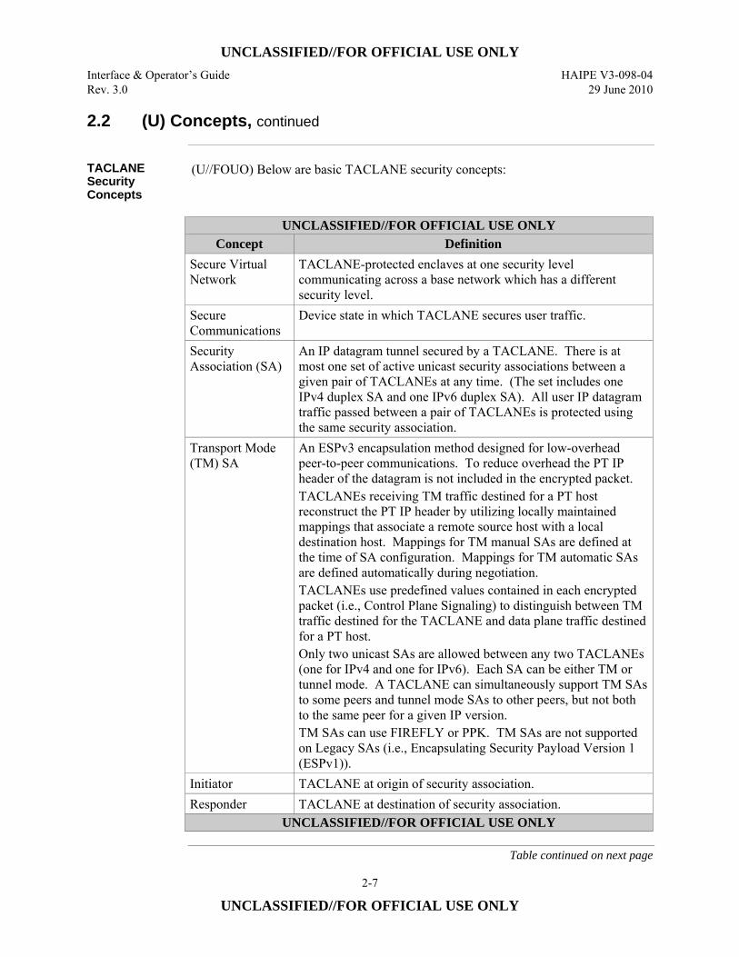
TACLANE Security Concepts
(U//FOUO) Below are basic TACLANE security concepts:
UNCLASSIFIED//FOR OFFICIAL USE ONLY
Concept Definition Secure Virtual Network
TACLANE-protected enclaves at one security level communicating across a base network which has a different security level.
Secure Communications
Device state in which TACLANE secures user traffic.
Security Association (SA)
An IP datagram tunnel secured by a TACLANE. There is at most one set of active unicast security associations between a given pair of TACLANEs at any time. (The set includes one IPv4 duplex SA and one IPv6 duplex SA). All user IP datagram traffic passed between a pair of TACLANEs is protected using the same security association.
Transport Mode (TM) SA
An ESPv3 encapsulation method designed for low-overhead peer-to-peer communications. To reduce overhead the PT IP header of the datagram is not included in the encrypted packet. TACLANEs receiving TM traffic destined for a PT host reconstruct the PT IP header by utilizing locally maintained mappings that associate a remote source host with a local destination host. Mappings for TM manual SAs are defined at the time of SA configuration. Mappings for TM automatic SAs are defined automatically during negotiation. TACLANEs use predefined values contained in each encrypted packet (i.e., Control Plane Signaling) to distinguish between TM traffic destined for the TACLANE and data plane traffic destined for a PT host. Only two unicast SAs are allowed between any two TACLANEs (one for IPv4 and one for IPv6). Each SA can be either TM or tunnel mode. A TACLANE can simultaneously support TM SAs to some peers and tunnel mode SAs to other peers, but not both to the same peer for a given IP version. TM SAs can use FIREFLY or PPK. TM SAs are not supported on Legacy SAs (i.e., Encapsulating Security Payload Version 1 (ESPv1)).
Initiator TACLANE at origin of security association. Responder TACLANE at destination of security association.
UNCLASSIFIED//FOR OFFICIAL USE ONLY
Table continued on next page
UNCLASSIFIED//FOR OFFICIAL USE ONLY HAIPE V3-098-04 Interface & Operator’s Guide 29 June 2010 Rev. 3.0
2-8
UNCLASSIFIED//FOR OFFICIAL USE ONLY
2.2 (U) Concepts, continued
TACLANE Security Concepts (Cont.)
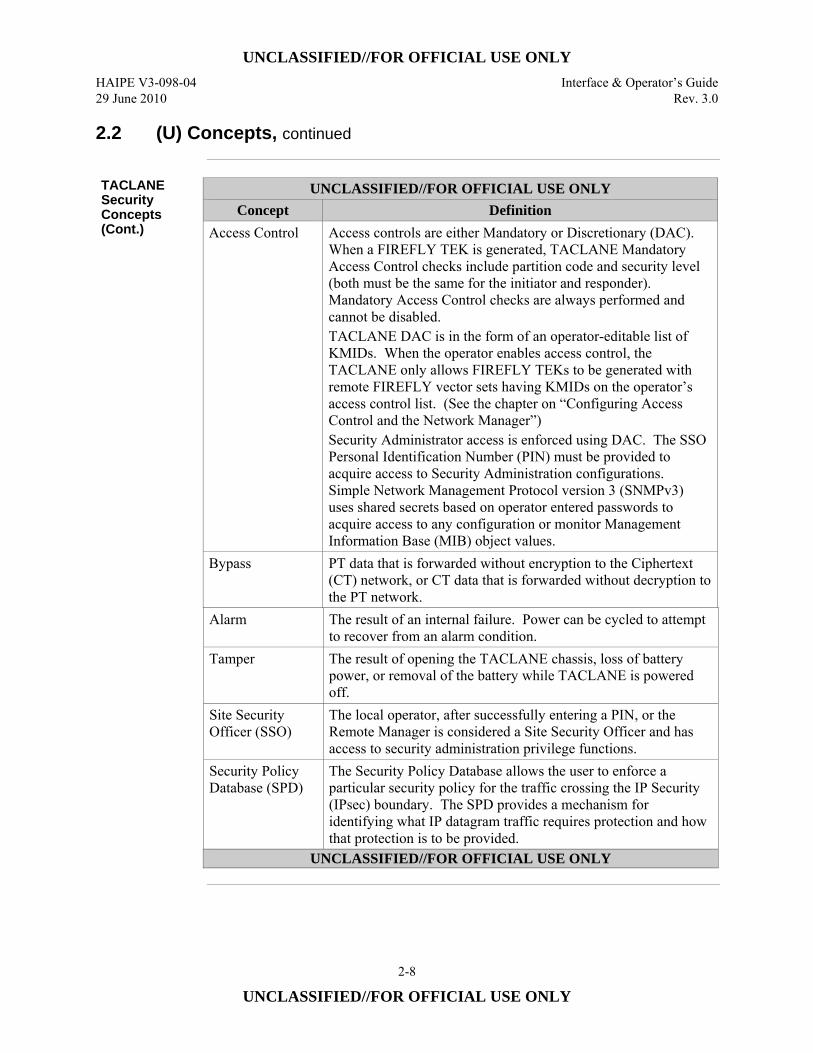
UNCLASSIFIED//FOR OFFICIAL USE ONLY Concept Definition
Access Control Access controls are either Mandatory or Discretionary (DAC). When a FIREFLY TEK is generated, TACLANE Mandatory Access Control checks include partition code and security level (both must be the same for the initiator and responder). Mandatory Access Control checks are always performed and cannot be disabled. TACLANE DAC is in the form of an operator-editable list of KMIDs. When the operator enables access control, the TACLANE only allows FIREFLY TEKs to be generated with remote FIREFLY vector sets having KMIDs on the operator’s access control list. (See the chapter on “Configuring Access Control and the Network Manager”) Security Administrator access is enforced using DAC. The SSO Personal Identification Number (PIN) must be provided to acquire access to Security Administration configurations. Simple Network Management Protocol version 3 (SNMPv3) uses shared secrets based on operator entered passwords to acquire access to any configuration or monitor Management Information Base (MIB) object values.
Bypass PT data that is forwarded without encryption to the Ciphertext (CT) network, or CT data that is forwarded without decryption to the PT network.
Alarm The result of an internal failure. Power can be cycled to attempt to recover from an alarm condition.
Tamper The result of opening the TACLANE chassis, loss of battery power, or removal of the battery while TACLANE is powered off.
Site Security Officer (SSO)
The local operator, after successfully entering a PIN, or the Remote Manager is considered a Site Security Officer and has access to security administration privilege functions.
Security Policy Database (SPD)
The Security Policy Database allows the user to enforce a particular security policy for the traffic crossing the IP Security (IPsec) boundary. The SPD provides a mechanism for identifying what IP datagram traffic requires protection and how that protection is to be provided.
UNCLASSIFIED//FOR OFFICIAL USE ONLY
UNCLASSIFIED//FOR OFFICIAL USE ONLY Interface & Operator’s Guide HAIPE V3-098-04 Rev. 3.0 29 June 2010
2-9
UNCLASSIFIED//FOR OFFICIAL USE ONLY
2.3 (U) Capabilities
Periods Processing at Multiple Levels
(U//FOUO) TACLANE can communicate at multiple security levels, one level at any given time. The SSO-privileged operator selects the security level. TACLANE products do not support multilevel FIREFLY Vector Sets. The classification level of the vector set must match the operating level of the TACLANE to be activated.
Easy to Use (U//FOUO) The TACLANE Human-Machine Interface (HMI) is web-browser
based. It uses the menu structure of the simple menu interface common to all TACLANE models. The HMI is accessed by connecting a PC, running browser software, to the TACLANE and entering the IP address of the TACLANE HMI into the browser address window. (U//FOUO) On the TACLANE-Micro a front panel RJ-45 Ethernet port is provided for a Console (i.e., the PC). A CAT-5 cable is needed to connect the PC and TACLANE Ethernet ports. The PC must provide an Ethernet port. (U//FOUO) On the TACLANE-GigE a front panel nine-pin D connector is provided for HMI. An RS-232 serial cable with male connectors (included with the unit) is used to connect the PC and the TACLANE-GigE’s RS-232 port. The PC must have RS-232 serial port hardware and point-to-point communication software to support IP connection with the TACLANE HMI. (U//FOUO) Refer to Section 2.4 (“Web-based Human-Machine Interface (HMI)”) for more details on the TACLANE HMI. (U//FOUO) Multiple instances of the web-browser running on the operator’s terminal can access a TACLANE HMI at the same time. This allows multiple status screens to be displayed at the same time another screen is being used to configure the TACLANE (command screen). This may be helpful, for example, in making configuration changes based on audit log entries or status displays. Status screens have to be manually refreshed to maintain currency. Managing a TACLANE through multiple instances of the web-browser in a time-interleaved fashion could cause command errors (multiple command screens). These errors necessitate the operator reissuing a command if one or more commands are made from other instances between the loading of a command screen and execution of the command.
CIK Management
(U//FOUO) The CIKs control access to the functionality of the TACLANE, and protect the encryption keys that have been filled into the TACLANE. An SSO-privileged operator can create up to two additional CIKs. These three CIKs can be used to allow multiple operators, independent, one-at-a-time access to a TACLANE. An SSO-privileged operator can delete any CIK except the active CIK, the CIK inserted when the TACLANE most recently started or restarted.
Continued on next page
UNCLASSIFIED//FOR OFFICIAL USE ONLY HAIPE V3-098-04 Interface & Operator’s Guide 29 June 2010 Rev. 3.0
2-10
UNCLASSIFIED//FOR OFFICIAL USE ONLY
2.3 (U) Capabilities, continued
Access Control (U//FOUO) The Mandatory Access Control function checks the following before
initiating FIREFLY TEK generation: • Partition code of FIREFLY vector set • Current security level of TACLANE
These must be the same for the initiator and the responder TACLANE. (U//FOUO) The operator-selectable, Discretionary Access Control function checks the operator-editable Access Control List (ACL) which contains a list of KMIDs (FIREFLY TEKs are only generated with remote FIREFLY vector sets having KMIDs on the ACL). (U//FOUO) Functional access control is provided through the use of the CIK. When the CIK is removed, the TACLANE resets, causing all security associations (traffic and management connections) to be lost. The TACLANE then proceeds through a power-up sequence, pausing until a valid CIK is inserted. When a valid CIK is inserted, the TACLANE resumes the power-up sequence, returning to the device state in which it was operating immediately before the CIK was removed (Auto-Recovery).
National Security Agency (NSA) – Certified Type 1
(U//FOUO) TACLANE is National Security Agency – certified to provide Type 1 encryption and decryption for information classified TOP SECRET codeword and below. When a valid CIK is inserted, the TACLANE is classified at the highest classification level of the key it contains. When the CIK is removed, the TACLANE is UNCLASSIFIED, but remains a Controlled Cryptographic Item (CCI), and the CIK is UNCLASSIFIED.
Field Software Upgrade (FSU) and Field Tamper Recovery (FTR)
(U//FOUO) The TACLANE software supports local and remote Field Software Upgrade and local Field Tamper Recovery capabilities. FSU allows an SSO to upgrade the software in a TACLANE from an UNCLASSIFIED encrypted image on a Compact Disc (CD). FTR enables an SSO to recover a TACLANE from a benign tamper using a classified SECRET Recovery CIK. Both features help reduce downtime since units no longer need to be sent to the depot for software upgrades or tamper recoveries. Please see the sections on “Performing a Field Software Upgrade” and “Performing a Field Tamper Recovery” for more information.
Continued on next page
UNCLASSIFIED//FOR OFFICIAL USE ONLY Interface & Operator’s Guide HAIPE V3-098-04 Rev. 3.0 29 June 2010
2-11
UNCLASSIFIED//FOR OFFICIAL USE ONLY
2.3 (U) Capabilities, continued
Change Software Signature
(U//FOUO) The TACLANE software supports local and remote Change Signature Commands (CSC). This allows an SSO to change software signature parameters in a TACLANE from an UNCLASSIFIED image on a disk. This feature allows different Community of Interests (COI) software signature parameters to be upgraded in the field. Please see the sections on “Change Software Signature” for more information.
IP Traffic Flow Security (TFS)
(U//FOUO) TACLANE software incorporates IP Traffic Flow Security features in accordance with HAIPE 3.1.2. These features prevent/reduce compromise of sensitive information due to certain types of attacks. Configuration of IP TFS parameters is restricted to the SSO or Remote Manager. Some of the IP TFS features are defined at the box (INE) level and some are defined on a per SA level. (U//FOUO) The box level IP TFS features include: • Fixed Packet Length (FPL) for outgoing CT encrypted traffic • Internet Group Management Protocol (IGMP) bypass control • Path Maximum Transmission Unit (PMTU) bypass control.
(U//FOUO) The per SA IP TFS features include: • Type-of-Service (including Differentiated Services Code Point (DSCP)) bypass
control • Don’t Fragment (DF) Bit bypass control • Explicit Congestion Notification (ECN) • Flow Label Bypass (IPv6)
(U//FOUO) Please see the chapters on “Configuring IP Traffic Flow Security Parameters”, “Security Policy Database” and “Configuring/Managing Security Associations” for more information.
Security Policy Database (SPD) & Security Association Database (SAD)
(U//FOUO) TACLANE supports the HAIPE IS version 3.1.2 Security Policy Database and Security Association Database. The SPD rules determine what packets are allowed into and out of the INE, and whether the packets that are allowed in require protection (encryption). The SAD defines parameters associated with each SA supported by the INE. (U//FOUO) Please see the chapters on “Security Policy Database” and “Configuring/Managing Security Associations” for more information.
Continued on next page
UNCLASSIFIED//FOR OFFICIAL USE ONLY HAIPE V3-098-04 Interface & Operator’s Guide 29 June 2010 Rev. 3.0
2-12
UNCLASSIFIED//FOR OFFICIAL USE ONLY
2.3 (U) Capabilities, continued
Remote Management – Supported SNMP MIBs
(U) TACLANE functionality can be remotely managed by the General Dynamics Encryptor Manager (GEM) X™3, or an equivalent SNMPv3 Network Manager. The TACLANE provides standardized MIBs in support of SNMPv3. (U) Objects from the MIBs registered under the Object Identifier (OID) structure {iso(1) identified-organization(3) dod(6) internet(1) private(4) enterprise(1)} (or equivalently 1.3.6.1.4.1 in dot format) and listed below are supported: • 1.3.6.1.4.1.576: GDC4S – Assignments
– 1.3.6.1.4.1.576.24: GDC4S – Encryption – Products – 1.3.6.1.4.1.576.24.1.1.1.3: TACLANE – Products – Registration – 1.3.6.1.4.1.576.24.2: GDC4S-Encryption-Products – Common – 1.3.6.1.4.1.576.24.2.2: GDC4S – Common – Notifications – 1.3.6.1.4.1.576.24.3.1: Network Encryptor – Enterprise
• 1.3.6.1.4.1.21079: HAIPE – Enterprise – MIB – 1.3.6.1.4.1.21079.4: HAIPE – Feature-Hierarchy – 1.3.6.1.4.1.21079.4.1: HAIPE – Traffic Protection – 1.3.6.1.4.1.21079.4.1.6: HAIPE – Key – Transfer – 1.3.6.1.4.1.21079.4.2: HAIPE – Networking – 1.3.6.1.4.1.21079.4.2.3: HAIPE – Networking – Discovery – 1.3.6.1.4.1.21079.4.3: HAIPE – Management
(U//FOUO) Objects from the following MIBs listed by OID and defined by IETF RFCs are supported • 1.3.6.1.2.1: SNMP MIB-2
– 1.3.6.1.2.1.1: System, RFC 3418 – 1.3.6.1.2.1.2: Interface, RFC 2863 – 1.3.6.1.2.1.4: Internet Protocol, RFC 4293 – 1.3.6.1.2.1.4.24: IP – Forward, RFC 4292 – 1.3.6.1.2.1.25: Host – Resources, RFC 2790 – 1.3.6.1.2.1.92: Notification – Log, RFC 3014,
• 1.3.6.1.6.3: SNMPv2 Modules – 1.3.6.1.6.3.10: SNMP – Framework, RFC 3411 – 1.3.6.1.6.3.11: SNMP – MPD, RFC 3412 – 1.3.6.1.6.3.12: SNMP – Target, RFC 3413 – 1.3.6.1.6.3.13: SNMP – Notification, RFC 3413 – 1.3.6.1.6.3.15: SNMP – USM, RFC 3414 – 1.3.6.1.6.3.16: SNMP – VACM, RFC 3415 – 1.3.6.1.6.3.20: SNMP – USM – AES, RFC 3826
Continued on next page
3 (U) GEM X is a trademark of General Dynamics.
UNCLASSIFIED//FOR OFFICIAL USE ONLY Interface & Operator’s Guide HAIPE V3-098-04 Rev. 3.0 29 June 2010
2-13
UNCLASSIFIED//FOR OFFICIAL USE ONLY
2.3 (U) Capabilities, continued
Remote Management – Features
(U//FOUO) The TACLANE is designed such that up to twelve remote security managers have the same management capabilities as are provided to the local SSO manager with the exception of creating a CIK and setting the security level. These capabilities include: • PPK Assignment Table management • PPK Chain Assignment management • Security Audit Log and Event Log management • Static Routing Table management • Device Date and Time management • Device State management • Trap management • Device statistics management • Firmware Download and Installation management • TFS management • Security Association/Host Table management • Security Association Database management • Security Policy Database management • Discretionary Access Control management • Interface IP Address management. • Change Signature Command (S^2) Download and Installation management • Programmable PACing & Privileges (P^3) management
Remote Management –Security
(U//FOUO) TACLANE can be managed from the PT or CT side. Regardless of whether the Remote Manager is on the CT-side or the PT-side, SNMPv3 privacy and authentication protection is provided to all management traffic. In addition, CT-side management traffic is encrypted between the TACLANE fronting the Remote Management Workstation and the managed TACLANE. (U//FOUO) Information on configuring TACLANE for remote management is in the section titled “Configuring the Network Manager”. Please refer to the appropriate GEM X Operator’s Manual for more information on configuring the HAIPE device fronting the GEM X and for more information on the GEM X Remote Management software.
Continued on next page
UNCLASSIFIED//FOR OFFICIAL USE ONLY HAIPE V3-098-04 Interface & Operator’s Guide 29 June 2010 Rev. 3.0
2-14
UNCLASSIFIED//FOR OFFICIAL USE ONLY
2.3 (U) Capabilities, continued
Out-Of-Band Key Transfer
(U//FOUO) TACLANE is designed to support OOBKT as a Client, a NETCON, or both. It stores up to 30 keys (nominally 24 PPKs and 6 FFVSs) in issue-format. These keys can be locally issued to the TACLANE using a DTD or SKL and exchanged between TACLANEs using OOBKT. (U//FOUO) TACLANE OOBKT NETCONs allow a user to define up to 24 key files for OOBKT. Each file can contain up to 12 PPKs (Suite A and/or B) or 1 FFVS in issue-format. The TACLANE can be configured to support up to 96 OOBKT Clients. OOBKT is accomplished using TFTP over any shared SA pair between the NETCON and Client. The keys transferred can be classified up to the classification level of the shared Transfer SA. (U//FOUO) TACLANE OOBKT Clients can be configured to accept key transfers from up to 12 different OOBKT NETCONs. Key files are received using TFTP and the transferred keys are automatically issued to and stored in the Client TACLANE.
In-Band Key Transfer
(U//FOUO) TACLANE is designed to support IBKT as a Client, a NETCON, or both. (U//FOUO) A TACLANE IBKT NETCON allows the user to schedule up to 240 automatically executed tasks to deliver a PPK (from the local store of issued keys) to a specified Client CT IP address. The user can assign an effective date to the transferred key that is current or up to 11 months into the future. Each task begins at a specified transfer time and repeats transfers a specified number of times with a specified retry period. The TACLANE will automatically send IBKT packets over an ESPv3 Transfer SA from the NETCON to the Client established by a PPK chain. The Transfer SA has to share the same classification and suite (i.e., A or B) as the key being delivered. Once all scheduled transfers are complete, the TACLANE IBKT NETCON automatically fills the transferred PPK to its own PPK chain associated with the Transfer SA and initiates its use in accordance with the assigned effective date. (U//FOUO) A TACLANE IBKT Client allows a user to designate up to 12 IBKT NETCONs as authorized controllers. The TACLANE will automatically accept an IBKT packet received from a designated NETCON and process it to extract and validate the contained PPK. The TACLANE IBKT Client will automatically fill a valid PPK, assign it to the PPK chain associated with the Transfer SA and put it into use per its effective date. A user may prevent IBKT supersession of an existing key in a PPK chain by listing it in a disabled key table that accommodates up to 72 entries.
Continued on next page
UNCLASSIFIED//FOR OFFICIAL USE ONLY Interface & Operator’s Guide HAIPE V3-098-04 Rev. 3.0 29 June 2010
2-15
UNCLASSIFIED//FOR OFFICIAL USE ONLY
2.3 (U) Capabilities, continued
Routing Information Protocol
(U//FOUO) The Routing Information Protocol capability enables the TACLANE to transmit and receive RIP messages with peer networking devices located on the PT interface. The TACLANE, using RIP, is able receive information in RIP advertisements from routers located on PT interface. The TACLANE uses this information to build a database of the networks that it protects, and to inform other TACLANEs or HAIPE devices what networks or hosts the TACLANE protects. The TACLANE is also able to transmit RIP advertisements to peer networking devices on the PT network conveying information about remote PT networks which the TACLANE can reach through established Security Associations
Network Address Translation-Traversal (NAT-T)
(U//FOUO) The NAT-T capability permits the TACLANE to establish connections through Network Address Translation (NAT) devices. The NAT-T capability allows a TACLANE which is initiating a connection on the private side of a NAT device to establish a Security Association with a Remote TACLANE located on the public side of the NAT device.
Generic Discovery Client
(U//FOUO) TACLANE supports the capability to act as a Generic Discovery Client. It can be configured with the PT IP addresses of up to eight Generic Discovery Servers with which it will register its local enclave PT IP address/prefix information. It supports the identification of up to 32 remote PT IP addresses from which it can solicit discovery information. The TACLANE can also be configured with up to eight IP addresses that it will listen to for solicitation queries sent by other HAIPEs acting as GDCs and respond to received solicitations when it has the identified PT IP address in its local enclave.
Implicit Peer Enclave Prefix Discovery
(U//FOUO) TACLANE provides an IM-PEPD capability that supports both basic and segmented core modes of operation. Operation of IM-PEPD can be configured locally through the HMI or remotely using SNMP. An operator can also configure Community of Interest (COI) and Subnet parameters needed for the derivation of IP addresses used with IM-PEPD through the HMI or SNMP.
. Peer Destination Unreachable Notification
(U//FOUO) TACLANE provides an SSO with the capability to configure PDUN capability for individual PPK and FF SAs.
Peer HAIPE Reachability Detection
(U//FOUO) TACLANE provides PHRD capability for individual PPK and FF SAs. When enabled, the rate of PHRD echo message transmission and the threshold number of PHRD retries to declare a peer unreachable can be set for each SA.
UNCLASSIFIED//FOR OFFICIAL USE ONLY HAIPE V3-098-04 Interface & Operator’s Guide 29 June 2010 Rev. 3.0
2-16
UNCLASSIFIED//FOR OFFICIAL USE ONLY
2.4 (U) Web-based Human-Machine Interface (HMI)
Introduction (U//FOUO) This section applies to TACLANEs that support a local operator through
the console port.
Web-Browser-Based HMI
(U//FOUO) The HMI in the TACLANE provides the local operator a web-browser-based replacement to the simple menu interface common to previous TACLANE models. This HMI requires a Personal Computer (PC) running a web-browser application be connected to the TACLANE. (The HMI is designed for Microsoft Corp’s Internet Explorer® version 7.0, although other browsers may provide satisfactory performance.) PC configuration differs depending on whether a TACLANE-Micro or TACLANE-GigE is being connected.
• (U//FOUO) For the TACLANE-Micro, the PC uses an Ethernet port to communicate with the TACLANE-Micro console port. A standard Ethernet cable is used to connect the PC and TACLANE-Micro. The default IPv4 address for the TACLANE-Micro console port is 172.16.0.1. This address is entered in the address window of the web-browser to allow access to the TACLANE HMI by the local operator. This address is modifiable. See section “Entering/Modifying the TACLANE IPv4 Network Configuration”. (U//FOUO) The PC’s Ethernet address must be on the 172.16 network to enable communication with the TACLANE-Micro. (U//FOUO) The HMI console Ethernet is designed for full duplex operation, where the console is directly connected to the TACLANE. Note: (U//FOUO) Use of a Hub on the console interface may result in receive buffer lockups caused by Ethernet errors. Recovery requires the TACLANE to be restarted.
• (U//FOUO) For the TACLANE-GigE, the PC uses a serial port to communicate with the TACLANE. An RS-232 serial cable with 9-pin D connectors is used to connect the PC and TACLANE-GigE. The serial port should be set to operate at 115,200 baud with 8 data, no parity, and 1 stop bit. It may be necessary to command the serial port to CONNECT to enable this connection. The IPv4 address for the TACLANE-GigE HMI port is 172.16.1.1. This address is entered in the address window of the web-browser to allow access to the TACLANE HMI by the local operator. This address is not modifiable.
(U//FOUO) The operator interface flows were followed to enable existing TACLANE (GigE/Mini/Classic/E100) operators to use TACLANE products without retraining. The larger screen area of the display allows the presentation of descriptive command names, status messages and data labels, in addition to on-screen help. This improved display provides an intuitive HMI for new operators.
Continued on next page
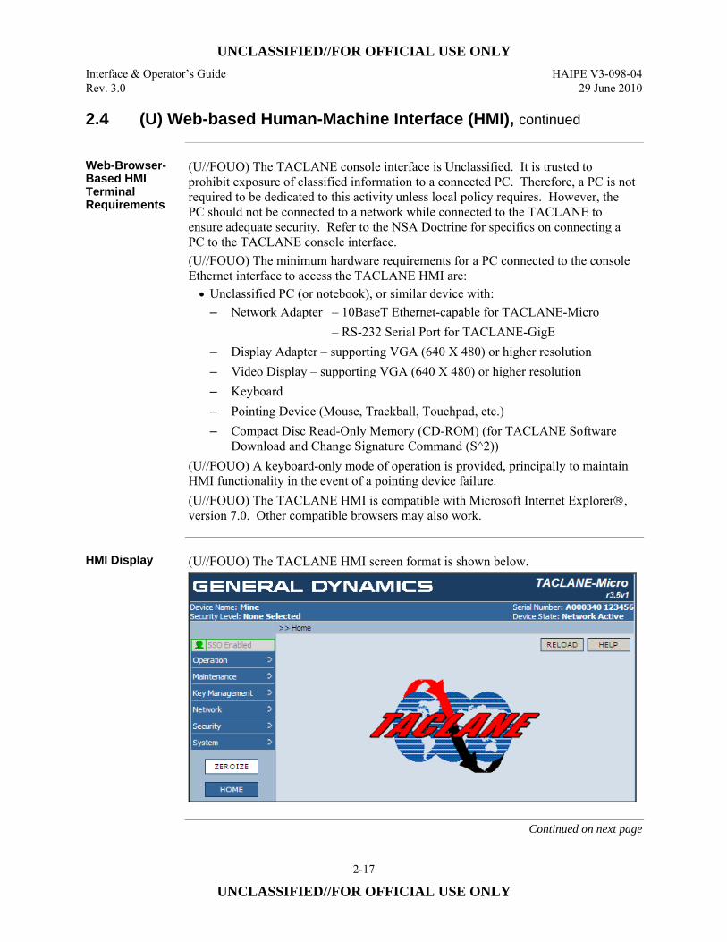
UNCLASSIFIED//FOR OFFICIAL USE ONLY Interface & Operator’s Guide HAIPE V3-098-04 Rev. 3.0 29 June 2010
2-17
UNCLASSIFIED//FOR OFFICIAL USE ONLY
2.4 (U) Web-based Human-Machine Interface (HMI), continued
Web-Browser-Based HMI Terminal Requirements
(U//FOUO) The TACLANE console interface is Unclassified. It is trusted to prohibit exposure of classified information to a connected PC. Therefore, a PC is not required to be dedicated to this activity unless local policy requires. However, the PC should not be connected to a network while connected to the TACLANE to ensure adequate security. Refer to the NSA Doctrine for specifics on connecting a PC to the TACLANE console interface. (U//FOUO) The minimum hardware requirements for a PC connected to the console Ethernet interface to access the TACLANE HMI are: • Unclassified PC (or notebook), or similar device with:
– Network Adapter – 10BaseT Ethernet-capable for TACLANE-Micro – RS-232 Serial Port for TACLANE-GigE
– Display Adapter – supporting VGA (640 X 480) or higher resolution – Video Display – supporting VGA (640 X 480) or higher resolution – Keyboard – Pointing Device (Mouse, Trackball, Touchpad, etc.) – Compact Disc Read-Only Memory (CD-ROM) (for TACLANE Software
Download and Change Signature Command (S^2)) (U//FOUO) A keyboard-only mode of operation is provided, principally to maintain HMI functionality in the event of a pointing device failure. (U//FOUO) The TACLANE HMI is compatible with Microsoft Internet Explorer®, version 7.0. Other compatible browsers may also work.
HMI Display (U//FOUO) The TACLANE HMI screen format is shown below.
Continued on next page
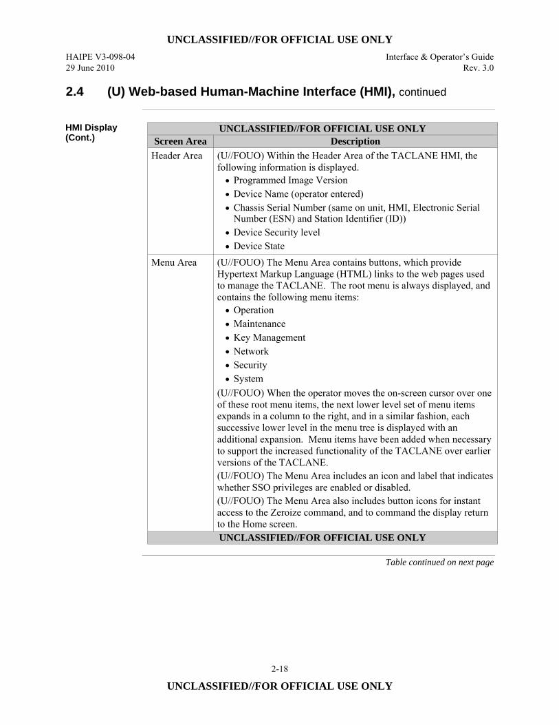
UNCLASSIFIED//FOR OFFICIAL USE ONLY HAIPE V3-098-04 Interface & Operator’s Guide 29 June 2010 Rev. 3.0
2-18
UNCLASSIFIED//FOR OFFICIAL USE ONLY
2.4 (U) Web-based Human-Machine Interface (HMI), continued
HMI Display (Cont.)
UNCLASSIFIED//FOR OFFICIAL USE ONLY Screen Area Description
Header Area (U//FOUO) Within the Header Area of the TACLANE HMI, the following information is displayed. • Programmed Image Version • Device Name (operator entered) • Chassis Serial Number (same on unit, HMI, Electronic Serial
Number (ESN) and Station Identifier (ID)) • Device Security level • Device State
Menu Area (U//FOUO) The Menu Area contains buttons, which provide Hypertext Markup Language (HTML) links to the web pages used to manage the TACLANE. The root menu is always displayed, and contains the following menu items: • Operation • Maintenance • Key Management • Network • Security • System
(U//FOUO) When the operator moves the on-screen cursor over one of these root menu items, the next lower level set of menu items expands in a column to the right, and in a similar fashion, each successive lower level in the menu tree is displayed with an additional expansion. Menu items have been added when necessary to support the increased functionality of the TACLANE over earlier versions of the TACLANE. (U//FOUO) The Menu Area includes an icon and label that indicates whether SSO privileges are enabled or disabled. (U//FOUO) The Menu Area also includes button icons for instant access to the Zeroize command, and to command the display return to the Home screen. UNCLASSIFIED//FOR OFFICIAL USE ONLY
Table continued on next page
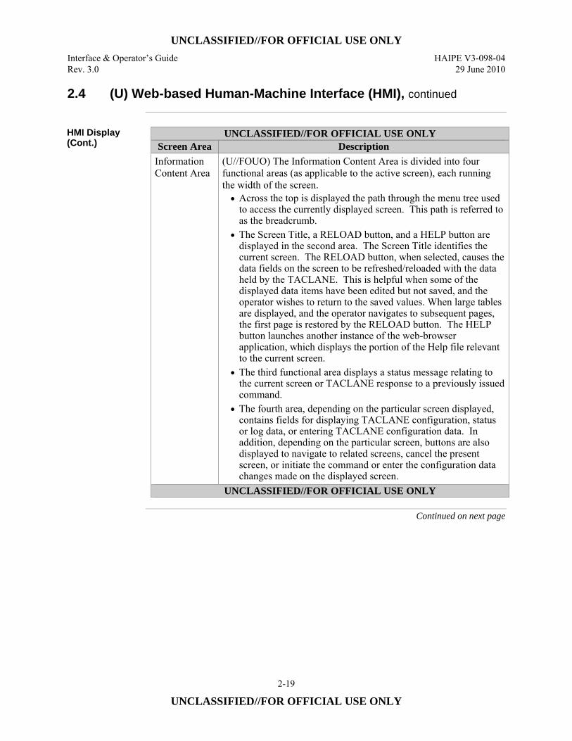
UNCLASSIFIED//FOR OFFICIAL USE ONLY Interface & Operator’s Guide HAIPE V3-098-04 Rev. 3.0 29 June 2010
2-19
UNCLASSIFIED//FOR OFFICIAL USE ONLY
2.4 (U) Web-based Human-Machine Interface (HMI), continued
HMI Display (Cont.)
UNCLASSIFIED//FOR OFFICIAL USE ONLY Screen Area Description
Information Content Area
(U//FOUO) The Information Content Area is divided into four functional areas (as applicable to the active screen), each running the width of the screen. • Across the top is displayed the path through the menu tree used
to access the currently displayed screen. This path is referred to as the breadcrumb.
• The Screen Title, a RELOAD button, and a HELP button are displayed in the second area. The Screen Title identifies the current screen. The RELOAD button, when selected, causes the data fields on the screen to be refreshed/reloaded with the data held by the TACLANE. This is helpful when some of the displayed data items have been edited but not saved, and the operator wishes to return to the saved values. When large tables are displayed, and the operator navigates to subsequent pages, the first page is restored by the RELOAD button. The HELP button launches another instance of the web-browser application, which displays the portion of the Help file relevant to the current screen.
• The third functional area displays a status message relating to the current screen or TACLANE response to a previously issued command.
• The fourth area, depending on the particular screen displayed, contains fields for displaying TACLANE configuration, status or log data, or entering TACLANE configuration data. In addition, depending on the particular screen, buttons are also displayed to navigate to related screens, cancel the present screen, or initiate the command or enter the configuration data changes made on the displayed screen.
UNCLASSIFIED//FOR OFFICIAL USE ONLY
Continued on next page

UNCLASSIFIED//FOR OFFICIAL USE ONLY HAIPE V3-098-04 Interface & Operator’s Guide 29 June 2010 Rev. 3.0
2-20
UNCLASSIFIED//FOR OFFICIAL USE ONLY
2.4 (U) Web-based Human-Machine Interface (HMI), continued
Automatic Scrolling
(U//FOUO) In some cases, the amount of information displayed extends beyond the bottom of the Information Content Area. In those cases, the operator may use the elevator on the right-hand of the browser window or a scroll device to scroll down to see the remainder of the screen. Side-to-side scrolling is typically not required to view the TACLANE screen.
UNCLASSIFIED//FOR OFFICIAL USE ONLY
Screen Area Description Screen Updates (U//FOUO) The time-variable information displayed in the
Header Area of the TACLANE HMI screens is updated periodically through a polling process under the control of the web-browser application. This ensures that the displayed Device Security Level and Device State are current. (U//FOUO) The fields in the fourth area of the Information Content Area, containing TACLANE configuration, status, or log data are not updated dynamically. Information is displayed as of the time a function is selected, i.e., the date/time screen does not change dynamically. These data fields can be updated by selecting the RELOAD button icon or selecting the screen from the menu. (U//FOUO) In the event another operator changes configuration data for a particular TACLANE between the time when the first operator last updated the screen, and when that first operator sends edits of the data on that screen, to the TACLANE, an error message and updated data will be returned to the first operator, and the first operator will have to reenter the edits.
UNCLASSIFIED//FOR OFFICIAL USE ONLY
‘SSO Privileged’ HMI Commands
(U//FOUO) These commands are noted in the “HMI Menu Tree” section of this manual.
Access to ‘SSO Privileged’ HMI Commands
(U//FOUO) Many HMI commands can be accessed by an operator but contain additional functionality for an SSO. This means that a user without SSO privileges ‘enabled’ can display the data for the command but a user that has SSO privileges ‘enabled’ has access to configure data via the command. SSO-privileges are enabled by entering the valid SSO PIN after obtaining functional access to the TACLANE. Refer to sections “Enable SSO Privileges”, “Disable SSO Privileges”, and “Generate SSO PIN” of this manual for more information.
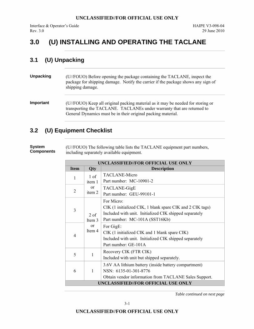
UNCLASSIFIED//FOR OFFICIAL USE ONLY Interface & Operator’s Guide HAIPE V3-098-04 Rev. 3.0 29 June 2010
3-1
UNCLASSIFIED//FOR OFFICIAL USE ONLY
3.0 (U) INSTALLING AND OPERATING THE TACLANE
3.1 (U) Unpacking
Unpacking (U//FOUO) Before opening the package containing the TACLANE, inspect the
package for shipping damage. Notify the carrier if the package shows any sign of shipping damage.
Important (U//FOUO) Keep all original packing material as it may be needed for storing or
transporting the TACLANE. TACLANEs under warranty that are returned to General Dynamics must be in their original packing material.
3.2 (U) Equipment Checklist
System Components
(U//FOUO) The following table lists the TACLANE equipment part numbers, including separately available equipment.
UNCLASSIFIED//FOR OFFICIAL USE ONLY
Item Qty Description
1 1 of item 1
or item 2
TACLANE-Micro Part number: MC-10901-2
2 TACLANE-GigE Part number: GEU-99101-1
3 2 of
Item 3 or
Item 4
For Micro: CIK (1 initialized CIK, 1 blank spare CIK and 2 CIK tags) Included with unit. Initialized CIK shipped separately Part number: MC-101A (SST16Kb)
4
For GigE: CIK (1 initialized CIK and 1 blank spare CIK) Included with unit. Initialized CIK shipped separately Part number: GE-101A
5 1 Recovery CIK (FTR CIK) Included with unit but shipped separately.
6 1 3.6V AA lithium battery (inside battery compartment) NSN: 6135-01-301-8776 Obtain vendor information from TACLANE Sales Support.
UNCLASSIFIED//FOR OFFICIAL USE ONLY
Table continued on next page
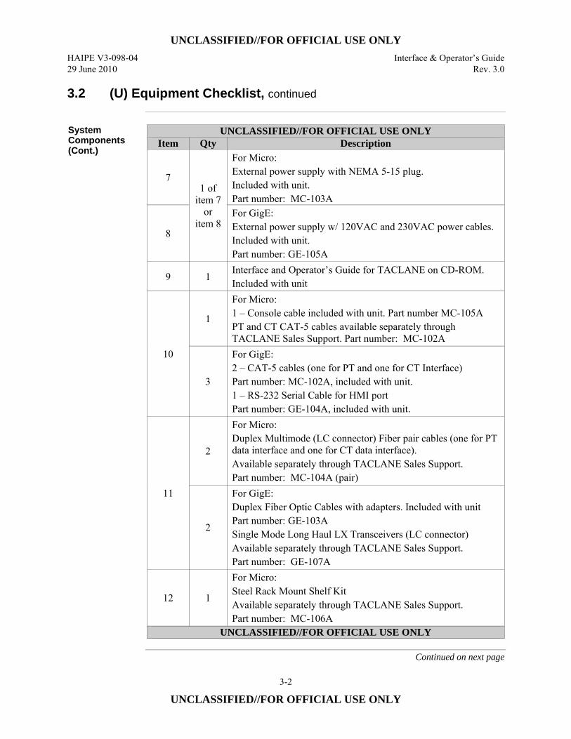
UNCLASSIFIED//FOR OFFICIAL USE ONLY HAIPE V3-098-04 Interface & Operator’s Guide 29 June 2010 Rev. 3.0
3-2
UNCLASSIFIED//FOR OFFICIAL USE ONLY
3.2 (U) Equipment Checklist, continued
System Components (Cont.)
UNCLASSIFIED//FOR OFFICIAL USE ONLY Item Qty Description
7 1 of
item 7 or
item 8
For Micro: External power supply with NEMA 5-15 plug. Included with unit. Part number: MC-103A
8
For GigE: External power supply w/ 120VAC and 230VAC power cables. Included with unit. Part number: GE-105A
9 1 Interface and Operator’s Guide for TACLANE on CD-ROM. Included with unit
10
1
For Micro: 1 – Console cable included with unit. Part number MC-105A PT and CT CAT-5 cables available separately through TACLANE Sales Support. Part number: MC-102A
3
For GigE: 2 – CAT-5 cables (one for PT and one for CT Interface) Part number: MC-102A, included with unit. 1 – RS-232 Serial Cable for HMI port Part number: GE-104A, included with unit.
11
2
For Micro: Duplex Multimode (LC connector) Fiber pair cables (one for PT data interface and one for CT data interface). Available separately through TACLANE Sales Support. Part number: MC-104A (pair)
2
For GigE: Duplex Fiber Optic Cables with adapters. Included with unit Part number: GE-103A Single Mode Long Haul LX Transceivers (LC connector) Available separately through TACLANE Sales Support. Part number: GE-107A
12 1
For Micro: Steel Rack Mount Shelf Kit Available separately through TACLANE Sales Support. Part number: MC-106A
UNCLASSIFIED//FOR OFFICIAL USE ONLY
Continued on next page
UNCLASSIFIED//FOR OFFICIAL USE ONLY Interface & Operator’s Guide HAIPE V3-098-04 Rev. 3.0 29 June 2010
3-3
UNCLASSIFIED//FOR OFFICIAL USE ONLY
3.2 (U) Equipment Checklist, continued
Initialized CIK (U//FOUO) A CIK is included when ordering a TACLANE. This CIK is shipped
separately from the TACLANE. This CIK is needed to operate the new TACLANE. The Key Storage Device (KSD – a blank CIK) that is shipped with the TACLANE unit will not allow you to initially operate the TACLANE. (U//FOUO) CIKs are TACLANE unit specific. For customers with more than one TACLANE unit, make sure to note the serial # of the TACLANE associated with each CIK. Do not attempt to use CIKs in alternate TACLANE units.
Recovery CIK (U//FOUO) A Recovery CIK, needed to perform Field Tamper Recovery, is included
when ordering a TACLANE. The Recovery CIK can be used to recover its associated TACLANE from a benign tamper (a maximum of five times) without returning it to the depot. The Recovery CIK is classified SECRET and is shipped separately from the TACLANE. If the TACLANE is sent to a COMSEC account, then the Recovery CIK will be sent to that account’s classified mailing address. If the TACLANE is sent to a Department of Defense Activity Address Code (DoDAAC), the Recovery CIK will be sent upon receipt of a valid classified mailing address for the receiving activity. (U//FOUO) Recovery CIKs are TACLANE unit specific. Please make sure to note the serial number of the TACLANE associated with the Recovery CIK. Do not attempt to use a Recovery CIK in TACLANE units other than the one with which it is associated.
Additional Equipment Required
(U//FOUO) The following items, not supplied with the TACLANE, are required for configuring the unit: • PC (or notebook) • Web-Browser Software, Microsoft Internet Explorer® version 7.0
(U//FOUO) The following items, not supplied with the TACLANE, are required for filling key: • DTD (AN/CYZ-10(V3)) NSN: 5810-01-393-1973 or SKL (AN/PYQ-10(C) )
NSN: 7010-01-517-3587 • Fill cable
Important CIK Note
(U//FOUO) The Key Storage Devices (KSD), used to create CIKs for the TACLANE-Micro, are 16 Kbit storage devices. (U//FOUO) The Key Storage Devices (KSD), used to create CIKs for the TACLANE-GigE, are 4 Kbit storage devices.
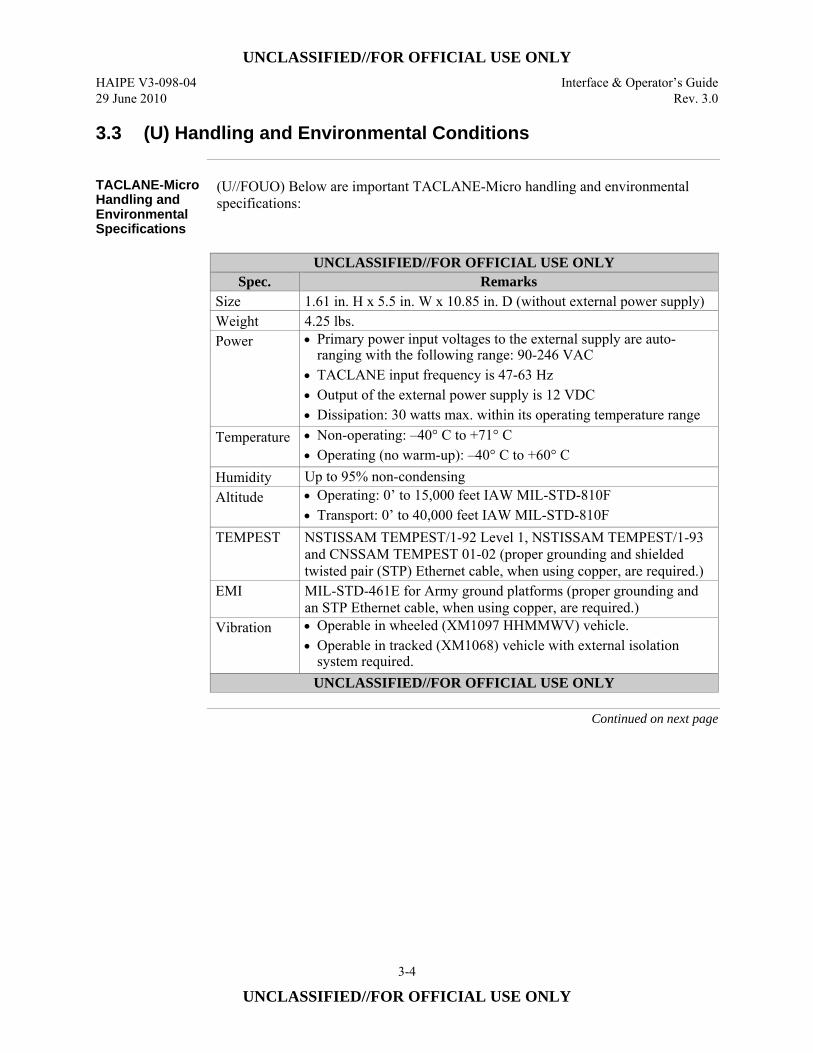
UNCLASSIFIED//FOR OFFICIAL USE ONLY HAIPE V3-098-04 Interface & Operator’s Guide 29 June 2010 Rev. 3.0
3-4
UNCLASSIFIED//FOR OFFICIAL USE ONLY
3.3 (U) Handling and Environmental Conditions
TACLANE-Micro Handling and Environmental Specifications
(U//FOUO) Below are important TACLANE-Micro handling and environmental specifications:
UNCLASSIFIED//FOR OFFICIAL USE ONLY
Spec. Remarks Size 1.61 in. H x 5.5 in. W x 10.85 in. D (without external power supply) Weight 4.25 lbs. Power • Primary power input voltages to the external supply are auto-
ranging with the following range: 90-246 VAC • TACLANE input frequency is 47-63 Hz • Output of the external power supply is 12 VDC • Dissipation: 30 watts max. within its operating temperature range
Temperature • Non-operating: –40° C to +71° C• Operating (no warm-up): –40° C to +60° C
Humidity Up to 95% non-condensing Altitude • Operating: 0’ to 15,000 feet IAW MIL-STD-810F
• Transport: 0’ to 40,000 feet IAW MIL-STD-810F TEMPEST NSTISSAM TEMPEST/1-92 Level 1, NSTISSAM TEMPEST/1-93
and CNSSAM TEMPEST 01-02 (proper grounding and shielded twisted pair (STP) Ethernet cable, when using copper, are required.)
EMI MIL-STD-461E for Army ground platforms (proper grounding and an STP Ethernet cable, when using copper, are required.)
Vibration • Operable in wheeled (XM1097 HHMMWV) vehicle. • Operable in tracked (XM1068) vehicle with external isolation
system required. UNCLASSIFIED//FOR OFFICIAL USE ONLY
Continued on next page
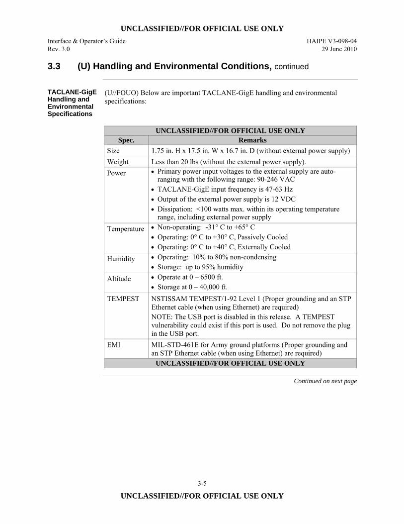
UNCLASSIFIED//FOR OFFICIAL USE ONLY Interface & Operator’s Guide HAIPE V3-098-04 Rev. 3.0 29 June 2010
3-5
UNCLASSIFIED//FOR OFFICIAL USE ONLY
3.3 (U) Handling and Environmental Conditions, continued
TACLANE-GigE Handling and Environmental Specifications
(U//FOUO) Below are important TACLANE-GigE handling and environmental specifications:
UNCLASSIFIED//FOR OFFICIAL USE ONLY
Spec. Remarks Size 1.75 in. H x 17.5 in. W x 16.7 in. D (without external power supply) Weight Less than 20 lbs (without the external power supply). Power • Primary power input voltages to the external supply are auto-
ranging with the following range: 90-246 VAC • TACLANE-GigE input frequency is 47-63 Hz • Output of the external power supply is 12 VDC • Dissipation: <100 watts max. within its operating temperature
range, including external power supply Temperature • Non-operating: -31° C to +65° C
• Operating: 0° C to +30° C, Passively Cooled • Operating: 0° C to +40° C, Externally Cooled
Humidity • Operating: 10% to 80% non-condensing• Storage: up to 95% humidity
Altitude • Operate at 0 – 6500 ft.• Storage at 0 – 40,000 ft.
TEMPEST NSTISSAM TEMPEST/1-92 Level 1 (Proper grounding and an STP Ethernet cable (when using Ethernet) are required) NOTE: The USB port is disabled in this release. A TEMPEST vulnerability could exist if this port is used. Do not remove the plug in the USB port.
EMI MIL-STD-461E for Army ground platforms (Proper grounding and an STP Ethernet cable (when using Ethernet) are required)
UNCLASSIFIED//FOR OFFICIAL USE ONLY
Continued on next page
UNCLASSIFIED//FOR OFFICIAL USE ONLY HAIPE V3-098-04 Interface & Operator’s Guide 29 June 2010 Rev. 3.0
3-6
UNCLASSIFIED//FOR OFFICIAL USE ONLY
3.3 (U) Handling and Environmental Conditions, continued
Important Battery Removal Note
(U//FOUO) The battery may be changed while the device is powered on or while the device is powered off. It is recommended that the battery be changed while the device is powered on because when the device is NOT powered, there is a 30 second time limit to change the battery. In the unpowered situation, if the battery is not changed within 30 seconds, data will be lost. Therefore, it is important that the operator has the new battery ready before starting! (U//FOUO) It is very important that the new battery be placed in correctly for polarity. If the battery is inserted backwards, the device will be tampered if prime power is not present or when prime power is removed.
Failure Rate Summary Estimate
(U//FOUO) The Ground Benign prediction for the TACLANE-Micro is greater than 100,000 hours at 25°C ground benign environment. (U//FOUO) The Ground Benign prediction for the TACLANE-GigE is greater than 30,000 hours at 25°C ground benign environment.
3.4 (U) Mounting
TACLANE-Micro Rack Mount
(U//FOUO) From one to three TACLANE-Micros can be rack-mounted, side-by-side in a standard Electronic Industries Alliance (EIA) 19 in. rack. In single or two unit mounting configuration, the mounting tray facilitates mounting of up to 2 TACLANE power supplies.
TACLANE-GigE Rack Mount
(U//FOUO) The TACLANE-GigE can be installed in a standard EIA 19 in. rack. Rack mounting hardware is integrated in the device chassis. The unit occupies 1U of rack height. The TACLANE-GigE chassis is approximately 17.5” (W) x 16.3” (D) x 1.75” (H).
TACLANE-Micro Cooling
(U//FOUO) TACLANE is passively cooled, i.e., there is no cooling fan. Placement or mounting must make sure that the TACLANE is operating within its temperature limits for minimum/maximum ambient temperature. (U//FOUO The TACLANE-Micro should have clearance to permit air flow to facilitate conductive natural cooling or provide air flow to the heatsinks at the rear of the EIA mounting tray. The temperature at the root of the central heatsink area should not exceed 82° C. (U//FOUO) Do not stack units because it will block airflow.
Continued on next page
UNCLASSIFIED//FOR OFFICIAL USE ONLY Interface & Operator’s Guide HAIPE V3-098-04 Rev. 3.0 29 June 2010
3-7
UNCLASSIFIED//FOR OFFICIAL USE ONLY
3.4 (U) Mounting, continued
TACLANE-GigE Cooling
(U//FOUO) TACLANE-GigE is passively cooled, i.e., there is no cooling fan. Placement or mounting must make sure that the TACLANE is operating within its temperature limits for minimum/maximum ambient temperature (see Section 3.3, Handling and Environmental Conditions”).
Cable Clearance
(U//FOUO) Make sure there is a minimum of 4” clearance to the rear of the TACLANE so as not to excessively bend and damage the cables.
Caution (U//FOUO) When rack mounting, make sure that the rack is secure and not in danger
of tipping over. Also, make sure that heavier equipment is mounted low in the rack to prevent a hazardous condition in which a rack could tip over.
Rack Mount Shelf
(U//FOUO) Figure 3.4-1 (U) TACLANE-Micro Mounting Information identifies the holes required for securing the TACLANE-Micro to a rack-mount mounting tray (Hole Code A). It also identifies the cutouts required in the tray for the four raised feet to allow the Bottom Cover of the TACLANE-Micro to be in direct contact with the tray in rack mount installations (Hole Code B). (U//FOUO) The TACLANE KG-175D Steel Rack Mount Shelf Kit (for TACLANE-Micro only), GDC4S Part Number MC-106A, is available from General Dynamics C4 Systems TACLANE Sales Support. Contact information for TACLANE Sales Support is listed in Section 1.7 of this manual. This 19 –inch, steel rack mount shelf kit includes mounting hardware and a large, integral heat-sink. The Shelf is pre-drilled to securely mount up to three TACLANE-Micros without power supplies, or two TACLANE-Micro units with power supplies.
Continued on next page
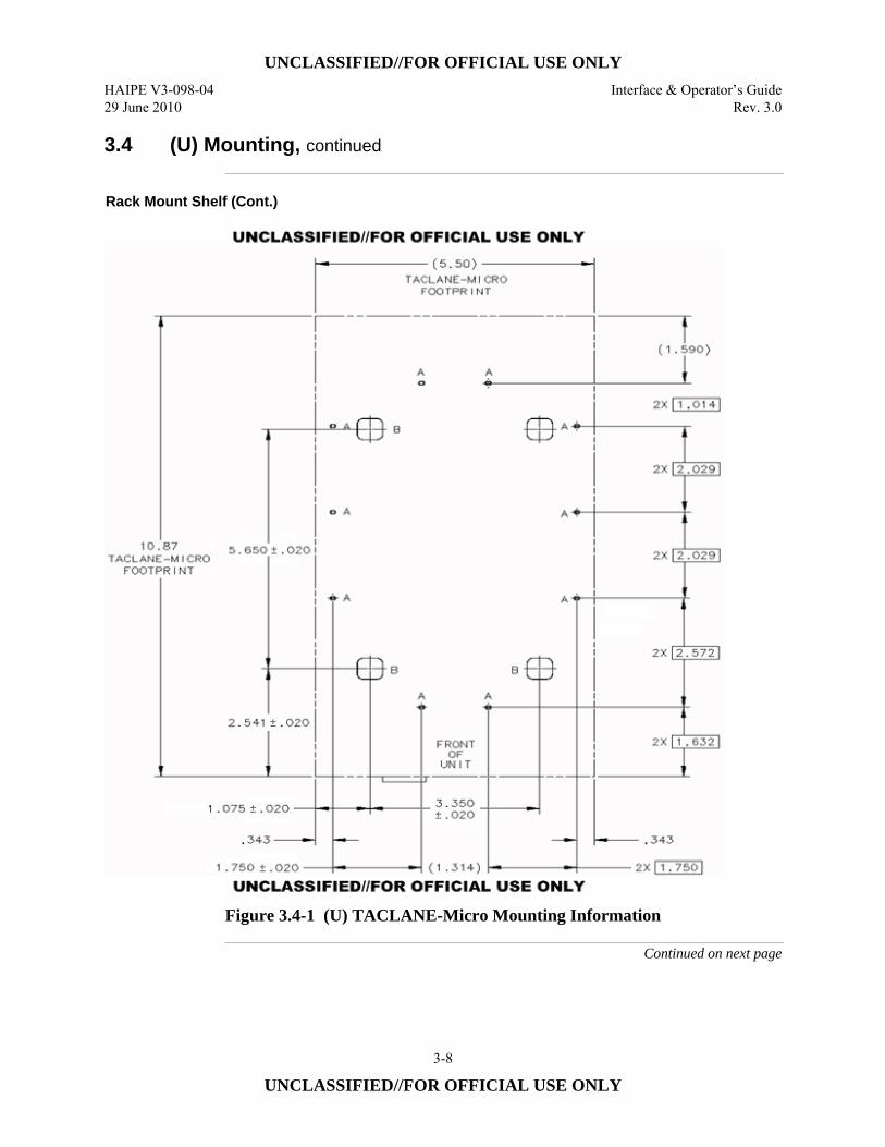
UNCLASSIFIED//FOR OFFICIAL USE ONLY HAIPE V3-098-04 Interface & Operator’s Guide 29 June 2010 Rev. 3.0
3-8
UNCLASSIFIED//FOR OFFICIAL USE ONLY
3.4 (U) Mounting, continued
Rack Mount Shelf (Cont.)
Figure 3.4-1 (U) TACLANE-Micro Mounting Information
Continued on next page
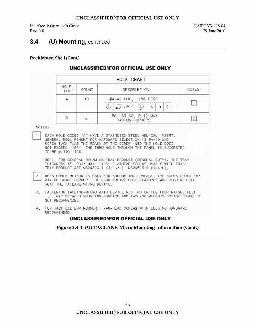
UNCLASSIFIED//FOR OFFICIAL USE ONLY Interface & Operator’s Guide HAIPE V3-098-04 Rev. 3.0 29 June 2010
3-9
UNCLASSIFIED//FOR OFFICIAL USE ONLY
3.4 (U) Mounting, continued
Rack Mount Shelf (Cont.)
Figure 3.4-1 (U) TACLANE-Micro Mounting Information (Cont.)
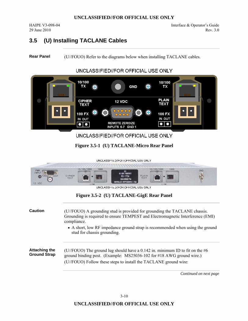
UNCLASSIFIED//FOR OFFICIAL USE ONLY HAIPE V3-098-04 Interface & Operator’s Guide 29 June 2010 Rev. 3.0
3-10
UNCLASSIFIED//FOR OFFICIAL USE ONLY
3.5 (U) Installing TACLANE Cables
Rear Panel (U//FOUO) Refer to the diagrams below when installing TACLANE cables.
Figure 3.5-1 (U) TACLANE-Micro Rear Panel
Figure 3.5-2 (U) TACLANE-GigE Rear Panel
Caution (U//FOUO) A grounding stud is provided for grounding the TACLANE chassis.
Grounding is required to ensure TEMPEST and Electromagnetic Interference (EMI) compliance. • A short, low RF impedance ground strap is recommended when using the ground
stud for chassis grounding.
Attaching the Ground Strap
(U//FOUO) The ground lug should have a 0.142 in. minimum ID to fit on the #6 ground binding post. (Example: MS25036-102 for #18 AWG ground wire.) (U//FOUO) Follow these steps to install the TACLANE ground wire:
Continued on next page
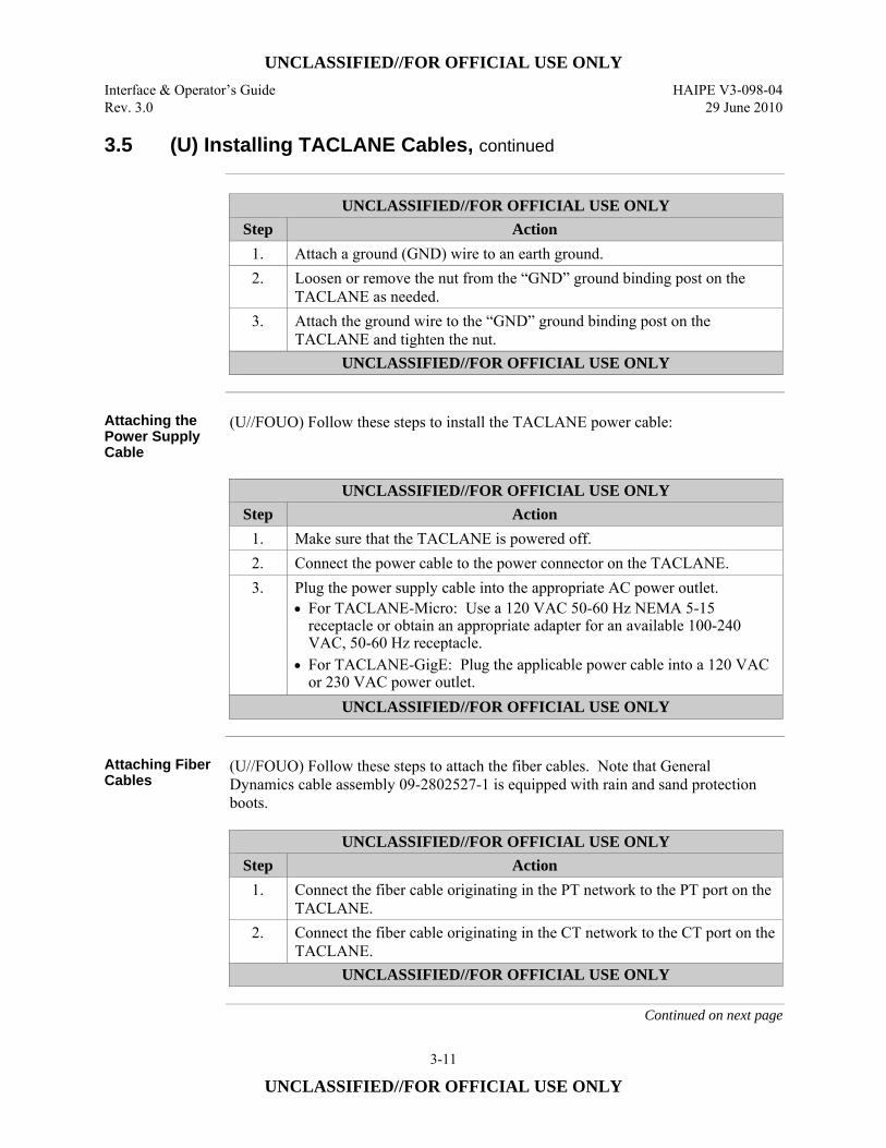
UNCLASSIFIED//FOR OFFICIAL USE ONLY Interface & Operator’s Guide HAIPE V3-098-04 Rev. 3.0 29 June 2010
3-11
UNCLASSIFIED//FOR OFFICIAL USE ONLY
3.5 (U) Installing TACLANE Cables, continued
UNCLASSIFIED//FOR OFFICIAL USE ONLY
Step Action 1. Attach a ground (GND) wire to an earth ground. 2. Loosen or remove the nut from the “GND” ground binding post on the
TACLANE as needed. 3. Attach the ground wire to the “GND” ground binding post on the
TACLANE and tighten the nut. UNCLASSIFIED//FOR OFFICIAL USE ONLY
Attaching the Power Supply Cable
(U//FOUO) Follow these steps to install the TACLANE power cable:
UNCLASSIFIED//FOR OFFICIAL USE ONLY
Step Action 1. Make sure that the TACLANE is powered off. 2. Connect the power cable to the power connector on the TACLANE. 3. Plug the power supply cable into the appropriate AC power outlet.
• For TACLANE-Micro: Use a 120 VAC 50-60 Hz NEMA 5-15 receptacle or obtain an appropriate adapter for an available 100-240 VAC, 50-60 Hz receptacle.
• For TACLANE-GigE: Plug the applicable power cable into a 120 VAC or 230 VAC power outlet.
UNCLASSIFIED//FOR OFFICIAL USE ONLY
Attaching Fiber Cables
(U//FOUO) Follow these steps to attach the fiber cables. Note that General Dynamics cable assembly 09-2802527-1 is equipped with rain and sand protection boots.
UNCLASSIFIED//FOR OFFICIAL USE ONLY
Step Action 1. Connect the fiber cable originating in the PT network to the PT port on the
TACLANE. 2. Connect the fiber cable originating in the CT network to the CT port on the
TACLANE. UNCLASSIFIED//FOR OFFICIAL USE ONLY
Continued on next page
UNCLASSIFIED//FOR OFFICIAL USE ONLY HAIPE V3-098-04 Interface & Operator’s Guide 29 June 2010 Rev. 3.0
3-12
UNCLASSIFIED//FOR OFFICIAL USE ONLY
3.5 (U) Installing TACLANE Cables, continued
Attaching a Twisted Pair Copper Ethernet Cable
(U//FOUO) Follow these steps to attach an STP copper Ethernet cable. Note that the IEEE recommended cable distance limit for Category 5 Unshielded Twisted Pair (UTP), Category 5e UTP, and Category 6 UTP is 328 ft. (100 m.). Note: For the TACLANE-GigE, 1000BASE-TX requires Category 5e or Category 6 cables.
UNCLASSIFIED//FOR OFFICIAL USE ONLY
Step Action 1. Connect the Ethernet cable originating in the PT network to the PT RJ-45
jack on the TACLANE. 2. Connect the Ethernet cable originating in the CT network to the CT RJ-45
jack on the TACLANE. UNCLASSIFIED//FOR OFFICIAL USE ONLY
Ethernet Cable Installation for TEMPEST/EMI Compliance
(U//FOUO) TEMPEST and EMI compliance requires use of double shielded signal cables. The PT and CT cables must be separated by a minimum of two (2) inches. For long cable lengths (greater than 10 feet), Shielded Foil Twisted Pair (SFTP) is preferred and the PT cable shall be routed such that it is separated by a minimum of six inches from the AC power cable. In addition, it is required that a ground strap shall be connected between the binding post on the rear of the chassis labeled “GND” and earth ground.
STP vs. UTP Ethernet Cable
(U//FOUO) TACLANE can be used with STP or UTP Ethernet cable. However, STP Ethernet cable is required in order to meet EMI/TEMPEST specifications.
Straight vs. Crossover Ethernet Cable
(U//FOUO) Each TACLANE Ethernet interface auto-senses whether the Ethernet cable is a crossover or straight through cable, so these cables can be used interchangeably.
Continued on next page
UNCLASSIFIED//FOR OFFICIAL USE ONLY Interface & Operator’s Guide HAIPE V3-098-04 Rev. 3.0 29 June 2010
3-13
UNCLASSIFIED//FOR OFFICIAL USE ONLY
3.5 (U) Installing TACLANE Cables, continued
Fiber Interface Characteristics
(U//FOUO) The following characteristics apply to the TACLANE-Micro 100Base-FX fiber interfaces: • 1300 nm short reach optics. • Duplex Lampert Connector (LC) fiber connectors.
(U//FOUO) The following characteristics apply to the TACLANE-GigE 1000Base-SX fiber interfaces: • Full compliance with the optical performance requirements of 1000Base-SX
version of IEEE 802.3z. • Transceivers can be used with 275 m. multimode fiber backbones. • Small Form-factor Pluggable (SFP) modules with LC fiber connectors.
(U//FOUO) The following characteristics apply to the optional TACLANE- GigE 1000Base-LX fiber interfaces: • Full compliance with the optical performance requirements of 1000Base-LX
version of IEEE 802.3z. • Transceivers can be used with 5000 m. single mode fiber backbones. • SFP modules with LC fiber connectors.
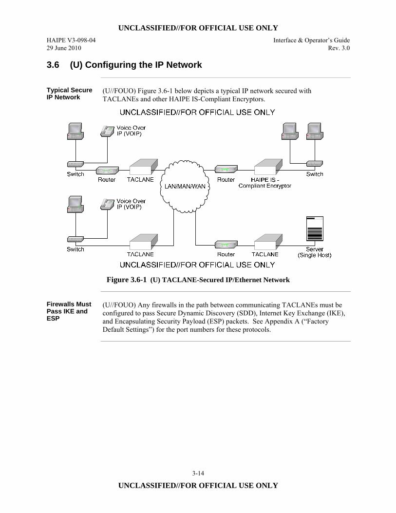
UNCLASSIFIED//FOR OFFICIAL USE ONLY HAIPE V3-098-04 Interface & Operator’s Guide 29 June 2010 Rev. 3.0
3-14
UNCLASSIFIED//FOR OFFICIAL USE ONLY
3.6 (U) Configuring the IP Network
Typical Secure IP Network
(U//FOUO) Figure 3.6-1 below depicts a typical IP network secured with TACLANEs and other HAIPE IS-Compliant Encryptors.
Figure 3.6-1 (U) TACLANE-Secured IP/Ethernet Network
Firewalls Must Pass IKE and ESP
(U//FOUO) Any firewalls in the path between communicating TACLANEs must be configured to pass Secure Dynamic Discovery (SDD), Internet Key Exchange (IKE), and Encapsulating Security Payload (ESP) packets. See Appendix A (“Factory Default Settings”) for the port numbers for these protocols.

UNCLASSIFIED//FOR OFFICIAL USE ONLY Interface & Operator’s Guide HAIPE V3-098-04 Rev. 3.0 29 June 2010
3-15
UNCLASSIFIED//FOR OFFICIAL USE ONLY
3.7 (U) Operating the TACLANE
TACLANE Front Panels
(U//FOUO) The TACLANE contains the Front Panel components shown in the figures below.
UNCLASSIFIED//FOR OFFICIAL USE ONLY
Figure 3.7-1 (U) TACLANE-Micro Front Panel
UNCLASSIFIED//FOR OFFICIAL USE ONLY
Figure 3.7-2 (U) TACLANE-GigE Front Panel
Continued on next page
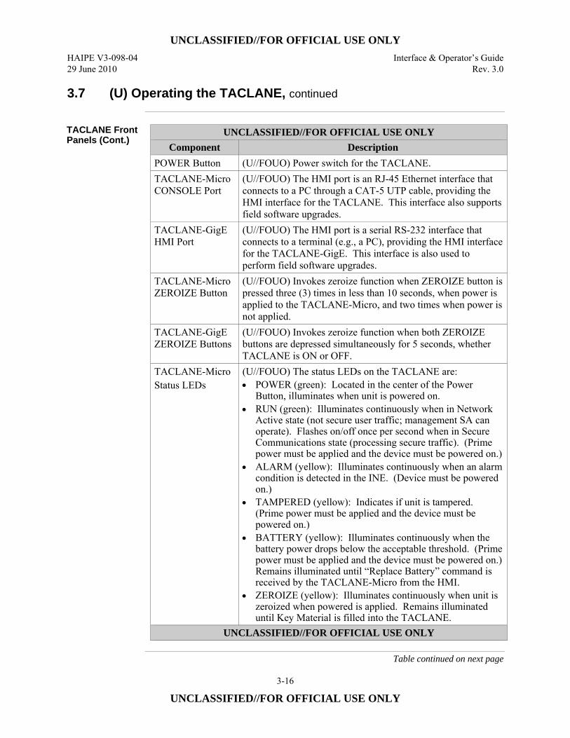
UNCLASSIFIED//FOR OFFICIAL USE ONLY HAIPE V3-098-04 Interface & Operator’s Guide 29 June 2010 Rev. 3.0
3-16
UNCLASSIFIED//FOR OFFICIAL USE ONLY
3.7 (U) Operating the TACLANE, continued
TACLANE Front Panels (Cont.)
UNCLASSIFIED//FOR OFFICIAL USE ONLY Component Description
POWER Button (U//FOUO) Power switch for the TACLANE. TACLANE-Micro CONSOLE Port
(U//FOUO) The HMI port is an RJ-45 Ethernet interface that connects to a PC through a CAT-5 UTP cable, providing the HMI interface for the TACLANE. This interface also supports field software upgrades.
TACLANE-GigE HMI Port
(U//FOUO) The HMI port is a serial RS-232 interface that connects to a terminal (e.g., a PC), providing the HMI interface for the TACLANE-GigE. This interface is also used to perform field software upgrades.
TACLANE-Micro ZEROIZE Button
(U//FOUO) Invokes zeroize function when ZEROIZE button is pressed three (3) times in less than 10 seconds, when power is applied to the TACLANE-Micro, and two times when power is not applied.
TACLANE-GigE ZEROIZE Buttons
(U//FOUO) Invokes zeroize function when both ZEROIZE buttons are depressed simultaneously for 5 seconds, whether TACLANE is ON or OFF.
TACLANE-Micro Status LEDs
(U//FOUO) The status LEDs on the TACLANE are: • POWER (green): Located in the center of the Power
Button, illuminates when unit is powered on. • RUN (green): Illuminates continuously when in Network
Active state (not secure user traffic; management SA can operate). Flashes on/off once per second when in Secure Communications state (processing secure traffic). (Prime power must be applied and the device must be powered on.)
• ALARM (yellow): Illuminates continuously when an alarm condition is detected in the INE. (Device must be powered on.)
• TAMPERED (yellow): Indicates if unit is tampered. (Prime power must be applied and the device must be powered on.)
• BATTERY (yellow): Illuminates continuously when the battery power drops below the acceptable threshold. (Prime power must be applied and the device must be powered on.) Remains illuminated until “Replace Battery” command is received by the TACLANE-Micro from the HMI.
• ZEROIZE (yellow): Illuminates continuously when unit is zeroized when powered is applied. Remains illuminated until Key Material is filled into the TACLANE.
UNCLASSIFIED//FOR OFFICIAL USE ONLY
Table continued on next page
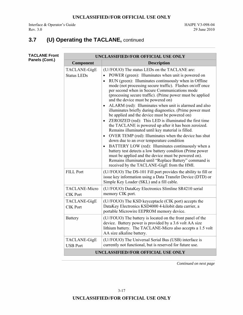
UNCLASSIFIED//FOR OFFICIAL USE ONLY Interface & Operator’s Guide HAIPE V3-098-04 Rev. 3.0 29 June 2010
3-17
UNCLASSIFIED//FOR OFFICIAL USE ONLY
3.7 (U) Operating the TACLANE, continued
TACLANE Front Panels (Cont.)
UNCLASSIFIED//FOR OFFICIAL USE ONLY Component Description
TACLANE-GigE Status LEDs
(U//FOUO) The status LEDs on the TACLANE are: • POWER (green): Illuminates when unit is powered on • RUN (green): Illuminates continuously when in Offline
mode (not processing secure traffic). Flashes on/off once per second when in Secure Communications mode (processing secure traffic). (Prime power must be applied and the device must be powered on)
• ALARM (red): Illuminates when unit is alarmed and also illuminates briefly during diagnostics. (Prime power must be applied and the device must be powered on)
• ZEROIZED (red): This LED is illuminated the first time the TACLANE is powered up after it has been zeroized. Remains illuminated until key material is filled.
• OVER TEMP (red): Illuminates when the device has shut down due to an over temperature condition
• BATTERY LOW (red): Illuminates continuously when a battery test detects a low battery condition (Prime power must be applied and the device must be powered on). Remains illuminated until “Replace Battery” command is received by the TACLANE-GigE from the HMI.
FILL Port (U//FOUO) The DS-101 Fill port provides the ability to fill or issue key information using a Data Transfer Device (DTD) or Simple Key Loader (SKL) and a fill cable.
TACLANE-Micro CIK Port
(U//FOUO) DataKey Electronics Slimline SR4210 serial memory CIK port.
TACLANE-GigE CIK Port
(U//FOUO) The KSD keyceptacle (CIK port) accepts the DataKey Electronics KSD4000 4-kilobit data carrier, a portable Microwire EEPROM memory device.
Battery (U//FOUO) The battery is located on the front panel of the device. Battery power is provided by a 3.6 volt AA size lithium battery. The TACLANE-Micro also accepts a 1.5 volt AA size alkaline battery.
TACLANE-GigE USB Port
(U//FOUO) The Universal Serial Bus (USB) interface is currently not functional, but is reserved for future use.
UNCLASSIFIED//FOR OFFICIAL USE ONLY
Continued on next page
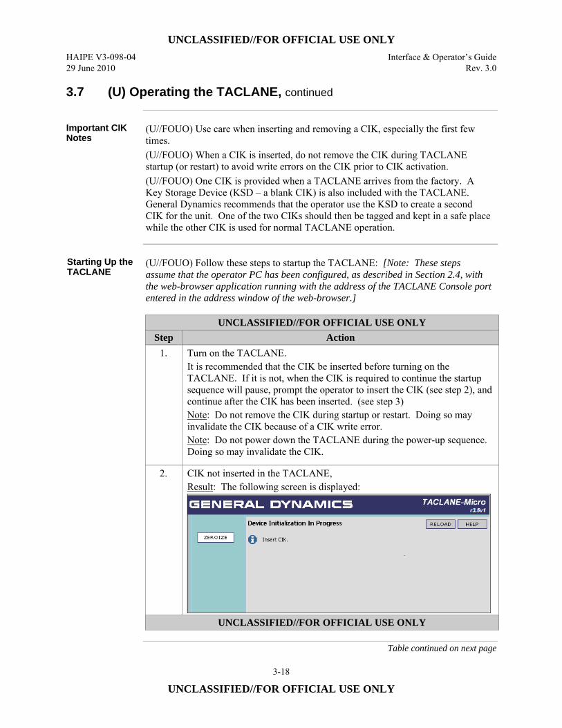
UNCLASSIFIED//FOR OFFICIAL USE ONLY HAIPE V3-098-04 Interface & Operator’s Guide 29 June 2010 Rev. 3.0
3-18
UNCLASSIFIED//FOR OFFICIAL USE ONLY
3.7 (U) Operating the TACLANE, continued
Important CIK Notes
(U//FOUO) Use care when inserting and removing a CIK, especially the first few times. (U//FOUO) When a CIK is inserted, do not remove the CIK during TACLANE startup (or restart) to avoid write errors on the CIK prior to CIK activation. (U//FOUO) One CIK is provided when a TACLANE arrives from the factory. A Key Storage Device (KSD – a blank CIK) is also included with the TACLANE. General Dynamics recommends that the operator use the KSD to create a second CIK for the unit. One of the two CIKs should then be tagged and kept in a safe place while the other CIK is used for normal TACLANE operation.
Starting Up the TACLANE
(U//FOUO) Follow these steps to startup the TACLANE: [Note: These steps assume that the operator PC has been configured, as described in Section 2.4, with the web-browser application running with the address of the TACLANE Console port entered in the address window of the web-browser.]
UNCLASSIFIED//FOR OFFICIAL USE ONLY
Step Action 1. Turn on the TACLANE.
It is recommended that the CIK be inserted before turning on the TACLANE. If it is not, when the CIK is required to continue the startup sequence will pause, prompt the operator to insert the CIK (see step 2), and continue after the CIK has been inserted. (see step 3) Note: Do not remove the CIK during startup or restart. Doing so may invalidate the CIK because of a CIK write error. Note: Do not power down the TACLANE during the power-up sequence. Doing so may invalidate the CIK.
2. CIK not inserted in the TACLANE, Result: The following screen is displayed:
UNCLASSIFIED//FOR OFFICIAL USE ONLY
Table continued on next page
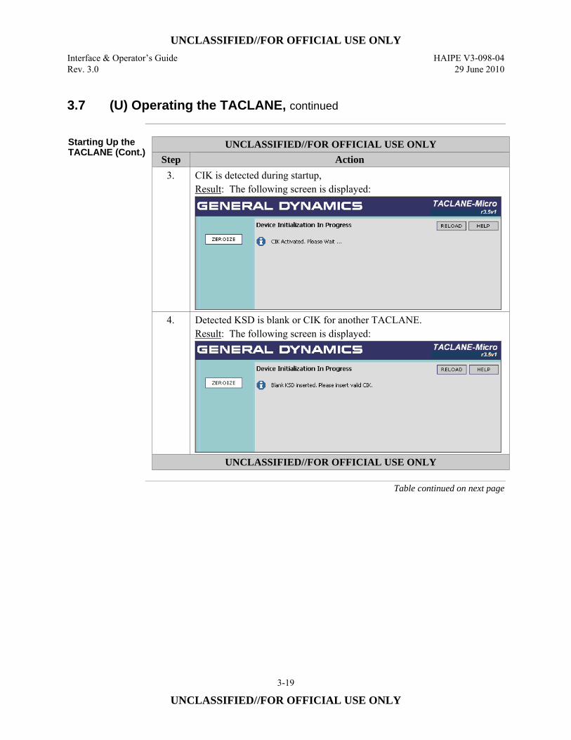
UNCLASSIFIED//FOR OFFICIAL USE ONLY Interface & Operator’s Guide HAIPE V3-098-04 Rev. 3.0 29 June 2010
3-19
UNCLASSIFIED//FOR OFFICIAL USE ONLY
3.7 (U) Operating the TACLANE, continued
Starting Up the TACLANE (Cont.)
UNCLASSIFIED//FOR OFFICIAL USE ONLY Step Action
3. CIK is detected during startup, Result: The following screen is displayed:
4. Detected KSD is blank or CIK for another TACLANE. Result: The following screen is displayed:
UNCLASSIFIED//FOR OFFICIAL USE ONLY
Table continued on next page
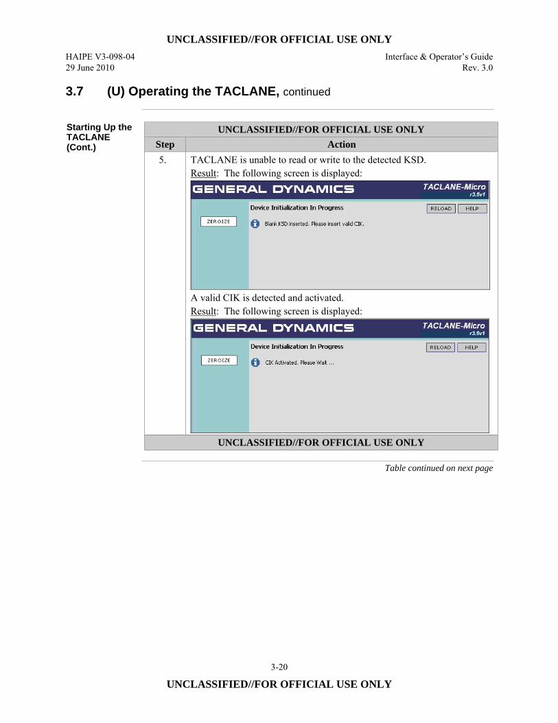
UNCLASSIFIED//FOR OFFICIAL USE ONLY HAIPE V3-098-04 Interface & Operator’s Guide 29 June 2010 Rev. 3.0
3-20
UNCLASSIFIED//FOR OFFICIAL USE ONLY
3.7 (U) Operating the TACLANE, continued
Starting Up the TACLANE (Cont.)
UNCLASSIFIED//FOR OFFICIAL USE ONLY Step Action 5. TACLANE is unable to read or write to the detected KSD.
Result: The following screen is displayed:
A valid CIK is detected and activated. Result: The following screen is displayed:
UNCLASSIFIED//FOR OFFICIAL USE ONLY
Table continued on next page
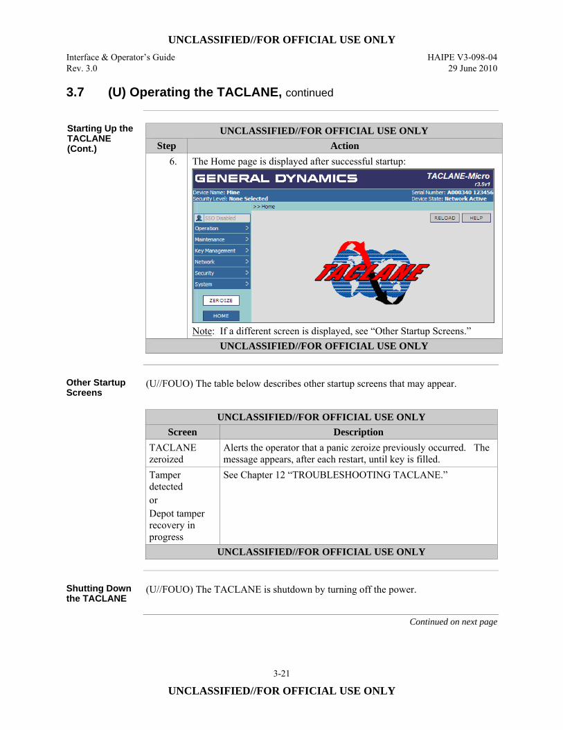
UNCLASSIFIED//FOR OFFICIAL USE ONLY Interface & Operator’s Guide HAIPE V3-098-04 Rev. 3.0 29 June 2010
3-21
UNCLASSIFIED//FOR OFFICIAL USE ONLY
3.7 (U) Operating the TACLANE, continued
Starting Up the TACLANE (Cont.)
UNCLASSIFIED//FOR OFFICIAL USE ONLY Step Action
6. The Home page is displayed after successful startup:
Note: If a different screen is displayed, see “Other Startup Screens.”
UNCLASSIFIED//FOR OFFICIAL USE ONLY
Other Startup Screens
(U//FOUO) The table below describes other startup screens that may appear.
UNCLASSIFIED//FOR OFFICIAL USE ONLY
Screen Description TACLANE zeroized
Alerts the operator that a panic zeroize previously occurred. The message appears, after each restart, until key is filled.
Tamper detected or Depot tamper recovery in progress
See Chapter 12 “TROUBLESHOOTING TACLANE.”
UNCLASSIFIED//FOR OFFICIAL USE ONLY
Shutting Down the TACLANE
(U//FOUO) The TACLANE is shutdown by turning off the power.
Continued on next page
UNCLASSIFIED//FOR OFFICIAL USE ONLY HAIPE V3-098-04 Interface & Operator’s Guide 29 June 2010 Rev. 3.0
3-22
UNCLASSIFIED//FOR OFFICIAL USE ONLY
3.7 (U) Operating the TACLANE, continued
Auto-recovery (U//FOUO) If the TACLANE is turned off or prime power fails while processing
user traffic, the TACLANE performs auto-recovery when power is restored, and automatically returns to the operational state it was in immediately preceding the shutdown: • Security associations reestablish automatically without operator intervention.
Clock Drift (U//FOUO) The TACLANE Real-Time-Clock is accurate to better than ±27.5
minutes per year under operating environmental conditions. TACLANE date and time should be checked for accuracy at least once every six months and adjusted if needed. See the chapter on “Maintaining TACLANE.”
3.8 (U) Features
TACLANE Features
(U//FOUO) TACLANE-Micro supports • IP datagram encryption over an Ethernet 10/100Base-TX or 100Base-FX
physical interface • 200 Mbps aggregate throughput, full duplex. • 512 Simultaneous bidirectional Security Associations (SAs) supported for user
traffic (one bidirectional Security Association protects all user traffic between a given pair of TACLANEs)
(U//FOUO) TACLANE-GigE supports • IP datagram encryption over an Ethernet 10/100/1000 Copper, 1000 Base-SX
(Multimode LC connector provided), or 1000 Base-LX (single mode LC connector available separately) physical interface
• 2 Gbps aggregate throughput, full duplex • 4096 Simultaneous bidirectional SAs
Continued on next page
UNCLASSIFIED//FOR OFFICIAL USE ONLY Interface & Operator’s Guide HAIPE V3-098-04 Rev. 3.0 29 June 2010
3-23
UNCLASSIFIED//FOR OFFICIAL USE ONLY
3.8 (U) Features, continued
TACLANE Features (Cont.)
(U//FOUO) Both TACLANE-Micro and TACLANE-GigE provide: • HAIPE IS v3.1.2 compliant IP encryption • Transport Mode security associations • Automated peer TACLANE discovery for security associations using Secure
Dynamic Discovery (SDD), Generic Discovery Client (GDC) and Implicit Peer Enclave Prefix Discovery (IM-PEPD)
• PPK or dynamically generated FIREFLY TEK for each security association • Enhanced FIREFLY (EFF) support • Up to 6 FFVS • Up to 48 traditional (traffic) and 72 exclusion key PPK chains to be used for user
traffic and SDD, with up to eleven changeover PPKs in each PPK chain • HAIPE-to-HAIPE Key Transfer In-Band and Out-of-Band • IP TFS controls: Fixed Packet Length, Payload Sequence Number (PSEQN)
Checking, Type-of-Service (Differentiated Services Code Point (DSCP)) Bypass, Don’t Fragment (DF) Bit bypass, Internet Group Management Protocol (IGMP) Bypass, Path Maximum Transmission Unit (PMTU) Bypass
• Security Policy Database • Security Association Database • Auto-Negotiating 10Base-T vs. 100Base-TX (vs. 1000Base-TX for GigE)
Ethernet interface • Static multicast with PPK • Remote TACLANE static routes • Over the Network Software Download and Field Software Upgrade • PACing and Privilege Commands • Over the Network update of Software Signature Parameters • Up to 12 simultaneous network managers.
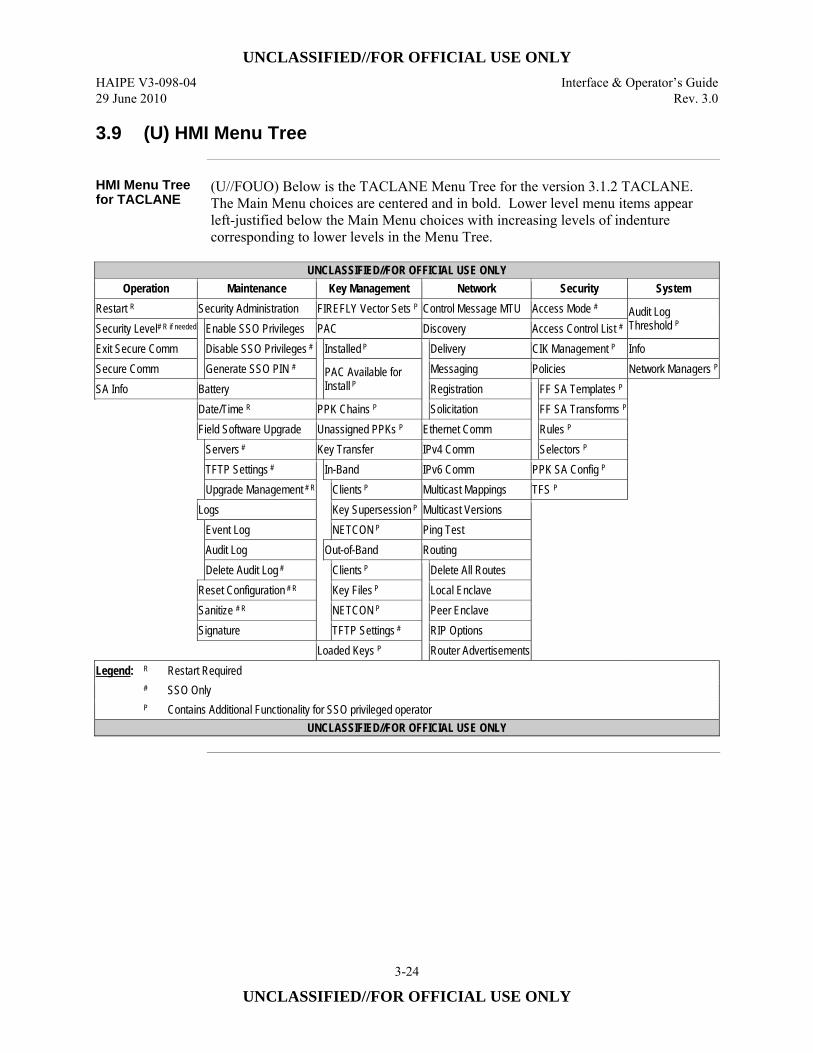
UNCLASSIFIED//FOR OFFICIAL USE ONLY HAIPE V3-098-04 Interface & Operator’s Guide 29 June 2010 Rev. 3.0
3-24
UNCLASSIFIED//FOR OFFICIAL USE ONLY
3.9 (U) HMI Menu Tree
HMI Menu Tree for TACLANE
(U//FOUO) Below is the TACLANE Menu Tree for the version 3.1.2 TACLANE. The Main Menu choices are centered and in bold. Lower level menu items appear left-justified below the Main Menu choices with increasing levels of indenture corresponding to lower levels in the Menu Tree.
UNCLASSIFIED//FOR OFFICIAL USE ONLY
Operation Maintenance Key Management Network Security System Restart R Security Administration FIREFLY Vector Sets P Control Message MTU Access Mode # Audit Log
Threshold P Security Level# R if needed
Enable SSO Privileges PAC Discovery Access Control List # Exit Secure Comm Disable SSO Privileges #
Installed P
Delivery CIK Management P Info Secure Comm Generate SSO PIN # PAC Available for
Install P Messaging Policies Network Managers P
SA Info Battery Registration
FF SA Templates P
Date/Time R PPK Chains P Solicitation FF SA Transforms P Field Software Upgrade Unassigned PPKs P Ethernet Comm Rules P
Servers # Key Transfer IPv4 Comm Selectors P TFTP Settings #
In-Band IPv6 Comm PPK SA Config P Upgrade Management # R
Clients P Multicast Mappings TFS P
Logs Key Supersession P Multicast Versions
Event Log NETCON P Ping Test Audit Log Out-of-Band Routing Delete Audit Log #
Clients P
Delete All Routes Reset Configuration # R Key Files P Local Enclave Sanitize # R NETCON P Peer Enclave Signature TFTP Settings # RIP Options Loaded Keys P Router Advertisements
Legend: R Restart Required # SSO Only P Contains Additional Functionality for SSO privileged operator
UNCLASSIFIED//FOR OFFICIAL USE ONLY
UNCLASSIFIED//FOR OFFICIAL USE ONLY Interface & Operator’s Guide HAIPE V3-098-04 Rev. 3.0 29 June 2010
4-1
UNCLASSIFIED//FOR OFFICIAL USE ONLY
4.0 (U) FILLING, ISSUING AND MANAGING KEYS
4.1 (U) Obtaining DTDs, SKLs, and Keys
DTD/SKL (U//FOUO) The Data Transfer Device (DTD) (AN/CYZ-10(V3)) and the Simple
Key Loader (SKL) can be used to fill TACLANEs with FIREFLY vector sets and PPKs. Operation of the SKL is similar to the DTD. This manual describes key issue and fill operations using a DTD. Refer to the SKL manual for specific directions for the SKL operation.
Obtaining DTDs and SKLs Through Military Supply
(U//FOUO) Obtaining DTDs through military supply: • Only available to Department of Defense (DoD) • National Stock Number (NSN) 5810-01-393-1973.
(U//FOUO) Obtaining SKLs through military supply: • Only available to Department of Defense (DoD) • National Stock Number (NSN) 7010-01-517-3587.
Note: (U//FOUO) U.S. Army personnel must order the AN/CYZ-10(V3) (and AN/PVQ-10(C)) through the Army Item Manager only. Call DSN 879-8176 or commercial (520) 538-8176 for additional information.
Non-DoD Procurement of SKLs – Contact Manufacturer
(U//FOUO) Contact Sierra Nevada Corporation, C4N Division, 444 Salomon Circle, Sparks, NV 89434. • Sierra Nevada Corporation will provide contact information for obtaining SKLs. • Sierra Nevada Corporate Phone Number: (775) 331-0222.
Continued on next page
UNCLASSIFIED//FOR OFFICIAL USE ONLY HAIPE V3-098-04 Interface & Operator’s Guide 29 June 2010 Rev. 3.0
4-2
UNCLASSIFIED//FOR OFFICIAL USE ONLY
4.1 (U) Obtaining DTDs, SKLs, and Keys, continued
Obtaining FIREFLY Vector Sets
(U//FOUO) Obtaining FIREFLY vector sets: • Coordinate with Controlling Authority for closed partitions (if needed). • Coordinate with COMSEC Account(s) to order and receive FIREFLY vector sets
(Secure Data Network System (SDNS) communications key) via EKMS and indicate:
– Order is for TACLANE device – Open or closed partition – Key Type of operational – Key Application of test or operational – Classifications. – Crypto Suite
Obtaining PPKs (U//FOUO) Obtaining PPKs:
• Coordinate with Controlling Authority for Short Title. • Coordinate with COMSEC Account(s) to order and receive traditional keys via
EKMS and indicate:
– Order is for TACLANE/FASTLANE-type traditional keys – Classification of traditional keys/cryptonet – Whether traditional keys are test or operational – Number of editions (crypto-period is one month) – Crypto Suite – In place and implementation date – Regular re-supply or as-needed – Short Title if reordering.
Key Use (U//FOUO) The FIREFLY vector set allows pair wise FIREFLY TEKs to be
dynamically set up between an initiator and responder TACLANE. PPKs are used to create security associations between an initiator and responder TACLANE.
UNCLASSIFIED//FOR OFFICIAL USE ONLY Interface & Operator’s Guide HAIPE V3-098-04 Rev. 3.0 29 June 2010
4-3
UNCLASSIFIED//FOR OFFICIAL USE ONLY
4.2 (U) Attaching a Fill Cable
Introduction (U//FOUO) A DTD, connected using a fill cable, is used to fill the TACLANE with
FIREFLY vector sets and/or PPKs. See the DTD User’s Manual for more information on DTD operation.
Note (U//FOUO) The fill cable is only needed when filling or issuing a key from a DTD.
The same procedure applies whether attaching the fill cable to the TACLANE (or equivalent) or the DTD – the cable connectors at each end are the same.
Procedure (U//FOUO) Follow these steps to attach the fill cable:
UNCLASSIFIED//FOR OFFICIAL USE ONLY Step Action
1. Line up the fill cable connector with the fill port so that the flat side of the connector is on top and centered on the red dot on the top of the fill port.
2. Apply firm pressure to press the cable connector toward the receptacle, and then slightly rotate the cable connector clockwise until it stops. Note: If the cable connector is difficult to attach, apply a small amount of silicone lubricant to the rubber O-ring inside the cable connector.
3. Remove pressure so the cable can set into locked position. Result: The fill cable is locked onto the fill port.
UNCLASSIFIED//FOR OFFICIAL USE ONLY
Procedure (U//FOUO) Follow these steps to remove the fill cable:
UNCLASSIFIED//FOR OFFICIAL USE ONLY Step Action
1. Apply firm pressure to press the cable connector toward the receptacle, and then slightly rotate the cable connector counter-clockwise until the flat side of the connector is on top.
2. Pull to remove the fill cable connector. Result: The fill cable is released from the fill port.
UNCLASSIFIED//FOR OFFICIAL USE ONLY
UNCLASSIFIED//FOR OFFICIAL USE ONLY HAIPE V3-098-04 Interface & Operator’s Guide 29 June 2010 Rev. 3.0
4-4
UNCLASSIFIED//FOR OFFICIAL USE ONLY
4.3 (U) Filling Keys (PPKs & FFVSs) from a DTD
Wake-up Signal (U//FOUO) The DTD needs to be configured to initiate a wake-up signal, or
equivalent, prior to filling key material to the TACLANE.
Initiate Fill (U//FOUO) In the TACLANE-Micro, one key or multiple keys can be filled during
one wake-up signal initiated session. When filling multiple keys from a DTD, there is a limit to the number of keys that can be filled in a given session. If filling keys takes longer than 5 minutes, the fill port will automatically be closed at the five-minute point, and those keys for which issue was not complete when the fill port closed will be ignored by the TACLANE. (U//FOUO) The TACLANE-GigE is restricted to filling a single key during one wake-up signal initiated session. (U//FOUO) There is no operator intervention needed at the TACLANE to fill key.
Multiple Security Levels
(U//FOUO) TACLANE does not allow multiple security level FFVS or PPKs to be filled.
Differing Key Material and TACLANE-GigE Operating Security Levels
(U//FOUO) The TACLANE-GigE will only accept filled key material equal to the security classification level to which it is configured. For example, filled SECRET key material will be rejected and zeroized, if the TACLANE-GigE is operating at a security classification level of: none, UNCLASSIFIED, CONFIDENTIAL, or TOP SECRET. (U//FOUO) This restriction does not apply to TACLANE-Micro.
Key Storage: FFVS
(U//FOUO) TACLANE allows a maximum of 6 current or current/next FIREFLY vector sets, each in a separate Universal ID. The TACLANE supports both the Enhanced FIREFLY (EFF) as well as the Basic FIREFLY.
Key Storage: PPKs
(U//FOUO) TACLANE allows a maximum of 1440 unassigned PPKs. A maximum of 1440 PPKs can be assigned to chains. TACLANE supports 48 traditional key chains and 72 Exclusion Key chains. Each key chain contains up to 12 keys; one active and 11 changeover keys.
Key Fill Indication
(U//FOUO) An Event Log entry is generated when a key is successfully filled into the TACLANE. A Security Audit Log entry is generated when a key is successfully or unsuccessfully filled into the TACLANE. If the key fill was successful, the type of key filled is indicated in the Security Audit Log record.
UNCLASSIFIED//FOR OFFICIAL USE ONLY Interface & Operator’s Guide HAIPE V3-098-04 Rev. 3.0 29 June 2010
4-5
UNCLASSIFIED//FOR OFFICIAL USE ONLY
4.4 (U) Issuing Keys (PPKs & FFVSs) from a DTD
Issued Keys (U//FOUO) Issued keys are EKMS-308 formatted key packages that have been
issued to the TACLANE from an external Out-of-Band-Key-Transfer NETCON, DTD or equivalent. They are stored in the Loaded Key Table and used by the HAIPE-to-HAIPE Key Transfer Function to be issued to another HAIPE device using Out-of-Band or filled to the same TACLANE or another HAIPE device using the In-Band Key Transfer function.
Wake-up Signal (U//FOUO) The DTD or SKL needs to be configured to initiate a wake-up signal, or
equivalent, prior to issuing key material to the TACLANE.
Initiate Issue (U//FOUO) In the TACLANE-Micro, one key or multiple keys can be issued to the
TACLANE during one wake-up signal initiated session. When a DTD or SKL is used to issue multiple keys, there is a limit to the number of keys that can be issued in a given session. If the issue takes longer than 5 minutes, the fill port will automatically be closed at the five-minute point, and those keys for which issue was not complete when the fill port closed will be ignored by the TACLANE. (U//FOUO) The TACLANE-GigE is restricted to receiving a single issued key during a wake-up signal initiated session. (U//FOUO) No operator intervention is needed at the TACLANE to issue keys.
Issued Key Storage
(U//FOUO) TACLANE allows a maximum of 30 keys to be stored in issue-format. It provides storage capacity for 24 PPKs and 6 FFVSs.
Key Fill Indication
(U//FOUO) Event Log and Security Audit Log entries are generated, when a key is successfully or unsuccessfully issued into the TACLANE. If a key issue is successful, the type of key issued is indicated in both the Security Audit Log and Event Log records.
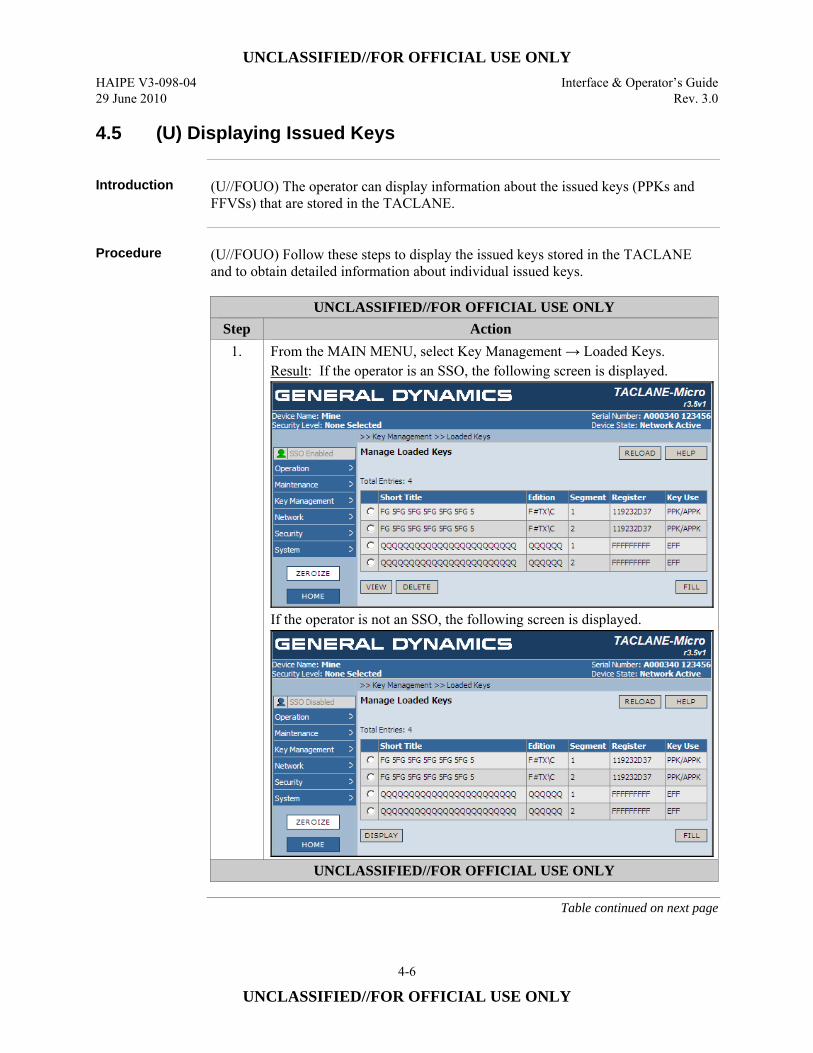
UNCLASSIFIED//FOR OFFICIAL USE ONLY HAIPE V3-098-04 Interface & Operator’s Guide 29 June 2010 Rev. 3.0
4-6
UNCLASSIFIED//FOR OFFICIAL USE ONLY
4.5 (U) Displaying Issued Keys
Introduction (U//FOUO) The operator can display information about the issued keys (PPKs and
FFVSs) that are stored in the TACLANE.
Procedure (U//FOUO) Follow these steps to display the issued keys stored in the TACLANE
and to obtain detailed information about individual issued keys.
UNCLASSIFIED//FOR OFFICIAL USE ONLY Step Action
1. From the MAIN MENU, select Key Management → Loaded Keys. Result: If the operator is an SSO, the following screen is displayed.
If the operator is not an SSO, the following screen is displayed.
UNCLASSIFIED//FOR OFFICIAL USE ONLY
Table continued on next page
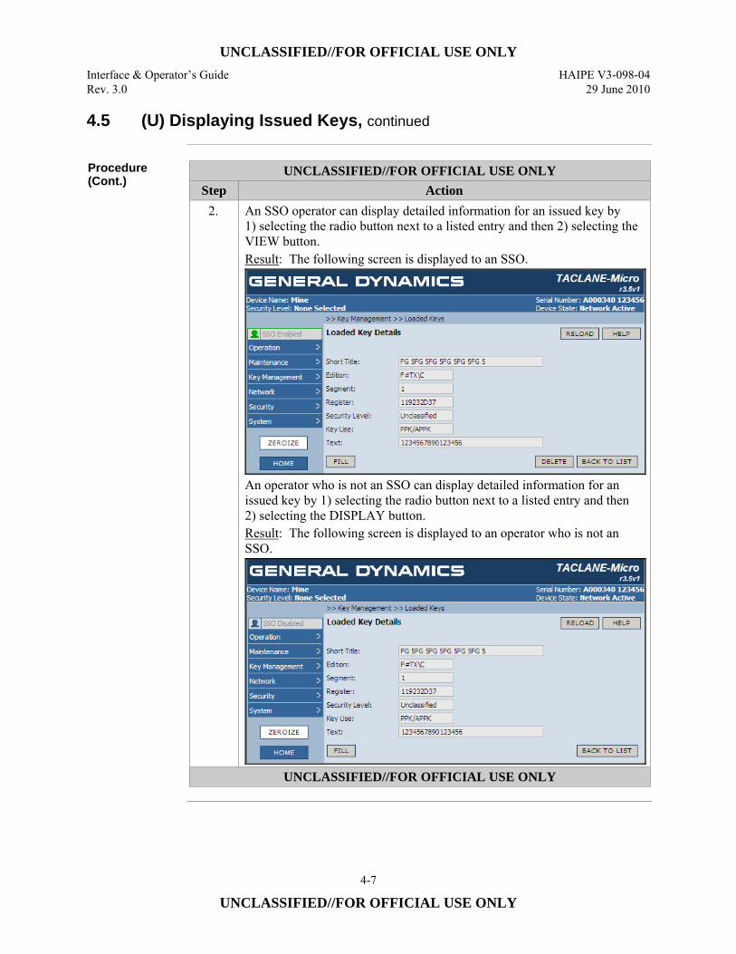
UNCLASSIFIED//FOR OFFICIAL USE ONLY Interface & Operator’s Guide HAIPE V3-098-04 Rev. 3.0 29 June 2010
4-7
UNCLASSIFIED//FOR OFFICIAL USE ONLY
4.5 (U) Displaying Issued Keys, continued
Procedure (Cont.)
UNCLASSIFIED//FOR OFFICIAL USE ONLY Step Action
2. An SSO operator can display detailed information for an issued key by 1) selecting the radio button next to a listed entry and then 2) selecting the VIEW button. Result: The following screen is displayed to an SSO.
An operator who is not an SSO can display detailed information for an issued key by 1) selecting the radio button next to a listed entry and then 2) selecting the DISPLAY button. Result: The following screen is displayed to an operator who is not an SSO.
UNCLASSIFIED//FOR OFFICIAL USE ONLY
UNCLASSIFIED//FOR OFFICIAL USE ONLY HAIPE V3-098-04 Interface & Operator’s Guide 29 June 2010 Rev. 3.0
4-8
UNCLASSIFIED//FOR OFFICIAL USE ONLY
4.6 (U) Filling Issued Keys
Introduction (U//FOUO) The operator can fill an issued key (i.e., a PPK or FFVS) that is stored in
the TACLANE.
Note (U//FOUO) If a PPK is filled from an issued PPK, the issued PPK remains in issued
key storage. (U//FOUO) If an FFVS is filled from an issued FFVS, the issued FFVS is automatically deleted from issued key storage. If the filled and deleted FFVS is currently included in an OOBKT NETCON Key File, future transfers of the key file to OOBKT Clients will be inhibited.
Key Fill Indications
(U//FOUO) Event Log and Security Audit Log entries are generated, when a key is successfully or unsuccessfully filled to the TACLANE from an issued key. If a key issue is successful, the type of key issued is indicated. (U//FOUO) If an FFVS is filled, Event and Security Audit Log entries are provided for FFVS deletion. (U//FOUO) If a filled and deleted FFVS is identified in a TACLANE OOBKT NETCON Key File, Event and Security Audit Log entries are provided for the deletion of a key that is listed in an OOBKT NETCON Key File.
Procedure (U//FOUO) Follow these steps to fill an issued key stored in the TACLANE.
Continued on next page
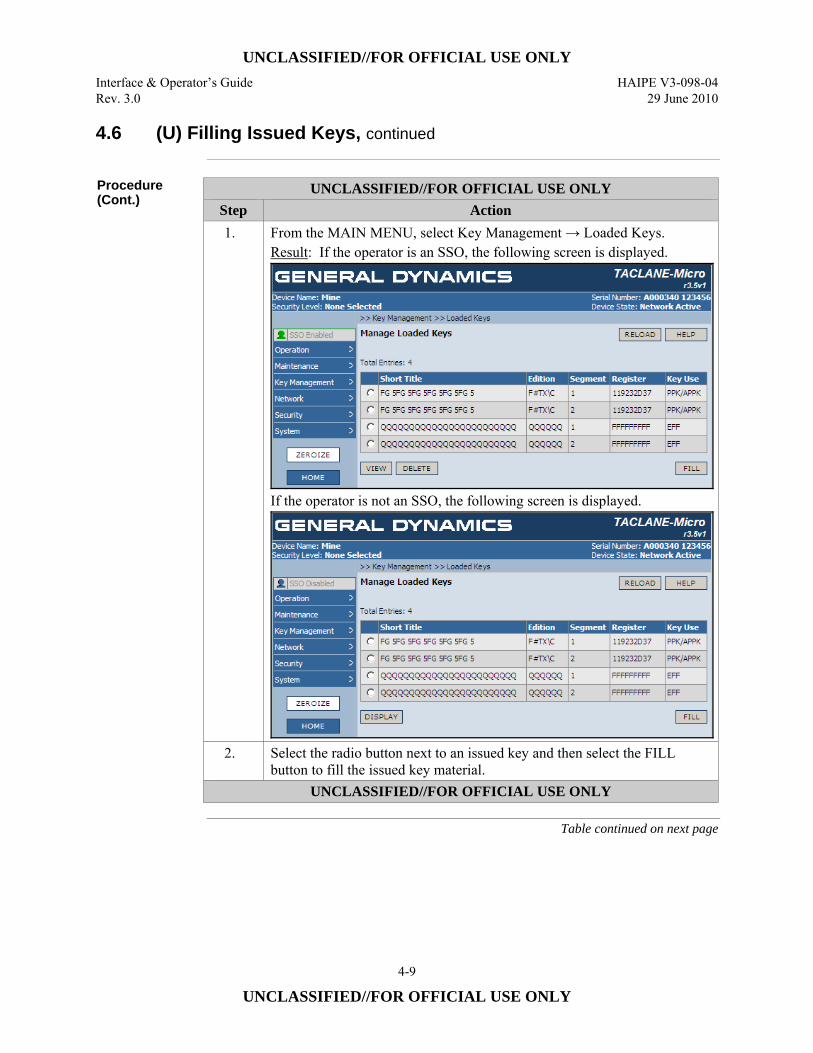
UNCLASSIFIED//FOR OFFICIAL USE ONLY Interface & Operator’s Guide HAIPE V3-098-04 Rev. 3.0 29 June 2010
4-9
UNCLASSIFIED//FOR OFFICIAL USE ONLY
4.6 (U) Filling Issued Keys, continued
Procedure (Cont.)
UNCLASSIFIED//FOR OFFICIAL USE ONLY Step Action 1. From the MAIN MENU, select Key Management → Loaded Keys.
Result: If the operator is an SSO, the following screen is displayed.
If the operator is not an SSO, the following screen is displayed.
2. Select the radio button next to an issued key and then select the FILL button to fill the issued key material.
UNCLASSIFIED//FOR OFFICIAL USE ONLY
Table continued on next page
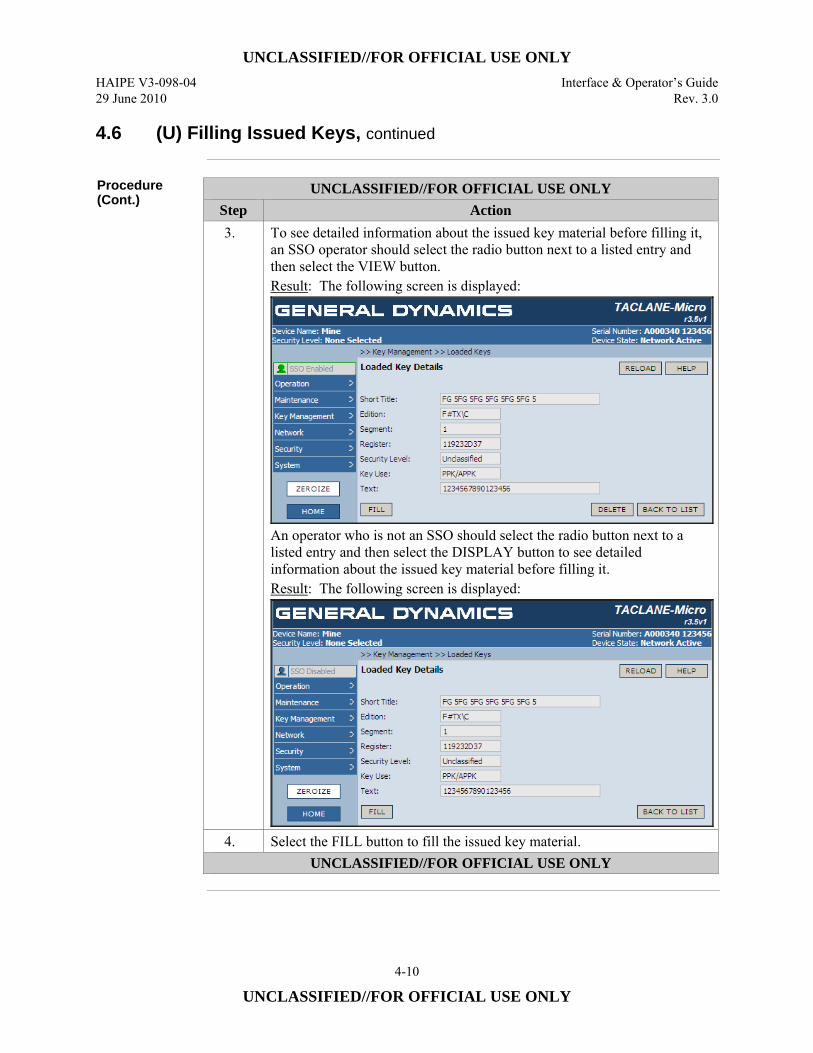
UNCLASSIFIED//FOR OFFICIAL USE ONLY HAIPE V3-098-04 Interface & Operator’s Guide 29 June 2010 Rev. 3.0
4-10
UNCLASSIFIED//FOR OFFICIAL USE ONLY
4.6 (U) Filling Issued Keys, continued
Procedure (Cont.)
UNCLASSIFIED//FOR OFFICIAL USE ONLY Step Action 3. To see detailed information about the issued key material before filling it,
an SSO operator should select the radio button next to a listed entry and then select the VIEW button. Result: The following screen is displayed:
An operator who is not an SSO should select the radio button next to a listed entry and then select the DISPLAY button to see detailed information about the issued key material before filling it. Result: The following screen is displayed:
4. Select the FILL button to fill the issued key material. UNCLASSIFIED//FOR OFFICIAL USE ONLY
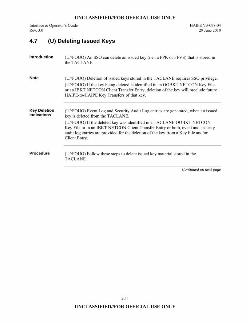
UNCLASSIFIED//FOR OFFICIAL USE ONLY Interface & Operator’s Guide HAIPE V3-098-04 Rev. 3.0 29 June 2010
4-11
UNCLASSIFIED//FOR OFFICIAL USE ONLY
4.7 (U) Deleting Issued Keys
Introduction (U//FOUO) An SSO can delete an issued key (i.e., a PPK or FFVS) that is stored in
the TACLANE.
Note (U//FOUO) Deletion of issued keys stored in the TACLANE requires SSO privilege.
(U//FOUO) If the key being deleted is identified in an OOBKT NETCON Key File or an IBKT NETCON Client Transfer Entry, deletion of the key will preclude future HAIPE-to-HAIPE Key Transfers of that key.
Key Deletion Indications
(U//FOUO) Event Log and Security Audit Log entries are generated, when an issued key is deleted from the TACLANE. (U//FOUO) If the deleted key was identified in a TACLANE OOBKT NETCON Key File or in an IBKT NETCON Client Transfer Entry or both, event and security audit log entries are provided for the deletion of the key from a Key File and/or Client Entry.
Procedure (U//FOUO) Follow these steps to delete issued key material stored in the
TACLANE.
Continued on next page
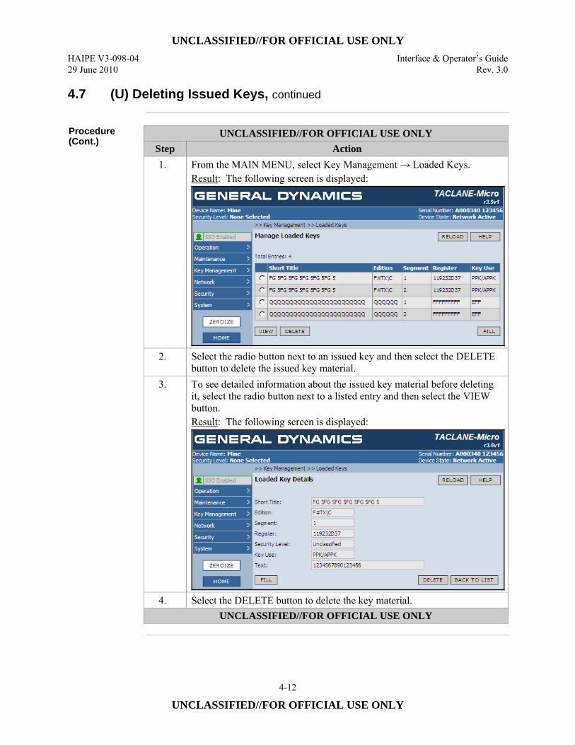
UNCLASSIFIED//FOR OFFICIAL USE ONLY HAIPE V3-098-04 Interface & Operator’s Guide 29 June 2010 Rev. 3.0
4-12
UNCLASSIFIED//FOR OFFICIAL USE ONLY
4.7 (U) Deleting Issued Keys, continued
Procedure (Cont.)
UNCLASSIFIED//FOR OFFICIAL USE ONLY Step Action 1. From the MAIN MENU, select Key Management → Loaded Keys.
Result: The following screen is displayed:
2. Select the radio button next to an issued key and then select the DELETE button to delete the issued key material.
3. To see detailed information about the issued key material before deleting it, select the radio button next to a listed entry and then select the VIEW button. Result: The following screen is displayed:
4. Select the DELETE button to delete the key material. UNCLASSIFIED//FOR OFFICIAL USE ONLY
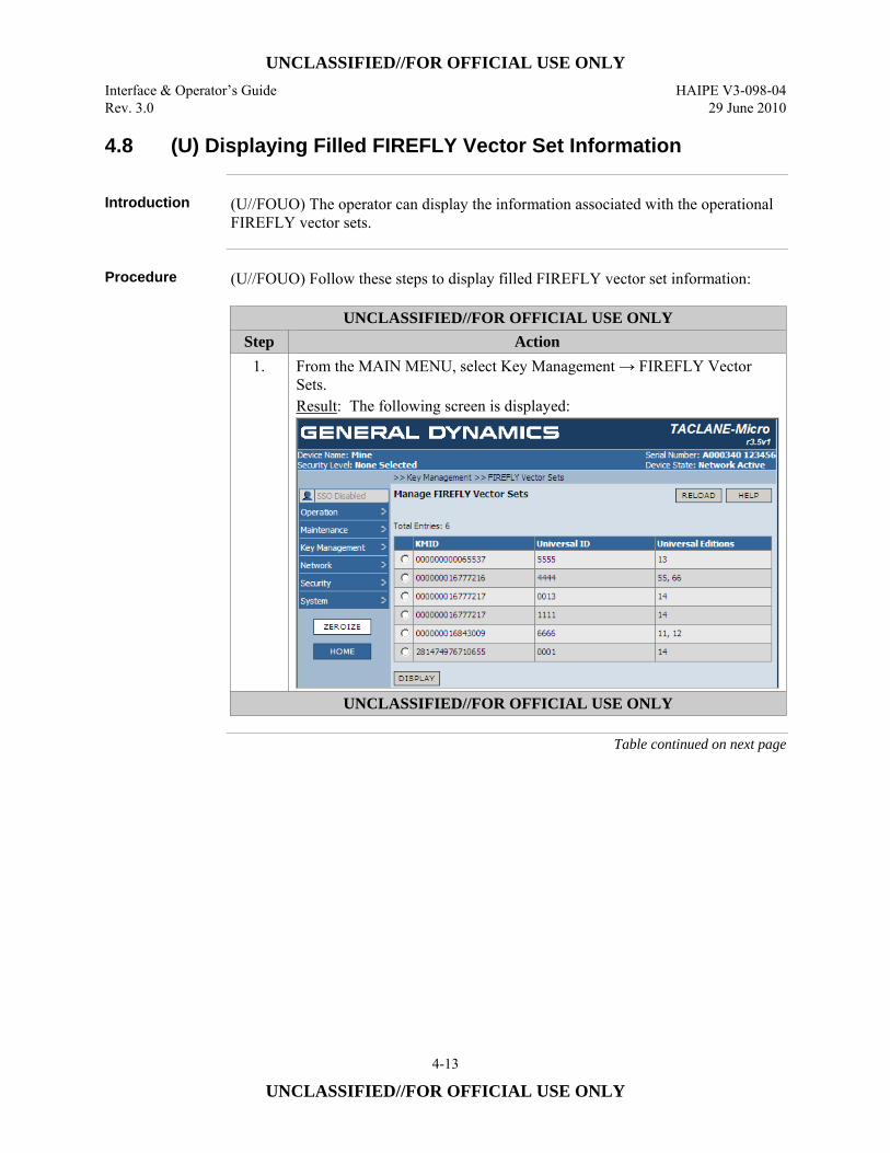
UNCLASSIFIED//FOR OFFICIAL USE ONLY Interface & Operator’s Guide HAIPE V3-098-04 Rev. 3.0 29 June 2010
4-13
UNCLASSIFIED//FOR OFFICIAL USE ONLY
4.8 (U) Displaying Filled FIREFLY Vector Set Information
Introduction (U//FOUO) The operator can display the information associated with the operational
FIREFLY vector sets.
Procedure (U//FOUO) Follow these steps to display filled FIREFLY vector set information:
UNCLASSIFIED//FOR OFFICIAL USE ONLY Step Action
1. From the MAIN MENU, select Key Management → FIREFLY Vector Sets. Result: The following screen is displayed:
UNCLASSIFIED//FOR OFFICIAL USE ONLY
Table continued on next page
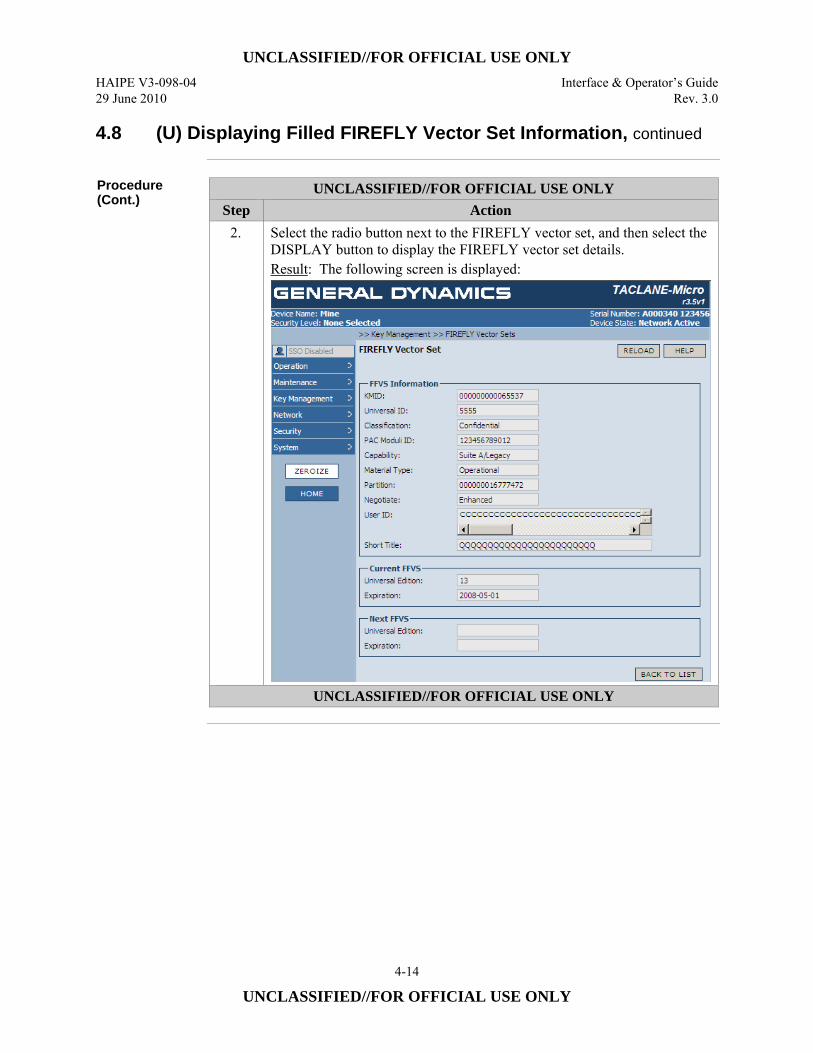
UNCLASSIFIED//FOR OFFICIAL USE ONLY HAIPE V3-098-04 Interface & Operator’s Guide 29 June 2010 Rev. 3.0
4-14
UNCLASSIFIED//FOR OFFICIAL USE ONLY
4.8 (U) Displaying Filled FIREFLY Vector Set Information, continued
Procedure (Cont.)
UNCLASSIFIED//FOR OFFICIAL USE ONLY Step Action
2. Select the radio button next to the FIREFLY vector set, and then select the DISPLAY button to display the FIREFLY vector set details. Result: The following screen is displayed:
UNCLASSIFIED//FOR OFFICIAL USE ONLY
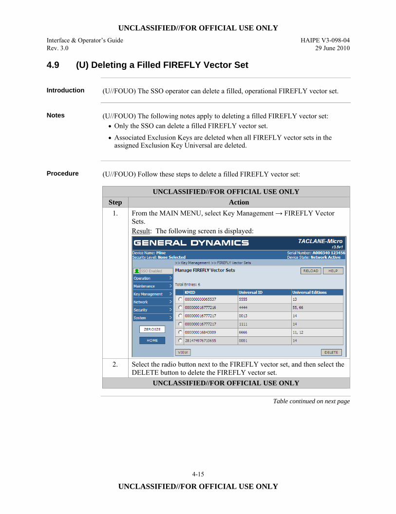
UNCLASSIFIED//FOR OFFICIAL USE ONLY Interface & Operator’s Guide HAIPE V3-098-04 Rev. 3.0 29 June 2010
4-15
UNCLASSIFIED//FOR OFFICIAL USE ONLY
4.9 (U) Deleting a Filled FIREFLY Vector Set
Introduction (U//FOUO) The SSO operator can delete a filled, operational FIREFLY vector set.
Notes (U//FOUO) The following notes apply to deleting a filled FIREFLY vector set:
• Only the SSO can delete a filled FIREFLY vector set. • Associated Exclusion Keys are deleted when all FIREFLY vector sets in the
assigned Exclusion Key Universal are deleted.
Procedure (U//FOUO) Follow these steps to delete a filled FIREFLY vector set:
UNCLASSIFIED//FOR OFFICIAL USE ONLY Step Action
1. From the MAIN MENU, select Key Management → FIREFLY Vector Sets. Result: The following screen is displayed:
2. Select the radio button next to the FIREFLY vector set, and then select the DELETE button to delete the FIREFLY vector set.
UNCLASSIFIED//FOR OFFICIAL USE ONLY
Table continued on next page
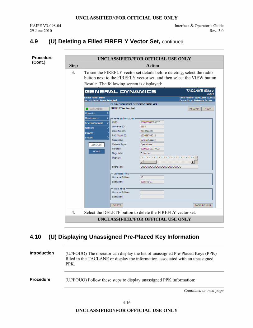
UNCLASSIFIED//FOR OFFICIAL USE ONLY HAIPE V3-098-04 Interface & Operator’s Guide 29 June 2010 Rev. 3.0
4-16
UNCLASSIFIED//FOR OFFICIAL USE ONLY
4.9 (U) Deleting a Filled FIREFLY Vector Set, continued
Procedure (Cont.)
UNCLASSIFIED//FOR OFFICIAL USE ONLY Step Action
3. To see the FIREFLY vector set details before deleting, select the radio button next to the FIREFLY vector set, and then select the VIEW button. Result: The following screen is displayed:
4. Select the DELETE button to delete the FIREFLY vector set. UNCLASSIFIED//FOR OFFICIAL USE ONLY
4.10 (U) Displaying Unassigned Pre-Placed Key Information
Introduction (U//FOUO) The operator can display the list of unassigned Pre-Placed Keys (PPK)
filled in the TACLANE or display the information associated with an unassigned PPK.
Procedure (U//FOUO) Follow these steps to display unassigned PPK information:
Continued on next page
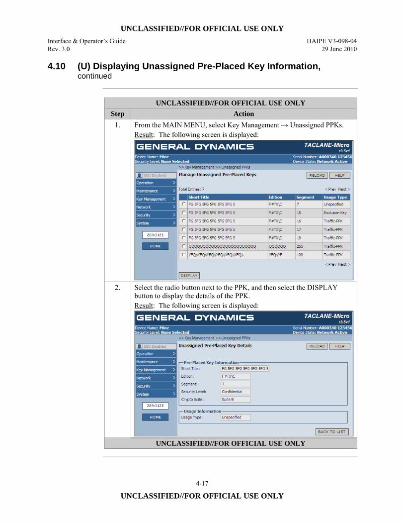
UNCLASSIFIED//FOR OFFICIAL USE ONLY Interface & Operator’s Guide HAIPE V3-098-04 Rev. 3.0 29 June 2010
4-17
UNCLASSIFIED//FOR OFFICIAL USE ONLY
4.10 (U) Displaying Unassigned Pre-Placed Key Information, continued
UNCLASSIFIED//FOR OFFICIAL USE ONLY
Step Action 1. From the MAIN MENU, select Key Management → Unassigned PPKs.
Result: The following screen is displayed:
2. Select the radio button next to the PPK, and then select the DISPLAY button to display the details of the PPK. Result: The following screen is displayed:
UNCLASSIFIED//FOR OFFICIAL USE ONLY
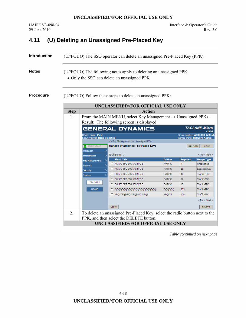
UNCLASSIFIED//FOR OFFICIAL USE ONLY HAIPE V3-098-04 Interface & Operator’s Guide 29 June 2010 Rev. 3.0
4-18
UNCLASSIFIED//FOR OFFICIAL USE ONLY
4.11 (U) Deleting an Unassigned Pre-Placed Key
Introduction (U//FOUO) The SSO operator can delete an unassigned Pre-Placed Key (PPK).
Notes (U//FOUO) The following notes apply to deleting an unassigned PPK:
• Only the SSO can delete an unassigned PPK
Procedure (U//FOUO) Follow these steps to delete an unassigned PPK:
UNCLASSIFIED//FOR OFFICIAL USE ONLY Step Action
1. From the MAIN MENU, select Key Management → Unassigned PPKs. Result: The following screen is displayed:
2. To delete an unassigned Pre-Placed Key, select the radio button next to the PPK, and then select the DELETE button.
UNCLASSIFIED//FOR OFFICIAL USE ONLY
Table continued on next page
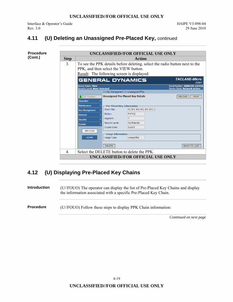
UNCLASSIFIED//FOR OFFICIAL USE ONLY Interface & Operator’s Guide HAIPE V3-098-04 Rev. 3.0 29 June 2010
4-19
UNCLASSIFIED//FOR OFFICIAL USE ONLY
4.11 (U) Deleting an Unassigned Pre-Placed Key, continued
Procedure (Cont.)
UNCLASSIFIED//FOR OFFICIAL USE ONLY Step Action
3. To see the PPK details before deleting, select the radio button next to the PPK, and then select the VIEW button. Result: The following screen is displayed:
4. Select the DELETE button to delete the PPK. UNCLASSIFIED//FOR OFFICIAL USE ONLY
4.12 (U) Displaying Pre-Placed Key Chains
Introduction (U//FOUO) The operator can display the list of Pre-Placed Key Chains and display
the information associated with a specific Pre-Placed Key Chain.
Procedure (U//FOUO) Follow these steps to display PPK Chain information:
Continued on next page
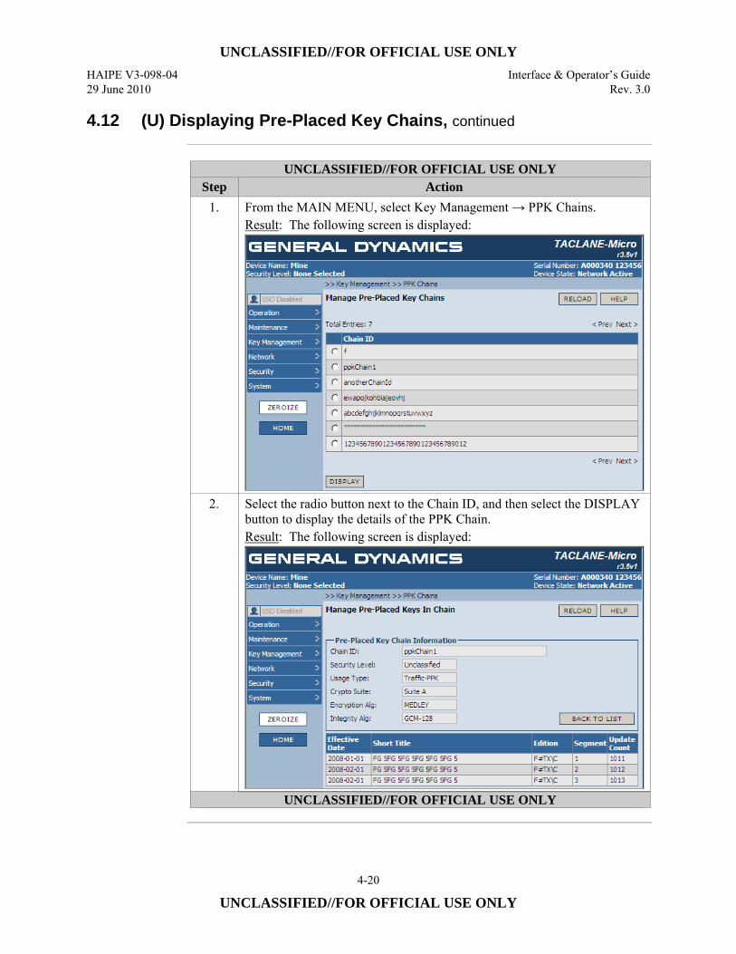
UNCLASSIFIED//FOR OFFICIAL USE ONLY HAIPE V3-098-04 Interface & Operator’s Guide 29 June 2010 Rev. 3.0
4-20
UNCLASSIFIED//FOR OFFICIAL USE ONLY
4.12 (U) Displaying Pre-Placed Key Chains, continued
UNCLASSIFIED//FOR OFFICIAL USE ONLY
Step Action 1. From the MAIN MENU, select Key Management → PPK Chains.
Result: The following screen is displayed:
2. Select the radio button next to the Chain ID, and then select the DISPLAY button to display the details of the PPK Chain. Result: The following screen is displayed:
UNCLASSIFIED//FOR OFFICIAL USE ONLY
UNCLASSIFIED//FOR OFFICIAL USE ONLY Interface & Operator’s Guide HAIPE V3-098-04 Rev. 3.0 29 June 2010
4-21
UNCLASSIFIED//FOR OFFICIAL USE ONLY
4.13 (U) Creating a Pre-Placed Key Chain
Introduction (U//FOUO) The SSO operator can create a Pre-Placed Key (PPK) Chain.
Notes (U//FOUO) The following notes apply to creating a PPK Chain:
• (U//FOUO) Only the SSO can create a PPK Chain • (U//FOUO) Only an unassigned PPK can be selected to create a chain • (U//FOUO) A total of 120 PPK chains may be assigned in a TACLANE. 48
chains can be used as Traffic key chains and 72 can be used as Exclusion Key chains. A PPK chain consists of the one active PPK and up to 11 changeover PPKs. During normal operation each PPK has a 1-month crypto-period; the 11 changeover PPKs allow an operator to only have to fill the PPKs once per year.
• (U//FOUO) All 120 PPK chains may be filled at one security level or several PPK chains may be filled at different security levels (up to a total of 120 PPK chains). As an example, one PPK chain may be created at the UNCLASSIFIED level, and another PPK chain may be created at the SECRET level.
• (U//FOUO) There are two uses of PPKs: Traffic PPKs and Exclusion Key (EK) PPKs.
• (U//FOUO) When creating a PPK Chain, the operator is prompted to enter the Chain ID, Security Level, Usage Type, and Crypto Suite for the Chain. If the Usage Type is Exclusion Key, the operator enters Exclusion Type and Universal ID. If the Usage Type is Traffic-PPK, the operator enters Encryption Algorithm
• (U//FOUO) The Effective Date of the PPK is entered by the operator. Any month and year for which the first of that month is no more than 1023 days in the past, and no more than 11 months in the future is valid when creating a chain. The day is automatically set to the first of the month (01).
• (U//FOUO) For proper operation within a cryptonet using PPKs, all TACLANEs in the cryptonet must have the PPK configured with the same effective date, use, and algorithm.
Continued on next page
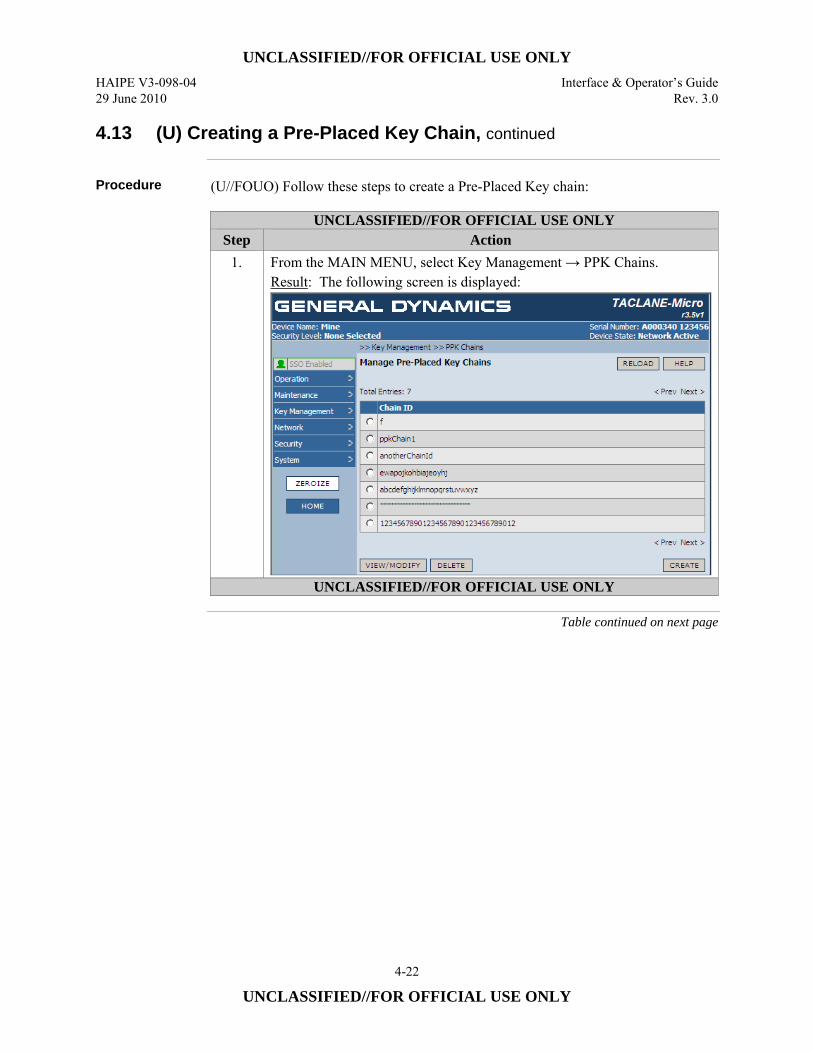
UNCLASSIFIED//FOR OFFICIAL USE ONLY HAIPE V3-098-04 Interface & Operator’s Guide 29 June 2010 Rev. 3.0
4-22
UNCLASSIFIED//FOR OFFICIAL USE ONLY
4.13 (U) Creating a Pre-Placed Key Chain, continued
Procedure (U//FOUO) Follow these steps to create a Pre-Placed Key chain:
UNCLASSIFIED//FOR OFFICIAL USE ONLY Step Action
1. From the MAIN MENU, select Key Management → PPK Chains. Result: The following screen is displayed:
UNCLASSIFIED//FOR OFFICIAL USE ONLY
Table continued on next page
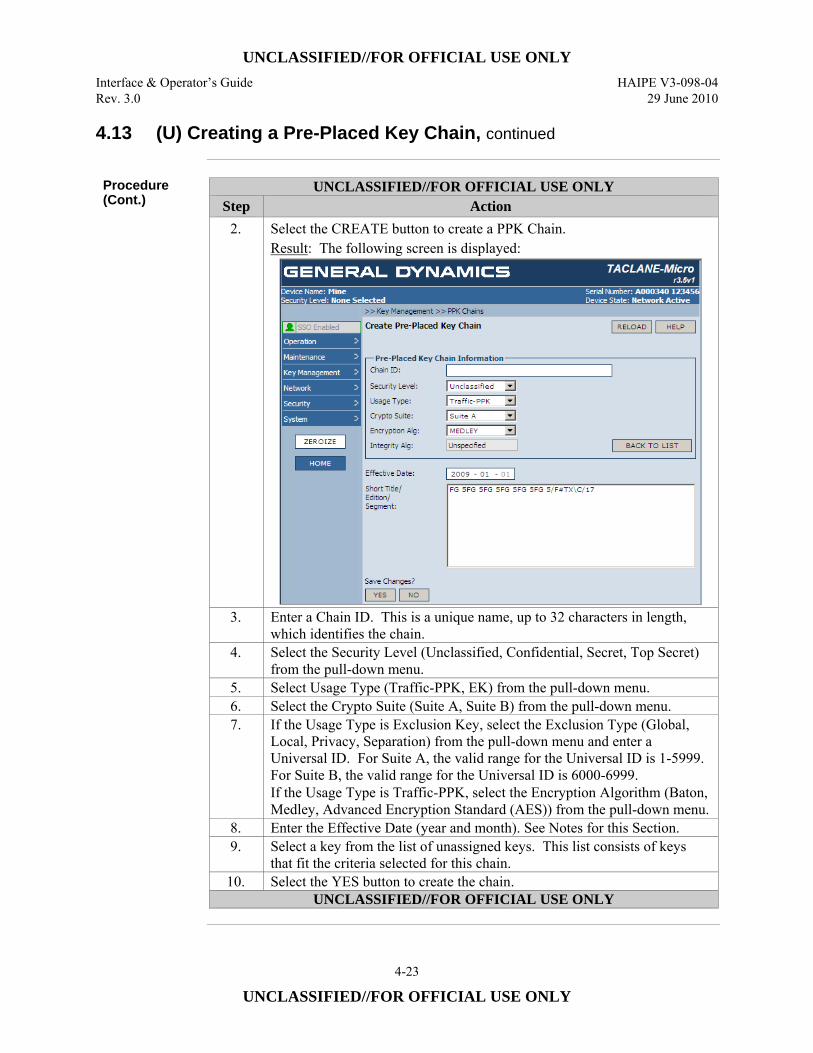
UNCLASSIFIED//FOR OFFICIAL USE ONLY Interface & Operator’s Guide HAIPE V3-098-04 Rev. 3.0 29 June 2010
4-23
UNCLASSIFIED//FOR OFFICIAL USE ONLY
4.13 (U) Creating a Pre-Placed Key Chain, continued
Procedure (Cont.)
UNCLASSIFIED//FOR OFFICIAL USE ONLY Step Action
2. Select the CREATE button to create a PPK Chain. Result: The following screen is displayed:
3. Enter a Chain ID. This is a unique name, up to 32 characters in length, which identifies the chain.
4. Select the Security Level (Unclassified, Confidential, Secret, Top Secret) from the pull-down menu.
5. Select Usage Type (Traffic-PPK, EK) from the pull-down menu. 6. Select the Crypto Suite (Suite A, Suite B) from the pull-down menu. 7. If the Usage Type is Exclusion Key, select the Exclusion Type (Global,
Local, Privacy, Separation) from the pull-down menu and enter a Universal ID. For Suite A, the valid range for the Universal ID is 1-5999. For Suite B, the valid range for the Universal ID is 6000-6999. If the Usage Type is Traffic-PPK, select the Encryption Algorithm (Baton, Medley, Advanced Encryption Standard (AES)) from the pull-down menu.
8. Enter the Effective Date (year and month). See Notes for this Section. 9. Select a key from the list of unassigned keys. This list consists of keys
that fit the criteria selected for this chain. 10. Select the YES button to create the chain.
UNCLASSIFIED//FOR OFFICIAL USE ONLY
UNCLASSIFIED//FOR OFFICIAL USE ONLY HAIPE V3-098-04 Interface & Operator’s Guide 29 June 2010 Rev. 3.0
4-24
UNCLASSIFIED//FOR OFFICIAL USE ONLY
4.14 (U) Assigning a Pre-Placed Key to an Existing Chain
Introduction (U//FOUO) The SSO operator can assign an unassigned Pre-Placed Key (PPK) to a
chain.
Notes (U//FOUO) The following notes apply to assigning an unassigned PPK:
• (U//FOUO) Only the SSO can assign a PPK • (U//FOUO) A PPK can only be assigned to one chain. • (U//FOUO) Only PPKs that are not assigned to a chain can be assigned to a
chain. • (U//FOUO) A PPK chain consists of the one active PPK and up to 11
changeover PPKs. During normal operation each PPK has a 1-month crypto-period, the 11 changeover PPKs allow an operator to only have to fill the PPKs once per year.
• (U//FOUO) When assigning a PPK to a chain, the operator is prompted to enter the Effective Date of the PPK. The month and year must be for the current month of the System Date to which the TACLANE is set, or one month in the future.
• Parameters other than Effective Date are inherited from the chain. • (U//FOUO) For proper operation within a cryptonet using PPKs, all TACLANEs
in the cryptonet must have the PPK configured with the same effective date, use, and algorithm.
(U//FOUO) PPKs may also be assigned to a key chain as a result of In-Band Key Transfer (IBKT). When this occurs, the effective date of the PPK is set by the IBKT Network Controller (NETCON). PPK assignments to key chains resulting from IBKT are automatic and require no operator involvement.
PPK Tag Format Supported
(U//FOUO) The TACLANE supports the DS-100-1 data tagging format for PPKs.
PPK Changeover
(U//FOUO) TACLANE PPK changeover (occurs on the first day every month as defined by the effective date) is centered at 00:00 GMT (midnight) with a plus or minus 55 minute window (to allow for clock drift) that starts at 23:05 GMT and ends at 00:55 GMT. (U//FOUO) For a security association, a TACLANE starts using the changeover PPK to encrypt user traffic at 00:00 GMT. A TACLANE is able to decrypt user traffic using either the current or changeover PPK within the window (23:05 GMT – 00:55 GMT). At the end of the window, the current PPK is deleted.
Continued on next page
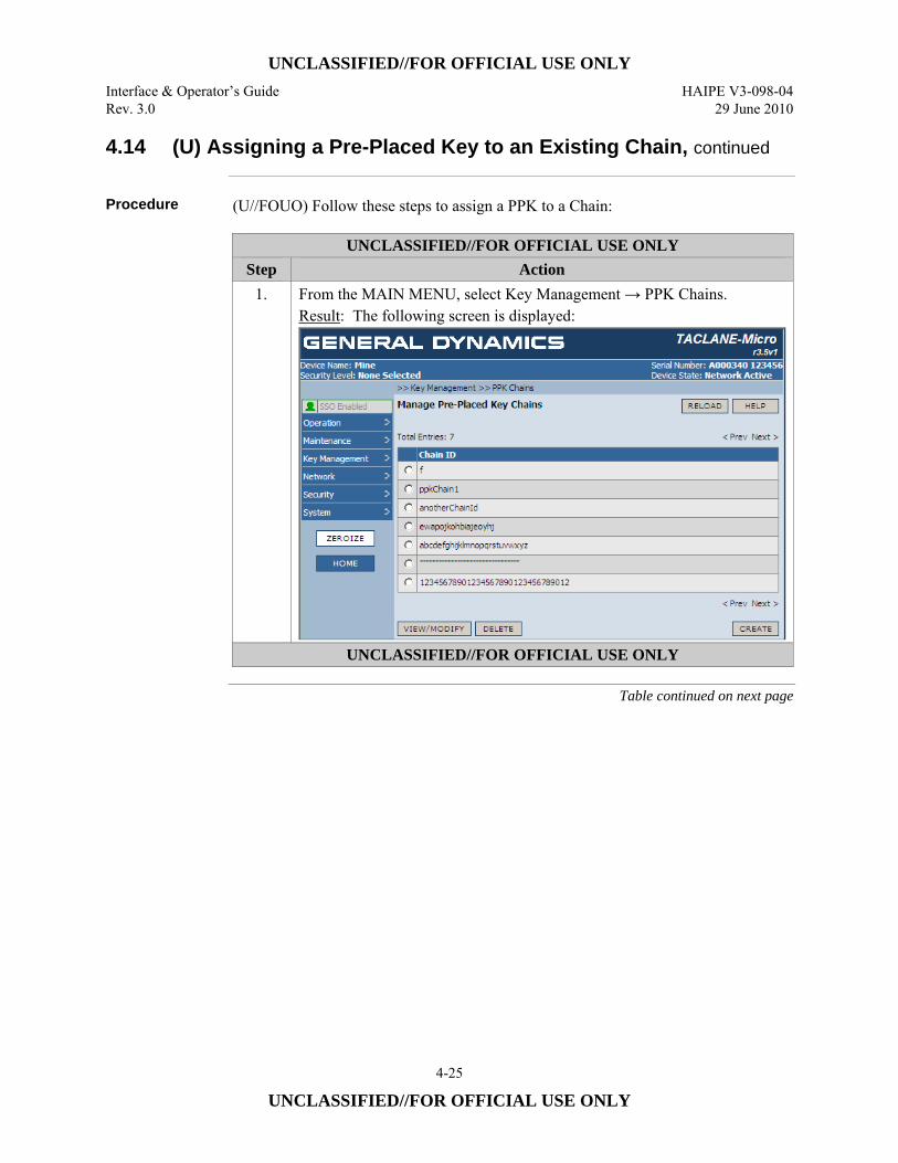
UNCLASSIFIED//FOR OFFICIAL USE ONLY Interface & Operator’s Guide HAIPE V3-098-04 Rev. 3.0 29 June 2010
4-25
UNCLASSIFIED//FOR OFFICIAL USE ONLY
4.14 (U) Assigning a Pre-Placed Key to an Existing Chain, continued
Procedure (U//FOUO) Follow these steps to assign a PPK to a Chain:
UNCLASSIFIED//FOR OFFICIAL USE ONLY Step Action
1. From the MAIN MENU, select Key Management → PPK Chains. Result: The following screen is displayed:
UNCLASSIFIED//FOR OFFICIAL USE ONLY
Table continued on next page
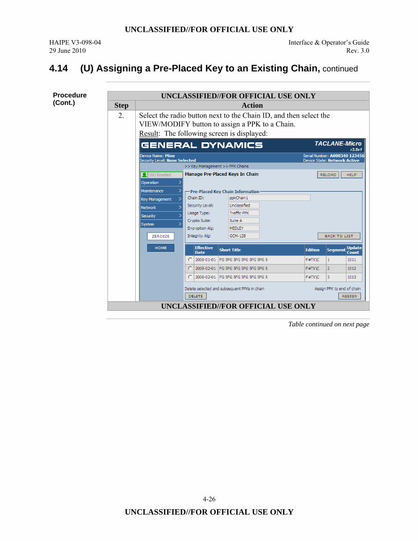
UNCLASSIFIED//FOR OFFICIAL USE ONLY HAIPE V3-098-04 Interface & Operator’s Guide 29 June 2010 Rev. 3.0
4-26
UNCLASSIFIED//FOR OFFICIAL USE ONLY
4.14 (U) Assigning a Pre-Placed Key to an Existing Chain, continued
Procedure (Cont.)
UNCLASSIFIED//FOR OFFICIAL USE ONLY Step Action
2. Select the radio button next to the Chain ID, and then select the VIEW/MODIFY button to assign a PPK to a Chain. Result: The following screen is displayed:
UNCLASSIFIED//FOR OFFICIAL USE ONLY
Table continued on next page
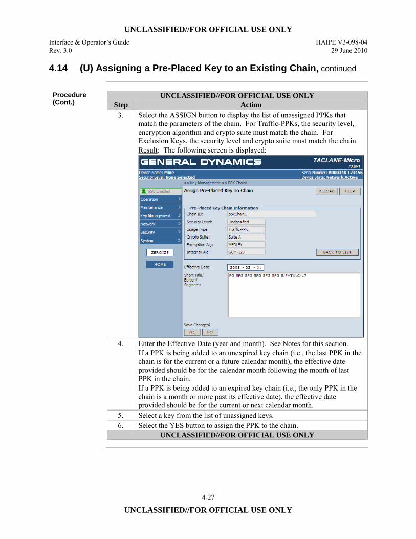
UNCLASSIFIED//FOR OFFICIAL USE ONLY Interface & Operator’s Guide HAIPE V3-098-04 Rev. 3.0 29 June 2010
4-27
UNCLASSIFIED//FOR OFFICIAL USE ONLY
4.14 (U) Assigning a Pre-Placed Key to an Existing Chain, continued
Procedure (Cont.)
UNCLASSIFIED//FOR OFFICIAL USE ONLY Step Action
3. Select the ASSIGN button to display the list of unassigned PPKs that match the parameters of the chain. For Traffic-PPKs, the security level, encryption algorithm and crypto suite must match the chain. For Exclusion Keys, the security level and crypto suite must match the chain. Result: The following screen is displayed:
4. Enter the Effective Date (year and month). See Notes for this section. If a PPK is being added to an unexpired key chain (i.e., the last PPK in the chain is for the current or a future calendar month), the effective date provided should be for the calendar month following the month of last PPK in the chain. If a PPK is being added to an expired key chain (i.e., the only PPK in the chain is a month or more past its effective date), the effective date provided should be for the current or next calendar month.
5. Select a key from the list of unassigned keys. 6. Select the YES button to assign the PPK to the chain.
UNCLASSIFIED//FOR OFFICIAL USE ONLY
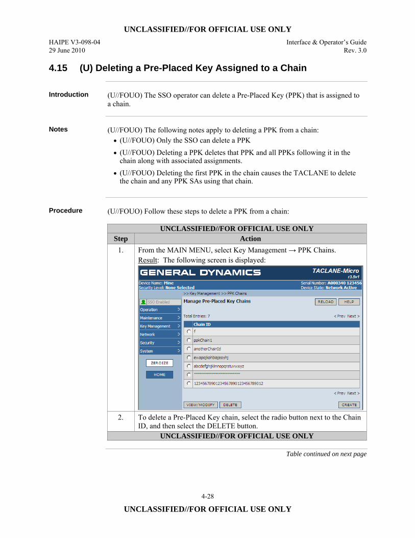
UNCLASSIFIED//FOR OFFICIAL USE ONLY HAIPE V3-098-04 Interface & Operator’s Guide 29 June 2010 Rev. 3.0
4-28
UNCLASSIFIED//FOR OFFICIAL USE ONLY
4.15 (U) Deleting a Pre-Placed Key Assigned to a Chain
Introduction (U//FOUO) The SSO operator can delete a Pre-Placed Key (PPK) that is assigned to
a chain.
Notes (U//FOUO) The following notes apply to deleting a PPK from a chain:
• (U//FOUO) Only the SSO can delete a PPK • (U//FOUO) Deleting a PPK deletes that PPK and all PPKs following it in the
chain along with associated assignments. • (U//FOUO) Deleting the first PPK in the chain causes the TACLANE to delete
the chain and any PPK SAs using that chain.
Procedure (U//FOUO) Follow these steps to delete a PPK from a chain:
UNCLASSIFIED//FOR OFFICIAL USE ONLY Step Action
1. From the MAIN MENU, select Key Management → PPK Chains. Result: The following screen is displayed:
2. To delete a Pre-Placed Key chain, select the radio button next to the Chain ID, and then select the DELETE button.
UNCLASSIFIED//FOR OFFICIAL USE ONLY
Table continued on next page
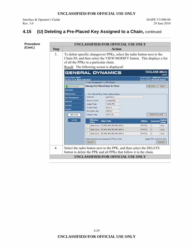
UNCLASSIFIED//FOR OFFICIAL USE ONLY Interface & Operator’s Guide HAIPE V3-098-04 Rev. 3.0 29 June 2010
4-29
UNCLASSIFIED//FOR OFFICIAL USE ONLY
4.15 (U) Deleting a Pre-Placed Key Assigned to a Chain, continued
Procedure (Cont.)
UNCLASSIFIED//FOR OFFICIAL USE ONLY Step Action
3. To delete specific changeover PPKs, select the radio button next to the Chain ID, and then select the VIEW/MODIFY button. This displays a list of all the PPKs in a particular chain. Result: The following screen is displayed:
4. Select the radio button next to the PPK, and then select the DELETE button to delete the PPK and all PPKs that follow it in the chain.
UNCLASSIFIED//FOR OFFICIAL USE ONLY
UNCLASSIFIED//FOR OFFICIAL USE ONLY HAIPE V3-098-04 Interface & Operator’s Guide 29 June 2010 Rev. 3.0
4-30
UNCLASSIFIED//FOR OFFICIAL USE ONLY
4.16 (U) Installing PAC
Introduction (U//FOUO) The TACLANE supports changing the Positive Access Control (PAC).
The base PAC and the alternate PACs can be updated. The base PAC is changed by a Change PAC Command (CPC). An alternate PAC is changed by a PACing Privilege Command (PPC). These commands are filled into the TACLANE from a DTD (or equivalent). The PAC is considered available for install at that point. Only one PAC available for install can exist in the TACLANE. In order to fill another CPC or PPC, the PAC available for install must be installed or discarded (see next section).
Notes (U//FOUO) The following notes apply to installing PAC:
• Only the SSO can Install PAC • One base PAC and 6 alternate PACs are supported
Continued on next page
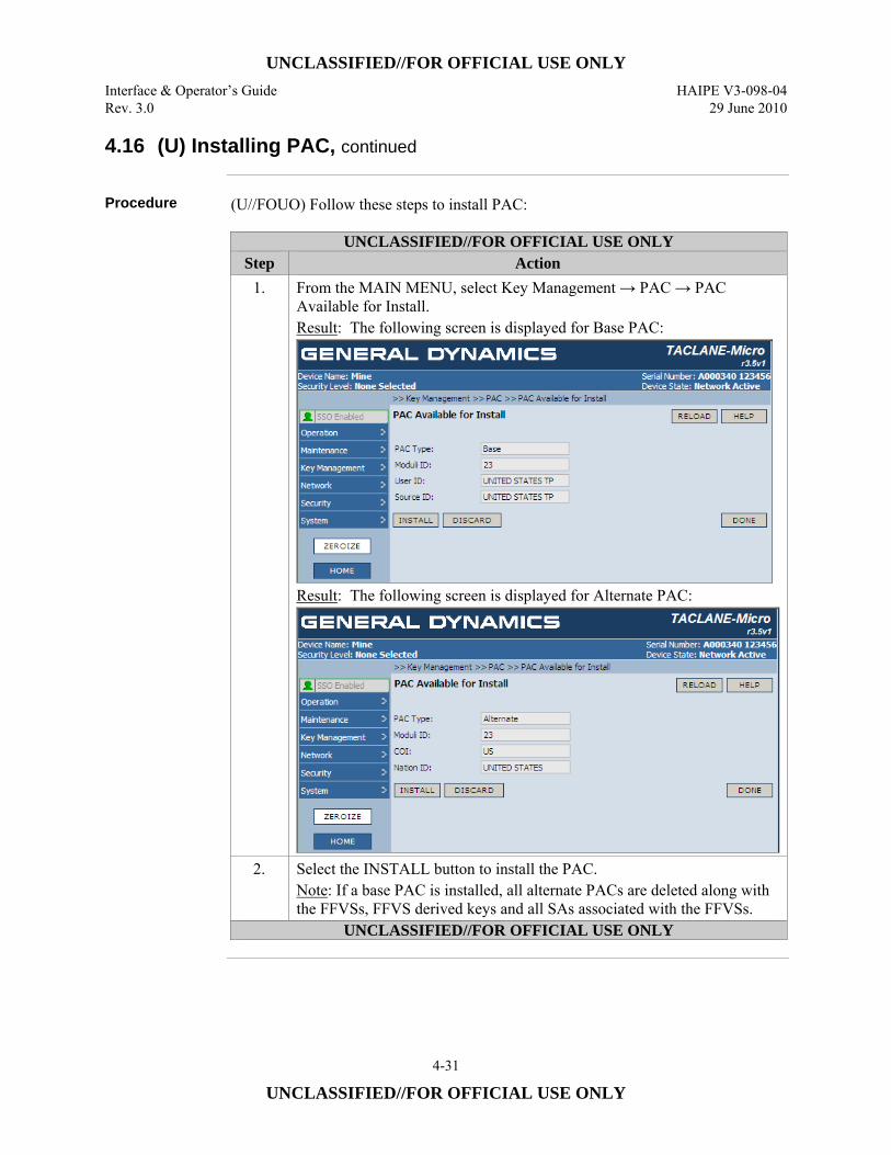
UNCLASSIFIED//FOR OFFICIAL USE ONLY Interface & Operator’s Guide HAIPE V3-098-04 Rev. 3.0 29 June 2010
4-31
UNCLASSIFIED//FOR OFFICIAL USE ONLY
4.16 (U) Installing PAC, continued
Procedure (U//FOUO) Follow these steps to install PAC:
UNCLASSIFIED//FOR OFFICIAL USE ONLY Step Action
1. From the MAIN MENU, select Key Management → PAC → PAC Available for Install. Result: The following screen is displayed for Base PAC:
Result: The following screen is displayed for Alternate PAC:
2. Select the INSTALL button to install the PAC. Note: If a base PAC is installed, all alternate PACs are deleted along with the FFVSs, FFVS derived keys and all SAs associated with the FFVSs.
UNCLASSIFIED//FOR OFFICIAL USE ONLY
UNCLASSIFIED//FOR OFFICIAL USE ONLY HAIPE V3-098-04 Interface & Operator’s Guide 29 June 2010 Rev. 3.0
4-32
UNCLASSIFIED//FOR OFFICIAL USE ONLY
4.17 (U) Discarding PAC Available for Install
Introduction (U//FOUO) The TACLANE supports discarding the PAC available for install. Only
one PAC available for install can exist in the TACLANE. In order to fill another CPC or PPC, the PAC available for install must be installed (see previous section) or discarded.
Notes (U//FOUO) The following notes apply to discarding PAC available for install:
• Only the SSO can discard PAC available for install.
Continued on next page
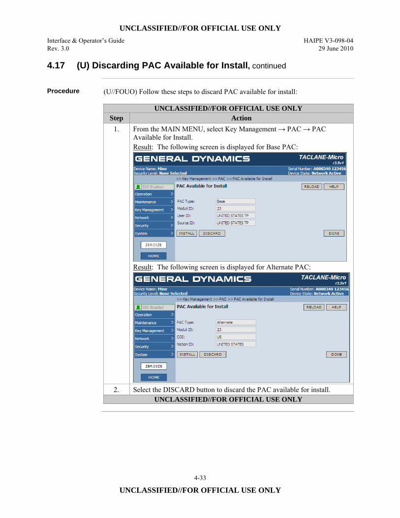
UNCLASSIFIED//FOR OFFICIAL USE ONLY Interface & Operator’s Guide HAIPE V3-098-04 Rev. 3.0 29 June 2010
4-33
UNCLASSIFIED//FOR OFFICIAL USE ONLY
4.17 (U) Discarding PAC Available for Install, continued
Procedure (U//FOUO) Follow these steps to discard PAC available for install:
UNCLASSIFIED//FOR OFFICIAL USE ONLY Step Action
1. From the MAIN MENU, select Key Management → PAC → PAC Available for Install. Result: The following screen is displayed for Base PAC:
Result: The following screen is displayed for Alternate PAC:
2. Select the DISCARD button to discard the PAC available for install. UNCLASSIFIED//FOR OFFICIAL USE ONLY
UNCLASSIFIED//FOR OFFICIAL USE ONLY HAIPE V3-098-04 Interface & Operator’s Guide 29 June 2010 Rev. 3.0
4-34
UNCLASSIFIED//FOR OFFICIAL USE ONLY
4.18 (U) Deleting Installed PAC
Introduction (U//FOUO) The TACLANE supports deleting installed alternate PACs.
Notes (U//FOUO) The following notes apply to deleting installed PAC:
• Only the SSO can discard installed alternate PACs. • The base PAC cannot be deleted.
Continued on next page
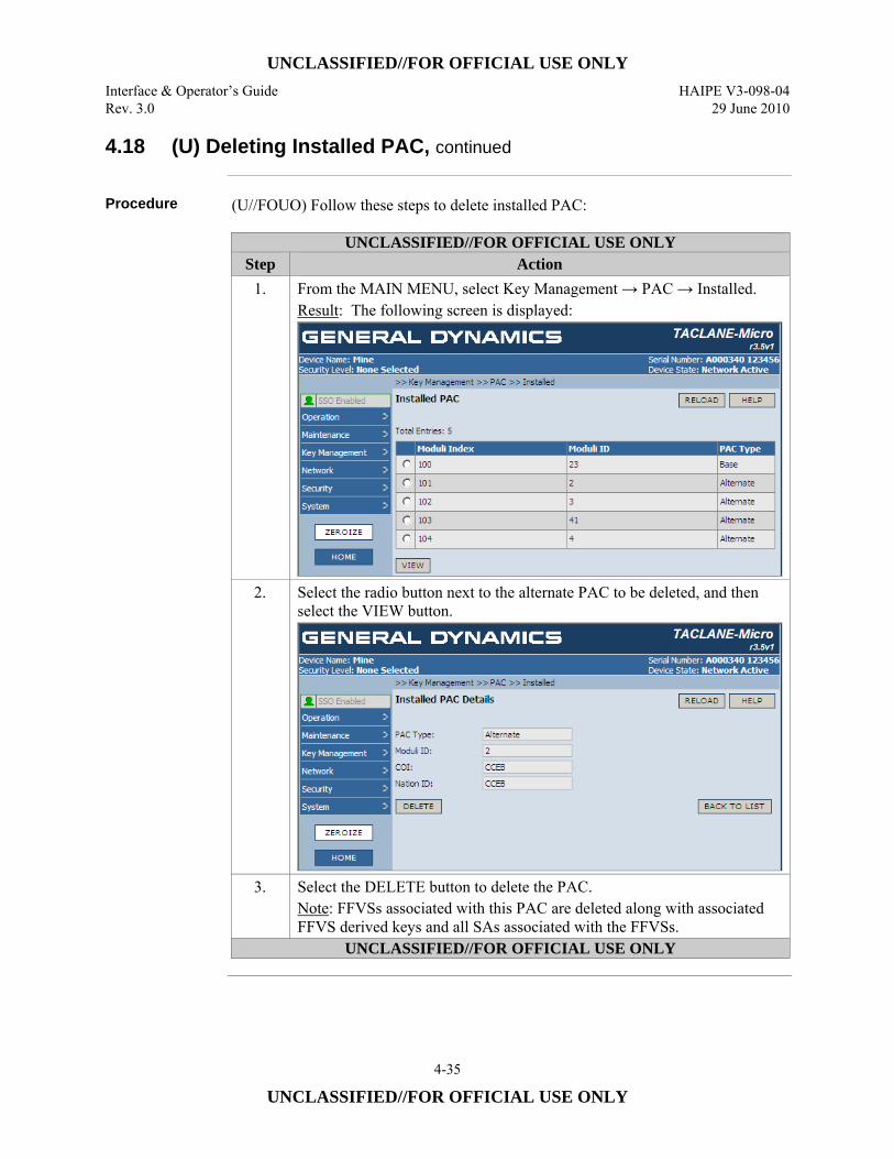
UNCLASSIFIED//FOR OFFICIAL USE ONLY Interface & Operator’s Guide HAIPE V3-098-04 Rev. 3.0 29 June 2010
4-35
UNCLASSIFIED//FOR OFFICIAL USE ONLY
4.18 (U) Deleting Installed PAC, continued
Procedure (U//FOUO) Follow these steps to delete installed PAC:
UNCLASSIFIED//FOR OFFICIAL USE ONLY Step Action
1. From the MAIN MENU, select Key Management → PAC → Installed. Result: The following screen is displayed:
2. Select the radio button next to the alternate PAC to be deleted, and then select the VIEW button.
3. Select the DELETE button to delete the PAC. Note: FFVSs associated with this PAC are deleted along with associated FFVS derived keys and all SAs associated with the FFVSs.
UNCLASSIFIED//FOR OFFICIAL USE ONLY
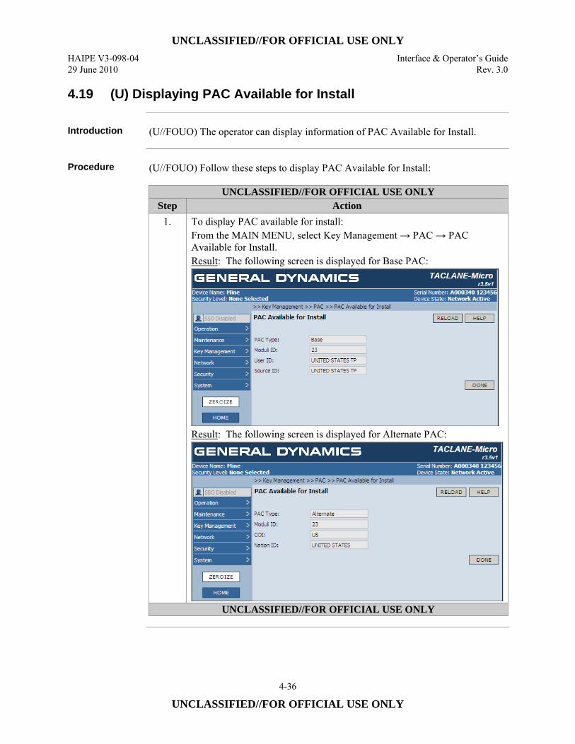
UNCLASSIFIED//FOR OFFICIAL USE ONLY HAIPE V3-098-04 Interface & Operator’s Guide 29 June 2010 Rev. 3.0
4-36
UNCLASSIFIED//FOR OFFICIAL USE ONLY
4.19 (U) Displaying PAC Available for Install
Introduction (U//FOUO) The operator can display information of PAC Available for Install.
Procedure (U//FOUO) Follow these steps to display PAC Available for Install:
UNCLASSIFIED//FOR OFFICIAL USE ONLY Step Action
1. To display PAC available for install: From the MAIN MENU, select Key Management → PAC → PAC Available for Install. Result: The following screen is displayed for Base PAC:
Result: The following screen is displayed for Alternate PAC:
UNCLASSIFIED//FOR OFFICIAL USE ONLY
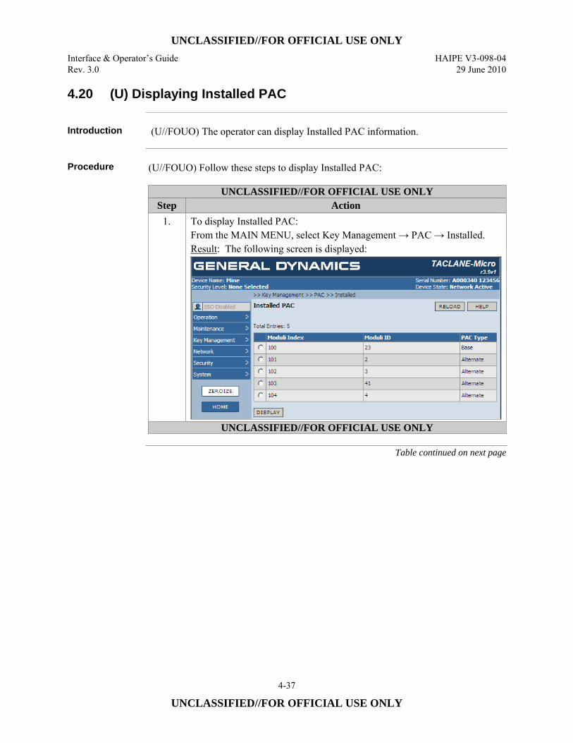
UNCLASSIFIED//FOR OFFICIAL USE ONLY Interface & Operator’s Guide HAIPE V3-098-04 Rev. 3.0 29 June 2010
4-37
UNCLASSIFIED//FOR OFFICIAL USE ONLY
4.20 (U) Displaying Installed PAC
Introduction (U//FOUO) The operator can display Installed PAC information.
Procedure (U//FOUO) Follow these steps to display Installed PAC:
UNCLASSIFIED//FOR OFFICIAL USE ONLY Step Action
1. To display Installed PAC: From the MAIN MENU, select Key Management → PAC → Installed. Result: The following screen is displayed:
UNCLASSIFIED//FOR OFFICIAL USE ONLY
Table continued on next page
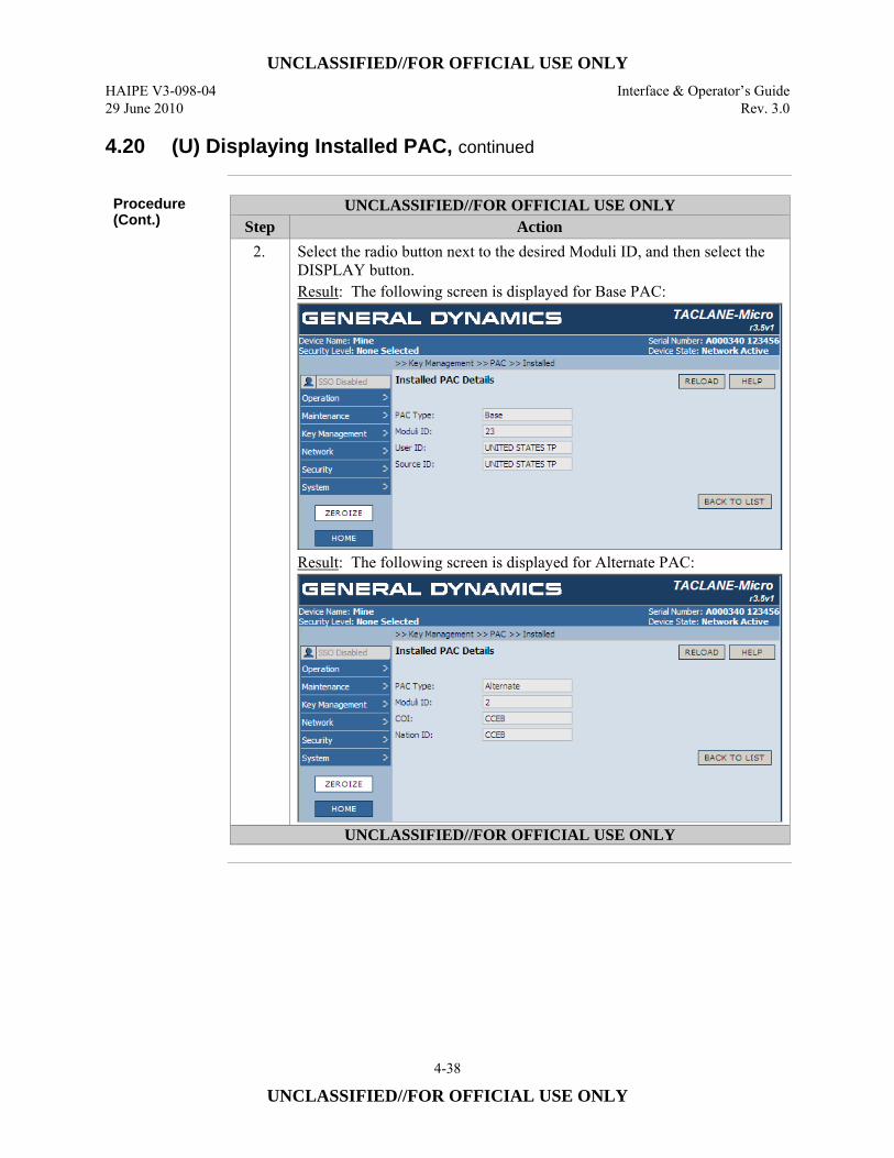
UNCLASSIFIED//FOR OFFICIAL USE ONLY HAIPE V3-098-04 Interface & Operator’s Guide 29 June 2010 Rev. 3.0
4-38
UNCLASSIFIED//FOR OFFICIAL USE ONLY
4.20 (U) Displaying Installed PAC, continued
Procedure (Cont.)
UNCLASSIFIED//FOR OFFICIAL USE ONLY Step Action
2. Select the radio button next to the desired Moduli ID, and then select the DISPLAY button. Result: The following screen is displayed for Base PAC:
Result: The following screen is displayed for Alternate PAC:
UNCLASSIFIED//FOR OFFICIAL USE ONLY
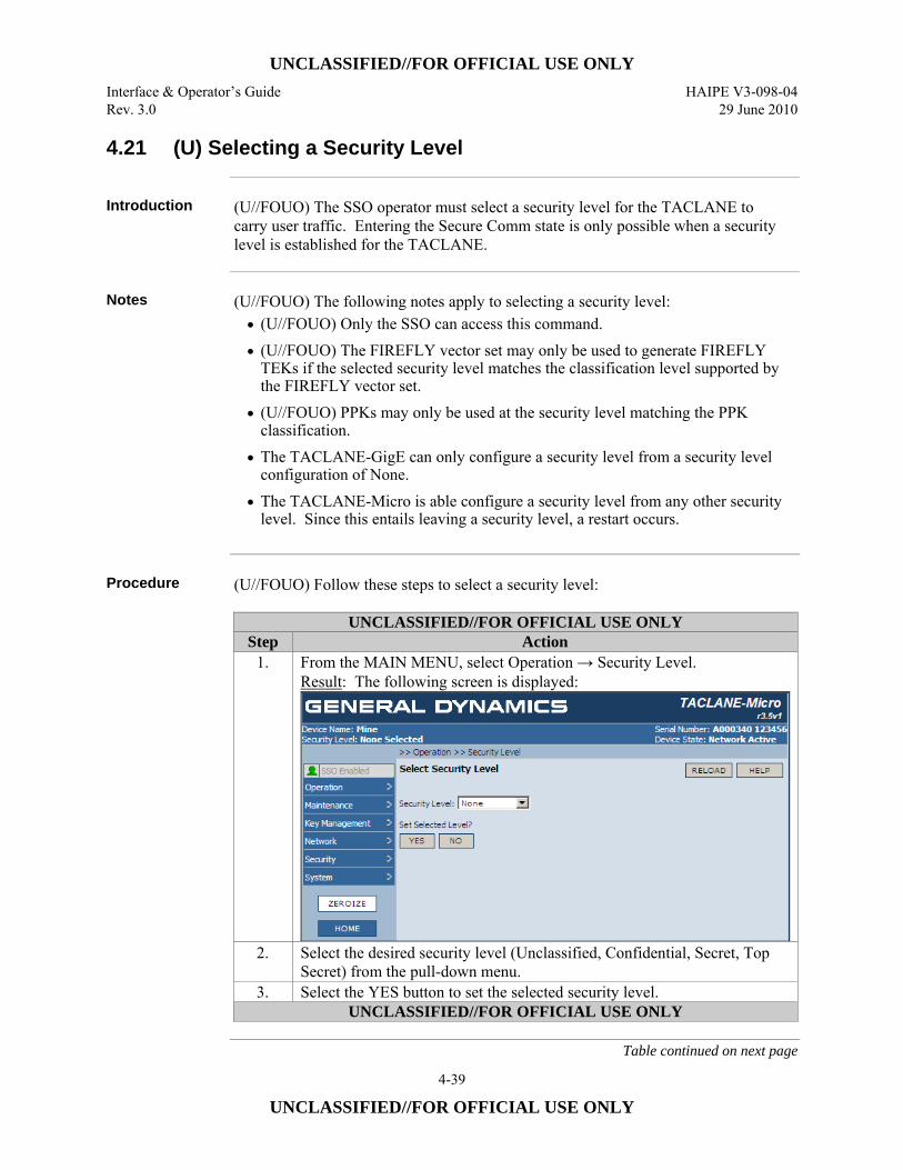
UNCLASSIFIED//FOR OFFICIAL USE ONLY Interface & Operator’s Guide HAIPE V3-098-04 Rev. 3.0 29 June 2010
4-39
UNCLASSIFIED//FOR OFFICIAL USE ONLY
4.21 (U) Selecting a Security Level
Introduction (U//FOUO) The SSO operator must select a security level for the TACLANE to
carry user traffic. Entering the Secure Comm state is only possible when a security level is established for the TACLANE.
Notes (U//FOUO) The following notes apply to selecting a security level:
• (U//FOUO) Only the SSO can access this command. • (U//FOUO) The FIREFLY vector set may only be used to generate FIREFLY
TEKs if the selected security level matches the classification level supported by the FIREFLY vector set.
• (U//FOUO) PPKs may only be used at the security level matching the PPK classification.
• The TACLANE-GigE can only configure a security level from a security level configuration of None.
• The TACLANE-Micro is able configure a security level from any other security level. Since this entails leaving a security level, a restart occurs.
Procedure (U//FOUO) Follow these steps to select a security level:
UNCLASSIFIED//FOR OFFICIAL USE ONLY Step Action
1. From the MAIN MENU, select Operation → Security Level. Result: The following screen is displayed:
2. Select the desired security level (Unclassified, Confidential, Secret, Top Secret) from the pull-down menu.
3. Select the YES button to set the selected security level. UNCLASSIFIED//FOR OFFICIAL USE ONLY
Table continued on next page
UNCLASSIFIED//FOR OFFICIAL USE ONLY HAIPE V3-098-04 Interface & Operator’s Guide 29 June 2010 Rev. 3.0
4-40
UNCLASSIFIED//FOR OFFICIAL USE ONLY
4.21 (U) Selecting a Security Level, continued
Procedure (Cont.)
UNCLASSIFIED//FOR OFFICIAL USE ONLY Step Action
4. Select the OK button in the dialog box to confirm the action and restart the TACLANE (if currently in a security level). Note: This confirmation is displayed to alert the operator that existing communications, including communications with a Network Manager, will be lost if this change is made.
UNCLASSIFIED//FOR OFFICIAL USE ONLY
4.22 (U) Exiting a Security Level
Introduction (U//FOUO) The SSO operator can exit the current security level, returning to
“none”.
Notes (U//FOUO) The following notes apply to exiting a security level:
• Only the SSO can access this command. • The TACLANE will restart upon execution of this command. • The TACLANE-GigE, will zeroize when exiting a security level, deleting all key
material within the device.
Continued on next page
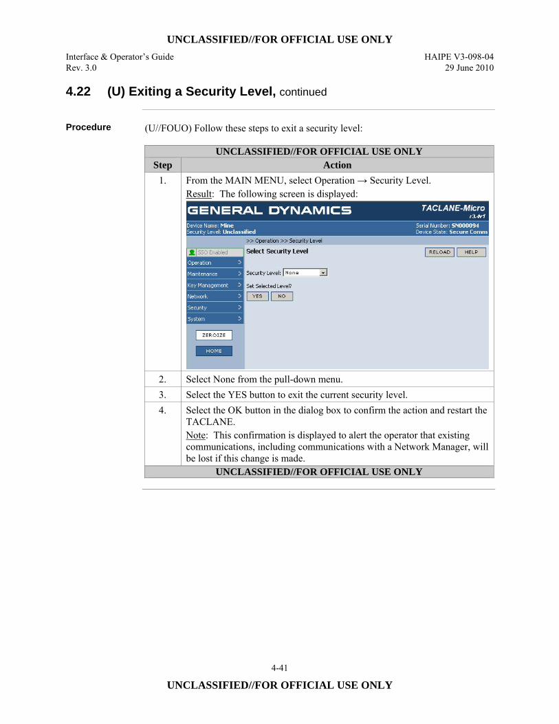
UNCLASSIFIED//FOR OFFICIAL USE ONLY Interface & Operator’s Guide HAIPE V3-098-04 Rev. 3.0 29 June 2010
4-41
UNCLASSIFIED//FOR OFFICIAL USE ONLY
4.22 (U) Exiting a Security Level, continued
Procedure (U//FOUO) Follow these steps to exit a security level:
UNCLASSIFIED//FOR OFFICIAL USE ONLY Step Action
1. From the MAIN MENU, select Operation → Security Level. Result: The following screen is displayed:
2. Select None from the pull-down menu. 3. Select the YES button to exit the current security level. 4. Select the OK button in the dialog box to confirm the action and restart the
TACLANE. Note: This confirmation is displayed to alert the operator that existing communications, including communications with a Network Manager, will be lost if this change is made.
UNCLASSIFIED//FOR OFFICIAL USE ONLY
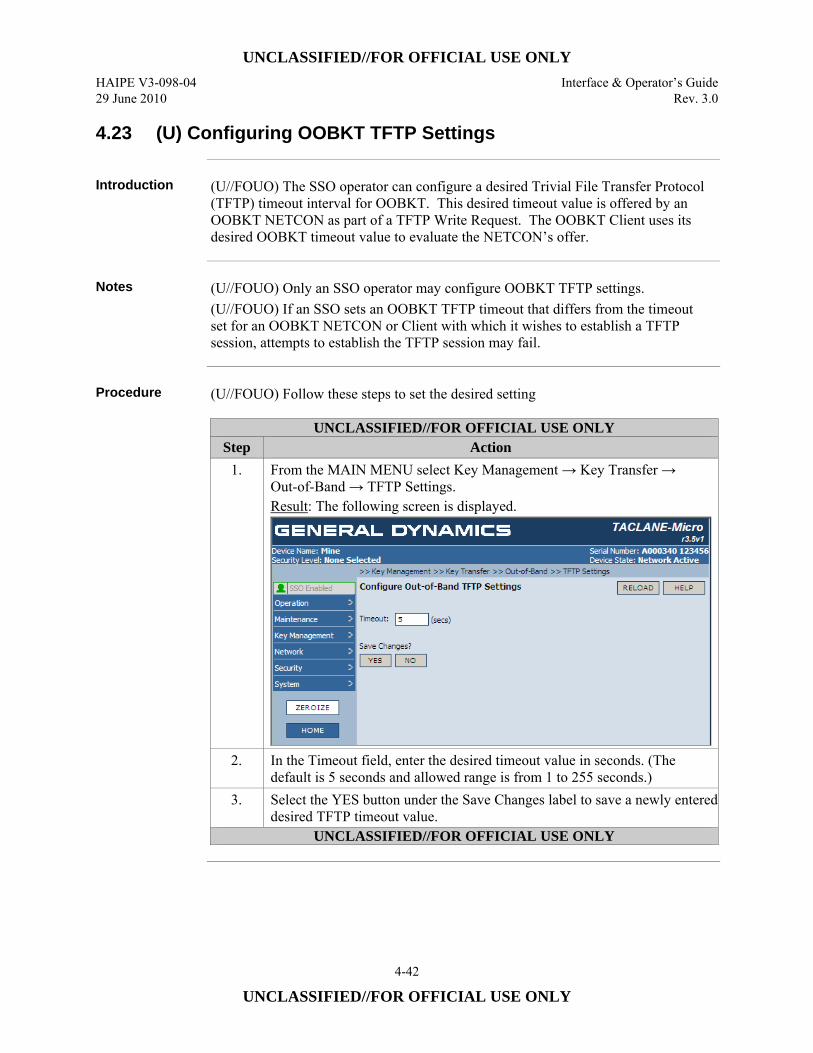
UNCLASSIFIED//FOR OFFICIAL USE ONLY HAIPE V3-098-04 Interface & Operator’s Guide 29 June 2010 Rev. 3.0
4-42
UNCLASSIFIED//FOR OFFICIAL USE ONLY
4.23 (U) Configuring OOBKT TFTP Settings
Introduction (U//FOUO) The SSO operator can configure a desired Trivial File Transfer Protocol
(TFTP) timeout interval for OOBKT. This desired timeout value is offered by an OOBKT NETCON as part of a TFTP Write Request. The OOBKT Client uses its desired OOBKT timeout value to evaluate the NETCON’s offer.
Notes (U//FOUO) Only an SSO operator may configure OOBKT TFTP settings.
(U//FOUO) If an SSO sets an OOBKT TFTP timeout that differs from the timeout set for an OOBKT NETCON or Client with which it wishes to establish a TFTP session, attempts to establish the TFTP session may fail.
Procedure (U//FOUO) Follow these steps to set the desired setting
UNCLASSIFIED//FOR OFFICIAL USE ONLY Step Action
1. From the MAIN MENU select Key Management → Key Transfer → Out-of-Band → TFTP Settings. Result: The following screen is displayed.
2. In the Timeout field, enter the desired timeout value in seconds. (The default is 5 seconds and allowed range is from 1 to 255 seconds.)
3. Select the YES button under the Save Changes label to save a newly entered desired TFTP timeout value.
UNCLASSIFIED//FOR OFFICIAL USE ONLY
UNCLASSIFIED//FOR OFFICIAL USE ONLY Interface & Operator’s Guide HAIPE V3-098-04 Rev. 3.0 29 June 2010
4-43
UNCLASSIFIED//FOR OFFICIAL USE ONLY
4.24 (U) Displaying OOBKT NETCON Key Files
Introduction (U//FOUO) An operator may view key files that are candidates for transfer to
OOBKT Clients and inspect the keys associated with individual key files.
Notes (U//FOUO) A key file may identify a single enhanced FFVS as denoted by a Key
Use of EFF or it may identify from one to a maximum of twelve PPKs as denoted by a Key Use of PPK/APPK. The TACLANE does not support the definition of empty key files. (U//FOUO) The Security Level of the key file indicates the security classification level associated with the key or keys defined in the file. All keys in a given key file must be at the same security classification level. A single PPK/APPK key file may identify keys used for different cryptographic suites (i.e., Suite A and/or AES EFF). (U//FOUO) The TACLANE supports the definition of up to 96 key file name-key pairs (i.e., the total number of keys identified in all the defined files must be 96 or less). (U//FOUO) The keys identified in a key file are issue-formatted keys stored in the TACLANE. If an operator deletes a key identified in the OOBKT key file table from the TACLANE issued key storage, the key file name-key pairs associated with the deleted key are automatically removed. If the deleted key is the only entry in a key file, the named key file is removed. If the deleted key is identified in a key file with other keys, only the deleted key is removed as an entry in the key file.
Procedure (U//FOUO) Follow these steps to view an OOBKT Key File:
Continued on next page
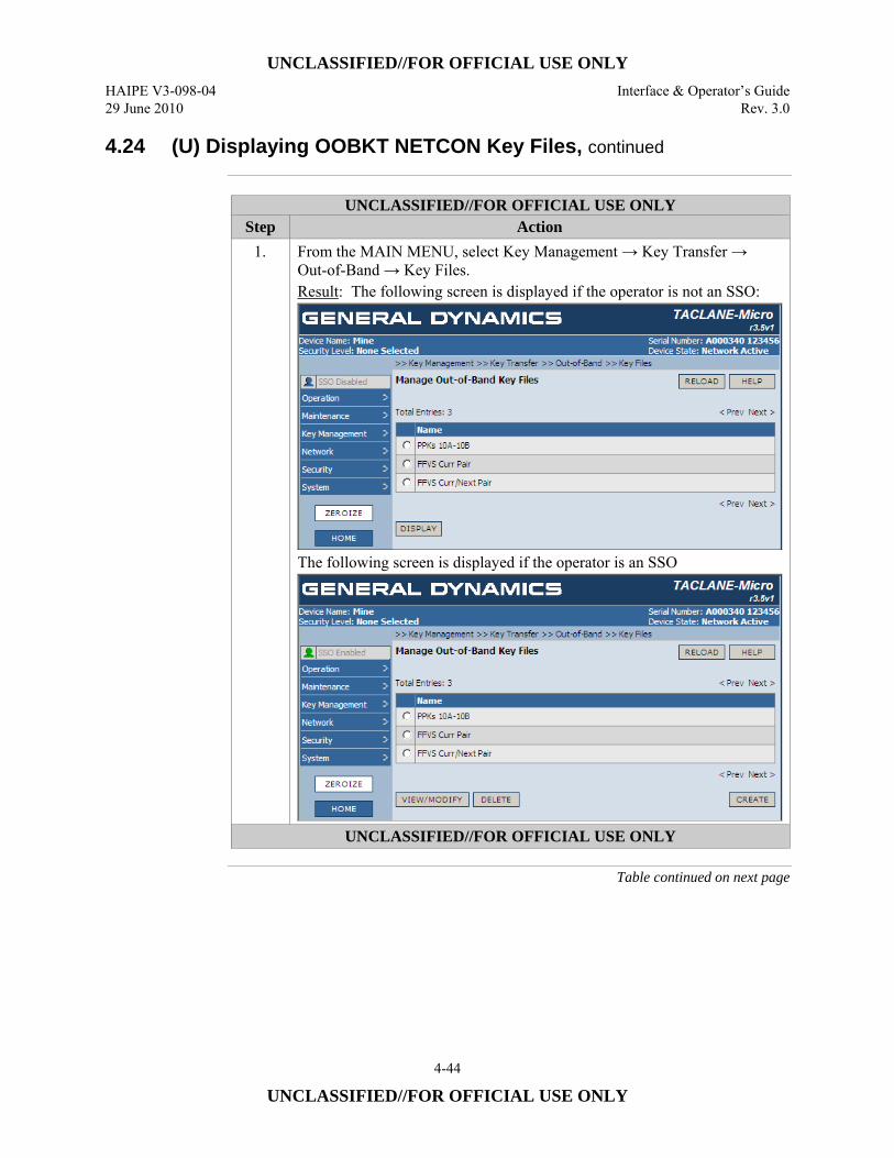
UNCLASSIFIED//FOR OFFICIAL USE ONLY HAIPE V3-098-04 Interface & Operator’s Guide 29 June 2010 Rev. 3.0
4-44
UNCLASSIFIED//FOR OFFICIAL USE ONLY
4.24 (U) Displaying OOBKT NETCON Key Files, continued
UNCLASSIFIED//FOR OFFICIAL USE ONLY
Step Action 1. From the MAIN MENU, select Key Management → Key Transfer →
Out-of-Band → Key Files. Result: The following screen is displayed if the operator is not an SSO:
The following screen is displayed if the operator is an SSO
UNCLASSIFIED//FOR OFFICIAL USE ONLY
Table continued on next page
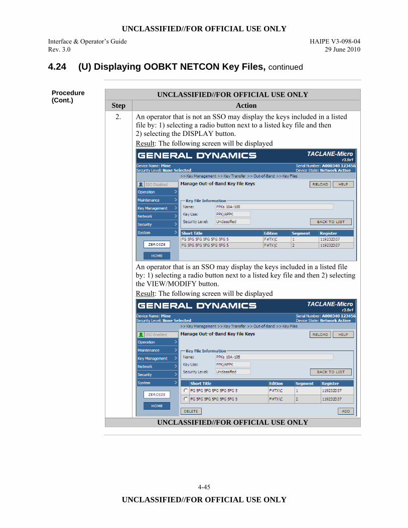
UNCLASSIFIED//FOR OFFICIAL USE ONLY Interface & Operator’s Guide HAIPE V3-098-04 Rev. 3.0 29 June 2010
4-45
UNCLASSIFIED//FOR OFFICIAL USE ONLY
4.24 (U) Displaying OOBKT NETCON Key Files, continued
Procedure (Cont.)
UNCLASSIFIED//FOR OFFICIAL USE ONLY Step Action
2. An operator that is not an SSO may display the keys included in a listed file by: 1) selecting a radio button next to a listed key file and then 2) selecting the DISPLAY button. Result: The following screen will be displayed
An operator that is an SSO may display the keys included in a listed file by: 1) selecting a radio button next to a listed key file and then 2) selecting the VIEW/MODIFY button. Result: The following screen will be displayed
UNCLASSIFIED//FOR OFFICIAL USE ONLY
UNCLASSIFIED//FOR OFFICIAL USE ONLY HAIPE V3-098-04 Interface & Operator’s Guide 29 June 2010 Rev. 3.0
4-46
UNCLASSIFIED//FOR OFFICIAL USE ONLY
4.25 (U) Creating an OOBKT NETCON Key File
Introduction (U//FOUO) An SSO operator may define a new key file as a candidate for transfer to
one or more OOBKT Clients.
Notes (U//FOUO) Only an SSO operator may create an OOBKT NETCON Key File.
(U//FOUO) When an SSO operator creates a key file, it must have a key file name that is unique within the TACLANE and contain one key. (U//FOUO) The key file name, key use, and classification defined for a key file cannot be modified once the key file definition is saved. If any of these parameters need to be changed, the key file will need to be deleted and then recreated with the new attributes. (U//FOUO) A key file may identify a single enhanced FFVS or up to 12 PPKs stored in issue-format in the TACLANE. When a file identifies multiple PPKs, the PPKs must have the same security classification level. A PPK/APPK key file may identify keys with different cryptographic suites (i.e., Suite A PPKs and AES EFF APPKs can be identified in the same file). (U//FOUO) The classification of the Transfer SA used to send a key file must equal or exceed the key file classification level. (U//FOUO) The TACLANE supports up to 96 key file name-key pairs (i.e., the total number of keys identified in all the defined files must be 96 or less).
Procedure (U//FOUO) Follow these steps to define a new OOBKT Key File:
Continued on next page
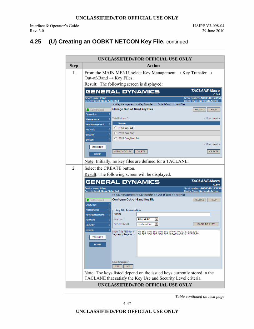
UNCLASSIFIED//FOR OFFICIAL USE ONLY Interface & Operator’s Guide HAIPE V3-098-04 Rev. 3.0 29 June 2010
4-47
UNCLASSIFIED//FOR OFFICIAL USE ONLY
4.25 (U) Creating an OOBKT NETCON Key File, continued
UNCLASSIFIED//FOR OFFICIAL USE ONLY
Step Action 1. From the MAIN MENU, select Key Management → Key Transfer →
Out-of-Band → Key Files. Result: The following screen is displayed:
Note: Initially, no key files are defined for a TACLANE.
2. Select the CREATE button. Result: The following screen will be displayed.
Note: The keys listed depend on the issued keys currently stored in the TACLANE that satisfy the Key Use and Security Level criteria.
UNCLASSIFIED//FOR OFFICIAL USE ONLY
Table continued on next page
UNCLASSIFIED//FOR OFFICIAL USE ONLY HAIPE V3-098-04 Interface & Operator’s Guide 29 June 2010 Rev. 3.0
4-48
UNCLASSIFIED//FOR OFFICIAL USE ONLY
4.25 (U) Creating an OOBKT NETCON Key File, continued
Procedure (Cont.)
UNCLASSIFIED//FOR OFFICIAL USE ONLY Step Action
3. Enter a name for the key file (consisting of between 1 and 32 characters) in the Name field. Note: The name entered must not duplicate a key file name currently defined in the TACLANE. Once the name is defined and saved, the operator will not be able to change the name except by deleting the key file and starting over.
4. Select the kind of key the file will identify (i.e., either traditional PPK/APPK or an enhanced FIREFLY (EFF)) in the Key Use pull down menu. Note: Once the key file use is selected and saved, the operator will not be able to change the use except by deleting the key file and starting over.
5. Select the security level the file will support from the Security Level pull down menu. Note: A key file can only be transferred when the classification of the Transfer SA to the remote Client equals or exceeds this security level. As in the case of the key file name and use, this key file attribute cannot be modified once selected and saved except by deleting and redefining the key file.
6. Select the first key to be identified in the key file from the filtered set of keys listed by Short Title, Edition, Segment, and Register. Only issued keys stored in the TACLANE meeting the identified Key Use and Security Level criteria are shown.
7. Select the YES button under the Save Changes label to save the key file definition
UNCLASSIFIED//FOR OFFICIAL USE ONLY
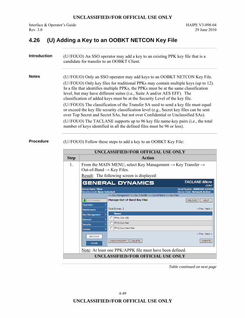
UNCLASSIFIED//FOR OFFICIAL USE ONLY Interface & Operator’s Guide HAIPE V3-098-04 Rev. 3.0 29 June 2010
4-49
UNCLASSIFIED//FOR OFFICIAL USE ONLY
4.26 (U) Adding a Key to an OOBKT NETCON Key File
Introduction (U//FOUO) An SSO operator may add a key to an existing PPK key file that is a
candidate for transfer to an OOBKT Client.
Notes (U//FOUO) Only an SSO operator may add keys to an OOBKT NETCON Key File.
(U//FOUO) Only key files for traditional PPKs may contain multiple keys (up to 12). In a file that identifies multiple PPKs, the PPKs must be at the same classification level, but may have different suites (i.e., Suite A and/or AES EFF). The classification of added keys must be at the Security Level of the key file. (U//FOUO) The classification of the Transfer SA used to send a key file must equal or exceed the key file security classification level (e.g., Secret key files can be sent over Top Secret and Secret SAs, but not over Confidential or Unclassified SAs). (U//FOUO) The TACLANE supports up to 96 key file name-key pairs (i.e., the total number of keys identified in all the defined files must be 96 or less).
Procedure (U//FOUO) Follow these steps to add a key to an OOBKT Key File:
UNCLASSIFIED//FOR OFFICIAL USE ONLY Step Action
1. From the MAIN MENU, select Key Management → Key Transfer → Out-of-Band → Key Files. Result: The following screen is displayed:
Note: At least one PPK/APPK file must have been defined.
UNCLASSIFIED//FOR OFFICIAL USE ONLY
Table continued on next page
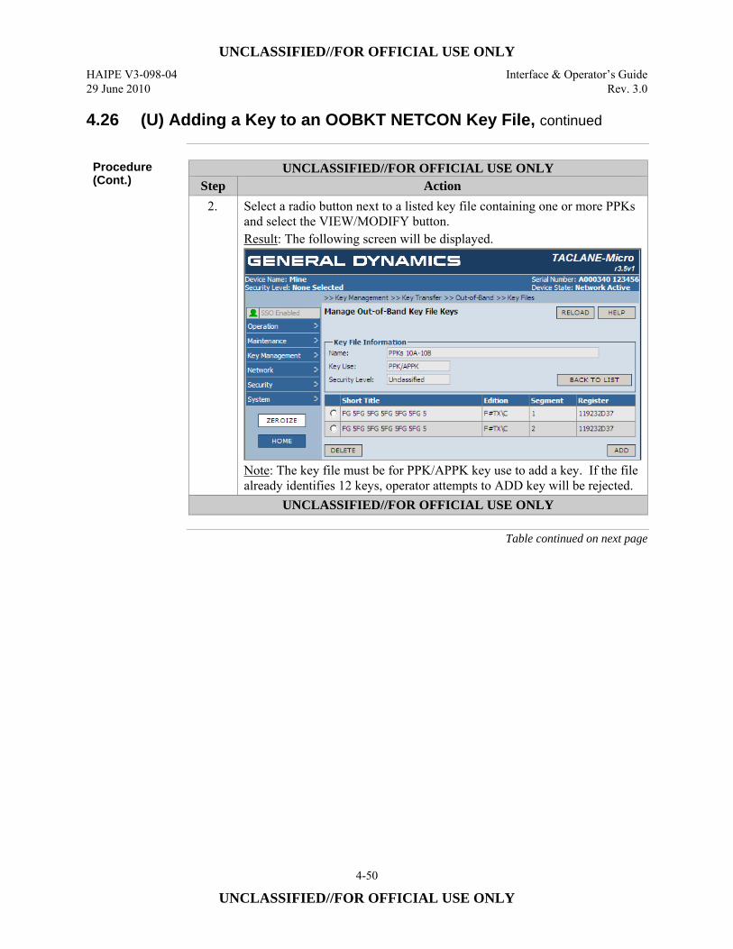
UNCLASSIFIED//FOR OFFICIAL USE ONLY HAIPE V3-098-04 Interface & Operator’s Guide 29 June 2010 Rev. 3.0
4-50
UNCLASSIFIED//FOR OFFICIAL USE ONLY
4.26 (U) Adding a Key to an OOBKT NETCON Key File, continued
Procedure (Cont.)
UNCLASSIFIED//FOR OFFICIAL USE ONLY Step Action
2. Select a radio button next to a listed key file containing one or more PPKs and select the VIEW/MODIFY button. Result: The following screen will be displayed.
Note: The key file must be for PPK/APPK key use to add a key. If the file already identifies 12 keys, operator attempts to ADD key will be rejected.
UNCLASSIFIED//FOR OFFICIAL USE ONLY
Table continued on next page
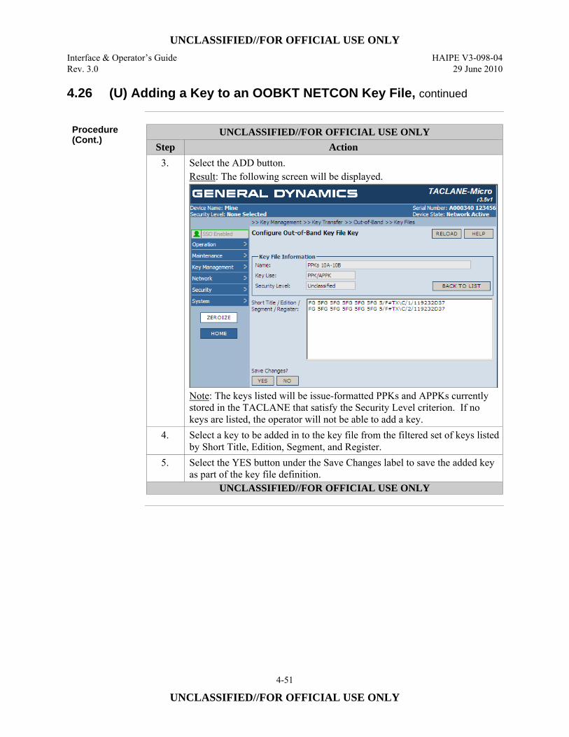
UNCLASSIFIED//FOR OFFICIAL USE ONLY Interface & Operator’s Guide HAIPE V3-098-04 Rev. 3.0 29 June 2010
4-51
UNCLASSIFIED//FOR OFFICIAL USE ONLY
4.26 (U) Adding a Key to an OOBKT NETCON Key File, continued
Procedure (Cont.)
UNCLASSIFIED//FOR OFFICIAL USE ONLY Step Action
3. Select the ADD button. Result: The following screen will be displayed.
Note: The keys listed will be issue-formatted PPKs and APPKs currently stored in the TACLANE that satisfy the Security Level criterion. If no keys are listed, the operator will not be able to add a key.
4. Select a key to be added in to the key file from the filtered set of keys listed by Short Title, Edition, Segment, and Register.
5. Select the YES button under the Save Changes label to save the added key as part of the key file definition.
UNCLASSIFIED//FOR OFFICIAL USE ONLY
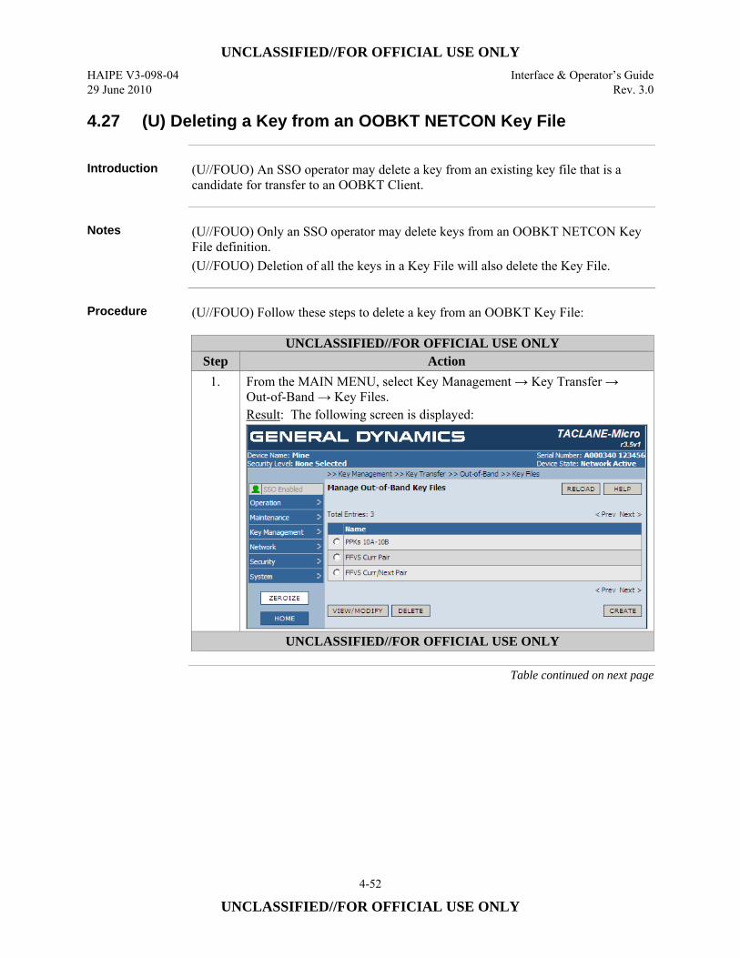
UNCLASSIFIED//FOR OFFICIAL USE ONLY HAIPE V3-098-04 Interface & Operator’s Guide 29 June 2010 Rev. 3.0
4-52
UNCLASSIFIED//FOR OFFICIAL USE ONLY
4.27 (U) Deleting a Key from an OOBKT NETCON Key File
Introduction (U//FOUO) An SSO operator may delete a key from an existing key file that is a
candidate for transfer to an OOBKT Client.
Notes (U//FOUO) Only an SSO operator may delete keys from an OOBKT NETCON Key
File definition. (U//FOUO) Deletion of all the keys in a Key File will also delete the Key File.
Procedure (U//FOUO) Follow these steps to delete a key from an OOBKT Key File:
UNCLASSIFIED//FOR OFFICIAL USE ONLY Step Action
1. From the MAIN MENU, select Key Management → Key Transfer → Out-of-Band → Key Files. Result: The following screen is displayed:
UNCLASSIFIED//FOR OFFICIAL USE ONLY
Table continued on next page
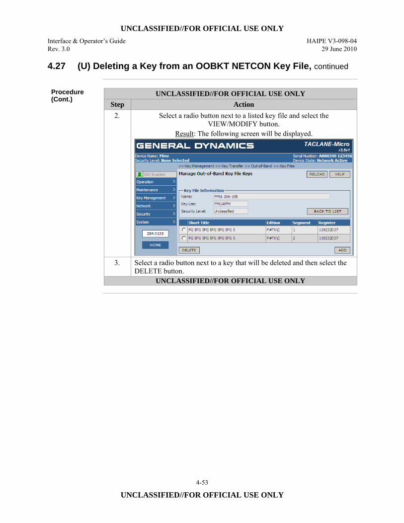
UNCLASSIFIED//FOR OFFICIAL USE ONLY Interface & Operator’s Guide HAIPE V3-098-04 Rev. 3.0 29 June 2010
4-53
UNCLASSIFIED//FOR OFFICIAL USE ONLY
4.27 (U) Deleting a Key from an OOBKT NETCON Key File, continued
Procedure (Cont.)
UNCLASSIFIED//FOR OFFICIAL USE ONLY Step Action
2. Select a radio button next to a listed key file and select the VIEW/MODIFY button.
Result: The following screen will be displayed.
3. Select a radio button next to a key that will be deleted and then select the DELETE button.
UNCLASSIFIED//FOR OFFICIAL USE ONLY
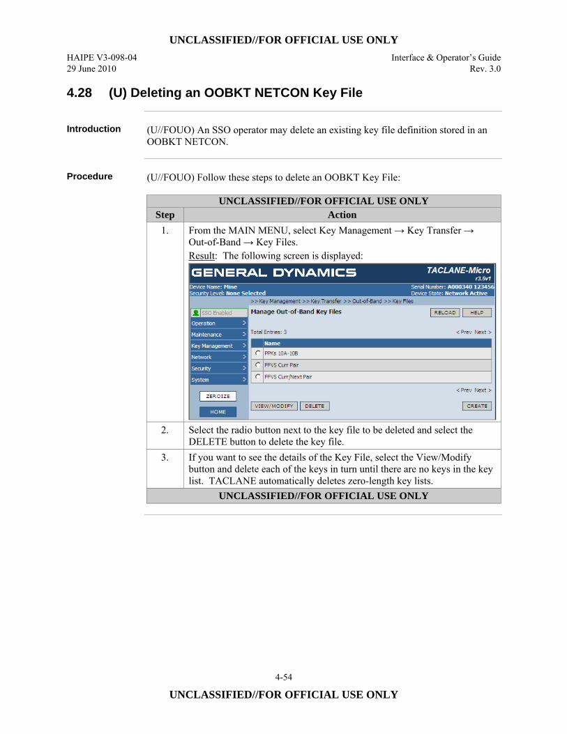
UNCLASSIFIED//FOR OFFICIAL USE ONLY HAIPE V3-098-04 Interface & Operator’s Guide 29 June 2010 Rev. 3.0
4-54
UNCLASSIFIED//FOR OFFICIAL USE ONLY
4.28 (U) Deleting an OOBKT NETCON Key File
Introduction (U//FOUO) An SSO operator may delete an existing key file definition stored in an
OOBKT NETCON.
Procedure (U//FOUO) Follow these steps to delete an OOBKT Key File:
UNCLASSIFIED//FOR OFFICIAL USE ONLY Step Action
1. From the MAIN MENU, select Key Management → Key Transfer → Out-of-Band → Key Files. Result: The following screen is displayed:
2. Select the radio button next to the key file to be deleted and select the DELETE button to delete the key file.
3. If you want to see the details of the Key File, select the View/Modify button and delete each of the keys in turn until there are no keys in the key list. TACLANE automatically deletes zero-length key lists.
UNCLASSIFIED//FOR OFFICIAL USE ONLY
UNCLASSIFIED//FOR OFFICIAL USE ONLY Interface & Operator’s Guide HAIPE V3-098-04 Rev. 3.0 29 June 2010
4-55
UNCLASSIFIED//FOR OFFICIAL USE ONLY
4.29 (U) Displaying OOBKT NETCON Client Transfers
Introduction (U//FOUO) An operator may view existing OOBKT Client Transfer definitions
stored in an OOBKT NETCON.
Notes (U//FOUO) An OOBKT Client Transfer definition includes an operator-assigned
Client Name, the Plain Text (PT) IP address for the named client, and the name of a key file that is a candidate for transfer to the OOBKT Client. (U//FOUO) When there are no OOBKT NETCON Client Transfer definitions, the ability of a TACLANE to act as an OOBKT NETCON is disabled. This is the default condition of the TACLANE. (U//FOUO) When at least one OOBKT NETCON Client transfer is defined, the TACLANE is enabled to act as an OOBKT NETCON.
Procedure (U//FOUO) Follow these steps to display the list OOBKT NETCON Client transfer
definitions defined for the TACLANE, and to view individual listed transfer client configurations.
Continued on next page
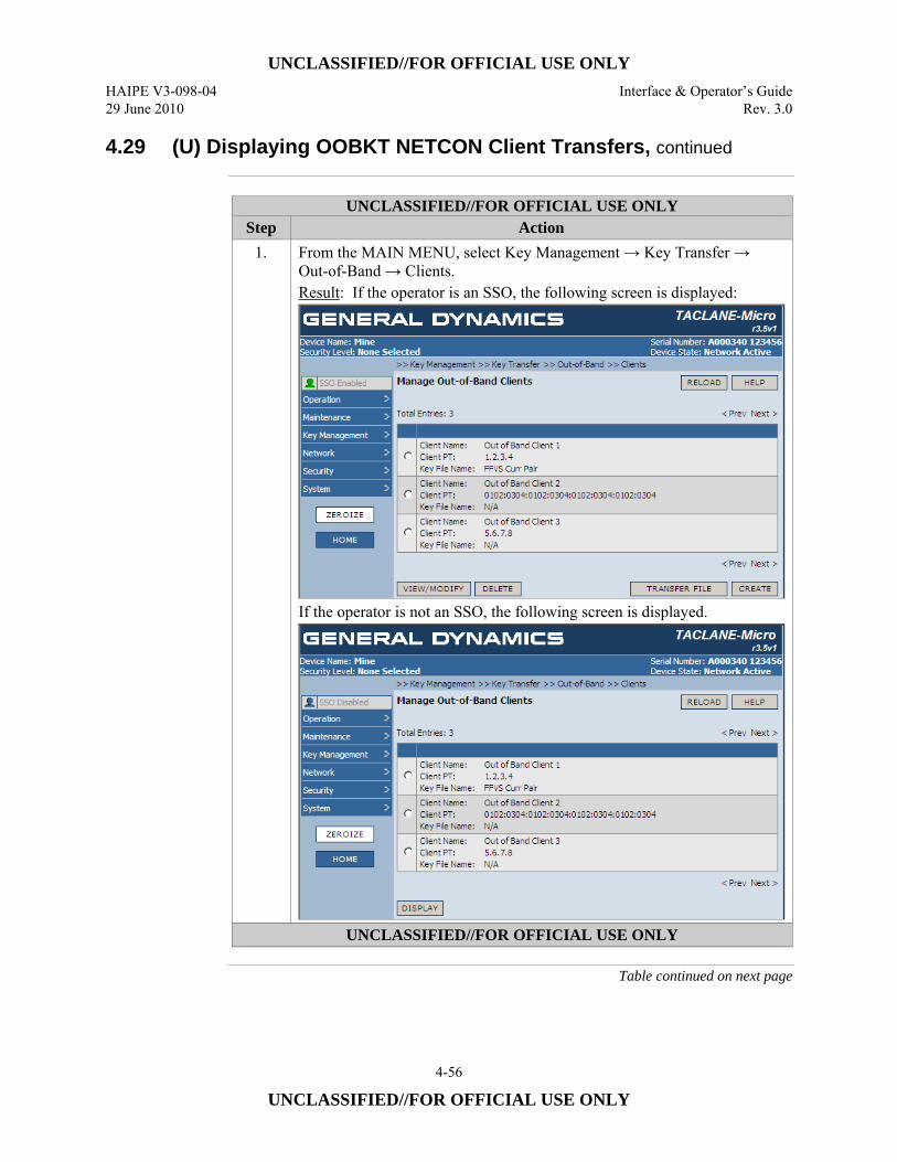
UNCLASSIFIED//FOR OFFICIAL USE ONLY HAIPE V3-098-04 Interface & Operator’s Guide 29 June 2010 Rev. 3.0
4-56
UNCLASSIFIED//FOR OFFICIAL USE ONLY
4.29 (U) Displaying OOBKT NETCON Client Transfers, continued
UNCLASSIFIED//FOR OFFICIAL USE ONLY
Step Action 1. From the MAIN MENU, select Key Management → Key Transfer →
Out-of-Band → Clients. Result: If the operator is an SSO, the following screen is displayed:
If the operator is not an SSO, the following screen is displayed.
UNCLASSIFIED//FOR OFFICIAL USE ONLY
Table continued on next page
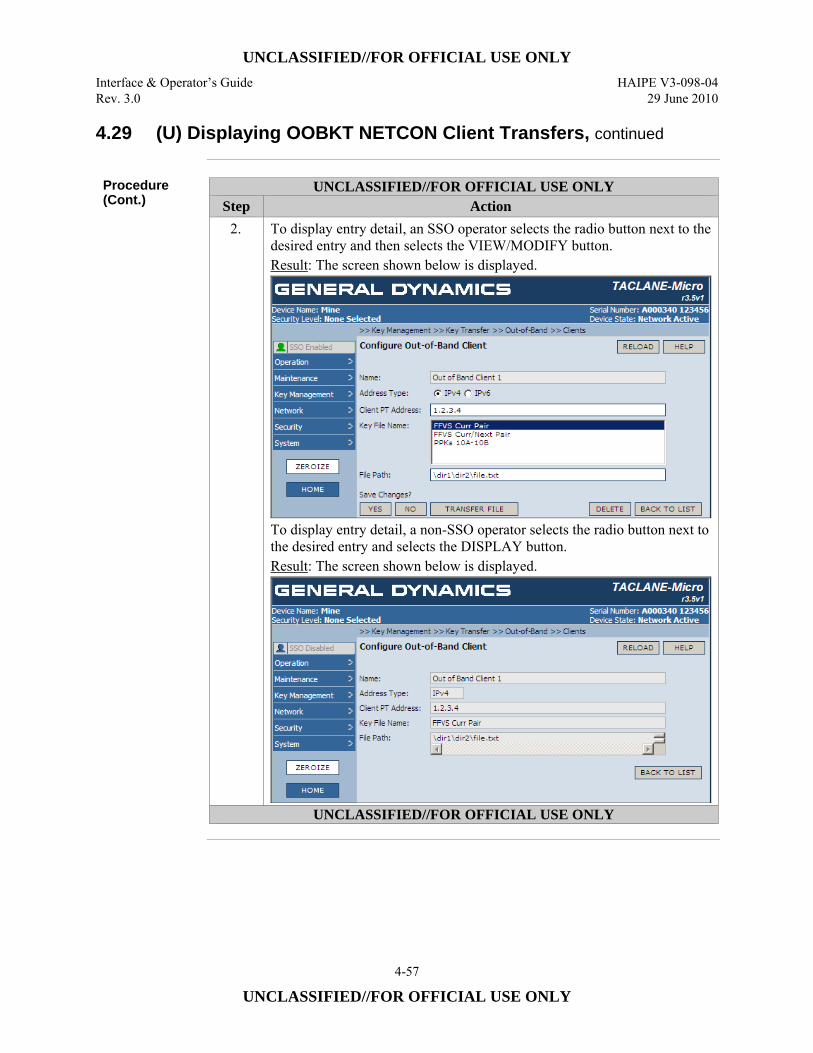
UNCLASSIFIED//FOR OFFICIAL USE ONLY Interface & Operator’s Guide HAIPE V3-098-04 Rev. 3.0 29 June 2010
4-57
UNCLASSIFIED//FOR OFFICIAL USE ONLY
4.29 (U) Displaying OOBKT NETCON Client Transfers, continued
Procedure (Cont.)
UNCLASSIFIED//FOR OFFICIAL USE ONLY Step Action
2. To display entry detail, an SSO operator selects the radio button next to the desired entry and then selects the VIEW/MODIFY button. Result: The screen shown below is displayed.
To display entry detail, a non-SSO operator selects the radio button next to the desired entry and selects the DISPLAY button. Result: The screen shown below is displayed.
UNCLASSIFIED//FOR OFFICIAL USE ONLY
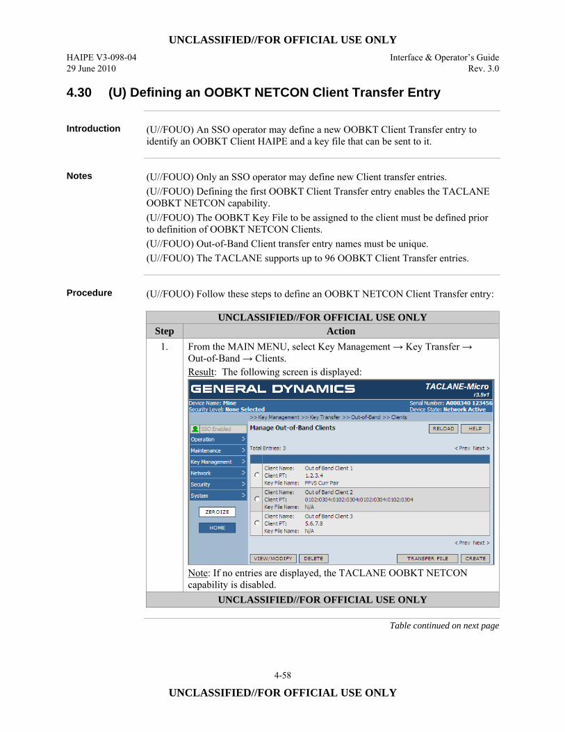
UNCLASSIFIED//FOR OFFICIAL USE ONLY HAIPE V3-098-04 Interface & Operator’s Guide 29 June 2010 Rev. 3.0
4-58
UNCLASSIFIED//FOR OFFICIAL USE ONLY
4.30 (U) Defining an OOBKT NETCON Client Transfer Entry
Introduction (U//FOUO) An SSO operator may define a new OOBKT Client Transfer entry to
identify an OOBKT Client HAIPE and a key file that can be sent to it.
Notes (U//FOUO) Only an SSO operator may define new Client transfer entries.
(U//FOUO) Defining the first OOBKT Client Transfer entry enables the TACLANE OOBKT NETCON capability. (U//FOUO) The OOBKT Key File to be assigned to the client must be defined prior to definition of OOBKT NETCON Clients. (U//FOUO) Out-of-Band Client transfer entry names must be unique. (U//FOUO) The TACLANE supports up to 96 OOBKT Client Transfer entries.
Procedure (U//FOUO) Follow these steps to define an OOBKT NETCON Client Transfer entry:
UNCLASSIFIED//FOR OFFICIAL USE ONLY Step Action
1. From the MAIN MENU, select Key Management → Key Transfer → Out-of-Band → Clients. Result: The following screen is displayed:
Note: If no entries are displayed, the TACLANE OOBKT NETCON capability is disabled.
UNCLASSIFIED//FOR OFFICIAL USE ONLY
Table continued on next page

UNCLASSIFIED//FOR OFFICIAL USE ONLY Interface & Operator’s Guide HAIPE V3-098-04 Rev. 3.0 29 June 2010
4-59
UNCLASSIFIED//FOR OFFICIAL USE ONLY
4.30 (U) Defining an OOBKT NETCON Client Transfer Entry, continued
Procedure (Cont.)
UNCLASSIFIED//FOR OFFICIAL USE ONLY Step Action
2. Select the CREATE button. Result: The following screen will be displayed.
Note: If no key files are listed, the operator will be unable to define an OOBKT Client entry.
3. Enter a name to identify this OOBKT Client transfer in the Name field. The name provided should be between 1 and 32 characters. Note: The name must be different than other Client names, if any
4. Identify the type of Client address (i.e., IPv4 or IPv6) by selecting the applicable Address Type radio button.
5. Enter the PT IP address of the target OOBKT Client in the Client PT Address field.
6. Select the key file that will be sent to the OOBKT Client from the list provided in the Key File Name window. Note: An OOBKT NETCON Key File must have been created before an OOBKT Client entry can be defined. An OOBKT NETCON Client Transfer Entry cannot be created, if there is no key file.
UNCLASSIFIED//FOR OFFICIAL USE ONLY
Table continued on next page
UNCLASSIFIED//FOR OFFICIAL USE ONLY HAIPE V3-098-04 Interface & Operator’s Guide 29 June 2010 Rev. 3.0
4-60
UNCLASSIFIED//FOR OFFICIAL USE ONLY
4.30 (U) Defining an OOBKT NETCON Client Transfer Entry, continued
Procedure (Cont.)
UNCLASSIFIED//FOR OFFICIAL USE ONLY Step Action
7. If desired, provide a File Path name for the key file to be provided to the named OOBKT Client. The file path name may be up to 256 characters in length. It may be empty, if desired. Character input should be restricted to printable characters from the extended (i.e., 8-bit) ASCII set. The following characters should not be used in a file path name. % – Percent sign & – Ampersand ‘ – Single quote ( – Open parenthesis ) – Close parenthesis * – Asterisk , – Comma < – Open angle bracket = – Equal sign > – Close angle bracket @ – At symbol [ – Open bracket ] – Close bracket ^ – Caret circumflex { – Open brace } – Close brace
File path names containing any of the characters above will be rejected. Note: Some OOBKT Clients may require a specific file path name to properly process a received OOBKT file. A TACLANE OOBKT Client does not require a file path name entry. If provided, the TACLANE uses it to identify a received OOBKT file in logs and notifications.
8. Select the YES button under the Save Changes choices to save the defined OOBKT Client transfer entry.
UNCLASSIFIED//FOR OFFICIAL USE ONLY
UNCLASSIFIED//FOR OFFICIAL USE ONLY Interface & Operator’s Guide HAIPE V3-098-04 Rev. 3.0 29 June 2010
4-61
UNCLASSIFIED//FOR OFFICIAL USE ONLY
4.31 (U) Initiating an OOBKT NETCON Transfer to a Client
Introduction (U//FOUO) An SSO operator may initiate the transfer of an identified Key File to an
OOBKT client using a previously saved OOBKT NETCON Client Transfer entry or initiate the transfer immediately after completing such an entry.
Notes (U//FOUO) Only an SSO operator may initiate OOBKT to an OOBKT Client.
(U//FOUO) At least one OOBKT Key File must be defined to initiate an Out-of-Band Key Transfer to an OOBKT Client. (U//FOUO) An OOBKT Client Transfer entry must have been defined prior to initiation of OOBKT to an OOBKT Client.
OOBKT Message Transmission Indications
(U//FOUO) If an SSO operator attempts to initiate an OOBKT NETCON Transfer and the Client Transfer entry is invalid (e.g., an identified key file is missing), the attempt will be rejected and an immediate indication of the reason will be provided through the HMI screen. (U//FOUO) After an operator action to initiate an OOBKT Transfer is accepted, the TACLANE will provide a notification and a security audit log entry when the outgoing transfer is completed successfully or unsuccessfully.
Procedure (U//FOUO) Follow these steps to initiate an OOBKT NETCON Client Transfer
entry:
Continued on next page
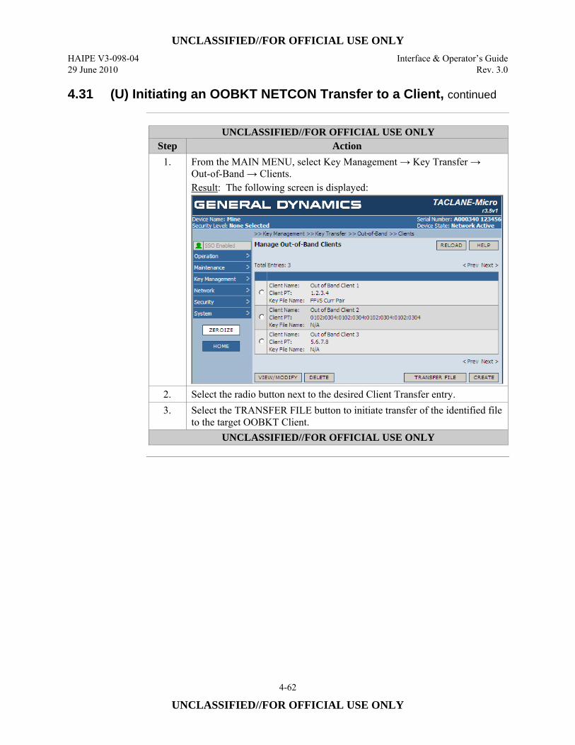
UNCLASSIFIED//FOR OFFICIAL USE ONLY HAIPE V3-098-04 Interface & Operator’s Guide 29 June 2010 Rev. 3.0
4-62
UNCLASSIFIED//FOR OFFICIAL USE ONLY
4.31 (U) Initiating an OOBKT NETCON Transfer to a Client, continued
UNCLASSIFIED//FOR OFFICIAL USE ONLY
Step Action 1. From the MAIN MENU, select Key Management → Key Transfer →
Out-of-Band → Clients. Result: The following screen is displayed:
2. Select the radio button next to the desired Client Transfer entry. 3. Select the TRANSFER FILE button to initiate transfer of the identified file
to the target OOBKT Client. UNCLASSIFIED//FOR OFFICIAL USE ONLY
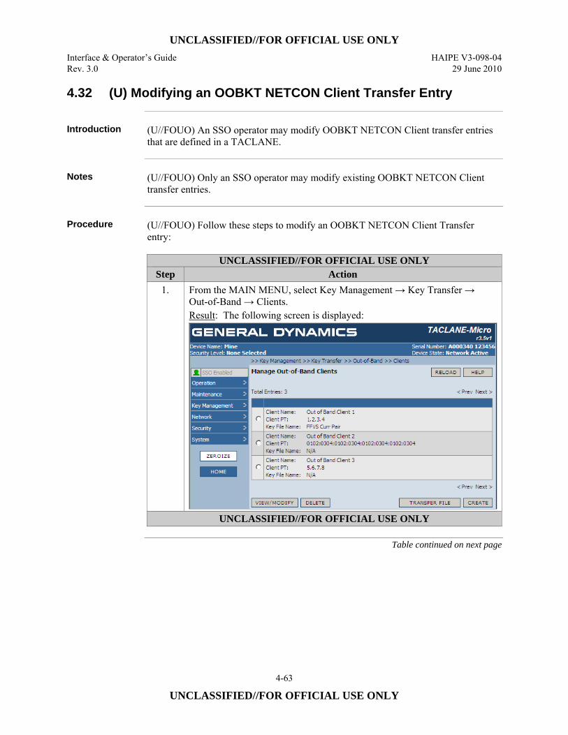
UNCLASSIFIED//FOR OFFICIAL USE ONLY Interface & Operator’s Guide HAIPE V3-098-04 Rev. 3.0 29 June 2010
4-63
UNCLASSIFIED//FOR OFFICIAL USE ONLY
4.32 (U) Modifying an OOBKT NETCON Client Transfer Entry
Introduction (U//FOUO) An SSO operator may modify OOBKT NETCON Client transfer entries
that are defined in a TACLANE.
Notes (U//FOUO) Only an SSO operator may modify existing OOBKT NETCON Client
transfer entries.
Procedure (U//FOUO) Follow these steps to modify an OOBKT NETCON Client Transfer
entry:
UNCLASSIFIED//FOR OFFICIAL USE ONLY Step Action
1. From the MAIN MENU, select Key Management → Key Transfer → Out-of-Band → Clients. Result: The following screen is displayed:
UNCLASSIFIED//FOR OFFICIAL USE ONLY
Table continued on next page
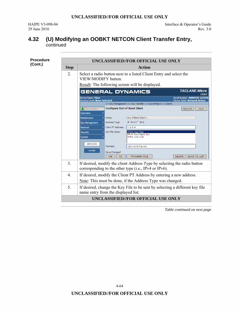
UNCLASSIFIED//FOR OFFICIAL USE ONLY HAIPE V3-098-04 Interface & Operator’s Guide 29 June 2010 Rev. 3.0
4-64
UNCLASSIFIED//FOR OFFICIAL USE ONLY
4.32 (U) Modifying an OOBKT NETCON Client Transfer Entry, continued
Procedure (Cont.)
UNCLASSIFIED//FOR OFFICIAL USE ONLY Step Action
2. Select a radio button next to a listed Client Entry and select the VIEW/MODIFY button. Result: The following screen will be displayed.
3. If desired, modify the client Address Type by selecting the radio button corresponding to the other type (i.e., IPv4 or IPv6).
4. If desired, modify the Client PT Address by entering a new address. Note: This must be done, if the Address Type was changed.
5. If desired, change the Key File to be sent by selecting a different key file name entry from the displayed list.
UNCLASSIFIED//FOR OFFICIAL USE ONLY
Table continued on next page
UNCLASSIFIED//FOR OFFICIAL USE ONLY Interface & Operator’s Guide HAIPE V3-098-04 Rev. 3.0 29 June 2010
4-65
UNCLASSIFIED//FOR OFFICIAL USE ONLY
4.32 (U) Modifying an OOBKT NETCON Client Transfer Entry, continued
Procedure (Cont.)
UNCLASSIFIED//FOR OFFICIAL USE ONLY Step Action
6. If desired, modify the file path by editing the content of the File Path field providing a path name from 0 up to 256 characters. Character input should be restricted to printable characters from the extended (i.e., 8-bit) ASCII set. The following characters should not be used in a file path name. % – Percent sign & – Ampersand ‘ – Single quote ( – Open parenthesis ) – Close parenthesis * – Asterisk , – Comma < – Open angle bracket = – Equal sign > – Close angle bracket @ – At symbol [ – Open bracket ] – Close bracket ^ – Caret circumflex { – Open brace } – Close brace
File path names containing any of the characters above will be rejected. Note: Some OOBKT Clients may require a specific file path name to properly process a received OOBKT file. A TACLANE OOBKT Client does not require a file path name entry. If provided, the TACLANE uses it to identify a received OOBKT file in logs and notifications.
7. Select the YES button option under the Save Changes label to save the changes made.
UNCLASSIFIED//FOR OFFICIAL USE ONLY
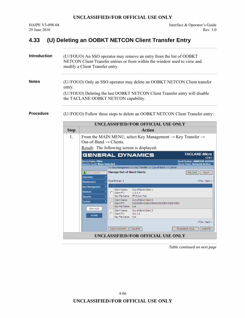
UNCLASSIFIED//FOR OFFICIAL USE ONLY HAIPE V3-098-04 Interface & Operator’s Guide 29 June 2010 Rev. 3.0
4-66
UNCLASSIFIED//FOR OFFICIAL USE ONLY
4.33 (U) Deleting an OOBKT NETCON Client Transfer Entry
Introduction (U//FOUO) An SSO operator may remove an entry from the list of OOBKT
NETCON Client Transfer entries or from within the window used to view and modify a Client Transfer entry.
Notes (U//FOUO) Only an SSO operator may delete an OOBKT NETCON Client transfer
entry. (U//FOUO) Deleting the last OOBKT NETCON Client Transfer entry will disable the TACLANE OOBKT NETCON capability.
Procedure (U//FOUO) Follow these steps to delete an OOBKT NETCON Client Transfer entry:
UNCLASSIFIED//FOR OFFICIAL USE ONLY Step Action
1. From the MAIN MENU, select Key Management → Key Transfer → Out-of-Band → Clients. Result: The following screen is displayed:
UNCLASSIFIED//FOR OFFICIAL USE ONLY
Table continued on next page
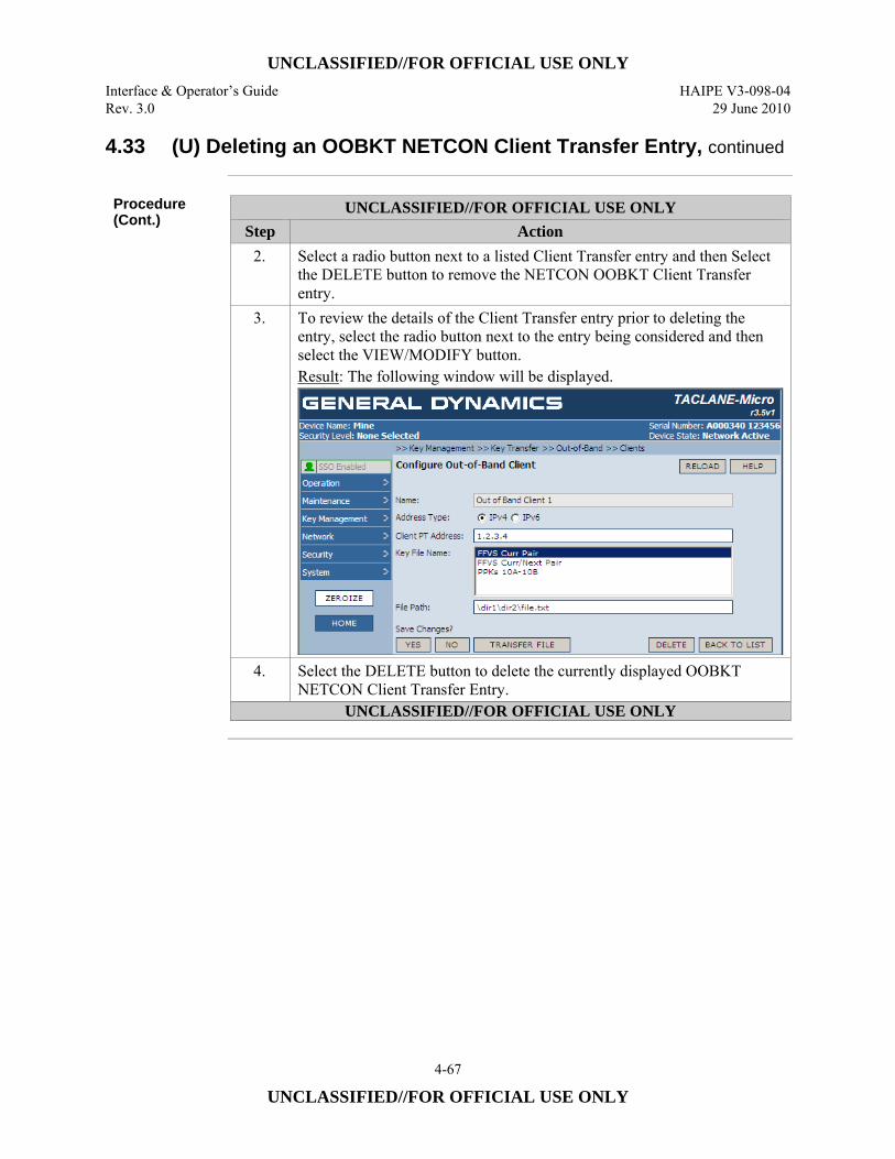
UNCLASSIFIED//FOR OFFICIAL USE ONLY Interface & Operator’s Guide HAIPE V3-098-04 Rev. 3.0 29 June 2010
4-67
UNCLASSIFIED//FOR OFFICIAL USE ONLY
4.33 (U) Deleting an OOBKT NETCON Client Transfer Entry, continued
Procedure (Cont.)
UNCLASSIFIED//FOR OFFICIAL USE ONLY Step Action
2. Select a radio button next to a listed Client Transfer entry and then Select the DELETE button to remove the NETCON OOBKT Client Transfer entry.
3. To review the details of the Client Transfer entry prior to deleting the entry, select the radio button next to the entry being considered and then select the VIEW/MODIFY button. Result: The following window will be displayed.
4. Select the DELETE button to delete the currently displayed OOBKT NETCON Client Transfer Entry.
UNCLASSIFIED//FOR OFFICIAL USE ONLY
UNCLASSIFIED//FOR OFFICIAL USE ONLY HAIPE V3-098-04 Interface & Operator’s Guide 29 June 2010 Rev. 3.0
4-68
UNCLASSIFIED//FOR OFFICIAL USE ONLY
4.34 (U) Displaying OOBKT Client Authorized Controllers
Introduction (U//FOUO) An operator may display the list of authorized controllers for an OOBKT
Client.
Notes (U//FOUO) When there are no OOBKT Client authorized controllers, the ability of
the TACLANE to act in the role of an OOBKT Client is disabled. This is the default condition of the TACLANE. (U//FOUO) When one or more authorized controllers are defined for an OOBKT Client, the TACLANE is enabled to act as an OOBKT Client.
Procedure (U//FOUO) Follow these steps to display an OOBKT Client’s authorized controllers:
Continued on next page
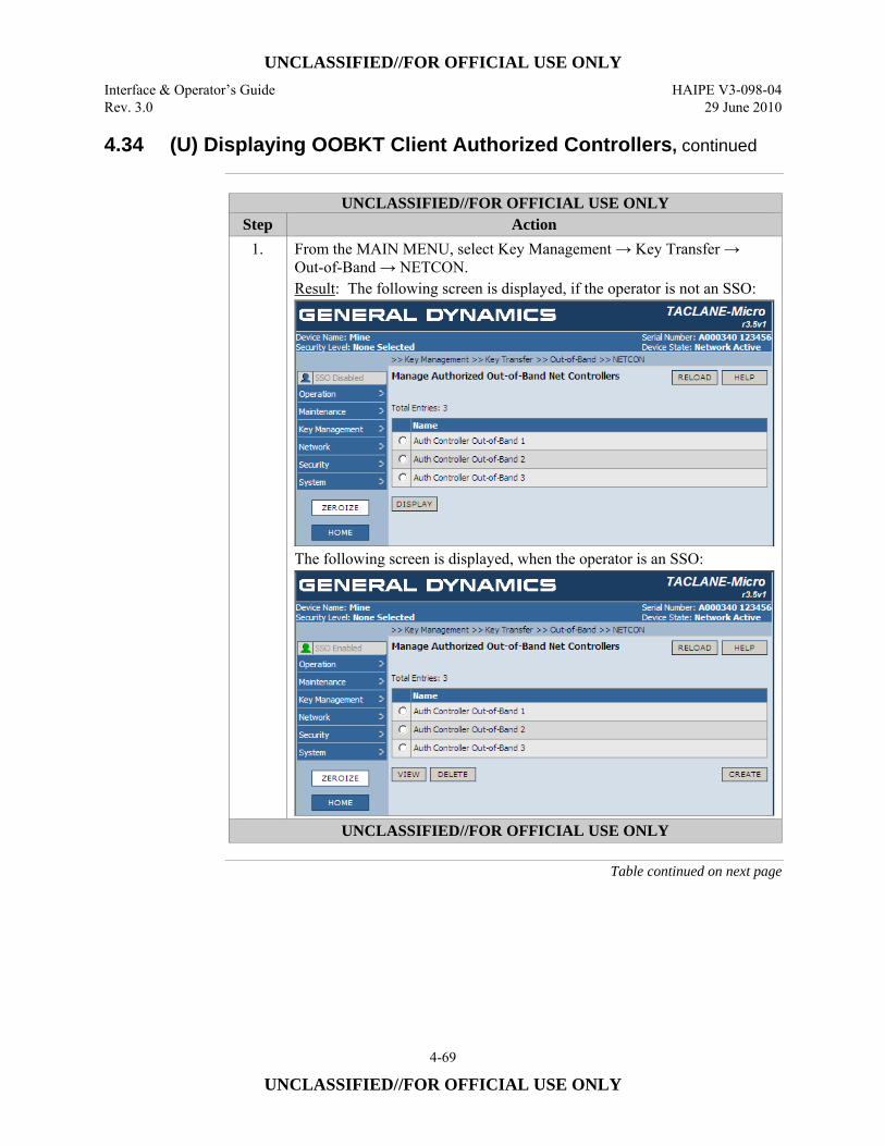
UNCLASSIFIED//FOR OFFICIAL USE ONLY Interface & Operator’s Guide HAIPE V3-098-04 Rev. 3.0 29 June 2010
4-69
UNCLASSIFIED//FOR OFFICIAL USE ONLY
4.34 (U) Displaying OOBKT Client Authorized Controllers, continued
UNCLASSIFIED//FOR OFFICIAL USE ONLY
Step Action 1. From the MAIN MENU, select Key Management → Key Transfer →
Out-of-Band → NETCON. Result: The following screen is displayed, if the operator is not an SSO:
The following screen is displayed, when the operator is an SSO:
UNCLASSIFIED//FOR OFFICIAL USE ONLY
Table continued on next page
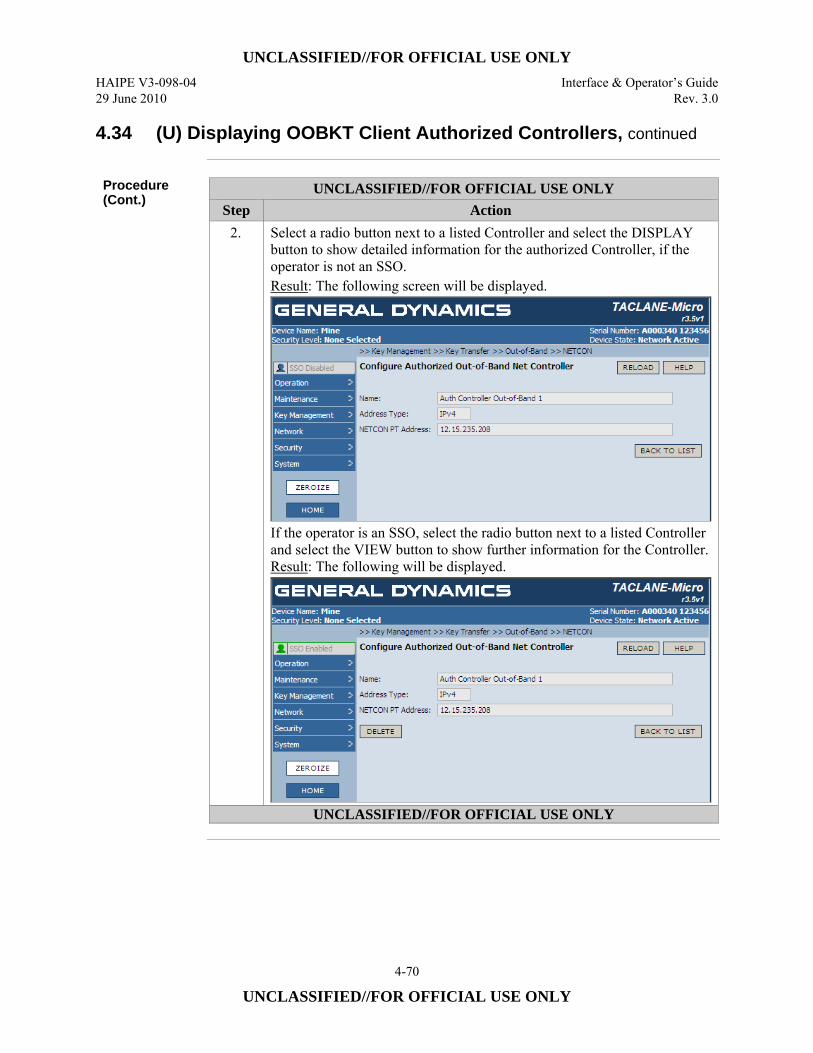
UNCLASSIFIED//FOR OFFICIAL USE ONLY HAIPE V3-098-04 Interface & Operator’s Guide 29 June 2010 Rev. 3.0
4-70
UNCLASSIFIED//FOR OFFICIAL USE ONLY
4.34 (U) Displaying OOBKT Client Authorized Controllers, continued
Procedure (Cont.)
UNCLASSIFIED//FOR OFFICIAL USE ONLY Step Action
2. Select a radio button next to a listed Controller and select the DISPLAY button to show detailed information for the authorized Controller, if the operator is not an SSO. Result: The following screen will be displayed.
If the operator is an SSO, select the radio button next to a listed Controller and select the VIEW button to show further information for the Controller. Result: The following will be displayed.
UNCLASSIFIED//FOR OFFICIAL USE ONLY
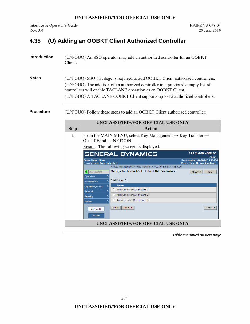
UNCLASSIFIED//FOR OFFICIAL USE ONLY Interface & Operator’s Guide HAIPE V3-098-04 Rev. 3.0 29 June 2010
4-71
UNCLASSIFIED//FOR OFFICIAL USE ONLY
4.35 (U) Adding an OOBKT Client Authorized Controller
Introduction (U//FOUO) An SSO operator may add an authorized controller for an OOBKT
Client.
Notes (U//FOUO) SSO privilege is required to add OOBKT Client authorized controllers.
(U//FOUO) The addition of an authorized controller to a previously empty list of controllers will enable TACLANE operation as an OOBKT Client. (U//FOUO) A TACLANE OOBKT Client supports up to 12 authorized controllers.
Procedure (U//FOUO) Follow these steps to add an OOBKT Client authorized controller:
UNCLASSIFIED//FOR OFFICIAL USE ONLY Step Action
1. From the MAIN MENU, select Key Management → Key Transfer → Out-of-Band → NETCON. Result: The following screen is displayed:
UNCLASSIFIED//FOR OFFICIAL USE ONLY
Table continued on next page
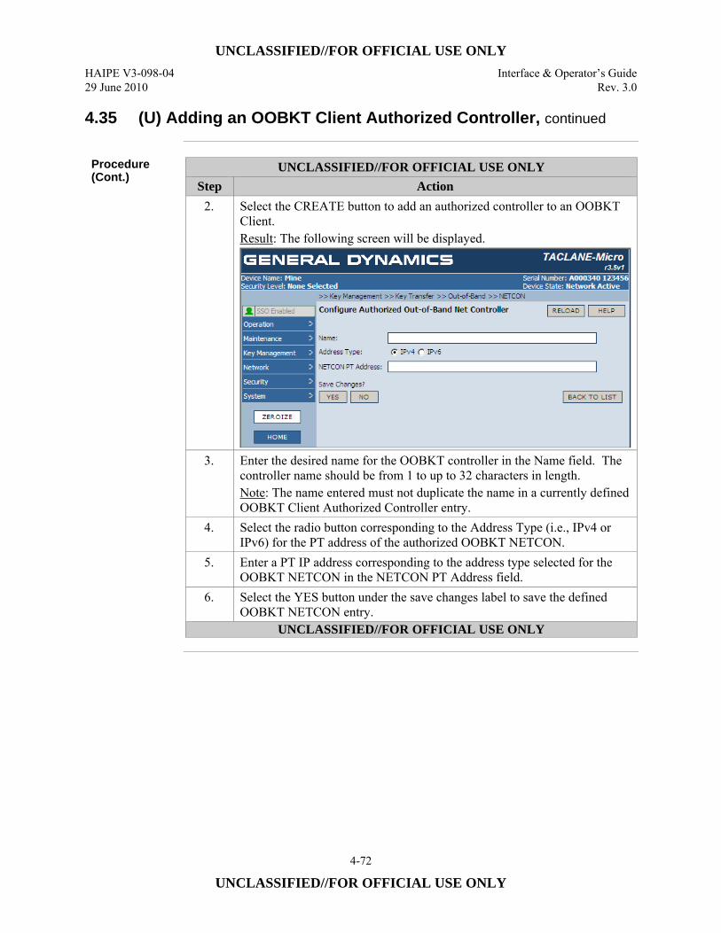
UNCLASSIFIED//FOR OFFICIAL USE ONLY HAIPE V3-098-04 Interface & Operator’s Guide 29 June 2010 Rev. 3.0
4-72
UNCLASSIFIED//FOR OFFICIAL USE ONLY
4.35 (U) Adding an OOBKT Client Authorized Controller, continued
Procedure (Cont.)
UNCLASSIFIED//FOR OFFICIAL USE ONLY Step Action
2. Select the CREATE button to add an authorized controller to an OOBKT Client. Result: The following screen will be displayed.
3. Enter the desired name for the OOBKT controller in the Name field. The controller name should be from 1 to up to 32 characters in length. Note: The name entered must not duplicate the name in a currently defined OOBKT Client Authorized Controller entry.
4. Select the radio button corresponding to the Address Type (i.e., IPv4 or IPv6) for the PT address of the authorized OOBKT NETCON.
5. Enter a PT IP address corresponding to the address type selected for the OOBKT NETCON in the NETCON PT Address field.
6. Select the YES button under the save changes label to save the defined OOBKT NETCON entry.
UNCLASSIFIED//FOR OFFICIAL USE ONLY
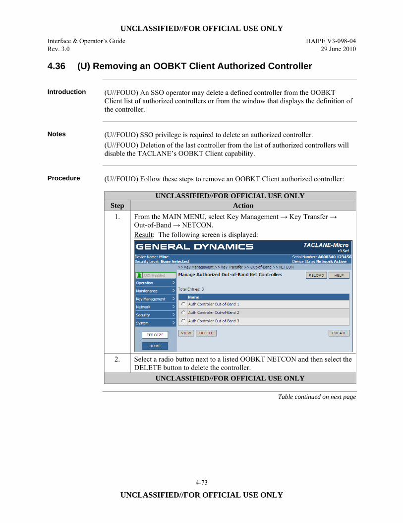
UNCLASSIFIED//FOR OFFICIAL USE ONLY Interface & Operator’s Guide HAIPE V3-098-04 Rev. 3.0 29 June 2010
4-73
UNCLASSIFIED//FOR OFFICIAL USE ONLY
4.36 (U) Removing an OOBKT Client Authorized Controller
Introduction (U//FOUO) An SSO operator may delete a defined controller from the OOBKT
Client list of authorized controllers or from the window that displays the definition of the controller.
Notes (U//FOUO) SSO privilege is required to delete an authorized controller.
(U//FOUO) Deletion of the last controller from the list of authorized controllers will disable the TACLANE’s OOBKT Client capability.
Procedure (U//FOUO) Follow these steps to remove an OOBKT Client authorized controller:
UNCLASSIFIED//FOR OFFICIAL USE ONLY Step Action
1. From the MAIN MENU, select Key Management → Key Transfer → Out-of-Band → NETCON. Result: The following screen is displayed:
2. Select a radio button next to a listed OOBKT NETCON and then select the DELETE button to delete the controller.
UNCLASSIFIED//FOR OFFICIAL USE ONLY
Table continued on next page
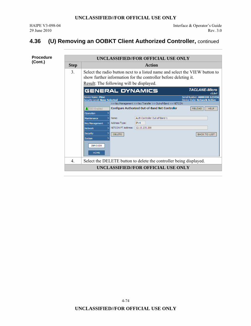
UNCLASSIFIED//FOR OFFICIAL USE ONLY HAIPE V3-098-04 Interface & Operator’s Guide 29 June 2010 Rev. 3.0
4-74
UNCLASSIFIED//FOR OFFICIAL USE ONLY
4.36 (U) Removing an OOBKT Client Authorized Controller, continued
Procedure (Cont.)
UNCLASSIFIED//FOR OFFICIAL USE ONLY Step Action
3. Select the radio button next to a listed name and select the VIEW button to show further information for the controller before deleting it. Result: The following will be displayed.
4. Select the DELETE button to delete the controller being displayed. UNCLASSIFIED//FOR OFFICIAL USE ONLY
UNCLASSIFIED//FOR OFFICIAL USE ONLY Interface & Operator’s Guide HAIPE V3-098-04 Rev. 3.0 29 June 2010
4-75
UNCLASSIFIED//FOR OFFICIAL USE ONLY
4.37 (U) Displaying IBKT NETCON Client Transfers
Introduction (U//FOUO) An operator may display a list of a TACLANE IBKT NETCON’s
scheduled transfers for IBKT clients.
Notes (U//FOUO) The TACLANE supports up to 240 Client Transfer entries.
(U//FOUO) If no Client Transfer entries are defined, the IBKT NETCON capability of the TACLANE is disabled. This is the default condition of the TACLANE. (U//FOUO) When one or more Client Transfer entries are listed, the TACLANE is enabled as an IBKT NETCON.
Procedure (U//FOUO) Follow these steps to display scheduled IBKT NETCON Client
Transfers:
Continued on next page
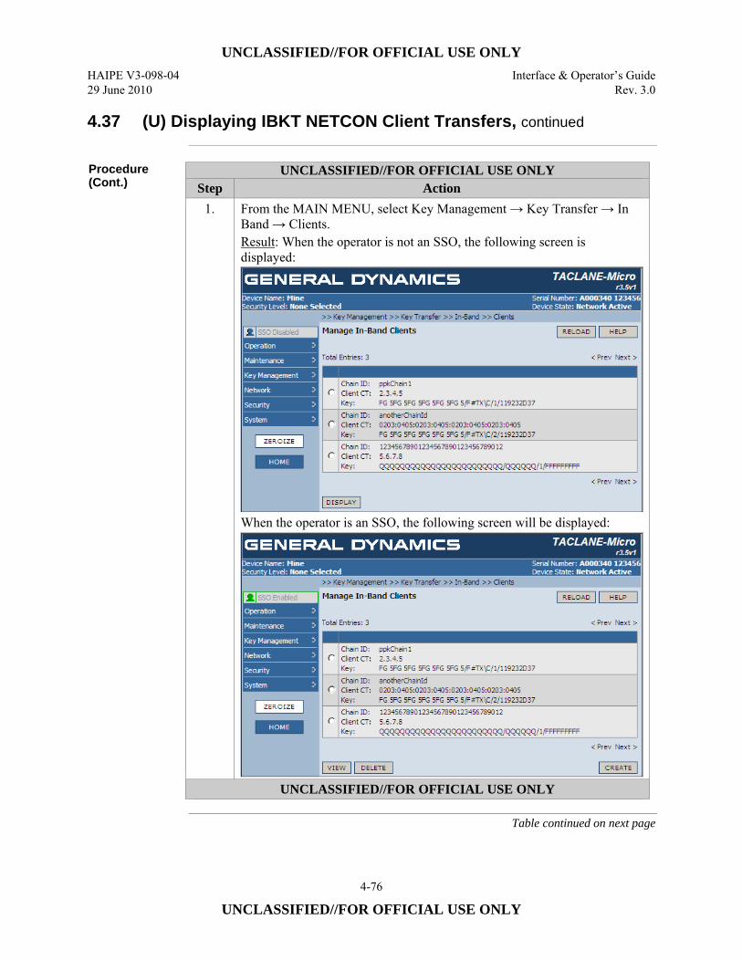
UNCLASSIFIED//FOR OFFICIAL USE ONLY HAIPE V3-098-04 Interface & Operator’s Guide 29 June 2010 Rev. 3.0
4-76
UNCLASSIFIED//FOR OFFICIAL USE ONLY
4.37 (U) Displaying IBKT NETCON Client Transfers, continued
Procedure (Cont.)
UNCLASSIFIED//FOR OFFICIAL USE ONLY Step Action
1. From the MAIN MENU, select Key Management → Key Transfer → In Band → Clients. Result: When the operator is not an SSO, the following screen is displayed:
When the operator is an SSO, the following screen will be displayed:
UNCLASSIFIED//FOR OFFICIAL USE ONLY
Table continued on next page
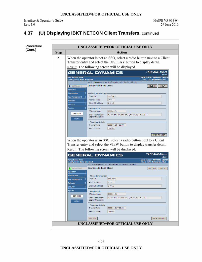
UNCLASSIFIED//FOR OFFICIAL USE ONLY Interface & Operator’s Guide HAIPE V3-098-04 Rev. 3.0 29 June 2010
4-77
UNCLASSIFIED//FOR OFFICIAL USE ONLY
4.37 (U) Displaying IBKT NETCON Client Transfers, continued
Procedure (Cont.)
UNCLASSIFIED//FOR OFFICIAL USE ONLY Step Action
2. When the operator is not an SSO, select a radio button next to a Client Transfer entry and select the DISPLAY button to display detail. Result: The following screen will be displayed.
When the operator is an SSO, select a radio button next to a Client Transfer entry and select the VIEW button to display transfer detail. Result: The following screen will be displayed.
UNCLASSIFIED//FOR OFFICIAL USE ONLY
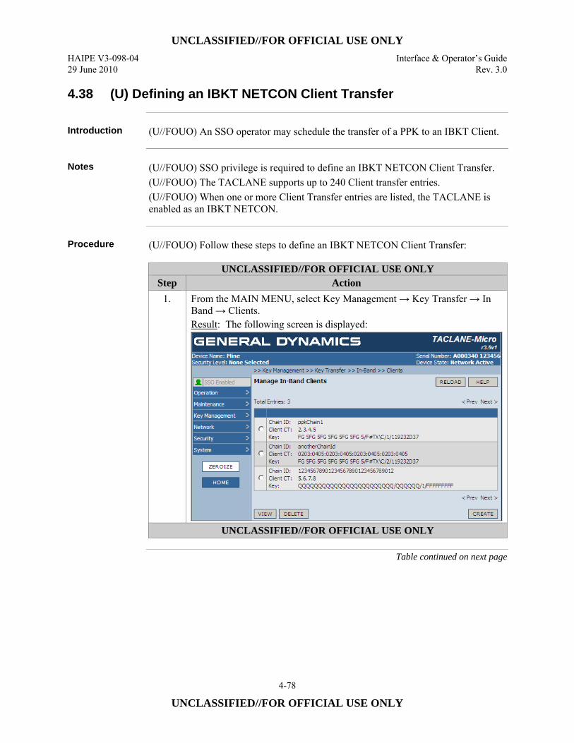
UNCLASSIFIED//FOR OFFICIAL USE ONLY HAIPE V3-098-04 Interface & Operator’s Guide 29 June 2010 Rev. 3.0
4-78
UNCLASSIFIED//FOR OFFICIAL USE ONLY
4.38 (U) Defining an IBKT NETCON Client Transfer
Introduction (U//FOUO) An SSO operator may schedule the transfer of a PPK to an IBKT Client.
Notes (U//FOUO) SSO privilege is required to define an IBKT NETCON Client Transfer.
(U//FOUO) The TACLANE supports up to 240 Client transfer entries. (U//FOUO) When one or more Client Transfer entries are listed, the TACLANE is enabled as an IBKT NETCON.
Procedure (U//FOUO) Follow these steps to define an IBKT NETCON Client Transfer:
UNCLASSIFIED//FOR OFFICIAL USE ONLY Step Action
1. From the MAIN MENU, select Key Management → Key Transfer → In Band → Clients. Result: The following screen is displayed:
UNCLASSIFIED//FOR OFFICIAL USE ONLY
Table continued on next page

UNCLASSIFIED//FOR OFFICIAL USE ONLY Interface & Operator’s Guide HAIPE V3-098-04 Rev. 3.0 29 June 2010
4-79
UNCLASSIFIED//FOR OFFICIAL USE ONLY
4.38 (U) Defining an IBKT NETCON Client Transfer, continued
Procedure (Cont.)
UNCLASSIFIED//FOR OFFICIAL USE ONLY Step Action
2. Select the CREATE button. Result: The following screen will be displayed.
Note: The Chain IDs displayed depend on the currently defined complement of Traffic PPK chains defined for the TACLANE. The list of keys shown depends on the issue-formatted PPKs currently stored in the TACLANE that are compatible with the selected PPK chain in terms of classification security level and cryptographic suite (i.e., Suite A or B).
3. Select a Key Chain ID from the list of TACLANE Traffic PPK chains in the Chain ID window.
4. Select the radio button corresponding to the Address Type (i.e., IPv4 or IPv6) of the IBKT Client that is the intended recipient of the transfer.
UNCLASSIFIED//FOR OFFICIAL USE ONLY
Table continued on next page
UNCLASSIFIED//FOR OFFICIAL USE ONLY HAIPE V3-098-04 Interface & Operator’s Guide 29 June 2010 Rev. 3.0
4-80
UNCLASSIFIED//FOR OFFICIAL USE ONLY
4.38 (U) Defining an IBKT NETCON Client Transfer, continued
Procedure (Cont.)
UNCLASSIFIED//FOR OFFICIAL USE ONLY Step Action
5. Enter the IBKT client’s CT IP address of the type previously selected in the Client CT Address field. Note: The previously identified Traffic PPK chain must support an outgoing Security Association to CT IP address provided.
6. Enter an effective date to be assigned to the transferred key as a year and month. Note: All keys are effective on the first day of a month. The month and year can be for the current calendar month or a calendar month up to 11 months in the future. Months outside this range will be rejected.
7. Select the PPK to be transferred from the list of PPKs shown in the window under key details.
8. Define the time and date for the first transfer of the key. The date and time are entered as year, month, day, hour and minute. Note:
• The date and time entered should be a future time for the current month or a month up to 11 months in the future, but not beyond the effective month of the PPK to be transferred.
• If more than one IBKT Client Transfer is configured for a PPK Key, the effective date for that key must be the same in all IBKT Client Transfer entries.
• If the key being transferred is effective tomorrow in the current or next calendar month, the operator should not specify a time between 22:05 GMT and 01:55 GMT. IBKT NETCON message transfers of an effective key are prohibited during this window.
UNCLASSIFIED//FOR OFFICIAL USE ONLY
Table continued on next page
UNCLASSIFIED//FOR OFFICIAL USE ONLY Interface & Operator’s Guide HAIPE V3-098-04 Rev. 3.0 29 June 2010
4-81
UNCLASSIFIED//FOR OFFICIAL USE ONLY
4.38 (U) Defining an IBKT NETCON Client Transfer, continued
Procedure (Cont.)
UNCLASSIFIED//FOR OFFICIAL USE ONLY Step Action
9. If additional transfer attempts are desired, select the Retry Transfer box and then enter the number of retries desired in the Retries field and the number of seconds between retries in the Retry Period field. Note: TACLANE stops IBKT of a key after all scheduled retries are attempted or on or after the key’s last effective day, whichever comes first. Note: The number of retries and the retry period can be in the range 1 to 31,622,401. This range accommodates scheduling a retry every second for a year or a single retry up to 12 months after the first transfer. Note: Avoid scheduling an excessive number of retries and retries that occur more often than necessary. This may degrade system performance. The following information may be useful in scheduling retries: Seconds → Period Seconds → Period Seconds → Period 60 → 1 minute 3,600 → 1 hour 86,400 → 1 day 300 → 5 minutes 14,400 → 4 hours 172,800 → 2 days 900 → 15 minutes 21,600 → 6 hours 604,800 → 7 days 1,800 → 30 minutes 43,200 → 12 hours 2,592,000 → 30 days
Note: When transferring and superseding a current month PPK, all IBKT attempts should be scheduled for the same day, if possible. This ensures the OOBKT NETCON and OOBKT Clients that receive the PPK will be operating with the same key the next day. Representative IBKT schedules to accomplish this before 22:05 GMT are provided below. Transfer Time − Retries − Period Transfer Time − Retries − Period 01:56 − 10 − 7,248 15:00 − 10 − 2,544 01:56 − 100 − 724 15:00 − 100 − 254 03:00 − 10 − 6,864 18:00 − 10 − 1,464 03:00 − 100 − 686 18:00 − 100 − 146 06:00 − 10 − 5,784 21:00 − 10 − 384 06:00 − 100 − 578 21:00 − 100 − 38 09:00 − 10 − 4,704 21:30 − 10 − 204 09:00 − 100 − 470 21:30 − 100 − 20 12:00 − 10 − 3,624 22:00 − 10 − 24 12:00 − 100 − 362 22:00 − 100 − 2 An earlier upcoming time value that is not earlier than 01:56 GMT may be substituted for one of the sample Transfer Times above with the same associated Retries and Period values.
10. Select the YES button under Save Changes to save the Client Transfer entry.
UNCLASSIFIED//FOR OFFICIAL USE ONLY
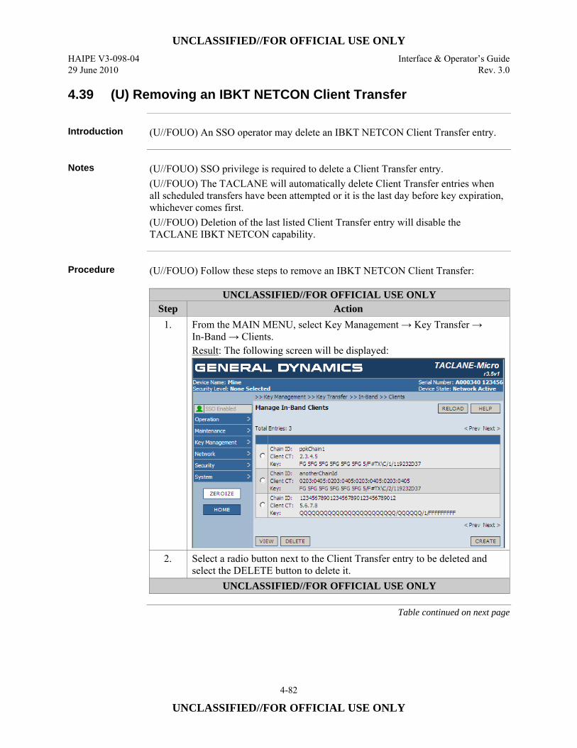
UNCLASSIFIED//FOR OFFICIAL USE ONLY HAIPE V3-098-04 Interface & Operator’s Guide 29 June 2010 Rev. 3.0
4-82
UNCLASSIFIED//FOR OFFICIAL USE ONLY
4.39 (U) Removing an IBKT NETCON Client Transfer
Introduction (U//FOUO) An SSO operator may delete an IBKT NETCON Client Transfer entry.
Notes (U//FOUO) SSO privilege is required to delete a Client Transfer entry.
(U//FOUO) The TACLANE will automatically delete Client Transfer entries when all scheduled transfers have been attempted or it is the last day before key expiration, whichever comes first. (U//FOUO) Deletion of the last listed Client Transfer entry will disable the TACLANE IBKT NETCON capability.
Procedure (U//FOUO) Follow these steps to remove an IBKT NETCON Client Transfer:
UNCLASSIFIED//FOR OFFICIAL USE ONLY Step Action
1. From the MAIN MENU, select Key Management → Key Transfer → In-Band → Clients. Result: The following screen will be displayed:
2. Select a radio button next to the Client Transfer entry to be deleted and select the DELETE button to delete it.
UNCLASSIFIED//FOR OFFICIAL USE ONLY
Table continued on next page
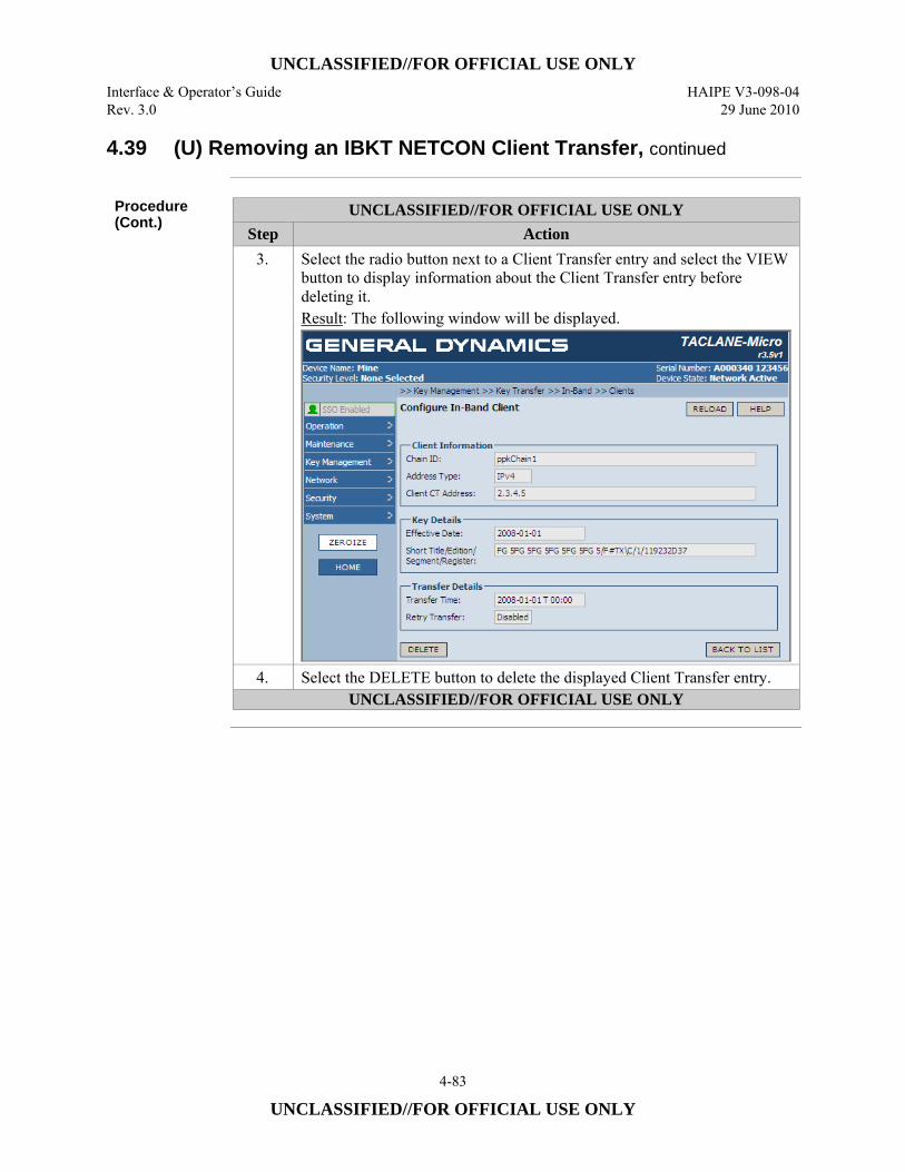
UNCLASSIFIED//FOR OFFICIAL USE ONLY Interface & Operator’s Guide HAIPE V3-098-04 Rev. 3.0 29 June 2010
4-83
UNCLASSIFIED//FOR OFFICIAL USE ONLY
4.39 (U) Removing an IBKT NETCON Client Transfer, continued
Procedure (Cont.)
UNCLASSIFIED//FOR OFFICIAL USE ONLY Step Action
3. Select the radio button next to a Client Transfer entry and select the VIEW button to display information about the Client Transfer entry before deleting it. Result: The following window will be displayed.
4. Select the DELETE button to delete the displayed Client Transfer entry. UNCLASSIFIED//FOR OFFICIAL USE ONLY
UNCLASSIFIED//FOR OFFICIAL USE ONLY HAIPE V3-098-04 Interface & Operator’s Guide 29 June 2010 Rev. 3.0
4-84
UNCLASSIFIED//FOR OFFICIAL USE ONLY
4.40 (U) Displaying IBKT Client Authorized Controllers
Introduction (U//FOUO) An operator may display a list of the controllers that are authorized to
send IBKT messages to a TACLANE that is acting as an IBKT Client.
Notes (U//FOUO) If no authorized controllers are listed, the TACLANE IBKT Client
capability is disabled. This is the default condition of the TACLANE. (U//FOUO) If one or more authorized controllers are listed, the TACLANE’s IBKT Client capability is enabled. (U//FOUO) The TACLANE supports the definition of up to 12 IBKT NETCONs as authorized controllers.
Procedure (U//FOUO) Follow these steps to display the authorized IBKT controllers for an
IBKT Client:
Continued on next page

UNCLASSIFIED//FOR OFFICIAL USE ONLY Interface & Operator’s Guide HAIPE V3-098-04 Rev. 3.0 29 June 2010
4-85
UNCLASSIFIED//FOR OFFICIAL USE ONLY
4.40 (U) Displaying IBKT Client Authorized Controllers, continued
UNCLASSIFIED//FOR OFFICIAL USE ONLY
Step Action 1. From the MAIN MENU, select Key Management → Key Transfer →
In-Band → NETCON. Result: If the operator is not an SSO, the following screen is displayed:
If the operator is an SSO, the following screen is displayed.
UNCLASSIFIED//FOR OFFICIAL USE ONLY
Table continued on next page
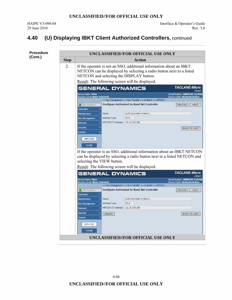
UNCLASSIFIED//FOR OFFICIAL USE ONLY HAIPE V3-098-04 Interface & Operator’s Guide 29 June 2010 Rev. 3.0
4-86
UNCLASSIFIED//FOR OFFICIAL USE ONLY
4.40 (U) Displaying IBKT Client Authorized Controllers, continued
Procedure (Cont.)
UNCLASSIFIED//FOR OFFICIAL USE ONLY Step Action
2. If the operator is not an SSO, additional information about an IBKT NETCON can be displayed by selecting a radio button next to a listed NETCON and selecting the DISPLAY button. Result: The following screen will be displayed.
If the operator is an SSO, additional information about an IBKT NETCON can be displayed by selecting a radio button next to a listed NETCON and selecting the VIEW button. Result: The following screen will be displayed.
UNCLASSIFIED//FOR OFFICIAL USE ONLY
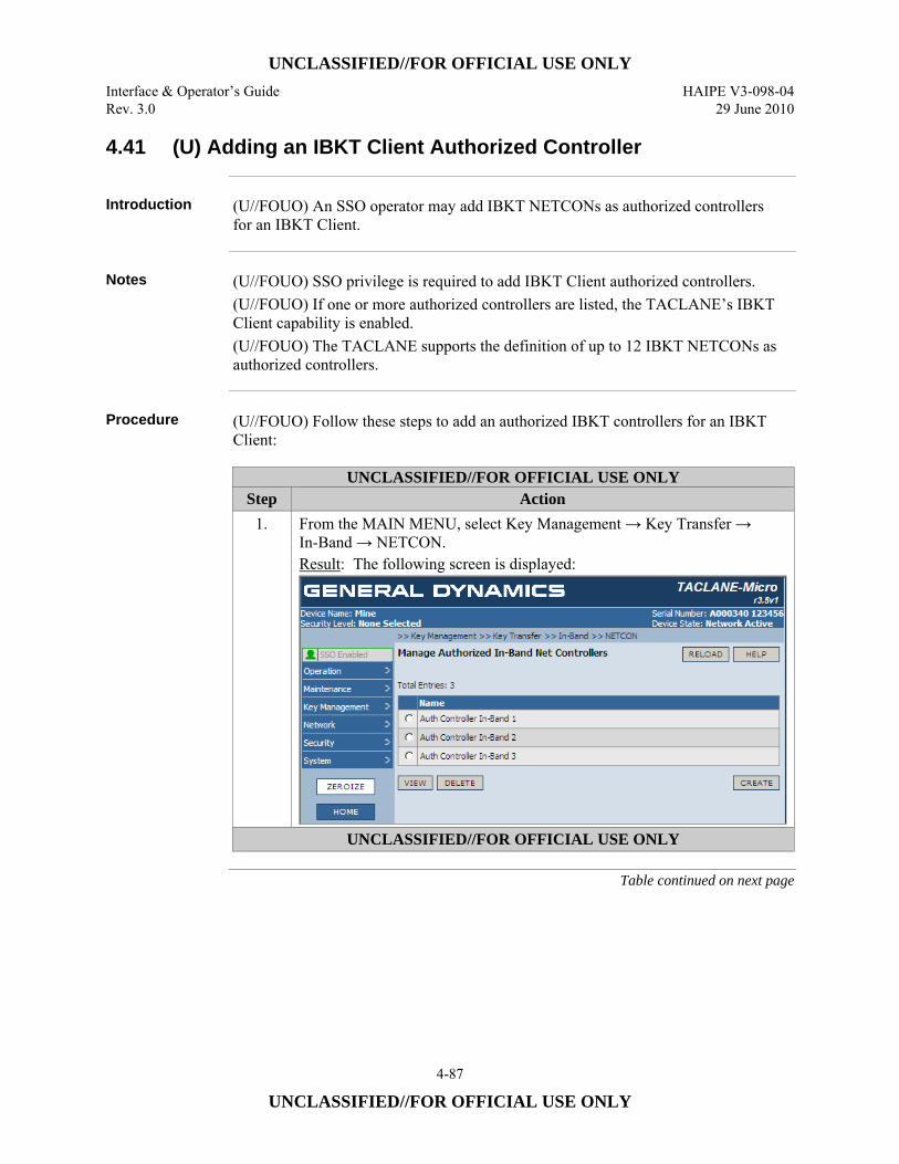
UNCLASSIFIED//FOR OFFICIAL USE ONLY Interface & Operator’s Guide HAIPE V3-098-04 Rev. 3.0 29 June 2010
4-87
UNCLASSIFIED//FOR OFFICIAL USE ONLY
4.41 (U) Adding an IBKT Client Authorized Controller
Introduction (U//FOUO) An SSO operator may add IBKT NETCONs as authorized controllers
for an IBKT Client.
Notes (U//FOUO) SSO privilege is required to add IBKT Client authorized controllers.
(U//FOUO) If one or more authorized controllers are listed, the TACLANE’s IBKT Client capability is enabled. (U//FOUO) The TACLANE supports the definition of up to 12 IBKT NETCONs as authorized controllers.
Procedure (U//FOUO) Follow these steps to add an authorized IBKT controllers for an IBKT
Client:
UNCLASSIFIED//FOR OFFICIAL USE ONLY Step Action
1. From the MAIN MENU, select Key Management → Key Transfer → In-Band → NETCON. Result: The following screen is displayed:
UNCLASSIFIED//FOR OFFICIAL USE ONLY
Table continued on next page
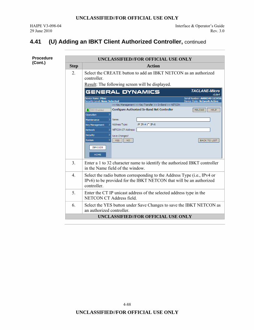
UNCLASSIFIED//FOR OFFICIAL USE ONLY HAIPE V3-098-04 Interface & Operator’s Guide 29 June 2010 Rev. 3.0
4-88
UNCLASSIFIED//FOR OFFICIAL USE ONLY
4.41 (U) Adding an IBKT Client Authorized Controller, continued
Procedure (Cont.)
UNCLASSIFIED//FOR OFFICIAL USE ONLY Step Action
2. Select the CREATE button to add an IBKT NETCON as an authorized controller. Result: The following screen will be displayed.
3. Enter a 1 to 32 character name to identify the authorized IBKT controller in the Name field of the window.
4. Select the radio button corresponding to the Address Type (i.e., IPv4 or IPv6) to be provided for the IBKT NETCON that will be an authorized controller.
5. Enter the CT IP unicast address of the selected address type in the NETCON CT Address field.
6. Select the YES button under Save Changes to save the IBKT NETCON as an authorized controller.
UNCLASSIFIED//FOR OFFICIAL USE ONLY
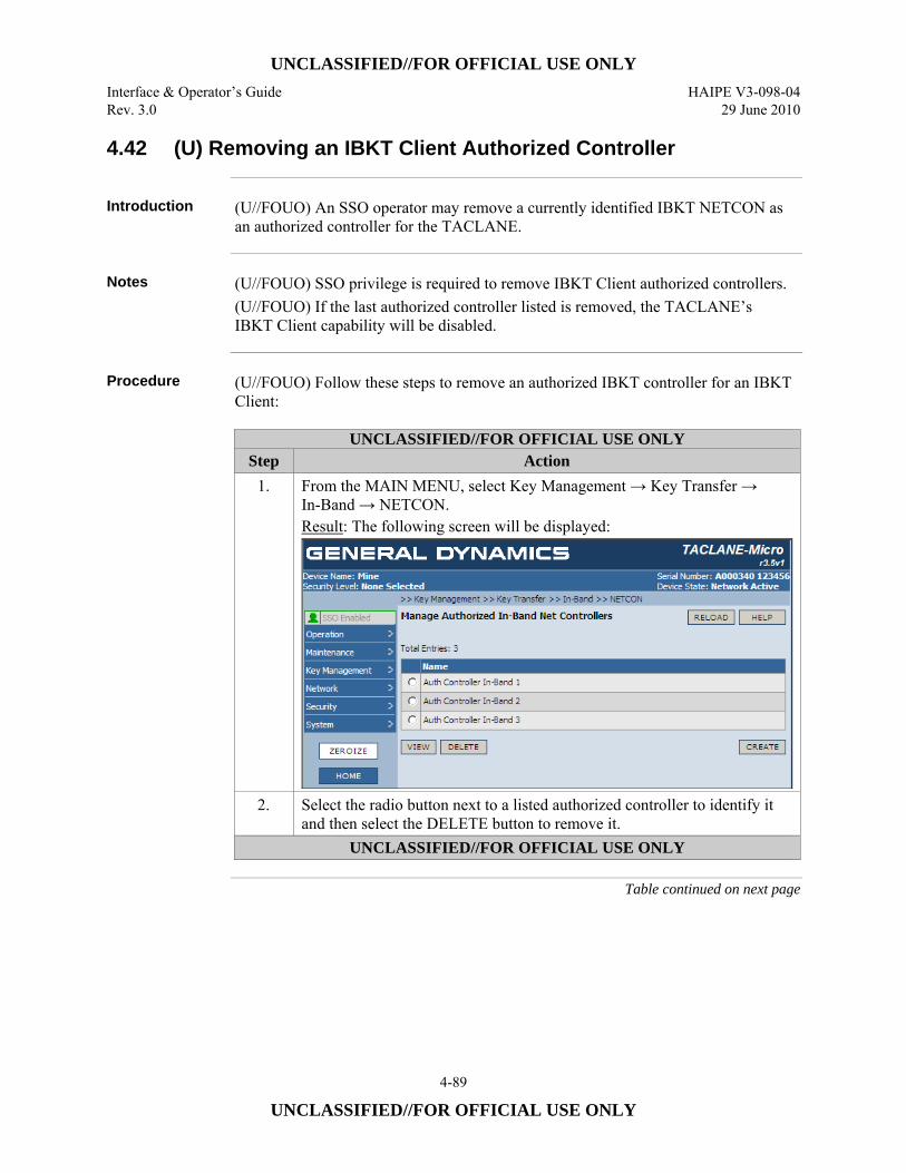
UNCLASSIFIED//FOR OFFICIAL USE ONLY Interface & Operator’s Guide HAIPE V3-098-04 Rev. 3.0 29 June 2010
4-89
UNCLASSIFIED//FOR OFFICIAL USE ONLY
4.42 (U) Removing an IBKT Client Authorized Controller
Introduction (U//FOUO) An SSO operator may remove a currently identified IBKT NETCON as
an authorized controller for the TACLANE.
Notes (U//FOUO) SSO privilege is required to remove IBKT Client authorized controllers.
(U//FOUO) If the last authorized controller listed is removed, the TACLANE’s IBKT Client capability will be disabled.
Procedure (U//FOUO) Follow these steps to remove an authorized IBKT controller for an IBKT
Client:
UNCLASSIFIED//FOR OFFICIAL USE ONLY Step Action
1. From the MAIN MENU, select Key Management → Key Transfer → In-Band → NETCON. Result: The following screen will be displayed:
2. Select the radio button next to a listed authorized controller to identify it and then select the DELETE button to remove it.
UNCLASSIFIED//FOR OFFICIAL USE ONLY
Table continued on next page
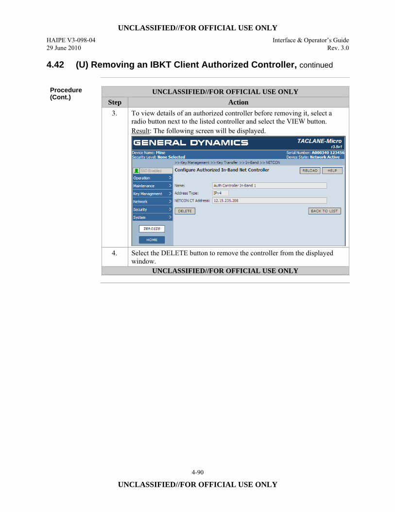
UNCLASSIFIED//FOR OFFICIAL USE ONLY HAIPE V3-098-04 Interface & Operator’s Guide 29 June 2010 Rev. 3.0
4-90
UNCLASSIFIED//FOR OFFICIAL USE ONLY
4.42 (U) Removing an IBKT Client Authorized Controller, continued
Procedure (Cont.)
UNCLASSIFIED//FOR OFFICIAL USE ONLY Step Action
3. To view details of an authorized controller before removing it, select a radio button next to the listed controller and select the VIEW button. Result: The following screen will be displayed.
4. Select the DELETE button to remove the controller from the displayed window.
UNCLASSIFIED//FOR OFFICIAL USE ONLY
UNCLASSIFIED//FOR OFFICIAL USE ONLY Interface & Operator’s Guide HAIPE V3-098-04 Rev. 3.0 29 June 2010
4-91
UNCLASSIFIED//FOR OFFICIAL USE ONLY
4.43 (U) Displaying IBKT Client PPKs Disabled for Supersession
Introduction (U//FOUO) An operator may display a list of traffic PPKs that have been disabled
for IBKT supersession at an IBKT Client.
Notes (U//FOUO) By default, traffic PPKs are enabled for IBKT supersession.
(U//FOUO) The TACLANE allows up to 72 traffic PPKs to be disabled for supersession.
Procedure (U//FOUO) Follow these steps to display the PPKs that have been disabled for
supersession at an IBKT Client.
Continued on next page
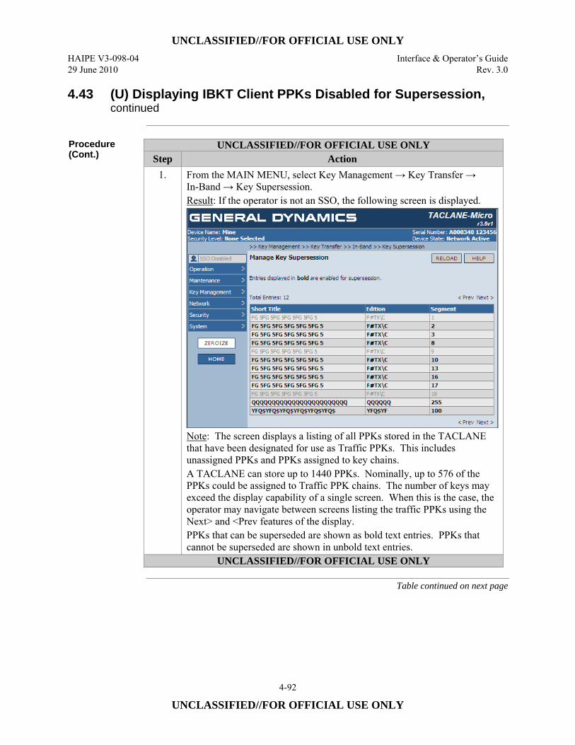
UNCLASSIFIED//FOR OFFICIAL USE ONLY HAIPE V3-098-04 Interface & Operator’s Guide 29 June 2010 Rev. 3.0
4-92
UNCLASSIFIED//FOR OFFICIAL USE ONLY
4.43 (U) Displaying IBKT Client PPKs Disabled for Supersession, continued
Procedure (Cont.)
UNCLASSIFIED//FOR OFFICIAL USE ONLY Step Action
1. From the MAIN MENU, select Key Management → Key Transfer → In-Band → Key Supersession. Result: If the operator is not an SSO, the following screen is displayed.
Note: The screen displays a listing of all PPKs stored in the TACLANE that have been designated for use as Traffic PPKs. This includes unassigned PPKs and PPKs assigned to key chains. A TACLANE can store up to 1440 PPKs. Nominally, up to 576 of the PPKs could be assigned to Traffic PPK chains. The number of keys may exceed the display capability of a single screen. When this is the case, the operator may navigate between screens listing the traffic PPKs using the Next> and <Prev features of the display. PPKs that can be superseded are shown as bold text entries. PPKs that cannot be superseded are shown in unbold text entries.
UNCLASSIFIED//FOR OFFICIAL USE ONLY
Table continued on next page
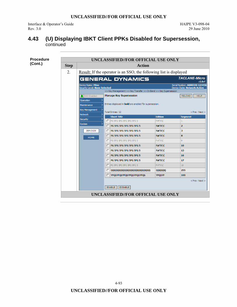
UNCLASSIFIED//FOR OFFICIAL USE ONLY Interface & Operator’s Guide HAIPE V3-098-04 Rev. 3.0 29 June 2010
4-93
UNCLASSIFIED//FOR OFFICIAL USE ONLY
4.43 (U) Displaying IBKT Client PPKs Disabled for Supersession, continued
Procedure (Cont.)
UNCLASSIFIED//FOR OFFICIAL USE ONLY Step Action
2. Result: If the operator is an SSO, the following list is displayed
UNCLASSIFIED//FOR OFFICIAL USE ONLY
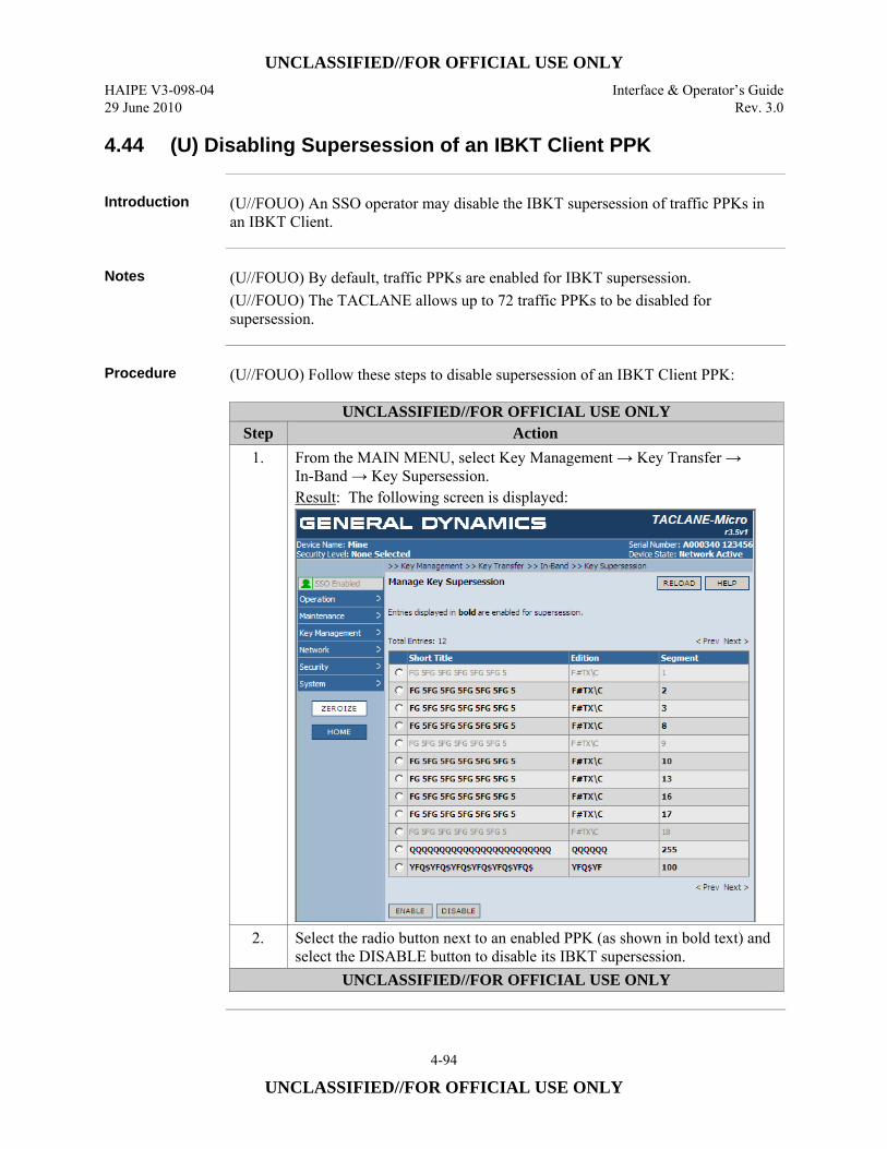
UNCLASSIFIED//FOR OFFICIAL USE ONLY HAIPE V3-098-04 Interface & Operator’s Guide 29 June 2010 Rev. 3.0
4-94
UNCLASSIFIED//FOR OFFICIAL USE ONLY
4.44 (U) Disabling Supersession of an IBKT Client PPK
Introduction (U//FOUO) An SSO operator may disable the IBKT supersession of traffic PPKs in
an IBKT Client.
Notes (U//FOUO) By default, traffic PPKs are enabled for IBKT supersession.
(U//FOUO) The TACLANE allows up to 72 traffic PPKs to be disabled for supersession.
Procedure (U//FOUO) Follow these steps to disable supersession of an IBKT Client PPK:
UNCLASSIFIED//FOR OFFICIAL USE ONLY Step Action
1. From the MAIN MENU, select Key Management → Key Transfer → In-Band → Key Supersession. Result: The following screen is displayed:
2. Select the radio button next to an enabled PPK (as shown in bold text) and select the DISABLE button to disable its IBKT supersession.
UNCLASSIFIED//FOR OFFICIAL USE ONLY

UNCLASSIFIED//FOR OFFICIAL USE ONLY Interface & Operator’s Guide HAIPE V3-098-04 Rev. 3.0 29 June 2010
4-95
UNCLASSIFIED//FOR OFFICIAL USE ONLY
4.45 (U) Reenabling Supersession of an IBKT Client PPK
Introduction (U//FOUO) An SSO operator may reenable supersession of PPK that is currently
disabled for IBKT supersession.
Notes (U//FOUO) By default, traffic PPKs are enabled for IBKT supersession.
(U//FOUO) The TACLANE allows up to 72 traffic PPKs to be disabled for supersession.
Procedure (U//FOUO) Follow these steps to reenable supersession of an IBKT Client PPK:
UNCLASSIFIED//FOR OFFICIAL USE ONLY Step Action
1. From the MAIN MENU, select Key Management → Key Transfer → In-Band → Key Supersession. Result: The following screen is displayed:
2. Select the radio button next to a PPK that is disabled (i.e., an entry that is not bold) and select the ENABLE button to enable its IBKT supersession.
UNCLASSIFIED//FOR OFFICIAL USE ONLY

UNCLASSIFIED//FOR OFFICIAL USE ONLY HAIPE V3-098-04 Interface & Operator’s Guide 29 June 2010 Rev. 3.0
4-96
UNCLASSIFIED//FOR OFFICIAL USE ONLY
(U) This page intentionally left blank.
UNCLASSIFIED//FOR OFFICIAL USE ONLY Interface & Operator’s Guide HAIPE V3-098-04 Rev. 3.0 29 June 2010
5-1
UNCLASSIFIED//FOR OFFICIAL USE ONLY
5.0 (U) CONFIGURING IP/ETHERNET
5.1 (U) Configuring the Ethernet Media and Physical Parameters
Introduction (U//FOUO) The TACLANE PT and CT Ethernet interface speed, duplex mode, and
media are selectable by the operator. These are selected to match the network devices to which a TACLANE is connected. In addition, each Ethernet interface can be enabled or disabled. (U//FOUO) The TACLANE supports both auto-negotiation and manual configuration when connecting using copper media. The TACLANE automatically negotiates an identical speed and mode with all interfacing network devices when set to the auto-negotiation option. The TACLANE establishes a connection at the highest data rate that is consistent with operator-defined speed/mode options and compatible with the interfacing devices.
Supported TACLANE Physical Settings
(U//FOUO) The TACLANE supports the following user-configurable Ethernet physical settings. Copper interfaces: • Auto-Negotiate • 1000 Mbps/Full Duplex (TACLANE-GigE only) • 100 Mbps/Full Duplex • 100 Mbps/Half Duplex • 10 Mbps/Full Duplex • 10 Mbps/Half Duplex
Fiber interfaces: • 100 Mbps/Full Duplex (TACLANE-Micro only) • 1000 Mbps/Full Duplex (TACLANE-GigE only)
(U//FOUO) The default medium for both the PT and CT interfaces is copper. (U//FOUO) The default setting for a TACLANE copper interface is Auto-Negotiate with all speed/mode combinations advertised. (U//FOUO) The TACLANE-Micro always utilizes a 100 Mbps/ Full Duplex configuration on fiber interfaces. The TACLANE-GigE always uses 1000 Mbps/Full Duplex on its fiber interfaces.
Continued on next page
UNCLASSIFIED//FOR OFFICIAL USE ONLY HAIPE V3-098-04 Interface & Operator’s Guide 29 June 2010 Rev. 3.0
5-2
UNCLASSIFIED//FOR OFFICIAL USE ONLY
5.1 (U) Configuring the Ethernet Media and Physical Parameters, continued
Auto-Negotiate Notes
(U//FOUO) The following notes apply when the Ethernet physical parameter is set to Auto-Negotiate: • (U//FOUO) If the physical parameter is set to Auto-Negotiate, a two-stage
negotiation process is carried out. First, each interface auto-negotiates with its link partner, offering all the advertised bandwidths. Then, the TACLANE selects the highest bandwidth that is within the capabilities of both link partners, and auto-negotiates with both devices again, offering only the selected bandwidth.
• (U//FOUO) Auto-negotiation should take between 2 – 6 seconds, depending on the network speed capabilities
• (U//FOUO) If the auto-negotiation fails because the link partner is only advertising speed/mode combinations that are not compatible with the TACLANE configuration, the TACLANE will continue to try auto-negotiation until a response is received.
• (U//FOUO) The TACLANE’s network interface will automatically re-negotiate (assuming it was configured to auto-negotiate) when it detects network changes (e.g., link, speed, duplex, clocking).
• (U//FOUO) If the negotiation fails because a link partner is set to a constant bandwidth or does not support auto-negotiation, then the speed is sensed using Parallel Detection. Since Parallel Detection does not determine full or half duplex, the interface will automatically use half duplex. (This is the correct behavior according to the standard, although it sometimes produces unsatisfactory results, since Parallel Detection cannot sense the remote device’s duplex setting.) Parallel detection is only used for 10/100BASE-T equipment.
Other Notes (U//FOUO) The following additional notes apply to configuring the Ethernet
physical parameters: • (U//FOUO) The PT and CT physical interface settings are independent. For
example, it’s possible to have a TACLANE configured with its CT interface at 100/F and its PT interface set to Auto-Negotiate.
• (U//FOUO) A manual interface speed setting should be used if the TACLANE interfaces with network equipment that doesn’t support auto-negotiation.
• (U//FOUO) If the Ethernet Configuration is changed from Fiber to Copper or vice-versa in the Network Active or Secure Comms state, then there will be a period, up to about 5 seconds, where all packets will be dropped.
Continued on next page
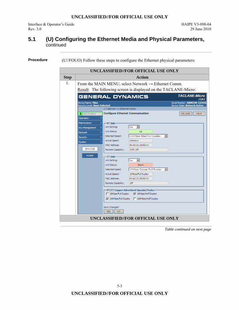
UNCLASSIFIED//FOR OFFICIAL USE ONLY Interface & Operator’s Guide HAIPE V3-098-04 Rev. 3.0 29 June 2010
5-3
UNCLASSIFIED//FOR OFFICIAL USE ONLY
5.1 (U) Configuring the Ethernet Media and Physical Parameters, continued
Procedure (U//FOUO) Follow these steps to configure the Ethernet physical parameters:
UNCLASSIFIED//FOR OFFICIAL USE ONLY Step Action
1. From the MAIN MENU, select Network → Ethernet Comm. Result: The following screen is displayed on the TACLANE-Micro:
UNCLASSIFIED//FOR OFFICIAL USE ONLY
Table continued on next page
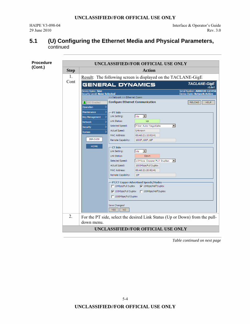
UNCLASSIFIED//FOR OFFICIAL USE ONLY HAIPE V3-098-04 Interface & Operator’s Guide 29 June 2010 Rev. 3.0
5-4
UNCLASSIFIED//FOR OFFICIAL USE ONLY
5.1 (U) Configuring the Ethernet Media and Physical Parameters, continued
Procedure (Cont.)
UNCLASSIFIED//FOR OFFICIAL USE ONLY Step Action
1. Cont
Result: The following screen is displayed on the TACLANE-GigE
2. For the PT side, select the desired Link Status (Up or Down) from the pull-down menu.
UNCLASSIFIED//FOR OFFICIAL USE ONLY
Table continued on next page
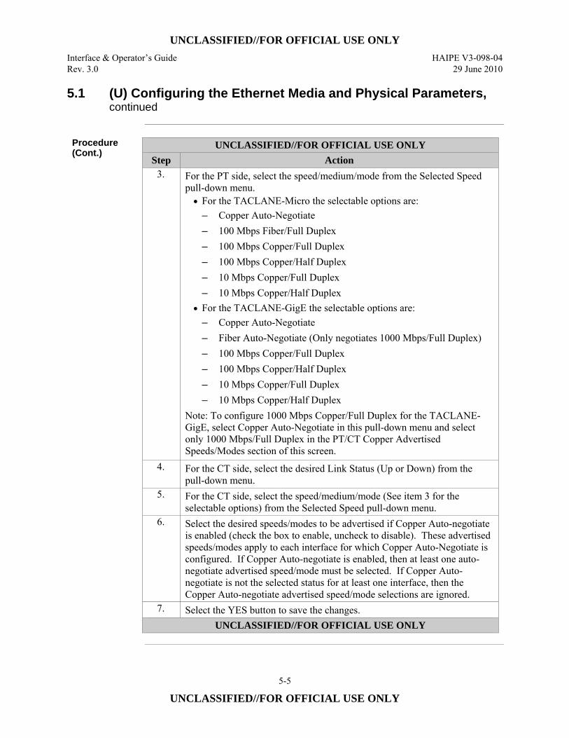
UNCLASSIFIED//FOR OFFICIAL USE ONLY Interface & Operator’s Guide HAIPE V3-098-04 Rev. 3.0 29 June 2010
5-5
UNCLASSIFIED//FOR OFFICIAL USE ONLY
5.1 (U) Configuring the Ethernet Media and Physical Parameters, continued
Procedure (Cont.)
UNCLASSIFIED//FOR OFFICIAL USE ONLY Step Action
3. For the PT side, select the speed/medium/mode from the Selected Speed pull-down menu. • For the TACLANE-Micro the selectable options are:
– Copper Auto-Negotiate – 100 Mbps Fiber/Full Duplex – 100 Mbps Copper/Full Duplex – 100 Mbps Copper/Half Duplex – 10 Mbps Copper/Full Duplex – 10 Mbps Copper/Half Duplex
• For the TACLANE-GigE the selectable options are: – Copper Auto-Negotiate – Fiber Auto-Negotiate (Only negotiates 1000 Mbps/Full Duplex) – 100 Mbps Copper/Full Duplex – 100 Mbps Copper/Half Duplex – 10 Mbps Copper/Full Duplex – 10 Mbps Copper/Half Duplex
Note: To configure 1000 Mbps Copper/Full Duplex for the TACLANE-GigE, select Copper Auto-Negotiate in this pull-down menu and select only 1000 Mbps/Full Duplex in the PT/CT Copper Advertised Speeds/Modes section of this screen.
4. For the CT side, select the desired Link Status (Up or Down) from the pull-down menu.
5. For the CT side, select the speed/medium/mode (See item 3 for the selectable options) from the Selected Speed pull-down menu.
6. Select the desired speeds/modes to be advertised if Copper Auto-negotiate is enabled (check the box to enable, uncheck to disable). These advertised speeds/modes apply to each interface for which Copper Auto-Negotiate is configured. If Copper Auto-negotiate is enabled, then at least one auto-negotiate advertised speed/mode must be selected. If Copper Auto-negotiate is not the selected status for at least one interface, then the Copper Auto-negotiate advertised speed/mode selections are ignored.
7. Select the YES button to save the changes. UNCLASSIFIED//FOR OFFICIAL USE ONLY
UNCLASSIFIED//FOR OFFICIAL USE ONLY HAIPE V3-098-04 Interface & Operator’s Guide 29 June 2010 Rev. 3.0
5-6
UNCLASSIFIED//FOR OFFICIAL USE ONLY
5.2 (U) Entering/Modifying the TACLANE IPv4 Network Configuration
Introduction (U//FOUO) The Operator configures the TACLANE IPv4 interfaces as described in
this section. The TACLANE supports manual configuration of: • IPv4 addresses • IPv4 default gateway addresses • Maximum Transfer Unit (MTU) • Link status • HMI Interface Address (TACLANE-Micro only) • IM-PEPD Segmented Core Mode (CT only) • NAT-T processing (CT only)
Notes (U//FOUO) The following notes apply to entering/modifying the TACLANE IP
addresses: • (U//FOUO) The CT and PT IP addresses must include the prefix length in the
format /XX as a suffix to the IPv4 address. [XX is the number of bits of the IPv4 address that are used by the prefix (subnet mask)].
• (U//FOUO) Any change to the IP network configuration will take effect immediately following the acceptance of the change (upon selecting the YES button).
• (U//FOUO) Modifying or deleting an interface address will delete all configuration information referencing it, including Security Associations. Deleted Security Associations will have to be re-established.
• (U//FOUO) The Gateway address must be consistent with the corresponding interface Address (e.g., PT Gateway must be consistent with the PT Address)
• (U//FOUO) The TACLANE can be configured with its CT and PT IP addresses in the same or in different subnets.
• (U//FOUO) The CT and PT IP addresses must be unique such that no host or remote device (e.g., another TACLANE) uses these IP addresses.
• (U//FOUO) The HMI Interface only supports IPv4 addresses.
Continued on next page
UNCLASSIFIED//FOR OFFICIAL USE ONLY Interface & Operator’s Guide HAIPE V3-098-04 Rev. 3.0 29 June 2010
5-7
UNCLASSIFIED//FOR OFFICIAL USE ONLY
5.2 (U) Entering/Modifying the TACLANE IPv4 Network Configuration, continued
Maximum Transfer Unit (MTU) and Fixed Packet Length (FPL)
(U//FOUO) The following notes apply to modifying the MTU size: • (U//FOUO) The operator may modify the TACLANE Maximum Transfer Unit
(MTU) size. The MTU size is the length, in bytes, of the largest IP datagram the TACLANE sends without fragmenting the IP datagram.
• (U//FOUO) TACLANE defaults the MTU size to 1500 bytes. The minimum possible MTU size for IPv4 is 576 bytes. For the TACLANE-Micro, the maximum MTU size is 1500 bytes. For the TACLANE-GigE, the maximum MTU size is 2176 bytes.
• (U//FOUO) TACLANE disregards the Don’t Fragment (DF) bit in the IP header because ESP increases the packet size, which can create packets that require fragmentation to comply with MTU. For optimum performance when Fixed Packet Length (FPL) is enabled, PT-side hosts and routers may require modifications to their MTU settings. See Section B.3 of Appendix B for more information.
Segmented Core Mode
(U//FOUO) The following notes apply to enabling and disabling Segmented Core. • (U//FOUO) Segmented Core mode of IM-PEPD works in a fashion similar to
basic IM-PEPD with the exception that ECUs which are configured with Segmented Core enabled, will listen to all IKE 1 messages which come in on the CT interface of the device. The ECU will respond to IKE 1 messages that are addressed to any address in the ECU’s COI. This mode of IM-PEPD is intended to accommodate ECUs which front a large number of PT prefixes which are not easily aggregable to a single prefix. Segmented Core mode allows for the discovery of PT networks with prefixes that are different than the prefix of the fronting ECU.
• (U//FOUO) Segmented Core Setting only applies to the CT interface • (U//FOUO) Segmented Core is disabled on the TACLANE by default
Continued on next page
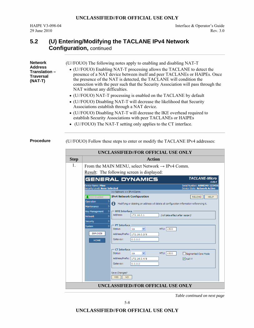
UNCLASSIFIED//FOR OFFICIAL USE ONLY HAIPE V3-098-04 Interface & Operator’s Guide 29 June 2010 Rev. 3.0
5-8
UNCLASSIFIED//FOR OFFICIAL USE ONLY
5.2 (U) Entering/Modifying the TACLANE IPv4 Network Configuration, continued
Network Address Translation –Traversal (NAT-T)
(U//FOUO) The following notes apply to enabling and disabling NAT-T • (U//FOUO) Enabling NAT-T processing allows the TACLANE to detect the
presence of a NAT device between itself and peer TACLANEs or HAIPEs. Once the presence of the NAT is detected, the TACLANE will condition the connection with the peer such that the Security Association will pass through the NAT without any difficulties.
• (U//FOUO) NAT-T processing is enabled on the TACLANE by default • (U//FOUO) Disabling NAT-T will decrease the likelihood that Security
Associations establish through a NAT device. • (U//FOUO) Disabling NAT-T will decrease the IKE overhead required to
establish Security Associations with peer TACLANEs or HAIPEs • (U//FOUO) The NAT-T setting only applies to the CT interface.
Procedure (U//FOUO) Follow these steps to enter or modify the TACLANE IPv4 addresses:
UNCLASSIFIED//FOR OFFICIAL USE ONLY Step Action
1. From the MAIN MENU, select Network → IPv4 Comm. Result: The following screen is displayed:
UNCLASSIFIED//FOR OFFICIAL USE ONLY
Table continued on next page
UNCLASSIFIED//FOR OFFICIAL USE ONLY Interface & Operator’s Guide HAIPE V3-098-04 Rev. 3.0 29 June 2010
5-9
UNCLASSIFIED//FOR OFFICIAL USE ONLY
5.2 (U) Entering/Modifying the TACLANE IPv4 Network Configuration, continued
Procedure (Cont.)
UNCLASSIFIED//FOR OFFICIAL USE ONLY Step Action
2. For the PT Interface, enter the Interface Status (Up, Down). 3. For the PT Interface, enter the MTU value.
• For the Micro, the default is 1500 and the range is 576 to 1500. • For the GigE, the default is 1500, and the range is 576 to 2176.
4. For the PT Interface, enter the PT IPv4 Address and Prefix length separated by a “/”. Format is XXX.XXX.XXX.XXX/XX. Prefix length is the number of high-order bits of the IPv4 address used for the prefix (bit-length of subnet mask).
5. For the PT Interface, enter the IPv4 Gateway Address (no prefix). 6. For the CT Interface, enter the Interface Status (Up, Down). 7. For the CT Interface, enter the MTU value.
• For the Micro, the default is 1500 and the range is 576 to 1500. • For the GigE, the default is 1500 and the range is 576 to 2176.
8. For the CT Interface, enter the CT IPv4 Address and Prefix separated by a “/”. Format is XXX.XXX.XXX.XXX/XX Prefix length is the number of high-order bits of the IPv4 address used for the prefix (bit-length of subnet mask).
9. For the CT Interface, enter the IPv4 Gateway Address (no prefix). Format is XXX.XXX.XXX.XXX.
10. For the CT Interface, enable or disable Segmented Core Mode (check the box to enable, uncheck to disable)
11. For the CT Interface, enable or disable NAT-T (check the box to enable, uncheck to disable)
12. Select the YES button to save changes. UNCLASSIFIED//FOR OFFICIAL USE ONLY
UNCLASSIFIED//FOR OFFICIAL USE ONLY HAIPE V3-098-04 Interface & Operator’s Guide 29 June 2010 Rev. 3.0
5-10
UNCLASSIFIED//FOR OFFICIAL USE ONLY
5.3 (U) Entering/Modifying the TACLANE IPv6 PT Interface Configuration
Introduction (U//FOUO) Through two levels of screens, the Operator configures the TACLANE
IPv6 Plain Text (PT) interface as described in this section. (U//FOUO) The TACLANE supports manual configuration of the following parameters for the PT interface: • IPv6 PT Interface Options:
– Up/Down Status – MTU – Duplicate Address Detection (DAD) Recovery ID – Duplicate Address Detection Enable
• IPv6 Interface ID • Gateway Address
Notes (U//FOUO) The following notes apply to entering/modifying the TACLANE IP
addresses: • (U//FOUO) Any change to the IP network configuration will take effect
immediately following the acceptance of the change (upon selecting the YES button).
• (U//FOUO) Modifying or deleting an interface address will delete all configuration information referencing it, including Security Associations.
• (U//FOUO) The Gateway address must be consistent with the corresponding interface address.
• (U//FOUO) The DAD Recovery ID and the PT Interface Identifier must not be equal. If it is attempted to set them equal, the change will be rejected by the TACLANE.
• (U//FOUO) The IPv6 Interface ID can be manually configured. • (U//FOUO) If the IPv6 Interface ID s used to automatically form either of the PT
Addresses, then a change to the IPv6 Interface ID will cause the automatically formed PT Address to also change.
• (U//FOUO) If Duplicate Address Detection is enabled, then any manually configured address or Interface ID must pass Duplicate Address Detection before it can be assigned to the interface.
Continued on next page
UNCLASSIFIED//FOR OFFICIAL USE ONLY Interface & Operator’s Guide HAIPE V3-098-04 Rev. 3.0 29 June 2010
5-11
UNCLASSIFIED//FOR OFFICIAL USE ONLY
5.3 (U) Entering/Modifying the TACLANE IPv6 PT Interface Configuration, continued
MTU and FPL (U//FOUO) The following notes apply to modifying the MTU size:
• (U//FOUO) The operator may modify the TACLANE Maximum Transfer Unit (MTU) size. The MTU size is the length, in bytes, of the largest IPv6 datagram the TACLANE sends from the associated interface without fragmenting the IP datagram.
• (U//FOUO) TACLANE defaults the MTU size to 1500 bytes. The minimum possible MTU size for IPv6 is 1280 bytes. For the TACLANE-Micro, the maximum MTU size is 1500 bytes. For the TACLANE-GigE, the maximum MTU size is 2176 bytes.
• (U//FOUO) For optimum performance when FPL is enabled, PT-side hosts and routers may require modifications to their MTU settings. See Section B.3 of Appendix B for more information.
Continued on next page
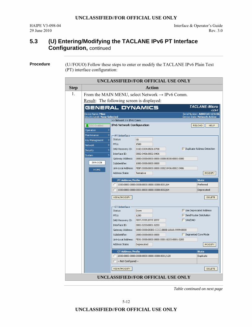
UNCLASSIFIED//FOR OFFICIAL USE ONLY HAIPE V3-098-04 Interface & Operator’s Guide 29 June 2010 Rev. 3.0
5-12
UNCLASSIFIED//FOR OFFICIAL USE ONLY
5.3 (U) Entering/Modifying the TACLANE IPv6 PT Interface Configuration, continued
Procedure (U//FOUO) Follow these steps to enter or modify the TACLANE IPv6 Plain Text
(PT) interface configuration:
UNCLASSIFIED//FOR OFFICIAL USE ONLY Step Action
1. From the MAIN MENU, select Network → IPv6 Comm. Result: The following screen is displayed:
UNCLASSIFIED//FOR OFFICIAL USE ONLY
Table continued on next page

UNCLASSIFIED//FOR OFFICIAL USE ONLY Interface & Operator’s Guide HAIPE V3-098-04 Rev. 3.0 29 June 2010
5-13
UNCLASSIFIED//FOR OFFICIAL USE ONLY
5.3 (U) Entering/Modifying the TACLANE IPv6 PT Interface Configuration, continued
Procedure (Cont.)
UNCLASSIFIED//FOR OFFICIAL USE ONLY Step Action
2. To enter or modify the PT Interface IP configuration, select the MODIFY button in the PT Interface outlined area of the screen. Result: The following screen is displayed:
3. Select the Interface Status (Up, Down) from the pull-down menu. 4. Enter the MTU value.
• For Micro, the default is 1500 and the range is 1280 to 1500. • For GigE, the default is 1500 and the range is 1280 to 2176.
5. Enter the DAD Recovery ID. Format is XXXX.XXXX.XXXX.XXXX. 6. Enable or Disable Duplicate Address Detection (check the box to enable,
uncheck to disable). 7. Enter the IPv6 Interface ID. Format is XXXX.XXXX.XXXX.XXXX. 8. Enter the Gateway Address. Format is a full IPv6 unicast address with no
prefix. 9. Select the YES button to save changes.
UNCLASSIFIED//FOR OFFICIAL USE ONLY
UNCLASSIFIED//FOR OFFICIAL USE ONLY HAIPE V3-098-04 Interface & Operator’s Guide 29 June 2010 Rev. 3.0
5-14
UNCLASSIFIED//FOR OFFICIAL USE ONLY
5.4 (U) Entering/Modifying the TACLANE IPv6 PT Network Addresses
Introduction (U//FOUO) Through two levels of screens, the Operator configures the TACLANE
IPv6 Plain Text (PT) interface addresses as described in this section. (U//FOUO) The TACLANE supports manual configuration of the following parameters for the IPv6 addresses on the PT interface: • PT Interface IPv6 Addresses 1 and 2
– Address/Prefix – Preferred Lifetime – Valid Lifetime – Enable
On-Link Flag Autonomous Flag Advertise Prefix
Notes (U//FOUO) The following notes apply to entering/modifying the TACLANE IP
addresses: • (U//FOUO) The PT IPv6 addresses must include the prefix length following the
address in the format /XXX. • (U//FOUO) Any change to the IP network configuration will take effect
immediately following the acceptance of the change (upon selecting the YES button).
• (U//FOUO) Modifying or deleting an interface address will delete all configuration information referencing it, including Security Associations.
• (U//FOUO) The PT Addresses can be configured in the same or in different subnets as the CT Addresses.
• (U//FOUO) The PT IPv6 addresses must be unique such that no host or remote device (e.g., another TACLANE) uses these IP addresses.
• (U//FOUO) The Interface ID can be used to automatically form one of the IPv6 PT Addresses (USE INTF ID button in Address Information box, then add first 4 hexadecimal components of the address). If that is done, then a change to the Interface ID will cause the automatically formed Address to also change.
• (U//FOUO) If Duplicate Address Detection is enabled, then any manually configured address or Interface ID must pass Duplicate Address Detection before it can be assigned to the interface.
Continued on next page

UNCLASSIFIED//FOR OFFICIAL USE ONLY Interface & Operator’s Guide HAIPE V3-098-04 Rev. 3.0 29 June 2010
5-15
UNCLASSIFIED//FOR OFFICIAL USE ONLY
5.4 (U) Entering/Modifying the TACLANE IPv6 PT Network Addresses, continued
Procedure (U//FOUO) Follow these steps to enter or modify the TACLANE IPv6 Plain Text
(PT) IPv6 interface addresses:
UNCLASSIFIED//FOR OFFICIAL USE ONLY Step Action
1. From the MAIN MENU, select Network → IPv6 Comm. Result: The following screen is displayed:
UNCLASSIFIED//FOR OFFICIAL USE ONLY
Table continued on next page
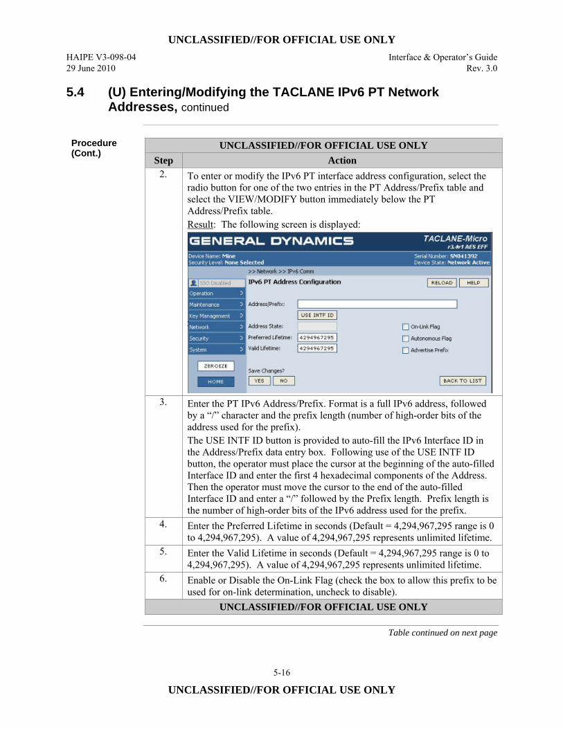
UNCLASSIFIED//FOR OFFICIAL USE ONLY HAIPE V3-098-04 Interface & Operator’s Guide 29 June 2010 Rev. 3.0
5-16
UNCLASSIFIED//FOR OFFICIAL USE ONLY
5.4 (U) Entering/Modifying the TACLANE IPv6 PT Network Addresses, continued
Procedure (Cont.)
UNCLASSIFIED//FOR OFFICIAL USE ONLY Step Action
2. To enter or modify the IPv6 PT interface address configuration, select the radio button for one of the two entries in the PT Address/Prefix table and select the VIEW/MODIFY button immediately below the PT Address/Prefix table. Result: The following screen is displayed:
3. Enter the PT IPv6 Address/Prefix. Format is a full IPv6 address, followed by a “/” character and the prefix length (number of high-order bits of the address used for the prefix). The USE INTF ID button is provided to auto-fill the IPv6 Interface ID in the Address/Prefix data entry box. Following use of the USE INTF ID button, the operator must place the cursor at the beginning of the auto-filled Interface ID and enter the first 4 hexadecimal components of the Address. Then the operator must move the cursor to the end of the auto-filled Interface ID and enter a “/” followed by the Prefix length. Prefix length is the number of high-order bits of the IPv6 address used for the prefix.
4. Enter the Preferred Lifetime in seconds (Default = 4,294,967,295 range is 0 to 4,294,967,295). A value of 4,294,967,295 represents unlimited lifetime.
5. Enter the Valid Lifetime in seconds (Default = 4,294,967,295 range is 0 to 4,294,967,295). A value of 4,294,967,295 represents unlimited lifetime.
6. Enable or Disable the On-Link Flag (check the box to allow this prefix to be used for on-link determination, uncheck to disable).
UNCLASSIFIED//FOR OFFICIAL USE ONLY
Table continued on next page
UNCLASSIFIED//FOR OFFICIAL USE ONLY Interface & Operator’s Guide HAIPE V3-098-04 Rev. 3.0 29 June 2010
5-17
UNCLASSIFIED//FOR OFFICIAL USE ONLY
5.4 (U) Entering/Modifying the TACLANE IPv6 PT Network Addresses, continued
Procedure (Cont.)
UNCLASSIFIED//FOR OFFICIAL USE ONLY Step Action
7. Enable or Disable the Autonomous Flag (check the box to allow this prefix to be used for autonomous address configuration (i.e., can be used to form a local interface address using stateless auto-configuration), uncheck to disable).
8. Enable or Disable Advertise Prefix (check the box to have the address prefix included in router advertisements, uncheck to disable).
9. Select the YES button to save changes. UNCLASSIFIED//FOR OFFICIAL USE ONLY
5.5 (U) Entering/Modifying a TACLANE IPv6 CT Interface
Configuration
Introduction (U//FOUO) Through two levels of screens, the Operator configures the TACLANE
IPv6 Cipher Text (CT) interfaces as described in this section. (U//FOUO) The TACLANE supports manual configuration of the following IPv6 CT Interface Options: • IPv6 CT Interface parameters:
– Up/Down Status – Enable use of Deprecated Address – Enable the sending of Router Solicitations – Enable Stateless Address Autoconfiguration (SAA)/Duplicate Address
Detection (DAD) – Enable Segmented Core Mode – Enable NAT-T (only available on GigE)
• CT Interface MTU • DAD Recovery ID • Link Local Interface ID • Gateway Address
Continued on next page
UNCLASSIFIED//FOR OFFICIAL USE ONLY HAIPE V3-098-04 Interface & Operator’s Guide 29 June 2010 Rev. 3.0
5-18
UNCLASSIFIED//FOR OFFICIAL USE ONLY
5.5 (U) Entering/Modifying a TACLANE IPv6 CT Interface Configuration, continued
Notes (U//FOUO) The following notes apply to entering/modifying the TACLANE IP
addresses: • (U//FOUO) Any change to the IP network configuration will take effect
immediately following the acceptance of the change (upon selecting the YES button).
• (U//FOUO) The Gateway address must be consistent with the corresponding interface address.
• (U//FOUO) The PT Addresses can be configured in the same or in different subnets as the CT Addresses.
• (U//FOUO) The CT IPv6 addresses must be unique such that no host or remote device (e.g., another TACLANE) uses these IP addresses.
• (U//FOUO) The DAD Recovery ID and the CT Interface Identifier must not be equal. If it is attempted to set them equal, the change will be rejected by the TACLANE.
• (U//FOUO) The Interface ID can be manually configured. • (U//FOUO) The Interface ID can be used to automatically form one of the CT
Addresses (USE INTF ID button in Address Information box). If that is done, then a change to the Interface ID will cause the automatically formed Address to also change.
• (U//FOUO) If Duplicate Address Detection is enabled, then any manually configured address or Interface ID must pass Duplicate Address Detection before it can be assigned to the interface.
(U//FOUO) The following notes apply to modifying the MTU size: • (U//FOUO) The operator may modify the TACLANE Maximum Transfer Unit
(MTU) size. The MTU size is the length, in bytes, of the largest IPv6 datagram the TACLANE sends from the associated interface without fragmenting the IP datagram.
• (U//FOUO) TACLANE defaults the MTU size to 1500 bytes. The minimum possible MTU size for IPv6 is 1280 bytes. For the TACLANE-Micro, the maximum MTU size is 1500 bytes. For the TACLANE-GigE, the maximum MTU size is 2176.
Continued on next page
UNCLASSIFIED//FOR OFFICIAL USE ONLY Interface & Operator’s Guide HAIPE V3-098-04 Rev. 3.0 29 June 2010
5-19
UNCLASSIFIED//FOR OFFICIAL USE ONLY
5.5 (U) Entering/Modifying a TACLANE IPv6 CT Interface Configuration, continued
Notes (Cont.) (U//FOUO) The following notes apply to the Interface Options:
• (U//FOUO) Use Deprecated Address – In normal operation, with Use Deprecated Address either enabled or disabled, when the preferred, favored address is deprecated, the predefined, preferred, non-favored address becomes the favored address. What had been the preferred, favored address becomes the preferred, non-favored address. When the preferred, favored address is deprecated and there is no non-favored address or it has been deprecated, then the ECU continues to use the deprecated, favored address. In the case where no non-favored address exists, the ECU monitors Router Advertisements for a preferred prefix to form a preferred, non-favored address which would become favored. When “Use Deprecated Address” is enabled, and the favored CT IPv6 address has transitioned to the deprecated state, for the special case that the non-favored address is also deprecated, the ECU is enabled to monitor Router Advertisements for a preferred prefix to form a non-favored address- which then becomes favored.
• (U//FOUO) Send Router Solicitation –Enables the ECU to send Router Solicitations.
• (U//FOUO) SAA/DAD – Enables Duplicate Address Detection and Stateless Address Auto-configuration on the CT interface. Enabling SAA/DAD blocks manual entry of IPv6 addresses and the gateway address on the CT interface.
(U//FOUO) The following notes apply to enabling and disabling Segmented Core. • (U//FOUO) Segmented Core mode of IM-PEPD works in a fashion similar to
basic IM-PEPD with the exception that ECUs which are configured with Segmented Core enabled, will listen to all IKE 1 messages which come in on the CT interface of the device and respond to those addressed to the ECU’s COI. This mode of IM-PEPD is intended to accommodate ECUs which front a large number of PT prefixes which are not easily aggregable to a single prefix.
• (U//FOUO) Segmented Core is disabled on the TACLANE by default
Continued on next page

UNCLASSIFIED//FOR OFFICIAL USE ONLY HAIPE V3-098-04 Interface & Operator’s Guide 29 June 2010 Rev. 3.0
5-20
UNCLASSIFIED//FOR OFFICIAL USE ONLY
5.5 (U) Entering/Modifying a TACLANE IPv6 CT Interface Configuration, continued
Procedure (U//FOUO) Follow these steps to enter or modify a TACLANE IPv6 Cipher Text
(CT) IPv6 interface configuration:
UNCLASSIFIED//FOR OFFICIAL USE ONLY Step Action
1. From the MAIN MENU, select Network → IPv6 Comm. Result: The following screen is displayed:
UNCLASSIFIED//FOR OFFICIAL USE ONLY
Table continued on next page
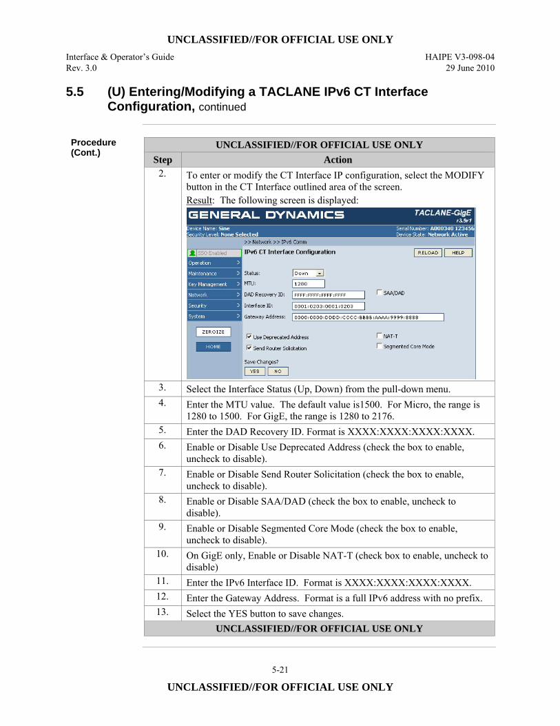
UNCLASSIFIED//FOR OFFICIAL USE ONLY Interface & Operator’s Guide HAIPE V3-098-04 Rev. 3.0 29 June 2010
5-21
UNCLASSIFIED//FOR OFFICIAL USE ONLY
5.5 (U) Entering/Modifying a TACLANE IPv6 CT Interface Configuration, continued
Procedure (Cont.)
UNCLASSIFIED//FOR OFFICIAL USE ONLY Step Action
2. To enter or modify the CT Interface IP configuration, select the MODIFY button in the CT Interface outlined area of the screen. Result: The following screen is displayed:
3. Select the Interface Status (Up, Down) from the pull-down menu. 4. Enter the MTU value. The default value is1500. For Micro, the range is
1280 to 1500. For GigE, the range is 1280 to 2176. 5. Enter the DAD Recovery ID. Format is XXXX:XXXX:XXXX:XXXX. 6. Enable or Disable Use Deprecated Address (check the box to enable,
uncheck to disable). 7. Enable or Disable Send Router Solicitation (check the box to enable,
uncheck to disable). 8. Enable or Disable SAA/DAD (check the box to enable, uncheck to
disable). 9. Enable or Disable Segmented Core Mode (check the box to enable,
uncheck to disable). 10. On GigE only, Enable or Disable NAT-T (check box to enable, uncheck to
disable) 11. Enter the IPv6 Interface ID. Format is XXXX:XXXX:XXXX:XXXX. 12. Enter the Gateway Address. Format is a full IPv6 address with no prefix. 13. Select the YES button to save changes.
UNCLASSIFIED//FOR OFFICIAL USE ONLY
UNCLASSIFIED//FOR OFFICIAL USE ONLY HAIPE V3-098-04 Interface & Operator’s Guide 29 June 2010 Rev. 3.0
5-22
UNCLASSIFIED//FOR OFFICIAL USE ONLY
5.6 (U) Entering/Modifying a TACLANE IPv6 CT Network Address
Introduction (U//FOUO) Through two levels of screens, the Operator configures the TACLANE
IPv6 Cipher Text (CT) interfaces as described in this section. (U//FOUO) The TACLANE supports manual configuration of: • CT Interface IPv6 Addresses 1 and 2
– Address/Prefix – Preferred Lifetime – Valid Lifetime
Notes (U//FOUO) The following notes apply to entering/modifying the TACLANE IP
addresses: • (U//FOUO) The CT IPv6 addresses must include the prefix length. • (U//FOUO) Any change to the IP network configuration will take effect
immediately following the acceptance of the change (upon selecting the YES button).
• (U//FOUO) Modifying or deleting an interface address will delete all configuration information referencing it, including Security Associations.
• (U//FOUO) The CT Addresses can be configured in the same or in different subnets as the PT Addresses.
• (U//FOUO) The CT IPv6 addresses must be unique such that no host or remote device (e.g., another TACLANE) uses these IP addresses.
• (U//FOUO) The Interface ID can be used to automatically form one of the CT Addresses (USE INTF ID button in Address Information box). If that is done, then a change to the Interface ID will cause the automatically formed Address to also change.
• (U//FOUO) If Duplicate Address Detection is enabled, then any manually configured address or Interface ID must pass Duplicate Address Detection before it can be assigned to the interface.
Continued on next page
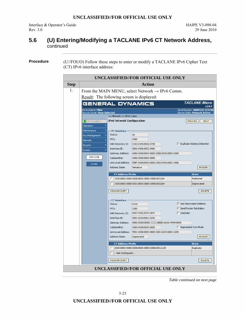
UNCLASSIFIED//FOR OFFICIAL USE ONLY Interface & Operator’s Guide HAIPE V3-098-04 Rev. 3.0 29 June 2010
5-23
UNCLASSIFIED//FOR OFFICIAL USE ONLY
5.6 (U) Entering/Modifying a TACLANE IPv6 CT Network Address, continued
Procedure (U//FOUO) Follow these steps to enter or modify a TACLANE IPv6 Cipher Text
(CT) IPv6 interface address:
UNCLASSIFIED//FOR OFFICIAL USE ONLY Step Action
1. From the MAIN MENU, select Network → IPv6 Comm. Result: The following screen is displayed:
UNCLASSIFIED//FOR OFFICIAL USE ONLY
Table continued on next page
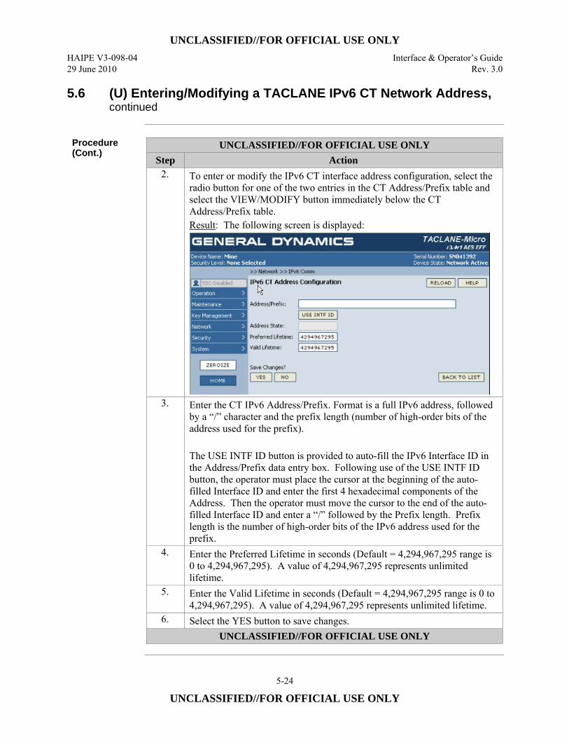
UNCLASSIFIED//FOR OFFICIAL USE ONLY HAIPE V3-098-04 Interface & Operator’s Guide 29 June 2010 Rev. 3.0
5-24
UNCLASSIFIED//FOR OFFICIAL USE ONLY
5.6 (U) Entering/Modifying a TACLANE IPv6 CT Network Address, continued
Procedure (Cont.)
UNCLASSIFIED//FOR OFFICIAL USE ONLY Step Action
2. To enter or modify the IPv6 CT interface address configuration, select the radio button for one of the two entries in the CT Address/Prefix table and select the VIEW/MODIFY button immediately below the CT Address/Prefix table. Result: The following screen is displayed:
3. Enter the CT IPv6 Address/Prefix. Format is a full IPv6 address, followed by a “/” character and the prefix length (number of high-order bits of the address used for the prefix). The USE INTF ID button is provided to auto-fill the IPv6 Interface ID in the Address/Prefix data entry box. Following use of the USE INTF ID button, the operator must place the cursor at the beginning of the auto-filled Interface ID and enter the first 4 hexadecimal components of the Address. Then the operator must move the cursor to the end of the auto-filled Interface ID and enter a “/” followed by the Prefix length. Prefix length is the number of high-order bits of the IPv6 address used for the prefix.
4. Enter the Preferred Lifetime in seconds (Default = 4,294,967,295 range is 0 to 4,294,967,295). A value of 4,294,967,295 represents unlimited lifetime.
5. Enter the Valid Lifetime in seconds (Default = 4,294,967,295 range is 0 to 4,294,967,295). A value of 4,294,967,295 represents unlimited lifetime.
6. Select the YES button to save changes. UNCLASSIFIED//FOR OFFICIAL USE ONLY
UNCLASSIFIED//FOR OFFICIAL USE ONLY Interface & Operator’s Guide HAIPE V3-098-04 Rev. 3.0 29 June 2010
5-25
UNCLASSIFIED//FOR OFFICIAL USE ONLY
5.7 (U) Deleting a TACLANE IPv6 Network Address
Introduction (U//FOUO) The Operator can manually delete a network address configured on a
TACLANE IPv6 Cipher Text (CT) interface or IPv6 Plain Text (PT) interface as described in this section. Either of the two network addresses assigned to an interface can be deleted without affecting the other assigned address.
Notes (U//FOUO) The following notes apply to deleting the TACLANE IP Network
Addresses: • (U//FOUO) Any change to the IP network configuration will take effect
immediately following the acceptance of the change (upon selecting the YES button).
• (U//FOUO) Deleting an interface address will delete all configuration information referencing it, including Security Associations.
Procedure (U//FOUO) Follow these steps to delete a TACLANE IPv6 Plain Text (PT) or
Cipher Text (CT) Interface Address:
Continued on next page
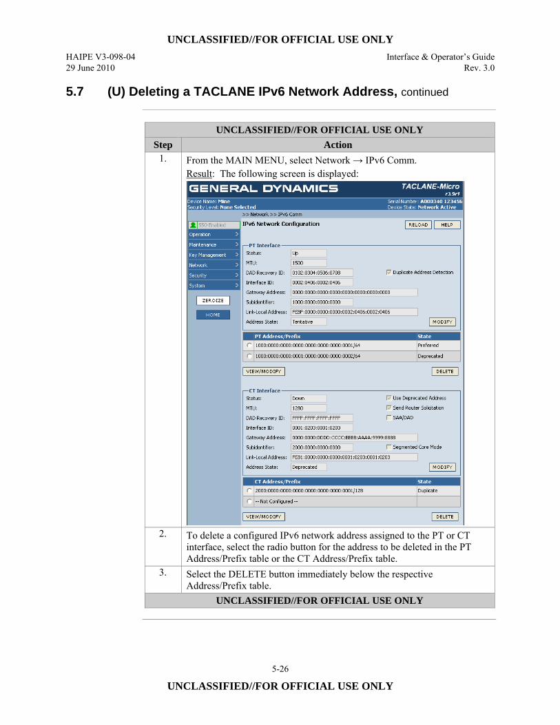
UNCLASSIFIED//FOR OFFICIAL USE ONLY HAIPE V3-098-04 Interface & Operator’s Guide 29 June 2010 Rev. 3.0
5-26
UNCLASSIFIED//FOR OFFICIAL USE ONLY
5.7 (U) Deleting a TACLANE IPv6 Network Address, continued
UNCLASSIFIED//FOR OFFICIAL USE ONLY
Step Action 1. From the MAIN MENU, select Network → IPv6 Comm.
Result: The following screen is displayed:
2. To delete a configured IPv6 network address assigned to the PT or CT interface, select the radio button for the address to be deleted in the PT Address/Prefix table or the CT Address/Prefix table.
3. Select the DELETE button immediately below the respective Address/Prefix table.
UNCLASSIFIED//FOR OFFICIAL USE ONLY
UNCLASSIFIED//FOR OFFICIAL USE ONLY Interface & Operator’s Guide HAIPE V3-098-04 Rev. 3.0 29 June 2010
5-27
UNCLASSIFIED//FOR OFFICIAL USE ONLY
5.8 (U) Configuring Control Message MTU Values
Introduction (U//FOUO) Through this screen, the Operator configures the TACLANE IPv4 and
IPv6 Control Message MTU settings for the network interfaces as described in this section. (U//FOUO) The TACLANE supports manual configuration that applies to both the CT and PT interfaces of: • IPv4 Control Message MTU
– Enable/Disable for IPv4 – MTU value for IPv4
• IPv6 Control Message MTU – Enable/Disable for IPv6 – MTU value for IPv6
Notes (U//FOUO) For IPv4 Control Messages, if a smaller MTU is required than for traffic
packets, then Enable Control Message MTU processing. Enter the Control Message MTU value (default = 1500, IPv4 range is 576 to 1500). If Control Messages do not require a smaller MTU, then Disable Control Message MTU processing. (U//FOUO) For IPv6 Control Messages, if a smaller MTU is required than for traffic packets, then Enable Control Message MTU processing. Enter the Control Message MTU value (default = 1500, range is 1280 to 1500). If Control Messages do not require a smaller MTU, then Disable Control Message MTU processing.
Continued on next page
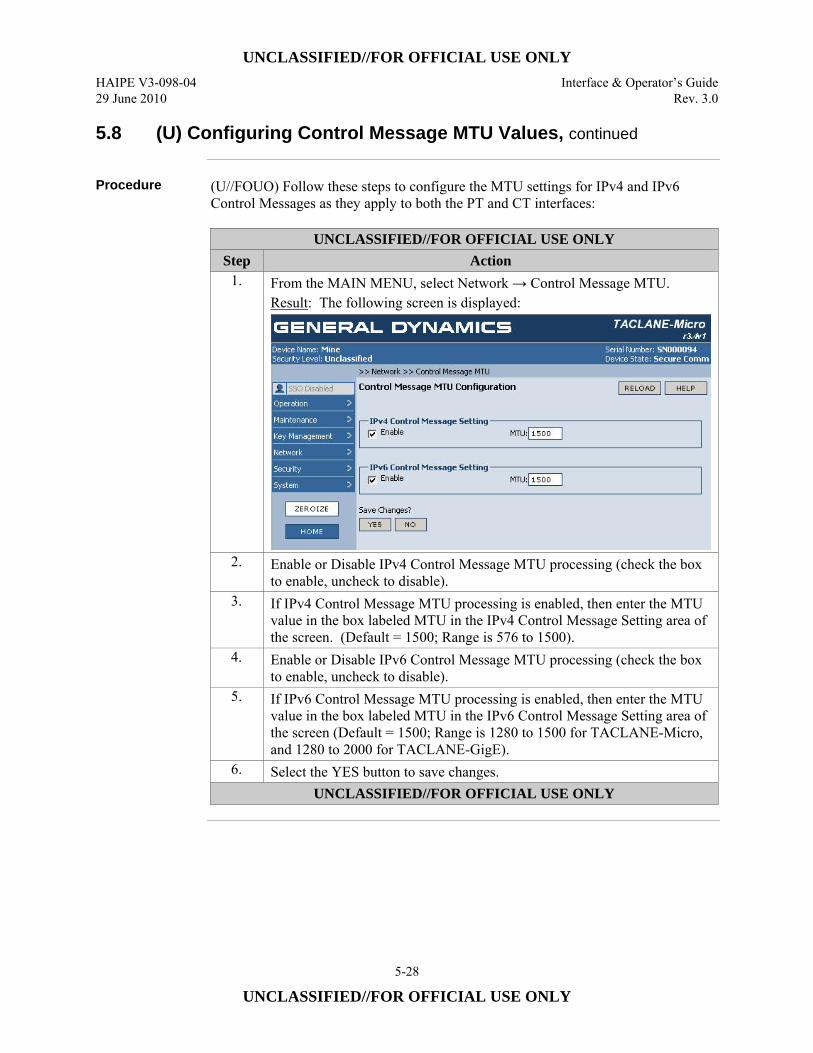
UNCLASSIFIED//FOR OFFICIAL USE ONLY HAIPE V3-098-04 Interface & Operator’s Guide 29 June 2010 Rev. 3.0
5-28
UNCLASSIFIED//FOR OFFICIAL USE ONLY
5.8 (U) Configuring Control Message MTU Values, continued
Procedure (U//FOUO) Follow these steps to configure the MTU settings for IPv4 and IPv6
Control Messages as they apply to both the PT and CT interfaces:
UNCLASSIFIED//FOR OFFICIAL USE ONLY Step Action
1. From the MAIN MENU, select Network → Control Message MTU. Result: The following screen is displayed:
2. Enable or Disable IPv4 Control Message MTU processing (check the box to enable, uncheck to disable).
3. If IPv4 Control Message MTU processing is enabled, then enter the MTU value in the box labeled MTU in the IPv4 Control Message Setting area of the screen. (Default = 1500; Range is 576 to 1500).
4. Enable or Disable IPv6 Control Message MTU processing (check the box to enable, uncheck to disable).
5. If IPv6 Control Message MTU processing is enabled, then enter the MTU value in the box labeled MTU in the IPv6 Control Message Setting area of the screen (Default = 1500; Range is 1280 to 1500 for TACLANE-Micro, and 1280 to 2000 for TACLANE-GigE).
6. Select the YES button to save changes. UNCLASSIFIED//FOR OFFICIAL USE ONLY
UNCLASSIFIED//FOR OFFICIAL USE ONLY Interface & Operator’s Guide HAIPE V3-098-04 Rev. 3.0 29 June 2010
5-29
UNCLASSIFIED//FOR OFFICIAL USE ONLY
5.9 (U) Creating PT-to-CT Address Mapping for Multicast Control Messages
Introduction (U//FOUO) The Operator creates Multicast address mappings for multicast control
messages as described in this section. There are two levels of HMI screens that are used to create a Multicast mapping for Control Messages. In the first screen the operator chooses to create a mapping. In the second screen the operator enters the mapping information. The TACLANE requires manual configuration of these PT-to-CT Multicast address mappings for Control Messages. Multicast mappings for traffic packets are manually entered in the >> Network >> Routing >> Peer Enclave screens as described in Sections 10.6 through 10.8.
Notes (U//FOUO) The following notes apply to creating the TACLANE IP address
mappings for Multicast Control Messages: • (U//FOUO To insure IGMP reports are issued immediately when the Discovery
multicast address is configured, configure the Solicitation Address Reception table and Multicast PPK SA before configuring the Multicast Mapping table. If the ECU is not configured in this order, multicast traffic for the Discovery multicast address could be delay until the next IGMP Query (typically 2 minutes) comes from the router.
• (U//FOUO) Address Mappings can be one-to-one or many-to-one (One PT address may map to one CT address or many PT addresses to one CT address).
• (U//FOUO) Both of the entered Multicast Addresses must be of the same IP version.
• (U//FOUO) The PT Addresses can be configured in the same or in different subnets as the CT Addresses.
• (U//FOUO) Only Multicast addresses are accepted for these address fields (IPv4: 224.0.0.0 to 239.255.255.255; and IPv6 FF00:: to FFFF::/8)
(U//FOUO) The following Multicast addresses are not accepted: • IPv4:
– 224.0.0.1 (All Systems) – 224.0.0.2 (All Routers) – 224.0.0.22 (All IGMPv3 Routes)
• IPv6: – FF01:: (Node Local Address) – FF02:: (Link Local Address)
(U//FOUO) The ECU can accept up to 500, Operator-created, Multicast Control Message Address Mapping entries. An additional 12 entries are reserved for well-known multicast mappings that are automatically configured and not displayed. (U//FOUO) Multicast Mode is set on the Security >> TFS screen, with IGMP Mode and Multicast Listener Discovery (MLD) Mode set separately. (U//FOUO) Multicast Version is set on the Network >> Multicast Versions screen.
Continued on next page
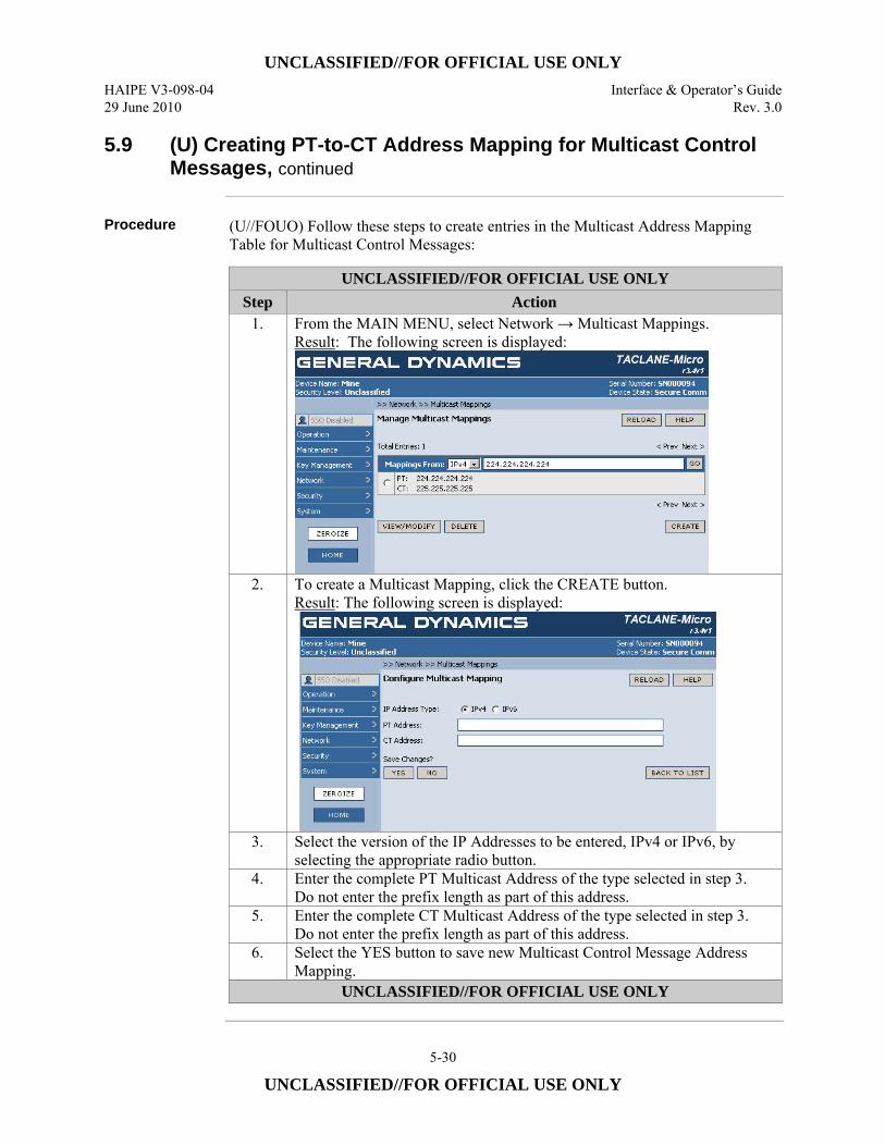
UNCLASSIFIED//FOR OFFICIAL USE ONLY HAIPE V3-098-04 Interface & Operator’s Guide 29 June 2010 Rev. 3.0
5-30
UNCLASSIFIED//FOR OFFICIAL USE ONLY
5.9 (U) Creating PT-to-CT Address Mapping for Multicast Control Messages, continued
Procedure (U//FOUO) Follow these steps to create entries in the Multicast Address Mapping
Table for Multicast Control Messages:
UNCLASSIFIED//FOR OFFICIAL USE ONLY Step Action
1. From the MAIN MENU, select Network → Multicast Mappings. Result: The following screen is displayed:
2. To create a Multicast Mapping, click the CREATE button.
Result: The following screen is displayed:
3. Select the version of the IP Addresses to be entered, IPv4 or IPv6, by selecting the appropriate radio button.
4. Enter the complete PT Multicast Address of the type selected in step 3. Do not enter the prefix length as part of this address.
5. Enter the complete CT Multicast Address of the type selected in step 3. Do not enter the prefix length as part of this address.
6. Select the YES button to save new Multicast Control Message Address Mapping.
UNCLASSIFIED//FOR OFFICIAL USE ONLY
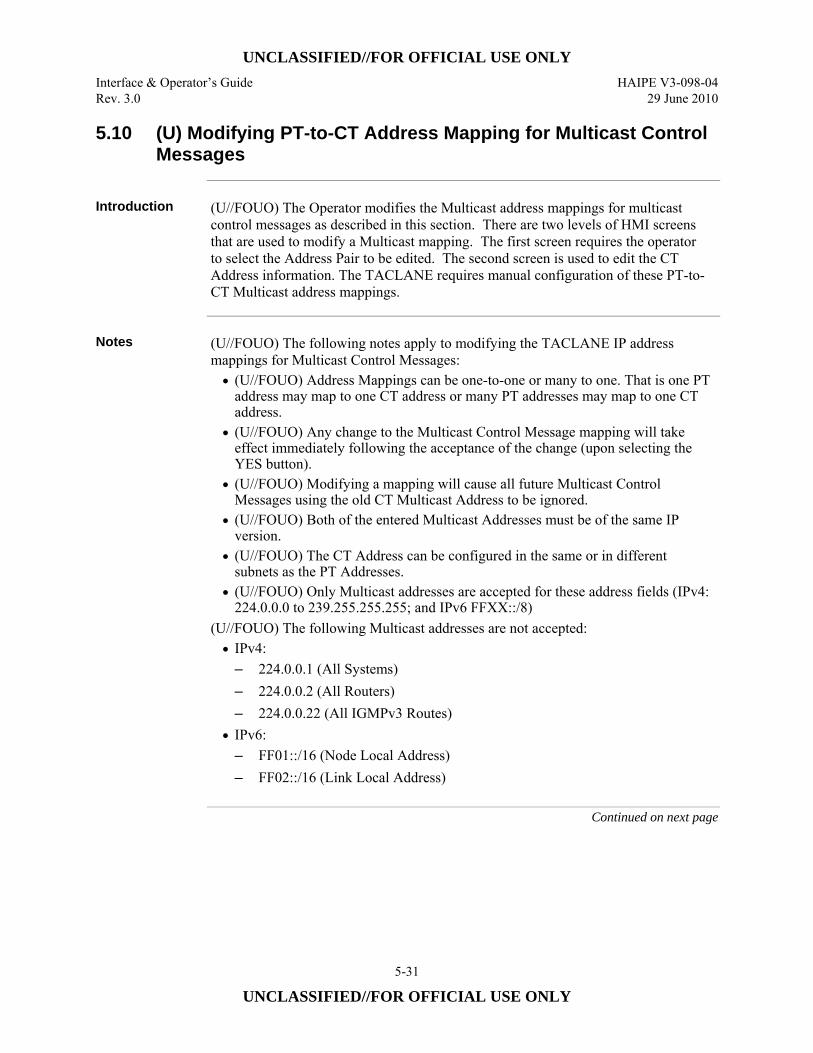
UNCLASSIFIED//FOR OFFICIAL USE ONLY Interface & Operator’s Guide HAIPE V3-098-04 Rev. 3.0 29 June 2010
5-31
UNCLASSIFIED//FOR OFFICIAL USE ONLY
5.10 (U) Modifying PT-to-CT Address Mapping for Multicast Control Messages
Introduction (U//FOUO) The Operator modifies the Multicast address mappings for multicast
control messages as described in this section. There are two levels of HMI screens that are used to modify a Multicast mapping. The first screen requires the operator to select the Address Pair to be edited. The second screen is used to edit the CT Address information. The TACLANE requires manual configuration of these PT-to-CT Multicast address mappings.
Notes (U//FOUO) The following notes apply to modifying the TACLANE IP address
mappings for Multicast Control Messages: • (U//FOUO) Address Mappings can be one-to-one or many to one. That is one PT
address may map to one CT address or many PT addresses may map to one CT address.
• (U//FOUO) Any change to the Multicast Control Message mapping will take effect immediately following the acceptance of the change (upon selecting the YES button).
• (U//FOUO) Modifying a mapping will cause all future Multicast Control Messages using the old CT Multicast Address to be ignored.
• (U//FOUO) Both of the entered Multicast Addresses must be of the same IP version.
• (U//FOUO) The CT Address can be configured in the same or in different subnets as the PT Addresses.
• (U//FOUO) Only Multicast addresses are accepted for these address fields (IPv4: 224.0.0.0 to 239.255.255.255; and IPv6 FFXX::/8)
(U//FOUO) The following Multicast addresses are not accepted: • IPv4:
– 224.0.0.1 (All Systems) – 224.0.0.2 (All Routers) – 224.0.0.22 (All IGMPv3 Routes)
• IPv6: – FF01::/16 (Node Local Address) – FF02::/16 (Link Local Address)
Continued on next page
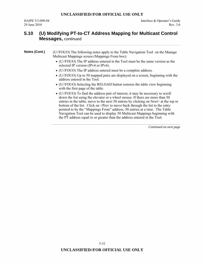
UNCLASSIFIED//FOR OFFICIAL USE ONLY HAIPE V3-098-04 Interface & Operator’s Guide 29 June 2010 Rev. 3.0
5-32
UNCLASSIFIED//FOR OFFICIAL USE ONLY
5.10 (U) Modifying PT-to-CT Address Mapping for Multicast Control Messages, continued
Notes (Cont.) (U//FOUO) The following notes apply to the Table Navigation Tool on the Manage
Multicast Mappings screen (Mappings From box): • (U//FOUO) The IP address entered in the Tool must be the same version as the
selected IP version (IPv4 or IPv6). • (U//FOUO) The IP address entered must be a complete address. • (U//FOUO) Up to 50 mapped pairs are displayed on a screen, beginning with the
address entered in the Tool. • (U//FOUO) Selecting the RELOAD button restores the table view beginning
with the first page of the table. • (U//FOUO) To find the address pair of interest, it may be necessary to scroll
down the list using the elevator or a wheel mouse. If there are more than 50 entries in the table, move to the next 50 entries by clicking on Next> at the top or bottom of the list. Click on <Prev to move back through the list to the entry pointed to by the “Mappings From” address, 50 entries at a time. The Table Navigation Tool can be used to display 50 Multicast Mappings beginning with the PT address equal to or greater than the address entered in the Tool.
Continued on next page
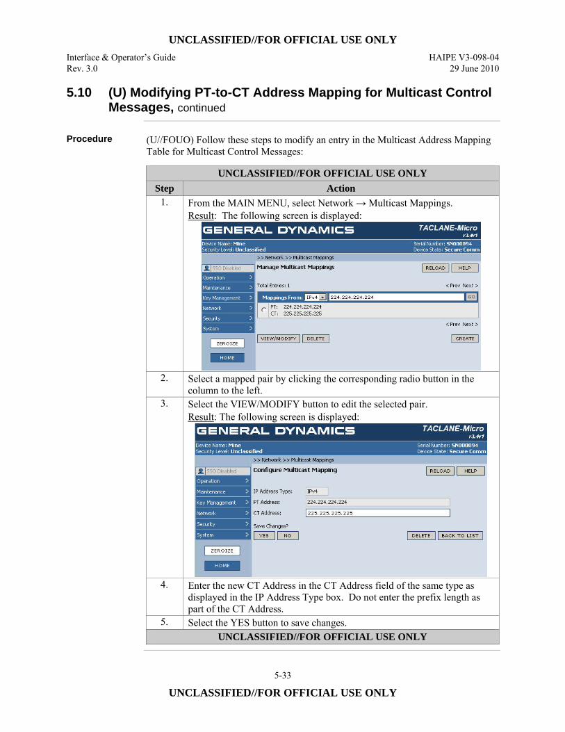
UNCLASSIFIED//FOR OFFICIAL USE ONLY Interface & Operator’s Guide HAIPE V3-098-04 Rev. 3.0 29 June 2010
5-33
UNCLASSIFIED//FOR OFFICIAL USE ONLY
5.10 (U) Modifying PT-to-CT Address Mapping for Multicast Control Messages, continued
Procedure (U//FOUO) Follow these steps to modify an entry in the Multicast Address Mapping
Table for Multicast Control Messages:
UNCLASSIFIED//FOR OFFICIAL USE ONLY Step Action
1. From the MAIN MENU, select Network → Multicast Mappings. Result: The following screen is displayed:
2. Select a mapped pair by clicking the corresponding radio button in the column to the left.
3. Select the VIEW/MODIFY button to edit the selected pair. Result: The following screen is displayed:
4. Enter the new CT Address in the CT Address field of the same type as displayed in the IP Address Type box. Do not enter the prefix length as part of the CT Address.
5. Select the YES button to save changes. UNCLASSIFIED//FOR OFFICIAL USE ONLY
UNCLASSIFIED//FOR OFFICIAL USE ONLY HAIPE V3-098-04 Interface & Operator’s Guide 29 June 2010 Rev. 3.0
5-34
UNCLASSIFIED//FOR OFFICIAL USE ONLY
5.11 (U) Deleting PT-to-CT Mapped Address Pair for Multicast Control Messages
Introduction (U//FOUO) The Operator deletes a Multicast address mapping for multicast control
messages as described in this section. The delete is done on the Manage Multicast Mappings screen. The TACLANE requires manual configuration of PT-to-CT address mappings for Multicast Control Messages.
Notes (U//FOUO) The following notes apply to deleting a TACLANE IP address mapping
for Multicast Control Messages: (U//FOUO) Deleting a mapping will cause all future Multicast Control Messages using the old Multicast Address Mapping to be ignored. (U//FOUO) The following notes apply to the Table Navigation Tool on the Manage Multicast Mappings screen (Mappings From box): • (U//FOUO) The IP address entered in the Tool must be the same version as the
selected IP version (IPv4 or IPv6). • (U//FOUO) The IP address entered must be a complete address. • (U//FOUO) Up to 50 mapped pairs are displayed on a screen, beginning with the
address entered in the Tool. • (U//FOUO) Selecting the RELOAD button restores the table view beginning
with the first page of the table. • (U//FOUO) To find the address pair of interest, it may be necessary to scroll
down the list using the elevator or a wheel mouse. If there are more than 50 entries in the table, move to the next 50 entries by clicking on Next> at the top or bottom of the list. Click on <Prev to move back through the list to the entry pointed to by the “Mappings From” address, 50 entries at a time. The Table Navigation Tool can be used to display 50 Multicast Mappings beginning with the PT address equal to or greater than the address entered in the Tool.
Continued on next page
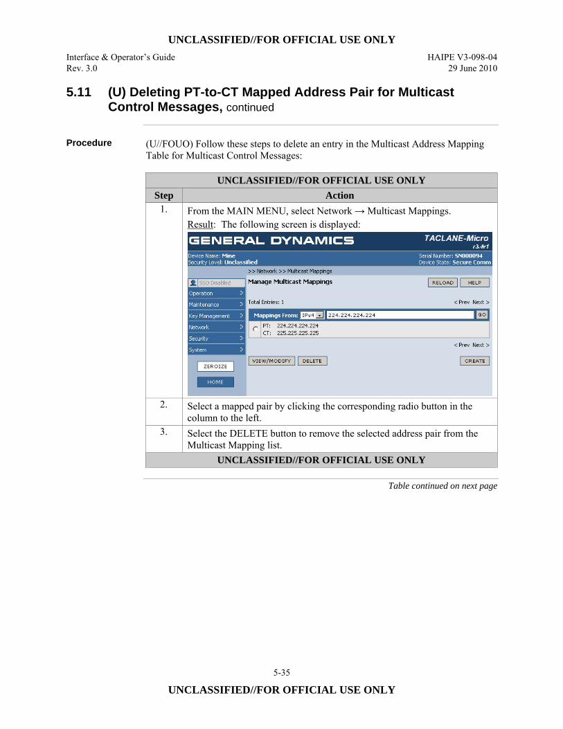
UNCLASSIFIED//FOR OFFICIAL USE ONLY Interface & Operator’s Guide HAIPE V3-098-04 Rev. 3.0 29 June 2010
5-35
UNCLASSIFIED//FOR OFFICIAL USE ONLY
5.11 (U) Deleting PT-to-CT Mapped Address Pair for Multicast Control Messages, continued
Procedure (U//FOUO) Follow these steps to delete an entry in the Multicast Address Mapping
Table for Multicast Control Messages:
UNCLASSIFIED//FOR OFFICIAL USE ONLY Step Action
1. From the MAIN MENU, select Network → Multicast Mappings. Result: The following screen is displayed:
2. Select a mapped pair by clicking the corresponding radio button in the column to the left.
3. Select the DELETE button to remove the selected address pair from the Multicast Mapping list.
UNCLASSIFIED//FOR OFFICIAL USE ONLY
Table continued on next page
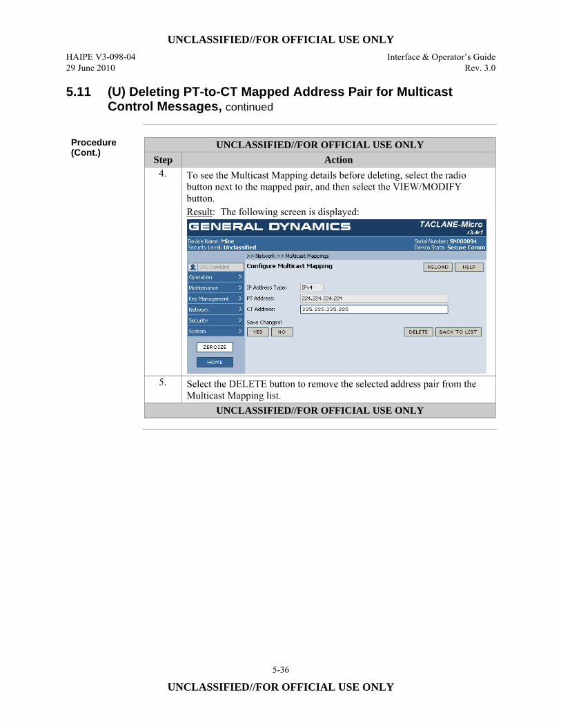
UNCLASSIFIED//FOR OFFICIAL USE ONLY HAIPE V3-098-04 Interface & Operator’s Guide 29 June 2010 Rev. 3.0
5-36
UNCLASSIFIED//FOR OFFICIAL USE ONLY
5.11 (U) Deleting PT-to-CT Mapped Address Pair for Multicast Control Messages, continued
Procedure (Cont.)
UNCLASSIFIED//FOR OFFICIAL USE ONLY Step Action
4. To see the Multicast Mapping details before deleting, select the radio button next to the mapped pair, and then select the VIEW/MODIFY button. Result: The following screen is displayed:
5. Select the DELETE button to remove the selected address pair from the Multicast Mapping list.
UNCLASSIFIED//FOR OFFICIAL USE ONLY
UNCLASSIFIED//FOR OFFICIAL USE ONLY Interface & Operator’s Guide HAIPE V3-098-04 Rev. 3.0 29 June 2010
5-37
UNCLASSIFIED//FOR OFFICIAL USE ONLY
5.12 (U) Displaying PT-to-CT Address Mapping for Multicast Control Messages
Introduction (U//FOUO) The Operator displays Multicast address mappings for multicast control
messages as described in this section. There are two levels of HMI screens that display Multicast mapping. In the first screen the operator views up to 50 address pairs, or can choose a single mapped address pair to display (and modify – see Section 5.10). In the second screen, the operator views the mapping information for a single address pair.
Notes (U//FOUO) The following notes apply to displaying the TACLANE IP address
mappings for Multicast Control Messages: • (U//FOUO) The global Multicast Mode is displayed on the Security >> TFS
screen, with IGMP Mode and MLD Mode set separately. (U//FOUO) The ECU can accept up to 500, Operator-created, Multicast Control Message Address Mapping entries. An additional 12 entries are reserved for well-known multicast mappings that are automatically configured and not displayed. (U//FOUO) The following notes apply to the Table Navigation Tool on the Manage Multicast Mappings screen (Mappings From box): • (U//FOUO) The IP address entered in the Tool must be the same version as the
selected IP version (IPv4 or IPv6). • (U//FOUO) The IP address entered must be a complete address. • (U//FOUO) Up to 50 mapped pairs are displayed on a screen, beginning with the
address entered in the Tool. • (U//FOUO) Selecting the RELOAD button restores the table view beginning
with the first page of the table. • (U//FOUO) To find the address pair of interest, it may be necessary to scroll
down the list using the elevator or a wheel mouse. If there are more than 50 entries in the table, move to the next 50 entries by clicking on Next> at the top or bottom of the list. Click on <Prev to move back through the list to the entry pointed to by the “Mappings From” address, 50 entries at a time. The Table Navigation Tool can be used to display 50 Multicast Mappings beginning with the PT address equal to or greater than the address entered in the Tool.
Continued on next page
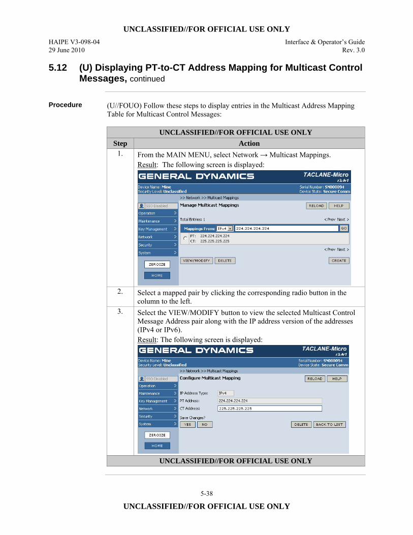
UNCLASSIFIED//FOR OFFICIAL USE ONLY HAIPE V3-098-04 Interface & Operator’s Guide 29 June 2010 Rev. 3.0
5-38
UNCLASSIFIED//FOR OFFICIAL USE ONLY
5.12 (U) Displaying PT-to-CT Address Mapping for Multicast Control Messages, continued
Procedure (U//FOUO) Follow these steps to display entries in the Multicast Address Mapping
Table for Multicast Control Messages:
UNCLASSIFIED//FOR OFFICIAL USE ONLY Step Action
1. From the MAIN MENU, select Network → Multicast Mappings. Result: The following screen is displayed:
2. Select a mapped pair by clicking the corresponding radio button in the column to the left.
3. Select the VIEW/MODIFY button to view the selected Multicast Control Message Address pair along with the IP address version of the addresses (IPv4 or IPv6). Result: The following screen is displayed:
UNCLASSIFIED//FOR OFFICIAL USE ONLY
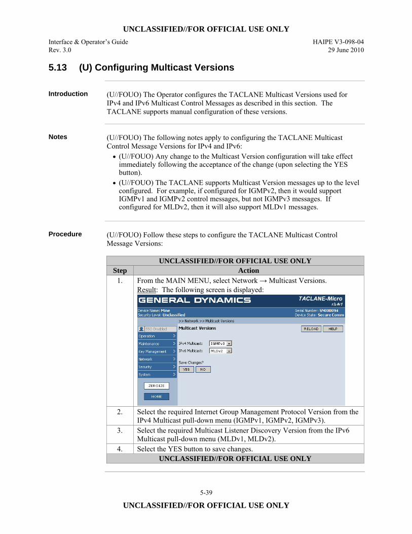
UNCLASSIFIED//FOR OFFICIAL USE ONLY Interface & Operator’s Guide HAIPE V3-098-04 Rev. 3.0 29 June 2010
5-39
UNCLASSIFIED//FOR OFFICIAL USE ONLY
5.13 (U) Configuring Multicast Versions
Introduction (U//FOUO) The Operator configures the TACLANE Multicast Versions used for
IPv4 and IPv6 Multicast Control Messages as described in this section. The TACLANE supports manual configuration of these versions.
Notes (U//FOUO) The following notes apply to configuring the TACLANE Multicast
Control Message Versions for IPv4 and IPv6: • (U//FOUO) Any change to the Multicast Version configuration will take effect
immediately following the acceptance of the change (upon selecting the YES button).
• (U//FOUO) The TACLANE supports Multicast Version messages up to the level configured. For example, if configured for IGMPv2, then it would support IGMPv1 and IGMPv2 control messages, but not IGMPv3 messages. If configured for MLDv2, then it will also support MLDv1 messages.
Procedure (U//FOUO) Follow these steps to configure the TACLANE Multicast Control
Message Versions:
UNCLASSIFIED//FOR OFFICIAL USE ONLY Step Action
1. From the MAIN MENU, select Network → Multicast Versions. Result: The following screen is displayed:
2. Select the required Internet Group Management Protocol Version from the IPv4 Multicast pull-down menu (IGMPv1, IGMPv2, IGMPv3).
3. Select the required Multicast Listener Discovery Version from the IPv6 Multicast pull-down menu (MLDv1, MLDv2).
4. Select the YES button to save changes. UNCLASSIFIED//FOR OFFICIAL USE ONLY
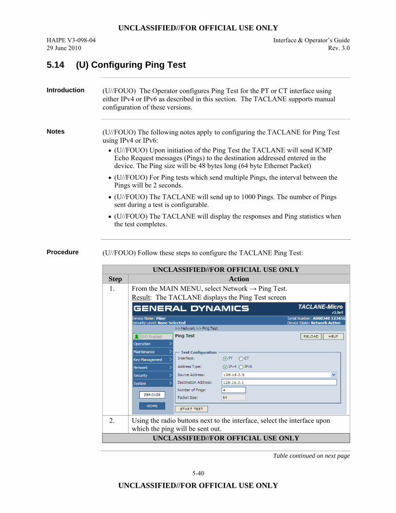
UNCLASSIFIED//FOR OFFICIAL USE ONLY HAIPE V3-098-04 Interface & Operator’s Guide 29 June 2010 Rev. 3.0
5-40
UNCLASSIFIED//FOR OFFICIAL USE ONLY
5.14 (U) Configuring Ping Test
Introduction (U//FOUO) The Operator configures Ping Test for the PT or CT interface using
either IPv4 or IPv6 as described in this section. The TACLANE supports manual configuration of these versions.
Notes (U//FOUO) The following notes apply to configuring the TACLANE for Ping Test
using IPv4 or IPv6: • (U//FOUO) Upon initiation of the Ping Test the TACLANE will send ICMP
Echo Request messages (Pings) to the destination addressed entered in the device. The Ping size will be 48 bytes long (64 byte Ethernet Packet)
• (U//FOUO) For Ping tests which send multiple Pings, the interval between the Pings will be 2 seconds.
• (U//FOUO) The TACLANE will send up to 1000 Pings. The number of Pings sent during a test is configurable.
• (U//FOUO) The TACLANE will display the responses and Ping statistics when the test completes.
Procedure (U//FOUO) Follow these steps to configure the TACLANE Ping Test:
UNCLASSIFIED//FOR OFFICIAL USE ONLY Step Action 1. From the MAIN MENU, select Network → Ping Test.
Result: The TACLANE displays the Ping Test screen
2. Using the radio buttons next to the interface, select the interface upon which the ping will be sent out.
UNCLASSIFIED//FOR OFFICIAL USE ONLY
Table continued on next page
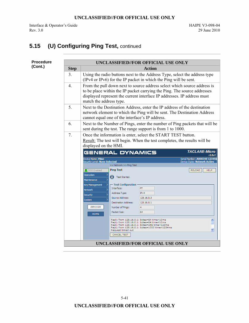
UNCLASSIFIED//FOR OFFICIAL USE ONLY Interface & Operator’s Guide HAIPE V3-098-04 Rev. 3.0 29 June 2010
5-41
UNCLASSIFIED//FOR OFFICIAL USE ONLY
5.15 (U) Configuring Ping Test, continued
Procedure (Cont.)
UNCLASSIFIED//FOR OFFICIAL USE ONLY Step Action 3. Using the radio buttons next to the Address Type, select the address type
(IPv4 or IPv6) for the IP packet in which the Ping will be sent. 4. From the pull down next to source address select which source address is
to be place within the IP packet carrying the Ping. The source addresses displayed represent the current interface IP addresses. IP address must match the address type.
5. Next to the Destination Address, enter the IP address of the destination network element to which the Ping will be sent. The Destination Address cannot equal one of the interface’s IP address.
6. Next to the Number of Pings, enter the number of Ping packets that will be sent during the test. The range support is from 1 to 1000.
7. Once the information is enter, select the START TEST button. Result: The test will begin. When the test completes, the results will be displayed on the HMI.
UNCLASSIFIED//FOR OFFICIAL USE ONLY

UNCLASSIFIED//FOR OFFICIAL USE ONLY HAIPE V3-098-04 Interface & Operator’s Guide 29 June 2010 Rev. 3.0
5-42
UNCLASSIFIED//FOR OFFICIAL USE ONLY
(U) This page intentionally left blank.
UNCLASSIFIED//FOR OFFICIAL USE ONLY Interface & Operator’s Guide HAIPE V3-098-04 Rev. 3.0 29 June 2010
6-1
UNCLASSIFIED//FOR OFFICIAL USE ONLY
6.0 (U) CONFIGURING IP TRAFFIC FLOW SECURITY PARAMETERS
General Notes (U//FOUO) The TACLANE includes IP Traffic Flow Security (TFS) features that
are required by the HAIPE IS Traffic Flow Security specification. When configured appropriately, the IP TFS features in the TACLANE prevent/reduce compromise of sensitive information due to certain types of attacks. This chapter explains how each IP TFS parameter may be configured by the Site Security Officer (SSO) and how the IP TFS configuration information can be displayed. (U//FOUO) There are important security and performance trade-offs that should be considered when enabling and disabling TFS countermeasures. For descriptions of these trade-offs along with recommended network and equipment configurations that minimize security risks, please refer to the TACLANE Security Features Users Guide. (U//FOUO) TFS configuration update has been extended to allow online updates of TFS parameters. Although the design permits this, there is a slight chance that a false alarm may be detected when traffic loading is over 10 Mbps. Therefore it is recommended not to change TFS parameters during high traffic periods. If the false alarm is detected, the TACLANE will restart and recover with the new configuration.
6.1 (U) Configuring Fixed Packet Length Parameters
Introduction (U//FOUO) Fixed Packet Length (FPL) parameters can be configured only by the
SSO. The purpose of Fixed Packet Length processing is to obscure the sizes of plaintext IP packets before they are encrypted and transmitted on the CT network. When FPL processing is enabled, all user data packets (including IP multicast datagrams) received on the PT side of the TACLANE are padded to a fixed length if shorter than the configured fixed length or fragmented if longer than the configured fixed length. Fixed Packet Length parameters do not affect the processing of IP packets received on the CT side. All the TACLANE software versions correctly discard the padding added by FPL processing. Fixed Packet Length configuration has no impact on interoperability; FPL parameters can be configured independently at each TACLANE.
Notes (U//FOUO) The following notes apply to configuring Fixed Packet Length
parameters: • Only the SSO has the privilege to configure FPL parameters.
Continued on next page
UNCLASSIFIED//FOR OFFICIAL USE ONLY HAIPE V3-098-04 Interface & Operator’s Guide 29 June 2010 Rev. 3.0
6-2
UNCLASSIFIED//FOR OFFICIAL USE ONLY
6.1 (U) Configuring Fixed Packet Length Parameters, continued
Fixed Packet Length Parameters
(U//FOUO) The following two Fixed Packet Length parameters can be configured by the SSO: • (U//FOUO) Mode: The FPL mode can be set to: ON or OFF. When the mode is
set to ON, FPL processing is performed. Incoming PT user data packets are fragmented if the resultant outgoing ESP packets at the CT interface would be longer than the configured FPL. All ESP packets will be equal to the fixed packet length, with the last fragment being padded as necessary. When the mode is set to OFF, no FPL processing is done. The default value is OFF.
• (U//FOUO) Length: This is the ESP packet length (sum of the IP header and the payload outgoing from the CT interface), in bytes. All incoming PT user data packets are padded or fragmented such that the resultant ESP packets have this length.
– For the TACLANE-Micro, the fixed packet length can be set to any one of 26 values ranging from 216 to 1416, in increments of 48. The default value is 792.
• For the TACLANE-GigE, the fixed packet length can be set to any one of 36 values ranging from 216 to 2136 in increments of 48. The default value is 792.
Fixed Packet Length Processing
(U//FOUO) When the fixed packet mode is set to ON: • (U//FOUO) Incoming PT IP user data packets longer than the fixed packet length
are fragmented. All fragments will be equal to the fixed packet length, with fragments being padded if necessary. (See the SFUG for more details on fragmentation.)
• (U//FOUO) Incoming PT IP user data packets shorter than the fixed packet length are padded to the fixed packet length.
(U//FOUO) When the fixed packet mode is set to OFF (default setting): • (U//FOUO) No fixed packet processing is done.
(U//FOUO) Once the CT traffic is decrypted by the receiving TACLANE: • (U//FOUO) Any padding that was added by the encrypting TACLANE is
discarded. • (U//FOUO) No reassembly of plaintext fragments is done. All decrypted
fragments are sent to destination hosts for reassembly. • (U//FOUO) This receive processing is the same for all TACLANE software
versions.
(U//FOUO) Note: Fixed Packet Length processing applies to all ESP IP datagrams, including IP multicast datagrams. Control messages such as IGMP are not affected by FPL processing.
Continued on next page
UNCLASSIFIED//FOR OFFICIAL USE ONLY Interface & Operator’s Guide HAIPE V3-098-04 Rev. 3.0 29 June 2010
6-3
UNCLASSIFIED//FOR OFFICIAL USE ONLY
6.1 (U) Configuring Fixed Packet Length Parameters, continued
FPL and MTU (U//FOUO) When configuring the FPL and MTU parameters, it is important to
consider their effects on TACLANE processing. Improper configurations can cause excessive fragmentation, which will have a negative impact on performance. (U//FOUO) When FPL processing is enabled, the fixed packet length affects the size of packets prior to encryption. When necessary, fragmentation is performed on plaintext datagrams. Since each fragment is encrypted separately, no reassembly is performed by the destination TACLANE. Each fragment is decrypted and sent to its PT destination host. Reassembly of fragments created because of FPL processing is performed by destination hosts. (U//FOUO) In contrast, the TL MTU determines which packets are fragmented following encryption. Since MTU fragmentation is performed on encrypted packets, the fragments must be received and reassembled by the destination TACLANE before each packet can be decrypted. If the MTU is not set to at least 70 bytes more than the FPL, then every packet may be fragmented on the CT side, causing severe performance degradation. For information on configuring the MTU size, see Sections on “Entering/Modifying the TACLANE IPv4 Network Configuration,” “Entering/Modifying a TACLANE IPv6 PT Interface Configuration,” and “Entering/Modifying a TACLANE IPv6 CT Interface Configuration.”
FPL and Transport Mode
(U//FOUO) Transport Mode SAs are not supported, if FPL processing is enabled. (U//FOUO) Transport Mode FIREFLY SA Templates, Transport Mode FIREFLY SAs and Transport Mode PPK SAs cannot be created, if FPL is enabled. (U//FOUO) All existing Transport Mode FIREFLY SA Templates, Transport Mode FIREFLY SAs and Transport Mode PPK SAs will be terminated when FPL is enabled.
Continued on next page
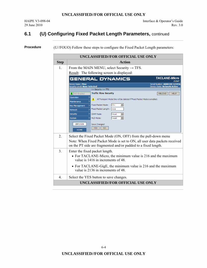
UNCLASSIFIED//FOR OFFICIAL USE ONLY HAIPE V3-098-04 Interface & Operator’s Guide 29 June 2010 Rev. 3.0
6-4
UNCLASSIFIED//FOR OFFICIAL USE ONLY
6.1 (U) Configuring Fixed Packet Length Parameters, continued
Procedure (U//FOUO) Follow these steps to configure the Fixed Packet Length parameters:
UNCLASSIFIED//FOR OFFICIAL USE ONLY Step Action
1. From the MAIN MENU, select Security → TFS. Result: The following screen is displayed:
2. Select the Fixed Packet Mode (ON, OFF) from the pull-down menu Note: When Fixed Packet Mode is set to ON, all user data packets received on the PT side are fragmented and/or padded to a fixed length.
3. Enter the fixed packet length. • For TACLANE-Micro, the minimum value is 216 and the maximum
value is 1416 in increments of 48. • For TACLANE-GigE, the minimum value is 216 and the maximum
value is 2136 in increments of 48.
4. Select the YES button to save changes. UNCLASSIFIED//FOR OFFICIAL USE ONLY
UNCLASSIFIED//FOR OFFICIAL USE ONLY Interface & Operator’s Guide HAIPE V3-098-04 Rev. 3.0 29 June 2010
6-5
UNCLASSIFIED//FOR OFFICIAL USE ONLY
6.2 (U) Configuring IGMP Mode
Introduction (U//FOUO) The Internet Group Management Protocol (IGMP) is the protocol used
by IPv4 systems to report their IP multicast group memberships to neighboring multicast routers. IGMP messages provide IP multicast message delivery to host group IP addresses (224.0.0.0 to 239.255.255.255). (U//FOUO) The TACLANE’s IGMP Mode parameter, configurable as Host or Bypass, determines how the TACLANE will handle IGMP traffic for user multicast traffic.
Notes (U//FOUO) The following notes apply to configuring the IGMP Mode parameter:
• (U//FOUO) Only the SSO has the privilege to configure the IGMP bypass parameter.
• (U//FOUO) An audit log entry is generated when the IGMP bypass parameter is modified.
IGMP Mode Parameter and Processing
(U//FOUO) When the IGMP Mode is Bypass, the TACLANE does not encrypt PT IGMP messages as user multicast traffic. When the IGMP Mode is Bypass, the TACLANE regenerates user IGMP messages traveling from both CT-to-PT as well as from PT-to-CT for multicast addresses which have established Security Associations and Multicast Mapping Table entries associated with them. General Queries are regenerated as well. (U//FOUO) When the IGMP Mode is Host, the TACLANE does not perform IGMP Regeneration. Rather, it acts as a host, independently on the PT and CT interfaces. In IGMP Host Mode both the CT and PT interface respond to IGMP Queries with IGMP Reports containing multicast addresses which have established Security Associations and associated entries in the Multicast Mapping Table. (U//FOUO) The default for the IGMP Mode parameter is Host. (U//FOUO) Refer to Appendix B of the Operator’s Manual for more details on IGMP configuration. (U//FOUO) Note that the TACLANE also supports IGMP on the CT side in order to support the HAIPE IS Secure Dynamic Discovery (SDD) multicast traffic. The IGMP Mode parameter, however, has no effect on the TACLANE’s IGMP support for SDD traffic. Regardless of whether the IGMP Mode parameter is Bypass or Host, the TACLANE will support IGMP for SDD traffic whenever the SDD multicast group is configured (i.e., assigned to the SDD PPK).
Continued on next page
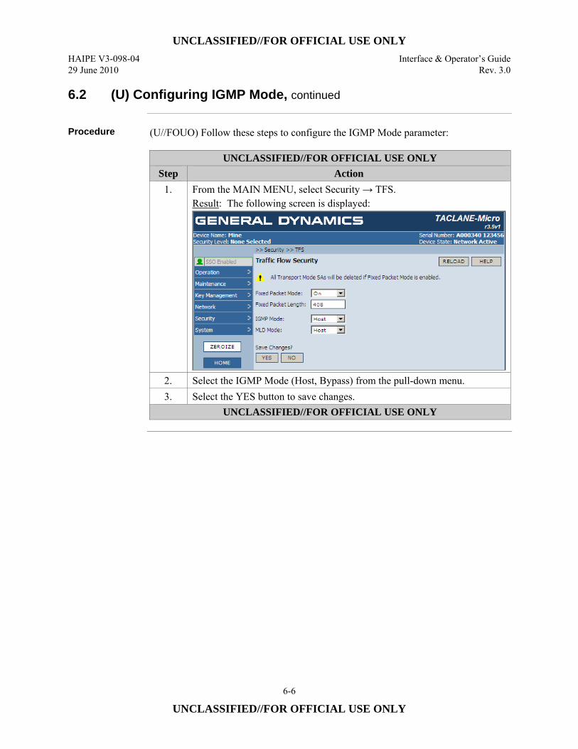
UNCLASSIFIED//FOR OFFICIAL USE ONLY HAIPE V3-098-04 Interface & Operator’s Guide 29 June 2010 Rev. 3.0
6-6
UNCLASSIFIED//FOR OFFICIAL USE ONLY
6.2 (U) Configuring IGMP Mode, continued
Procedure (U//FOUO) Follow these steps to configure the IGMP Mode parameter:
UNCLASSIFIED//FOR OFFICIAL USE ONLY Step Action
1. From the MAIN MENU, select Security → TFS. Result: The following screen is displayed:
2. Select the IGMP Mode (Host, Bypass) from the pull-down menu. 3. Select the YES button to save changes.
UNCLASSIFIED//FOR OFFICIAL USE ONLY
UNCLASSIFIED//FOR OFFICIAL USE ONLY Interface & Operator’s Guide HAIPE V3-098-04 Rev. 3.0 29 June 2010
6-7
UNCLASSIFIED//FOR OFFICIAL USE ONLY
6.3 (U) Configuring MLD Mode
Introduction (U//FOUO) The Multicast Listener Discovery (MLD) is the protocol used by IPv6
systems to report their IP multicast group memberships to neighboring multicast routers. MLD messages provide IP multicast message delivery to host group IP addresses (FF00::/8). (U//FOUO) The TACLANE’s MLD parameter, configurable as Host or Bypass, determines whether the TACLANE will regenerate MLD traffic for user multicast traffic.
Notes (U//FOUO) The following notes apply to configuring the MLD Mode parameter:
• (U//FOUO) Only the SSO has the privilege to configure the MLD bypass parameter.
• (U//FOUO) An audit log entry is generated when the MLD bypass parameter is modified.
MLD Mode Parameter and Processing
(U//FOUO) When the MLD Mode is Bypass, the TACLANE does not encrypt PT MLD messages as user multicast traffic. When the MLD Mode is Bypass, the TACLANE regenerates user MLD messages traveling from both CT-to-PT as well as from PT-to-CT for multicast addresses which have established Security Associations and Multicast Mapping Table entries associated with them. General Queries are regenerated as well (U//FOUO) When the MLD Mode is Host, the TACLANE does not perform MLD Regeneration. Rather, it acts as a host, independently on the PT and CT interfaces. In MLD Host Mode both the CT and PT interface respond to MLD Queries with MLD Reports containing multicast addresses which have established Security Associations and associated entries in the Multicast Mapping Table. (U//FOUO) The default for the MLD Mode parameter is Host. (U//FOUO) Refer to Appendix B of the Operator’s Manual for more details on MLD configuration.
Continued on next page

UNCLASSIFIED//FOR OFFICIAL USE ONLY HAIPE V3-098-04 Interface & Operator’s Guide 29 June 2010 Rev. 3.0
6-8
UNCLASSIFIED//FOR OFFICIAL USE ONLY
6.3 (U) Configuring MLD Mode, continued
Procedure (U//FOUO) Follow these steps to configure the MLD Mode parameter:
UNCLASSIFIED//FOR OFFICIAL USE ONLY Step Action
1. From the MAIN MENU, select Security → TFS. Result: The following screen is displayed:
2. Select the MLD Mode (Host, Bypass) from the pull-down menu 3. Select the YES button to save changes.
UNCLASSIFIED//FOR OFFICIAL USE ONLY
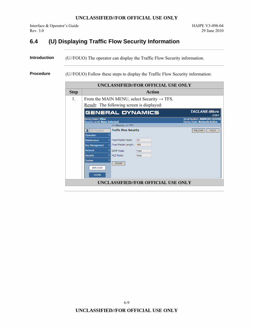
UNCLASSIFIED//FOR OFFICIAL USE ONLY Interface & Operator’s Guide HAIPE V3-098-04 Rev. 3.0 29 June 2010
6-9
UNCLASSIFIED//FOR OFFICIAL USE ONLY
6.4 (U) Displaying Traffic Flow Security Information
Introduction (U//FOUO) The operator can display the Traffic Flow Security information.
Procedure (U//FOUO) Follow these steps to display the Traffic Flow Security information:
UNCLASSIFIED//FOR OFFICIAL USE ONLY Step Action
1. From the MAIN MENU, select Security → TFS. Result: The following screen is displayed:
UNCLASSIFIED//FOR OFFICIAL USE ONLY

UNCLASSIFIED//FOR OFFICIAL USE ONLY HAIPE V3-098-04 Interface & Operator’s Guide 29 June 2010 Rev. 3.0
6-10
UNCLASSIFIED//FOR OFFICIAL USE ONLY
(U) This page intentionally left blank.
UNCLASSIFIED//FOR OFFICIAL USE ONLY Interface & Operator’s Guide HAIPE V3-098-04 Rev. 3.0 29 June 2010
7-1
UNCLASSIFIED//FOR OFFICIAL USE ONLY
7.0 (U) CONFIGURING ACCESS CONTROL AND THE NETWORK MANAGER
7.1 (U) Enabling/Disabling Access Mode
Introduction (U//FOUO) TACLANE access mode can be enabled or disabled by the SSO
operator. The access mode check only applies to security associations using FIREFLY TEKs. (U//FOUO) When disabled, all security associations using FIREFLY TEKs that pass mandatory access control checks are allowed. (U//FOUO) When enabled, this additional access mode check is performed: Only security associations using FIREFLY TEKs created using remote FIREFLY vector sets with KMIDs on the Access Control List (ACL) are allowed. (See “Creating an ACL Entry.”)
Notes (U//FOUO) The following notes apply to enable or disable access mode:
• Only the SSO has the privilege to configure the access mode. • Access mode is disabled by default.
Continued on next page
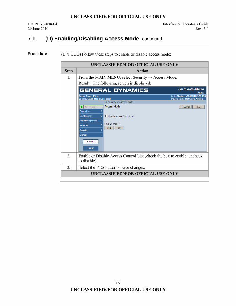
UNCLASSIFIED//FOR OFFICIAL USE ONLY HAIPE V3-098-04 Interface & Operator’s Guide 29 June 2010 Rev. 3.0
7-2
UNCLASSIFIED//FOR OFFICIAL USE ONLY
7.1 (U) Enabling/Disabling Access Mode, continued
Procedure (U//FOUO) Follow these steps to enable or disable access mode:
UNCLASSIFIED//FOR OFFICIAL USE ONLY Step Action
1. From the MAIN MENU, select Security → Access Mode. Result: The following screen is displayed:
2. Enable or Disable Access Control List (check the box to enable, uncheck to disable).
3. Select the YES button to save changes. UNCLASSIFIED//FOR OFFICIAL USE ONLY
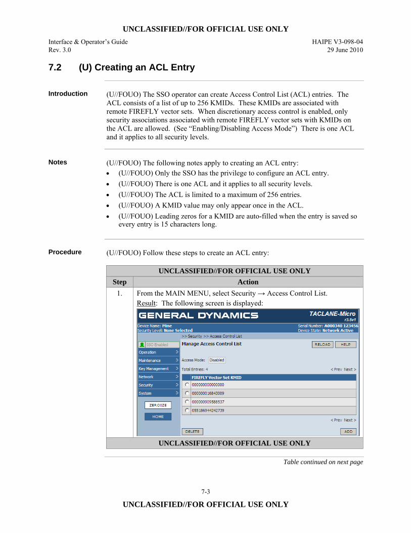
UNCLASSIFIED//FOR OFFICIAL USE ONLY Interface & Operator’s Guide HAIPE V3-098-04 Rev. 3.0 29 June 2010
7-3
UNCLASSIFIED//FOR OFFICIAL USE ONLY
7.2 (U) Creating an ACL Entry
Introduction (U//FOUO) The SSO operator can create Access Control List (ACL) entries. The
ACL consists of a list of up to 256 KMIDs. These KMIDs are associated with remote FIREFLY vector sets. When discretionary access control is enabled, only security associations associated with remote FIREFLY vector sets with KMIDs on the ACL are allowed. (See “Enabling/Disabling Access Mode”) There is one ACL and it applies to all security levels.
Notes (U//FOUO) The following notes apply to creating an ACL entry:
• (U//FOUO) Only the SSO has the privilege to configure an ACL entry. • (U//FOUO) There is one ACL and it applies to all security levels. • (U//FOUO) The ACL is limited to a maximum of 256 entries. • (U//FOUO) A KMID value may only appear once in the ACL. • (U//FOUO) Leading zeros for a KMID are auto-filled when the entry is saved so
every entry is 15 characters long.
Procedure (U//FOUO) Follow these steps to create an ACL entry:
UNCLASSIFIED//FOR OFFICIAL USE ONLY Step Action
1. From the MAIN MENU, select Security → Access Control List. Result: The following screen is displayed:
UNCLASSIFIED//FOR OFFICIAL USE ONLY
Table continued on next page
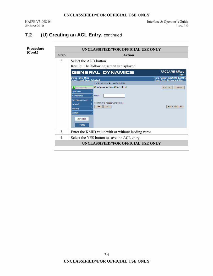
UNCLASSIFIED//FOR OFFICIAL USE ONLY HAIPE V3-098-04 Interface & Operator’s Guide 29 June 2010 Rev. 3.0
7-4
UNCLASSIFIED//FOR OFFICIAL USE ONLY
7.2 (U) Creating an ACL Entry, continued
Procedure (Cont.)
UNCLASSIFIED//FOR OFFICIAL USE ONLY Step Action
2. Select the ADD button. Result: The following screen is displayed:
3. Enter the KMID value with or without leading zeros. 4. Select the YES button to save the ACL entry.
UNCLASSIFIED//FOR OFFICIAL USE ONLY
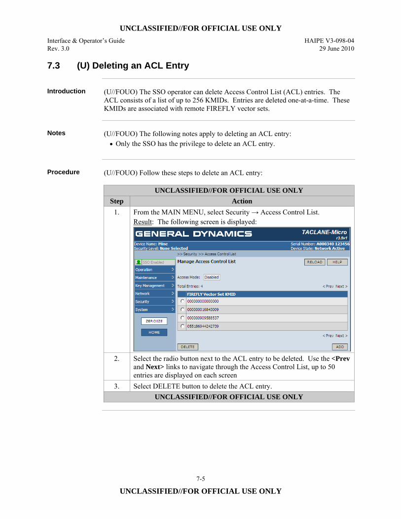
UNCLASSIFIED//FOR OFFICIAL USE ONLY Interface & Operator’s Guide HAIPE V3-098-04 Rev. 3.0 29 June 2010
7-5
UNCLASSIFIED//FOR OFFICIAL USE ONLY
7.3 (U) Deleting an ACL Entry
Introduction (U//FOUO) The SSO operator can delete Access Control List (ACL) entries. The
ACL consists of a list of up to 256 KMIDs. Entries are deleted one-at-a-time. These KMIDs are associated with remote FIREFLY vector sets.
Notes (U//FOUO) The following notes apply to deleting an ACL entry:
• Only the SSO has the privilege to delete an ACL entry.
Procedure (U//FOUO) Follow these steps to delete an ACL entry:
UNCLASSIFIED//FOR OFFICIAL USE ONLY Step Action
1. From the MAIN MENU, select Security → Access Control List. Result: The following screen is displayed:
2. Select the radio button next to the ACL entry to be deleted. Use the <Prev and Next> links to navigate through the Access Control List, up to 50 entries are displayed on each screen
3. Select DELETE button to delete the ACL entry. UNCLASSIFIED//FOR OFFICIAL USE ONLY
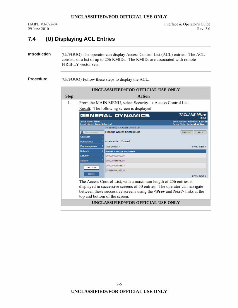
UNCLASSIFIED//FOR OFFICIAL USE ONLY HAIPE V3-098-04 Interface & Operator’s Guide 29 June 2010 Rev. 3.0
7-6
UNCLASSIFIED//FOR OFFICIAL USE ONLY
7.4 (U) Displaying ACL Entries
Introduction (U//FOUO) The operator can display Access Control List (ACL) entries. The ACL
consists of a list of up to 256 KMIDs. The KMIDs are associated with remote FIREFLY vector sets.
Procedure (U//FOUO) Follow these steps to display the ACL:
UNCLASSIFIED//FOR OFFICIAL USE ONLY Step Action
1. From the MAIN MENU, select Security → Access Control List. Result: The following screen is displayed:
The Access Control List, with a maximum length of 256 entries is displayed in successive screens of 50 entries. The operator can navigate between these successive screens using the <Prev and Next> links at the top and bottom of the screen.
UNCLASSIFIED//FOR OFFICIAL USE ONLY
UNCLASSIFIED//FOR OFFICIAL USE ONLY Interface & Operator’s Guide HAIPE V3-098-04 Rev. 3.0 29 June 2010
7-7
UNCLASSIFIED//FOR OFFICIAL USE ONLY
7.5 (U) Adding a Network Manager
Introduction (U//FOUO) The SSO can configure the TACLANE to be managed by a remote
Network Manager. The TACLANE can support up to twelve (12) Network Managers. For each manager, the SSO configures the following parameters: • Manager name • Passwords or Master Keys for Authentication and Confidentiality
(U//FOUO) For each Manager, the SSO may configure the following notification (traps) parameters: • Enable/Disable (defaults to Disable) • IP version and IP address of the Manager • Port number (defaulted to 162).
CT vs. PT Side Management
(U//FOUO) A TACLANE can be managed from either its Plain Text (PT) or Cipher Text (CT) interface. CT-side management traffic is encrypted from the remote manager to the managed TACLANE using the privacy encryption of the SNMP User Security Model, and by the TACLANEs between the TACLANE fronting the Manager and the managed TACLANE. PT-side management traffic is encrypted using the privacy encryption of the SNMP User Security Model, and is used to manage the TACLANE fronting the Manager.
Network Managers
(U//FOUO) The following notes apply to the Network Managers: • (U//FOUO) The TACLANE supports up to 12 Network Managers in addition to
the local operator and the SSO. • (U//FOUO) The Manager Name can be between 1 and 32 characters in length
consisting of letters and numbers. Space characters and symbols are not accepted
• (U//FOUO) The TACLANE does not have default Network Managers. • (U//FOUO) The SSO must configure at least 1 Network Manager from the HMI
to enable remote management. The same Network Manager Name and Passwords or Master Keys must be defined at a Network Manager Workstation before the TACLANE can be managed by that Workstation.
– (U//FOUO) Passwords must be between 12 and 32 characters, and must contain at least one each of the following: uppercase letter, lowercase letter, number, and special character.
– (U//FOUO) Master Keys must be entered as 40 hexadecimal character (i.e., characters from the set {0… 9, A, B, C, D, E, F}) strings.
Continued on next page

UNCLASSIFIED//FOR OFFICIAL USE ONLY HAIPE V3-098-04 Interface & Operator’s Guide 29 June 2010 Rev. 3.0
7-8
UNCLASSIFIED//FOR OFFICIAL USE ONLY
7.5 (U) Adding a Network Manager, continued
Secure Remote Management Using SNMP
(U//FOUO) TACLANEs can be managed by an SNMPv3 Network Manager using the IETF-Standard, and HAIPE and General Dynamics C4 Systems Enterprise MIBs identified in Section 2.3 and the MIB Objects defined in Appendix E of this manual. (U//FOUO) The GEM X Network Manager from General Dynamics provides full management of TACLANEs using Simple Network Management Protocol (SNMPv3). (U//FOUO) The GEM X Network Manager from General Dynamics can also provide network management of TACLANE-protected network elements using SNMPv3. Please refer to the appropriate GEM X Operator’s Manual for more information on configuring the TACLANE fronting the GEM X and for more information on GEM X.
Notes (U//FOUO) The following notes apply to a local HMI operator configuring the
network manager parameters: • (U//FOUO) Only the SSO can configure the first Network Manager for a
TACLANE • (U//FOUO) Subsequent Network Managers can be configured by either the SSO
or a presently configured Network Manager. • (U//FOUO) The TACLANE supports up to 12 Network Managers in addition to
the local operator and the SSO. • (U//FOUO) If the TACLANE is remotely managed by a GEM X and the UDP
port is changed to a value other than the standard 161/162 port configuration, the GEM X will not receive traps from the TACLANE.
Continued on next page

UNCLASSIFIED//FOR OFFICIAL USE ONLY Interface & Operator’s Guide HAIPE V3-098-04 Rev. 3.0 29 June 2010
7-9
UNCLASSIFIED//FOR OFFICIAL USE ONLY
7.5 (U) Adding a Network Manager, continued
Procedure (U//FOUO) Follow these steps to add a network manager:
UNCLASSIFIED//FOR OFFICIAL USE ONLY Step Action
1. From the MAIN MENU, select System → Network Managers. Result: The following screen is displayed:
UNCLASSIFIED//FOR OFFICIAL USE ONLY
Table continued on next page
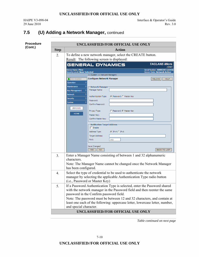
UNCLASSIFIED//FOR OFFICIAL USE ONLY HAIPE V3-098-04 Interface & Operator’s Guide 29 June 2010 Rev. 3.0
7-10
UNCLASSIFIED//FOR OFFICIAL USE ONLY
7.5 (U) Adding a Network Manager, continued
Procedure (Cont.)
UNCLASSIFIED//FOR OFFICIAL USE ONLY Step Action
2. To define a new network manager, select the CREATE button. Result: The following screen is displayed:
3. Enter a Manager Name consisting of between 1 and 32 alphanumeric characters. Note: The Manager Name cannot be changed once the Network Manager has been configured.
4. Select the type of credential to be used to authenticate the network manager by selecting the applicable Authentication Type radio button (i.e., Password or Master Key)
5. If a Password Authentication Type is selected, enter the Password shared with the network manager in the Password field and then reenter the same password in the Confirm password field. Note: The password must be between 12 and 32 characters, and contain at least one each of the following: uppercase letter, lowercase letter, number, and special character.
UNCLASSIFIED//FOR OFFICIAL USE ONLY
Table continued on next page
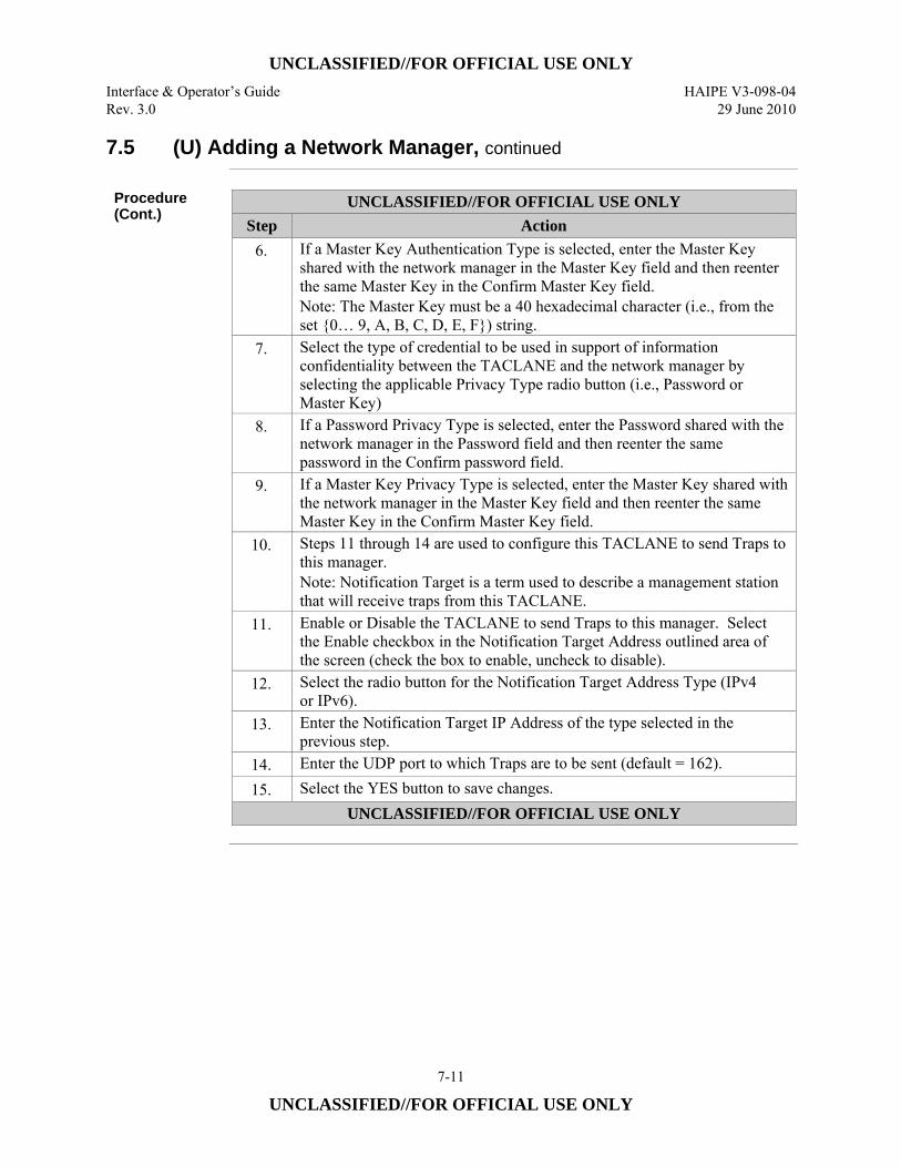
UNCLASSIFIED//FOR OFFICIAL USE ONLY Interface & Operator’s Guide HAIPE V3-098-04 Rev. 3.0 29 June 2010
7-11
UNCLASSIFIED//FOR OFFICIAL USE ONLY
7.5 (U) Adding a Network Manager, continued
Procedure (Cont.)
UNCLASSIFIED//FOR OFFICIAL USE ONLY Step Action
6. If a Master Key Authentication Type is selected, enter the Master Key shared with the network manager in the Master Key field and then reenter the same Master Key in the Confirm Master Key field. Note: The Master Key must be a 40 hexadecimal character (i.e., from the set {0… 9, A, B, C, D, E, F}) string.
7. Select the type of credential to be used in support of information confidentiality between the TACLANE and the network manager by selecting the applicable Privacy Type radio button (i.e., Password or Master Key)
8. If a Password Privacy Type is selected, enter the Password shared with the network manager in the Password field and then reenter the same password in the Confirm password field.
9. If a Master Key Privacy Type is selected, enter the Master Key shared with the network manager in the Master Key field and then reenter the same Master Key in the Confirm Master Key field.
10. Steps 11 through 14 are used to configure this TACLANE to send Traps to this manager. Note: Notification Target is a term used to describe a management station that will receive traps from this TACLANE.
11. Enable or Disable the TACLANE to send Traps to this manager. Select the Enable checkbox in the Notification Target Address outlined area of the screen (check the box to enable, uncheck to disable).
12. Select the radio button for the Notification Target Address Type (IPv4 or IPv6).
13. Enter the Notification Target IP Address of the type selected in the previous step.
14. Enter the UDP port to which Traps are to be sent (default = 162). 15. Select the YES button to save changes.
UNCLASSIFIED//FOR OFFICIAL USE ONLY
UNCLASSIFIED//FOR OFFICIAL USE ONLY HAIPE V3-098-04 Interface & Operator’s Guide 29 June 2010 Rev. 3.0
7-12
UNCLASSIFIED//FOR OFFICIAL USE ONLY
7.6 (U) Editing a Network Manager’s Configuration
Introduction (U//FOUO). For each previously configured Network Manager, the SSO operator
can modify the following parameters: • Authentication Password or Master Key • Privacy Password or Master Key
(U//FOUO) For each Manager, the SSO can modify the following notification (traps) parameters: • Enable/Disable notifications (TRAPS) (defaulted to Enable) • IP version and IP address to which TRAPS are to be sent • Port number to which TRAPS are to be sent (defaulted to 162).
Notes (U//FOUO) The following notes apply to an SSO editing the Remote Manager
configuration parameters in the TACLANE: • (U//FOUO) A Remote Manager Name cannot be changed once created. To
change the name, delete that existing Manager and create a new Remote Manager configuration.
• (U//FOUO) The default value for the UDP Port to which Traps are sent is 162. • (U//FOUO) If the TACLANE is remotely managed by a GEM X and the UDP
port is changed to a value other than the standard 161/162 port configuration, the GEM X will not receive traps from the TACLANE.
Continued on next page
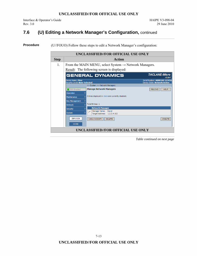
UNCLASSIFIED//FOR OFFICIAL USE ONLY Interface & Operator’s Guide HAIPE V3-098-04 Rev. 3.0 29 June 2010
7-13
UNCLASSIFIED//FOR OFFICIAL USE ONLY
7.6 (U) Editing a Network Manager’s Configuration, continued
Procedure (U//FOUO) Follow these steps to edit a Network Manager’s configuration:
UNCLASSIFIED//FOR OFFICIAL USE ONLY Step Action
1. From the MAIN MENU, select System → Network Managers. Result: The following screen is displayed:
UNCLASSIFIED//FOR OFFICIAL USE ONLY
Table continued on next page
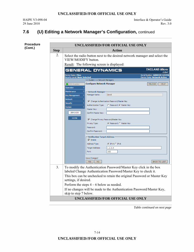
UNCLASSIFIED//FOR OFFICIAL USE ONLY HAIPE V3-098-04 Interface & Operator’s Guide 29 June 2010 Rev. 3.0
7-14
UNCLASSIFIED//FOR OFFICIAL USE ONLY
7.6 (U) Editing a Network Manager’s Configuration, continued
Procedure (Cont.)
UNCLASSIFIED//FOR OFFICIAL USE ONLY Step Action
2. Select the radio button next to the desired network manager and select the VIEW/MODIFY button. Result: The following screen is displayed:
3. To modify the Authentication Password/Master Key click in the box labeled Change Authentication Password/Master Key to check it. This box can be unchecked to retain the original Password or Master Key settings, if desired. Perform the steps 4 – 6 below as needed. If no changes will be made to the Authentication Password/Master Key, skip to step 7 below.
UNCLASSIFIED//FOR OFFICIAL USE ONLY
Table continued on next page
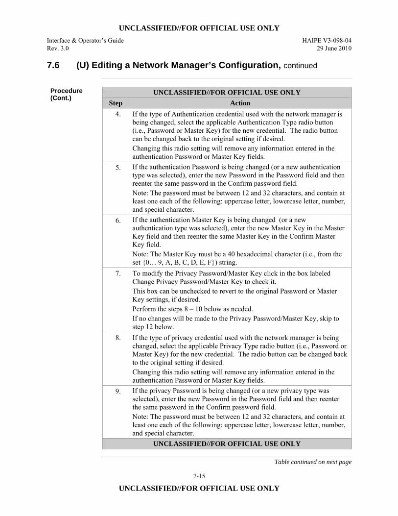
UNCLASSIFIED//FOR OFFICIAL USE ONLY Interface & Operator’s Guide HAIPE V3-098-04 Rev. 3.0 29 June 2010
7-15
UNCLASSIFIED//FOR OFFICIAL USE ONLY
7.6 (U) Editing a Network Manager’s Configuration, continued
Procedure (Cont.)
UNCLASSIFIED//FOR OFFICIAL USE ONLY Step Action
4. If the type of Authentication credential used with the network manager is being changed, select the applicable Authentication Type radio button (i.e., Password or Master Key) for the new credential. The radio button can be changed back to the original setting if desired. Changing this radio setting will remove any information entered in the authentication Password or Master Key fields.
5. If the authentication Password is being changed (or a new authentication type was selected), enter the new Password in the Password field and then reenter the same password in the Confirm password field. Note: The password must be between 12 and 32 characters, and contain at least one each of the following: uppercase letter, lowercase letter, number, and special character.
6. If the authentication Master Key is being changed (or a new authentication type was selected), enter the new Master Key in the Master Key field and then reenter the same Master Key in the Confirm Master Key field. Note: The Master Key must be a 40 hexadecimal character (i.e., from the set {0… 9, A, B, C, D, E, F}) string.
7. To modify the Privacy Password/Master Key click in the box labeled Change Privacy Password/Master Key to check it. This box can be unchecked to revert to the original Password or Master Key settings, if desired. Perform the steps 8 – 10 below as needed. If no changes will be made to the Privacy Password/Master Key, skip to step 12 below.
8. If the type of privacy credential used with the network manager is being changed, select the applicable Privacy Type radio button (i.e., Password or Master Key) for the new credential. The radio button can be changed back to the original setting if desired. Changing this radio setting will remove any information entered in the authentication Password or Master Key fields.
9. If the privacy Password is being changed (or a new privacy type was selected), enter the new Password in the Password field and then reenter the same password in the Confirm password field. Note: The password must be between 12 and 32 characters, and contain at least one each of the following: uppercase letter, lowercase letter, number, and special character.
UNCLASSIFIED//FOR OFFICIAL USE ONLY
Table continued on next page
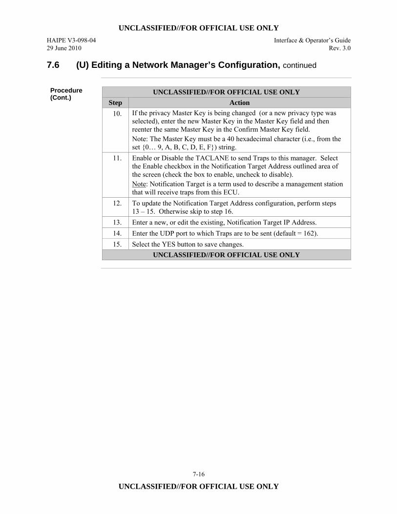
UNCLASSIFIED//FOR OFFICIAL USE ONLY HAIPE V3-098-04 Interface & Operator’s Guide 29 June 2010 Rev. 3.0
7-16
UNCLASSIFIED//FOR OFFICIAL USE ONLY
7.6 (U) Editing a Network Manager’s Configuration, continued
Procedure (Cont.)
UNCLASSIFIED//FOR OFFICIAL USE ONLY Step Action
10. If the privacy Master Key is being changed (or a new privacy type was selected), enter the new Master Key in the Master Key field and then reenter the same Master Key in the Confirm Master Key field. Note: The Master Key must be a 40 hexadecimal character (i.e., from the set {0… 9, A, B, C, D, E, F}) string.
11. Enable or Disable the TACLANE to send Traps to this manager. Select the Enable checkbox in the Notification Target Address outlined area of the screen (check the box to enable, uncheck to disable). Note: Notification Target is a term used to describe a management station that will receive traps from this ECU.
12. To update the Notification Target Address configuration, perform steps 13 – 15. Otherwise skip to step 16.
13. Enter a new, or edit the existing, Notification Target IP Address. 14. Enter the UDP port to which Traps are to be sent (default = 162). 15. Select the YES button to save changes.
UNCLASSIFIED//FOR OFFICIAL USE ONLY
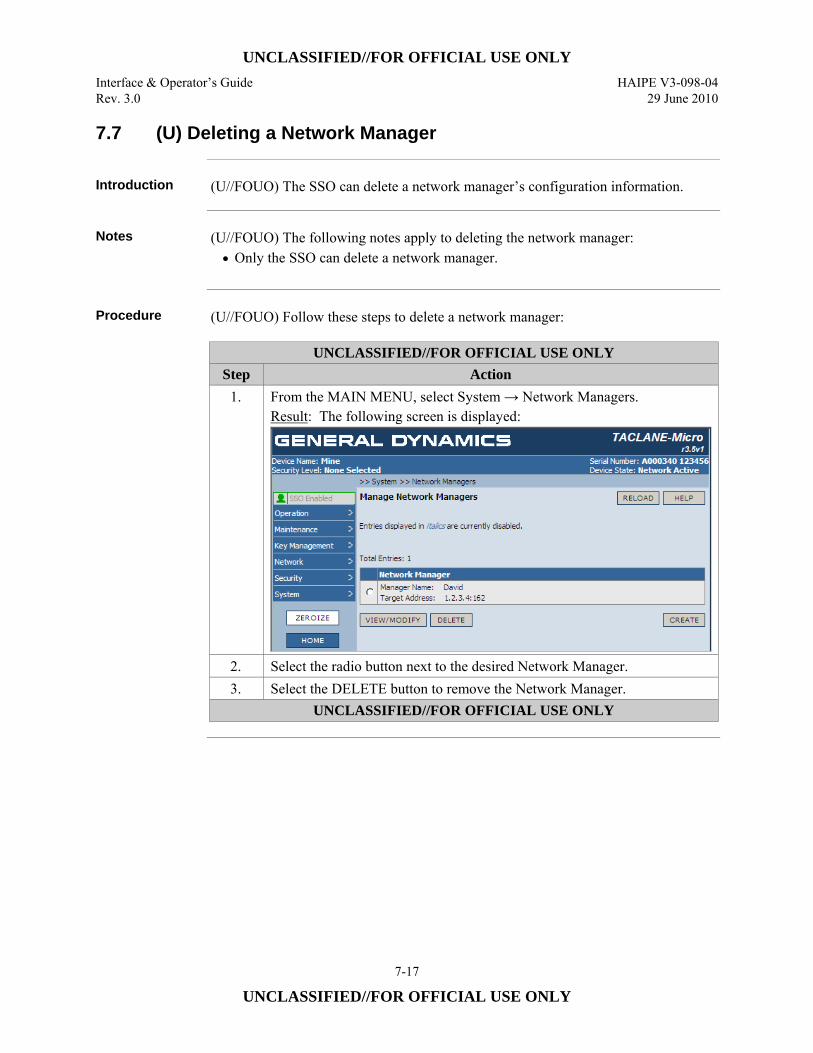
UNCLASSIFIED//FOR OFFICIAL USE ONLY Interface & Operator’s Guide HAIPE V3-098-04 Rev. 3.0 29 June 2010
7-17
UNCLASSIFIED//FOR OFFICIAL USE ONLY
7.7 (U) Deleting a Network Manager
Introduction (U//FOUO) The SSO can delete a network manager’s configuration information.
Notes (U//FOUO) The following notes apply to deleting the network manager:
• Only the SSO can delete a network manager.
Procedure (U//FOUO) Follow these steps to delete a network manager:
UNCLASSIFIED//FOR OFFICIAL USE ONLY Step Action
1. From the MAIN MENU, select System → Network Managers. Result: The following screen is displayed:
2. Select the radio button next to the desired Network Manager. 3. Select the DELETE button to remove the Network Manager.
UNCLASSIFIED//FOR OFFICIAL USE ONLY
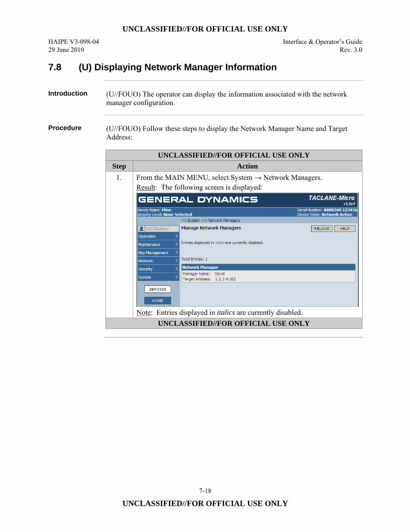
UNCLASSIFIED//FOR OFFICIAL USE ONLY HAIPE V3-098-04 Interface & Operator’s Guide 29 June 2010 Rev. 3.0
7-18
UNCLASSIFIED//FOR OFFICIAL USE ONLY
7.8 (U) Displaying Network Manager Information
Introduction (U//FOUO) The operator can display the information associated with the network
manager configuration.
Procedure (U//FOUO) Follow these steps to display the Network Manager Name and Target
Address:
UNCLASSIFIED//FOR OFFICIAL USE ONLY Step Action
1. From the MAIN MENU, select System → Network Managers. Result: The following screen is displayed:
Note: Entries displayed in italics are currently disabled.
UNCLASSIFIED//FOR OFFICIAL USE ONLY
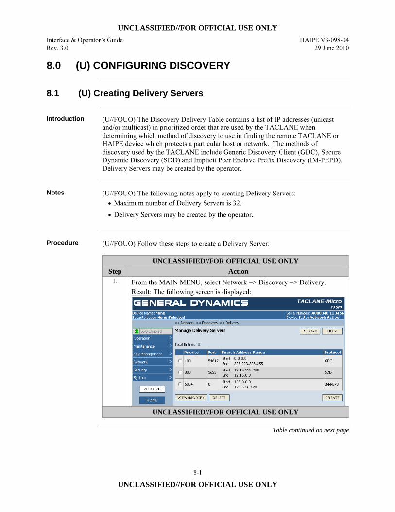
UNCLASSIFIED//FOR OFFICIAL USE ONLY Interface & Operator’s Guide HAIPE V3-098-04 Rev. 3.0 29 June 2010
8-1
UNCLASSIFIED//FOR OFFICIAL USE ONLY
8.0 (U) CONFIGURING DISCOVERY
8.1 (U) Creating Delivery Servers
Introduction (U//FOUO) The Discovery Delivery Table contains a list of IP addresses (unicast
and/or multicast) in prioritized order that are used by the TACLANE when determining which method of discovery to use in finding the remote TACLANE or HAIPE device which protects a particular host or network. The methods of discovery used by the TACLANE include Generic Discovery Client (GDC), Secure Dynamic Discovery (SDD) and Implicit Peer Enclave Prefix Discovery (IM-PEPD). Delivery Servers may be created by the operator.
Notes (U//FOUO) The following notes apply to creating Delivery Servers:
• Maximum number of Delivery Servers is 32. • Delivery Servers may be created by the operator.
Procedure (U//FOUO) Follow these steps to create a Delivery Server:
UNCLASSIFIED//FOR OFFICIAL USE ONLY Step Action
1. From the MAIN MENU, select Network => Discovery => Delivery. Result: The following screen is displayed:
UNCLASSIFIED//FOR OFFICIAL USE ONLY
Table continued on next page
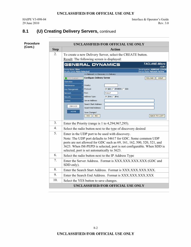
UNCLASSIFIED//FOR OFFICIAL USE ONLY HAIPE V3-098-04 Interface & Operator’s Guide 29 June 2010 Rev. 3.0
8-2
UNCLASSIFIED//FOR OFFICIAL USE ONLY
8.1 (U) Creating Delivery Servers, continued
Procedure (Cont.)
UNCLASSIFIED//FOR OFFICIAL USE ONLY Step Action
2. To create a new Delivery Server, select the CREATE button. Result: The following screen is displayed:
3. Enter the Priority (range is 1 to 4,294,967,295). 4. Select the radio button next to the type of discovery desired 5. Enter in the UDP port to be used with discovery.
Note: The UDP port defaults to 54617 for GDC. Some common UDP ports are not allowed for GDC such as 69, 161, 162, 500, 520, 521, and 3623. When IM-PEPD is selected, port is not configurable. When SDD is selected, port is set automatically to 3623.
6. Select the radio button next to the IP Address Type 7. Enter the Server Address. Format is XXX.XXX.XXX.XXX (GDC and
SDD only). 8. Enter the Search Start Address. Format is XXX.XXX.XXX.XXX. 9. Enter the Search End Address. Format is XXX.XXX.XXX.XXX
10. Select the YES button to save changes. UNCLASSIFIED//FOR OFFICIAL USE ONLY
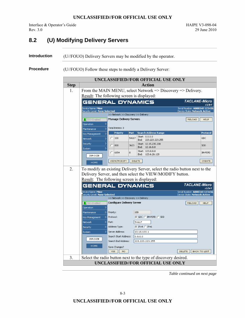
UNCLASSIFIED//FOR OFFICIAL USE ONLY Interface & Operator’s Guide HAIPE V3-098-04 Rev. 3.0 29 June 2010
8-3
UNCLASSIFIED//FOR OFFICIAL USE ONLY
8.2 (U) Modifying Delivery Servers
Introduction (U//FOUO) Delivery Servers may be modified by the operator.
Procedure (U//FOUO) Follow these steps to modify a Delivery Server:
UNCLASSIFIED//FOR OFFICIAL USE ONLY Step Action
1. From the MAIN MENU, select Network => Discovery => Delivery. Result: The following screen is displayed:
2. To modify an existing Delivery Server, select the radio button next to the Delivery Server, and then select the VIEW/MODIFY button. Result: The following screen is displayed:
3. Select the radio button next to the type of discovery desired. UNCLASSIFIED//FOR OFFICIAL USE ONLY
Table continued on next page
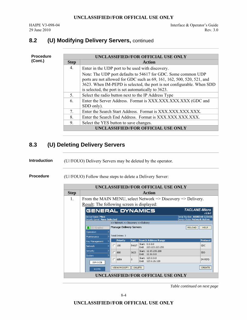
UNCLASSIFIED//FOR OFFICIAL USE ONLY HAIPE V3-098-04 Interface & Operator’s Guide 29 June 2010 Rev. 3.0
8-4
UNCLASSIFIED//FOR OFFICIAL USE ONLY
8.2 (U) Modifying Delivery Servers, continued
Procedure (Cont.)
UNCLASSIFIED//FOR OFFICIAL USE ONLY Step Action
4. Enter in the UDP port to be used with discovery. Note: The UDP port defaults to 54617 for GDC. Some common UDP ports are not allowed for GDC such as 69, 161, 162, 500, 520, 521, and 3623. When IM-PEPD is selected, the port is not configurable. When SDD is selected, the port is set automatically to 3623.
5. Select the radio button next to the IP Address Type 6. Enter the Server Address. Format is XXX.XXX.XXX.XXX (GDC and
SDD only). 7. Enter the Search Start Address. Format is XXX.XXX.XXX.XXX. 8. Enter the Search End Address. Format is XXX.XXX.XXX.XXX. 9. Select the YES button to save changes.
UNCLASSIFIED//FOR OFFICIAL USE ONLY
8.3 (U) Deleting Delivery Servers
Introduction (U//FOUO) Delivery Servers may be deleted by the operator.
Procedure (U//FOUO) Follow these steps to delete a Delivery Server:
UNCLASSIFIED//FOR OFFICIAL USE ONLY Step Action
1. From the MAIN MENU, select Network => Discovery => Delivery. Result: The following screen is displayed:
UNCLASSIFIED//FOR OFFICIAL USE ONLY
Table continued on next page
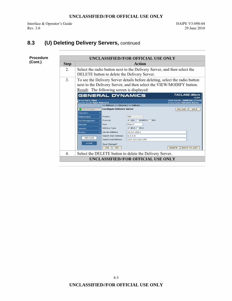
UNCLASSIFIED//FOR OFFICIAL USE ONLY Interface & Operator’s Guide HAIPE V3-098-04 Rev. 3.0 29 June 2010
8-5
UNCLASSIFIED//FOR OFFICIAL USE ONLY
8.3 (U) Deleting Delivery Servers, continued
Procedure (Cont.)
UNCLASSIFIED//FOR OFFICIAL USE ONLY Step Action
2. Select the radio button next to the Delivery Server, and then select the DELETE button to delete the Delivery Server.
3. To see the Delivery Server details before deleting, select the radio button next to the Delivery Server, and then select the VIEW/MODIFY button. Result: The following screen is displayed:
4. Select the DELETE button to delete the Delivery Server. UNCLASSIFIED//FOR OFFICIAL USE ONLY
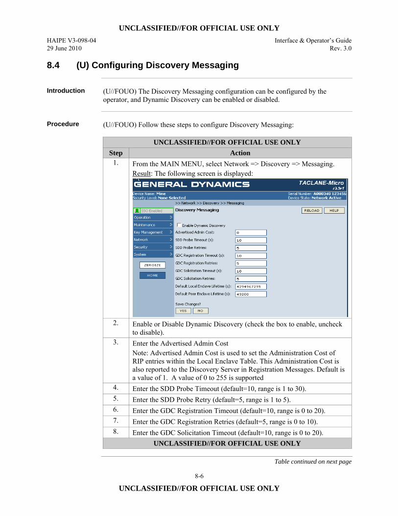
UNCLASSIFIED//FOR OFFICIAL USE ONLY HAIPE V3-098-04 Interface & Operator’s Guide 29 June 2010 Rev. 3.0
8-6
UNCLASSIFIED//FOR OFFICIAL USE ONLY
8.4 (U) Configuring Discovery Messaging
Introduction (U//FOUO) The Discovery Messaging configuration can be configured by the
operator, and Dynamic Discovery can be enabled or disabled.
Procedure (U//FOUO) Follow these steps to configure Discovery Messaging:
UNCLASSIFIED//FOR OFFICIAL USE ONLY Step Action
1. From the MAIN MENU, select Network => Discovery => Messaging. Result: The following screen is displayed:
2. Enable or Disable Dynamic Discovery (check the box to enable, uncheck to disable).
3. Enter the Advertised Admin Cost Note: Advertised Admin Cost is used to set the Administration Cost of RIP entries within the Local Enclave Table. This Administration Cost is also reported to the Discovery Server in Registration Messages. Default is a value of 1. A value of 0 to 255 is supported
4. Enter the SDD Probe Timeout (default=10, range is 1 to 30). 5. Enter the SDD Probe Retry (default=5, range is 1 to 5). 6. Enter the GDC Registration Timeout (default=10, range is 0 to 20). 7. Enter the GDC Registration Retries (default=5, range is 0 to 10). 8. Enter the GDC Solicitation Timeout (default=10, range is 0 to 20).
UNCLASSIFIED//FOR OFFICIAL USE ONLY
Table continued on next page
UNCLASSIFIED//FOR OFFICIAL USE ONLY Interface & Operator’s Guide HAIPE V3-098-04 Rev. 3.0 29 June 2010
8-7
UNCLASSIFIED//FOR OFFICIAL USE ONLY
8.4 (U) Configuring Discovery Messaging, continued
Procedure (Cont.)
UNCLASSIFIED//FOR OFFICIAL USE ONLY Step Action
9. Enter the GDC Solicitation Retries (default=5, range is 0 to 10). 10. Enter the Default Local Enclave Lifetime (default=4,294,967,295, range
is 0 to 4,294,967,295). Note: This is the default lifetime setting for entries placed in the Local Enclave Table, when none is specified. This applies to RIP learned entries.
11. Enter the Default Peer Enclave Lifetime (default=43,200, range is 60 to 4,294,967,295). Note: It is necessary to configure the Default Peer Enclave Lifetime to accommodate the network in which the TACLANE is operating. In networks using IM-PEPD or if NAT devices may be encountered, set the Default Peer Enclave Lifetime to the maximum value so Peer Enclave Table entries do not time out prematurely.
12. Select the YES button to save changes. UNCLASSIFIED//FOR OFFICIAL USE ONLY
8.5 (U) Creating Registration Servers
Introduction (U//FOUO) The Discovery Registration Server table contains a list of Generic
Discovery Servers to which the TACLANE will send Registration Messages, informing the servers within the list which host or networks the TACLANE protects on the PT interface. The TACLANE uses information in the Local Enclave Prefix table to inform the Generic Discovery Server about which PT networks or hosts it protects.
Notes (U//FOUO) The following notes apply to configuring Solicitation Reception
Addresses: • Maximum number of Registration Server Addresses is 8.
Continued on next page
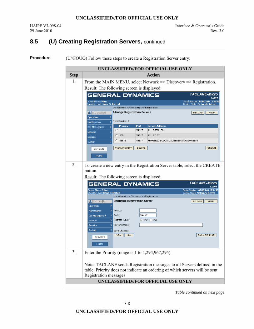
UNCLASSIFIED//FOR OFFICIAL USE ONLY HAIPE V3-098-04 Interface & Operator’s Guide 29 June 2010 Rev. 3.0
8-8
UNCLASSIFIED//FOR OFFICIAL USE ONLY
8.5 (U) Creating Registration Servers, continued
Procedure (U//FOUO) Follow these steps to create a Registration Server entry:
UNCLASSIFIED//FOR OFFICIAL USE ONLY Step Action
1. From the MAIN MENU, select Network => Discovery => Registration. Result: The following screen is displayed:
2. To create a new entry in the Registration Server table, select the CREATE button. Result: The following screen is displayed:
3. Enter the Priority (range is 1 to 4,294,967,295). Note: TACLANE sends Registration messages to all Servers defined in the table. Priority does not indicate an ordering of which servers will be sent Registration messages
UNCLASSIFIED//FOR OFFICIAL USE ONLY
Table continued on next page
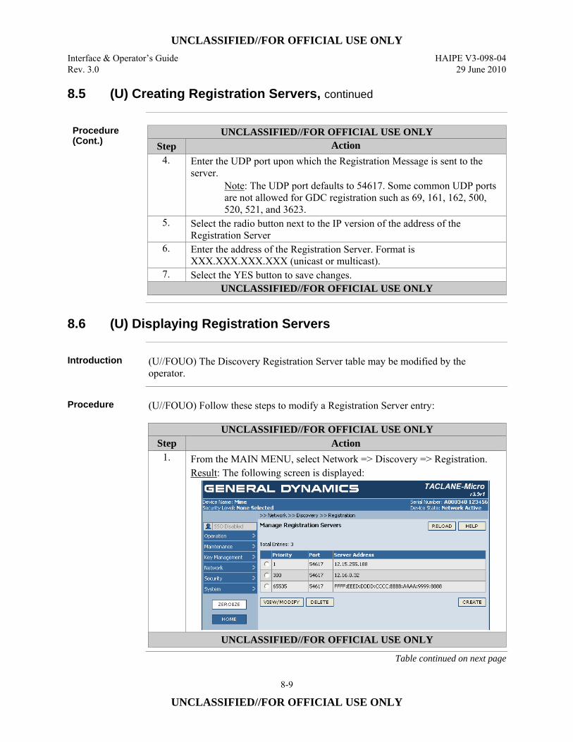
UNCLASSIFIED//FOR OFFICIAL USE ONLY Interface & Operator’s Guide HAIPE V3-098-04 Rev. 3.0 29 June 2010
8-9
UNCLASSIFIED//FOR OFFICIAL USE ONLY
8.5 (U) Creating Registration Servers, continued
Procedure (Cont.)
UNCLASSIFIED//FOR OFFICIAL USE ONLY Step Action
4. Enter the UDP port upon which the Registration Message is sent to the server.
Note: The UDP port defaults to 54617. Some common UDP ports are not allowed for GDC registration such as 69, 161, 162, 500, 520, 521, and 3623.
5. Select the radio button next to the IP version of the address of the Registration Server
6. Enter the address of the Registration Server. Format is XXX.XXX.XXX.XXX (unicast or multicast).
7. Select the YES button to save changes. UNCLASSIFIED//FOR OFFICIAL USE ONLY
8.6 (U) Displaying Registration Servers
Introduction (U//FOUO) The Discovery Registration Server table may be modified by the
operator.
Procedure (U//FOUO) Follow these steps to modify a Registration Server entry:
UNCLASSIFIED//FOR OFFICIAL USE ONLY Step Action
1. From the MAIN MENU, select Network => Discovery => Registration. Result: The following screen is displayed:
UNCLASSIFIED//FOR OFFICIAL USE ONLY
Table continued on next page
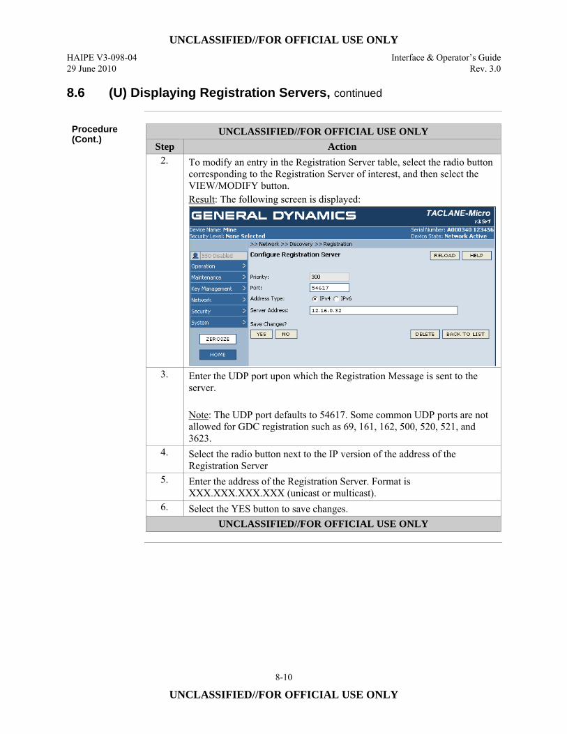
UNCLASSIFIED//FOR OFFICIAL USE ONLY HAIPE V3-098-04 Interface & Operator’s Guide 29 June 2010 Rev. 3.0
8-10
UNCLASSIFIED//FOR OFFICIAL USE ONLY
8.6 (U) Displaying Registration Servers, continued
Procedure (Cont.)
UNCLASSIFIED//FOR OFFICIAL USE ONLY Step Action
2. To modify an entry in the Registration Server table, select the radio button corresponding to the Registration Server of interest, and then select the VIEW/MODIFY button. Result: The following screen is displayed:
3. Enter the UDP port upon which the Registration Message is sent to the server. Note: The UDP port defaults to 54617. Some common UDP ports are not allowed for GDC registration such as 69, 161, 162, 500, 520, 521, and 3623.
4. Select the radio button next to the IP version of the address of the Registration Server
5. Enter the address of the Registration Server. Format is XXX.XXX.XXX.XXX (unicast or multicast).
6. Select the YES button to save changes. UNCLASSIFIED//FOR OFFICIAL USE ONLY
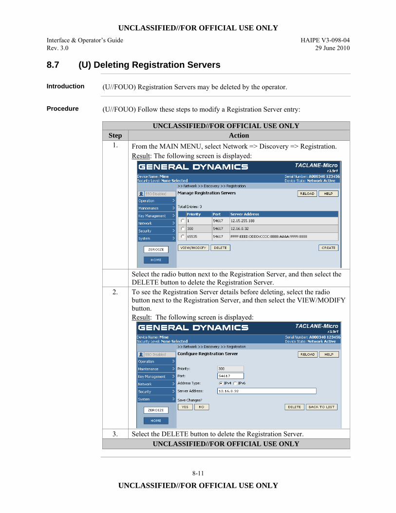
UNCLASSIFIED//FOR OFFICIAL USE ONLY Interface & Operator’s Guide HAIPE V3-098-04 Rev. 3.0 29 June 2010
8-11
UNCLASSIFIED//FOR OFFICIAL USE ONLY
8.7 (U) Deleting Registration Servers
Introduction (U//FOUO) Registration Servers may be deleted by the operator.
Procedure (U//FOUO) Follow these steps to modify a Registration Server entry:
UNCLASSIFIED//FOR OFFICIAL USE ONLY Step Action
1. From the MAIN MENU, select Network => Discovery => Registration. Result: The following screen is displayed:
Select the radio button next to the Registration Server, and then select the DELETE button to delete the Registration Server.
2. To see the Registration Server details before deleting, select the radio button next to the Registration Server, and then select the VIEW/MODIFY button. Result: The following screen is displayed:
3. Select the DELETE button to delete the Registration Server. UNCLASSIFIED//FOR OFFICIAL USE ONLY
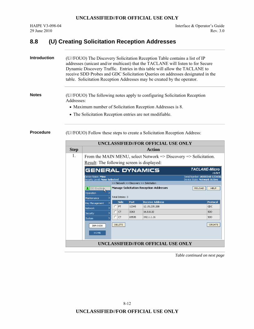
UNCLASSIFIED//FOR OFFICIAL USE ONLY HAIPE V3-098-04 Interface & Operator’s Guide 29 June 2010 Rev. 3.0
8-12
UNCLASSIFIED//FOR OFFICIAL USE ONLY
8.8 (U) Creating Solicitation Reception Addresses
Introduction (U//FOUO) The Discovery Solicitation Reception Table contains a list of IP
addresses (unicast and/or multicast) that the TACLANE will listen to for Secure Dynamic Discovery Traffic. Entries in this table will allow the TACLANE to receive SDD Probes and GDC Solicitation Queries on addresses designated in the table. Solicitation Reception Addresses may be created by the operator.
Notes (U//FOUO) The following notes apply to configuring Solicitation Reception
Addresses: • Maximum number of Solicitation Reception Addresses is 8. • The Solicitation Reception entries are not modifiable.
Procedure (U//FOUO) Follow these steps to create a Solicitation Reception Address:
UNCLASSIFIED//FOR OFFICIAL USE ONLY Step Action
1. From the MAIN MENU, select Network => Discovery => Solicitation. Result: The following screen is displayed:
UNCLASSIFIED//FOR OFFICIAL USE ONLY
Table continued on next page
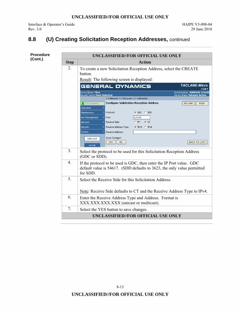
UNCLASSIFIED//FOR OFFICIAL USE ONLY Interface & Operator’s Guide HAIPE V3-098-04 Rev. 3.0 29 June 2010
8-13
UNCLASSIFIED//FOR OFFICIAL USE ONLY
8.8 (U) Creating Solicitation Reception Addresses, continued
Procedure (Cont.)
UNCLASSIFIED//FOR OFFICIAL USE ONLY Step Action
2. To create a new Solicitation Reception Address, select the CREATE button. Result: The following screen is displayed:
3. Select the protocol to be used for this Solicitation Reception Address (GDC or SDD).
4. If the protocol to be used is GDC, then enter the IP Port value. GDC default value is 54617. (SDD defaults to 3623, the only value permitted for SDD.
5. Select the Receive Side for this Solicitation Address. Note: Receive Side defaults to CT and the Receive Address Type to IPv4.
6. Enter the Receive Address Type and Address. Format is XXX.XXX.XXX.XXX (unicast or multicast).
7. Select the YES button to save changes. UNCLASSIFIED//FOR OFFICIAL USE ONLY
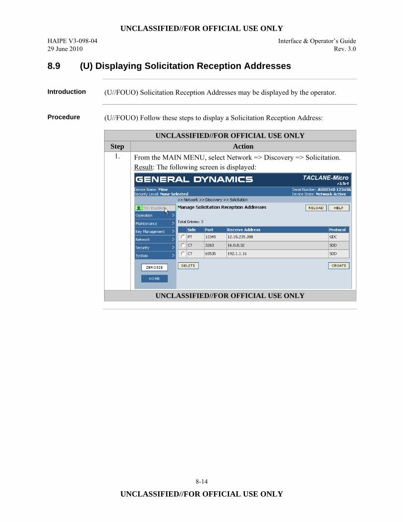
UNCLASSIFIED//FOR OFFICIAL USE ONLY HAIPE V3-098-04 Interface & Operator’s Guide 29 June 2010 Rev. 3.0
8-14
UNCLASSIFIED//FOR OFFICIAL USE ONLY
8.9 (U) Displaying Solicitation Reception Addresses
Introduction (U//FOUO) Solicitation Reception Addresses may be displayed by the operator.
Procedure (U//FOUO) Follow these steps to display a Solicitation Reception Address:
UNCLASSIFIED//FOR OFFICIAL USE ONLY Step Action
1. From the MAIN MENU, select Network => Discovery => Solicitation. Result: The following screen is displayed:
UNCLASSIFIED//FOR OFFICIAL USE ONLY
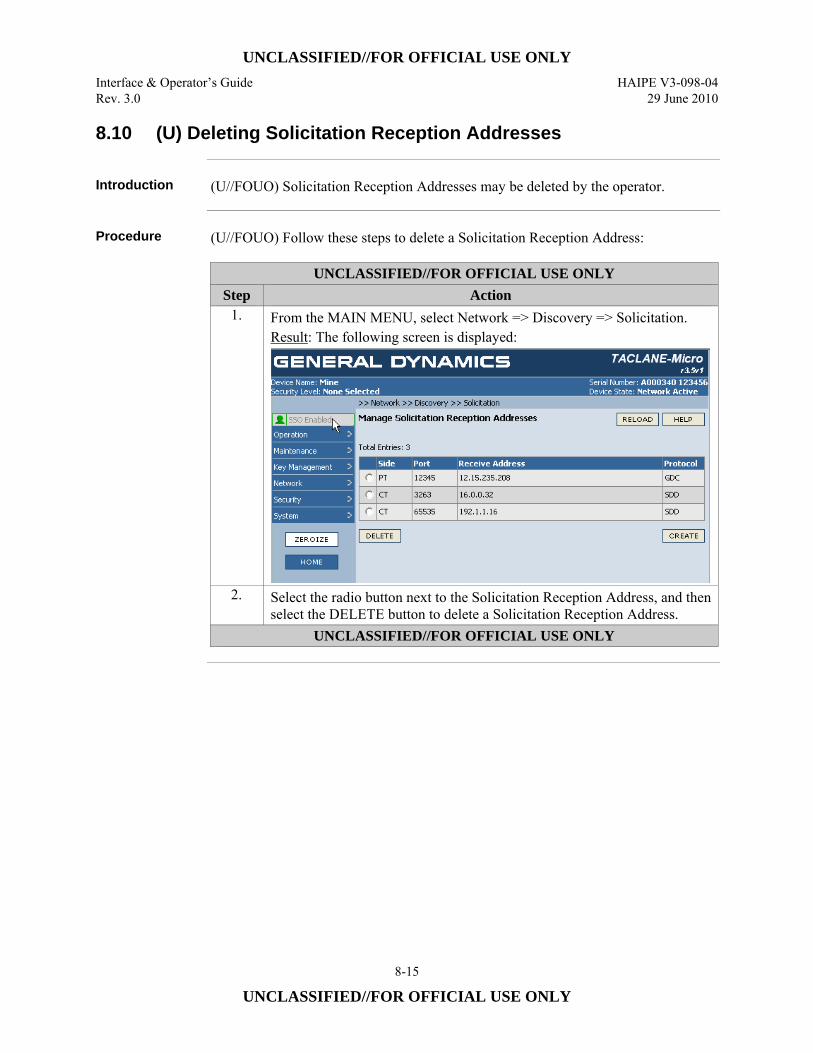
UNCLASSIFIED//FOR OFFICIAL USE ONLY Interface & Operator’s Guide HAIPE V3-098-04 Rev. 3.0 29 June 2010
8-15
UNCLASSIFIED//FOR OFFICIAL USE ONLY
8.10 (U) Deleting Solicitation Reception Addresses
Introduction (U//FOUO) Solicitation Reception Addresses may be deleted by the operator.
Procedure (U//FOUO) Follow these steps to delete a Solicitation Reception Address:
UNCLASSIFIED//FOR OFFICIAL USE ONLY Step Action
1. From the MAIN MENU, select Network => Discovery => Solicitation. Result: The following screen is displayed:
2. Select the radio button next to the Solicitation Reception Address, and then select the DELETE button to delete a Solicitation Reception Address.
UNCLASSIFIED//FOR OFFICIAL USE ONLY

UNCLASSIFIED//FOR OFFICIAL USE ONLY HAIPE V3-098-04 Interface & Operator’s Guide 29 June 2010 Rev. 3.0
8-16
UNCLASSIFIED//FOR OFFICIAL USE ONLY
(U) This page intentionally left blank.
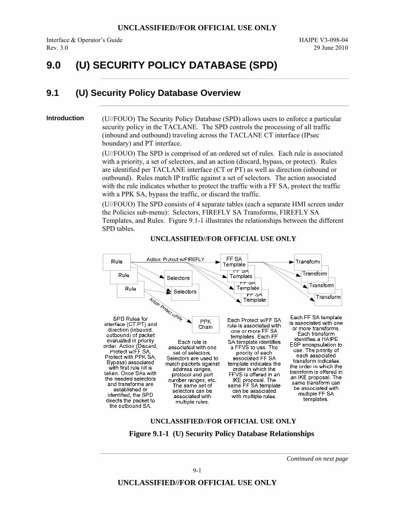
UNCLASSIFIED//FOR OFFICIAL USE ONLY Interface & Operator’s Guide HAIPE V3-098-04 Rev. 3.0 29 June 2010
9-1
UNCLASSIFIED//FOR OFFICIAL USE ONLY
9.0 (U) SECURITY POLICY DATABASE (SPD)
9.1 (U) Security Policy Database Overview
Introduction (U//FOUO) The Security Policy Database (SPD) allows users to enforce a particular
security policy in the TACLANE. The SPD controls the processing of all traffic (inbound and outbound) traveling across the TACLANE CT interface (IPsec boundary) and PT interface. (U//FOUO) The SPD is comprised of an ordered set of rules. Each rule is associated with a priority, a set of selectors, and an action (discard, bypass, or protect). Rules are identified per TACLANE interface (CT or PT) as well as direction (inbound or outbound). Rules match IP traffic against a set of selectors. The action associated with the rule indicates whether to protect the traffic with a FF SA, protect the traffic with a PPK SA, bypass the traffic, or discard the traffic. (U//FOUO) The SPD consists of 4 separate tables (each a separate HMI screen under the Policies sub-menu): Selectors, FIREFLY SA Transforms, FIREFLY SA Templates, and Rules. Figure 9.1-1 illustrates the relationships between the different SPD tables.
UNCLASSIFIED//FOR OFFICIAL USE ONLY
UNCLASSIFIED//FOR OFFICIAL USE ONLY
Figure 9.1-1 (U) Security Policy Database Relationships
Continued on next page
UNCLASSIFIED//FOR OFFICIAL USE ONLY HAIPE V3-098-04 Interface & Operator’s Guide 29 June 2010 Rev. 3.0
9-2
UNCLASSIFIED//FOR OFFICIAL USE ONLY
9.1 (U) Security Policy Database Overview, continued
Permanent and Default Rules
(U//FOUO) In addition to the operator-created SPD rules, there are also TACLANE ‘permanent’ rules which are used to enforce basic security behavior (e.g., filters invalid addresses) and reduce the need for some operator-created rules. Permanent rules cannot be modified or deleted by the operator. There are two rule priority ranges for the permanent rules: 1 – 255, and 65,280 – 65,535. Operator-created rules are in the 256 – 65,279 range. (U//FOUO) Default rules are essentially pre-populated operator rules. The default rules may be modified and deleted by the operator. The default rules also reduce the need for some operator-created rules. (U//FOUO) Appendix A provides a list of the permanent and default SPD rules.
9.2 (U) Steps to Securing Traffic with FIREFLY
FIREFLY Steps (U//FOUO) IP traffic can be secured using FIREFLY key. The steps for configuring
the SPD for supporting a FF SA include: • (U//FOUO) Configure at least one FIREFLY SA Transform (or use a default
Transform) – See Creating FIREFLY SA Transforms section
• (U//FOUO) Configure at least one FIREFLY SA Template – See Creating FIREFLY SA Templates section
• (U//FOUO) Configure a Selector (or use a default Selector) – See Creating Selectors section
• (U//FOUO) Configure an Outbound CT Protect w/ FIREFLY Rule – This allows the TACLANE to be an IKE initiator for FIREFLY SA
establishment to protect IP traffic – See Creating Rules section
• (U//FOUO) Configure an Inbound CT Protect w/ FIREFLY Rule – This allows the TACLANE to be an IKE responder for FIREFLY SA
establishment to protect IP traffic – See Creating Rules section
• (U//FOUO) See Appendix D for a specific example of creating a FIREFLY SA to secure IP traffic.
UNCLASSIFIED//FOR OFFICIAL USE ONLY Interface & Operator’s Guide HAIPE V3-098-04 Rev. 3.0 29 June 2010
9-3
UNCLASSIFIED//FOR OFFICIAL USE ONLY
9.3 (U) Steps to Securing Traffic with PPK
PPK Steps (U//FOUO) IP traffic can be secured using PPK. The steps for configuring a PPK SA
include: • (U//FOUO) Creating a PPK Chain
– See Chapter 4, Filling and Managing Keys • (U//FOUO) Configuring a PPK SA
– See Chapter 10, Configuring/Managing Security Associations • (U//FOUO) Configuring a Selector
– See Section 9.12, Creating Selectors section • (U//FOUO) Configuring an Outbound CT Protect with PPK Rule
– See Section 9.16, Creating Rules section • (U//FOUO) See Appendix D for a specific example of creating a PPK SA to
secure IP traffic.
9.4 (U) Creating FIREFLY SA Transforms
Introduction (U//FOUO) The SSO Operator can create FIREFLY SA Transforms for use during
FIREFLY SA establishment to negotiate how IP traffic will be protected.
Legacy, Suite A, and AES EFF FIREFLY SA Transforms
(U//FOUO) TACLANE supports configuration of “Legacy” (BATON BIP-32, MEDLEY BIP-32) FIREFLY SA Transforms for backwards-compatibility with HAIPE v1.3.5-compliant devices, as well as configuration of new HAIPE v3.1.2 Suite A and AES EFF FIREFLY SA Transforms. The operator chooses what combination of Legacy HAIPE v1.3.5 FIREFLY SA Transforms and/or new Suite A or AES EFF FIREFLY SA Transforms are offered during negotiation. The capability to simultaneously negotiate Legacy and Suite A or AES EFF FIREFLY SA Transforms supports a wide range of interoperability. This allows peer HAIPE v1.3.5-compliant devices to select from the Legacy HAIPE v1.3.5 FIREFLY SA Transforms (ignoring the newer HAIPE v3.1.2 Suite A and AES EFF FIREFLY SA Transforms) – while allowing peer HAIPE v3.1.2-compliant and greater devices to select from the new HAIPE v3.1.2 Suite A and AES EFF FIREFLY SA Transforms.
Grouping by Transform Name and Priority
(U//FOUO) FIREFLY SA Transforms are grouped by the Transform Name field. FIREFLY SA Transforms with the same Transform Name are in the same group, and each must have a unique Priority value within the group.
Continued on next page
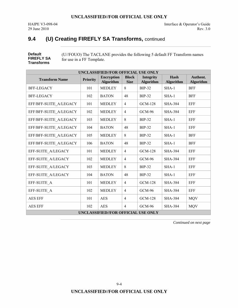
UNCLASSIFIED//FOR OFFICIAL USE ONLY HAIPE V3-098-04 Interface & Operator’s Guide 29 June 2010 Rev. 3.0
9-4
UNCLASSIFIED//FOR OFFICIAL USE ONLY
9.4 (U) Creating FIREFLY SA Transforms, continued
Default FIREFLY SA Transforms
(U//FOUO) The TACLANE provides the following 5 default FF Transform names for use in a FF Template.
UNCLASSIFIED//FOR OFFICIAL USE ONLY
Transform Name Priority Encryption Algorithm
Block Size
Integrity Algorithm
Hash Algorithm
Authent. Algorithm
BFF-LEGACY 101 MEDLEY 8 BIP-32 SHA-1 BFF
BFF-LEGACY 102 BATON 48 BIP-32 SHA-1 BFF
EFF/BFF-SUITE_A/LEGACY 101 MEDLEY 4 GCM-128 SHA-384 EFF
EFF/BFF-SUITE_A/LEGACY 102 MEDLEY 4 GCM-96 SHA-384 EFF
EFF/BFF-SUITE_A/LEGACY 103 MEDLEY 8 BIP-32 SHA-1 EFF
EFF/BFF-SUITE_A/LEGACY 104 BATON 48 BIP-32 SHA-1 EFF
EFF/BFF-SUITE_A/LEGACY 105 MEDLEY 8 BIP-32 SHA-1 BFF
EFF/BFF-SUITE_A/LEGACY 106 BATON 48 BIP-32 SHA-1 BFF
EFF-SUITE_A/LEGACY 101 MEDLEY 4 GCM-128 SHA-384 EFF
EFF-SUITE_A/LEGACY 102 MEDLEY 4 GCM-96 SHA-384 EFF
EFF-SUITE_A/LEGACY 103 MEDLEY 8 BIP-32 SHA-1 EFF
EFF-SUITE_A/LEGACY 104 BATON 48 BIP-32 SHA-1 EFF
EFF-SUITE_A 101 MEDLEY 4 GCM-128 SHA-384 EFF
EFF-SUITE_A 102 MEDLEY 4 GCM-96 SHA-384 EFF
AES EFF 101 AES 4 GCM-128 SHA-384 MQV
AES EFF 102 AES 4 GCM-96 SHA-384 MQV UNCLASSIFIED//FOR OFFICIAL USE ONLY
Continued on next page
UNCLASSIFIED//FOR OFFICIAL USE ONLY Interface & Operator’s Guide HAIPE V3-098-04 Rev. 3.0 29 June 2010
9-5
UNCLASSIFIED//FOR OFFICIAL USE ONLY
9.4 (U) Creating FIREFLY SA Transforms, continued
Notes (U//FOUO) The following notes apply to creating FIREFLY SA Transforms:
• (U//FOUO) Only the SSO can create a FIREFLY SA Transform. • (U//FOUO) Legacy FIREFLY SA Transforms can only be used to protect IPv4
traffic. • (U//FOUO) Legacy FIREFLY SA Transforms cannot be used for Transport
Mode SAs. • (U//FOUO) Up to 24 FIREFLY SA Transforms can be configured. • (U//FOUO) There are 16 default FIREFLY SA Transforms (see previous table),
however, these may be modified/deleted. • (U//FOUO) Multiple FIREFLY SA Templates can be associated with the same
set of FIREFLY SA Transforms. • (U//FOUO) FIREFLY SA Transforms can be created/modified with or without
being associated with one or more FIREFLY SA Templates. • (U//FOUO) If a FIREFLY SA Template is already associated with the
Transform Name, any new FIREFLY SA Transform using that Transform Name must match the capabilities of the FIREFLY Vector Set associated with the FIREFLY SA Template. (See Creating FIREFLY SA Templates for rules on ordering Transforms.)
• (U//FOUO) HAIPE v3.1.2 only supports FIREFLY SAs using MTEK/MTEK update. Ensure that MTEK/MTEK update is enabled on pre-HAIPE v3.1.2 devices (or pre-Release 3.5 TACLANEs) to ensure interoperability.
Continued on next page
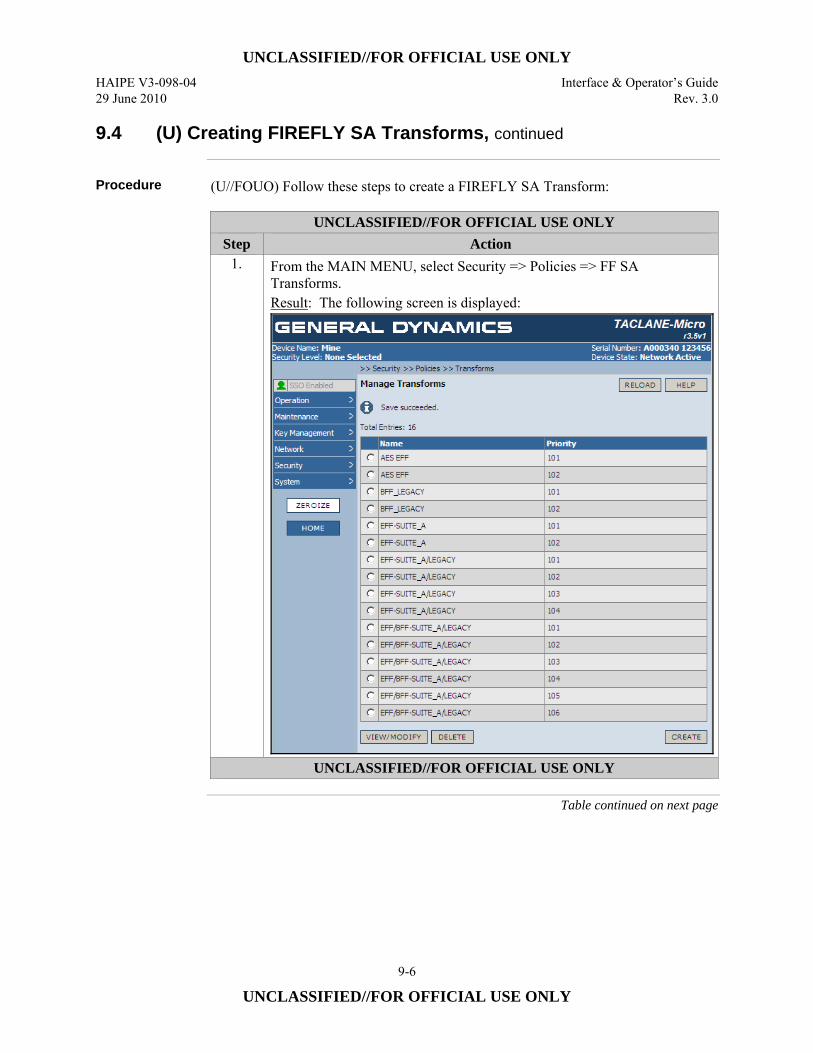
UNCLASSIFIED//FOR OFFICIAL USE ONLY HAIPE V3-098-04 Interface & Operator’s Guide 29 June 2010 Rev. 3.0
9-6
UNCLASSIFIED//FOR OFFICIAL USE ONLY
9.4 (U) Creating FIREFLY SA Transforms, continued
Procedure (U//FOUO) Follow these steps to create a FIREFLY SA Transform:
UNCLASSIFIED//FOR OFFICIAL USE ONLY Step Action
1. From the MAIN MENU, select Security => Policies => FF SA Transforms. Result: The following screen is displayed:
UNCLASSIFIED//FOR OFFICIAL USE ONLY
Table continued on next page
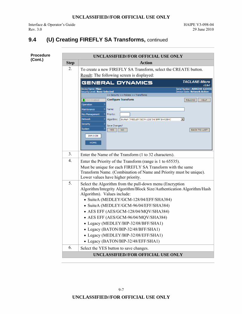
UNCLASSIFIED//FOR OFFICIAL USE ONLY Interface & Operator’s Guide HAIPE V3-098-04 Rev. 3.0 29 June 2010
9-7
UNCLASSIFIED//FOR OFFICIAL USE ONLY
9.4 (U) Creating FIREFLY SA Transforms, continued
Procedure (Cont.)
UNCLASSIFIED//FOR OFFICIAL USE ONLY Step Action
2. To create a new FIREFLY SA Transform, select the CREATE button. Result: The following screen is displayed:
3. Enter the Name of the Transform (1 to 32 characters). 4. Enter the Priority of the Transform (range is 1 to 65535).
Must be unique for each FIREFLY SA Transform with the same Transform Name. (Combination of Name and Priority must be unique). Lower values have higher priority.
5. Select the Algorithm from the pull-down menu (Encryption Algorithm/Integrity Algorithm/Block Size/Authentication Algorithm/Hash Algorithm). Values include: • SuiteA (MEDLEY/GCM-128/04/EFF/SHA384) • SuiteA (MEDLEY/GCM-96/04/EFF/SHA384) • AES EFF (AES/GCM-128/04/MQV/SHA384) • AES EFF (AES/GCM-96/04/MQV/SHA384) • Legacy (MEDLEY/BIP-32/08/BFF/SHA1) • Legacy (BATON/BIP-32/48/BFF/SHA1) • Legacy (MEDLEY/BIP-32/08/EFF/SHA1) • Legacy (BATON/BIP-32/48/EFF/SHA1)
6. Select the YES button to save changes. UNCLASSIFIED//FOR OFFICIAL USE ONLY

UNCLASSIFIED//FOR OFFICIAL USE ONLY HAIPE V3-098-04 Interface & Operator’s Guide 29 June 2010 Rev. 3.0
9-8
UNCLASSIFIED//FOR OFFICIAL USE ONLY
9.5 (U) Modifying FIREFLY SA Transforms
Introduction (U//FOUO) The SSO Operator can modify FIREFLY SA Transforms for use during
FIREFLY SA establishment to negotiate how IP traffic will be protected.
Notes (U//FOUO) The following notes apply to modifying FIREFLY SA Transforms:
• Only the SSO can modify the FIREFLY SA Transform. • Legacy FIREFLY SA Transforms can only be used to protect IPv4 traffic. • FIREFLY SA Transforms can be created/modified with or without being
associated with one or more FIREFLY SA Templates. • (U//FOUO) Legacy FIREFLY SA Transforms cannot be assigned to Transport
Mode FIREFLY SA Templates. • Refer to the Creating FIREFLY SA Transforms section for more information.
Continued on next page
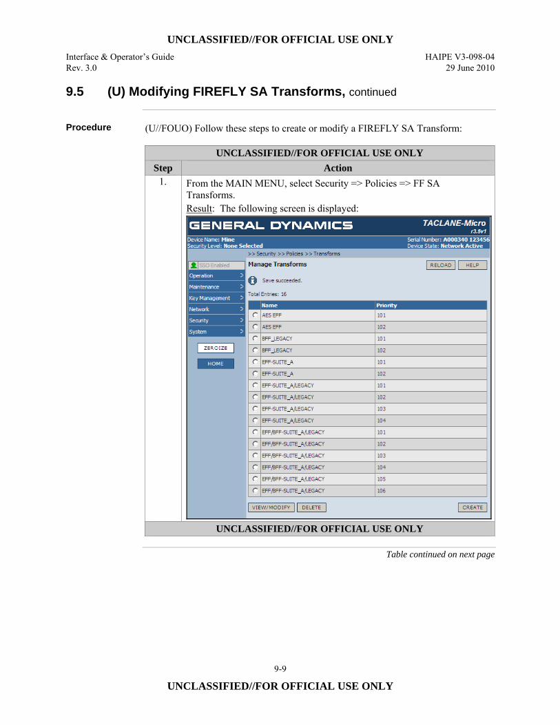
UNCLASSIFIED//FOR OFFICIAL USE ONLY Interface & Operator’s Guide HAIPE V3-098-04 Rev. 3.0 29 June 2010
9-9
UNCLASSIFIED//FOR OFFICIAL USE ONLY
9.5 (U) Modifying FIREFLY SA Transforms, continued
Procedure (U//FOUO) Follow these steps to create or modify a FIREFLY SA Transform:
UNCLASSIFIED//FOR OFFICIAL USE ONLY Step Action
1. From the MAIN MENU, select Security => Policies => FF SA Transforms. Result: The following screen is displayed:
UNCLASSIFIED//FOR OFFICIAL USE ONLY
Table continued on next page
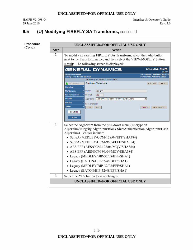
UNCLASSIFIED//FOR OFFICIAL USE ONLY HAIPE V3-098-04 Interface & Operator’s Guide 29 June 2010 Rev. 3.0
9-10
UNCLASSIFIED//FOR OFFICIAL USE ONLY
9.5 (U) Modifying FIREFLY SA Transforms, continued
Procedure (Cont.)
UNCLASSIFIED//FOR OFFICIAL USE ONLY Step Action
2. To modify an existing FIREFLY SA Transform, select the radio button next to the Transform name, and then select the VIEW/MODIFY button. Result: The following screen is displayed:
3. Select the Algorithm from the pull-down menu (Encryption Algorithm/Integrity Algorithm/Block Size/Authentication Algorithm/Hash Algorithm). Values include: • SuiteA (MEDLEY/GCM-128/04/EFF/SHA384) • SuiteA (MEDLEY/GCM-96/04/EFF/SHA384) • AES EFF (AES/GCM-128/04/MQV/SHA384) • AES EFF (AES/GCM-96/04/MQV/SHA384) • Legacy (MEDLEY/BIP-32/08/BFF/SHA1) • Legacy (BATON/BIP-32/48/BFF/SHA1) • Legacy (MEDLEY/BIP-32/08/EFF/SHA1) • Legacy (BATON/BIP-32/48/EFF/SHA1)
4. Select the YES button to save changes. UNCLASSIFIED//FOR OFFICIAL USE ONLY
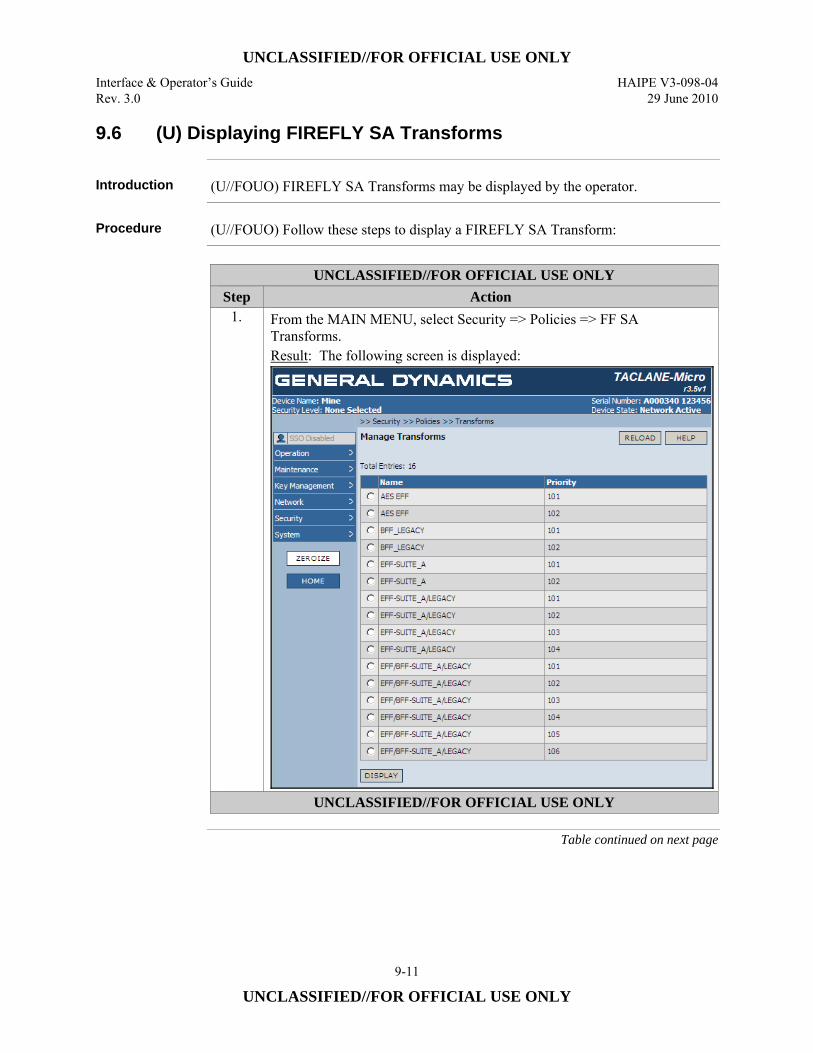
UNCLASSIFIED//FOR OFFICIAL USE ONLY Interface & Operator’s Guide HAIPE V3-098-04 Rev. 3.0 29 June 2010
9-11
UNCLASSIFIED//FOR OFFICIAL USE ONLY
9.6 (U) Displaying FIREFLY SA Transforms
Introduction (U//FOUO) FIREFLY SA Transforms may be displayed by the operator.
Procedure (U//FOUO) Follow these steps to display a FIREFLY SA Transform:
UNCLASSIFIED//FOR OFFICIAL USE ONLY
Step Action 1. From the MAIN MENU, select Security => Policies => FF SA
Transforms. Result: The following screen is displayed:
UNCLASSIFIED//FOR OFFICIAL USE ONLY
Table continued on next page
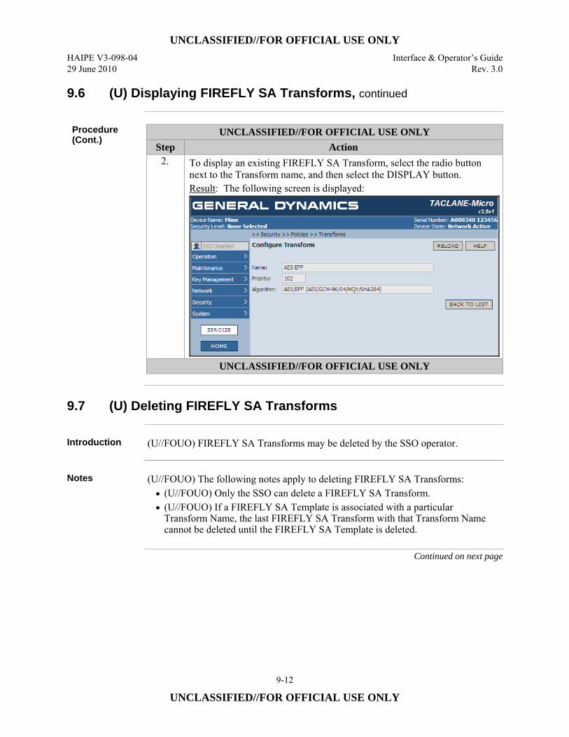
UNCLASSIFIED//FOR OFFICIAL USE ONLY HAIPE V3-098-04 Interface & Operator’s Guide 29 June 2010 Rev. 3.0
9-12
UNCLASSIFIED//FOR OFFICIAL USE ONLY
9.6 (U) Displaying FIREFLY SA Transforms, continued
Procedure (Cont.)
UNCLASSIFIED//FOR OFFICIAL USE ONLY Step Action
2. To display an existing FIREFLY SA Transform, select the radio button next to the Transform name, and then select the DISPLAY button. Result: The following screen is displayed:
UNCLASSIFIED//FOR OFFICIAL USE ONLY
9.7 (U) Deleting FIREFLY SA Transforms
Introduction (U//FOUO) FIREFLY SA Transforms may be deleted by the SSO operator.
Notes (U//FOUO) The following notes apply to deleting FIREFLY SA Transforms:
• (U//FOUO) Only the SSO can delete a FIREFLY SA Transform. • (U//FOUO) If a FIREFLY SA Template is associated with a particular
Transform Name, the last FIREFLY SA Transform with that Transform Name cannot be deleted until the FIREFLY SA Template is deleted.
Continued on next page
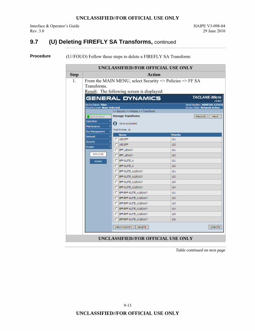
UNCLASSIFIED//FOR OFFICIAL USE ONLY Interface & Operator’s Guide HAIPE V3-098-04 Rev. 3.0 29 June 2010
9-13
UNCLASSIFIED//FOR OFFICIAL USE ONLY
9.7 (U) Deleting FIREFLY SA Transforms, continued
Procedure (U//FOUO) Follow these steps to delete a FIREFLY SA Transform:
UNCLASSIFIED//FOR OFFICIAL USE ONLY Step Action
1. From the MAIN MENU, select Security => Policies => FF SA Transforms. Result: The following screen is displayed:
UNCLASSIFIED//FOR OFFICIAL USE ONLY
Table continued on next page
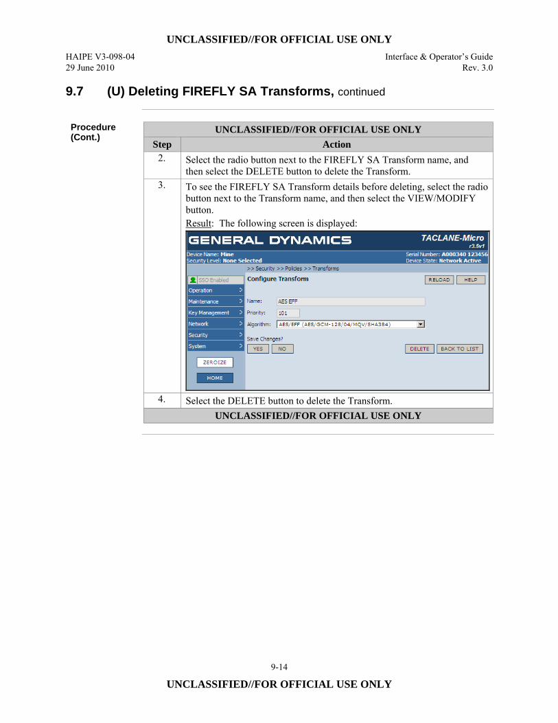
UNCLASSIFIED//FOR OFFICIAL USE ONLY HAIPE V3-098-04 Interface & Operator’s Guide 29 June 2010 Rev. 3.0
9-14
UNCLASSIFIED//FOR OFFICIAL USE ONLY
9.7 (U) Deleting FIREFLY SA Transforms, continued
Procedure (Cont.)
UNCLASSIFIED//FOR OFFICIAL USE ONLY Step Action
2. Select the radio button next to the FIREFLY SA Transform name, and then select the DELETE button to delete the Transform.
3. To see the FIREFLY SA Transform details before deleting, select the radio button next to the Transform name, and then select the VIEW/MODIFY button. Result: The following screen is displayed:
4. Select the DELETE button to delete the Transform. UNCLASSIFIED//FOR OFFICIAL USE ONLY
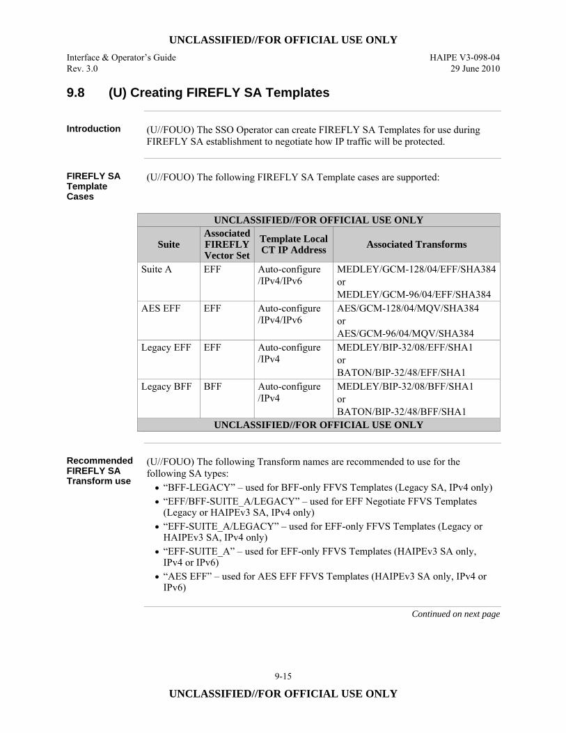
UNCLASSIFIED//FOR OFFICIAL USE ONLY Interface & Operator’s Guide HAIPE V3-098-04 Rev. 3.0 29 June 2010
9-15
UNCLASSIFIED//FOR OFFICIAL USE ONLY
9.8 (U) Creating FIREFLY SA Templates
Introduction (U//FOUO) The SSO Operator can create FIREFLY SA Templates for use during
FIREFLY SA establishment to negotiate how IP traffic will be protected.
FIREFLY SA Template Cases
(U//FOUO) The following FIREFLY SA Template cases are supported:
UNCLASSIFIED//FOR OFFICIAL USE ONLY
Suite Associated FIREFLY Vector Set
Template Local CT IP Address Associated Transforms
Suite A EFF Auto-configure /IPv4/IPv6
MEDLEY/GCM-128/04/EFF/SHA384 or MEDLEY/GCM-96/04/EFF/SHA384
AES EFF EFF Auto-configure /IPv4/IPv6
AES/GCM-128/04/MQV/SHA384 or AES/GCM-96/04/MQV/SHA384
Legacy EFF EFF Auto-configure /IPv4
MEDLEY/BIP-32/08/EFF/SHA1 or BATON/BIP-32/48/EFF/SHA1
Legacy BFF BFF Auto-configure /IPv4
MEDLEY/BIP-32/08/BFF/SHA1 or BATON/BIP-32/48/BFF/SHA1
UNCLASSIFIED//FOR OFFICIAL USE ONLY
Recommended FIREFLY SA Transform use
(U//FOUO) The following Transform names are recommended to use for the following SA types: • “BFF-LEGACY” – used for BFF-only FFVS Templates (Legacy SA, IPv4 only) • “EFF/BFF-SUITE_A/LEGACY” – used for EFF Negotiate FFVS Templates
(Legacy or HAIPEv3 SA, IPv4 only) • “EFF-SUITE_A/LEGACY” – used for EFF-only FFVS Templates (Legacy or
HAIPEv3 SA, IPv4 only) • “EFF-SUITE_A” – used for EFF-only FFVS Templates (HAIPEv3 SA only,
IPv4 or IPv6) • “AES EFF” – used for AES EFF FFVS Templates (HAIPEv3 SA only, IPv4 or
IPv6)
Continued on next page
UNCLASSIFIED//FOR OFFICIAL USE ONLY HAIPE V3-098-04 Interface & Operator’s Guide 29 June 2010 Rev. 3.0
9-16
UNCLASSIFIED//FOR OFFICIAL USE ONLY
9.8 (U) Creating FIREFLY SA Templates, continued
Per-FIREFLY SA Traffic Flow Security
(U//FOUO) The TACLANE supports per-FIREFLY SA IP Traffic Flow Security (TFS) features that are required by the HAIPE Interoperability Specification (IS). When configured appropriately, the IP TFS features in the TACLANE prevent/ reduce compromise of sensitive information due to certain types of attacks. The per-FIREFLY SA TFS settings include: • DF Bit Bypass • ECN Bypass • DSCP Bypass • Flow Label Bypass
(U//FOUO) There are important security and performance trade-offs that should be considered when configuring TFS countermeasures. For descriptions of these trade-offs, along with recommended network and equipment configurations that minimize security risks, please refer to the TACLANE Security Features Users Guide.
DF Bit Bypass (U//FOUO) Don’t Fragment (DF) bit bypass is used to support PMTU discovery.
The DF Bit bypass parameter can be configured on a per-FIREFLY SA basis in one of three ways: • SET: Always sets the DF bit in the CT IP header to “1”. • CLEAR: Always sets the DF bit in the CT IP header to “0”. • COPY: Copies the DF bit value from the PT IP header to the CT ESP IP header
DF bit value. (U//FOUO) The DF bit bypass setting has no effect on IPv6 SAs, as the DF bit does not exist in IPv6.
Flow Label Bypass
(U//FOUO) Flow Label Bypass only applies to IPv6 traffic. Enabling Flow Label bypass permits the 20-bit Flow Label field in the IPv6 Header to be bypassed from the PT interface to the CT interface. Disabling Flow Label bypass blocks the Flow Label value from being bypassed in the PT to CT direction. The TACLANE sets the Flow Label value to 0 on the CT interface. Flow Label bypass only applies to traffic traveling from the PT interface to the CT interface: • (U//FOUO) OFF: Flow Label not bypassed, value is set to 0. • (U//FOUO) ON: Flow Label value is bypassed from the PT side to the CT side.
Continued on next page
UNCLASSIFIED//FOR OFFICIAL USE ONLY Interface & Operator’s Guide HAIPE V3-098-04 Rev. 3.0 29 June 2010
9-17
UNCLASSIFIED//FOR OFFICIAL USE ONLY
9.8 (U) Creating FIREFLY SA Templates, continued
ECN Bypass (U//FOUO) Explicit Congestion Notification (ECN) bypass can be used to support
network congestion control. ECN bypass can be configured on a per-FIREFLY SA basis in one of three ways: • (U//FOUO) OFF:
– Always sets the ECN bits in the CT ESP IP header to “10” binary. – For a Transport Mode SA, the reconstructed PT IP header ECN bits are set
to “00” before the PT IP datagram is sent on the PT network. • (U//FOUO) ON-CONGESTION:
– Always sets the ECN bits in the CT ESP IP header to “10” binary. – For a Tunnel Mode SA, if the received CT ESP IP header ECN bits are “11”,
and the decrypted PT IP header ECN bits are “10” or “01”, the decrypted PT IP header ECN bits are changed to “11” before the PT IP datagram is sent on the PT network.
– For a Transport Mode SA, if the received CT ESP IP header ECN bits are “11”, the reconstructed PT IP header ECN bits are set to “11” before the PT IP datagram is sent on the PT network.
– For a Transport Mode SA, if the received CT ESP IP header ECN bits are “10”, “00”, or “01”, the reconstructed PT IP header ECN bits are set to “10” before the PT IP datagram is sent on the PT network.
• ON-ADMISSION: – Copies the ECN bits from the PT IP header to the CT IP header. – Copies the ECN bits from the CT IP header to the PT IP header.
DSCP Bypass (U//FOUO) Differentiated Services Code Point (DSCP) bypass is configurable on a
per-FIREFLY SA basis. Each FIREFLY SA Template can be configured to either: • (U//FOUO) DISABLED – overwrite CT DSCP value to zero. This DSCP value
is used in the CT ESP IP header for all ESP traffic generated using a FIREFLY SA established using the Template.
• (U//FOUO) ENABLED – select which of the 64 DSCP values allowed to be bypassed. Any allowed bypass value is copied from the PT IP header to the CT ESP IP header.
Continued on next page
UNCLASSIFIED//FOR OFFICIAL USE ONLY HAIPE V3-098-04 Interface & Operator’s Guide 29 June 2010 Rev. 3.0
9-18
UNCLASSIFIED//FOR OFFICIAL USE ONLY
9.8 (U) Creating FIREFLY SA Templates, continued
Notes (U//FOUO) The following notes apply to creating FIREFLY SA Templates:
• (U//FOUO) Only the SSO can access this command. • (U//FOUO) Up to 24 FIREFLY SA Templates can be configured. • (U//FOUO) Multiple Rules can be associated with the same set of FIREFLY SA
Templates. • (U//FOUO) A maximum of 13 FIREFLY SA Templates can be created with the
same FIREFLY SA Template Name. • (U//FOUO) At least one FIREFLY SA Transform of a particular Transform
Name must exist in order to create a FIREFLY SA Template associated with that Transform Name.
• (U//FOUO) A Legacy FIREFLY SA Transform cannot be assigned to a Transport Mode FIREFLY SA Template.
• (U//FOUO) FIREFLY SA Templates with the same name can have different connection types (i.e., for negotiation of tunnel or transport mode security associations).
• (U//FOUO) Transport Mode FIREFLY SA Templates cannot be created if FPL is enabled.
• (U//FOUO) At least one FIREFLY Vector Set of the desired Universal ID must be filled before creating FIREFLY SA Templates.
• (U//FOUO) FIREFLY SA Templates of the same Template Name: – Must be ordered by Priority from lowest Universal ID to highest Universal
ID – Must all have the same Template Local CT IP address. I.e., either all are
Auto-configure, all are the same given valid local CT IPv4 address, or all are the same given valid local CT IPv6 address
– (Combination of Template Name and Priority must be unique for each FIREFLY SA Template.)
• (U//FOUO) If CT Stateless Address Autoconfiguration (SAA) and Duplicate Address Detection (DAD) are enabled, only Auto-configure is allowed for Local CT IPv6 Addresses in the Template.
• (U//FOUO) If the associated FIREFLY Vector Set is a “Current/Next” FIREFLY Vector Set, at least the “Next” must be used during FIREFLY SA establishment. If only the Universal ID is specified, both Next and Current are automatically used during FIREFLY SA establishment. If the Universal Edition and KMID are specified, at least the Universal Edition and KMID of the Next must be included in a FIREFLY SA Template.
Continued on next page
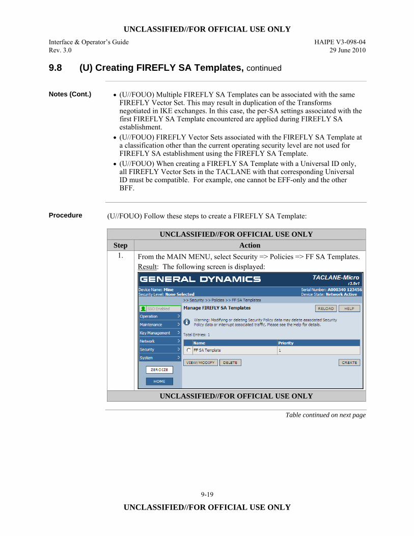
UNCLASSIFIED//FOR OFFICIAL USE ONLY Interface & Operator’s Guide HAIPE V3-098-04 Rev. 3.0 29 June 2010
9-19
UNCLASSIFIED//FOR OFFICIAL USE ONLY
9.8 (U) Creating FIREFLY SA Templates, continued
Notes (Cont.) • (U//FOUO) Multiple FIREFLY SA Templates can be associated with the same
FIREFLY Vector Set. This may result in duplication of the Transforms negotiated in IKE exchanges. In this case, the per-SA settings associated with the first FIREFLY SA Template encountered are applied during FIREFLY SA establishment.
• (U//FOUO) FIREFLY Vector Sets associated with the FIREFLY SA Template at a classification other than the current operating security level are not used for FIREFLY SA establishment using the FIREFLY SA Template.
• (U//FOUO) When creating a FIREFLY SA Template with a Universal ID only, all FIREFLY Vector Sets in the TACLANE with that corresponding Universal ID must be compatible. For example, one cannot be EFF-only and the other BFF.
Procedure (U//FOUO) Follow these steps to create a FIREFLY SA Template:
UNCLASSIFIED//FOR OFFICIAL USE ONLY Step Action
1. From the MAIN MENU, select Security => Policies => FF SA Templates. Result: The following screen is displayed:
UNCLASSIFIED//FOR OFFICIAL USE ONLY
Table continued on next page
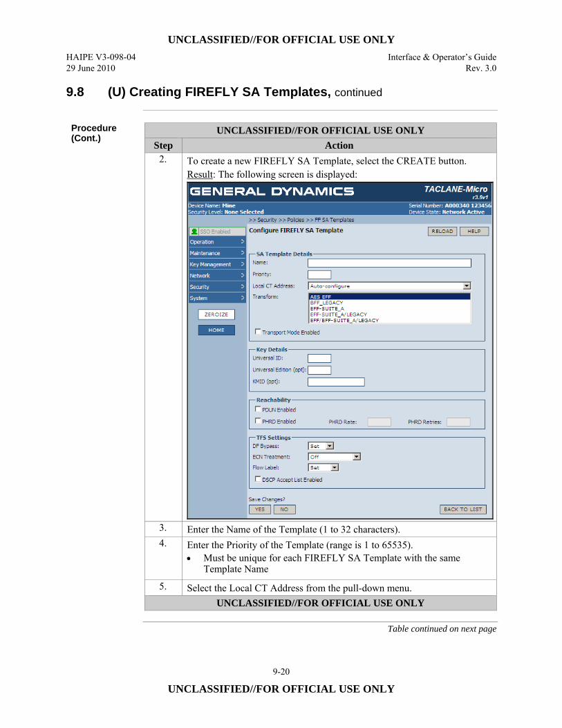
UNCLASSIFIED//FOR OFFICIAL USE ONLY HAIPE V3-098-04 Interface & Operator’s Guide 29 June 2010 Rev. 3.0
9-20
UNCLASSIFIED//FOR OFFICIAL USE ONLY
9.8 (U) Creating FIREFLY SA Templates, continued
Procedure (Cont.)
UNCLASSIFIED//FOR OFFICIAL USE ONLY Step Action
2. To create a new FIREFLY SA Template, select the CREATE button. Result: The following screen is displayed:
3. Enter the Name of the Template (1 to 32 characters). 4. Enter the Priority of the Template (range is 1 to 65535).
• Must be unique for each FIREFLY SA Template with the same Template Name
5. Select the Local CT Address from the pull-down menu. UNCLASSIFIED//FOR OFFICIAL USE ONLY
Table continued on next page
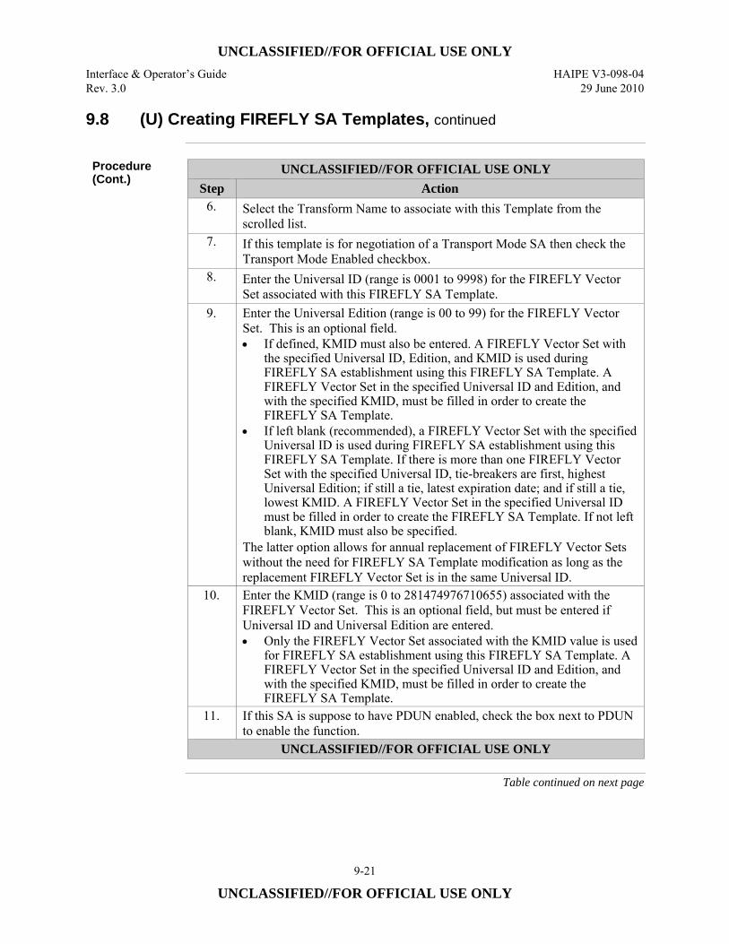
UNCLASSIFIED//FOR OFFICIAL USE ONLY Interface & Operator’s Guide HAIPE V3-098-04 Rev. 3.0 29 June 2010
9-21
UNCLASSIFIED//FOR OFFICIAL USE ONLY
9.8 (U) Creating FIREFLY SA Templates, continued
Procedure (Cont.)
UNCLASSIFIED//FOR OFFICIAL USE ONLY Step Action
6. Select the Transform Name to associate with this Template from the scrolled list.
7. If this template is for negotiation of a Transport Mode SA then check the Transport Mode Enabled checkbox.
8. Enter the Universal ID (range is 0001 to 9998) for the FIREFLY Vector Set associated with this FIREFLY SA Template.
9. Enter the Universal Edition (range is 00 to 99) for the FIREFLY Vector Set. This is an optional field. • If defined, KMID must also be entered. A FIREFLY Vector Set with
the specified Universal ID, Edition, and KMID is used during FIREFLY SA establishment using this FIREFLY SA Template. A FIREFLY Vector Set in the specified Universal ID and Edition, and with the specified KMID, must be filled in order to create the FIREFLY SA Template.
• If left blank (recommended), a FIREFLY Vector Set with the specified Universal ID is used during FIREFLY SA establishment using this FIREFLY SA Template. If there is more than one FIREFLY Vector Set with the specified Universal ID, tie-breakers are first, highest Universal Edition; if still a tie, latest expiration date; and if still a tie, lowest KMID. A FIREFLY Vector Set in the specified Universal ID must be filled in order to create the FIREFLY SA Template. If not left blank, KMID must also be specified.
The latter option allows for annual replacement of FIREFLY Vector Sets without the need for FIREFLY SA Template modification as long as the replacement FIREFLY Vector Set is in the same Universal ID.
10. Enter the KMID (range is 0 to 281474976710655) associated with the FIREFLY Vector Set. This is an optional field, but must be entered if Universal ID and Universal Edition are entered. • Only the FIREFLY Vector Set associated with the KMID value is used
for FIREFLY SA establishment using this FIREFLY SA Template. A FIREFLY Vector Set in the specified Universal ID and Edition, and with the specified KMID, must be filled in order to create the FIREFLY SA Template.
11. If this SA is suppose to have PDUN enabled, check the box next to PDUN to enable the function.
UNCLASSIFIED//FOR OFFICIAL USE ONLY
Table continued on next page
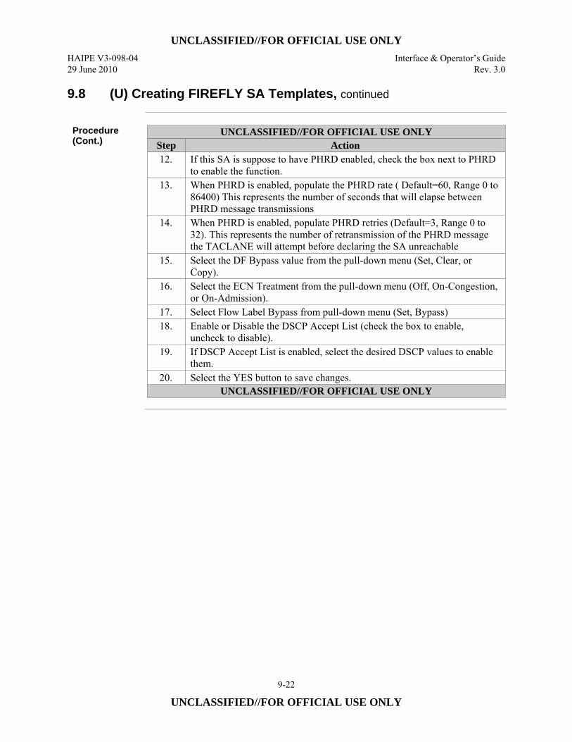
UNCLASSIFIED//FOR OFFICIAL USE ONLY HAIPE V3-098-04 Interface & Operator’s Guide 29 June 2010 Rev. 3.0
9-22
UNCLASSIFIED//FOR OFFICIAL USE ONLY
9.8 (U) Creating FIREFLY SA Templates, continued
Procedure (Cont.)
UNCLASSIFIED//FOR OFFICIAL USE ONLY Step Action 12. If this SA is suppose to have PHRD enabled, check the box next to PHRD
to enable the function. 13. When PHRD is enabled, populate the PHRD rate ( Default=60, Range 0 to
86400) This represents the number of seconds that will elapse between PHRD message transmissions
14. When PHRD is enabled, populate PHRD retries (Default=3, Range 0 to 32). This represents the number of retransmission of the PHRD message the TACLANE will attempt before declaring the SA unreachable
15. Select the DF Bypass value from the pull-down menu (Set, Clear, or Copy).
16. Select the ECN Treatment from the pull-down menu (Off, On-Congestion, or On-Admission).
17. Select Flow Label Bypass from pull-down menu (Set, Bypass) 18. Enable or Disable the DSCP Accept List (check the box to enable,
uncheck to disable). 19. If DSCP Accept List is enabled, select the desired DSCP values to enable
them. 20. Select the YES button to save changes.
UNCLASSIFIED//FOR OFFICIAL USE ONLY
UNCLASSIFIED//FOR OFFICIAL USE ONLY Interface & Operator’s Guide HAIPE V3-098-04 Rev. 3.0 29 June 2010
9-23
UNCLASSIFIED//FOR OFFICIAL USE ONLY
9.9 (U) Modifying FIREFLY SA Templates
Introduction (U//FOUO) The SSO Operator can modify FIREFLY SA Templates for use during
FIREFLY SA establishment to negotiate how IP traffic will be protected.
Notes (U//FOUO) The following notes apply to modifying FIREFLY SA Templates:
• (U//FOUO) Only the SSO can modify a FIREFLY SA Template. • (U//FOUO) FIREFLY SA Templates of the same Template Name:
– Must be ordered by Priority from lowest Universal ID to highest Universal ID
– Must all have the same Template Local CT IP Address. I.e., either all are Auto-configure, all are the same given valid local CT IPv4 address, or all are the same given valid local CT IPv6 address
– (Combination of Template Name and Priority must be unique for each FIREFLY SA Template.)
• (U//FOUO) If CT Stateless Address Autoconfiguration (SAA) and Duplicate Address Detection (DAD) are enabled, only Auto-configure Template Local CT IPv6 Addresses are allowed.
• (U//FOUO) A Legacy FIREFLY SA Transform cannot be assigned to a Transport Mode FIREFLY SA Template.
• (U//FOUO) Refer to the Creating FIREFLY SA Templates section for more information.
Continued on next page
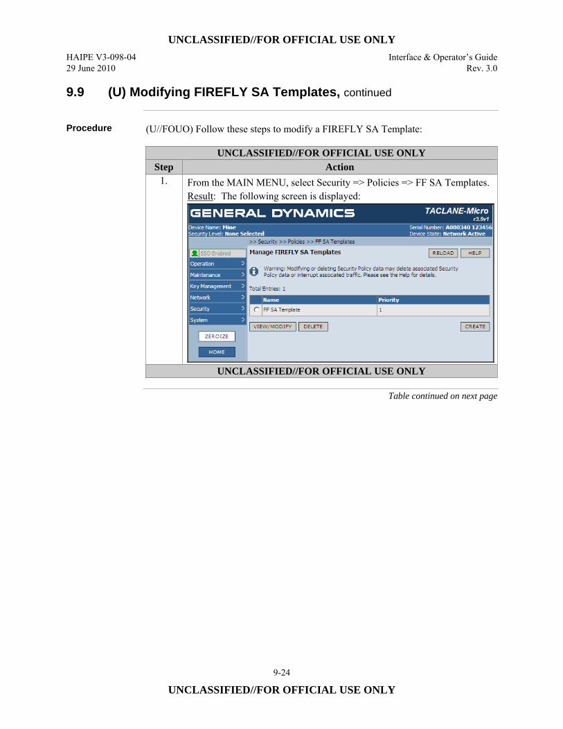
UNCLASSIFIED//FOR OFFICIAL USE ONLY HAIPE V3-098-04 Interface & Operator’s Guide 29 June 2010 Rev. 3.0
9-24
UNCLASSIFIED//FOR OFFICIAL USE ONLY
9.9 (U) Modifying FIREFLY SA Templates, continued
Procedure (U//FOUO) Follow these steps to modify a FIREFLY SA Template:
UNCLASSIFIED//FOR OFFICIAL USE ONLY Step Action
1. From the MAIN MENU, select Security => Policies => FF SA Templates. Result: The following screen is displayed:
UNCLASSIFIED//FOR OFFICIAL USE ONLY
Table continued on next page
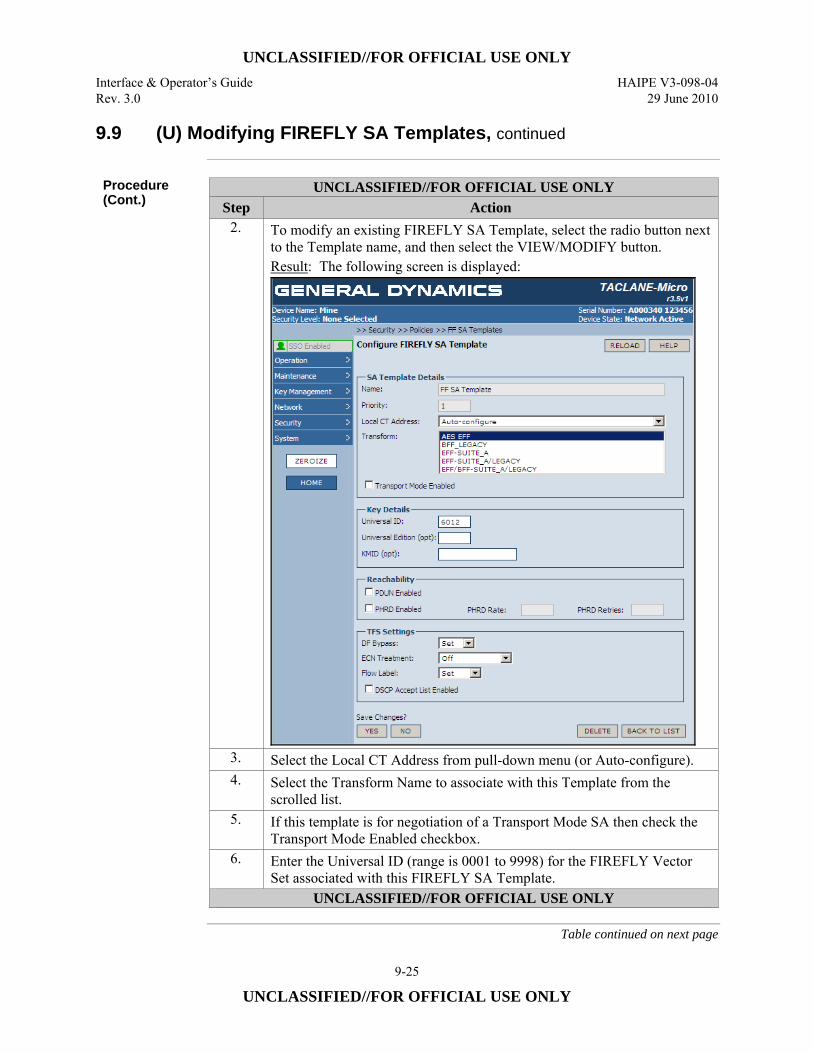
UNCLASSIFIED//FOR OFFICIAL USE ONLY Interface & Operator’s Guide HAIPE V3-098-04 Rev. 3.0 29 June 2010
9-25
UNCLASSIFIED//FOR OFFICIAL USE ONLY
9.9 (U) Modifying FIREFLY SA Templates, continued
Procedure (Cont.)
UNCLASSIFIED//FOR OFFICIAL USE ONLY Step Action
2. To modify an existing FIREFLY SA Template, select the radio button next to the Template name, and then select the VIEW/MODIFY button. Result: The following screen is displayed:
3. Select the Local CT Address from pull-down menu (or Auto-configure). 4. Select the Transform Name to associate with this Template from the
scrolled list. 5. If this template is for negotiation of a Transport Mode SA then check the
Transport Mode Enabled checkbox. 6. Enter the Universal ID (range is 0001 to 9998) for the FIREFLY Vector
Set associated with this FIREFLY SA Template. UNCLASSIFIED//FOR OFFICIAL USE ONLY
Table continued on next page
UNCLASSIFIED//FOR OFFICIAL USE ONLY HAIPE V3-098-04 Interface & Operator’s Guide 29 June 2010 Rev. 3.0
9-26
UNCLASSIFIED//FOR OFFICIAL USE ONLY
9.9 (U) Modifying FIREFLY SA Templates, continued
Procedure (Cont.)
UNCLASSIFIED//FOR OFFICIAL USE ONLY Step Action
7. Enter the Universal Edition (range is 00 to 99) for the FIREFLY Vector Set. This is an optional field. • If defined, KMID must also be entered. A FIREFLY Vector Set with
the specified Universal ID, Edition, and KMID is used during FIREFLY SA establishment using this FIREFLY SA Template. A FIREFLY Vector Set in the specified Universal ID and Edition, and with the specified KMID, must be filled in order to create the FIREFLY SA Template.
• If left blank (recommended), a FIREFLY Vector Set with the specified Universal ID is used during FIREFLY SA establishment using this FIREFLY SA Template. If there is more than one FIREFLY Vector Set with the specified Universal ID, tie-breakers are first, highest Universal Edition; if still a tie, latest expiration date; and if still a tie, lowest KMID. A FIREFLY Vector Set in the specified Universal ID must be filled in order to create the FIREFLY SA Template. If not left blank, KMID must also be specified.
• The latter option allows for annual replacement of FIREFLY Vector Sets without the need for FIREFLY SA Template modification as long as the replacement FIREFLY Vector Set is in the same Universal ID.
8. Enter the KMID (range is 0 to 281474976710655) associated with the FIREFLY Vector Set. This is an optional field, but must be entered if Universal ID and Universal Edition are entered. • Only the FIREFLY Vector Set associated with the KMID value is used
for FIREFLY SA establishment using this FIREFLY SA Template. A FIREFLY Vector Set in the specified Universal ID and Edition, and with the specified KMID, must be filled in order to create the FIREFLY SA Template.
9. If this SA is suppose to have PDUN enabled, check the box next to PDUN to enable the function
10. If this SA is suppose to have PHRD enabled, check the box next to PHRD to enable the function.
11. When PHRD is enabled, populate the PHRD rate ( Default=60, Range 0 to 86400) This represents the number of seconds that will elapse between PHRD message transmissions
12. When PHRD is enabled, populate PHRD retries (Default=3, Range 0 to 32). This represents the number of retransmission of the PHRD message the TACLANE will attempt before declaring the SA unreachable
UNCLASSIFIED//FOR OFFICIAL USE ONLY
Table continued on next page
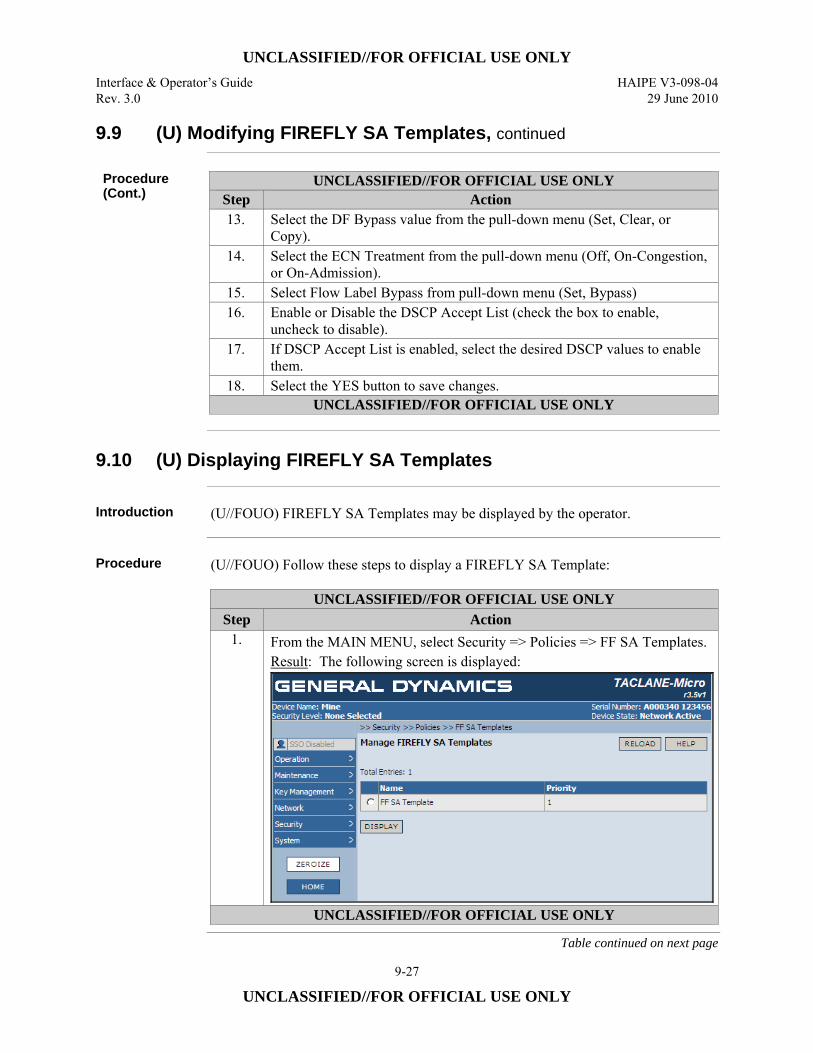
UNCLASSIFIED//FOR OFFICIAL USE ONLY Interface & Operator’s Guide HAIPE V3-098-04 Rev. 3.0 29 June 2010
9-27
UNCLASSIFIED//FOR OFFICIAL USE ONLY
9.9 (U) Modifying FIREFLY SA Templates, continued
Procedure (Cont.)
UNCLASSIFIED//FOR OFFICIAL USE ONLY Step Action 13. Select the DF Bypass value from the pull-down menu (Set, Clear, or
Copy). 14. Select the ECN Treatment from the pull-down menu (Off, On-Congestion,
or On-Admission). 15. Select Flow Label Bypass from pull-down menu (Set, Bypass) 16. Enable or Disable the DSCP Accept List (check the box to enable,
uncheck to disable). 17. If DSCP Accept List is enabled, select the desired DSCP values to enable
them. 18. Select the YES button to save changes.
UNCLASSIFIED//FOR OFFICIAL USE ONLY
9.10 (U) Displaying FIREFLY SA Templates
Introduction (U//FOUO) FIREFLY SA Templates may be displayed by the operator.
Procedure (U//FOUO) Follow these steps to display a FIREFLY SA Template:
UNCLASSIFIED//FOR OFFICIAL USE ONLY Step Action
1. From the MAIN MENU, select Security => Policies => FF SA Templates. Result: The following screen is displayed:
UNCLASSIFIED//FOR OFFICIAL USE ONLY
Table continued on next page

UNCLASSIFIED//FOR OFFICIAL USE ONLY HAIPE V3-098-04 Interface & Operator’s Guide 29 June 2010 Rev. 3.0
9-28
UNCLASSIFIED//FOR OFFICIAL USE ONLY
9.10 (U) Displaying FIREFLY SA Templates, continued
Procedure (Cont.)
UNCLASSIFIED//FOR OFFICIAL USE ONLY Step Action
2. To display an existing FIREFLY SA Template, select the radio button next to the Template name, and then select the DISPLAY button. Result: The following screen is displayed:
UNCLASSIFIED//FOR OFFICIAL USE ONLY
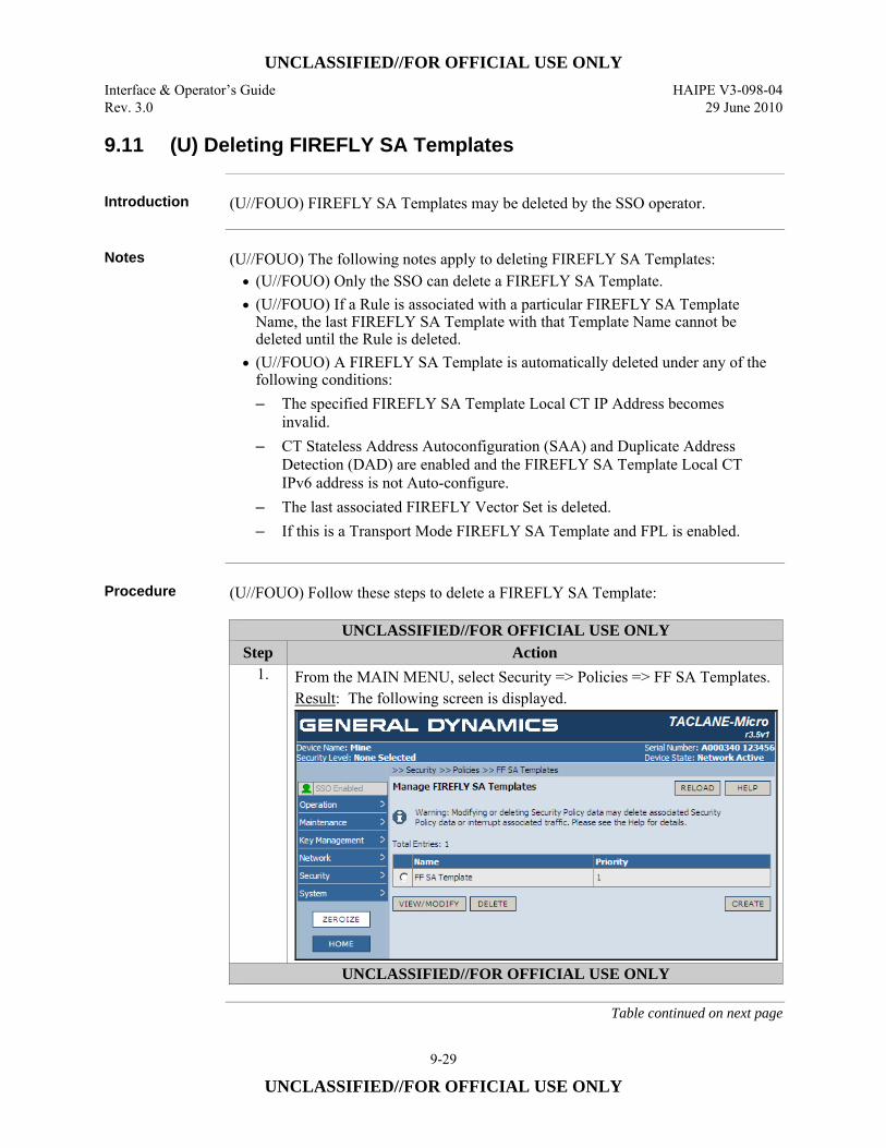
UNCLASSIFIED//FOR OFFICIAL USE ONLY Interface & Operator’s Guide HAIPE V3-098-04 Rev. 3.0 29 June 2010
9-29
UNCLASSIFIED//FOR OFFICIAL USE ONLY
9.11 (U) Deleting FIREFLY SA Templates
Introduction (U//FOUO) FIREFLY SA Templates may be deleted by the SSO operator.
Notes (U//FOUO) The following notes apply to deleting FIREFLY SA Templates:
• (U//FOUO) Only the SSO can delete a FIREFLY SA Template. • (U//FOUO) If a Rule is associated with a particular FIREFLY SA Template
Name, the last FIREFLY SA Template with that Template Name cannot be deleted until the Rule is deleted.
• (U//FOUO) A FIREFLY SA Template is automatically deleted under any of the following conditions: – The specified FIREFLY SA Template Local CT IP Address becomes
invalid. – CT Stateless Address Autoconfiguration (SAA) and Duplicate Address
Detection (DAD) are enabled and the FIREFLY SA Template Local CT IPv6 address is not Auto-configure.
– The last associated FIREFLY Vector Set is deleted. – If this is a Transport Mode FIREFLY SA Template and FPL is enabled.
Procedure (U//FOUO) Follow these steps to delete a FIREFLY SA Template:
UNCLASSIFIED//FOR OFFICIAL USE ONLY Step Action
1. From the MAIN MENU, select Security => Policies => FF SA Templates. Result: The following screen is displayed.
UNCLASSIFIED//FOR OFFICIAL USE ONLY
Table continued on next page
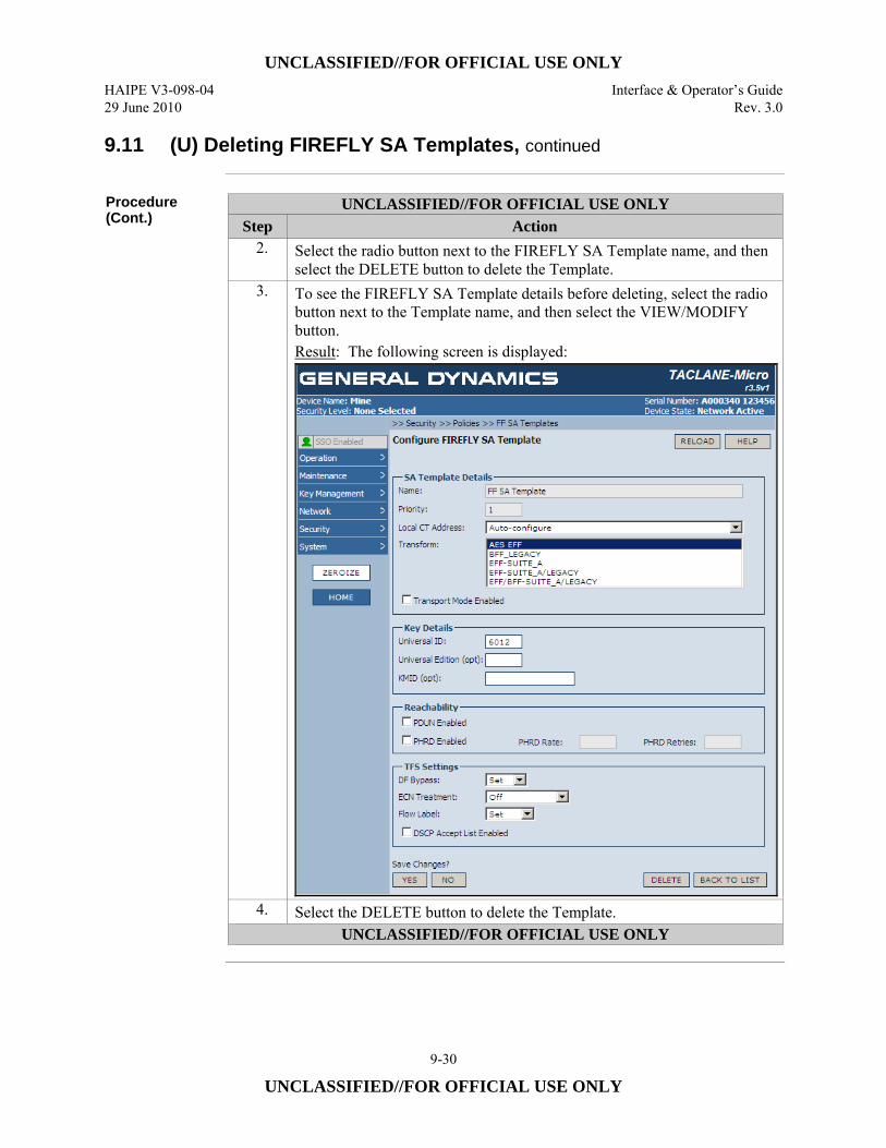
UNCLASSIFIED//FOR OFFICIAL USE ONLY HAIPE V3-098-04 Interface & Operator’s Guide 29 June 2010 Rev. 3.0
9-30
UNCLASSIFIED//FOR OFFICIAL USE ONLY
9.11 (U) Deleting FIREFLY SA Templates, continued
Procedure (Cont.)
UNCLASSIFIED//FOR OFFICIAL USE ONLY Step Action
2. Select the radio button next to the FIREFLY SA Template name, and then select the DELETE button to delete the Template.
3. To see the FIREFLY SA Template details before deleting, select the radio button next to the Template name, and then select the VIEW/MODIFY button. Result: The following screen is displayed:
4. Select the DELETE button to delete the Template. UNCLASSIFIED//FOR OFFICIAL USE ONLY
UNCLASSIFIED//FOR OFFICIAL USE ONLY Interface & Operator’s Guide HAIPE V3-098-04 Rev. 3.0 29 June 2010
9-31
UNCLASSIFIED//FOR OFFICIAL USE ONLY
9.12 (U) Creating Selectors
Introduction (U//FOUO) Selectors are IP traffic filters associated with Rules. The SSO Operator
can create Selectors for use in determining whether or not a particular Rule is a “hit” based on the IP traffic filter defined by the Selector.
Permanent and Default Selectors
(U//FOUO) Refer to Appendix A for a table of Permanent and Default Selectors.
Notes
(U//FOUO) The following notes apply to creating Selectors: • (U//FOUO) Only the SSO can create a Selector. • (U//FOUO) Up to 512 Selectors can be configured. • (U//FOUO) Each Selector must have a unique Selector Name. • (U//FOUO) Multiple Rules can be associated with the same set of Selectors. • (U//FOUO) BYPASS or DISCARD Rules may be associated with Selectors that
include a combination of: – Source Address Range – Destination Address Range – Next Header (Protocol field in IPv4 or Next Header field in IPv6. Since IPv6
datagrams can contain other extension headers, the following IPv6 Next Header values are always skipped when looking for a Next Header value to match against the filter: 0 (Hop-by-Hop Options); 43 (Routing Header); 44 (Fragmentation Header); 60 (Destination Options).
– Next Header Option 1 Range (Source Port Range for TCP/UDP; Type for ICMP)
– Next Header Option 2 Range (Destination Port Range for TCP/UDP; Code for ICMP)
• (U//FOUO) CT OUT PROTECT w/ FIREFLY or w/ PPK Rules, and CT IN PROTECT w/ FIREFLY Rules, may be associated with Selectors that include a combination of: – Source Address Range – Destination Address Range – Next Header = UDP – Next Header Option 1 Range (UDP Source Port Range) = ANY – Next Header Option 2 Range (UDP Destination Port Range = 500 (IKE)
Continued on next page
UNCLASSIFIED//FOR OFFICIAL USE ONLY HAIPE V3-098-04 Interface & Operator’s Guide 29 June 2010 Rev. 3.0
9-32
UNCLASSIFIED//FOR OFFICIAL USE ONLY
9.12 (U) Creating Selectors, continued
Notes (Cont.)
• (U//FOUO) The following apply to the use of OPAQUE and ANY selectors:– ANY means that the particular field of an IP datagram does not need to be
matched by the filter. (The field is a “don’t care”.) – OPAQUE is a subset of ANY, and is only true if the particular field is not
present or not visible for matching. OPAQUE is false if the particular field is present. E.g., a Source Port OPAQUE filter match on the first fragment of a UDP/IP datagram would be false since the Source Port is visible. However, a Source Port OPAQUE filter match on non-first fragments of a UDP/IP datagram would be true since the Source Port is not present.
– If Next Header is ANY, both Next Header Option 1 and Next Header Option 2 must be ANY.
– If Next Header VALUE is not equal to ICMP (1), TCP (6), or UDP (17), both Next Header Option 1 and Next Header Option 2 must be ANY.
• (U//FOUO) Selectors can be created/modified with or without being associated with one or more Rules.
Continued on next page
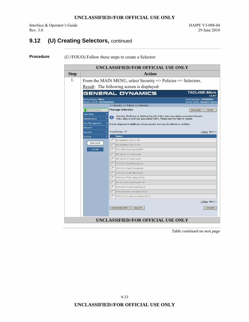
UNCLASSIFIED//FOR OFFICIAL USE ONLY Interface & Operator’s Guide HAIPE V3-098-04 Rev. 3.0 29 June 2010
9-33
UNCLASSIFIED//FOR OFFICIAL USE ONLY
9.12 (U) Creating Selectors, continued
Procedure (U//FOUO) Follow these steps to create a Selector:
UNCLASSIFIED//FOR OFFICIAL USE ONLY Step Action
1. From the MAIN MENU, select Security => Policies => Selectors. Result: The following screen is displayed:
UNCLASSIFIED//FOR OFFICIAL USE ONLY
Table continued on next page
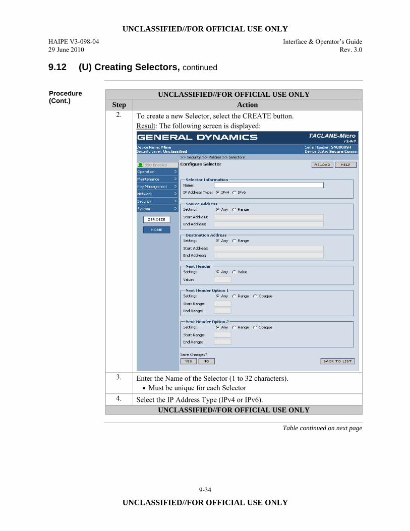
UNCLASSIFIED//FOR OFFICIAL USE ONLY HAIPE V3-098-04 Interface & Operator’s Guide 29 June 2010 Rev. 3.0
9-34
UNCLASSIFIED//FOR OFFICIAL USE ONLY
9.12 (U) Creating Selectors, continued
Procedure (Cont.)
UNCLASSIFIED//FOR OFFICIAL USE ONLY Step Action
2. To create a new Selector, select the CREATE button. Result: The following screen is displayed:
3. Enter the Name of the Selector (1 to 32 characters). • Must be unique for each Selector
4. Select the IP Address Type (IPv4 or IPv6). UNCLASSIFIED//FOR OFFICIAL USE ONLY
Table continued on next page
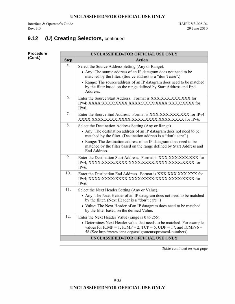
UNCLASSIFIED//FOR OFFICIAL USE ONLY Interface & Operator’s Guide HAIPE V3-098-04 Rev. 3.0 29 June 2010
9-35
UNCLASSIFIED//FOR OFFICIAL USE ONLY
9.12 (U) Creating Selectors, continued
Procedure (Cont.)
UNCLASSIFIED//FOR OFFICIAL USE ONLY Step Action
5. Select the Source Address Setting (Any or Range). • Any: The source address of an IP datagram does not need to be
matched by the filter. (Source address is a “don’t care”.) • Range: The source address of an IP datagram does need to be matched
by the filter based on the range defined by Start Address and End Address.
6. Enter the Source Start Address. Format is XXX.XXX.XXX.XXX for IPv4; XXXX:XXXX:XXXX:XXXX:XXXX:XXXX:XXXX:XXXX for IPv6.
7. Enter the Source End Address. Format is XXX.XXX.XXX.XXX for IPv4; XXXX:XXXX:XXXX:XXXX:XXXX:XXXX:XXXX:XXXX for IPv6.
8. Select the Destination Address Setting (Any or Range). • Any: The destination address of an IP datagram does not need to be
matched by the filter. (Destination address is a “don’t care”.) • Range: The destination address of an IP datagram does need to be
matched by the filter based on the range defined by Start Address and End Address.
9. Enter the Destination Start Address. Format is XXX.XXX.XXX.XXX for IPv4; XXXX:XXXX:XXXX:XXXX:XXXX:XXXX:XXXX:XXXX for IPv6.
10. Enter the Destination End Address. Format is XXX.XXX.XXX.XXX for IPv4; XXXX:XXXX:XXXX:XXXX:XXXX:XXXX:XXXX:XXXX for IPv6.
11. Select the Next Header Setting (Any or Value). • Any: The Next Header of an IP datagram does not need to be matched
by the filter. (Next Header is a “don’t care”.) • Value: The Next Header of an IP datagram does need to be matched
by the filter based on the defined Value. 12. Enter the Next Header Value (range is 0 to 255).
• Determines Next Header value that needs to be matched. For example, values for ICMP = 1, IGMP = 2, TCP = 6, UDP = 17, and ICMPv6 = 58 (See http://www.iana.org/assignments/protocol-numbers).
UNCLASSIFIED//FOR OFFICIAL USE ONLY
Table continued on next page
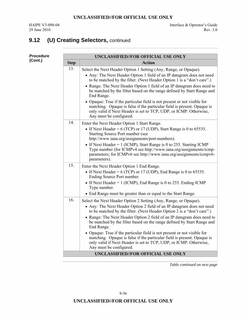
UNCLASSIFIED//FOR OFFICIAL USE ONLY HAIPE V3-098-04 Interface & Operator’s Guide 29 June 2010 Rev. 3.0
9-36
UNCLASSIFIED//FOR OFFICIAL USE ONLY
9.12 (U) Creating Selectors, continued
Procedure (Cont.)
UNCLASSIFIED//FOR OFFICIAL USE ONLY Step Action 13. Select the Next Header Option 1 Setting (Any, Range, or Opaque).
• Any: The Next Header Option 1 field of an IP datagram does not need to be matched by the filter. (Next Header Option 1 is a “don’t care”.)
• Range: The Next Header Option 1 field of an IP datagram does need to be matched by the filter based on the range defined by Start Range and End Range.
• Opaque: True if the particular field is not present or not visible for matching. Opaque is false if the particular field is present. Opaque is only valid if Next Header is set to TCP, UDP, or ICMP. Otherwise, Any must be configured.
14. Enter the Next Header Option 1 Start Range. • If Next Header = 6 (TCP) or 17 (UDP), Start Range is 0 to 65535.
Starting Source Port number (see http://www.iana.org/assignments/port-numbers).
• If Next Header = 1 (ICMP), Start Range is 0 to 255. Starting ICMP Type number (for ICMPv4 see http://www.iana.org/assignments/icmp-parameters; for ICMPv6 see http://www.iana.org/assignments/icmpv6-parameters).
15. Enter the Next Header Option 1 End Range. • If Next Header = 6 (TCP) or 17 (UDP), End Range is 0 to 65535.
Ending Source Port number. • If Next Header = 1 (ICMP), End Range is 0 to 255. Ending ICMP
Type number. • End Range must be greater than or equal to the Start Range.
16. Select the Next Header Option 2 Setting (Any, Range, or Opaque). • Any: The Next Header Option 2 field of an IP datagram does not need
to be matched by the filter. (Next Header Option 2 is a “don’t care”.) • Range: The Next Header Option 2 field of an IP datagram does need to
be matched by the filter based on the range defined by Start Range and End Range.
• Opaque: True if the particular field is not present or not visible for matching. Opaque is false if the particular field is present. Opaque is only valid if Next Header is set to TCP, UDP, or ICMP. Otherwise, Any must be configured.
UNCLASSIFIED//FOR OFFICIAL USE ONLY
Table continued on next page
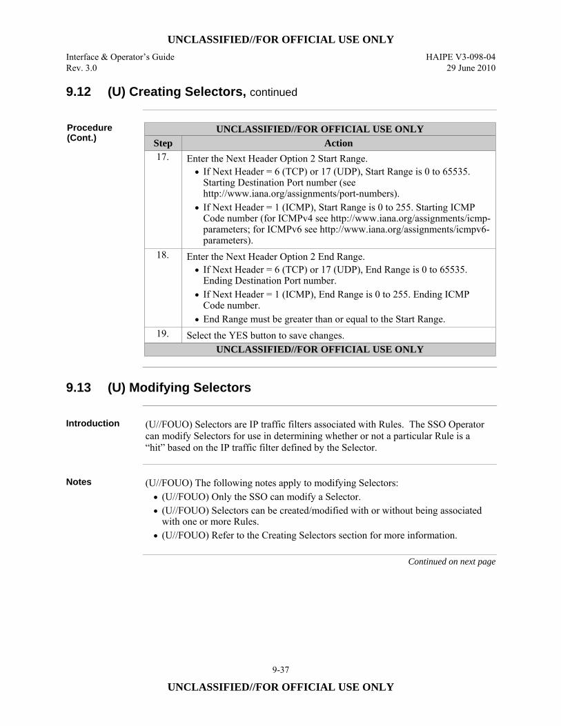
UNCLASSIFIED//FOR OFFICIAL USE ONLY Interface & Operator’s Guide HAIPE V3-098-04 Rev. 3.0 29 June 2010
9-37
UNCLASSIFIED//FOR OFFICIAL USE ONLY
9.12 (U) Creating Selectors, continued
Procedure (Cont.)
UNCLASSIFIED//FOR OFFICIAL USE ONLY Step Action 17. Enter the Next Header Option 2 Start Range.
• If Next Header = 6 (TCP) or 17 (UDP), Start Range is 0 to 65535. Starting Destination Port number (see http://www.iana.org/assignments/port-numbers).
• If Next Header = 1 (ICMP), Start Range is 0 to 255. Starting ICMP Code number (for ICMPv4 see http://www.iana.org/assignments/icmp-parameters; for ICMPv6 see http://www.iana.org/assignments/icmpv6-parameters).
18. Enter the Next Header Option 2 End Range. • If Next Header = 6 (TCP) or 17 (UDP), End Range is 0 to 65535.
Ending Destination Port number. • If Next Header = 1 (ICMP), End Range is 0 to 255. Ending ICMP
Code number. • End Range must be greater than or equal to the Start Range.
19. Select the YES button to save changes. UNCLASSIFIED//FOR OFFICIAL USE ONLY
9.13 (U) Modifying Selectors
Introduction (U//FOUO) Selectors are IP traffic filters associated with Rules. The SSO Operator
can modify Selectors for use in determining whether or not a particular Rule is a “hit” based on the IP traffic filter defined by the Selector.
Notes (U//FOUO) The following notes apply to modifying Selectors:
• (U//FOUO) Only the SSO can modify a Selector. • (U//FOUO) Selectors can be created/modified with or without being associated
with one or more Rules. • (U//FOUO) Refer to the Creating Selectors section for more information.
Continued on next page

UNCLASSIFIED//FOR OFFICIAL USE ONLY HAIPE V3-098-04 Interface & Operator’s Guide 29 June 2010 Rev. 3.0
9-38
UNCLASSIFIED//FOR OFFICIAL USE ONLY
9.13 (U) Modifying Selectors, continued
Procedure (U//FOUO) Follow these steps to modify a Selector:
UNCLASSIFIED//FOR OFFICIAL USE ONLY Step Action 1. From the MAIN MENU, select Security => Policies => Selectors.
Result: The following screen is displayed:
UNCLASSIFIED//FOR OFFICIAL USE ONLY
Table continued on next page
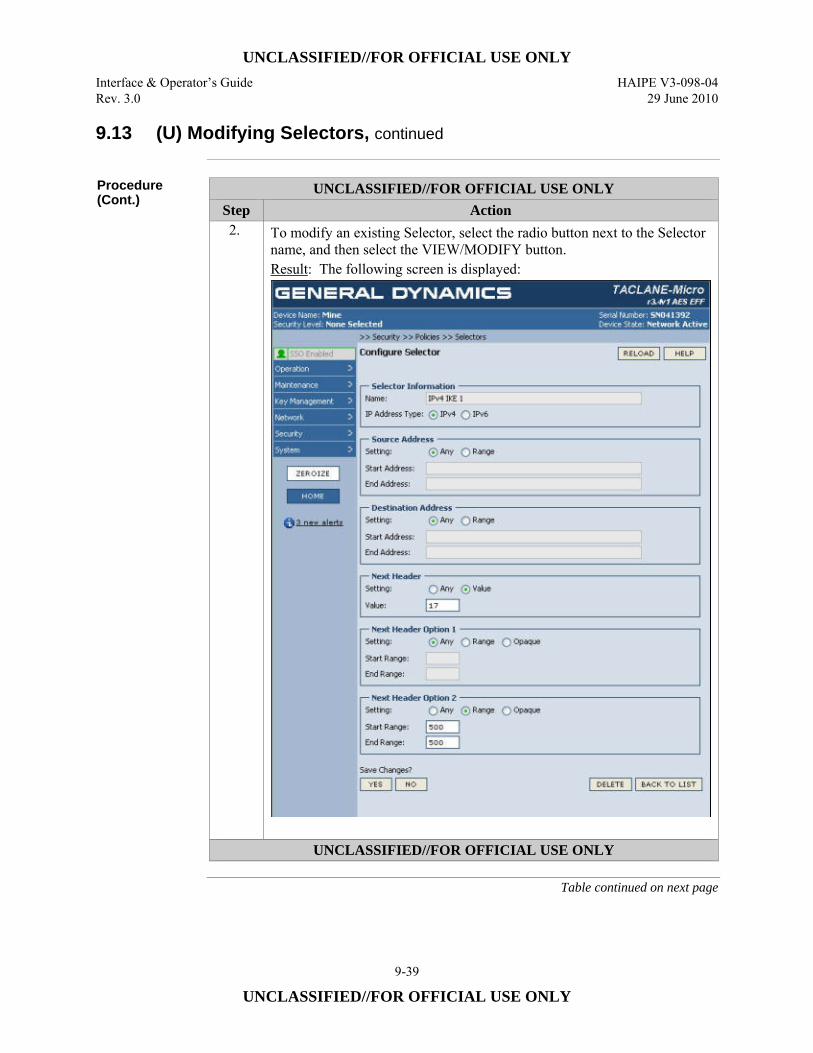
UNCLASSIFIED//FOR OFFICIAL USE ONLY Interface & Operator’s Guide HAIPE V3-098-04 Rev. 3.0 29 June 2010
9-39
UNCLASSIFIED//FOR OFFICIAL USE ONLY
9.13 (U) Modifying Selectors, continued
Procedure (Cont.)
UNCLASSIFIED//FOR OFFICIAL USE ONLY Step Action 2. To modify an existing Selector, select the radio button next to the Selector
name, and then select the VIEW/MODIFY button. Result: The following screen is displayed:
UNCLASSIFIED//FOR OFFICIAL USE ONLY
Table continued on next page
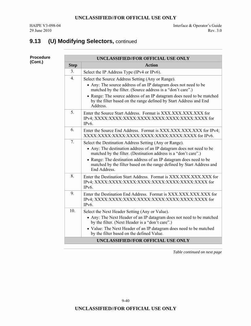
UNCLASSIFIED//FOR OFFICIAL USE ONLY HAIPE V3-098-04 Interface & Operator’s Guide 29 June 2010 Rev. 3.0
9-40
UNCLASSIFIED//FOR OFFICIAL USE ONLY
9.13 (U) Modifying Selectors, continued
Procedure (Cont.)
UNCLASSIFIED//FOR OFFICIAL USE ONLY Step Action 3. Select the IP Address Type (IPv4 or IPv6). 4. Select the Source Address Setting (Any or Range).
• Any: The source address of an IP datagram does not need to be matched by the filter. (Source address is a “don’t care”.)
• Range: The source address of an IP datagram does need to be matched by the filter based on the range defined by Start Address and End Address.
5. Enter the Source Start Address. Format is XXX.XXX.XXX.XXX for IPv4; XXXX:XXXX:XXXX:XXXX:XXXX:XXXX:XXXX:XXXX for IPv6.
6. Enter the Source End Address. Format is XXX.XXX.XXX.XXX for IPv4; XXXX:XXXX:XXXX:XXXX:XXXX:XXXX:XXXX:XXXX for IPv6.
7. Select the Destination Address Setting (Any or Range). • Any: The destination address of an IP datagram does not need to be
matched by the filter. (Destination address is a “don’t care”.) • Range: The destination address of an IP datagram does need to be
matched by the filter based on the range defined by Start Address and End Address.
8. Enter the Destination Start Address. Format is XXX.XXX.XXX.XXX for IPv4; XXXX:XXXX:XXXX:XXXX:XXXX:XXXX:XXXX:XXXX for IPv6.
9. Enter the Destination End Address. Format is XXX.XXX.XXX.XXX for IPv4; XXXX:XXXX:XXXX:XXXX:XXXX:XXXX:XXXX:XXXX for IPv6.
10. Select the Next Header Setting (Any or Value). • Any: The Next Header of an IP datagram does not need to be matched
by the filter. (Next Header is a “don’t care”.) • Value: The Next Header of an IP datagram does need to be matched
by the filter based on the defined Value. UNCLASSIFIED//FOR OFFICIAL USE ONLY
Table continued on next page
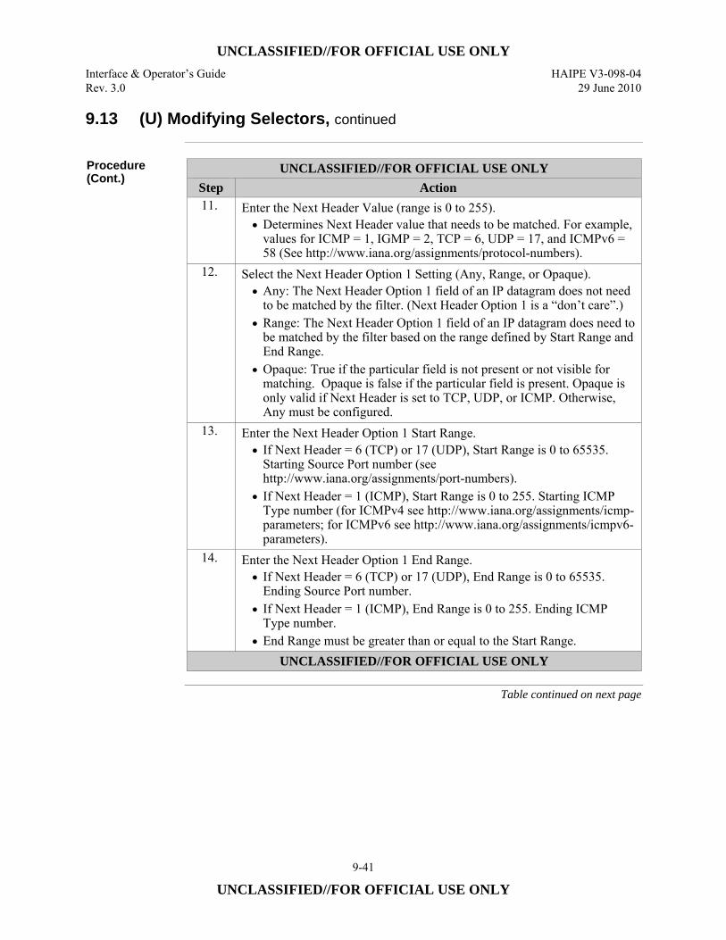
UNCLASSIFIED//FOR OFFICIAL USE ONLY Interface & Operator’s Guide HAIPE V3-098-04 Rev. 3.0 29 June 2010
9-41
UNCLASSIFIED//FOR OFFICIAL USE ONLY
9.13 (U) Modifying Selectors, continued
Procedure (Cont.)
UNCLASSIFIED//FOR OFFICIAL USE ONLY Step Action 11. Enter the Next Header Value (range is 0 to 255).
• Determines Next Header value that needs to be matched. For example, values for ICMP = 1, IGMP = 2, TCP = 6, UDP = 17, and ICMPv6 = 58 (See http://www.iana.org/assignments/protocol-numbers).
12. Select the Next Header Option 1 Setting (Any, Range, or Opaque). • Any: The Next Header Option 1 field of an IP datagram does not need
to be matched by the filter. (Next Header Option 1 is a “don’t care”.) • Range: The Next Header Option 1 field of an IP datagram does need to
be matched by the filter based on the range defined by Start Range and End Range.
• Opaque: True if the particular field is not present or not visible for matching. Opaque is false if the particular field is present. Opaque is only valid if Next Header is set to TCP, UDP, or ICMP. Otherwise, Any must be configured.
13. Enter the Next Header Option 1 Start Range. • If Next Header = 6 (TCP) or 17 (UDP), Start Range is 0 to 65535.
Starting Source Port number (see http://www.iana.org/assignments/port-numbers).
• If Next Header = 1 (ICMP), Start Range is 0 to 255. Starting ICMP Type number (for ICMPv4 see http://www.iana.org/assignments/icmp-parameters; for ICMPv6 see http://www.iana.org/assignments/icmpv6-parameters).
14. Enter the Next Header Option 1 End Range. • If Next Header = 6 (TCP) or 17 (UDP), End Range is 0 to 65535.
Ending Source Port number. • If Next Header = 1 (ICMP), End Range is 0 to 255. Ending ICMP
Type number. • End Range must be greater than or equal to the Start Range.
UNCLASSIFIED//FOR OFFICIAL USE ONLY
Table continued on next page
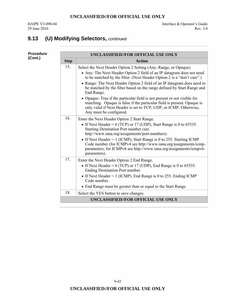
UNCLASSIFIED//FOR OFFICIAL USE ONLY HAIPE V3-098-04 Interface & Operator’s Guide 29 June 2010 Rev. 3.0
9-42
UNCLASSIFIED//FOR OFFICIAL USE ONLY
9.13 (U) Modifying Selectors, continued
Procedure (Cont.)
UNCLASSIFIED//FOR OFFICIAL USE ONLY Step Action 15. Select the Next Header Option 2 Setting (Any, Range, or Opaque).
• Any: The Next Header Option 2 field of an IP datagram does not need to be matched by the filter. (Next Header Option 2 is a “don’t care”.)
• Range: The Next Header Option 2 field of an IP datagram does need to be matched by the filter based on the range defined by Start Range and End Range.
• Opaque: True if the particular field is not present or not visible for matching. Opaque is false if the particular field is present. Opaque is only valid if Next Header is set to TCP, UDP, or ICMP. Otherwise, Any must be configured.
16. Enter the Next Header Option 2 Start Range. • If Next Header = 6 (TCP) or 17 (UDP), Start Range is 0 to 65535.
Starting Destination Port number (see http://www.iana.org/assignments/port-numbers).
• If Next Header = 1 (ICMP), Start Range is 0 to 255. Starting ICMP Code number (for ICMPv4 see http://www.iana.org/assignments/icmp-parameters; for ICMPv6 see http://www.iana.org/assignments/icmpv6-parameters).
17. Enter the Next Header Option 2 End Range. • If Next Header = 6 (TCP) or 17 (UDP), End Range is 0 to 65535.
Ending Destination Port number. • If Next Header = 1 (ICMP), End Range is 0 to 255. Ending ICMP
Code number. • End Range must be greater than or equal to the Start Range.
18. Select the YES button to save changes. UNCLASSIFIED//FOR OFFICIAL USE ONLY
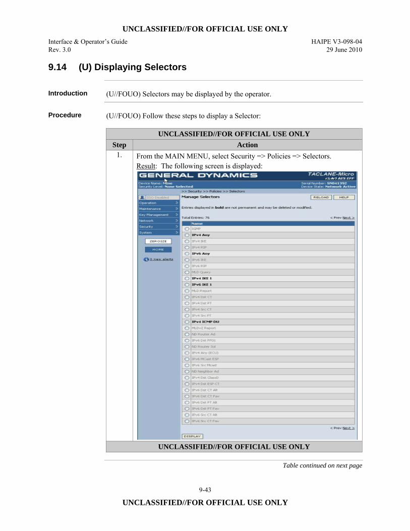
UNCLASSIFIED//FOR OFFICIAL USE ONLY Interface & Operator’s Guide HAIPE V3-098-04 Rev. 3.0 29 June 2010
9-43
UNCLASSIFIED//FOR OFFICIAL USE ONLY
9.14 (U) Displaying Selectors
Introduction (U//FOUO) Selectors may be displayed by the operator.
Procedure (U//FOUO) Follow these steps to display a Selector:
UNCLASSIFIED//FOR OFFICIAL USE ONLY Step Action
1. From the MAIN MENU, select Security => Policies => Selectors. Result: The following screen is displayed:
UNCLASSIFIED//FOR OFFICIAL USE ONLY
Table continued on next page
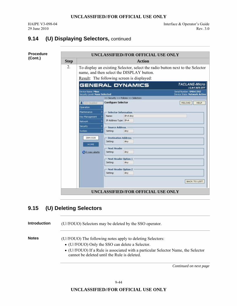
UNCLASSIFIED//FOR OFFICIAL USE ONLY HAIPE V3-098-04 Interface & Operator’s Guide 29 June 2010 Rev. 3.0
9-44
UNCLASSIFIED//FOR OFFICIAL USE ONLY
9.14 (U) Displaying Selectors, continued
Procedure (Cont.)
UNCLASSIFIED//FOR OFFICIAL USE ONLY Step Action
2. To display an existing Selector, select the radio button next to the Selector name, and then select the DISPLAY button. Result: The following screen is displayed:
UNCLASSIFIED//FOR OFFICIAL USE ONLY
9.15 (U) Deleting Selectors
Introduction (U//FOUO) Selectors may be deleted by the SSO operator.
Notes (U//FOUO) The following notes apply to deleting Selectors:
• (U//FOUO) Only the SSO can delete a Selector. • (U//FOUO) If a Rule is associated with a particular Selector Name, the Selector
cannot be deleted until the Rule is deleted.
Continued on next page
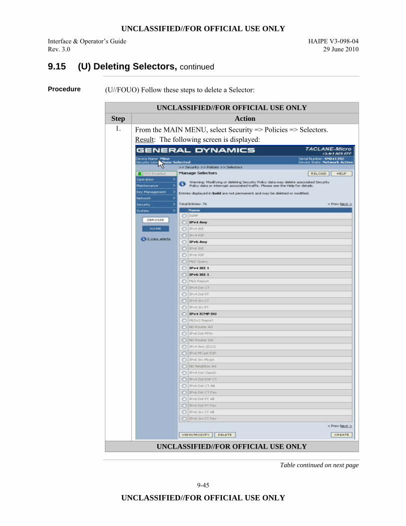
UNCLASSIFIED//FOR OFFICIAL USE ONLY Interface & Operator’s Guide HAIPE V3-098-04 Rev. 3.0 29 June 2010
9-45
UNCLASSIFIED//FOR OFFICIAL USE ONLY
9.15 (U) Deleting Selectors, continued
Procedure (U//FOUO) Follow these steps to delete a Selector:
UNCLASSIFIED//FOR OFFICIAL USE ONLY Step Action
1. From the MAIN MENU, select Security => Policies => Selectors. Result: The following screen is displayed:
UNCLASSIFIED//FOR OFFICIAL USE ONLY
Table continued on next page
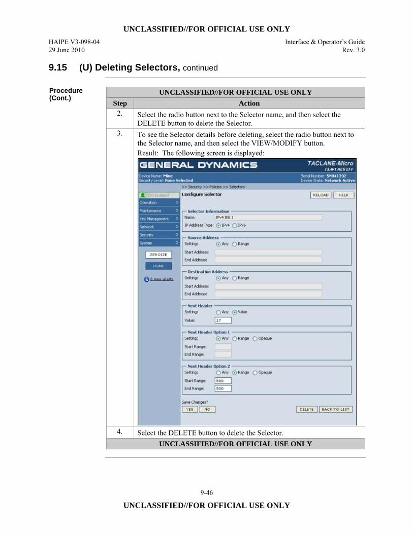
UNCLASSIFIED//FOR OFFICIAL USE ONLY HAIPE V3-098-04 Interface & Operator’s Guide 29 June 2010 Rev. 3.0
9-46
UNCLASSIFIED//FOR OFFICIAL USE ONLY
9.15 (U) Deleting Selectors, continued
Procedure (Cont.)
UNCLASSIFIED//FOR OFFICIAL USE ONLY Step Action
2. Select the radio button next to the Selector name, and then select the DELETE button to delete the Selector.
3. To see the Selector details before deleting, select the radio button next to the Selector name, and then select the VIEW/MODIFY button. Result: The following screen is displayed:
4. Select the DELETE button to delete the Selector. UNCLASSIFIED//FOR OFFICIAL USE ONLY
UNCLASSIFIED//FOR OFFICIAL USE ONLY Interface & Operator’s Guide HAIPE V3-098-04 Rev. 3.0 29 June 2010
9-47
UNCLASSIFIED//FOR OFFICIAL USE ONLY
9.16 (U) Creating Rules
Introduction (U//FOUO) The SSO Operator can create Rules to BYPASS, DISCARD, or
PROTECT IP traffic.
Permanent and Default Rules
(U//FOUO) Refer to Appendix A for a table of Permanent and Default Rules.
Notes (U//FOUO) The following notes apply to creating Rules:
• (U//FOUO) Only the SSO can create Rules. • (U//FOUO) Up to 512 Rules are supported. In addition to user-defined Rules,
this number includes: – Permanent Rules: Rules needed to support mandatory security policy or
essential TACLANE IP traffic paths. Permanent Rules cannot be modified or deleted.
– Default Rules: Rules needed to support user traffic or optional TACLANE IP traffic paths. Default Rules can be modified or deleted.
– Expanded Rules: One user-defined Rule may need to be represented as multiple Rules in the SPD.
• (U//FOUO) Each Rule must have a unique combination of the following fields: – Priority – Interface – Direction
• (U//FOUO) BYPASS or DISCARD Rules may be associated with Selectors that include a combination of: – Source Address Range – Destination Address Range – Next Header (Protocol field in IPv4 or Next Header field in IPv6) – Next Header Option 1 Range (Source Port Range for TCP/UDP; Type for
ICMP) – Next Header Option 2 Range (Destination Port Range for TCP/UDP; Code
for ICMP)
Continued on next page
UNCLASSIFIED//FOR OFFICIAL USE ONLY HAIPE V3-098-04 Interface & Operator’s Guide 29 June 2010 Rev. 3.0
9-48
UNCLASSIFIED//FOR OFFICIAL USE ONLY
9.16 (U) Creating Rules, continued
Notes (Cont.) • (U//FOUO) CT OUT PROTECT w/ FIREFLY or w/ PPK Rules, and CT IN
PROTECT w/ FIREFLY Rules, may be associated with Selectors that include a combination of: – Source Address Range – Destination Address Range – Next Header = UDP – Next Header Option 1 Range (UDP Source Port Range) = ANY – Next Header Option 2 Range (UDP Destination Port Range = 500 (IKE))
• For all Rules, a Selector with the desired Selector Name must be configured before creating a Rule.
• For PROTECT w/ FIREFLY Rules, a FIREFLY SA Template with the desired FIREFLY SA Template Name (entered in the FF SA Template/PPK Chain ID field) must be configured before creating the Rule.
• For PROTECT w/ FIREFLY Rules, the total number of Transforms linked to all associated FIREFLY SA Templates must be less than or equal to 13.
• For PROTECT w/ PPK Rules, if the PPK Chain ID (entered in the FF SA Template/PPK Chain ID field) is not blank, the PPK Chain must exist before creating the Rule.
• Selectors can be created/modified with or without being associated with one or more Rules.
• Multiple FIREFLY SAs can be established to different peer HAIPEs that are a “hit” for the same PROTECT w/ FIREFLY Rule.
• A PROTECT w/ PPK Rule can be a “hit” for multiple PPK SAs established to different peer HAIPEs.
• Only one SA (FIREFLY or PPK) per IP version may exist at any given time to any given peer HAIPE.
• When a PROTECT w/ FIREFLY Rule and/or the associated Selector is modified, all FIREFLY SAs created using that Rule are deleted. (FIREFLY SAs are re-established based on subsequent IP traffic that is a “hit” on the modified Rule.)
• When a PROTECT w/ PPK Rule and/or the associated Selector is modified, the Rule is disassociated from all PPK SAs. (The Rule is reassociated with PPK SAs based on subsequent IP traffic that is a “hit” on the modified Rule.)
Continued on next page
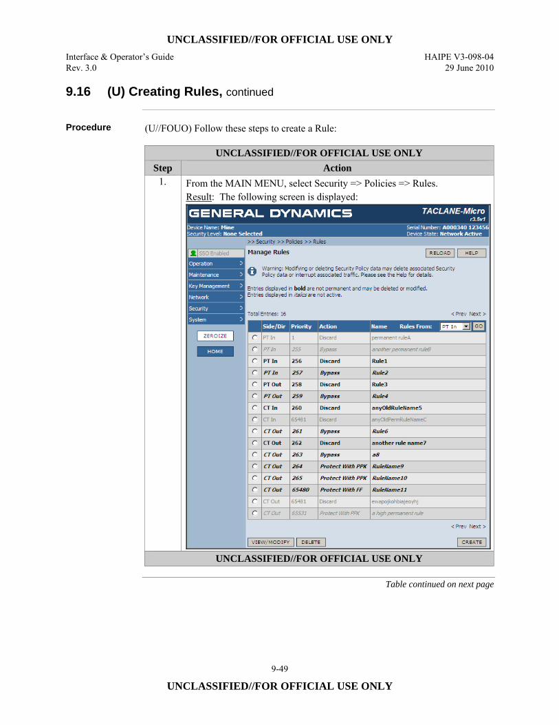
UNCLASSIFIED//FOR OFFICIAL USE ONLY Interface & Operator’s Guide HAIPE V3-098-04 Rev. 3.0 29 June 2010
9-49
UNCLASSIFIED//FOR OFFICIAL USE ONLY
9.16 (U) Creating Rules, continued
Procedure (U//FOUO) Follow these steps to create a Rule:
UNCLASSIFIED//FOR OFFICIAL USE ONLY Step Action
1. From the MAIN MENU, select Security => Policies => Rules. Result: The following screen is displayed:
UNCLASSIFIED//FOR OFFICIAL USE ONLY
Table continued on next page

UNCLASSIFIED//FOR OFFICIAL USE ONLY HAIPE V3-098-04 Interface & Operator’s Guide 29 June 2010 Rev. 3.0
9-50
UNCLASSIFIED//FOR OFFICIAL USE ONLY
9.16 (U) Creating Rules, continued
Procedure (Cont.)
UNCLASSIFIED//FOR OFFICIAL USE ONLY Step Action
2. To create a new Rule, select the CREATE button. Result: The following screen is displayed:
3. Enable or Disable Rule (check the box to enable, uncheck to disable). 4. Enter the Name of the Rule (1 to 32 characters). 5. Enter the Priority of the Rule (range is 256 to 65280; values outside of this
range are reserved for Permanent Rules). 6. Select the Side/Direction from the pull-down menu (PT IN, PT OUT, CT
IN, or CT OUT). • The combination of Priority, Side (Interface), and Direction must be
unique for each Rule. 7. Select the Selector to associate with this Rule from the scrolled list. 8. Select the Action from the pull-down menu (Bypass, Discard, Protect with
FF, or Protect with PPK). UNCLASSIFIED//FOR OFFICIAL USE ONLY
Table continued on next page
UNCLASSIFIED//FOR OFFICIAL USE ONLY Interface & Operator’s Guide HAIPE V3-098-04 Rev. 3.0 29 June 2010
9-51
UNCLASSIFIED//FOR OFFICIAL USE ONLY
9.16 (U) Creating Rules, continued
Procedure (Cont.)
UNCLASSIFIED//FOR OFFICIAL USE ONLY Step Action
9. Select the FF SA Template/PPK Chain ID from the scrolled list. For: • Bypass or Discard Rules, this field is left blank. • Protect w/ FF Rules, this field identifies the set of FIREFLY SA
Templates associated with the Rule by FIREFLY SA Template Name. • Protect w/ PPK Rules, this field can be left Auto-select
(recommended) – in which case any established PPK SA associated with the peer HAIPE is used to protect the traffic that “hits” the Rule – or can optionally identify the PPK Chain ID of the PPK Chain to use to protect the traffic. In the latter case, only a PPK SA with the peer HAIPE using the specified PPK Chain ID is used.
10. Select the YES button to save changes. UNCLASSIFIED//FOR OFFICIAL USE ONLY
9.17 (U) Modifying Rules
Introduction (U//FOUO) The SSO Operator can modify Rules to BYPASS, DISCARD, or
PROTECT IP traffic.
Notes (U//FOUO) The following notes apply to modifying Rules:
• Only the SSO can modify a Rule. • Refer to the Creating Rules section for more information.
Continued on next page

UNCLASSIFIED//FOR OFFICIAL USE ONLY HAIPE V3-098-04 Interface & Operator’s Guide 29 June 2010 Rev. 3.0
9-52
UNCLASSIFIED//FOR OFFICIAL USE ONLY
9.17 (U) Modifying Rules, continued
Procedure (U//FOUO) Follow these steps to modify a Rule:
UNCLASSIFIED//FOR OFFICIAL USE ONLY Step Action
1. From the MAIN MENU, select Security => Policies => Rules. Result: The following screen is displayed:
UNCLASSIFIED//FOR OFFICIAL USE ONLY
Table continued on next page
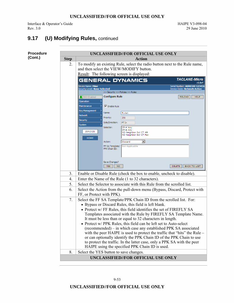
UNCLASSIFIED//FOR OFFICIAL USE ONLY Interface & Operator’s Guide HAIPE V3-098-04 Rev. 3.0 29 June 2010
9-53
UNCLASSIFIED//FOR OFFICIAL USE ONLY
9.17 (U) Modifying Rules, continued
Procedure (Cont.)
UNCLASSIFIED//FOR OFFICIAL USE ONLY Step Action
2. To modify an existing Rule, select the radio button next to the Rule name, and then select the VIEW/MODIFY button. Result: The following screen is displayed:
3. Enable or Disable Rule (check the box to enable, uncheck to disable). 4. Enter the Name of the Rule (1 to 32 characters). 5. Select the Selector to associate with this Rule from the scrolled list. 6. Select the Action from the pull-down menu (Bypass, Discard, Protect with
FF, or Protect with PPK). 7. Select the FF SA Template/PPK Chain ID from the scrolled list. For:
• Bypass or Discard Rules, this field is left blank. • Protect w/ FF Rules, this field identifies the set of FIREFLY SA
Templates associated with the Rule by FIREFLY SA Template Name. It must be less than or equal to 32 characters in length.
• Protect w/ PPK Rules, this field can be left set to Auto-select (recommended) – in which case any established PPK SA associated with the peer HAIPE is used to protect the traffic that “hits” the Rule – or can optionally identify the PPK Chain ID of the PPK Chain to use to protect the traffic. In the latter case, only a PPK SA with the peer HAIPE using the specified PPK Chain ID is used.
8. Select the YES button to save changes. UNCLASSIFIED//FOR OFFICIAL USE ONLY
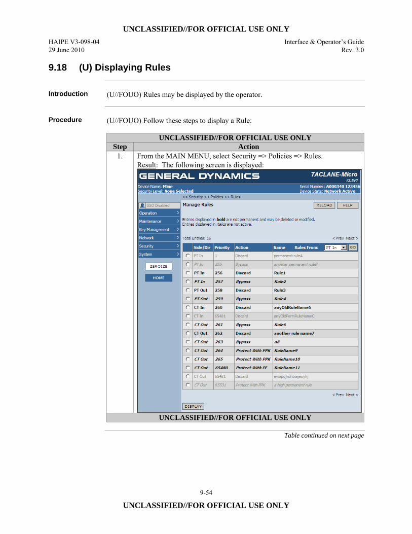
UNCLASSIFIED//FOR OFFICIAL USE ONLY HAIPE V3-098-04 Interface & Operator’s Guide 29 June 2010 Rev. 3.0
9-54
UNCLASSIFIED//FOR OFFICIAL USE ONLY
9.18 (U) Displaying Rules
Introduction (U//FOUO) Rules may be displayed by the operator.
Procedure (U//FOUO) Follow these steps to display a Rule:
UNCLASSIFIED//FOR OFFICIAL USE ONLY Step Action
1. From the MAIN MENU, select Security => Policies => Rules. Result: The following screen is displayed:
UNCLASSIFIED//FOR OFFICIAL USE ONLY
Table continued on next page

UNCLASSIFIED//FOR OFFICIAL USE ONLY Interface & Operator’s Guide HAIPE V3-098-04 Rev. 3.0 29 June 2010
9-55
UNCLASSIFIED//FOR OFFICIAL USE ONLY
9.18 (U) Displaying Rules, continued
Procedure (Cont.)
UNCLASSIFIED//FOR OFFICIAL USE ONLY Step Action
2. To display an existing Rule, select the radio button next to the Rule name, and then select the DISPLAY button. Result: The following screen is displayed:
UNCLASSIFIED//FOR OFFICIAL USE ONLY
9.19 (U) Deleting Rules
Introduction (U//FOUO) Rules may be deleted by the SSO operator.
Notes (U//FOUO) The following notes apply to deleting Rules:
• (U//FOUO) Only the SSO operator can delete a Rule. • (U//FOUO) A PROTECT Rule is automatically deleted if it is configured for
PROTECT w/ PPK, and the PPK/FF TEMP field specifies a PPK Chain ID that has been deleted (is not Auto-select).
Continued on next page

UNCLASSIFIED//FOR OFFICIAL USE ONLY HAIPE V3-098-04 Interface & Operator’s Guide 29 June 2010 Rev. 3.0
9-56
UNCLASSIFIED//FOR OFFICIAL USE ONLY
9.19 (U) Deleting Rules, continued
Procedure (U//FOUO) Follow these steps to delete a Rule:
UNCLASSIFIED//FOR OFFICIAL USE ONLY Step Action
1. From the MAIN MENU, select Security => Policies => Rules. Result: The following screen is displayed:
UNCLASSIFIED//FOR OFFICIAL USE ONLY
Table continued on next page
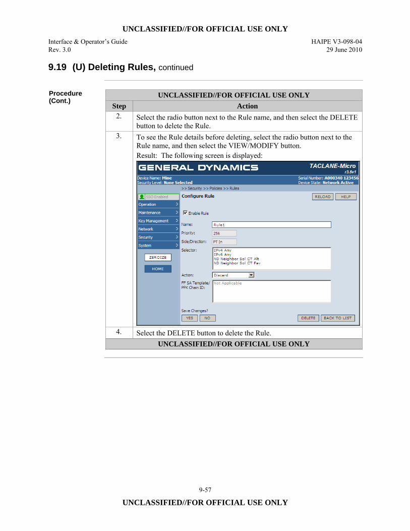
UNCLASSIFIED//FOR OFFICIAL USE ONLY Interface & Operator’s Guide HAIPE V3-098-04 Rev. 3.0 29 June 2010
9-57
UNCLASSIFIED//FOR OFFICIAL USE ONLY
9.19 (U) Deleting Rules, continued
Procedure (Cont.)
UNCLASSIFIED//FOR OFFICIAL USE ONLY Step Action
2. Select the radio button next to the Rule name, and then select the DELETE button to delete the Rule.
3. To see the Rule details before deleting, select the radio button next to the Rule name, and then select the VIEW/MODIFY button. Result: The following screen is displayed:
4. Select the DELETE button to delete the Rule. UNCLASSIFIED//FOR OFFICIAL USE ONLY

UNCLASSIFIED//FOR OFFICIAL USE ONLY HAIPE V3-098-04 Interface & Operator’s Guide 29 June 2010 Rev. 3.0
9-58
UNCLASSIFIED//FOR OFFICIAL USE ONLY
(U) This page intentionally left blank.
UNCLASSIFIED//FOR OFFICIAL USE ONLY Interface & Operator’s Guide HAIPE V3-098-04 Rev. 3.0 29 June 2010
10-1
UNCLASSIFIED//FOR OFFICIAL USE ONLY
10.0 (U) CONFIGURING/MANAGING SECURITY ASSOCIATIONS
10.1 (U) Entering Secure Communications State
Introduction (U//FOUO) The operator may enter Secure Communications state to process all user
and management traffic.
Automated Peer TACLANE Discovery
(U//FOUO) TACLANEs support automated peer TACLANE discovery for SAs, through the HAIPE IS Secure Dynamic Discovery (SDD) protocol, as described in HAIPE IS v3 Legacy Discovery Extension. Once a peer TACLANE is identified, the following occurs: • (U//FOUO) Existing PPK Security Associations are checked for a match based
on the remote TACLANE IP address. If a match is found, the corresponding Security Association is used to secure the IP traffic.
• (U//FOUO) Existing Security Associations using FIREFLY TEKs are checked for a match based on the remote TACLANE IP address. If a match is found, the corresponding Security Association is used to secure the IP traffic.
(U//FOUO) If there is no matching Security Association, and an operational FIREFLY vector set is usable at the current security level, the following occurs: a new Security Association is created and the initiator and responder peer TACLANEs cooperatively generate a FIREFLY TEK using their FIREFLY vector sets.
Remote TACLANE Static Routes
(U//FOUO) If automated peer TACLANE discovery is not desirable, manual entries can be placed within the Remote Enclave/Peer Enclave Table. This eliminates the need for automated peer TACLANE discovery. (See the section “Configuring Routes”). When manual entries are present within the Remote Enclave/Peer Enclave Table, PPK and FIREFLY can both be used to secure communications without the use of automated peer TACLANE discovery.
Continued on next page
UNCLASSIFIED//FOR OFFICIAL USE ONLY HAIPE V3-098-04 Interface & Operator’s Guide 29 June 2010 Rev. 3.0
10-2
UNCLASSIFIED//FOR OFFICIAL USE ONLY
10.1 (U) Entering Secure Communications State, continued
Securing Multicast Traffic
(U//FOUO) TACLANEs support static multicast. • (U//FOUO) A static multicast group is configured on the TACLANE by
establishing a Remote Enclave/Peer Enclave Table entry and Security Association Database entry for the static multicast group address.
• (U//FOUO) Security Association to Remote TACLANE IP addresses that are a mix of multicast and unicast IP addresses may be assigned to the same PPK.
• (U//FOUO) TACLANE will encrypt all PT IP datagram traffic destined for the specified multicast (Class D) IP address and send the CT ESP IP datagrams to the multicast address indicated in the Remote Enclave/Peer Enclave Table entry and the Security Association Database entry.
• (U//FOUO) Received CT ESP IP datagrams destined for the specified multicast IP address in the Security Association Database entry are decrypted, and the PT IP datagrams are sent to the multicast address indicated in the PT IP header.
• (U//FOUO) Multicast IP datagram traffic is not supported for FIREFLY.
Notes (U//FOUO) The following notes apply to entering Secure Communications:
• (U//FOUO) TACLANE must be in the Network Active state, with a security level selected, in order to enter Secure Communications state.
• (U//FOUO) All communicating TACLANEs must be at the same security level. • (U//FOUO) If FIREFLY TEKs are used, each communicating TACLANE must
have a unique valid operational FIREFLY vector set, and the FIREFLY vector sets must be valid for the current security level.
• (U//FOUO) If PPKs are used, all communicating TACLANEs must have the same valid PPK loaded, at the same security level, with the same effective date.
• (U//FOUO) Transitioning to Secure Communications is prohibited after a successful Change Signature Command until a new software image is successfully installed.
Continued on next page
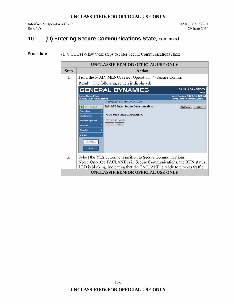
UNCLASSIFIED//FOR OFFICIAL USE ONLY Interface & Operator’s Guide HAIPE V3-098-04 Rev. 3.0 29 June 2010
10-3
UNCLASSIFIED//FOR OFFICIAL USE ONLY
10.1 (U) Entering Secure Communications State, continued
Procedure (U//FOUO) Follow these steps to enter Secure Communications state:
UNCLASSIFIED//FOR OFFICIAL USE ONLY Step Action
1. From the MAIN MENU, select Operation => Secure Comm. Result: The following screen is displayed:
2. Select the YES button to transition to Secure Communications. Note: Once the TACLANE is in Secure Communications, the RUN status LED is blinking, indicating that the TACLANE is ready to process traffic.
UNCLASSIFIED//FOR OFFICIAL USE ONLY
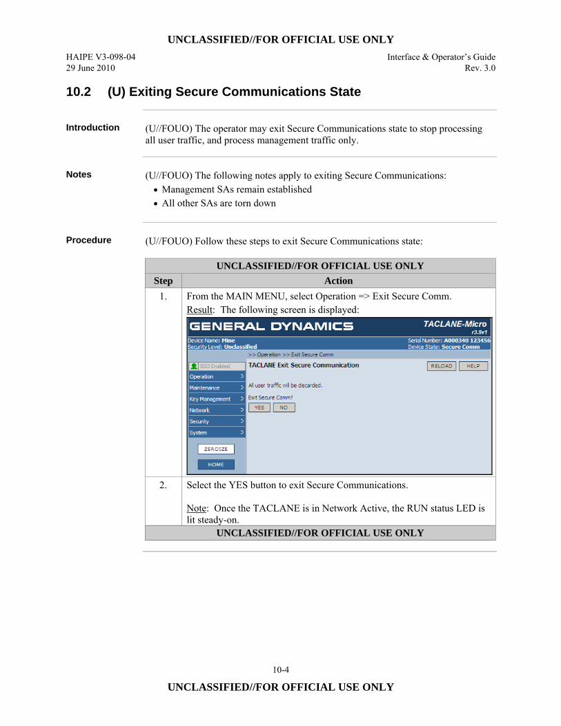
UNCLASSIFIED//FOR OFFICIAL USE ONLY HAIPE V3-098-04 Interface & Operator’s Guide 29 June 2010 Rev. 3.0
10-4
UNCLASSIFIED//FOR OFFICIAL USE ONLY
10.2 (U) Exiting Secure Communications State
Introduction (U//FOUO) The operator may exit Secure Communications state to stop processing
all user traffic, and process management traffic only.
Notes (U//FOUO) The following notes apply to exiting Secure Communications:
• Management SAs remain established • All other SAs are torn down
Procedure (U//FOUO) Follow these steps to exit Secure Communications state:
UNCLASSIFIED//FOR OFFICIAL USE ONLY Step Action
1. From the MAIN MENU, select Operation => Exit Secure Comm. Result: The following screen is displayed:
2. Select the YES button to exit Secure Communications. Note: Once the TACLANE is in Network Active, the RUN status LED is lit steady-on.
UNCLASSIFIED//FOR OFFICIAL USE ONLY

UNCLASSIFIED//FOR OFFICIAL USE ONLY Interface & Operator’s Guide HAIPE V3-098-04 Rev. 3.0 29 June 2010
10-5
UNCLASSIFIED//FOR OFFICIAL USE ONLY
10.3 (U) Displaying Security Association Info
Introduction (U//FOUO) The operator may view Security Associations (SAs) while in Network
Active or Secure Communications state.
Notes (U//FOUO) The following notes apply to the “Remote CTs:” navigation tool on the
Manage Established SAs screen: • (U//FOUO) The CT IP address entered in the navigation tool must be the same
version as the selected IP version (IPv4 or IPv6). • (U//FOUO) The CT IP address entered must be a complete address. • (U//FOUO) Select the GO button to display the SA list starting with the entered
Remote INE CT IP address. • (U//FOUO) Up to 32 entries are displayed on a screen, from the beginning of the
SA list or from the remote CT IP address entered in the navigation tool. • (U//FOUO) Selecting the RELOAD button restores the table view, beginning
with the first page of the table.
Procedure (U//FOUO) Follow these steps to display SA information:
UNCLASSIFIED//FOR OFFICIAL USE ONLY Step Action
1. From the MAIN MENU, select Operation => SA Info. Result: The following screen is displayed:
Note: The full CT IP address of the first remote INE in the SA List is displayed in the “Remote CTs:” entry box.
UNCLASSIFIED//FOR OFFICIAL USE ONLY
Table continued on next page
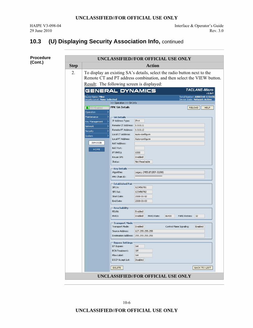
UNCLASSIFIED//FOR OFFICIAL USE ONLY HAIPE V3-098-04 Interface & Operator’s Guide 29 June 2010 Rev. 3.0
10-6
UNCLASSIFIED//FOR OFFICIAL USE ONLY
10.3 (U) Displaying Security Association Info, continued
Procedure (Cont.)
UNCLASSIFIED//FOR OFFICIAL USE ONLY Step Action
2. To display an existing SA’s details, select the radio button next to the Remote CT and PT address combination, and then select the VIEW button. Result: The following screen is displayed:
UNCLASSIFIED//FOR OFFICIAL USE ONLY
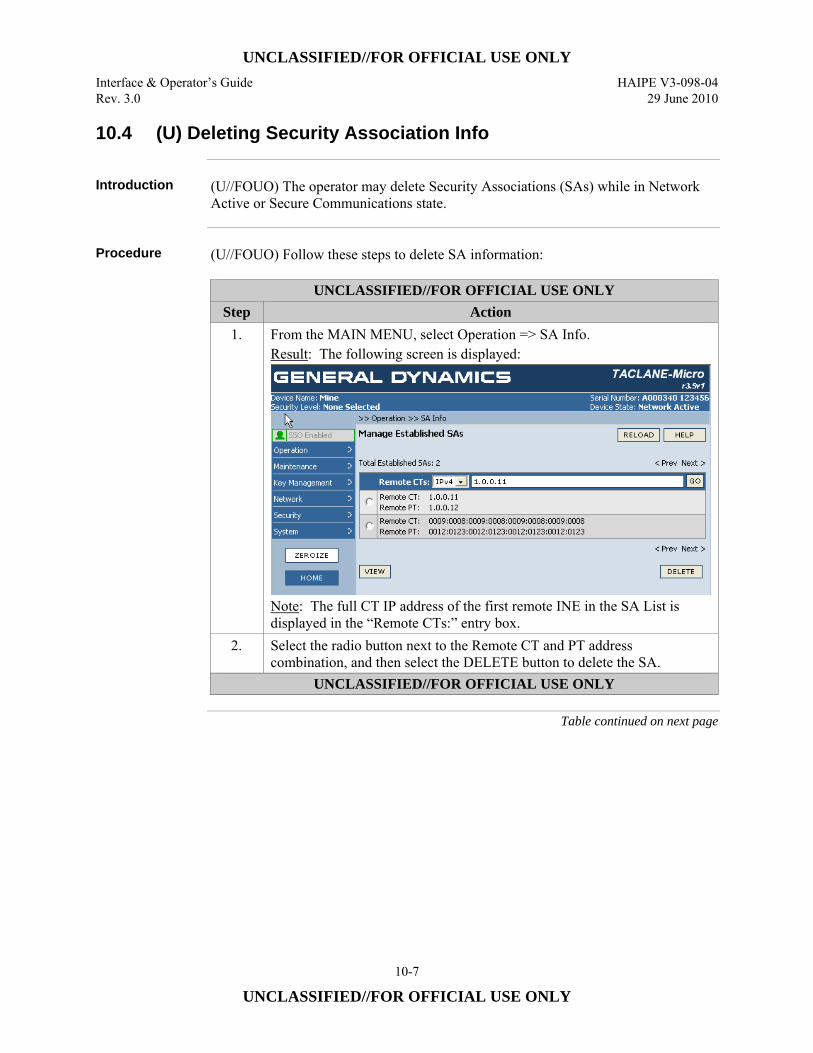
UNCLASSIFIED//FOR OFFICIAL USE ONLY Interface & Operator’s Guide HAIPE V3-098-04 Rev. 3.0 29 June 2010
10-7
UNCLASSIFIED//FOR OFFICIAL USE ONLY
10.4 (U) Deleting Security Association Info
Introduction (U//FOUO) The operator may delete Security Associations (SAs) while in Network
Active or Secure Communications state.
Procedure (U//FOUO) Follow these steps to delete SA information:
UNCLASSIFIED//FOR OFFICIAL USE ONLY Step Action
1. From the MAIN MENU, select Operation => SA Info. Result: The following screen is displayed:
Note: The full CT IP address of the first remote INE in the SA List is displayed in the “Remote CTs:” entry box.
2. Select the radio button next to the Remote CT and PT address combination, and then select the DELETE button to delete the SA.
UNCLASSIFIED//FOR OFFICIAL USE ONLY
Table continued on next page
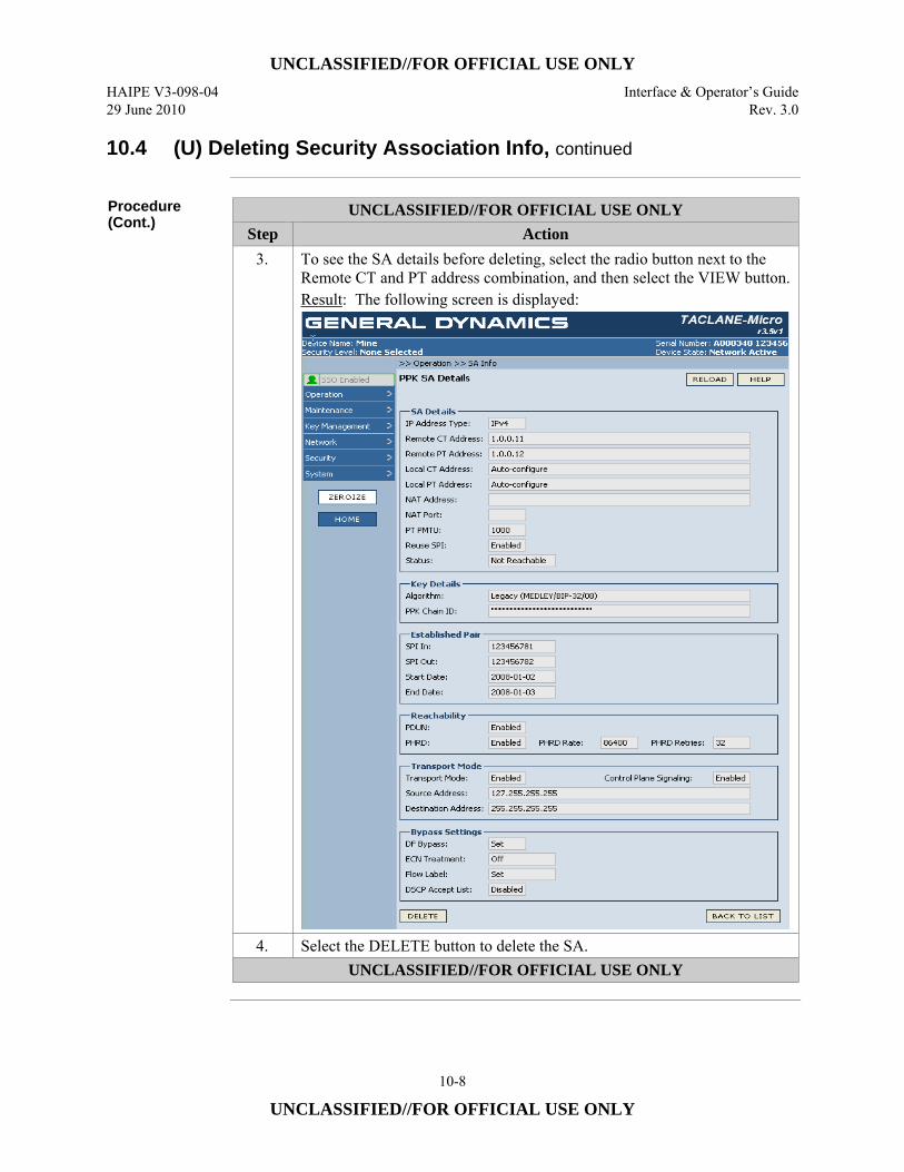
UNCLASSIFIED//FOR OFFICIAL USE ONLY HAIPE V3-098-04 Interface & Operator’s Guide 29 June 2010 Rev. 3.0
10-8
UNCLASSIFIED//FOR OFFICIAL USE ONLY
10.4 (U) Deleting Security Association Info, continued
Procedure (Cont.)
UNCLASSIFIED//FOR OFFICIAL USE ONLY Step Action
3. To see the SA details before deleting, select the radio button next to the Remote CT and PT address combination, and then select the VIEW button. Result: The following screen is displayed:
4. Select the DELETE button to delete the SA. UNCLASSIFIED//FOR OFFICIAL USE ONLY
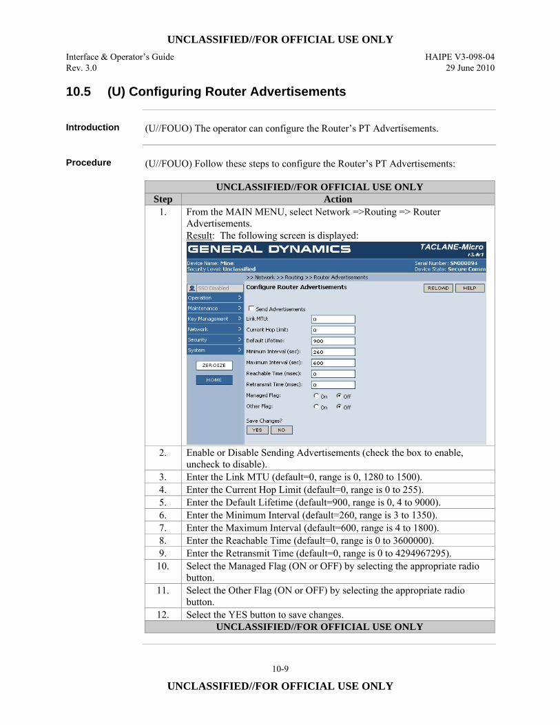
UNCLASSIFIED//FOR OFFICIAL USE ONLY Interface & Operator’s Guide HAIPE V3-098-04 Rev. 3.0 29 June 2010
10-9
UNCLASSIFIED//FOR OFFICIAL USE ONLY
10.5 (U) Configuring Router Advertisements
Introduction (U//FOUO) The operator can configure the Router’s PT Advertisements.
Procedure (U//FOUO) Follow these steps to configure the Router’s PT Advertisements:
UNCLASSIFIED//FOR OFFICIAL USE ONLY Step Action
1. From the MAIN MENU, select Network =>Routing => Router Advertisements. Result: The following screen is displayed:
2. Enable or Disable Sending Advertisements (check the box to enable, uncheck to disable).
3. Enter the Link MTU (default=0, range is 0, 1280 to 1500). 4. Enter the Current Hop Limit (default=0, range is 0 to 255). 5. Enter the Default Lifetime (default=900, range is 0, 4 to 9000). 6. Enter the Minimum Interval (default=260, range is 3 to 1350). 7. Enter the Maximum Interval (default=600, range is 4 to 1800). 8. Enter the Reachable Time (default=0, range is 0 to 3600000). 9. Enter the Retransmit Time (default=0, range is 0 to 4294967295).
10. Select the Managed Flag (ON or OFF) by selecting the appropriate radio button.
11. Select the Other Flag (ON or OFF) by selecting the appropriate radio button.
12. Select the YES button to save changes. UNCLASSIFIED//FOR OFFICIAL USE ONLY
UNCLASSIFIED//FOR OFFICIAL USE ONLY HAIPE V3-098-04 Interface & Operator’s Guide 29 June 2010 Rev. 3.0
10-10
UNCLASSIFIED//FOR OFFICIAL USE ONLY
10.6 (U) Creating Remote TACLANE Routes
Introduction (U//FOUO) The Remote Enclave/Peer Enclave Table provides a list of PT IP
addresses/prefixes to HAIPE relationships. Entries in the table may be made automatically, through Secure Dynamic Discovery (SDD), through Generic Discovery Client (GDC), IM-PEPD, Topology Payloads, or through manual methods (static routes). The Discovery process can populate information in the Remote Enclave/Peer Enclave Table that detail relationships between remote PT IP addresses/prefixes and remote ECUs. Manual entries in the Remote Enclave/Peer Enclave Table cover remote PT IP address/prefix to ECU relationships. (U//FOUO) The TACLANE operator can define static routes which associate destination IP network identifiers with remote TACLANEs protecting that target. More basically, a static route answers the following question: to which TACLANE should the SA be established for communications to this remote network or target? (U//FOUO) In addition to defining remote TACLANE static routes for particular IP network addresses, the TACLANE operator can also define one default static route (to a remote TACLANE).
Remote Enclave Table
(U//FOUO) The Remote Enclave/Peer Enclave Table is used to associate destination IP network identifiers with remote TACLANEs. • (U//FOUO) Up to 8196 route entries may be defined, including up to 1024 static
route entries. Entries are pooled; across all security levels and along with entries in the local enclave prefix table.
• (U//FOUO) Entries consist of a Route Type (Static, SDD, GDC, IM-PEPD, Topo Payload, or Connected), Address Type (IPv4, IPv6), Host Address, Host Prefix, ECU PT Address, ECU CT Address, Administrative Cost, and Lifetime.
• (U//FOUO) The TACLANE may include routes to itself, which will be ignored. This enables a common Remote Enclave/Peer Enclave Table to be used for a group of TACLANEs. Common Remote Enclave/Peer Enclave Tables reduce configuration burden and complexity. It is recommended that these routes be included even when a CT default route is defined.
• (U//FOUO) Multiple destination IP network identifiers (Host Address and Host Prefix) may be associated with the same ECU PT address (thus a TACLANE may protect multiple subnets or targets).
• (U//FOUO) Validation checks on table entries include: – No duplicate table entries (no two entries with the same Host Address, Host
Prefix and ECU PT Address). (The same Host Address and Host Prefix may be defined in multiple entries as long as the ECU PT Addresses are different.)
• (U//FOUO) A “longest match” search of the table based on network ID is used to determine the ECU to which the IP traffic should be sent.
• (U//FOUO) GEM X can also configure the routing table. One routing table can be generated by the GEM X and distributed to all the TACLANEs.
Continued on next page
UNCLASSIFIED//FOR OFFICIAL USE ONLY Interface & Operator’s Guide HAIPE V3-098-04 Rev. 3.0 29 June 2010
10-11
UNCLASSIFIED//FOR OFFICIAL USE ONLY
10.6 (U) Creating Remote TACLANE Routes, continued
Default Static Route
(U//FOUO) The operator can define one default route entry for the TACLANE by setting the network ID and prefix length to 0.0.0.0/0. (U//FOUO) When a default static route is defined, the TACLANE will never try to use SDD, GDC or IM-PEPD.
Static Routing Features
(U//FOUO) Remote TACLANE static routing: • (U//FOUO) Eliminates the need for the CT network to have knowledge of routes
to the PT networks behind TACLANEs and vice versa. • (U//FOUO) Eliminates the need for router tunnel and NAT workarounds. • (U//FOUO) Allows the CT and PT interfaces of the TACLANE to operate in two
different IP networks/subnetworks. • (U//FOUO) Supports proxy-ARP for destinations covered by routing table
entries. • (U//FOUO) ARP for off-net destinations if PT and/or CT gateway is not defined.
Sequence to Identify the Remote TACLANE
(U//FOUO) The TACLANE is capable of both static routing, SDD, GDC and IM-PEPD. When processing user traffic, TACLANE follows a particular sequence in order to identify the remote TACLANE associated with the destination host. Static routing has a higher precedence, so the routing table is always searched first. Specifically, the sequence is: • (U//FOUO) Check for specific static route in TACLANE Remote Enclave Table. • (U//FOUO) If two entries have the same Host Address and Prefix Length, the
entry with the lower ECU PT Address is selected. • (U//FOUO) If static route not found, use the default static route, if it is defined. • (U//FOUO) If neither of the above is true, the Discovery Delivery Table is
referenced. The Discovery Delivery table lists which discovery method to use. (U//FOUO) When a default static route is defined, SDD, GDC or IM-PEPD will never be attempted because the default route always produces a “match”. If a user wants the TACLANE to try SDD, GDC or IM-PEPD, then a default static route must not be configured.
PT Proxy-ARP Support
(U//FOUO) TACLANE proxy-ARP replies to an ARP request received by the PT interface when the target address is covered by a static entry within the Remote Enclave/Peer Enclave Table. TACLANE will not proxy-ARP reply to a PT host based solely on a default route. The target IP address in the PT ARP request must be covered by a static entry within the Remote Enclave/Peer Enclave Table other than the default route.
Continued on next page
UNCLASSIFIED//FOR OFFICIAL USE ONLY HAIPE V3-098-04 Interface & Operator’s Guide 29 June 2010 Rev. 3.0
10-12
UNCLASSIFIED//FOR OFFICIAL USE ONLY
10.6 (U) Creating Remote TACLANE Routes, continued
PT Default Gateway or ARP Used to Deliver PT IP Traffic
(U//FOUO) If the optional PT default gateway IP address is configured, all off-net decrypted PT IP traffic will be delivered to the PT default gateway. (U//FOUO) If the optional PT default gateway is not configured, TACLANE will ARP for all off-net destination IP addresses for decrypted PT IP traffic*. * (U//FOUO) Assumes proxy-ARP support in PT routers. Proxy-ARP allows a
router to reply to a received ARP request for a host in a network that is in the router’s routing table.
CT Default Gateway or ARP Used to Deliver CT IP Traffic
(U//FOUO) If the optional CT default gateway IP address is configured, all off-net encrypted CT IP traffic will be delivered to the CT default gateway. (U//FOUO) If the optional CT default gateway is not configured, TACLANE will ARP for all off-net destination IP addresses for encrypted CT IP traffic*. * (U//FOUO) Assumes proxy-ARP support in CT routers. Proxy-ARP allows a
router to reply to a received ARP request for a host in a network that is in the router’s routing table.
Network ID, Prefix length and Static Routing
(U//FOUO) The TACLANE does not have to be restarted after changing Remote Enclave/Peer Enclave Table entries. However, the SAs that used modified or deleted entries will still exist. These SAs can be removed manually or by restarting the TACLANE.
Continued on next page
UNCLASSIFIED//FOR OFFICIAL USE ONLY Interface & Operator’s Guide HAIPE V3-098-04 Rev. 3.0 29 June 2010
10-13
UNCLASSIFIED//FOR OFFICIAL USE ONLY
10.6 (U) Creating Remote TACLANE Routes, continued
Notes (U//FOUO) The following notes apply to creating remote TACLANE routes:
• (U//FOUO) Routes can be associated with subnets, portions of subnets, or specific host addresses. The granularity of scope is controlled by the prefix setting.
• (U//FOUO) Static Routes are bolded; Connected and Dynamic Routes are not bolded.
• Host Address must be a unicast or multicast IP address. • Many PT multicast addresses can be mapped to one CT multicast address (many-
to-one). The corresponding CT multicast address must have a multicast PPK SA created. To regenerate IGMP/MLD messages, a Multicast Mapping entry is needed mapping the PT multicast addresses to the CT multicast address. This supports IGMP, MLD and fragmented multicast ESP packets for reassembly processing.
• To encrypt PT traffic, both a PPK SA entry and a Remote TACLANE Route entry must be created. This applies to static unicast and all multicast addresses.
• When the Host Address is a multicast IP address, o The ECU PT Address must be all zeros o The prefix length must be for the full address (IPv4 -32; IPv6-128) o The Admin Cost must be 256.
• ECU PT Address must be a unicast address when Host Address is a unicast IP address.
• ECU CT Address must be a unicast IP address if the Host Address is a unicast IP address, and a multicast IP address if the Host Address is a multicast IP address.
• Lifetime cannot be set to a value such that it would already be expired when the route is created.
(U//FOUO) The following notes apply to the “Routes From:” navigation tool on the Manage Peer Enclave Routes screen: • (U//FOUO) The Host IP address entered in the navigation tool must be the same
version as the selected IP version (IPv4 or IPv6). • (U//FOUO) The Host IP address entered must be a complete address. • (U//FOUO) Select the GO button to display the Route list starting with the
entered Host IP address. • (U//FOUO) Each page displays from the beginning of the Route list or from the
Host IP address entered in the navigation tool. • (U//FOUO) Selecting the RELOAD button restores the table view, beginning
with the first page of the table.
Continued on next page
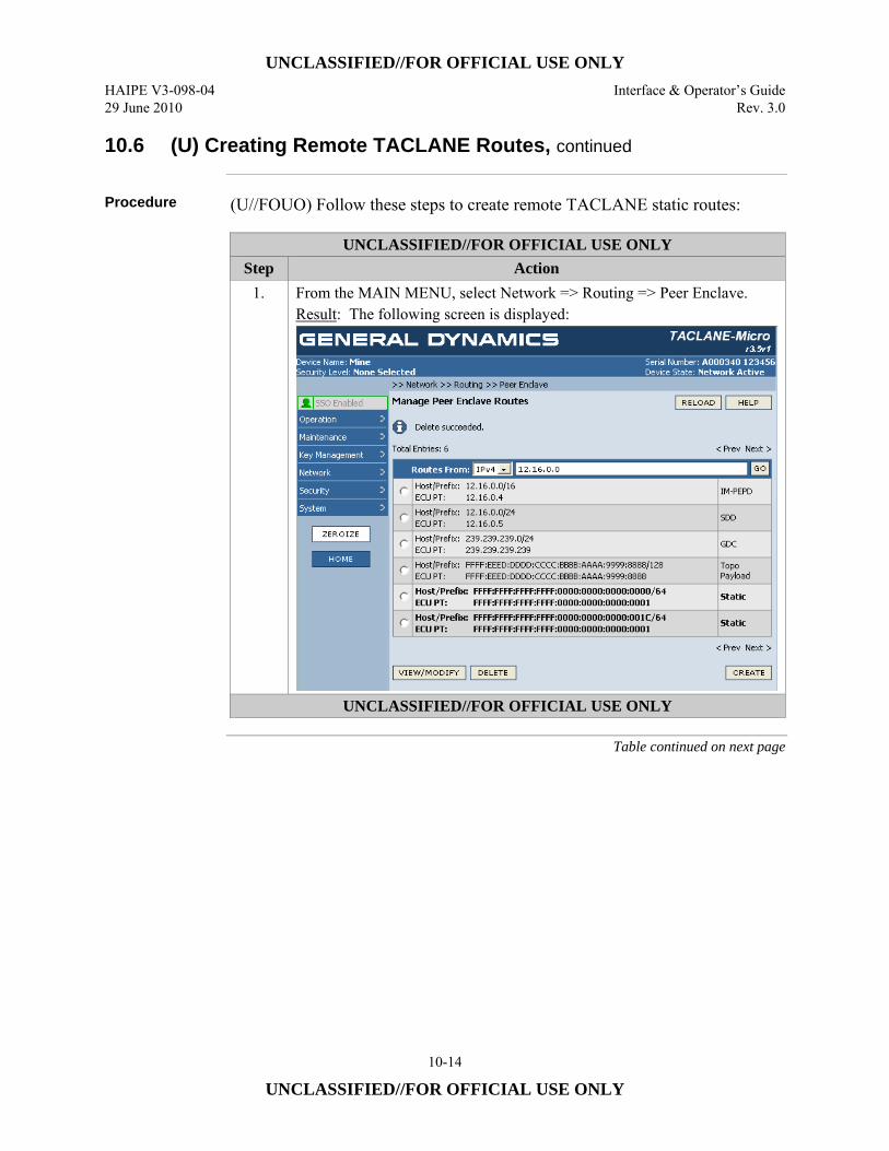
UNCLASSIFIED//FOR OFFICIAL USE ONLY HAIPE V3-098-04 Interface & Operator’s Guide 29 June 2010 Rev. 3.0
10-14
UNCLASSIFIED//FOR OFFICIAL USE ONLY
10.6 (U) Creating Remote TACLANE Routes, continued
Procedure (U//FOUO) Follow these steps to create remote TACLANE static routes:
UNCLASSIFIED//FOR OFFICIAL USE ONLY Step Action
1. From the MAIN MENU, select Network => Routing => Peer Enclave. Result: The following screen is displayed:
UNCLASSIFIED//FOR OFFICIAL USE ONLY
Table continued on next page
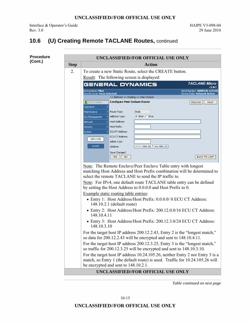
UNCLASSIFIED//FOR OFFICIAL USE ONLY Interface & Operator’s Guide HAIPE V3-098-04 Rev. 3.0 29 June 2010
10-15
UNCLASSIFIED//FOR OFFICIAL USE ONLY
10.6 (U) Creating Remote TACLANE Routes, continued
Procedure (Cont.)
UNCLASSIFIED//FOR OFFICIAL USE ONLY Step Action
2. To create a new Static Route, select the CREATE button. Result: The following screen is displayed:
Note: The Remote Enclave/Peer Enclave Table entry with longest matching Host Address and Host Prefix combination will be determined to select the remote TACLANE to send the IP traffic to. Note: For IPv4, one default route TACLANE table entry can be defined by setting the Host Address to 0.0.0.0 and Host Prefix to 0. Example static routing table entries: • Entry 1: Host Address/Host Prefix: 0.0.0.0/ 0 ECU CT Address:
148.10.2.1 (default route) • Entry 2: Host Address/Host Prefix: 200.12.0.0/16 ECU CT Address:
148.10.4.11 • Entry 3: Host Address/Host Prefix: 200.12.3.0/24 ECU CT Address:
148.10.3.10 For the target host IP address 200.12.2.43, Entry 2 is the “longest match,” so data for 200.12.2.43 will be encrypted and sent to 148.10.4.11. For the target host IP address 200.12.3.25, Entry 3 is the “longest match,” so traffic for 200.12.3.25 will be encrypted and sent to 148.10.3.10. For the target host IP address 10.24.105.26, neither Entry 2 nor Entry 3 is a match, so Entry 1 (the default route) is used. Traffic for 10.24.105.26 will be encrypted and sent to 148.10.2.1.
UNCLASSIFIED//FOR OFFICIAL USE ONLY
Table continued on next page
UNCLASSIFIED//FOR OFFICIAL USE ONLY HAIPE V3-098-04 Interface & Operator’s Guide 29 June 2010 Rev. 3.0
10-16
UNCLASSIFIED//FOR OFFICIAL USE ONLY
10.6 (U) Creating Remote TACLANE Routes, continued
Procedure (Cont.)
UNCLASSIFIED//FOR OFFICIAL USE ONLY Step Action
3. Enter the IP Address Type (IPv4 or IPv6). 4. Enter the Host Address. Format is XXX.XXX.XXX.XXX for IPv4;
XXXX:XXXX:XXXX:XXXX:XXXX:XXXX:XXXX:XXXX for IPv6. 5. Enter the Host Prefix (range is 1 to 32). 6. Enter the ECU CT Address. Format is XXX.XXX.XXX.XXX for IPv4;
XXXX:XXXX:XXXX:XXXX:XXXX:XXXX:XXXX:XXXX for IPv6. 7. Enter the ECU PT Address. Format is XXX.XXX.XXX.XXX for IPv4;
XXXX:XXXX:XXXX:XXXX:XXXX:XXXX:XXXX:XXXX for IPv6. 8. Enter the Admin Cost (range is 0 to 255). 9. Enter the Lifetime. Format is YYYY-MM-DD T HH:MM:SS.
10. Select the YES button to save changes. UNCLASSIFIED//FOR OFFICIAL USE ONLY
10.7 (U) Modifying Remote TACLANE Routes
Introduction (U//FOUO) The operator can modify routes in the Remote Enclave and Peer Enclave
Tables.
Notes (U//FOUO) The following notes apply to modifying remote TACLANE routes:
• Connected Routes cannot be modified. • The Addresses are not modifiable for SDD, GDC, IM-PEPD and Topo Payload
routes.
Continued on next page
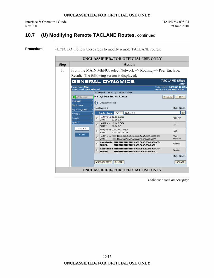
UNCLASSIFIED//FOR OFFICIAL USE ONLY Interface & Operator’s Guide HAIPE V3-098-04 Rev. 3.0 29 June 2010
10-17
UNCLASSIFIED//FOR OFFICIAL USE ONLY
10.7 (U) Modifying Remote TACLANE Routes, continued
Procedure (U//FOUO) Follow these steps to modify remote TACLANE routes:
UNCLASSIFIED//FOR OFFICIAL USE ONLY Step Action
1. From the MAIN MENU, select Network => Routing => Peer Enclave. Result: The following screen is displayed:
UNCLASSIFIED//FOR OFFICIAL USE ONLY
Table continued on next page
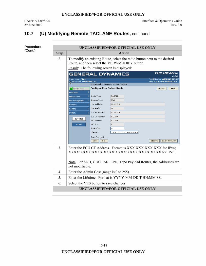
UNCLASSIFIED//FOR OFFICIAL USE ONLY HAIPE V3-098-04 Interface & Operator’s Guide 29 June 2010 Rev. 3.0
10-18
UNCLASSIFIED//FOR OFFICIAL USE ONLY
10.7 (U) Modifying Remote TACLANE Routes, continued
Procedure (Cont.)
UNCLASSIFIED//FOR OFFICIAL USE ONLY Step Action
2. To modify an existing Route, select the radio button next to the desired Route, and then select the VIEW/MODIFY button. Result: The following screen is displayed:
3. Enter the ECU CT Address. Format is XXX.XXX.XXX.XXX for IPv4; XXXX:XXXX:XXXX:XXXX:XXXX:XXXX:XXXX:XXXX for IPv6. Note: For SDD, GDC, IM-PEPD, Topo Payload Routes, the Addresses are not modifiable.
4. Enter the Admin Cost (range is 0 to 255). 5. Enter the Lifetime. Format is YYYY-MM-DD T HH:MM:SS. 6. Select the YES button to save changes.
UNCLASSIFIED//FOR OFFICIAL USE ONLY
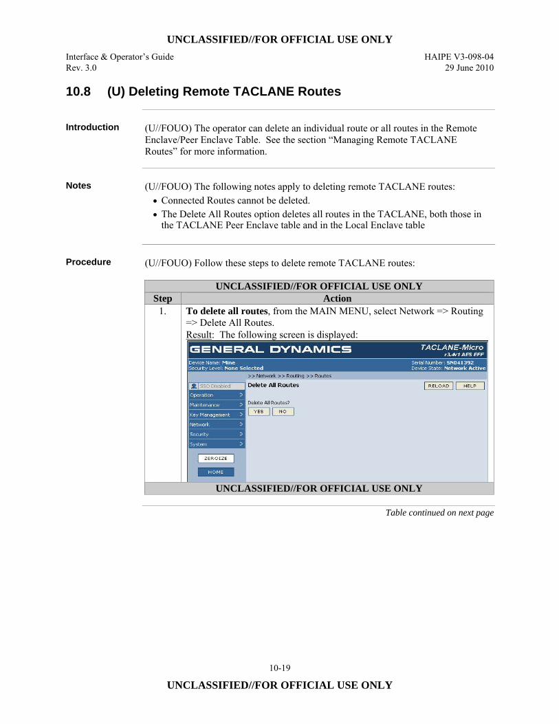
UNCLASSIFIED//FOR OFFICIAL USE ONLY Interface & Operator’s Guide HAIPE V3-098-04 Rev. 3.0 29 June 2010
10-19
UNCLASSIFIED//FOR OFFICIAL USE ONLY
10.8 (U) Deleting Remote TACLANE Routes
Introduction (U//FOUO) The operator can delete an individual route or all routes in the Remote
Enclave/Peer Enclave Table. See the section “Managing Remote TACLANE Routes” for more information.
Notes (U//FOUO) The following notes apply to deleting remote TACLANE routes:
• Connected Routes cannot be deleted. • The Delete All Routes option deletes all routes in the TACLANE, both those in
the TACLANE Peer Enclave table and in the Local Enclave table
Procedure (U//FOUO) Follow these steps to delete remote TACLANE routes:
UNCLASSIFIED//FOR OFFICIAL USE ONLY Step Action
1. To delete all routes, from the MAIN MENU, select Network => Routing => Delete All Routes. Result: The following screen is displayed:
UNCLASSIFIED//FOR OFFICIAL USE ONLY
Table continued on next page
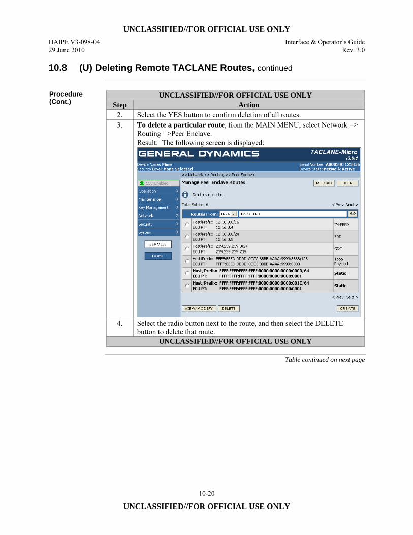
UNCLASSIFIED//FOR OFFICIAL USE ONLY HAIPE V3-098-04 Interface & Operator’s Guide 29 June 2010 Rev. 3.0
10-20
UNCLASSIFIED//FOR OFFICIAL USE ONLY
10.8 (U) Deleting Remote TACLANE Routes, continued
Procedure (Cont.)
UNCLASSIFIED//FOR OFFICIAL USE ONLY Step Action
2. Select the YES button to confirm deletion of all routes. 3. To delete a particular route, from the MAIN MENU, select Network =>
Routing =>Peer Enclave. Result: The following screen is displayed:
4. Select the radio button next to the route, and then select the DELETE button to delete that route.
UNCLASSIFIED//FOR OFFICIAL USE ONLY
Table continued on next page
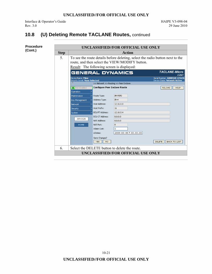
UNCLASSIFIED//FOR OFFICIAL USE ONLY Interface & Operator’s Guide HAIPE V3-098-04 Rev. 3.0 29 June 2010
10-21
UNCLASSIFIED//FOR OFFICIAL USE ONLY
10.8 (U) Deleting Remote TACLANE Routes, continued
Procedure (Cont.)
UNCLASSIFIED//FOR OFFICIAL USE ONLY Step Action
5. To see the route details before deleting, select the radio button next to the route, and then select the VIEW/MODIFY button. Result: The following screen is displayed:
6. Select the DELETE button to delete the route. UNCLASSIFIED//FOR OFFICIAL USE ONLY
UNCLASSIFIED//FOR OFFICIAL USE ONLY HAIPE V3-098-04 Interface & Operator’s Guide 29 June 2010 Rev. 3.0
10-22
UNCLASSIFIED//FOR OFFICIAL USE ONLY
10.9 (U) Creating Local TACLANE Routes
Introduction (U//FOUO) The Local Enclave Table provides a list of PT IP addresses/prefixes
protected by the TACLANE. Entries in the table may be made automatically, through the exchange of Router Information Protocol (RIP) with network devices located on the PT interface or through manual methods (static routes). (U//FOUO) When Generic Discovery Client functions are enabled, and the GDC Registration information is configured within the TACLANE, the information in the Local Enclave Prefix table will be sent to the GDC server to inform it that this TACLANE is protecting the PT host/networks contained within the Local Enclave Prefix table.
Local Enclave Table
(U//FOUO) The Local Enclave Table is used to associate destination IP network identifiers with the local TACLANE. • (U//FOUO) Up to 8196 route entries may be defined, including up to 1024 static
route entries. Entries resources are pooled; among remote enclave table entries and across all security levels.
• (U//FOUO) Entries consist of a Route Type (Static, RIP, Connected), IP Address Type (IPv4, IPv6), Host Address, Host Prefix, Administrative Cost, and Lifetime.
• (U//FOUO) Validation checks on table entries include: – No duplicate table entries (no two entries with the same network ID and
subnet mask). (The same network ID may be defined in multiple entries as long as the subnet masks are different.)
PT Default Gateway or ARP Used to Deliver PT IP Traffic
(U//FOUO) If the optional PT default gateway IP address is configured, all off-net decrypted PT IP traffic will be delivered to the PT default gateway. (U//FOUO) If the optional PT default gateway is not configured, TACLANE will ARP for all off-net destination IP addresses for decrypted PT IP traffic*. * (U//FOUO) Assumes proxy-ARP support in PT routers. Proxy-ARP allows a
router to reply to a received ARP request for a host in a network that is in the router’s routing table.
Continued on next page
UNCLASSIFIED//FOR OFFICIAL USE ONLY Interface & Operator’s Guide HAIPE V3-098-04 Rev. 3.0 29 June 2010
10-23
UNCLASSIFIED//FOR OFFICIAL USE ONLY
10.9 (U) Creating Local TACLANE Routes, continued
Notes (U//FOUO) The following notes apply to creating local TACLANE routes:
• (U//FOUO) Routes can be associated with subnets, portions of subnets, or specific host addresses. The granularity of scope is controlled by the prefix setting.
• (U//FOUO) Static Routes are bolded; Connected and Dynamic Routes are not bolded.
• Host Address must be a unicast IP address or a multicast IP address. • Lifetime cannot be set to a value such that the entry would already be expired
when the route is created. (U//FOUO) The following notes apply to the “Routes From:” navigation tool on the Manage Routes screen: • (U//FOUO) The Host IP address entered in the navigation tool must be the same
version as the selected IP version (IPv4 or IPv6). • (U//FOUO) The Host IP address entered must be a complete address. • (U//FOUO) Select the GO button to display the Route list starting with the
entered Host IP address. • (U//FOUO) Each page displays from the beginning of the Route list or from the
Host IP address entered in the navigation tool. • (U//FOUO) Selecting the RELOAD button restores the table view, beginning
with the first page of the table.
Continued on next page

UNCLASSIFIED//FOR OFFICIAL USE ONLY HAIPE V3-098-04 Interface & Operator’s Guide 29 June 2010 Rev. 3.0
10-24
UNCLASSIFIED//FOR OFFICIAL USE ONLY
10.9 (U) Creating Local TACLANE Routes, continued
Procedure (U//FOUO) Follow these steps to create entries in the local enclave table:
UNCLASSIFIED//FOR OFFICIAL USE ONLY Step Action
1. From the MAIN MENU, select Network => Routing => Local Enclave. Result: The following screen is displayed:
UNCLASSIFIED//FOR OFFICIAL USE ONLY
Table continued on next page

UNCLASSIFIED//FOR OFFICIAL USE ONLY Interface & Operator’s Guide HAIPE V3-098-04 Rev. 3.0 29 June 2010
10-25
UNCLASSIFIED//FOR OFFICIAL USE ONLY
10.9 (U) Creating Local TACLANE Routes, continued
Procedure (Cont.)
UNCLASSIFIED//FOR OFFICIAL USE ONLY Step Action
2. To create a new Static Route, select the CREATE button. Result: The following screen is displayed:
Note: The Local Enclave Table entry is used to assist in discovery. The TACLANE reports information in this table to discovery servers and processes (GDC and SDD) which are trying to determine what PT hosts or networks the TACLANE protects. Example static routing table entries: • Entry 1: Host Address/Host Prefix: 200.12.0.0, Host Prefix 16 • Entry 2: Host Address/Host Prefix: 200.12.3.0, Host Prefix 24
3. Enter the IP Address Type (IPv4 or IPv6). 4. Enter the Host Address. Format is XXX.XXX.XXX.XXX for IPv4;
XXXX:XXXX:XXXX:XXXX:XXXX:XXXX:XXXX:XXXX for IPv6. 5. Enter the Host Prefix (range is 1 to 32). 6. Enter the Admin Cost (range is 0 to 255). 7. Enter the Lifetime. Format is YYYY-MM-DD T HH:MM:SS. 8. Select the YES button to save changes.
UNCLASSIFIED//FOR OFFICIAL USE ONLY
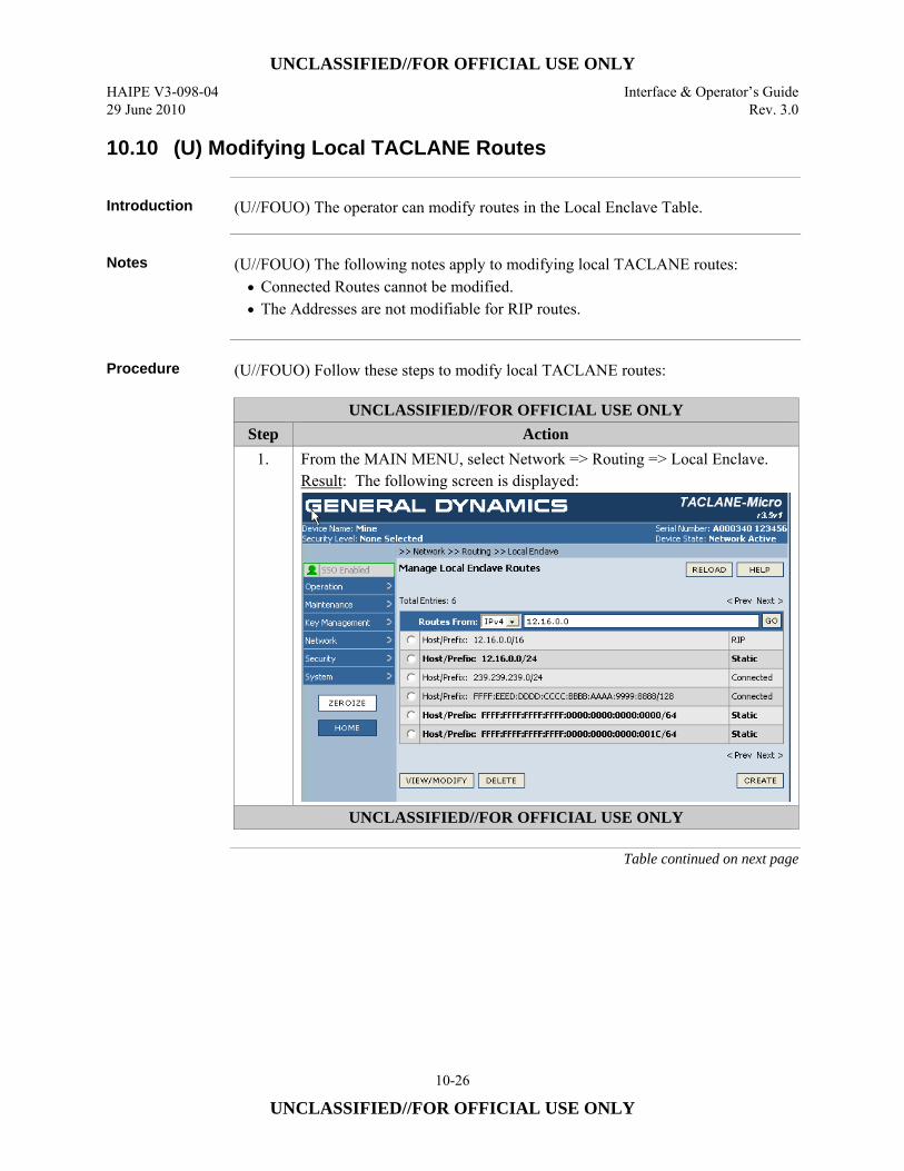
UNCLASSIFIED//FOR OFFICIAL USE ONLY HAIPE V3-098-04 Interface & Operator’s Guide 29 June 2010 Rev. 3.0
10-26
UNCLASSIFIED//FOR OFFICIAL USE ONLY
10.10 (U) Modifying Local TACLANE Routes
Introduction (U//FOUO) The operator can modify routes in the Local Enclave Table.
Notes (U//FOUO) The following notes apply to modifying local TACLANE routes:
• Connected Routes cannot be modified. • The Addresses are not modifiable for RIP routes.
Procedure (U//FOUO) Follow these steps to modify local TACLANE routes:
UNCLASSIFIED//FOR OFFICIAL USE ONLY Step Action
1. From the MAIN MENU, select Network => Routing => Local Enclave. Result: The following screen is displayed:
UNCLASSIFIED//FOR OFFICIAL USE ONLY
Table continued on next page

UNCLASSIFIED//FOR OFFICIAL USE ONLY Interface & Operator’s Guide HAIPE V3-098-04 Rev. 3.0 29 June 2010
10-27
UNCLASSIFIED//FOR OFFICIAL USE ONLY
10.10 (U) Modifying Local TACLANE Routes, continued
Procedure (Cont.)
UNCLASSIFIED//FOR OFFICIAL USE ONLY Step Action
2. To modify an existing Route, select the radio button next to the desired Route, and then select the VIEW/MODIFY button. Result: The following screen is displayed:
3. Enter the Admin Cost (range is 0 to 255). 4. Enter the Lifetime. Format is YYYY-MM-DD T HH:MM:SS. 5. Select the YES button to save changes.
UNCLASSIFIED//FOR OFFICIAL USE ONLY
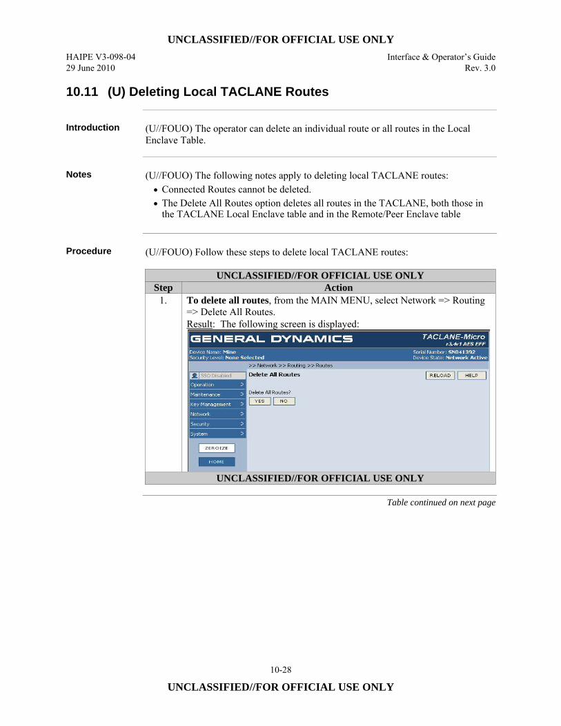
UNCLASSIFIED//FOR OFFICIAL USE ONLY HAIPE V3-098-04 Interface & Operator’s Guide 29 June 2010 Rev. 3.0
10-28
UNCLASSIFIED//FOR OFFICIAL USE ONLY
10.11 (U) Deleting Local TACLANE Routes
Introduction (U//FOUO) The operator can delete an individual route or all routes in the Local
Enclave Table.
Notes (U//FOUO) The following notes apply to deleting local TACLANE routes:
• Connected Routes cannot be deleted. • The Delete All Routes option deletes all routes in the TACLANE, both those in
the TACLANE Local Enclave table and in the Remote/Peer Enclave table
Procedure (U//FOUO) Follow these steps to delete local TACLANE routes:
UNCLASSIFIED//FOR OFFICIAL USE ONLY Step Action
1. To delete all routes, from the MAIN MENU, select Network => Routing => Delete All Routes. Result: The following screen is displayed:
UNCLASSIFIED//FOR OFFICIAL USE ONLY
Table continued on next page
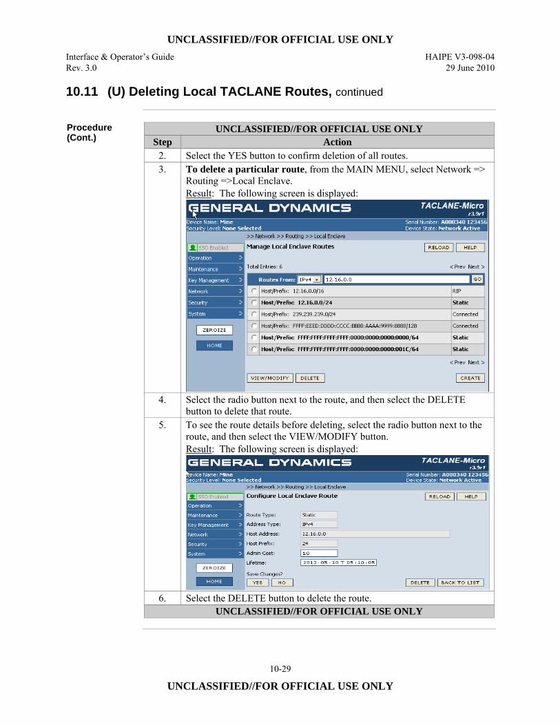
UNCLASSIFIED//FOR OFFICIAL USE ONLY Interface & Operator’s Guide HAIPE V3-098-04 Rev. 3.0 29 June 2010
10-29
UNCLASSIFIED//FOR OFFICIAL USE ONLY
10.11 (U) Deleting Local TACLANE Routes, continued
Procedure (Cont.)
UNCLASSIFIED//FOR OFFICIAL USE ONLY Step Action
2. Select the YES button to confirm deletion of all routes. 3. To delete a particular route, from the MAIN MENU, select Network =>
Routing =>Local Enclave. Result: The following screen is displayed:
4. Select the radio button next to the route, and then select the DELETE button to delete that route.
5. To see the route details before deleting, select the radio button next to the route, and then select the VIEW/MODIFY button. Result: The following screen is displayed:
6. Select the DELETE button to delete the route. UNCLASSIFIED//FOR OFFICIAL USE ONLY
UNCLASSIFIED//FOR OFFICIAL USE ONLY HAIPE V3-098-04 Interface & Operator’s Guide 29 June 2010 Rev. 3.0
10-30
UNCLASSIFIED//FOR OFFICIAL USE ONLY
10.12 (U) Enabling RIP Listener
Introduction (U//FOUO) RIP Listener may be enabled or disabled by an operator. There is a
separate setting for IPv4 and IPv6.
Notes (U//FOUO) The following notes apply to configuring RIP Listener
• (U//FOUO) Enabling RIP Listener will allow the ECU to learn about networks or hosts which are available on the PT interface through the use of RIP. Routers located on the PT interface will advertise routes regarding these hosts or networks using RIP which the TACLANE will be able to read and learn about their presence.
• (U//FOUO) RIP Listener is disabled by default • (U//FOUO) TACLANE is compatible with RIPv1, RIPv2 and RIPng • (U//FOUO) RIP learned routes are advertised to the Generic Client Discovery
Server.
Continued on next page
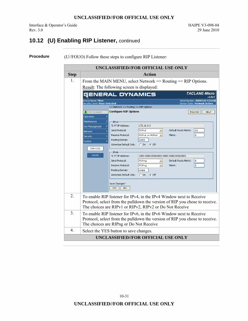
UNCLASSIFIED//FOR OFFICIAL USE ONLY Interface & Operator’s Guide HAIPE V3-098-04 Rev. 3.0 29 June 2010
10-31
UNCLASSIFIED//FOR OFFICIAL USE ONLY
10.12 (U) Enabling RIP Listener, continued
Procedure (U//FOUO) Follow these steps to configure RIP Listener:
UNCLASSIFIED//FOR OFFICIAL USE ONLY Step Action
1. From the MAIN MENU, select Network => Routing => RIP Options. Result: The following screen is displayed:
2. To enable RIP listener for IPv4, in the IPv4 Window next to Receive Protocol, select from the pulldown the version of RIP you chose to receive. The choices are RIPv1 or RIPv2, RIPv2 or Do Not Receive
3. To enable RIP listener for IPv6, in the IPv6 Window next to Receive Protocol, select from the pulldown the version of RIP you chose to receive. The choices are RIPng or Do Not Receive
4. Select the YES button to save changes. UNCLASSIFIED//FOR OFFICIAL USE ONLY

UNCLASSIFIED//FOR OFFICIAL USE ONLY HAIPE V3-098-04 Interface & Operator’s Guide 29 June 2010 Rev. 3.0
10-32
UNCLASSIFIED//FOR OFFICIAL USE ONLY
10.13 (U) Disabling RIP Listener
Introduction (U//FOUO) RIP Listener may be disabled by an operator. There is a separate setting
for IPv4 and IPv6
Notes (U//FOUO) The following notes apply to configuring RIP Listener
• (U//FOUO) Disabling RIP listener will prevent the TACLANE from learning information about host or networks on the PT network that are advertised using RIP.
Procedure (U//FOUO) Follow these steps to disable RIP Listener:
UNCLASSIFIED//FOR OFFICIAL USE ONLY Step Action
1. From the MAIN MENU, select Network => Routing => RIP Options. Result: The following screen is displayed:
2. To disable RIP listener for IPv4, in the IPv4 Window next to Receive Protocol, select from the pulldown Do Not Receive.
3. To enable RIP listener for IPv6, in the IPv6 Window next to Receive Protocol, select from the pulldown Do Not Receive.
4. Select the YES button to save changes. UNCLASSIFIED//FOR OFFICIAL USE ONLY
UNCLASSIFIED//FOR OFFICIAL USE ONLY Interface & Operator’s Guide HAIPE V3-098-04 Rev. 3.0 29 June 2010
10-33
UNCLASSIFIED//FOR OFFICIAL USE ONLY
10.14 (U) Enabling RIP Speaker
Introduction (U//FOUO) RIP Speaker may be enabled or disabled by an operator. There are
separate settings for IPv4 and IPv6
Notes (U//FOUO) The following notes apply to configuring RIP Speaker
• (U//FOUO) RIP Speaker allows the TACLANE to transmit RIP advertisements from the PT interface which contain remote PT networks or hosts that are reachable through established SAs.
• (U//FOUO) RIP Speaker is capable of advertising a default route. This will inform any devices listening to forward their traffic to the TACLANE.
• (U//FOUO) RIP advertisement sent by TACLANE will send routes with a configurable metric. The default route can also be advertised with a configurable metric. The metric may be set from 0 to 15. A value of 0 will disable the advertisement.
• (U//FOUO) RIP advertisements sent by TACLANE will send routes with a configurable route tag. By default the route tag is set to 0.
• (U//FOUO) The RIP Speaker function allows the TACLANE to advertise only the default route if desired.
• (U//FOUO) In order for the TACLANE to advertise routes for remote PT networks, the RIP Send Protocol and Metric need to be configured to valid values. Additionally, the Security Association connecting the TACLANE to the remote TACLANE or HAIPE device which protects the remote PT network, needs to be established.
Continued on next page
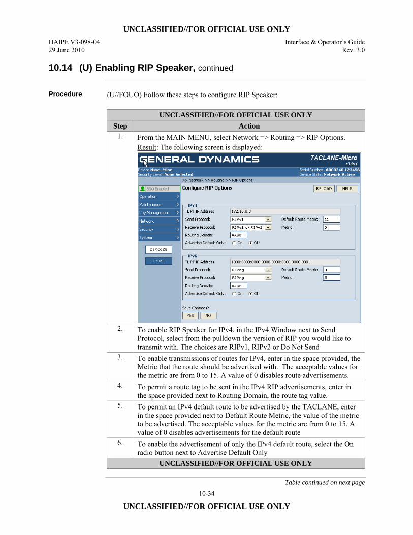
UNCLASSIFIED//FOR OFFICIAL USE ONLY HAIPE V3-098-04 Interface & Operator’s Guide 29 June 2010 Rev. 3.0
10-34
UNCLASSIFIED//FOR OFFICIAL USE ONLY
10.14 (U) Enabling RIP Speaker, continued
Procedure (U//FOUO) Follow these steps to configure RIP Speaker:
UNCLASSIFIED//FOR OFFICIAL USE ONLY Step Action
1. From the MAIN MENU, select Network => Routing => RIP Options. Result: The following screen is displayed:
2. To enable RIP Speaker for IPv4, in the IPv4 Window next to Send Protocol, select from the pulldown the version of RIP you would like to transmit with. The choices are RIPv1, RIPv2 or Do Not Send
3. To enable transmissions of routes for IPv4, enter in the space provided, the Metric that the route should be advertised with. The acceptable values for the metric are from 0 to 15. A value of 0 disables route advertisements.
4. To permit a route tag to be sent in the IPv4 RIP advertisements, enter in the space provided next to Routing Domain, the route tag value.
5. To permit an IPv4 default route to be advertised by the TACLANE, enter in the space provided next to Default Route Metric, the value of the metric to be advertised. The acceptable values for the metric are from 0 to 15. A value of 0 disables advertisements for the default route
6. To enable the advertisement of only the IPv4 default route, select the On radio button next to Advertise Default Only
UNCLASSIFIED//FOR OFFICIAL USE ONLY
Table continued on next page
UNCLASSIFIED//FOR OFFICIAL USE ONLY Interface & Operator’s Guide HAIPE V3-098-04 Rev. 3.0 29 June 2010
10-35
UNCLASSIFIED//FOR OFFICIAL USE ONLY
10.14 (U) Enabling RIP Speaker, continued
Procedure (Cont.)
UNCLASSIFIED//FOR OFFICIAL USE ONLY Step Action
7. To enable RIP Speaker for IPv6, in the IPv6 Window next to Send Protocol, select from the pulldown the version of RIP you would like to transmit with. There is only one version of RIP supported for IPv6 which is RIPng.
8. To enable transmissions of routes for IPv6, enter in the space provided, the Metric that the route should be advertised with. The acceptable values for the metric are from 0 to 15. A value of 0 disables route advertisements.
9. To permit a route tag to be sent in the IPv6 RIP advertisements, enter in the space provided next to Routing Domain, the route tag value.
10. To permit an IPv6 default route to be advertised by the TACLANE, enter in the space provided next to Default Route Metric, the value of the metric to be advertised. The acceptable values for the metric are from 0 to 15. A value of 0 disables advertisements for the default route
11. To enable the advertisement of only the IPv6 default route, select the On radio button next to Advertise Default Only
12. Select the YES button to save changes. UNCLASSIFIED//FOR OFFICIAL USE ONLY
10.15 (U) Disabling RIP Speaker
Introduction (U//FOUO) RIP Speaker may be disabled by an operator. There is a setting for IPv4
and IPv6
Notes (U//FOUO) The following notes apply to configuring RIP Speaker
• (U//FOUO) Disabling RIP Speaker will prevent the TACLANE from transmitting from the PT interface RIP advertisements announcing which remote PT networks or host are reachable through established SAs with peer TACLANEs or HAIPE devices.
Continued on next page

UNCLASSIFIED//FOR OFFICIAL USE ONLY HAIPE V3-098-04 Interface & Operator’s Guide 29 June 2010 Rev. 3.0
10-36
UNCLASSIFIED//FOR OFFICIAL USE ONLY
10.15 (U) Disabling RIP Speaker, continued
Procedure (U//FOUO) Follow these steps to disable RIP Speaker:
UNCLASSIFIED//FOR OFFICIAL USE ONLY Step Action
1. From the MAIN MENU, select Network => Routing => RIP Options. Result: The following screen is displayed:
2. To disable RIP Speaker for IPv4, in the IPv4 Window next to Send Protocol, select from the pulldown Do Not Send
3. To enable RIP Speaker for IPv6, in the IPv6 Window next to Send Protocol, select from the pulldown Do Not Send
4. Select the YES button to save changes. UNCLASSIFIED//FOR OFFICIAL USE ONLY
UNCLASSIFIED//FOR OFFICIAL USE ONLY Interface & Operator’s Guide HAIPE V3-098-04 Rev. 3.0 29 June 2010
10-37
UNCLASSIFIED//FOR OFFICIAL USE ONLY
10.16 (U) Creating PPK SAs
Introduction (U//FOUO) PPK SAs are static security associations used to protect traffic to peer
HAIPEs.
Per-PPK SA Traffic Flow Security
(U//FOUO) The TACLANE supports per-SA IP Traffic Flow Security (TFS) features that are required by the HAIPE Interoperability Specification (IS). When configured appropriately, the IP TFS features in the TACLANE prevent/reduce compromise of sensitive information due to certain types of attacks. The per-PPK SA TFS settings include: • DF Bit Bypass • ECN Bypass • DSCP Bypass • Flow Label Bypass
(U//FOUO) There are important security and performance trade-offs that should be considered when enabling and disabling TFS countermeasures. For descriptions of these tradeoffs, along with recommended network and equipment configurations that minimize security risks, please refer to the TACLANE Security Features Users Guide.
DF Bit Bypass (U//FOUO) Don’t Fragment (DF) bit bypass is used to support PMTU discovery. DF
Bit bypass parameter can be configured in one of three ways: • (U//FOUO) SET: Always sets the DF bit in the CT IP header to “1” • (U//FOUO) CLEAR: Always sets the DF bit in the CT IP header to “0” • (U//FOUO) COPY: Copies the DF bit value from the PT IP header to the CT
ESP IP header DF bit value (U//FOUO) The DF Bit bypass setting affects FPL and PMTU processing. See those sections for details. (U//FOUO) The DF bit bypass setting has no effect on IPv6 SAs, as the DF bit does not exist in IPv6.
Continued on next page
UNCLASSIFIED//FOR OFFICIAL USE ONLY HAIPE V3-098-04 Interface & Operator’s Guide 29 June 2010 Rev. 3.0
10-38
UNCLASSIFIED//FOR OFFICIAL USE ONLY
10.16 (U) Creating PPK SAs, continued
ECN Bypass (U//FOUO) Explicit Congestion Notification (ECN) bypass can be used to support
network congestion control. ECN bypass can be configured in one of three ways: • (U//FOUO) OFF:
– Always sets the ECN bits in the CT ESP IP header to “10” binary. – For a Transport Mode SA, the reconstructed PT IP header ECN bits are set
to “00” before the PT IP datagram is sent on the PT network. • (U//FOUO) ON-CONGESTION:
– Always sets the ECN bits in the CT ESP IP header to “10” binary. – For a Tunnel Mode SA, if the received CT ESP IP header ECN bits are “11”,
and the decrypted PT IP header ECN bits are “10” or “01”, the decrypted PT IP header ECN bits are changed to “11” before the PT IP datagram is sent on the PT network.
– For a Transport Mode SA, if the received CT ESP IP header ECN bits are “11”, the reconstructed PT IP header ECN bits are set to “11” before the PT IP datagram is sent on the PT network.
– For a Transport Mode SA, if the received CT ESP IP header ECN bits are “10”, “00”, or “01”, the reconstructed PT IP header ECN bits are set to “10” before the PT IP datagram is sent on the PT network.
• (U//FOUO) ON-ADMISSION: – Copies the ECN bits from the PT IP header to the CT IP header. – Copies the ECN bits from the CT IP header to the PT IP header.
Flow Label Bypass
(U//FOUO) Flow Label Bypass only applies to IPv6 traffic. Enabling Flow Label bypass permits the 20 Bit Flow Label field in the IPv6 Header to be bypassed from the PT interface to the CT interface. Disabling Flow Label bypass blocks the Flow Label value from being bypassed in the PT to CT direction. The TACLANE sets the Flow Label value to 0 on the CT interface. Flow Label bypass only applies to traffic traveling from the PT interface to the CT interface: • (U//FOUO) OFF: Flow Label not bypassed, value is set to 0. • (U//FOUO) ON: Flow Label value is bypassed from the PT side to the CT side.
DSCP Bypass (U//FOUO) DSCP bypass is configurable on a per-PPK SA basis. Each PPK SA can
be configured to either: • (U//FOUO) DISABLED – overwrite CT DSCP value to zero. This DSCP value
is used in the CT ESP IP header for all ESP traffic generated using a PPK SA. • (U//FOUO) ENABLED – select which of the 64 DSCP values allowed to be
bypassed. Any allowed bypass value is copied from the PT IP header to the CT ESP IP header.
Continued on next page
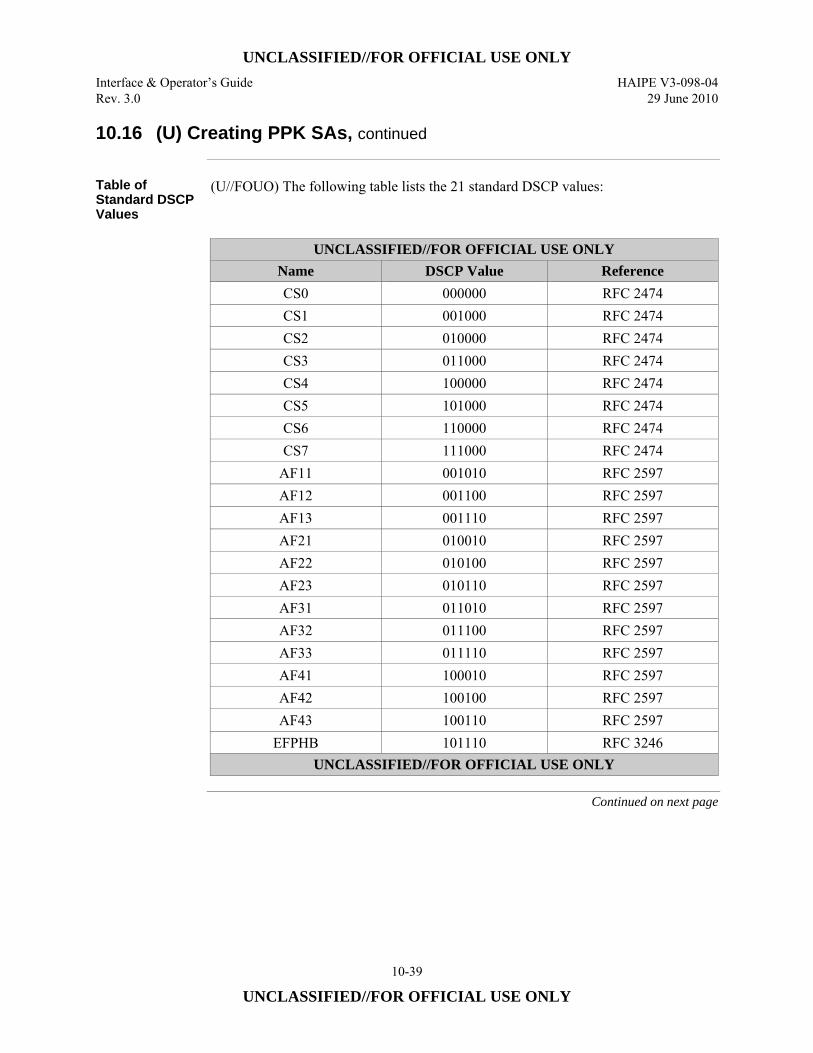
UNCLASSIFIED//FOR OFFICIAL USE ONLY Interface & Operator’s Guide HAIPE V3-098-04 Rev. 3.0 29 June 2010
10-39
UNCLASSIFIED//FOR OFFICIAL USE ONLY
10.16 (U) Creating PPK SAs, continued
Table of Standard DSCP Values
(U//FOUO) The following table lists the 21 standard DSCP values:
UNCLASSIFIED//FOR OFFICIAL USE ONLY
Name DSCP Value Reference CS0 000000 RFC 2474 CS1 001000 RFC 2474 CS2 010000 RFC 2474 CS3 011000 RFC 2474 CS4 100000 RFC 2474 CS5 101000 RFC 2474 CS6 110000 RFC 2474 CS7 111000 RFC 2474
AF11 001010 RFC 2597 AF12 001100 RFC 2597 AF13 001110 RFC 2597 AF21 010010 RFC 2597 AF22 010100 RFC 2597 AF23 010110 RFC 2597 AF31 011010 RFC 2597 AF32 011100 RFC 2597 AF33 011110 RFC 2597 AF41 100010 RFC 2597 AF42 100100 RFC 2597 AF43 100110 RFC 2597
EFPHB 101110 RFC 3246 UNCLASSIFIED//FOR OFFICIAL USE ONLY
Continued on next page
UNCLASSIFIED//FOR OFFICIAL USE ONLY HAIPE V3-098-04 Interface & Operator’s Guide 29 June 2010 Rev. 3.0
10-40
UNCLASSIFIED//FOR OFFICIAL USE ONLY
10.16 (U) Creating PPK SAs, continued
Notes (U//FOUO) The following notes apply to creating PPK SAs:
• (U//FOUO) Only the SSO can create a PPK SA. • (U//FOUO) Maximum number of PPK SAs that can be configured is based on a
total number of supported bi-directional SAs (FF or PPK SAs). The maximum number of bidirectional SAs is equal to 512 for TACLANE-Micro and 4096 for TACLANE-GigE. – PPK SAs associated with Suite A or Suite B PPK Chains with only the
FIRST SET of SPI/DATE fields configured represent two (IN-Current/OUT-Current) unidirectional SAs.
– PPK SAs associated with Suite A or Suite B PPK Chains with both the FIRST PAIR and the SECOND PAIR of SPI/DATE fields configured represent four (IN-Current/OUT-Current/IN-Next/OUT-Next) unidirectional SAs.
– PPK SAs associated with Legacy PPK Chains represent two (IN-Current/OUT-Current) to four ((IN-Current/OUT-Current/IN-Next/OUT-Next) during update/changeover window) unidirectional SAs at any given time.
• (U//FOUO) Multiple PPK SAs can be associated with the same PPK Chain. • (U//FOUO) The desired PPK Chain must be filled in order to create a PPK SA
associated with that PPK Chain ID. • (U//FOUO) Transport Mode PPK SAs cannot be created if FPL is enabled. • (U//FOUO) Transport Mode PPK SAs cannot be created with Legacy PPK
Chains • (U//FOUO) If Control Plane Signaling is not enabled for a Transport Mode PPK
SA then the Transport Mode PPK SA cannot be created unless PPK PDUN Transmit is disabled and the PPK PHRD Rate is disabled.
• (U//FOUO) A multicast Transport Mode PPK SA must be associated with a Transport Mode Address map that contains a multicast destination address.
• (U//FOUO) A unicast Transport Mode PPK SA must be associated with a Transport Mode Address map that contains a unicast destination address.
• (U//FOUO) If CT Stateless Address Autoconfiguration (SAA) and Duplicate Address Detection (DAD) are enabled, only Auto-configure PPK SA Local CT Addresses are allowed.
• (U//FOUO) If the PPK Chain ID selected is a PPK Chain with an encryption algorithm equal to BATON, the integrity algorithm/crypto block size must be set to BIP-32/48(Legacy)
• (U//FOUO) PPK SAs using PPK Chains of particular classifications other than the current operating security level are not established.
Continued on next page
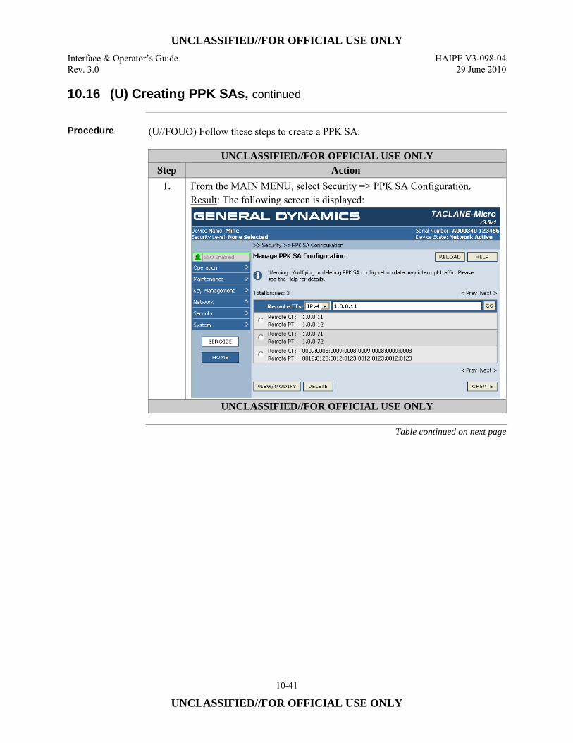
UNCLASSIFIED//FOR OFFICIAL USE ONLY Interface & Operator’s Guide HAIPE V3-098-04 Rev. 3.0 29 June 2010
10-41
UNCLASSIFIED//FOR OFFICIAL USE ONLY
10.16 (U) Creating PPK SAs, continued
Procedure (U//FOUO) Follow these steps to create a PPK SA:
UNCLASSIFIED//FOR OFFICIAL USE ONLY Step Action
1. From the MAIN MENU, select Security => PPK SA Configuration. Result: The following screen is displayed:
UNCLASSIFIED//FOR OFFICIAL USE ONLY
Table continued on next page
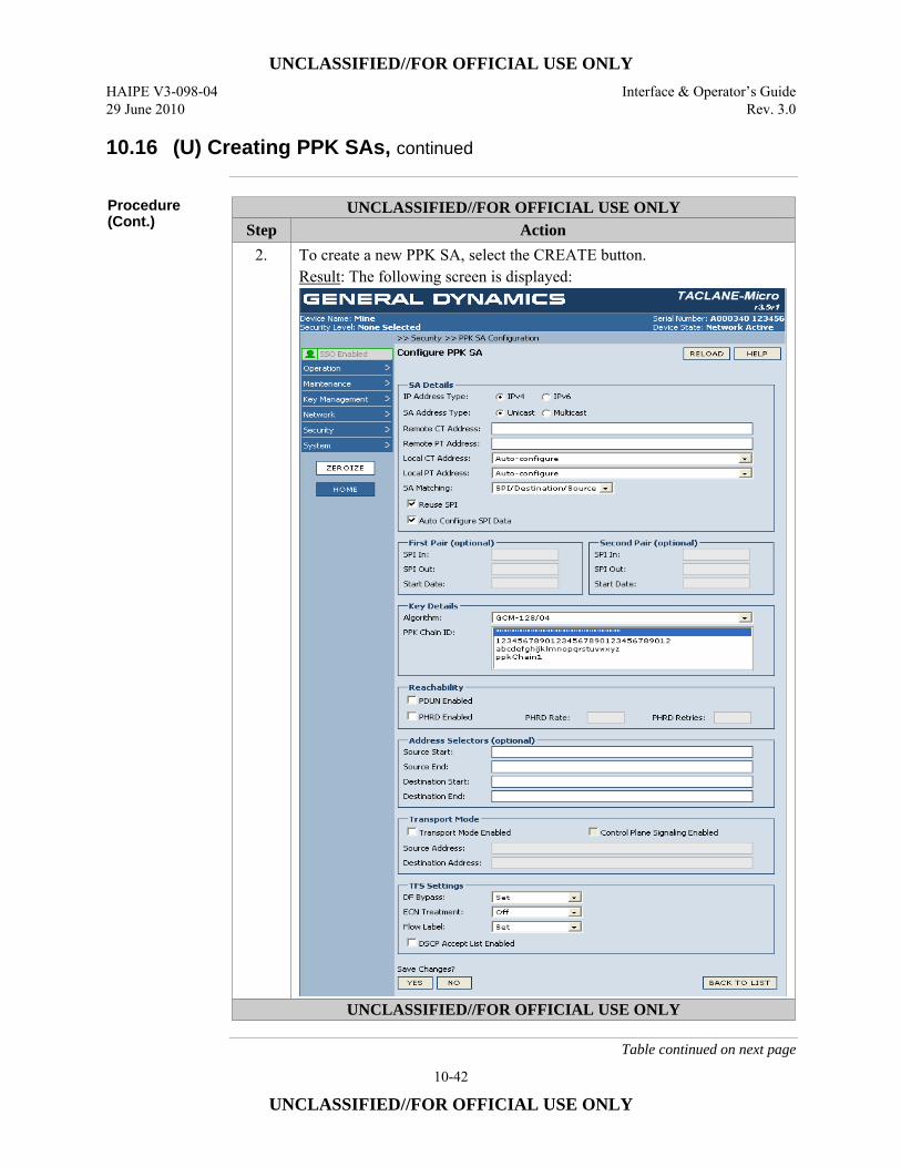
UNCLASSIFIED//FOR OFFICIAL USE ONLY HAIPE V3-098-04 Interface & Operator’s Guide 29 June 2010 Rev. 3.0
10-42
UNCLASSIFIED//FOR OFFICIAL USE ONLY
10.16 (U) Creating PPK SAs, continued
Procedure (Cont.)
UNCLASSIFIED//FOR OFFICIAL USE ONLY Step Action
2. To create a new PPK SA, select the CREATE button. Result: The following screen is displayed:
UNCLASSIFIED//FOR OFFICIAL USE ONLY
Table continued on next page
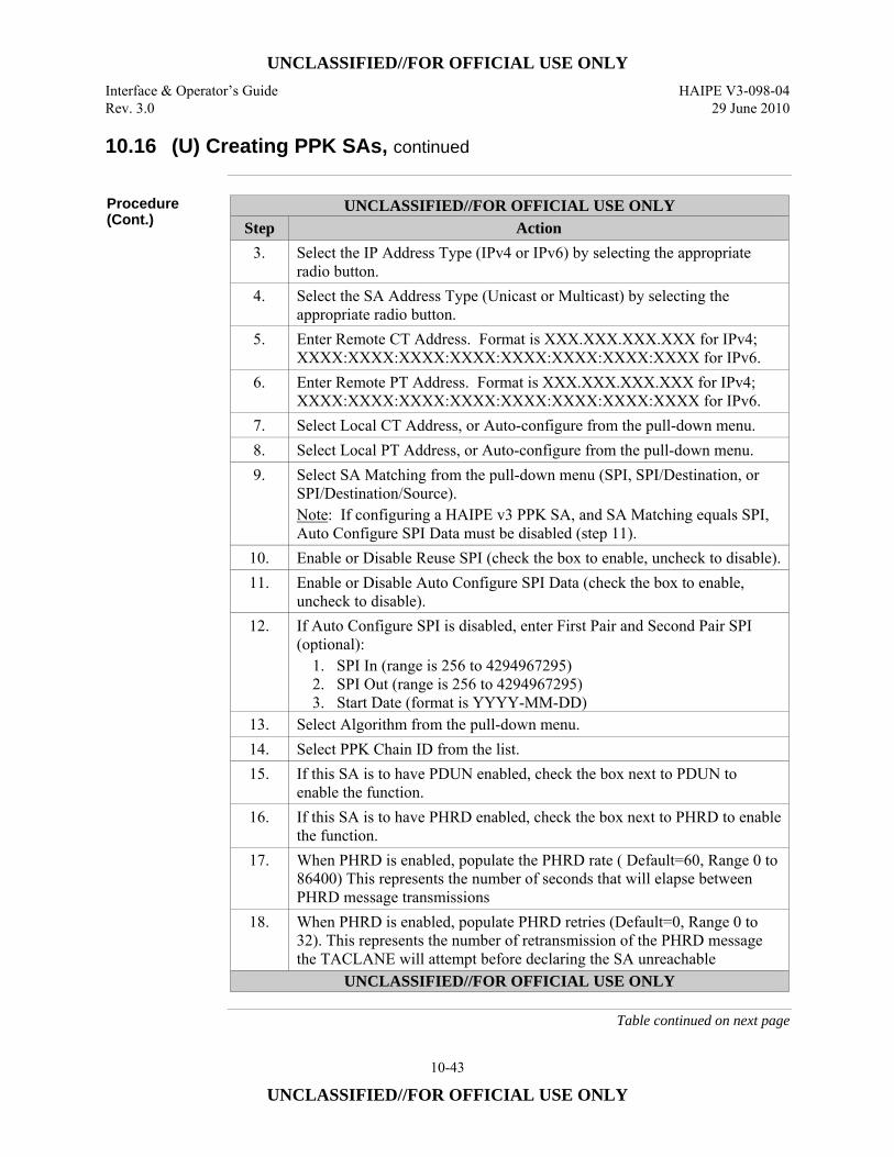
UNCLASSIFIED//FOR OFFICIAL USE ONLY Interface & Operator’s Guide HAIPE V3-098-04 Rev. 3.0 29 June 2010
10-43
UNCLASSIFIED//FOR OFFICIAL USE ONLY
10.16 (U) Creating PPK SAs, continued
Procedure (Cont.)
UNCLASSIFIED//FOR OFFICIAL USE ONLY Step Action
3. Select the IP Address Type (IPv4 or IPv6) by selecting the appropriate radio button.
4. Select the SA Address Type (Unicast or Multicast) by selecting the appropriate radio button.
5. Enter Remote CT Address. Format is XXX.XXX.XXX.XXX for IPv4; XXXX:XXXX:XXXX:XXXX:XXXX:XXXX:XXXX:XXXX for IPv6.
6. Enter Remote PT Address. Format is XXX.XXX.XXX.XXX for IPv4; XXXX:XXXX:XXXX:XXXX:XXXX:XXXX:XXXX:XXXX for IPv6.
7. Select Local CT Address, or Auto-configure from the pull-down menu. 8. Select Local PT Address, or Auto-configure from the pull-down menu. 9. Select SA Matching from the pull-down menu (SPI, SPI/Destination, or
SPI/Destination/Source). Note: If configuring a HAIPE v3 PPK SA, and SA Matching equals SPI, Auto Configure SPI Data must be disabled (step 11).
10. Enable or Disable Reuse SPI (check the box to enable, uncheck to disable).11. Enable or Disable Auto Configure SPI Data (check the box to enable,
uncheck to disable). 12. If Auto Configure SPI is disabled, enter First Pair and Second Pair SPI
(optional): 1. SPI In (range is 256 to 4294967295) 2. SPI Out (range is 256 to 4294967295) 3. Start Date (format is YYYY-MM-DD)
13. Select Algorithm from the pull-down menu. 14. Select PPK Chain ID from the list. 15. If this SA is to have PDUN enabled, check the box next to PDUN to
enable the function. 16. If this SA is to have PHRD enabled, check the box next to PHRD to enable
the function. 17. When PHRD is enabled, populate the PHRD rate ( Default=60, Range 0 to
86400) This represents the number of seconds that will elapse between PHRD message transmissions
18. When PHRD is enabled, populate PHRD retries (Default=0, Range 0 to 32). This represents the number of retransmission of the PHRD message the TACLANE will attempt before declaring the SA unreachable
UNCLASSIFIED//FOR OFFICIAL USE ONLY
Table continued on next page
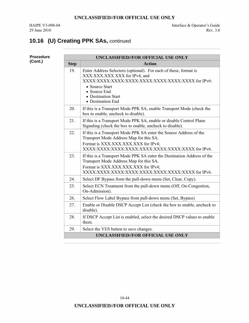
UNCLASSIFIED//FOR OFFICIAL USE ONLY HAIPE V3-098-04 Interface & Operator’s Guide 29 June 2010 Rev. 3.0
10-44
UNCLASSIFIED//FOR OFFICIAL USE ONLY
10.16 (U) Creating PPK SAs, continued
Procedure (Cont.)
UNCLASSIFIED//FOR OFFICIAL USE ONLY Step Action 19. Enter Address Selectors (optional). For each of these, format is
XXX.XXX.XXX.XXX for IPv4, and XXXX:XXXX:XXXX:XXXX:XXXX:XXXX:XXXX:XXXX for IPv6: • Source Start • Source End • Destination Start • Destination End
20. If this is a Transport Mode PPK SA, enable Transport Mode (check the box to enable, uncheck to disable).
21. If this is a Transport Mode PPK SA, enable or disable Control Plane Signaling (check the box to enable, uncheck to disable).
22. If this is a Transport Mode PPK SA enter the Source Address of the Transport Mode Address Map for this SA. Format is XXX.XXX.XXX.XXX for IPv4; XXXX:XXXX:XXXX:XXXX:XXXX:XXXX:XXXX:XXXX for IPv6.
23. If this is a Transport Mode PPK SA enter the Destination Address of the Transport Mode Address Map for this SA. Format is XXX.XXX.XXX.XXX for IPv4; XXXX:XXXX:XXXX:XXXX:XXXX:XXXX:XXXX:XXXX for IPv6.
24. Select DF Bypass from the pull-down menu (Set, Clear, Copy). 25. Select ECN Treatment from the pull-down menu (Off, On-Congestion,
On-Admission). 26. Select Flow Label Bypass from pull-down menu (Set, Bypass) 27. Enable or Disable DSCP Accept List (check the box to enable, uncheck to
disable). 28. If DSCP Accept List is enabled, select the desired DSCP values to enable
them. 29. Select the YES button to save changes.
UNCLASSIFIED//FOR OFFICIAL USE ONLY
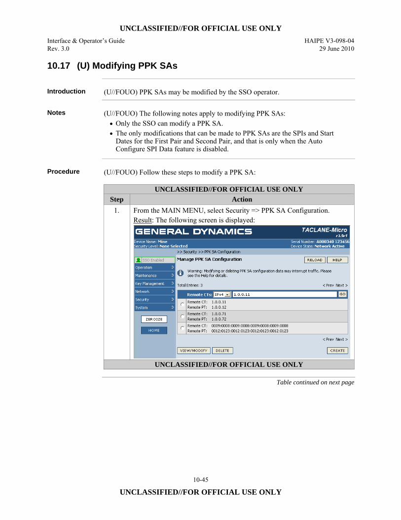
UNCLASSIFIED//FOR OFFICIAL USE ONLY Interface & Operator’s Guide HAIPE V3-098-04 Rev. 3.0 29 June 2010
10-45
UNCLASSIFIED//FOR OFFICIAL USE ONLY
10.17 (U) Modifying PPK SAs
Introduction (U//FOUO) PPK SAs may be modified by the SSO operator.
Notes (U//FOUO) The following notes apply to modifying PPK SAs:
• Only the SSO can modify a PPK SA. • The only modifications that can be made to PPK SAs are the SPIs and Start
Dates for the First Pair and Second Pair, and that is only when the Auto Configure SPI Data feature is disabled.
Procedure (U//FOUO) Follow these steps to modify a PPK SA:
UNCLASSIFIED//FOR OFFICIAL USE ONLY Step Action
1. From the MAIN MENU, select Security => PPK SA Configuration. Result: The following screen is displayed:
UNCLASSIFIED//FOR OFFICIAL USE ONLY
Table continued on next page
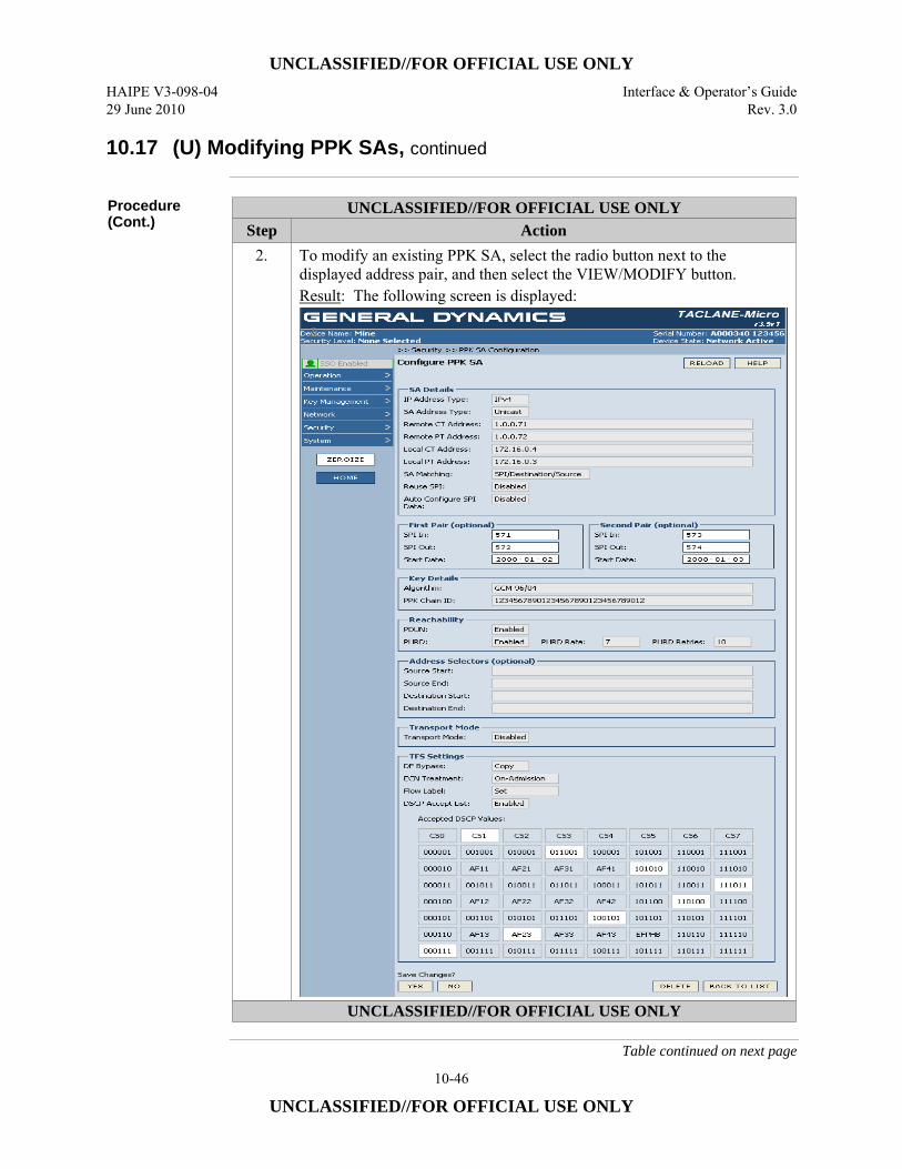
UNCLASSIFIED//FOR OFFICIAL USE ONLY HAIPE V3-098-04 Interface & Operator’s Guide 29 June 2010 Rev. 3.0
10-46
UNCLASSIFIED//FOR OFFICIAL USE ONLY
10.17 (U) Modifying PPK SAs, continued
Procedure (Cont.)
UNCLASSIFIED//FOR OFFICIAL USE ONLY Step Action
2. To modify an existing PPK SA, select the radio button next to the displayed address pair, and then select the VIEW/MODIFY button. Result: The following screen is displayed:
UNCLASSIFIED//FOR OFFICIAL USE ONLY
Table continued on next page
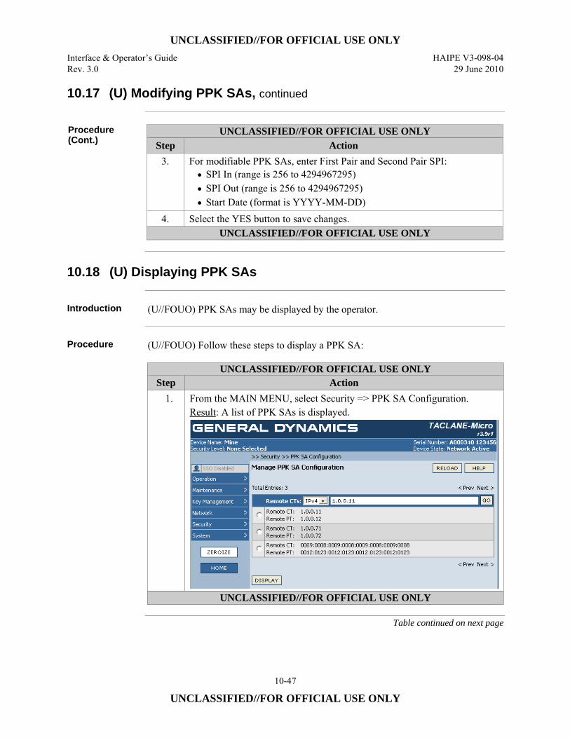
UNCLASSIFIED//FOR OFFICIAL USE ONLY Interface & Operator’s Guide HAIPE V3-098-04 Rev. 3.0 29 June 2010
10-47
UNCLASSIFIED//FOR OFFICIAL USE ONLY
10.17 (U) Modifying PPK SAs, continued
Procedure (Cont.)
UNCLASSIFIED//FOR OFFICIAL USE ONLY Step Action
3. For modifiable PPK SAs, enter First Pair and Second Pair SPI: • SPI In (range is 256 to 4294967295) • SPI Out (range is 256 to 4294967295) • Start Date (format is YYYY-MM-DD)
4. Select the YES button to save changes. UNCLASSIFIED//FOR OFFICIAL USE ONLY
10.18 (U) Displaying PPK SAs
Introduction (U//FOUO) PPK SAs may be displayed by the operator.
Procedure (U//FOUO) Follow these steps to display a PPK SA:
UNCLASSIFIED//FOR OFFICIAL USE ONLY Step Action
1. From the MAIN MENU, select Security => PPK SA Configuration. Result: A list of PPK SAs is displayed.
UNCLASSIFIED//FOR OFFICIAL USE ONLY
Table continued on next page
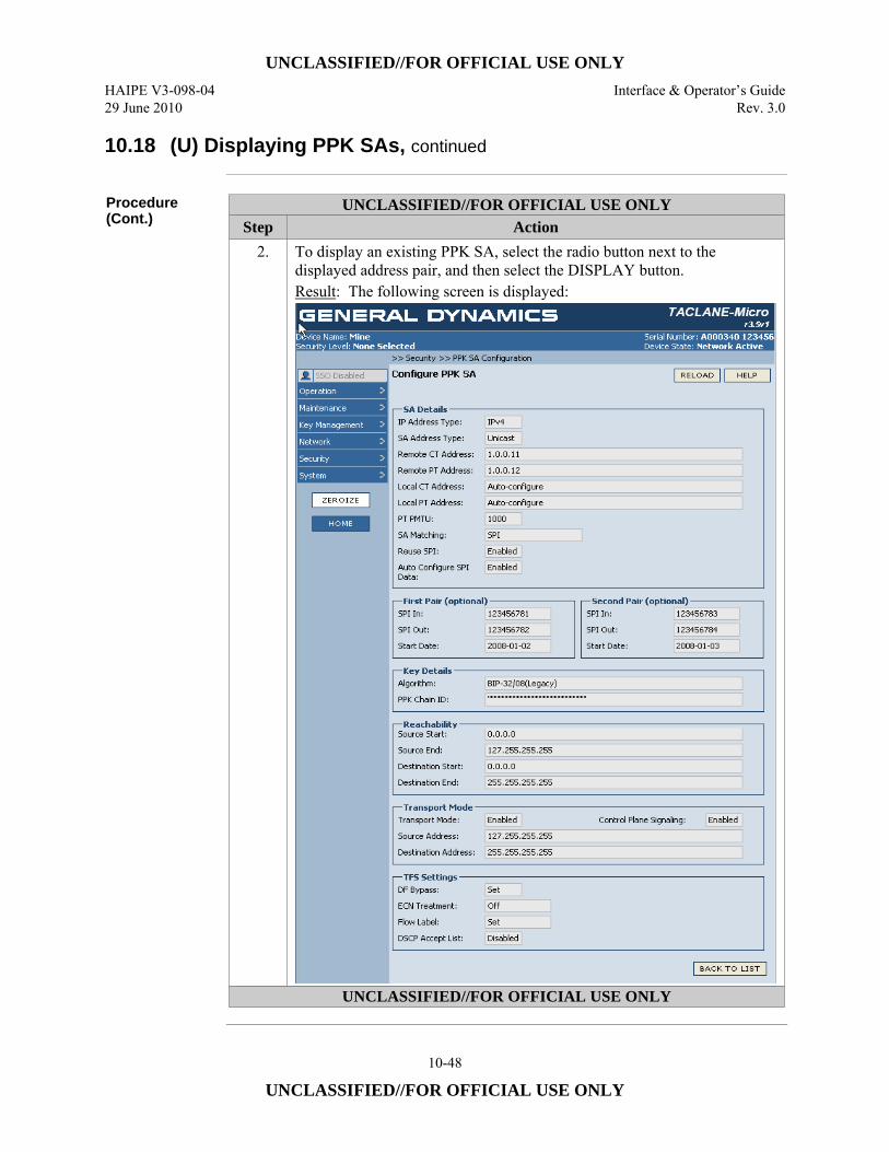
UNCLASSIFIED//FOR OFFICIAL USE ONLY HAIPE V3-098-04 Interface & Operator’s Guide 29 June 2010 Rev. 3.0
10-48
UNCLASSIFIED//FOR OFFICIAL USE ONLY
10.18 (U) Displaying PPK SAs, continued
Procedure (Cont.)
UNCLASSIFIED//FOR OFFICIAL USE ONLY Step Action
2. To display an existing PPK SA, select the radio button next to the displayed address pair, and then select the DISPLAY button. Result: The following screen is displayed:
UNCLASSIFIED//FOR OFFICIAL USE ONLY
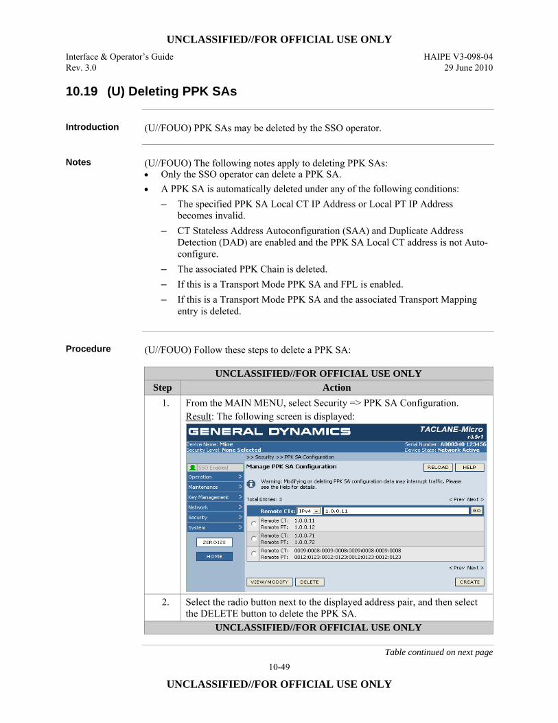
UNCLASSIFIED//FOR OFFICIAL USE ONLY Interface & Operator’s Guide HAIPE V3-098-04 Rev. 3.0 29 June 2010
10-49
UNCLASSIFIED//FOR OFFICIAL USE ONLY
10.19 (U) Deleting PPK SAs
Introduction (U//FOUO) PPK SAs may be deleted by the SSO operator.
Notes (U//FOUO) The following notes apply to deleting PPK SAs:
• Only the SSO operator can delete a PPK SA. • A PPK SA is automatically deleted under any of the following conditions:
– The specified PPK SA Local CT IP Address or Local PT IP Address becomes invalid.
– CT Stateless Address Autoconfiguration (SAA) and Duplicate Address Detection (DAD) are enabled and the PPK SA Local CT address is not Auto-configure.
– The associated PPK Chain is deleted. – If this is a Transport Mode PPK SA and FPL is enabled. – If this is a Transport Mode PPK SA and the associated Transport Mapping
entry is deleted.
Procedure (U//FOUO) Follow these steps to delete a PPK SA:
UNCLASSIFIED//FOR OFFICIAL USE ONLY Step Action
1. From the MAIN MENU, select Security => PPK SA Configuration. Result: The following screen is displayed:
2. Select the radio button next to the displayed address pair, and then select the DELETE button to delete the PPK SA.
UNCLASSIFIED//FOR OFFICIAL USE ONLY
Table continued on next page
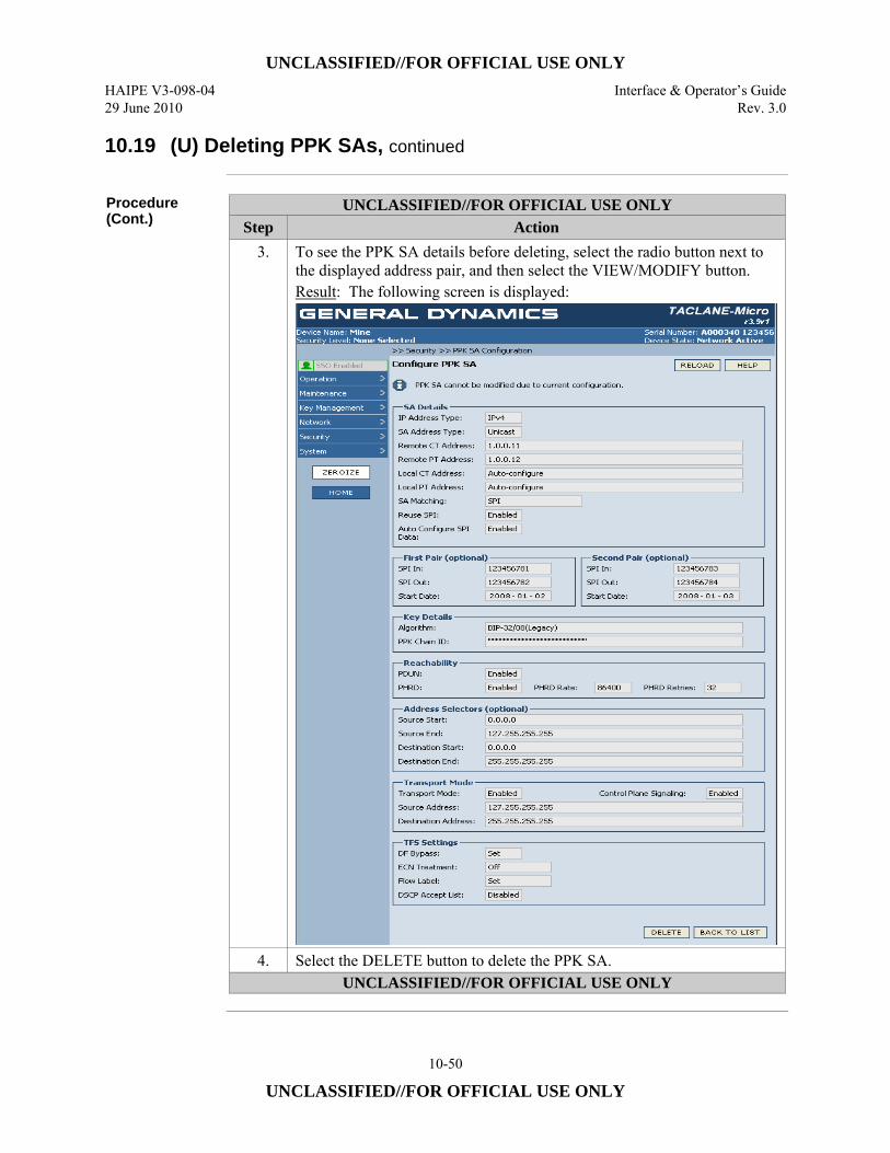
UNCLASSIFIED//FOR OFFICIAL USE ONLY HAIPE V3-098-04 Interface & Operator’s Guide 29 June 2010 Rev. 3.0
10-50
UNCLASSIFIED//FOR OFFICIAL USE ONLY
10.19 (U) Deleting PPK SAs, continued
Procedure (Cont.)
UNCLASSIFIED//FOR OFFICIAL USE ONLY Step Action
3. To see the PPK SA details before deleting, select the radio button next to the displayed address pair, and then select the VIEW/MODIFY button. Result: The following screen is displayed:
4. Select the DELETE button to delete the PPK SA. UNCLASSIFIED//FOR OFFICIAL USE ONLY
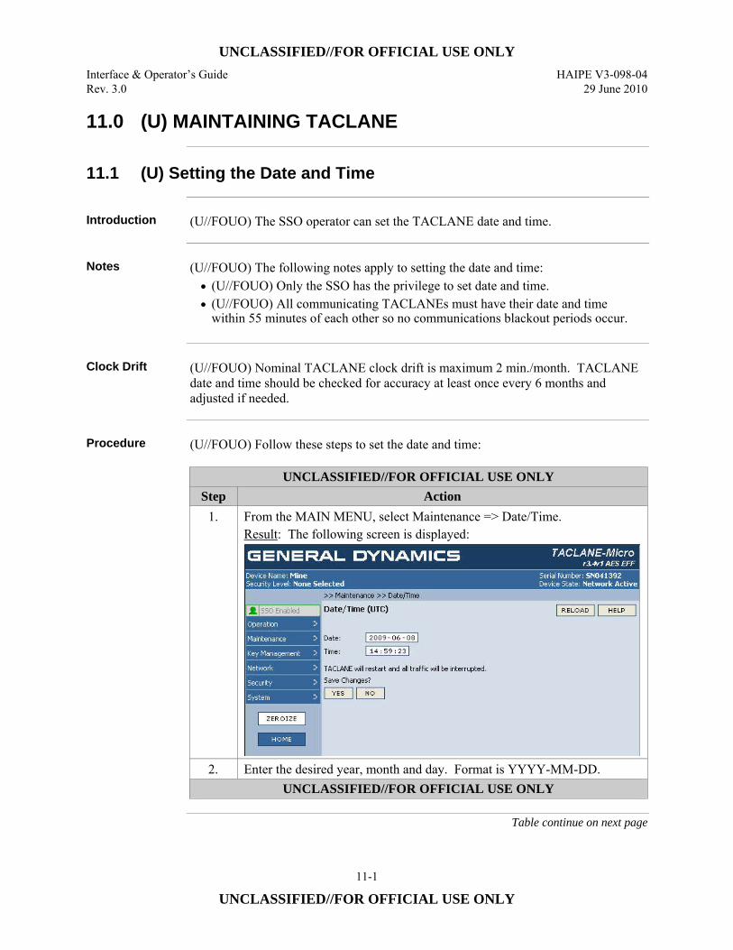
UNCLASSIFIED//FOR OFFICIAL USE ONLY Interface & Operator’s Guide HAIPE V3-098-04 Rev. 3.0 29 June 2010
11-1
UNCLASSIFIED//FOR OFFICIAL USE ONLY
11.0 (U) MAINTAINING TACLANE
11.1 (U) Setting the Date and Time
Introduction (U//FOUO) The SSO operator can set the TACLANE date and time.
Notes (U//FOUO) The following notes apply to setting the date and time:
• (U//FOUO) Only the SSO has the privilege to set date and time. • (U//FOUO) All communicating TACLANEs must have their date and time
within 55 minutes of each other so no communications blackout periods occur.
Clock Drift (U//FOUO) Nominal TACLANE clock drift is maximum 2 min./month. TACLANE
date and time should be checked for accuracy at least once every 6 months and adjusted if needed.
Procedure (U//FOUO) Follow these steps to set the date and time:
UNCLASSIFIED//FOR OFFICIAL USE ONLY Step Action
1. From the MAIN MENU, select Maintenance => Date/Time. Result: The following screen is displayed:
2. Enter the desired year, month and day. Format is YYYY-MM-DD. UNCLASSIFIED//FOR OFFICIAL USE ONLY
Table continue on next page
UNCLASSIFIED//FOR OFFICIAL USE ONLY HAIPE V3-098-04 Interface & Operator’s Guide 29 June 2010 Rev. 3.0
11-2
UNCLASSIFIED//FOR OFFICIAL USE ONLY
11.1 (U) Setting the Date and Time, continued
Procedure (Cont.)
UNCLASSIFIED//FOR OFFICIAL USE ONLY Step Action
3. Enter the desired hour, minute and seconds. Format is hh:mm:ss. Note: Changing the time ahead may expire and automatically delete PPKs. Changing the time backwards may cause a PPK to not be used until the date catches up with the PPK’s update count.
4. Select the YES button to save changes. Note: This will cause the TACLANE to restart.
UNCLASSIFIED//FOR OFFICIAL USE ONLY
11.2 (U) Creating a CIK
Introduction (U//FOUO) The SSO operator can use the Create CIK function to create up to two
additional CIKs. A CIK (Crypto Ignition Key) is used to unlock wrapped key stored within the TACLANE. A TACLANE shipped from the factory comes with one valid user CIK (shipped separately) as well as one KSD (a blank CIK).
Create CIK (Make a Copy)
(U//FOUO) A KSD (a blank CIK) is included with the TACLANE. General Dynamics recommends that the SSO operator use this KSD to create a second user CIK. One CIK should be tagged and kept in a safe place. The other CIK should then be used for normal TACLANE operation.
Important CIK Notes
(U//FOUO) The CIK snaps into place when inserted. It is recommended that the CIK not have excess weight, such as a key ring, connected to it when installed. (U//FOUO)Additional KSDs, General Dynamics C4 Systems part number MC-101A, are available through TACLANE Sales Support. Contact information is provided in Section 1.7 of this manual.
Continue on next page
UNCLASSIFIED//FOR OFFICIAL USE ONLY Interface & Operator’s Guide HAIPE V3-098-04 Rev. 3.0 29 June 2010
11-3
UNCLASSIFIED//FOR OFFICIAL USE ONLY
11.2 (U) Creating a CIK, continued
Notes (U//FOUO) The following notes apply to creating a CIK:
• (U//FOUO) Only the SSO has the privilege to create a CIK. • (U//FOUO) Up to two additional CIKs may be created (three total). • (U//FOUO) CIKs already associated with this TACLANE will be detected, so
that they will not be destroyed. Warning: CIKs associated with other TACLANEs will be overwritten if used to create a CIK.
• (U//FOUO) The operator has five minutes to complete the CIK creation. If the CIK creation is not completed within five minutes, the TACLANE resets automatically.
• (U//FOUO) Removing the active CIK at anytime other than during CIK creation causes the TACLANE to restart.
• (U//FOUO) A CIK Failed audit log entry with a reason of “Error Reading from CIK” could indicate an invalid CIK was detected.
Canceling CIK Create
(U//FOUO) If CIK creation is cancelled, a grace period for completing the operation will continue in order to permit the SSO time to insert the original CIK. If the grace period expires, the TACLANE will restart. If the original CIK is inserted, the grace period is terminated and subsequent removal of the CIK causes the TACLANE to restart. (U//FOUO) Warning: SSO privileges are still enabled after canceling the CIK create.
Continued on next page
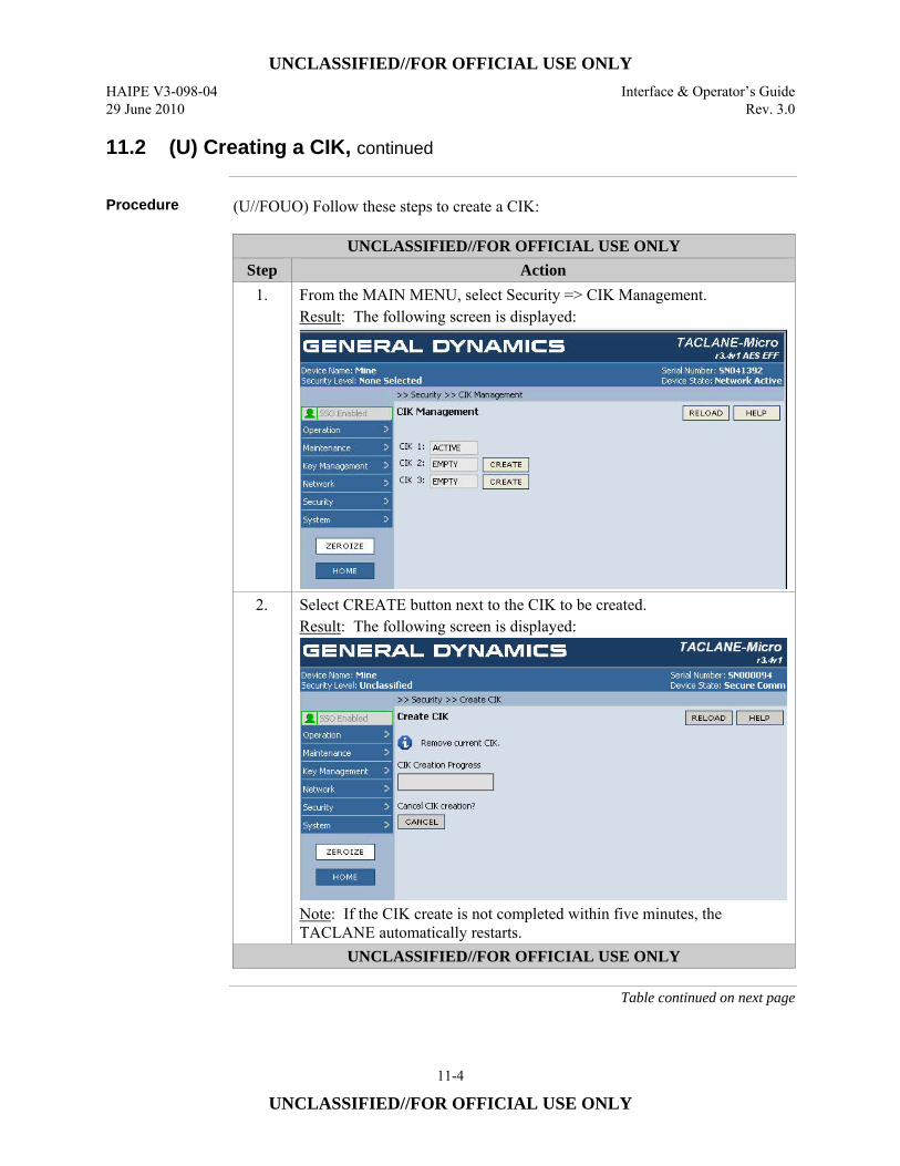
UNCLASSIFIED//FOR OFFICIAL USE ONLY HAIPE V3-098-04 Interface & Operator’s Guide 29 June 2010 Rev. 3.0
11-4
UNCLASSIFIED//FOR OFFICIAL USE ONLY
11.2 (U) Creating a CIK, continued
Procedure (U//FOUO) Follow these steps to create a CIK:
UNCLASSIFIED//FOR OFFICIAL USE ONLY Step Action
1. From the MAIN MENU, select Security => CIK Management. Result: The following screen is displayed:
2. Select CREATE button next to the CIK to be created. Result: The following screen is displayed:
Note: If the CIK create is not completed within five minutes, the TACLANE automatically restarts.
UNCLASSIFIED//FOR OFFICIAL USE ONLY
Table continued on next page
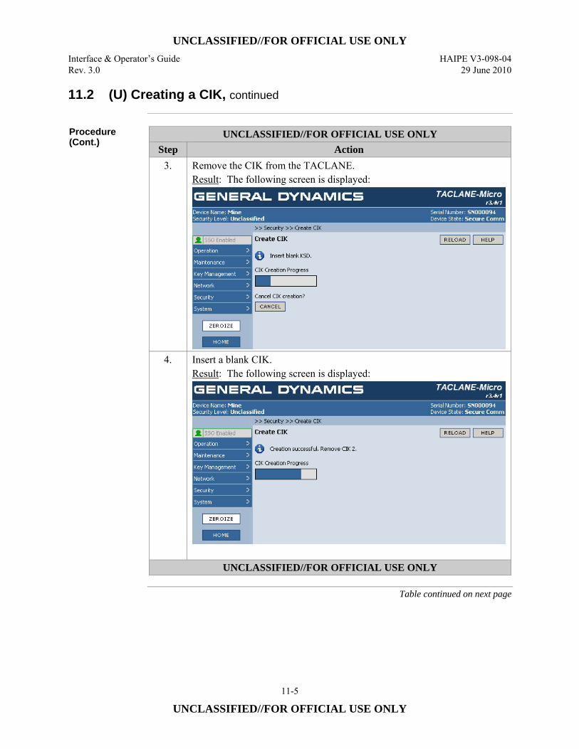
UNCLASSIFIED//FOR OFFICIAL USE ONLY Interface & Operator’s Guide HAIPE V3-098-04 Rev. 3.0 29 June 2010
11-5
UNCLASSIFIED//FOR OFFICIAL USE ONLY
11.2 (U) Creating a CIK, continued
Procedure (Cont.)
UNCLASSIFIED//FOR OFFICIAL USE ONLY Step Action
3. Remove the CIK from the TACLANE. Result: The following screen is displayed:
4. Insert a blank CIK. Result: The following screen is displayed:
UNCLASSIFIED//FOR OFFICIAL USE ONLY
Table continued on next page
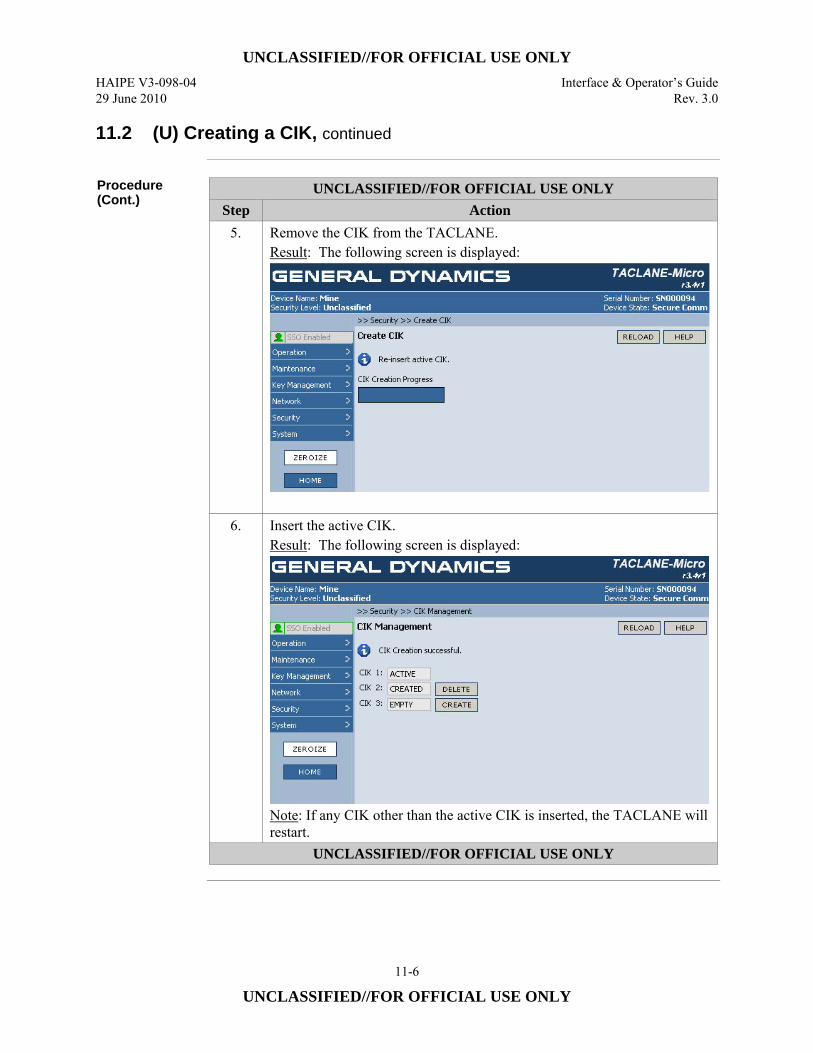
UNCLASSIFIED//FOR OFFICIAL USE ONLY HAIPE V3-098-04 Interface & Operator’s Guide 29 June 2010 Rev. 3.0
11-6
UNCLASSIFIED//FOR OFFICIAL USE ONLY
11.2 (U) Creating a CIK, continued
Procedure (Cont.)
UNCLASSIFIED//FOR OFFICIAL USE ONLY Step Action
5. Remove the CIK from the TACLANE. Result: The following screen is displayed:
6. Insert the active CIK. Result: The following screen is displayed:
Note: If any CIK other than the active CIK is inserted, the TACLANE will restart.
UNCLASSIFIED//FOR OFFICIAL USE ONLY
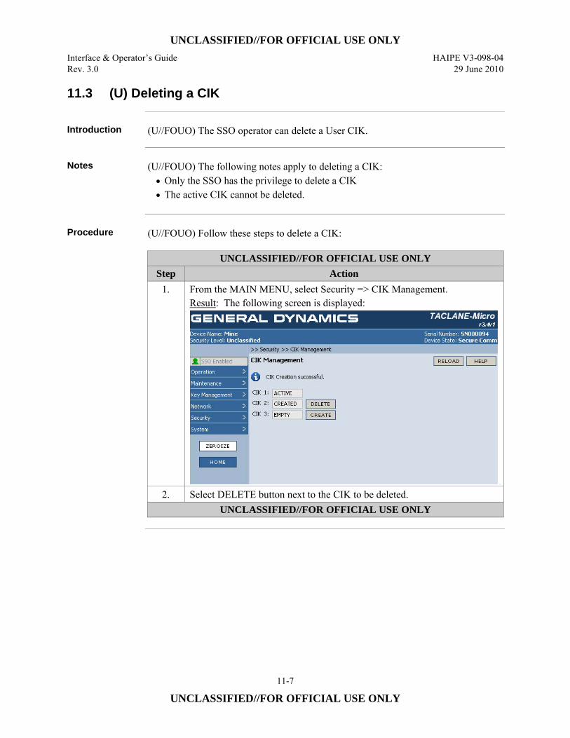
UNCLASSIFIED//FOR OFFICIAL USE ONLY Interface & Operator’s Guide HAIPE V3-098-04 Rev. 3.0 29 June 2010
11-7
UNCLASSIFIED//FOR OFFICIAL USE ONLY
11.3 (U) Deleting a CIK
Introduction (U//FOUO) The SSO operator can delete a User CIK.
Notes (U//FOUO) The following notes apply to deleting a CIK:
• Only the SSO has the privilege to delete a CIK • The active CIK cannot be deleted.
Procedure (U//FOUO) Follow these steps to delete a CIK:
UNCLASSIFIED//FOR OFFICIAL USE ONLY Step Action
1. From the MAIN MENU, select Security => CIK Management. Result: The following screen is displayed:
2. Select DELETE button next to the CIK to be deleted. UNCLASSIFIED//FOR OFFICIAL USE ONLY
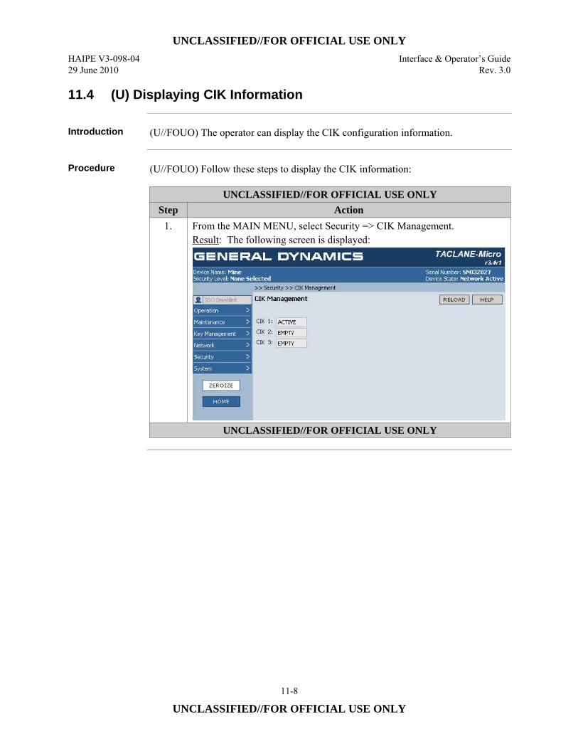
UNCLASSIFIED//FOR OFFICIAL USE ONLY HAIPE V3-098-04 Interface & Operator’s Guide 29 June 2010 Rev. 3.0
11-8
UNCLASSIFIED//FOR OFFICIAL USE ONLY
11.4 (U) Displaying CIK Information
Introduction (U//FOUO) The operator can display the CIK configuration information.
Procedure (U//FOUO) Follow these steps to display the CIK information:
UNCLASSIFIED//FOR OFFICIAL USE ONLY Step Action
1. From the MAIN MENU, select Security => CIK Management. Result: The following screen is displayed:
UNCLASSIFIED//FOR OFFICIAL USE ONLY
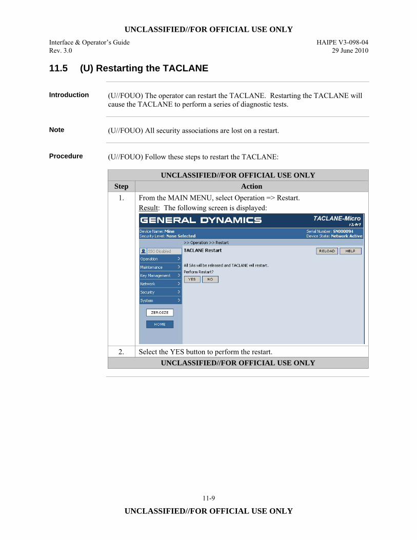
UNCLASSIFIED//FOR OFFICIAL USE ONLY Interface & Operator’s Guide HAIPE V3-098-04 Rev. 3.0 29 June 2010
11-9
UNCLASSIFIED//FOR OFFICIAL USE ONLY
11.5 (U) Restarting the TACLANE
Introduction (U//FOUO) The operator can restart the TACLANE. Restarting the TACLANE will
cause the TACLANE to perform a series of diagnostic tests.
Note (U//FOUO) All security associations are lost on a restart.
Procedure (U//FOUO) Follow these steps to restart the TACLANE:
UNCLASSIFIED//FOR OFFICIAL USE ONLY Step Action
1. From the MAIN MENU, select Operation => Restart. Result: The following screen is displayed:
2. Select the YES button to perform the restart. UNCLASSIFIED//FOR OFFICIAL USE ONLY
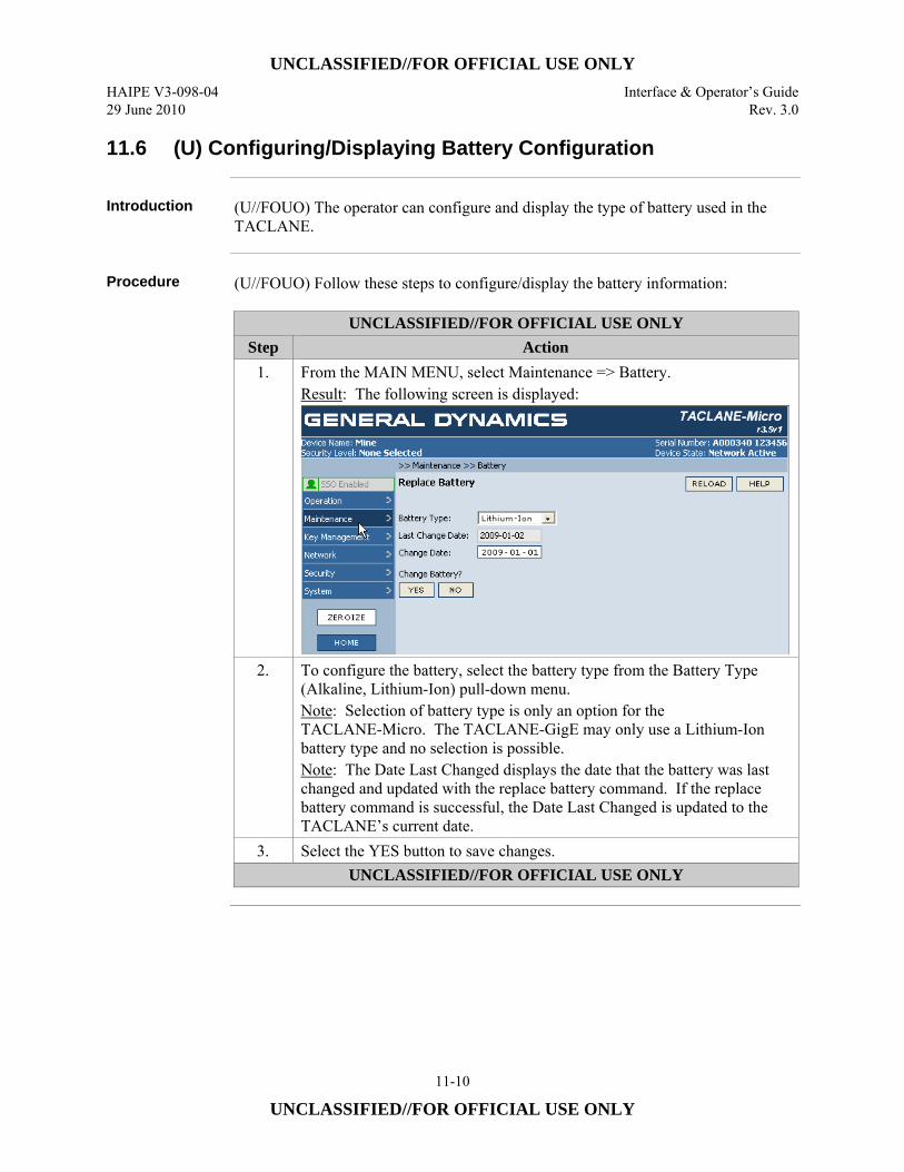
UNCLASSIFIED//FOR OFFICIAL USE ONLY HAIPE V3-098-04 Interface & Operator’s Guide 29 June 2010 Rev. 3.0
11-10
UNCLASSIFIED//FOR OFFICIAL USE ONLY
11.6 (U) Configuring/Displaying Battery Configuration
Introduction (U//FOUO) The operator can configure and display the type of battery used in the
TACLANE.
Procedure (U//FOUO) Follow these steps to configure/display the battery information:
UNCLASSIFIED//FOR OFFICIAL USE ONLY Step Action
1. From the MAIN MENU, select Maintenance => Battery. Result: The following screen is displayed:
2. To configure the battery, select the battery type from the Battery Type (Alkaline, Lithium-Ion) pull-down menu. Note: Selection of battery type is only an option for the TACLANE-Micro. The TACLANE-GigE may only use a Lithium-Ion battery type and no selection is possible. Note: The Date Last Changed displays the date that the battery was last changed and updated with the replace battery command. If the replace battery command is successful, the Date Last Changed is updated to the TACLANE’s current date.
3. Select the YES button to save changes. UNCLASSIFIED//FOR OFFICIAL USE ONLY
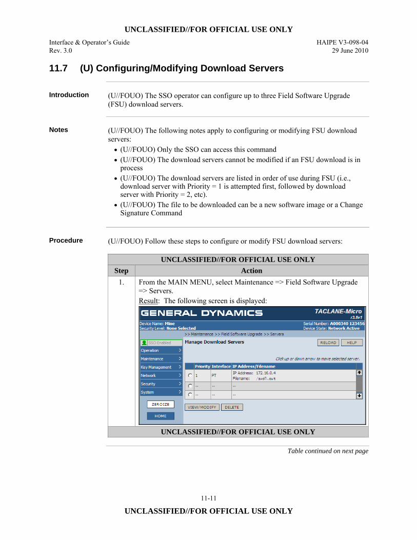
UNCLASSIFIED//FOR OFFICIAL USE ONLY Interface & Operator’s Guide HAIPE V3-098-04 Rev. 3.0 29 June 2010
11-11
UNCLASSIFIED//FOR OFFICIAL USE ONLY
11.7 (U) Configuring/Modifying Download Servers
Introduction (U//FOUO) The SSO operator can configure up to three Field Software Upgrade
(FSU) download servers.
Notes (U//FOUO) The following notes apply to configuring or modifying FSU download
servers: • (U//FOUO) Only the SSO can access this command • (U//FOUO) The download servers cannot be modified if an FSU download is in
process • (U//FOUO) The download servers are listed in order of use during FSU (i.e.,
download server with Priority = 1 is attempted first, followed by download server with Priority = 2, etc).
• (U//FOUO) The file to be downloaded can be a new software image or a Change Signature Command
Procedure (U//FOUO) Follow these steps to configure or modify FSU download servers:
UNCLASSIFIED//FOR OFFICIAL USE ONLY Step Action
1. From the MAIN MENU, select Maintenance => Field Software Upgrade => Servers. Result: The following screen is displayed:
UNCLASSIFIED//FOR OFFICIAL USE ONLY
Table continued on next page

UNCLASSIFIED//FOR OFFICIAL USE ONLY HAIPE V3-098-04 Interface & Operator’s Guide 29 June 2010 Rev. 3.0
11-12
UNCLASSIFIED//FOR OFFICIAL USE ONLY
11.7 (U) Configuring/Modifying Download Servers, continued
Procedure (Cont.)
UNCLASSIFIED//FOR OFFICIAL USE ONLY Step Action
2. Select the radio button next to a row in the displayed table and then click the up (↑) or down (↓) arrow on the right-hand side of the table to modify the Priority of the selected row. The up arrow (↑) increases the priority of the selected row and the down arrow (↓) decreases the priority of the selected row. The rows in the displayed table are ordered from highest priority first choice (1) at the top of the table to lowest priority last choice (3) at the bottom of the table.
3. Select a radio button next to a defined download server to modify it or an undefined row to configure a new server. Select VIEW/MODIFY button to create or modify the FSU download server configuration. Note: Selection of the row defines the Priority displayed in the next screen. Result: The following screen is displayed:
4. Select the radio button corresponding to the Interface (i.e., PT, CT, or Console) over which the software upgrade file will be downloaded.
5. Select the radio button corresponding to the IP address type (i.e., IPv4 or IPv6) for the interface. The IP Address Type must be IPv4, if the Console Interface was selected.
6. Enter the IP Address of the download server UNCLASSIFIED//FOR OFFICIAL USE ONLY
Table continued on next page
UNCLASSIFIED//FOR OFFICIAL USE ONLY Interface & Operator’s Guide HAIPE V3-098-04 Rev. 3.0 29 June 2010
11-13
UNCLASSIFIED//FOR OFFICIAL USE ONLY
11.7 (U) Configuring/Modifying Download Servers, continued
Procedure (Cont.)
UNCLASSIFIED//FOR OFFICIAL USE ONLY Step Action
7. Enter the Filename of the FSU file on the download server (including any path information). Note: The filename must begin with the “/” character. It must not include any of the following characters:
% - percent sign & - ampersand ′ - single quote ( - open parenthesis ) - close parenthesis * - asterisk , - comma < - open angle bracket = - equal sign > - close angle bracket @ - at symbol [ - open bracket ] - close bracket ^ - caret circumflex { - open brace } - close brace
The total number of characters in the IP Address together with the filename (including the leading “/”) must be 248 or less.
8. Select the YES button to save changes. UNCLASSIFIED//FOR OFFICIAL USE ONLY
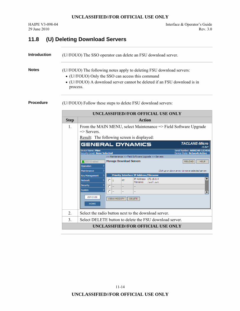
UNCLASSIFIED//FOR OFFICIAL USE ONLY HAIPE V3-098-04 Interface & Operator’s Guide 29 June 2010 Rev. 3.0
11-14
UNCLASSIFIED//FOR OFFICIAL USE ONLY
11.8 (U) Deleting Download Servers
Introduction (U//FOUO) The SSO operator can delete an FSU download server.
Notes (U//FOUO) The following notes apply to deleting FSU download servers:
• (U//FOUO) Only the SSO can access this command • (U//FOUO) A download server cannot be deleted if an FSU download is in
process.
Procedure (U//FOUO) Follow these steps to delete FSU download servers:
UNCLASSIFIED//FOR OFFICIAL USE ONLY Step Action
1. From the MAIN MENU, select Maintenance => Field Software Upgrade => Servers. Result: The following screen is displayed:
2. Select the radio button next to the download server. 3. Select DELETE button to delete the FSU download server.
UNCLASSIFIED//FOR OFFICIAL USE ONLY
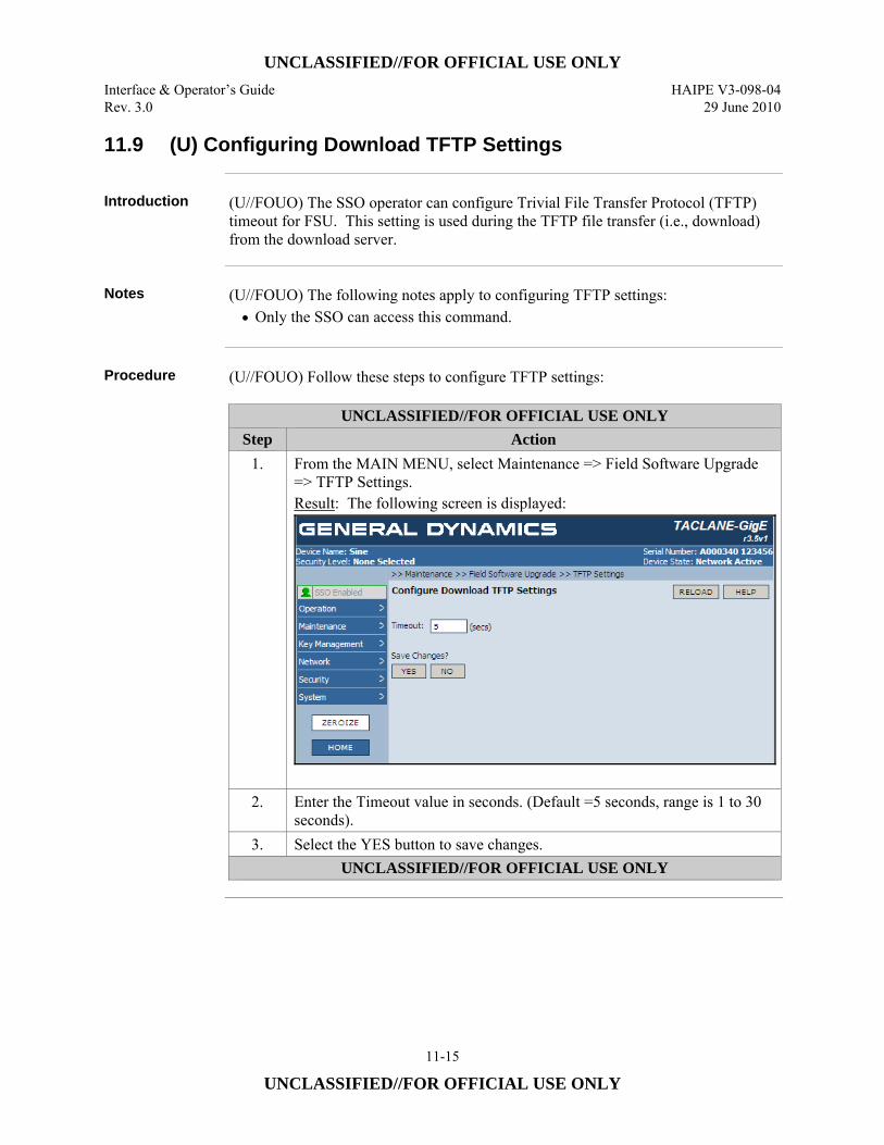
UNCLASSIFIED//FOR OFFICIAL USE ONLY Interface & Operator’s Guide HAIPE V3-098-04 Rev. 3.0 29 June 2010
11-15
UNCLASSIFIED//FOR OFFICIAL USE ONLY
11.9 (U) Configuring Download TFTP Settings
Introduction (U//FOUO) The SSO operator can configure Trivial File Transfer Protocol (TFTP)
timeout for FSU. This setting is used during the TFTP file transfer (i.e., download) from the download server.
Notes (U//FOUO) The following notes apply to configuring TFTP settings:
• Only the SSO can access this command.
Procedure (U//FOUO) Follow these steps to configure TFTP settings:
UNCLASSIFIED//FOR OFFICIAL USE ONLY Step Action
1. From the MAIN MENU, select Maintenance => Field Software Upgrade => TFTP Settings. Result: The following screen is displayed:
2. Enter the Timeout value in seconds. (Default =5 seconds, range is 1 to 30
seconds). 3. Select the YES button to save changes.
UNCLASSIFIED//FOR OFFICIAL USE ONLY
UNCLASSIFIED//FOR OFFICIAL USE ONLY HAIPE V3-098-04 Interface & Operator’s Guide 29 June 2010 Rev. 3.0
11-16
UNCLASSIFIED//FOR OFFICIAL USE ONLY
11.10 (U) Downloading an FSU File
Introduction (U//FOUO) The operator can download an FSU file via the PT, CT, or Console
interface to load a new software release or new Software Signature into the TACLANE. The interface on which the file is downloaded is determined by the download server configuration.
Notes (U//FOUO) The following notes apply to performing an FSU download:
• (U//FOUO) Only the SSO can access this command. • (U//FOUO) A stable power environment must be maintained throughout the
procedure. Use of an uninterruptible power supply (UPS) is recommended. • (U//FOUO) The file to be downloaded can be a new software image or a Change
Signature Command. • (U//FOUO) Path information included in the filename field will be ignored. • (U//FOUO) The base directory on the TFTP server must be set to the directory
where the FSU file resides because this is where the TACLANE will look for it.
Major and Minor Releases
(U//FOUO) The version of TACLANE software being loaded cannot digress beyond a previous major release, because it will not be compatible. Major releases must be upgraded consecutively and cannot be skipped. Minor releases can be skipped and overwritten with earlier minor releases in the same major release. (U//FOUO) General Dynamics identifies TACLANE software releases as major or minor in the release notes accompanying the software. (U//FOUO) For the TACLANE-Micro product, Version 3.3 was the initial major release of the software. Version 3.3 supported HAIPE IS v1.3.5 compliant IP encryption. Micro Version 3.4 is a major release that supports HAIPE IS v3.0.2. Version 3.5, described in this manual, is a major release. It supports HAIPE IS v3.1.2 compliant IP encryption. (U//FOUO) For the TACLANE-GigE product Version 3.1 was the first major operational software release. Version 3.1 supported HAIPE IS v1.3.5 compliant IP encryption. Version 3.2 was the second major release of the GigE programmable image. It is HAIPE IS v1.3.5 compliant and supports BATON and MEDLEY traffic encryption. Version 3.5, described in this manual, is the newest major release of the GigE software. It supports HAIPE IS v3.1.2 compliant IP encryption. (U//FOUO) Note: Image decryption will fail for a release that is not permitted as an upgrade to a currently installed TACLANE software release.
Continued on next page
UNCLASSIFIED//FOR OFFICIAL USE ONLY Interface & Operator’s Guide HAIPE V3-098-04 Rev. 3.0 29 June 2010
11-17
UNCLASSIFIED//FOR OFFICIAL USE ONLY
11.10 (U) Downloading an FSU File, continued
Requirements (U//FOUO) Before beginning an FSU download, make sure that you have the
following: • (U//FOUO) A configured FSU download server containing the FSU file to be
downloaded • (U//FOUO) TFTP server configured and running on the download server.
TFTP File Server Settings
(U//FOUO) Before beginning an FSU download, the TFTP server on the download server that will be used for the download must be configured and running. • TFTP Port: 69 • Base Directory: location of FSU file on server • Server Interface: IP address of server.
Tip (U//FOUO) If an error occurs during the procedure, such as a tamper condition or
continuous alarm state, Field Tamper Recovery may be used to reset the unit and generate a new User CIK. See, “Performing a Field Tamper Recovery” for instructions. Then return to this section and retry the Field Software Upgrade.
Continued on next page
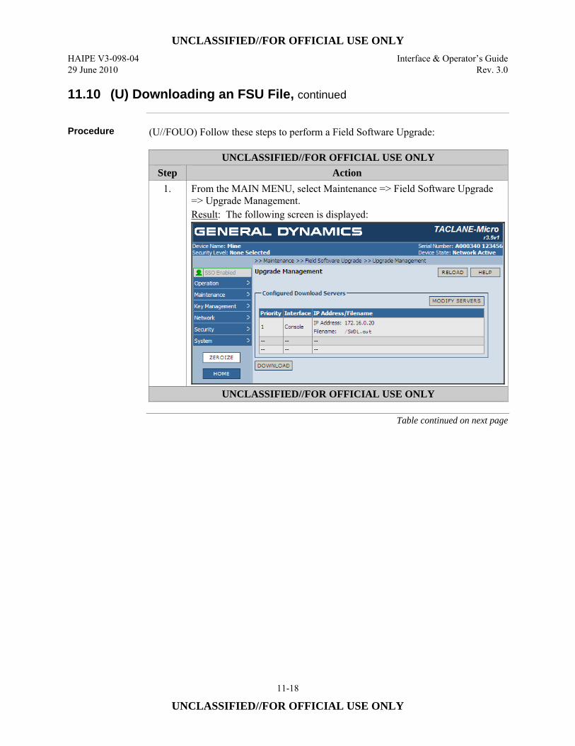
UNCLASSIFIED//FOR OFFICIAL USE ONLY HAIPE V3-098-04 Interface & Operator’s Guide 29 June 2010 Rev. 3.0
11-18
UNCLASSIFIED//FOR OFFICIAL USE ONLY
11.10 (U) Downloading an FSU File, continued
Procedure (U//FOUO) Follow these steps to perform a Field Software Upgrade:
UNCLASSIFIED//FOR OFFICIAL USE ONLY Step Action
1. From the MAIN MENU, select Maintenance => Field Software Upgrade => Upgrade Management. Result: The following screen is displayed:
UNCLASSIFIED//FOR OFFICIAL USE ONLY
Table continued on next page
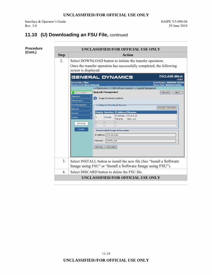
UNCLASSIFIED//FOR OFFICIAL USE ONLY Interface & Operator’s Guide HAIPE V3-098-04 Rev. 3.0 29 June 2010
11-19
UNCLASSIFIED//FOR OFFICIAL USE ONLY
11.10 (U) Downloading an FSU File, continued
Procedure (Cont.)
UNCLASSIFIED//FOR OFFICIAL USE ONLY Step Action
2. Select DOWNLOAD button to initiate the transfer operation. Once the transfer operation has successfully completed, the following screen is displayed:
3. Select INSTALL button to install the new file (See “Install a Software Image using FSU” or “Install a Software Image using FSU”).
4. Select DISCARD button to delete the FSU file. UNCLASSIFIED//FOR OFFICIAL USE ONLY
UNCLASSIFIED//FOR OFFICIAL USE ONLY HAIPE V3-098-04 Interface & Operator’s Guide 29 June 2010 Rev. 3.0
11-20
UNCLASSIFIED//FOR OFFICIAL USE ONLY
11.11 (U) Installing a Software Image using FSU
Introduction (U//FOUO) The operator can install a new software release (a previously transferred
FSU file) into the TACLANE.
Notes (U//FOUO) The following notes apply to performing an install FSU:
• (U//FOUO) Only the SSO can access this command. • (U//FOUO) The install process can take four minutes to write the image to flash. • (U//FOUO) If the installation process is interrupted, the TACLANE will
continue to use the previous image. FSU will not complete and will need to be redone.
Major and Minor Releases
(U//FOUO) The version of TACLANE software being loaded cannot digress beyond a previous major release, because it will not be compatible. Major releases must be upgraded consecutively and cannot be skipped. Minor releases can be skipped and overwritten with earlier minor releases in the same major release. (U//FOUO) General Dynamics identifies TACLANE software releases as major or minor in the release notes accompanying the software. (U//FOUO) For the TACLANE-Micro product, Version 3.3 was the initial major release of the software. Version 3.3 supported HAIPE IS v1.3.5 compliant IP encryption. Micro Version 3.4 is a major release that supports HAIPE IS v3.0.2. Version 3.5, described in this manual, is a major release. It supports HAIPE IS v3.1.2 compliant IP encryption. (U//FOUO) For the TACLANE-GigE product Version 3.1 was the first major operational software release. Version 3.1 supported HAIPE IS v1.3.5 compliant IP encryption. Version 3.2 was the second major release of the GigE programmable image. It is HAIPE IS v1.3.5 compliant and supports BATON and MEDLEY traffic encryption. Version 3.5, described in this manual, is the newest major release of the GigE software. It supports HAIPE IS v3.1.2 compliant IP encryption. (U//FOUO) Note: Image decryption will fail for a release that is not permitted as an upgrade to a currently installed TACLANE software release. On failure of an install the release that was in effect prior to the start of the FSU install remains in effect.
Tip (U//FOUO) If an error occurs during the procedure, such as a tamper condition or
continuous alarm state, Field Tamper Recovery may be used to reset the unit and generate a new User CIK. See “Performing a Field Tamper Recovery” for instructions. Then return to this section and retry the Field Software Upgrade.
Continued on next page
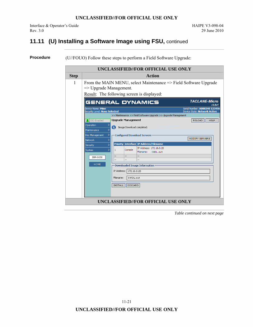
UNCLASSIFIED//FOR OFFICIAL USE ONLY Interface & Operator’s Guide HAIPE V3-098-04 Rev. 3.0 29 June 2010
11-21
UNCLASSIFIED//FOR OFFICIAL USE ONLY
11.11 (U) Installing a Software Image using FSU, continued
Procedure (U//FOUO) Follow these steps to perform a Field Software Upgrade:
UNCLASSIFIED//FOR OFFICIAL USE ONLY Step Action
1 From the MAIN MENU, select Maintenance => Field Software Upgrade => Upgrade Management. Result: The following screen is displayed:
UNCLASSIFIED//FOR OFFICIAL USE ONLY
Table continued on next page
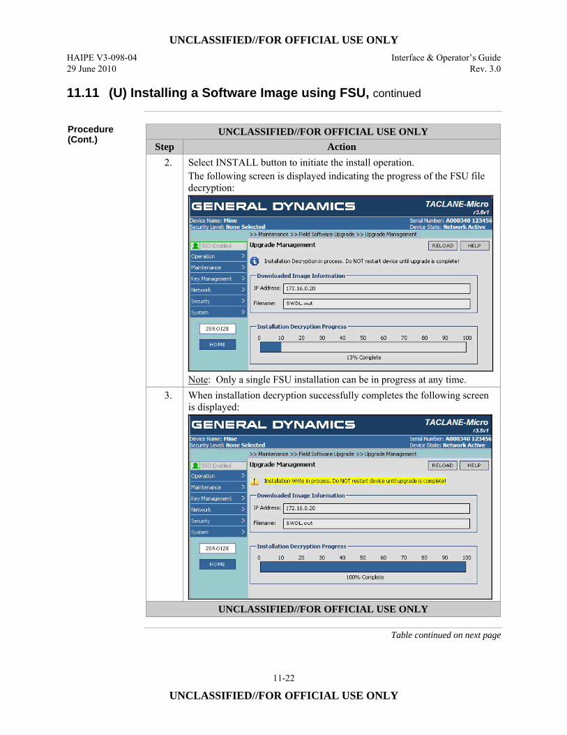
UNCLASSIFIED//FOR OFFICIAL USE ONLY HAIPE V3-098-04 Interface & Operator’s Guide 29 June 2010 Rev. 3.0
11-22
UNCLASSIFIED//FOR OFFICIAL USE ONLY
11.11 (U) Installing a Software Image using FSU, continued
Procedure (Cont.)
UNCLASSIFIED//FOR OFFICIAL USE ONLY Step Action
2. Select INSTALL button to initiate the install operation. The following screen is displayed indicating the progress of the FSU file decryption:
Note: Only a single FSU installation can be in progress at any time.
3. When installation decryption successfully completes the following screen is displayed:
UNCLASSIFIED//FOR OFFICIAL USE ONLY
Table continued on next page
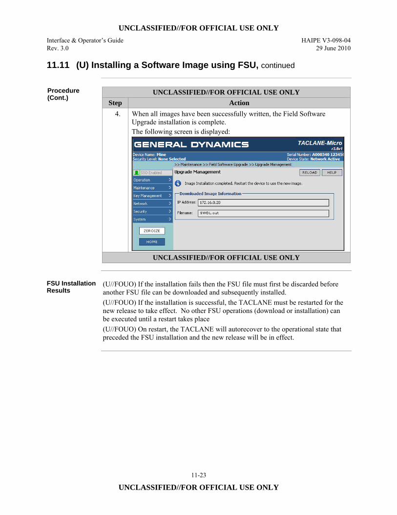
UNCLASSIFIED//FOR OFFICIAL USE ONLY Interface & Operator’s Guide HAIPE V3-098-04 Rev. 3.0 29 June 2010
11-23
UNCLASSIFIED//FOR OFFICIAL USE ONLY
11.11 (U) Installing a Software Image using FSU, continued
Procedure (Cont.)
UNCLASSIFIED//FOR OFFICIAL USE ONLY Step Action
4. When all images have been successfully written, the Field Software Upgrade installation is complete. The following screen is displayed:
UNCLASSIFIED//FOR OFFICIAL USE ONLY
FSU Installation Results
(U//FOUO) If the installation fails then the FSU file must first be discarded before another FSU file can be downloaded and subsequently installed. (U//FOUO) If the installation is successful, the TACLANE must be restarted for the new release to take effect. No other FSU operations (download or installation) can be executed until a restart takes place (U//FOUO) On restart, the TACLANE will autorecover to the operational state that preceded the FSU installation and the new release will be in effect.
UNCLASSIFIED//FOR OFFICIAL USE ONLY HAIPE V3-098-04 Interface & Operator’s Guide 29 June 2010 Rev. 3.0
11-24
UNCLASSIFIED//FOR OFFICIAL USE ONLY
11.12 (U) Installing Change Software Signature (CSC) Using FSU
Introduction (U//FOUO) The operator can install a new software signature (a previously
transferred FSU file) into the TACLANE.
Notes (U//FOUO) The following notes apply to performing an install CSC:
• (U//FOUO) Only the SSO can access this command. • (U//FOUO) If the installation process is interrupted, the TACLANE will
continue to use the previous signature. FSU will not complete and will need to be redone.
Important Restriction
(U//FOUO) Upon successfully installing a CSC, the TACLANE automatically restarts. Transitioning to Secure Communications (allowing user traffic) is blocked until a successful install of a new software image signed in the new signature occurs.
Warning (U//FOUO) Make sure the new Software Image (signed in this CSC) is available
before starting this procedure. An install of the new Software Image is required after successfully installing a CSC.
Continued on next page
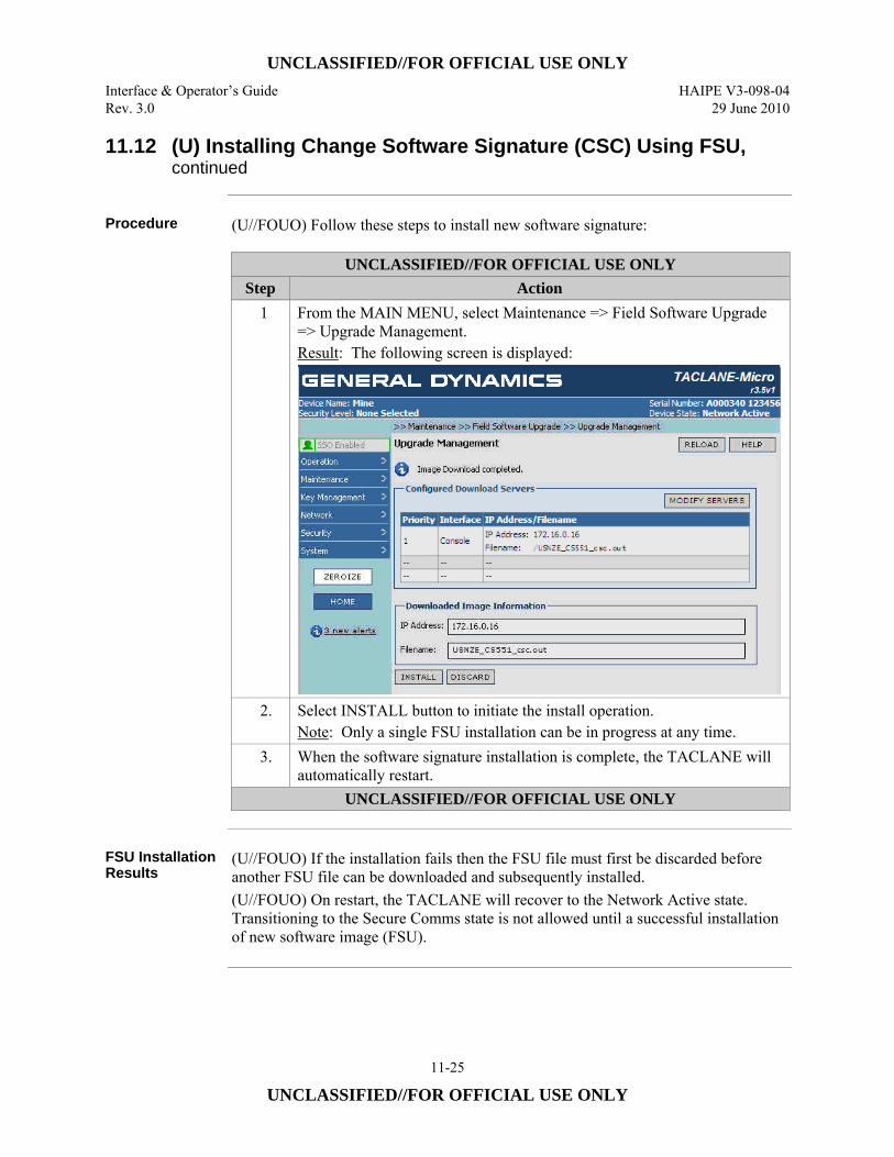
UNCLASSIFIED//FOR OFFICIAL USE ONLY Interface & Operator’s Guide HAIPE V3-098-04 Rev. 3.0 29 June 2010
11-25
UNCLASSIFIED//FOR OFFICIAL USE ONLY
11.12 (U) Installing Change Software Signature (CSC) Using FSU, continued
Procedure (U//FOUO) Follow these steps to install new software signature:
UNCLASSIFIED//FOR OFFICIAL USE ONLY Step Action
1 From the MAIN MENU, select Maintenance => Field Software Upgrade => Upgrade Management. Result: The following screen is displayed:
2. Select INSTALL button to initiate the install operation. Note: Only a single FSU installation can be in progress at any time.
3. When the software signature installation is complete, the TACLANE will automatically restart.
UNCLASSIFIED//FOR OFFICIAL USE ONLY
FSU Installation Results
(U//FOUO) If the installation fails then the FSU file must first be discarded before another FSU file can be downloaded and subsequently installed. (U//FOUO) On restart, the TACLANE will recover to the Network Active state. Transitioning to the Secure Comms state is not allowed until a successful installation of new software image (FSU).
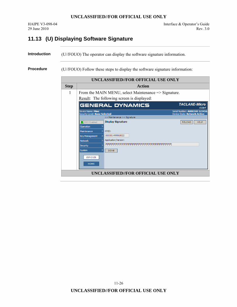
UNCLASSIFIED//FOR OFFICIAL USE ONLY HAIPE V3-098-04 Interface & Operator’s Guide 29 June 2010 Rev. 3.0
11-26
UNCLASSIFIED//FOR OFFICIAL USE ONLY
11.13 (U) Displaying Software Signature
Introduction (U//FOUO) The operator can display the software signature information.
Procedure (U//FOUO) Follow these steps to display the software signature information:
UNCLASSIFIED//FOR OFFICIAL USE ONLY Step Action
1 From the MAIN MENU, select Maintenance => Signature. Result: The following screen is displayed:
UNCLASSIFIED//FOR OFFICIAL USE ONLY
UNCLASSIFIED//FOR OFFICIAL USE ONLY Interface & Operator’s Guide HAIPE V3-098-04 Rev. 3.0 29 June 2010
11-27
UNCLASSIFIED//FOR OFFICIAL USE ONLY
11.14 (U) Zeroizing the TACLANE
Introduction (U//FOUO) The TACLANE supports three types of zeroization: 1) Panic zeroize
which deletes all keys in the TACLANE, 2) Selective zeroize which deletes a particular key (for details, see “Deleting Issued Keys”, “Deleting the FIREFLY Vector Set”, “Deleting a Pre-Placed Key Not Assigned to a Chain” and “Deleting a Pre-Placed Key Assigned to a Chain” of this document), and 3) Tamper zeroize which is the result of a tamper condition of the unit and all keys are deleted. (U//FOUO) This section describes how the operator can invoke a panic zeroize. An operator can initiate a panic zeroize from either: • (U//FOUO) The front panel ZEROIZE Button (TACLANE-Micro) or ZEROIZE
Buttons (TACLANE-GigE) or • (U//FOUO) The HMI Zeroize command.
Notes (U//FOUO) The following notes apply to panic zeroizing the TACLANE:
• (U//FOUO) A panic zeroize deletes all keys. • (U//FOUO) On startup after a panic zeroize, TACLANE displays a “TACLANE
zeroized” screen to alert the operator that a panic zeroize occurred. After the operator presses OK to continue, the message does not appear again until the next panic zeroize occurs.
• (U//FOUO) TACLANE may be filled with keys again immediately after recovery from a panic zeroize.
• (U//FOUO) The TACLANE-Micro will zeroize after detecting the pressing of the zeroize switch, from the front panel, three (3) times within a span of 10 seconds. The Micro will zeroize if the operator takes longer that 10 seconds, up to almost 25 seconds. This is the threshold designed to prevent accidental zeroize.
• (U//FOUO) When power is not applied to the TACLANE-Micro, the TACLANE-Micro will zeroize after detecting the pressing of the zeroize switch, from the front panel, two (2) times within a span of 10 seconds.
• (U//FOUO) The TACLANE-GigE will zeroize after detecting the simultaneous depression of both front-panel ZEROIZE buttons. Both buttons must be held down for at least 5 seconds. This technique is effective whether the GigE is powered or not.
Continued on next page
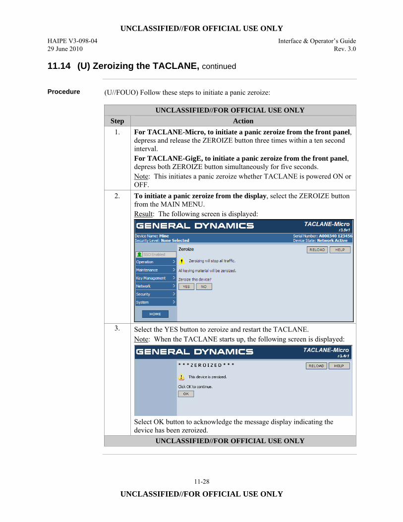
UNCLASSIFIED//FOR OFFICIAL USE ONLY HAIPE V3-098-04 Interface & Operator’s Guide 29 June 2010 Rev. 3.0
11-28
UNCLASSIFIED//FOR OFFICIAL USE ONLY
11.14 (U) Zeroizing the TACLANE, continued
Procedure (U//FOUO) Follow these steps to initiate a panic zeroize:
UNCLASSIFIED//FOR OFFICIAL USE ONLY Step Action
1. For TACLANE-Micro, to initiate a panic zeroize from the front panel, depress and release the ZEROIZE button three times within a ten second interval. For TACLANE-GigE, to initiate a panic zeroize from the front panel, depress both ZEROIZE button simultaneously for five seconds. Note: This initiates a panic zeroize whether TACLANE is powered ON or OFF.
2. To initiate a panic zeroize from the display, select the ZEROIZE button from the MAIN MENU. Result: The following screen is displayed:
3. Select the YES button to zeroize and restart the TACLANE. Note: When the TACLANE starts up, the following screen is displayed:
Select OK button to acknowledge the message display indicating the device has been zeroized.
UNCLASSIFIED//FOR OFFICIAL USE ONLY
UNCLASSIFIED//FOR OFFICIAL USE ONLY Interface & Operator’s Guide HAIPE V3-098-04 Rev. 3.0 29 June 2010
11-29
UNCLASSIFIED//FOR OFFICIAL USE ONLY
11.15 (U) Configuring/Displaying System Information
Introduction (U//FOUO) The operator can display the following TACLANE system information
which identifies the particular TACLANE unit: • (U//FOUO) TACLANE System Description – the up to 255-character, system
name. • (U//FOUO) TACLANE System Name – the up to 255-character, user-
configurable system name. • (U//FOUO) TACLANE System Contact – the up to 255-character, user-
configurable system contact information. • (U//FOUO) TACLANE System Location – the up to 255-character, user-
configurable system location. (U//FOUO) The operator can modify the following TACLANE system information: • TACLANE System Name • TACLANE System Contact • TACLANE System Location
Continued on next page
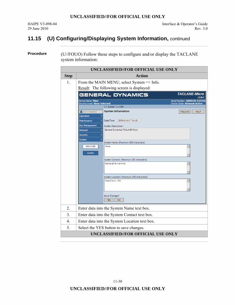
UNCLASSIFIED//FOR OFFICIAL USE ONLY HAIPE V3-098-04 Interface & Operator’s Guide 29 June 2010 Rev. 3.0
11-30
UNCLASSIFIED//FOR OFFICIAL USE ONLY
11.15 (U) Configuring/Displaying System Information, continued
Procedure (U//FOUO) Follow these steps to configure and/or display the TACLANE
system information:
UNCLASSIFIED//FOR OFFICIAL USE ONLY Step Action
1. From the MAIN MENU, select System => Info. Result: The following screen is displayed:
2. Enter data into the System Name text box. 3. Enter data into the System Contact text box. 4. Enter data into the System Location text box. 5. Select the YES button to save changes.
UNCLASSIFIED//FOR OFFICIAL USE ONLY
UNCLASSIFIED//FOR OFFICIAL USE ONLY Interface & Operator’s Guide HAIPE V3-098-04 Rev. 3.0 29 June 2010
11-31
UNCLASSIFIED//FOR OFFICIAL USE ONLY
11.16 (U) Enabling SSO Privileges
Introduction (U//FOUO) This command allows the TACLANE SSO operator to gain access to the
SSO-privileged HMI commands by entering the valid 9-digit SSO PIN.
Factory Default SSO PIN
(U//FOUO) The TACLANE delivered from the factory has the following default SSO PIN: 123456789. (U//FOUO) If a TACLANE is tampered, the SSO PIN will be reset to its default PIN (123456789) during tamper recovery.
Enable SSO Privileges Denied
(U//FOUO) If the operator fails to enter a valid SSO PIN in 5 consecutive attempts, the TACLANE must be manually restarted before another attempt can be made to enable SSO privileges. After the TACLANE restarts, the operator is able to access all the non-privileged HMI functions. If the operator wishes to gain access to the Enable SSO Privileges command again, the operator must select the Enable SSO Privileges command.
SSO Privileges Expiration
(U//FOUO) After 15 minutes of no SSO operator activity, the SSO access to the privileged commands expires. To regain access, the SSO operator must enter the valid SSO PIN in the Enable SSO Privileges screen. (U//FOUO) If the TACLANE is ever restarted, the operator must re-enter the SSO PIN to enable access to the SSO privileged commands.
Forgotten PIN (U//FOUO) If the operator has forgotten the current SSO PIN, SSO privileges can be
recovered using one of two methods. The first method is if a Network Manager is defined, the Network Manager using an SNMP command can reset the SSO PIN to the factory default SSO PIN (MIB object neResetSsoPin). The second method would be used if there is no Network Manager defined. In this situation, the only way to regain SSO privileges of the TACLANE is to perform the Field Tamper Recovery (see Section 10.3) on the TACLANE, which resets the PIN to the factory default SSO PIN (“123456789”).
Continued on next page
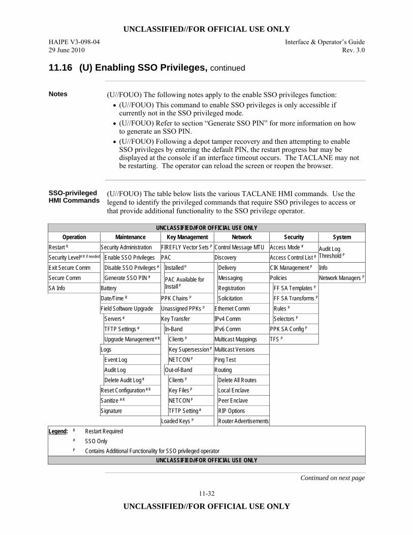
UNCLASSIFIED//FOR OFFICIAL USE ONLY HAIPE V3-098-04 Interface & Operator’s Guide 29 June 2010 Rev. 3.0
11-32
UNCLASSIFIED//FOR OFFICIAL USE ONLY
11.16 (U) Enabling SSO Privileges, continued
Notes (U//FOUO) The following notes apply to the enable SSO privileges function:
• (U//FOUO) This command to enable SSO privileges is only accessible if currently not in the SSO privileged mode.
• (U//FOUO) Refer to section “Generate SSO PIN” for more information on how to generate an SSO PIN.
• (U//FOUO) Following a depot tamper recovery and then attempting to enable SSO privileges by entering the default PIN, the restart progress bar may be displayed at the console if an interface timeout occurs. The TACLANE may not be restarting. The operator can reload the screen or reopen the browser.
SSO-privileged HMI Commands
(U//FOUO) The table below lists the various TACLANE HMI commands. Use the legend to identify the privileged commands that require SSO privileges to access or that provide additional functionality to the SSO privilege operator.
UNCLASSIFIED//FOR OFFICIAL USE ONLY
Operation Maintenance Key Management Network Security System Restart R Security Administration FIREFLY Vector Sets P Control Message MTU Access Mode # Audit Log
Threshold P Security Level# R if needed
Enable SSO Privileges PAC Discovery Access Control List # Exit Secure Comm Disable SSO Privileges #
Installed P
Delivery CIK Management P Info Secure Comm Generate SSO PIN # PAC Available for
Install P Messaging Policies Network Managers P
SA Info Battery Registration
FF SA Templates P
Date/Time R PPK Chains P Solicitation FF SA Transforms P Field Software Upgrade Unassigned PPKs P Ethernet Comm Rules P
Servers # Key Transfer IPv4 Comm Selectors P TFTP Settings #
In-Band IPv6 Comm PPK SA Config P Upgrade Management # R
Clients P Multicast Mappings TFS P
Logs Key Supersession P Multicast Versions
Event Log NETCON P Ping Test Audit Log Out-of-Band Routing Delete Audit Log # Clients P
Delete All Routes Reset Configuration # R
Key Files P Local Enclave
Sanitize # R NETCON P Peer Enclave Signature TFTP Setting # RIP Options Loaded Keys P Router Advertisements
Legend: R Restart Required # SSO Only P Contains Additional Functionality for SSO privileged operator
UNCLASSIFIED//FOR OFFICIAL USE ONLY
Continued on next page
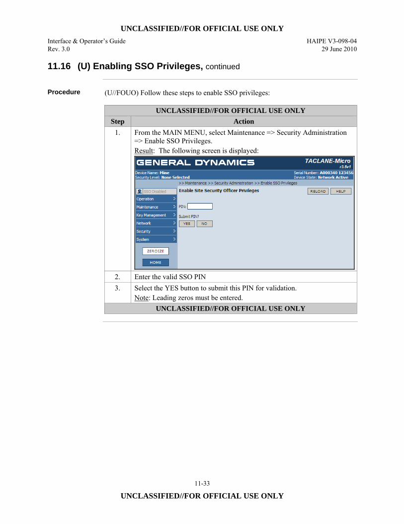
UNCLASSIFIED//FOR OFFICIAL USE ONLY Interface & Operator’s Guide HAIPE V3-098-04 Rev. 3.0 29 June 2010
11-33
UNCLASSIFIED//FOR OFFICIAL USE ONLY
11.16 (U) Enabling SSO Privileges, continued
Procedure (U//FOUO) Follow these steps to enable SSO privileges:
UNCLASSIFIED//FOR OFFICIAL USE ONLY Step Action
1. From the MAIN MENU, select Maintenance => Security Administration => Enable SSO Privileges. Result: The following screen is displayed:
2. Enter the valid SSO PIN 3. Select the YES button to submit this PIN for validation.
Note: Leading zeros must be entered. UNCLASSIFIED//FOR OFFICIAL USE ONLY
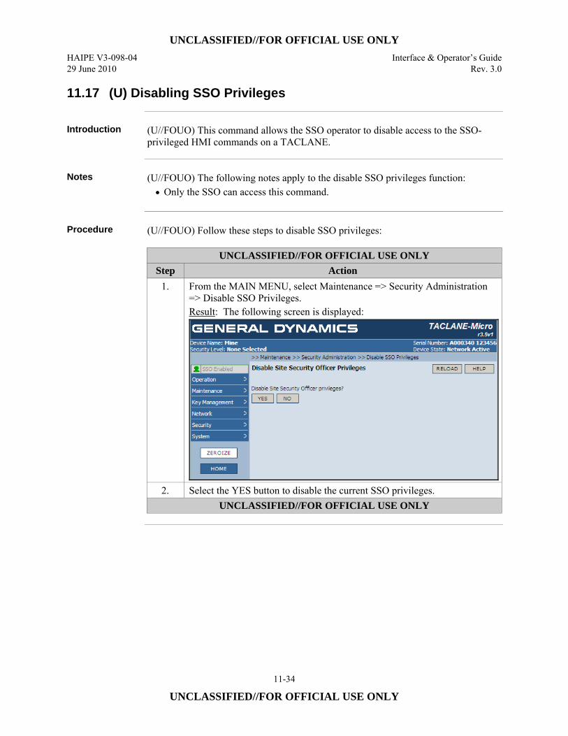
UNCLASSIFIED//FOR OFFICIAL USE ONLY HAIPE V3-098-04 Interface & Operator’s Guide 29 June 2010 Rev. 3.0
11-34
UNCLASSIFIED//FOR OFFICIAL USE ONLY
11.17 (U) Disabling SSO Privileges
Introduction (U//FOUO) This command allows the SSO operator to disable access to the SSO-
privileged HMI commands on a TACLANE.
Notes (U//FOUO) The following notes apply to the disable SSO privileges function:
• Only the SSO can access this command.
Procedure (U//FOUO) Follow these steps to disable SSO privileges:
UNCLASSIFIED//FOR OFFICIAL USE ONLY Step Action
1. From the MAIN MENU, select Maintenance => Security Administration => Disable SSO Privileges. Result: The following screen is displayed:
2. Select the YES button to disable the current SSO privileges. UNCLASSIFIED//FOR OFFICIAL USE ONLY
UNCLASSIFIED//FOR OFFICIAL USE ONLY Interface & Operator’s Guide HAIPE V3-098-04 Rev. 3.0 29 June 2010
11-35
UNCLASSIFIED//FOR OFFICIAL USE ONLY
11.18 (U) Generating SSO PIN
Introduction (U//FOUO) This command allows the SSO operator to have the TACLANE
generate/update the SSO PIN. The SSO PIN is a 9-digit, machine-generated PIN. When generating a PIN, the PIN is displayed and it must be acknowledged by the operator before it overwrites the previous SSO PIN. (U//FOUO) It is critical that the operator remembers to document the SSO PIN. Losing the SSO PIN will require that a remote Network Manager reset the PIN to the factory default or that the TACLANE unit undergo a Field Tamper Recovery in order to access the privileged commands.
Factory Default SSO PIN
(U//FOUO) The TACLANE delivered from the factory has the following default SSO PIN: 123456789. (U//FOUO) If a TACLANE is ever tampered, the SSO PIN will be reset to its default PIN (“123456789”) during tamper recovery.
Notes (U//FOUO) The following notes apply to the generate SSO PIN function:
• (U//FOUO) Only the SSO can access this command. • (U//FOUO) The TACLANE supports one SSO PIN. After the SSO PIN is
updated, the previous SSO PIN is no longer valid. • (U//FOUO) The operator must accept the PIN within five minutes of being
prompted, otherwise the PIN generation fails.
Continued on next page
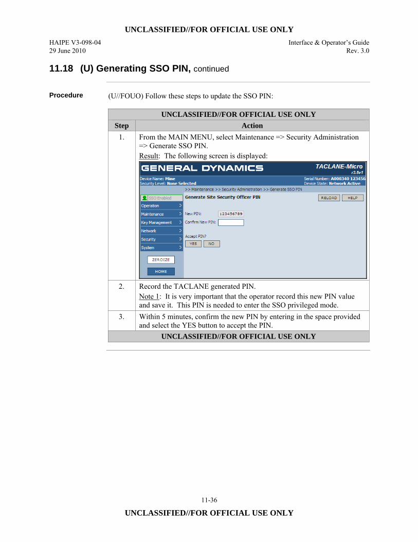
UNCLASSIFIED//FOR OFFICIAL USE ONLY HAIPE V3-098-04 Interface & Operator’s Guide 29 June 2010 Rev. 3.0
11-36
UNCLASSIFIED//FOR OFFICIAL USE ONLY
11.18 (U) Generating SSO PIN, continued
Procedure (U//FOUO) Follow these steps to update the SSO PIN:
UNCLASSIFIED//FOR OFFICIAL USE ONLY Step Action
1. From the MAIN MENU, select Maintenance => Security Administration => Generate SSO PIN. Result: The following screen is displayed:
2. Record the TACLANE generated PIN. Note 1: It is very important that the operator record this new PIN value and save it. This PIN is needed to enter the SSO privileged mode.
3. Within 5 minutes, confirm the new PIN by entering in the space provided and select the YES button to accept the PIN.
UNCLASSIFIED//FOR OFFICIAL USE ONLY
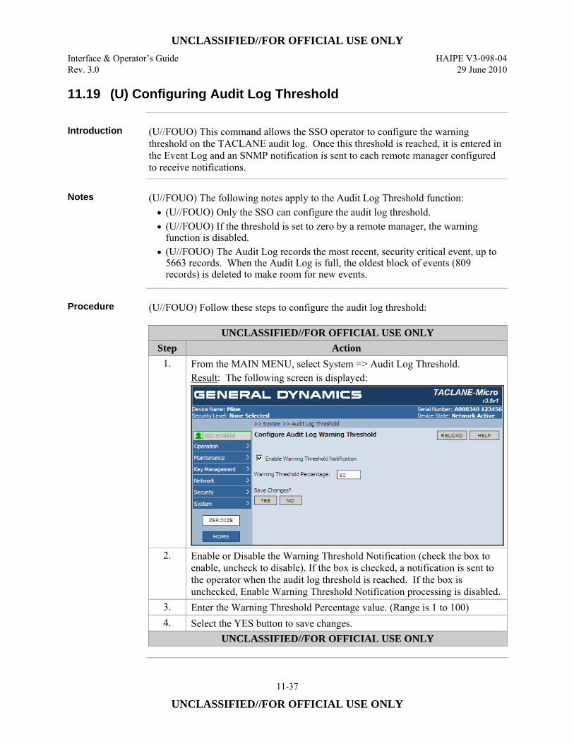
UNCLASSIFIED//FOR OFFICIAL USE ONLY Interface & Operator’s Guide HAIPE V3-098-04 Rev. 3.0 29 June 2010
11-37
UNCLASSIFIED//FOR OFFICIAL USE ONLY
11.19 (U) Configuring Audit Log Threshold
Introduction (U//FOUO) This command allows the SSO operator to configure the warning
threshold on the TACLANE audit log. Once this threshold is reached, it is entered in the Event Log and an SNMP notification is sent to each remote manager configured to receive notifications.
Notes (U//FOUO) The following notes apply to the Audit Log Threshold function:
• (U//FOUO) Only the SSO can configure the audit log threshold. • (U//FOUO) If the threshold is set to zero by a remote manager, the warning
function is disabled. • (U//FOUO) The Audit Log records the most recent, security critical event, up to
5663 records. When the Audit Log is full, the oldest block of events (809 records) is deleted to make room for new events.
Procedure (U//FOUO) Follow these steps to configure the audit log threshold:
UNCLASSIFIED//FOR OFFICIAL USE ONLY Step Action
1. From the MAIN MENU, select System => Audit Log Threshold. Result: The following screen is displayed:
2. Enable or Disable the Warning Threshold Notification (check the box to enable, uncheck to disable). If the box is checked, a notification is sent to the operator when the audit log threshold is reached. If the box is unchecked, Enable Warning Threshold Notification processing is disabled.
3. Enter the Warning Threshold Percentage value. (Range is 1 to 100) 4. Select the YES button to save changes.
UNCLASSIFIED//FOR OFFICIAL USE ONLY
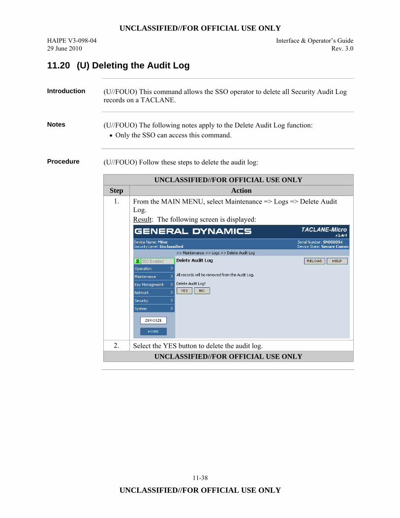
UNCLASSIFIED//FOR OFFICIAL USE ONLY HAIPE V3-098-04 Interface & Operator’s Guide 29 June 2010 Rev. 3.0
11-38
UNCLASSIFIED//FOR OFFICIAL USE ONLY
11.20 (U) Deleting the Audit Log
Introduction (U//FOUO) This command allows the SSO operator to delete all Security Audit Log
records on a TACLANE.
Notes (U//FOUO) The following notes apply to the Delete Audit Log function:
• Only the SSO can access this command.
Procedure (U//FOUO) Follow these steps to delete the audit log:
UNCLASSIFIED//FOR OFFICIAL USE ONLY Step Action
1. From the MAIN MENU, select Maintenance => Logs => Delete Audit Log. Result: The following screen is displayed:
2. Select the YES button to delete the audit log. UNCLASSIFIED//FOR OFFICIAL USE ONLY

UNCLASSIFIED//FOR OFFICIAL USE ONLY Interface & Operator’s Guide HAIPE V3-098-04 Rev. 3.0 29 June 2010
11-39
UNCLASSIFIED//FOR OFFICIAL USE ONLY
11.21 (U) Displaying the Audit Log
Introduction (U//FOUO) This command allows the operator to display the Security Audit Log
records on a TACLANE.
Notes (U//FOUO) The following notes apply to the Display Audit Log function:
• (U//FOUO) When the Audit Log reaches the maximum records (5663), the oldest block of the Audit Log is removed (809 records) to allow additional events to be logged.
• (U//FOUO) See Appendix C for a list of Audit Log events.
Procedure (U//FOUO) Follow these steps to display the audit log:
UNCLASSIFIED//FOR OFFICIAL USE ONLY Step Action
1. From the MAIN MENU, select Maintenance => Logs => Audit Log. Result: The following screen is displayed:
2. Select NEXT to display the next page of audit log records, PREV to display the previous page of audit log records, or select the page number to display a particular page of audit log records, if available.
UNCLASSIFIED//FOR OFFICIAL USE ONLY
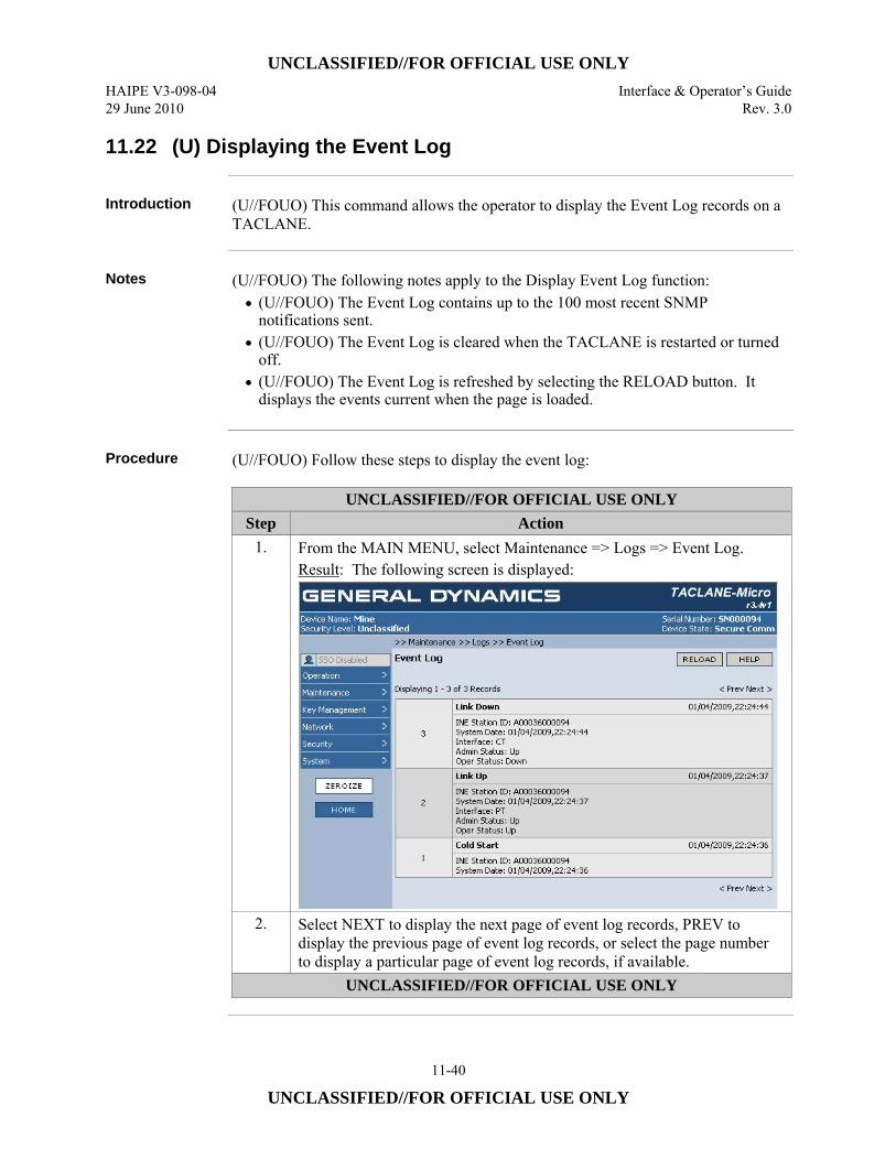
UNCLASSIFIED//FOR OFFICIAL USE ONLY HAIPE V3-098-04 Interface & Operator’s Guide 29 June 2010 Rev. 3.0
11-40
UNCLASSIFIED//FOR OFFICIAL USE ONLY
11.22 (U) Displaying the Event Log
Introduction (U//FOUO) This command allows the operator to display the Event Log records on a
TACLANE.
Notes (U//FOUO) The following notes apply to the Display Event Log function:
• (U//FOUO) The Event Log contains up to the 100 most recent SNMP notifications sent.
• (U//FOUO) The Event Log is cleared when the TACLANE is restarted or turned off.
• (U//FOUO) The Event Log is refreshed by selecting the RELOAD button. It displays the events current when the page is loaded.
Procedure (U//FOUO) Follow these steps to display the event log:
UNCLASSIFIED//FOR OFFICIAL USE ONLY Step Action
1. From the MAIN MENU, select Maintenance => Logs => Event Log. Result: The following screen is displayed:
2. Select NEXT to display the next page of event log records, PREV to display the previous page of event log records, or select the page number to display a particular page of event log records, if available.
UNCLASSIFIED//FOR OFFICIAL USE ONLY
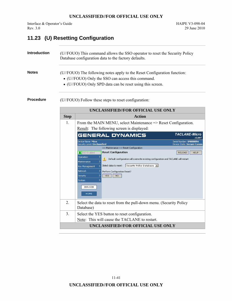
UNCLASSIFIED//FOR OFFICIAL USE ONLY Interface & Operator’s Guide HAIPE V3-098-04 Rev. 3.0 29 June 2010
11-41
UNCLASSIFIED//FOR OFFICIAL USE ONLY
11.23 (U) Resetting Configuration
Introduction (U//FOUO) This command allows the SSO operator to reset the Security Policy
Database configuration data to the factory defaults.
Notes (U//FOUO) The following notes apply to the Reset Configuration function:
• (U//FOUO) Only the SSO can access this command. • (U//FOUO) Only SPD data can be reset using this screen.
Procedure (U//FOUO) Follow these steps to reset configuration:
UNCLASSIFIED//FOR OFFICIAL USE ONLY Step Action
1. From the MAIN MENU, select Maintenance => Reset Configuration. Result: The following screen is displayed:
2. Select the data to reset from the pull-down menu. (Security Policy Database)
3. Select the YES button to reset configuration. Note: This will cause the TACLANE to restart.
UNCLASSIFIED//FOR OFFICIAL USE ONLY
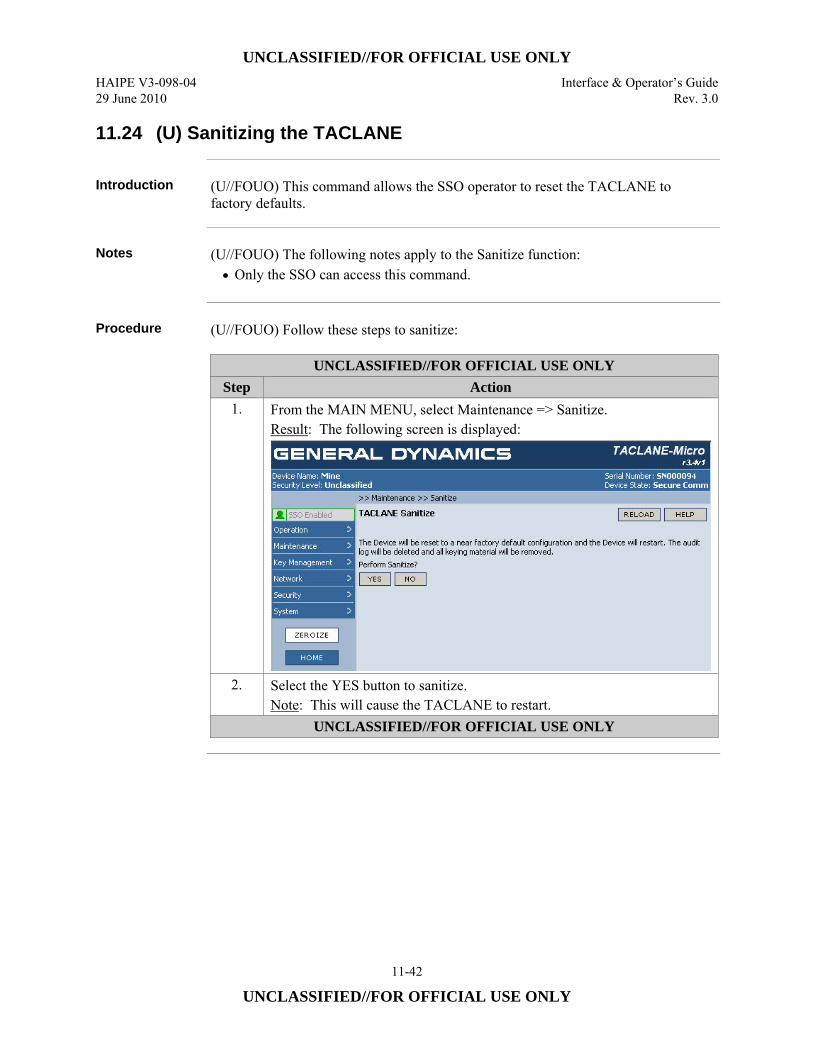
UNCLASSIFIED//FOR OFFICIAL USE ONLY HAIPE V3-098-04 Interface & Operator’s Guide 29 June 2010 Rev. 3.0
11-42
UNCLASSIFIED//FOR OFFICIAL USE ONLY
11.24 (U) Sanitizing the TACLANE
Introduction (U//FOUO) This command allows the SSO operator to reset the TACLANE to
factory defaults.
Notes (U//FOUO) The following notes apply to the Sanitize function:
• Only the SSO can access this command.
Procedure (U//FOUO) Follow these steps to sanitize:
UNCLASSIFIED//FOR OFFICIAL USE ONLY Step Action
1. From the MAIN MENU, select Maintenance => Sanitize. Result: The following screen is displayed:
2. Select the YES button to sanitize. Note: This will cause the TACLANE to restart.
UNCLASSIFIED//FOR OFFICIAL USE ONLY
UNCLASSIFIED//FOR OFFICIAL USE ONLY Interface & Operator’s Guide HAIPE V3-098-04 Rev. 3.0 29 June 2010
12-1
UNCLASSIFIED//FOR OFFICIAL USE ONLY
12.0 (U) TROUBLESHOOTING TACLANE
12.1 (U) Alarm
Introduction (U//FOUO) An alarm is the result of an internal failure. When a TACLANE is in an
alarm condition, the ALARM LED is illuminated. (U//FOUO) Note: The ALARM LED is illuminated briefly during diagnostics. This is normal.
Alarm Recovery
(U//FOUO) TACLANE automatically attempts to recover from an alarm. TACLANE automatically resets during alarm recovery and attempts to return to the previous operating mode. After two successive alarms of the same type, the TACLANE will halt (i.e., it will stop attempting to restart). Power can be cycled by the operator to attempt to recover from a repeated alarm condition. If the condition persists, the TACLANE must be returned to the depot for repair. Note the circumstances surrounding the alarm, as this information may be useful to depot personnel.
12.2 (U) Tamper
Introduction (U//FOUO) Tamper is the result of opening the TACLANE chassis, loss of battery
power when powered off, or removal of the battery while the TACLANE is powered off. When a TACLANE is in a tamper condition, the TAMPER status LED is illuminated. (U//FOUO) Note: All keys are automatically deleted when a tamper condition is detected. (U//FOUO) Depot Tamper Recovery is a factory level option and not discussed in this manual.
Tamper Recovery
(U//FOUO) A tampered unit can be recovered in the field. See Section 12.3 “Performing a Field Tamper Recovery,” for more information.
UNCLASSIFIED//FOR OFFICIAL USE ONLY HAIPE V3-098-04 Interface & Operator’s Guide 29 June 2010 Rev. 3.0
12-2
UNCLASSIFIED//FOR OFFICIAL USE ONLY
12.3 (U) Performing a Field Tamper Recovery
Introduction (U//FOUO) The operator can perform a Field Tamper Recovery (FTR) using a
Recovery CIK to recover a TACLANE that has become tampered. FTR can also be used 1) to create CIK1 if there are no valid CIKs, 2) to reset the SSO PIN (may also be reset from the Network Manager), and 3) may help recover a TACLANE from a continuous alarm state. In cases where the unit is not already tampered, first tamper the unit by removing the battery without power applied. Then follow the Field Tamper Recovery procedure below.
Important Note (U//FOUO) Before performing a Field Tamper Recovery, the TACLANE operator
must determine if the tamper was benign (e.g., depleted battery). The unit must be visually inspected, ensuring that the tamper seals are intact. (U//FOUO) Evidence of physical tampering must be reported to NSA in accordance with TACLANE doctrine.
New CIK (U//FOUO) Obtain a KSD before beginning this procedure. This KSD will become
CIK1 for this TACLANE. Do not use a CIK that is required for another TACLANE as that will make it invalid for the other TACLANE.
Field Tamper Recovery CIK
(U//FOUO) A Recovery CIK is unique to its associated TACLANE. The Recovery CIK should be tagged with the serial number of the associated TACLANE. It can be used to recover its associated TACLANE from tamper a maximum of five times. After it has been used five times, a Recovery CIK is no longer valid. The tag attached to the Recovery CIK should be used to identify its associated TACLANE and to keep a record of the number of times that Recovery CIK is used for tamper recovery. (U//FOUO) The Recovery CIK is classified SECRET, and must be handled according to NSA doctrine.
Battery Replacement
(U//FOUO) A benign tamper is typically due to a depleted battery. It is recommended that the battery be replaced during a Field Tamper Recovery.
Continued on next page
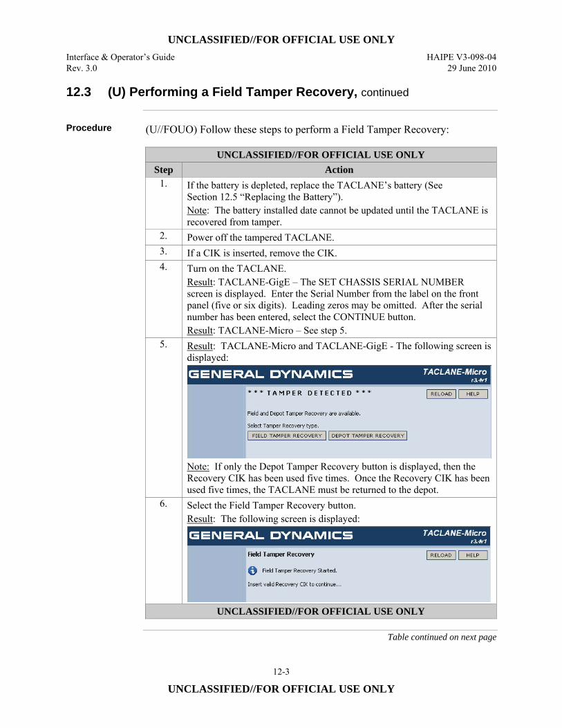
UNCLASSIFIED//FOR OFFICIAL USE ONLY Interface & Operator’s Guide HAIPE V3-098-04 Rev. 3.0 29 June 2010
12-3
UNCLASSIFIED//FOR OFFICIAL USE ONLY
12.3 (U) Performing a Field Tamper Recovery, continued
Procedure (U//FOUO) Follow these steps to perform a Field Tamper Recovery:
UNCLASSIFIED//FOR OFFICIAL USE ONLY Step Action
1. If the battery is depleted, replace the TACLANE’s battery (See Section 12.5 “Replacing the Battery”). Note: The battery installed date cannot be updated until the TACLANE is recovered from tamper.
2. Power off the tampered TACLANE. 3. If a CIK is inserted, remove the CIK. 4. Turn on the TACLANE.
Result: TACLANE-GigE – The SET CHASSIS SERIAL NUMBER screen is displayed. Enter the Serial Number from the label on the front panel (five or six digits). Leading zeros may be omitted. After the serial number has been entered, select the CONTINUE button. Result: TACLANE-Micro – See step 5.
5. Result: TACLANE-Micro and TACLANE-GigE - The following screen is displayed:
Note: If only the Depot Tamper Recovery button is displayed, then the Recovery CIK has been used five times. Once the Recovery CIK has been used five times, the TACLANE must be returned to the depot.
6. Select the Field Tamper Recovery button. Result: The following screen is displayed:
UNCLASSIFIED//FOR OFFICIAL USE ONLY
Table continued on next page
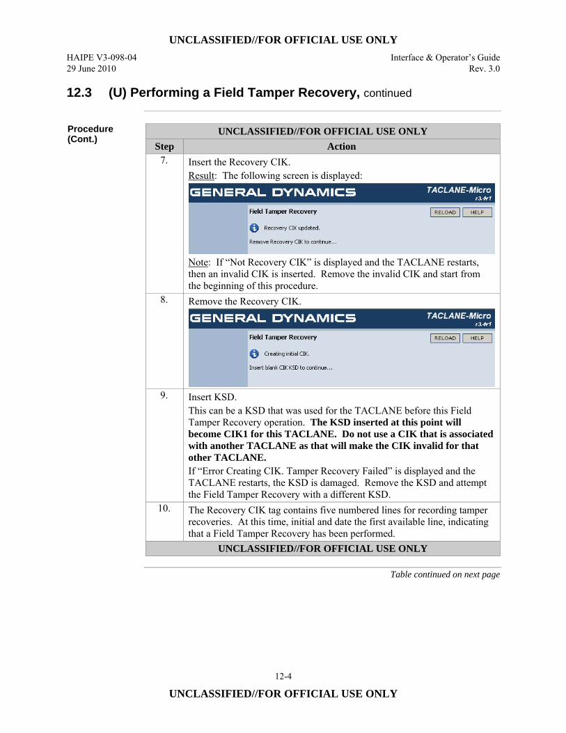
UNCLASSIFIED//FOR OFFICIAL USE ONLY HAIPE V3-098-04 Interface & Operator’s Guide 29 June 2010 Rev. 3.0
12-4
UNCLASSIFIED//FOR OFFICIAL USE ONLY
12.3 (U) Performing a Field Tamper Recovery, continued
Procedure (Cont.)
UNCLASSIFIED//FOR OFFICIAL USE ONLY Step Action
7. Insert the Recovery CIK. Result: The following screen is displayed:
Note: If “Not Recovery CIK” is displayed and the TACLANE restarts, then an invalid CIK is inserted. Remove the invalid CIK and start from the beginning of this procedure.
8. Remove the Recovery CIK.
9. Insert KSD. This can be a KSD that was used for the TACLANE before this Field Tamper Recovery operation. The KSD inserted at this point will become CIK1 for this TACLANE. Do not use a CIK that is associated with another TACLANE as that will make the CIK invalid for that other TACLANE. If “Error Creating CIK. Tamper Recovery Failed” is displayed and the TACLANE restarts, the KSD is damaged. Remove the KSD and attempt the Field Tamper Recovery with a different KSD.
10. The Recovery CIK tag contains five numbered lines for recording tamper recoveries. At this time, initial and date the first available line, indicating that a Field Tamper Recovery has been performed.
UNCLASSIFIED//FOR OFFICIAL USE ONLY
Table continued on next page
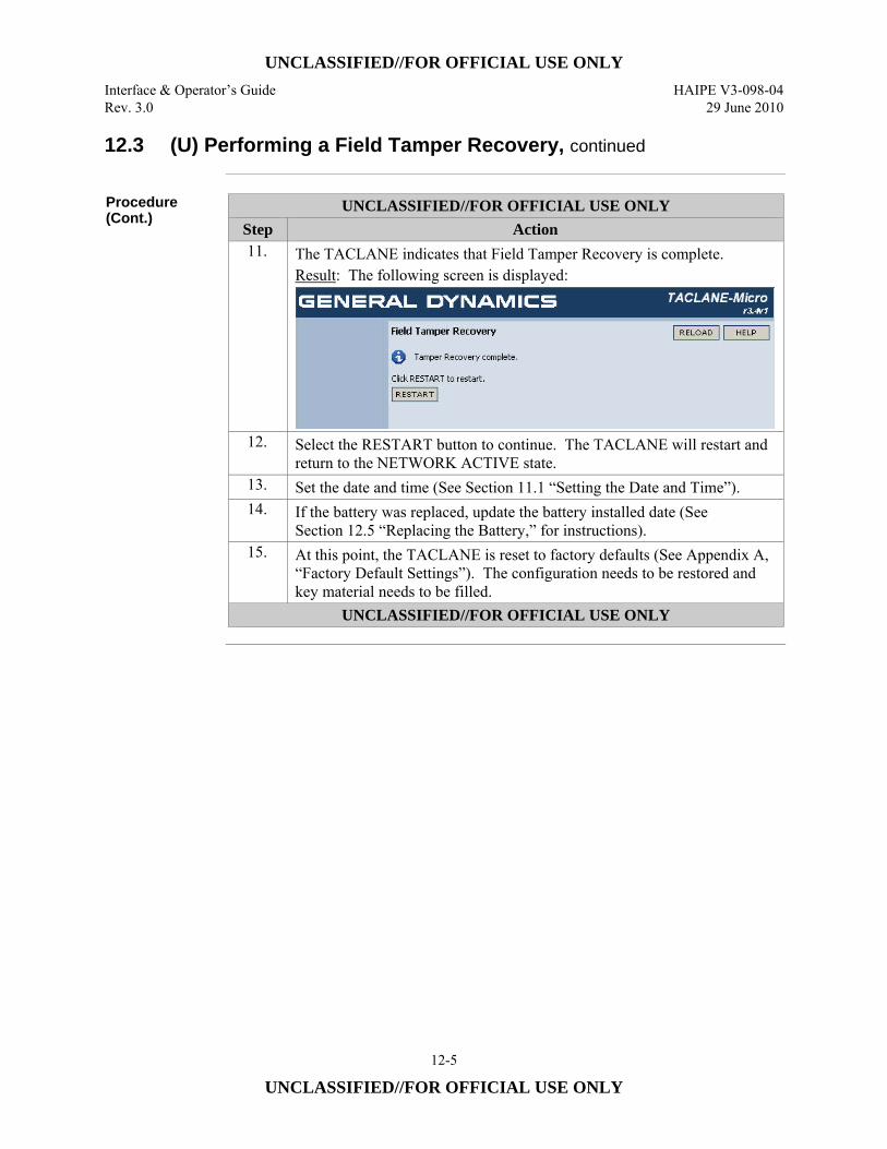
UNCLASSIFIED//FOR OFFICIAL USE ONLY Interface & Operator’s Guide HAIPE V3-098-04 Rev. 3.0 29 June 2010
12-5
UNCLASSIFIED//FOR OFFICIAL USE ONLY
12.3 (U) Performing a Field Tamper Recovery, continued
Procedure (Cont.)
UNCLASSIFIED//FOR OFFICIAL USE ONLY Step Action 11. The TACLANE indicates that Field Tamper Recovery is complete.
Result: The following screen is displayed:
12. Select the RESTART button to continue. The TACLANE will restart and return to the NETWORK ACTIVE state.
13. Set the date and time (See Section 11.1 “Setting the Date and Time”). 14. If the battery was replaced, update the battery installed date (See
Section 12.5 “Replacing the Battery,” for instructions). 15. At this point, the TACLANE is reset to factory defaults (See Appendix A,
“Factory Default Settings”). The configuration needs to be restored and key material needs to be filled.
UNCLASSIFIED//FOR OFFICIAL USE ONLY
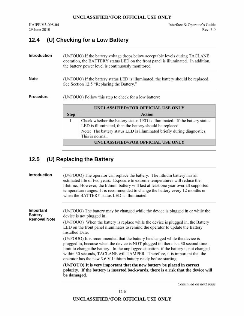
UNCLASSIFIED//FOR OFFICIAL USE ONLY HAIPE V3-098-04 Interface & Operator’s Guide 29 June 2010 Rev. 3.0
12-6
UNCLASSIFIED//FOR OFFICIAL USE ONLY
12.4 (U) Checking for a Low Battery
Introduction (U//FOUO) If the battery voltage drops below acceptable levels during TACLANE
operation, the BATTERY status LED on the front panel is illuminated. In addition, the battery power level is continuously monitored.
Note (U//FOUO) If the battery status LED is illuminated, the battery should be replaced.
See Section 12.5 “Replacing the Battery.”
Procedure (U//FOUO) Follow this step to check for a low battery:
UNCLASSIFIED//FOR OFFICIAL USE ONLY Step Action
1. Check whether the battery status LED is illuminated. If the battery status LED is illuminated, then the battery should be replaced. Note: The battery status LED is illuminated briefly during diagnostics. This is normal.
UNCLASSIFIED//FOR OFFICIAL USE ONLY
12.5 (U) Replacing the Battery
Introduction (U//FOUO) The operator can replace the battery. The lithium battery has an
estimated life of two years. Exposure to extreme temperatures will reduce the lifetime. However, the lithium battery will last at least one year over all supported temperature ranges. It is recommended to change the battery every 12 months or when the BATTERY status LED is illuminated.
Important Battery Removal Note
(U//FOUO) The battery may be changed while the device is plugged in or while the device is not plugged in. (U//FOUO) When the battery is replace while the device is plugged in, the Battery LED on the front panel illuminates to remind the operator to update the Battery Installed Date. (U//FOUO) It is recommended that the battery be changed while the device is plugged in, because when the device is NOT plugged in, there is a 30 second time limit to change the battery. In the unplugged situation, if the battery is not changed within 30 seconds, TACLANE will TAMPER. Therefore, it is important that the operator has the new 3.6 V Lithium battery ready before starting. (U//FOUO) It is very important that the new battery be placed in correct polarity. If the battery is inserted backwards, there is a risk that the device will be damaged.
Continued on next page
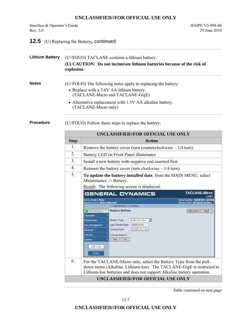
UNCLASSIFIED//FOR OFFICIAL USE ONLY Interface & Operator’s Guide HAIPE V3-098-04 Rev. 3.0 29 June 2010
12-7
UNCLASSIFIED//FOR OFFICIAL USE ONLY
12.5 (U) Replacing the Battery, continued
Lithium Battery (U//FOUO) TACLANE contains a lithium battery.
(U) CAUTION: Do not incinerate lithium batteries because of the risk of explosion.
Notes (U//FOUO) The following notes apply to replacing the battery:
• Replace with a 3.6V AA lithium battery. (TACLANE-Micro and TACLANE-GigE)
• Alternative replacement with 1.5V AA alkaline battery. (TACLANE-Micro only)
Procedure (U//FOUO) Follow these steps to replace the battery:
UNCLASSIFIED//FOR OFFICIAL USE ONLY Step Action
1. Remove the battery cover (turn counterclockwise – 1/4 turn). 2. Battery LED on Front Panel illuminates 3. Install a new battery with negative end inserted first. 4. Reinsert the battery cover (turn clockwise – 1/4 turn). 5. To update the battery installed date, from the MAIN MENU, select
Maintenance -> Battery. Result: The following screen is displayed:
6. For the TACLANE-Micro only, select the Battery Type from the pull-down menu (Alkaline, Lithium-Ion). The TACLANE-GigE is restricted to Lithium-Ion batteries and does not support Alkaline battery operation.
UNCLASSIFIED//FOR OFFICIAL USE ONLY
Table continued on next page
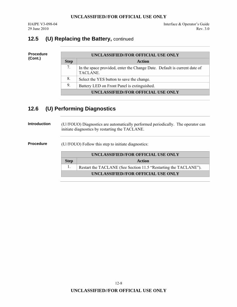
UNCLASSIFIED//FOR OFFICIAL USE ONLY HAIPE V3-098-04 Interface & Operator’s Guide 29 June 2010 Rev. 3.0
12-8
UNCLASSIFIED//FOR OFFICIAL USE ONLY
12.5 (U) Replacing the Battery, continued
Procedure (Cont.)
UNCLASSIFIED//FOR OFFICIAL USE ONLY Step Action
7. In the space provided, enter the Change Date. Default is current date of TACLANE.
8. Select the YES button to save the change. 9. Battery LED on Front Panel is extinguished.
UNCLASSIFIED//FOR OFFICIAL USE ONLY
12.6 (U) Performing Diagnostics
Introduction (U//FOUO) Diagnostics are automatically performed periodically. The operator can
initiate diagnostics by restarting the TACLANE.
Procedure (U//FOUO) Follow this step to initiate diagnostics:
UNCLASSIFIED//FOR OFFICIAL USE ONLY Step Action
1. Restart the TACLANE (See Section 11.5 “Restarting the TACLANE”). UNCLASSIFIED//FOR OFFICIAL USE ONLY
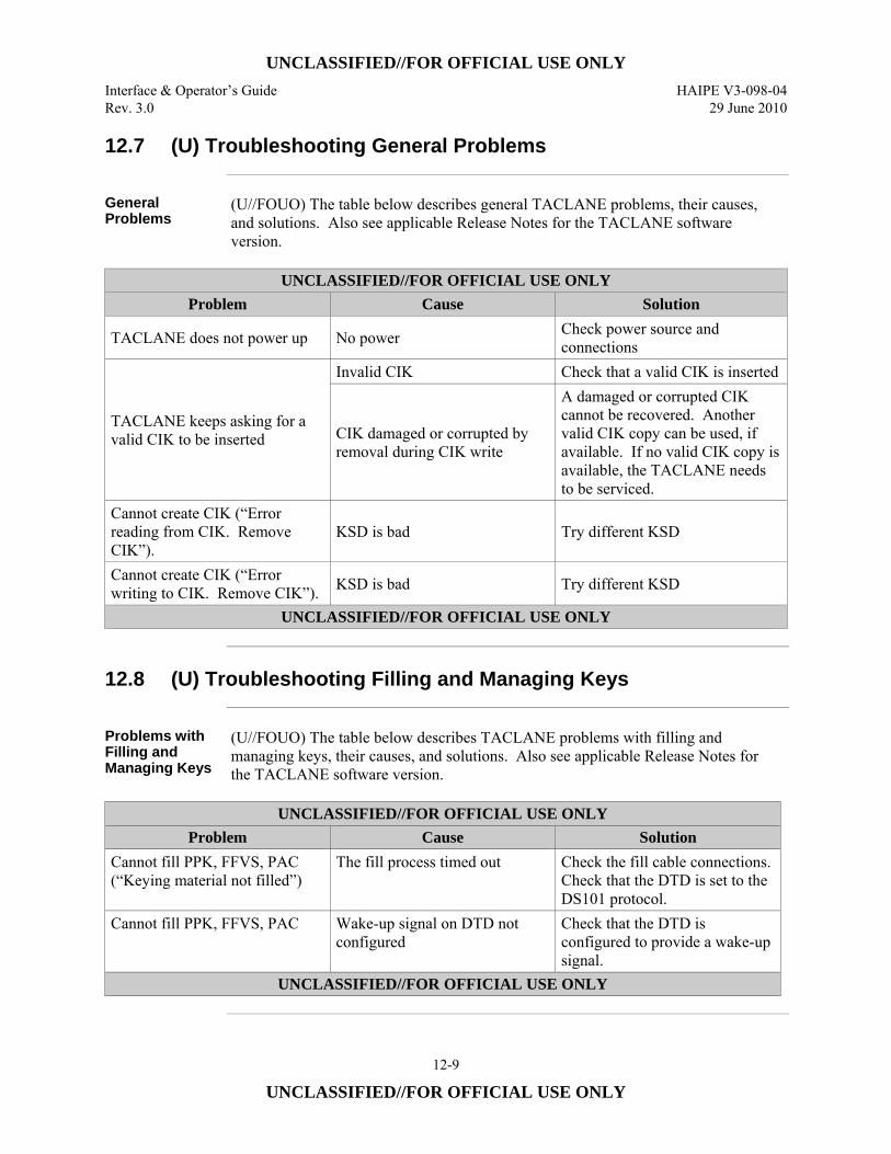
UNCLASSIFIED//FOR OFFICIAL USE ONLY Interface & Operator’s Guide HAIPE V3-098-04 Rev. 3.0 29 June 2010
12-9
UNCLASSIFIED//FOR OFFICIAL USE ONLY
12.7 (U) Troubleshooting General Problems
General Problems
(U//FOUO) The table below describes general TACLANE problems, their causes, and solutions. Also see applicable Release Notes for the TACLANE software version.
UNCLASSIFIED//FOR OFFICIAL USE ONLY
Problem Cause Solution
TACLANE does not power up No power Check power source and connections
TACLANE keeps asking for a valid CIK to be inserted
Invalid CIK Check that a valid CIK is inserted
CIK damaged or corrupted by removal during CIK write
A damaged or corrupted CIK cannot be recovered. Another valid CIK copy can be used, if available. If no valid CIK copy is available, the TACLANE needs to be serviced.
Cannot create CIK (“Error reading from CIK. Remove CIK”).
KSD is bad Try different KSD
Cannot create CIK (“Error writing to CIK. Remove CIK”). KSD is bad Try different KSD
UNCLASSIFIED//FOR OFFICIAL USE ONLY
12.8 (U) Troubleshooting Filling and Managing Keys
Problems with Filling and Managing Keys
(U//FOUO) The table below describes TACLANE problems with filling and managing keys, their causes, and solutions. Also see applicable Release Notes for the TACLANE software version.
UNCLASSIFIED//FOR OFFICIAL USE ONLY
Problem Cause Solution Cannot fill PPK, FFVS, PAC (“Keying material not filled”)
The fill process timed out Check the fill cable connections. Check that the DTD is set to the DS101 protocol.
Cannot fill PPK, FFVS, PAC Wake-up signal on DTD not configured
Check that the DTD is configured to provide a wake-up signal.
UNCLASSIFIED//FOR OFFICIAL USE ONLY
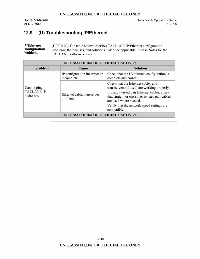
UNCLASSIFIED//FOR OFFICIAL USE ONLY HAIPE V3-098-04 Interface & Operator’s Guide 29 June 2010 Rev. 3.0
12-10
UNCLASSIFIED//FOR OFFICIAL USE ONLY
12.9 (U) Troubleshooting IP/Ethernet
IP/Ethernet Configuration Problems
(U//FOUO) The table below describes TACLANE IP/Ethernet configuration problems, their causes, and solutions. Also see applicable Release Notes for the TACLANE software version.
UNCLASSIFIED//FOR OFFICIAL USE ONLY
Problem Cause Solution
Cannot ping TACLANE IP addresses
IP configuration incorrect or incomplete
Check that the IP/Ethernet configuration is complete and correct.
Ethernet cable/transceiver problem
Check that the Ethernet cables and transceivers (if used) are working properly. If using twisted pair Ethernet cables, check that straight or crossover twisted pair cables are used where needed. Verify that the network speed settings are compatible.
UNCLASSIFIED//FOR OFFICIAL USE ONLY
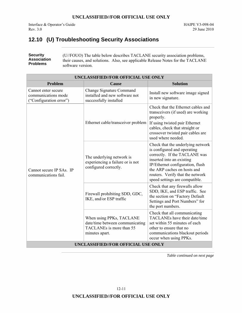
UNCLASSIFIED//FOR OFFICIAL USE ONLY Interface & Operator’s Guide HAIPE V3-098-04 Rev. 3.0 29 June 2010
12-11
UNCLASSIFIED//FOR OFFICIAL USE ONLY
12.10 (U) Troubleshooting Security Associations
Security Association Problems
(U//FOUO) The table below describes TACLANE security association problems, their causes, and solutions. Also, see applicable Release Notes for the TACLANE software version.
UNCLASSIFIED//FOR OFFICIAL USE ONLY
Problem Cause Solution Cannot enter secure communications mode (“Configuration error”)
Change Signature Command installed and new software not successfully installed
Install new software image signed in new signature.
Cannot secure IP SAs. IP communications fail.
Ethernet cable/transceiver problem
Check that the Ethernet cables and transceivers (if used) are working properly. If using twisted pair Ethernet cables, check that straight or crossover twisted pair cables are used where needed.
The underlying network is experiencing a failure or is not configured correctly.
Check that the underlying network is configured and operating correctly. If the TACLANE was inserted into an existing IP/Ethernet configuration, flush the ARP caches on hosts and routers. Verify that the network speed settings are compatible.
Firewall prohibiting SDD, GDC, IKE, and/or ESP traffic
Check that any firewalls allow SDD, IKE, and ESP traffic. See the section on “Factory Default Settings and Port Numbers” for the port numbers.
When using PPKs, TACLANE date/time between communicating TACLANEs is more than 55 minutes apart.
Check that all communicating TACLANEs have their date/time set within 55 minutes of each other to ensure that no communications blackout periods occur when using PPKs.
UNCLASSIFIED//FOR OFFICIAL USE ONLY
Table continued on next page
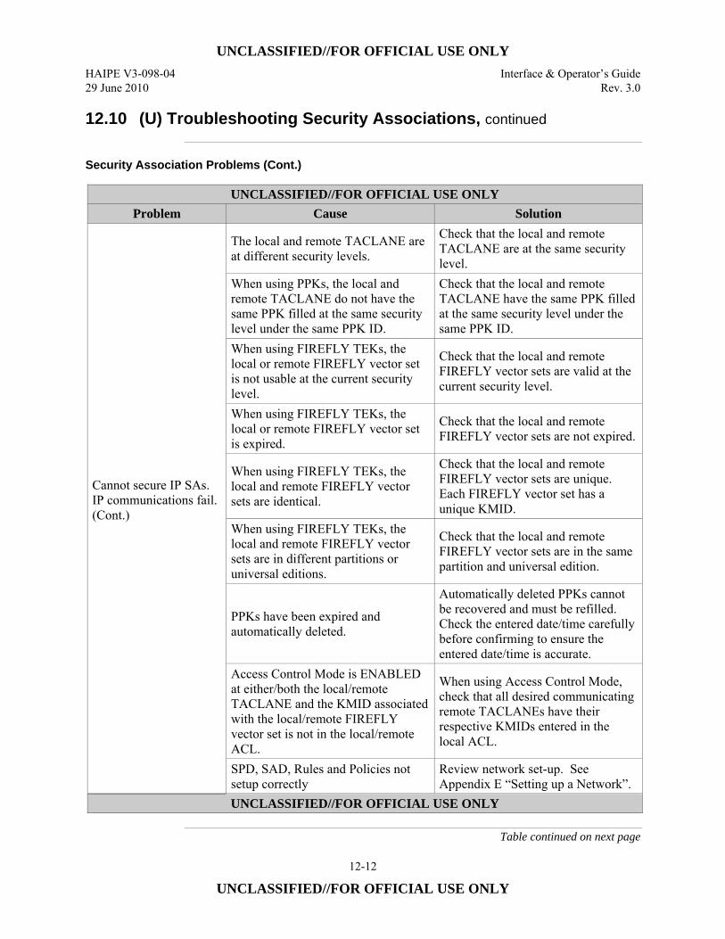
UNCLASSIFIED//FOR OFFICIAL USE ONLY HAIPE V3-098-04 Interface & Operator’s Guide 29 June 2010 Rev. 3.0
12-12
UNCLASSIFIED//FOR OFFICIAL USE ONLY
12.10 (U) Troubleshooting Security Associations, continued
Security Association Problems (Cont.)
UNCLASSIFIED//FOR OFFICIAL USE ONLY Problem Cause Solution
Cannot secure IP SAs. IP communications fail. (Cont.)
The local and remote TACLANE are at different security levels.
Check that the local and remote TACLANE are at the same security level.
When using PPKs, the local and remote TACLANE do not have the same PPK filled at the same security level under the same PPK ID.
Check that the local and remote TACLANE have the same PPK filled at the same security level under the same PPK ID.
When using FIREFLY TEKs, the local or remote FIREFLY vector set is not usable at the current security level.
Check that the local and remote FIREFLY vector sets are valid at the current security level.
When using FIREFLY TEKs, the local or remote FIREFLY vector set is expired.
Check that the local and remote FIREFLY vector sets are not expired.
When using FIREFLY TEKs, the local and remote FIREFLY vector sets are identical.
Check that the local and remote FIREFLY vector sets are unique. Each FIREFLY vector set has a unique KMID.
When using FIREFLY TEKs, the local and remote FIREFLY vector sets are in different partitions or universal editions.
Check that the local and remote FIREFLY vector sets are in the same partition and universal edition.
PPKs have been expired and automatically deleted.
Automatically deleted PPKs cannot be recovered and must be refilled. Check the entered date/time carefully before confirming to ensure the entered date/time is accurate.
Access Control Mode is ENABLED at either/both the local/remote TACLANE and the KMID associated with the local/remote FIREFLY vector set is not in the local/remote ACL.
When using Access Control Mode, check that all desired communicating remote TACLANEs have their respective KMIDs entered in the local ACL.
SPD, SAD, Rules and Policies not setup correctly
Review network set-up. See Appendix E “Setting up a Network”.
UNCLASSIFIED//FOR OFFICIAL USE ONLY
Table continued on next page
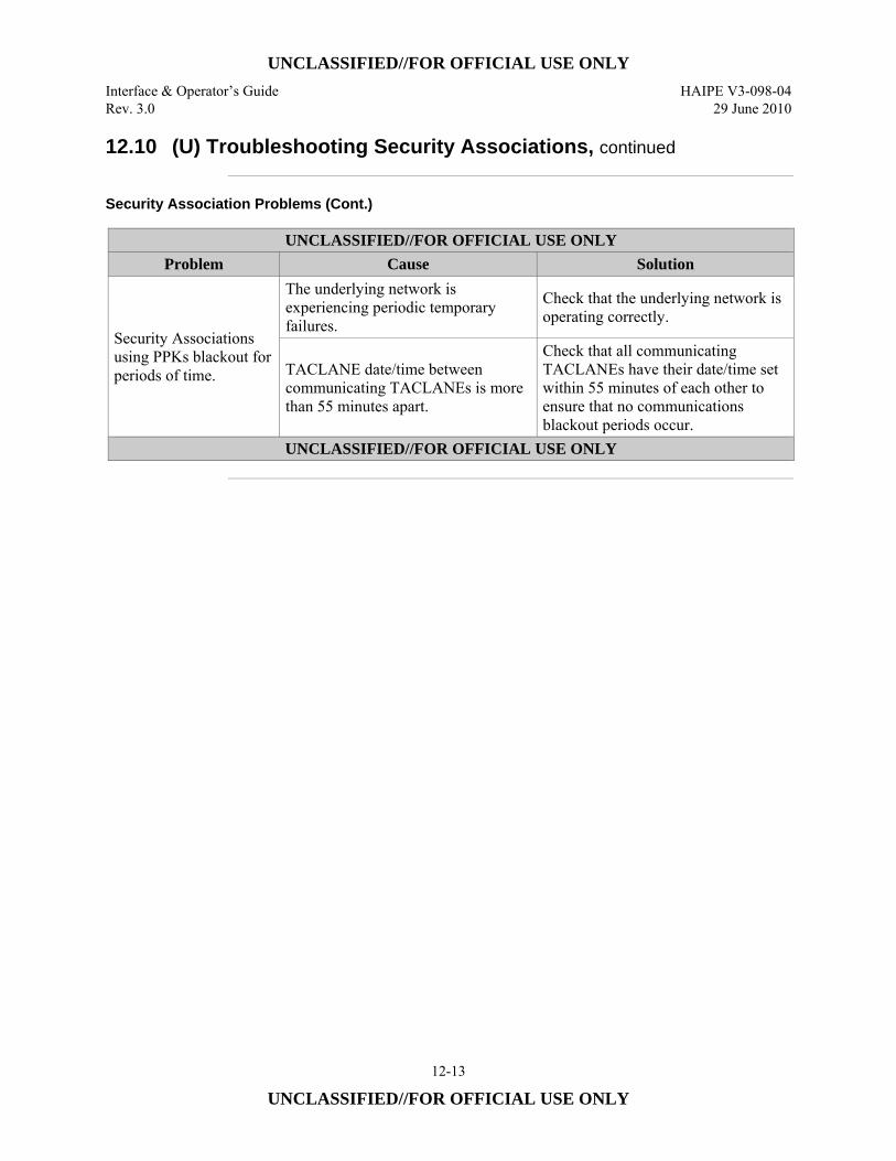
UNCLASSIFIED//FOR OFFICIAL USE ONLY Interface & Operator’s Guide HAIPE V3-098-04 Rev. 3.0 29 June 2010
12-13
UNCLASSIFIED//FOR OFFICIAL USE ONLY
12.10 (U) Troubleshooting Security Associations, continued
Security Association Problems (Cont.)
UNCLASSIFIED//FOR OFFICIAL USE ONLY Problem Cause Solution
Security Associations using PPKs blackout for periods of time.
The underlying network is experiencing periodic temporary failures.
Check that the underlying network is operating correctly.
TACLANE date/time between communicating TACLANEs is more than 55 minutes apart.
Check that all communicating TACLANEs have their date/time set within 55 minutes of each other to ensure that no communications blackout periods occur.
UNCLASSIFIED//FOR OFFICIAL USE ONLY

UNCLASSIFIED//FOR OFFICIAL USE ONLY HAIPE V3-098-04 Interface & Operator’s Guide 29 June 2010 Rev. 3.0
12-14
UNCLASSIFIED//FOR OFFICIAL USE ONLY
(U) This page intentionally left blank.
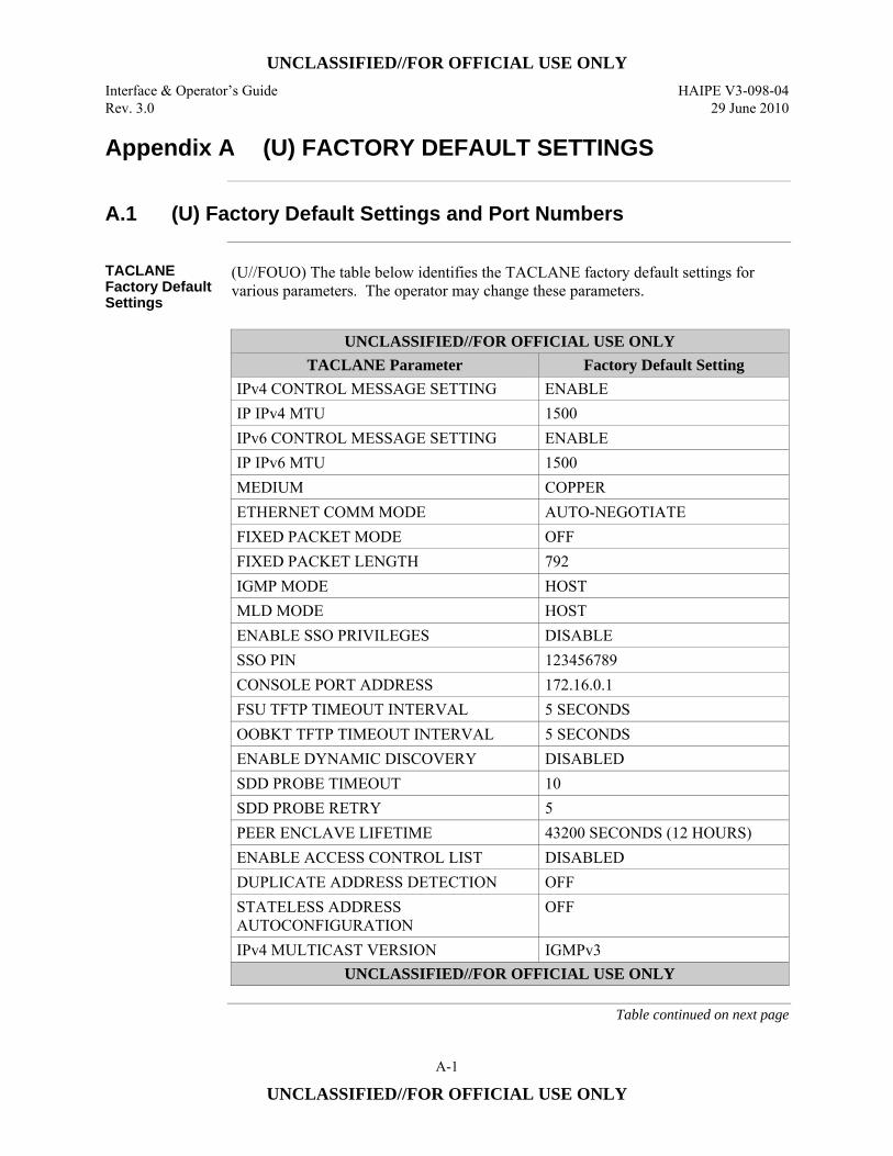
UNCLASSIFIED//FOR OFFICIAL USE ONLY
Interface & Operator’s Guide HAIPE V3-098-04 Rev. 3.0 29 June 2010
A-1
UNCLASSIFIED//FOR OFFICIAL USE ONLY
Appendix A (U) FACTORY DEFAULT SETTINGS
A.1 (U) Factory Default Settings and Port Numbers
TACLANE Factory Default Settings
(U//FOUO) The table below identifies the TACLANE factory default settings for various parameters. The operator may change these parameters.
UNCLASSIFIED//FOR OFFICIAL USE ONLY
TACLANE Parameter Factory Default Setting IPv4 CONTROL MESSAGE SETTING ENABLE IP IPv4 MTU 1500 IPv6 CONTROL MESSAGE SETTING ENABLE IP IPv6 MTU 1500 MEDIUM COPPER ETHERNET COMM MODE AUTO-NEGOTIATE FIXED PACKET MODE OFF FIXED PACKET LENGTH 792 IGMP MODE HOST MLD MODE HOST ENABLE SSO PRIVILEGES DISABLE SSO PIN 123456789 CONSOLE PORT ADDRESS 172.16.0.1 FSU TFTP TIMEOUT INTERVAL 5 SECONDS OOBKT TFTP TIMEOUT INTERVAL 5 SECONDS ENABLE DYNAMIC DISCOVERY DISABLED SDD PROBE TIMEOUT 10 SDD PROBE RETRY 5 PEER ENCLAVE LIFETIME 43200 SECONDS (12 HOURS) ENABLE ACCESS CONTROL LIST DISABLED DUPLICATE ADDRESS DETECTION OFF STATELESS ADDRESS AUTOCONFIGURATION
OFF
IPv4 MULTICAST VERSION IGMPv3 UNCLASSIFIED//FOR OFFICIAL USE ONLY
Table continued on next page
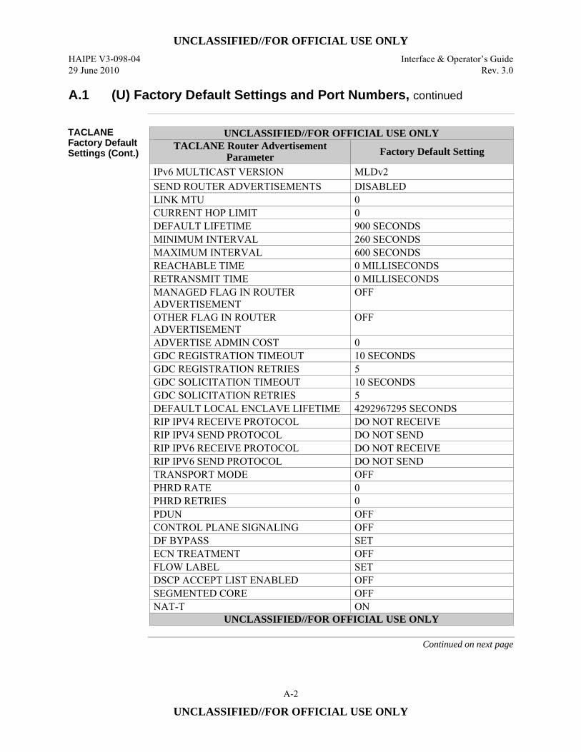
UNCLASSIFIED//FOR OFFICIAL USE ONLY
HAIPE V3-098-04 Interface & Operator’s Guide 29 June 2010 Rev. 3.0
A-2
UNCLASSIFIED//FOR OFFICIAL USE ONLY
A.1 (U) Factory Default Settings and Port Numbers, continued
TACLANE Factory Default Settings (Cont.)
UNCLASSIFIED//FOR OFFICIAL USE ONLY TACLANE Router Advertisement
Parameter Factory Default Setting
IPv6 MULTICAST VERSION MLDv2 SEND ROUTER ADVERTISEMENTS DISABLED LINK MTU 0 CURRENT HOP LIMIT 0 DEFAULT LIFETIME 900 SECONDS MINIMUM INTERVAL 260 SECONDS MAXIMUM INTERVAL 600 SECONDS REACHABLE TIME 0 MILLISECONDS RETRANSMIT TIME 0 MILLISECONDS MANAGED FLAG IN ROUTER ADVERTISEMENT
OFF
OTHER FLAG IN ROUTER ADVERTISEMENT
OFF
ADVERTISE ADMIN COST 0 GDC REGISTRATION TIMEOUT 10 SECONDS GDC REGISTRATION RETRIES 5 GDC SOLICITATION TIMEOUT 10 SECONDS GDC SOLICITATION RETRIES 5 DEFAULT LOCAL ENCLAVE LIFETIME 4292967295 SECONDS RIP IPV4 RECEIVE PROTOCOL DO NOT RECEIVE RIP IPV4 SEND PROTOCOL DO NOT SEND RIP IPV6 RECEIVE PROTOCOL DO NOT RECEIVE RIP IPV6 SEND PROTOCOL DO NOT SEND TRANSPORT MODE OFF PHRD RATE 0 PHRD RETRIES 0 PDUN OFF CONTROL PLANE SIGNALING OFF DF BYPASS SET ECN TREATMENT OFF FLOW LABEL SET DSCP ACCEPT LIST ENABLED OFF SEGMENTED CORE OFF NAT-T ON
UNCLASSIFIED//FOR OFFICIAL USE ONLY
Continued on next page
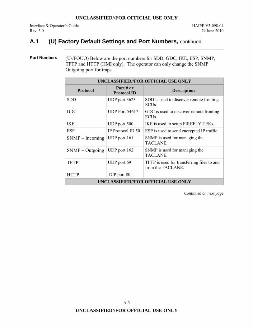
UNCLASSIFIED//FOR OFFICIAL USE ONLY
Interface & Operator’s Guide HAIPE V3-098-04 Rev. 3.0 29 June 2010
A-3
UNCLASSIFIED//FOR OFFICIAL USE ONLY
A.1 (U) Factory Default Settings and Port Numbers, continued
Port Numbers (U//FOUO) Below are the port numbers for SDD, GDC, IKE, ESP, SNMP,
TFTP and HTTP (HMI only). The operator can only change the SNMP Outgoing port for traps.
UNCLASSIFIED//FOR OFFICIAL USE ONLY
Protocol Port # or Protocol ID Description
SDD UDP port 3623 SDD is used to discover remote fronting ECUs.
GDC UDP Port 54617 GDC is used to discover remote fronting ECUs
IKE UDP port 500 IKE is used to setup FIREFLY TEKs. ESP IP Protocol ID 50 ESP is used to send encrypted IP traffic. SNMP – Incoming UDP port 161 SNMP is used for managing the
TACLANE. SNMP – Outgoing UDP port 162 SNMP is used for managing the
TACLANE. TFTP UDP port 69 TFTP is used for transferring files to and
from the TACLANE. HTTP TCP port 80
UNCLASSIFIED//FOR OFFICIAL USE ONLY
Continued on next page
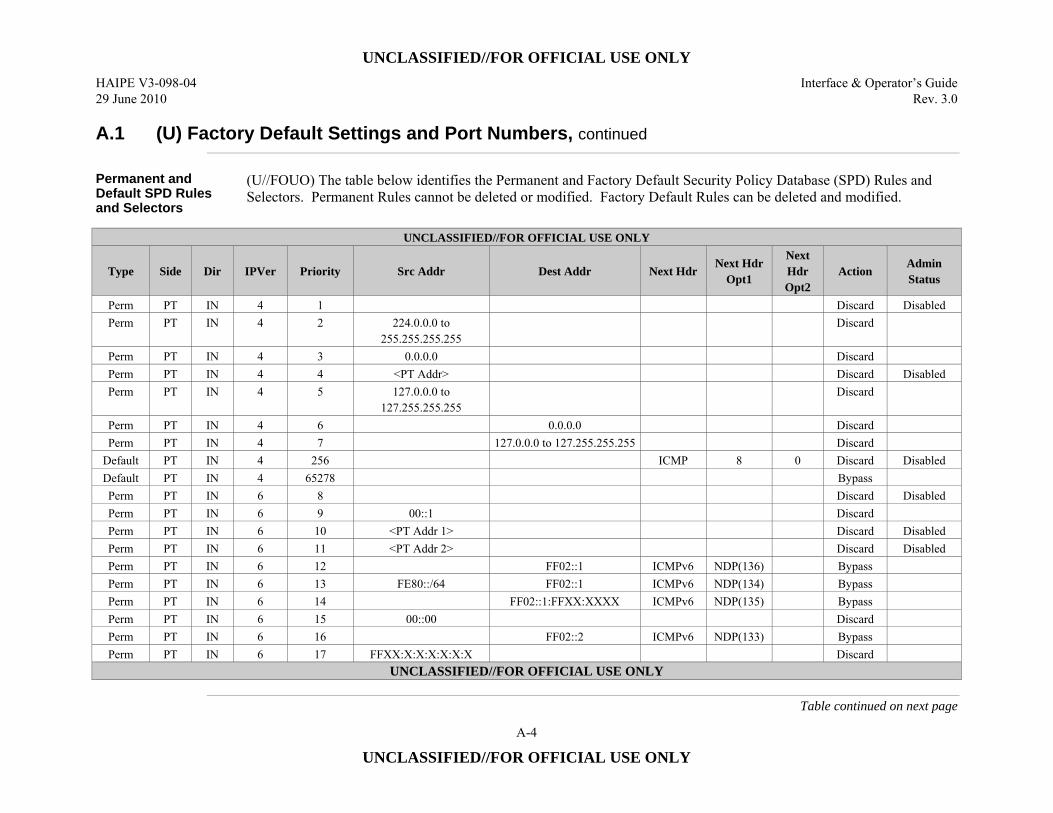
UNCLASSIFIED//FOR OFFICIAL USE ONLY
HAIPE V3-098-04 Interface & Operator’s Guide 29 June 2010 Rev. 3.0
A-4
UNCLASSIFIED//FOR OFFICIAL USE ONLY
A.1 (U) Factory Default Settings and Port Numbers, continued
Permanent and Default SPD Rules and Selectors
(U//FOUO) The table below identifies the Permanent and Factory Default Security Policy Database (SPD) Rules and Selectors. Permanent Rules cannot be deleted or modified. Factory Default Rules can be deleted and modified.
UNCLASSIFIED//FOR OFFICIAL USE ONLY
Type Side Dir IPVer Priority Src Addr Dest Addr Next Hdr Next Hdr
Opt1
Next Hdr Opt2
Action Admin Status
Perm PT IN 4 1 Discard Disabled Perm PT IN 4 2 224.0.0.0 to
255.255.255.255 Discard
Perm PT IN 4 3 0.0.0.0 Discard Perm PT IN 4 4 <PT Addr> Discard Disabled Perm PT IN 4 5 127.0.0.0 to
127.255.255.255 Discard
Perm PT IN 4 6 0.0.0.0 Discard Perm PT IN 4 7 127.0.0.0 to 127.255.255.255 Discard
Default PT IN 4 256 ICMP 8 0 Discard Disabled Default PT IN 4 65278 Bypass Perm PT IN 6 8 Discard Disabled Perm PT IN 6 9 00::1 Discard Perm PT IN 6 10 <PT Addr 1> Discard Disabled Perm PT IN 6 11 <PT Addr 2> Discard Disabled Perm PT IN 6 12 FF02::1 ICMPv6 NDP(136) Bypass Perm PT IN 6 13 FE80::/64 FF02::1 ICMPv6 NDP(134) Bypass Perm PT IN 6 14 FF02::1:FFXX:XXXX ICMPv6 NDP(135) Bypass Perm PT IN 6 15 00::00 Discard Perm PT IN 6 16 FF02::2 ICMPv6 NDP(133) Bypass Perm PT IN 6 17 FFXX:X:X:X:X:X:X Discard
UNCLASSIFIED//FOR OFFICIAL USE ONLY
Table continued on next page
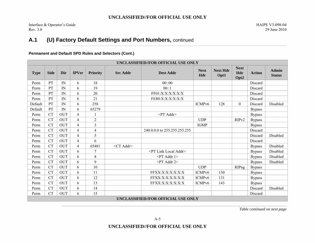
UNCLASSIFIED//FOR OFFICIAL USE ONLY
Interface & Operator’s Guide HAIPE V3-098-04 Rev. 3.0 29 June 2010
A-5
UNCLASSIFIED//FOR OFFICIAL USE ONLY
A.1 (U) Factory Default Settings and Port Numbers, continued
Permanent and Default SPD Rules and Selectors (Cont.)
UNCLASSIFIED//FOR OFFICIAL USE ONLY
Type Side Dir IPVer Priority Src Addr Dest Addr Next Hdr
Next Hdr Opt1
Next Hdr Opt2
Action Admin Status
Perm PT IN 6 18 00::00 Discard Perm PT IN 6 19 00::1 Discard Perm PT IN 6 20 FF01:X:X:X:X:X:X Discard Perm PT IN 6 21 FE80:X:X:X:X:X:X Discard
Default PT IN 6 258 ICMPv6 128 0 Discard Disabled Default PT IN 6 65279 Bypass Perm CT OUT 4 1 <PT Addr> Bypass Perm CT OUT 4 2 UDP RIPv2 Bypass Perm CT OUT 4 3 IGMP Bypass Perm CT OUT 4 4 240.0.0.0 to 255.255.255.255 Discard Perm CT OUT 4 5 Discard Disabled Perm CT OUT 4 6 Discard Perm CT OUT 4 65481 <CT Addr> Bypass Disabled Perm CT OUT 6 7 <PT Link Local Addr> Bypass Disabled Perm CT OUT 6 8 <PT Addr 1> Bypass Disabled Perm CT OUT 6 9 <PT Addr 2> Bypass Disabled Perm CT OUT 6 10 UDP RIPng Bypass Perm CT OUT 6 11 FFXX:X:X:X:X:X:X ICMPv6 130 Bypass Perm CT OUT 6 12 FFXX:X:X:X:X:X:X ICMPv6 131 Bypass Perm CT OUT 6 13 FFXX:X:X:X:X:X:X ICMPv6 143 Bypass Perm CT OUT 6 14 Discard Disabled Perm CT OUT 6 15 Discard
UNCLASSIFIED//FOR OFFICIAL USE ONLY
Table continued on next page
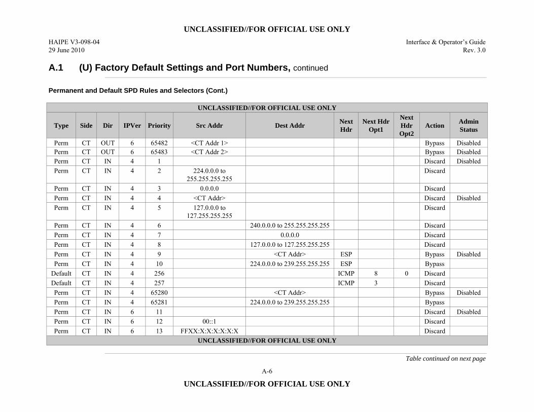
UNCLASSIFIED//FOR OFFICIAL USE ONLY
HAIPE V3-098-04 Interface & Operator’s Guide 29 June 2010 Rev. 3.0
A-6
UNCLASSIFIED//FOR OFFICIAL USE ONLY
A.1 (U) Factory Default Settings and Port Numbers, continued
Permanent and Default SPD Rules and Selectors (Cont.)
UNCLASSIFIED//FOR OFFICIAL USE ONLY
Type Side Dir IPVer Priority Src Addr Dest Addr Next Hdr
Next Hdr Opt1
Next Hdr Opt2
Action Admin Status
Perm CT OUT 6 65482 <CT Addr 1> Bypass Disabled Perm CT OUT 6 65483 <CT Addr 2> Bypass Disabled Perm CT IN 4 1 Discard Disabled Perm CT IN 4 2 224.0.0.0 to
255.255.255.255 Discard
Perm CT IN 4 3 0.0.0.0 Discard Perm CT IN 4 4 <CT Addr> Discard Disabled Perm CT IN 4 5 127.0.0.0 to
127.255.255.255 Discard
Perm CT IN 4 6 240.0.0.0 to 255.255.255.255 Discard Perm CT IN 4 7 0.0.0.0 Discard Perm CT IN 4 8 127.0.0.0 to 127.255.255.255 Discard Perm CT IN 4 9 <CT Addr> ESP Bypass Disabled Perm CT IN 4 10 224.0.0.0 to 239.255.255.255 ESP Bypass
Default CT IN 4 256 ICMP 8 0 Discard Default CT IN 4 257 ICMP 3 Discard Perm CT IN 4 65280 <CT Addr> Bypass Disabled Perm CT IN 4 65281 224.0.0.0 to 239.255.255.255 Bypass Perm CT IN 6 11 Discard Disabled Perm CT IN 6 12 00::1 Discard Perm CT IN 6 13 FFXX:X:X:X:X:X:X Discard
UNCLASSIFIED//FOR OFFICIAL USE ONLY
Table continued on next page
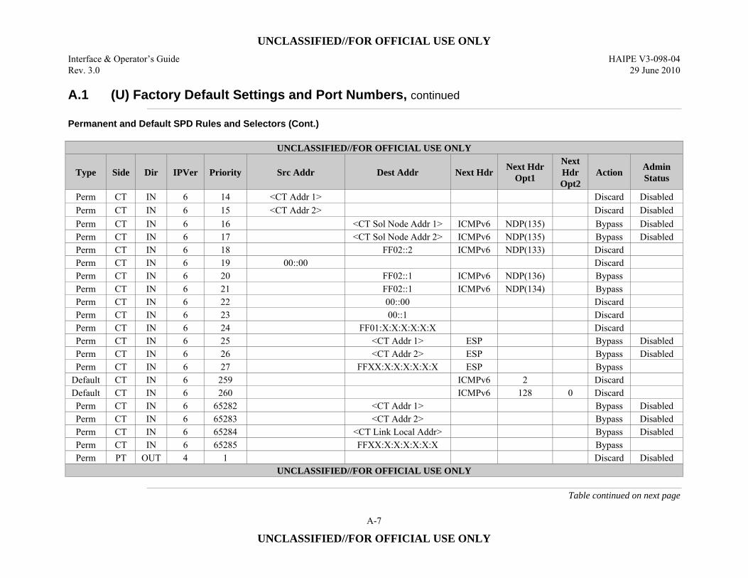
UNCLASSIFIED//FOR OFFICIAL USE ONLY
Interface & Operator’s Guide HAIPE V3-098-04 Rev. 3.0 29 June 2010
A-7
UNCLASSIFIED//FOR OFFICIAL USE ONLY
A.1 (U) Factory Default Settings and Port Numbers, continued
Permanent and Default SPD Rules and Selectors (Cont.)
UNCLASSIFIED//FOR OFFICIAL USE ONLY
Type Side Dir IPVer Priority Src Addr Dest Addr Next Hdr Next Hdr Opt1
Next Hdr Opt2
Action Admin Status
Perm CT IN 6 14 <CT Addr 1> Discard Disabled Perm CT IN 6 15 <CT Addr 2> Discard Disabled Perm CT IN 6 16 <CT Sol Node Addr 1> ICMPv6 NDP(135) Bypass Disabled Perm CT IN 6 17 <CT Sol Node Addr 2> ICMPv6 NDP(135) Bypass Disabled Perm CT IN 6 18 FF02::2 ICMPv6 NDP(133) Discard Perm CT IN 6 19 00::00 Discard Perm CT IN 6 20 FF02::1 ICMPv6 NDP(136) Bypass Perm CT IN 6 21 FF02::1 ICMPv6 NDP(134) Bypass Perm CT IN 6 22 00::00 Discard Perm CT IN 6 23 00::1 Discard Perm CT IN 6 24 FF01:X:X:X:X:X:X Discard Perm CT IN 6 25 <CT Addr 1> ESP Bypass Disabled Perm CT IN 6 26 <CT Addr 2> ESP Bypass Disabled Perm CT IN 6 27 FFXX:X:X:X:X:X:X ESP Bypass
Default CT IN 6 259 ICMPv6 2 Discard Default CT IN 6 260 ICMPv6 128 0 Discard Perm CT IN 6 65282 <CT Addr 1> Bypass Disabled Perm CT IN 6 65283 <CT Addr 2> Bypass Disabled Perm CT IN 6 65284 <CT Link Local Addr> Bypass Disabled Perm CT IN 6 65285 FFXX:X:X:X:X:X:X Bypass Perm PT OUT 4 1 Discard Disabled
UNCLASSIFIED//FOR OFFICIAL USE ONLY
Table continued on next page
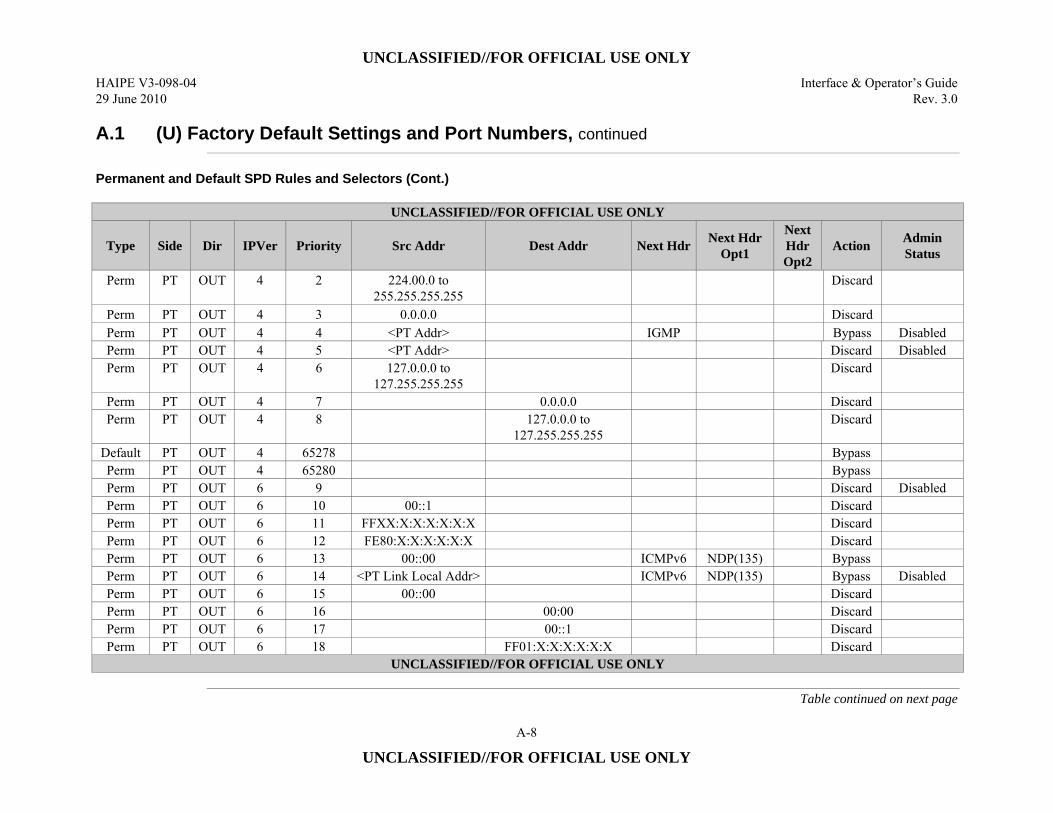
UNCLASSIFIED//FOR OFFICIAL USE ONLY
HAIPE V3-098-04 Interface & Operator’s Guide 29 June 2010 Rev. 3.0
A-8
UNCLASSIFIED//FOR OFFICIAL USE ONLY
A.1 (U) Factory Default Settings and Port Numbers, continued
Permanent and Default SPD Rules and Selectors (Cont.)
UNCLASSIFIED//FOR OFFICIAL USE ONLY
Type Side Dir IPVer Priority Src Addr Dest Addr Next Hdr Next Hdr Opt1
Next Hdr Opt2
Action Admin Status
Perm PT OUT 4 2 224.00.0 to 255.255.255.255
Discard
Perm PT OUT 4 3 0.0.0.0 Discard Perm PT OUT 4 4 <PT Addr> IGMP Bypass Disabled Perm PT OUT 4 5 <PT Addr> Discard Disabled Perm PT OUT 4 6 127.0.0.0 to
127.255.255.255 Discard
Perm PT OUT 4 7 0.0.0.0 Discard Perm PT OUT 4 8 127.0.0.0 to
127.255.255.255 Discard
Default PT OUT 4 65278 Bypass Perm PT OUT 4 65280 Bypass Perm PT OUT 6 9 Discard Disabled Perm PT OUT 6 10 00::1 Discard Perm PT OUT 6 11 FFXX:X:X:X:X:X:X Discard Perm PT OUT 6 12 FE80:X:X:X:X:X:X Discard Perm PT OUT 6 13 00::00 ICMPv6 NDP(135) Bypass Perm PT OUT 6 14 <PT Link Local Addr> ICMPv6 NDP(135) Bypass Disabled Perm PT OUT 6 15 00::00 Discard Perm PT OUT 6 16 00:00 Discard Perm PT OUT 6 17 00::1 Discard Perm PT OUT 6 18 FF01:X:X:X:X:X:X Discard
UNCLASSIFIED//FOR OFFICIAL USE ONLY
Table continued on next page
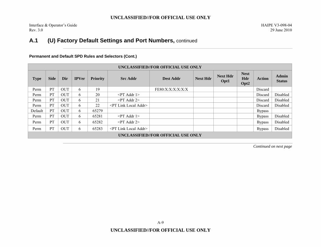
UNCLASSIFIED//FOR OFFICIAL USE ONLY
Interface & Operator’s Guide HAIPE V3-098-04 Rev. 3.0 29 June 2010
A-9
UNCLASSIFIED//FOR OFFICIAL USE ONLY
A.1 (U) Factory Default Settings and Port Numbers, continued
Permanent and Default SPD Rules and Selectors (Cont.)
UNCLASSIFIED//FOR OFFICIAL USE ONLY
Type Side Dir IPVer Priority Src Addr Dest Addr Next Hdr Next Hdr Opt1
Next Hdr Opt2
Action Admin Status
Perm PT OUT 6 19 FE80:X:X:X:X:X:X Discard Perm PT OUT 6 20 <PT Addr 1> Discard Disabled Perm PT OUT 6 21 <PT Addr 2> Discard Disabled Perm PT OUT 6 22 <PT Link Local Addr> Discard Disabled
Default PT OUT 6 65279 Bypass Perm PT OUT 6 65281 <PT Addr 1> Bypass Disabled Perm PT OUT 6 65282 <PT Addr 2> Bypass Disabled Perm PT OUT 6 65283 <PT Link Local Addr> Bypass Disabled
UNCLASSIFIED//FOR OFFICIAL USE ONLY
Continued on next page
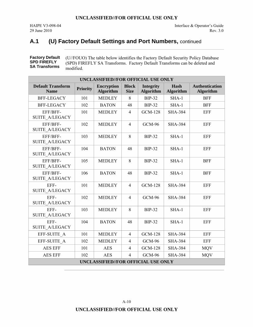
UNCLASSIFIED//FOR OFFICIAL USE ONLY
HAIPE V3-098-04 Interface & Operator’s Guide 29 June 2010 Rev. 3.0
A-10
UNCLASSIFIED//FOR OFFICIAL USE ONLY
A.1 (U) Factory Default Settings and Port Numbers, continued
Factory Default SPD FIREFLY SA Transforms
(U//FOUO) The table below identifies the Factory Default Security Policy Database (SPD) FIREFLY SA Transforms. Factory Default Transforms can be deleted and modified.
UNCLASSIFIED//FOR OFFICIAL USE ONLY
Default Transform Name Priority Encryption
Algorithm Block Size
Integrity Algorithm
Hash Algorithm
Authentication Algorithm
BFF-LEGACY 101 MEDLEY 8 BIP-32 SHA-1 BFF BFF-LEGACY 102 BATON 48 BIP-32 SHA-1 BFF
EFF/BFF-SUITE_A/LEGACY
101 MEDLEY 4 GCM-128 SHA-384 EFF
EFF/BFF-SUITE_A/LEGACY
102 MEDLEY 4 GCM-96 SHA-384 EFF
EFF/BFF-SUITE_A/LEGACY
103 MEDLEY 8 BIP-32 SHA-1 EFF
EFF/BFF-SUITE_A/LEGACY
104 BATON 48 BIP-32 SHA-1 EFF
EFF/BFF-SUITE_A/LEGACY
105 MEDLEY 8 BIP-32 SHA-1 BFF
EFF/BFF-SUITE_A/LEGACY
106 BATON 48 BIP-32 SHA-1 BFF
EFF-SUITE_A/LEGACY
101 MEDLEY 4 GCM-128 SHA-384 EFF
EFF-SUITE_A/LEGACY
102 MEDLEY 4 GCM-96 SHA-384 EFF
EFF-SUITE_A/LEGACY
103 MEDLEY 8 BIP-32 SHA-1 EFF
EFF-SUITE_A/LEGACY
104 BATON 48 BIP-32 SHA-1 EFF
EFF-SUITE_A 101 MEDLEY 4 GCM-128 SHA-384 EFF EFF-SUITE_A 102 MEDLEY 4 GCM-96 SHA-384 EFF
AES EFF 101 AES 4 GCM-128 SHA-384 MQV AES EFF 102 AES 4 GCM-96 SHA-384 MQV
UNCLASSIFIED//FOR OFFICIAL USE ONLY
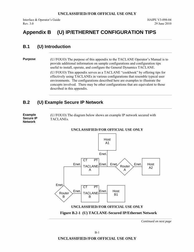
UNCLASSIFIED//FOR OFFICIAL USE ONLY
Interface & Operator’s Guide HAIPE V3-098-04 Rev. 3.0 29 June 2010
B-1
UNCLASSIFIED//FOR OFFICIAL USE ONLY
Appendix B (U) IP/ETHERNET CONFIGURATION TIPS
B.1 (U) Introduction
Purpose (U//FOUO) The purpose of this appendix to the TACLANE Operator’s Manual is to
provide additional information on sample configurations and configuration tips useful to install, operate, and configure the General Dynamics TACLANE. (U//FOUO) This appendix serves as a TACLANE “cookbook” by offering tips for effectively using TACLANEs in various configurations that resemble typical user environments. The configurations described here are examples to illustrate the concepts involved. There may be other configurations that are equivalent to those described in this appendix.
B.2 (U) Example Secure IP Network
Example Secure IP Network
(U//FOUO) The diagram below shows an example IP network secured with TACLANEs.
UNCLASSIFIED//FOR OFFICIAL USE ONLY
TACLANEA
CT PTEnet. Enet.
Enet.
RouterA
Enet. Host A2
HostA1
Enet.
Router B
TACLANEB
CT PTEnet. Host
B1Enet.
Enet.
UNCLASSIFIED//FOR OFFICIAL USE ONLY
Figure B.2-1 (U) TACLANE-Secured IP/Ethernet Network
Continued on next page
UNCLASSIFIED//FOR OFFICIAL USE ONLY
HAIPE V3-098-04 Interface & Operator’s Guide 29 June 2010 Rev. 3.0
B-2
UNCLASSIFIED//FOR OFFICIAL USE ONLY
B.2 (U) Example Secure IP Network, continued
Example Secure IP Network (Cont.)
(U//FOUO) Router B represents the CT IP network. Router A, Host A1, Host A2, and Host B1 represent the protected PT IP network. TACLANE A fronts Host A1, Router A, and Host A2. TACLANE B fronts Host B1. (U//FOUO) The TACLANEs secure IP datagram traffic traveling between them.
B.3 (U) General IP/Ethernet Configuration Tips
Introduction (U//FOUO) Listed below are some general TACLANE IP configuration tips.
Single CT Default Gateway
(U//FOUO) Any outgoing CT IP datagrams that have a destination IP address that is off the local IP network/subnetwork are statically routed to the CT default gateway if configured. (U//FOUO) If the optional CT default gateway is not configured, the TACLANE ARPs for all destination IP addresses for outgoing CT IP datagram traffic. With this configuration, ARP enhancements allow multiple CT gateways – assuming proxy-ARP support on all CT gateways.
Single PT Default Gateway
(U//FOUO) Any outgoing PT IP datagrams that have a destination IP address that is off of the local IP network/subnetwork are statically routed to the PT default gateway if configured. (U//FOUO) If the optional PT default gateway is not configured, the TACLANE ARPs for all destination IP addresses for outgoing PT IP datagram traffic. With this configuration, ARP enhancements allow multiple PT gateways – assuming proxy-ARP support on all PT gateways.
Continued on next page
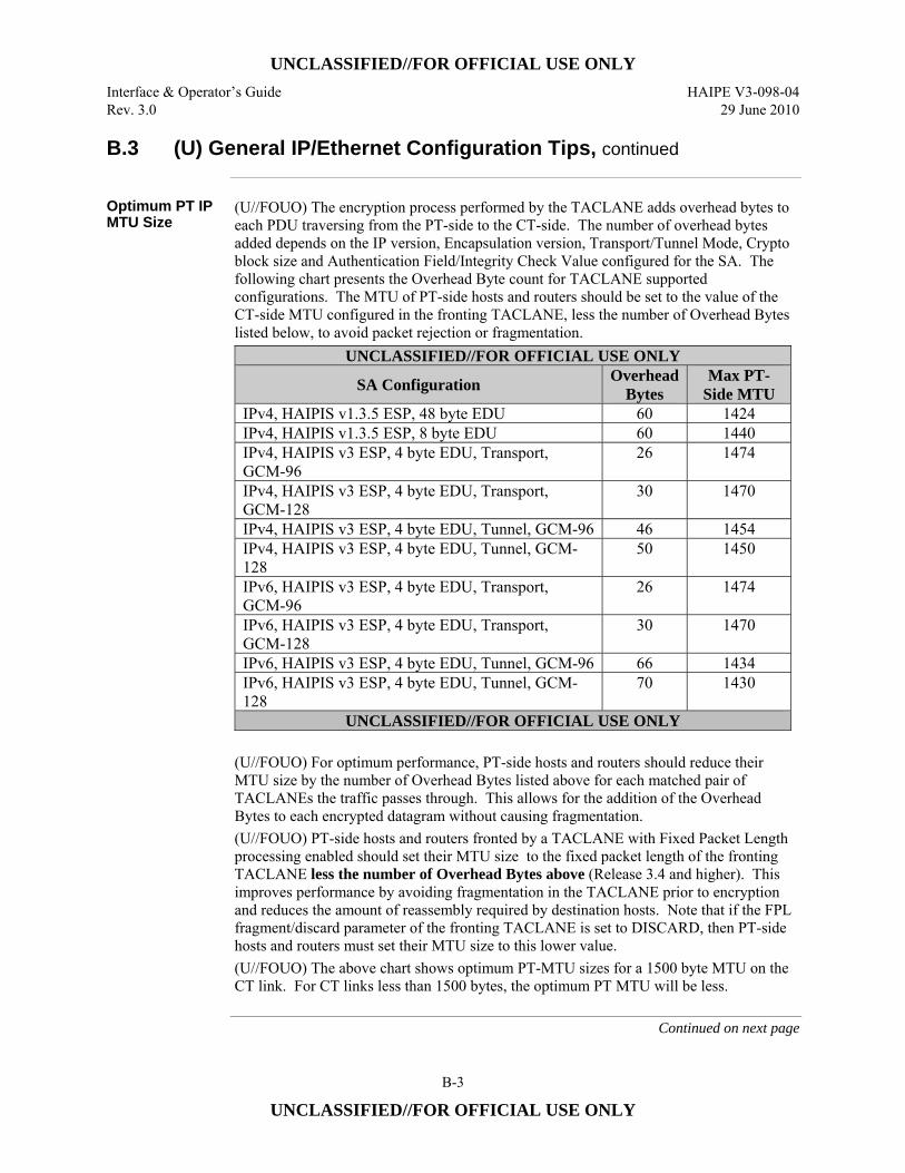
UNCLASSIFIED//FOR OFFICIAL USE ONLY
Interface & Operator’s Guide HAIPE V3-098-04 Rev. 3.0 29 June 2010
B-3
UNCLASSIFIED//FOR OFFICIAL USE ONLY
B.3 (U) General IP/Ethernet Configuration Tips, continued
Optimum PT IP MTU Size
(U//FOUO) The encryption process performed by the TACLANE adds overhead bytes to each PDU traversing from the PT-side to the CT-side. The number of overhead bytes added depends on the IP version, Encapsulation version, Transport/Tunnel Mode, Crypto block size and Authentication Field/Integrity Check Value configured for the SA. The following chart presents the Overhead Byte count for TACLANE supported configurations. The MTU of PT-side hosts and routers should be set to the value of the CT-side MTU configured in the fronting TACLANE, less the number of Overhead Bytes listed below, to avoid packet rejection or fragmentation.
UNCLASSIFIED//FOR OFFICIAL USE ONLY
SA Configuration Overhead Bytes
Max PT-Side MTU
IPv4, HAIPIS v1.3.5 ESP, 48 byte EDU 60 1424 IPv4, HAIPIS v1.3.5 ESP, 8 byte EDU 60 1440 IPv4, HAIPIS v3 ESP, 4 byte EDU, Transport, GCM-96
26 1474
IPv4, HAIPIS v3 ESP, 4 byte EDU, Transport, GCM-128
30 1470
IPv4, HAIPIS v3 ESP, 4 byte EDU, Tunnel, GCM-96 46 1454 IPv4, HAIPIS v3 ESP, 4 byte EDU, Tunnel, GCM-128
50 1450
IPv6, HAIPIS v3 ESP, 4 byte EDU, Transport, GCM-96
26 1474
IPv6, HAIPIS v3 ESP, 4 byte EDU, Transport, GCM-128
30 1470
IPv6, HAIPIS v3 ESP, 4 byte EDU, Tunnel, GCM-96 66 1434 IPv6, HAIPIS v3 ESP, 4 byte EDU, Tunnel, GCM-128
70 1430
UNCLASSIFIED//FOR OFFICIAL USE ONLY (U//FOUO) For optimum performance, PT-side hosts and routers should reduce their MTU size by the number of Overhead Bytes listed above for each matched pair of TACLANEs the traffic passes through. This allows for the addition of the Overhead Bytes to each encrypted datagram without causing fragmentation. (U//FOUO) PT-side hosts and routers fronted by a TACLANE with Fixed Packet Length processing enabled should set their MTU size to the fixed packet length of the fronting TACLANE less the number of Overhead Bytes above (Release 3.4 and higher). This improves performance by avoiding fragmentation in the TACLANE prior to encryption and reduces the amount of reassembly required by destination hosts. Note that if the FPL fragment/discard parameter of the fronting TACLANE is set to DISCARD, then PT-side hosts and routers must set their MTU size to this lower value. (U//FOUO) The above chart shows optimum PT-MTU sizes for a 1500 byte MTU on the CT link. For CT links less than 1500 bytes, the optimum PT MTU will be less.
Continued on next page
UNCLASSIFIED//FOR OFFICIAL USE ONLY
HAIPE V3-098-04 Interface & Operator’s Guide 29 June 2010 Rev. 3.0
B-4
UNCLASSIFIED//FOR OFFICIAL USE ONLY
B.3 (U) General IP/Ethernet Configuration Tips, continued
Multicast IP Datagram Support
(U//FOUO) TACLANE allows PPKs to be assigned to Class D addresses in support of IP multicast. (U//FOUO) PT multicast traffic is encrypted and sent to the same multicast address. (U//FOUO) TACLANE does not support the use of the TTL field to limit the scope of multicast IP datagram traffic.
TACLANE Nesting
(U//FOUO) TACLANE nesting, up to three pairs deep, is supported for IP over Ethernet. Nested configurations using three pairs of TACLANEs have been tested, but three is not a hard limit.
Auto-recovery (U//FOUO) If the TACLANE is turned off, or prime power fails, while processing
user traffic, the TACLANE performs autorecovery when power is restored and automatically returns to processing user traffic: • Security associations reestablish automatically without operator intervention.
PPK Takes Precedence Over FIREFLY
(U//FOUO) For security associations, a PPK assignment takes precedence over generating a FIREFLY TEK.
Firewalls Must Pass SDD, IKE, and ESP
(U//FOUO) Any firewalls in the path between communicating TACLANEs must be configured to pass SDD, IKE, and ESP. See the Operator’s Manual section on “Factory Default Settings and Port Numbers” for the port numbers for these protocols.
ARP Cache Flushing
(U//FOUO) If the TACLANE was inserted into an existing IP/Ethernet configuration, flush the ARP caches on hosts and routers before putting the TACLANE online. To flush TACLANE’s ARP cache, reset the TACLANE.
Continued on next page
UNCLASSIFIED//FOR OFFICIAL USE ONLY
Interface & Operator’s Guide HAIPE V3-098-04 Rev. 3.0 29 June 2010
B-5
UNCLASSIFIED//FOR OFFICIAL USE ONLY
B.3 (U) General IP/Ethernet Configuration Tips, continued
Automated Peer TACLANE Discovery
(U//FOUO) TACLANEs support automated peer TACLANE discovery for security associations, through the HAIPE IS Secure Dynamic Discovery (SDD) protocol. Once a peer TACLANE is identified, the following occurs: • (U//FOUO) PPK assignments are checked for a match based on the remote
TACLANE IP address. If a match is found, the corresponding PPK is used to secure the IP traffic.
• (U//FOUO) Existing security associations using FIREFLY TEKs are checked for a match based on the remote TACLANE IP address. If a match is found, the corresponding existing security association (using a FIREFLY TEK) is used to secure the IP traffic.
(U//FOUO) If there is no matching PPK assignment or security association (using a FIREFLY TEK), and an operational FIREFLY vector set is usable at the current security level, the following occurs: • (U//FOUO) A new security association is created and the initiator and responder
peer TACLANEs cooperatively generate a FIREFLY TEK using their FIREFLY vector sets.
(U//FOUO) Automated peer TACLANE discovery may be inhibited using PPKs. See the chapter on “Configuring/Managing Security Associations.” (U//FOUO) If automated peer TACLANE discovery is not desirable, remote TACLANE static routes can be defined. (See the section in the Operator’s Manual titled “Configuring Remote TACLANE Static Routing.”)
PT Proxy-ARP Support
(U//FOUO) TACLANE proxy-ARP replies to an ARP request received by the PT interface when the target address is covered by a static routing table entry. TACLANE will not proxy-ARP reply to a PT host based solely on a default route. The target IP address in the PT ARP request must be covered by a static routing table entry other than the default route.
Continued on next page
UNCLASSIFIED//FOR OFFICIAL USE ONLY
HAIPE V3-098-04 Interface & Operator’s Guide 29 June 2010 Rev. 3.0
B-6
UNCLASSIFIED//FOR OFFICIAL USE ONLY
B.3 (U) General IP/Ethernet Configuration Tips, continued
Remote TACLANE Static Routing Table
(U//FOUO) The operator may define a remote TACLANE routing table to associate destination IP networks/subnetworks with remote TACLANEs: • (U//FOUO) Up to 1024 IP network/subnetwork destination entries may be
defined. Entries are pooled; a maximum of 1024 entries may be created across all security levels. (The sum total of all entries at all security levels must be less than or equal to 1024).
• (U//FOUO) Entries consist of a remote TACLANE IP address, destination network ID, and prefix length.
• (U//FOUO) Routes for the local TACLANE may be included. This allows the same remote TACLANE routing table to be used in every TACLANE. It is recommended that these routes be included when a CT default route is also defined.
• (U//FOUO) Multiple destination IP networks/subnetworks may be associated with the same remote TACLANE IP address.
• (U//FOUO) One default route TACLANE table entry may be defined by identifying the network ID and prefix length as 0.0.0.0/0.
• (U//FOUO) Validation checks on table entries include: – Prefix length must be valid for the network ID. – No duplicate table entries (no two entries with the same network ID and
prefix length). (The same network ID may be defined in multiple entries as long as the prefix lengths are different.)
• (U//FOUO) A “longest match” search of the table based on combination of network ID and prefix length is used to determine the remote TACLANE to which the IP traffic should be sent.
• (U//FOUO) GEM X can also configure the routing table. One routing table can be generated by the GEM X and distributed to all the TACLANEs.
PT Default Gateway or ARP Used to Deliver PT IP Traffic
(U//FOUO) If the optional PT default gateway IP address is configured, all off-net decrypted PT IP traffic will be delivered to the PT default gateway. (U//FOUO) If the optional PT default gateway is not configured, TACLANE will ARP for all off-net destination IP addresses for decrypted PT IP traffic. (U//FOUO) Assumes proxy-ARP support in PT routers. Proxy-ARP allows a router to reply to a received ARP request for a host in a network that is in the router’s routing table.
Continued on next page
UNCLASSIFIED//FOR OFFICIAL USE ONLY
Interface & Operator’s Guide HAIPE V3-098-04 Rev. 3.0 29 June 2010
B-7
UNCLASSIFIED//FOR OFFICIAL USE ONLY
B.3 (U) General IP/Ethernet Configuration Tips, continued
CT Default Gateway or ARP Used to Deliver CT IP Traffic
(U//FOUO) If the optional CT default gateway IP address is configured, all off-net encrypted CT IP traffic will be delivered to the CT default gateway. (U//FOUO) If the optional CT default gateway is not configured, TACLANE will ARP for all off-net destination IP addresses for encrypted CT IP traffic. (U//FOUO) Assumes proxy-ARP support in CT routers. Proxy-ARP allows a router to reply to a received ARP request for a host in a network that is in the router’s routing table. (U//FOUO) When a CT default gateway is defined, it is recommended that a route for the local TL-protected network also be included in the static routing table.
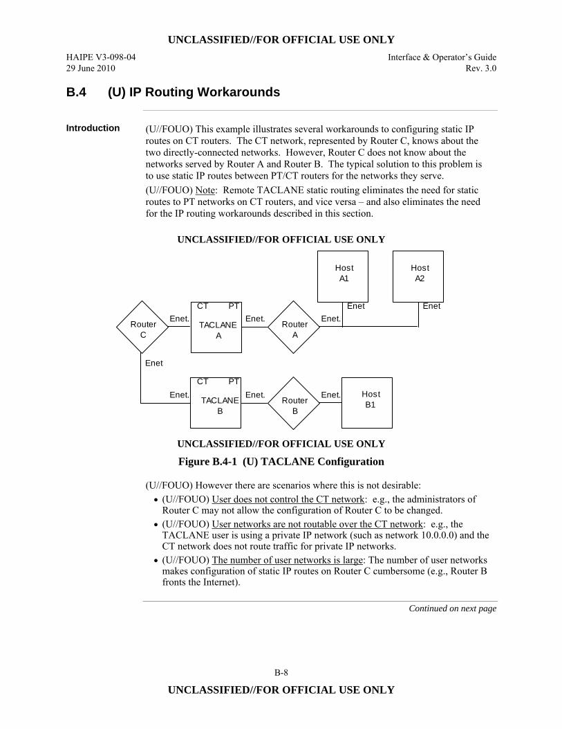
UNCLASSIFIED//FOR OFFICIAL USE ONLY
HAIPE V3-098-04 Interface & Operator’s Guide 29 June 2010 Rev. 3.0
B-8
UNCLASSIFIED//FOR OFFICIAL USE ONLY
B.4 (U) IP Routing Workarounds
Introduction (U//FOUO) This example illustrates several workarounds to configuring static IP
routes on CT routers. The CT network, represented by Router C, knows about the two directly-connected networks. However, Router C does not know about the networks served by Router A and Router B. The typical solution to this problem is to use static IP routes between PT/CT routers for the networks they serve. (U//FOUO) Note: Remote TACLANE static routing eliminates the need for static routes to PT networks on CT routers, and vice versa – and also eliminates the need for the IP routing workarounds described in this section.
UNCLASSIFIED//FOR OFFICIAL USE ONLY
HostA1
TACLANEA
CT PTEnet.Enet.
RouterC
TACLANEB
HostB1
CT PT
HostA2
Enet Enet
Enet.Enet.
Enet
Enet.Router
A
Enet.Router
B
UNCLASSIFIED//FOR OFFICIAL USE ONLY
Figure B.4-1 (U) TACLANE Configuration (U//FOUO) However there are scenarios where this is not desirable:
• (U//FOUO) User does not control the CT network: e.g., the administrators of Router C may not allow the configuration of Router C to be changed.
• (U//FOUO) User networks are not routable over the CT network: e.g., the TACLANE user is using a private IP network (such as network 10.0.0.0) and the CT network does not route traffic for private IP networks.
• (U//FOUO) The number of user networks is large: The number of user networks makes configuration of static IP routes on Router C cumbersome (e.g., Router B fronts the Internet).
Continued on next page
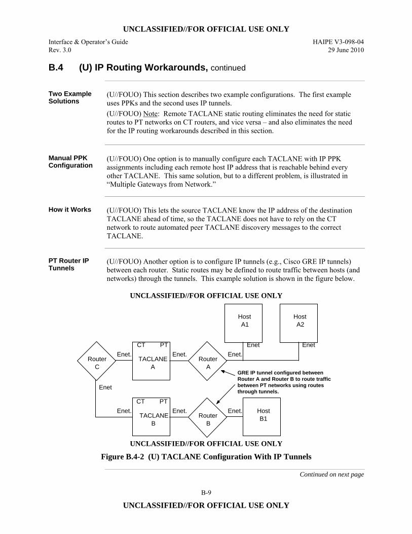
UNCLASSIFIED//FOR OFFICIAL USE ONLY
Interface & Operator’s Guide HAIPE V3-098-04 Rev. 3.0 29 June 2010
B-9
UNCLASSIFIED//FOR OFFICIAL USE ONLY
B.4 (U) IP Routing Workarounds, continued
Two Example Solutions
(U//FOUO) This section describes two example configurations. The first example uses PPKs and the second uses IP tunnels. (U//FOUO) Note: Remote TACLANE static routing eliminates the need for static routes to PT networks on CT routers, and vice versa – and also eliminates the need for the IP routing workarounds described in this section.
Manual PPK Configuration
(U//FOUO) One option is to manually configure each TACLANE with IP PPK assignments including each remote host IP address that is reachable behind every other TACLANE. This same solution, but to a different problem, is illustrated in “Multiple Gateways from Network.”
How it Works (U//FOUO) This lets the source TACLANE know the IP address of the destination
TACLANE ahead of time, so the TACLANE does not have to rely on the CT network to route automated peer TACLANE discovery messages to the correct TACLANE.
PT Router IP Tunnels
(U//FOUO) Another option is to configure IP tunnels (e.g., Cisco GRE IP tunnels) between each router. Static routes may be defined to route traffic between hosts (and networks) through the tunnels. This example solution is shown in the figure below.
UNCLASSIFIED//FOR OFFICIAL USE ONLY
HostA1
TACLANEA
CT PTEnet.Enet.
RouterC
TACLANEB
HostB1
CT PT
HostA2
Enet Enet
Enet.Enet.
Enet
Enet.Router
A
Enet.Router
B
GRE IP tunnel configured between Router A and Router B to route traffic between PT networks using routes through tunnels.
UNCLASSIFIED//FOR OFFICIAL USE ONLY
Figure B.4-2 (U) TACLANE Configuration With IP Tunnels
Continued on next page
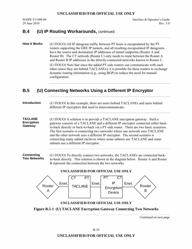
UNCLASSIFIED//FOR OFFICIAL USE ONLY
HAIPE V3-098-04 Interface & Operator’s Guide 29 June 2010 Rev. 3.0
B-10
UNCLASSIFIED//FOR OFFICIAL USE ONLY
B.4 (U) IP Routing Workarounds, continued
How it Works (U//FOUO) All IP datagram traffic between PT hosts is encapsulated by the PT
routers supporting the GRE IP tunnels, and all resulting encapsulated IP datagrams have the source and destination IP addresses of tunnel endpoints (Router A and Router B). The CT network (Router C) only needs to route between the Router A and Router B IP addresses in the directly-connected networks known to Router C. (U//FOUO) Note that since the added PT-side routers can communicate with each other (since they are behind TACLANEs), it is possible for these routers to exchange dynamic routing information (e.g., using BGP) to reduce the need for manual configuration.
B.5 (U) Connecting Networks Using a Different IP Encryptor
Introduction (U//FOUO) In this example, there are users behind TACLANEs and users behind
different IP encryptors that need to intercommunicate.
TACLANE Encryption Gateway
(U//FOUO) A solution is to provide a TACLANE encryption gateway. Such a gateway consists of a TACLANE and a different IP encryptor connected either back-to-back directly or back-to-back via a PT-side router. There are two basic scenarios. The first scenario is connecting two networks where one network uses TACLANE and the other network uses a different IP encryptor. The second scenario is connecting many subnet enclaves where some subnets use TACLANE and some subnets use a different IP encryptor.
Connecting Two Networks
(U//FOUO) To directly connect two networks, the TACLANEs are connected back-to-back directly. This solution is shown in the diagram below. Router A and Router B represent the connection between the two networks.
UNCLASSIFIED//FOR OFFICIAL USE ONLY
TACLANE
CT PTEnet.Enet.Router
A
IPEncryption
Device
PT CTEnet. Router
B
UNCLASSIFIED//FOR OFFICIAL USE ONLY
Figure B.5-1 (U) TACLANE Encryption Gateway Connecting Two Networks
Continued on next page
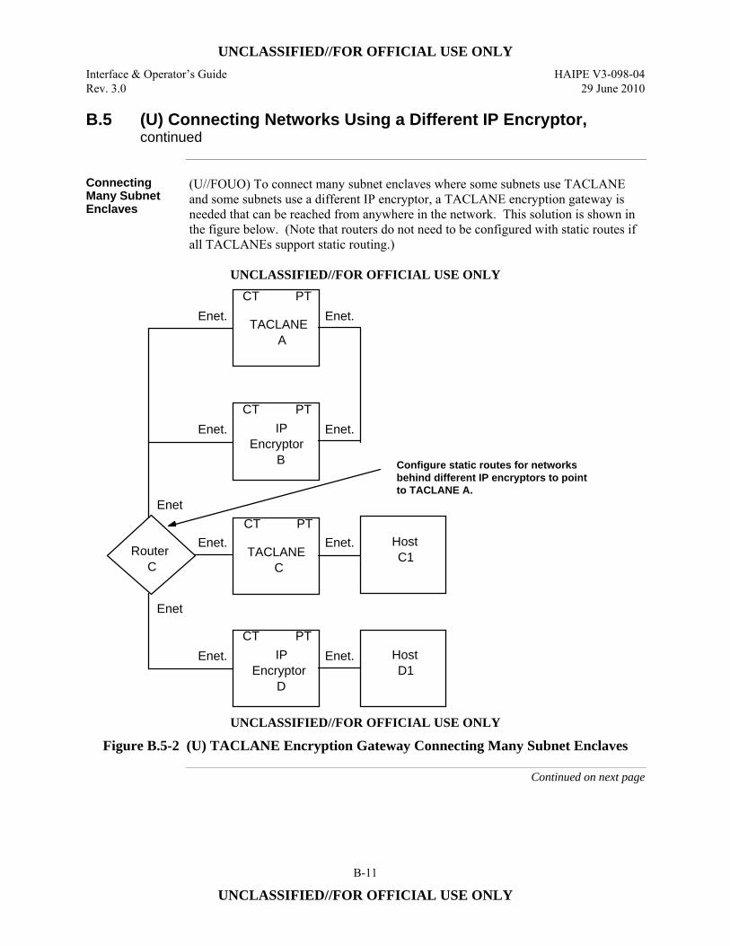
UNCLASSIFIED//FOR OFFICIAL USE ONLY
Interface & Operator’s Guide HAIPE V3-098-04 Rev. 3.0 29 June 2010
B-11
UNCLASSIFIED//FOR OFFICIAL USE ONLY
B.5 (U) Connecting Networks Using a Different IP Encryptor, continued
Connecting Many Subnet Enclaves
(U//FOUO) To connect many subnet enclaves where some subnets use TACLANE and some subnets use a different IP encryptor, a TACLANE encryption gateway is needed that can be reached from anywhere in the network. This solution is shown in the figure below. (Note that routers do not need to be configured with static routes if all TACLANEs support static routing.)
UNCLASSIFIED//FOR OFFICIAL USE ONLY
TACLANEC
CT PTEnet.Enet.
RouterC
IPEncryptor
D
HostD1
CT PTEnet.Enet.
Enet
IPEncryptor
B
CT PTEnet.Enet.
Enet
TACLANEA
CT PTEnet.Enet.
HostC1
Configure static routes for networks behind different IP encryptors to point to TACLANE A.
UNCLASSIFIED//FOR OFFICIAL USE ONLY
Figure B.5-2 (U) TACLANE Encryption Gateway Connecting Many Subnet Enclaves
Continued on next page
UNCLASSIFIED//FOR OFFICIAL USE ONLY
HAIPE V3-098-04 Interface & Operator’s Guide 29 June 2010 Rev. 3.0
B-12
UNCLASSIFIED//FOR OFFICIAL USE ONLY
B.5 (U) Connecting Networks Using a Different IP Encryptor, continued
Connecting Many Subnet Enclaves (Cont.)
(U//FOUO) The CT network represented by Router C requires at least a static route for the network behind IP Encryptor D to point to TACLANE A. This is needed to route automated peer discovery messages to the correct TACLANE. The routing configuration may need further modification depending on the nature of the different IP encryptor. Note that this solution can be augmented with the solutions from “IP Routing Workarounds”, or static routing capabilities.
How it Works (U//FOUO) In both scenarios, the TACLANE encryption gateway works by having
the different IP encryptor decrypt IP datagram traffic before it is encrypted again by the TACLANE, and vice versa.
B.6 (U) Connecting Networks at Different Security Levels
Introduction (U//FOUO) In this example, there are two base networks, one Secret and one
Unclassified. In order to share network infrastructure and provide flexibility, administrators need to deploy Secret hosts on the Unclassified network, deploy Unclassified hosts on the Secret network, and allow all hosts to communicate with their respective base networks. (U//FOUO) Note: Remote TACLANE static routing eliminates the need for static routes to PT networks on CT routers, and vice versa – and may greatly simplify the configurations described in this section.
Two Example Configurations
(U//FOUO) This section describes two example configurations of TACLANE-protected gateways between networks at different security levels. The first example uses multiple TACLANEs between two networks, and the second uses a single TACLANE between two networks – making use of nested TACLANEs to obtain the needed isolation. (U//FOUO) Note that these are only examples to illustrate the concepts involved. There may be other configurations that are equivalent to those discussed here. All of the example IP networks are Class B networks. (U//FOUO) Note: Remote TACLANE static routing eliminates the need for static routes to PT networks on CT routers, and vice versa – and may greatly simplify the configurations described in this section.
Continued on next page
UNCLASSIFIED//FOR OFFICIAL USE ONLY
Interface & Operator’s Guide HAIPE V3-098-04 Rev. 3.0 29 June 2010
B-13
UNCLASSIFIED//FOR OFFICIAL USE ONLY
B.6 (U) Connecting Networks at Different Security Levels, continued
Multiple Gateway Configuration
(U//FOUO) In this example, there is a Secret IP network (148.10) and an Unclassified IP network (190.5). There are Unclassified hosts (Host A1) homed on the Secret network that need to communicate with the Unclassified network, and there are Secret hosts (Host D1) homed on the Unclassified network that need to communicate with the Secret network. (U//FOUO) To provide the needed connectivity, two TACLANEs are configured between the routers (Router S2 and Router U1), each TACLANE within its own IP network (the Unclassified TACLANE (TACLANE B) is on 140.4.0.0 and the Secret TACLANE (TACLANE C) is on 140.5.0.0). The enclave of Unclassified hosts on the Secret network must be contained within a separate IP network (148.12.0.0). Similarly, the enclave of Secret hosts on the Unclassified network must be contained within a separate IP network (188.2.0.0). Note that the positioning of the TACLANE to the left or to the right of the IP routers serving 148.12.0.0 (Router S1) and 188.2.0.0 (Router U2) does not matter. (U//FOUO) The IP routers connected to the two TACLANEs are configured to route traffic to the correct TACLANE based on destination IP network. The Secret router (Router S2) is configured to route IP destined for 188.2.0.0 via the 140.5.0.0 network, and to default route to the 140.4.0.0 network. The Unclassified router (Router U1) is configured to route IP destined for 148.12.0.0 via the 140.4.0.0 network, and to default route to the 104.5.0.0 network. Note that all routes between the CT and PT side of any TACLANE are static routes. (U//FOUO) This example is shown in the figure below:
Continued on next page
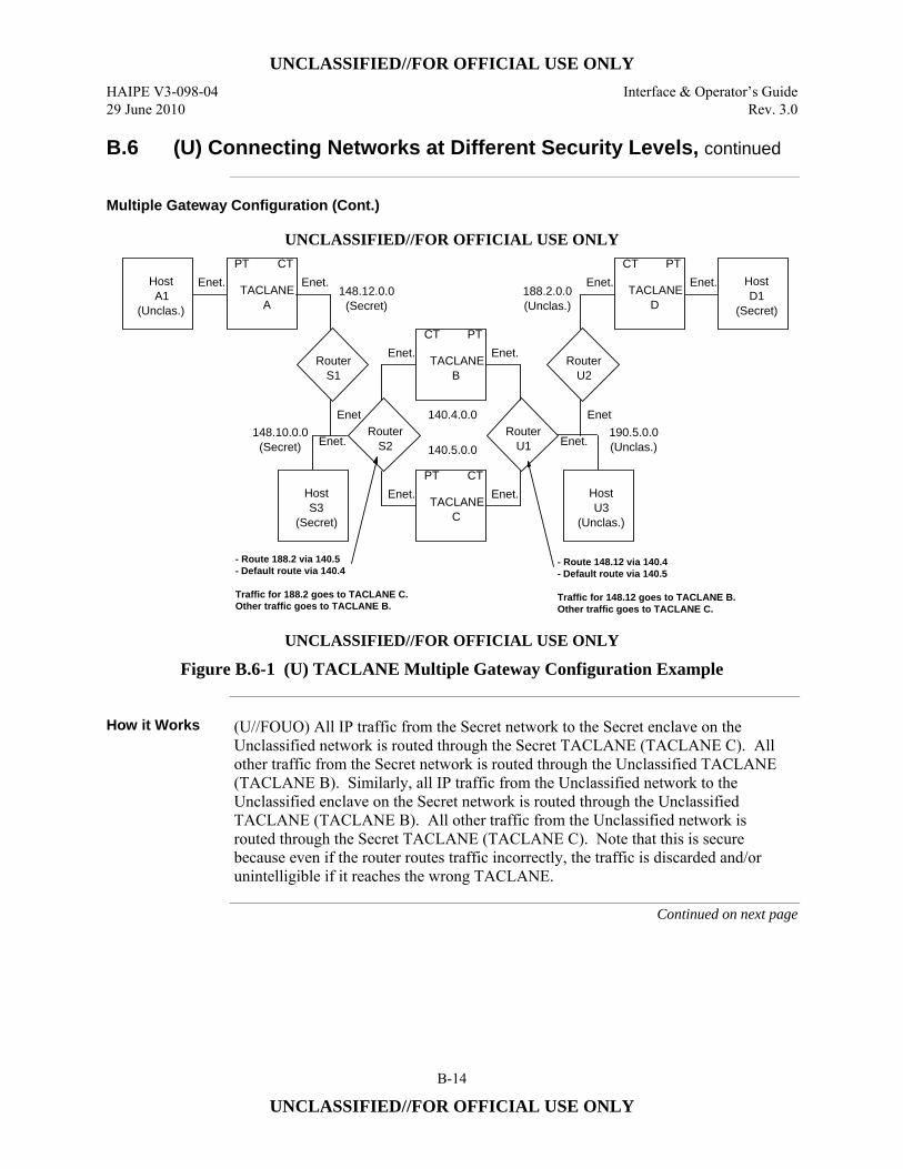
UNCLASSIFIED//FOR OFFICIAL USE ONLY
HAIPE V3-098-04 Interface & Operator’s Guide 29 June 2010 Rev. 3.0
B-14
UNCLASSIFIED//FOR OFFICIAL USE ONLY
B.6 (U) Connecting Networks at Different Security Levels, continued
Multiple Gateway Configuration (Cont.)
UNCLASSIFIED//FOR OFFICIAL USE ONLY
TACLANEB
CT PTEnet. Enet.
RouterS2 Enet.
RouterU1
TACLANEC
PT CTEnet. Enet.
RouterS1
Enet.
Enet
TACLANEA
PT CTEnet. Enet.Host
A1(Unclas.)
RouterU2
Enet
TACLANED
CT PTEnet.Enet.
HostU3
(Unclas.)
HostS3
(Secret)
HostD1
(Secret)
148.12.0.0(Secret)
188.2.0.0(Unclas.)
190.5.0.0(Unclas.)
148.10.0.0(Secret)
140.4.0.0
140.5.0.0
- Route 148.12 via 140.4- Default route via 140.5
Traffic for 148.12 goes to TACLANE B.Other traffic goes to TACLANE C.
- Route 188.2 via 140.5- Default route via 140.4
Traffic for 188.2 goes to TACLANE C. Other traffic goes to TACLANE B.
UNCLASSIFIED//FOR OFFICIAL USE ONLY
Figure B.6-1 (U) TACLANE Multiple Gateway Configuration Example
How it Works (U//FOUO) All IP traffic from the Secret network to the Secret enclave on the
Unclassified network is routed through the Secret TACLANE (TACLANE C). All other traffic from the Secret network is routed through the Unclassified TACLANE (TACLANE B). Similarly, all IP traffic from the Unclassified network to the Unclassified enclave on the Secret network is routed through the Unclassified TACLANE (TACLANE B). All other traffic from the Unclassified network is routed through the Secret TACLANE (TACLANE C). Note that this is secure because even if the router routes traffic incorrectly, the traffic is discarded and/or unintelligible if it reaches the wrong TACLANE.
Continued on next page
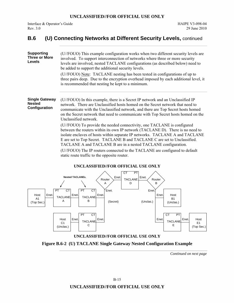
UNCLASSIFIED//FOR OFFICIAL USE ONLY
Interface & Operator’s Guide HAIPE V3-098-04 Rev. 3.0 29 June 2010
B-15
UNCLASSIFIED//FOR OFFICIAL USE ONLY
B.6 (U) Connecting Networks at Different Security Levels, continued
Supporting Three or More Levels
(U//FOUO) This example configuration works when two different security levels are involved. To support interconnection of networks where three or more security levels are involved, nested TACLANE configurations (as described below) need to be added to support the additional security levels. (U//FOUO) Note: TACLANE nesting has been tested in configurations of up to three pairs deep. Due to the encryption overhead imposed by each additional level, it is recommended that nesting be kept to a minimum.
Single Gateway Nested Configuration
(U//FOUO) In this example, there is a Secret IP network and an Unclassified IP network. There are Unclassified hosts homed on the Secret network that need to communicate with the Unclassified network, and there are Top Secret hosts homed on the Secret network that need to communicate with Top Secret hosts homed on the Unclassified network. (U//FOUO) To provide the needed connectivity, one TACLANE is configured between the routers within its own IP network (TACLANE D). There is no need to isolate enclaves of hosts within separate IP networks. TACLANE A and TACLANE E are set to Top Secret. TACLANE B and TACLANE C are set to Unclassified. TACLANE A and TACLANE B are in a nested TACLANE configuration. (U//FOUO) The IP routers connected to the TACLANE are configured to default static route traffic to the opposite router.
UNCLASSIFIED//FOR OFFICIAL USE ONLY
TACLANED
CT PTEnet.Enet.
RouterA
RouterB
Nested TACLANEs.
Enet. Enet.
TACLANEB
PT CTEnet. Enet.
TACLANEC
PT CTEnet. Enet.
TACLANEE
CT PTEnet. Enet.
Enet.HostA1
(Top Sec.)
HostC1
(Unclas.)
TACLANEA
PT CTEnet. Host
B1(Unclas.)
HostE1
(Top Sec.)
(Secret) (Unclas.)
UNCLASSIFIED//FOR OFFICIAL USE ONLY
Figure B.6-2 (U) TACLANE Single Gateway Nested Configuration Example
Continued on next page
UNCLASSIFIED//FOR OFFICIAL USE ONLY
HAIPE V3-098-04 Interface & Operator’s Guide 29 June 2010 Rev. 3.0
B-16
UNCLASSIFIED//FOR OFFICIAL USE ONLY
B.6 (U) Connecting Networks at Different Security Levels, continued
How it Works (U//FOUO) All IP traffic between the Unclassified network and the Unclassified
enclaves on the Secret network travels through a pair of Unclassified TACLANEs (TACLANE B and TACLANE D, or TACLANE C and TACLANE D). Host C1 communicates with Host B1 through TACLANE C and TACLANE D. Top Secret traffic between Host A1 and Host E1 is handled by the nested TACLANE configuration. TACLANE A and TACLANE E are peer Top Secret TACLANEs, and TACLANE B and TACLANE D are peer Unclassified TACLANEs. The nested TACLANE configuration overlays the protected Top Secret traffic over the Unclassified traffic in order for it to be able to use the same TACLANE-protected network. This is secure because of the TACLANE nesting. The Unclassified TACLANEs isolate Unclassified traffic from the Secret network, and the Top Secret TACLANEs isolate traffic from the Unclassified network.
B.7 (U) Multiple Gateways from Network
Introduction (U//FOUO) In this example, there is one backbone network and three TACLANE-
protected networks off of the backbone network. Each TACLANE-protected network is at the same security level. This configuration is illustrated in the figure below. (U//FOUO) Note: Remote TACLANE static routing ARP enhancements allow multiple PT or CT gateways to be supported with the only requirement that these multiple gateways support proxy-ARP. TACLANEs ARP for off-net destinations when the PT or CT default gateway is not defined.
Continued on next page
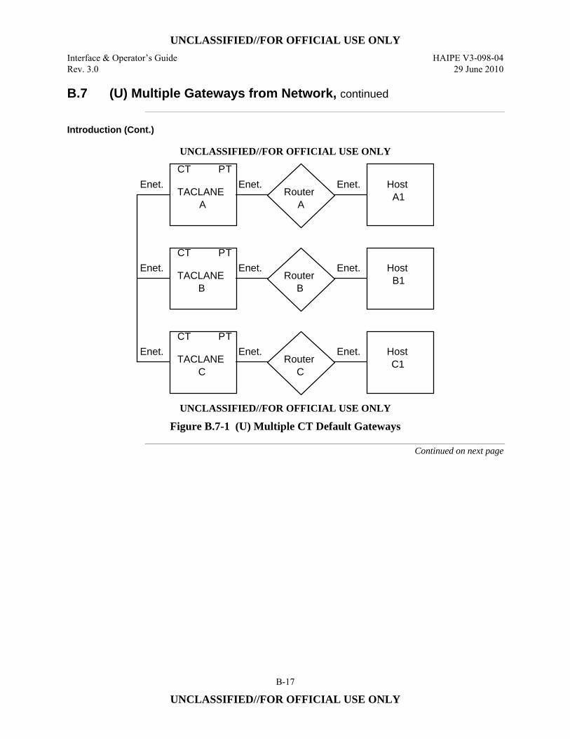
UNCLASSIFIED//FOR OFFICIAL USE ONLY
Interface & Operator’s Guide HAIPE V3-098-04 Rev. 3.0 29 June 2010
B-17
UNCLASSIFIED//FOR OFFICIAL USE ONLY
B.7 (U) Multiple Gateways from Network, continued
Introduction (Cont.)
UNCLASSIFIED//FOR OFFICIAL USE ONLY
TACLANEA
CT PTEnet. Enet.
TACLANEB
CT PTEnet. Enet.
TACLANEC
CT PTEnet. Enet.
RouterA
Enet. HostA1
RouterB
Enet. HostB1
RouterC
Enet. HostC1
UNCLASSIFIED//FOR OFFICIAL USE ONLY
Figure B.7-1 (U) Multiple CT Default Gateways
Continued on next page
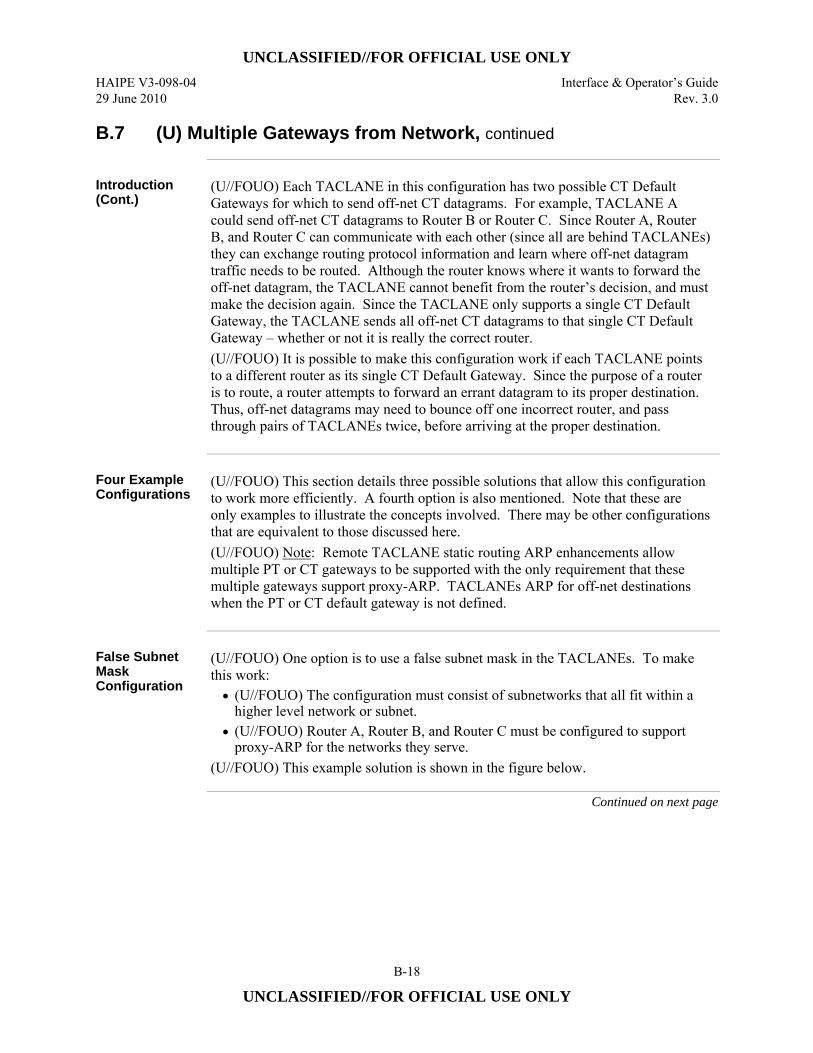
UNCLASSIFIED//FOR OFFICIAL USE ONLY
HAIPE V3-098-04 Interface & Operator’s Guide 29 June 2010 Rev. 3.0
B-18
UNCLASSIFIED//FOR OFFICIAL USE ONLY
B.7 (U) Multiple Gateways from Network, continued
Introduction (Cont.)
(U//FOUO) Each TACLANE in this configuration has two possible CT Default Gateways for which to send off-net CT datagrams. For example, TACLANE A could send off-net CT datagrams to Router B or Router C. Since Router A, Router B, and Router C can communicate with each other (since all are behind TACLANEs) they can exchange routing protocol information and learn where off-net datagram traffic needs to be routed. Although the router knows where it wants to forward the off-net datagram, the TACLANE cannot benefit from the router’s decision, and must make the decision again. Since the TACLANE only supports a single CT Default Gateway, the TACLANE sends all off-net CT datagrams to that single CT Default Gateway – whether or not it is really the correct router. (U//FOUO) It is possible to make this configuration work if each TACLANE points to a different router as its single CT Default Gateway. Since the purpose of a router is to route, a router attempts to forward an errant datagram to its proper destination. Thus, off-net datagrams may need to bounce off one incorrect router, and pass through pairs of TACLANEs twice, before arriving at the proper destination.
Four Example Configurations
(U//FOUO) This section details three possible solutions that allow this configuration to work more efficiently. A fourth option is also mentioned. Note that these are only examples to illustrate the concepts involved. There may be other configurations that are equivalent to those discussed here. (U//FOUO) Note: Remote TACLANE static routing ARP enhancements allow multiple PT or CT gateways to be supported with the only requirement that these multiple gateways support proxy-ARP. TACLANEs ARP for off-net destinations when the PT or CT default gateway is not defined.
False Subnet Mask Configuration
(U//FOUO) One option is to use a false subnet mask in the TACLANEs. To make this work: • (U//FOUO) The configuration must consist of subnetworks that all fit within a
higher level network or subnet. • (U//FOUO) Router A, Router B, and Router C must be configured to support
proxy-ARP for the networks they serve. (U//FOUO) This example solution is shown in the figure below.
Continued on next page
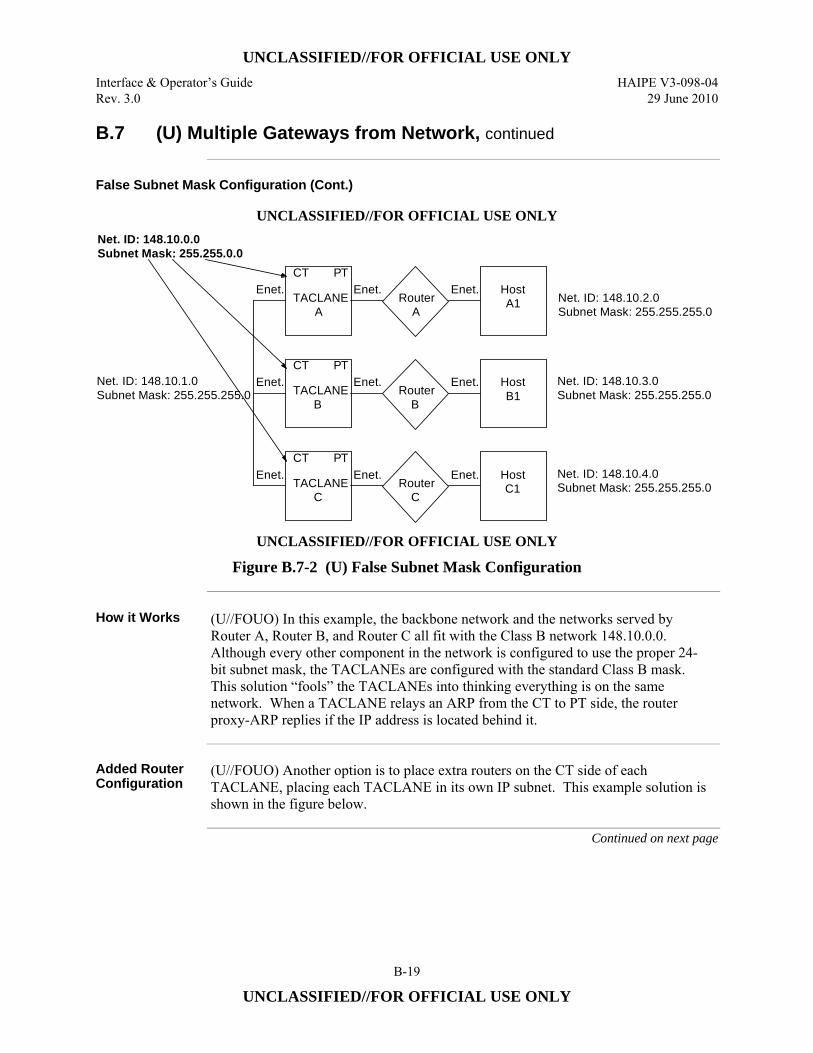
UNCLASSIFIED//FOR OFFICIAL USE ONLY
Interface & Operator’s Guide HAIPE V3-098-04 Rev. 3.0 29 June 2010
B-19
UNCLASSIFIED//FOR OFFICIAL USE ONLY
B.7 (U) Multiple Gateways from Network, continued
False Subnet Mask Configuration (Cont.)
UNCLASSIFIED//FOR OFFICIAL USE ONLY
TACLANEA
CT PTEnet. Enet.
TACLANEB
CT PTEnet. Enet.
TACLANEC
CT PTEnet. Enet.
RouterA
Enet. HostA1
RouterB
Enet. HostB1
RouterC
Enet. HostC1
Net. ID: 148.10.0.0 Subnet Mask: 255.255.0.0
Net. ID: 148.10.2.0Subnet Mask: 255.255.255.0
Net. ID: 148.10.3.0Subnet Mask: 255.255.255.0
Net. ID: 148.10.4.0Subnet Mask: 255.255.255.0
Net. ID: 148.10.1.0 Subnet Mask: 255.255.255.0
UNCLASSIFIED//FOR OFFICIAL USE ONLY
Figure B.7-2 (U) False Subnet Mask Configuration
How it Works (U//FOUO) In this example, the backbone network and the networks served by
Router A, Router B, and Router C all fit with the Class B network 148.10.0.0. Although every other component in the network is configured to use the proper 24-bit subnet mask, the TACLANEs are configured with the standard Class B mask. This solution “fools” the TACLANEs into thinking everything is on the same network. When a TACLANE relays an ARP from the CT to PT side, the router proxy-ARP replies if the IP address is located behind it.
Added Router Configuration
(U//FOUO) Another option is to place extra routers on the CT side of each TACLANE, placing each TACLANE in its own IP subnet. This example solution is shown in the figure below.
Continued on next page
UNCLASSIFIED//FOR OFFICIAL USE ONLY
HAIPE V3-098-04 Interface & Operator’s Guide 29 June 2010 Rev. 3.0
B-20
UNCLASSIFIED//FOR OFFICIAL USE ONLY
B.7 (U) Multiple Gateways from Network, continued
Added Router Configuration (Cont.)
UNCLASSIFIED//FOR OFFICIAL USE ONLY
TACLANEA
CT PTEnet.
TACLANEB
CT PTEnet.
TACLANEC
CT PTEnet.
RouterA
Enet. Host A1
RouterB
Enet. Host B1
RouterC
Enet. Host C1
Enet.
Enet.
Enet.
Router A2
Enet.
Router B2
Enet.
Router C2
Enet.
UNCLASSIFIED//FOR OFFICIAL USE ONLY
Figure B.7-3 (U) Added Router Configuration
How it Works (U//FOUO) This solution provides one destination IP address for which each
TACLANE can forward off-net CT datagrams. Each added router becomes a CT Default Gateway for each respective TACLANE. The added routers take care of routing datagrams to the proper destination.
Manual PPK Configuration
(U//FOUO) Another option is to manually configure each TACLANE with IP PPK assignments including each remote host IP address that is reachable behind every other TACLANE. This example solution is shown in the figure below.
Continued on next page
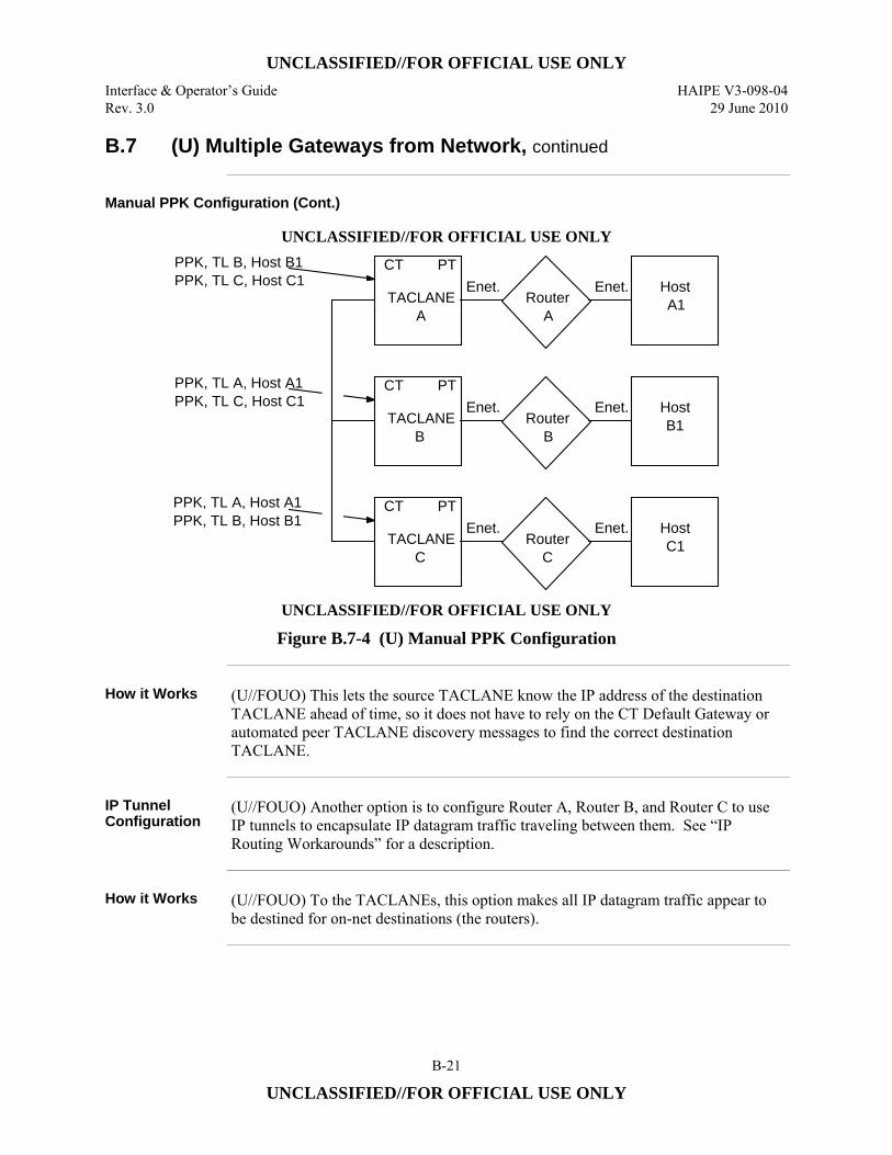
UNCLASSIFIED//FOR OFFICIAL USE ONLY
Interface & Operator’s Guide HAIPE V3-098-04 Rev. 3.0 29 June 2010
B-21
UNCLASSIFIED//FOR OFFICIAL USE ONLY
B.7 (U) Multiple Gateways from Network, continued
Manual PPK Configuration (Cont.)
UNCLASSIFIED//FOR OFFICIAL USE ONLY
TACLANEA
CT PTEnet.
TACLANEB
CT PTEnet.
TACLANEC
CT PTEnet.
RouterA
Enet. HostA1
RouterB
Enet. HostB1
RouterC
Enet. HostC1
PPK, TL B, Host B1PPK, TL C, Host C1
PPK, TL A, Host A1PPK, TL C, Host C1
PPK, TL A, Host A1PPK, TL B, Host B1
UNCLASSIFIED//FOR OFFICIAL USE ONLY
Figure B.7-4 (U) Manual PPK Configuration
How it Works (U//FOUO) This lets the source TACLANE know the IP address of the destination
TACLANE ahead of time, so it does not have to rely on the CT Default Gateway or automated peer TACLANE discovery messages to find the correct destination TACLANE.
IP Tunnel Configuration
(U//FOUO) Another option is to configure Router A, Router B, and Router C to use IP tunnels to encapsulate IP datagram traffic traveling between them. See “IP Routing Workarounds” for a description.
How it Works (U//FOUO) To the TACLANEs, this option makes all IP datagram traffic appear to
be destined for on-net destinations (the routers).
UNCLASSIFIED//FOR OFFICIAL USE ONLY
HAIPE V3-098-04 Interface & Operator’s Guide 29 June 2010 Rev. 3.0
B-22
UNCLASSIFIED//FOR OFFICIAL USE ONLY
B.8 (U) Redundancy Configurations
Introduction (U//FOUO) Several user communities require TACLANE redundancy. Usually the
requirement is for failover redundancy at a single high value TACLANE-protected enclave (e.g., WAN gateway or server farm), but redundancy can be implemented at any number of enclaves in a community. The case where the high value enclave is protected by two or more TACLANEs and client enclaves are each protected by a single TACLANE is referred to as single-ended redundancy. The case where every enclave is protected by two or more TACLANEs is referred to as double-ended redundancy. (U//FOUO) The level of TACLANE redundancy that is required at a TACLANE-protected enclave is typically two TACLANEs. Some user communities have a requirement to protect a high value enclave with as many as six TACLANEs. The configuration will also incorporate router redundancy if the redundancy requirement extends beyond TACLANE to the router on the Plaintext (PT) side. The redundancy requirement usually includes the capability to load balance between the redundant TACLANEs that protect an enclave when more than one TACLANE is operational. (U//FOUO) Currently, TACLANE does not have an internal redundancy function. The TL operator must rely on routing protocols to implement TACLANE redundancy. The examples in this section are limited to the configuration of Cisco Systems’ Generic Routing Encapsulation (GRE) tunnels and a routing protocol running on PT routers as a means to provide TACLANE redundancy. Other TACLANE redundancy configurations may be possible (e.g., using the Virtual Redundant Router Protocol (VRRP) or Cisco Systems’ Hot Standby Routing Protocol (HSRP)), but they have not yet been tested by General Dynamics. (U//FOUO) Note: Each of the redundancy configurations described in this section can be implemented with either Pre-Placed Key (PPK) or FIREFLY vector sets.
Single-Ended Redundancy
(U//FOUO) Two examples of single-ended redundancy configurations are presented here, each showing encrypted SIPRNET traffic tunneled through the NIPRNET. The first example provides router redundancy as well as TACLANE redundancy; the second example provides only TACLANE redundancy. FIREFLY or Pre-Placed Key Security Associations can be used between TACLANEs in either example. (U//FOUO) The TACLANE operator must choose how to configure the TLs. One option is to assign the CT and PT IP addresses to a single black (NIPRNET) subnet. In this case, the red (SIPRNET) and black (NIPRNET) address spaces are separated at the router on the PT side of each TACLANE. Another option is to assign each TL a black (NIPRNET) CT IP address and a red (SIPRNET) PT IP address and configure each TL with static routes.
Continued on next page
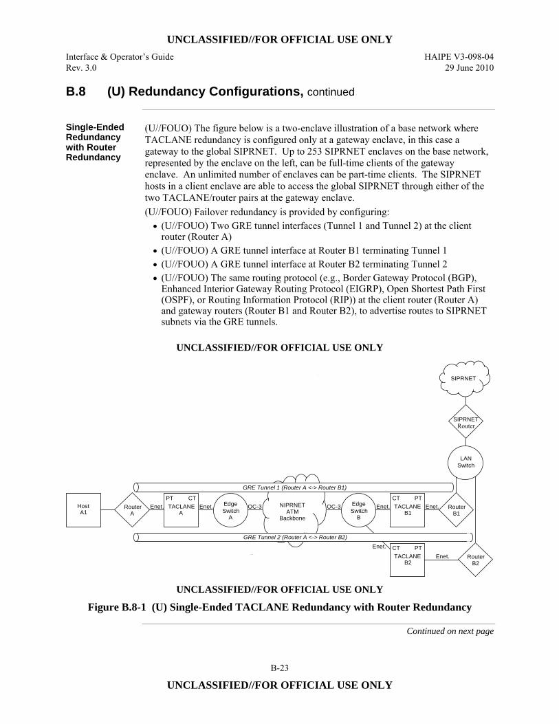
UNCLASSIFIED//FOR OFFICIAL USE ONLY
Interface & Operator’s Guide HAIPE V3-098-04 Rev. 3.0 29 June 2010
B-23
UNCLASSIFIED//FOR OFFICIAL USE ONLY
B.8 (U) Redundancy Configurations, continued
Single-Ended Redundancy with Router Redundancy
(U//FOUO) The figure below is a two-enclave illustration of a base network where TACLANE redundancy is configured only at a gateway enclave, in this case a gateway to the global SIPRNET. Up to 253 SIPRNET enclaves on the base network, represented by the enclave on the left, can be full-time clients of the gateway enclave. An unlimited number of enclaves can be part-time clients. The SIPRNET hosts in a client enclave are able to access the global SIPRNET through either of the two TACLANE/router pairs at the gateway enclave. (U//FOUO) Failover redundancy is provided by configuring: • (U//FOUO) Two GRE tunnel interfaces (Tunnel 1 and Tunnel 2) at the client
router (Router A) • (U//FOUO) A GRE tunnel interface at Router B1 terminating Tunnel 1 • (U//FOUO) A GRE tunnel interface at Router B2 terminating Tunnel 2 • (U//FOUO) The same routing protocol (e.g., Border Gateway Protocol (BGP),
Enhanced Interior Gateway Routing Protocol (EIGRP), Open Shortest Path First (OSPF), or Routing Information Protocol (RIP)) at the client router (Router A) and gateway routers (Router B1 and Router B2), to advertise routes to SIPRNET subnets via the GRE tunnels.
UNCLASSIFIED//FOR OFFICIAL USE ONLY
NIPRNET ATM
Backbone
Host A1
Router SwitchA
A
TACLANE A
Enet. Enet. OC-3 OC-3EdgeSwitch
B
Edge TACLANE B1
Enet. RouterEnet. B1
TACLANE B2
RouterEnet.B2
Enet.
Switch
PT PT
PT
CT CT
CT
SIPRNETRouter
SIPRNET
GRE Tunnel 1 (Router A <-> Router B1)
GRE Tunnel 2 (Router A <-> Router B2)
LAN
UNCLASSIFIED//FOR OFFICIAL USE ONLY
Figure B.8-1 (U) Single-Ended TACLANE Redundancy with Router Redundancy
Continued on next page
UNCLASSIFIED//FOR OFFICIAL USE ONLY
HAIPE V3-098-04 Interface & Operator’s Guide 29 June 2010 Rev. 3.0
B-24
UNCLASSIFIED//FOR OFFICIAL USE ONLY
B.8 (U) Redundancy Configurations, continued
How it Works (U//FOUO) Each GRE tunnel connects the client red router (Router A) and
TACLANE with a different red router and TACLANE at the gateway enclave. The routing protocol running on the red routers periodically sends keep-alives (or Hellos) through the GRE tunnels to the routers on the other end. A router will detect that a GRE tunnel is down when it ceases to receive routing protocol keep-alives from the router at the other end of the tunnel. The failure/unavailability of a gateway TACLANE disables one GRE tunnel and causes the client red router to route packets for the gateway enclave or off-base SIPRNET subnets through the other GRE tunnel (gateway TACLANE/router pair) until the disabled GRE tunnel is again available. The SIPRNET Router exchanges routing information with the gateway red routers and will route all packets for the client SIPRNET subnet to the gateway red router that continues to report a route (GRE tunnel path) to the subnet when the other gateway red router or its connected TACLANE fails or becomes unavailable. (U//FOUO) Note: The interval between keep-alives and the amount of time that the routing protocol will wait for a keep-alive before declaring a tunnel down can be set so that failover occurs in a few seconds.
Load-Balancing (U//FOUO) The client router (Router A) and the SIPRNET Router automatically
balance the load of packets they send to the two GRE tunnels (gateway TACLANE/router pairs), when the cost of the two GRE tunnels is equal and both tunnels are up. The routers will load-balance either on a per-packet basis or on a per-destination basis, depending on whether fast switching is enabled at the tunnel interfaces.
Note on Multicast Routing Protocol Packets
(U//FOUO) Depending on the routing protocol, the protocol can be configured with or without the GRE tunnel interface of the other red router as a protocol neighbor. The GRE tunnels will support the multicast routing protocol messages (e.g., “all OSPF routers”) that routers exchange when neighbors are not configured. A GRE tunnel interface will encapsulate a multicast routing protocol packet with a unicast IP header, addressed to the other tunnel end.
Single-Ended Redundancy without Router Redundancy
(U//FOUO) The figure below is another two-enclave example of a base network where TACLANE redundancy is configured only at a gateway enclave. The number of gateway red routers has been reduced to one, making this configuration applicable when the redundancy requirement does not extend beyond the TACLANE. Note that the failure/unavailability of the gateway red router (Router B) will disable both GRE tunnels and the use of both TACLANEs at the gateway.
Continued on next page
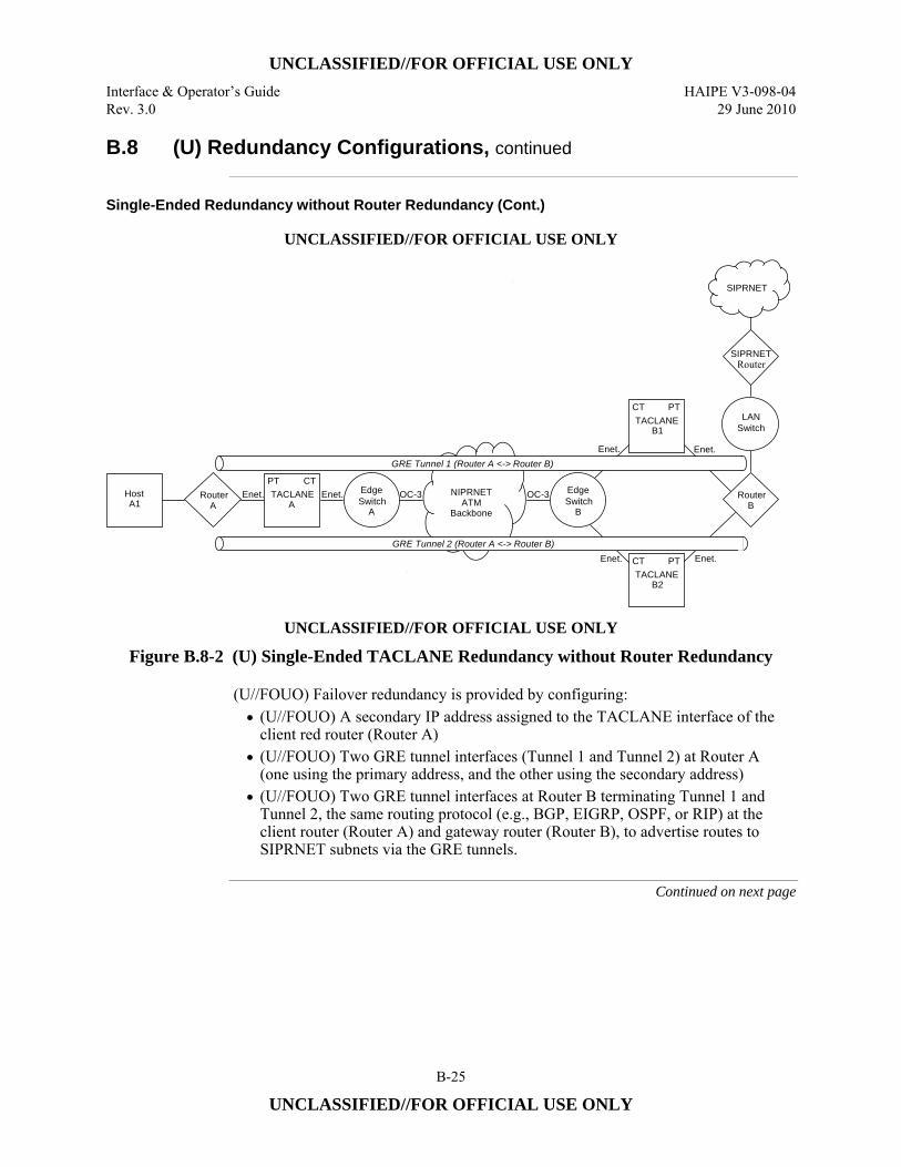
UNCLASSIFIED//FOR OFFICIAL USE ONLY
Interface & Operator’s Guide HAIPE V3-098-04 Rev. 3.0 29 June 2010
B-25
UNCLASSIFIED//FOR OFFICIAL USE ONLY
B.8 (U) Redundancy Configurations, continued
Single-Ended Redundancy without Router Redundancy (Cont.)
UNCLASSIFIED//FOR OFFICIAL USE ONLY
NIPRNET ATM
Backbone
Host A1
Router SwitchA
A
TACLANE A
Enet. Enet. OC-3 OC-3EdgeSwitch
B
Edge
TACLANE B1
Enet.
Router
Enet.
B
TACLANE B2
Enet. Enet.
Switch
PT
PT
PT
CT
CT
CT
SIPRNETRouter
SIPRNET
GRE Tunnel 1 (Router A <-> Router B)
GRE Tunnel 2 (Router A <-> Router B)
LAN
UNCLASSIFIED//FOR OFFICIAL USE ONLY
Figure B.8-2 (U) Single-Ended TACLANE Redundancy without Router Redundancy (U//FOUO) Failover redundancy is provided by configuring:
• (U//FOUO) A secondary IP address assigned to the TACLANE interface of the client red router (Router A)
• (U//FOUO) Two GRE tunnel interfaces (Tunnel 1 and Tunnel 2) at Router A (one using the primary address, and the other using the secondary address)
• (U//FOUO) Two GRE tunnel interfaces at Router B terminating Tunnel 1 and Tunnel 2, the same routing protocol (e.g., BGP, EIGRP, OSPF, or RIP) at the client router (Router A) and gateway router (Router B), to advertise routes to SIPRNET subnets via the GRE tunnels.
Continued on next page
UNCLASSIFIED//FOR OFFICIAL USE ONLY
HAIPE V3-098-04 Interface & Operator’s Guide 29 June 2010 Rev. 3.0
B-26
UNCLASSIFIED//FOR OFFICIAL USE ONLY
B.8 (U) Redundancy Configurations, continued
How it Works (U//FOUO) The secondary address at the client red router (Router A) allows the
gateway red router (Router B) to distinguish between the client ends of the two GRE tunnels, to forward packets for the client end of GRE Tunnel 1 to TACLANE B1, and to forward packets for the client end of GRE Tunnel 2 to TACLANE B2. A secondary IP address is not required for Router B, since it uses a separate physical interface (with a unique IP address) for each GRE tunnel (gateway TACLANE). (U//FOUO) The two PT interfaces of TACLANE B1 and TACLANE B2 could be connected to a single interface of Router B (through a hub or switch) by assigning a secondary address to the router interface, assigning TACLANE B1 to the primary subnet of the interface, and assigning TACLANE B2 to the secondary subnet of the interface. This causes the client TL (TACLANE A) to discover that TACLANE B1 fronts the gateway end of GRE Tunnel 1 and that TACLANE B2 fronts the gateway end of GRE tunnel 2. (U//FOUO) Failover redundancy functions in this example as it was described in the previous example, except that the gateway red router selects the GRE tunnel (gateway TACLANE) that carries a packet to the client SIPRNET subnet. Recall that it was the SIPRNET Router that selected the GRE tunnel in the first example, by forwarding the packet to one of the gateway red routers.
Double-Ended Redundancy
(U//FOUO) As the name implies, double-ended redundancy provides redundancy at both ends of a connection between two high value enclaves. Double-ended redundancy between two TACLANE-protected enclaves can be implemented by configuring either two or four GRE tunnels between the red routers of the enclaves. Only the four tunnel case is illustrated here, as the two tunnel case is a subset of the four tunnel case. (U//FOUO) Double-ended redundancy can be implemented by configuring all the TACLANEs for static routing or by configuring all the TACLANEs for same subnet operation using dynamic discovery. As with single-ended redundancy, either FIREFLY or Pre-Placed Key Security Associations can be used between the TACLANEs. Also, TACLANEs can be used in any combination.
Double-Ended Redundancy with Four GRE Tunnels
(U//FOUO) The figure below depicts a two-enclave network where failover redundancy is provided at both enclaves by configuring four GRE tunnels and a routing protocol between the red routers at the two enclaves. Remote TACLANE static routing is used in this example; the red (private) and black (SIPRNET) address spaces are separated at each TACLANE. Subnets beginning with “p1.p2” are private, and subnets beginning with “s1.s2” are SIPRNET subnets.
Continued on next page
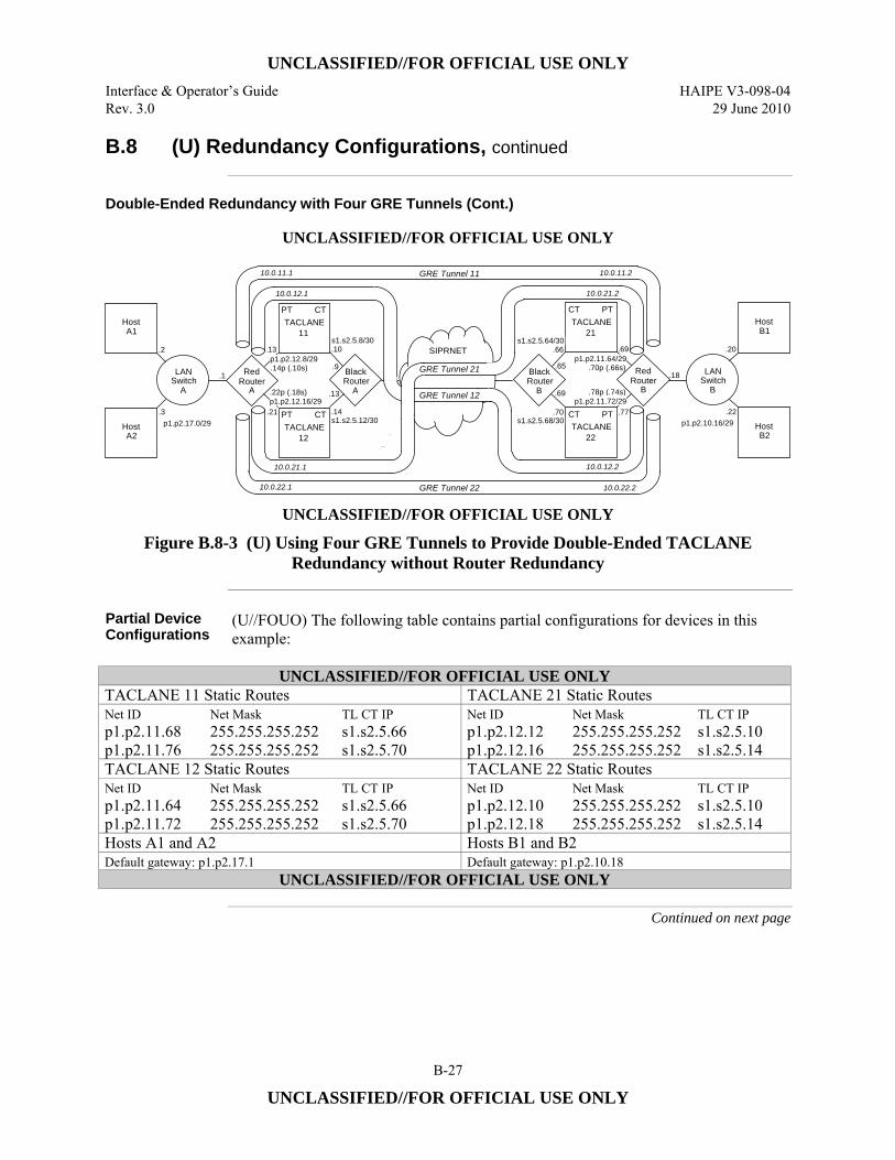
UNCLASSIFIED//FOR OFFICIAL USE ONLY
Interface & Operator’s Guide HAIPE V3-098-04 Rev. 3.0 29 June 2010
B-27
UNCLASSIFIED//FOR OFFICIAL USE ONLY
B.8 (U) Redundancy Configurations, continued
Double-Ended Redundancy with Four GRE Tunnels (Cont.)
UNCLASSIFIED//FOR OFFICIAL USE ONLY
SIPRNET
Host A1
RouterA
TACLANE 11
PT CT
GRE Tunnel 12
Host A2
Switch A
LAN Black
TACLANE 12
PT CT
Router A
Red
p1.p2.17.0/29
.1
.2
.3
p1.p2.12.8/29
p1.p2.12.16/29
s1.s2.5.8/30
s1.s2.5.12/30
.10
.9
.13
.14
.14p (.10s)
.22p (.18s)
.13
.21
HostB1
RouterB
TACLANE21
CT PT
HostB2
SwitchB
LANBlack
TACLANE22
CT PT
Router B
Red
p1.p2.10.16/29.22
s1.s2.5.64/30
s1.s2.5.68/30
.66
.65
.69
.70
.20
.18
p1.p2.11.64/29
p1.p2.11.72/29
.70p (.66s)
.78p (.74s)
.69
.77
GRE Tunnel 22
GRE Tunnel 21
GRE Tunnel 11
10.0.22.1
10.0.11.1
10.0.12.1
10.0.21.1
10.0.11.2
10.0.21.2
10.0.12.2
10.0.22.2 UNCLASSIFIED//FOR OFFICIAL USE ONLY
Figure B.8-3 (U) Using Four GRE Tunnels to Provide Double-Ended TACLANE Redundancy without Router Redundancy
Partial Device Configurations
(U//FOUO) The following table contains partial configurations for devices in this example:
UNCLASSIFIED//FOR OFFICIAL USE ONLY
TACLANE 11 Static Routes TACLANE 21 Static Routes Net ID p1.p2.11.68 p1.p2.11.76
Net Mask 255.255.255.252 255.255.255.252
TL CT IP s1.s2.5.66 s1.s2.5.70
Net ID p1.p2.12.12 p1.p2.12.16
Net Mask 255.255.255.252 255.255.255.252
TL CT IP s1.s2.5.10 s1.s2.5.14
TACLANE 12 Static Routes TACLANE 22 Static Routes Net ID p1.p2.11.64 p1.p2.11.72
Net Mask 255.255.255.252 255.255.255.252
TL CT IP s1.s2.5.66 s1.s2.5.70
Net ID p1.p2.12.10 p1.p2.12.18
Net Mask 255.255.255.252 255.255.255.252
TL CT IP s1.s2.5.10 s1.s2.5.14
Hosts A1 and A2 Hosts B1 and B2 Default gateway: p1.p2.17.1 Default gateway: p1.p2.10.18
UNCLASSIFIED//FOR OFFICIAL USE ONLY
Continued on next page
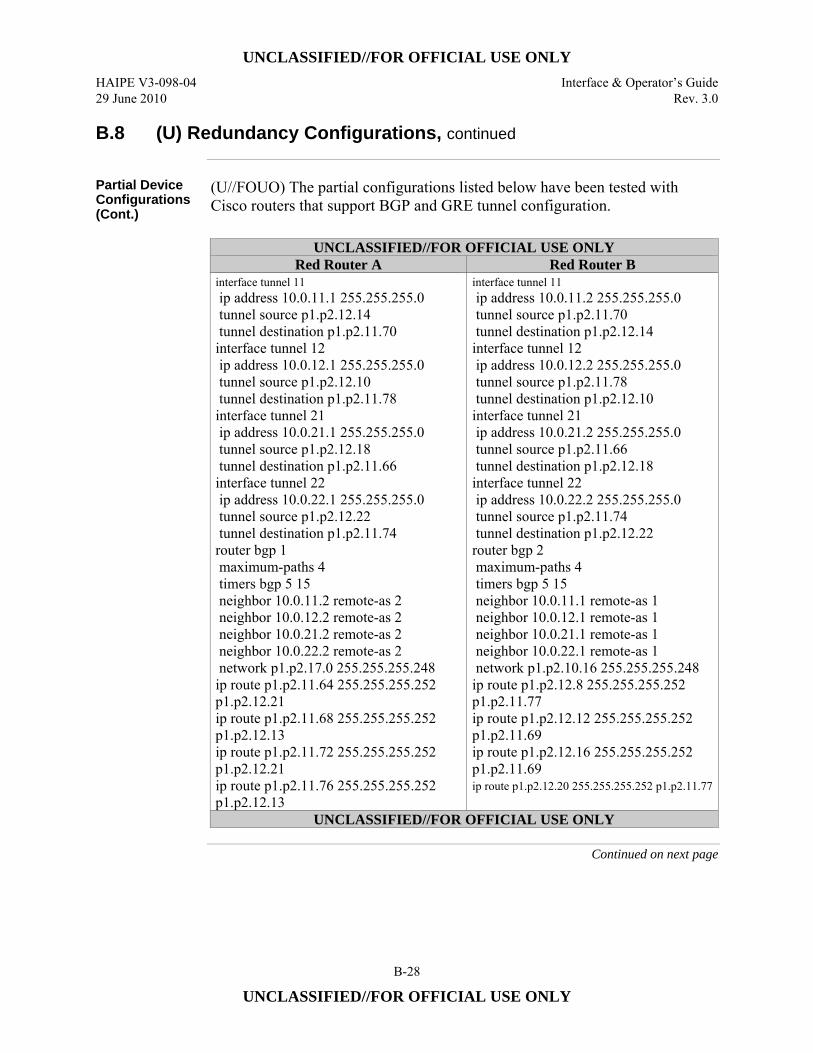
UNCLASSIFIED//FOR OFFICIAL USE ONLY
HAIPE V3-098-04 Interface & Operator’s Guide 29 June 2010 Rev. 3.0
B-28
UNCLASSIFIED//FOR OFFICIAL USE ONLY
B.8 (U) Redundancy Configurations, continued
Partial Device Configurations (Cont.)
(U//FOUO) The partial configurations listed below have been tested with Cisco routers that support BGP and GRE tunnel configuration.
UNCLASSIFIED//FOR OFFICIAL USE ONLY
Red Router A Red Router B interface tunnel 11 ip address 10.0.11.1 255.255.255.0 tunnel source p1.p2.12.14 tunnel destination p1.p2.11.70 interface tunnel 12 ip address 10.0.12.1 255.255.255.0 tunnel source p1.p2.12.10 tunnel destination p1.p2.11.78 interface tunnel 21 ip address 10.0.21.1 255.255.255.0 tunnel source p1.p2.12.18 tunnel destination p1.p2.11.66 interface tunnel 22 ip address 10.0.22.1 255.255.255.0 tunnel source p1.p2.12.22 tunnel destination p1.p2.11.74 router bgp 1 maximum-paths 4 timers bgp 5 15 neighbor 10.0.11.2 remote-as 2 neighbor 10.0.12.2 remote-as 2 neighbor 10.0.21.2 remote-as 2 neighbor 10.0.22.2 remote-as 2 network p1.p2.17.0 255.255.255.248 ip route p1.p2.11.64 255.255.255.252 p1.p2.12.21 ip route p1.p2.11.68 255.255.255.252 p1.p2.12.13 ip route p1.p2.11.72 255.255.255.252 p1.p2.12.21 ip route p1.p2.11.76 255.255.255.252 p1.p2.12.13
interface tunnel 11 ip address 10.0.11.2 255.255.255.0 tunnel source p1.p2.11.70 tunnel destination p1.p2.12.14 interface tunnel 12 ip address 10.0.12.2 255.255.255.0 tunnel source p1.p2.11.78 tunnel destination p1.p2.12.10 interface tunnel 21 ip address 10.0.21.2 255.255.255.0 tunnel source p1.p2.11.66 tunnel destination p1.p2.12.18 interface tunnel 22 ip address 10.0.22.2 255.255.255.0 tunnel source p1.p2.11.74 tunnel destination p1.p2.12.22 router bgp 2 maximum-paths 4 timers bgp 5 15 neighbor 10.0.11.1 remote-as 1 neighbor 10.0.12.1 remote-as 1 neighbor 10.0.21.1 remote-as 1 neighbor 10.0.22.1 remote-as 1 network p1.p2.10.16 255.255.255.248 ip route p1.p2.12.8 255.255.255.252 p1.p2.11.77 ip route p1.p2.12.12 255.255.255.252 p1.p2.11.69 ip route p1.p2.12.16 255.255.255.252 p1.p2.11.69 ip route p1.p2.12.20 255.255.255.252 p1.p2.11.77
UNCLASSIFIED//FOR OFFICIAL USE ONLY
Continued on next page
UNCLASSIFIED//FOR OFFICIAL USE ONLY
Interface & Operator’s Guide HAIPE V3-098-04 Rev. 3.0 29 June 2010
B-29
UNCLASSIFIED//FOR OFFICIAL USE ONLY
B.8 (U) Redundancy Configurations, continued
How it Works (U//FOUO) A unique IP address is provided for each GRE tunnel endpoint by
assigning both a primary and a secondary address to each TACLANE-connected red router interface. The unique tunnel endpoint addresses allow a red router to route the packets for the destination ends of two tunnels to one connected TACLANE and to route the packets for the destination ends of the other two tunnels to the second connected TACLANE. The unique addresses also allow a TACLANE to route encrypted packets to different TACLANEs at the other enclave depending on the destination (tunnel endpoint) address. Accordingly, four static routes are configured at each red router and two static routes are configured at each TACLANE. The result is that the path of each GRE tunnel passes through a different combination of TACLANEs, one from each enclave. (U//FOUO) The same routing protocol (BGP-4 in this example) is enabled at each red router and configured to advertise the private host subnet of its enclave via each of the four GRE tunnels. The red routers will detect that a GRE tunnel is down when they cease to receive routing protocol keep-alives from the red router at the other enclave through the tunnel. The failure/unavailability of a TACLANE at one enclave will disable two GRE tunnel paths and cause each red router to route all the packets for the private host subnet of the other enclave through the two remaining GRE tunnels. The overlapping failure/unavailability of a TACLANE at the opposite enclave will disable a third GRE tunnel path and cause each red router to route all the packets for the private host subnet of the other enclave through the one remaining GRE tunnel. The BGP-4 router configurations shown will failover in 15 seconds. (U//FOUO) In the figure, the PT interface of each TACLANE connects to a different interface of the red router at each enclave. The PT interfaces of the two TACLANEs could connect to a single red router interface at an enclave if a total of four IP addresses (one primary plus three secondary) were assigned to the router interface. This would reduce the number of static routes required at the other red router from four to two.
Continued on next page
UNCLASSIFIED//FOR OFFICIAL USE ONLY
HAIPE V3-098-04 Interface & Operator’s Guide 29 June 2010 Rev. 3.0
B-30
UNCLASSIFIED//FOR OFFICIAL USE ONLY
B.8 (U) Redundancy Configurations, continued
Analysis (U//FOUO) The four GRE tunnel configuration is more robust that a two GRE tunnel
configuration. With only two tunnels, the probability is 0.5 that the overlapping failure/unavailability of one TACLANE at each enclave will disable communications between the private subnets of the two enclaves. This can be seen by visualizing that only GRE Tunnel 11 and GRE Tunnel 22 are configured. The failure of TACLANE 21 will disable GRE Tunnel 11 and remove TACLANE 11 from service. The overlapping failure of TACLANE 12 will then disable GRE Tunnel 22 so that no path remains between the two red routers. In the four tunnel configuration, the failure of TACLANE 21 does not disable GRE Tunnel 12 or remove TACLANE 11 from service, so an overlapping failure of TACLANE 12 still leaves the path through GRE Tunnel 12 intact. (U//FOUO) A four tunnel configuration may be more robust than is necessary in a network where the number of TACLANE-protected enclaves is very large. The probability that one TL will fail at each enclave at the same time decreases as the number of enclaves increases. If the redundancy design must assure that all n enclaves remain connected when one TL is unavailable at each of the n enclaves, then a four tunnel configuration is needed. If all n enclaves must remain connected when one TL is unavailable at each of n-1 (or fewer) enclaves, then a two tunnel configuration may be sufficient, but enclave-to-enclave latency could increase. If enclave-to-enclave latency must not increase when one TL fails at two or more enclaves, then a four tunnel configuration will be necessary. The number of GRE tunnels can be reduced by half in some networks where the redundancy and latency requirements and the number of enclaves allow failover to a partial mesh of enclave tunnels, where some enclave pairs can only be connected through the red router of a third enclave.
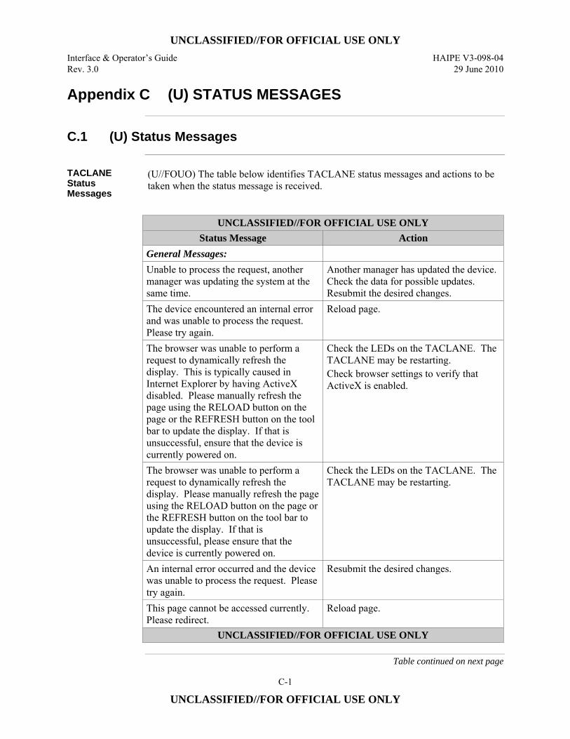
UNCLASSIFIED//FOR OFFICIAL USE ONLY
Interface & Operator’s Guide HAIPE V3-098-04 Rev. 3.0 29 June 2010
C-1
UNCLASSIFIED//FOR OFFICIAL USE ONLY
Appendix C (U) STATUS MESSAGES
C.1 (U) Status Messages
TACLANE Status Messages
(U//FOUO) The table below identifies TACLANE status messages and actions to be taken when the status message is received.
UNCLASSIFIED//FOR OFFICIAL USE ONLY
Status Message Action General Messages: Unable to process the request, another manager was updating the system at the same time.
Another manager has updated the device. Check the data for possible updates. Resubmit the desired changes.
The device encountered an internal error and was unable to process the request. Please try again.
Reload page.
The browser was unable to perform a request to dynamically refresh the display. This is typically caused in Internet Explorer by having ActiveX disabled. Please manually refresh the page using the RELOAD button on the page or the REFRESH button on the tool bar to update the display. If that is unsuccessful, ensure that the device is currently powered on.
Check the LEDs on the TACLANE. The TACLANE may be restarting. Check browser settings to verify that ActiveX is enabled.
The browser was unable to perform a request to dynamically refresh the display. Please manually refresh the page using the RELOAD button on the page or the REFRESH button on the tool bar to update the display. If that is unsuccessful, please ensure that the device is currently powered on.
Check the LEDs on the TACLANE. The TACLANE may be restarting.
An internal error occurred and the device was unable to process the request. Please try again.
Resubmit the desired changes.
This page cannot be accessed currently. Please redirect.
Reload page.
UNCLASSIFIED//FOR OFFICIAL USE ONLY
Table continued on next page
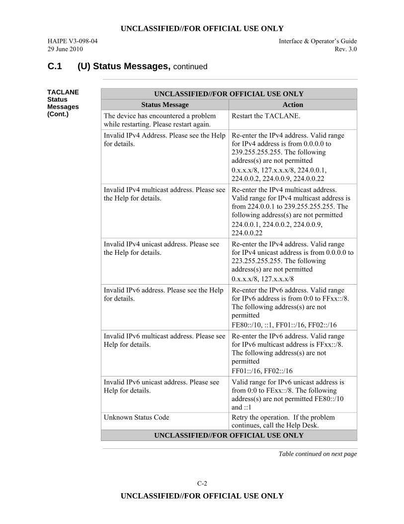
UNCLASSIFIED//FOR OFFICIAL USE ONLY
HAIPE V3-098-04 Interface & Operator’s Guide 29 June 2010 Rev. 3.0
C-2
UNCLASSIFIED//FOR OFFICIAL USE ONLY
C.1 (U) Status Messages, continued
TACLANE Status Messages (Cont.)
UNCLASSIFIED//FOR OFFICIAL USE ONLY Status Message Action
The device has encountered a problem while restarting. Please restart again.
Restart the TACLANE.
Invalid IPv4 Address. Please see the Help for details.
Re-enter the IPv4 address. Valid range for IPv4 address is from 0.0.0.0 to 239.255.255.255. The following address(s) are not permitted 0.x.x.x/8, 127.x.x.x/8, 224.0.0.1, 224.0.0.2, 224.0.0.9, 224.0.0.22
Invalid IPv4 multicast address. Please see the Help for details.
Re-enter the IPv4 multicast address. Valid range for IPv4 multicast address is from 224.0.0.1 to 239.255.255.255. The following address(s) are not permitted 224.0.0.1, 224.0.0.2, 224.0.0.9, 224.0.0.22
Invalid IPv4 unicast address. Please see the Help for details.
Re-enter the IPv4 address. Valid range for IPv4 unicast address is from 0.0.0.0 to 223.255.255.255. The following address(s) are not permitted 0.x.x.x/8, 127.x.x.x/8
Invalid IPv6 address. Please see the Help for details.
Re-enter the IPv6 address. Valid range for IPv6 address is from 0:0 to FFxx::/8. The following address(s) are not permitted FE80::/10, ::1, FF01::/16, FF02::/16
Invalid IPv6 multicast address. Please see Help for details.
Re-enter the IPv6 address. Valid range for IPv6 multicast address is FFxx::/8. The following address(s) are not permitted FF01::/16, FF02::/16
Invalid IPv6 unicast address. Please see Help for details.
Valid range for IPv6 unicast address is from 0:0 to FExx::/8. The following address(s) are not permitted FE80::/10 and ::1
Unknown Status Code Retry the operation. If the problem continues, call the Help Desk.
UNCLASSIFIED//FOR OFFICIAL USE ONLY
Table continued on next page
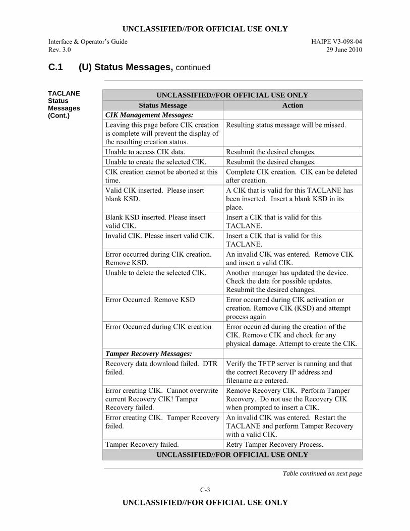
UNCLASSIFIED//FOR OFFICIAL USE ONLY
Interface & Operator’s Guide HAIPE V3-098-04 Rev. 3.0 29 June 2010
C-3
UNCLASSIFIED//FOR OFFICIAL USE ONLY
C.1 (U) Status Messages, continued
TACLANE Status Messages (Cont.)
UNCLASSIFIED//FOR OFFICIAL USE ONLY Status Message Action
CIK Management Messages: Leaving this page before CIK creation is complete will prevent the display of the resulting creation status.
Resulting status message will be missed.
Unable to access CIK data. Resubmit the desired changes. Unable to create the selected CIK. Resubmit the desired changes. CIK creation cannot be aborted at this time.
Complete CIK creation. CIK can be deleted after creation.
Valid CIK inserted. Please insert blank KSD.
A CIK that is valid for this TACLANE has been inserted. Insert a blank KSD in its place.
Blank KSD inserted. Please insert valid CIK.
Insert a CIK that is valid for this TACLANE.
Invalid CIK. Please insert valid CIK. Insert a CIK that is valid for this TACLANE.
Error occurred during CIK creation. Remove KSD.
An invalid CIK was entered. Remove CIK and insert a valid CIK.
Unable to delete the selected CIK. Another manager has updated the device. Check the data for possible updates. Resubmit the desired changes.
Error Occurred. Remove KSD Error occurred during CIK activation or creation. Remove CIK (KSD) and attempt process again
Error Occurred during CIK creation Error occurred during the creation of the CIK. Remove CIK and check for any physical damage. Attempt to create the CIK.
Tamper Recovery Messages: Recovery data download failed. DTR failed.
Verify the TFTP server is running and that the correct Recovery IP address and filename are entered.
Error creating CIK. Cannot overwrite current Recovery CIK! Tamper Recovery failed.
Remove Recovery CIK. Perform Tamper Recovery. Do not use the Recovery CIK when prompted to insert a CIK.
Error creating CIK. Tamper Recovery failed.
An invalid CIK was entered. Restart the TACLANE and perform Tamper Recovery with a valid CIK.
Tamper Recovery failed. Retry Tamper Recovery Process. UNCLASSIFIED//FOR OFFICIAL USE ONLY
Table continued on next page
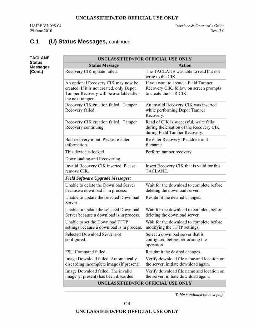
UNCLASSIFIED//FOR OFFICIAL USE ONLY
HAIPE V3-098-04 Interface & Operator’s Guide 29 June 2010 Rev. 3.0
C-4
UNCLASSIFIED//FOR OFFICIAL USE ONLY
C.1 (U) Status Messages, continued
TACLANE Status Messages (Cont.)
UNCLASSIFIED//FOR OFFICIAL USE ONLY Status Message Action
Recovery CIK update failed. The TACLANE was able to read but not write to the CIK.
An optional Recovery CIK may now be created. If it is not created, only Depot Tamper Recovery will be available after the next tamper
If you want to create a Field Tamper Recovery CIK, follow on screen prompts to create the FTR CIK.
Recovery CIK creation failed. Tamper Recovery failed.
An invalid Recovery CIK was inserted while performing Depot Tamper Recovery.
Recovery CIK creation failed. Tamper Recovery continuing.
Read of CIK is successful, write fails during the creation of the Recovery CIK during Field Tamper Recovery.
Bad recovery input. Please re-enter information.
Re-enter Recovery IP address and filename.
This device is locked. Perform tamper recovery. Downloading and Recovering. Invalid Recovery CIK inserted. Please remove CIK.
Insert Recovery CIK that is valid for this TACLANE.
Field Software Upgrade Messages: Unable to delete the Download Server because a download is in process.
Wait for the download to complete before deleting the download server.
Unable to update the selected Download Server.
Resubmit the desired changes.
Unable to update the selected Download Server because a download is in process.
Wait for the download to complete before deleting the download server.
Unable to set the Download TFTP settings because a download is in process.
Wait for the download to complete before modifying the TFTP settings.
Selected Download Server not configured.
Select a download server that is configured before performing the operation.
FSU Command failed. Resubmit the desired changes. Image Download failed. Automatically discarding incomplete image (if present).
Verify download file name and location on the server, initiate download again.
Image Download failed. The invalid image (if present) has been discarded
Verify download file name and location on the server, initiate download again.
UNCLASSIFIED//FOR OFFICIAL USE ONLY
Table continued on next page
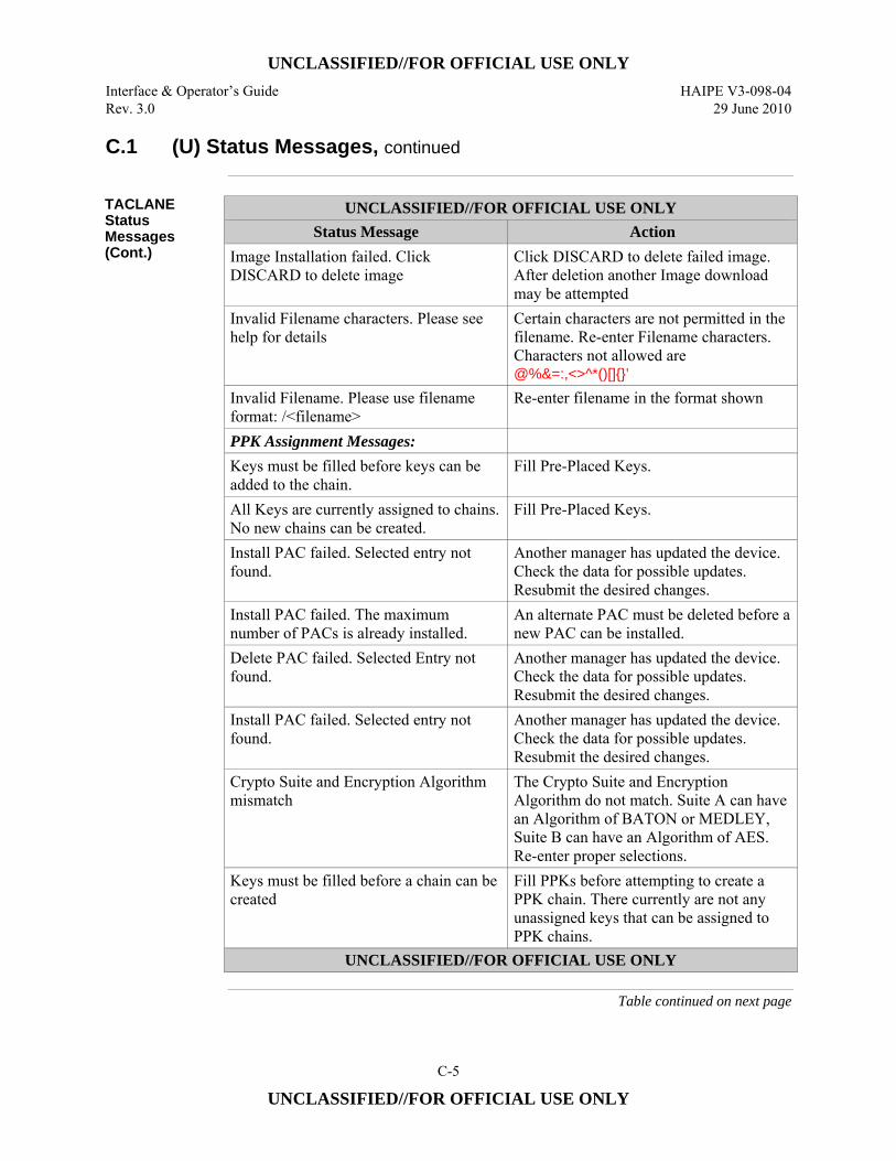
UNCLASSIFIED//FOR OFFICIAL USE ONLY
Interface & Operator’s Guide HAIPE V3-098-04 Rev. 3.0 29 June 2010
C-5
UNCLASSIFIED//FOR OFFICIAL USE ONLY
C.1 (U) Status Messages, continued
TACLANE Status Messages (Cont.)
UNCLASSIFIED//FOR OFFICIAL USE ONLY Status Message Action
Image Installation failed. Click DISCARD to delete image
Click DISCARD to delete failed image. After deletion another Image download may be attempted
Invalid Filename characters. Please see help for details
Certain characters are not permitted in the filename. Re-enter Filename characters. Characters not allowed are @%&=:,<>^*()[]{}’
Invalid Filename. Please use filename format: /<filename>
Re-enter filename in the format shown
PPK Assignment Messages: Keys must be filled before keys can be added to the chain.
Fill Pre-Placed Keys.
All Keys are currently assigned to chains. No new chains can be created.
Fill Pre-Placed Keys.
Install PAC failed. Selected entry not found.
Another manager has updated the device. Check the data for possible updates. Resubmit the desired changes.
Install PAC failed. The maximum number of PACs is already installed.
An alternate PAC must be deleted before a new PAC can be installed.
Delete PAC failed. Selected Entry not found.
Another manager has updated the device. Check the data for possible updates. Resubmit the desired changes.
Install PAC failed. Selected entry not found.
Another manager has updated the device. Check the data for possible updates. Resubmit the desired changes.
Crypto Suite and Encryption Algorithm mismatch
The Crypto Suite and Encryption Algorithm do not match. Suite A can have an Algorithm of BATON or MEDLEY, Suite B can have an Algorithm of AES. Re-enter proper selections.
Keys must be filled before a chain can be created
Fill PPKs before attempting to create a PPK chain. There currently are not any unassigned keys that can be assigned to PPK chains.
UNCLASSIFIED//FOR OFFICIAL USE ONLY
Table continued on next page
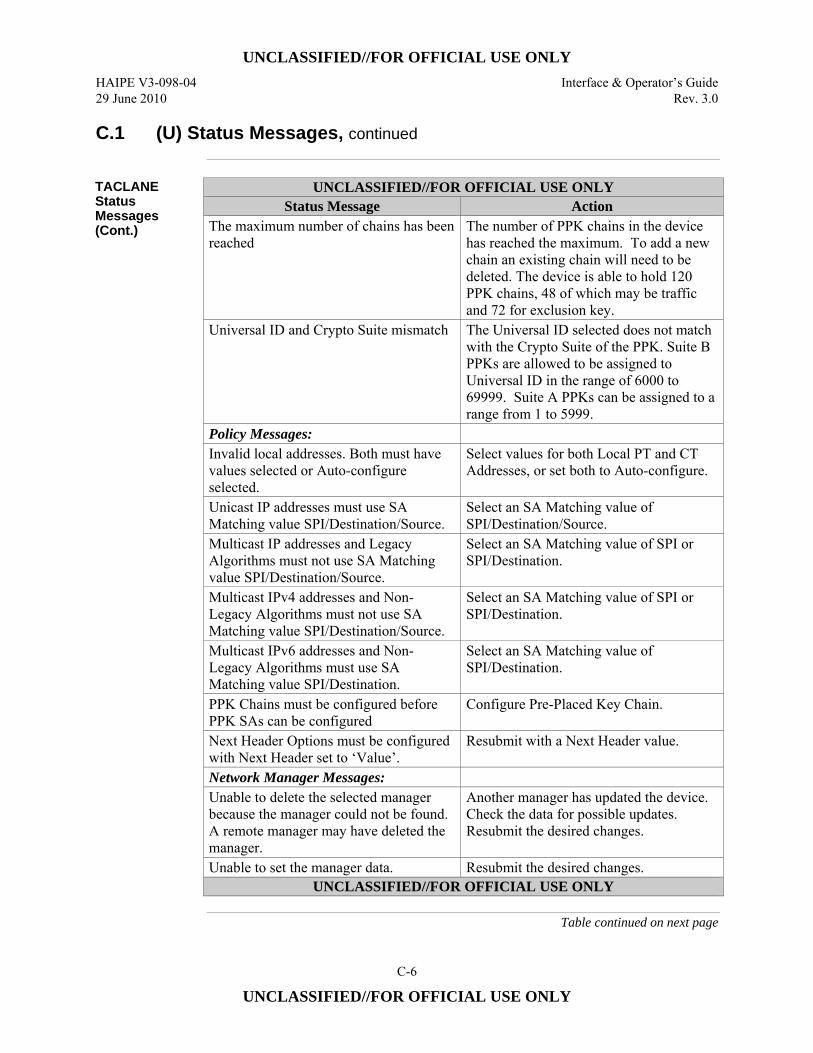
UNCLASSIFIED//FOR OFFICIAL USE ONLY
HAIPE V3-098-04 Interface & Operator’s Guide 29 June 2010 Rev. 3.0
C-6
UNCLASSIFIED//FOR OFFICIAL USE ONLY
C.1 (U) Status Messages, continued
TACLANE Status Messages (Cont.)
UNCLASSIFIED//FOR OFFICIAL USE ONLY Status Message Action
The maximum number of chains has been reached
The number of PPK chains in the device has reached the maximum. To add a new chain an existing chain will need to be deleted. The device is able to hold 120 PPK chains, 48 of which may be traffic and 72 for exclusion key.
Universal ID and Crypto Suite mismatch The Universal ID selected does not match with the Crypto Suite of the PPK. Suite B PPKs are allowed to be assigned to Universal ID in the range of 6000 to 69999. Suite A PPKs can be assigned to a range from 1 to 5999.
Policy Messages: Invalid local addresses. Both must have values selected or Auto-configure selected.
Select values for both Local PT and CT Addresses, or set both to Auto-configure.
Unicast IP addresses must use SA Matching value SPI/Destination/Source.
Select an SA Matching value of SPI/Destination/Source.
Multicast IP addresses and Legacy Algorithms must not use SA Matching value SPI/Destination/Source.
Select an SA Matching value of SPI or SPI/Destination.
Multicast IPv4 addresses and Non-Legacy Algorithms must not use SA Matching value SPI/Destination/Source.
Select an SA Matching value of SPI or SPI/Destination.
Multicast IPv6 addresses and Non-Legacy Algorithms must use SA Matching value SPI/Destination.
Select an SA Matching value of SPI/Destination.
PPK Chains must be configured before PPK SAs can be configured
Configure Pre-Placed Key Chain.
Next Header Options must be configured with Next Header set to ‘Value’.
Resubmit with a Next Header value.
Network Manager Messages: Unable to delete the selected manager because the manager could not be found. A remote manager may have deleted the manager.
Another manager has updated the device. Check the data for possible updates. Resubmit the desired changes.
Unable to set the manager data. Resubmit the desired changes. UNCLASSIFIED//FOR OFFICIAL USE ONLY
Table continued on next page
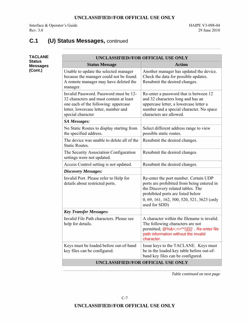
UNCLASSIFIED//FOR OFFICIAL USE ONLY
Interface & Operator’s Guide HAIPE V3-098-04 Rev. 3.0 29 June 2010
C-7
UNCLASSIFIED//FOR OFFICIAL USE ONLY
C.1 (U) Status Messages, continued
TACLANE Status Messages (Cont.)
UNCLASSIFIED//FOR OFFICIAL USE ONLY Status Message Action
Unable to update the selected manager because the manager could not be found. A remote manager may have deleted the manager.
Another manager has updated the device. Check the data for possible updates. Resubmit the desired changes.
Invalid Password. Password must be 12-32 characters and must contain at least one each of the following: uppercase letter, lowercase letter, number and special character
Re-enter a password that is between 12 and 32 characters long and has an uppercase letter, a lowercase letter a number and a special character. No space characters are allowed.
SA Messages: No Static Routes to display starting from the specified address.
Select different address range to view possible static routes.
The device was unable to delete all of the Static Routes.
Resubmit the desired changes.
The Security Association Configuration settings were not updated.
Resubmit the desired changes.
Access Control setting is not updated. Resubmit the desired changes. Discovery Messages: Invalid Port. Please refer to Help for details about restricted ports.
Re-enter the port number. Certain UDP ports are prohibited from being entered in the Discovery related tables. The prohibited ports are listed below 0, 69, 161, 162, 500, 520, 521, 3623 (only used for SDD)
Key Transfer Messages: Invalid File Path characters. Please see help for details.
A character within the filename is invalid. The following characters are not permitted; @%&=,<>^*()[]{}’ . Re-enter file path information without the invalid character.
Keys must be loaded before out-of-band key files can be configured.
Issue keys to the TACLANE. Keys must be in the loaded key table before out-of-band key files can be configured.
UNCLASSIFIED//FOR OFFICIAL USE ONLY
Table continued on next page
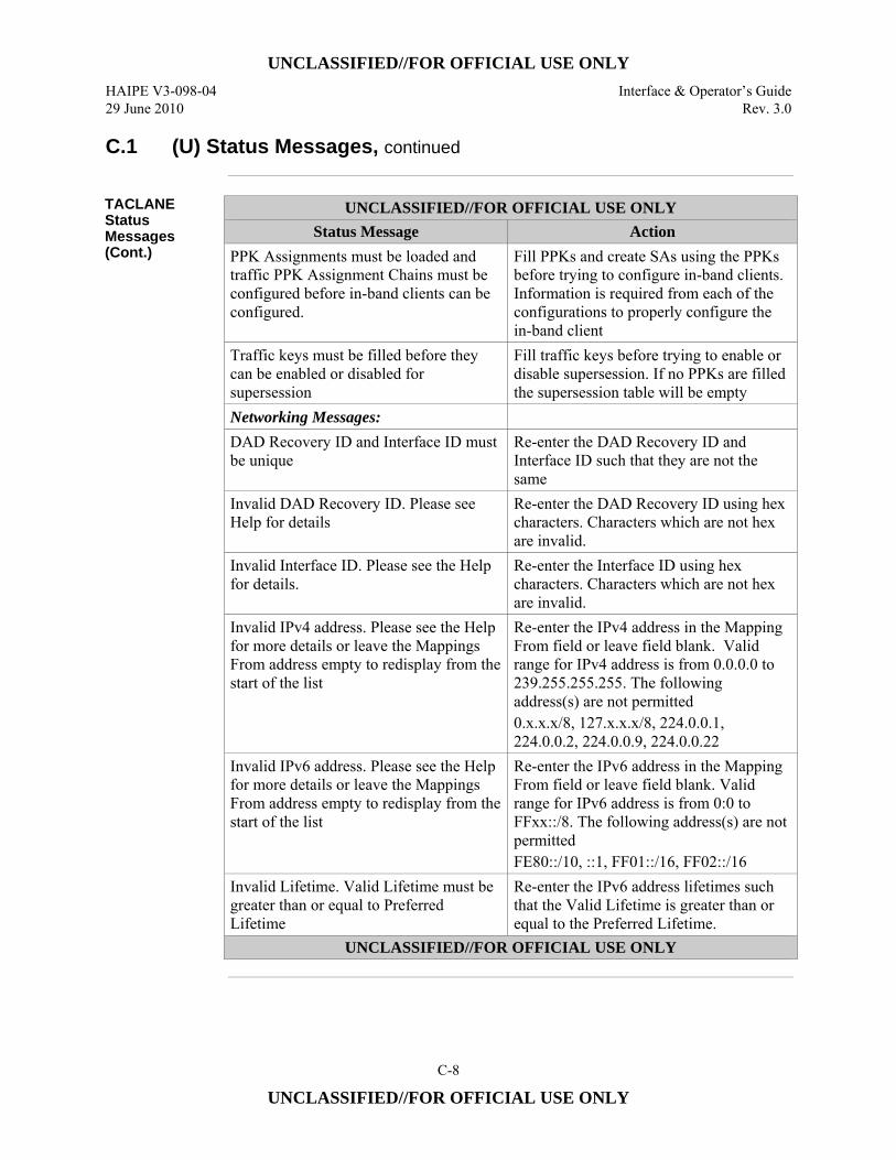
UNCLASSIFIED//FOR OFFICIAL USE ONLY
HAIPE V3-098-04 Interface & Operator’s Guide 29 June 2010 Rev. 3.0
C-8
UNCLASSIFIED//FOR OFFICIAL USE ONLY
C.1 (U) Status Messages, continued
TACLANE Status Messages (Cont.)
UNCLASSIFIED//FOR OFFICIAL USE ONLY Status Message Action
PPK Assignments must be loaded and traffic PPK Assignment Chains must be configured before in-band clients can be configured.
Fill PPKs and create SAs using the PPKs before trying to configure in-band clients. Information is required from each of the configurations to properly configure the in-band client
Traffic keys must be filled before they can be enabled or disabled for supersession
Fill traffic keys before trying to enable or disable supersession. If no PPKs are filled the supersession table will be empty
Networking Messages: DAD Recovery ID and Interface ID must be unique
Re-enter the DAD Recovery ID and Interface ID such that they are not the same
Invalid DAD Recovery ID. Please see Help for details
Re-enter the DAD Recovery ID using hex characters. Characters which are not hex are invalid.
Invalid Interface ID. Please see the Help for details.
Re-enter the Interface ID using hex characters. Characters which are not hex are invalid.
Invalid IPv4 address. Please see the Help for more details or leave the Mappings From address empty to redisplay from the start of the list
Re-enter the IPv4 address in the Mapping From field or leave field blank. Valid range for IPv4 address is from 0.0.0.0 to 239.255.255.255. The following address(s) are not permitted 0.x.x.x/8, 127.x.x.x/8, 224.0.0.1, 224.0.0.2, 224.0.0.9, 224.0.0.22
Invalid IPv6 address. Please see the Help for more details or leave the Mappings From address empty to redisplay from the start of the list
Re-enter the IPv6 address in the Mapping From field or leave field blank. Valid range for IPv6 address is from 0:0 to FFxx::/8. The following address(s) are not permitted FE80::/10, ::1, FF01::/16, FF02::/16
Invalid Lifetime. Valid Lifetime must be greater than or equal to Preferred Lifetime
Re-enter the IPv6 address lifetimes such that the Valid Lifetime is greater than or equal to the Preferred Lifetime.
UNCLASSIFIED//FOR OFFICIAL USE ONLY
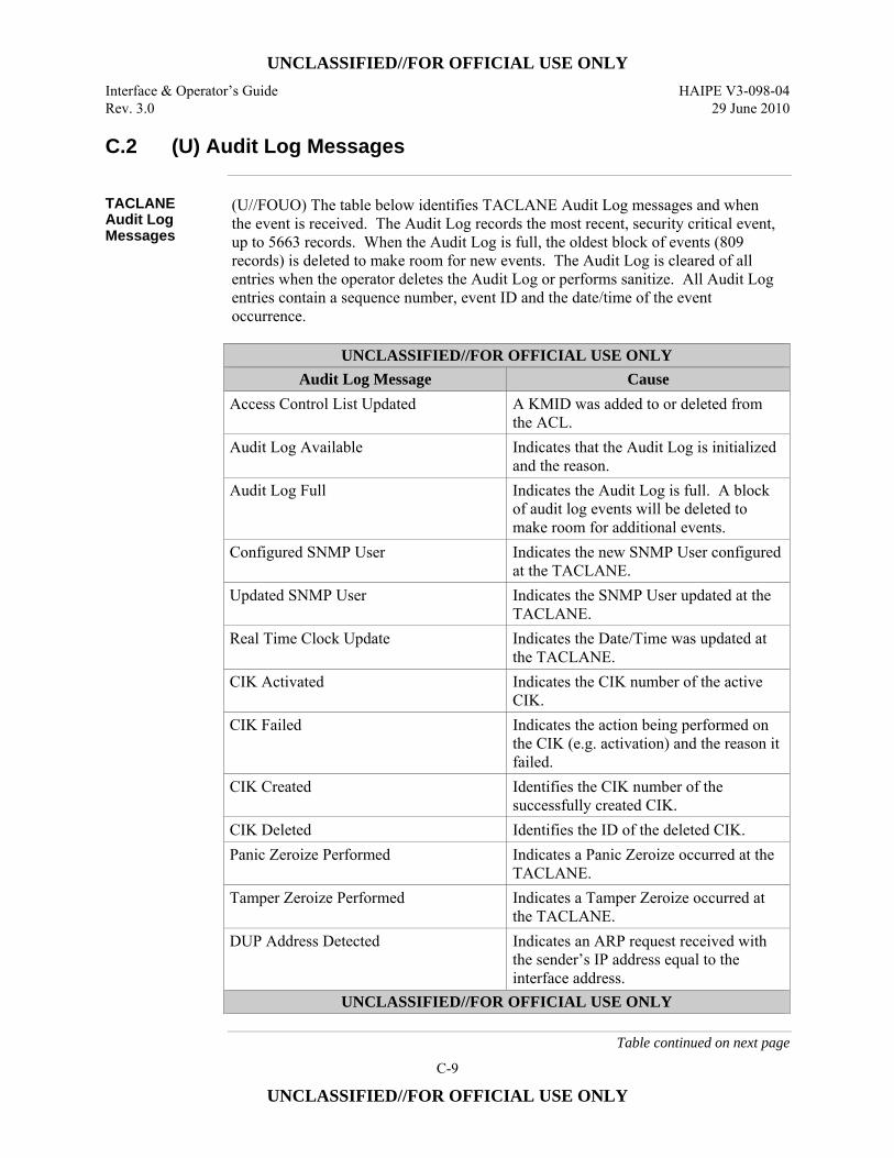
UNCLASSIFIED//FOR OFFICIAL USE ONLY
Interface & Operator’s Guide HAIPE V3-098-04 Rev. 3.0 29 June 2010
C-9
UNCLASSIFIED//FOR OFFICIAL USE ONLY
C.2 (U) Audit Log Messages
TACLANE Audit Log Messages
(U//FOUO) The table below identifies TACLANE Audit Log messages and when the event is received. The Audit Log records the most recent, security critical event, up to 5663 records. When the Audit Log is full, the oldest block of events (809 records) is deleted to make room for new events. The Audit Log is cleared of all entries when the operator deletes the Audit Log or performs sanitize. All Audit Log entries contain a sequence number, event ID and the date/time of the event occurrence.
UNCLASSIFIED//FOR OFFICIAL USE ONLY
Audit Log Message Cause Access Control List Updated A KMID was added to or deleted from
the ACL. Audit Log Available Indicates that the Audit Log is initialized
and the reason. Audit Log Full Indicates the Audit Log is full. A block
of audit log events will be deleted to make room for additional events.
Configured SNMP User Indicates the new SNMP User configured at the TACLANE.
Updated SNMP User Indicates the SNMP User updated at the TACLANE.
Real Time Clock Update Indicates the Date/Time was updated at the TACLANE.
CIK Activated Indicates the CIK number of the active CIK.
CIK Failed Indicates the action being performed on the CIK (e.g. activation) and the reason it failed.
CIK Created Identifies the CIK number of the successfully created CIK.
CIK Deleted Identifies the ID of the deleted CIK. Panic Zeroize Performed Indicates a Panic Zeroize occurred at the
TACLANE. Tamper Zeroize Performed Indicates a Tamper Zeroize occurred at
the TACLANE. DUP Address Detected Indicates an ARP request received with
the sender’s IP address equal to the interface address.
UNCLASSIFIED//FOR OFFICIAL USE ONLY
Table continued on next page
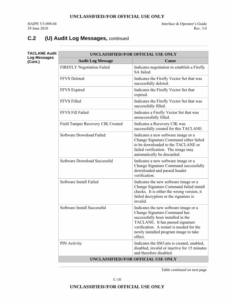
UNCLASSIFIED//FOR OFFICIAL USE ONLY
HAIPE V3-098-04 Interface & Operator’s Guide 29 June 2010 Rev. 3.0
C-10
UNCLASSIFIED//FOR OFFICIAL USE ONLY
C.2 (U) Audit Log Messages, continued
TACLANE Audit Log Messages (Cont.)
UNCLASSIFIED//FOR OFFICIAL USE ONLY Audit Log Message Cause
FIREFLY Negotiation Failed Indicates negotiation to establish a Firefly SA failed.
FFVS Deleted Indicates the Firefly Vector Set that was successfully deleted.
FFVS Expired Indicates the Firefly Vector Set that expired.
FFVS Filled Indicates the Firefly Vector Set that was successfully filled.
FFVS Fill Failed Indicates a Firefly Vector Set that was unsuccessfully filled.
Field Tamper Recovery CIK Created Indicates a Recovery CIK was successfully created for this TACLANE.
Software Download Failed Indicates a new software image or a Change Signature Command either failed to be downloaded to the TACLANE or failed verification. The image may automatically be discarded.
Software Download Successful Indicates a new software image or a Change Signature Command successfully downloaded and passed header verification.
Software Install Failed Indicates the new software image or a Change Signature Command failed install checks. It is either the wrong version, it failed decryption or the signature is invalid.
Software Install Successful Indicates the new software image or a Change Signature Command has successfully been installed in the TACLANE. It has passed signature verification. A restart is needed for the newly installed program image to take effect.
PIN Activity Indicates the SSO pin is created, enabled, disabled, invalid or inactive for 15 minutes and therefore disabled.
UNCLASSIFIED//FOR OFFICIAL USE ONLY
Table continued on next page

UNCLASSIFIED//FOR OFFICIAL USE ONLY
Interface & Operator’s Guide HAIPE V3-098-04 Rev. 3.0 29 June 2010
C-11
UNCLASSIFIED//FOR OFFICIAL USE ONLY
C.2 (U) Audit Log Messages, continued
TACLANE Audit Log Messages (Cont.)
UNCLASSIFIED//FOR OFFICIAL USE ONLY Audit Log Message Cause
PPK Deleted Indicates a Pre-Placed Key was successfully deleted from the TACLANE.
PPK Expired Indicates the Pre-Placed Key whose effective date has expired.
PPK Filled Indicates a Pre-Placed Key was successfully filled in the TACLANE.
PPK FILL Failed Indicates a Pre-Placed Key was filled in the TACLANE but did not pass checks.
PPK Traffic Use Indicates a Pre-Placed Key has been successfully configured as a Traffic key.
PPK EK Use Indicates a Pre-Placed Key has been successfully configured as an Exclusion key.
Privileged Configuration Modified Indicates the updated configuration item and the item’s old and new values.
System Time Updated Indicates the Date/Time was updated at the TACLANE.
HW Security Critical Fault Indicates a Hardware Error was detected at the TACLANE.
SW Security Critical Fault Indicates a Software Error was detected at the TACLANE.
SNMP Auth Error Indicates the SNMP manager failed authentication.
Diagnostic Failed Indicates a diagnostic test failed. KEK Updated Indicates Key Encryption Key successfully
updated. Configuration Reset Indicates the configuration successfully reset
and the type of data reset. FFVS SPD Activated FF Template was successfully created. FFVS SPD Destroyed FF Template was successfully deleted. FFVS TEK Created Indicates a Firefly TEK was successfully
created. FFVS TEK Deleted Indicates a Firefly TEK was successfully
deleted. PPK SAD In Activated PPK SA (Incoming) entry was successfully
created. UNCLASSIFIED//FOR OFFICIAL USE ONLY
Table continued on next page
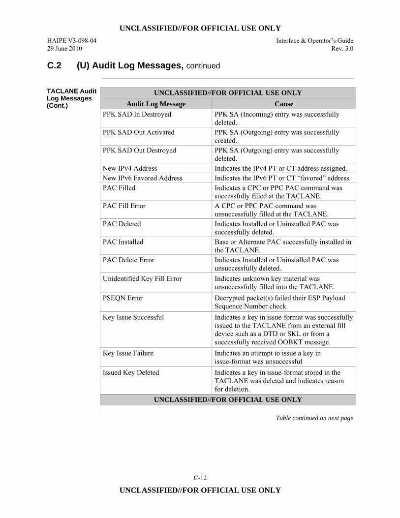
UNCLASSIFIED//FOR OFFICIAL USE ONLY
HAIPE V3-098-04 Interface & Operator’s Guide 29 June 2010 Rev. 3.0
C-12
UNCLASSIFIED//FOR OFFICIAL USE ONLY
C.2 (U) Audit Log Messages, continued
TACLANE Audit Log Messages (Cont.)
UNCLASSIFIED//FOR OFFICIAL USE ONLY Audit Log Message Cause
PPK SAD In Destroyed PPK SA (Incoming) entry was successfully deleted.
PPK SAD Out Activated PPK SA (Outgoing) entry was successfully created.
PPK SAD Out Destroyed PPK SA (Outgoing) entry was successfully deleted.
New IPv4 Address Indicates the IPv4 PT or CT address assigned. New IPv6 Favored Address Indicates the IPv6 PT or CT “favored” address. PAC Filled Indicates a CPC or PPC PAC command was
successfully filled at the TACLANE. PAC Fill Error A CPC or PPC PAC command was
unsuccessfully filled at the TACLANE. PAC Deleted Indicates Installed or Uninstalled PAC was
successfully deleted. PAC Installed Base or Alternate PAC successfully installed in
the TACLANE. PAC Delete Error Indicates Installed or Uninstalled PAC was
unsuccessfully deleted. Unidentified Key Fill Error Indicates unknown key material was
unsuccessfully filled into the TACLANE. PSEQN Error Decrypted packet(s) failed their ESP Payload
Sequence Number check. Key Issue Successful Indicates a key in issue-format was successfully
issued to the TACLANE from an external fill device such as a DTD or SKL or from a successfully received OOBKT message.
Key Issue Failure Indicates an attempt to issue a key in issue-format was unsuccessful
Issued Key Deleted Indicates a key in issue-format stored in the TACLANE was deleted and indicates reason for deletion.
UNCLASSIFIED//FOR OFFICIAL USE ONLY
Table continued on next page
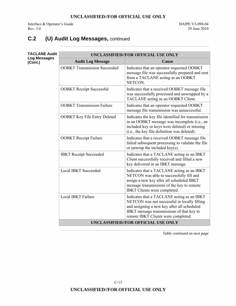
UNCLASSIFIED//FOR OFFICIAL USE ONLY
Interface & Operator’s Guide HAIPE V3-098-04 Rev. 3.0 29 June 2010
C-13
UNCLASSIFIED//FOR OFFICIAL USE ONLY
C.2 (U) Audit Log Messages, continued
TACLANE Audit Log Messages (Cont.)
UNCLASSIFIED//FOR OFFICIAL USE ONLY Audit Log Message Cause
OOBKT Transmission Succeeded Indicates that an operator requested OOBKT message file was successfully prepared and sent from a TACLANE acting as an OOBKT NETCON.
OOBKT Receipt Successful Indicates that a received OOBKT message file was successfully processed and unwrapped by a TACLANE acting as an OOBKT Client.
OOBKT Transmission Failure Indicates that an operator requested OOBKT message file transmission was unsuccessful.
OOBKT Key File Entry Deleted Indicates the key file identified for transmission in an OOBKT message was incomplete (i.e., an included key or keys were deleted) or missing (i.e., the key file definition was deleted).
OOBKT Receipt Failure Indicates that a received OOBKT message file failed subsequent processing to validate the file or unwrap the included key(s).
IBKT Receipt Succeeded Indicates that a TACLANE acting as an IBKT Client successfully received and filled a new key delivered in an IBKT message.
Local IBKT Succeeded Indicates that a TACLANE acting as an IBKT NETCON was able to successfully fill and assign a new key after all scheduled IBKT message transmissions of the key to remote IBKT Clients were completed.
Local IBKT Failure Indicates that a TACLANE acting as an IBKT NETCON was not successful in locally filling and assigning a new key after all scheduled IBKT message transmissions of that key to remote IBKT Clients were completed.
UNCLASSIFIED//FOR OFFICIAL USE ONLY
Table continued on next page
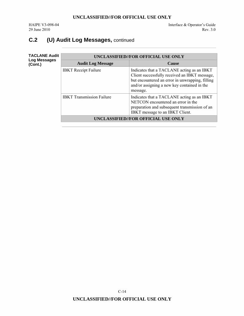
UNCLASSIFIED//FOR OFFICIAL USE ONLY
HAIPE V3-098-04 Interface & Operator’s Guide 29 June 2010 Rev. 3.0
C-14
UNCLASSIFIED//FOR OFFICIAL USE ONLY
C.2 (U) Audit Log Messages, continued
TACLANE Audit Log Messages (Cont.)
UNCLASSIFIED//FOR OFFICIAL USE ONLY Audit Log Message Cause
IBKT Receipt Failure Indicates that a TACLANE acting as an IBKT Client successfully received an IBKT message, but encountered an error in unwrapping, filling and/or assigning a new key contained in the message.
IBKT Transmission Failure Indicates that a TACLANE acting as an IBKT NETCON encountered an error in the preparation and subsequent transmission of an IBKT message to an IBKT Client.
UNCLASSIFIED//FOR OFFICIAL USE ONLY
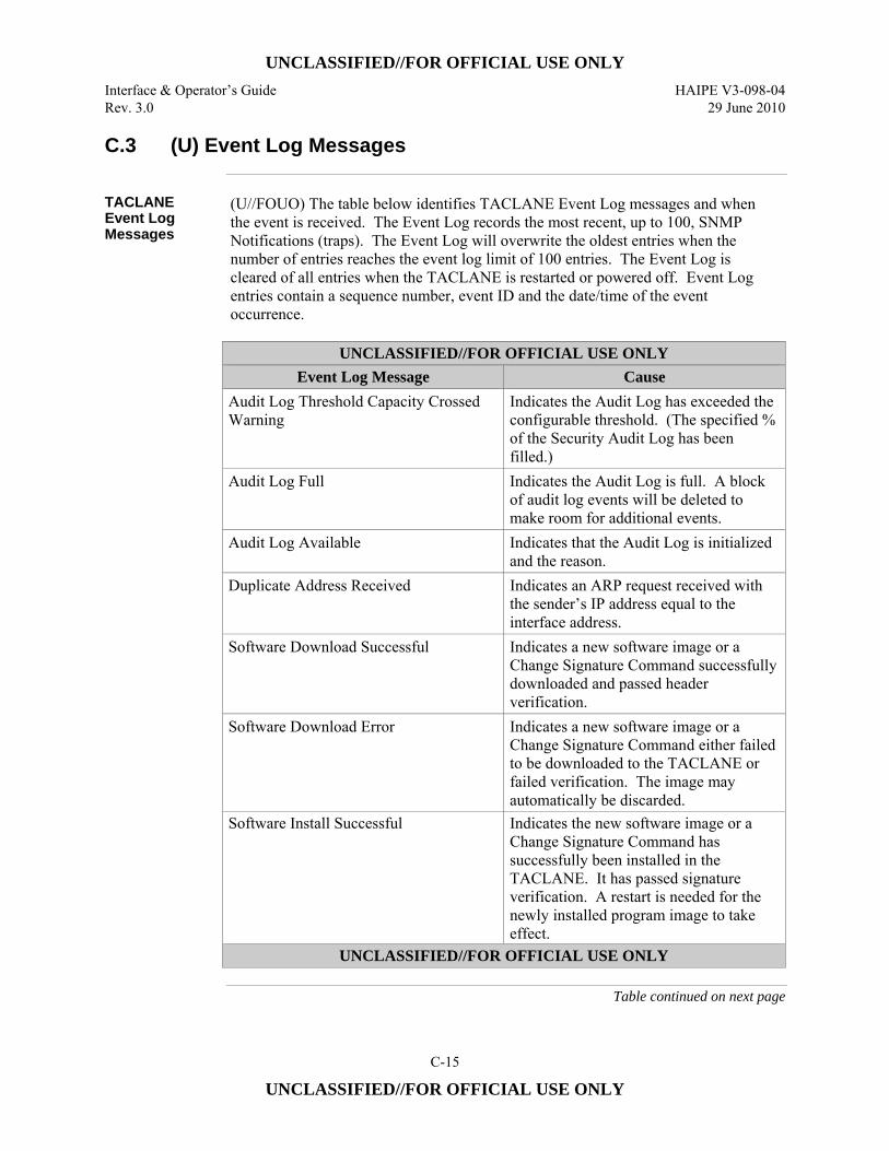
UNCLASSIFIED//FOR OFFICIAL USE ONLY
Interface & Operator’s Guide HAIPE V3-098-04 Rev. 3.0 29 June 2010
C-15
UNCLASSIFIED//FOR OFFICIAL USE ONLY
C.3 (U) Event Log Messages
TACLANE Event Log Messages
(U//FOUO) The table below identifies TACLANE Event Log messages and when the event is received. The Event Log records the most recent, up to 100, SNMP Notifications (traps). The Event Log will overwrite the oldest entries when the number of entries reaches the event log limit of 100 entries. The Event Log is cleared of all entries when the TACLANE is restarted or powered off. Event Log entries contain a sequence number, event ID and the date/time of the event occurrence.
UNCLASSIFIED//FOR OFFICIAL USE ONLY
Event Log Message Cause Audit Log Threshold Capacity Crossed Warning
Indicates the Audit Log has exceeded the configurable threshold. (The specified % of the Security Audit Log has been filled.)
Audit Log Full Indicates the Audit Log is full. A block of audit log events will be deleted to make room for additional events.
Audit Log Available Indicates that the Audit Log is initialized and the reason.
Duplicate Address Received Indicates an ARP request received with the sender’s IP address equal to the interface address.
Software Download Successful Indicates a new software image or a Change Signature Command successfully downloaded and passed header verification.
Software Download Error Indicates a new software image or a Change Signature Command either failed to be downloaded to the TACLANE or failed verification. The image may automatically be discarded.
Software Install Successful Indicates the new software image or a Change Signature Command has successfully been installed in the TACLANE. It has passed signature verification. A restart is needed for the newly installed program image to take effect.
UNCLASSIFIED//FOR OFFICIAL USE ONLY
Table continued on next page
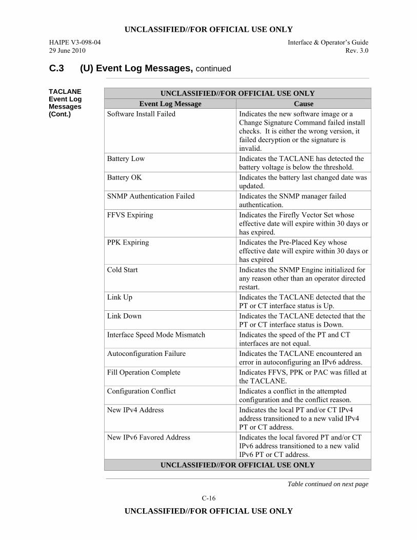
UNCLASSIFIED//FOR OFFICIAL USE ONLY
HAIPE V3-098-04 Interface & Operator’s Guide 29 June 2010 Rev. 3.0
C-16
UNCLASSIFIED//FOR OFFICIAL USE ONLY
C.3 (U) Event Log Messages, continued
TACLANE Event Log Messages (Cont.)
UNCLASSIFIED//FOR OFFICIAL USE ONLY Event Log Message Cause
Software Install Failed Indicates the new software image or a Change Signature Command failed install checks. It is either the wrong version, it failed decryption or the signature is invalid.
Battery Low Indicates the TACLANE has detected the battery voltage is below the threshold.
Battery OK Indicates the battery last changed date was updated.
SNMP Authentication Failed Indicates the SNMP manager failed authentication.
FFVS Expiring Indicates the Firefly Vector Set whose effective date will expire within 30 days or has expired.
PPK Expiring Indicates the Pre-Placed Key whose effective date will expire within 30 days or has expired
Cold Start Indicates the SNMP Engine initialized for any reason other than an operator directed restart.
Link Up Indicates the TACLANE detected that the PT or CT interface status is Up.
Link Down Indicates the TACLANE detected that the PT or CT interface status is Down.
Interface Speed Mode Mismatch Indicates the speed of the PT and CT interfaces are not equal.
Autoconfiguration Failure Indicates the TACLANE encountered an error in autoconfiguring an IPv6 address.
Fill Operation Complete Indicates FFVS, PPK or PAC was filled at the TACLANE.
Configuration Conflict Indicates a conflict in the attempted configuration and the conflict reason.
New IPv4 Address Indicates the local PT and/or CT IPv4 address transitioned to a new valid IPv4 PT or CT address.
New IPv6 Favored Address Indicates the local favored PT and/or CT IPv6 address transitioned to a new valid IPv6 PT or CT address.
UNCLASSIFIED//FOR OFFICIAL USE ONLY
Table continued on next page
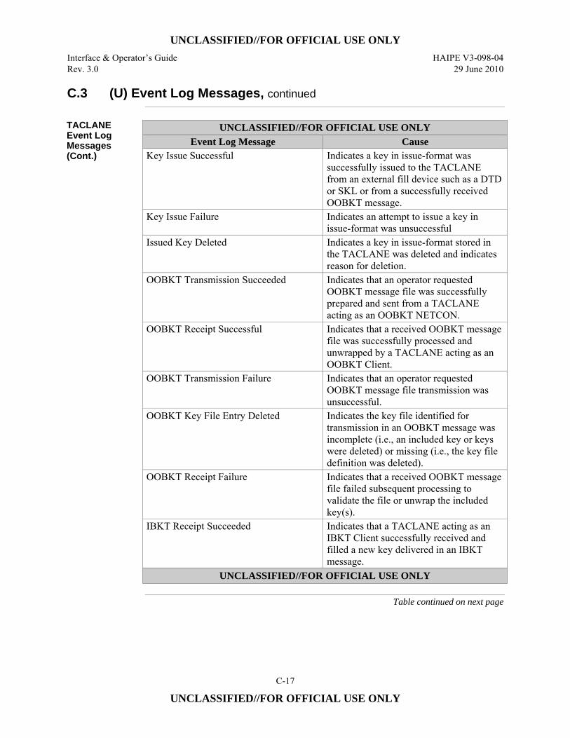
UNCLASSIFIED//FOR OFFICIAL USE ONLY
Interface & Operator’s Guide HAIPE V3-098-04 Rev. 3.0 29 June 2010
C-17
UNCLASSIFIED//FOR OFFICIAL USE ONLY
C.3 (U) Event Log Messages, continued
TACLANE Event Log Messages (Cont.)
UNCLASSIFIED//FOR OFFICIAL USE ONLY Event Log Message Cause
Key Issue Successful Indicates a key in issue-format was successfully issued to the TACLANE from an external fill device such as a DTD or SKL or from a successfully received OOBKT message.
Key Issue Failure Indicates an attempt to issue a key in issue-format was unsuccessful
Issued Key Deleted Indicates a key in issue-format stored in the TACLANE was deleted and indicates reason for deletion.
OOBKT Transmission Succeeded Indicates that an operator requested OOBKT message file was successfully prepared and sent from a TACLANE acting as an OOBKT NETCON.
OOBKT Receipt Successful Indicates that a received OOBKT message file was successfully processed and unwrapped by a TACLANE acting as an OOBKT Client.
OOBKT Transmission Failure Indicates that an operator requested OOBKT message file transmission was unsuccessful.
OOBKT Key File Entry Deleted Indicates the key file identified for transmission in an OOBKT message was incomplete (i.e., an included key or keys were deleted) or missing (i.e., the key file definition was deleted).
OOBKT Receipt Failure Indicates that a received OOBKT message file failed subsequent processing to validate the file or unwrap the included key(s).
IBKT Receipt Succeeded Indicates that a TACLANE acting as an IBKT Client successfully received and filled a new key delivered in an IBKT message.
UNCLASSIFIED//FOR OFFICIAL USE ONLY
Table continued on next page
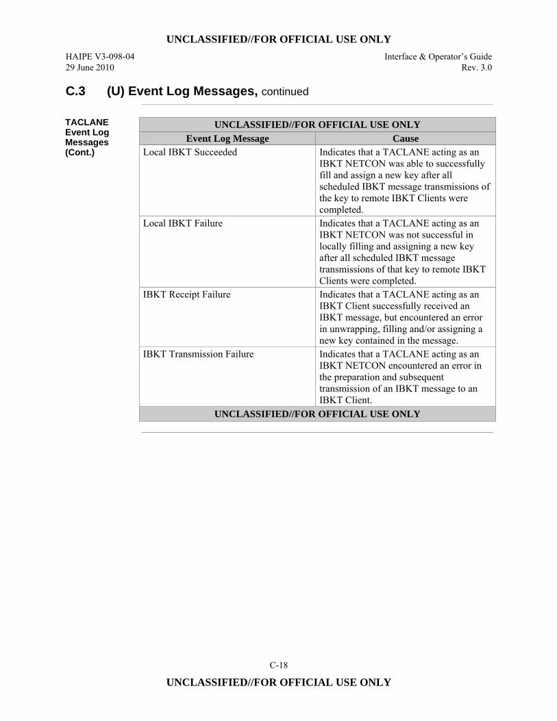
UNCLASSIFIED//FOR OFFICIAL USE ONLY
HAIPE V3-098-04 Interface & Operator’s Guide 29 June 2010 Rev. 3.0
C-18
UNCLASSIFIED//FOR OFFICIAL USE ONLY
C.3 (U) Event Log Messages, continued
TACLANE Event Log Messages (Cont.)
UNCLASSIFIED//FOR OFFICIAL USE ONLY Event Log Message Cause
Local IBKT Succeeded Indicates that a TACLANE acting as an IBKT NETCON was able to successfully fill and assign a new key after all scheduled IBKT message transmissions of the key to remote IBKT Clients were completed.
Local IBKT Failure Indicates that a TACLANE acting as an IBKT NETCON was not successful in locally filling and assigning a new key after all scheduled IBKT message transmissions of that key to remote IBKT Clients were completed.
IBKT Receipt Failure Indicates that a TACLANE acting as an IBKT Client successfully received an IBKT message, but encountered an error in unwrapping, filling and/or assigning a new key contained in the message.
IBKT Transmission Failure Indicates that a TACLANE acting as an IBKT NETCON encountered an error in the preparation and subsequent transmission of an IBKT message to an IBKT Client.
UNCLASSIFIED//FOR OFFICIAL USE ONLY
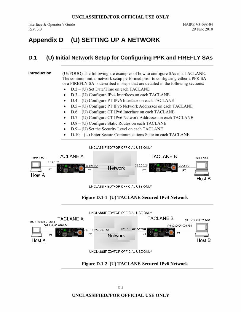
UNCLASSIFIED//FOR OFFICIAL USE ONLY
Interface & Operator’s Guide HAIPE V3-098-04 Rev. 3.0 29 June 2010
D-1
UNCLASSIFIED//FOR OFFICIAL USE ONLY
Appendix D (U) SETTING UP A NETWORK
D.1 (U) Initial Network Setup for Configuring PPK and FIREFLY SAs
Introduction (U//FOUO) The following are examples of how to configure SAs in a TACLANE.
The common initial network setup performed prior to configuring either a PPK SA or a FIREFLY SA is described in steps that are detailed in the following sections: • D.2 – (U) Set Date/Time on each TACLANE • D.3 – (U) Configure IPv4 Interfaces on each TACLANE • D.4 – (U) Configure PT IPv6 Interface on each TACLANE • D.5 – (U) Configure PT IPv6 Network Addresses on each TACLANE • D.6 – (U) Configure CT IPv6 Interface on each TACLANE • D.7 – (U) Configure CT IPv6 Network Addresses on each TACLANE • D.8 – (U) Configure Static Routes on each TACLANE • D.9 – (U) Set the Security Level on each TACLANE • D.10 – (U) Enter Secure Communications State on each TACLANE
Figure D.1-1 (U) TACLANE-Secured IPv4 Network
Figure D.1-2 (U) TACLANE-Secured IPv6 Network
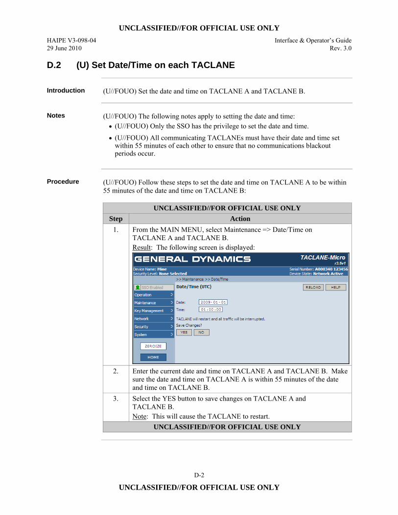
UNCLASSIFIED//FOR OFFICIAL USE ONLY
HAIPE V3-098-04 Interface & Operator’s Guide 29 June 2010 Rev. 3.0
D-2
UNCLASSIFIED//FOR OFFICIAL USE ONLY
D.2 (U) Set Date/Time on each TACLANE
Introduction (U//FOUO) Set the date and time on TACLANE A and TACLANE B.
Notes (U//FOUO) The following notes apply to setting the date and time:
• (U//FOUO) Only the SSO has the privilege to set the date and time. • (U//FOUO) All communicating TACLANEs must have their date and time set
within 55 minutes of each other to ensure that no communications blackout periods occur.
Procedure (U//FOUO) Follow these steps to set the date and time on TACLANE A to be within
55 minutes of the date and time on TACLANE B:
UNCLASSIFIED//FOR OFFICIAL USE ONLY Step Action
1. From the MAIN MENU, select Maintenance => Date/Time on TACLANE A and TACLANE B. Result: The following screen is displayed:
2. Enter the current date and time on TACLANE A and TACLANE B. Make sure the date and time on TACLANE A is within 55 minutes of the date and time on TACLANE B.
3. Select the YES button to save changes on TACLANE A and TACLANE B. Note: This will cause the TACLANE to restart.
UNCLASSIFIED//FOR OFFICIAL USE ONLY

UNCLASSIFIED//FOR OFFICIAL USE ONLY
Interface & Operator’s Guide HAIPE V3-098-04 Rev. 3.0 29 June 2010
D-3
UNCLASSIFIED//FOR OFFICIAL USE ONLY
D.3 (U) Configure IPv4 Interfaces on each TACLANE
Introduction (U//FOUO) Configure the PT and CT IPv4 interfaces on TACLANE A and
TACLANE B.
Notes (U//FOUO) The following notes apply to entering/modifying the TACLANE IP
addresses: • (U//FOUO) The CT and PT IP addresses must include the prefix length in the
format /XX as a suffix to the IPv4 address. [XX is the number of bits of the IPv4 address that are used by the prefix (subnet mask)].
Procedure (U//FOUO) Follow these steps to configure the PT and CT IPv4 interfaces on
TACLANE A and TACLANE B:
UNCLASSIFIED//FOR OFFICIAL USE ONLY Step Action
1. From the MAIN MENU, select Network => IPv4 Comm on TACLANE A and TACLANE B. Result: The following screen is displayed:
UNCLASSIFIED//FOR OFFICIAL USE ONLY
Table continued on next page
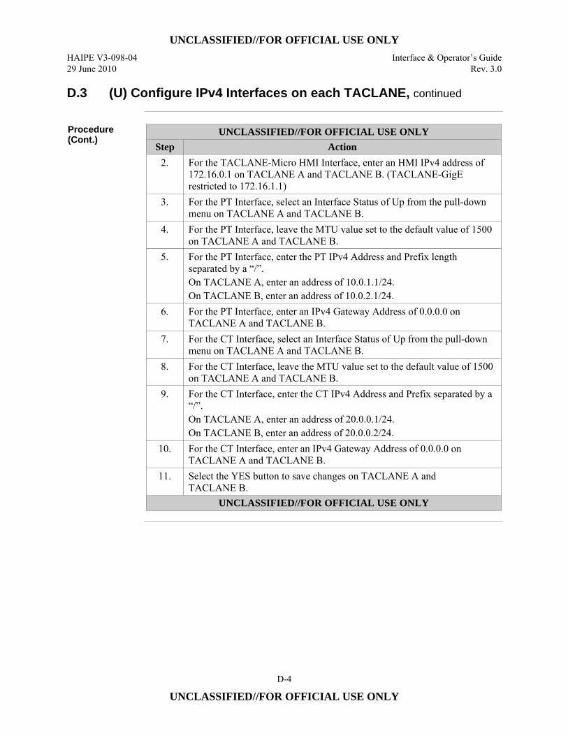
UNCLASSIFIED//FOR OFFICIAL USE ONLY
HAIPE V3-098-04 Interface & Operator’s Guide 29 June 2010 Rev. 3.0
D-4
UNCLASSIFIED//FOR OFFICIAL USE ONLY
D.3 (U) Configure IPv4 Interfaces on each TACLANE, continued
Procedure (Cont.)
UNCLASSIFIED//FOR OFFICIAL USE ONLY Step Action
2. For the TACLANE-Micro HMI Interface, enter an HMI IPv4 address of 172.16.0.1 on TACLANE A and TACLANE B. (TACLANE-GigE restricted to 172.16.1.1)
3. For the PT Interface, select an Interface Status of Up from the pull-down menu on TACLANE A and TACLANE B.
4. For the PT Interface, leave the MTU value set to the default value of 1500 on TACLANE A and TACLANE B.
5. For the PT Interface, enter the PT IPv4 Address and Prefix length separated by a “/”. On TACLANE A, enter an address of 10.0.1.1/24. On TACLANE B, enter an address of 10.0.2.1/24.
6. For the PT Interface, enter an IPv4 Gateway Address of 0.0.0.0 on TACLANE A and TACLANE B.
7. For the CT Interface, select an Interface Status of Up from the pull-down menu on TACLANE A and TACLANE B.
8. For the CT Interface, leave the MTU value set to the default value of 1500 on TACLANE A and TACLANE B.
9. For the CT Interface, enter the CT IPv4 Address and Prefix separated by a “/”. On TACLANE A, enter an address of 20.0.0.1/24. On TACLANE B, enter an address of 20.0.0.2/24.
10. For the CT Interface, enter an IPv4 Gateway Address of 0.0.0.0 on TACLANE A and TACLANE B.
11. Select the YES button to save changes on TACLANE A and TACLANE B.
UNCLASSIFIED//FOR OFFICIAL USE ONLY
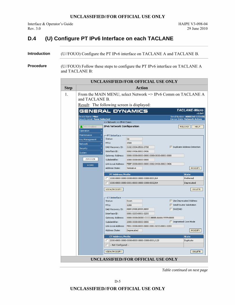
UNCLASSIFIED//FOR OFFICIAL USE ONLY
Interface & Operator’s Guide HAIPE V3-098-04 Rev. 3.0 29 June 2010
D-5
UNCLASSIFIED//FOR OFFICIAL USE ONLY
D.4 (U) Configure PT IPv6 Interface on each TACLANE
Introduction (U//FOUO) Configure the PT IPv6 interface on TACLANE A and TACLANE B.
Procedure (U//FOUO) Follow these steps to configure the PT IPv6 interface on TACLANE A
and TACLANE B:
UNCLASSIFIED//FOR OFFICIAL USE ONLY Step Action 1. From the MAIN MENU, select Network => IPv6 Comm on TACLANE A
and TACLANE B. Result: The following screen is displayed:
UNCLASSIFIED//FOR OFFICIAL USE ONLY
Table continued on next page
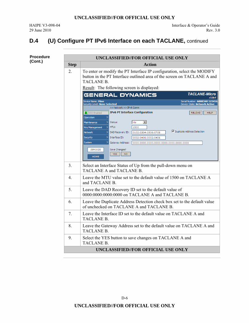
UNCLASSIFIED//FOR OFFICIAL USE ONLY
HAIPE V3-098-04 Interface & Operator’s Guide 29 June 2010 Rev. 3.0
D-6
UNCLASSIFIED//FOR OFFICIAL USE ONLY
D.4 (U) Configure PT IPv6 Interface on each TACLANE, continued
Procedure (Cont.)
UNCLASSIFIED//FOR OFFICIAL USE ONLY Step Action 2. To enter or modify the PT Interface IP configuration, select the MODIFY
button in the PT Interface outlined area of the screen on TACLANE A and TACLANE B. Result: The following screen is displayed:
3. Select an Interface Status of Up from the pull-down menu on TACLANE A and TACLANE B.
4. Leave the MTU value set to the default value of 1500 on TACLANE A and TACLANE B.
5. Leave the DAD Recovery ID set to the default value of 0000:0000:0000:0000 on TACLANE A and TACLANE B.
6. Leave the Duplicate Address Detection check box set to the default value of unchecked on TACLANE A and TACLANE B.
7. Leave the Interface ID set to the default value on TACLANE A and TACLANE B.
8. Leave the Gateway Address set to the default value on TACLANE A and TACLANE B.
9. Select the YES button to save changes on TACLANE A and TACLANE B.
UNCLASSIFIED//FOR OFFICIAL USE ONLY
UNCLASSIFIED//FOR OFFICIAL USE ONLY
Interface & Operator’s Guide HAIPE V3-098-04 Rev. 3.0 29 June 2010
D-7
UNCLASSIFIED//FOR OFFICIAL USE ONLY
D.5 (U) Configure PT IPv6 Network Addresses on each TACLANE
Introduction (U//FOUO) Configure the PT IPv6 network addresses on TACLANE A and
TACLANE B.
Notes (U//FOUO) The following notes apply to configuring the TACLANE IP addresses:
• (U//FOUO) The PT IPv6 addresses must include the prefix length.
Continued on next page

UNCLASSIFIED//FOR OFFICIAL USE ONLY
HAIPE V3-098-04 Interface & Operator’s Guide 29 June 2010 Rev. 3.0
D-8
UNCLASSIFIED//FOR OFFICIAL USE ONLY
D.5 (U) Configure PT IPv6 Network Addresses on each TACLANE, continued
Procedure (U//FOUO) Follow these steps to configure the PT IPv6 network addresses on
TACLANE A and TACLANE B:
UNCLASSIFIED//FOR OFFICIAL USE ONLY Step Action 1. From the MAIN MENU, select Network => IPv6 Comm on TACLANE A
and TACLANE B. Result: The following screen is displayed:
UNCLASSIFIED//FOR OFFICIAL USE ONLY
Table continued on next page
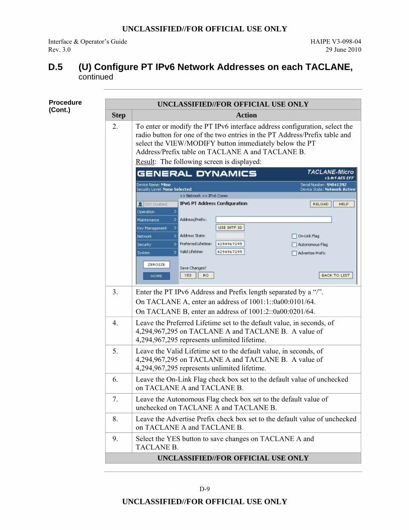
UNCLASSIFIED//FOR OFFICIAL USE ONLY
Interface & Operator’s Guide HAIPE V3-098-04 Rev. 3.0 29 June 2010
D-9
UNCLASSIFIED//FOR OFFICIAL USE ONLY
D.5 (U) Configure PT IPv6 Network Addresses on each TACLANE, continued
Procedure (Cont.)
UNCLASSIFIED//FOR OFFICIAL USE ONLY Step Action 2. To enter or modify the PT IPv6 interface address configuration, select the
radio button for one of the two entries in the PT Address/Prefix table and select the VIEW/MODIFY button immediately below the PT Address/Prefix table on TACLANE A and TACLANE B. Result: The following screen is displayed:
3. Enter the PT IPv6 Address and Prefix length separated by a “/”. On TACLANE A, enter an address of 1001:1::0a00:0101/64. On TACLANE B, enter an address of 1001:2::0a00:0201/64.
4. Leave the Preferred Lifetime set to the default value, in seconds, of 4,294,967,295 on TACLANE A and TACLANE B. A value of 4,294,967,295 represents unlimited lifetime.
5. Leave the Valid Lifetime set to the default value, in seconds, of 4,294,967,295 on TACLANE A and TACLANE B. A value of 4,294,967,295 represents unlimited lifetime.
6. Leave the On-Link Flag check box set to the default value of unchecked on TACLANE A and TACLANE B.
7. Leave the Autonomous Flag check box set to the default value of unchecked on TACLANE A and TACLANE B.
8. Leave the Advertise Prefix check box set to the default value of unchecked on TACLANE A and TACLANE B.
9. Select the YES button to save changes on TACLANE A and TACLANE B.
UNCLASSIFIED//FOR OFFICIAL USE ONLY
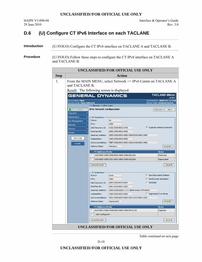
UNCLASSIFIED//FOR OFFICIAL USE ONLY
HAIPE V3-098-04 Interface & Operator’s Guide 29 June 2010 Rev. 3.0
D-10
UNCLASSIFIED//FOR OFFICIAL USE ONLY
D.6 (U) Configure CT IPv6 Interface on each TACLANE
Introduction (U//FOUO) Configure the CT IPv6 interface on TACLANE A and TACLANE B.
Procedure (U//FOUO) Follow these steps to configure the CT IPv6 interface on TACLANE A
and TACLANE B:
UNCLASSIFIED//FOR OFFICIAL USE ONLY Step Action 1. From the MAIN MENU, select Network => IPv6 Comm on TACLANE A
and TACLANE B. Result: The following screen is displayed:
UNCLASSIFIED//FOR OFFICIAL USE ONLY
Table continued on next page
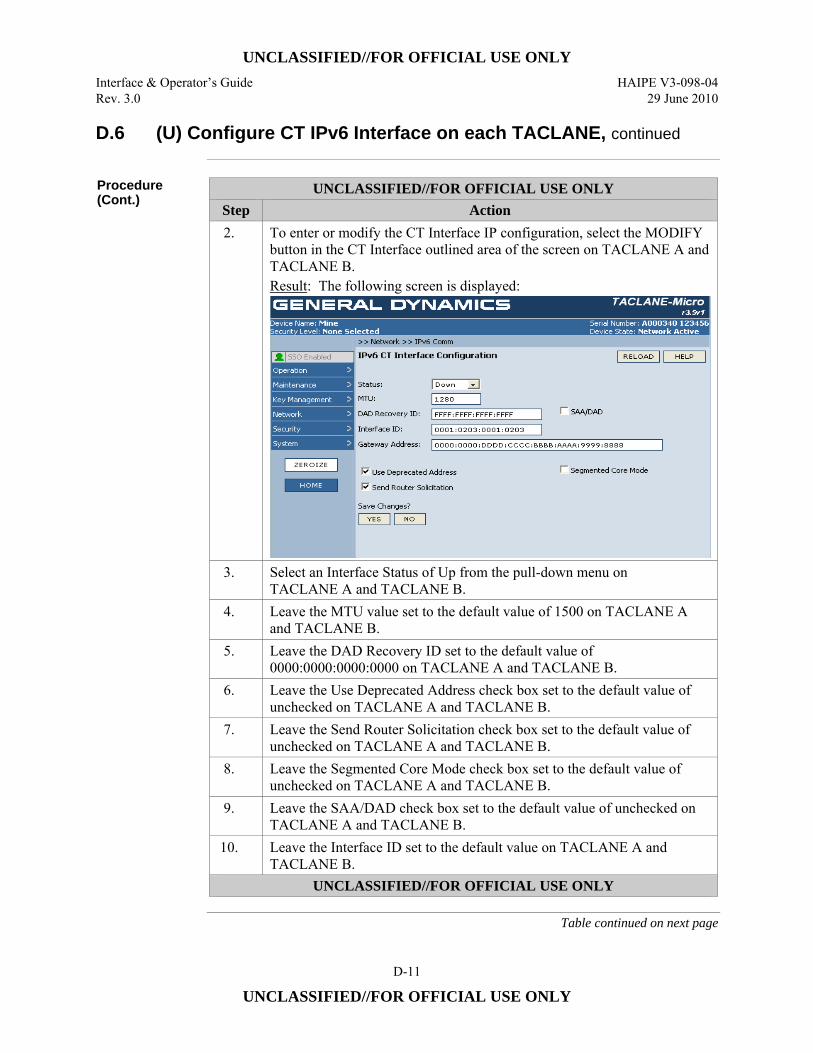
UNCLASSIFIED//FOR OFFICIAL USE ONLY
Interface & Operator’s Guide HAIPE V3-098-04 Rev. 3.0 29 June 2010
D-11
UNCLASSIFIED//FOR OFFICIAL USE ONLY
D.6 (U) Configure CT IPv6 Interface on each TACLANE, continued
Procedure (Cont.)
UNCLASSIFIED//FOR OFFICIAL USE ONLY Step Action 2. To enter or modify the CT Interface IP configuration, select the MODIFY
button in the CT Interface outlined area of the screen on TACLANE A and TACLANE B. Result: The following screen is displayed:
3. Select an Interface Status of Up from the pull-down menu on TACLANE A and TACLANE B.
4. Leave the MTU value set to the default value of 1500 on TACLANE A and TACLANE B.
5. Leave the DAD Recovery ID set to the default value of 0000:0000:0000:0000 on TACLANE A and TACLANE B.
6. Leave the Use Deprecated Address check box set to the default value of unchecked on TACLANE A and TACLANE B.
7. Leave the Send Router Solicitation check box set to the default value of unchecked on TACLANE A and TACLANE B.
8. Leave the Segmented Core Mode check box set to the default value of unchecked on TACLANE A and TACLANE B.
9. Leave the SAA/DAD check box set to the default value of unchecked on TACLANE A and TACLANE B.
10. Leave the Interface ID set to the default value on TACLANE A and TACLANE B.
UNCLASSIFIED//FOR OFFICIAL USE ONLY
Table continued on next page
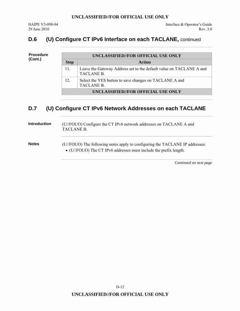
UNCLASSIFIED//FOR OFFICIAL USE ONLY
HAIPE V3-098-04 Interface & Operator’s Guide 29 June 2010 Rev. 3.0
D-12
UNCLASSIFIED//FOR OFFICIAL USE ONLY
D.6 (U) Configure CT IPv6 Interface on each TACLANE, continued
Procedure (Cont.)
UNCLASSIFIED//FOR OFFICIAL USE ONLY Step Action 11. Leave the Gateway Address set to the default value on TACLANE A and
TACLANE B. 12. Select the YES button to save changes on TACLANE A and
TACLANE B. UNCLASSIFIED//FOR OFFICIAL USE ONLY
D.7 (U) Configure CT IPv6 Network Addresses on each TACLANE
Introduction (U//FOUO) Configure the CT IPv6 network addresses on TACLANE A and
TACLANE B.
Notes (U//FOUO) The following notes apply to configuring the TACLANE IP addresses:
• (U//FOUO) The CT IPv6 addresses must include the prefix length.
Continued on next page
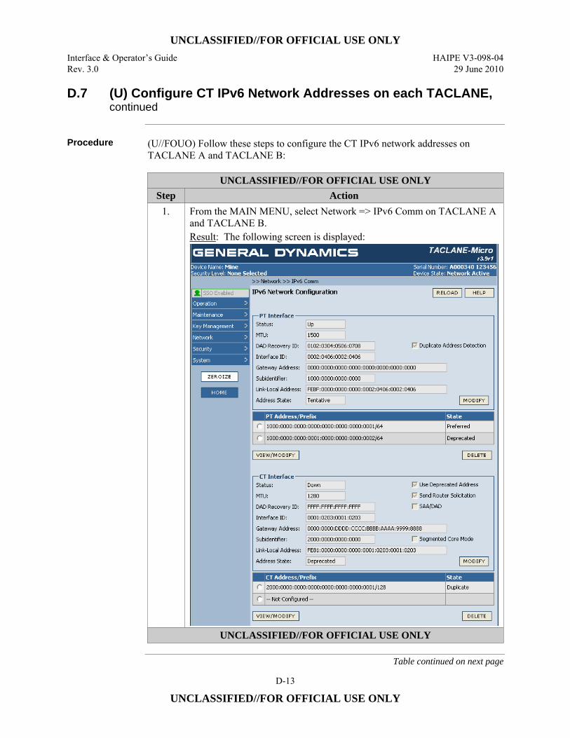
UNCLASSIFIED//FOR OFFICIAL USE ONLY
Interface & Operator’s Guide HAIPE V3-098-04 Rev. 3.0 29 June 2010
D-13
UNCLASSIFIED//FOR OFFICIAL USE ONLY
D.7 (U) Configure CT IPv6 Network Addresses on each TACLANE, continued
Procedure (U//FOUO) Follow these steps to configure the CT IPv6 network addresses on
TACLANE A and TACLANE B:
UNCLASSIFIED//FOR OFFICIAL USE ONLY Step Action
1. From the MAIN MENU, select Network => IPv6 Comm on TACLANE A and TACLANE B. Result: The following screen is displayed:
UNCLASSIFIED//FOR OFFICIAL USE ONLY
Table continued on next page
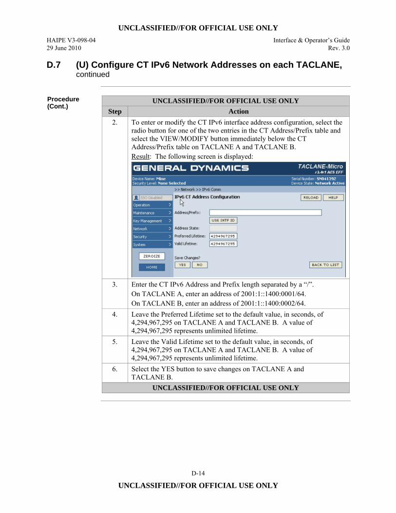
UNCLASSIFIED//FOR OFFICIAL USE ONLY
HAIPE V3-098-04 Interface & Operator’s Guide 29 June 2010 Rev. 3.0
D-14
UNCLASSIFIED//FOR OFFICIAL USE ONLY
D.7 (U) Configure CT IPv6 Network Addresses on each TACLANE, continued
Procedure (Cont.)
UNCLASSIFIED//FOR OFFICIAL USE ONLY Step Action
2. To enter or modify the CT IPv6 interface address configuration, select the radio button for one of the two entries in the CT Address/Prefix table and select the VIEW/MODIFY button immediately below the CT Address/Prefix table on TACLANE A and TACLANE B. Result: The following screen is displayed:
3. Enter the CT IPv6 Address and Prefix length separated by a “/”. On TACLANE A, enter an address of 2001:1::1400:0001/64. On TACLANE B, enter an address of 2001:1::1400:0002/64.
4. Leave the Preferred Lifetime set to the default value, in seconds, of 4,294,967,295 on TACLANE A and TACLANE B. A value of 4,294,967,295 represents unlimited lifetime.
5. Leave the Valid Lifetime set to the default value, in seconds, of 4,294,967,295 on TACLANE A and TACLANE B. A value of 4,294,967,295 represents unlimited lifetime.
6. Select the YES button to save changes on TACLANE A and TACLANE B.
UNCLASSIFIED//FOR OFFICIAL USE ONLY
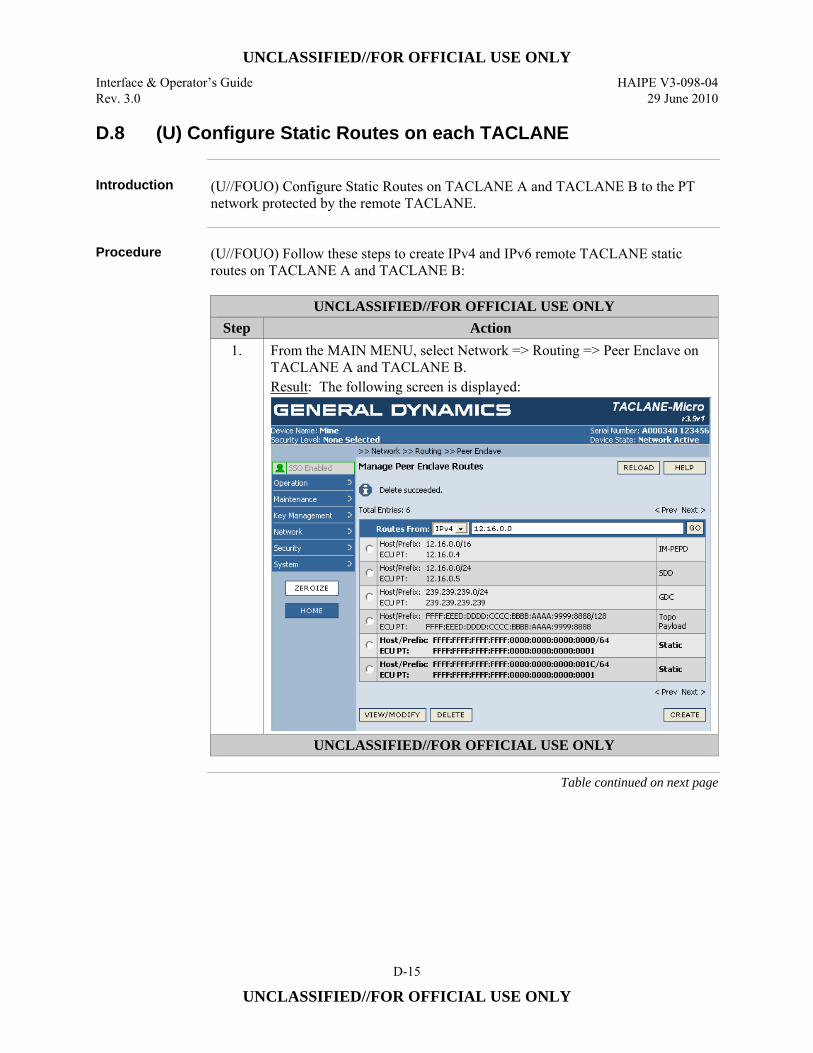
UNCLASSIFIED//FOR OFFICIAL USE ONLY
Interface & Operator’s Guide HAIPE V3-098-04 Rev. 3.0 29 June 2010
D-15
UNCLASSIFIED//FOR OFFICIAL USE ONLY
D.8 (U) Configure Static Routes on each TACLANE
Introduction (U//FOUO) Configure Static Routes on TACLANE A and TACLANE B to the PT
network protected by the remote TACLANE.
Procedure (U//FOUO) Follow these steps to create IPv4 and IPv6 remote TACLANE static
routes on TACLANE A and TACLANE B:
UNCLASSIFIED//FOR OFFICIAL USE ONLY Step Action
1. From the MAIN MENU, select Network => Routing => Peer Enclave on TACLANE A and TACLANE B. Result: The following screen is displayed:
UNCLASSIFIED//FOR OFFICIAL USE ONLY
Table continued on next page

UNCLASSIFIED//FOR OFFICIAL USE ONLY
HAIPE V3-098-04 Interface & Operator’s Guide 29 June 2010 Rev. 3.0
D-16
UNCLASSIFIED//FOR OFFICIAL USE ONLY
D.8 (U) Configure Static Routes on each TACLANE, continued
Procedure (Cont.)
UNCLASSIFIED//FOR OFFICIAL USE ONLY Step Action
2. To create a new IPv4 Static Route, select the CREATE button on TACLANE A and TACLANE B. Result: The following screen is displayed:
3. Select an IP Address Type of IPv4 on TACLANE A and TACLANE B. 4. Enter the Host Address of the remote host.
On TACLANE A, enter the address of Host B (10.0.2.0). On TACLANE B, enter the address of Host A (10.0.1.0).
5. Enter a Host Prefix of 24 on TACLANE A and TACLANE B. 6. Enter the ECU CT Address of the remote TACLANE.
On TACLANE A, enter the CT Address of TACLANE B (20.0.0.2). On TACLANE B, enter the CT Address of TACLANE A (20.0.0.1).
7. Enter the ECU PT Address of the remote TACLANE. On TACLANE A, enter the PT Address of TACLANE B (10.0.2.1). On TACLANE B, enter the PT Address of TACLANE A (10.0.1.1).
8. Enter an Admin Cost between 0 and 256 on TACLANE A and TACLANE B.
9. Enter a Lifetime date and time well in the future on TACLANE A and TACLANE B. Format is YYYY-MM-DD T HH:MM:SS.
10. Select the YES button to save changes on TACLANE A and TACLANE B.
UNCLASSIFIED//FOR OFFICIAL USE ONLY
Table continued on next page
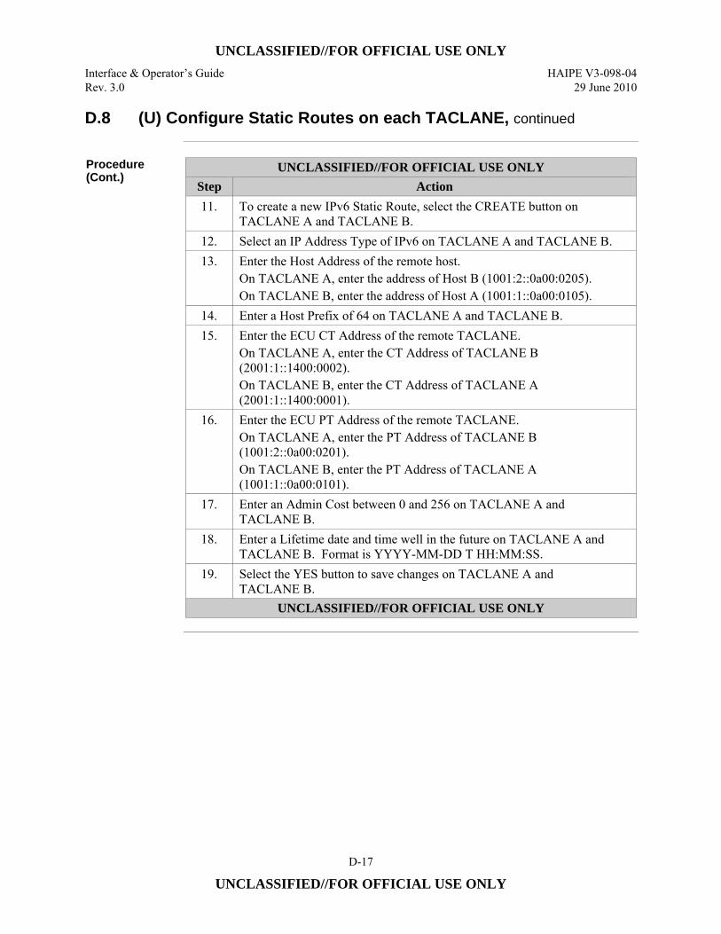
UNCLASSIFIED//FOR OFFICIAL USE ONLY
Interface & Operator’s Guide HAIPE V3-098-04 Rev. 3.0 29 June 2010
D-17
UNCLASSIFIED//FOR OFFICIAL USE ONLY
D.8 (U) Configure Static Routes on each TACLANE, continued
Procedure (Cont.)
UNCLASSIFIED//FOR OFFICIAL USE ONLY Step Action 11. To create a new IPv6 Static Route, select the CREATE button on
TACLANE A and TACLANE B. 12. Select an IP Address Type of IPv6 on TACLANE A and TACLANE B. 13. Enter the Host Address of the remote host.
On TACLANE A, enter the address of Host B (1001:2::0a00:0205). On TACLANE B, enter the address of Host A (1001:1::0a00:0105).
14. Enter a Host Prefix of 64 on TACLANE A and TACLANE B. 15. Enter the ECU CT Address of the remote TACLANE.
On TACLANE A, enter the CT Address of TACLANE B (2001:1::1400:0002). On TACLANE B, enter the CT Address of TACLANE A (2001:1::1400:0001).
16. Enter the ECU PT Address of the remote TACLANE. On TACLANE A, enter the PT Address of TACLANE B (1001:2::0a00:0201). On TACLANE B, enter the PT Address of TACLANE A (1001:1::0a00:0101).
17. Enter an Admin Cost between 0 and 256 on TACLANE A and TACLANE B.
18. Enter a Lifetime date and time well in the future on TACLANE A and TACLANE B. Format is YYYY-MM-DD T HH:MM:SS.
19. Select the YES button to save changes on TACLANE A and TACLANE B.
UNCLASSIFIED//FOR OFFICIAL USE ONLY
UNCLASSIFIED//FOR OFFICIAL USE ONLY
HAIPE V3-098-04 Interface & Operator’s Guide 29 June 2010 Rev. 3.0
D-18
UNCLASSIFIED//FOR OFFICIAL USE ONLY
D.9 (U) Set the Security Level on each TACLANE
Introduction (U//FOUO) Set the security level on TACLANE A and TACLANE B to the security
level of the key to be used.
Notes (U//FOUO) The following notes apply to selecting a security level:
• (U//FOUO) Only the SSO can access this command. • (U//FOUO) The FIREFLY vector set may only be used to generate FIREFLY
TEKs if the selected security level matches the classification level supported by the FFVS.
• (U//FOUO) PPKs may only be used at the security level matching the PPK classification.
Continued on next page
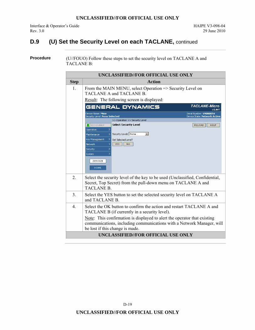
UNCLASSIFIED//FOR OFFICIAL USE ONLY
Interface & Operator’s Guide HAIPE V3-098-04 Rev. 3.0 29 June 2010
D-19
UNCLASSIFIED//FOR OFFICIAL USE ONLY
D.9 (U) Set the Security Level on each TACLANE, continued
Procedure (U//FOUO) Follow these steps to set the security level on TACLANE A and
TACLANE B:
UNCLASSIFIED//FOR OFFICIAL USE ONLY Step Action
1. From the MAIN MENU, select Operation => Security Level on TACLANE A and TACLANE B. Result: The following screen is displayed:
2. Select the security level of the key to be used (Unclassified, Confidential, Secret, Top Secret) from the pull-down menu on TACLANE A and TACLANE B.
3. Select the YES button to set the selected security level on TACLANE A and TACLANE B.
4. Select the OK button to confirm the action and restart TACLANE A and TACLANE B (if currently in a security level). Note: This confirmation is displayed to alert the operator that existing communications, including communications with a Network Manager, will be lost if this change is made.
UNCLASSIFIED//FOR OFFICIAL USE ONLY
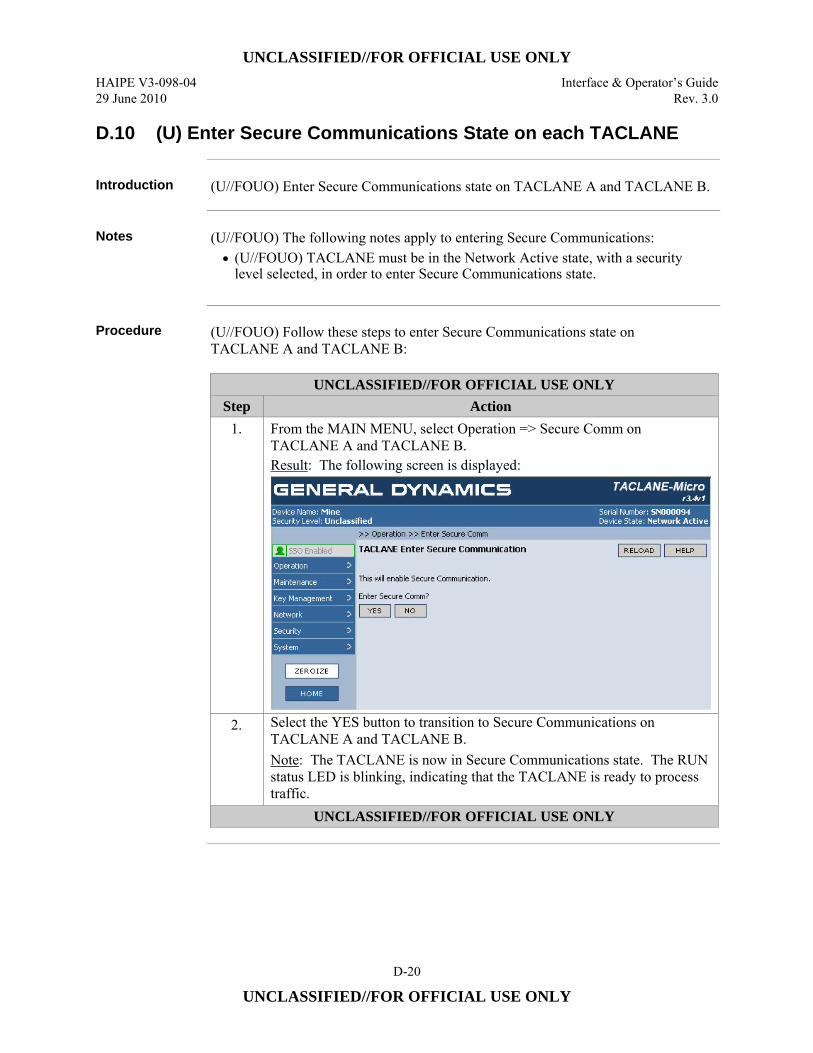
UNCLASSIFIED//FOR OFFICIAL USE ONLY
HAIPE V3-098-04 Interface & Operator’s Guide 29 June 2010 Rev. 3.0
D-20
UNCLASSIFIED//FOR OFFICIAL USE ONLY
D.10 (U) Enter Secure Communications State on each TACLANE
Introduction (U//FOUO) Enter Secure Communications state on TACLANE A and TACLANE B.
Notes (U//FOUO) The following notes apply to entering Secure Communications:
• (U//FOUO) TACLANE must be in the Network Active state, with a security level selected, in order to enter Secure Communications state.
Procedure (U//FOUO) Follow these steps to enter Secure Communications state on
TACLANE A and TACLANE B:
UNCLASSIFIED//FOR OFFICIAL USE ONLY Step Action
1. From the MAIN MENU, select Operation => Secure Comm on TACLANE A and TACLANE B. Result: The following screen is displayed:
2. Select the YES button to transition to Secure Communications on TACLANE A and TACLANE B. Note: The TACLANE is now in Secure Communications state. The RUN status LED is blinking, indicating that the TACLANE is ready to process traffic.
UNCLASSIFIED//FOR OFFICIAL USE ONLY
UNCLASSIFIED//FOR OFFICIAL USE ONLY
Interface & Operator’s Guide HAIPE V3-098-04 Rev. 3.0 29 June 2010
D-21
UNCLASSIFIED//FOR OFFICIAL USE ONLY
D.11 (U) Configuring IPv4 PPK SAs
Introduction (U//FOUO) This is an example of how to configure IPv4 PPK SAs in a TACLANE.
The steps necessary to set up an IPv4 Suite B PPK SA in this example are described in the following sections: • D.12 – (U) Fill Suite B PPK on each TACLANE • D.13 – (U) Create PPK Chain with the Filled PPK on each TACLANE • D.14 – (U) Create a Selector on each TACLANE (Optional) • D.15 – (U) Create a Rule on each TACLANE • D.16 – (U) Create a PPK SA on each TACLANE
D.12 (U) Fill Suite B PPK on each TACLANE
Introduction (U//FOUO) Fill the same Suite B PPK on TACLANE A and TACLANE B.
Notes (U//FOUO) The following notes apply to filling PPKs:
• (U//FOUO) One key or multiple keys can be filled into the TACLANE through one wake-up signal initiated session. There is no operator intervention needed at the TACLANE to fill keys.
Procedure (U//FOUO) Follow these steps to fill the same Suite B PPK on TACLANE A and
TACLANE B:
UNCLASSIFIED//FOR OFFICIAL USE ONLY Step Action
1. Make sure the DTD is configured to initiate a wake-up signal, or equivalent, prior to sending key material to the TACLANE.
2. Connect the DTD to TACLANE A, and fill a Suite B PPK.
3. Connect the DTD to TACLANE B, and fill the same Suite B PPK.
UNCLASSIFIED//FOR OFFICIAL USE ONLY
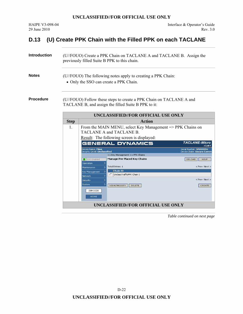
UNCLASSIFIED//FOR OFFICIAL USE ONLY
HAIPE V3-098-04 Interface & Operator’s Guide 29 June 2010 Rev. 3.0
D-22
UNCLASSIFIED//FOR OFFICIAL USE ONLY
D.13 (U) Create PPK Chain with the Filled PPK on each TACLANE
Introduction (U//FOUO) Create a PPK Chain on TACLANE A and TACLANE B. Assign the
previously filled Suite B PPK to this chain.
Notes (U//FOUO) The following notes apply to creating a PPK Chain:
• Only the SSO can create a PPK Chain.
Procedure (U//FOUO) Follow these steps to create a PPK Chain on TACLANE A and
TACLANE B, and assign the filled Suite B PPK to it:
UNCLASSIFIED//FOR OFFICIAL USE ONLY Step Action
1. From the MAIN MENU, select Key Management => PPK Chains on TACLANE A and TACLANE B. Result: The following screen is displayed:
UNCLASSIFIED//FOR OFFICIAL USE ONLY
Table continued on next page

UNCLASSIFIED//FOR OFFICIAL USE ONLY
Interface & Operator’s Guide HAIPE V3-098-04 Rev. 3.0 29 June 2010
D-23
UNCLASSIFIED//FOR OFFICIAL USE ONLY
D.13 (U) Create PPK Chain with the Filled PPK on each TACLANE, continued
Procedure (Cont.)
UNCLASSIFIED//FOR OFFICIAL USE ONLY Step Action
2. Select the CREATE button to create a PPK Chain on TACLANE A and TACLANE B. Result: The following screen is displayed:
3. Enter a Chain ID on TACLANE A and TACLANE B. 4. Select the Security Level (Unclassified, Confidential, Secret, Top Secret)
of the filled Suite B PPK from the pull-down menu on TACLANE A and TACLANE B.
5. Select a Usage Type of Traffic-PPK from the pull-down menu on TACLANE A and TACLANE B.
6. Select a Crypto Suite of Suite B from the pull-down menu on TACLANE A and TACLANE B.
7. Select an Encryption Algorithm of AES from the pull-down menu on TACLANE A and TACLANE B.
8. Enter the Effective Date (year and month) on TACLANE A and TACLANE B.
UNCLASSIFIED//FOR OFFICIAL USE ONLY
Table continued on next page
UNCLASSIFIED//FOR OFFICIAL USE ONLY
HAIPE V3-098-04 Interface & Operator’s Guide 29 June 2010 Rev. 3.0
D-24
UNCLASSIFIED//FOR OFFICIAL USE ONLY
D.13 (U) Create PPK Chain with the Filled PPK on each TACLANE, continued
Procedure (Cont.)
UNCLASSIFIED//FOR OFFICIAL USE ONLY Step Action
9. Select the previously filled Suite B PPK from the list of unassigned keys on TACLANE A and TACLANE B.
10. Select the YES button to create the chain on TACLANE A and TACLANE B.
UNCLASSIFIED//FOR OFFICIAL USE ONLY
D.14 (U) Create a Selector on each TACLANE (Optional)
Introduction (U//FOUO) Create a Selector on TACLANE A and TACLANE B to associate with a
CT OUT, Protect with PPK Rule, specifying that the IPv4 traffic being sent to the remote TACLANE must be protected using PPK.
Notes (U//FOUO) The following notes apply to creating Selectors:
• (U//FOUO) Only the SSO can access this command. • (U//FOUO) The default Selector “IPv4 Any” could be used instead of creating a
new Selector specific to these network IP Addresses.
Continued on next page
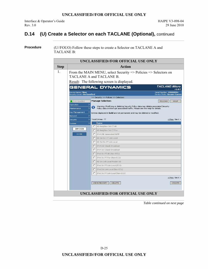
UNCLASSIFIED//FOR OFFICIAL USE ONLY
Interface & Operator’s Guide HAIPE V3-098-04 Rev. 3.0 29 June 2010
D-25
UNCLASSIFIED//FOR OFFICIAL USE ONLY
D.14 (U) Create a Selector on each TACLANE (Optional), continued
Procedure (U//FOUO) Follow these steps to create a Selector on TACLANE A and
TACLANE B:
UNCLASSIFIED//FOR OFFICIAL USE ONLY Step Action 1. From the MAIN MENU, select Security => Policies => Selectors on
TACLANE A and TACLANE B. Result: The following screen is displayed.
UNCLASSIFIED//FOR OFFICIAL USE ONLY
Table continued on next page

UNCLASSIFIED//FOR OFFICIAL USE ONLY
HAIPE V3-098-04 Interface & Operator’s Guide 29 June 2010 Rev. 3.0
D-26
UNCLASSIFIED//FOR OFFICIAL USE ONLY
D.14 (U) Create a Selector on each TACLANE (Optional), continued
Procedure (Cont.)
UNCLASSIFIED//FOR OFFICIAL USE ONLY Step Action 2. To create a new Selector, select the CREATE button on TACLANE A and
TACLANE B. Result: The following screen is displayed:
3. Enter the Name of the Selector on TACLANE A and TACLANE B. 4. Select an IP Address Type of IPv4 on TACLANE A and TACLANE B. 5. Select a Source Address Setting of Any on TACLANE A and
TACLANE B. UNCLASSIFIED//FOR OFFICIAL USE ONLY
Table continued on next page
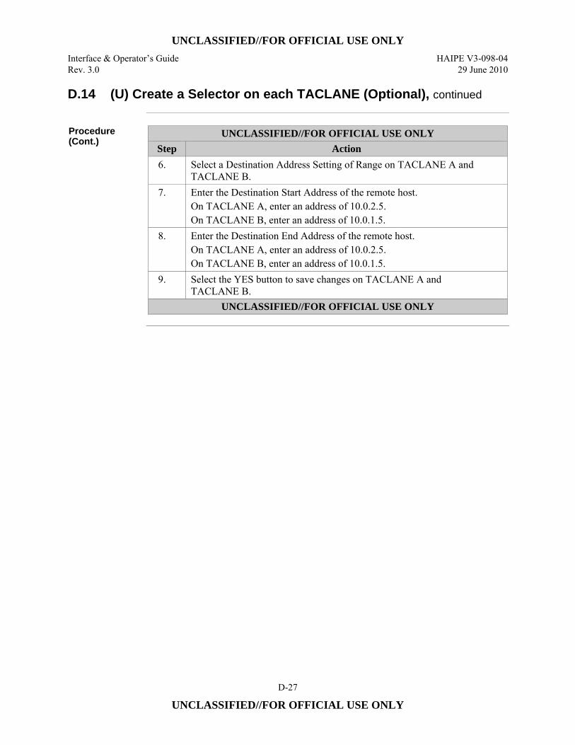
UNCLASSIFIED//FOR OFFICIAL USE ONLY
Interface & Operator’s Guide HAIPE V3-098-04 Rev. 3.0 29 June 2010
D-27
UNCLASSIFIED//FOR OFFICIAL USE ONLY
D.14 (U) Create a Selector on each TACLANE (Optional), continued
Procedure (Cont.)
UNCLASSIFIED//FOR OFFICIAL USE ONLY Step Action 6. Select a Destination Address Setting of Range on TACLANE A and
TACLANE B. 7. Enter the Destination Start Address of the remote host.
On TACLANE A, enter an address of 10.0.2.5. On TACLANE B, enter an address of 10.0.1.5.
8. Enter the Destination End Address of the remote host. On TACLANE A, enter an address of 10.0.2.5. On TACLANE B, enter an address of 10.0.1.5.
9. Select the YES button to save changes on TACLANE A and TACLANE B.
UNCLASSIFIED//FOR OFFICIAL USE ONLY
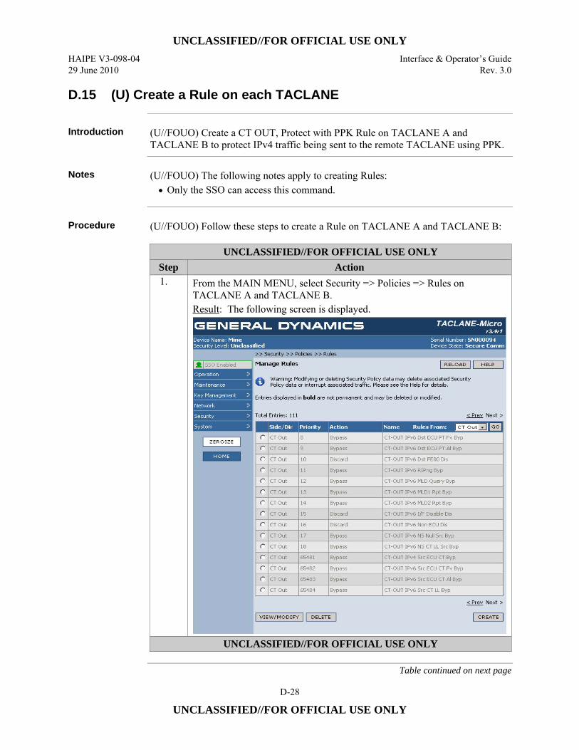
UNCLASSIFIED//FOR OFFICIAL USE ONLY
HAIPE V3-098-04 Interface & Operator’s Guide 29 June 2010 Rev. 3.0
D-28
UNCLASSIFIED//FOR OFFICIAL USE ONLY
D.15 (U) Create a Rule on each TACLANE
Introduction (U//FOUO) Create a CT OUT, Protect with PPK Rule on TACLANE A and
TACLANE B to protect IPv4 traffic being sent to the remote TACLANE using PPK.
Notes (U//FOUO) The following notes apply to creating Rules:
• Only the SSO can access this command.
Procedure (U//FOUO) Follow these steps to create a Rule on TACLANE A and TACLANE B:
UNCLASSIFIED//FOR OFFICIAL USE ONLY Step Action 1. From the MAIN MENU, select Security => Policies => Rules on
TACLANE A and TACLANE B. Result: The following screen is displayed.
UNCLASSIFIED//FOR OFFICIAL USE ONLY
Table continued on next page
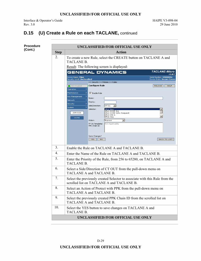
UNCLASSIFIED//FOR OFFICIAL USE ONLY
Interface & Operator’s Guide HAIPE V3-098-04 Rev. 3.0 29 June 2010
D-29
UNCLASSIFIED//FOR OFFICIAL USE ONLY
D.15 (U) Create a Rule on each TACLANE, continued
Procedure (Cont.)
UNCLASSIFIED//FOR OFFICIAL USE ONLY Step Action 2. To create a new Rule, select the CREATE button on TACLANE A and
TACLANE B. Result: The following screen is displayed:
3. Enable the Rule on TACLANE A and TACLANE B. 4. Enter the Name of the Rule on TACLANE A and TACLANE B. 5. Enter the Priority of the Rule, from 256 to 65280, on TACLANE A and
TACLANE B. 6. Select a Side/Direction of CT OUT from the pull-down menu on
TACLANE A and TACLANE B. 7. Select the previously created Selector to associate with this Rule from the
scrolled list on TACLANE A and TACLANE B. 8. Select an Action of Protect with PPK from the pull-down menu on
TACLANE A and TACLANE B. 9. Select the previously created PPK Chain ID from the scrolled list on
TACLANE A and TACLANE B. 10. Select the YES button to save changes on TACLANE A and
TACLANE B. UNCLASSIFIED//FOR OFFICIAL USE ONLY
UNCLASSIFIED//FOR OFFICIAL USE ONLY
HAIPE V3-098-04 Interface & Operator’s Guide 29 June 2010 Rev. 3.0
D-30
UNCLASSIFIED//FOR OFFICIAL USE ONLY
D.16 (U) Create a PPK SA on each TACLANE
Introduction (U//FOUO) Create a PPK SA on TACLANE A and TACLANE B to protect IPv4
traffic being sent to the remote TACLANE using PPK. (U//FOUO) The steps listed below include those necessary to create a Transport Mode PPK SA.
Notes (U//FOUO) The following notes apply to creating PPK SAs:
• (U//FOUO) Only the SSO can access this command. • (U//FOUO) Transport Mode PPK SAs cannot be created if FPL is enabled. • (U//FOUO) Transport Mode PPK SAs cannot be created with Legacy PPK
Chains • (U//FOUO) If Control Plane Signaling is not enabled for a Transport Mode PPK
SA then the Transport Mode PPK SA cannot be created unless PPK PDUN Transmit is disabled and the PPK PHRD Rate is disabled.
• (U//FOUO) A multicast Transport Mode PPK SA must be associated with a Transport Mode Address map that contains a multicast destination address.
• (U//FOUO) A unicast Transport Mode PPK SA must be associated with a Transport Mode Address map that contains a unicast destination address.
Continued on next page
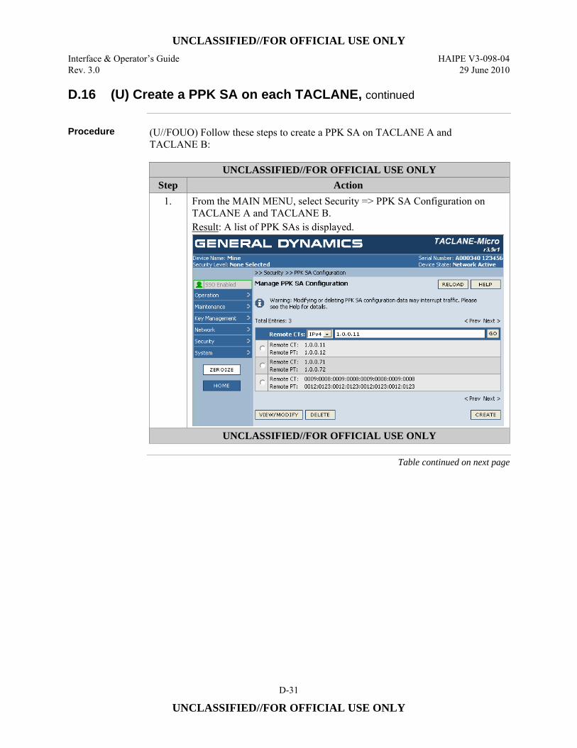
UNCLASSIFIED//FOR OFFICIAL USE ONLY
Interface & Operator’s Guide HAIPE V3-098-04 Rev. 3.0 29 June 2010
D-31
UNCLASSIFIED//FOR OFFICIAL USE ONLY
D.16 (U) Create a PPK SA on each TACLANE, continued
Procedure (U//FOUO) Follow these steps to create a PPK SA on TACLANE A and
TACLANE B:
UNCLASSIFIED//FOR OFFICIAL USE ONLY Step Action
1. From the MAIN MENU, select Security => PPK SA Configuration on TACLANE A and TACLANE B. Result: A list of PPK SAs is displayed.
UNCLASSIFIED//FOR OFFICIAL USE ONLY
Table continued on next page
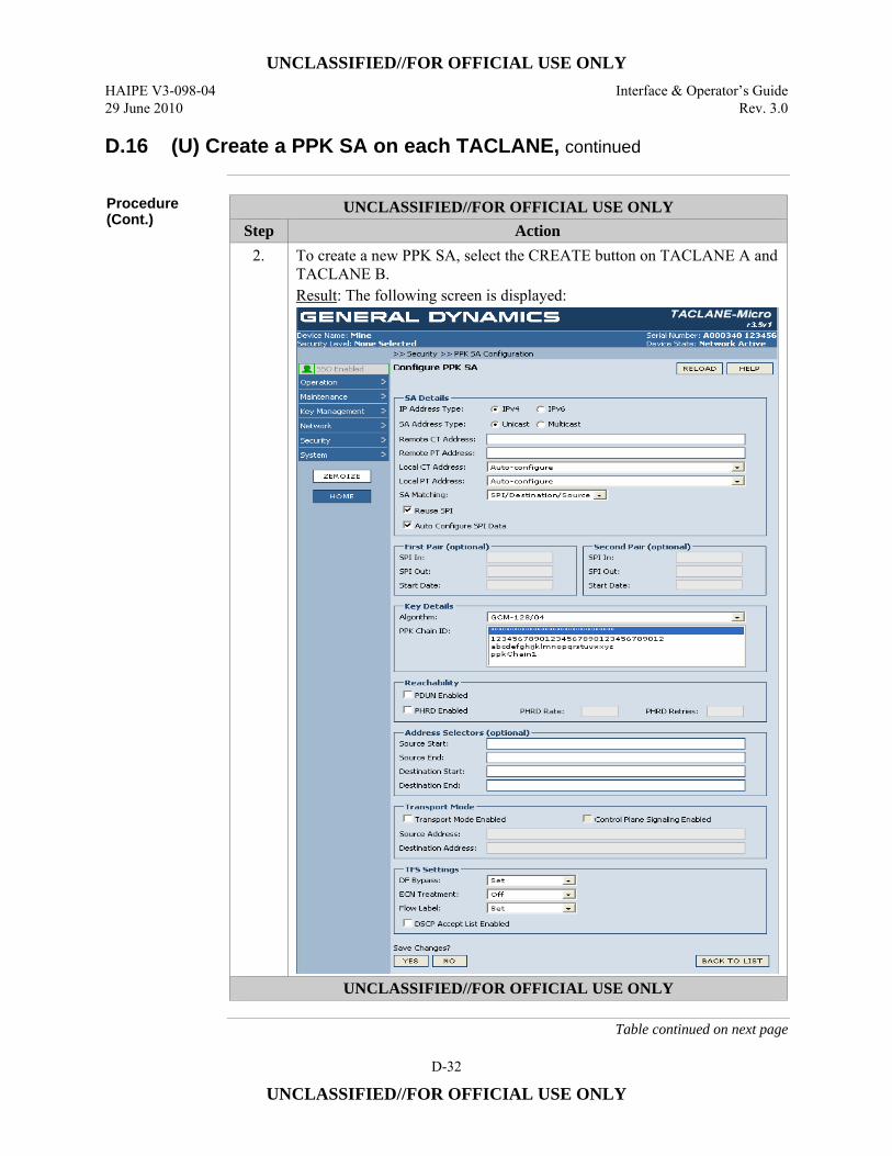
UNCLASSIFIED//FOR OFFICIAL USE ONLY
HAIPE V3-098-04 Interface & Operator’s Guide 29 June 2010 Rev. 3.0
D-32
UNCLASSIFIED//FOR OFFICIAL USE ONLY
D.16 (U) Create a PPK SA on each TACLANE, continued
Procedure (Cont.)
UNCLASSIFIED//FOR OFFICIAL USE ONLY Step Action
2. To create a new PPK SA, select the CREATE button on TACLANE A and TACLANE B. Result: The following screen is displayed:
UNCLASSIFIED//FOR OFFICIAL USE ONLY
Table continued on next page
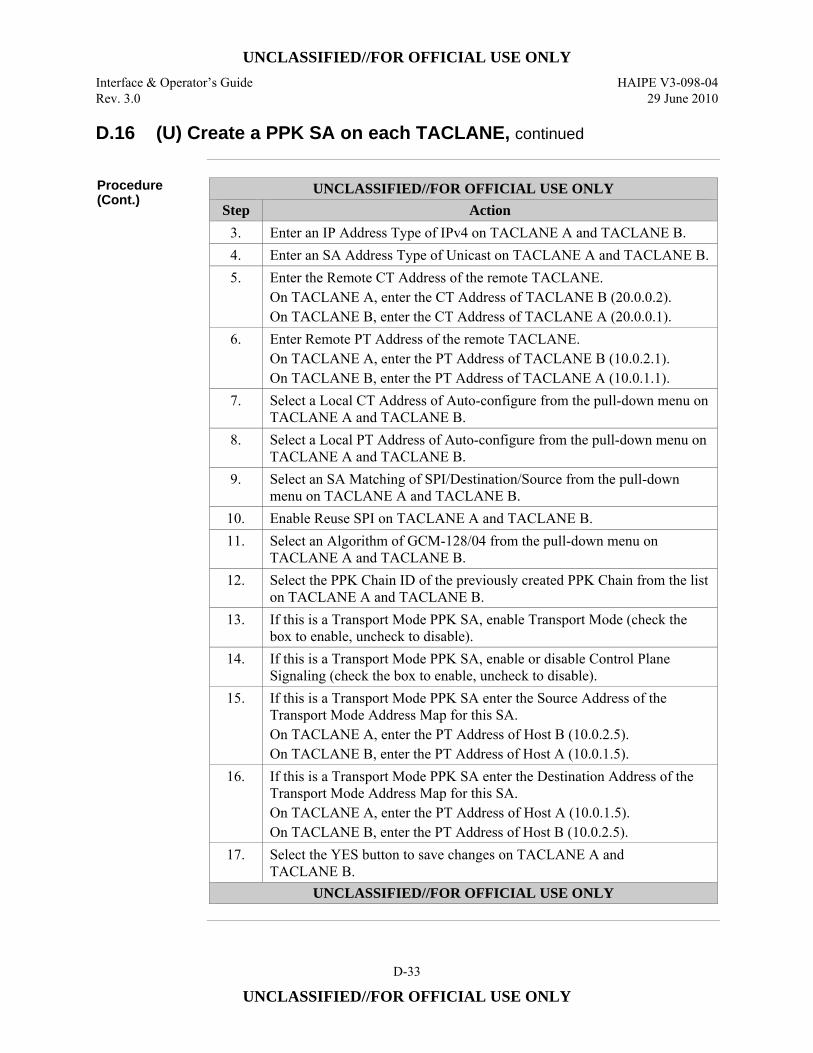
UNCLASSIFIED//FOR OFFICIAL USE ONLY
Interface & Operator’s Guide HAIPE V3-098-04 Rev. 3.0 29 June 2010
D-33
UNCLASSIFIED//FOR OFFICIAL USE ONLY
D.16 (U) Create a PPK SA on each TACLANE, continued
Procedure (Cont.)
UNCLASSIFIED//FOR OFFICIAL USE ONLY Step Action
3. Enter an IP Address Type of IPv4 on TACLANE A and TACLANE B. 4. Enter an SA Address Type of Unicast on TACLANE A and TACLANE B. 5. Enter the Remote CT Address of the remote TACLANE.
On TACLANE A, enter the CT Address of TACLANE B (20.0.0.2). On TACLANE B, enter the CT Address of TACLANE A (20.0.0.1).
6. Enter Remote PT Address of the remote TACLANE. On TACLANE A, enter the PT Address of TACLANE B (10.0.2.1). On TACLANE B, enter the PT Address of TACLANE A (10.0.1.1).
7. Select a Local CT Address of Auto-configure from the pull-down menu on TACLANE A and TACLANE B.
8. Select a Local PT Address of Auto-configure from the pull-down menu on TACLANE A and TACLANE B.
9. Select an SA Matching of SPI/Destination/Source from the pull-down menu on TACLANE A and TACLANE B.
10. Enable Reuse SPI on TACLANE A and TACLANE B. 11. Select an Algorithm of GCM-128/04 from the pull-down menu on
TACLANE A and TACLANE B. 12. Select the PPK Chain ID of the previously created PPK Chain from the list
on TACLANE A and TACLANE B. 13. If this is a Transport Mode PPK SA, enable Transport Mode (check the
box to enable, uncheck to disable). 14. If this is a Transport Mode PPK SA, enable or disable Control Plane
Signaling (check the box to enable, uncheck to disable). 15. If this is a Transport Mode PPK SA enter the Source Address of the
Transport Mode Address Map for this SA. On TACLANE A, enter the PT Address of Host B (10.0.2.5). On TACLANE B, enter the PT Address of Host A (10.0.1.5).
16. If this is a Transport Mode PPK SA enter the Destination Address of the Transport Mode Address Map for this SA. On TACLANE A, enter the PT Address of Host A (10.0.1.5). On TACLANE B, enter the PT Address of Host B (10.0.2.5).
17. Select the YES button to save changes on TACLANE A and TACLANE B.
UNCLASSIFIED//FOR OFFICIAL USE ONLY
UNCLASSIFIED//FOR OFFICIAL USE ONLY
HAIPE V3-098-04 Interface & Operator’s Guide 29 June 2010 Rev. 3.0
D-34
UNCLASSIFIED//FOR OFFICIAL USE ONLY
D.17 (U) Configuring IPv6 Multicast PPK SAs
Introduction (U//FOUO) This is an example of how to configure IPv6 PPK SAs in a TACLANE.
This example details the steps necessary to set up an IPv6 Multicast Suite A PPK SA. The steps are presented in the following sections: • D.18 – (U) Create PT-to-CT Address Mapping for Multicast Control Messages • D.19 – • (U) Configure Multicast Static Routes on each TACLANE • D.20 – (U) Fill Suite A PPK on each TACLANE • D.21 – (U) Create PPK Chain with the Filled PPK on each TACLANE • D.22 – (U) Create a Selector on each TACLANE • D.23 – (U) Create a Rule on each TACLANE • D.24 – (U) Assign PPK to the Multicast Address on each TACLANE
D.18 (U) Create PT-to-CT Address Mapping for Multicast Control
Messages
Introduction (U//FOUO) Create Multicast Address mappings for Multicast Control Messages on
TACLANE A and TACLANE B.
Procedure (U//FOUO) Follow these steps to create entries in the Multicast Address Mapping
Table for Multicast Control Messages on TACLANE A and TACLANE B:
Continued on Next Page
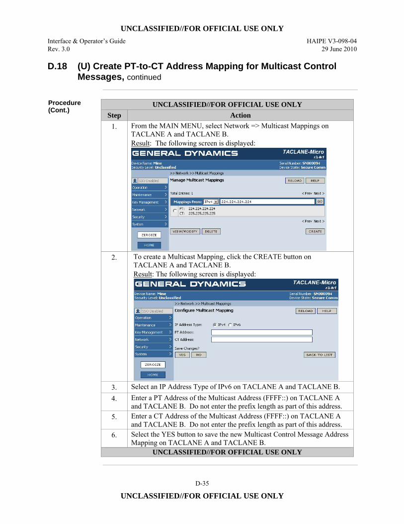
UNCLASSIFIED//FOR OFFICIAL USE ONLY
Interface & Operator’s Guide HAIPE V3-098-04 Rev. 3.0 29 June 2010
D-35
UNCLASSIFIED//FOR OFFICIAL USE ONLY
D.18 (U) Create PT-to-CT Address Mapping for Multicast Control Messages, continued
Procedure (Cont.)
UNCLASSIFIED//FOR OFFICIAL USE ONLY Step Action
1. From the MAIN MENU, select Network => Multicast Mappings on TACLANE A and TACLANE B. Result: The following screen is displayed:
2. To create a Multicast Mapping, click the CREATE button on TACLANE A and TACLANE B. Result: The following screen is displayed:
3. Select an IP Address Type of IPv6 on TACLANE A and TACLANE B. 4. Enter a PT Address of the Multicast Address (FFFF::) on TACLANE A
and TACLANE B. Do not enter the prefix length as part of this address. 5. Enter a CT Address of the Multicast Address (FFFF::) on TACLANE A
and TACLANE B. Do not enter the prefix length as part of this address. 6. Select the YES button to save the new Multicast Control Message Address
Mapping on TACLANE A and TACLANE B. UNCLASSIFIED//FOR OFFICIAL USE ONLY
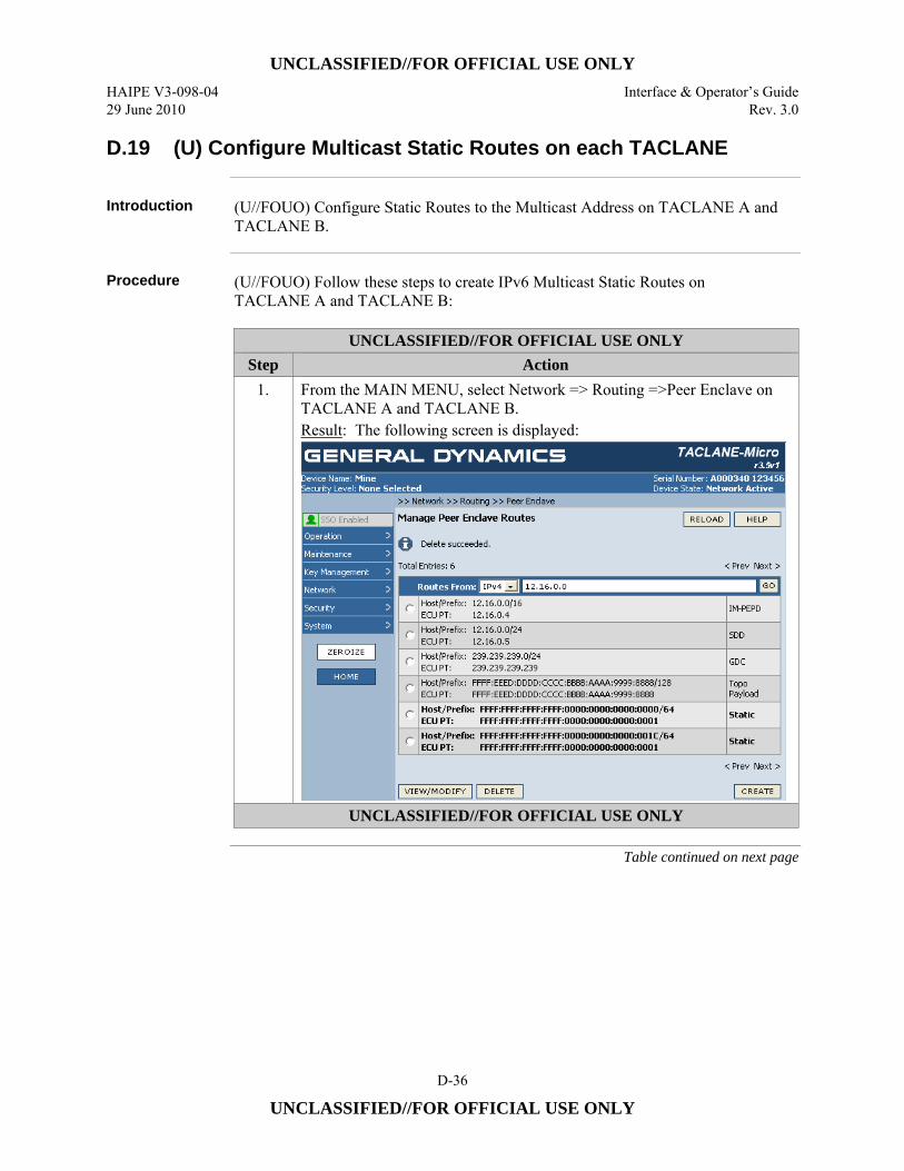
UNCLASSIFIED//FOR OFFICIAL USE ONLY
HAIPE V3-098-04 Interface & Operator’s Guide 29 June 2010 Rev. 3.0
D-36
UNCLASSIFIED//FOR OFFICIAL USE ONLY
D.19 (U) Configure Multicast Static Routes on each TACLANE
Introduction (U//FOUO) Configure Static Routes to the Multicast Address on TACLANE A and
TACLANE B.
Procedure (U//FOUO) Follow these steps to create IPv6 Multicast Static Routes on
TACLANE A and TACLANE B:
UNCLASSIFIED//FOR OFFICIAL USE ONLY Step Action
1. From the MAIN MENU, select Network => Routing =>Peer Enclave on TACLANE A and TACLANE B. Result: The following screen is displayed:
UNCLASSIFIED//FOR OFFICIAL USE ONLY
Table continued on next page
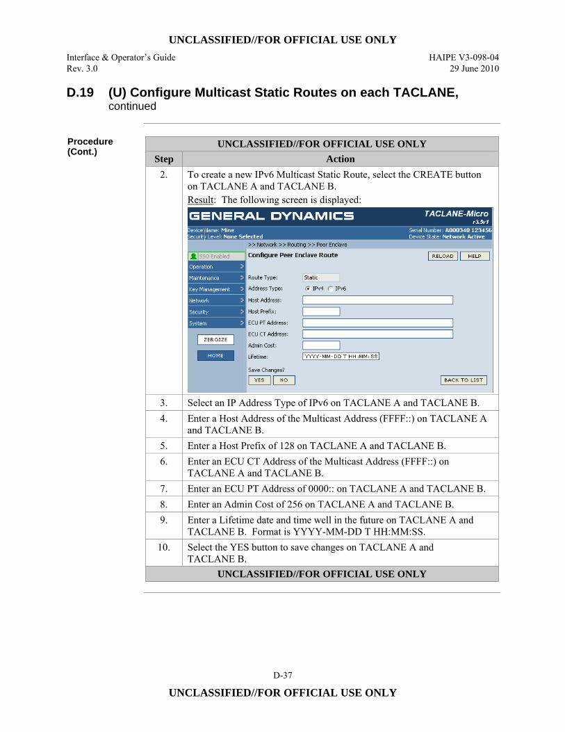
UNCLASSIFIED//FOR OFFICIAL USE ONLY
Interface & Operator’s Guide HAIPE V3-098-04 Rev. 3.0 29 June 2010
D-37
UNCLASSIFIED//FOR OFFICIAL USE ONLY
D.19 (U) Configure Multicast Static Routes on each TACLANE, continued
Procedure (Cont.)
UNCLASSIFIED//FOR OFFICIAL USE ONLY Step Action
2. To create a new IPv6 Multicast Static Route, select the CREATE button on TACLANE A and TACLANE B. Result: The following screen is displayed:
3. Select an IP Address Type of IPv6 on TACLANE A and TACLANE B. 4. Enter a Host Address of the Multicast Address (FFFF::) on TACLANE A
and TACLANE B. 5. Enter a Host Prefix of 128 on TACLANE A and TACLANE B. 6. Enter an ECU CT Address of the Multicast Address (FFFF::) on
TACLANE A and TACLANE B. 7. Enter an ECU PT Address of 0000:: on TACLANE A and TACLANE B. 8. Enter an Admin Cost of 256 on TACLANE A and TACLANE B. 9. Enter a Lifetime date and time well in the future on TACLANE A and
TACLANE B. Format is YYYY-MM-DD T HH:MM:SS. 10. Select the YES button to save changes on TACLANE A and
TACLANE B. UNCLASSIFIED//FOR OFFICIAL USE ONLY
UNCLASSIFIED//FOR OFFICIAL USE ONLY
HAIPE V3-098-04 Interface & Operator’s Guide 29 June 2010 Rev. 3.0
D-38
UNCLASSIFIED//FOR OFFICIAL USE ONLY
D.20 (U) Fill Suite A PPK on each TACLANE
Introduction (U//FOUO) Fill the same Suite A PPK on TACLANE A and TACLANE B.
Notes (U//FOUO) The following notes apply to filling PPKs:
• (U//FOUO) One key or multiple keys can be filled into the TACLANE through one wake-up signal initiated session. There is no operator intervention needed at the TACLANE to fill keys.
Procedure (U//FOUO) Follow these steps to fill the same Suite A PPK on TACLANE A and
TACLANE B:
UNCLASSIFIED//FOR OFFICIAL USE ONLY Step Action
1. Make sure the DTD is configured to initiate a wake-up signal, or equivalent, prior to sending key material to the TACLANE.
2. Connect the DTD to TACLANE A, and fill a Suite A PPK.
3. Connect the DTD to TACLANE B, and fill the same Suite A PPK.
UNCLASSIFIED//FOR OFFICIAL USE ONLY
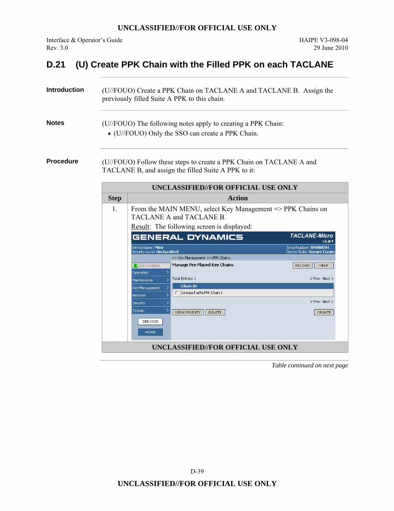
UNCLASSIFIED//FOR OFFICIAL USE ONLY
Interface & Operator’s Guide HAIPE V3-098-04 Rev. 3.0 29 June 2010
D-39
UNCLASSIFIED//FOR OFFICIAL USE ONLY
D.21 (U) Create PPK Chain with the Filled PPK on each TACLANE
Introduction (U//FOUO) Create a PPK Chain on TACLANE A and TACLANE B. Assign the
previously filled Suite A PPK to this chain.
Notes (U//FOUO) The following notes apply to creating a PPK Chain:
• (U//FOUO) Only the SSO can create a PPK Chain.
Procedure (U//FOUO) Follow these steps to create a PPK Chain on TACLANE A and
TACLANE B, and assign the filled Suite A PPK to it:
UNCLASSIFIED//FOR OFFICIAL USE ONLY Step Action
1. From the MAIN MENU, select Key Management => PPK Chains on TACLANE A and TACLANE B. Result: The following screen is displayed:
UNCLASSIFIED//FOR OFFICIAL USE ONLY
Table continued on next page
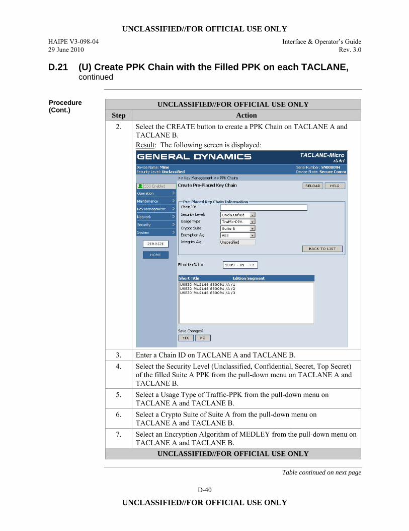
UNCLASSIFIED//FOR OFFICIAL USE ONLY
HAIPE V3-098-04 Interface & Operator’s Guide 29 June 2010 Rev. 3.0
D-40
UNCLASSIFIED//FOR OFFICIAL USE ONLY
D.21 (U) Create PPK Chain with the Filled PPK on each TACLANE, continued
Procedure (Cont.)
UNCLASSIFIED//FOR OFFICIAL USE ONLY Step Action
2. Select the CREATE button to create a PPK Chain on TACLANE A and TACLANE B. Result: The following screen is displayed:
3. Enter a Chain ID on TACLANE A and TACLANE B. 4. Select the Security Level (Unclassified, Confidential, Secret, Top Secret)
of the filled Suite A PPK from the pull-down menu on TACLANE A and TACLANE B.
5. Select a Usage Type of Traffic-PPK from the pull-down menu on TACLANE A and TACLANE B.
6. Select a Crypto Suite of Suite A from the pull-down menu on TACLANE A and TACLANE B.
7. Select an Encryption Algorithm of MEDLEY from the pull-down menu on TACLANE A and TACLANE B.
UNCLASSIFIED//FOR OFFICIAL USE ONLY
Table continued on next page
UNCLASSIFIED//FOR OFFICIAL USE ONLY
Interface & Operator’s Guide HAIPE V3-098-04 Rev. 3.0 29 June 2010
D-41
UNCLASSIFIED//FOR OFFICIAL USE ONLY
D.21 (U) Create PPK Chain with the Filled PPK on each TACLANE, continued
Procedure (Cont.)
UNCLASSIFIED//FOR OFFICIAL USE ONLY Step Action
8. Enter the Effective Date (year and month) on TACLANE A and TACLANE B.
9. Select the previously filled Suite A PPK from the list of unassigned keys on TACLANE A and TACLANE B.
10. Select the YES button to create the chain on TACLANE A and TACLANE B.
UNCLASSIFIED//FOR OFFICIAL USE ONLY
D.22 (U) Create a Selector on each TACLANE
Introduction (U//FOUO) Create a Selector on TACLANE A and TACLANE B to associate with a
CT OUT, Protect with PPK Rule, specifying that the IPv6 traffic being sent to the Multicast Address must be protected using PPK.
Notes (U//FOUO) The following notes apply to creating Selectors:
• Only the SSO can access this command.
Continued on next page
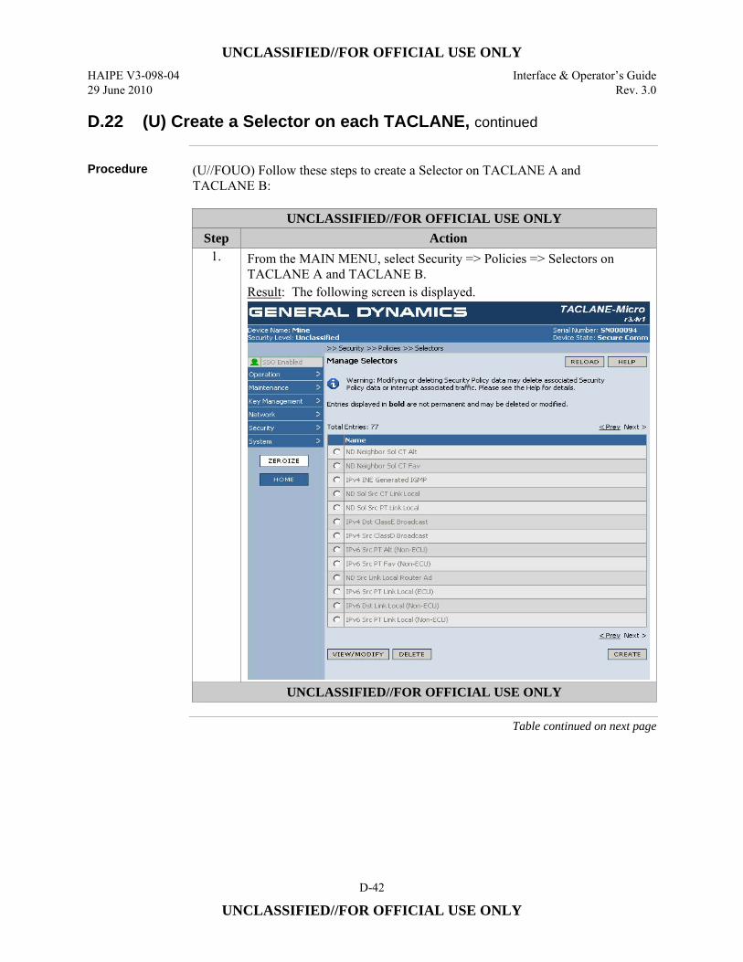
UNCLASSIFIED//FOR OFFICIAL USE ONLY
HAIPE V3-098-04 Interface & Operator’s Guide 29 June 2010 Rev. 3.0
D-42
UNCLASSIFIED//FOR OFFICIAL USE ONLY
D.22 (U) Create a Selector on each TACLANE, continued
Procedure (U//FOUO) Follow these steps to create a Selector on TACLANE A and
TACLANE B:
UNCLASSIFIED//FOR OFFICIAL USE ONLY Step Action
1. From the MAIN MENU, select Security => Policies => Selectors on TACLANE A and TACLANE B. Result: The following screen is displayed.
UNCLASSIFIED//FOR OFFICIAL USE ONLY
Table continued on next page
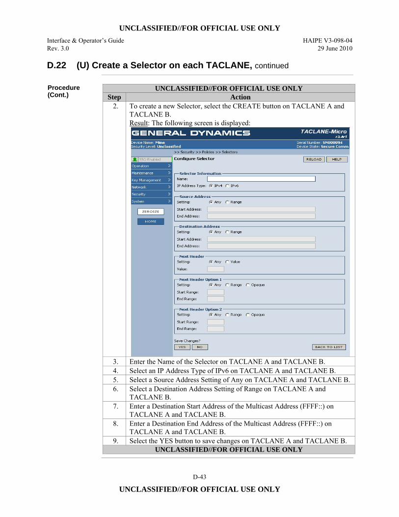
UNCLASSIFIED//FOR OFFICIAL USE ONLY
Interface & Operator’s Guide HAIPE V3-098-04 Rev. 3.0 29 June 2010
D-43
UNCLASSIFIED//FOR OFFICIAL USE ONLY
D.22 (U) Create a Selector on each TACLANE, continued
Procedure (Cont.)
UNCLASSIFIED//FOR OFFICIAL USE ONLY Step Action
2. To create a new Selector, select the CREATE button on TACLANE A and TACLANE B. Result: The following screen is displayed:
3. Enter the Name of the Selector on TACLANE A and TACLANE B. 4. Select an IP Address Type of IPv6 on TACLANE A and TACLANE B. 5. Select a Source Address Setting of Any on TACLANE A and TACLANE B. 6. Select a Destination Address Setting of Range on TACLANE A and
TACLANE B. 7. Enter a Destination Start Address of the Multicast Address (FFFF::) on
TACLANE A and TACLANE B. 8. Enter a Destination End Address of the Multicast Address (FFFF::) on
TACLANE A and TACLANE B. 9. Select the YES button to save changes on TACLANE A and TACLANE B.
UNCLASSIFIED//FOR OFFICIAL USE ONLY
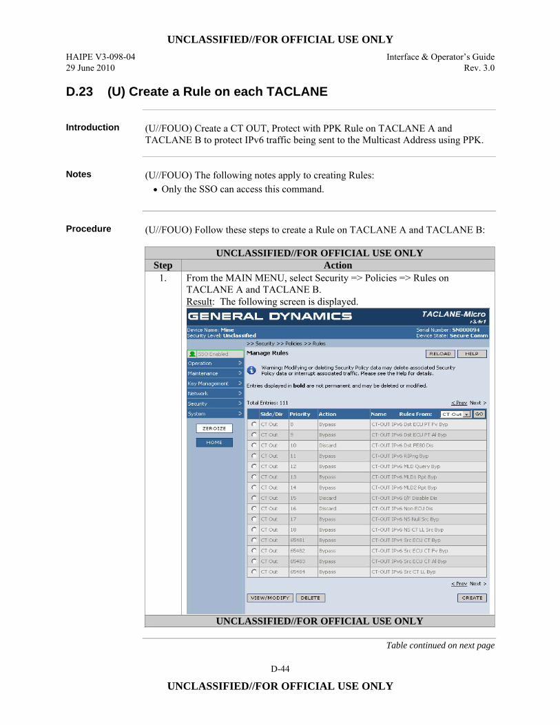
UNCLASSIFIED//FOR OFFICIAL USE ONLY
HAIPE V3-098-04 Interface & Operator’s Guide 29 June 2010 Rev. 3.0
D-44
UNCLASSIFIED//FOR OFFICIAL USE ONLY
D.23 (U) Create a Rule on each TACLANE
Introduction (U//FOUO) Create a CT OUT, Protect with PPK Rule on TACLANE A and
TACLANE B to protect IPv6 traffic being sent to the Multicast Address using PPK.
Notes (U//FOUO) The following notes apply to creating Rules:
• Only the SSO can access this command.
Procedure (U//FOUO) Follow these steps to create a Rule on TACLANE A and TACLANE B:
UNCLASSIFIED//FOR OFFICIAL USE ONLY Step Action
1. From the MAIN MENU, select Security => Policies => Rules on TACLANE A and TACLANE B. Result: The following screen is displayed.
UNCLASSIFIED//FOR OFFICIAL USE ONLY
Table continued on next page

UNCLASSIFIED//FOR OFFICIAL USE ONLY
Interface & Operator’s Guide HAIPE V3-098-04 Rev. 3.0 29 June 2010
D-45
UNCLASSIFIED//FOR OFFICIAL USE ONLY
D.23 (U) Create a Rule on each TACLANE, continued
Procedure (Cont.)
UNCLASSIFIED//FOR OFFICIAL USE ONLY Step Action
2. To create a new Rule, select the CREATE button on TACLANE A and TACLANE B. Result: The following screen is displayed:
3. Enable the Rule on TACLANE A and TACLANE B. 4. Enter the Name of the Rule on TACLANE A and TACLANE B. 5. Enter the Priority of the Rule, from 256 to 65280, on TACLANE A and
TACLANE B. 6. Select a Side/Direction of CT OUT from the pull-down menu on
TACLANE A and TACLANE B. 7. Select the previously created Selector to associate with this Rule from the
scrolled list on TACLANE A and TACLANE B. 8. Select an Action of Protect with PPK from the pull-down menu on
TACLANE A and TACLANE B. 9. Select the previously created PPK Chain ID from the scrolled list on
TACLANE A and TACLANE B. 10. Select the YES button to save changes on TACLANE A and
TACLANE B. UNCLASSIFIED//FOR OFFICIAL USE ONLY
UNCLASSIFIED//FOR OFFICIAL USE ONLY
HAIPE V3-098-04 Interface & Operator’s Guide 29 June 2010 Rev. 3.0
D-46
UNCLASSIFIED//FOR OFFICIAL USE ONLY
D.24 (U) Assign PPK to the Multicast Address on each TACLANE
Introduction (U//FOUO) Create a PPK SA on TACLANE A and TACLANE B to protect IPv6
traffic being sent to the Multicast Address using PPK. (U//FOUO) The steps listed below include those necessary to create a Transport Mode PPK SA.
Notes (U//FOUO) The following notes apply to creating PPK SAs:
• (U//FOUO) Only the SSO can access this command. • (U//FOUO) Transport Mode PPK SAs cannot be created if FPL is enabled. • (U//FOUO) Transport Mode PPK SAs cannot be created with Legacy PPK
Chains • (U//FOUO) If Control Plane Signaling is not enabled for a Transport Mode PPK
SA then the Transport Mode PPK SA cannot be created unless PPK PDUN Transmit is disabled and the PPK PHRD Rate is disabled.
• (U//FOUO) A multicast Transport Mode PPK SA must be associated with a Transport Mode Address map that contains a multicast destination address.
• (U//FOUO) A unicast Transport Mode PPK SA must be associated with a Transport Mode Address map that contains a unicast destination address.
Continued on Next Page
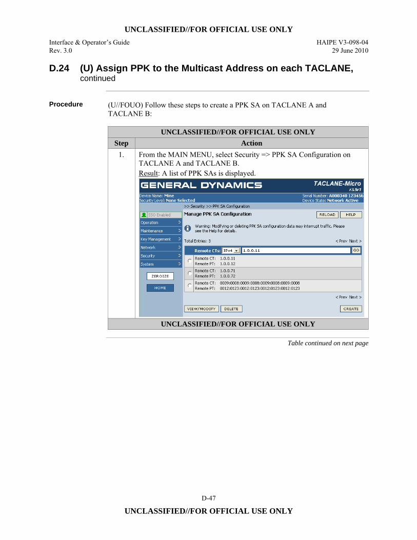
UNCLASSIFIED//FOR OFFICIAL USE ONLY
Interface & Operator’s Guide HAIPE V3-098-04 Rev. 3.0 29 June 2010
D-47
UNCLASSIFIED//FOR OFFICIAL USE ONLY
D.24 (U) Assign PPK to the Multicast Address on each TACLANE, continued
Procedure (U//FOUO) Follow these steps to create a PPK SA on TACLANE A and
TACLANE B:
UNCLASSIFIED//FOR OFFICIAL USE ONLY Step Action
1. From the MAIN MENU, select Security => PPK SA Configuration on TACLANE A and TACLANE B. Result: A list of PPK SAs is displayed.
UNCLASSIFIED//FOR OFFICIAL USE ONLY
Table continued on next page
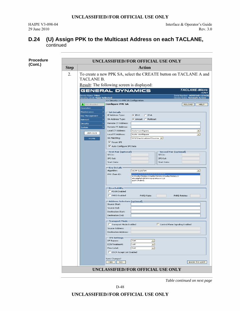
UNCLASSIFIED//FOR OFFICIAL USE ONLY
HAIPE V3-098-04 Interface & Operator’s Guide 29 June 2010 Rev. 3.0
D-48
UNCLASSIFIED//FOR OFFICIAL USE ONLY
D.24 (U) Assign PPK to the Multicast Address on each TACLANE, continued
Procedure (Cont.)
UNCLASSIFIED//FOR OFFICIAL USE ONLY Step Action
2. To create a new PPK SA, select the CREATE button on TACLANE A and TACLANE B. Result: The following screen is displayed:
UNCLASSIFIED//FOR OFFICIAL USE ONLY
Table continued on next page
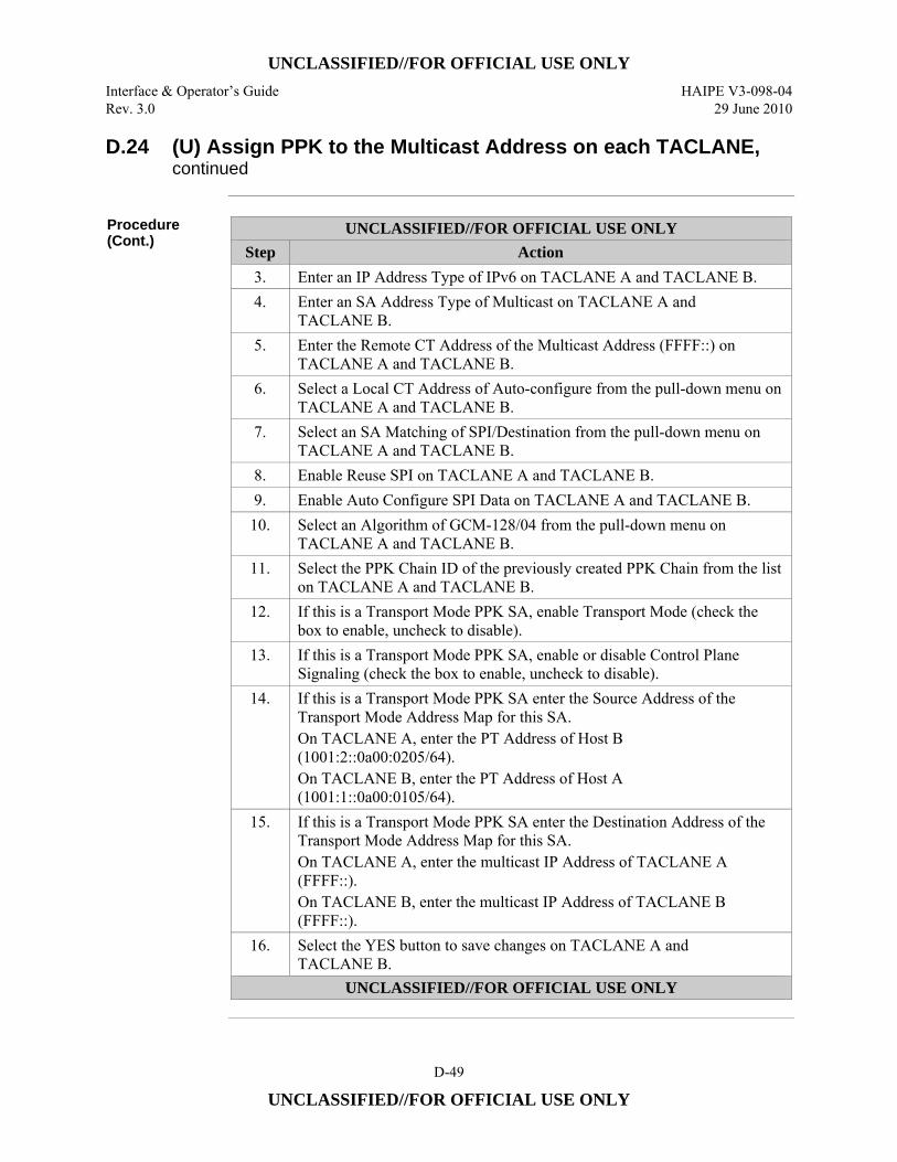
UNCLASSIFIED//FOR OFFICIAL USE ONLY
Interface & Operator’s Guide HAIPE V3-098-04 Rev. 3.0 29 June 2010
D-49
UNCLASSIFIED//FOR OFFICIAL USE ONLY
D.24 (U) Assign PPK to the Multicast Address on each TACLANE, continued
Procedure (Cont.)
UNCLASSIFIED//FOR OFFICIAL USE ONLY Step Action
3. Enter an IP Address Type of IPv6 on TACLANE A and TACLANE B. 4. Enter an SA Address Type of Multicast on TACLANE A and
TACLANE B. 5. Enter the Remote CT Address of the Multicast Address (FFFF::) on
TACLANE A and TACLANE B. 6. Select a Local CT Address of Auto-configure from the pull-down menu on
TACLANE A and TACLANE B. 7. Select an SA Matching of SPI/Destination from the pull-down menu on
TACLANE A and TACLANE B. 8. Enable Reuse SPI on TACLANE A and TACLANE B. 9. Enable Auto Configure SPI Data on TACLANE A and TACLANE B.
10. Select an Algorithm of GCM-128/04 from the pull-down menu on TACLANE A and TACLANE B.
11. Select the PPK Chain ID of the previously created PPK Chain from the list on TACLANE A and TACLANE B.
12. If this is a Transport Mode PPK SA, enable Transport Mode (check the box to enable, uncheck to disable).
13. If this is a Transport Mode PPK SA, enable or disable Control Plane Signaling (check the box to enable, uncheck to disable).
14. If this is a Transport Mode PPK SA enter the Source Address of the Transport Mode Address Map for this SA. On TACLANE A, enter the PT Address of Host B (1001:2::0a00:0205/64). On TACLANE B, enter the PT Address of Host A (1001:1::0a00:0105/64).
15. If this is a Transport Mode PPK SA enter the Destination Address of the Transport Mode Address Map for this SA. On TACLANE A, enter the multicast IP Address of TACLANE A (FFFF::). On TACLANE B, enter the multicast IP Address of TACLANE B (FFFF::).
16. Select the YES button to save changes on TACLANE A and TACLANE B.
UNCLASSIFIED//FOR OFFICIAL USE ONLY
UNCLASSIFIED//FOR OFFICIAL USE ONLY
HAIPE V3-098-04 Interface & Operator’s Guide 29 June 2010 Rev. 3.0
D-50
UNCLASSIFIED//FOR OFFICIAL USE ONLY
D.25 (U) Configuring IPv4 FIREFLY SAs
Introduction (U//FOUO) This is an example of how to configure IPv4 FIREFLY SAs in a
TACLANE. This example details the steps necessary to set up an IPv4 AES EFF FIREFLY SA. The steps are detailed in the following sections: • D.26 – (U) Fill AES EFF FIREFLY Vector Set on each TACLANE • D.27 – (U) Create a Selector on each TACLANE (Optional) • D.28 – (U) Create a FIREFLY SA Template on each TACLANE • D.29 – (U) Create Rules on each TACLANE
D.26 (U) Fill AES EFF FIREFLY Vector Set on each TACLANE
Introduction (U//FOUO) Fill compatible AES EFF FIREFLY Vector Sets on TACLANE A and
TACLANE B.
Notes (U//FOUO) The following notes apply to filling FIREFLY Vector Sets:
• (U//FOUO) One key or multiple keys can be filled into the TACLANE through one wake-up signal initiated session. There is no operator intervention needed at the TACLANE to fill keys.
Procedure (U//FOUO) Follow these steps to fill compatible AES EFF FIREFLY Vector Sets on
TACLANE A and TACLANE B:
UNCLASSIFIED//FOR OFFICIAL USE ONLY Step Action
1. Make sure the DTD is configured to initiate a wake-up signal, or equivalent, prior to sending key material to the TACLANE.
2. Connect the DTD to TACLANE A, and fill an AES EFF FIREFLY Vector Set.
3. Connect the DTD to TACLANE B, and fill a compatible AES EFF FIREFLY Vector Set.
UNCLASSIFIED//FOR OFFICIAL USE ONLY
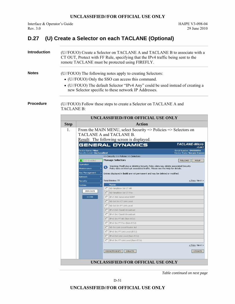
UNCLASSIFIED//FOR OFFICIAL USE ONLY
Interface & Operator’s Guide HAIPE V3-098-04 Rev. 3.0 29 June 2010
D-51
UNCLASSIFIED//FOR OFFICIAL USE ONLY
D.27 (U) Create a Selector on each TACLANE (Optional)
Introduction (U//FOUO) Create a Selector on TACLANE A and TACLANE B to associate with a CT OUT, Protect with FF Rule, specifying that the IPv4 traffic being sent to the remote TACLANE must be protected using FIREFLY.
Notes (U//FOUO) The following notes apply to creating Selectors: • (U//FOUO) Only the SSO can access this command. • (U//FOUO) The default Selector “IPv4 Any” could be used instead of creating a
new Selector specific to these network IP Addresses.
Procedure (U//FOUO) Follow these steps to create a Selector on TACLANE A and
TACLANE B:
UNCLASSIFIED//FOR OFFICIAL USE ONLY Step Action
1. From the MAIN MENU, select Security => Policies => Selectors on TACLANE A and TACLANE B. Result: The following screen is displayed.
UNCLASSIFIED//FOR OFFICIAL USE ONLY
Table continued on next page

UNCLASSIFIED//FOR OFFICIAL USE ONLY
HAIPE V3-098-04 Interface & Operator’s Guide 29 June 2010 Rev. 3.0
D-52
UNCLASSIFIED//FOR OFFICIAL USE ONLY
D.27 (U) Create a Selector on each TACLANE (Optional), continued
Procedure (Cont.)
UNCLASSIFIED//FOR OFFICIAL USE ONLY Step Action
2. To create a new Selector, select the CREATE button on TACLANE A and TACLANE B. Result: The following screen is displayed:
3. Enter the Name of the Selector on TACLANE A and TACLANE B. 4. Select an IP Address Type of IPv4 on TACLANE A and TACLANE B. 5. Select a Source Address Setting of Any on TACLANE A and
TACLANE B. UNCLASSIFIED//FOR OFFICIAL USE ONLY
Table continued on next page
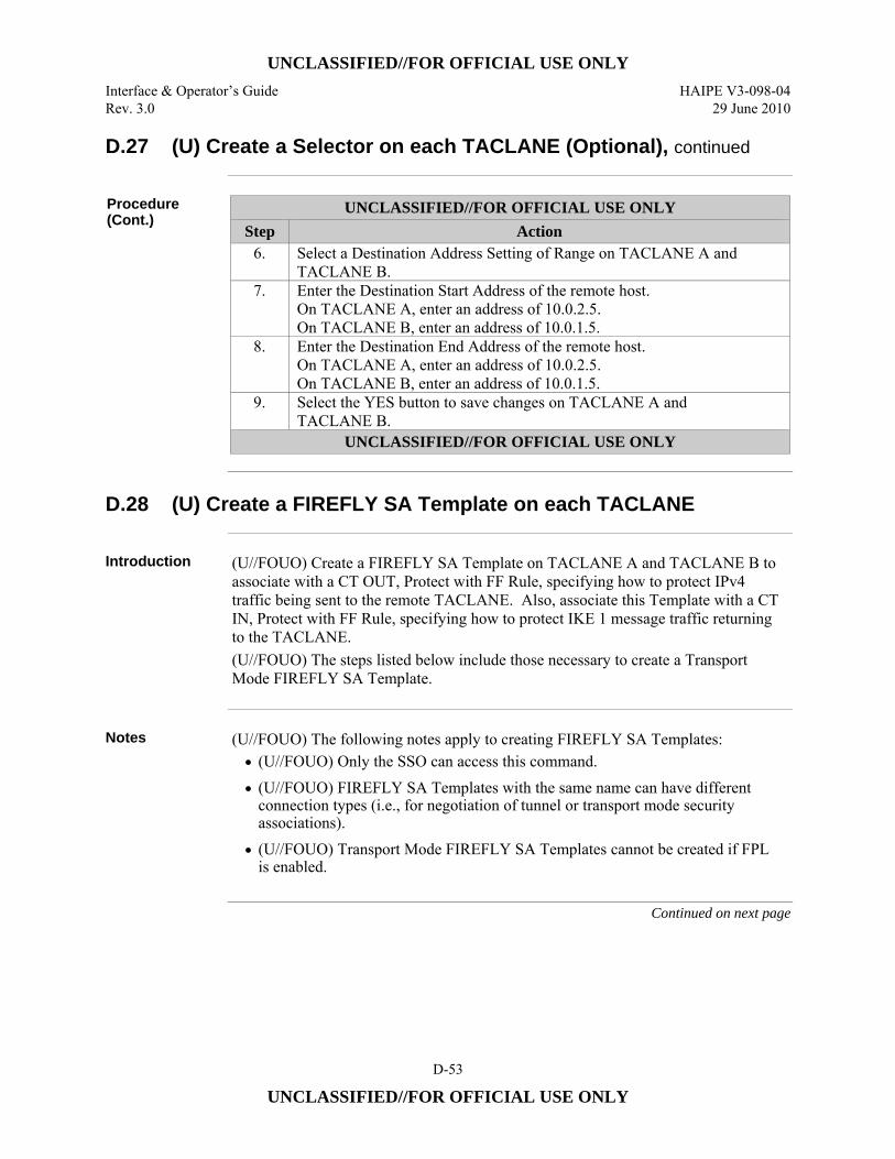
UNCLASSIFIED//FOR OFFICIAL USE ONLY
Interface & Operator’s Guide HAIPE V3-098-04 Rev. 3.0 29 June 2010
D-53
UNCLASSIFIED//FOR OFFICIAL USE ONLY
D.27 (U) Create a Selector on each TACLANE (Optional), continued
Procedure (Cont.)
UNCLASSIFIED//FOR OFFICIAL USE ONLY Step Action
6. Select a Destination Address Setting of Range on TACLANE A and TACLANE B.
7. Enter the Destination Start Address of the remote host. On TACLANE A, enter an address of 10.0.2.5. On TACLANE B, enter an address of 10.0.1.5.
8. Enter the Destination End Address of the remote host. On TACLANE A, enter an address of 10.0.2.5. On TACLANE B, enter an address of 10.0.1.5.
9. Select the YES button to save changes on TACLANE A and TACLANE B.
UNCLASSIFIED//FOR OFFICIAL USE ONLY
D.28 (U) Create a FIREFLY SA Template on each TACLANE
Introduction (U//FOUO) Create a FIREFLY SA Template on TACLANE A and TACLANE B to
associate with a CT OUT, Protect with FF Rule, specifying how to protect IPv4 traffic being sent to the remote TACLANE. Also, associate this Template with a CT IN, Protect with FF Rule, specifying how to protect IKE 1 message traffic returning to the TACLANE. (U//FOUO) The steps listed below include those necessary to create a Transport Mode FIREFLY SA Template.
Notes (U//FOUO) The following notes apply to creating FIREFLY SA Templates:
• (U//FOUO) Only the SSO can access this command. • (U//FOUO) FIREFLY SA Templates with the same name can have different
connection types (i.e., for negotiation of tunnel or transport mode security associations).
• (U//FOUO) Transport Mode FIREFLY SA Templates cannot be created if FPL is enabled.
Continued on next page
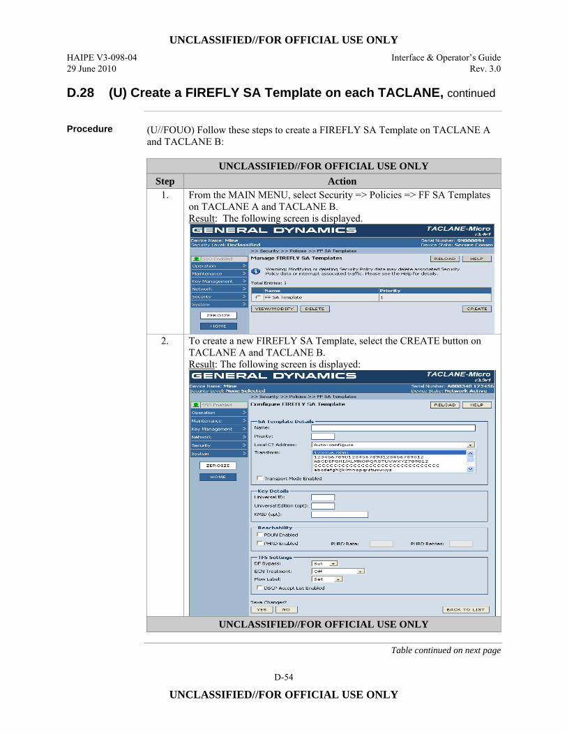
UNCLASSIFIED//FOR OFFICIAL USE ONLY
HAIPE V3-098-04 Interface & Operator’s Guide 29 June 2010 Rev. 3.0
D-54
UNCLASSIFIED//FOR OFFICIAL USE ONLY
D.28 (U) Create a FIREFLY SA Template on each TACLANE, continued
Procedure (U//FOUO) Follow these steps to create a FIREFLY SA Template on TACLANE A
and TACLANE B:
UNCLASSIFIED//FOR OFFICIAL USE ONLY Step Action
1. From the MAIN MENU, select Security => Policies => FF SA Templates on TACLANE A and TACLANE B. Result: The following screen is displayed.
2. To create a new FIREFLY SA Template, select the CREATE button on TACLANE A and TACLANE B. Result: The following screen is displayed:
UNCLASSIFIED//FOR OFFICIAL USE ONLY
Table continued on next page
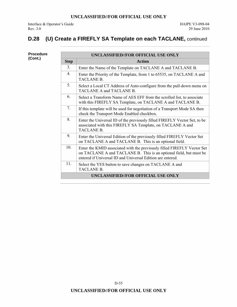
UNCLASSIFIED//FOR OFFICIAL USE ONLY
Interface & Operator’s Guide HAIPE V3-098-04 Rev. 3.0 29 June 2010
D-55
UNCLASSIFIED//FOR OFFICIAL USE ONLY
D.28 (U) Create a FIREFLY SA Template on each TACLANE, continued
Procedure (Cont.)
UNCLASSIFIED//FOR OFFICIAL USE ONLY Step Action
3. Enter the Name of the Template on TACLANE A and TACLANE B. 4. Enter the Priority of the Template, from 1 to 65535, on TACLANE A and
TACLANE B. 5. Select a Local CT Address of Auto-configure from the pull-down menu on
TACLANE A and TACLANE B. 6. Select a Transform Name of AES EFF from the scrolled list, to associate
with this FIREFLY SA Template, on TACLANE A and TACLANE B. 7. If this template will be used for negotiation of a Transport Mode SA then
check the Transport Mode Enabled checkbox. 8. Enter the Universal ID of the previously filled FIREFLY Vector Set, to be
associated with this FIREFLY SA Template, on TACLANE A and TACLANE B.
9. Enter the Universal Edition of the previously filled FIREFLY Vector Set on TACLANE A and TACLANE B. This is an optional field.
10. Enter the KMID associated with the previously filled FIREFLY Vector Set on TACLANE A and TACLANE B. This is an optional field, but must be entered if Universal ID and Universal Edition are entered.
11. Select the YES button to save changes on TACLANE A and TACLANE B.
UNCLASSIFIED//FOR OFFICIAL USE ONLY
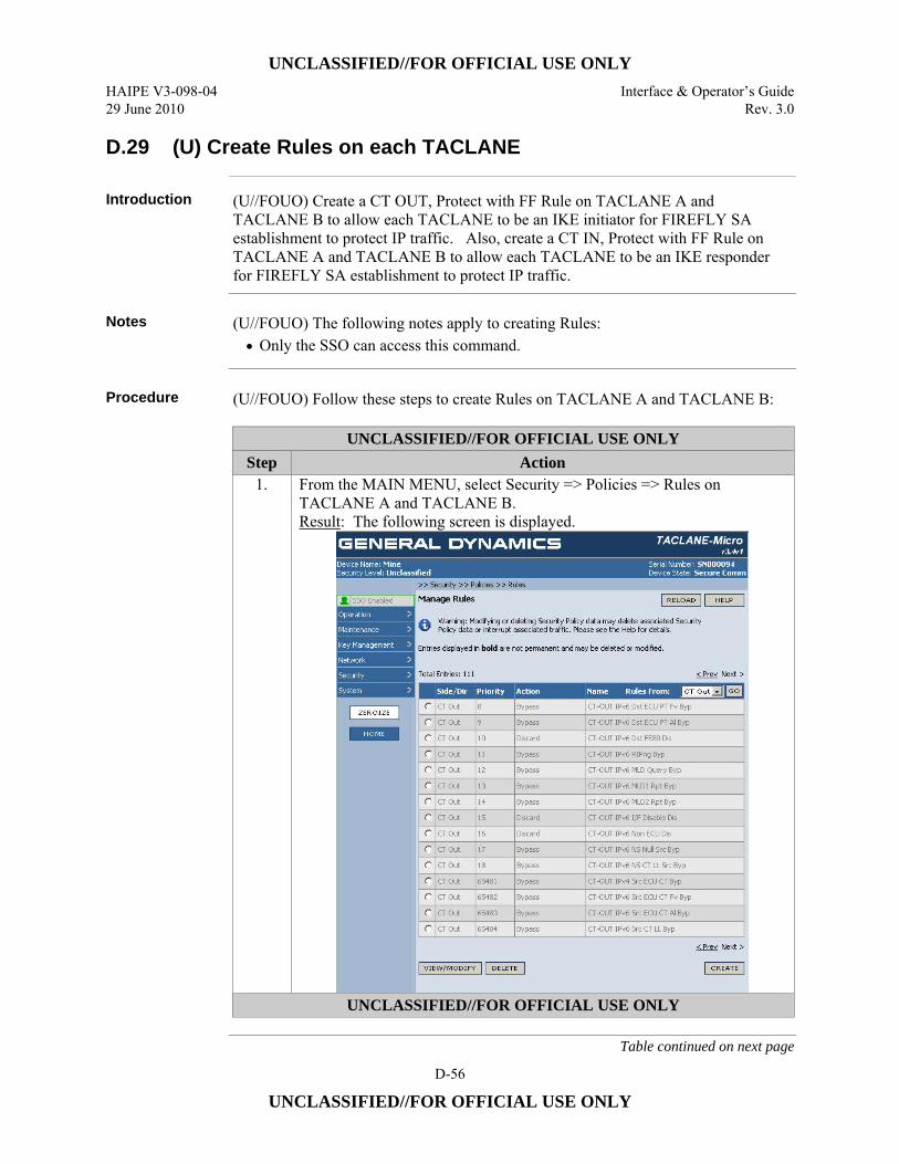
UNCLASSIFIED//FOR OFFICIAL USE ONLY
HAIPE V3-098-04 Interface & Operator’s Guide 29 June 2010 Rev. 3.0
D-56
UNCLASSIFIED//FOR OFFICIAL USE ONLY
D.29 (U) Create Rules on each TACLANE
Introduction (U//FOUO) Create a CT OUT, Protect with FF Rule on TACLANE A and TACLANE B to allow each TACLANE to be an IKE initiator for FIREFLY SA establishment to protect IP traffic. Also, create a CT IN, Protect with FF Rule on TACLANE A and TACLANE B to allow each TACLANE to be an IKE responder for FIREFLY SA establishment to protect IP traffic.
Notes (U//FOUO) The following notes apply to creating Rules:
• Only the SSO can access this command.
Procedure (U//FOUO) Follow these steps to create Rules on TACLANE A and TACLANE B:
UNCLASSIFIED//FOR OFFICIAL USE ONLY Step Action
1. From the MAIN MENU, select Security => Policies => Rules on TACLANE A and TACLANE B. Result: The following screen is displayed.
UNCLASSIFIED//FOR OFFICIAL USE ONLY
Table continued on next page

UNCLASSIFIED//FOR OFFICIAL USE ONLY
Interface & Operator’s Guide HAIPE V3-098-04 Rev. 3.0 29 June 2010
D-57
UNCLASSIFIED//FOR OFFICIAL USE ONLY
D.29 (U) Create Rules on each TACLANE, continued
Procedure (Cont.)
UNCLASSIFIED//FOR OFFICIAL USE ONLY Step Action
2. To create a new Rule, select the CREATE button on TACLANE A and TACLANE B. Result: The following screen is displayed:
3. Enable the Rule on TACLANE A and TACLANE B. 4. Enter the Name of the Rule on TACLANE A and TACLANE B. 5. Enter the Priority of the Rule, from 256 to 65280, on TACLANE A and
TACLANE B. 6. Select a Side/Direction of CT OUT from the pull-down menu on
TACLANE A and TACLANE B. 7. Select the previously created Selector to associate with this Rule from the
scrolled list on TACLANE A and TACLANE B. 8. Select an Action of Protect with FF from the pull-down menu on
TACLANE A and TACLANE B. 9. Select the previously created FIREFLY SA Template from the scrolled list
on TACLANE A and TACLANE B. 10. Select the YES button to save changes on TACLANE A and
TACLANE B. 11. To create a second new Rule, select the CREATE button.
UNCLASSIFIED//FOR OFFICIAL USE ONLY
Table continued on next page
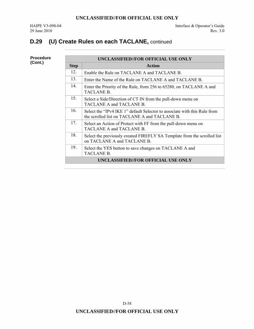
UNCLASSIFIED//FOR OFFICIAL USE ONLY
HAIPE V3-098-04 Interface & Operator’s Guide 29 June 2010 Rev. 3.0
D-58
UNCLASSIFIED//FOR OFFICIAL USE ONLY
D.29 (U) Create Rules on each TACLANE, continued
Procedure (Cont.)
UNCLASSIFIED//FOR OFFICIAL USE ONLY Step Action 12. Enable the Rule on TACLANE A and TACLANE B. 13. Enter the Name of the Rule on TACLANE A and TACLANE B. 14. Enter the Priority of the Rule, from 256 to 65280, on TACLANE A and
TACLANE B. 15. Select a Side/Direction of CT IN from the pull-down menu on
TACLANE A and TACLANE B. 16. Select the “IPv4 IKE 1” default Selector to associate with this Rule from
the scrolled list on TACLANE A and TACLANE B. 17. Select an Action of Protect with FF from the pull-down menu on
TACLANE A and TACLANE B. 18. Select the previously created FIREFLY SA Template from the scrolled list
on TACLANE A and TACLANE B. 19. Select the YES button to save changes on TACLANE A and
TACLANE B. UNCLASSIFIED//FOR OFFICIAL USE ONLY
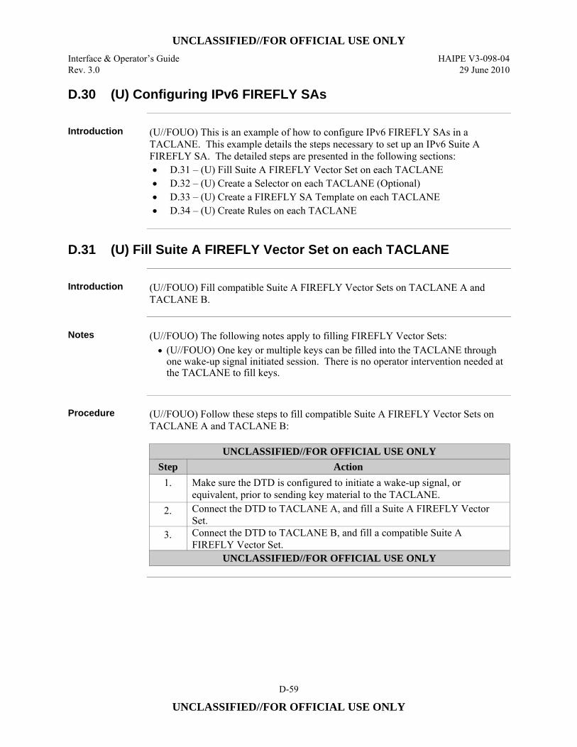
UNCLASSIFIED//FOR OFFICIAL USE ONLY
Interface & Operator’s Guide HAIPE V3-098-04 Rev. 3.0 29 June 2010
D-59
UNCLASSIFIED//FOR OFFICIAL USE ONLY
D.30 (U) Configuring IPv6 FIREFLY SAs
Introduction (U//FOUO) This is an example of how to configure IPv6 FIREFLY SAs in a
TACLANE. This example details the steps necessary to set up an IPv6 Suite A FIREFLY SA. The detailed steps are presented in the following sections: • D.31 – (U) Fill Suite A FIREFLY Vector Set on each TACLANE • D.32 – (U) Create a Selector on each TACLANE (Optional) • D.33 – (U) Create a FIREFLY SA Template on each TACLANE • D.34 – (U) Create Rules on each TACLANE
D.31 (U) Fill Suite A FIREFLY Vector Set on each TACLANE
Introduction (U//FOUO) Fill compatible Suite A FIREFLY Vector Sets on TACLANE A and
TACLANE B.
Notes (U//FOUO) The following notes apply to filling FIREFLY Vector Sets:
• (U//FOUO) One key or multiple keys can be filled into the TACLANE through one wake-up signal initiated session. There is no operator intervention needed at the TACLANE to fill keys.
Procedure (U//FOUO) Follow these steps to fill compatible Suite A FIREFLY Vector Sets on
TACLANE A and TACLANE B:
UNCLASSIFIED//FOR OFFICIAL USE ONLY Step Action
1. Make sure the DTD is configured to initiate a wake-up signal, or equivalent, prior to sending key material to the TACLANE.
2. Connect the DTD to TACLANE A, and fill a Suite A FIREFLY Vector Set.
3. Connect the DTD to TACLANE B, and fill a compatible Suite A FIREFLY Vector Set.
UNCLASSIFIED//FOR OFFICIAL USE ONLY
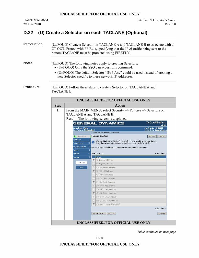
UNCLASSIFIED//FOR OFFICIAL USE ONLY
HAIPE V3-098-04 Interface & Operator’s Guide 29 June 2010 Rev. 3.0
D-60
UNCLASSIFIED//FOR OFFICIAL USE ONLY
D.32 (U) Create a Selector on each TACLANE (Optional)
Introduction (U//FOUO) Create a Selector on TACLANE A and TACLANE B to associate with a CT OUT, Protect with FF Rule, specifying that the IPv6 traffic being sent to the remote TACLANE must be protected using FIREFLY.
Notes (U//FOUO) The following notes apply to creating Selectors:
• (U//FOUO) Only the SSO can access this command. • (U//FOUO) The default Selector “IPv6 Any” could be used instead of creating a
new Selector specific to these network IP Addresses.
Procedure (U//FOUO) Follow these steps to create a Selector on TACLANE A and
TACLANE B:
UNCLASSIFIED//FOR OFFICIAL USE ONLY Step Action
1. From the MAIN MENU, select Security => Policies => Selectors on TACLANE A and TACLANE B. Result: The following screen is displayed.
UNCLASSIFIED//FOR OFFICIAL USE ONLY
Table continued on next page
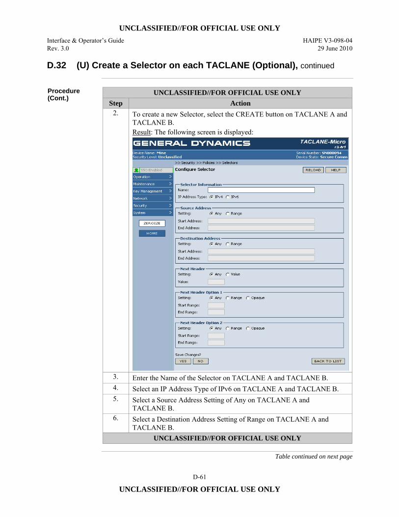
UNCLASSIFIED//FOR OFFICIAL USE ONLY
Interface & Operator’s Guide HAIPE V3-098-04 Rev. 3.0 29 June 2010
D-61
UNCLASSIFIED//FOR OFFICIAL USE ONLY
D.32 (U) Create a Selector on each TACLANE (Optional), continued
Procedure (Cont.)
UNCLASSIFIED//FOR OFFICIAL USE ONLY Step Action
2. To create a new Selector, select the CREATE button on TACLANE A and TACLANE B. Result: The following screen is displayed:
3. Enter the Name of the Selector on TACLANE A and TACLANE B. 4. Select an IP Address Type of IPv6 on TACLANE A and TACLANE B. 5. Select a Source Address Setting of Any on TACLANE A and
TACLANE B. 6. Select a Destination Address Setting of Range on TACLANE A and
TACLANE B. UNCLASSIFIED//FOR OFFICIAL USE ONLY
Table continued on next page
UNCLASSIFIED//FOR OFFICIAL USE ONLY
HAIPE V3-098-04 Interface & Operator’s Guide 29 June 2010 Rev. 3.0
D-62
UNCLASSIFIED//FOR OFFICIAL USE ONLY
D.32 (U) Create a Selector on each TACLANE (Optional), continued
Procedure (Cont.)
UNCLASSIFIED//FOR OFFICIAL USE ONLY Step Action
7. Enter the Destination Start Address of the remote host. On TACLANE A, enter an address of 1001:2::0a00:0205. On TACLANE B, enter an address of 1001:1::0a00:0105.
8. Enter the Destination End Address of the remote host. On TACLANE A, enter an address of 1001:2::0a00:0205. On TACLANE B, enter an address of 1001:1::0a00:0105.
9. Select the YES button to save changes on TACLANE A and TACLANE B.
UNCLASSIFIED//FOR OFFICIAL USE ONLY
D.33 (U) Create a FIREFLY SA Template on each TACLANE
Introduction (U//FOUO) Create a FIREFLY SA Template on TACLANE A and TACLANE B to
associate with a CT OUT, Protect with FF Rule, specifying how to protect IPv6 traffic being sent to the remote TACLANE. Also, associate this Template with a CT IN, Protect with FF Rule, specifying how to protect IKE 1 message traffic returning to the TACLANE. (U//FOUO) The steps listed below include those necessary to create a Transport Mode FIREFLY SA Template.
Notes (U//FOUO) The following notes apply to creating FIREFLY SA Templates:
• (U//FOUO) Only the SSO can access this command. • (U//FOUO) FIREFLY SA Templates with the same name can have different
connection types (i.e., for negotiation of tunnel or transport mode security associations).
• (U//FOUO) Transport Mode FIREFLY SA Templates cannot be created if FPL is enabled.
Continued on next page
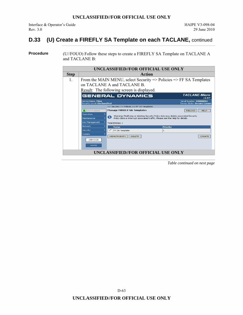
UNCLASSIFIED//FOR OFFICIAL USE ONLY
Interface & Operator’s Guide HAIPE V3-098-04 Rev. 3.0 29 June 2010
D-63
UNCLASSIFIED//FOR OFFICIAL USE ONLY
D.33 (U) Create a FIREFLY SA Template on each TACLANE, continued
Procedure (U//FOUO) Follow these steps to create a FIREFLY SA Template on TACLANE A and TACLANE B:
UNCLASSIFIED//FOR OFFICIAL USE ONLY
Step Action 1. From the MAIN MENU, select Security => Policies => FF SA Templates
on TACLANE A and TACLANE B. Result: The following screen is displayed.
UNCLASSIFIED//FOR OFFICIAL USE ONLY
Table continued on next page
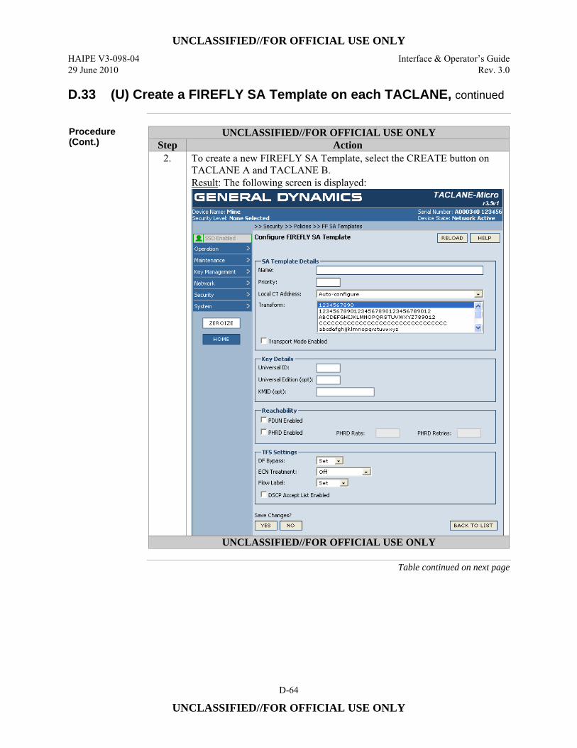
UNCLASSIFIED//FOR OFFICIAL USE ONLY
HAIPE V3-098-04 Interface & Operator’s Guide 29 June 2010 Rev. 3.0
D-64
UNCLASSIFIED//FOR OFFICIAL USE ONLY
D.33 (U) Create a FIREFLY SA Template on each TACLANE, continued
Procedure (Cont.)
UNCLASSIFIED//FOR OFFICIAL USE ONLY Step Action
2. To create a new FIREFLY SA Template, select the CREATE button on TACLANE A and TACLANE B. Result: The following screen is displayed:
UNCLASSIFIED//FOR OFFICIAL USE ONLY
Table continued on next page

UNCLASSIFIED//FOR OFFICIAL USE ONLY
Interface & Operator’s Guide HAIPE V3-098-04 Rev. 3.0 29 June 2010
D-65
UNCLASSIFIED//FOR OFFICIAL USE ONLY
D.33 (U) Create a FIREFLY SA Template on each TACLANE, continued
Procedure (Cont.)
UNCLASSIFIED//FOR OFFICIAL USE ONLY Step Action
3. Enter the Name of the Template on TACLANE A and TACLANE B. 4. Enter the Priority of the Template, from 1 to 65535, on TACLANE A and
TACLANE B. 5. Select a Local CT Address of Auto-configure from the pull-down menu on
TACLANE A and TACLANE B. 6. Select a Transform Name of EFF-SuiteA from the scrolled list, to associate
with this FIREFLY SA Template, on TACLANE A and TACLANE B. 7. If this template will be used for negotiation of a Transport Mode SA then
check the Transport Mode Enabled checkbox. 8. Enter the Universal ID of the previously filled FIREFLY Vector Set, to be
associated with this FIREFLY SA Template, on TACLANE A and TACLANE B.
9. Enter the Universal Edition of the previously filled FIREFLY Vector Set on TACLANE A and TACLANE B. This is an optional field.
10. Enter the KMID associated with the previously filled FIREFLY Vector Set on TACLANE A and TACLANE B. This is an optional field, but must be entered if Universal ID and Universal Edition are entered.
11. Select the YES button to save changes on TACLANE A and TACLANE B.
UNCLASSIFIED//FOR OFFICIAL USE ONLY
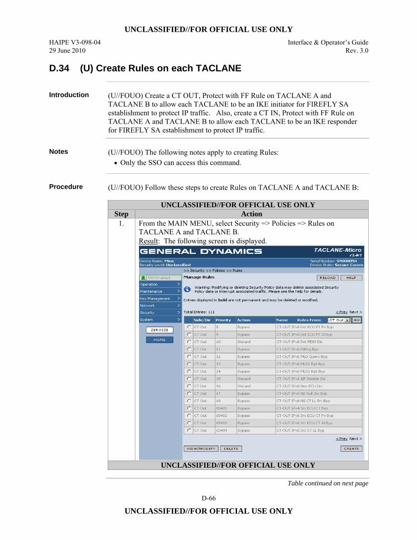
UNCLASSIFIED//FOR OFFICIAL USE ONLY
HAIPE V3-098-04 Interface & Operator’s Guide 29 June 2010 Rev. 3.0
D-66
UNCLASSIFIED//FOR OFFICIAL USE ONLY
D.34 (U) Create Rules on each TACLANE
Introduction (U//FOUO) Create a CT OUT, Protect with FF Rule on TACLANE A and
TACLANE B to allow each TACLANE to be an IKE initiator for FIREFLY SA establishment to protect IP traffic. Also, create a CT IN, Protect with FF Rule on TACLANE A and TACLANE B to allow each TACLANE to be an IKE responder for FIREFLY SA establishment to protect IP traffic.
Notes (U//FOUO) The following notes apply to creating Rules:
• Only the SSO can access this command.
Procedure (U//FOUO) Follow these steps to create Rules on TACLANE A and TACLANE B:
UNCLASSIFIED//FOR OFFICIAL USE ONLY Step Action
1. From the MAIN MENU, select Security => Policies => Rules on TACLANE A and TACLANE B. Result: The following screen is displayed.
UNCLASSIFIED//FOR OFFICIAL USE ONLY
Table continued on next page

UNCLASSIFIED//FOR OFFICIAL USE ONLY
Interface & Operator’s Guide HAIPE V3-098-04 Rev. 3.0 29 June 2010
D-67
UNCLASSIFIED//FOR OFFICIAL USE ONLY
D.34 (U) Create Rules on each TACLANE, continued
Procedure (Cont.)
UNCLASSIFIED//FOR OFFICIAL USE ONLY Step Action
2. To create a new Rule, select the CREATE button on TACLANE A and TACLANE B. Result: The following screen is displayed:
3. Enable the Rule on TACLANE A and TACLANE B. 4. Enter the Name of the Rule on TACLANE A and TACLANE B. 5. Enter the Priority of the Rule, from 256 to 65280, on TACLANE A and
TACLANE B. 6. Select a Side/Direction of CT OUT from the pull-down menu on
TACLANE A and TACLANE B. 7. Select the previously created Selector to associate with this Rule from the
scrolled list on TACLANE A and TACLANE B. 8. Select an Action of Protect with FF from the pull-down menu on
TACLANE A and TACLANE B. 9. Select the previously created FIREFLY SA Template from the scrolled list
on TACLANE A and TACLANE B. 10. Select the YES button to save changes on TACLANE A and
TACLANE B. 11. To create a second new Rule, select the CREATE button.
UNCLASSIFIED//FOR OFFICIAL USE ONLY
Table continued on next page

UNCLASSIFIED//FOR OFFICIAL USE ONLY
HAIPE V3-098-04 Interface & Operator’s Guide 29 June 2010 Rev. 3.0
D-68
UNCLASSIFIED//FOR OFFICIAL USE ONLY
D.34 (U) Create Rules on each TACLANE, continued
Procedure (Cont.)
UNCLASSIFIED//FOR OFFICIAL USE ONLY Step Action 12. Enable the Rule on TACLANE A and TACLANE B. 13. Enter the Name of the Rule on TACLANE A and TACLANE B. 14. Enter the Priority of the Rule, from 256 to 65280, on TACLANE A and
TACLANE B. 15. Select a Side/Direction of CT IN from the pull-down menu on
TACLANE A and TACLANE B. 16. Select the “IPv6 IKE 1” default Selector to associate with this Rule from
the scrolled list on TACLANE A and TACLANE B. 17. Select an Action of Protect with FF from the pull-down menu on
TACLANE A and TACLANE B. 18. Select the previously created FIREFLY SA Template from the scrolled list
on TACLANE A and TACLANE B. 19. Select the YES button to save changes on TACLANE A and
TACLANE B. UNCLASSIFIED//FOR OFFICIAL USE ONLY
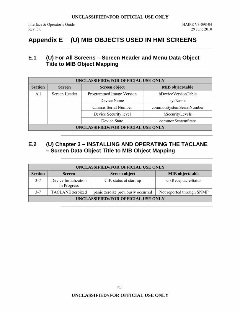
UNCLASSIFIED//FOR OFFICIAL USE ONLY
Interface & Operator’s Guide HAIPE V3-098-04 Rev. 3.0 29 June 2010
E-1
UNCLASSIFIED//FOR OFFICIAL USE ONLY
Appendix E (U) MIB OBJECTS USED IN HMI SCREENS
E.1 (U) For All Screens – Screen Header and Menu Data Object
Title to MIB Object Mapping
UNCLASSIFIED//FOR OFFICIAL USE ONLY
Section Screen Screen object MIB object/table All Screen Header Programmed Image Version hDeviceVersionTable
Device Name sysName Chassis Serial Number commonSystemSerialNumber Device Security level hSecurityLevels
Device State commonSystemState UNCLASSIFIED//FOR OFFICIAL USE ONLY
E.2 (U) Chapter 3 – INSTALLING AND OPERATING THE TACLANE
– Screen Data Object Title to MIB Object Mapping
UNCLASSIFIED//FOR OFFICIAL USE ONLY
Section Screen Screen object MIB object/table 3-7 Device Initialization
In Progress CIK status at start up cikReceptacleStatus
3-7 TACLANE zeroized panic zeroize previously occurred Not reported through SNMP UNCLASSIFIED//FOR OFFICIAL USE ONLY
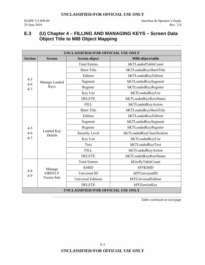
UNCLASSIFIED//FOR OFFICIAL USE ONLY
HAIPE V3-098-04 Interface & Operator’s Guide 29 June 2010 Rev. 3.0
E-2
UNCLASSIFIED//FOR OFFICIAL USE ONLY
E.3 (U) Chapter 4 – FILLING AND MANAGING KEYS – Screen Data Object Title to MIB Object Mapping
UNCLASSIFIED//FOR OFFICIAL USE ONLY
Section Screen Screen object MIB object/table
4-5 4-6 4-7
Manage Loaded Keys
Total Entries hKTLoadedTableCount Short Title hKTLoadedKeyShortTitle
Edition hKTLoadedKeyEdition Segment hKTLoadedKeySegment Register hKTLoadedKeyRegister Key Use hKTLoadedKeyUse DELETE hKTLoadedKeyRowStatus
FILL hKTLoadedKeyAction
4-5 4-6 4-7
Loaded Key Details
Short Title hKTLoadedKeyShortTitle Edition hKTLoadedKeyEdition
Segment hKTLoadedKeySegment Register hKTLoadedKeyRegister
Security Level hKTLoadedKeyClassification Key Use hKTLoadedKeyUse
Text hKTLoadedKeyText FILL hKTLoadedKeyAction
DELETE hKTLoadedKeyRowStatus
4-8 4-9
Manage FIREFLY
Vector Sets
Total Entries hFireflyTableCount KMID hFFKMID
Universal ID hFFUniversalID Universal Editions hFFUniversalEdition
DELETE hFFZeroizeKey UNCLASSIFIED//FOR OFFICIAL USE ONLY
Table continued on next page
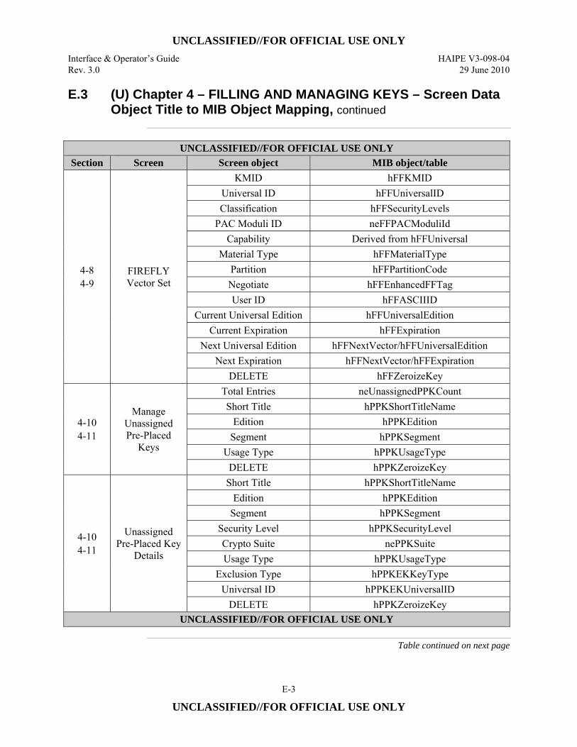
UNCLASSIFIED//FOR OFFICIAL USE ONLY
Interface & Operator’s Guide HAIPE V3-098-04 Rev. 3.0 29 June 2010
E-3
UNCLASSIFIED//FOR OFFICIAL USE ONLY
E.3 (U) Chapter 4 – FILLING AND MANAGING KEYS – Screen Data Object Title to MIB Object Mapping, continued
UNCLASSIFIED//FOR OFFICIAL USE ONLY
Section Screen Screen object MIB object/table
4-8 4-9
FIREFLY Vector Set
KMID hFFKMID Universal ID hFFUniversalID Classification hFFSecurityLevels
PAC Moduli ID neFFPACModuliId Capability Derived from hFFUniversal
Material Type hFFMaterialType Partition hFFPartitionCode Negotiate hFFEnhancedFFTag User ID hFFASCIIID
Current Universal Edition hFFUniversalEdition Current Expiration hFFExpiration
Next Universal Edition hFFNextVector/hFFUniversalEdition Next Expiration hFFNextVector/hFFExpiration
DELETE hFFZeroizeKey
4-10 4-11
Manage Unassigned Pre-Placed
Keys
Total Entries neUnassignedPPKCount Short Title hPPKShortTitleName
Edition hPPKEdition Segment hPPKSegment
Usage Type hPPKUsageType DELETE hPPKZeroizeKey
4-10 4-11
Unassigned Pre-Placed Key
Details
Short Title hPPKShortTitleName Edition hPPKEdition
Segment hPPKSegment Security Level hPPKSecurityLevel Crypto Suite nePPKSuite Usage Type hPPKUsageType
Exclusion Type hPPKEKKeyType Universal ID hPPKEKUniversalID
DELETE hPPKZeroizeKey UNCLASSIFIED//FOR OFFICIAL USE ONLY
Table continued on next page
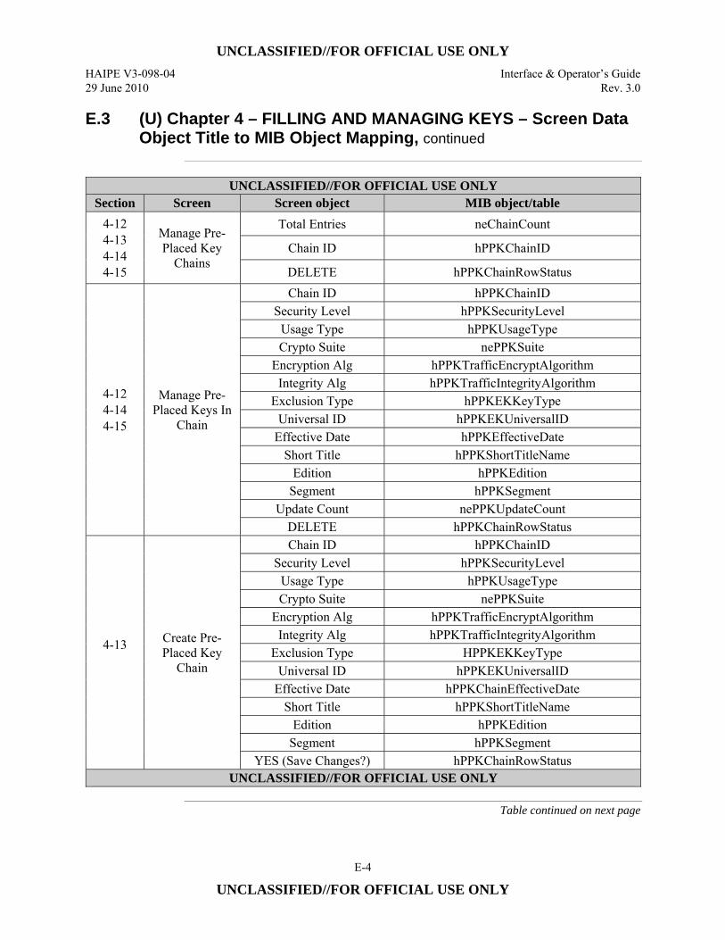
UNCLASSIFIED//FOR OFFICIAL USE ONLY
HAIPE V3-098-04 Interface & Operator’s Guide 29 June 2010 Rev. 3.0
E-4
UNCLASSIFIED//FOR OFFICIAL USE ONLY
E.3 (U) Chapter 4 – FILLING AND MANAGING KEYS – Screen Data Object Title to MIB Object Mapping, continued
UNCLASSIFIED//FOR OFFICIAL USE ONLY
Section Screen Screen object MIB object/table 4-12 4-13 4-14 4-15
Manage Pre-Placed Key
Chains
Total Entries neChainCount
Chain ID hPPKChainID
DELETE hPPKChainRowStatus
4-12 4-14 4-15
Manage Pre-Placed Keys In
Chain
Chain ID hPPKChainID Security Level hPPKSecurityLevel
Usage Type hPPKUsageType Crypto Suite nePPKSuite
Encryption Alg hPPKTrafficEncryptAlgorithm Integrity Alg hPPKTrafficIntegrityAlgorithm
Exclusion Type hPPKEKKeyType Universal ID hPPKEKUniversalID
Effective Date hPPKEffectiveDate Short Title hPPKShortTitleName
Edition hPPKEdition Segment hPPKSegment
Update Count nePPKUpdateCount DELETE hPPKChainRowStatus
4-13
Create Pre-Placed Key
Chain
Chain ID hPPKChainID Security Level hPPKSecurityLevel
Usage Type hPPKUsageType Crypto Suite nePPKSuite
Encryption Alg hPPKTrafficEncryptAlgorithm Integrity Alg hPPKTrafficIntegrityAlgorithm
Exclusion Type HPPKEKKeyType Universal ID hPPKEKUniversalID
Effective Date hPPKChainEffectiveDate Short Title hPPKShortTitleName
Edition hPPKEdition Segment hPPKSegment
YES (Save Changes?) hPPKChainRowStatus UNCLASSIFIED//FOR OFFICIAL USE ONLY
Table continued on next page
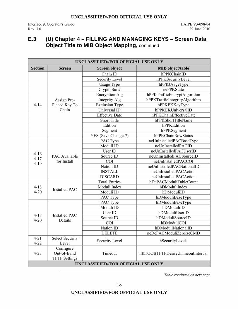
UNCLASSIFIED//FOR OFFICIAL USE ONLY
Interface & Operator’s Guide HAIPE V3-098-04 Rev. 3.0 29 June 2010
E-5
UNCLASSIFIED//FOR OFFICIAL USE ONLY
E.3 (U) Chapter 4 – FILLING AND MANAGING KEYS – Screen Data Object Title to MIB Object Mapping, continued
UNCLASSIFIED//FOR OFFICIAL USE ONLY
Section Screen Screen object MIB object/table
4-14 Assign Pre-
Placed Key To Chain
Chain ID hPPKChainID Security Level hPPKSecurityLevel
Usage Type hPPKUsageType Crypto Suite nePPKSuite
Encryption Alg hPPKTrafficEncryptAlgorithm Integrity Alg hPPKTrafficIntegrityAlgorithm
Exclusion Type hPPKEKKeyType Universal ID hPPKEKUniversalID
Effective Date hPPKChainEffectiveDate Short Title hPPKShortTitleName
Edition hPPKEdition Segment hPPKSegment
YES (Save Changes?) hPPKChainRowStatus
4-16 4-17 4-19
PAC Available for Install
PAC Type neUnInstalledPACBaseType Moduli ID neUnInstalledPACID
User ID neUnInstalledPACUserID Source ID neUnInstalledPACSourceID
COI neUnInstalledPACCOI Nation ID neUnInstalledPACNationalID INSTALL neUnInstalledPACAction DISCARD neUnInstalledPACAction
4-18 4-20 Installed PAC
Total Entries hDePACModuliTableCount Moduli Index hDModuliIndex
Moduli ID hDModuliID PAC Type hDModuliBaseType
4-18 4-20
Installed PAC Details
PAC Type hDModuliBaseType Moduli ID hDModuliID
User ID hDModuliUserID Source ID hDModuliSourceID
COI hDModuliCOI Nation ID hDModuliNationalID DELETE neDePACModuliZeroizeCMD
4-21 4-22
Select Security Level Security Level hSecurityLevels
4-23 Configure
Out-of-Band TFTP Settings
Timeout hKTOOBTFTPDesiredTimeoutInterval
UNCLASSIFIED//FOR OFFICIAL USE ONLY
Table continued on next page
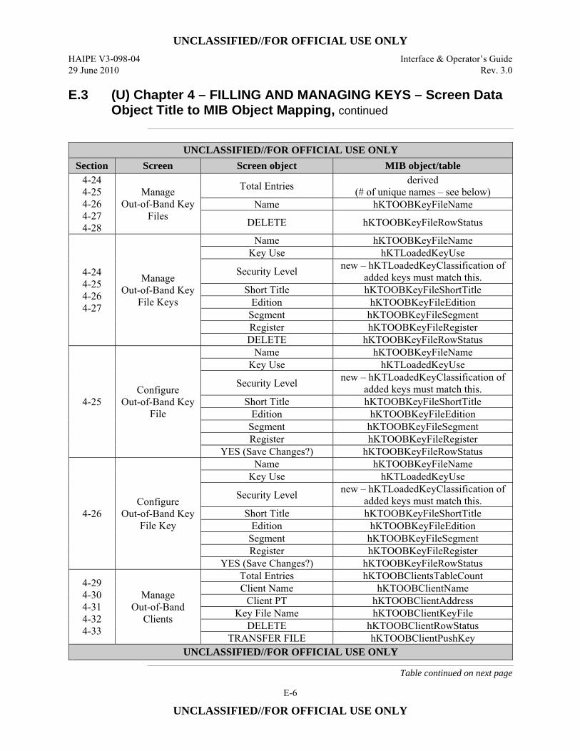
UNCLASSIFIED//FOR OFFICIAL USE ONLY
HAIPE V3-098-04 Interface & Operator’s Guide 29 June 2010 Rev. 3.0
E-6
UNCLASSIFIED//FOR OFFICIAL USE ONLY
E.3 (U) Chapter 4 – FILLING AND MANAGING KEYS – Screen Data Object Title to MIB Object Mapping, continued
UNCLASSIFIED//FOR OFFICIAL USE ONLY
Section Screen Screen object MIB object/table 4-24 4-25 4-26 4-27 4-28
Manage Out-of-Band Key
Files
Total Entries derived (# of unique names – see below)
Name hKTOOBKeyFileName
DELETE hKTOOBKeyFileRowStatus
4-24 4-25 4-26 4-27
Manage Out-of-Band Key
File Keys
Name hKTOOBKeyFileName Key Use hKTLoadedKeyUse
Security Level new – hKTLoadedKeyClassification of added keys must match this.
Short Title hKTOOBKeyFileShortTitle Edition hKTOOBKeyFileEdition
Segment hKTOOBKeyFileSegment Register hKTOOBKeyFileRegister DELETE hKTOOBKeyFileRowStatus
4-25 Configure
Out-of-Band Key File
Name hKTOOBKeyFileName Key Use hKTLoadedKeyUse
Security Level new – hKTLoadedKeyClassification of added keys must match this.
Short Title hKTOOBKeyFileShortTitle Edition hKTOOBKeyFileEdition
Segment hKTOOBKeyFileSegment Register hKTOOBKeyFileRegister
YES (Save Changes?) hKTOOBKeyFileRowStatus
4-26 Configure
Out-of-Band Key File Key
Name hKTOOBKeyFileName Key Use hKTLoadedKeyUse
Security Level new – hKTLoadedKeyClassification of added keys must match this.
Short Title hKTOOBKeyFileShortTitle Edition hKTOOBKeyFileEdition
Segment hKTOOBKeyFileSegment Register hKTOOBKeyFileRegister
YES (Save Changes?) hKTOOBKeyFileRowStatus
4-29 4-30 4-31 4-32 4-33
Manage Out-of-Band
Clients
Total Entries hKTOOBClientsTableCount Client Name hKTOOBClientName
Client PT hKTOOBClientAddress Key File Name hKTOOBClientKeyFile
DELETE hKTOOBClientRowStatus TRANSFER FILE hKTOOBClientPushKey
UNCLASSIFIED//FOR OFFICIAL USE ONLY
Table continued on next page
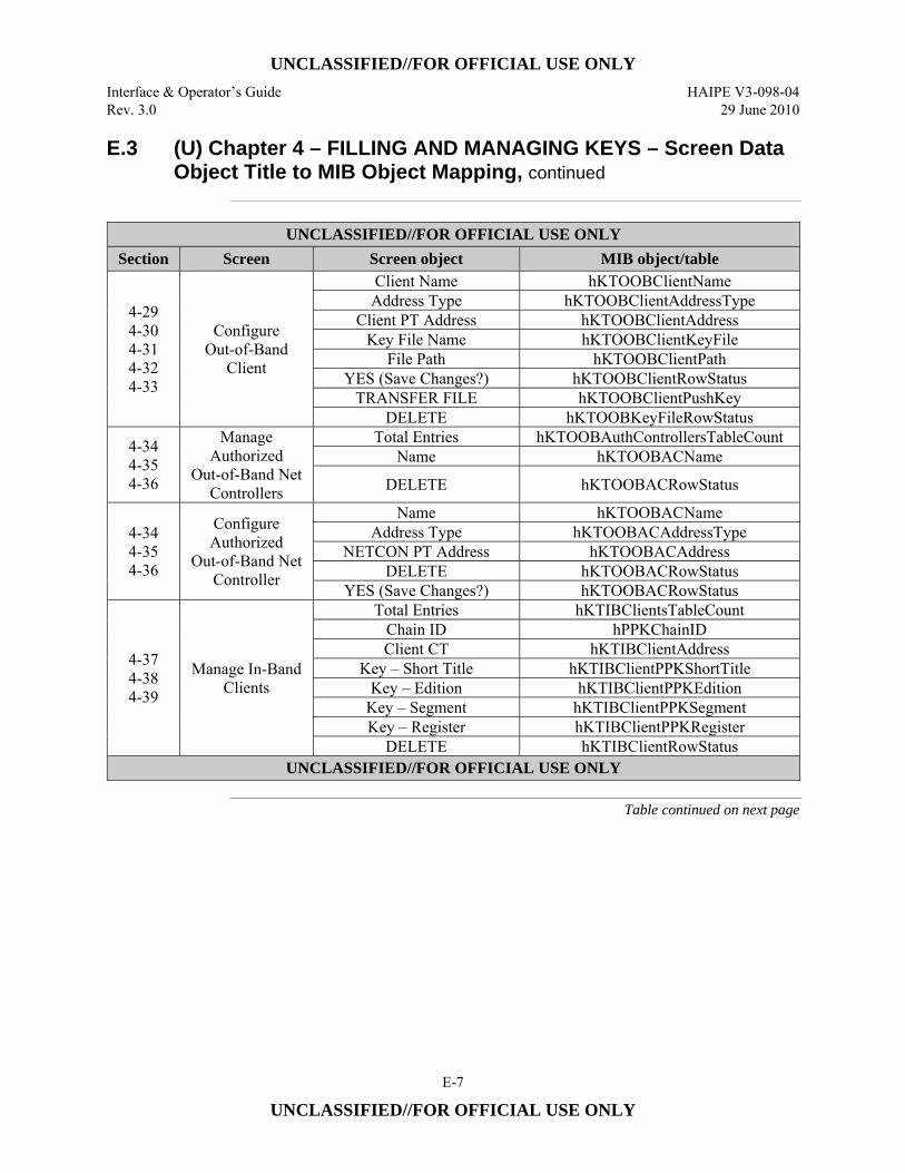
UNCLASSIFIED//FOR OFFICIAL USE ONLY
Interface & Operator’s Guide HAIPE V3-098-04 Rev. 3.0 29 June 2010
E-7
UNCLASSIFIED//FOR OFFICIAL USE ONLY
E.3 (U) Chapter 4 – FILLING AND MANAGING KEYS – Screen Data Object Title to MIB Object Mapping, continued
UNCLASSIFIED//FOR OFFICIAL USE ONLY
Section Screen Screen object MIB object/table
4-29 4-30 4-31 4-32 4-33
Configure Out-of-Band
Client
Client Name hKTOOBClientName Address Type hKTOOBClientAddressType
Client PT Address hKTOOBClientAddress Key File Name hKTOOBClientKeyFile
File Path hKTOOBClientPath YES (Save Changes?) hKTOOBClientRowStatus
TRANSFER FILE hKTOOBClientPushKey DELETE hKTOOBKeyFileRowStatus
4-34 4-35 4-36
Manage Authorized
Out-of-Band Net Controllers
Total Entries hKTOOBAuthControllersTableCount Name hKTOOBACName
DELETE hKTOOBACRowStatus
4-34 4-35 4-36
Configure Authorized
Out-of-Band Net Controller
Name hKTOOBACName Address Type hKTOOBACAddressType
NETCON PT Address hKTOOBACAddress DELETE hKTOOBACRowStatus
YES (Save Changes?) hKTOOBACRowStatus
4-37 4-38 4-39
Manage In-Band Clients
Total Entries hKTIBClientsTableCount Chain ID hPPKChainID Client CT hKTIBClientAddress
Key – Short Title hKTIBClientPPKShortTitle Key – Edition hKTIBClientPPKEdition
Key – Segment hKTIBClientPPKSegment Key – Register hKTIBClientPPKRegister
DELETE hKTIBClientRowStatus UNCLASSIFIED//FOR OFFICIAL USE ONLY
Table continued on next page
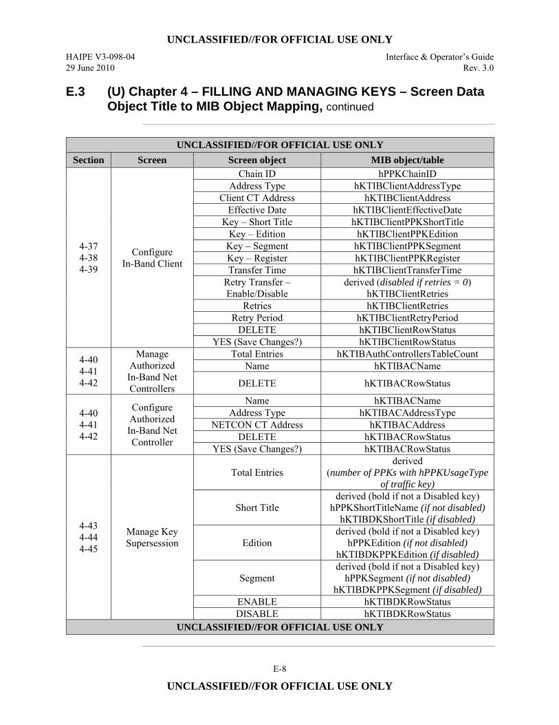
UNCLASSIFIED//FOR OFFICIAL USE ONLY
HAIPE V3-098-04 Interface & Operator’s Guide 29 June 2010 Rev. 3.0
E-8
UNCLASSIFIED//FOR OFFICIAL USE ONLY
E.3 (U) Chapter 4 – FILLING AND MANAGING KEYS – Screen Data Object Title to MIB Object Mapping, continued
UNCLASSIFIED//FOR OFFICIAL USE ONLY
Section Screen Screen object MIB object/table
4-37 4-38 4-39
Configure In-Band Client
Chain ID hPPKChainID Address Type hKTIBClientAddressType
Client CT Address hKTIBClientAddress Effective Date hKTIBClientEffectiveDate
Key – Short Title hKTIBClientPPKShortTitle Key – Edition hKTIBClientPPKEdition
Key – Segment hKTIBClientPPKSegment Key – Register hKTIBClientPPKRegister Transfer Time hKTIBClientTransferTime
Retry Transfer – Enable/Disable
derived (disabled if retries = 0) hKTIBClientRetries
Retries hKTIBClientRetries Retry Period hKTIBClientRetryPeriod
DELETE hKTIBClientRowStatus YES (Save Changes?) hKTIBClientRowStatus
4-40 4-41 4-42
Manage Authorized In-Band Net Controllers
Total Entries hKTIBAuthControllersTableCount Name hKTIBACName
DELETE hKTIBACRowStatus
4-40 4-41 4-42
Configure Authorized In-Band Net Controller
Name hKTIBACName Address Type hKTIBACAddressType
NETCON CT Address hKTIBACAddress DELETE hKTIBACRowStatus
YES (Save Changes?) hKTIBACRowStatus
4-43 4-44 4-45
Manage Key Supersession
Total Entries derived
(number of PPKs with hPPKUsageType of traffic key)
Short Title derived (bold if not a Disabled key)
hPPKShortTitleName (if not disabled) hKTIBDKShortTitle (if disabled)
Edition derived (bold if not a Disabled key)
hPPKEdition (if not disabled) hKTIBDKPPKEdition (if disabled)
Segment derived (bold if not a Disabled key)
hPPKSegment (if not disabled) hKTIBDKPPKSegment (if disabled)
ENABLE hKTIBDKRowStatus DISABLE hKTIBDKRowStatus
UNCLASSIFIED//FOR OFFICIAL USE ONLY
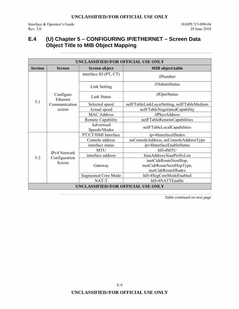
UNCLASSIFIED//FOR OFFICIAL USE ONLY
Interface & Operator’s Guide HAIPE V3-098-04 Rev. 3.0 29 June 2010
E-9
UNCLASSIFIED//FOR OFFICIAL USE ONLY
E.4 (U) Chapter 5 – CONFIGURING IP/ETHERNET – Screen Data Object Title to MIB Object Mapping
UNCLASSIFIED//FOR OFFICIAL USE ONLY
Section Screen Screen object MIB object/table
5.1
Configure Ethernet
Communication screen
interface ID (PT, CT) ifNumber
Link Setting ifAdminStatus
Link Status ifOperStatus
Selected speed neIFTableLinkLayerSetting, neIFTableMedium Actual speed neIFTableNegotiatedCapability
MAC Address ifPhysAddress Remote Capability neIFTableRemoteCapabilities
Advertised Speeds/Modes neIFTableLocalCapabilities
5-2 IPv4 Network Configuration
Screen
PT/CT/HMI Interface ipv4InterfaceIfIndex Console address neConsoleAddress, neConsoleAddressType interface status ipv4InterfaceEnableStatus
MTU hlfv4MTU interface address hiaaAddress/hiaaPrefixLen
Gateway inetCidrRouteNextHop,
inetCidrRouteNextHopType, inetCidrRouteIfIndex
Segmented Core Mode hIfv4SegCoreModeEnabled NAT-T hIfv4NATTEnable
UNCLASSIFIED//FOR OFFICIAL USE ONLY
Table continued on next page
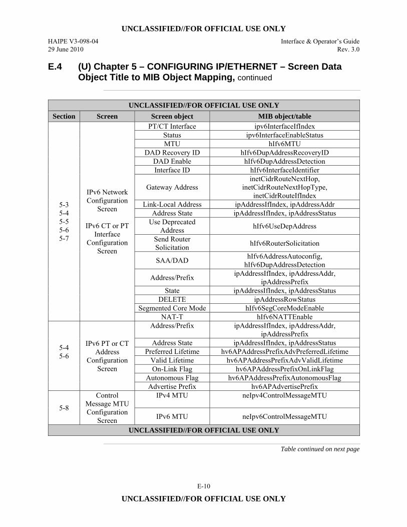
UNCLASSIFIED//FOR OFFICIAL USE ONLY
HAIPE V3-098-04 Interface & Operator’s Guide 29 June 2010 Rev. 3.0
E-10
UNCLASSIFIED//FOR OFFICIAL USE ONLY
E.4 (U) Chapter 5 – CONFIGURING IP/ETHERNET – Screen Data Object Title to MIB Object Mapping, continued
UNCLASSIFIED//FOR OFFICIAL USE ONLY
Section Screen Screen object MIB object/table
5-3 5-4 5-5 5-6 5-7
IPv6 Network Configuration
Screen
IPv6 CT or PT Interface
Configuration Screen
PT/CT Interface ipv6InterfaceIfIndex Status ipv6InterfaceEnableStatus MTU hIfv6MTU
DAD Recovery ID hIfv6DupAddressRecoveryID DAD Enable hIfv6DupAddressDetection Interface ID hIfv6InterfaceIdentifier
Gateway Address inetCidrRouteNextHop,
inetCidrRouteNextHopType, inetCidrRouteIfIndex
Link-Local Address ipAddressIfIndex, ipAddressAddr Address State ipAddressIfIndex, ipAddressStatus
Use Deprecated Address hIfv6UseDepAddress
Send Router Solicitation hIfv6RouterSolicitation
SAA/DAD hIfv6AddressAutoconfig, hIfv6DupAddressDetection
Address/Prefix ipAddressIfIndex, ipAddressAddr, ipAddressPrefix
State ipAddressIfIndex, ipAddressStatus DELETE ipAddressRowStatus
Segmented Core Mode hIfv6SegCoreModeEnable NAT-T hIfv6NATTEnable
5-4 5-6
IPv6 PT or CT Address
Configuration Screen
Address/Prefix
ipAddressIfIndex, ipAddressAddr, ipAddressPrefix
Address State ipAddressIfIndex, ipAddressStatus Preferred Lifetime hv6APAddressPrefixAdvPreferredLifetime
Valid Lifetime hv6APAddressPrefixAdvValidLifetime On-Link Flag hv6APAddressPrefixOnLinkFlag
Autonomous Flag hv6APAddressPrefixAutonomousFlag Advertise Prefix hv6APAdvertisePrefix
5-8
Control Message MTU Configuration
Screen
IPv4 MTU
neIpv4ControlMessageMTU
IPv6 MTU neIpv6ControlMessageMTU
UNCLASSIFIED//FOR OFFICIAL USE ONLY
Table continued on next page
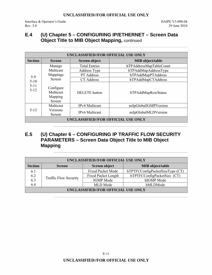
UNCLASSIFIED//FOR OFFICIAL USE ONLY
Interface & Operator’s Guide HAIPE V3-098-04 Rev. 3.0 29 June 2010
E-11
UNCLASSIFIED//FOR OFFICIAL USE ONLY
E.4 (U) Chapter 5 – CONFIGURING IP/ETHERNET – Screen Data Object Title to MIB Object Mapping, continued
UNCLASSIFIED//FOR OFFICIAL USE ONLY
Section Screen Screen object MIB object/table
5-9 5-10 5-11 5-12
Manage Multicast Mappings
Screen
Configure Multicast Mapping Screen
Total Entries hTPAddressMapTableCount Address Type hTPAddMapAddressType PT Address hTPAddMapPTAddress CT Address hTPAddMapCTAddress
DELETE button hTPAddMapRowStatus
5-13 Multicast Versions Screen
IPv4 Multicast neIpGlobalIGMPVersion
IPv6 Multicast neIpGlobalMLDVersion
UNCLASSIFIED//FOR OFFICIAL USE ONLY
E.5 (U) Chapter 6 – CONFIGURING IP TRAFFIC FLOW SECURITY
PARAMETERS – Screen Data Object Title to MIB Object Mapping
UNCLASSIFIED//FOR OFFICIAL USE ONLY
Section Screen Screen object MIB object/table 6.1 6.2 6.3 6.4
Traffic Flow Security
Fixed Packet Mode hTPTFCConfigPacketSizeType (CT) Fixed Packet Length hTPTFCConfigPacketSize (CT)
IGMP Mode hIGMP Mode MLD Mode hMLDMode
UNCLASSIFIED//FOR OFFICIAL USE ONLY
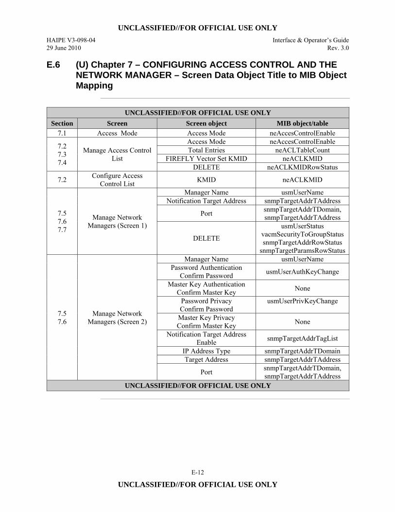
UNCLASSIFIED//FOR OFFICIAL USE ONLY
HAIPE V3-098-04 Interface & Operator’s Guide 29 June 2010 Rev. 3.0
E-12
UNCLASSIFIED//FOR OFFICIAL USE ONLY
E.6 (U) Chapter 7 – CONFIGURING ACCESS CONTROL AND THE NETWORK MANAGER – Screen Data Object Title to MIB Object Mapping
UNCLASSIFIED//FOR OFFICIAL USE ONLY
Section Screen Screen object MIB object/table 7.1 Access Mode Access Mode neAccesControlEnable
7.2 7.3 7.4
Manage Access Control List
Access Mode neAccesControlEnable Total Entries neACLTableCount
FIREFLY Vector Set KMID neACLKMID DELETE neACLKMIDRowStatus
7.2 Configure Access Control List KMID neACLKMID
7.5 7.6 7.7
Manage Network Managers (Screen 1)
Manager Name usmUserName Notification Target Address snmpTargetAddrTAddress
Port snmpTargetAddrTDomain, snmpTargetAddrTAddress
DELETE
usmUserStatus vacmSecurityToGroupStatus snmpTargetAddrRowStatus
snmpTargetParamsRowStatus
7.5 7.6
Manage Network Managers (Screen 2)
Manager Name usmUserName Password Authentication
Confirm Password usmUserAuthKeyChange
Master Key Authentication Confirm Master Key None
Password Privacy Confirm Password
usmUserPrivKeyChange
Master Key Privacy Confirm Master Key None
Notification Target Address Enable snmpTargetAddrTagList
IP Address Type snmpTargetAddrTDomain Target Address snmpTargetAddrTAddress
Port snmpTargetAddrTDomain, snmpTargetAddrTAddress
UNCLASSIFIED//FOR OFFICIAL USE ONLY
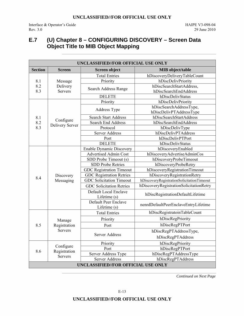
UNCLASSIFIED//FOR OFFICIAL USE ONLY
Interface & Operator’s Guide HAIPE V3-098-04 Rev. 3.0 29 June 2010
E-13
UNCLASSIFIED//FOR OFFICIAL USE ONLY
E.7 (U) Chapter 8 – CONFIGURING DISCOVERY – Screen Data Object Title to MIB Object Mapping
UNCLASSIFIED//FOR OFFICIAL USE ONLY
Section Screen Screen object MIB object/table
8.1 8.2 8.3
Message Delivery Servers
Total Entries hDiscoveryDeliveryTableCount Priority hDiscDelivPriority
Search Address Range hDiscSearchStartAddress, hDiscSearchEndAddress
DELETE hDiscDelivStatus
8.1 8.2 8.3
Configure Delivery Server
Priority hDiscDelivPriority
Address Type hDiscSearchAddressType, hDiscDelivPTAddressType
Search Start Address hDiscSearchStartAddress Search End Address hDiscSearchEndAddress
Protocol hDiscDelivType Server Address hDiscDelivPTAddress
Port hDiscDelivPTPort DELETE hDiscDelivStatus
8.4 Discovery Messaging
Enable Dynamic Discovery hDiscoveryEnabled Advertised Admin Cost hDiscoveryAdvertiseAdminCos SDD Probe Timeout (s) hDiscoveryProbeTimeout
SDD Probe Retries hDiscoveryProbeRetry GDC Registration Timeout hDiscoveryRegistrationTimeout GDC Registration Retries hDiscoveryRegistrationRetry GDC Solicitation Timeout hDiscoveryRegistrationSolicitationTimeout GDC Solicitation Retries hDiscoveryRegistrationSolicitationRetry
Default Local Enclave Lifetime (s) hDiscRegistrationDefaultLifetime
Default Peer Enclave Lifetime (s) nenrdDefaultPeerEnclaveEntryLifetime
8.5 Manage
Registration Servers
Total Entries hDiscRegistratoinTableCount Priority hDiscRegPriority
Port hDiscRegPTPort
Server Address hDiscRegPTAddressType,
hDiscRegPTAddress
8.6 Configure
Registration Servers
Priority hDiscRegPriority Port hDiscRegPTPort
Server Address Type hDiscRegPTAddressType Server Address hDiscRegPTAddress
UNCLASSIFIED//FOR OFFICIAL USE ONLY
Continued on Next Page
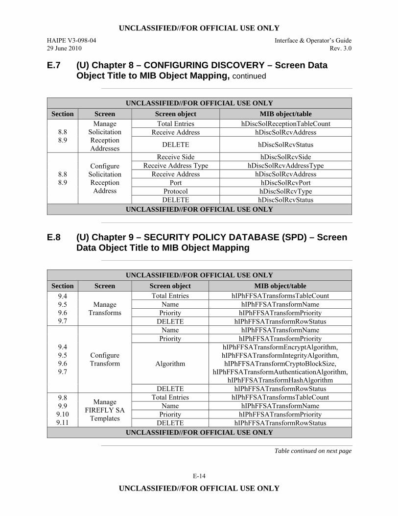
UNCLASSIFIED//FOR OFFICIAL USE ONLY
HAIPE V3-098-04 Interface & Operator’s Guide 29 June 2010 Rev. 3.0
E-14
UNCLASSIFIED//FOR OFFICIAL USE ONLY
E.7 (U) Chapter 8 – CONFIGURING DISCOVERY – Screen Data Object Title to MIB Object Mapping, continued
UNCLASSIFIED//FOR OFFICIAL USE ONLY
Section Screen Screen object MIB object/table
8.8 8.9
Manage Solicitation Reception Addresses
Total Entries hDiscSolReceptionTableCount Receive Address hDiscSolRcvAddress
DELETE hDiscSolRcvStatus
8.8 8.9
Configure Solicitation Reception Address
Receive Side hDiscSolRcvSide Receive Address Type hDiscSolRcvAddressType
Receive Address hDiscSolRcvAddress Port hDiscSolRcvPort
Protocol hDiscSolRcvType DELETE hDiscSolRcvStatus
UNCLASSIFIED//FOR OFFICIAL USE ONLY
E.8 (U) Chapter 9 – SECURITY POLICY DATABASE (SPD) – Screen
Data Object Title to MIB Object Mapping
UNCLASSIFIED//FOR OFFICIAL USE ONLY
Section Screen Screen object MIB object/table 9.4 9.5 9.6 9.7
Manage Transforms
Total Entries hIPhFFSATransformsTableCount Name hIPhFFSATransformName
Priority hIPhFFSATransformPriority DELETE hIPhFFSATransformRowStatus
9.4 9.5 9.6 9.7
Configure Transform
Name hIPhFFSATransformName Priority hIPhFFSATransformPriority
Algorithm
hIPhFFSATransformEncryptAlgorithm, hIPhFFSATransformIntegrityAlgorithm, hIPhFFSATransformCryptoBlockSize,
hIPhFFSATransformAuthenticationAlgorithm, hIPhFFSATransformHashAlgorithm
DELETE hIPhFFSATransformRowStatus 9.8 9.9
9.10 9.11
Manage FIREFLY SA
Templates
Total Entries hIPhFFSATransformsTableCount Name hIPhFFSATransformName
Priority hIPhFFSATransformPriority DELETE hIPhFFSATransformRowStatus
UNCLASSIFIED//FOR OFFICIAL USE ONLY
Table continued on next page
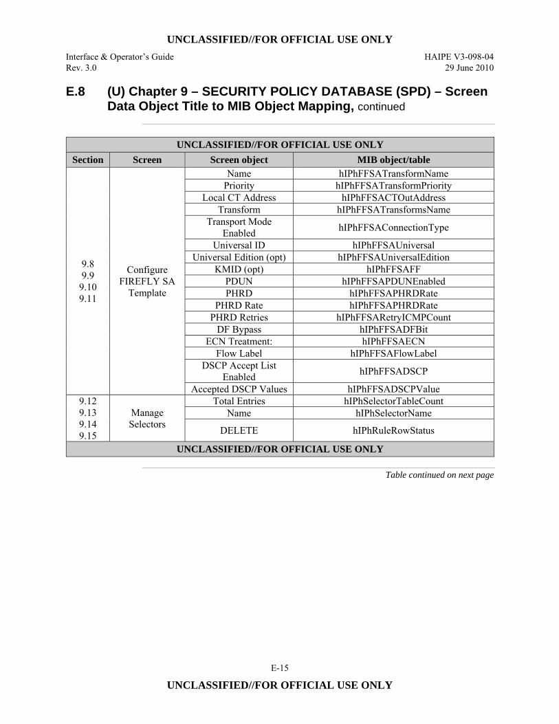
UNCLASSIFIED//FOR OFFICIAL USE ONLY
Interface & Operator’s Guide HAIPE V3-098-04 Rev. 3.0 29 June 2010
E-15
UNCLASSIFIED//FOR OFFICIAL USE ONLY
E.8 (U) Chapter 9 – SECURITY POLICY DATABASE (SPD) – Screen Data Object Title to MIB Object Mapping, continued
UNCLASSIFIED//FOR OFFICIAL USE ONLY
Section Screen Screen object MIB object/table
9.8 9.9
9.10 9.11
Configure FIREFLY SA
Template
Name hIPhFFSATransformName Priority hIPhFFSATransformPriority
Local CT Address hIPhFFSACTOutAddress Transform hIPhFFSATransformsName
Transport Mode Enabled hIPhFFSAConnectionType
Universal ID hIPhFFSAUniversal Universal Edition (opt) hIPhFFSAUniversalEdition
KMID (opt) hIPhFFSAFF PDUN hIPhFFSAPDUNEnabled PHRD hIPhFFSAPHRDRate
PHRD Rate hIPhFFSAPHRDRate PHRD Retries hIPhFFSARetryICMPCount
DF Bypass hIPhFFSADFBit ECN Treatment: hIPhFFSAECN
Flow Label hIPhFFSAFlowLabel DSCP Accept List
Enabled hIPhFFSADSCP
Accepted DSCP Values hIPhFFSADSCPValue 9.12 9.13 9.14 9.15
Manage Selectors
Total Entries hIPhSelectorTableCount Name hIPhSelectorName
DELETE hIPhRuleRowStatus
UNCLASSIFIED//FOR OFFICIAL USE ONLY
Table continued on next page
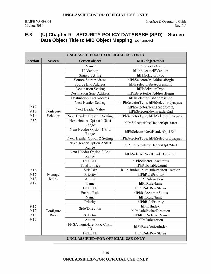
UNCLASSIFIED//FOR OFFICIAL USE ONLY
HAIPE V3-098-04 Interface & Operator’s Guide 29 June 2010 Rev. 3.0
E-16
UNCLASSIFIED//FOR OFFICIAL USE ONLY
E.8 (U) Chapter 9 – SECURITY POLICY DATABASE (SPD) – Screen Data Object Title to MIB Object Mapping, continued
UNCLASSIFIED//FOR OFFICIAL USE ONLY
Section Screen Screen object MIB object/table
9.12 9.13 9.14 9.15
Configure Selector
Name hIPhSelectorName IP Version hIPhSelectorIPVersion
Source Setting hIPhSelectorType Source Start Address hIPhSelectorSrcAddressBegin Source End Address hIPhSelectorSrcAddressEnd Destination Setting hIPhSelectorType
Destination Start Address hIPhSelectorDstAddressBegin Destination End Address hIPhSelectorDstAddressEnd
Next Header Setting hIPhSelectorType, hIPhSelectorOpaques
Next Header Value hIPhSelectorNextHeaderStart, hIPhSelectorNextHeaderEnd
Next Header Option 1 Setting hIPhSelectorType, hIPhSelectorOpaques Next Header Option 1 Start
Range hIPhSelectorNextHeaderOpt1Start
Next Header Option 1 End Range hIPhSelectorNextHeaderOpt1End
Next Header Option 2 Setting hIPhSelectorType, hIPhSelectorOpaques Next Header Option 2 Start
Range hIPhSelectorNextHeaderOpt2Start
Next Header Option 2 End Range hIPhSelectorNextHeaderOpt2End
DELETE hIPhSelectorRowStatus
9.16 9.17 9.18 9.19
Manage Rules
Total Entries hIPhRuleTableCount Side/Dir hIPhIfIndex, hIPhRulePacketDirection Priority hIPhRulePriority Action hIPhRuleAction Name hIPhRuleName
DELETE hIPhRuleRowStatus
9.16 9.17 9.18 9.19
Configure Rule
Enable Rule hIPhRuleAdminStatus Name hIPhRuleName
Priority hIPhRulePriority
Side/Direction hIPhIfIndex, hIPhRulePacketDirection
Selector hIPhRuleSelectorName Action hIPhRuleAction
FF SA Template/ PPK Chain ID hIPhRuleActionIndex
DELETE hIPhRuleRowStatus UNCLASSIFIED//FOR OFFICIAL USE ONLY
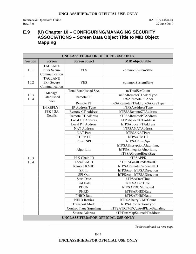
UNCLASSIFIED//FOR OFFICIAL USE ONLY
Interface & Operator’s Guide HAIPE V3-098-04 Rev. 3.0 29 June 2010
E-17
UNCLASSIFIED//FOR OFFICIAL USE ONLY
E.9 (U) Chapter 10 – CONFIGURING/MANAGING SECURITY ASSOCIATIONS – Screen Data Object Title to MIB Object Mapping
UNCLASSIFIED//FOR OFFICIAL USE ONLY
Section Screen Screen object MIB object/table
10.1 TACLANE Enter Secure
Communication YES commonSystemState
10.2 TACLANE Exit Secure
Communication YES commonSystemState
10.3 10.4
Manage Established
SAs
Total Established SAs neTotalSACount
Remote CT neSARemoteCTAddrType neSARemoteCTAddr
Remote PT neSARemotePTAddr, neSAKeyType
10.3 10.4
[FIREFLY | PPK ] SA
Details
IP Address Type hTPSAAddressType Remote CT Address hTPSARemoteCTAddress Remote PT Address hTPSARemotePTAddress Local CT Address hTPSALocalCTAddress Local PT Address hTPSALocalPTAddress
NAT Address hTPSANATAddress NAT Port hTPSANATPort PT PMTU hTPSAPMTU Reuse SPI hTPSAReuseSpi
Algorithm hTPSAEncryptionAlgorithm, hTPSAIntegrityAlgorithm, hTPSACryptoBlockSize
PPK Chain ID hTPSAPPK Local KMID hTPSALocalCredentialID
Remote KMID hTPSARemoteCredentialID SPI In hTPSAspi, hTPSADirection
SPI Out hTPSAspi, hTPSADirection Start Date hTPSAStartTime End Date hTPSAEndTime
PDUN hTPSAPDUNEnabled PHRD hTPSAPHRDRate
PHRD Rate hTPSAPHRDRate PHRD Retries hTPSARetryICMPCount
Transport Mode hTPSAConnectionType Control Plane Signaling hTPSATRPMDControlPlaneSignaling
Source Address hTPTansMapSourcePTAddress UNCLASSIFIED//FOR OFFICIAL USE ONLY
Table continued on next page

UNCLASSIFIED//FOR OFFICIAL USE ONLY
HAIPE V3-098-04 Interface & Operator’s Guide 29 June 2010 Rev. 3.0
E-18
UNCLASSIFIED//FOR OFFICIAL USE ONLY
E.9 (U) Chapter 10 – CONFIGURING/MANAGING SECURITY ASSOCIATIONS – Screen Data Object Title to MIB Object Mapping, continued
UNCLASSIFIED//FOR OFFICIAL USE ONLY
Section Screen Screen object MIB object/table Destination Address hTPTransMapDestPTAddress
DF Bypass hTPSADFBit ECN Treatment hTPSAECN
Flow Label hTPSAFlowLabel DSCP Accept List hTPSADSCP
Accepted DSCP Values hTPSADSCPValue DELETE hTPSARowStatus
10.5 Configure
Router Advertisements
Send Advertisements ipv6RouterAdvertSentAdverts Link MTU ipv6RouterAdvertLinkMTU
Current Hop Limit ipv6RouterAdvertCurHopLimit Default Lifetime ipv6RouterAdvertDefaultLifetime
Minimum Interval (sec) ipv6RouterAdvertMinInterval Maximum Interval (sec) ipv6RouterAdvertMaxInterval Reachable Time (msec) ipv6RouterAdvertReachableTime Retransmit Time (msec) ipv6RouterAdvertRetransmitTime
Managed Flag ipv6RouterAdvertManagedFlag Other Flag ipv6RouterAdvertOtherConfigFlag
10.6 10.7 10.8
Manage Peer Enclave Routes
Total Entries hRemoteEnclaveTableCount
Host/Prefix hRemoteEnclaveDestHost, hRemoteEnclaveDestHostPTPfxLen
ECU CT hRemoteEnclaveDestHaipeCTAddr Route Type hRemoteEnclaveMethod DELETE hRemoteEnclaveRowStatus
DELETE ALL neDeleteAllRoutes
10.6 10.7 10.8
Configure Peer Enclave Route
Route Type hRemoteEnclaveMethod
IP Address Type hRemoteEnclaveDest[Host or HaipeCT or HaipePT]AddrType
Host Address hRemoteEnclaveDestHost Host Prefix hRemoteEnclaveDestHostPTPfxLen
ECU CT Address hRemoteEnclaveDestHaipeCTAddr ECU PT Address hRemoteEnclaveDestHaipePTAddr
NAT Address hRemoteEnclaveDestHaipeNATAddr NAT Port hRemoteEnclaveDestHaipeNATPort
Admin Cost hRemoteEnclaveDestAdminCost Lifetime hRemoteEnclaveLifetime DELETE hRemoteEnclaveRowStatus
UNCLASSIFIED//FOR OFFICIAL USE ONLY
Table continued on next page
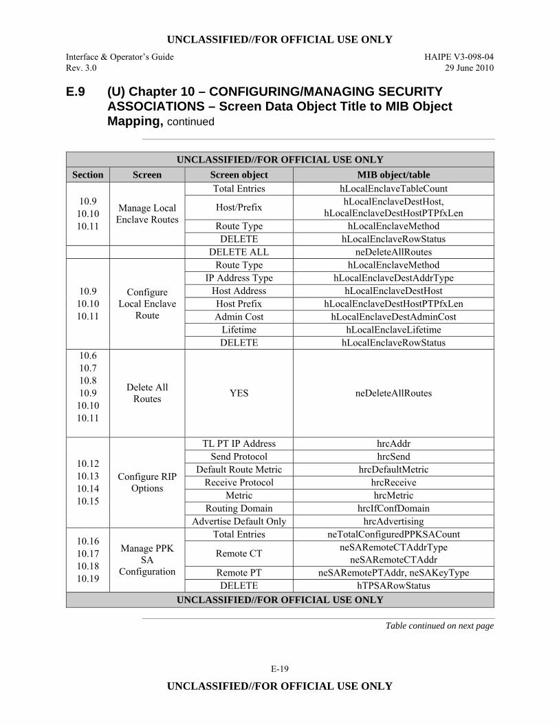
UNCLASSIFIED//FOR OFFICIAL USE ONLY
Interface & Operator’s Guide HAIPE V3-098-04 Rev. 3.0 29 June 2010
E-19
UNCLASSIFIED//FOR OFFICIAL USE ONLY
E.9 (U) Chapter 10 – CONFIGURING/MANAGING SECURITY ASSOCIATIONS – Screen Data Object Title to MIB Object Mapping, continued
UNCLASSIFIED//FOR OFFICIAL USE ONLY
Section Screen Screen object MIB object/table
10.9 10.10 10.11
Manage Local Enclave Routes
Total Entries hLocalEnclaveTableCount
Host/Prefix hLocalEnclaveDestHost, hLocalEnclaveDestHostPTPfxLen
Route Type hLocalEnclaveMethod DELETE hLocalEnclaveRowStatus
DELETE ALL neDeleteAllRoutes
10.9 10.10 10.11
Configure Local Enclave
Route
Route Type hLocalEnclaveMethod IP Address Type hLocalEnclaveDestAddrType
Host Address hLocalEnclaveDestHost Host Prefix hLocalEnclaveDestHostPTPfxLen Admin Cost hLocalEnclaveDestAdminCost
Lifetime hLocalEnclaveLifetime DELETE hLocalEnclaveRowStatus
10.6 10.7 10.8 10.9
10.10 10.11
Delete All Routes YES neDeleteAllRoutes
10.12 10.13 10.14 10.15
Configure RIP Options
TL PT IP Address hrcAddr Send Protocol hrcSend
Default Route Metric hrcDefaultMetric Receive Protocol hrcReceive
Metric hrcMetric Routing Domain hrcIfConfDomain
Advertise Default Only hrcAdvertising
10.16 10.17 10.18 10.19
Manage PPK SA
Configuration
Total Entries neTotalConfiguredPPKSACount
Remote CT neSARemoteCTAddrType neSARemoteCTAddr
Remote PT neSARemotePTAddr, neSAKeyType DELETE hTPSARowStatus
UNCLASSIFIED//FOR OFFICIAL USE ONLY
Table continued on next page
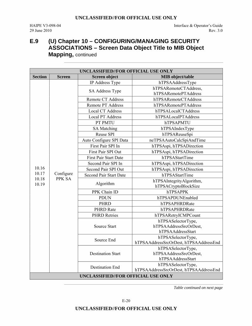
UNCLASSIFIED//FOR OFFICIAL USE ONLY
HAIPE V3-098-04 Interface & Operator’s Guide 29 June 2010 Rev. 3.0
E-20
UNCLASSIFIED//FOR OFFICIAL USE ONLY
E.9 (U) Chapter 10 – CONFIGURING/MANAGING SECURITY ASSOCIATIONS – Screen Data Object Title to MIB Object Mapping, continued
UNCLASSIFIED//FOR OFFICIAL USE ONLY
Section Screen Screen object MIB object/table
10.16 10.17 10.18 10.19
Configure PPK SA
IP Address Type hTPSAAddressType
SA Address Type hTPSARemoteCTAddress, hTPSARemotePTAddress
Remote CT Address hTPSARemoteCTAddress Remote PT Address hTPSARemotePTAddress Local CT Address hTPSALocalCTAddress Local PT Address hTPSALocalPTAddress
PT PMTU hTPSAPMTU SA Matching hTPSAIndexType
Reuse SPI hTPSAReuseSpi Auto Configure SPI Data neTPSAAutoCalcSpiAndTime
First Pair SPI In hTPSAspi, hTPSADirection First Pair SPI Out hTPSAspi, hTPSADirection
First Pair Start Date hTPSAStartTime Second Pair SPI In hTPSAspi, hTPSADirection
Second Pair SPI Out hTPSAspi, hTPSADirection Second Pair Start Date hTPSAStartTime
Algorithm hTPSAIntegrityAlgorithm, hTPSACryptoBlockSize
PPK Chain ID hTPSAPPK PDUN hTPSAPDUNEnabled PHRD hTPSAPHRDRate
PHRD Rate hTPSAPHRDRate PHRD Retries hTPSARetryICMPCount
Source Start hTPSASelectorType,
hTPSAAddressSrcOrDest, hTPSAAddressStart
Source End hTPSASelectorType, hTPSAAddressSrcOrDest, hTPSAAddressEnd
Destination Start hTPSASelectorType,
hTPSAAddressSrcOrDest, hTPSAAddressStart
Destination End hTPSASelectorType, hTPSAAddressSrcOrDest, hTPSAAddressEnd
UNCLASSIFIED//FOR OFFICIAL USE ONLY
Table continued on next page
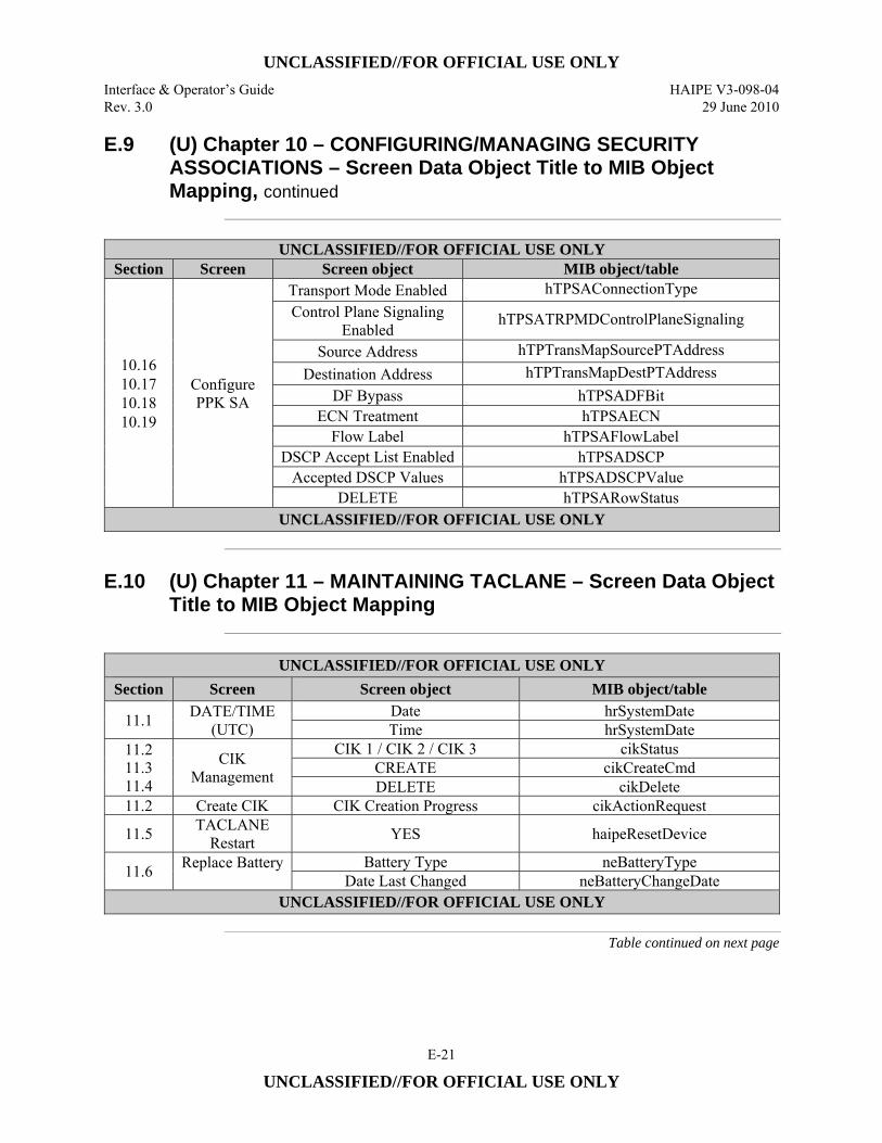
UNCLASSIFIED//FOR OFFICIAL USE ONLY
Interface & Operator’s Guide HAIPE V3-098-04 Rev. 3.0 29 June 2010
E-21
UNCLASSIFIED//FOR OFFICIAL USE ONLY
E.9 (U) Chapter 10 – CONFIGURING/MANAGING SECURITY ASSOCIATIONS – Screen Data Object Title to MIB Object Mapping, continued
UNCLASSIFIED//FOR OFFICIAL USE ONLY
Section Screen Screen object MIB object/table
10.16 10.17 10.18 10.19
Configure PPK SA
Transport Mode Enabled hTPSAConnectionType Control Plane Signaling
Enabled hTPSATRPMDControlPlaneSignaling
Source Address hTPTransMapSourcePTAddress Destination Address hTPTransMapDestPTAddress
DF Bypass hTPSADFBit ECN Treatment hTPSAECN
Flow Label hTPSAFlowLabel DSCP Accept List Enabled hTPSADSCP
Accepted DSCP Values hTPSADSCPValue DELETE hTPSARowStatus
UNCLASSIFIED//FOR OFFICIAL USE ONLY
E.10 (U) Chapter 11 – MAINTAINING TACLANE – Screen Data Object
Title to MIB Object Mapping
UNCLASSIFIED//FOR OFFICIAL USE ONLY
Section Screen Screen object MIB object/table
11.1 DATE/TIME (UTC)
Date hrSystemDate Time hrSystemDate
11.2 11.3 11.4
CIK Management
CIK 1 / CIK 2 / CIK 3 cikStatus CREATE cikCreateCmd DELETE cikDelete
11.2 Create CIK CIK Creation Progress cikActionRequest
11.5 TACLANE Restart YES haipeResetDevice
11.6 Replace Battery
Battery Type neBatteryType Date Last Changed neBatteryChangeDate
UNCLASSIFIED//FOR OFFICIAL USE ONLY
Table continued on next page
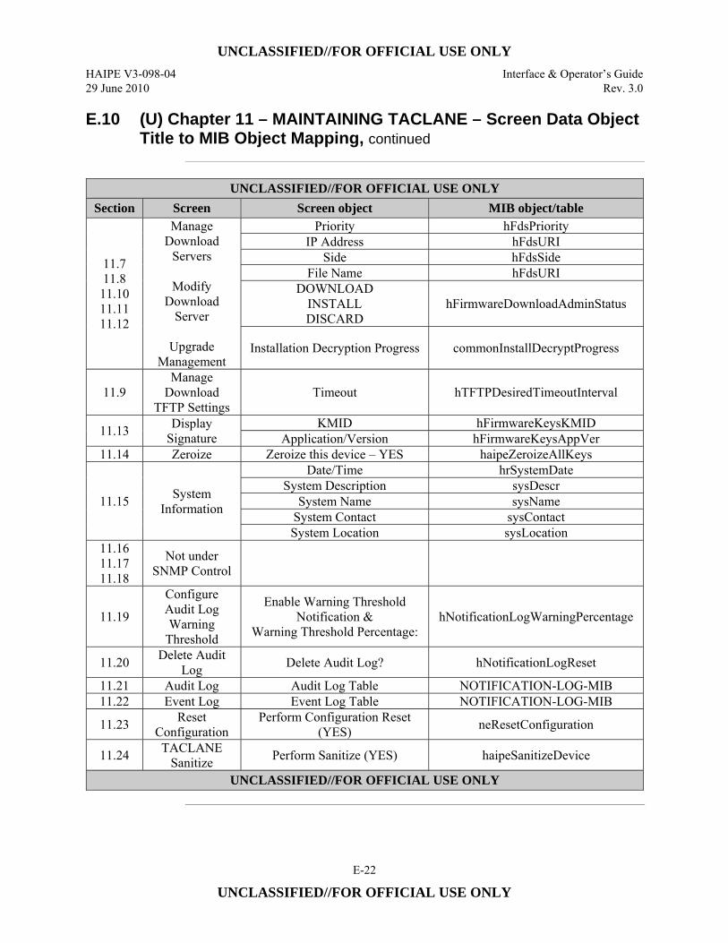
UNCLASSIFIED//FOR OFFICIAL USE ONLY
HAIPE V3-098-04 Interface & Operator’s Guide 29 June 2010 Rev. 3.0
E-22
UNCLASSIFIED//FOR OFFICIAL USE ONLY
E.10 (U) Chapter 11 – MAINTAINING TACLANE – Screen Data Object Title to MIB Object Mapping, continued
UNCLASSIFIED//FOR OFFICIAL USE ONLY
Section Screen Screen object MIB object/table
11.7 11.8
11.10 11.11 11.12
Manage Download
Servers
Modify Download
Server
Upgrade Management
Priority hFdsPriority IP Address hFdsURI
Side hFdsSide File Name hFdsURI
DOWNLOAD INSTALL DISCARD
hFirmwareDownloadAdminStatus
Installation Decryption Progress commonInstallDecryptProgress
11.9 Manage
Download TFTP Settings
Timeout hTFTPDesiredTimeoutInterval
11.13 Display Signature
KMID hFirmwareKeysKMID Application/Version hFirmwareKeysAppVer
11.14 Zeroize Zeroize this device – YES haipeZeroizeAllKeys
11.15 System Information
Date/Time hrSystemDate System Description sysDescr
System Name sysName System Contact sysContact System Location sysLocation
11.16 11.17 11.18
Not under SNMP Control
11.19
Configure Audit Log Warning
Threshold
Enable Warning Threshold Notification &
Warning Threshold Percentage: hNotificationLogWarningPercentage
11.20 Delete Audit Log Delete Audit Log? hNotificationLogReset
11.21 Audit Log Audit Log Table NOTIFICATION-LOG-MIB 11.22 Event Log Event Log Table NOTIFICATION-LOG-MIB
11.23 Reset Configuration
Perform Configuration Reset (YES) neResetConfiguration
11.24 TACLANE Sanitize Perform Sanitize (YES) haipeSanitizeDevice
UNCLASSIFIED//FOR OFFICIAL USE ONLY
UNCLASSIFIED//FOR OFFICIAL USE ONLY
Interface & Operator’s Guide HAIPE V3-098-04 Rev. 3.0 29 June 2010
F-1
UNCLASSIFIED//FOR OFFICIAL USE ONLY
Appendix F (U) GDC Background and TIPS
F.1 (U) GDC Background
Background (U//FOUO) Generic Discovery Client is a new concept introduced in HAIPE IS v3 to
provide automatic discovery functionality to ECUs which cannot associate a remote plaintext host with a particular remote ECU. Generic Discovery Client provides functions that are similar to those that are provided by Secure Dynamic Discovery which was used in HAIPE IS v1.3.5. (U//FOUO) The Generic Discovery Client functionality is being introduced into the HAIPE IS in order to provide a more scalable secure discovery solution than what was provided by Secure Dynamic Discovery in HAIPE IS v1.3.5. (U//FOUO) The Discovery process will work in the same fashion as it did in HAIPE IS v1.3.5 compliant devices. The ECU will enforce Security Policy Database rules on packets received on the PT interface. The ECU will determine if the traffic needs to be protected, dropped or bypassed. If the policy is protect, the ECU will attempt to map the packet onto an existing Security Association (SA). If the ECU cannot determine an SA to map the packet onto, it will initiate the Discovery process for the destination address in the IP packet header. Depending on the device configuration (the Discovery Delivery Table), the Discovery processes could initiate a Solicitation Query to the Generic Discovery Server, a Solicitation Query to a peer ECU, or could send a Secure Dynamic Discovery Probe to the SDD multicast network looking for the peer ECU that is protecting the destination address of the packet. (U//FOUO) If the device receives a response to the Discovery request, the ECU will use the information in the response to determine if it currently has an SA to the peer ECU or if the ECU must create a new SA to the peer ECU because one does not already exist. When adding the remote PT address to an existing or new SA, the ECU will populate the Remote Enclave Table with the remote prefix of the target destination, the associated peer ECU PT and CT addresses, and the administrative cost of the SA. Additionally, the ECU will place the fast path traffic on to the correct SA.
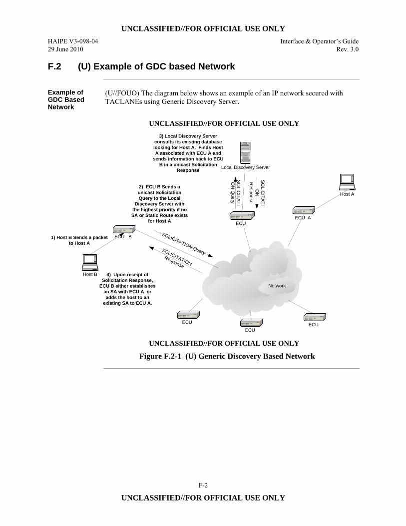
UNCLASSIFIED//FOR OFFICIAL USE ONLY
HAIPE V3-098-04 Interface & Operator’s Guide 29 June 2010 Rev. 3.0
F-2
UNCLASSIFIED//FOR OFFICIAL USE ONLY
F.2 (U) Example of GDC based Network
Example of GDC Based Network
(U//FOUO) The diagram below shows an example of an IP network secured with TACLANEs using Generic Discovery Server.
UNCLASSIFIED//FOR OFFICIAL USE ONLY
Local Discovery Server
Network
ECUECUECU
ECU B
ECUECU A
Host A
SOLICITATION QuerySOLICITATION Response
Host B
1) Host B Sends a packet to Host A
2) ECU B Sends a unicast Solicitation Query to the Local
Discovery Server with the highest priority if no SA or Static Route exists
for Host A
SOLIC
ITATIO
N Q
uery
SOLIC
ITATIO
N
Response
4) Upon receipt of Solicitation Response,
ECU B either establishes an SA with ECU A or adds the host to an
existing SA to ECU A.
3) Local Discovery Server consults its existing database looking for Host A. Finds Host A associated with ECU A and
sends information back to ECU B in a unicast Solicitation
Response
UNCLASSIFIED//FOR OFFICIAL USE ONLY
Figure F.2-1 (U) Generic Discovery Based Network
UNCLASSIFIED//FOR OFFICIAL USE ONLY
Interface & Operator’s Guide HAIPE V3-098-04 Rev. 3.0 29 June 2010
F-3
UNCLASSIFIED//FOR OFFICIAL USE ONLY
F.3 (U) GDC Configuration Tips
Introduction (U//FOUO) Listed below are some general TACLANE GDC configuration tips.
Basis Steps to Configure GDC
(U//FOUO) To configure a TACLANE for GDC, the following steps must be taken: 1. (U//FOUO) Configure a Discovery Delivery Server with protocol type = GDC. 2. (U//FOUO) Configure Discovery Messaging. 3. (U//FOUO) Configure Solicitation Reception Address with protocol type = GDC
(when no Generic Discovery Server is used). 4. (U//FOUO) Configure Registration Server (when Generic Discovery Server is
used).
Continued on Next Page
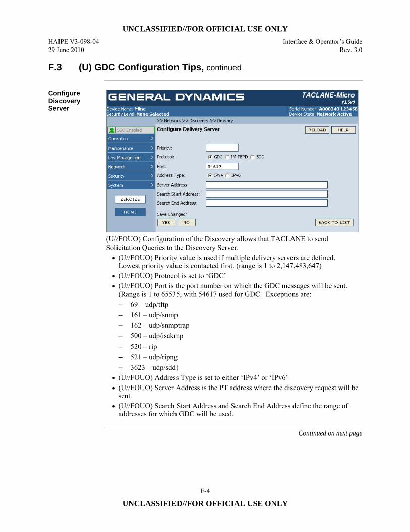
UNCLASSIFIED//FOR OFFICIAL USE ONLY
HAIPE V3-098-04 Interface & Operator’s Guide 29 June 2010 Rev. 3.0
F-4
UNCLASSIFIED//FOR OFFICIAL USE ONLY
F.3 (U) GDC Configuration Tips, continued
Configure Discovery Server
(U//FOUO) Configuration of the Discovery allows that TACLANE to send Solicitation Queries to the Discovery Server. • (U//FOUO) Priority value is used if multiple delivery servers are defined.
Lowest priority value is contacted first. (range is 1 to 2,147,483,647) • (U//FOUO) Protocol is set to ‘GDC’ • (U//FOUO) Port is the port number on which the GDC messages will be sent.
(Range is 1 to 65535, with 54617 used for GDC. Exceptions are: – 69 – udp/tftp – 161 – udp/snmp – 162 – udp/snmptrap – 500 – udp/isakmp – 520 – rip – 521 – udp/ripng – 3623 – udp/sdd)
• (U//FOUO) Address Type is set to either ‘IPv4’ or ‘IPv6’ • (U//FOUO) Server Address is the PT address where the discovery request will be
sent. • (U//FOUO) Search Start Address and Search End Address define the range of
addresses for which GDC will be used.
Continued on next page
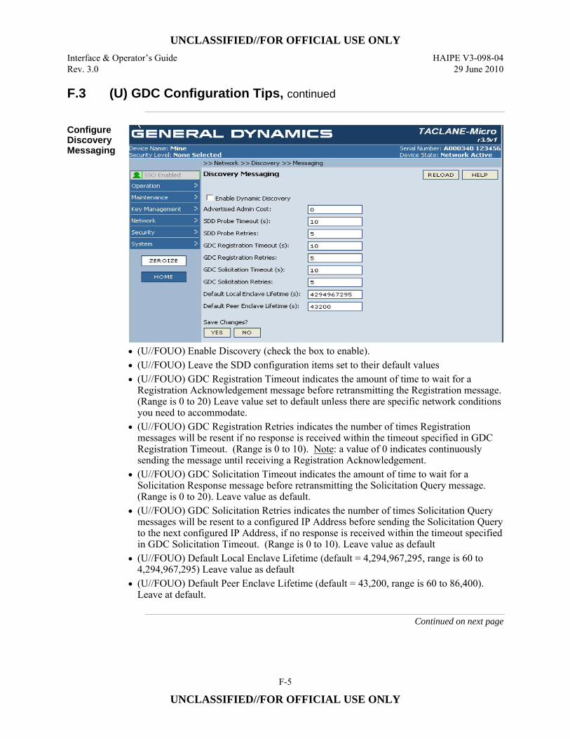
UNCLASSIFIED//FOR OFFICIAL USE ONLY
Interface & Operator’s Guide HAIPE V3-098-04 Rev. 3.0 29 June 2010
F-5
UNCLASSIFIED//FOR OFFICIAL USE ONLY
F.3 (U) GDC Configuration Tips, continued
Configure Discovery Messaging
• (U//FOUO) Enable Discovery (check the box to enable). • (U//FOUO) Leave the SDD configuration items set to their default values • (U//FOUO) GDC Registration Timeout indicates the amount of time to wait for a
Registration Acknowledgement message before retransmitting the Registration message. (Range is 0 to 20) Leave value set to default unless there are specific network conditions you need to accommodate.
• (U//FOUO) GDC Registration Retries indicates the number of times Registration messages will be resent if no response is received within the timeout specified in GDC Registration Timeout. (Range is 0 to 10). Note: a value of 0 indicates continuously sending the message until receiving a Registration Acknowledgement.
• (U//FOUO) GDC Solicitation Timeout indicates the amount of time to wait for a Solicitation Response message before retransmitting the Solicitation Query message. (Range is 0 to 20). Leave value as default.
• (U//FOUO) GDC Solicitation Retries indicates the number of times Solicitation Query messages will be resent to a configured IP Address before sending the Solicitation Query to the next configured IP Address, if no response is received within the timeout specified in GDC Solicitation Timeout. (Range is 0 to 10). Leave value as default
• (U//FOUO) Default Local Enclave Lifetime (default = 4,294,967,295, range is 60 to 4,294,967,295) Leave value as default
• (U//FOUO) Default Peer Enclave Lifetime (default = 43,200, range is 60 to 86,400). Leave at default.
Continued on next page
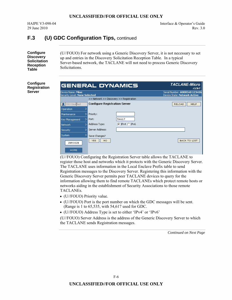
UNCLASSIFIED//FOR OFFICIAL USE ONLY
HAIPE V3-098-04 Interface & Operator’s Guide 29 June 2010 Rev. 3.0
F-6
UNCLASSIFIED//FOR OFFICIAL USE ONLY
F.3 (U) GDC Configuration Tips, continued
Configure Discovery Solicitation Reception Table
(U//FOUO) For network using a Generic Discovery Server, it is not necessary to set up and entries in the Discovery Solicitation Reception Table. In a typical Server-based network, the TACLANE will not need to process Generic Discovery Solicitations.
Configure Registration Server
(U//FOUO) Configuring the Registration Server table allows the TACLANE to register those host and networks which it protects with the Generic Discovery Server. The TACLANE uses information in the Local Enclave Prefix table to send Registration messages to the Discovery Server. Registering this information with the Generic Discovery Server permits peer TACLANE devices to query for the information allowing them to find remote TACLANEs which protect remote hosts or networks aiding in the establishment of Security Associations to those remote TACLANEs. • (U//FOUO) Priority value. • (U//FOUO) Port is the port number on which the GDC messages will be sent.
(Range is 1 to 65,535, with 54,617 used for GDC. • (U//FOUO) Address Type is set to either ‘IPv4’ or ‘IPv6’ (U//FOUO) Server Address is the address of the Generic Discovery Server to which the TACLANE sends Registration messages.
Continued on Next Page
UNCLASSIFIED//FOR OFFICIAL USE ONLY
Interface & Operator’s Guide HAIPE V3-098-04 Rev. 3.0 29 June 2010
F-7
UNCLASSIFIED//FOR OFFICIAL USE ONLY
F.3 (U) GDC Configuration Tips, continued
Configure Route and Security Association Information related to the Discovery Server
(U//FOUO) In order for Solicitation Queries to go out to the Discovery Server a static route must be set up in the Remote Enclave Prefix table detailing which remote TACLANE fronts the Discovery Server. Additionally, information regarding the Type of Security Association on which the Solicitation Query will be placed on needs to be configured within the TACLANE. Generic Discovery messages can be placed on FIREFLY on Traditional Key protected SAs. Registration Messages will be placed on the same SA.
Configuration of the TACLANE fronting the Discovery Server
(U//FOUO) The TACLANE fronting the Discovery Server will be configured differently than TACLANEs in the network which are querying the Discovery Server. This is due to the Discovery Server being located on the PT side of the TACLANE. The main differences are listed below:
1. (U//FOUO) The route for the Discovery Server needs to be placed in the Local Enclave Table instead of the Peer Enclave Table for the other TACLANEs on the network.
2. (U//FOUO) No SA is required to get to the Discovery Server, since it is located on the PT network.
3. (U//FOUO) No Registration messages are required, since the Discovery Server is located on the PT network of the Fronting TACLANE.
UNCLASSIFIED//FOR OFFICIAL USE ONLY
HAIPE V3-098-04 Interface & Operator’s Guide 29 June 2010 Rev. 3.0
F-8
UNCLASSIFIED//FOR OFFICIAL USE ONLY
F.4 (U) Using GDC without a Generic Discovery Server
Introduction (U//FOUO) GDC can be used without the presence of a Generic Discovery Server
client. Below are instructions on how to configure TACLANEs to use GDC without a Generic Discovery Server
Using GDC without the Generic Discovery Server
1. (U//FOUO) Update Date and Time, if necessary, to be current and approximately the same on each of the TACLANEs.
2. (U//FOUO) Fill compatible FIREFLY Vector Sets (FFVS) on each TACLANE. 3. (U//FOUO) Configure IPv4 and/or IPv6 addresses on each TACLANE. 4. (U//FOUO) Set Security Level on each TACLANE to the classification of the
FFVS. 5. (U//FOUO) Enter Secure Comm on each TACLANE. 6. (U//FOUO) Create a FIREFLY SA Template on each TACLANE
• Set Priority to be between 1 and 65535 • Local CT Address is Auto-configured • Select a Transform corresponding to the capability of the FFVS. • Set the Key Details (Universal ID, Universal Edition, KMID) to the values
of the loaded FFVS. Universal Edition and KMID are optional fields. • Leave TFS Settings (DF Bypass, ECN Treatment, DSCP Accept List
Enabled) as the defaults. 7. (U//FOUO) Create a CT-Out Rule on each TACLANE to protect traffic sent to
the other TACLANE: • Enable the rule by clicking the check-box on • Set Priority to be between 1 and 65535 • Set Side/Direction to CT OUT • Select the Selector from the list as IPv4 Any or IPv6 Any (depending on
what version of IP addresses are being used) • Select Action of Protect w/ FF • Select the FIREFLY SA Template that was created
8. (U//FOUO) Create a CT-In Rule on each TACLANE for IPv4 or IPv6 IKE1 messages being sent to the TACLANE:
• Enable the rule by clicking the check-box on • Set Priority to be between 1 and 65535 • Set Side/Direction to CT IN • Select the Selector from the list as IPv4 IKE1 or IPv6 IKE1 (depending on
what version of IP addresses are being used) • Select Action of Protect w/ FF • Select the FIREFLY SA Template that was created
Continued on next page
UNCLASSIFIED//FOR OFFICIAL USE ONLY
Interface & Operator’s Guide HAIPE V3-098-04 Rev. 3.0 29 June 2010
F-9
UNCLASSIFIED//FOR OFFICIAL USE ONLY
F.4 (U) Using GDC without a Generic Discovery Server, continued
Using GDC without the Generic Discovery Server (Cont.)
9. (U//FOUO) Create a Static Route to the Remote TACLANE on each TACLANE:
• Set IP Address type to IPv4 or IPv6 • Set Host Address to the PT Address of the remote TACLANE • Set Host Prefix to 32 • Set ECU CT Address to the CT Address of the remote TACLANE • Set ECU PT Address to the PT Address of the remote TACLANE • Set Admin Cost to be between 0 and 256 • Set Lifetime to be a date well in the future
10. (U//FOUO) Configure a Discovery Delivery Server on each TACLANE. This is where Solicitation Queries will be sent:
• Set Priority • Set Protocol to GDC • Port is set to 54617 for GDC • Set Address Type to IPv4 or IPv6 • Set Server Address to the PT Address of the remote TACLANE • Set Search Start Address and Search End Address to be a range of addresses
to search for the remote host within. 11. (U//FOUO) Configure Discovery Messaging on each TACLANE:
• Enable Dynamic Discovery box must be checked • The rest of the values can be left as defaults
12. (U//FOUO) Configure a Solicitation Reception Address on each TACLANE. This is where Solicitation Queries will be received:
• Set Protocol to GDC • Port is set to 54617 for GDC • Set Receive Side to PT • Set Receive Address Type to IPv4 or IPv6 • Set Receive Address to the PT Address of the local TACLANE
UNCLASSIFIED//FOR OFFICIAL USE ONLY
HAIPE V3-098-04 Interface & Operator’s Guide 29 June 2010 Rev. 3.0
F-10
UNCLASSIFIED//FOR OFFICIAL USE ONLY
(U) This page intentionally left blank
UNCLASSIFIED//FOR OFFICIAL USE ONLY
Interface & Operator’s Guide HAIPE V3-098-04 Rev. 3.0 29 June 2010
G-1
UNCLASSIFIED//FOR OFFICIAL USE ONLY
Appendix G (U) IM-PEPD Background and TIPS
G.1 (U) IM-PEPD Background
Background (U//FOUO) Implicit Peer Enclave Prefix Discovery (IM-PEPD) is a new concept
introduced in HAIPE IS v3.1 to provide automatic discovery mechanisms to ECUs based on the destination address of the packet which enters the ECU on the PT interface. IM-PEPD is one of three methods of peer discovery supported by TACLANE. The discovery method used (IM-PEPD, GDC, or SDD) is a configurable parameter. (U//FOUO) Basic Implicit Peer Enclave Prefix Discovery is not really a protocol-based discovery method, but more of a rules-based mapping mechanism in which everything that the ECU needs to discover the remote ECU which protects the remote destination is located within the destination address of the PT ingress packet. Basically, an IM-PEPD-enabled ECU will take a packet, examine the destination IP address and, based on configuration parameters, derive the remote ECU destination addresses (PT/CT) to which the encrypted packet will be sent. The mapping of the address is based on the CT and PT interface prefix length, sub identifier and Community of Interest (COI) identifier which is preconfigured. The COI identifier is represented by the lower order bits of the address. A fundamental condition for IM-PEPD to operate as expected is that the ECU PT and CT interfaces will have addresses with the same prefix, but unique lower order bits. On the CT interface, all ECUs will only process packets which have the same COI which is defined for the ECU. This will apply for both IKE and ESP packets. If the packet does not have the same COI, the ECU will silently discard the packet. (U//FOUO) Segmented Core mode of IM-PEPD works in a fashion similar to basic IM-PEPD with the exception that ECUs which are configured with Segmented Core enabled, will listen to all IKE1 messages which come in on the CT interface of the device. The ECU will respond to IKE1 messages that are addressed to any address in the ECU’s COI. If an SA already exists with the initiating ECU when the IKE1 message is received, a standalone Topology Payload is sent over the existing SA to inform the initiator that the responder ECU fronts the network prefix that it is trying to reach. If an SA does not already exist with the initiating ECU when the IKE1 message is received, the responding ECU initiates its own IKE exchange and includes a Topology Payload in the IKE5 message to inform the initiator that the responder is fronting the network prefix. This mode of IM-PEPD is intended to accommodate ECUs which front a large number of PT prefixes which are not easily aggregable to a single prefix. Segmented Core mode allows for the discovery of PT networks with prefixes that are different than the prefix of the fronting ECU.
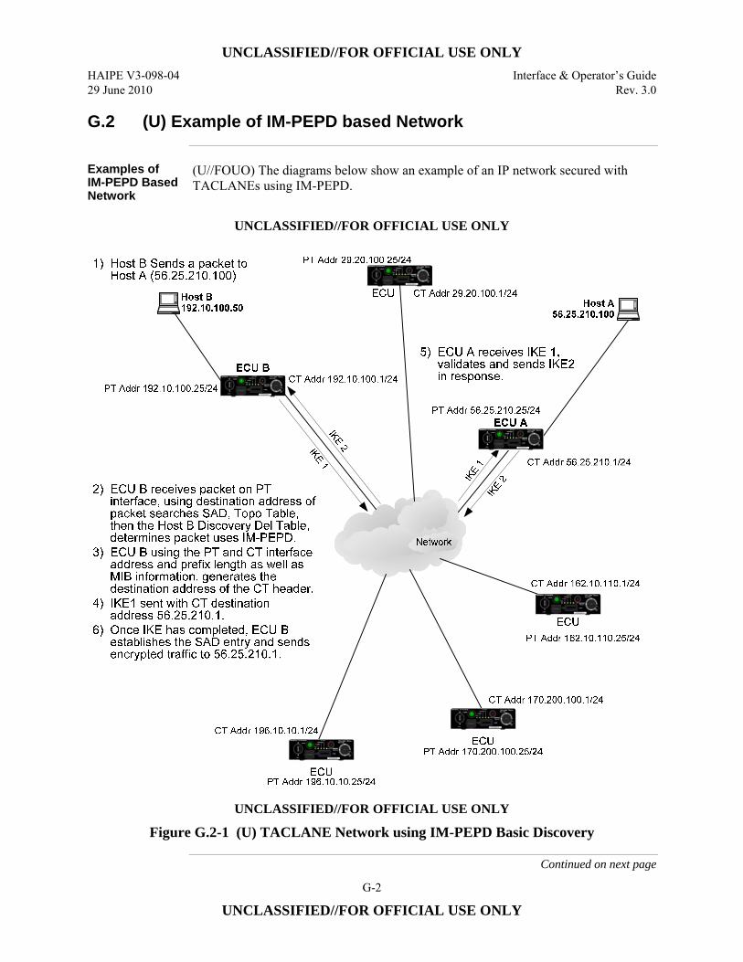
UNCLASSIFIED//FOR OFFICIAL USE ONLY
HAIPE V3-098-04 Interface & Operator’s Guide 29 June 2010 Rev. 3.0
G-2
UNCLASSIFIED//FOR OFFICIAL USE ONLY
G.2 (U) Example of IM-PEPD based Network
Examples of IM-PEPD Based Network
(U//FOUO) The diagrams below show an example of an IP network secured with TACLANEs using IM-PEPD.
UNCLASSIFIED//FOR OFFICIAL USE ONLY
UNCLASSIFIED//FOR OFFICIAL USE ONLY
Figure G.2-1 (U) TACLANE Network using IM-PEPD Basic Discovery
Continued on next page
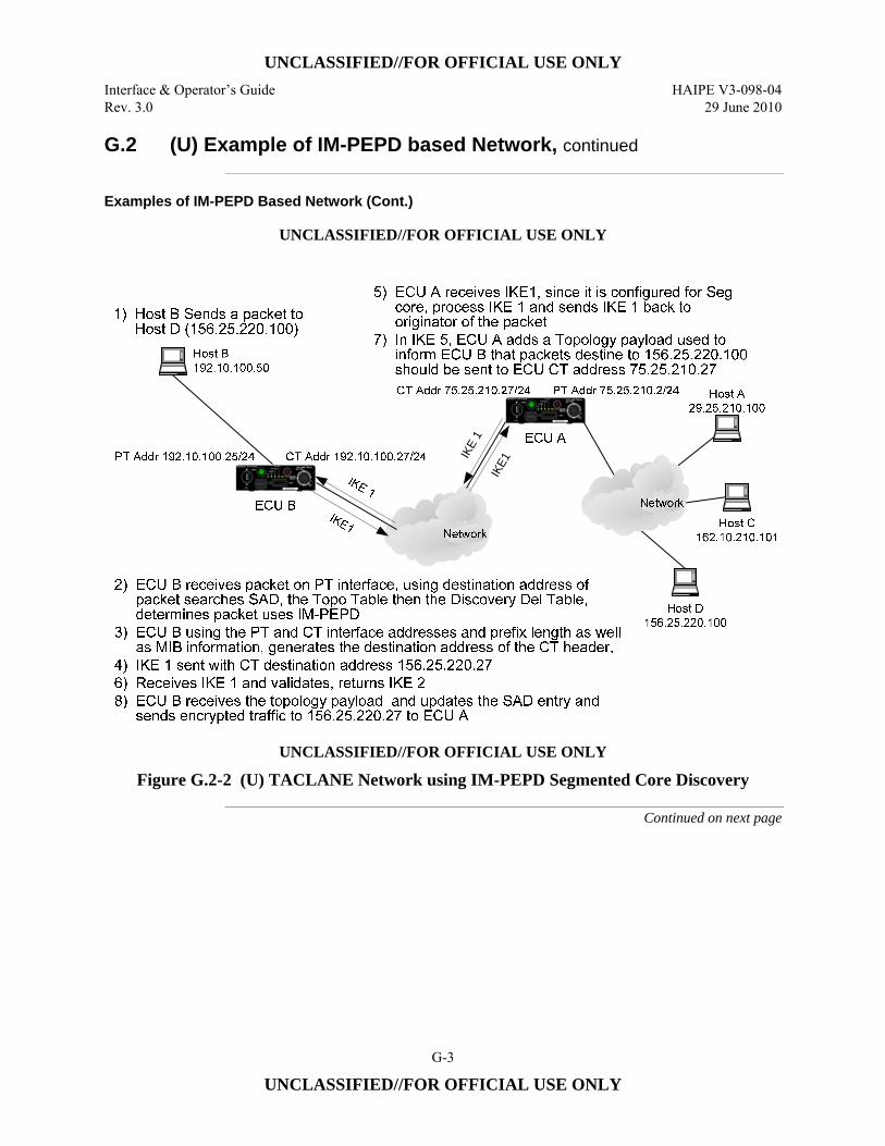
UNCLASSIFIED//FOR OFFICIAL USE ONLY
Interface & Operator’s Guide HAIPE V3-098-04 Rev. 3.0 29 June 2010
G-3
UNCLASSIFIED//FOR OFFICIAL USE ONLY
G.2 (U) Example of IM-PEPD based Network, continued
Examples of IM-PEPD Based Network (Cont.)
UNCLASSIFIED//FOR OFFICIAL USE ONLY
IKE
1IK
E1
UNCLASSIFIED//FOR OFFICIAL USE ONLY
Figure G.2-2 (U) TACLANE Network using IM-PEPD Segmented Core Discovery
Continued on next page
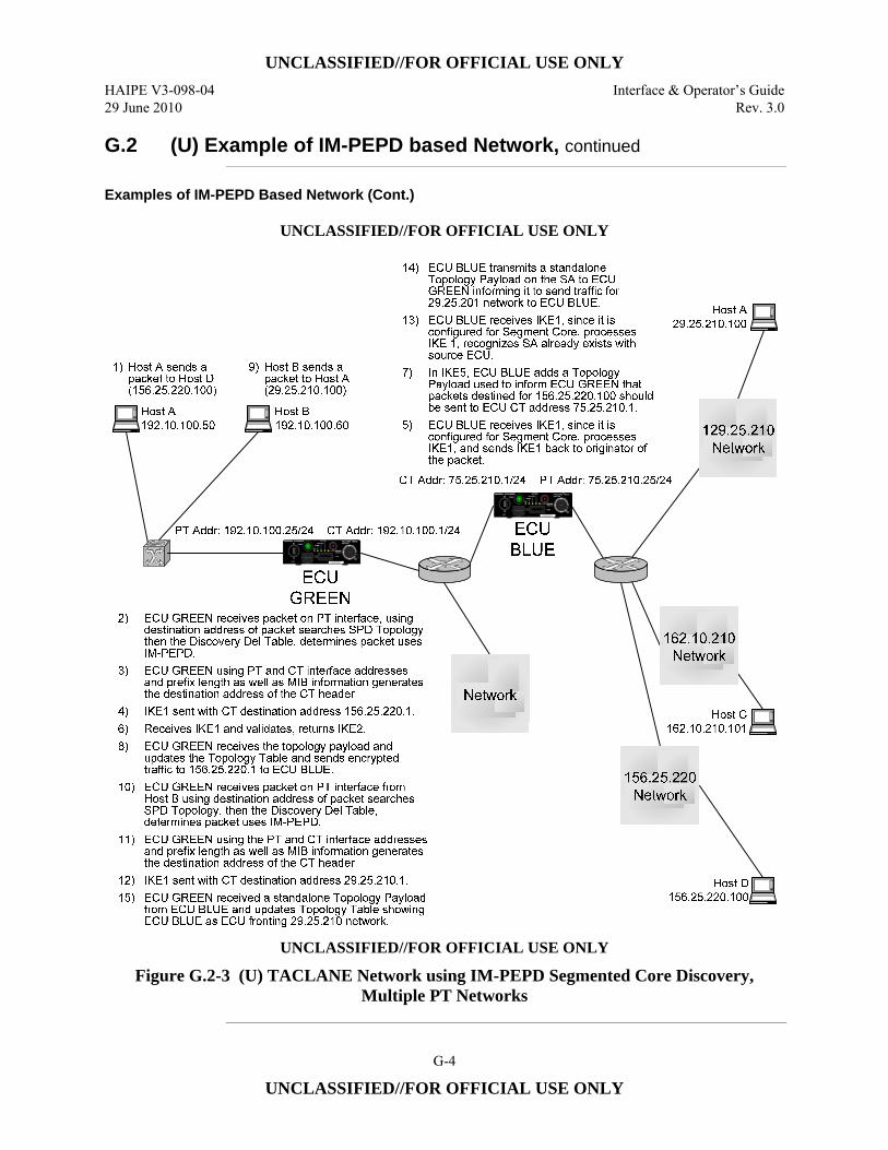
UNCLASSIFIED//FOR OFFICIAL USE ONLY
HAIPE V3-098-04 Interface & Operator’s Guide 29 June 2010 Rev. 3.0
G-4
UNCLASSIFIED//FOR OFFICIAL USE ONLY
G.2 (U) Example of IM-PEPD based Network, continued
Examples of IM-PEPD Based Network (Cont.)
UNCLASSIFIED//FOR OFFICIAL USE ONLY
UNCLASSIFIED//FOR OFFICIAL USE ONLY
Figure G.2-3 (U) TACLANE Network using IM-PEPD Segmented Core Discovery, Multiple PT Networks
UNCLASSIFIED//FOR OFFICIAL USE ONLY
Interface & Operator’s Guide HAIPE V3-098-04 Rev. 3.0 29 June 2010
G-5
UNCLASSIFIED//FOR OFFICIAL USE ONLY
G.3 (U) IM-PEPD Configuration Tips
Introduction (U//FOUO) Listed below are some general TACLANE IM-PEPD configuration tips.
Basis Steps to Configure GDC
(U//FOUO) To configure a TACLANE for IM-PEPD, the following steps must be taken: 1. (U//FOUO) Configure a Discovery Delivery Server with protocol type = IM-
PEPD. 2. (U//FOUO) Configure IP addresses for the PT and CT interfaces. The PT and
CT addresses must have the same prefix. For Segmented Core mode of operation, the CT IP interface needs this enabled.
3. (U//FOUO) Fill a FFVS, create a FF Template, and configure CT inbound and outbound SPD Protect rules to allow communication with the remote ECU(s) of interest.
Continued on Next Page
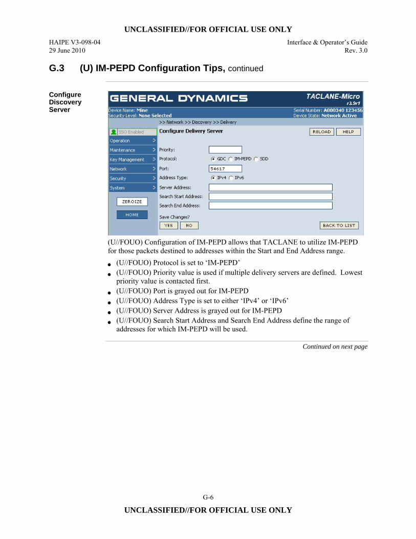
UNCLASSIFIED//FOR OFFICIAL USE ONLY
HAIPE V3-098-04 Interface & Operator’s Guide 29 June 2010 Rev. 3.0
G-6
UNCLASSIFIED//FOR OFFICIAL USE ONLY
G.3 (U) IM-PEPD Configuration Tips, continued
Configure Discovery Server
(U//FOUO) Configuration of IM-PEPD allows that TACLANE to utilize IM-PEPD for those packets destined to addresses within the Start and End Address range.
• (U//FOUO) Protocol is set to ‘IM-PEPD’ • (U//FOUO) Priority value is used if multiple delivery servers are defined. Lowest
priority value is contacted first. • (U//FOUO) Port is grayed out for IM-PEPD • (U//FOUO) Address Type is set to either ‘IPv4’ or ‘IPv6’ • (U//FOUO) Server Address is grayed out for IM-PEPD • (U//FOUO) Search Start Address and Search End Address define the range of
addresses for which IM-PEPD will be used.
Continued on next page
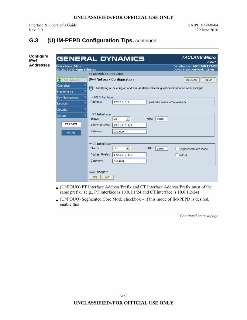
UNCLASSIFIED//FOR OFFICIAL USE ONLY
Interface & Operator’s Guide HAIPE V3-098-04 Rev. 3.0 29 June 2010
G-7
UNCLASSIFIED//FOR OFFICIAL USE ONLY
G.3 (U) IM-PEPD Configuration Tips, continued
Configure IPv4 Addresses
• (U//FOUO) PT Interface Address/Prefix and CT Interface Address/Prefix must of the same prefix. (e.g., PT interface is 10.0.1.1/24 and CT interface is 10.0.1.2/24)
• (U//FOUO) Segmented Core Mode checkbox – if this mode of IM-PEPD is desired, enable this
Continued on next page
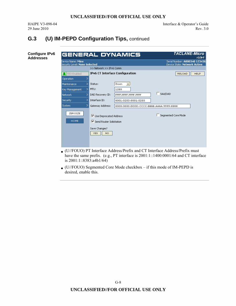
UNCLASSIFIED//FOR OFFICIAL USE ONLY
HAIPE V3-098-04 Interface & Operator’s Guide 29 June 2010 Rev. 3.0
G-8
UNCLASSIFIED//FOR OFFICIAL USE ONLY
G.3 (U) IM-PEPD Configuration Tips, continued
Configure IPv6 Addresses
• (U//FOUO) PT Interface Address/Prefix and CT Interface Address/Prefix must
have the same prefix. (e.g., PT interface is 2001:1::1400:0001/64 and CT interface is 2001:1::8383:a4b1/64)
• (U//FOUO) Segmented Core Mode checkbox – if this mode of IM-PEPD is desired, enable this.