tactical storesinformation 2 manual pocketguide · 2 days ago ·...
TRANSCRIPT

TACTICALMANUAL
POCKET GUIDE
F/A-18A/B/C/DAIRCRAFT
THIS PUBLICATION SUPERSEDES NWP5-55-F/A-18 PG (REV. C) (A1-F18AC-TAC-300) DATED SEPTEMBER 1994 WITHCHANGE 4 DATED SEPTEMBER 1998.
DISTRIBUTION STATEMENT C.Distribution authorized to U. S. Governmentagencies and their contractors December 1990.
DESTRUCTION NOTICE. Destroy by anymethod that will prevent disclosure of contentsor reconstruction of the document.
ISSUED BY AUTHORITY OF THE CHIEFOF THE NAVAL OPERATIONS ANDUNDER THE DIRECTION OF THECOMMANDER, OPERATIONAL TEST ANDEVALUATION FORCE
COMBAT CHECKS 1
STORES INFORMATION 2
AIR-TO-AIR WEAPONS 3
AIR-TO-GROUNDWEAPONS
4
AIR-TO-GROUNDMISSILES
5
ECM EQUIPMENT 6
FUZE INSPECTIONS 7
NWP 3-22.5-FA18A/B/C/DPG (Rev. A)
A1-F18AC-TAC-300
AUGUST 2001
NWP 3-22.5-FA18A/B/C/D PG(Rev. A)
A1-F18AC-TAC-300/(U)
TACTICAL MANUALPOCKET GUIDE
F/A-18A/B/C/DAIRCRAFT
THIS PUBLICATION SUPERSEDES NWP 55-5-F/A18 PG(REV. C) (A1-F18AC-TAC-300) DATED SEPTEMBER 1994WITH CHANGE 4 DATED SEPTEMBER 1998.
THIS PUBLICATION IS REQUIRED FOR OFFICIAL USEOR FOR ADMINISTRATIVE OR OPERATIONALPURPOSES ONLY. DISTRIBUTION IS LIMITED TO U.S.GOVERNMENT AGENCIES. OTHER REQUESTS FOR THEDOCUMENT MUST BE REFERRED TO CHIEF OF NAVALOPERATIONS (N880), WASHINGTON DC 20350-2000.
DISTRIBUTION STATEMENT C. Distribution authorized toU. S. Government agencies and their contractors December 1990.
DESTRUCTION NOTICE. Destroy by any method that willprevent disclosure of contents or reconstruction of the document.
ISSUED BY AUTHORITY OF THE CHIEF OF NAVALOPERATIONS AND UNDER THE DIRECTION OFTHE COMMANDER, OPERATIONAL TEST AND
EVALUATION FORCE.
AUGUST 2001
Reproduction for nonmilitary use of the information or illustrations contained in
this publication is not permitted without specific approval of the Commander,
Naval Air Systems Commands. The policy for use of classified publications is
established for the Navy and Marine Corps in OPNAVIST 5510.1 series.
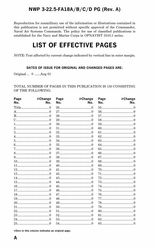
LIST OF EFFECTIVE PAGES
NOTE: Text affected by current change indicated by vertical line in outer margin.
DATES OF ISSUE FOR ORIGINAL AND CHANGED PAGES ARE:
Original ... 0 .......Aug 01
TOTAL NUMBER OF PAGES IN THIS PUBLICATION IS 150 CONSISTING
OF THE FOLLOWING:
Page #Change Page #Change Page #ChangeNo. No. No. No. No. No.
Title ................................0
A......................................0
B......................................0
C......................................0
1.......................................0
2.......................................0
3.......................................0
4.......................................0
5.......................................0
6.......................................0
7.......................................0
8.......................................0
9.......................................0
10.....................................0
11.....................................0
12.....................................0
13.....................................0
14.....................................0
15.....................................0
16.....................................0
17.....................................0
18.....................................0
19.....................................0
20.....................................0
21.....................................0
22.....................................0
23.....................................0
24.....................................0
25.....................................0
26.....................................0
27.....................................0
28.....................................0
29.....................................0
30.....................................0
31.....................................0
32.....................................0
33.....................................0
34.....................................0
35.....................................0
36.....................................0
37.....................................0
38.....................................0
39.....................................0
40.....................................0
41.....................................0
42.....................................0
43.....................................0
44.....................................0
45.....................................0
46.....................................0
47.....................................0
48.....................................0
49.....................................0
50.....................................0
51.....................................0
52.....................................0
53.....................................0
54.....................................0
55.....................................0
56.....................................0
57.....................................0
58.....................................0
59.....................................0
60.....................................0
61.....................................0
62.....................................0
63.....................................0
64.....................................0
65.....................................0
66.....................................0
67.....................................0
68.....................................0
69.....................................0
70.....................................0
71.....................................0
72.....................................0
73.....................................0
74.....................................0
75.....................................0
76.....................................0
77.....................................0
78.....................................0
79.....................................0
80.....................................0
81.....................................0
82.....................................0
83.....................................0
NWP 3-22.5-FA18A/B/C/D PG (Rev. A)
#Zero in this column indicates an original page.
A

84.....................................0
85.....................................0
86.....................................0
87.....................................0
88.....................................0
89 blank .........................0
90.....................................0
91.....................................0
92.....................................0
93.....................................0
94.....................................0
95.....................................0
96.....................................0
97.....................................0
98.....................................0
99.....................................0
100...................................0
101...................................0
102...................................0
103...................................0
104...................................0
105...................................0
106...................................0
107...................................0
108...................................0
109...................................0
110...................................0
111...................................0
112...................................0
113...................................0
114...................................0
115...................................0
116...................................0
117...................................0
118...................................0
119...................................0
120...................................0
121...................................0
122...................................0
123...................................0
124...................................0
125...................................0
126...................................0
127...................................0
128...................................0
129...................................0
130...................................0
131...................................0
132...................................0
133...................................0
134...................................0
135 blank .......................0
136...................................0
137...................................0
138...................................0
139...................................0
140...................................0
141...................................0
142 blank .......................0
143...................................0
144...................................0
145...................................0
146 blank .......................0
NWP 3-22.5-FA18A/B/C/D PG (Rev. A)Page #Change Page #Change Page #ChangeNo. No. No. No. No. No.
#Zero in this column indicates an original page.
B
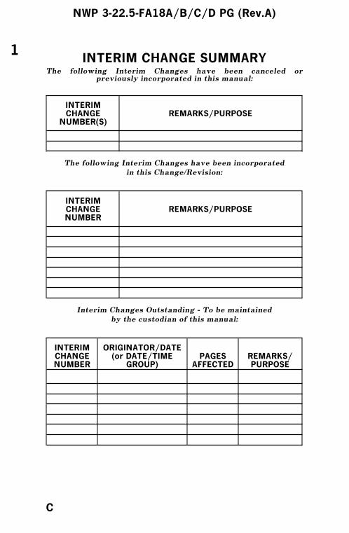
INTERIM CHANGE SUMMARYThe following Interim Changes have been canceled or
previously incorporated in this manual:
INTERIMCHANGE
NUMBER(S)REMARKS/PURPOSE
The following Interim Changes have been incorporated
in this Change/Revision:
INTERIMCHANGENUMBER
REMARKS/PURPOSE
Interim Changes Outstanding - To be maintained
by the custodian of this manual:
INTERIMCHANGENUMBER
ORIGINATOR/DATE(or DATE/TIME
GROUP)PAGES
AFFECTEDREMARKS/PURPOSE
1
NWP 3-22.5-FA18A/B/C/D PG (Rev.A)
C

COMBAT CHECKS
PREFLIGHT
1. SMP set2. ALE-39 loadout/settings reset3. VTR tape4. Mode II check5. IFF DIS/AUD/IR COOL
GROUND
1. WYPTS/SEQ/A-A WYPT2. NCTR / RALT / BALT3. Radar Attack - DCLTR/CHAN/SETS/(training)4. AZ/EL5. SMS
a. (SIM)b. Gunc. SP tune/AM testd. A/G PROGe. WPN SELf. ◊
6. Smart weapons checks7. Time - SET8. FLIR - STBY
AIRBORNE
1. Cycle A/G - Racks unlock2. ALR-67/ALQ/FLIR - ON3. Check Radar - CHAN/(SIM)/SETS/CAL4. Bingo Bug - SET5. ALQ/ALR - BIT6. ACM modes/AIM-9/FLIR
NWP 3-22.5-FA18A/B/C/D PG (Rev. A)
1
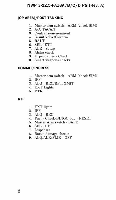
(OP AREA)/POST TANKING
1. Master arm switch - ARM (check SIM)2. A/A TACAN3. Contrails/environment4. G-suit/valve/G-warm5. RALT6. SEL JETT7. ALE - Setup8. Alpha check9. Expendables - Check10. Smart weapons checks
COMMIT/INGRESS
1. Master arm switch - ARM (check SIM)2. IFF3. ALQ - REC/RPT/XMIT4. EXT Lights5. VTR
RTF
1. EXT lights2. IFF3. ALQ - REC4. Fuel - Check/BINGO bug - RESET5. Master Arm switch - SAFE6. SEL JETT7. Dispenser8. Battle damage checks9. ALQ/ALR/FLIR - OFF
NWP 3-22.5-FA18A/B/C/D PG (Rev. A)
2
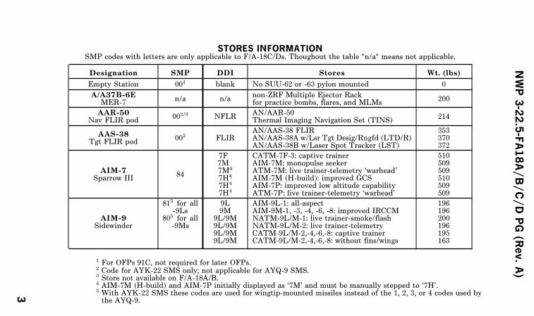
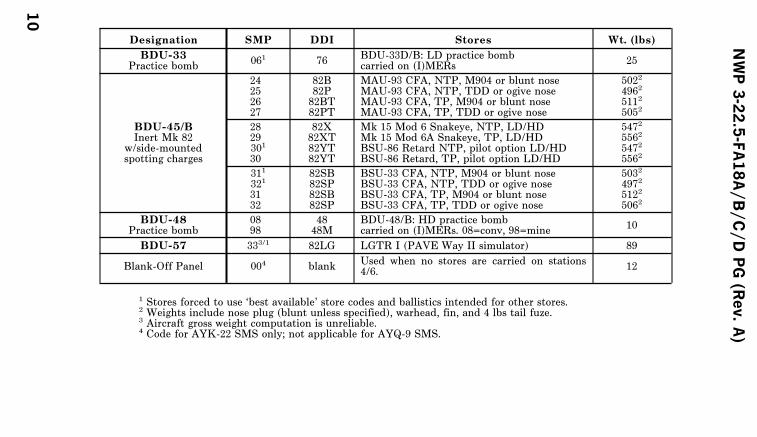
STORES INFORMATIONSMP codes with letters are only applicable to F/A-18C/Ds. Thoughout the table ″n/a″ means not applicable.
Designation SMP DDI Stores Wt. (lbs)
Empty Station 001 blank No SUU-62 or -63 pylon mounted 0
A/A37B-6EMER-7
n/a n/anon-ZRF Multiple Ejector Rackfor practice bombs, flares, and MLMs
200
AAR-50Nav FLIR pod
002/3 NFLRAN/AAR-50Thermal Imaging Navigation Set (TINS)
214
AAS-38Tgt FLIR pod
002 FLIRAN/AAS-38 FLIRAN/AAS-38A w/Lsr Tgt Desig/Rngfd (LTD/R)AN/AAS-38B w/Laser Spot Tracker (LST)
353370372
AIM-7Sparrow III
84
7F7M7M4
7H4
7H4
7H4
CATM-7F-3: captive trainerAIM-7M: monopulse seekerATM-7M: live trainer-telemetry ‘warhead’AIM-7M (H-build): improved GCSAIM-7P: improved low altitude capabilityATM-7P: live trainer-telemetry ‘warhead’
510509509510509509
AIM-9Sidewinder
815 for all-9Ls
805 for all-9Ms
9L9M
9L/9M9L/9M9L/9M9L/9M
AIM-9L-1: all-aspectAIM-9M-1, -3, -4, -6, -8: improved IRCCMNATM-9L/M-1: live trainer-smoke/flashNATM-9L/M-2: live trainer-telemetryCATM-9L/M-2,-4,-6,-8: captive trainerCATM-9L/M-2,-4,-6,-8: without fins/wings
196196200196195163
1 For OFPs 91C, not required for later OFPs.2 Code for AYK-22 SMS only; not applicable for AYQ-9 SMS.3 Store not available on F/A-18A/B.4 AIM-7M (H-build) and AIM-7P initially displayed as ‘7M’ and must be manually stepped to ‘7H’.5 With AYK-22 SMS these codes are used for wingtip-mounted missiles instead of the 1, 2, 3, or 4 codes used bythe AYQ-9.
NWP3-22.5-FA18A/B/C/DPG(Rev.A)
3
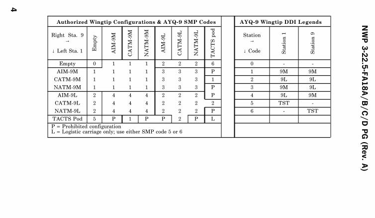
Authorized Wingtip Configurations & AYQ-9 SMP Codes AYQ-9 Wingtip DDI Legends
Right Sta. 9→
↓ Left Sta. 1 Empty
AIM
-9M
CATM-9M
NATM-9M
AIM
-9L
CATM-9L
NATM-9L
TACTSpod
Station→
↓ Code Station1
Station9
Empty 0 1 1 1 2 2 2 6 0 - -
AIM-9M 1 1 1 1 3 3 3 P 1 9M 9M
CATM-9M 1 1 1 1 3 3 3 1 2 9L 9L
NATM-9M 1 1 1 1 3 3 3 P 3 9M 9L
AIM-9L 2 4 4 4 2 2 2 P 4 9L 9M
CATM-9L 2 4 4 4 2 2 2 2 5 TST -
NATM-9L 2 4 4 4 2 2 2 P 6 - TST
TACTS Pod 5 P 1 P P 2 P L
P = Prohibited configurationL = Logistic carriage only; use either SMP code 5 or 6
NWP3-22.5-FA18A/B/C/DPG(Rev.A)
4

During simulated training (weapons notloaded), closing the hooks of BRU-32/A orVER (BRU-33/A) on outboard pylons isprohibited, when codes for weapons listedbelow and an AIM-9 wingtip code areentered on the armament computer.
Mk 83 GBU-16 AGM-84EMk 84 GBU-10 AGM-88Mk 40 GBU-24 Mk 55Mk 41 LAU-10Mk 63Mk 64Mk 65
NWP3-22.5-FA18A/B/C/DPG(Rev.A)
5

Designation SMP DDI Stores Wt. (lbs)
Walleye I1,000 lb
EO-Guided Bomb69
WEDLWEDLWEDL
Mk 21 ER/DL, Phase IMk 29 ER/DL, Phase IIMk 34 ER/DL, Phase II Haze Penetrator
1,2241,2241,224
Walleye II2,000 lb EOGB
691WEDLWEDLWEDL
Mk 23 ER/DL, Phase IMk 30 ER/DL, Phase IIMk 37 ER/DL, Phase II Haze Penetrator
2,4152,4152,415
Walleye PracticeGuided Weapon
(PGW)(without wings)
69WEDLWEDLWEDL
Mk 27 cap. DL, Phase IMk 38 cap. DL, Phase I Haze PenetratorMk 39 cap. DL, Phase II Haze Penetrator
1,1301,1301,130
AGM-65Maverick
65MAVMAV
AGM-65E: Laser GuidedA/A37A-T9: TGM-65E: captive laser trainer
642642
662MAVFMAVF
AGM-65F: imaging infrared guidedCATM-65F: cap IIR trainer
669669
AGM-84DHarpoon
62 HPD AGM-84D: Block 1C 1,2213
63THPDTHPDTHP
ATM-84D-1: exercise-telemetry ‘warhead’ATM-84D-1A: exercise-inert warheadCATM-84D-1: inert captive trainer
1,2133
1,2213
1,151
1 Aircraft gross weight computation and ‘in range’ cues are unreliable.2 Not available with F/A-18A/B.3 Missiles fueled with JP10; those fueled with JP5 weigh 20 lbs less.
NWP3-22.5-FA18A/B/C/DPG(Rev.A)
6

Designation SMP DDI Stores Wt. (lbs)
AGM-84ESLAM
67 SLAM AGM-84E Standoff Land Attack Missile 1,366
70TSLMTSLM
ATM-84E-1C: exercise-telemetry ‘warhead’CATM-84E-1C: captive trainer
1,3601,360
AGM-84HSLAM ER
F0 SLMR SLAM ER: CATM/Tactical 1480
F0F0
TSLRDL13
SLAM ER: telemetryAWW-13
1484707
AGM-88HARM
64 HARM
AGM-88A: Block II seekersCATM-88A: captive trainer
800AGM-88B: Block II & III seekersATM-88B: live trainer, inert warheadCATM-88B: captive trainer
AGM-88C: Block IV seekers1
CATM-88C: captive trainer
AIM-120AMRAAM
F02AM/AA3 AIM-120A, Adv. Med. Rng. Air-to-Air Msl. 347
AM/AB3 AIM-120B (production improvements) 347
AM/AC3 AIM-120C (compressed carriage) 345
ADM-141TALD
25482P82P
ADM-141A: active/passive RF aug.ADM-141B: chaff dispensing
400382
AGM-154AJSOW
F02
F02
915
JSATJSA52
AGM-154A: 145 x BLU-97A/B CEMCATM-154A: Captive Flight Vehicle (CFV)
10301030
1 Not available with F/A-18A/B.2 NAWCWD-installed telemetry (TM) sections authorized.3 Codes on the left are for OFP 91C, those on the right are for OFP 11C and later.4 Stores forced to use ‘best available’ store codes and ballistics intended for other stores.5 For logistic carriage of AGM or CATM-154 when the MIL-STD-1760 umbilical is not connected.
NWP3-22.5-FA18A/B/C/DPG(Rev.A)
7
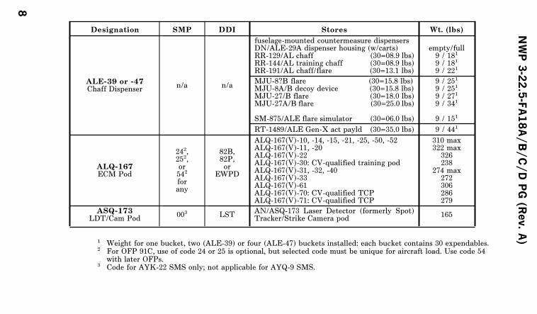
Designation SMP DDI Stores Wt. (lbs)
ALE-39 or -47Chaff Dispenser
n/a n/a
fuselage-mounted countermeasure dispensersDN/ALE-29A dispenser housing (w/carts)RR-129/AL chaff (30=08.9 lbs)RR-144/AL training chaff (30=08.9 lbs)RR-191/AL chaff/flare (30=13.1 lbs)
empty/full9 / 181
9 / 181
9 / 221
MJU-8?B flare (30=15.8 lbs)MJU-8A/B decoy device (30=15.8 lbs)MJU-27/B flare (30=18.0 lbs)MJU-27A/B flare (30=25.0 lbs)
SM-875/ALE flare simulator (30=06.0 lbs)
9 / 251
9 / 251
9 / 271
9 / 341
9 / 151
RT-1489/ALE Gen-X act payld (30=35.0 lbs) 9 / 441
ALQ-167ECM Pod
242,252,or542
forany
82B,82P,or
EWPD
ALQ-167(V)-10, -14, -15, -21, -25, -50, -52ALQ-167(V)-11, -20ALQ-167(V)-22ALQ-167(V)-30: CV-qualified training podALQ-167(V)-31, -32, -40ALQ-167(V)-33ALQ-167(V)-61ALQ-167(V)-70: CV-qualified TCPALQ-167(V)-71: CV-qualified TCP
310 max322 max
326238
274 max272306286279
ASQ-173LDT/Cam Pod
003 LSTAN/ASQ-173 Laser Detector (formerly Spot)Tracker/Strike Camera pod
165
1 Weight for one bucket, two (ALE-39) or four (ALE-47) buckets installed: each bucket contains 30 expendables.2 For OFP 91C, use of code 24 or 25 is optional, but selected code must be unique for aircraft load. Use code 54
with later OFPs.3 Code for AYK-22 SMS only; not applicable for AYQ-9 SMS.
NWP3-22.5-FA18A/B/C/DPG(Rev.A)
8
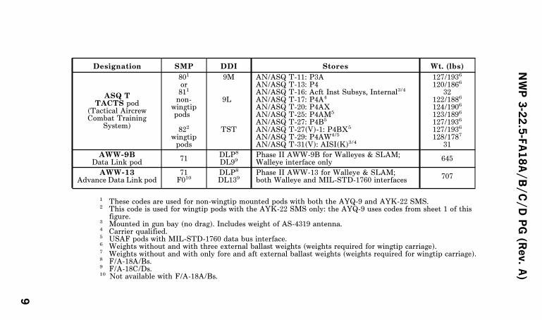
Designation SMP DDI Stores Wt. (lbs)
ASQ TTACTS pod
(Tactical AircrewCombat Training
System)
801
or811
non-wingtippods
822
wingtippods
9M
9L
TST
AN/ASQ T-11: P3AAN/ASQ T-13: P4AN/ASQ T-16: Acft Inst Subsys, Internal3/4
AN/ASQ T-17: P4A4
AN/ASQ T-20: P4AXAN/ASQ T-25: P4AM5
AN/ASQ T-27: P4B5
AN/ASQ T-27(V)-1: P4BX5
AN/ASQ T-29: P4AW4/5
AN/ASQ T-31(V): AISI(K)3/4
127/1936
120/1866
32122/1886
124/1906
123/1896
127/1936
127/1936
128/1787
31
AWW-9BData Link pod
71DLP8
DL99Phase II AWW-9B for Walleyes & SLAM;Walleye interface only
645
AWW-13Advance Data Link pod
71F010
DLP8
DL139Phase II AWW-13 for Walleye & SLAM;both Walleye and MIL-STD-1760 interfaces
707
1 These codes are used for non-wingtip mounted pods with both the AYQ-9 and AYK-22 SMS.2 This code is used for wingtip pods with the AYK-22 SMS only: the AYQ-9 uses codes from sheet 1 of this
figure.3 Mounted in gun bay (no drag). Includes weight of AS-4319 antenna.4 Carrier qualified.5 USAF pods with MIL-STD-1760 data bus interface.6 Weights without and with three external ballast weights (weights required for wingtip carriage).7 Weights without and with only fore and aft external ballast weights (weights required for wingtip carriage).8 F/A-18A/Bs.9 F/A-18C/Ds.10 Not available with F/A-18A/Bs.
NWP3-22.5-FA18A/B/C/DPG(Rev.A)
9
Designation SMP DDI Stores Wt. (lbs)
BDU-33Practice bomb
061 76BDU-33D/B: LD practice bombcarried on (I)MERs
25
BDU-45/BInert Mk 82
w/side-mountedspotting charges
24252627
82B82P82BT82PT
MAU-93 CFA, NTP, M904 or blunt noseMAU-93 CFA, NTP, TDD or ogive noseMAU-93 CFA, TP, M904 or blunt noseMAU-93 CFA, TP, TDD or ogive nose
5022
4962
5112
5052
2829301
30
82X82XT82YT82YT
Mk 15 Mod 6 Snakeye, NTP, LD/HDMk 15 Mod 6A Snakeye, TP, LD/HDBSU-86 Retard NTP, pilot option LD/HDBSU-86 Retard, TP, pilot option LD/HD
5472
5562
5472
5562
311
321
3132
82SB82SP82SB82SP
BSU-33 CFA, NTP, M904 or blunt noseBSU-33 CFA, NTP, TDD or ogive noseBSU-33 CFA, TP, M904 or blunt noseBSU-33 CFA, TP, TDD or ogive nose
5032
4972
5122
5062
BDU-48Practice bomb
0898
4848M
BDU-48/B: HD practice bombcarried on (I)MERs. 08=conv, 98=mine
10
BDU-57 333/1 82LG LGTR I (PAVE Way II simulator) 89
Blank-Off Panel 004 blankUsed when no stores are carried on stations4/6.
12
1 Stores forced to use ‘best available’ store codes and ballistics intended for other stores.2 Weights include nose plug (blunt unless specified), warhead, fin, and 4 lbs tail fuze.3 Aircraft gross weight computation is unreliable.4 Code for AYK-22 SMS only; not applicable for AYQ-9 SMS.
NWP3-22.5-FA18A/B/C/DPG(Rev.A)
10
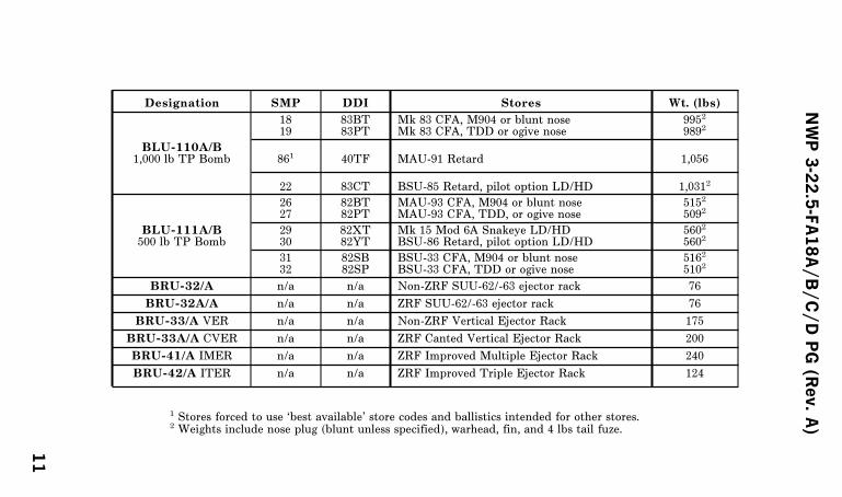
Designation SMP DDI Stores Wt. (lbs)
BLU-110A/B1,000 lb TP Bomb
1819
83BT83PT
Mk 83 CFA, M904 or blunt noseMk 83 CFA, TDD or ogive nose
9952
9892
861 40TF MAU-91 Retard 1,056
22 83CT BSU-85 Retard, pilot option LD/HD 1,0312
BLU-111A/B500 lb TP Bomb
2627
82BT82PT
MAU-93 CFA, M904 or blunt noseMAU-93 CFA, TDD, or ogive nose
5152
5092
2930
82XT82YT
Mk 15 Mod 6A Snakeye LD/HDBSU-86 Retard, pilot option LD/HD
5602
5602
3132
82SB82SP
BSU-33 CFA, M904 or blunt noseBSU-33 CFA, TDD or ogive nose
5162
5102
BRU-32/A n/a n/a Non-ZRF SUU-62/-63 ejector rack 76
BRU-32A/A n/a n/a ZRF SUU-62/-63 ejector rack 76
BRU-33/A VER n/a n/a Non-ZRF Vertical Ejector Rack 175
BRU-33A/A CVER n/a n/a ZRF Canted Vertical Ejector Rack 200
BRU-41/A IMER n/a n/a ZRF Improved Multiple Ejector Rack 240
BRU-42/A ITER n/a n/a ZRF Improved Triple Ejector Rack 124
1 Stores forced to use ‘best available’ store codes and ballistics intended for other stores.2 Weights include nose plug (blunt unless specified), warhead, fin, and 4 lbs tail fuze.
NWP3-22.5-FA18A/B/C/DPG(Rev.A)
11
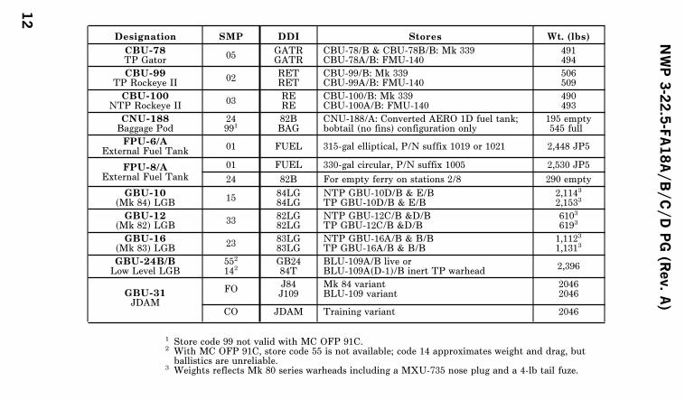
Designation SMP DDI Stores Wt. (lbs)
CBU-78TP Gator
05GATRGATR
CBU-78/B & CBU-78B/B: Mk 339CBU-78A/B: FMU-140
491494
CBU-99TP Rockeye II
02RETRET
CBU-99/B: Mk 339CBU-99A/B: FMU-140
506509
CBU-100NTP Rockeye II
03RERE
CBU-100/B: Mk 339CBU-100A/B: FMU-140
490493
CNU-188Baggage Pod
24991
82BBAG
CNU-188/A: Converted AERO 1D fuel tank;bobtail (no fins) configuration only
195 empty545 full
FPU-6/AExternal Fuel Tank
01 FUEL 315-gal elliptical, P/N suffix 1019 or 1021 2,448 JP5
FPU-8/AExternal Fuel Tank
01 FUEL 330-gal circular, P/N suffix 1005 2,530 JP5
24 82B For empty ferry on stations 2/8 290 empty
GBU-10(Mk 84) LGB
1584LG84LG
NTP GBU-10D/B & E/BTP GBU-10D/B & E/B
2,1143
2,1533
GBU-12(Mk 82) LGB
3382LG82LG
NTP GBU-12C/B &D/BTP GBU-12C/B &D/B
6103
6193
GBU-16(Mk 83) LGB
2383LG83LG
NTP GBU-16A/B & B/BTP GBU-16A/B & B/B
1,1123
1,1313
GBU-24B/BLow Level LGB
552
142GB2484T
BLU-109A/B live orBLU-109A(D-1)/B inert TP warhead
2,396
GBU-31JDAM
FOJ84J109
Mk 84 variantBLU-109 variant
20462046
CO JDAM Training variant 2046
1 Store code 99 not valid with MC OFP 91C.2 With MC OFP 91C, store code 55 is not available; code 14 approximates weight and drag, butballistics are unreliable.
3 Weights reflects Mk 80 series warheads including a MXU-735 nose plug and a 4-lb tail fuze.
NWP3-22.5-FA18A/B/C/DPG(Rev.A)
12
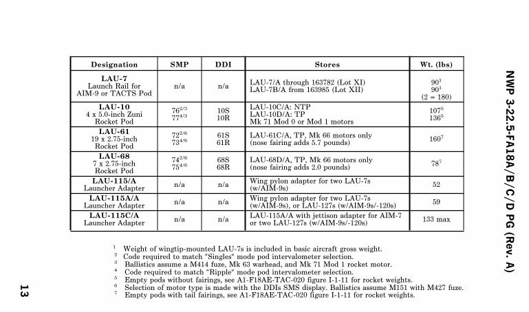
Designation SMP DDI Stores Wt. (lbs)
LAU-7Launch Rail for
AIM-9 or TACTS Podn/a n/a
LAU-7/A through 163782 (Lot XI)LAU-7B/A from 163985 (Lot XII)
901
901
(2 = 180)
LAU-104 x 5.0-inch Zuni
Rocket Pod
762/3
774/310S10R
LAU-10C/A: NTPLAU-10D/A: TPMk 71 Mod 0 or Mod 1 motors
1075
1365
LAU-6119 x 2.75-inchRocket Pod
722/6
734/661S61R
LAU-61C/A, TP, Mk 66 motors only(nose fairing adds 5.7 pounds)
1607
LAU-687 x 2.75-inchRocket Pod
742/6
754/668S68R
LAU-68D/A, TP, Mk 66 motors only(nose fairing adds 2.0 pounds)
787
LAU-115/ALauncher Adapter
n/a n/aWing pylon adapter for two LAU-7s(w/AIM-9s)
52
LAU-115A/ALauncher Adapter
n/a n/aWing pylon adapter for two LAU-7s(w/AIM-9s), or LAU-127s (w/AIM-9s/-120s)
59
LAU-115C/ALauncher Adapter
n/a n/aLAU-115A/A with jettison adapter for AIM-7or two LAU-127s (w/AIM-9s/-120s)
133 max
1 Weight of wingtip-mounted LAU-7s is included in basic aircraft gross weight.2 Code required to match ″Singles″ mode pod intervalometer selection.3 Ballistics assume a M414 fuze, Mk 63 warhead, and Mk 71 Mod 1 rocket motor.4 Code required to match ″Ripple″ mode pod intervalometer selection.5 Empty pods without fairings, see A1-F18AE-TAC-020 figure I-1-11 for rocket weights.6 Selection of motor type is made with the DDIs SMS display. Ballistics assume M151 with M427 fuze.7 Empty pods with tail fairings, see A1-F18AE-TAC-020 figure I-1-11 for rocket weights.
NWP3-22.5-FA18A/B/C/DPG(Rev.A)
13
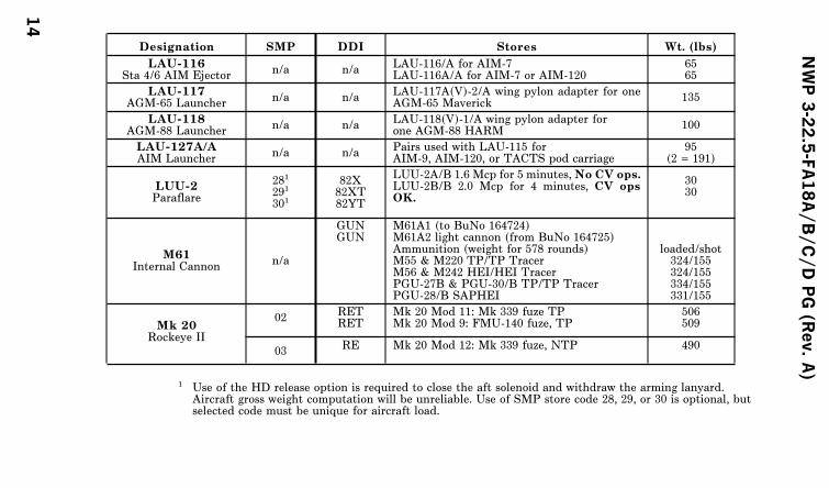
Designation SMP DDI Stores Wt. (lbs)
LAU-116Sta 4/6 AIM Ejector
n/a n/aLAU-116/A for AIM-7LAU-116A/A for AIM-7 or AIM-120
6565
LAU-117AGM-65 Launcher
n/a n/aLAU-117A(V)-2/A wing pylon adapter for oneAGM-65 Maverick
135
LAU-118AGM-88 Launcher
n/a n/aLAU-118(V)-1/A wing pylon adapter forone AGM-88 HARM
100
LAU-127A/AAIM Launcher
n/a n/aPairs used with LAU-115 forAIM-9, AIM-120, or TACTS pod carriage
95(2 = 191)
LUU-2Paraflare
281
291
301
82X82XT82YT
LUU-2A/B 1.6 Mcp for 5 minutes,No CV ops.LUU-2B/B 2.0 Mcp for 4 minutes, CV opsOK.
3030
M61Internal Cannon
n/a
GUNGUN
M61A1 (to BuNo 164724)M61A2 light cannon (from BuNo 164725)Ammunition (weight for 578 rounds)M55 & M220 TP/TP TracerM56 & M242 HEI/HEI TracerPGU-27B & PGU-30/B TP/TP TracerPGU-28/B SAPHEI
loaded/shot324/155324/155334/155331/155
Mk 20Rockeye II
02RETRET
Mk 20 Mod 11: Mk 339 fuze TPMk 20 Mod 9: FMU-140 fuze, TP
506509
03RE Mk 20 Mod 12: Mk 339 fuze, NTP 490
1 Use of the HD release option is required to close the aft solenoid and withdraw the arming lanyard.Aircraft gross weight computation will be unreliable. Use of SMP store code 28, 29, or 30 is optional, butselected code must be unique for aircraft load.
NWP3-22.5-FA18A/B/C/DPG(Rev.A)
14
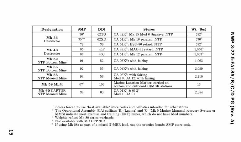
Designation SMP DDI Stores Wt. (lbs)
Mk 36Destructor
361 62TO OA 48K2: Mk 15 Mod 6 Snakeye, NTP 5523
351/4 62XO OA 51K2:: Mk 16 paratail, NTP 5363
78 36 OA 54K2:: BSU-86 retard, NTP 5523
Mk 40Destructor
85 40F OA 48K2:: MAU-91 retard, NTP 1,0563
87 40C OA 51K2:: Mk 12 paratail, NTP 1,0033
Mk 52NTP Bottom Mine
91 52 OA 05K2:: with fairing 1,063
Mk 55NTP Bottom Mine
92 55 OA 04K2:: with fairing 2,059
Mk 56NTP Moored Mine
93 56OA 06K3: with fairingMod 0, OA 12: with fairing
2,210
Mk 58 MLM 075 106Marine Location Marker: carried onbottom and outboard (I)MER stations
13
Mk 60 CAPTORNTP Moored Mine
34 60OA 01K3 & 01Q3
Mod 1. OA 012,354
1 Stores forced to use ″best available″ store codes and ballistics intended for other stores.2 The Operational Assembly (OA) suffixes ‘K’ (Laying) and ‘Q’ (Mk 5 Marine Mammal recovery System orMMS) indicate inert exercise and training (E&T) mines, which do not have Mod numbers.
3 Weights reflect Mk 80 series warheads.4 Not available with MC OFP 91C.5 If using Mk 58s as part of a mixed (I)MER load, use the practice bombs SMP store code.
NWP3-22.5-FA18A/B/C/DPG(Rev.A)
15
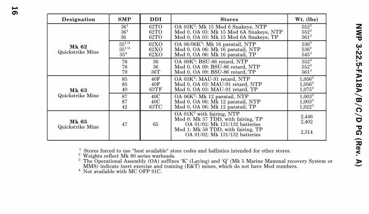
Designation SMP DDI Stores Wt. (lbs)
Mk 62Quickstrike Mine
361
361
36
62TO62TO62TO
OA 03K2: Mk 15 Mod 6 Snakeye, NTPMod 0, OA 03: Mk 15 Mod 6A Snakeye, NTPMod 0, OA 03: Mk 15 Mod 6A Snakeye, TP
5523
5523
5613
351/4
351/4
354
62XO62XO62XO
OA 06/06K2: Mk 16 paratail, NTPMod 0, OA 06: Mk 16 paratail, NTPMod 0, OA 06: Mk 16 paratail, TP
5363
5363
5453
787879
363636T
OA 09K2: BSU-86 retard, NTPMod 0, OA 09: BSU-86 retard, NTPMod 0, OA 09: BSU-86 retard, TP
5523
5523
5613
Mk 63Quickstrike Mine
858540
40F40F63TF
OA 03K2: MAU-91 retard, NTPMod 0, OA 03: MAU-91 retard, NTPMod 0, OA 03: MAU-91 retard, TP
1,0563
1,0563
1,0753
878742
40C40C63TC
OA 06K2: Mk 12 paratail, NTPMod 0, OA 06: Mk 12 paratail, NTPMod 0, OA 06: Mk 12 paratail, TP
1,0033
1,0033
1,0223
Mk 65Quickstrike Mine
47 65
OA 01K2 with fairing, NTPMod 0: Mk 57 TDD, with fairing, TP
OA 01/02: Mk 131/132 batteriesMod 1: Mk 58 TDD, with fairing, TP
OA 01/02: Mk 131/132 batteries
2,4462,402
2,314
1 Stores forced to use ″best available″ store codes and ballistics intended for other stores.2 Weights reflect Mk 80 series warheads.3 The Operational Assembly (OA) suffixes ‘K’ (Laying) and ‘Q’ (Mk 5 Marine Mammal recovery System orMMS) indicate inert exercise and training (E&T) mines, which do not have Mod numbers.
4 Not available with MC OFP 91C.
NWP3-22.5-FA18A/B/C/DPG(Rev.A)
16

Designation SMP DDI StoresWt. (lbs)
Mk 76Practice Bomb
06 76Mk 76 Mod 5: LD practice bombcarried on (I)MERs
25
Mk 77Fire Bomb
2121
7777
Mod 4: 71 gal of gelled AVGASMod 5: 43 lbs imbiber beads + 63 gal of jet fuel
520520
Mk 82500-lb Bomb(Mod 1: NTPMod 2: TP)
24252627
82B82P82BT82PT
MAU-93 CFA, NTP, M904 or blunt noseMAU-93 CFA, NTP, TDD or ogive noseMAU-93 CFA, TP, M904 or blunt noseMAU-93 CFA, TP, TDD or ogive nose
5131
5071
5221
5161
2829302
30
82X82XT82YT82YT
Mk 15 Mod 6 Snakeye, NTP, LD/HDMk 15 Mod 6A Snakeye, TP, LD/HDBSU-86 retard NTP, pilot option LD/HDBSU-86 retard, TP, pilot option LD/HD
5581
5671
5581
5671
312
322
3132
82SB82SP82SB82SP
BSU-33 CFA, NTP, M904 or blunt noseBSU-33 CFA, NTP, TDD or ogive noseBSU-33 CFA, TP, M904 or blunt noseBSU-33 CFA, TP TDD or ogive nose
5141
5081
5231
5171
1 Weights include nose plug (blunt unless specified otherwise), warhead, fin, and a 4-lbs tail fuze.2 Stores forced to use ‘best available’ store codes and ballistics intended for other stores.
NWP3-22.5-FA18A/B/C/DPG(Rev.A)
17
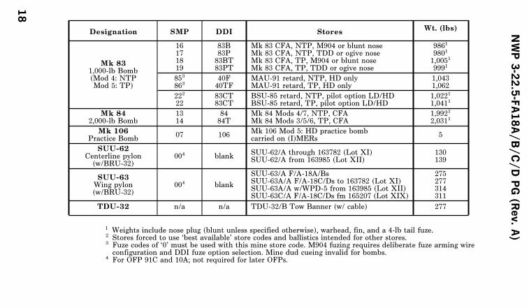
Designation SMP DDI StoresWt. (lbs)
Mk 831,000-lb Bomb(Mod 4: NTPMod 5: TP)
16171819
83B83P83BT83PT
Mk 83 CFA, NTP, M904 or blunt noseMk 83 CFA, NTP, TDD or ogive noseMk 83 CFA, TP, M904 or blunt noseMk 83 CFA, TP, TDD or ogive nose
9861
9801
1,0051
9991
853
86340F40TF
MAU-91 retard, NTP, HD onlyMAU-91 retard, TP, HD only
1,0431,062
222
2283CT83CT
BSU-85 retard, NTP, pilot option LD/HDBSU-85 retard, TP, pilot option LD/HD
1,0221
1,0411
Mk 842,000-lb Bomb
1314
8484T
Mk 84 Mods 4/7, NTP, CFAMk 84 Mods 3/5/6, TP, CFA
1,9921
2,0311
Mk 106Practice Bomb
07 106Mk 106 Mod 5: HD practice bombcarried on (I)MERs
5
SUU-62Centerline pylon(w/BRU-32)
004 blankSUU-62/A through 163782 (Lot XI)SUU-62/A from 163985 (Lot XII)
130139
SUU-63Wing pylon(w/BRU-32)
004 blank
SUU-63/A F/A-18A/BsSUU-63A/A F/A-18C/Ds to 163782 (Lot XI)SUU-63A/A w/WPD-5 from 163985 (Lot XII)SUU-63C/A F/A-18C/Ds fm 165207 (Lot XIX)
275277314311
TDU-32 n/a n/a TDU-32/B Tow Banner (w/ cable) 277
1 Weights include nose plug (blunt unless specified otherwise), warhead, fin, and a 4-lb tail fuze.2 Stores forced to use ‘best available’ store codes and ballistics intended for other stores.3 Fuze codes of ‘0’ must be used with this mine store code. M904 fuzing requires deliberate fuze arming wireconfiguration and DDI fuze option selection. Mine dud cueing invalid for bombs.
4 For OFP 91C and 10A; not required for later OFPs.
NWP3-22.5-FA18A/B/C/DPG(Rev.A)
18
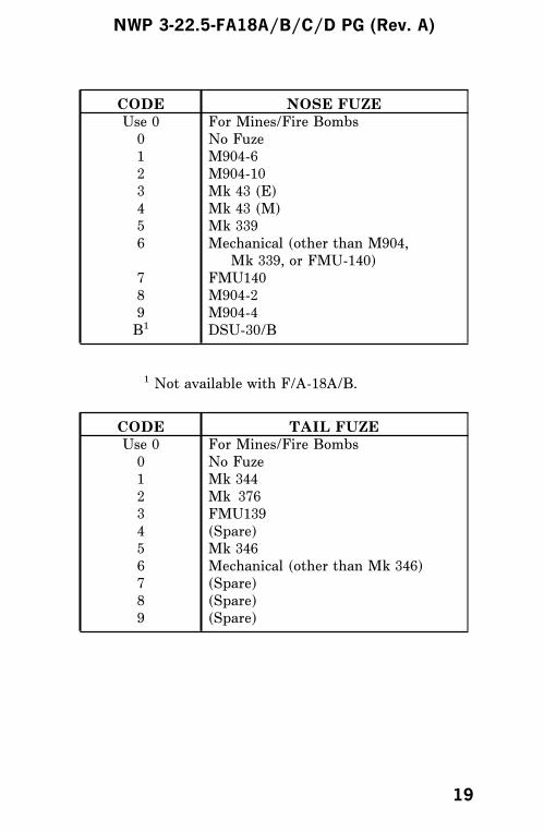
CODE NOSE FUZE
Use 0 For Mines/Fire Bombs
0 No Fuze
1 M904-6
2 M904-10
3 Mk 43 (E)
4 Mk 43 (M)
5 Mk 339
6 Mechanical (other than M904,
Mk 339, or FMU-140)
7 FMU140
8 M904-2
9 M904-4
B1 DSU-30/B
1 Not available with F/A-18A/B.
CODE TAIL FUZE
Use 0 For Mines/Fire Bombs
0 No Fuze
1 Mk 344
2 Mk 376
3 FMU139
4 (Spare)
5 Mk 346
6 Mechanical (other than Mk 346)
7 (Spare)
8 (Spare)
9 (Spare)
NWP 3-22.5-FA18A/B/C/D PG (Rev. A)
19
AIR-TO-AIR WEAPONS
M61A1 EXTERIOR INSPECTION
Preflight Checks
1. Gun electrical safety switch extended2. Manual clearing handle in cleared position3. Rounds limiter set (if applicable)4. Gun electrical cannon plug connected5. Ensure access door 6 closed, manual clearing
handle indicator extended.
NWP 3-22.5-FA18A/B/C/D PG (Rev. A)
20

NWP 3-22.5-FA18A/B/C/D PG (Rev. A)
21
AIM-7M/H/P EXTERIOR INSPECTION
PREFLIGHT CHECKS
1. BRU-32 with LAU-115 installed:a. Ground safety handle lockedb. Swaybraces seatedc. Cartridges installed; retainers/auxiliary cap
tightd. Launcher electrically connected
2. (Launchers) Safety release/lock drive in GREEN3. (LAU-116) Aft missile stop indicator flush with
launcher skin, trigger locked, and aft stop pin infull down position
4. Shear wafer mated to missile5. Motor SAFE/ARM mechanism - SAFE6. Wings and fins secure7. Fuze antenna strips and waveguide secure and
not damaged8. (LAU-115) SMP code set
NWP 3-22.5-FA18A/B/C/D PG (Rev. A)
22

NWP 3-22.5-FA18A/B/C/D PG (Rev. A)
23
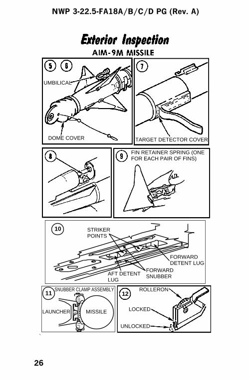
AIM-9M EXTERIOR INSPECTION
Preflight Checks
1. BRU-32/A with LAU-115/LAU-7 combinationinstalled:a. Ground safety handle lockedb. Swaybraces seatedc. Cartridges installed; retainers/auxiliary cap
tightd. Launcher electrically connected
2. Launcher detent wrench safety pin installed3. Detent holddown pin installed4. Motor safe/arm mechanism/selector - SAFE (if
applicable)5. Dome protector installed6. Umbilical connected to launcher7. Target detector cover installed
NOTE
When training missile is loaded, launcherumbilical block hooks will not engage missileumbilical block pins.
8. Hooks connected to umbilical block (ifapplicable)
9. Fin retainers engaged10. Visually inspect detent lugs engaged around
forward hanger and that the missile is restrainedin both directions
11. From fore and aft positions, rock firmly upwardsto ensure both sets of snubbers are firmlyengaged
12. Rolleron covers removed13. Aft fairing secure14. SMP code set
NWP 3-22.5-FA18A/B/C/D PG (Rev. A)
24

NWP 3-22.5-FA18A/B/C/D PG (Rev. A)
25
MISSILELAUNCHER
SNUBBER CLAMP ASSEMBLY ROLLERON
LOCKED
UNLOCKED
STRIKERPOINTS
AFT DETENTLUG
FORWARD SNUBBER
FORWARD DETENT LUG
UMBILICAL
DOME COVER TARGET DETECTOR COVER
FIN RETAINER SPRING (ONEFOR EACH PAIR OF FINS)
10
11 12
NWP 3-22.5-FA18A/B/C/D PG (Rev. A)
26
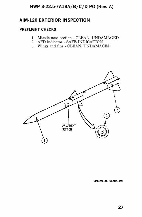
AIM-120 EXTERIOR INSPECTION
PREFLIGHT CHECKS
1. Missile nose section - CLEAN, UNDAMAGED2. AFD indicator - SAFE INDICATION3. Wings and fins - CLEAN, UNDAMAGED
NWP 3-22.5-FA18A/B/C/D PG (Rev. A)
27
AIR-TO-GROUNDWEAPONS
WEAPON CODES
Refer to Stores Information for weapon codes.
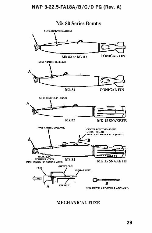
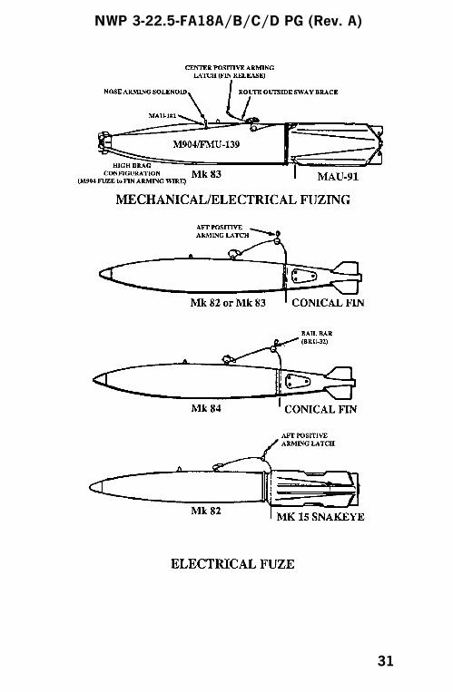
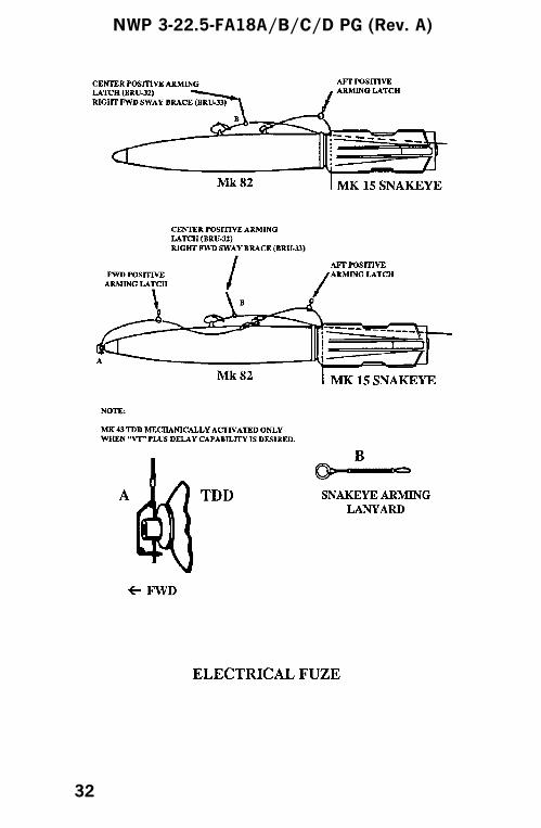
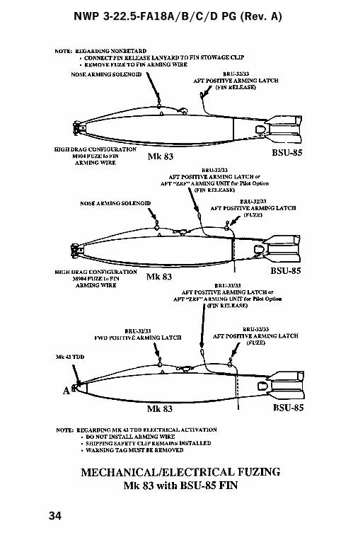
BOMBS NONRETARD/RETARD
Preflight Checks
1. Ground safety handle(s) locked2. Swaybraces seated3. Cartridges installed; retainers/auxiliary cap tight4. (VER) Adapter harness electrically connected5. Arming wire(s) installed6. Fuze set; safety pin/wire removed (if applicable)7. (BSU-85/86) Fin release lanyard stowed/
connected8. (Retard) Fin release band latch assembly safety
pin removed9. (Electric fuzing) Mk 122 safety switch lanyard
attached to center positive arming latch10. (FMU-139 Fuze) Preset functioning delay data
marked on fin11. SMP code set
NOTE
D The FMU-139 electric tail fuze does notrequire arming wire.
D (BSU-85/86) Pilot option low/high dragwith ZRF arming units only.
NWP 3-22.5-FA18A/B/C/D PG (Rev. A)
28
NWP 3-22.5-FA18A/B/C/D PG (Rev. A)
29

NWP 3-22.5-FA18A/B/C/D PG (Rev. A)
30
NWP 3-22.5-FA18A/B/C/D PG (Rev. A)
31
NWP 3-22.5-FA18A/B/C/D PG (Rev. A)
32

NWP 3-22.5-FA18A/B/C/D PG (Rev. A)
33
NWP 3-22.5-FA18A/B/C/D PG (Rev. A)
34

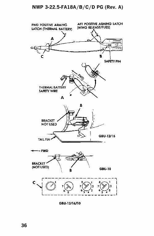
GBU-12, -16, -10
Preflight Checks
1. Ground safety handle locked2. Swaybraces seated3. Cartridges installed; retainers/auxiliary cap tight4. Thermal battery firing pin assembly safety wire
removed; arming cable properly installed.5. Guidance fins secure and free to move6. PRF code select switches set7. Safety pins installed in latch release lever and
wings; release lanyard properly installed.8. Mk 122 safety switch lanyard attached to center
positive arming latch.9. (FMU-139 fuze) Present functioning delay data
marked on fin.10. SMP code set
NWP 3-22.5-FA18A/B/C/D PG (Rev. A)
35
NWP 3-22.5-FA18A/B/C/D PG (Rev. A)
36
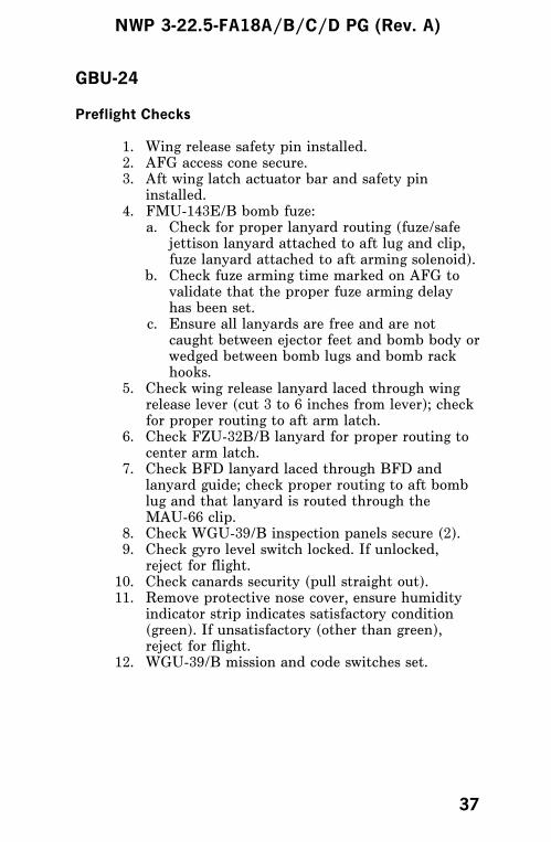
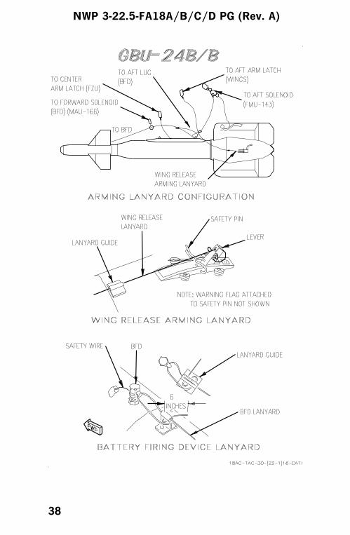
GBU-24
Preflight Checks
1. Wing release safety pin installed.2. AFG access cone secure.3. Aft wing latch actuator bar and safety pin
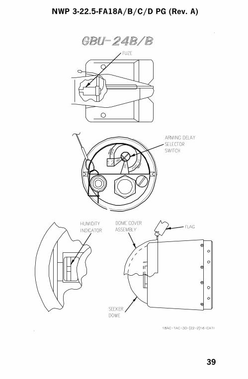
installed.4. FMU-143E/B bomb fuze:
a. Check for proper lanyard routing (fuze/safejettison lanyard attached to aft lug and clip,fuze lanyard attached to aft arming solenoid).
b. Check fuze arming time marked on AFG tovalidate that the proper fuze arming delayhas been set.
c. Ensure all lanyards are free and are notcaught between ejector feet and bomb body orwedged between bomb lugs and bomb rackhooks.
5. Check wing release lanyard laced through wingrelease lever (cut 3 to 6 inches from lever); checkfor proper routing to aft arm latch.
6. Check FZU-32B/B lanyard for proper routing tocenter arm latch.
7. Check BFD lanyard laced through BFD andlanyard guide; check proper routing to aft bomblug and that lanyard is routed through theMAU-66 clip.
8. Check WGU-39/B inspection panels secure (2).9. Check gyro level switch locked. If unlocked,
reject for flight.10. Check canards security (pull straight out).11. Remove protective nose cover, ensure humidity
indicator strip indicates satisfactory condition(green). If unsatisfactory (other than green),reject for flight.
12. WGU-39/B mission and code switches set.
NWP 3-22.5-FA18A/B/C/D PG (Rev. A)
37
NWP 3-22.5-FA18A/B/C/D PG (Rev. A)
38
NWP 3-22.5-FA18A/B/C/D PG (Rev. A)
39

NWP 3-22.5-FA18A/B/C/D PG (Rev. A)
40
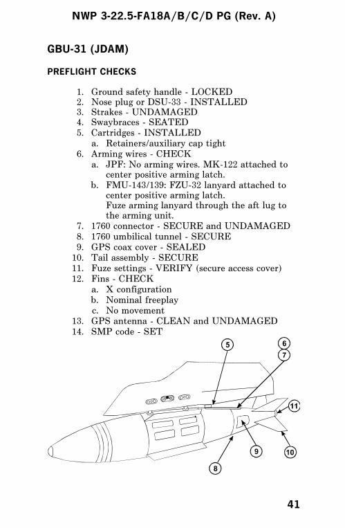
GBU-31 (JDAM)
PREFLIGHT CHECKS
1. Ground safety handle - LOCKED2. Nose plug or DSU-33 - INSTALLED3. Strakes - UNDAMAGED4. Swaybraces - SEATED5. Cartridges - INSTALLED
a. Retainers/auxiliary cap tight6. Arming wires - CHECK
a. JPF: No arming wires. MK-122 attached tocenter positive arming latch.
b. FMU-143/139: FZU-32 lanyard attached tocenter positive arming latch.Fuze arming lanyard through the aft lug tothe arming unit.
7. 1760 connector - SECURE and UNDAMAGED8. 1760 umbilical tunnel - SECURE9. GPS coax cover - SEALED10. Tail assembly - SECURE11. Fuze settings - VERIFY (secure access cover)12. Fins - CHECK
a. X configurationb. Nominal freeplayc. No movement
13. GPS antenna - CLEAN and UNDAMAGED14. SMP code - SET
NWP 3-22.5-FA18A/B/C/D PG (Rev. A)
41
GBU-31 EMPLOYMENT
POSTSTART CHECKS
1. MU ID - VERIFY
2. Mission data download - VERIFY
3. HOLD ALL or HOLD MU - SELECT
4. JDAM BIT - PERFORM
5. S/W - SELECT
a. OFB166 (J-84) or OFC166 (J-109) - VERIFY
6. GPS time - VERIFY GOOD
7. Two-digit HERR/VERR - VERIFY
8. INS control knob - IFA
9. A/G master mode - SELECT
10. Fuzing - SET
11. J-84 or J-109 - SELECT
12. PP or TOO - SELECT
13. REL TYPE - SELECT
a. MAN or AUTO LOFT - SELECT
14. QTY - SELECT
a. Box desired stations for quantity release
b. RTN - SELECT (use STEP to move betweenweapons)
15. NO GPS KEYS and NO GPS DATA cuesremoved - VERIFY
16. MSN - SELECT
a. Mission data - VERIFY
b. JPF settings - VERIFY
NWP 3-22.5-FA18A/B/C/D PG (Rev. A)
42
c. Desired mission - SELECTED
NOTE
• As long as JDAM is not deselected, backgroundpower is applied to all JDAM weapons. This aidsin fault detection and avoids the 2:30 wait by theGPS warmup timer. JDAM does not have to bedeselected for catapult launch.
• Once QUANTITY RELEASE is selected, theSTEP option will only step between weapons inthe selected quantity.
• When editing a mission, once a terminal headingis defined, there is no means of clearing theheading to re-enter heading undefined mode.
ENROUTE CHECKS
1. A/G master mode - SELECT2. Priority station(s) READY - VERIFY3. EFUZE ON (JPF) or MFUZE TAIL
(FMU-139/143) - VERIFY4. ALIGN QUAL 01 GOOD all stations - CHECK5. Maneuver for transfer alignment - AS
REQUIRED6. MSN - SELECT (to verify mission, if desired)
NOTE
Troubleshooting involving deselecting/rese-lecting JDAM within 3 minutes of intendedweapon release can lead to mission failure dueto GPS warmup countdown timer operation(2 min 30 sec delay).
JDAM PREPLANNED DELIVERY
1. A/G master mode - SELECT2. ALN QUAL 01 GOOD - VERIFY3. Priority station(s) READY - VERIFY4. Master arm - ARM
NWP 3-22.5-FA18A/B/C/D PG (Rev. A)
43

5. J-84 or J-109 not Xed on HUD - VERIFY6. Weapon release button - PRESS
JDAM TOO DELIVERY
POSTLAUNCH CHECKS
1. Master arm switch - SAFE2. Safe escape from flight clearance - COMPLY
If JDAM remains on aircraft -3. A/G or NAV master mode - SELECT4. J-84 or J-109 - SELECT5. ERASE - SELECT6. ACPT - SELECT
POSTFLIGHT CHECKS
1. No ‘‘C’’ MSP codes remain - VERIFY
NWP 3-22.5-FA18A/B/C/D PG (Rev. A)
44

GBU-31 SIMULATED ATTACK
PREFLIGHT CHECKS
1. For each empty station:a. Fuze code (optional): 08 JPFb. Store code: C0 JDAM
2. On BRU-32 ensure hooks - CLOSEDAOC is not enabled in JDAM training mode.
POST-START CHECKS
1. SMS inventories JDAM station - SELECTED2. JDAM indicates ULK-TEST-STBY-XFER3. A/G master mode - SELECTED4. SIM - SELECTED5. JDAM - SELECTED
If no bulk data on MU -1. Mission data - ENTER2. JDAM checklist - FOLLOW
NOTE
• JDAM ERASE option is not enabled in trainingmode.
• Transfer alignment does not occur in trainingmode. JDAM will always indicate ALN QUAL 01GOOD.
• Weapon step and data freeze operate normal intraining mode.
• If only one training JDAM station selected,deselecting/reselecting JDAM may be requiredafter pickle.
NWP 3-22.5-FA18A/B/C/D PG (Rev. A)
45

AGM-154A (JSOW)
PREFLIGHT CHECKS
1. Ground safety handle - LOCKED2. Swaybraces - SEATED3. Cartridges - INSTALLED
a. Retainers/auxiliary cap - TIGHT4. Umbilical and umbilical bail - CONNECTED5. Suspension lug retaining pins (2) - REMOVED6. Weapon integrity - CHECK
a. No chips, cracks, or dents on any surface7. Wings - CHECK
a. No chips, cracks, or defects8. GPS antenna - NO DAMAGE9. (Telemetry rounds) TIK antennas - NOT
DAMAGED OR LOOSE10. Fins - ALIGNED and LOCKED
a. Parallel to missile and not damaged,defective, or loose
11. Horizontal stabilizers - CHECKa. Not damaged, loose, or misaligned
12. SMP code - SET (F0)13. MU - INSTALL
4
8
5
7 10
11
NWP 3-22.5-FA18A/B/C/D PG (Rev. A)
46

AGM-154A EMPLOYMENT
POSTSTART CHECKS
1. MUMI - CHECKa. Good download (CDATA advisory)
2. Accurate ZULU date and time entered -CONFIRM
3. BIT/stores/station - CHECKa. If WFAIL or WDEGD, perform IBIT
4. A/G master mode - SELECT5. Weapon - SELECT
a. JSA or TJSA boxed6. JSOW display - SELECT
a. Select desired mode (PP, SL, T001, T002)b. Select/edit desired MISSION for each weaponc. Approximately 2 minutes after countdown
time removed from JSOW/stores displays,confirm at least 1 SV ACQD. Check status ofall loaded JSOW(1) If no SVs ACQD, perform GPS
troubleshooting proceduresd. HRM OVRD - As desired (if applicable)
7. A/G master mode - DESELECT
EN ROUTE CHECKS
1. A/G master mode - SELECT2. Weapon - SELECT
a. JSA or TJSA boxed3. BIT/stores/station - CHECK
a. If WFAIL or WDEGD, perform IBIT4. JSOW display - SELECT
a. Check JSOW display of all loaded weaponsb. Confirm desired mission selected for each
weaponc. ALN QUAL - 01 GOOD
(1) If ALN QUAL not 01 GOOD, performaircraft maneuvers to improve QUAL
d. SV ACQD - 4 or more (if less than 4, JSOWperformance may be degraded)
NWP 3-22.5-FA18A/B/C/D PG (Rev. A)
47
NOTE
Deselecting JSOW on the stores display re-moves power from all loaded weapons, requir-ing a repeat of the EN ROUTE Procedures.
LAUNCH CHECKS
1. A/G master mode - SELECT2. TOO mission - DESIGNATE TARGET3. Master arm switch - ARM4. JSOW - CHECK RDY
In Range/In Zone -
5. Weapon release button - PRESS
NOTE
It takes up to 2 seconds from weapon releasebutton actuation to weapon separation fromthe aircraft.
AFTER LANDING CHECKS
1. Ensure aircraft and missile data is erased.a. If HOLD ALL is not boxed on MUMI page,
the aircraft automatically erases.b. If HOLD ALL is boxed, data must be
manually erased.
c. To erase missile data, box JSOW ERASE onstores display. ERASE appears beneath eachstation carrying JSOW.
TROUBLESHOOTING PROCEDURES
1. If no GPS data or no GPS crypto keys aredisplayed on JSOW display or any other OCSanomalies are observed, rebox OCS on MUMIpage. If OCS download unsuccessful, performIBIT on weapon and then reattempt OCSdownload.
NWP 3-22.5-FA18A/B/C/D PG (Rev. A)
48

2. If JSOW indicates WDEGD or WFAIL, performIBIT of weapon.
3. ALN QUAL must be better than 10 to acquireSVs. If ALN QUAL still does not decrease,deselect/reselect JSOW on stores page (deselectremoves all power from weapon and reselectreinitializes weapon).
4. If JSOW is unable to acquire SVs and/orindicates a JAMMED status, perform thefollowing:a. Ensure JSOW GPS antenna is not obstructed.
If aircraft GPS is receiving SVs, JSOWshould be receiving SVs.
b. Ensure aircraft INS is aligning properly withposition accuracy within 5 nm horizontal and10K feet vertical. Aircraft INS should be onand aligned prior to selecting JSOW.
c. Ensure ZULU time is entered within 10minutes of actual time and correct date isentered. If date and time are reentered,JSOW IBIT must be performed for weapon toaccept new data. It may take up to 3 minutesfor JSOW to acquire SVs following IBIT.
d. If still no SVs acquired, deselect/reselectJSOW on stores page.
e. If still no SVs acquired, GPS crypto keys oralmanac data may be corrupted, requiring anew MU download from TAMPS.
NWP 3-22.5-FA18A/B/C/D PG (Rev. A)
49

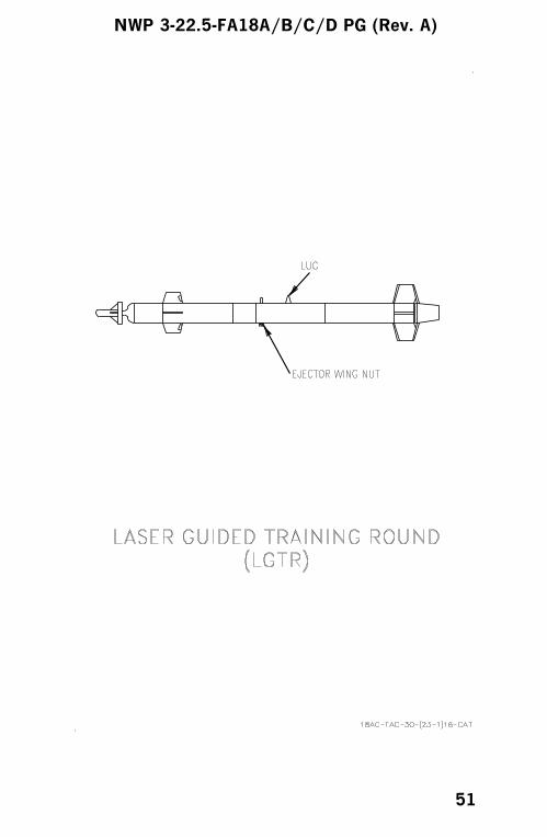
LGTR
Preflight Checks
1. Ensure LGTR unique practice bomb adapterbrackets are attached to forward and aftswaybraces and the practice bomb restricter isattached to the gun piston assembly.
2. Check that the LGTR is securely attached to theMER/IMER or TER/ITER; canards must be freemoving and undamaged.
3. Ensure the seeker dome cover is removed and theseeker dome is clean and undamaged.
4. Check that the laser code select switch iscorrectly set.
5. Ensure the ejector wing nut is removed and theejector seats against the restricter.
6. Ensure that the signal marker is installed and theaft boattail is secure.
If the LGTR is released with the wing nutinstalled (i.e., a non-ejected release) weaponto aircraft impact is likely.
NWP 3-22.5-FA18A/B/C/D PG (Rev. A)
50
NWP 3-22.5-FA18A/B/C/D PG (Rev. A)
51
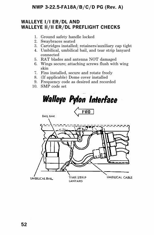
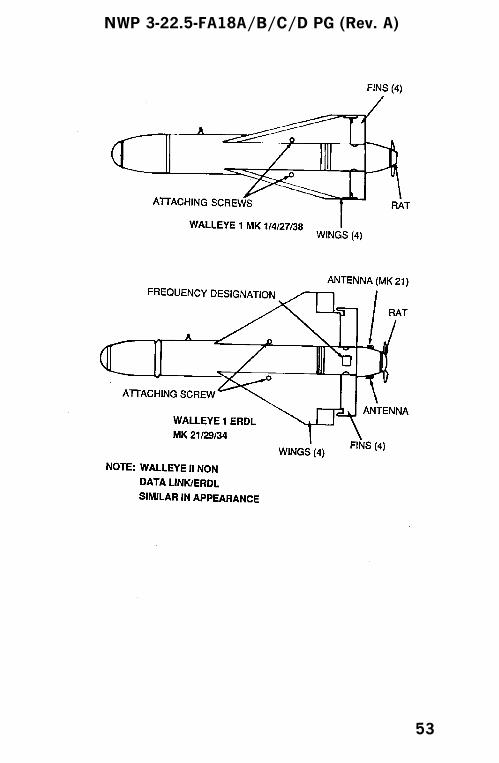
WALLEYE I/I ER/DL ANDWALLEYE II/II ER/DL PREFLIGHT CHECKS
1. Ground safety handle locked2. Swaybraces seated3. Cartridges installed; retainers/auxiliary cap tight4. Umbilical, umbilical bail, and tear strip lanyard
connected5. RAT blades and antenna NOT damaged6. Wings secure; attaching screws flush with wing
skin7. Fins installed, secure and rotate freely8. (If applicable) Dome cover installed9. Frequency code as desired and recorded10. SMP code set
NWP 3-22.5-FA18A/B/C/D PG (Rev. A)
52
NWP 3-22.5-FA18A/B/C/D PG (Rev. A)
53
WALLEYE I/II EMPLOYMENT
POSTSTART CHECKS
1. Master arm switch - SAFE2. A/G master mode - SELECT3. Weapon - SELECT
a. WE boxed on stores display4. Fuzing - BRIEFED OPTION and BIT PAGE
GO5. Weapon video - ADJUST6. DSM-77B test - COMPLETED7. Weapon - DESELECT
a. WE unboxed
EN ROUTE CHECK
1. Boresight check - COMPLETEDAzimuth error mils L/R
TARGET AREA CHECKS
1. A/G master mode - SELECT2. Weapon - SELECT
a. WE boxed3. Fuzing - BRIEFED
OPTION and BIT PAGE GO4. HUD reticle - ON TARGET5. Weapon video target gate - ON TARGET6. Cage/uncage button - UNCAGE7. Master arm switch - ARM8. Weapon release button - PRESS (followed by an
evasive maneuver)
NWP 3-22.5-FA18A/B/C/D PG (Rev. A)
54
WALLEYE I/II ER/DL EMPLOYMENT(SINGLE AIRCRAFT OPERATION)
POSTSTART CHECKS
1. Master arm switch - SAFE2. A/G master mode - SELECT3. Weapon - SELECT
a. WEDL boxed4. Fuzing - BRIEFED OPTION and BIT PAGE
GO5. DSM-77B test - COMPLETED6. Data link pod and pod video - SELECT
a. DL9, DL13 or DLP as applicable andPODVID boxed
7. Weapon frequency - SELECT CHANNEL(Prebriefed or Manual)
8. RF option - ONa. VTR displayed
9. Cage/uncage button - UNCAGEa. Target gate moves when uncaged
10. TDC - PRESS and HOLD WHILE SLEWINGIN ALL DIRECTIONSa. MAP displayed at 1/2 size
11. Cage/uncage button - CAGE12. RF option - OFF
a. VTR disappears
NOTE
To prevent VTR tape jamming, wait 30 sec-onds before deselecting A/G master mode.
13. A/G master mode - DESELECT
TARGET AREA CHECKS
1. A/G master mode - SELECT2. Weapon - SELECT
a. WEDL boxed3. Fuzing - BRIEFED OPTION and BIT PAGE
GO4. Data link pod and pod video - SELECT
NWP 3-22.5-FA18A/B/C/D PG (Rev. A)
55
a. DL9, DL13, DLP, or WEPD as applicable andPODVID boxed
5. Weapon frequency - SELECT CHANNEL(prebriefed or manual)
6. HUD reticle - ON TARGET7. Weapon video target gate - ON TARGET8. Cage/uncage button - UNCAGE
a. Weapon locks on targetb. If weapon does not lock on target
(1) TDC - PRESS and HOLD, slewing targetgate back to target
(2) TDC - RELEASE(repeat steps (1) and (2) until lockon)
9. Master arm switch - ARM10. Weapon release button - PRESS (followed by an
evasive maneuver)11. Aft antenna - SELECT (if required)
a. A ANT boxed12. Target lockon - MONITOR/UPDATE
WALLEYE I/II ER/DL EMPLOYMENT(DUAL AIRCRAFT OPERATION)
POSTSTART CHECKS
1. Master arm switch - SAFE2. A/G master mode - SELECT3. (weapon aircraft) Weapon - SELECT
a. WE DL boxed4. (pod aircraft) Data link pod - SELECT
a. DL9, DL13, DLP, or WEPD as applicable5. (pod aircraft) Frequency - SELECT CHANNEL
(prebriefed or manual)6. (pod aircraft) RF option - ON
a. VTR displayed7. Video display - ADJUSTED8. (weapon aircraft) DSM-77B and DSM-139
tests - COMPLETED9. (weapon aircraft) Weapon station - DESELECT
and RESELECTa. PSI disappears
10. Data link marriage - CHECK
NWP 3-22.5-FA18A/B/C/D PG (Rev. A)
56
Weapon aircraft performs data link check inconjunction with pod aircraft as follows:a. (pod aircraft) RF option - ONb. (weapon aircraft) cage/uncage button -
UNCAGEc. (pod aircraft) TDC - PRESS
Check that crosshairs can be locked on newtarget and that MAP reduces in size
d. (pod aircraft) PSI commands - CHECKe. (weapon aircraft) Weapon station -
DESELECTED and RESELECT(1) PSI removed
11. (Pod aircraft) RF option - OFFa. VTR disappears
NOTE
To prevent VTR tape jamming, wait 30 sec-onds before deselecting A/G master mode.
12. (weapon aircraft) Fuzing - PREBRIEFEDOPTION and BIT PAGE GO
13. A/G master mode - DESELECT
EN ROUTE CHECK
1. (weapon aircraft) Boresight check -COMPLETED
TARGET AREA CHECKS
1. A/G master mode - SELECT2. (weapon aircraft) Weapon - SELECT
a. WE DL boxed3. (pod aircraft) Data link pod - SELECT
a. DL9, DL13, DLP, or WEPD as applicableboxed
b. Ensure correct channel selected4. (weapon aircraft) Fuzing - BRIEFED OPTION
and BIT PAGE GO5. (pod aircraft) Forward or aft antenna - AS
REQUIRED6. (pod aircraft) RF option - ON
a. VTR appears
NWP 3-22.5-FA18A/B/C/D PG (Rev. A)
57
7. (pod aircraft) Sensor control switch (PSI) - ASREQUIRED (prebriefed)
8. (weapon aircraft) HUD reticle - ON TARGET9. (weapon aircraft) Video target gate - ON
TARGET10. (weapon aircraft) Cage/uncage button -
UNCAGEa. Weapon locks on target, go to step 11b. Weapon does not lock on target
(1) Cage weapon seeker and repeat steps 8thru 10
11. (pod aircraft) PSI - AS REQUIRED (prebriefed)12. (weapon aircraft) Master arm switch - ARM13. (weapon aircraft) Weapon release button -
PRESS (followed by an evasive maneuver)14. (pod aircraft) Weapon lockon - MONITOR/
UPDATE
NWP 3-22.5-FA18A/B/C/D PG (Rev. A)
58
WALLEYE I SIMULATED ATTACK
1. A/G master mode - SELECT2. Weapon - SELECT3. Master arm switch - SAFE4. SIM option - SELECT5. Fuzing - BRIEFED OPTION and BIT PAGE
GO6. HUD reticle - ON TARGET7. Weapon video target gate - ON TARGET8. Cage/uncage button - UNCAGE9. Master arm switch - simulate ARM (do not ARM
unless required/desired for chaff/flare utilization)
When weapon release conditions are satisfied -
10. Weapon release button - PRESS (followed by anevasive maneuver)
AFTER SIMULATED ATTACK
NOTE
If master arm switch - ARM is required(chaff/flare) or is inadvertently selected, en-sure master arm switch - SAFE is selectedfollowing simulated attack and prior to dese-lecting SIM.
1. SIM option - DESELECT
WALLEYE I ER/DL SIMULATED ATTACK(SINGLE AIRCRAFT OPERATION)
1. A/G master mode - SELECT2. Weapon - SELECT
a. WE DL3. Master arm - SAFE4. SIM option - SELECT5. Fuzing - BRIEFED OPTION and BIT PAGE
GO
NWP 3-22.5-FA18A/B/C/D PG (Rev. A)
59
6. Data link pod and pod video - SELECTa. PODVID DLP, DL9, DL13, or WEPD as
applicable7. Weapon frequency - SELECT CHANNEL
(Prebriefed or Manual)8. HUD reticle - ON TARGET9. Weapon video target gate - ON TARGET10. Cage/uncage button - UNCAGE
a. Weapon locks on targetb. If weapon does not lock on target
(1) TDC - PRESS and HOLD, slewing targetgate back to target
(2) TDC - RELEASERepeat steps (1) and (2) until lockon
11. Master arm switch - simulate ARM (do not ARMunless required/desired for chaff/flare utilization)
When weapon release conditions are satisfied -
12. Weapon release button - PRESS (followed by anevasive maneuver)
13. Aft antenna - SELECT (if required)14. Target lockon - MONITOR/UPDATE
AFTER SIMULATED ATTACK
NOTE
If master arm switch - ARM is required(chaff/flare) or is inadvertently selected, en-sure master arm switch - SAFE is selectedfollowing simulated attack and prior to dese-lecting SIM.
1. SIM option - DESELECT
NWP 3-22.5-FA18A/B/C/D PG (Rev. A)
60

WALLEYE I ER/DL SIMULATED ATTACK(DUAL AIRCRAFT OPERATION)
1. A/G master mode - SELECT2. (weapon aircraft) Weapon - SELECT
a. WEDL boxed3. (weapon aircraft) Master arm switch - SAFE4. (weapon aircraft) SIM option - SELECT5. (pod aircraft) Data link pod - SELECT
a. DLP, DL9, DL13, or WEPD as applicableb. Ensure correct channel selected
6. (weapon aircraft) Fuzing - BRIEFED OPTIONand BIT PAGE GO
7. (pod aircraft) Forward or aft antenna - ASREQUIRED
8. (pod aircraft) RF option - ONa. VTR appears
When ready for weapon lockon -
9. (pod aircraft) Sensor control switch (PSI) - ASREQUIRED (prebriefed)
10. (weapon aircraft) HUD reticle - ON TARGET11. (weapon aircraft) Weapon video target gate - ON
TARGET12. (weapon aircraft) Cage/uncage button -
UNCAGEa. Weapon locks on target, go to step 13b. Weapon does not lock on target
(1) Cage weapon seeker and repeat steps 10thru 12
13. (pod aircraft) PSI - AS REQUIRED (prebriefed)14. (weapon aircraft) Master arm switch - simulate
ARM (do not ARM unless required/desired forchaff/flare utilization)
When ready for weapon release -
15. (weapon aircraft) Weapon release button -PRESS (followed by an evasive maneuver)
16. (pod aircraft) Weapon lockon - MONITOR/UPDATE
NWP 3-22.5-FA18A/B/C/D PG (Rev. A)
61
AFTER SIMULATED ATTACK
NOTE
If master arm switch - ARM is required(chaff/flare) or is inadvertently selected, en-sure master arm switch - SAFE is selectedfollowing simulated attack and prior to dese-lecting SIM.
1. SIM option - DESELECT
NWP 3-22.5-FA18A/B/C/D PG (Rev. A)
62
AN/AWW-9B/-13 DATA LINK POD(Control-Monitor Set)
PREFLIGHT CHECKS
1. Ground safety handle in locked position2. Sway braces seated3. Cartridges installed/auxiliary cartridge cap tight4. Umbilical cable and bail connected5. Antenna radomes NOT damaged6. Video tape installed, if desired (fwd access door)7. (AN/AWW-9) Frequency code switch set as
desired (aft access door)8. (AN/AWW-13) BIT/Channel select set to 0099. Pod power switch (CB1) - ON (aft access door)10. Aircraft mode switch set - 2A/C11. Pod access doors secured12. SMP code set
NWP 3-22.5-FA18A/B/C/D PG (Rev. A)
63

RFI FILTER & CIRCUIT BREAKER
AN/AWW-9B/-13
NWP 3-22.5-FA18A/B/C/D PG (Rev. A)
64
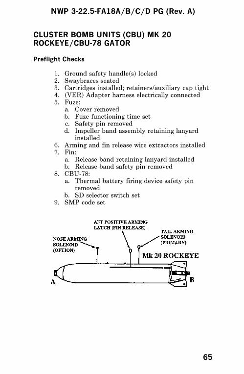
CLUSTER BOMB UNITS (CBU) MK 20ROCKEYE/CBU-78 GATOR
Preflight Checks
1. Ground safety handle(s) locked2. Swaybraces seated3. Cartridges installed; retainers/auxiliary cap tight4. (VER) Adapter harness electrically connected5. Fuze:
a. Cover removedb. Fuze functioning time setc. Safety pin removedd. Impeller band assembly retaining lanyard
installed6. Arming and fin release wire extractors installed7. Fin:
a. Release band retaining lanyard installedb. Release band safety pin removed
8. CBU-78:a. Thermal battery firing device safety pin
removedb. SD selector switch set
9. SMP code set
NWP 3-22.5-FA18A/B/C/D PG (Rev. A)
65
FMU-140/B FUZE INSPECTION
NWP 3-22.5-FA18A/B/C/D PG (Rev. A)
66
NWP 3-22.5-FA18A/B/C/D PG (Rev. A)
67

MK 77 FIRE BOMB
Preflight Checks
1. Ground safety handles in LOCKED position onloaded stations
2. Swaybraces properly seated3. Cartridges installed in all loaded bomb racks;
cartridge retainers and auxiliary cartridge captight (all stations)
4. Fire bomb not leaking or damaged5. Arming lanyards properly routed and connected6. Inspect Mk 13 initiator as follows:
a. Retaining rings tightb. Tear out section of the initiator not damagedc. Initiator firing mode selectors set
7. SMP codes set
NWP 3-22.5-FA18A/B/C/D PG (Rev. A)
68
NWP 3-22.5-FA18A/B/C/D PG (Rev. A)
69
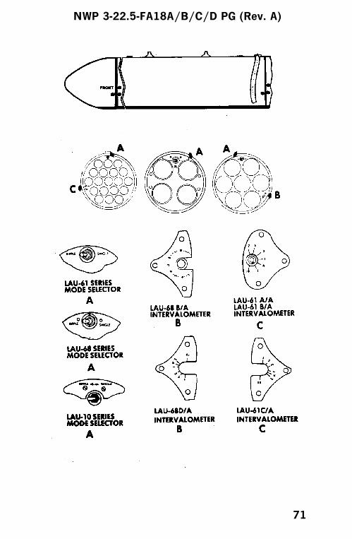
ROCKETS
Preflight Checks
1. Ground safety handles locked2. Swaybraces seated3. Cartridges installed; retainers/auxiliary cap tight4. VER adapter harness electrically connected5. Launcher:
a. Safety pin installedb. Not electrically connectedc. Mode selector switch setd. (LAU-61/68) Intervalometer set to Ae. (LAU-10) Detent lift arms - FIRE
6. (Mk 84 Chaff) Fuze set as desired7. (If applicable) Fairings installed8. SMP code set
NWP 3-22.5-FA18A/B/C/D PG (Rev. A)
70
NWP 3-22.5-FA18A/B/C/D PG (Rev. A)
71
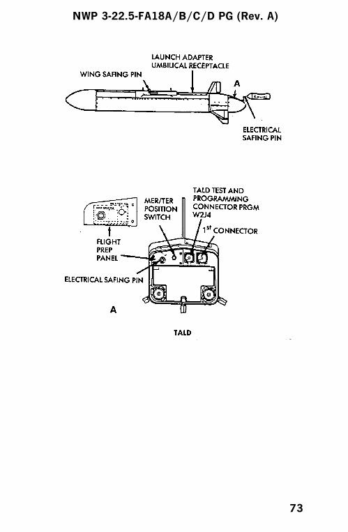
TALD
Preflight Checks
1. Ground safety handle/safety stop lever locked2. Swaybraces seated/adjusted3. Cartridges installed; retainers/auxiliary cap/
breech caps tight4. BRU-42:
a. Adapter harness electrically connectedb. All unloaded suspension hooks open
5. TALD:a. Electrical safing pin installedb. MER/TER position switch set for station
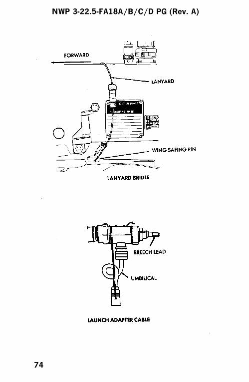
loaded6. Wing safing pin installed; lanyard bridle attached
to safing pin and rack7. Launch adapter umbilical not connected to store8. Cartridge and launch adapter installed in/on
breech9. SMP code set
NWP 3-22.5-FA18A/B/C/D PG (Rev. A)
72
NWP 3-22.5-FA18A/B/C/D PG (Rev. A)
73
NWP 3-22.5-FA18A/B/C/D PG (Rev. A)
74

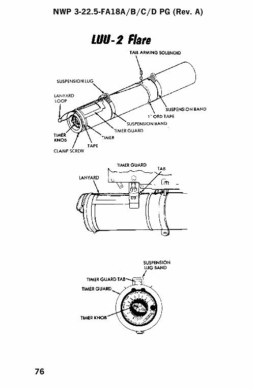
PYROTECHNICS LUU-2 FLARE/MK 58 MLM
Preflight Checks
1. Ground safety handle/safety stop lever(s) locked2. Swaybraces seated/adjusted3. Cartridges installed; retainers/auxiliary cap/
breech cap(s) tight4. MER/BRU-41:
a. Adapter harness electrically connectedb. All unloaded suspension hooks openc. Ejector feet positionedd. (MER) Mode selector sete. (MER) Electric safety pin installed
5. LUU-2:a. Timer setb. Lanyard loop connected to timer knobc. Timer guard tab positioned behind swaybrace
adapter bracketd. Lanyard connected to tail solenoid
6. (Mk 58 MLM) Arming wire attached to BASBand pull ring
7. SMP code set
NOTE
LUU-2s are only carried on the centerline andoutboard MER stations.
NWP 3-22.5-FA18A/B/C/D PG (Rev. A)
75
NWP 3-22.5-FA18A/B/C/D PG (Rev. A)
76

NWP 3-22.5-FA18A/B/C/D PG (Rev. A)
77
PRACTICE BOMBS MK 76/BDU-33D/B/MK 106/BDU-48/B
Preflight Checks
1. Ground safety handle/safety stop lever(s) locked2. Swaybraces seated/adjusted3. Cartridges installed; retainers/auxiliary cap/
breech cap(s) tight4. MER/BRU-41:
a. Adapter harness electrically connectedb. All unloaded suspension hooks openc. (MER) Mode selector setd. (MER) Electrical safety pin installed
5. (BDU-33) Safety block with safety pin installed6. (Mk 106) Firing device cotter pin and safety pin
removed7. SMP code set
NWP 3-22.5-FA18A/B/C/D PG (Rev. A)
78
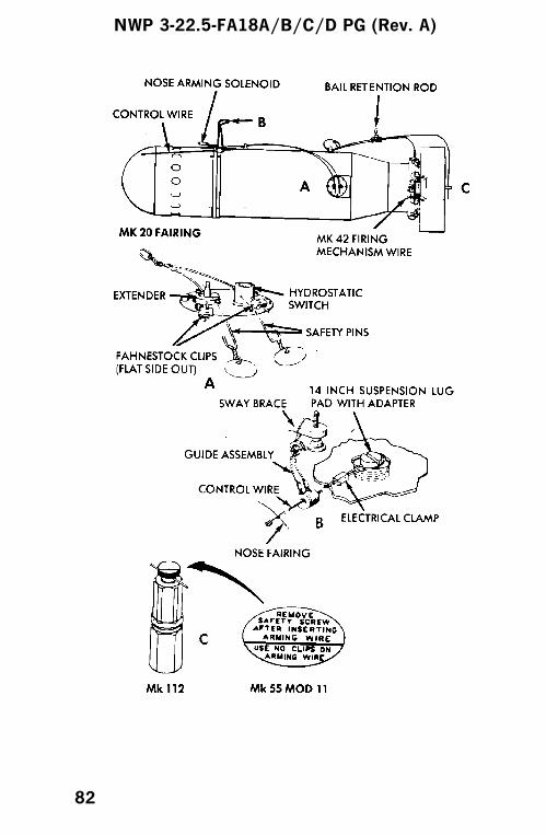
MINES MK 52/55/56/62/63/65
Preflight Checks
1. Ground safety handle locked2. Swaybraces seated3. Cartridges installed; retainers/auxiliary cap tight4. Mk 52/55/56:
a. Parachute pack arming wire installed; safetypin/screw removed
b. (Mk 56) Safety pins removed from releasepins
c. Arming wires installedd. Arming device safety pin(s) removed
5. Mk 62/63/65:a. Arming wires/lanyard installedb. (Mk 62/63) Arming device safety wire
removedc. (Mk 62/Mk 15 fin) Fin release band latch
assembly safety pin removedd. (Mk 62/BSU-86 fin) Fin release lanyard
connectede. (Mk 63) Fin release lanyard and pin
installed; safety pin removedf. (Mk 65)
(1) Safety bar removed(2) Altitude switch set - LO
Do not stand directly behind a mine. Theparapak is explosive (Mk 52/55/56/65).
6. SMP code set
NWP 3-22.5-FA18A/B/C/D PG (Rev. A)
79

NWP 3-22.5-FA18A/B/C/D PG (Rev. A)
80

NWP 3-22.5-FA18A/B/C/D PG (Rev. A)
81
NWP 3-22.5-FA18A/B/C/D PG (Rev. A)
82
NWP 3-22.5-FA18A/B/C/D PG (Rev. A)
83
NWP 3-22.5-FA18A/B/C/D PG (Rev. A)
84
NWP 3-22.5-FA18A/B/C/D PG (Rev. A)
85

MINES EMPLOYMENT/FLIGHTDIRECTOR MODE
POSTSTART CHECKS
1. Master arm switch - SAFE2. A/G master mode - SELECT3. Weapon - SELECT
a. Weapon boxed on stores display4. Program - SELECT5. FD - SELECT6. UFC - SELECT7. Fuzing, quantity, multiple, interval, bank
angle - ENTER8. Course select switch - SET BRIEFED RUN IN
HDG
TARGET AREA CHECKS
1. A/G master mode - SELECT2. Weapon - SELECT
a. Weapon boxed on stores display3. D/L - UNBOXED ON HI4. VEC - UNBOXED ON HI5. Program - CHECK6. Course select - CHECK7. TDC - AS DESIRED8. TGT - DESIGNATE9. Course line steering - ATTEMPT TO SET UP
ON RUN IN HDG10. A/P SELECT11. CPL - Colonize 15,000 feet prior to first impact12. Master arm switch - ARM13. Weapon release button - PRESS AND HOLD
UNTIL FINAL RELEASE14. A/P - DISENGAGE
NWP 3-22.5-FA18A/B/C/D PG (Rev. A)
86

DESTRUCTORS MK 36/40 DST
Preflight Checks
1. Ground safety handle locked2. Swaybraces seated3. Cartridges installed; retainers/auxiliary cap(s)
tight4. Arming wires installed5. Arming device safety wire removed6. (Mk 36/Mk 15 fin) Fin release band latch
assembly safety pin removed7. (Mk 36/BSU-86 fin) Fin release lanyard
connected8. (Mk 40/MAU-91) Fin release lanyard and pin
installed; safety pin removed9. SMP code set
NOTE
Line diagram illustrating arming cable rig-ging for the Mk 36 DST with Mk 16 tailsection and Mk 40 DST with Mk 12 tailsection to be provided.
NWP 3-22.5-FA18A/B/C/D PG (Rev. A)
87
NWP 3-22.5-FA18A/B/C/D PG (Rev. A)
88

AIR-TO-GROUND MISSILES
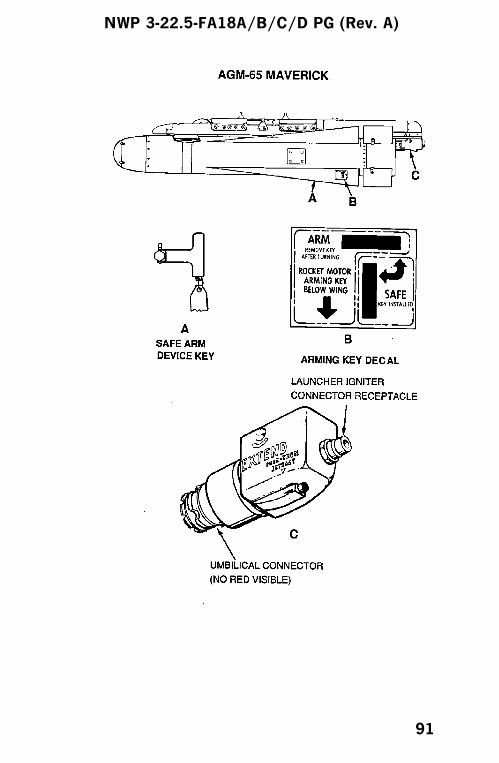
AGM-65E/F MAVERICK PREFLIGHT CHECKS
1. BRU-32 with LAU-117 installeda. Ground safety handle lockedb. Sway braces seatedc. Cartridges installed; retainers/auxiliary cap
tightd. Launcher electrically connected
2. Missile:a. Safe/Arm device key - SAFEb. Umbilical connector mated - NO RED
VISIBLEc. Ignitor cable NOT connected to launcher
igniter connector receptacle3. SMP code set
NWP 3-22.5-FA18A/B/C/D PG (Rev. A)
(89 blank)/90
NWP 3-22.5-FA18A/B/C/D PG (Rev. A)
91
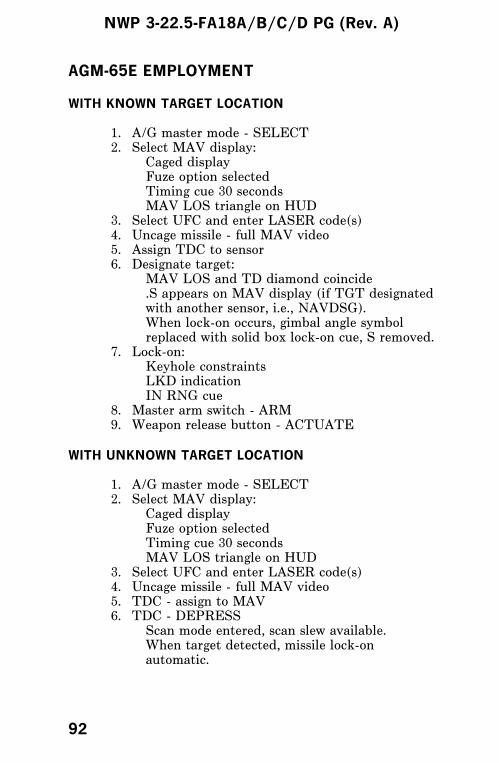
AGM-65E EMPLOYMENT
WITH KNOWN TARGET LOCATION
1. A/G master mode - SELECT2. Select MAV display:
Caged displayFuze option selectedTiming cue 30 secondsMAV LOS triangle on HUD
3. Select UFC and enter LASER code(s)4. Uncage missile - full MAV video5. Assign TDC to sensor6. Designate target:
MAV LOS and TD diamond coincide.S appears on MAV display (if TGT designatedwith another sensor, i.e., NAVDSG).When lock-on occurs, gimbal angle symbolreplaced with solid box lock-on cue, S removed.
7. Lock-on:Keyhole constraintsLKD indicationIN RNG cue
8. Master arm switch - ARM9. Weapon release button - ACTUATE
WITH UNKNOWN TARGET LOCATION
1. A/G master mode - SELECT2. Select MAV display:
Caged displayFuze option selectedTiming cue 30 secondsMAV LOS triangle on HUD
3. Select UFC and enter LASER code(s)4. Uncage missile - full MAV video5. TDC - assign to MAV6. TDC - DEPRESS
Scan mode entered, scan slew available.When target detected, missile lock-onautomatic.
NWP 3-22.5-FA18A/B/C/D PG (Rev. A)
92
7. Lock-on:Keyhole constraintsLKD indicationIN RNG cue
8. Master arm - ARM9. Weapon release button - ACTUATE
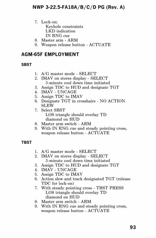
AGM-65F EMPLOYMENT
SBST
1. A/G master mode - SELECT2. IMAV on stores display - SELECT
3-minute cool down time initiated3. Assign TDC to HUD and designate TGT4. IMAV - UNCAGE5. Assign TDC to IMAV6. Designate TGT in crosshairs - NO ACTION
SLEW7. Select SBST
LOS triangle should overlay TDdiamond on HUD
8. Master arm switch - ARM9. With IN RNG cue and steady pointing cross,
weapon release button - ACTUATE
TBST
1. A/G master mode - SELECT2. IMAV on stores display - SELECT
3-minute cool down time initiated3. Assign TDC to HUD and designate TGT4. IMAV - UNCAGE5. Assign TDC to IMAV6. Action slew and track designated TGT (release
TDC for lock-on)7. With steady pointing cross - TBST PRESS
LOS triangle should overlay TDdiamond on HUD
8. Master arm switch - ARM9. With IN RNG cue and steady pointing cross,
weapon release button - ACTUATE
NWP 3-22.5-FA18A/B/C/D PG (Rev. A)
93

VISUAL ATTACK
1. A/G master mode - SELECT2. IMAV - SELECT
3-minute cool down time initiated.3. Assign TDC to IMAV4. Desired options - SELECT5. Master arm switch - ARM6. Action slew crosshairs to TGT7. Establish aircraft in wings level attitude during
designate.8. Release TDC9. With IN RNG cue and steady pointing
cross, weapon release button - ACTUATE
NWP 3-22.5-FA18A/B/C/D PG (Rev. A)
94

AGM-65E SIMULATED ATTACK
1. A/G master mode - SELECT2. Master arm switch - SAFE3. SIM option - SELECT
WITH KNOWN TARGET LOCATION
1. Select MAV display:Caged displayFuze option selectedTiming cue 30 secondsMAV LOS triangle on HUD
2. Select UFC and enter LASER code(s)3. Uncage missile - full MAV video4. Assign TDC to sensor5. Designate target:
MAV LOS and TD diamond coincideS appears on MAV display (if TGT designatedwith another sensor, i.e., NAVDSG)When lock-on occurs, gimbal angle symbolreplaced with solid box lock-on cue, S removed
6. Lock-on:Keyhole constraintsLKD indicationIN RNG cue
7. Master arm switch- simulate ARM (do not ARMunless required/desired for chaff/flare utilization)
8. Weapon release button - PRESS
WITH UNKNOWN TARGET LOCATION
1. Select MAV display:Caged displayFuze option selectedTiming cue 30 secondsMAV LOS triangle on HUD
2. Select UFC and enter LASER code(s)3. Uncage missile - full MAV video4. TDC - assign to MAV
NWP 3-22.5-FA18A/B/C/D PG (Rev. A)
95
5. TDC - PRESSScan mode entered, scan slew available.When target detected, missile lock-onautomatic.
6. Lock-on:Keyhole constraintsLKD indicationIN RNG cue
7. Master arm switch - simulate ARM (do not ARMunless required/desired for chaff/flare utilization)
8. Weapon release button - ACTUATE
AFTER SIMULATED ATTACK
NOTE
If master arm switch - ARM is required(chaff/flare) or is inadvertently selected, en-sure master arm switch - SAFE is selectedfollowing simulated attack and prior to dese-lecting SIM.
1. SIM option - DESELECT
NWP 3-22.5-FA18A/B/C/D PG (Rev. A)
96
AGM-65F SIMULATED ATTACK
1. A/G master mode - SELECT2. Master arm switch - SAFE3. SIM option - SELECT
SBST
1. IMAV on stores display - SELECT3-minute cool down time initiated
2. Assign TDC to HUD and designate TGT3. IMAV - UNCAGE4. Assign TDC to IMAV5. Designate TGT in crosshairs - NO ACTION
SLEW6. Select SBST
LOS triangle should overlay TDdiamond on HUD.
7. Master arm switch - simulate ARM (do not ARMunless required/desired for chaff/flare utilization)
8. With IN RNG cue and steady pointing cross,weapon release button - PRESS
TBST
1. IMAV on stores display - SELECT3-minute cool down time initiated
2. Assign TDC to HUD and designate TGT3. IMAV - UNCAGE4. Assign TDC to IMAV5. Action slew and track designated TGT (release
TDC for lock-on)6. With steady pointing cross - TBST PRESS
LOS triangle should overlay TDdiamond on HUD.
7. Master arm switch - simulate ARM (do not ARMunless required/desired for chaff/flare utilization)
8. With IN RNG cue and steady pointing cross,weapon release button - PRESS
NWP 3-22.5-FA18A/B/C/D PG (Rev. A)
97

VISUAL ATTACK
1. IMAV - SELECT3-minute cool down time initiated.
2. Assign TDC to IMAV3. Desired options - SELECT4. Master arm switch - simulate ARM (do not ARM
unless required/desired for chaff/flare utilization)5. Action slew crosshairs to TGT6. Establish aircraft in wings level attitude during
designate7. Release TDC8. With IN RNG cue and steady pointing
cross, weapon release button - PRESS
AFTER SIMULATED ATTACK
NOTE
If master arm switch - ARM is required(chaff/flare) or is inadvertently selected, en-sure master arm switch - SAFE is selectedfollowing simulated attack and prior to dese-lecting SIM.
1. SIM option - DESELECT
NWP 3-22.5-FA18A/B/C/D PG (Rev. A)
98
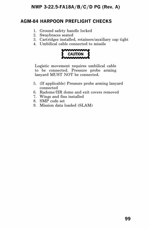
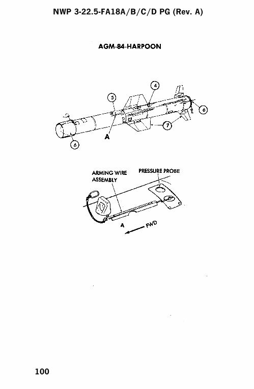
AGM-84 HARPOON PREFLIGHT CHECKS
1. Ground safety handle locked2. Swaybraces seated3. Cartridges installed, retainers/auxiliary cap tight4. Umbilical cable connected to missile
Logistic movement requires umbilical cableto be connected. Pressure probe arminglanyard MUST NOT be connected.
5. (If applicable) Pressure probe arming lanyardconnected
6. Radome/IIR dome and exit covers removed7. Wings and fins installed8. SMP code set9. Mission data loaded (SLAM)
NWP 3-22.5-FA18A/B/C/D PG (Rev. A)
99
NWP 3-22.5-FA18A/B/C/D PG (Rev. A)
100
AGM-84 EMPLOYMENT
INFLIGHT
1. A/G master mode - SELECT
AUX RELEASE
1. Harpoon is indicating H+LKD2. Select ENABLE on AUX release switch3. Master Arm switch - ARM4. Select STORES or RACK/LCHR on selective
jettison select button5. Select HUNG store station on selective jettison
select button6. Press JETT center pushbutton on selective
jettison knob
R/BL LAUNCH MODE
1. Select HPD on STORES display2. Program MODE - R/BL (target position/range
known)3. Select FLT - LOW, MED, HIGH4. Select TERM option - POP, SKIM5. Select SEEK - SML, MED, LRG (seeker search
pattern)6. If LRG selected: LEFT, RIGHT, NORM, NEAR,
FAR (OFFSET priority options)7. Select HPTP if desired (WYPT used is current
WYPT)8. Complete targeting solution (RDR, D/L, FLIR,
NAVDSG)9. Check for IN ZONE cue10. Master arm switch - ARM11. Weapon release button - PRESS
NWP 3-22.5-FA18A/B/C/D PG (Rev. A)
101

BOL LAUNCH MODE
1. Select HPD on STORES display2. Program MODE - BOL (no range to target
known)3. Select FLT - LOW, MED, HIGH4. Select TERM option - POP, SKIM5. Select UFC: SRCH - Seeker enable range
DSTR - Missile destruct rangeBRG - Ordered missile bearing
6. Select HPTP if desired (WYPT used is currentWYPT)
7. Select FXPT if desired (fixed point about thecenter of SRCH and DSTR)
8. Check for IN ZONE cue9. Master arm switch - ARM10. Depress WEAPONS RELEASE button
LOS LAUNCH MODE
1. Select HPD on STORES display
OR
2. Select STEP option to select LOS missile if HPDdegraded
3. LOS cue on STORES display and HP LOS onHUD will flash for 40 seconds
4. Fly straight and level on bearing with intendedtarget
5. Steady LOS or HP LOS cues6. IN ZONE will always be displayed except for
ALT cue conditions7. Master arm switch - ARM8. Weapon release button - PRESS
NWP 3-22.5-FA18A/B/C/D PG (Rev. A)
102
AGM-84 SIMULATED ATTACK
1. A/G master mode - SELECT2. Master arm switch - SAFE3. SIM option - SELECT4. Master arm switch - simulate ARM (do not ARM
unless required/desired for chaff/flare utilization)
R/BL LAUNCH MODE
1. Select HPD on STORES display2. Program MODE - R/BL (target position/range
known)3. Select FLT - LOW, MED, HIGH4. Select TERM option - POP, SKIM5. Select SEEK - SML, MED, LRG (seeker search
pattern)6. If LRG selected: LEFT, RIGHT, NORM, NEAR,
FAR (OFFSET priority options)7. Select HPTP if desired (WYPT used is current
WYPT)8. Complete targeting solution (RDR, D/L, FLIR,
NAVDSG)9. Check for IN ZONE cue10. Weapon release button - PRESS
BOL LAUNCH MODE
1. Select HPD on STORES display2. Program MODE - BOL (no range to target
known)3. Select FLT - LOW, MED, HIGH4. Select TERM option - POP, SKIM5. Select UFC: SRCH - Seeker enable range
DSTR - Missile destruct rangeBRG - Ordered missile bearing
6. Select HPTP if desired (WYPT used is currentWYPT)
7. Select FXPT if desired (fixed point about thecenter of SRCH and DSTR)
8. Check for IN ZONE cue9. Weapon release button - PRESS
NWP 3-22.5-FA18A/B/C/D PG (Rev. A)
103
LOS LAUNCH MODE
1. Select HPD on STORES display
OR
2. Select STEP option to select LOS missile if HPDdegraded
3. LOS cue on STORES display and HP LOS onHUD will flash for 40 seconds
4. Fly straight and level on bearing with intendedtarget
5. Steady LOS or HP LOS cues6. IN ZONE is always displayed except for ALT cue
conditions7. Weapon release button - PRESS
AFTER SIMULATED ATTACK
NOTE
If master arm switch - ARM is required(chaff/flare) or is inadvertently selected, en-sure master arm switch- SAFE is selectedfollowing simulated attack and prior to dese-lecting SIM.
1. SIM option - DESELECT
NWP 3-22.5-FA18A/B/C/D PG (Rev. A)
104

AGM-84E SLAM
Refer to SLAM Pilot Checklist Guide.
NWP 3-22.5-FA18A/B/C/D PG (Rev. A)
105
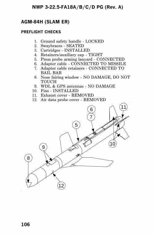
AGM-84H (SLAM ER)
PREFLIGHT CHECKS
1. Ground safety handle - LOCKED2. Swaybraces - SEATED3. Cartridges - INSTALLED4. Retainers/auxiliary cap - TIGHT5. Press probe arming lanyard - CONNECTED6. Adapter cable - CONNECTED TO MISSILE7. Adapter cable retainers - CONNECTED TO
BAIL BAR8. Nose fairing window - NO DAMAGE, DO NOT
TOUCH9. WDL & GPS antennas - NO DAMAGE10. Fins - INSTALLED11. Exhaust cover - REMOVED12. Air data probe cover - REMOVED
8
12
10
116
7
5
9
NWP 3-22.5-FA18A/B/C/D PG (Rev. A)
106

AGM-84H EMPLOYMENT
POSTSTART CHECKS
The following checklist items apply to autonomous orCOOP aircraft with SLMR and DL13.
UFC1. ZTOD - ENTER
Stores Display2. SLMR cue - VERIFY (IN TEST)
If SLAM ER does not inventory (1 SLMR doesnot appear), check umbilical connections. If stillno inventory, turn generators and batteries offfor 10 seconds, reapply power. If SLMR indicatesHOLD, enter ZTOD and verify SLMR XFERand TEST.
BIT Store Station Display3. SLMR timing cue - DECREASING4. DL13 cue - IN TEST
BIT Store Station Display (SLMR Timing E 0)5. SLMR/DL13 cue - VERIFY GO
If SLMR/DL13 do not indicate GO, performSLMR/DL13 BIT.
6. A/G master mode - SELECT
Stores Display7. SLMR option - SELECT/BOX8. DL13 option - SELECT/BOX
SLMR Display9. PP/TOO mode - SELECT10. MSN - VERIFY/SELECT
DL13 Display11. Pod configuration. - VERIFY (PRE, CH/ID,
DLPWR LO, ANT AFT) and coordinate XTMRON/OFF with COOP DL13 aircraft.
12. XTMR (ON/OFF) option - VERIFY VIDEO
NWP 3-22.5-FA18A/B/C/D PG (Rev. A)
107
13. SLMR, DL13, A/G - UNBOX
DL13 POD ONLY POSTSTART CHECKS
BIT Store Station1. DL13 cue - VERIFY GO
If SLMR/DL13 do not indicate GO, performSLMR/DL13 BIT.
2. A/G master mode - VERIFY/SELECT
Stores Display3. DL13 option - SELECT/BOX
DL13 Display4. Pod CONFIG - VERIFY (PRE, CH/ID, DLPWR
LO, ANT AFT) and coordinate XTMR ON/OFFwith SLMR aircraft.
5. XTMR (ON/OFF) option - VERIFY VIDEODSPLYIf video signal is weak or absent, select MPWRHI option.
6. DL13/A/G - UNBOX SV ACQD - VERIFY
AGM-84H EMPLOYMENT
PP OWNSHIP or CO-OP MISSION - LAUNCH AIRCRAFT
1. A/G master mode - SELECT
Stores Display2. SLMR - SELECT/BOX
3. DL13 (if loaded) - SELECT/BOX
DL13 Display4. Pod configuration - VERIFY (PRE, CH/ID,
DLPWR LO, ANT AFT)
SLMR Display5. Mode - SELECT PP
6. MSN - VERIFY/SELECT
7. SV ACQD - VERIFY
NWP 3-22.5-FA18A/B/C/D PG (Rev. A)
108
The number of satellites aquired should be ≥3. Ifthe mission is <30 NM or GPS jamming isexpected, then 4 is recommended.
8. Master arm switch- ARM9. Pickle (at launch point) - PRESS/HOLD10. Master arm switch - OFF
Turn immediately after launch to avoid acollision with SLAM ER.
DL13 Display11. TDC - ASSIGN TO DL13 DISPLAY12. POST display - VERIFY13. TTV - VERIFY COUNTDOWN14. At Data Link Radiate - CALL ″GOOD VIDEO″15. Change FOV - CALL ″GOOD CONTROL″
If there are no HOTAS controls, ensure TDC isassigned and A/G is selected.
16. SLAM ER - CONTROL TO IMPACT17. SLMR/DL13/A/G - UNBOX
PP CO-OP MISSION - CONTROL AIRCRAFT
1. A/G master mode - SELECT
Stores Display2. DL13 option - SELECT/BOX
DL13 Display3. WPN - SELECT SLMR4. DSPLY - SELECT PRE5. CH/ID - SELECT/VERIFY6. COOP - SELECT7. PP Mode - SELECT8. Ensure that SLMR is deselected (If SLMR
loaded)9. TTV - ENTER ON UFC10. ANT - AS REQD11. DLPWR - SELECT HI
Prior To Launch12. DSPLY - SELECT POST13. Start TTV - SELECT AT LAUNCH14. TDC - ASSIGN TO DL13 DISPLAY15. AT data link radiate - CALL ″GOOD VIDEO″16. Change FOV - CALL ″GOOD CONTROL″
NWP 3-22.5-FA18A/B/C/D PG (Rev. A)
109
If there are no HOTAS controls, ensure TDC isassigned and A/G is selected.
17. SLAM ER - CONTROL TO IMPACT18. DL13/A/G - UNBOX
TOO OWNSHIP or CO-OP MISSION - LAUNCH AIRCRAFT
Select SLMR 3 minutes prior to launch to ensure seekercooldown on short range missions.
1. A/G master mode - SELECT
Stores Display2. SLMR - SELECT/BOX3. DL13 (if loaded) - SELECT/BOX
DL13 Display4. Pod configuration - VERIFY (PRE, CH/ID,
DLPWR LO, ANT AFT)
SLMR Display5. Mode - SELECT PP6. MSN - VERIFY/SELECT7. Designate target - VERIFY COORDINATES and
ELEVATION(Recommend NAV DESIGNATE for LAND andRDR LOCK for ASUW)
8. SV ACQD - VERIFYThe number of satellites aquired should be ≥3. Ifthe mission is <30 nm or GPS jamming isexpected then 4 is recommended.
9. Master arm switch - ARM10. Pickle (at launch point) - PRESS/HOLD11. Master arm switch - SAFE
Turn immediately after launch to avoid acollision with SLAM ER.
DL13 Display12. TDC/DC - ASSIGN TO DL13 DISPLAY13. POST Display - VERIFY14. At data link radiate - CALL ″GOOD VIDEO″15. Change FOV - CALL ″GOOD CONTROL″
If there are no HOTAS controls, ensure TDC isassigned and A/G is selected.
NWP 3-22.5-FA18A/B/C/D PG (Rev. A)
110
16. SLAM ER - CONTROL TO IMPACT17. SLMR/DL13/A/G - UNBOX
TOO CO-OP MISSION - CONTROL AIRCRAFT
1. A/G master mode - SELECT
Stores Display2. DL13 option - SELECT/BOX
DL13 Display3. WPN - SELECT SLMR4. DSPLY - SELECT PRE5. CH/ID - SELECT/VERIFY6. COOP - SELECT7. LAND/ASUW - SELECT8. Ensure that SLMR is deselected (If SLMR is
loaded)9. RTT - ENTER ON UFC10. ANT - AS REQD11. DLPWR - SELECT HI
Prior To Launch12. DSPLY - SELECT POST13. Start TTV - SELECT AT LAUNCH14. TDC - ASSIGN TO DL13 DISPLAY15. AT data link radiate - CALL ″GOOD VIDEO″16. Change FOV - CALL ″GOOD CONTROL″
If there are no HOTAS controls, ensure TDC isassigned and A/G is selected.
17. SLAM ER - CONTROL TO IMPACT18. DL13/A/G - UNBOX
NWP 3-22.5-FA18A/B/C/D PG (Rev. A)
111
AGM-84H SIMULATED ATTACK
PP OWNSHIP or CO-OP MISSION- LAUNCH AIRCRAFT
1. A/G master mode - SELECT
Stores Display2. SIM mode - SELECT/BOX
3. SLMR (TSLR) option - SELECT/BOX
4. DL13 (if loaded) - SELECT/BOX
DL13 Display5. Pod configuration - VERIFY (PRE, CH/ID,
DLPWR LO, ANT AFT)
SLMR Display6. Mode - SELECT PP
7. MSN - VERIFY/SELECT
8. SV ACQD - VERIFYThe number of satellites aquired should be ≥3. Ifthe mission is <30 NM or GPS jamming isexpected then 4 is recommended.
9. MSIM (at launch point) - SELECT
DL13 Display10. TDC/DC - ASSIGN TO DL13 DISPLAY
11. POST display - VERIFY
12. At data link radiate - CALL ″GOOD VIDEO″13. Change FOV - CALL ″GOOD CONTROL″
If there are no HOTAS controls, ensure TDC isassigned and A/G is selected.
14. SLAM ER - CONTROL TO OVERFLY
SLMR Display15. MSIM - UNBOX
If performing additional sim flights, begin at step5 and repeat process. Wait 5 seconds beforeperforming step 16.
16. SLMR/ DL13/ A/G - UNBOX
NWP 3-22.5-FA18A/B/C/D PG (Rev. A)
112
TOO CO-OP MISSION - CONTROL AIRCRAFT
1. A/G master mode - SELECT
Stores Display2. DL13 option - SELECT/BOX
DL13 Display3. WPN - SELECT SLMR4. DSPLY - SELECT PRE5. CH/ID - SELECT/VERIFY6. COOP - SELECT7. LAND/ASUW - SELECT8. Ensure that SLMR is deselected (If SLMR
loaded)9. RTT - ENTER ON UFC10. ANT - AS REQD11. DLPWR - SELECT HI
Prior To or At MISM12. DSPLY - SELECT POST13. Start RTT - SELECT AT MISM14. TDC - ASSIGN TO DL13 DISPLAY15. AT data link radiate - CALL ″GOOD VIDEO″16. Change FOV - CALL ″GOOD CONTROL″
If there are no HOTAS controls, ensure TDC isassigned and A/G is selected.
17. SLAM ER - CONTROL TO OVERFLYIf performing additional sim flights, begin at step4 and repeat process.
18. DL13/ A/G - UNBOX
NWP 3-22.5-FA18A/B/C/D PG (Rev. A)
113
AGM-88 HARM PREFLIGHT CHECKS
1. BRU-32 with LAU-118 installeda. Ground safety handle lockedb. Swaybraces seatedc. Cartridges installed (retainers/auxiliary cap
tight)d. Launcher electrically connected to aircraft
2. Missile:a. SA device - SAFE (arming key installed)b. Umbilical NOT connectedc. Umbilical rod in umbilical fitting and securedd. Wings and fins secured
3. SMP code set4. Aircraft:
a. CLC latching fault indicator - black is good(white is failed)
b. ALQ-126B latching fault indicator - black isgood (white is failed)
NOTE
Fault indicators are considered to be unreli-able with external power or no power on theaircraft. The best method for determiningequipment status is by conducting a BITusing cockpit controls with aircraft power.
c. Check RWR and DECM antennas for damage
NWP 3-22.5-FA18A/B/C/D PG (Rev. A)
114
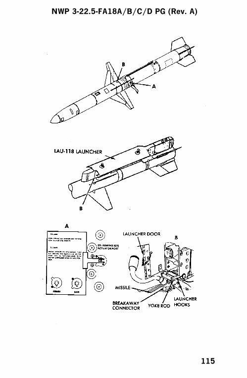
NWP 3-22.5-FA18A/B/C/D PG (Rev. A)
115
AGM-88 EMPLOYMENT
POSTSTART CHECKS
The HARM stray voltage check and umbilical connectioncan be completed only after aircraft power is applied. Thecheck can be performed in any designated area. The missileis not armed until the missile rocket motor has been armed.Arming can only be performed in the forward-firingordnance arming area or on the catapult. Poststart pilotactions should generally be as follows:
1. After engine start and in normal sequence withother avionics operations, turn on the RWR andDECM.
NOTE
On deck at ambient temperatures over 80°F,the RWR and DECM should be limited to 5minutes power on to prevent damage fromoverheating.
2. When able, perform BIT on RWR, DECM, andSMS. HARM BIT cannot be done until theumbilical is connected.
3. Perform HARM stray voltage check and connectumbilical. The missile is still not armed.
4. Enter MC data (target class and type - TOOmode; target number - PB mode).
5. Perform HARM BIT, when able, on all missiles.6. Check SID class for proper software.
INFLIGHT
1. A/G master mode - SELECT2. Weapon - SELECT3. Delivery mode - SELECT
NWP 3-22.5-FA18A/B/C/D PG (Rev. A)
116

TOO Mode
1. SCAN option - SELECTED (if desired)2. LIMIT option - SELECTED (if desired)3. Range known/unknown - SELECTED (as
desired)4. Target class - SELECTED
To select desired priority target -
5. HARM sequence (RAID) button - PRESS
To hand off priority target data to HARM -
6. Cage/uncage button - PRESS
When target is within launch range -
7. Master arm switch - ARM8. Weapon release button - PRESS
PB Mode
1. Target - DESIGNATE2. Pullup option - AS REQUIRED3. Velocity vector - ON ASL4. Master arm switch - ARM
For an on-angle launch, when release cues appear onHUD and A/C RNG cue appears on HARM display
5. Weapon release button - PRESS6. Initiate a pullup while maintaining velocity
vector on ASLa. Release occurs when aircraft pullup cue
intersects velocity vector
NWP 3-22.5-FA18A/B/C/D PG (Rev. A)
117
For a hot pickle launch, when HARM pullup cue iscoincident with the velocity vector on HUD and HRMRNG cue appears on HARM display -
5. Weapon release button - PRESSa. Release occurs at pickle
SP Mode
1. Observe SP target on RWR2. LIMIT option - SELECTED (if desired)
To select desired priority target -
3. HARM sequence (RAID) button - PRESS
When a target is within launch range -
4. Master arm switch - ARM5. Weapon release button - PRESS
SP PLBK Mode
1. Observe self-protect pullback indication on RWR2. HARM OVRD option - DESELECTED
To select desired priority target -
3. HARM sequence (RAID) button - PRESS
When target is within launch range -
4. Master arm switch - ARM5. Weapon release button -PRESS
NWP 3-22.5-FA18A/B/C/D PG (Rev. A)
118
AGM-88 SIMULATED ATTACK
1. A/G master mode - SELECT2. Weapon - SELECT3. Delivery mode - SELECT4. Master arm switch - SAFE5. SIM option - SELECT6. Delivery mode - SELECT
TOO Mode
1. SCAN option - SELECTED (if desired)2. LIMIT option - SELECTED (if desired)3. Range known/unknown - SELECTED (as
desired)4. Target class - SELECTED
To select desired priority target -
5. HARM sequence (RAID) button - PRESS
To hand off priority target data to HARM -
6. Cage/uncage button - PRESS7. Master arm switch - simulate ARM (do not ARM
unless required/desired for chaff/flare utilization)
When target is within launch range -
8. Weapon release button - PRESS
PB Mode
1. Enter target number via UFC2. Target - DESIGNATE3. Pullup option - AS REQUIRED4. Velocity vector - ON ASL5. Master arm switch - simulate ARM (do not ARM
unless required/desired for chaff/flare utilization)
NWP 3-22.5-FA18A/B/C/D PG (Rev. A)
119

For an on-angle launch, when release cues appear onHUD and A/C RNG cue appears on HARM display -
6. Weapon release button - PRESS7. Initiate a pullup while maintaining velocity
vector on ASLa. Simulated release occurs when aircraft pullup
cue intersects velocity vector
For a hot pickle launch, when the HARM pullup cue iscoincident with the velocity vector and HRM RNG cueappears on HARM display -
6. Weapon release button - PRESSa. Simulated release occurs at pickle
SP Mode
1. Observe SP target on RWR2. LIMIT option - SELECTED (if desired)
To select desired priority target -
3. HARM sequence (RAID) button - PRESS
When a target is within launch range -
4. Master arm - simulate ARM (do not ARM unlessrequired/desired for chaff/flare utilization)
5. Weapon release button - PRESS
SP PLBK Mode
1. Observe self-protect pullback indication on RWR2. HARM OVRD option - DESELECTED
To select desired priority target -
3. HARM sequence (RAID) button - PRESS
NWP 3-22.5-FA18A/B/C/D PG (Rev. A)
120
When target is within launch range -
4. Master arm - simulate ARM (do not ARM unlessrequired/desired for chaff/flare utilization)
5. Weapon release button - PRESS
AFTER SIMULATED ATTACK
NOTE
If master arm switch - ARM is required(chaff/flare) or is inadvertently selected, en-sure master arm switch- SAFE is selectedfollowing simulated attack and prior to dese-lecting SIM.
1. SIM option - DESELECT
NWP 3-22.5-FA18A/B/C/D PG (Rev. A)
121

ECM EQUIPMENT
ALR-67 RWR PREFLIGHT
NOTE
With MC OFP 09C or 11C and ALR-67E(V)2OFP 22, functions of the ALR-67 may becontrolled by the dedicated control panel orthe EW display. At aircraft power up, controlis assigned to the EW display. To use thecontrol indicator to operate the ALR-67, theCRTL option on the ALR-67 data subleveldisplay must be deselected (unboxed).
Built-In Test
1. Power button - ACTUATE ON2. Volume, brightness, and intensity controls - SET3. BIT button - ACTUATE
a. Status change tone; first BIT display. Identifythreat library alphanumeric character andcheck that there are no failed units
b. Status change tone; second BIT display (ifrequired)
c. Special alert tone; threat lights come on; thirdBIT display
d. MA tone; threat lights come on; fourth BITdisplay
e. ML tone; threat lights come on; fifth BITdisplay
f. Sixth, seventh, and eighth BIT displays aresequentially presented
NOTE
Actuating ALR-67 BIT pushbutton presentsBIT information only, it does not initiate aBIT. The only way to initiate a BIT is to turnthe system off and back on again.
NWP 3-22.5-FA18A/B/C/D PG (Rev. A)
122
4. Power - AS REQUIRED
Built-In Test (MC OFP 09C or 11C and ALR-67E(V)2 OFP22)
1. Power button - ACTUATE ON2. Volume, brightness, and intensity controls - SET3. Access EW format - accessed by actuating the
EW option on the Tac menu or by actuating thesensor control switch toward the MPCD andtoggling through the display cycle (HSI/SA/EW).
4. Select ALR-67 option.
NOTE
When the BIT option is selected, BIT pagespresented on the EW display are identical tothe BIT pages presented on the azimuthindicator.
5. Select BIT option.a. Status change tone; first BIT display. Identify
threat library alphanumeric character andcheck that there are no failed units
b. Status change tone; second BIT display (ifrequired)
c. Special alert tone; threat lights come on; thirdBIT display
d. MA tone; threat lights come on; fourth BITdisplay
e. ML tone; threat lights come on; fifth BITdisplay
f. Sixth, seventh, and eighth BIT displays aresequentially presented
NOTE
Actuating ALR-67 BIT option presents BITinformation only, it does not initiate a BIT.The only way to initiate a BIT is to turn thesystem off and back on again.
6. ALR-67 trackfile criteria - select via SA sensorsublevel
7. Power - AS REQUIRED
NWP 3-22.5-FA18A/B/C/D PG (Rev. A)
123

RWR BIT FAILURES
SYMBOL STATUSSYSTEM
IMPACT
A Analyzer failure Could be a minor or
major problem
depending on which
components have
failed. The system
does not have to be
shut down.
C Indicator control
panel failure
May not be able to
change selected
options
F Full system
capability
None
L Low band failure System cannot see C
& D band threats
R Quadrant receiver
failure
Threat azimuth data
is not reliable
G Display failure ADU inoperative
T Thermal overload System is
overheating and
should be shutdown
if tactically feasible
S Special failure Cannot see CW
signals
HRM Interface failure Cannot talk to
HARM
NWP 3-22.5-FA18A/B/C/D PG (Rev. A)
124

RWR BIT FAILURES
SYMBOL STATUSSYSTEM
IMPACT
HRMV Interface video line
failure
No real time target
updates to HARM
126 Hard interface
failure
Cannot talk to ALQ-
126B; no jamming
enhancements on the
ADU
126D Degraded interface
failure
No impact on
ALR-67 or ALQ-
126B operation
IBU Interference
blanker unit
ALR-67 look
through time is
reduced. System
response times will
be longer.
NWP 3-22.5-FA18A/B/C/D PG (Rev. A)
125
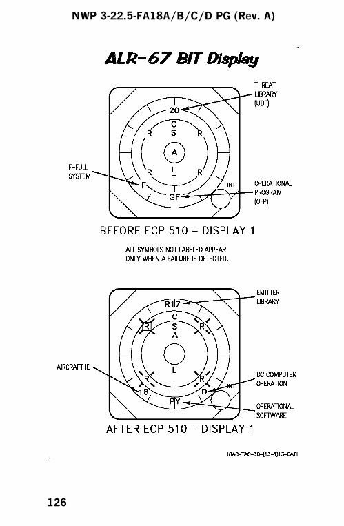
NWP 3-22.5-FA18A/B/C/D PG (Rev. A)
126
ALQ-126 ECM SET PREFLIGHT
1. ECM mode knob - STBYa. STBY light ON 2 - 4 minutesb. STBY light OFF when warmup complete
2. ECM mode knob - BITa. GO light ON when ECM set passes self testb. NO GO light ON if ECM set fails self test
3. ECM mode knob - STBY or OFF (as required)
Do not select REC or RPT/XMIT on thecarrier.
4. JMR option - SELECTa. JMR - BOXEDb. 126B displayed (on line)c. RDY (no line through it)
ALE-39 DISPENSING SYSTEM
F/A-18A/C Preflight
1. External Checks
Dispensing buckets - PRESENT and LOADED
2. Cockpit Checks
a. Check all program settings - AS DESIRED
b. Ensure buckets have been correctly reset to -NUMBER ONE EJECTION TUBES
F/A-18A/C Inflight
1. With weight-off-wheels and ALE-39 payloadselect knob in any position other than OFF, holdthe remote reset switch (located on ANTENNASELECT CONTROL PANEL) to ON for 5
NWP 3-22.5-FA18A/B/C/D PG (Rev. A)
127
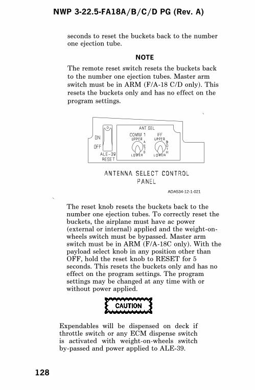
seconds to reset the buckets back to the numberone ejection tube.
NOTE
The remote reset switch resets the buckets back
to the number one ejection tubes. Master arm
switch must be in ARM (F/A-18 C/D only). This
resets the buckets only and has no effect on the
program settings.
The reset knob resets the buckets back to thenumber one ejection tubes. To correctly reset thebuckets, the airplane must have ac power(external or internal) applied and the weight-on-wheels switch must be bypassed. Master armswitch must be in ARM (F/A-18C only). With thepayload select knob in any position other thanOFF, hold the reset knob to RESET for 5seconds. This resets the buckets only and has noeffect on the program settings. The programsettings may be changed at any time with orwithout power applied.
Expendables will be dispensed on deck ifthrottle switch or any ECM dispense switchis activated with weight-on-wheels switchby-passed and power applied to ALE-39.
ADA534-12-1-021
NWP 3-22.5-FA18A/B/C/D PG (Rev. A)
128

F/A-18B/D Preflight1. External Checks
Dispensing buckets - PRESENT and LOADED
2. Cockpit Checks
a. Check all program settings - AS DESIRED
F/A-18B/D Inflight
1. With weight-off-wheels and ALE-39 payloadselect knob in any position other than OFF, holdthe reset knob to RESET for 5 seconds to resetthe buckets back to the number one ejectiontubes.
NOTE
The reset knob resets the buckets back to thenumber one ejection tubes. Master armswitch must be in ARM (F/A-18D only). Thisresets the buckets only and has no effect onthe program settings. The program settingsmay be changed at any time.
ALE-39 PROGRAMMER
C F
B
QTY
B
INT
S
QTY
S
INT
QTY
F
L
A
R
E
INTV
L10 L20
CHAFF L
O
RESET A
DJAMMER
QTY INTV R10 R20
F C
NWP 3-22.5-FA18A/B/C/D PG (Rev. A)
129
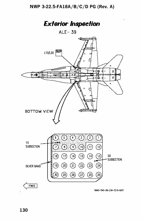
NWP 3-22.5-FA18A/B/C/D PG (Rev. A)
130

ALE-47 DISPENSING SYSTEM
Preflight
1. External Checks
Dispensing buckets - PRESENT and LOADED
2. Internal Checks
a. ALE-47 mode option - STBY MODE
b. Expendable inventory status is reset to theMDF levels - LOAD option selected onPROG format.
c. Arm expendables - ARM format
d. Select bingo levels - BINGO format
NOTE
ALE-47 is in STBY mode while on deck and
during take-off to prevent dispensing during
the time the landing gear is up and locked.
Inflight
1. Check all program settings - AS DESIRED
2. ALE-47 - STBY mode during landing to preventdispensing during the time the landing gear is upand locked.
NWP 3-22.5-FA18A/B/C/D PG (Rev. A)
131

NWP 3-22.5-FA18A/B/C/D PG (Rev. A)
132
ALQ-167 PREFLIGHT
1. Ground safety handles in locked position onloaded stations
2. Sway braces seated3. Cartridges not installed on AN/ALQ-167 station;
cartridge retainers and auxiliary cartridge capstight (all stations)
4. Adapter cable connected to pod5. Suspension hooks open on unloaded stations6. Verify proper code inputs inserted in weapons
insertion panel for stores on stations loaded andverify all unloaded station codes are set asrequired
NWP 3-22.5-FA18A/B/C/D PG (Rev. A)
133
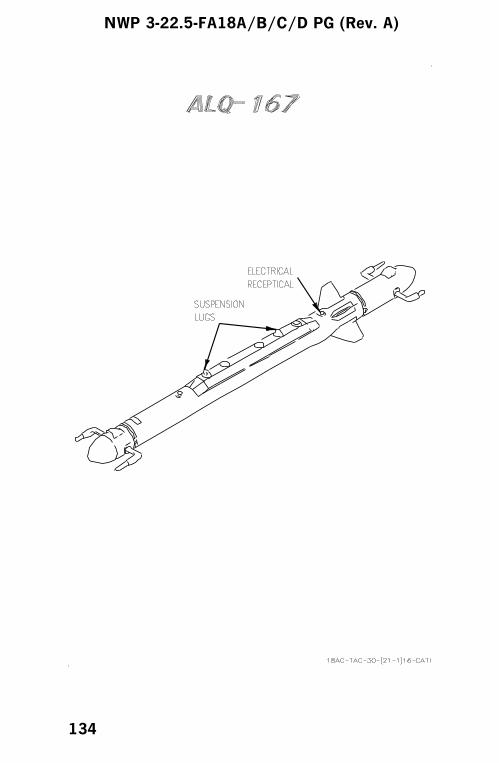
NWP 3-22.5-FA18A/B/C/D PG (Rev. A)
134

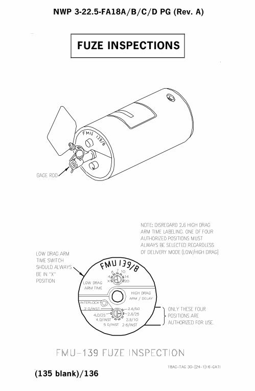
FUZE INSPECTIONS
NWP 3-22.5-FA18A/B/C/D PG (Rev. A)
(135 blank)/136
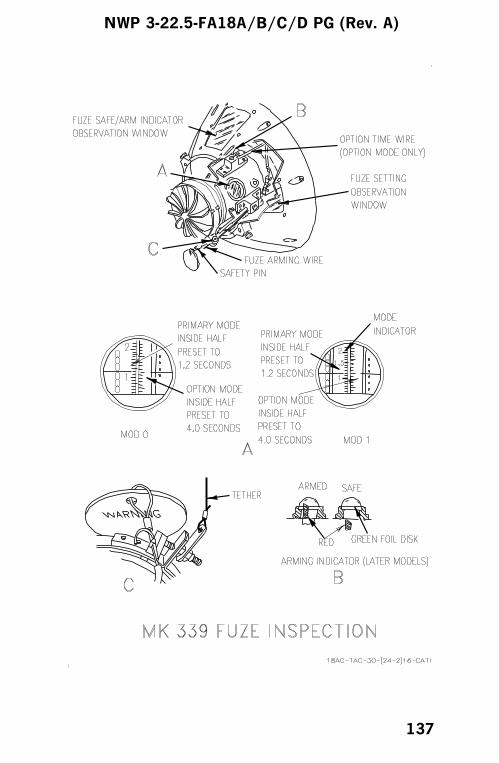
NWP 3-22.5-FA18A/B/C/D PG (Rev. A)
137
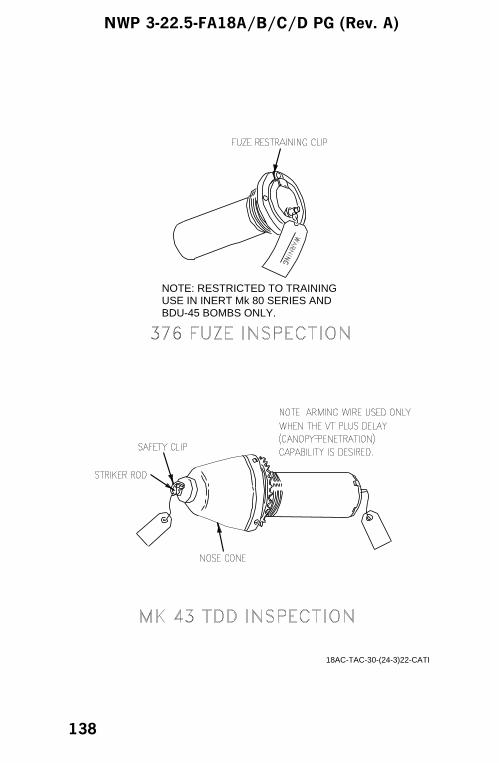
NOTE: RESTRICTED TO TRAINING USE IN INERT Mk 80 SERIES ANDBDU-45 BOMBS ONLY.
18AC-TAC-30-(24-3)22-CATI
NWP 3-22.5-FA18A/B/C/D PG (Rev. A)
138
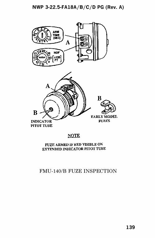
FMU-140/B FUZE INSPECTION
NWP 3-22.5-FA18A/B/C/D PG (Rev. A)
139
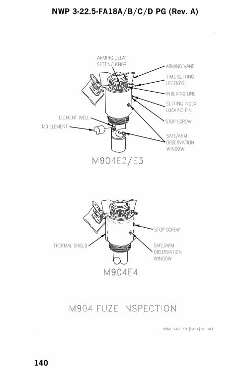
NWP 3-22.5-FA18A/B/C/D PG (Rev. A)
140

NWP 3-22.5-FA18A/B/C/D PG (Rev. A)
141/(142 blank)

ALPHABETICAL INDEX
A
AGM-65E EMPLOYMENT. . . . . . . . . . . . . . . . . . . . . . . . . . . 92
AGM-65E SIMULATED ATTACK . . . . . . . . . . . . . . . . . . . . 95
AGM-65E/F MAVERICK PREFLIGHT CHECKS . . . . . 90
AGM-65F EMPLOYMENT . . . . . . . . . . . . . . . . . . . . . . . . . . . 93
AGM-65F SIMULATED ATTACK . . . . . . . . . . . . . . . . . . . . 97
AGM-84 EMPLOYMENT . . . . . . . . . . . . . . . . . . . . . . . . . . . 101
AGM-84 HARPOON PREFLIGHT CHECKS . . . . . . . . . . 99
AGM-84 SIMULATED ATTACK . . . . . . . . . . . . . . . . . . . . 103
AGM-84E SLAM . . . . . . . . . . . . . . . . . . . . . . . . . . . . . . . . . . . 105
AGM-84H EMPLOYMENT . . . . . . . . . . . . . . . . . . . . . 107, 108
AGM-84H SIMULATED ATTACK . . . . . . . . . . . . . . . . . . 112
AGM-84H (SLAM ER) . . . . . . . . . . . . . . . . . . . . . . . . . . . . . . 106
AGM-88 EMPLOYMENT . . . . . . . . . . . . . . . . . . . . . . . . . . . 116
AGM-88 HARM PREFLIGHT CHECKS . . . . . . . . . . . . . 114
AGM-88 SIMULATED ATTACK . . . . . . . . . . . . . . . . . . . . 119
AGM-154A EMPLOYMENT. . . . . . . . . . . . . . . . . . . . . . . . . . 47
AGM-154A (JSOW) . . . . . . . . . . . . . . . . . . . . . . . . . . . . . . . . . . 46
AIM-7M/H/P EXTERIOR INSPECTION . . . . . . . . . . . . . 22
AIM-9M EXTERIOR INSPECTION . . . . . . . . . . . . . . . . . . 24
AIM-120 EXTERIOR INSPECTION . . . . . . . . . . . . . . . . . . 27
AIR-TO-AIR WEAPONS . . . . . . . . . . . . . . . . . . . . . . . . . . . . 20
AIR-TO-GROUND MISSILES . . . . . . . . . . . . . . . . . . . . . . . 90
AIR-TO-GROUND WEAPONS . . . . . . . . . . . . . . . . . . . . . . . 28
ALE-39 DISPENSING SYSTEM. . . . . . . . . . . . . . . . . . . . . 127
ALE-47 DISPENSING SYSTEM . . . . . . . . . . . . . . . . . . . . 131
ALQ-126 ECM SET PREFLIGHT. . . . . . . . . . . . . . . . . . . . 127
ALQ-167 PREFLIGHT . . . . . . . . . . . . . . . . . . . . . . . . . . . . . . 133
ALR-67 RWR PREFLIGHT . . . . . . . . . . . . . . . . . . . . . . . . . 122
AN/AWW-9B/-13 DATA LINK POD
(Control-Monitor Set) . . . . . . . . . . . . . . . . . . . . . . . . . . . . . . 63
B
BOMBS NONRETARD/RETARD . . . . . . . . . . . . . . . . . . . . 28
NWP 3-22.5-FA18A/B/C/D PG (Rev. A)
143

C
CLUSTER BOMB UNITS (CBU) MK 20
ROCKEYE/CBU-78 GATOR . . . . . . . . . . . . . . . . . . . . . . . 65
COMBAT CHECKS. . . . . . . . . . . . . . . . . . . . . . . . . . . . . . . . . . . 1
D
DESTRUCTORS MK 36/40 DST. . . . . . . . . . . . . . . . . . . . . . 87
E
ECM EQUIPMENT . . . . . . . . . . . . . . . . . . . . . . . . . . . . . . . . 122
F
FUZE INSPECTIONS. . . . . . . . . . . . . . . . . . . . . . . . . . . . . . . 136
G
GBU-12, -16, -10 . . . . . . . . . . . . . . . . . . . . . . . . . . . . . . . . . . . . 35
GBU-24 . . . . . . . . . . . . . . . . . . . . . . . . . . . . . . . . . . . . . . . . . . . . . 37
GBU-31 EMPLOYMENT. . . . . . . . . . . . . . . . . . . . . . . . . . . . . 42
GBU-31 (JDAM) . . . . . . . . . . . . . . . . . . . . . . . . . . . . . . . . . . . . . 41
GBU-31 SIMULATED ATTACK. . . . . . . . . . . . . . . . . . . . . . 45
L
LGTR. . . . . . . . . . . . . . . . . . . . . . . . . . . . . . . . . . . . . . . . . . . . . . . 50
M
M61A1 EXTERIOR INSPECTION . . . . . . . . . . . . . . . . . . . 20
MINES EMPLOYMENT/FLIGHT
DIRECTOR MODE . . . . . . . . . . . . . . . . . . . . . . . . . . . . . . . 86
MINES MK 52/55/56/62/63/65 . . . . . . . . . . . . . . . . . . . . . . . . 79
MK 77 FIRE BOMB . . . . . . . . . . . . . . . . . . . . . . . . . . . . . . . . . 68
NWP 3-22.5-FA18A/B/C/D PG (Rev. A)
144

P
PRACTICE BOMBS MK 76/BDU-33D/B/
MK 106/BDU-48/B . . . . . . . . . . . . . . . . . . . . . . . . . . . . . . . . 78
PYROTECHNICS LUU-2 FLARE/MK 58 MLM . . . . . . . 75
R
ROCKETS . . . . . . . . . . . . . . . . . . . . . . . . . . . . . . . . . . . . . . . . . . 70
S
STORES INFORMATION . . . . . . . . . . . . . . . . . . . . . . . . . . . . 3
T
TALD. . . . . . . . . . . . . . . . . . . . . . . . . . . . . . . . . . . . . . . . . . . . . . 72
W
WALLEYE I SIMULATED ATTACK . . . . . . . . . . . . . . . . . 59
WALLEYE I ER/DL SIMULATED ATTACK
(DUAL AIRCRAFT OPERATION) . . . . . . . . . . . . . . . . . 61
WALLEYE I ER/DL SIMULATED ATTACK
(SINGLE AIRCRAFT OPERATION). . . . . . . . . . . . . . . . 59
WALLEYE I/I ER/DL AND
WALLEYE II/II ER/DL PREFLIGHT CHECKS . . . . 52
WALLEYE I/II EMPLOYMENT . . . . . . . . . . . . . . . . . . . . . 54
WALLEYE I/II ER/DL EMPLOYMENT
(DUAL AIRCRAFT OPERATION) . . . . . . . . . . . . . . . . . 56
WALLEYE I/II ER/DL EMPLOYMENT
(SINGLE AIRCRAFT OPERATION) . . . . . . . . . . . . . . . 55
NWP 3-22.5-FA18A/B/C/D PG (Rev. A)
145/(146 blank)
