tangential grooves in piston crown for swirling action
TRANSCRIPT

COMBUSTION IMPROVEMENT ON A DIRECT INJECTION DIESEL ENGINE BY IMPLEMENTING
TANGENTIAL SWIRLING GROOVES
By: RITESH KUMAR
(121116145) KARTIKPALIWAL
(121116139)
Faculty advisor:-Dr. RAJESH GUPTA

INTRODUCTION
The development of a fuel efficient and less polluting engine is an important aspect of today's requirement in the area of engine research to reduce emissions and improve fuel efficiency.
TURBULENCE
FASTER FLAME TRAVEL
BETTER COMBUSTI
ON
BETTER FUEL
EFFICIENCY
This can be achieved in two ways: • By designing the combustion chamber • Providing the intake system so as to impart
a swirl motion to the incoming air. TURBULENCE
ROTATION
TUMBLE
SQUISH
SWIRL
Piston modification can de done to produce • Swirl MOTION( INDUCTION /COMPRESSION
SWIRL)• SQUISH MOTION• TUMBLE ActionSome of the concerning problems with DI Diesel engines are:
• More Brake Specific fuel Consumption & Lesser brake thermal efficiency: • More Exhaust gases temperature:• Longer ignition delay period:• Pressure rise are less• High emission rate of the oxides of Nitrogen():

HOW ?

SWIRL SQUISH TUMBLE
1 DEFINITIONIt is the rotational motion of the fluid mass within the cylinder
It is the radial flow occurring at the end of the Compression stroke
Squish motion generates a Secondary flow. Rotation occurs about a circumferential axis
2 ADVANTAGE• Homogeneous mixture• rapid spreading of flame front
Homogeneous mixture Homogeneous mixture
3 METHOD OF GENRATION A) INDUCTION SWIRL B )COMPRESSION SWIRL
Generated by the upward movement of the piston toward TDC in compression stroke
By the circumferential grove provided in the center of piston crown
4 TECHNOLOGY USED ASFS“ADVANCED SWIRL FLOW SYSTEM”
ATFT“ADVANCED TUMBLE FLOW TECHNOLOGY”
Fluid Motion in Combustion Chamber

WHY ONLY SWIRL ?

1 FLOW IN CYLINDER
2 Mercury Marine for information obtained from Service Training PublicationsAl piston technology is currently used in applications with up to 420 °C. And piston used nowadays are generally flat crown based pistons in the trucks which lead to improper and insufficient combustion3 http://indian2wheels.blogspot.in/2010/10/what-do-hero-hondas-apdv-asfs-and-atft.htmlNowadays "Advanced Swirl Flow Induction System" which according to my understanding means that the "air+fuel" mixture creates "Swirl" into the combustion chamber in the engine, which should aid better burning of fuel
LITERATURE SURVEY AND REVIEW

PROJECT WORK
• From the experimental investigations and CFD analysis as done by Ballapu Harshavardhan, J.M. Mallikarjuna on two-valve DI engine at an engine speed of 1000 rev/min., using PIV (particle image velocimetry) and CFD with different piston shapes
• We use the case study as THE BASE OF SELECTION OF THE PISTON CROWN DESIGN FOR MAKING TANGENTIAL GROOVES
The observations and comparison parameters for different types of piston shape were categorized on the basis of:• Tumble ratio(TR)• TKE• Evaporation• Velocity
Compared Four different design
Flat crown piston Inclined piston Flat centre bowl piston Inclined Flat bowl piston

A) Comparison of TR and TKE at various crank angles from CFD and PIV analysis with different piston shapes at an engine speed of 1000 rev/minA.Flat Head Piston B. Flat-with-central-
bowl pistonC. Inclined piston D. Inclined piston-
bowl piston
From the above we get the analysis bar chartThe bowl in the piston helps air jet to travel more distance while accelerating, giving rise to higher kinetic energy, higher TR would be dissipated into higher TKE. The TR and TKE in FBP are more by about 58.3 and 21.6% respectively than those of IP.

B) Comparison of in-cylinder velocity vector plots with FP, FBP, IP AND IBP
• It may be because of the bowl in the piston which would create a strong vortex motion throughout the compression stroke .
• This strong vortex motion enhances the mixing and makes the mixture almost uniform.
• the central bowl in piston tries to confine the vortex in it.
• Secondly greater cylinder space leads to higher angular velocity of the vortex.
• However, increased dissipation of vortex in case of FBP as compared To FP engine leads to higher turbulence
• Therefore, it is concluded that, in case of IBP, the mixture distribution and range of TR are much better as compared
to those of IP.
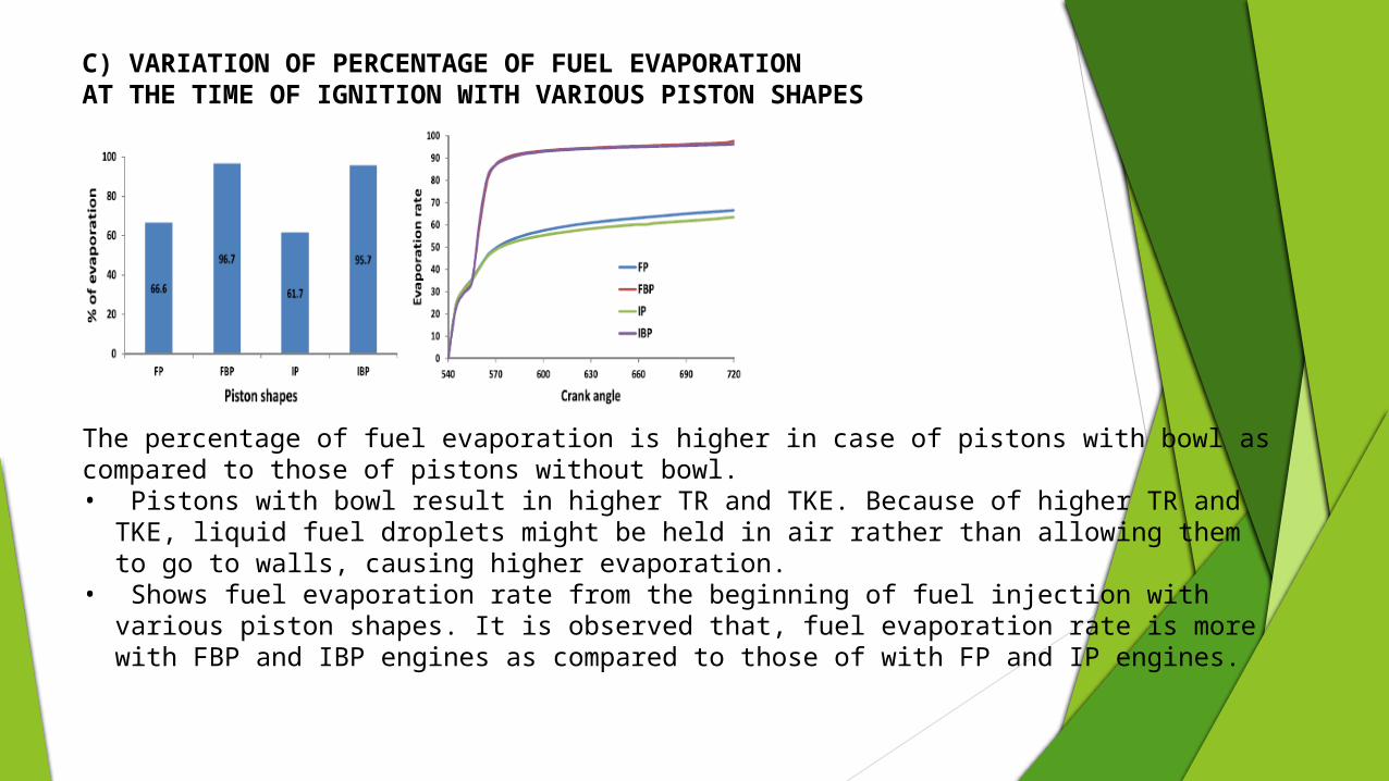
C) VARIATION OF PERCENTAGE OF FUEL EVAPORATIONAT THE TIME OF IGNITION WITH VARIOUS PISTON SHAPES
The percentage of fuel evaporation is higher in case of pistons with bowl as compared to those of pistons without bowl. • Pistons with bowl result in higher TR and TKE. Because of higher TR and TKE, liquid fuel
droplets might be held in air rather than allowing them to go to walls, causing higher evaporation.
• Shows fuel evaporation rate from the beginning of fuel injection with various piston shapes. It is observed that, fuel evaporation rate is more with FBP and IBP engines as compared to those of with FP and IP engines.

CONCLUSIONHence from above case study it is clear that flat bowl piston is best in all casesHence we select flat crown piston with centre bowl as our piston design
FLAT HEAD CENTRE BOWL PISTON
VELOCITY VECTOR
The flat-with-center-bowl piston engine gives higher in cylinder air velocities at the end of suction stroke as compared to those of other engines with different piston shapes considered. It gives about 12.3% higher in-cylinder air velocity as compared to that of flat piston engine
TR & TKR
The TR and TKE with flat-with-center-bowl piston engine are higher at the time of injection and ignition as compared to other engines with different piston shapes considered. They are about 51.9 and 8.9% higher at 540 CAD and 51.2 and 20.9% respectively as compared to those of flat piston engine.
EVAPORATION RATE
Air-fuel mixing is better (i.e., ER is about one at the spark plug location) in case of pistons with bowl as compared to pistons without bowl
CFD Comparison Of flow pattern in FP and IBP

WHAT WE HAVE DESINGED? &WHY ONLY THIS DESIGN?

OUR DESIGN OF FLAT WITH CENTER BOWL PISTON WITH TANGENTIAL SWIRLING GROOVES
STEPS FOR DESIGNING THE FLAT CROWNED TANGENTIAL GROOVED PISTONS:1 Initially piston with prescribed dimensions was designed i.e. 34cc. or 87.5mm bore.2 Later on tangential swirling grooves were designed over top face i.e. 5.5mm, 6.5mm and 7.5mm.3 Depth of groove is taken 2mm in each case.4 Now the increase in cubic capacity had been observed which is paid by Reducing the hemispherical bowl radius of the piston.
Thus the compression ratio was matched between the modified and conventional engine.

Experimental steps
1. Designing of the tangential groove piston
2. Importing the designed file to AVL fire and doing the in cylinder flow simulation
3. Taking the optimum result
4. Performance, emission and combustion characteristics of engine on AVL FIRE SUITE CFD analysis with diesel fuel and piston with swirling groove of 2mm depth and 5.5 mm width
5. Performance, emission and combustion characteristics of engine with the same approach and piston with swirling groove of 2mm depth and 6.5 mm width.
6. Performance, emission and combustion characteristics of engine with the same approach and piston with swirling groove of 2mm depth and 7.5 mm width.

Conclusions Shapes of the head of piston has a major effect on different parameters of a DI Diesel engine. Different
shapes includes FP, FBP, BP and IBP has its effect on Tumble ratio and TKE. All the changes in head design are mostly for attaining turbulence of flow mixture which causes better air-fuel mixing.
A modified proposed design of tangential swirling groove on piston head having varied depth and 2mm thickness are analyzed on AVL and it has more swirling action as compared to all other piston head design.
This modified head design has major effects on increasing the BSFC, Brake thermal efficiency, pressure inside chamber and outlet air temperature.
Also proper combustion will reduce the emission of toxic gases.
Thus this newly modified design of tangential swirling groove on piston head of a DI diesel engine has major effect on the properties of DI engine.
Future Scope: Utilizing the fossil fuels in efficient manner. Increase in the mileage of DI Engines Use of highly advanced and more efficient automobiles. Reduction of environmental pollution caused by highly toxic gases coming out of
Engines. Economy prospect.
Myers P.S. and Uyehava O.A., “Efficiency, Heat transfer and preignition in I.C.engines, SAE 660130, Vol 75”.
[2]. Yufing Li,et.al., “Effects of combinations and orientation of intake ports on swirl motion in DI diesel engine” SAE paper 2000-01-1823,2000.
[3]. Aikidas A.C et.al., “The effects of intake flow configuration on heat release and heat transfer characteristics of a single cylinder four valve S.I Engine” SAE paper 9102996 [1991].
[4]. Timoney, David J et.al., “ Influence of fuel injection and air motion energy sources on fuel air mixing rates in a DI diesel engine combustion” SAE paper 960035.1996
. [5]. Yub-Yih,et.al.,”Investigation of realizing SDI with high swirl charge in motor cycle e.ngine” International Journal of Energy, issue2, Volume.3, 2009.
[6]. Yan-Liang, et.al., “Studies of Tumbling Motion generated during intake in a Bowl – in –Piston Engine” Journal of Science and Technology, Vol.7, No.1, pp.52-64,1999
. [7]. D.J.Timoey, SAE paper 851543, 1985.
REFRENCE