tas5404q1evm user's guide - ti · display for download. ... c17 c18 c19 gnd gnd pvdd 10uh 7.2a...
TRANSCRIPT
User's GuideSLOU427–October 2015
TAS5404Q1EVM User's Guide
1 IntroductionThis user's guide describes the operation of the TAS5404Q1EVM. The TAS5404Q1EVM utilizes thePurePath Console 3 graphical user interface with the TAS5404Q1EVM plugin.
2 Hardware OverviewThe hardware consists of two pcbs that are soldered together through a dual row connector. The mainboard incorporates a TAS1020B for the USB interface through a micro USB connector. A 3.3-Vdc linearregulator provides 3.3 Vdc for the system. The TAS1020B converts the USB protocol to the appropriateI2C address and data. The audio signals are provided through the 3.5-mm female jacks. There are twojumpers, J3 and J4 to short the two 3.5-mm jacks so only one stereo pair is needed to provide signal to allfour channels of the TAS5404-Q1. Connect the provided USB cable to J9 and the PC. The USB does notprovide audio for this EVM.
The power and speaker connections are through the connectors J8 and J5 with screw terminal that accept#22 awg wire. Use two wires for each power connections.
1SLOU427–October 2015 TAS5404Q1EVM User's GuideSubmit Documentation Feedback
Copyright © 2015, Texas Instruments Incorporated

Hardware Overview www.ti.com
Figure 1. TAS5404Q1EVM (Heatsink removed for clarity)
2 TAS5404Q1EVM User's Guide SLOU427–October 2015Submit Documentation Feedback
Copyright © 2015, Texas Instruments Incorporated

www.ti.com Graphical User Interface and Connecting
3 Graphical User Interface and ConnectingThe Graphical User Interface (GUI) utilizes our Purepath Console 3 (PPC3) platform. Download the GUIfrom http://www.ti.com/tool/PUREPATHCONSOLE.
The TAS5404Q1EVM GUI is downloaded through the PPC3 platform. Any updates will automaticallydisplay for download. Connect the PC to the internet to use this function.
Figure 2 displays the GUI. Connect the GUI to the EVM by clicking the “connect” button at the bottom leftof interface. Upon a successful connection the small circle will turn green and the “connect” button willdisappear.
Figure 2. TAS5404 EVM GUI Home Page
3.1 Register Map PageClick on the "Register Map" button on the Home Page to display the register map of the TAS5404-Q1device. Opening the page reads all registers and populates the registers with the TAS5404-Q1 registerdefaults.
Figure 3 displays the Register Map Page. Click on the register to display the description in the Fieldscolumn. In the Register Map column, the pink values are read only, and the black values can be changedand written to the device. Double click on a black value to change its state and write the value to thedevice. Reference the TAS5404-Q1 datasheet, SLOS918, for complete descriptions of the registers andtheir functions.
Click on the “TAS5404 EVM Home” text above the Register Map column to return the Home page.
3SLOU427–October 2015 TAS5404Q1EVM User's GuideSubmit Documentation Feedback
Copyright © 2015, Texas Instruments Incorporated

Graphical User Interface and Connecting www.ti.com
Figure 3. Register Map Page
3.2 Device Control PageEnter the Device Control Page by clicking on the Device Control box on the Home Page. The page shownby Figure 4 will display. This page has buttons that control certain functions of the TAS5404-Q1 device.
Figure 4. Device Control Page
4 TAS5404Q1EVM User's Guide SLOU427–October 2015Submit Documentation Feedback
Copyright © 2015, Texas Instruments Incorporated
www.ti.com Board Layouts and Schematics
4 Board Layouts and Schematics
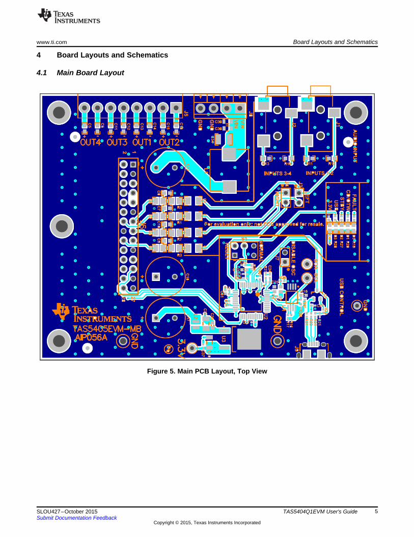
4.1 Main Board Layout
Figure 5. Main PCB Layout, Top View
5SLOU427–October 2015 TAS5404Q1EVM User's GuideSubmit Documentation Feedback
Copyright © 2015, Texas Instruments Incorporated

Board Layouts and Schematics www.ti.com
4.2 TAS5404 Board Layout
Figure 6. Amplifier PCB Layout, Top View
6 TAS5404Q1EVM User's Guide SLOU427–October 2015Submit Documentation Feedback
Copyright © 2015, Texas Instruments Incorporated

www.ti.com Board Layouts and Schematics
Figure 7. Amplifier PCB Layout, Bottom View
7SLOU427–October 2015 TAS5404Q1EVM User's GuideSubmit Documentation Feedback
Copyright © 2015, Texas Instruments Incorporated

4.7µF50V
C340.082µF50V
C352200pF50V
C36
GNDGNDGNDGND
VIN
GND
VIN RANGE = 5.6-18V
4
1
2
3
J8
470µFC17
470µFC18
470µFC19
GND GND
PVDD
10uH 7.2A
L1
10µFC38
0.1µF16V
C37
GND
0.1µF50V
C39
47µF
10V
C40
GND GND GND
3.3V
GND
IN1
OUT3
4
U3TL760M33QKVURQ1
GND
PVDD
L2
10µF
10V
C321µF
6.3V
C33
GND
3.3V
0.1µF16V
C200.1µF16V
C230.1µF16V
C270.1µF16V
C280.1µF16V
C290.1µF16V
C30
Green
2 1
D4
220
R9
GND
5
4
1
2
3
6
7
8
J5
TP2
GND
TP1
GND
GND GND
4.99kR16
4.99kR17
27.4
R24 27.4
R23
1.50kR22
47pFC22
47pFC21
GND
3
1
2
Q115.0k
R21
100pFC25
GND GND
GND
3.3V
GNDSDA
SCL
10.0k
R18
GND
R10
0
R15
3.3V
3.3V
3.3V 3.3V
GND
3.3V
3.3V
5V-USB1
PUR
DPDM
0.1µF16V
C31
0.1µF16V
C26
GND
3.3V
100kR26
GND
GND
A01
A12
A23
VSS4
SDA5
SCL6
WP7
VCC8
U1
24LC512-I/ST
(0xA0)
TP5
GND
6
4
5
13
S1
GND
TP3
SCL
TP4
SDA
3.09k
R25
1000pF
C24
1
2
J7
DISABLE OSC
100kR29
3.3V
VCC4
E/D1
GND2
OUT3
6MHz
Y1
GND
SCLSDA
OrangeD2 STANDBY
RedD5 FAULT
470
R19
470
R20
470
R27
FAULT
CLIP/OTW
STBY
3.3V
RedD1 CLIP/OTW
BlueD3 USB-LOCK
470
R28USB-LOCK
RESET-USB
3
2
1
J2
IN3/4
1200pFC7
1200pFC8
GND GND
3
2
1
J1
IN1/2
49.9kR11
49.9kR12
GND GND
0.47µF
C1
0.47µF
C2
499
R1
499
R5
499
R2
499
R6
GND
IN1
IN2
GND GND
GND GND
GND
49.9kR13
49.9kR14
1200pFC10
1200pFC9
0.47µF
C3
0.47µF
C4
499
R3
499
R7
499
R4
499
R8
IN3
IN4 1
2
J4
PVDD
SCLSDAFAULT
CLIP/OTW
STBY
IN4IN2
IN3
IN1
OUT2+OUT2-
GND GND
OUT1+OUT1-OUT2+OUT2-
0.01µF
C16
0.01µF
C15
0.01µF
C14
0.01µF
C13
0.01µF
C12
0.01µF
C11
0.01µF
C6
0.01µF
C5
GND
1
2
J3
3.3V
OUT4-OUT4+
OUT3-OUT3+
OUT1+OUT1-
OUT4-OUT4+
OUT3-OUT3+
TP6
3.3V
3.3V
1
3
5 6
4
2
7
9 10
8
1211
1413
1615
1817
2019
2221
2423
2625
2827
J6
DNP
DNP
VBUS1
D-2
D+3
ID4
GND5
67
89
J9USB-IN
PLLFILO1
AVDD2
MCLKI3
DVSS4
PUR5
DP6
DM7
DVDD8
MRESET9
TEST10
EXTEN11
RSTO12
P3-013
P3-114
P3-2/XINT15
DVSS16
P3-317
P3-418
P3-519
NC20
DVDD21
NC22
P1-023
P1-124
P1-225
P1-326
P1-427
DVSS28
P1-529
P1-630
P1-731
CSCHNE32
DVDD33
CSYNC35
CDATI36
CSCLK37
CDATO38
MCLKO139
MCLKO240
RESET41
VREN42
SDA43
SCL44
AVSS45
XTALO46
XTALI47
PLLFILI48
CRESET34
U2
TAS1020BPFB
Board Layouts and Schematics www.ti.com
4.3 Main Board Schematic
Figure 8. Main PCB Schematic
8 TAS5404Q1EVM User's Guide SLOU427–October 2015Submit Documentation Feedback
Copyright © 2015, Texas Instruments Incorporated
1µFC27
1µFC28
PVDD
GND GND
GND
GND GND
GND
PVDD
1µFC7
1µF
C8 PVDD
GND249R12
2.2µFC23
GND
20.0kR2
GND
0.1µFC50.1µFC4
0.22µFC11
33.0R1
33.0R3
1 2
3 4
5 6
7 8
9 10
11 12
13 14
15
17
19
21
23
25
27
16
18
20
22
24
26
28
J1
FAULT
CLIP_OTW
STANDBY
IN1_P
IN2_P
IN3_P
IN4_P
IN_M
FAULT
CLIP_OTW
STANDBY
IN1_PIN2_P
IN3_PIN4_P
GND GND
SCLSDA
OUT2-
OUT2+
OUT3-
OUT3+
OUT4-
OUT4+
470pFC15
5.6R4
GND
OUT1_POUT1_M
OUT2_POUT2_M
OUT3_POUT3_M
OUT4_POUT4_M
5.6R5
470pFC16
GND
GND GND
10µH 3.7A
L4
GND GND
GND GND
GND GND
470pFC17
5.6R6
GND
5.6R7
470pFC18
GND GND GND GND GNDPVDD
OUT1-
OUT1+
470pFC20
5.6R9
5.6R8
470pFC19
5.6R10
470pFC21
470pFC22
5.6R11
OUT2-
OUT2+
OUT3-
OUT3+
OUT4-
OUT4+
OUT1-
OUT1+
0.47µFC3
0.47µFC2
0.47µFC10
0.47µFC9
0.47µFC14
0.47µFC13
0.47µFC26
0.47µFC25
0.68µFC24
0.68µFC12
0.68µFC6
0.68µFC1
1µFC29
1µFC30
10µH3.7A
L2
10µH3.7A
L1
10µH3.7A
L3
10µH3.7A
L5
10µH3.7A
L7
10µH3.7A
L6
10µH3.7A
L8
MUTE2
STANDBY4
SCL64
D_BYP5
CLIP_OTW6
IN1_P13
IN2_P15
REXT10
IN_M18
A_BYP11
IN3_P19
IN4_P20
OUT4_P33
OUT4_M34
OUT3_P36
OUT3_M37
CPC_BOT40
CP41
CPC_TOP42
OUT2_P44
OUT2_M45
OUT1_P47
OUT1_M48
OSC_SYNC61
FAULT1
SDA63
I2C_ADDR62
U1A
TAS5404PHD
GND3
GND7
GND8
GND9
GND12
GND14
GND16
GND17
GND21
GND22
GND23
GND24
GND25
GND26
PVDD27
PVDD28
PVDD29
GND30
GND31
GND32
GND35
GND38
GND39
GND43
PVDD52
PVDD53
PVDD54
GND46
GND49
GND50
GND51
GND55
GND56
GND57
GND58
GND59
GND60
U1B
TAS5404PHD
GND
1
2
H9
www.ti.com Board Layouts and Schematics
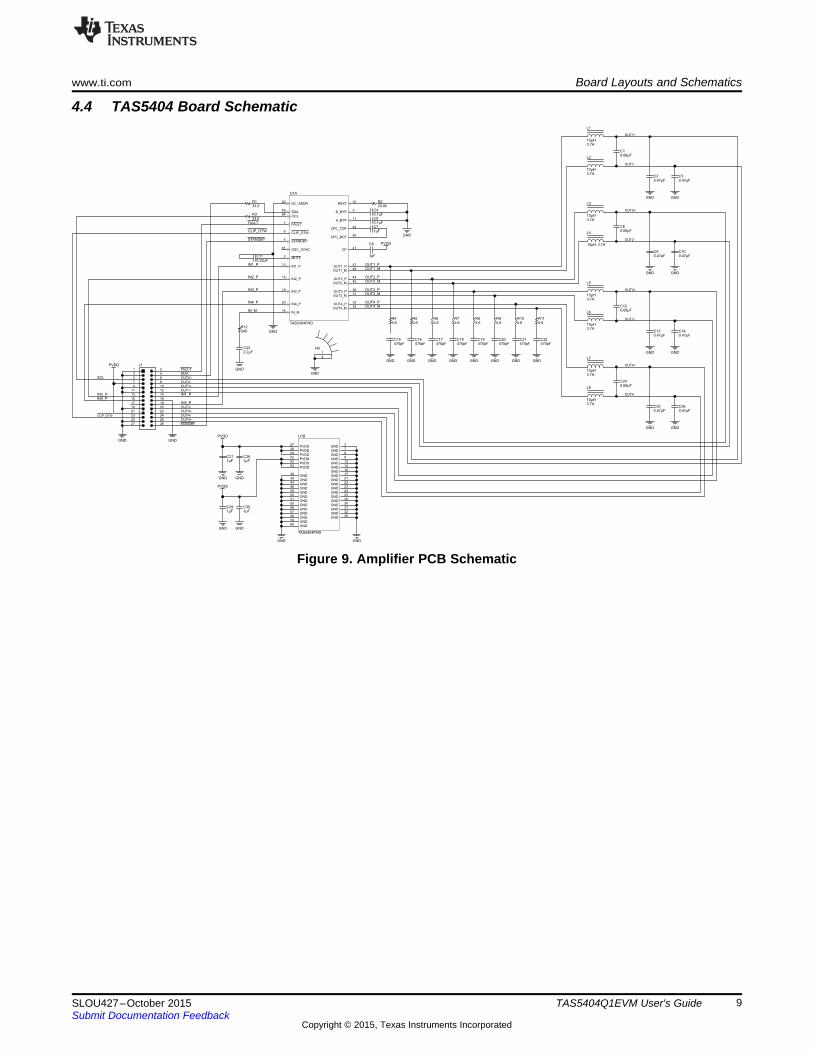
4.4 TAS5404 Board Schematic
Figure 9. Amplifier PCB Schematic
9SLOU427–October 2015 TAS5404Q1EVM User's GuideSubmit Documentation Feedback
Copyright © 2015, Texas Instruments Incorporated
Bill of Materials www.ti.com
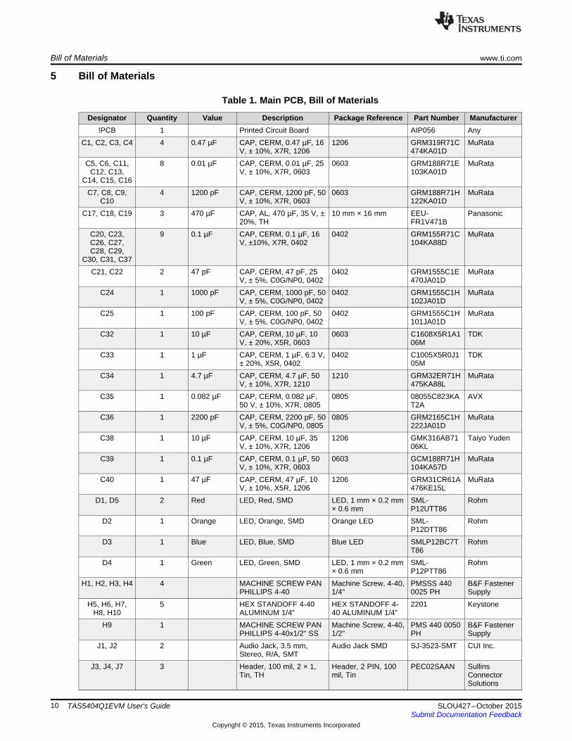
5 Bill of Materials
Table 1. Main PCB, Bill of Materials
Designator Quantity Value Description Package Reference Part Number Manufacturer!PCB 1 Printed Circuit Board AIP056 Any
C1, C2, C3, C4 4 0.47 µF CAP, CERM, 0.47 µF, 16 1206 GRM319R71C MuRataV, ± 10%, X7R, 1206 474KA01D
C5, C6, C11, 8 0.01 µF CAP, CERM, 0.01 µF, 25 0603 GRM188R71E MuRataC12, C13, V, ± 10%, X7R, 0603 103KA01D
C14, C15, C16C7, C8, C9, 4 1200 pF CAP, CERM, 1200 pF, 50 0603 GRM188R71H MuRata
C10 V, ± 10%, X7R, 0603 122KA01DC17, C18, C19 3 470 µF CAP, AL, 470 µF, 35 V, ± 10 mm × 16 mm EEU- Panasonic
20%, TH FR1V471BC20, C23, 9 0.1 µF CAP, CERM, 0.1 µF, 16 0402 GRM155R71C MuRataC26, C27, V, ±10%, X7R, 0402 104KA88DC28, C29,
C30, C31, C37C21, C22 2 47 pF CAP, CERM, 47 pF, 25 0402 GRM1555C1E MuRata
V, ± 5%, C0G/NP0, 0402 470JA01DC24 1 1000 pF CAP, CERM, 1000 pF, 50 0402 GRM1555C1H MuRata
V, ± 5%, C0G/NP0, 0402 102JA01DC25 1 100 pF CAP, CERM, 100 pF, 50 0402 GRM1555C1H MuRata
V, ± 5%, C0G/NP0, 0402 101JA01DC32 1 10 µF CAP, CERM, 10 µF, 10 0603 C1608X5R1A1 TDK
V, ± 20%, X5R, 0603 06MC33 1 1 µF CAP, CERM, 1 µF, 6.3 V, 0402 C1005X5R0J1 TDK
± 20%, X5R, 0402 05MC34 1 4.7 µF CAP, CERM, 4.7 µF, 50 1210 GRM32ER71H MuRata
V, ± 10%, X7R, 1210 475KA88LC35 1 0.082 µF CAP, CERM, 0.082 µF, 0805 08055C823KA AVX
50 V, ± 10%, X7R, 0805 T2AC36 1 2200 pF CAP, CERM, 2200 pF, 50 0805 GRM2165C1H MuRata
V, ± 5%, C0G/NP0, 0805 222JA01DC38 1 10 µF CAP, CERM, 10 µF, 35 1206 GMK316AB71 Taiyo Yuden
V, ± 10%, X7R, 1206 06KLC39 1 0.1 µF CAP, CERM, 0.1 µF, 50 0603 GCM188R71H MuRata
V, ± 10%, X7R, 0603 104KA57DC40 1 47 µF CAP, CERM, 47 µF, 10 1206 GRM31CR61A MuRata
V, ± 10%, X5R, 1206 476KE15LD1, D5 2 Red LED, Red, SMD LED, 1 mm × 0.2 mm SML- Rohm
× 0.6 mm P12UTT86D2 1 Orange LED, Orange, SMD Orange LED SML- Rohm
P12DTT86D3 1 Blue LED, Blue, SMD Blue LED SMLP12BC7T Rohm
T86D4 1 Green LED, Green, SMD LED, 1 mm × 0.2 mm SML- Rohm
× 0.6 mm P12PTT86H1, H2, H3, H4 4 MACHINE SCREW PAN Machine Screw, 4-40, PMSSS 440 B&F Fastener
PHILLIPS 4-40 1/4" 0025 PH SupplyH5, H6, H7, 5 HEX STANDOFF 4-40 HEX STANDOFF 4- 2201 Keystone
H8, H10 ALUMINUM 1/4" 40 ALUMINUM 1/4"H9 1 MACHINE SCREW PAN Machine Screw, 4-40, PMS 440 0050 B&F Fastener
PHILLIPS 4-40x1/2" SS 1/2" PH SupplyJ1, J2 2 Audio Jack, 3.5 mm, Audio Jack SMD SJ-3523-SMT CUI Inc.
Stereo, R/A, SMTJ3, J4, J7 3 Header, 100 mil, 2 × 1, Header, 2 PIN, 100 PEC02SAAN Sullins
Tin, TH mil, Tin ConnectorSolutions
10 TAS5404Q1EVM User's Guide SLOU427–October 2015Submit Documentation Feedback
Copyright © 2015, Texas Instruments Incorporated

www.ti.com Bill of Materials
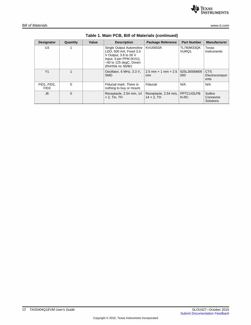
Table 1. Main PCB, Bill of Materials (continued)Designator Quantity Value Description Package Reference Part Number Manufacturer
J5 1 Terminal Block, 3. 5 mm, Terminal Block, 3.5 ED555/8DS On-Shore8-Pos, TH mm, 8-Pos, TH Technology
J8 1 Terminal Block, 6 A, 3.5 14 mm × 8.2 mm × ED555/4DS On-Shoremm Pitch, 4-Pos, TH 6.5 mm Technology
J9 1 Connector, Receptacle, Connector, USB DX4R205JJAR JAEMicro-USB Type AB, R/A, Micro AB 1800 ElectronicsBottom Mount SMT
L1 1 10 uH Inductor, Shielded, 10 10.8 mm × 10 mm DFEG10040D- TokoµH, 7.2 A, 0.027 Ω, SMD 100M
L2 1 300 Ω Ferrite Bead, 300 Ω @ 0806 NFZ2MSM301 MuRata100 MHz, 3.1 A, 0806 SN10L
Q1 1 0.3 V Transistor, NPN, 40V, SOT-23 MMBT2222A Fairchild0.15A, SOT-23 Semiconductor
R1, R2, R3, 8 499 RES, 499, 1%, 0.125 W, 0805 CRCW080549 Vishay-DaleR4, R5, R6, 0805 9RFKEA
R7, R8R9 1 220 RES, 220, 5%, 0.1 W, 0603 CRCW060322 Vishay-Dale
0603 0RJNEAR10, R26, R29 3 100 k RES, 100k Ω, 1%, 0.063 0402 CRCW040210 Vishay-Dale
W, 0402 0KFKEDR11, R12, 4 49.9 k RES, 49.9 k, 1%, 0.1 W, 0603 CRCW060349 Vishay-DaleR13, R14 0603 K9FKEA
R15 1 0 RES, 0, 5%, 0.1 W, 0603 0603 CRCW060300 Vishay-Dale00Z0EA
R16, R17 2 4.99 k RES, 4.99k Ω, 1%, 0.063 0402 CRCW04024K Vishay-DaleW, 0402 99FKED
R18 1 10.0 k RES, 10.0 k, 1%, 0.063 0402 CRCW040210 Vishay-DaleW, 0402 K0FKED
R19, R20, 4 470 RES, 470, 5%, 0.1 W, 0603 CRCW060347 Vishay-DaleR27, R28 0603 0RJNEA
R21 1 15.0 k RES, 15.0k Ω, 1%, 0.063 0402 CRCW040215 Vishay-DaleW, 0402 K0FKED
R22 1 1.50 k RES, 1.50k Ω, 1%, 0.063 0402 CRCW04021K Vishay-DaleW, 0402 50FKED
R23, R24 2 27.4 RES, 27.4 Ω, 1%, 0.063 0402 CRCW040227 Vishay-DaleW, 0402 R4FKED
R25 1 3.09 k RES, 3.09k Ω, 1%, 0.063 0402 CRCW04023K Vishay-DaleW, 0402 09FKED
S1 1 Switch, SPDT, On-On, 2 Switch, 7 mm × 4.5 200USP1T1A1 E-SwitchPos, TH mm M2RE
SH1, SH2 2 1 × 2 Shunt, 100 mil, Gold Shunt 969102-0000- 3Mplated, Black DA
TP1, TP2 2 Black Test Point, Multipurpose, Black Multipurpose 5011 KeystoneBlack, TH Testpoint
TP3, TP4 2 Orange Test Point, Miniature, Orange Miniature 5003 KeystoneOrange, TH Testpoint
TP5 1 Black Test Point, Miniature, Black Miniature 5001 KeystoneBlack, TH Testpoint
TP6 1 Red Test Point, Miniature, Red Miniature 5000 KeystoneRed, TH Testpoint
U1 1 EEPROM, 512 KBIT, 400 TSSOP-8 24LC512-I/ST MicrochipKHZ, 8TSSOP
U2 1 TAS1020BP IC, USB Streaming PQFP48 TAS1020BPFB TIFB Controller
11SLOU427–October 2015 TAS5404Q1EVM User's GuideSubmit Documentation Feedback
Copyright © 2015, Texas Instruments Incorporated
Bill of Materials www.ti.com
Table 1. Main PCB, Bill of Materials (continued)Designator Quantity Value Description Package Reference Part Number Manufacturer
U3 1 Single Output Automotive KVU0003A TL760M33QK TexasLDO, 500 mA, Fixed 3.3 VURQ1 InstrumentsV Output, 3.8 to 26 VInput, 3-pin PFM (KVU),–40 to 125 degC, Green(RoHS& no Sb/Br)
Y1 1 Oscillator, 6 MHz, 3.3 V, 2.5 mm × 1 mm × 2.5 625L3I006M00 CTSSMD mm 000 Electrocompon
entsFID1, FID2, 0 Fiducial mark. There is Fiducial N/A N/A
FID3 nothing to buy or mount.J6 0 Receptacle, 2.54 mm, 14 Receptacle, 2.54 mm, PPTC142LFB Sullins
× 2, Tin, TH 14 × 2, TH N-RC ConnectorSolutions
12 TAS5404Q1EVM User's Guide SLOU427–October 2015Submit Documentation Feedback
Copyright © 2015, Texas Instruments Incorporated

www.ti.com Bill of Materials
Table 2. Amplifier PCB, Bill of Materials
Designator Quantity Value Description Package Reference Part Number Manufacturer!PCB1 1 Printed Circuit Board AIP055 AnyC1, C6, C12, 4 0.68 µF CAP, CERM, 0.68 µF, 10 0603 GRM188R71A6 MuRataC24 V, ± 10%, X7R, 0603 84KA61DC2, C3, C9, 8 0.47 µF CAP, CERM, 0.47 µF, 25 0603 GRM188R71E4 MuRataC10, C13, C14, V, ± 10%, X7R, 0603 74KA12DC25, C26C4, C5 2 0.1 µF CAP, CERM, 0.1 µF, 16 V, 0402 GRM155R71C1 MuRata
± 10%, X7R, 0402 04KA88DC7, C8, C27, 6 1 µF CAP, CERM, 1 µF, 50 V, ± 0805 C2012X7R1H10 TDKC28, C29, C30 10%, X7R, 0805 5K125ABC11 1 0.22 µF CAP, CERM, 0.22 µF, 16 0402 GRM155R71C2 MuRata
V, ± 10%, X7R, 0402 24KA12DC15, C16, C17, 8 470 pF CAP, CERM, 470 pF, 50 V, 0603 GRM1885C1H4 MuRataC18, C19, C20, ± 5%, C0G/NP0, 0603 71JA01DC21, C22C23 1 2.2 µF CAP, CERM, 2.2 µF, 10 V, 0805 GRM21BR71A2 MuRata
± 10%, X7R, 0805 25KA01LH1, H5 2 MACHINE SCREW PAN Machine Screw, 4-40, PMS 440 0050 B&F Fastener
PHILLIPS 4-40 × 1/2" SS 1/2" PH SupplyH2, H6 2 Nut, Hex, 1/4" Thick, #4-40 HNSS440 B&F Fastener
SupplyH3, H7 2 Flat Nylon Washer #4 120 Keystone_3348 3348 Keystone
mil x 250 milH4, H8 2 Lock Washer, Internal INTLWSS 004 B&F Fastener
Tooth, #4, Steel SupplyH9 1 Aluminum Heat Sink Bar for Aluminum Heat Sink HEATSINK_TA Texas
TAS54xxEVM Board Bar for TAS54xxEVM S54XXPHD InstrumentsBoards
H10 1 TAS5404Q1EVM-MB Used in PnP output TAS5404Q1EV Texas(AIP055), Mother Board for and some BOM M-MB InstrumentsTAS5404Q1EVM reports
J1 1 Header, 2.54 mm, 14 × 2, Header, 2.54 mm, 14 PRPC014DBAN SullinsGold, R/A, TH × 2, R/A, TH -M71RC Connector
SolutionsL1, L2, L3, L4, 8 10 uH Inductor, Shielded, Metal 7 mm × 6.6 mm DFEG7030D- TokoL5, L6, L7, L8 Composite, 10 µH, 3.7 A, 100M
0.07 Ω, SMDR1, R3 2 33 RES, 33, 5%, 0.063 W, 0402 CRCW040233R Vishay-Dale
0402 0JNEDR2 1 20.0 k RES, 20.0 k, 1%, 0.063 W, 0402 CRCW040220K Vishay-Dale
0402 0FKEDR4, R5, R6, R7, 8 5.6 RES, 5.6, 5%, 0.125 W, 0805 CRCW08055R6 Vishay-DaleR8, R9, R10, 0805 0JNEAR11R12 1 249 RES, 249, 1%, 0.063 W, 0402 CRCW0402249 Vishay-Dale
0402 RFKEDU1 1 Four-Channel Automotive PHD0064B TAS5404PHD Texas
Digital Amplifiers, InstrumentsPHD0064B
FID1, FID2, 0 Fiducial mark. There is Fiducial N/A N/AFID3, FID4, nothing to buy or mount.FID5, FID6
13SLOU427–October 2015 TAS5404Q1EVM User's GuideSubmit Documentation Feedback
Copyright © 2015, Texas Instruments Incorporated

IMPORTANT NOTICE
Texas Instruments Incorporated and its subsidiaries (TI) reserve the right to make corrections, enhancements, improvements and otherchanges to its semiconductor products and services per JESD46, latest issue, and to discontinue any product or service per JESD48, latestissue. Buyers should obtain the latest relevant information before placing orders and should verify that such information is current andcomplete. All semiconductor products (also referred to herein as “components”) are sold subject to TI’s terms and conditions of salesupplied at the time of order acknowledgment.TI warrants performance of its components to the specifications applicable at the time of sale, in accordance with the warranty in TI’s termsand conditions of sale of semiconductor products. Testing and other quality control techniques are used to the extent TI deems necessaryto support this warranty. Except where mandated by applicable law, testing of all parameters of each component is not necessarilyperformed.TI assumes no liability for applications assistance or the design of Buyers’ products. Buyers are responsible for their products andapplications using TI components. To minimize the risks associated with Buyers’ products and applications, Buyers should provideadequate design and operating safeguards.TI does not warrant or represent that any license, either express or implied, is granted under any patent right, copyright, mask work right, orother intellectual property right relating to any combination, machine, or process in which TI components or services are used. Informationpublished by TI regarding third-party products or services does not constitute a license to use such products or services or a warranty orendorsement thereof. Use of such information may require a license from a third party under the patents or other intellectual property of thethird party, or a license from TI under the patents or other intellectual property of TI.Reproduction of significant portions of TI information in TI data books or data sheets is permissible only if reproduction is without alterationand is accompanied by all associated warranties, conditions, limitations, and notices. TI is not responsible or liable for such altereddocumentation. Information of third parties may be subject to additional restrictions.Resale of TI components or services with statements different from or beyond the parameters stated by TI for that component or servicevoids all express and any implied warranties for the associated TI component or service and is an unfair and deceptive business practice.TI is not responsible or liable for any such statements.Buyer acknowledges and agrees that it is solely responsible for compliance with all legal, regulatory and safety-related requirementsconcerning its products, and any use of TI components in its applications, notwithstanding any applications-related information or supportthat may be provided by TI. Buyer represents and agrees that it has all the necessary expertise to create and implement safeguards whichanticipate dangerous consequences of failures, monitor failures and their consequences, lessen the likelihood of failures that might causeharm and take appropriate remedial actions. Buyer will fully indemnify TI and its representatives against any damages arising out of the useof any TI components in safety-critical applications.In some cases, TI components may be promoted specifically to facilitate safety-related applications. With such components, TI’s goal is tohelp enable customers to design and create their own end-product solutions that meet applicable functional safety standards andrequirements. Nonetheless, such components are subject to these terms.No TI components are authorized for use in FDA Class III (or similar life-critical medical equipment) unless authorized officers of the partieshave executed a special agreement specifically governing such use.Only those TI components which TI has specifically designated as military grade or “enhanced plastic” are designed and intended for use inmilitary/aerospace applications or environments. Buyer acknowledges and agrees that any military or aerospace use of TI componentswhich have not been so designated is solely at the Buyer's risk, and that Buyer is solely responsible for compliance with all legal andregulatory requirements in connection with such use.TI has specifically designated certain components as meeting ISO/TS16949 requirements, mainly for automotive use. In any case of use ofnon-designated products, TI will not be responsible for any failure to meet ISO/TS16949.
Products ApplicationsAudio www.ti.com/audio Automotive and Transportation www.ti.com/automotiveAmplifiers amplifier.ti.com Communications and Telecom www.ti.com/communicationsData Converters dataconverter.ti.com Computers and Peripherals www.ti.com/computersDLP® Products www.dlp.com Consumer Electronics www.ti.com/consumer-appsDSP dsp.ti.com Energy and Lighting www.ti.com/energyClocks and Timers www.ti.com/clocks Industrial www.ti.com/industrialInterface interface.ti.com Medical www.ti.com/medicalLogic logic.ti.com Security www.ti.com/securityPower Mgmt power.ti.com Space, Avionics and Defense www.ti.com/space-avionics-defenseMicrocontrollers microcontroller.ti.com Video and Imaging www.ti.com/videoRFID www.ti-rfid.comOMAP Applications Processors www.ti.com/omap TI E2E Community e2e.ti.comWireless Connectivity www.ti.com/wirelessconnectivity
Mailing Address: Texas Instruments, Post Office Box 655303, Dallas, Texas 75265Copyright © 2015, Texas Instruments Incorporated