td-2 - roland reverb this is a very rich sounding reverb with a choice of character. saturator a...
TRANSCRIPT

Owner’s Manual (this document)Read this first. It explains the basic things you need to know in order to use the TD-25.
PDF Manual (download from the Web)
5 Parameter GuideThis explains all parameters of the TD-25.
5 Sound ListThis is a list of the sounds built into the TD-25.
To obtain the PDF manual
1. Enter the following URL in your computer.http://www.roland.com/manuals/
I2. Choose "TD-25" as the product name.
TD-25V-Drums Sound Module Parameter Guide
Copyright © 2015 ROLAND CORPORATION 01
Version 1.10 support
Version Up InformationTD-25 releases new features through firmware updates.Visit http://www.roland.com/support/ and search for “TD-25” and download the latest “TD-25 System Update.”
How to read this manualFunctions added in version 1.10 are indicated by the icon.
Kit Edit . . . . . . . . . . . . . . . . . . . . . . . . . . . . . . . . . . . . . . . . . . . . . . . . 2Basic Operation . . . . . . . . . . . . . . . . . . . . . . . . . . . . . . . . . . . . . 2Choosing the Reverb (Reverb Type) . . . . . . . . . . . . . . . . . . . . 2Adjusting the Reverb (Reverb Level) . . . . . . . . . . . . . . . . . . . 2Adjusting the Kit Volume (Kit Volume) . . . . . . . . . . . . . . . . . . 3Adjusting the Hi-Hat Pedal Volume (Pedal Hi-Hat Volume) 3Adjusting the Cross Stick Volume (Cross Stick Volume) . . . 3Selecting a Multi-Effect (Multi Effects) . . . . . . . . . . . . . . . . . . 4
Editing the Multi-Effect . . . . . . . . . . . . . . . . . . . . . . . . . 4Renaming a Kit (Kit Name) . . . . . . . . . . . . . . . . . . . . . . . . . . . . 5
Undo/Restore . . . . . . . . . . . . . . . . . . . . . . . . . . . . . . . . . . . . . . . . . 5Cancelling Edits to the Kit (UNDO) . . . . . . . . . . . . . . . . . . . . . 5Restoring the Factory-Set Kit (RESTORE CURRENT KIT) . . . . 5
Audio Rec . . . . . . . . . . . . . . . . . . . . . . . . . . . . . . . . . . . . . . . . . . . . . 6Exporting the Recorded Content (EXPORT) . . . . . . . . . . . . . 6
Practicing in Coach Mode . . . . . . . . . . . . . . . . . . . . . . . . . . . . . 6Selecting a Practice Menu . . . . . . . . . . . . . . . . . . . . . . . . . . . . 6Correctly Playing in Time with the Beat (TIME CHECK) . . . . 7Developing Internal Timing Sense (QUIET COUNT) . . . . . . . 7WARM UPS . . . . . . . . . . . . . . . . . . . . . . . . . . . . . . . . . . . . . . . . . 8
Song Menu . . . . . . . . . . . . . . . . . . . . . . . . . . . . . . . . . . . . . . . . . . . 9Changing the Settings of Each Song . . . . . . . . . . . . . . . . . . . 9A-B Repeat Settings . . . . . . . . . . . . . . . . . . . . . . . . . . . . . . . . . . 9
Setup . . . . . . . . . . . . . . . . . . . . . . . . . . . . . . . . . . . . . . . . . . . . . . . . . 10Basic Operation . . . . . . . . . . . . . . . . . . . . . . . . . . . . . . . . . . . . . 10Options . . . . . . . . . . . . . . . . . . . . . . . . . . . . . . . . . . . . . . . . . . . . 11
Adjusting the Display . . . . . . . . . . . . . . . . . . . . . . . . . . . 11Changing the Auto-Off Setting . . . . . . . . . . . . . . . . . . 11Using USB Audio (USB Driver Mode) . . . . . . . . . . . . . . 11
Click . . . . . . . . . . . . . . . . . . . . . . . . . . . . . . . . . . . . . . . . . . . . . . . 11Adjusting the Click . . . . . . . . . . . . . . . . . . . . . . . . . . . . . 11
Trigger Settings . . . . . . . . . . . . . . . . . . . . . . . . . . . . . . . . . . . . . 12Adjusting the Pads (Triggers) . . . . . . . . . . . . . . . . . . . . 12
Hi-Hat Setting . . . . . . . . . . . . . . . . . . . . . . . . . . . . . . . . . . . . . . . 13Adjusting the Hi-Hat . . . . . . . . . . . . . . . . . . . . . . . . . . . . 13
Pad Panning . . . . . . . . . . . . . . . . . . . . . . . . . . . . . . . . . . . . . . . . 13Adjusting the Panning of Each Pad . . . . . . . . . . . . . . . 13
Pad Note Number . . . . . . . . . . . . . . . . . . . . . . . . . . . . . . . . . . . 13Specifying the Note Number of Each Pad . . . . . . . . . . 13
MIDI . . . . . . . . . . . . . . . . . . . . . . . . . . . . . . . . . . . . . . . . . . . . . . . 14MIDI-Related Settings . . . . . . . . . . . . . . . . . . . . . . . . . . 14
Audio . . . . . . . . . . . . . . . . . . . . . . . . . . . . . . . . . . . . . . . . . . . . . . 14Adjusting the Volume of the AUDIO INPUT and USB 14Specifying the TONE Frequencies . . . . . . . . . . . . . . . . 14Audio REC Settings . . . . . . . . . . . . . . . . . . . . . . . . . . . . . 14
Save 1 Kit . . . . . . . . . . . . . . . . . . . . . . . . . . . . . . . . . . . . . . . . . . . 15Saving Just One Kit to a USB Flash Drive . . . . . . . . . . . 15
Load 1 Kit. . . . . . . . . . . . . . . . . . . . . . . . . . . . . . . . . . . . . . . . . . . 15Loading One Kit from a USB Flash Drive . . . . . . . . . . . 15
Load Backup . . . . . . . . . . . . . . . . . . . . . . . . . . . . . . . . . . . . . . . . 16Loading a Backup from a USB Flash Drive . . . . . . . . . 16
Save Backup . . . . . . . . . . . . . . . . . . . . . . . . . . . . . . . . . . . . . . . . 16Backing-Up to a USB Flash Drive . . . . . . . . . . . . . . . . . 16
Delete Backup . . . . . . . . . . . . . . . . . . . . . . . . . . . . . . . . . . . . . . 16Deleting a Backup from a USB Flash Drive . . . . . . . . . 16
USB Memory Info . . . . . . . . . . . . . . . . . . . . . . . . . . . . . . . . . . . . 17Viewing Information About a USB Flash Memory . . . 17
USB Memory Format . . . . . . . . . . . . . . . . . . . . . . . . . . . . . . . . . 17Formatting a USB Flash Drive . . . . . . . . . . . . . . . . . . . . 17
System Info . . . . . . . . . . . . . . . . . . . . . . . . . . . . . . . . . . . . . . . . . 17Viewing Information About the Unit . . . . . . . . . . . . . . 17
Factory Reset . . . . . . . . . . . . . . . . . . . . . . . . . . . . . . . . . . . . . . . 17Restoring the Factory Settings . . . . . . . . . . . . . . . . . . . 17
Multi Effects . . . . . . . . . . . . . . . . . . . . . . . . . . . . . . . . . . . . . . . . . . 18Parameter List . . . . . . . . . . . . . . . . . . . . . . . . . . . . . . . . . . . . . . . 18
Appendices . . . . . . . . . . . . . . . . . . . . . . . . . . . . . . . . . . . . . . . . . . . 22List of Displayed Messages . . . . . . . . . . . . . . . . . . . . . . . . . . . 22
Error Messages . . . . . . . . . . . . . . . . . . . . . . . . . . . . . . . . 22Other Messages . . . . . . . . . . . . . . . . . . . . . . . . . . . . . . . . 22

2
Choosing the Reverb (Reverb Type)
Here you can select the type of reverb that is applied to the drum kit.
Parameter Value
Reverb Type
OFFBOOTHSTUDIO 1STUDIO 2STAGEARENAGATELONG REVERB
Adjusting the Reverb (Reverb Level)
Here you can adjust the amount of reverb.
Basic OperationIn Kit Edit, you can make detailed settings for a drum kit.
1. In the KIT screen, press the [F3] (MENU) button.The EDIT MENU screen appears.
2. Press the [F2] (KIT) button.The KIT EDIT screen appears.
Move pages.Exit from this page.
Parameter
The role of the [INSTRUMENT] knob and [KICK] (ENTER) button are shown.
Use the [INSTRUMENT] knob to change value.
3. Use the [F2] (C) [F3] (A) buttons to move pages.Reverb Type p. 2Reverb Level p. 2Kit Volume p. 3Pedal Hi-Hat Volume p. 3Cross Stick Volume p. 3Multi Effects p. 4Kit Name p. 5
4. Use [INSTRUMENT] knob to change value.
5. In some screens, pressing the [KICK] (ENTER) button takes you to a different screen.
6. Press kit selector to return to the KIT screen.
* Your changes will be saved automatically.
* You can cancel the changes you made to a kit, or return the entire kit to its factory-set condition (p. 5).
Kit Edit
Kit Edit
3
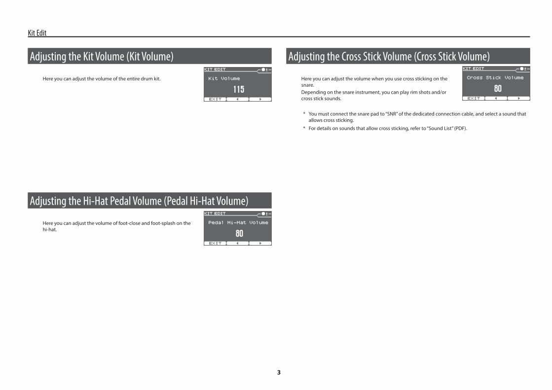
Adjusting the Cross Stick Volume (Cross Stick Volume)
Here you can adjust the volume when you use cross sticking on the snare.Depending on the snare instrument, you can play rim shots and/or cross stick sounds.
* You must connect the snare pad to “SNR” of the dedicated connection cable, and select a sound that allows cross sticking.
* For details on sounds that allow cross sticking, refer to “Sound List” (PDF).
Adjusting the Kit Volume (Kit Volume)
Here you can adjust the volume of the entire drum kit.
Adjusting the Hi-Hat Pedal Volume (Pedal Hi-Hat Volume)
Here you can adjust the volume of foot-close and foot-splash on the hi-hat.

Kit Edit
4
Editing the Multi-Effect
Editing detailed parameters (MFX)
In the Multi Effects screen, press the [KICK] (ENTER) button to access the MFX screen.You can edit detailed parameters for the effect type that you select.
* For details on the parameters of each effect, refer to p. 18.
Specifying the routing and levels (MFX ROUTING)
In the MFX screen, press the [KICK] (ENTER) button to access the MFX ROUTING screen.For each pad, you can specify the amount of multi-effect that is applied, and whether the unprocessed sound is mixed.
Parameter Explanation
DRY+MFX/MFX ONLY
DRY+MFXIn addition to the sound that is processed by the MFX, the unprocessed (DRY) sound is also output.
MFX ONLYOnly the sound that is processed by the MFX is output.Lowering the MFX Level lowers the volume.
Send Level Level sent to MFXMFX Level Output level of the MFX
Selecting a Multi-Effect (Multi Effects)
Here you can select an effect that is applied to the drum kit.
Effect Type
Effect Type ExplanationOFF No effect is applied.STEREO DELAY This is a stereo delay.
REVERSE DELAY This is a reverse delay that adds a reversed sound of the input sound as a delayed sound. A chorus is connected immediately after the reverse delay.
TAPE ECHO Simulates a tape-type echo unit of the past.
CHORUS This is a stereo chorus. A filter is provided so that you can adjust the timbre of the chorus sound.
PHASER This is a stereo phaser. A phase-shifted sound is added to the original sound and modulated.
STEP PHASER This is a stereo phaser. The phaser effect will be varied in stepwise motion.
FLANGER This is a stereo flanger. (The LFO has the same phase for left and right.) It produces a metallic resonance that rises and falls like a jet airplane taking off or landing.
REVERB Adds reverberation to the direct sound, simulating an acoustic space.LONG REVERB This is a very rich sounding reverb with a choice of Character.
SATURATORA saturator which distorts the sound is connected in parallel with a compressor, producing a rougher tonal character and boosting the loudness. This also cuts the low-frequency region of the input audio.
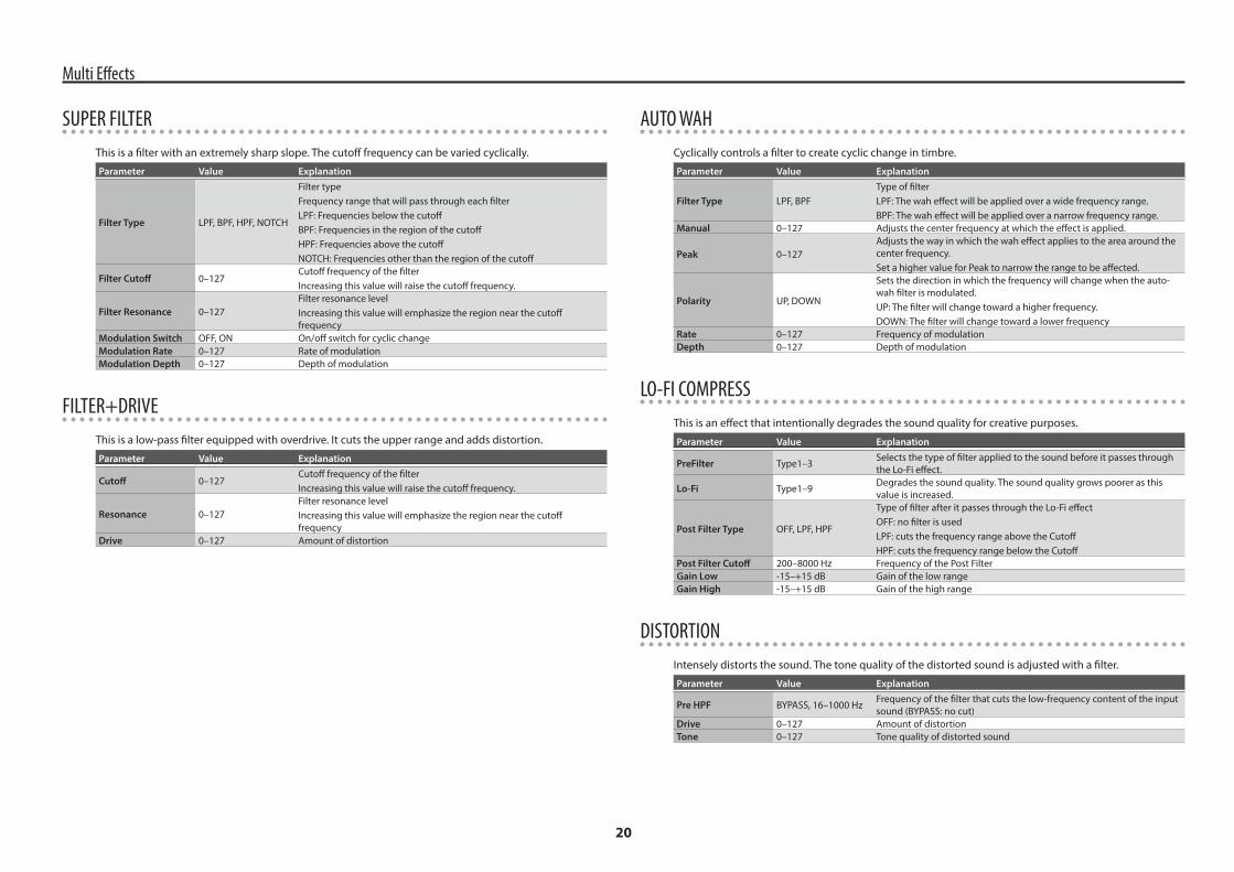
SUPER FILTER This is a filter with an extremely sharp slope. The cutoff frequency can be varied cyclically.
FILTER+DRIVE This is a low-pass filter equipped with overdrive. It cuts the upper range and adds distortion.
AUTO WAH Cyclically controls a filter to create cyclic change in timbre.LO-FI COMPRESS This is an effect that intentionally degrades the sound quality for creative purposes.
DISTORTION Intensely distorts the sound. The tone quality of the distorted sound is adjusted with a filter.
OVERDRIVE Mildly distorts the sound. The tone quality of the distorted sound is adjusted with a filter.
ISOLATOR This is an equalizer which cuts the volume greatly, allowing you to add a special effect to the sound by cutting the volume in varying ranges.
RING MODULATORThis is an effect that applies amplitude modulation (AM) to the input signal, producing bell-like sounds. You can also change the modulation frequency in response to changes in the volume of the sound sent into the effect.
STEP RINGMOD This is a ring modulator that uses a 8-step sequence to vary the frequency at which modulation is applied.
PITCH SHIFT Shifts the pitch of the original sound. This pitch shift can add two pitch shifted sounds to the original sound.
AUTO PAN Cyclically modulates the stereo location of the sound.
* For details on the parameters of each effect, refer to p. 18.

Kit Edit
5
Cancelling Edits to the Kit (UNDO)
You can undo changes you’ve made to a kit.
* The current kit will return to the state in which it was when you selected it.
* If you switch kits, the preceding changes cannot be undone.
1. In the KIT screen, press the [F2] (UNDO) button.The UNDO SELECT screen appears.
2. Press the [F2] (UNDO) button.The confirmation screen appears.
3. Press the [F3] (OK) button.The changes will be undone.If you decide to cancel, press the [F1] (CANCEL) button.
Restoring the Factory-Set Kit (RESTORE CURRENT KIT)Here’s how the current kit can be restored to its factory-set condition.
1. In the KIT screen, press the [F2] (UNDO) button.The UNDO SELECT screen appears.
2. Press the [F3] (RESTORE) button.The RESTORE CURRENT KIT screen appears.
3. Use the [INSTRUMENT] knob to select a factory-set kit.
4. Press the [F3] (RESTORE) button.The confirmation screen appears.
5. Press the [F3] (OK) button.The RESTORE CURRENT KIT operation is executed.If you decide to cancel, press the [F1] (CANCEL) button.
Undo/Restore
Renaming a Kit (Kit Name)
You can rename a kit.
1. In the Kit Name screen, press the [KICK] (ENTER) button.The DRUM KIT NAME screen appears.
Text entry operations
Operation Function[F2] (C) [F3] (A) buttons Move the cursor[INSTRUMENT] knob Change the character[KICK] (ENTER) + [F2] Delete[KICK] (ENTER) + [F3] Insert

6
The TD-25’s Coach mode is a unique set of exercises specifically designed to help build speed, accuracy and stamina, as well as develop better timing skills.Throughout the Coach modes, you will discover that some of them have programmable parameters, allowing you to adapt the functions to your specific needs.
Selecting a Practice Menu1. In the KIT screen, press the [CLICK] button to sound the click.
2. Press the [F1] (COACH) button.The COACH MENU screen appears.
* In version 1.00, press the [F1](T.CHECK) button.
3. Use the [F2] (=) [F3] (?) buttons to select a practice menu item, and then press the [KICK](ENTER) button.Practicing starts as soon as you press the [KICK](ENTER) button.
Menu Item ExplanationTIME CHECK (p. 7) Strengthens your ability to play accurate rhythms.
QUIET COUNT (p. 7) Strengthens your ability to maintain the tempo internally.
WARM UPS (p. 8) Provides warm-up exercises.
Practicing in Coach Mode
Exporting the Recorded Content (EXPORT)
Content that you audio-recorded (TD-25 Owner’s Manual “Recording Your Performance”) can be exported to a USB flash drive.
Export Format: WAV (44.1 kHz, 16-bit)
1. While playing back the audio-recorded data, press the [F3](EXPORT) button.The EXPORT screen appears.Note the name of the file that will be exported.
2. Press the [F3] (EXECUTE) button.The file is exported to the USB flash drive.
* The WAV file is saved in the root (top) folder of the USB flash drive.
Audio Rec
If you don’t want to record the clickIn Setup, turn “Click Record” (p. 14) [OFF].

Practicing in Coach Mode
7
Developing Internal Timing Sense (QUIET COUNT)This mode will help you develop a good sense of time/tempo.For the first few measures, the metronome will sound at the specified volume; over the next few measures, the volume will diminish until it is nearly inaudible. This cycle of several measures will continue until you stop it.
Start practicing
1. Strike the pads in time with the metronome.
5 The metronome will sound during the first few measures. When you reach the last measure during which the metronome will sound, the screen will indicate “Ready.”
5 When the metronome stops sounding, the screen indication will change to “Quiet.” Continue striking the pads during this time.
5 After the Quiet region, the proportion of your strikes that were played at an accurate tempo are shown as a “%” value.
* You can press the [F3] (CLICK) button to make click settings (p. 11).
2. Press the [F1] (EXIT) button to finish the quiet count.
SettingsIn the QUIET COUNT screen, press the [F2] (SETUP) button to access the settings screen.
Parameter Value Explanation
Measures 2, 4, 8, 16 (Measures)
Specify the length (measures) of the interval for which the metronome will alternate between “Sounding” and “Quiet.”
Quiet
Of the measures specified by “Measures,” this setting specifies the length of the measures that will be “Quiet.”
RANDOM The length of the Quiet interval will randomly change each time.
1, 2, 4
Specifies the length (number of measures) of the Quiet interval.
* This setting cannot be longer than half of the Measures value.
* You can press the [KICK] (ENTER) button to make click settings (p. 11).
Correctly Playing in Time with the Beat (TIME CHECK)This mode lets you practice playing accurately along with the metronome.
Start practicing
1. Strike the pad in time with the click.
5 Your strike timing is evaluated for the kick and snare.
5 The time check ends automatically after eight measures, and the score of your performance is shown.
* You can press the [F2] (SETUP) button to change the pads that are evaluated and the number of measures that are scored.
* You can press the [F3] (CLICK) button to make click settings (p. 11).
2. Press the [F1] (EXIT) button to finish the time check.
SettingsIn the TIME CHECK screen, press the [F2] (SETUP) button to access the settings screen.
Parameter Value Explanation
Score
Specifies whether the score will be shown in the screen.
OFFYour performance will not be scored.Only the timing will be checked.
ON(4, 8, 16, 32 meas)
The score will be shown in the screen.You can also specify the number of measures you’ll practice before being scored.
GradeSpecifies the strictness of scoring.EASY NormalHARD Timing will be checked more strictly.
Display 1Display 2
In the screen, select the pad for which a timing graph will be shown.
Gauge
LEFT BEHIND
The left side of the timing graph is shown as BEHIND (late).
LEFT AHEAD
The left side of the timing graph is shown as AHEAD (early).
* You can press the [KICK] (ENTER) button to make click settings (p. 11).
The percentage of your strikes that were played with accurate timing is displayed as a “%” value.
The screen indicates whether your pad strikes match the beat sounded by the click.BEHIND: Behind the beatAHEAD: Ahead of the beat

Practicing in Coach Mode
8
Overall evaluationThis grades your performance at each step, and displays the overall evaluation.
Evaluation (display) EXCELLENT!, VERY GOOD!, GOOD, AVERAGE, START OVER
SettingsIn the WARM UPS screen, press the [F2] (SETUP) button to access the settings screen.
Parameter Value Explanation
Duration
Specifies the time.
5 MINSTime required: 5 minutesChange-Up: 2 minutesTime Check: 3 minutes
10 MINS
Time required: 10 minutesChange-Up: 3 minutesAuto Up/Down: 3 minutesTime Check: 4 minutes
15 MINS
Time required: 15 minutesChange-Up: 5 minutesAuto Up/Down: 5 minutesTime Check: 5 minutes
GradeSpecifies the strictness of scoring.EASY NormalHARD Timing will be checked more strictly.
Change-Up
Step 1: Selects the pattern by which the rhythm will vary during Change-up.
Max Tempo Specifies the upper tempo limit during step 2: Auto Up/Down.
* You can press the [KICK] (ENTER) button to make click settings (p. 11).
WARM UPSIn this mode you’ll successively practice steps 1–3, be graded on your performance at each step, and then receive a final evaluation.You can choose one of three courses, ranging from easy to difficult. You can also adjust the tempo according to your level of skill.
MEMO
After you’ve started WARM UPS, you can press the [F3] (PAUSE) button to pause the WARM UPS.To resume practicing, press the [F3] (START) button once again. If you’re finished with WARM UPS, press the [F1] (STOP) button.
Step 1: Change-UpIn this step, the rhythm type will change every two measures.Starting from half notes, the note values will gradually become shorter, and will then return to half notes; this change in rhythms will be repeated.
Step 2: Auto Up/DownThe tempo will gradually be raised and lowered.The tempo will increase by 1 BPM (beat-per-minute) for each beat until the metronome reaches the upper limit; then the tempo will continue slowing down by 1 BPM until it reaches the initial tempo; this change in tempo will be repeated.
* Auto Up/Down will be executed if Duration is 10 MINS or 15 MINS.
* Auto Up/Down does not let you use the [TEMPO] knob to adjust the tempo.
* The current tempo value will be the lower tempo limit.
MEMO
While practicing, you can press the [F1] (SET MAX) button to specify the current tempo as the upper limit; if you press the [F1] (CLR MAX) button, the upper tempo limit will return to 260.
Step 3:Time CheckAt this step, the accuracy of your playing will be checked against the metronome. You can see in the screen if you are ahead, behind or on the beat.

9
A-B Repeat SettingsThis function lets you repeat a specific region of the song.
1. While the song plays, press the [F3] (MENU) button to access the SONG MENU screen, and then press the [KICK] (ENTER) button.The A-B REPEAT screen appears.
2. At the location where you want to start repeating, press the [F3](SET A) button.
* You can use the [F1] (x) [F2] (y) buttons to move backward or forward in five-second steps. Long-press one of these buttons to rewind or fast-forward.
3. At the location where you want to stop repeating, press the [F3] (SET B) button.Playback repeats between point A and point B.
* You can press the [F3] (RESET) button and reset points A/B.
Canceling A-B repeat
1. Press the [F1] (CANCEL) button.The A-B REPEAT screen closes, and conventional playback resumes.
A B
Changing the Settings of Each Song
In the SONG menu, you can make settings such as volume and loop playback for each audio file.
1. In the USB SONG screen, press the [F3] (MENU) button.The SONG MENU screen appears.
Parameter ExplanationSong Speed Changes the playback speed of the song.
Play TypeLOOP: Plays back repeatedly.ONESHOT: Plays back once and then stops.
Song Volume Adjusts the volume of the audio file.
If you press the [USB SONG] button without connecting a USB flash drive, the internal demo songs are selected.The internal demo songs have the following limitations.
5 The Play Type is fixed at LOOP.
5 The Song Volume is fixed at 100.
In the KIT screen, you can hold down the [USB SONG] button and press the [q/p] button to play the song while remaining in the KIT screen.
Song Menu

10
4. Press the [KICK] (ENTER) button to confirm.The display shows the selected page.
Select parameter.
Use the [INSTRUMENT] knob to change value.
5. Use the [F2] (=) [F3] (?) buttons to select parameter.
6. Use the [INSTRUMENT] knob to change value.
7. In some screens, pressing the [KICK] (ENTER) button takes you to a different screen.
8. Press kit selector to return to the KIT screen.
* Your changes will be saved automatically.
Basic OperationIn Setup, you can make settings that apply to the entire TD-25.
1. In the KIT screen, press the [F3] (MENU) button.The EDIT MENU screen appears.
2. Press the [F3] (SETUP) button.The SETUP screen appears.
Select item.Exit from this page.
Press the [KICK] (ENTER) button to confirm.
3. Use the [F2] (=) [F3] (?) buttons to select item.Options p. 11Click p. 11Trigger Settings p. 12Hi-Hat Setting p. 13Pad Panning p. 13Pad Note Number p. 13MIDI p. 14Audio p. 14
Load 1 Kit p. 15
Save 1 Kit p. 15Load Backup p. 16Save Backup p. 16Delete Backup p. 16USB Memory Info p. 17USB Memory Format p. 17System Info p. 17Factory Reset p. 17
Setup

Setup
11
Click
Here you can specify click settings.
Adjusting the ClickParameter ExplanationBeat Time signaturePattern Click intervalSound ToneVolume VolumePan Panning
Options
Here you can make overall settings for the entire TD-25.
Adjusting the DisplayParameter ExplanationLCD Contrast Adjusts the contrast of the display (Default: 12).LCD Brightness Adjusts the brightness of the display (Default: 8).
Changing the Auto-Off SettingThe TD-25 automatically powers-off when a certain length of time has elapsed since it was last operated or played.With the factory settings, this is set to “4 HOURS.”
* Thirty minutes before the power turns off, a message will appear in the display.
Parameter Explanation
Auto OffOFF The power will not turn off automatically.4 HOURS The power will turn off automatically when four hours have elapsed.
Using USB Audio (USB Driver Mode)This switches the USB driver mode that’s used when the TD-25 is connected to a computer via USB.After changing this setting, you must power the TD-25 off and then on again.
Paramenter Value Operation Driver Explanation
USB Driver
GENERIC USB-MIDI Not requiredChoose this if you want to transfer MIDI messages between the TD-25 and your computer or iPad.
VENDORUSB-AUDIOUSB-MIDI
RequiredChoose this if you want to transfer audio between the TD-25 and your computer.
You can download the dedicated driver for the TD-25 from the Roland website. http://www.roland.com/support/For the operating requirements, refer to the Roland website. The driver program and installation procedure will differ depending on your system. Please carefully read the “Readme.htm” included with the files you downloaded.

Setup
12
Parameter Explanation
Head/Rim Adj
Adjusts how easy it is to trigger a head shot or rim shot (open rim shot) on the pads and drum triggers listed below.If the rim sound is heard when you strike the head strongly, increase this value. If the head sound is heard when you play an open rim shot, decrease this value. If the head sound is heard when you softly play a rim shot, decrease this value.PD series (except PD-8), PDX series, RT-10S, RT-30HR
XStick Thre
Adjusts the playing strength at which to switch between cross stick and rim shot (open rim shot) on the pads and drum triggers listed below.Setting this to a higher value makes it easier to get cross stick sounds. When set to “0,” playing a cross stick produces the open rim shot sound.PD series (except PD-8), PDX series, RT-10S, RT-30HR
Retrig Cancel
This setting prevents double triggering (retriggering) in response to a single strike.In particular for a drum trigger, the waveform is irregular, which can cause triggering to occur at point A in the illustration. This is especially likely to occur as the waveform diminishes. The Retrig Cancel setting detects this irregularity in the waveform and prevents false triggering from occurring.While repeatedly striking the pad or drum trigger, gradually raise this value until retriggering no longer occurs. If this value is too high, notes may drop out when you play successive strikes or a roll.
ScanTime (ms)
Specifies the detection time for the strike signal.While repeatedly striking the pad with the same force, gradually raise this value until stable triggering occurs at the loudest volume. If this value is too high, there will be a longer time from the strike until sound is heard, impairing the performance response.
MaskTime (ms)
If the stick or beater rebounds after a strike and touches the striking surface again, triggering occurs a second time.You can prevent this double triggering by specifying a time immediately following a strike during which further strikes are ignored. While repeatedly striking the pad, raise this value until double triggering does not occur. If this value is too high, notes may drop out when you play successive strikes or a roll.
Pos Detect H Turns strike position detection on/off for the head (H) or rim (R).
* TRIGGER INPUT jacks that support strike position detection: SNARE, RIDE, AUXPos Detect R
ExtNoiseCancel
This setting prevents a drum trigger from being falsely triggered by the sound of a drum that is not equipped with a drum trigger, or by sound or vibration from an external source (Noise Cancel).
* This noise cancel function can be used when a RT-30K or RT-30HR drum trigger is connected to SNR, TOM1, TOM2, or TOM3 of the dedicated connection cable or to the TRIGGER IN jack (AUX) via a Roland-recommended stereo cable.
* The “RT-30H” does not support the Noise Cancel function.
XTalk Cancel
When multiple pads (or acoustic drums equipped with drum triggers) are attached to the same stand, this Crosstalk Cancel setting prevents vibrations produced by a strike from falsely triggering other pads (or drum triggers). For example if pad B is falsely triggered when you strike pad A, you should increase the XTalk Cancel value of pad B until crosstalk no longer occurs. If this value is too high, a note played on pad B might be omitted when pad A and pad B are played simultaneously.
A: Retrigger
Trigger Settings
Here you can specify the type and detailed parameters for each pad that is connected.
Adjusting the Pads (Triggers)Parameter Explanation
TypeSelects the type of pad or drum trigger that is connected.
* If you change the type, the following parameters are changed to values that are appropriate for that type (except for XTalk Cancel).
Sensitivity
You can adjust the sensitivity of the pads to accommodate your personal playing style. This allows you to have more dynamic control over the sound volume, based on how hard you play. Higher sensitivity allows the pad to produce a loud volume even when played softly. Lower sensitivity will keep the pad producing a low volume even when played forcefully.
Threshold
Increase this value if a pad or drum trigger is falsely triggered by vibrations from the environment.If this value is too high, the sound will not be triggered by a soft strike, so you should set it to a lowest level that does not allow false triggering.In the diagram at right, triggering occurs at B, but not at A or C.
Threshold
Rim GainAdjusts the rim sensitivity of the pads and drum triggers listed below.Higher value allows the rim/edge to produce a loud volume even when played softly.PD series, PDX series, CY series, RT-10S, RT-30HR
Curve
Adjust this curve until the response feels as natural as possible.
LINEARLINEAR Playing
Dynamics
VolumeThe standard setting. This produces the most natural correspondence between playing dynamics and volume change.
EXP1EXP2 EXP2EXP1
Volume Volume
Playing Dynamics
Compared to LINEAR, strong dynamics produce a greater change.
LOG1LOG2 LOG2LOG1
Volume Volume
Playing Dynamics
Compared to LINEAR, a soft playing produces a greater change.
SPLINESPLINE
Volume
Playing Dynamics
Extreme changes are made in response to playing dynamics.
LOUD1LOUD2 LOUD2LOUD1
Volume Volume
Playing Dynamics
Very little dynamic response, making it easy to maintain strong volume levels. If you’re using a drum trigger as an external pad, these settings will produce reliable triggering.

Setup
13
Pad Note Number
Specifying the Note Number of Each PadParameter ExplanationKickSnare HeadSnare RimSnare BrushSnare XStickTom1 HeadTom1 RimTom2 HeadTom2 RimTom3 HeadTom3 RimHH Open BowHH Open EdgeHH Close BowHH Close EdgeHH PedalCrash1 BowCrash1 EdgeCrash2 BowCrash2 EdgeRide BowRide EdgeRide BellAUX HeadAUX Rim
Specify the note number that is transmitted and received by each pad.These settings are shared by all of the drum kits.
* If you select a note number that is also assigned to another pad, an “*” is shown at the right of the note number.
Hi-Hat Setting
Adjusting the Hi-HatParameter ExplanationFoot Splash Sens Adjusts how easily the foot splash can be played.
VH-11 CALIBWatch this meter while you adjust the VH-11’s offset.For detail, refer to “Calibrating the Hi-Hat” in the TD-25 Owner’s Manual.
Pad Panning
Adjusting the Panning of Each PadParameter ExplanationKickSnareTom1Tom2Tom3Hi-HatCrash1Crash2RideAUX
Adjust the left/right position of each pad.These settings are shared by all of the drum kits.
Setup
14
Audio
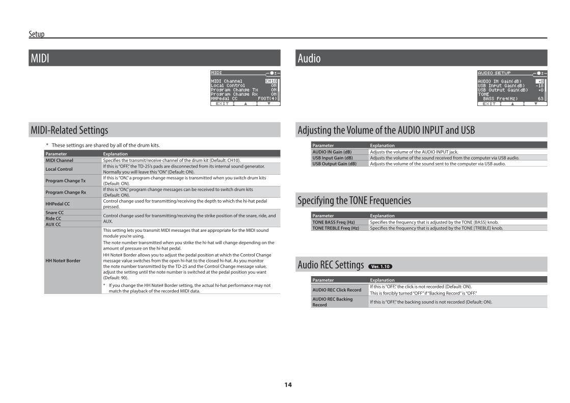
Adjusting the Volume of the AUDIO INPUT and USBParameter ExplanationAUDIO IN Gain (dB) Adjusts the volume of the AUDIO INPUT jack.USB Input Gain (dB) Adjusts the volume of the sound received from the computer via USB audio.USB Output Gain (dB) Adjusts the volume of the sound sent to the computer via USB audio.
Specifying the TONE FrequenciesParameter ExplanationTONE BASS Freq (Hz) Specifies the frequency that is adjusted by the TONE [BASS] knob.TONE TREBLE Freq (Hz) Specifies the frequency that is adjusted by the TONE [TREBLE] knob.
Audio REC SettingsParameter Explanation
AUDIO REC Click RecordIf this is “OFF,” the click is not recorded (Default: ON).This is forcibly turned “OFF” if “Backing Record” is “OFF.”
AUDIO REC Backing Record If this is “OFF,” the backing sound is not recorded (Default: ON).
MIDI
MIDI-Related Settings* These settings are shared by all of the drum kits.
Parameter ExplanationMIDI Channel Specifies the transmit/receive channel of the drum kit (Default: CH10).
Local Control If this is “OFF,” the TD-25’s pads are disconnected from its internal sound generator. Normally you will leave this “ON” (Default: ON).
Program Change Tx If this is “ON,” a program change message is transmitted when you switch drum kits (Default: ON).
Program Change Rx If this is “ON,” program change messages can be received to switch drum kits (Default: ON).
HHPedal CC Control change used for transmitting/receiving the depth to which the hi-hat pedal pressed.
Snare CCControl change used for transmitting/receiving the strike position of the snare, ride, and AUX.Ride CC
AUX CC
HH Note# Border
This setting lets you transmit MIDI messages that are appropriate for the MIDI sound module you’re using.The note number transmitted when you strike the hi-hat will change depending on the amount of pressure on the hi-hat pedal.HH Note# Border allows you to adjust the pedal position at which the Control Change message value switches from the open hi-hat to the closed hi-hat. As you monitor the note number transmitted by the TD-25 and the Control Change message value, adjust the setting until the note number is switched at the pedal position you want (Default: 90).
* If you change the HH Note# Border setting, the actual hi-hat performance may not match the playback of the recorded MIDI data.

Setup
15
Load 1 Kit
Loading One Kit from a USB Flash Drive1. Connect the USB flash drive to the TD-25.
2. In the KIT screen, select the loading-destination kit.
3. In the SETUP screen (p. 10), select “Load 1 Kit.”The LOAD 1 KIT screen appears.
4. Use the [INSTRUMENT] knob to select the kit number that you want to load.
5. Press the [F3] (LOAD) button.The confirmation screen appears.
6. Press the [F3] (OK) button.The settings of the kit loaded from the USB flash drive are overwritten onto the kit that you selected in step 2.If you press the [F1] (EXIT) button, loading will be canceled.
Save 1 Kit
Saving Just One Kit to a USB Flash Drive* Before using a USB flash drive for the first time, you must format it on the TD-25 (p. 17).
1. Connect the USB flash drive to the TD-25.
2. In the KIT screen, select the kit that you want to save.
3. In the SETUP screen (p. 10), select “Save 1 Kit.”The SAVE 1 KIT screen appears.
4. Use the [INSTRUMENT] knob to select the backup destination number (1–999).If you press the [F2] (NEW) button, the lowest number in which no kit is saved will be selected.You can save 999 backups (1–999).
5. Press the [F3] (SAVE) button.The confirmation screen appears.
6. Press the [F3] (OK) button.The settings of the drum kit that you selected in step 2 are saved to the USB flash drive.
* Backup kit files are saved in the Roland/TD-25/Kit folder of the USB flash drive.

Setup
16
4. Press the [F3] (OK) button.
* Before using a USB flash drive for the first time, you must format it on the TD-25 (p. 17).
* Backup files are saved in the Roland/TD-25/Backup folder of the USB flash drive.
Delete Backup
Deleting a Backup from a USB Flash DriveHere’s how to delete a backup that’s been saved on a USB flash drive.
1. Use the [INSTRUMENT] knob to select the backup that you want to delete.
2. Press the [F3] (DELETE) button.
3. Press the [F3] (OK) button.
Load Backup
Loading a Backup from a USB Flash DriveHere’s how to load a backup from a USB flash drive into the TD-25.
NOTE
When you load a backup, all settings in the TD-25 will be erased.
1. Use the [INSTRUMENT] knob to select the backup that you want to load.
2. Press the [F3] (LOAD) button.
3. Press the [F3] (OK) button.
Save Backup
You can save 99 backups (1–99).
Backing-Up to a USB Flash DriveAll settings of the TD-25 can be saved on a USB flash drive.
1. Use the [INSTRUMENT] knob to select the backup destination number.If you press the [F2] (NEW) button, a vacant number is selected.
2. Press the [F3] (SAVE) button.
3. If you want to change the name, press the [F2] (NAME) button, enter the name, and then press the [F1] (EXIT) button.
Operation Function[F2] (C) [F3] (A) buttons Move the cursor[INSTRUMENT] knob Change the character[KICK] (ENTER) + [F2] Delete[KICK] (ENTER) + [F3] Insert

Setup
17
System Info
Viewing Information About the UnitHere’s how to view information about the TD-25.
Parameter ExplanationProgram Version System program version
Factory Reset
Restoring the Factory SettingsThe “Factory Reset” operation returns all data and settings stored in the TD-25 to their factory-set condition.
NOTE
All data and settings in the TD-25 will be lost. If the TD-25 contains any data or settings that you want to keep, you must save them to a USB flash drive before you proceed (p. 16).
1. Press the [F3] (RESET) button.
2. Press the [F3] (OK) button.
USB Memory Info
Viewing Information About a USB Flash MemoryParameter ExplanationBackup All Number of backups that are savedBackup 1 Kit Number of drum kits that are savedAudio File Number of audio files that are savedSize Used Amount of memory used on the USB flash drive
USB Memory Format
Formatting a USB Flash DriveHere’s how to format a USB flash drive.
NOTE
When you execute the Format operation, all data on the USB flash drive will be erased.
1. Press the [F3] (FORMAT) button.
2. Press the [F3] (OK) button.

18
TAPE ECHOSimulates a tape-type echo unit of the past.
Parameter Value ExplanationRate 0–127 Tape speedIntensity 0–127 Amount of echo repeat
CHORUSThis is a stereo chorus. A filter is provided so that you can adjust the timbre of the chorus sound.
Parameter Value Explanation
PreDelay 0.0–100 msec Adjusts the delay time from the direct sound until the chorus sound is heard.
Rate 0–127 Frequency of modulationDepth 0–127 Depth of modulationPhase 0–180 deg Spatial spread of the sound
Filter Type OFF, LPF, HPF
Type of filterOFF: no filter is usedLPF: cuts the high frequency rangeHPF: cuts the low frequency range
Cutoff 200–8000 Hz Frequency when using the filter to cut a specific frequency range
PHASERA phase-shifted sound is added to the original sound and modulated.
Parameter Value Explanation
Mode 4-STAGE, 8-STAGE, 12-STAGE Number of stages in the phaser
Manual 0–127 Adjusts the frequency from which the sound will be modulated.Rate 0–127 Frequency of modulationDepth 0–127 Depth of modulationResonance 0–127 Amount of feedback
STEP PHASERThis is a stereo phaser. The phaser effect will be varied gradually.
Parameter Value Explanation
Mode 4-STAGE, 8-STAGE, 12-STAGE Number of stages in the phaser
Manual 0–127 Adjusts the frequency from which the sound will be modulated.Rate 0–127 Frequency of modulationDepth 0–127 Depth of modulationResonance 0–127 Amount of feedbackStep Rate 0–127 Rate of the step-wise change in the phaser effect
Effect Type PageOFFSTEREO DELAY p. 18REVERSE DELAY p. 18TAPE ECHO p. 18CHORUS p. 18PHASER p. 18STEP PHASER p. 18FLANGER p. 19REVERB p. 19
Effect Type PageLONG REVERB p. 19SATURATOR p. 19SUPER FILTER p. 20FILTER+DRIVE p. 20AUTO WAH p. 20LO-FI COMPRESS p. 20DISTORTION p. 20OVERDRIVE p. 21ISOLATOR p. 21
Effect Type PageRING MODULATOR p. 21STEP RINGMOD p. 21PITCH SHIFT p. 21AUTO PAN p. 21
Parameter List
STEREO DELAYThis is a stereo delay.
Parameter Value Explanation
Time Left 0–1300 msec Adjusts the delay time from when the direct sound begins until the left delay sound is heard.
Time Right 0–1300 msec Adjusts the delay time from when the direct sound begins until the right delay sound is heard.
Feedback -98–+98 % Proportion of the delay sound that is to be returned to the input. Negative (-) settings invert the phase.
Phase Left NORMAL, INVERSE Phase of the left delay soundPhase Right NORMAL, INVERSE Phase of the right delay soundWet Gain Low -15–+15 dB Amount of boost/cut for the effect sound’s lower rangeWet Gain High -15–+15 dB Amount of boost/cut for the effect sound’s upper range
REVERSE DELAYThis is a reverse delay that adds a reversed sound of the input sound as a delayed sound. A chorus is connected immediately after the reverse delay.
Parameter Value ExplanationThreshold 0–127 Volume at which the reverse delay will begin to be applied
DlyTime 0–1300 msec Delay time from when sound is input into the reverse delay until the delay sound is heard
Feedback -98–+98 %Proportion of the delay sound that is to be returned to the input of the reverse delay.Negative (-) settings invert the phase.
Multi Effects

Multi Effects
19
LONG REVERBThis is a very rich sounding reverb with a choice of Character.
Parameter Value ExplanationCharacter 0–5 Type of reverbReverb Time 0–127 Time length of reverberation
PreLPF 16–15000 Hz, BYPASSFrequency of the filter that cuts the high frequency content of the input sound(BYPASS: no cut)
PreHPF BYPASS, 16–15000 Hz Frequency of the filter that cuts the low frequency content of the input sound (BYPASS: no cut)
Pre EQ Freq 200–8000 Hz Frequency of the filter that boosts/cuts a specific frequency region of the input sound
Pre EQ Gain -15–+15 dB Amount of boost/cut produced by the filter at the specified frequency region of the input sound
Depth 0–127 Depth of the effect
HF Damp 16–15000 Hz, BYPASS Frequency at which the high-frequency content of the resonant sound will be cut (BYPASS: no cut)
LF Damp BYPASS, 16–15000 Hz Frequency at which the low-frequency content of the resonant sound will be cut (BYPASS: no cut)
EQ Lo -15–+15 dB Amount of low-range boost/cutEQ Hi -15–+15 dB Amount of high-range boost/cut
SATURATORA saturator which distorts the sound is connected in parallel with a compressor, producing a rougher tonal character and boosting the loudness. This also cuts the low-frequency region of the input audio.
Parameter Value ExplanationSaturator Gain 0–127 Input volume to the saturatorSaturator Drive 0–127 Amount of distortionSaturator Level 0–127 Output volume of the saturatorComp Depth 0–127 Amount of compressionComp Level 0–127 Output volume of the compressorEQ Hi Gain -12–+6 dB Amount of high-range boost/cut
FLANGERThis is a stereo flanger. (The LFO has the same phase for left and right.) It produces a metallic resonance that rises and falls like a jet airplane taking off or landing.
Parameter Value Explanation
PreDelay 0.0–100 msec Adjusts the delay time from when the direct sound begins until the flanger sound is heard.
Rate 0–127 Frequency of modulationDepth 0–127 Depth of modulationPhase 0–180 deg Spatial spread of the sound
Feedback -98–+98 %Adjusts the proportion of the flanger sound that is fed back into the effect.Negative (-) settings will invert the phase.
REVERBAdds reverberation to the direct sound, simulating an acoustic space.
Parameter Value Explanation
Reverb Type ROOM1, ROOM2, STAGE1, STAGE2
Type of reverbROOM1: dense reverb with short decayROOM2: sparse reverb with short decaySTAGE1: reverb with greater late reverberationSTAGE2: reverb with strong early reflections
Reverb Time 0–127 Time length of reverberation
PreDelay 0.0–100 msec Adjusts the delay time from the direct sound until the reverb sound is heard.
HF Damp 200–8000 Hz, BYPASSAdjusts the frequency above which the reverberant sound will be cut.As the frequency is set lower, more of the high frequencies will be cut, resulting in a softer and more muted reverberance (BYPASS: no cut).
Wet Gain Low -15–+15 dB Amount of boost/cut for the effect sound’s lower rangeWet Gain High -15–+15 dB Amount of boost/cut for the effect sound’s upper range
Multi Effects
20
AUTO WAHCyclically controls a filter to create cyclic change in timbre.
Parameter Value Explanation
Filter Type LPF, BPFType of filterLPF: The wah effect will be applied over a wide frequency range.BPF: The wah effect will be applied over a narrow frequency range.
Manual 0–127 Adjusts the center frequency at which the effect is applied.
Peak 0–127Adjusts the way in which the wah effect applies to the area around the center frequency.Set a higher value for Peak to narrow the range to be affected.
Polarity UP, DOWN
Sets the direction in which the frequency will change when the auto-wah filter is modulated.UP: The filter will change toward a higher frequency.DOWN: The filter will change toward a lower frequency
Rate 0–127 Frequency of modulationDepth 0–127 Depth of modulation
LO-FI COMPRESSThis is an effect that intentionally degrades the sound quality for creative purposes.
Parameter Value Explanation
PreFilter Type1–3 Selects the type of filter applied to the sound before it passes through the Lo-Fi effect.
Lo-Fi Type1–9 Degrades the sound quality. The sound quality grows poorer as this value is increased.
Post Filter Type OFF, LPF, HPF
Type of filter after it passes through the Lo-Fi effectOFF: no filter is usedLPF: cuts the frequency range above the CutoffHPF: cuts the frequency range below the Cutoff
Post Filter Cutoff 200–8000 Hz Frequency of the Post FilterGain Low -15–+15 dB Gain of the low rangeGain High -15–+15 dB Gain of the high range
DISTORTIONIntensely distorts the sound. The tone quality of the distorted sound is adjusted with a filter.
Parameter Value Explanation
Pre HPF BYPASS, 16–1000 Hz Frequency of the filter that cuts the low-frequency content of the input sound (BYPASS: no cut)
Drive 0–127 Amount of distortionTone 0–127 Tone quality of distorted sound
SUPER FILTERThis is a filter with an extremely sharp slope. The cutoff frequency can be varied cyclically.
Parameter Value Explanation
Filter Type LPF, BPF, HPF, NOTCH
Filter typeFrequency range that will pass through each filterLPF: Frequencies below the cutoffBPF: Frequencies in the region of the cutoffHPF: Frequencies above the cutoffNOTCH: Frequencies other than the region of the cutoff
Filter Cutoff 0–127Cutoff frequency of the filterIncreasing this value will raise the cutoff frequency.
Filter Resonance 0–127Filter resonance levelIncreasing this value will emphasize the region near the cutoff frequency
Modulation Switch OFF, ON On/off switch for cyclic changeModulation Rate 0–127 Rate of modulationModulation Depth 0–127 Depth of modulation
FILTER+DRIVEThis is a low-pass filter equipped with overdrive. It cuts the upper range and adds distortion.
Parameter Value Explanation
Cutoff 0–127Cutoff frequency of the filterIncreasing this value will raise the cutoff frequency.
Resonance 0–127Filter resonance levelIncreasing this value will emphasize the region near the cutoff frequency
Drive 0–127 Amount of distortion

Multi Effects
21
STEP RINGMODThis is a ring modulator that uses a 8-step sequence to vary the frequency at which modulation is applied.
Parameter Value Explanation
Mode RING MOD, ENV OSCRING MOD: Applies amplitude modulation to the input signalENV OSC: Outputs oscillation corresponding to the input signal
Freq Modify -64–+63 Increases/decreases value for all stepsAttack 0–127 Speed at which the modulation frequency changes between stepsRate 0–127 Rate at which 8-step sequence is to be repeatedFreq Step 1–8 0–127 Frequency of ring modulation at each step
PITCH SHIFTShifts the pitch of the original sound. This pitch shift can add two pitch shifted sounds to the original sound.
Parameter Value ExplanationPitch1 -24–+12 semi Adjusts the pitch of Pitch Shift 1 in semitone steps.Pitch1 Level 0–127 Volume of the Pitch Shift 1 soundPitch2 -24–+12 semi Adjusts the pitch of Pitch Shift 2 in semitone steps.Pitch2 Level 0–127 Volume of the Pitch Shift 2 sound
DlyTime 0–1300 msec Adjusts the delay time from the direct sound until the Pitch Shift sound is heard.
Feedback -98–+98 %Adjusts the proportion of the pitch shifted sound that is fed back into the effect.Negative (-) settings will invert the phase.
Wet Gain Low -15–+15 dB Amount of boost/cut for the effect sound’s lower rangeWet Gain High -15–+15 dB Amount of boost/cut for the effect sound’s upper range
AUTO PANCyclically modulates the stereo location of the sound.
Parameter Value ExplanationRate 0–127 Frequency of the changeDepth 0–127 Depth to which the effect is applied
OVERDRIVEMildly distorts the sound. The tone quality of the distorted sound is adjusted with a filter.
Parameter Value Explanation
Pre HPF BYPASS, 16–1000 Hz Frequency of the filter that cuts the low-frequency content of the input sound (BYPASS: no cut)
Drive 0–127 Amount of distortionTone 0–127 Tone quality of distorted sound
ISOLATORThis is an equalizer which cuts the volume greatly, allowing you to add a special effect to the sound by cutting the volume in varying ranges.
Parameter Value Explanation
Boost/Cut Low -64–+63Boosts and cuts the low frequency ranges.At -64, the sound becomes inaudible. 0 is equivalent to the input level of the sound.
Boost/Cut Mid -64–+63Boosts and cuts the middle frequency ranges.At -64, the sound becomes inaudible. 0 is equivalent to the input level of the sound.
Boost/Cut High -64–+63Boosts and cuts the high frequency ranges.At -64, the sound becomes inaudible. 0 is equivalent to the input level of the sound.
RING MODULATORThis is an effect that applies amplitude modulation (AM) to the input signal, producing bell-like sounds. You can also change the modulation frequency in response to changes in the volume of the sound sent into the effect.
Parameter Value Explanation
Mode RING MOD, ENV OSCRING MOD: Applies amplitude modulation to the input signalENV OSC: Outputs oscillation corresponding to the input signal
Frequency 0–127 Adjusts the frequency at which modulation is applied.
Sensitivity 0–127 Adjusts the amount of frequency modulation applied.
Polarity UP, DOWN Determines whether the frequency modulation moves towards higher frequencies (UP) or lower frequencies (DOWN).

22
Other MessagesMessage Meaning Action
Cannot GROUP MUFFLING. Select INSTRUMENT with same parameter. (MUFFLING or DECAY)
In order for you to turn on the [F2] (GROUP) button and adjust the tom muffling for multiple toms, the muffling parameter of all toms 1–3 must be either MUFFLING or DECAY.
Change the instrument settings so that the muffling parameter of all toms 1–3 is set to either MUFFLING or DECAY.
Clear current TOMS INSTRUMENT assign, and change to preset assign. Press [OK] to Execute.
The instrument assigned to toms 1–3 is cleared, and changes to the preset tom settings.
If you want to change to the preset tom settings, press [F3] (OK). If you decide to cancel, press [F1] (CANCEL).
The modified settings will become effective after power off and restart.
The USB Driver settings take effect when you turn the power of the TD-25 off and on again.
Turn the power of the TD-25 off and on again.
List of Displayed Messages
Error MessagesMessage Meaning Action
Data Damaged! The data on the USB flash drive is damaged. Do not use this file.
Empty Backup! No backup you request on the USB flash drive. —
MIDI Buffer Full!A large amount of MIDI messages were received in a short time, and could not be processed completely.
Confirm that the external MIDI device is properly connected. If the problem persists, reduce the amount of MIDI messages sent to the TD-25.
No empty backup area remains.
There are no empty backup area on the USB flash drive. Delete unneeded backup.
Song is too long! The audio file cannot be played because it is too long.
Play back an audio file that is no larger than 2 GB.
Song is too short! The audio file cannot be played because it is too short.
Play back an audio file that is at least 1 second.Audio files shorter than 1 second might not play.
System Error! A problem has occurred with the internal system.
Contact your dealer or a nearby Roland service center.
System Initialize Data in the TD-25’s memory may be corrupted. Contact your dealer or a nearby Roland service center.
USB drive is too busy. The data could not be read or written in time. Use a USB Flash Memory sold by Roland.
USB Memory Error!The data on the USB flash drive is damaged. Do not use this file.
A USB flash drive the format of which is not supported by TD-25 has been inserted. Format the USB flash drive.
USB Memory Full! There are no empty space on the USB flash drive. Delete unneeded data.
USB memory is not connected! No USB flash drive is in the USB MEMORY port.
Insert a USB flash drive correctly.Use a USB Flash Memory sold by Roland.
No AUDIO REC Data! No recorded data exists. –
AUDIO REC Memory Full! The capacity for audio recording is full, and recording has stopped. –
AUDIO REC Memory Error! An error occurred during recording. Insert a USB flash drive correctly.
Appendices