tdm to ip migration: your network, your timeline to ip... · tdm to ip migration: your network,...
TRANSCRIPT
White Paper:
TDM to IP Migration: Your Network, Your Timeline
Abstract:Network technology based on the Internet Protocol has now
advanced to the point that data traffic of any kind can be as
reliably transported via Ethernet as it can via TDM. This paper
explores the strengths and weaknesses of both TDM and Ethernet
transport within the context of microwave radio communications.
The paper further describes the operational advantages of Ethernet
and Ethernet radio systems and outlines an approach to migration
from a TDM-based network to an all-IP network.
P1 Exalt Communications, Inc. WP-TDM-A-0909
Introduction
Just as cellular networks evolved from analog to digital and television made the same transition, the life of the most widely used communications transport in history – TDM – is drawing to a close, with newer Internet Protocol standing ready to pick up where TDM left off. But whereas public network operators and broadcasters numbered in the hundreds, private networks based on TDM number in the hundreds of thousands – or more. Thus, the transition from TDM to IP will not be a rapid one – as was the case with television and most cellular networks – but, rather will take place on a timetable determined by the operator of each and every private TDM network.
Enterprise organizations that operate private data networks based on TDM technology and use microwave radios to implement a significant portion of their individual TDM links face a unique challenge. Because their networks are primarily owned, not leased, the transition from one technology to the other will take longer and investment in new equipment may not generate a return if that investment fails to take into account the inevitable future transition to IP. Operators of these systems should begin migration to an Ethernet/IP-based microwave architecture. The first step in this migration is upgrading existing microwave links to new generation microwave radio systems designed specifically to support TDM and Ethernet simultaneously.
Initially, manufacturers developed microwave-based TDM systems for telephony, but today many enterprises also use these systems for data transmission applications. These include remote data monitoring, remote control of industrial apparatus and, increasingly, data-centric applications such as video conferencing, Storage-Area Networks (SANs), and private wide-area computer networks.
TDM to IP Migration: Your Network, Your Timeline
Data-centric applications specific to industry are as varied as the industries themselves.
• PipelineandutilitycompaniesoperateextensiveSCADA(Supervisory Control and Data Acquisition) systems over the full network of their physical systems, often requiring data connectivity to remote locations. The trend is to use these communications systems for real-time control functions as well as monitoring; as a result, accurate and timely data communications becomes critical.
• Railroadspioneeredelectricalcommunicationsfortraincontrol over 150 years ago, and modern rail systems continue to use electronic and wireless systems for communications, train control and asset monitoring.
• PublicSafetyagenciesrequirereliablecommunicationsthat remain in operation even in the event of a major disaster. Consequently, they cannot rely on public or cellular telephone networks. These agencies must have access to an independent and fault-tolerant network that supports their voice communication needs and, increasingly, bandwidth-intensive applications such as real-time video surveillance.
• Inthehealth-careindustry,awaveofconsolidationiscreating clusters of hospitals, clinics, urgent-care facilities and labs operating within one business structure. These organizations need reliable communications among all facilities, and increasingly they require substantial data capacity for medical imaging, records transfers and related applications.
• Universitiesoperatesatellitecampusesforeveningandgraduate students, and the shift to computer-centric learning means that these satellites need reliable data connectivity. A similar trend is emerging in many larger school districts, where magnet schools and other programs depend on advanced video and computer networks to make material available to students.
When traditional T1/E1 facilities are used to transmit computertraffic,aChannelServiceUnit/DataService Unit(CSU/DSU)typicallyisusedtointerfacefromtheLANat each end to the leased facility. Again, the enterprise may need to buy additional equipment to manage robbed-bit overhead and bond across multiple T1/E1 lines, if data rates require it.
• Businessesofalltypesoperateintra-companynetworksamong their facilities, across the nation and in many cases around the world. Once, such systems were low data rate networks aimed primarily at order entry, voice tie-line, and similar applications, but today they often support video conferencing, real-time monitoring of factory production, global engineering and support operations. To better manage costs and energy use, many large enterprises are moving to fewer, larger data centers with high-capacity interconnections to all corporate facilities.
All of these new applications share one thing in common – they require far greater capacity than older legacy data and control systems. Most have a second characteristic in common – they are built on top of Internet packet- based protocols.
In the rest of this paper, we will explore the capabilities of both legacy TDM and newer IP-based technology and architectures. Then the discussion will proceed to the “how” of TDM to IP migration and the requirements placed on microwave equipment if it is to support the smooth transition from one technology to the next.
Legacy Microwave TDM Architectures
Historically, TDM systems have been built up from Plesiochronous Digital Hierarchy (PDH) or Synchronous Digital Hierarchy (SDH) microwave radios, channel banks, multiplexers, cross-connects and leased lines, often using a layered approach. Alarm and status information – usually low data rate services – are collected and multiplexed together to fill a 56 kbps or 64 kbps channel. These channels, along with voice tie-line services, are then combined into a T1 or E1 line, with provision made for older facilities that impose robbed-bit overhead. This traffic is then placed onto a T1 facility, often with a second facility as a backup. Dedicated equipment supports the T1 interface, and the traffic carrier equipment (microwave or other) delivers the traffic. Depending on the type of facility, channel sequence may or may not be guaranteed; if not, the enterprise must purchase additional equipment to manage this correctly.
TDM to IP Migration: Your Network, Your Timeline
P2 Exalt Communications, Inc. WP-TDM-A-0909
Do You Need a Dedicated Circuit? Not Anymore
Historically, there has been a belief that a dedicated circuit provided the highest level of assured communications, albeit at some higher cost. This belief is no longer true.
Clearly, a circuit – any circuit – can fail. Worse, the failure of a circuit carrying traffic for many different functions (e.g. alarms, voice, data) has a more severe impact than a circuit which serves exactly one function. On the other hand, today’s networks serve hundreds, even thousands of functions. If all functions are implemented with dedicated circuits, the probability of some circuit failing is quite high.
Today’s network technology offers a better approach to deliver can’t-fail reliability. By combining traffic onto a small number of high-capacity circuits and using intelligent equipment at each end, three things are accomplished easily and cost-effectively:
• Criticaltrafficcanbeprioritizedtoinsure prompt delivery.
• Route-diverseredundantpathscanbeimplementedeconomically.
• Allequipmentcanbemonitoredsothatpotentialproblems can be detected early.
This is cost-effective, too, because the cost of the redundancy and monitoring is shared over a large number of circuit functions.

A larger system, with perhaps 100 elements, is only 99.9% available.
This math is only valid if the odds of failure of any element are random, that is, not correlated with any other element. However, in the real world, equipment often shares power and physical facilities, and it can be difficult to insure that long-haul lines are truly route-diverse. Thus, the real-world odds of failure are higher.
Operational costs are also high, because specialized knowledge is needed for telco systems, and the specific parts and technology used are often quite expensive. This high cost affects initial capital outlays as well – most TDM equipment is much more expensive than equivalent packet-network equipment. For example, atypical96-channelchannelbankcostsUS$5,600.A comparableEthernetswitchispricedunderUS$2,000.
TDM Advantages & Drawbacks
TDM will not go away tomorrow, but it will go away. The advantage of the TDM architecture is that it leverages the engineering that has gone into developing these telephony systems, and it can use existing long-haul facilitiesfromILECs,CLECsandothercarriers.
The disadvantages include reliability, scalability, suitability for data applications, and maintenance. Microwave TDM has its own specific set of shortcomings, too.
Reliability & Availability
Today’s network technology takes a new approach to overall service availability, one based on affordable redundancy across relatively low-cost equipment.
While telco-grade hardware is generally very reliable, achieving “five nines” overall system availability is challenging. The claim of 99.999% availability means a system can have only about 315 seconds of downtime per year.
RecordsshowthatintheUS,AT&TexperiencesaboutoneT1 line failure every second, due to cable cuts or cable damage. In addition, human error adds to the problem when routine maintenance activity inadvertently disconnects circuits.
A given individual piece of equipment might have a demonstrated reliability in excess of five nines and, potentially, could deliver five nines of availability, combining many such pieces decreases the system availability. There are two reasons for this; one mathematical, and one practical. As a math example, consider a system with 20 elements in it, each one have 99.999% reliability. (An element is a line, a piece of hardware, etc.) This system will deliver only 99.98% – roughly four nines – of overall system availability.
TDM to IP Migration: Your Network, Your Timeline
P3 Exalt Communications, Inc. WP-TDM-A-0909
Reliability and Availability
Reliabilityisgenerallydefinedasthelikelihoodthatagiven system will perform as defined over time. Availability is generally defined as the portion of time the system is available for use. Different industries have slightly different precise definitions of each term, as appropriate for the particular industry and application. However, a simple example demonstrates the difference. Your car is very reliable, but every 90 days (3000 miles) you take it in for service. Its availability is therefore 89/90, or about 98.9%.
TDM to IP Migration: Your Network, Your Timeline
TDM Scalability
Scalability can be a problem with TDM equipment, microwave and otherwise. In the case of legacy microwave radio systems, capacity is typically hardwaredefined and hardwareconstrained. Often procured as PDH systems, these radios cannot be readily upgraded to SDH, much less Ethernet. The purchase of a new TDM system can solve a capacity problem, but without the ability to migrate the same system to Ethernet over time, the opportunity to leverage IP efficiencies is lost.
For other TDM hardware such as multiplexing systems, rates above T1/E1 vary and often represent big steps, e.g. from T1 to DS3. Wide-area networks can become a patchwork of T1, E1, SONET, and other legacy standards, often not well adapted to each other.
Prices for leased TDM circuits are also subject to large steps associated with the gross transitions from T1/E1 to DS3 to STM-1 / OC-3 and higher. In the low capacity T1 realm, prices are essentially linear, with eight T1s costing about eight times as much as a single T1.
The time-slot structure of TDM, while useful for voice, often leads to poor capacity utilization, as channel slots sit unused while other traffic is queued up and waiting. Extensive research going back more than 15 years has shown that network traffic is ‘bursty’, that is, it is characterized bywidevariationsindatarate.Reserved-channelsystemssuch as TDM do not support this well because they cannot add (and remove) channels rapidly enough to match the demand. Patchwork networks of T1, E1 and SONET exacerbate this problem.
The ideal solution is isochronous (that is, constant-time and deterministic) but also able to efficiently map packet traffic, such as Ethernet, into available capacity. By definition, an isochronous system has a fixed propagation delay through the entire network path. The delay does not change during the course of a connection (call), but each connection can have a different (but fixed) delay.
P4 Exalt Communications, Inc. WP-TDM-A-0909
Suitability of TDM for Data
TDM is optimized for voice. Numerous proven techniques exist to adapt it to data services, but all of them have one or more drawbacks.
T1 was designed originally for voice only. The total data rate was divided into 24 channels, and a few bits were dedicated (“robbed”) for signaling and control purposes. Across a network, the order of delivery of channels was not guaranteed. It is possible to use such a line to carry higher-volume traffic, but the interface is more complex.
The industry developed improved versions of T1 for data applications.ExtendedSuperFrame(ESF)andPrimary-RateT1 do not rob bits or mix byte order, thus they simplify the hardware at each end. However, they use the full data rate of the line, so it is not feasible to support traditional POTS voice with the same facility. Multiple T1 lines can be bonded for higher data rates, but this requires additional specialized hardware.
Long-Term Maintenance Concerns
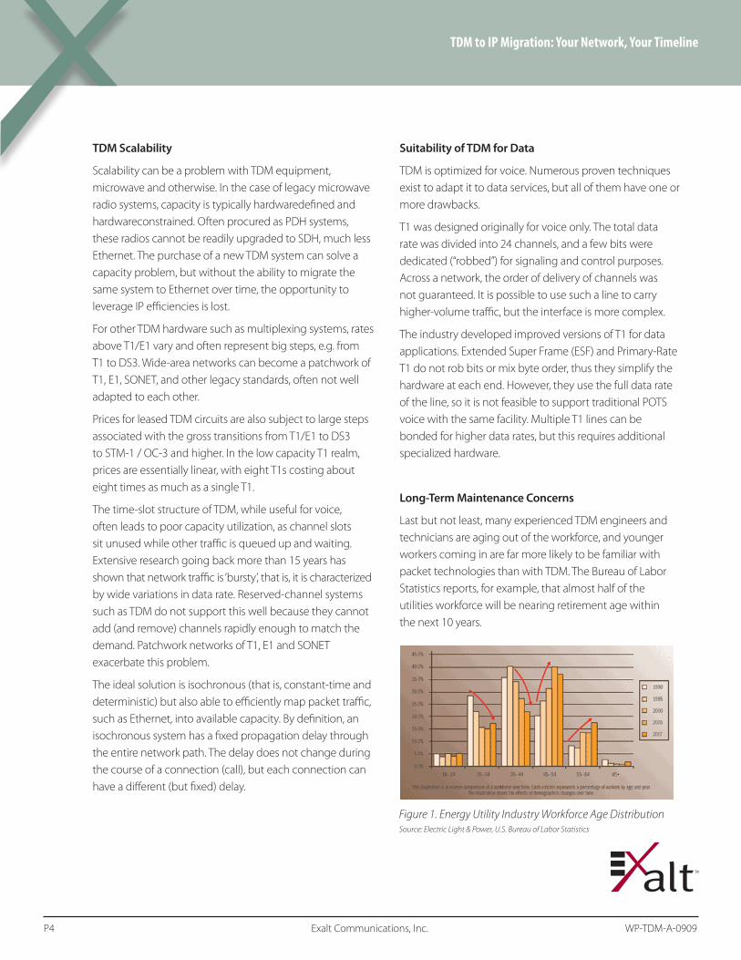
Lastbutnotleast,manyexperiencedTDMengineersandtechnicians are aging out of the workforce, and younger workers coming in are far more likely to be familiar with packettechnologiesthanwithTDM.TheBureauofLaborStatistics reports, for example, that almost half of the utilities workforce will be nearing retirement age within the next 10 years.
Figure 1. Energy Utility Industry Workforce Age DistributionSource: Electric Light & Power, U.S. Bureau of Labor Statistics
at the edge, Ethernet-compatible microwave backhaul and/or carrier-supplied leased Ethernet services when appropriate or available. For owned networks, the availability of leased Ethernet services presents a microwave backhaul redundancy alternative, as will be discussed.
The Internet Protocol Family
We have seen how Ethernet has become the dominant layer 2 protocol. At layer 3, the Internet Protocol (IP) , is almost as universal as Ethernet. It’s worth remembering that not all Ethernet traffic is IP, and IP can (and does) run across layer 2 links other than Ethernet . However, the two protocols are so dominant that people often use one when they really mean the other, or both.
IP and the related family of Internet protocols such as TCP and UDPprovidessophisticatedmechanismsforfaulttolerance,reliable delivery, prioritization and latency control. Together with Ethernet, IP forms a universal data transmission mechanism suitable for all applications.
As a result, a wide range of equipment vendors, a large combined product development budget, and a growing and well-trained workforce support Ethernet and the IP protocol family.
Ethernet – the Universal Solvent for Digital
Today one can make the assertion that any communications equipment that does not provide support for native Ethernet represents a dead end. Over the last 35 years, Ethernet has evolved to be the ‘universal solvent’ for data applications
Ethernet equipment easily interfaces to itself, usually with no manual configuration required. Systems which operate at different speeds and over different physical media share acommoninterface–theRJ-45port.Standardized Ethernet switches provide a universal interconnect and switching mechanism that requires little or no setup. Ethernet itself has been shown to be highly reliable; because it also supports spanning-tree protocols, it is easy to configure redundant paths. Even better, Ethernet has spawned a large industry dedicated to developing improved versions and driving down cost.
Increasingly, network service providers are installing and offering Ethernet-compatible connections for medium and long-haul applications, as well as local area service. This is a positive trend but even today, only about 13% of office buildings have access to fiber. Of course, this is one reason why microwave has become a popular medium for Ethernet transmission. With current microwave systems, it is feasible to build an Ethernet- centric network using standard Ethernet equipment
TDM to IP Migration: Your Network, Your Timeline
P5 Exalt Communications, Inc. WP-P25-A-0909
Layer # Layer Name
Key Responsibilities Data Type Handled
Scope
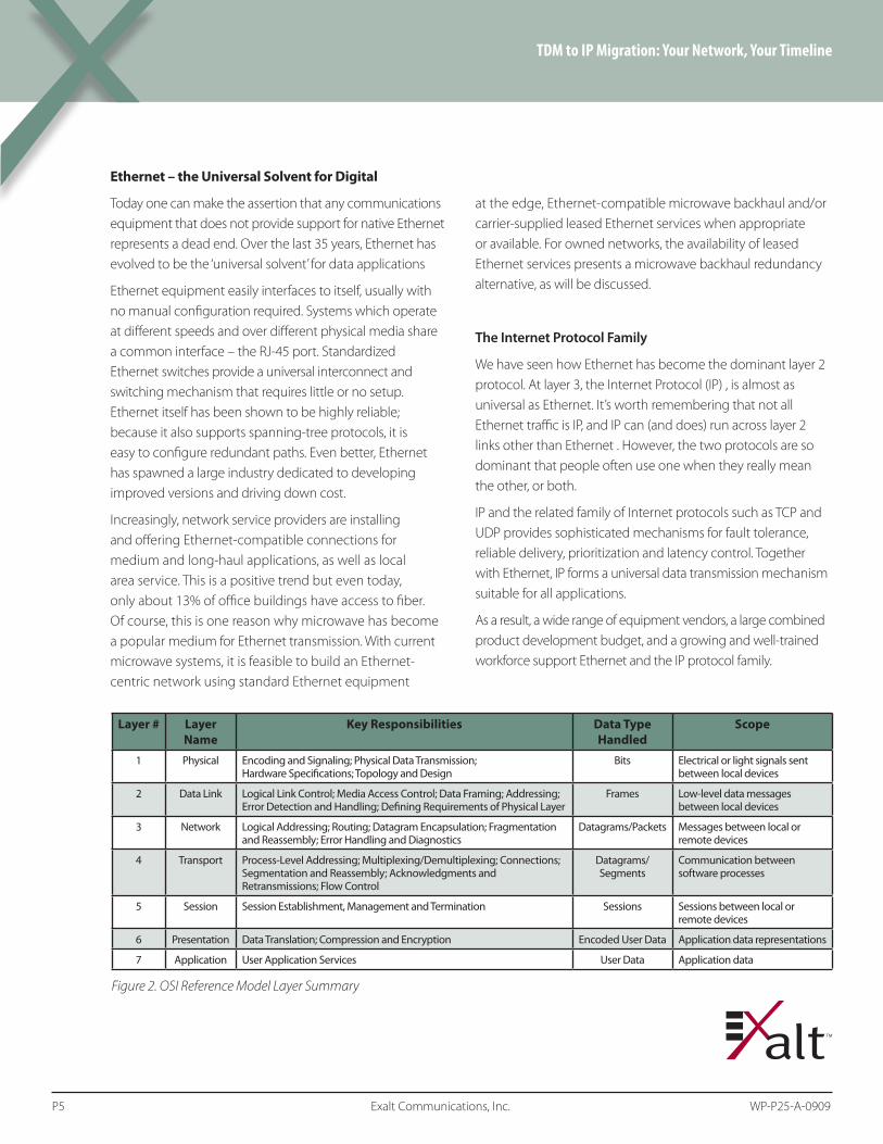
1 Physical Encoding and Signaling; Physical Data Transmission; Hardware Specifications; Topology and Design
Bits Electrical or light signals sent between local devices
2 Data Link Logical Link Control; Media Access Control; Data Framing; Addressing; Error Detection and Handling; Defining Requirements of Physical Layer
Frames Low-level data messages between local devices
3 Network Logical Addressing; Routing; Datagram Encapsulation; Fragmentation and Reassembly; Error Handling and Diagnostics
Datagrams/Packets Messages between local or remote devices
4 Transport Process-Level Addressing; Multiplexing/Demultiplexing; Connections; Segmentation and Reassembly; Acknowledgments and Retransmissions; Flow Control
Datagrams/ Segments
Communication between software processes
5 Session Session Establishment, Management and Termination Sessions Sessions between local or remote devices
6 Presentation Data Translation; Compression and Encryption Encoded User Data Application data representations
7 Application User Application Services User Data Application data
Figure 2. OSI Reference Model Layer Summary

TDM versus Ethernet
TDM architecture was built around the concept of isochronous data transmission. By definition, an isochronous system has a fixed propagation delay through the entire network path. The delay does not change during the course of a connection (call), but each connection can have a different (but fixed) delay.
TDM was originally designed to carry voice calls, and humans are sensitive to delay – especially to variations in delay – in conversation. TDM achieves its constant delay by reserving a dedicated portion of the network capacity for each connection. However, this capacity goes unused if there is no traffic.
Computer data networks, including Ethernet, do not offer a constant propagation delay. Most computer applications do not require it. As a result, Ethernet and other packet data networks make better use of available network resources.
While each approach has its adherents, the best real-world solution lies somewhere in the middle. Some traffic, such as voice, is delay sensitive, but other traffic is not. As a result, the industry has converged on an architecture that combines the best of both. By adding prioritization and timing mechanisms to Ethernet, it has been shown possible to create large, busy networks which carry voice, video and other time-critical traffic rapidly enough to meet real-world requirements, while at the same time making the best use of bandwidth by not reserving (and potentially wasting) network resources. A well-engineered TDM network can guarantee a maximum latency level, but in most applications a well-engineered Ethernet network can guarantee a fixed, if not quite as low, latency level.
ComputernetworksaddressQualityofService(QoS)atLayer2andLayer3.AtLayer2,twostandardsworktogethertoinsurefast packet delivery. Ethernet offers prioritized packet delivery via its 802.1p standard. This provides eight levels of priority, including one explicitly for voice or other time-critical traffic. AtLayer3,amechanismcalledMulti-ProtocolLabelSwitching,orMPLS,providesend-to-endnetworkprioritization.
These protocols form the basis for reliable, low-latency packet-based data transmission. The proof of their workability lies in the widespread adoption of Voice over IP (VoIP) for telephony and video conferencing. Vonage, Skype, Cisco and many other ven-dors and carriers offer telephony products that deliver excellent service over packet networks.
TDM to IP Migration: Your Network, Your Timeline
P6 Exalt Communications, Inc. WP-TDM-A-0909
Fixed Latency? In Ethernet?
Ethernet has never had a truly fixed network-delay, or latency time, but applications have been developed which simulate it. A VoIP application such as Skype time-stamps each packet on transmission. At the receiver, packets are deliberately delayed until the correct time. Thus, a packet which arrives early may be held for several milliseconds; a packet which is delayed in transmission will be held briefly if at all. Millions of trials have shown that it is quite feasible to simulate latencies under 100 milliseconds with this technique. One can argue that latency is not 100% guaranteed with this technique, but the traditional PDH/SDH hierarchy does not offer 100% guarantee either – frame slips and other events do happen.
Operational and Maintenance Cost Advantages of Ethernet
The sheer ubiquity of Ethernet has created a large ecosystem of equipment vendors and well-trained personnel. Collectively, this economy of scale has lowered the cost-per-bit dramatically. Ethernet and Internet together provide lower operational and maintenance costs, for several reasons. Most enterprises already have made substantial investments in equipment and personnel to supporttraditionalLANandInternetservices.Expandingthis incrementally to support wide-area deployments is easier and less expensive than creating and staffing a new TDM infrastructure.
In addition to microwave equipment, a complete TDM infrastructure typically has statistical multiplexers to combine low-data rate signals together to an aggregate of 56 or 64 Kbps. These digital streams are then fed into a channel bank and aggregated to a T1 rate, or higher. Numerous vendors make equipment suitable to these roles. Choice is nice, but each vendor’s equipment has its own user interface, method of operation, and limitations. Thus service personnel must be familiar with many kinds of equipment, and must understand the difference between robbed-bit and clear-channel systems, SF and ESF, and other variations.
Ethernet and IP systems are self-similar; from the edges of the network to the core, the same physical, electrical and logical standards are used. Service personnel have fewer interfaces and fewer technical concepts to master.
TDM to IP Migration: Your Network, Your Timeline
P7 Exalt Communications, Inc. WP-TDM-A-0909
Guaranteeing Latency
The Internet community has developed two key technologies in order to guarantee latency for delay-sensitivetraffic,suchasvoice.AtLayer2,theIEEE802.1pcommittee has defined a technique to assign priorities to Ethernet frames, and all modern Ethernet switches support it. This provides the fundamental mechanism for low-delay packet delivery.
AtLayer3,theMPLSstandardperformsasimilarfunctionfor IP packets. Together, they work well, and tests have shown that they will effectively throttle traffic when network performance requires it, either because too many users are on the network, or the network performance has been degraded due to hardware problems, such as a failed link.
The Ethernet standard defines a Bridge device. An Ethernet Bridge is any system which simply transfers Ethernet frames from point A to point B. It is not a switch; it is not a router. It is simply a point-to-point connection that accepts Ethernet frames at one end and reproduces them at the other. Ethernet Bridges typical transmit the frame over a fiber-optic or radio medium.
The key point about an Ethernet bridging is that it existsBELOWLayer2.Inshort,itisa‘dumb’device,asfar as layer 2 protocols are concerned. Thus, if a network implements802.1pQoSandMPLSatlayer3,the presence of an Ethernet Bridge will not affect the quality-of-service characteristics of the network. Any system which connects 802.1p QoS-aware Ethernet switches with Ethernet Bridge devices, such as radio links, will deliver QoS.
Ethernet Capacity Utilization Advantages
Packet-based technologies – i.e. Ethernet – inherently provide a multiplexing method that allocates bandwidth based on actual demand. When combined with a traffic prioritization system, it can often reduce overall bandwidth requirements in comparison to architectures which reserve dedicated circuits for different traffic classes. In most cases, an Ethernet network will make more efficient use of overall capacity; thus it may not be necessary to provision as much wide-area capacity as a TDM system would require.
The most-critical traffic is the traffic associated with alarms and control functions. This is not high-volume traffic, just high-priority. The Quality-of-Service (QoS) capabilities of Ethernet allow network designers to place critical alarm and control functions at the highest priority. This ensures that such traffic will be delivered promptly, even when overall network capacity has been degraded due to outage. Alarm and control traffic typically has an aggregate data rate in the thousands of BPS range; far less than Ethernet’s 10 Mbps. Thus there will always be sufficient capacity for alarm and control.
Systems which require voice circuits (such as public safety networks) can benefit from this as well. By placing voice traffic second in priority (only to alarm and control) basic voice connectivity is also assured, even in the presence of degraded network performance.
In both cases, network designers do not need to dedicate reserved bandwidth in order to ensure delivery of critical traffic. By implementing the prioritization features available with802.1p/qandMPLS,delay-sensitivetrafficcanusetheEthernet infrastructure with low latency, while still allowing traditional data traffic to share the same lines.
Ethernet offers a second capacity-utilization advantage as well. The ‘step sizes’ of data rate increases are more rational, and intermediate rates are supported. TDM step-sizes jump from 64 Kbps to 1.544 Mbps to 45 Mbps. Intermediate rates are possible, but require specialized hardware.
Ethernet moves smoothly from 10 to 100 to 1000 Mbps, with full- and half-duplex options, and in most cases data rates can be mixed without any special equipment. Most Ethernet gear auto-configures as well. Even better, Ethernet will move across non-standard-speed links, such as 802.11a/b/g/n, without any special rate-matching equipment. Thus, wired and wireless links can be combined easily.
TDM to IP Migration: Your Network, Your Timeline
P8 Exalt Communications, Inc. WP-TDM-A-0909
What is ‘toll quality’?
In the age of cell phones, Vonage and Skype, what is toll-quality? In short, it’s “better” phone service than you expect.
The term has historically reflected a combination of five factors: (1) a high probability of completing the call on the first attempt; (2) a low probability of dropping the call; (3) relatively low delay; (4) relatively low audio noise; (5) relatively good audio fidelity.
Cell phones changed the public’s perception of toll quality; perhaps more precisely, it changed the industry’s concept of what the public would accept in exchange for convenience or lower cost.
VoIP technology has taken things three steps farther, and in three directions, so to speak. Vendors such as Vonage offer POTS-like service to consumers, often using the same station instruments (i.e. phones) and dialing plans, but at lower cost than offered by the phone company. Vendors such as Cisco, Microsoft, Agere and others provide unified messaging to the workplace. Neither of these systems has sacrificed any aspect of toll quality.
Skype has become dominant in PC-to-PC voice and video. Skype outperforms POTS in at least two ways: it’s free, and it offers substantially better fidelity. Traditional POTS has an audio bandwidth of about 3 KHz and uses 12-bit-equivalent sampling at 8 KHz. Skype uses 16-bit sampling and offers 16 KHz and 24 KHz sampling rates giving audio bandwidths of 8 to 12 KHz. The market has demonstrated that ‘good’ and ‘free’ are popular, even if Skype’s call-placement reliability is not quite up to POTS standards.
Userswilldemandamaximumlevelofdelay,butthereisapoint of diminishing returns. Once that delay is kept below a certain threshold, convenience and cost become the drivers of voice telephony.
The benefits to antenna size and path length are further enhanced in the event that a network operator chooses to operate at a lower availability level (e.g. 99.9%) than typically used for TDM traffic. Furthermore, for the same total budget as a TDM solution, it is possible to deploy multiple radio and wired links in a redundant configuration.
Lower Cost Redundancy
Ethernet and IP together can provide multiple levels of fault-tolerance, and each protocol does so in a way that is integrated and easy to implement and support.
Ethernet is a best-effort protocol that supports retransmission. Thus, momentary link interruptions are handled and recovered quickly. Ethernet can be configured to automatically retransmit via an alternate route, using ‘spanning tree protocol’. This lets you deploy parallel paths, loops, or other redundant topologies without creating packet loops. No special switching or failover hardware is required. Furthermore, the full bandwidth of all links is available, unlike hot-spare systems, where one link sits at-the-ready, but idle.
Usingaspanningtreeanda‘meshed’topology(seesidebar),each node in a network has two (or more) connections to the mesh. This significantly increases overall reliability, but without the high cost of a full 1+1 redundancy model as is common in TDM systems.
Because Ethernet is agnostic about the physical layer, a network can be designed that combines traditional leased lineswithmicrowave,DSL,cellularandalmostanyothermedium to build the overall network.
IP routing offers another level of fault-tolerance. Industry- standard routers will always find the best available path to a destination; link failure merely causes a shift in routes. Again, because this is a standard feature of the protocol, implementation cost is low, and personnel are already familiar with its operation.
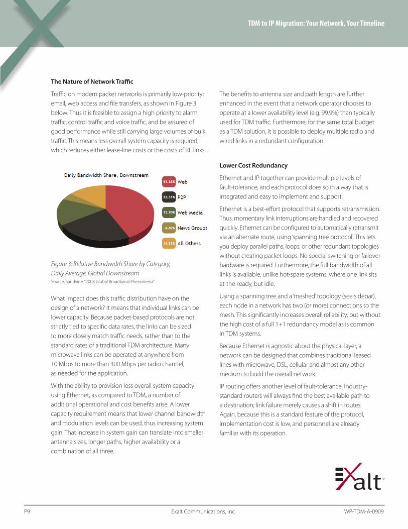
The Nature of Network Traffic
Traffic on modern packet networks is primarily low-priority: email, web access and file transfers, as shown in Figure 3 below. Thus it is feasible to assign a high priority to alarm traffic, control traffic and voice traffic, and be assured of good performance while still carrying large volumes of bulk traffic. This means less overall system capacity is required, whichreduceseitherlease-linecostsorthecostsofRFlinks.
What impact does this traffic distribution have on the design of a network? It means that individual links can be lower capacity. Because packet-based protocols are not strictly tied to specific data rates, the links can be sized to more closely match traffic needs, rather than to the standard rates of a traditional TDM architecture. Many microwave links can be operated at anywhere from 10 Mbps to more than 300 Mbps per radio channel, as needed for the application.
With the ability to provision less overall system capacity using Ethernet, as compared to TDM, a number of additional operational and cost benefits arise. A lower capacity requirement means that lower channel bandwidth and modulation levels can be used, thus increasing system gain. That increase in system gain can translate into smaller antenna sizes, longer paths, higher availability or a combination of all three.
TDM to IP Migration: Your Network, Your Timeline
P9 Exalt Communications, Inc. WP-TDM-A-0909
Figure 3: Relative Bandwidth Share by Category, Daily Average, Global DownstreamSource: Sandvine, “2008 Global Broadband Phenomena”
Another layer of fault-tolerance is available as an option – packet retransmission. While Ethernet and IP are both connectionless, best-effort protocols, the industry standard TCP protocol will retransmit as required to assure 100% reliable delivery for applications which require it. On the other hand, protocols which do not require it, such as voice, are not burdened by the cost or overhead of retransmission.
Together, these technologies have been shown to achieve 99.999% or better reliability of packet transmission. While individual packets are occasionally dropped, the overall delivery reliability of the network remains a ‘five nines’ or better.
Universal Application Support
In today’s computing world, there is nothing that cannot run over Ethernet/IP. Whether voice, alarms, video, remote data monitoring, telemetry or ‘traditional’ data applications, all are supported over IP. New services are migrating to IP as well – witness the trend in storage-area networks to carry low-level disk IO traffic over IP.
As a result, there is an ecosystem of companies investing billions of dollars in new and improved equipment and software. Enterprises which move aggressively to adopt an Ethernet/IP backbone take advantage of this, in the form of lower capital costs, lower operating costs, easier overall maintenance and access to an enormous array of compatible equipment.
For example, the first generation of Ethernet switches, deliveredintheearly1990s,werepricedatoverUS$100perport. Today, Ethernet switches operating at gigabit speeds costabout$25perport.
TDM to IP Migration: Your Network, Your Timeline
P10 Exalt Communications, Inc. WP-TDM-A-0909
Fault Tolerance in Microwave Networks
Traditionally, TDM architectures in microwave networks use a hot-standby technique to deal with line failures. A Monitored Hot Standby (MHS) line ‘protects’ one or more in-service links. This is called 1+1 protection. It works, but it substantially increases the cost per site without increasing the system capacity.
In contrast to MHS, diversity is used to ensure path availability in the event of deep path fading. In a TDM system, a deep fade incident that occurs in a non-diversity link can cause the TDM circuit to lose clock synchronization, in which case all data will be lost.
In a wired Ethernet network, a mesh or ring topology provides redundant paths. Thus the failure of any one line does not cut off traffic. Furthermore, as long as all lines are up,thefullcapacityisavailable.Lossofonelinereducescapacity but does not cut off the flow altogether. In many designs, the reduced capacity is not an issue, but in designs where it is critical, QoS can be used to insure that high-priority traffic gets delivered.
In the microwave scenario, it might appear that two Ethernet connections to a single site is no more cost- effective than MHS, but it still offers some advantages. First, data traffic is unpredictable and “bursty,” so the extra capacity is useful. Second, because redundant Ethernet connections are easily implemented with standard off-the-shelf hardware, beyond the additional radios themselves, the installation cost and the maintenance cost are low. Network maintenance personnel do not need training in 1+1 architectures or other standby solutions.
Although a deep-fade incident is a rare scenario, the implications of it on an Ethernet microwave system are likely to be less severe, due to the packet retransmission characteristics of Ethernet. In other words, Ethernet traffic can be reliably supported at a lower availability level than TDM traffic. Of course, it is up to the network operator to determine whether or not to take advantage of the ability to operate at lower availability levels.
Enterprise – Campus Scenario (Fortune 1000, Healthcare, Education)
Step 1. Begin by moving existing leased lines to microwave radio systems, using equipment which can carry native TDM as well as Ethernet. Add additional TDM microwave links as needed to connect to fiber connection points-of-presence.
Benefits: (a) Eliminates or minimizes ongoing operational costs associated with leasing.
(b) Establishes links with built-in flexibility to expand TDM and Ethernet capacity immediately, as needed.
Step2. Moveallinter-buildingLANtrafficfromTDMtoEthernet.Usethesamemicrowaveradio(s),butshift protocols.
Benefits: Moves traffic to more scalable protocol. Simplifiesnetwork-wideLANmanagement.
Step 3. Move all voice traffic to VoIP. Shift from legacy PBX to VoIP PBX; replace tie-lines with Ethernet.
Benefits: ReducesoperationalcostsbyeliminatingTDMequipment. Standardizes network on a network-wide management system. Organization gets full VoIP feature set, e.g. unified messaging.
How Can a Network Designer Migrate to IP Without Service Interruption?
Actually, it’s quite easy. Begin by deploying microwave radio equipment that carries TDM (as TDM, not packetized) and also can add Ethernet frames. This allows customers the ability to add Ethernet capacity instantly to existing legacy TDM microwave links without migrating their entire endpoint infrastructures to IP first.
When the radios are installed, TDM traffic is cut over to the TDM radio links, and old equipment may be taken out of service. If there is an immediate need for Ethernet as well, it can be added, and the equipment configured to provide the correct amount of capacity and priority for all traffic types.
At the same time, the Ethernet capability provides capacity for all IP data and emerging IP voice and video services. It also provides a migration path to growing IP-based services like VoIP and digital video. If, and when, network operators migrate all services to full IP infrastructures, connections can be gracefully migrated from TDM end-to-end circuits to Ethernet.
The relative ease of migration can be shown by two migration examples, one for enterprises operating in a campus-type environment; one for critical infrastructure enterprises.
TDM to IP Migration: Your Network, Your Timeline
P11 Exalt Communications, Inc. WP-TDM-A-0909

Using Network Topologies to Protect Ethernet
With packet-based systems, several network architecture alternatives are feasible:
• Daisy-chain,alsoknownastree.
• Ring
• Mesh
• Boundedmesh
The use of ring, mesh or bounded mesh topologies provides additional flexibility in the design of individual microwave links, as compared to links used in a daisy-chain topology. Specifically, the availability of redundant paths means that individual link availability requirements can be relaxed, allowing for longer paths, smaller antennas or both. Since network path redundancy still translates into more equipment, it often makes economic sense to balance this additional expense with such relaxed per-link availability requirements.
EthernetcanbeconfiguredtosupportRing,Mesh, and Bounded Mesh Topologies. As noted previously, no additional hardware is required; it is simply a configuration option on the Ethernet switch itself.
Enterprise – Critical Infrastructure Scenario (Utilities, Energy, Railroads)
Step 1. Overlay all at-capacity legacy TDM microwave links with dual-mode TDM/Ethernet equipment.
Benefits: Increases TDM capacity immediately and provides easy migration path to an all-IP infrastructure.
Step2. Upgradeanybelow-capacityTDMmicrowavelinkswith dual-mode TDM/Ethernet equipment.
Benefits: Ethernet capacity is in place to handle future migration to IP, but current TDM capacity is not impacted – it’s increased.
Step3. MoveallLANtrafficfromTDMtransportto Ethernet; especially microwave Ethernet. This can be done on the same radio, simply by shifting from TDM ports to Ethernet ports.
Benefits: MovesLANtraffictoamorescalableprotocol.Simplifies network-wide management. Enables QoSandVLANacrosstheentirenetwork.Reducesover-provisioned capacity by moving to a shared resource.
Step 4. Move all voice traffic to VoIP, by shifting from PBX toIPPBX.ReplaceTDMtrunksandtie-lineswithEthernet. Implement on microwave.
Benefits: Organization can take advantage of VoIP feature set,e.g.unifiedmessaging.ReduceOPEXcosts by eliminating TDM equipment. Further reduce maximum provisioned capacity by moving to a shared resource – relax link design requirements.
Step 5. Move real-time traffic to IP. Prioritize traffic capacity (using QoS) and move mission critical traffic to it. Once all legacy TDM traffic has been migrated, decommission legacy TDM-only equipment.
Benefits: Real-timeapplicationperformanceisensuredwith QoS. All traffic and systems can now be monitored using standard management protocols.Retiredequipmentcanbesold.
TDM to IP Migration: Your Network, Your Timeline
P12 Exalt Communications, Inc. WP-TDM-A-0909

Network Topology Examples
Daisy-Chain
The daisy-chain or string topology is common in circuit-switched networks and thus is often a default configuration for packet-based networks that evolve from circuit-switched networks. In this topology, there is no path redundancy, so additional equipment must be used at each site to increase path availability. Even with equipment redundancy, each node is still subject to outage under catastrophic failure conditions.
Ring
Ringtopologyisaspecialcaseofastringtopologyinwhichthe beginning and end nodes are one and the same. In a ring, every node has exactly two connections, each to itsimmediateneighborinthering.Ringtopologiesarecommon in TDM systems, especially fiber-optic ones, but present two challenges:
If one link on the ring becomes congested, the entire ring may be affected.
Largeringstypicallyhavealargenumberofhops,whichmay increase latency in some cases.
Ringsmustincorporateextraequipment,layersand/or capacity to safeguard against congestion or node failure, and this approach carries with it an obvious additional expense.
TDM to IP Migration: Your Network, Your Timeline
P13 Exalt Communications, Inc. WP-TDM-A-0909
Figure 4: Daisy-chain topology
Figure 5: Ring topology
Mesh Topology
A mesh is any network where most, if not all, nodes on the network have at least two connections to other nodes. In some cases, every node has a connection to every other node. This is called ‘fully meshed’. Networks which are not fully meshed are known as Bounded Meshes.
For reliability, it isn’t necessary to have a fully meshed network; it is only necessary that each node have two or more connections to other nodes. For reasons of cost, fully meshed networks are rarely deployed in practice.
Bounded Mesh
A bounded or constrained mesh network is a mesh network in which some degree of redundancy has been compromised in favor of affordability. A bounded mesh network thus represents a practical trade-off between protection and cost; for this reason, it is one of the most common packet network topologies.
The bounded mesh network has the additional advantage of being able to grow organically over time, rather than requiring a defined network design from the outset. In fact, bounded mesh networks often grow from existing ring networks when a pair of nodes on opposite sides of the ring is connected. Additional nodes can be brought into the mesh with the choice of the number of redundant paths dependent upon the relative importance of that node in the network. Similarly, existing nodes that are not connected can be connected at some point in the future in order to add redundancy and/or capacity to the network.
Figure 6: Mesh Topology – Fully Meshed
Figure 7: Bounded mesh topology

IP Functionality
VLAN tagging. Support for 802.1q is a prerequisite for extendingVLANassignmentsacrossageographically distributed enterprise that is connected by microwave links.
QoS. In order to accommodate the full range of traffic types and apply robust traffic classification, systems should allow quality of service to be established on the basis of multiple metrics. At minimum, QoS should be able to be applied onthebasisof802.1pbits,VLANIDandsourceordestinationMAC address. The ability to support up to eight priority levels and eight queues will ensure maximum flexibility in assigning priorities.
Rate limiting. Ethernet rate limiting is a valuable tool for ensuring that a given user group or application does not consume too much of the available capacity.
Layer 2 switching. TheavailabilityofLayer2switchingintheradio both reduces cost and simplifies deployment when compared to the alternative of using an external switch.
Interfaces
Gigabit Ethernet. In order to accommodate future capacity scenarios, the system should support multiple GbE ports, including10/100/1000BaseTcopperports(RJ-45)andfiber-optic interfaces for longer distance applications and greater resistance to interference. To simplify deployment and reconfiguration, all interfaces should be software-configurable.
PDH. For any enterprise migrating from TDM to IP, a new system must support the T1, E1 and DS3 requirements of the current network as well as the Ethernet requirements of the future network. In order to minimize sparing and inventory requirements, the fewer models required to support the range of PDH requirements in the network, the better. As with Ethernet ports, TDM ports should be able to be configured remotely via software to minimize the expense of site visits.
Requirements for Ethernet Microwave Links
While there will always be a role for wired connections in anEthernetsystem,privatewirelessLANandWAN-like connections are becoming increasingly common in campus enterprise environments not only for applications where a wired connection is difficult to implement, but simply as a cost-effective, reliable alternative to leased lines. Of course, in critical infrastructure environments, microwave Ethernet links are a natural evolution from widely used TDM-based microwave backhaul.
In either environment, an Ethernet-capable microwave system must meet certain requirements in order to fully leverage the cost and reliability advantages inherent to Ethernet operation. Additional capabilities will further reduce deployment costs and enhance deployment flexibility.
Ethernet System Performance
Latency. Latencyandjittermustbelow,ontheorderof 100 µsec or lower; latency should not be affected by the packet rate. Many IP applications, notably VoIP, use short packets; it is important to be able to process packets at wire speed in order to ensure quality of service for latency-sensitive applications, as well as meet the overall data rate.
Latencytakesonaddedimportanceinthecontextof multi-hop networks, as is common-place in long-haul backbone deployments. Delay budgets may be as small as 1 to 2 ms; the number of hops in a daisy-chain topology can easily number in excess of five or even ten.
Loss-of-link detection. There should be robust loss-of-link detection and reporting.
Packet size. The system should support frame aggregation on higher-speed links, typically above 100 Mbps. This increases overall throughput.
TDM to IP Migration: Your Network, Your Timeline
P14 Exalt Communications, Inc. WP-TDM-A-0909

Security
Data payload encryption. Because it is a radio system and inherently subject to eavesdropping, the system must support strong encryption, to the National Institute of Standards (NIST) FIPS 197 standard or better. Typically, this means 256-bit AES encryption.
Management traffic encryption. As with the data traffic, management must also be secure, using SNMPv3. The management interface must also be easy to use as well as secure.
Scalability & ‘Evolvability’
Defined latency. The system must use an over-the-air technology that is inherently isochronous, so that TDM support is truly low-jitter.
Adaptable scaling. The system must easily, yet correctly, support TDM and Ethernet traffic. This makes the system evolvable – that is, it can drop into existing TDM networks, and support service migration on a timeline set by the network architects and engineers. There need be no rush, no ‘forklift upgrade’.
At the same time, the system should be scalable, so that capacity can be increased in reasonable increments as required, without performing a ‘forklift upgrade’. Scalability also applies to legacy TDM traffic; an ideal system is able to carry existing TDM traffic while supporting new services on the Ethernet side, such that traffic can be migrated gradually, until there is no more need for TDM support.
Management
Configuration and management options must be flexible, so that the microwave system can talk to both legacy TDM EMS and newer network-centric NMS systems.
SDH. The migration of high capacity backbone networks will often entail a move from SDH to Ethernet, thus the system must support multi-DS3, OC-3 or STM-1 interfaces in addition to GbE. The same configurability requirements mentioned above apply.
RF System Performance
High modulation rates. Whatever the business, future throughput requirements will arise. Systems that offer 256QAM modulation will be able to wring the most capacity out of a given channel bandwidth. This is especially important for situations in which the selection of available channel bandwidths is limited.
Adaptive modulation. In licensed band systems, adaptive modulation capabilities are a desirable option, enabling the system to deliver high data rates, yet scale down gracefully under adverse conditions. In a network that utilizes network path diversity, the availability of adaptive modulation allows designers significant flexibility in path design, enabling lower but acceptable availability levels, longer paths, smaller antennas or any combination of the three. Prioritization mechanisms must accommodate such adaptive modulation and ensure the delivery of the highest priority traffic.
System gain – throughput tradeoff. Maximum peak throughput is not the driving factor for every link. In many cases, it would be desirable to trade off maximum throughput for additional system gain in order to achieve higher link availability or enable the use of smaller antennas. Thus, a mechanism such as trellis code modulation that enables this trade-off is a useful option.
TDM to IP Migration: Your Network, Your Timeline
P15 Exalt Communications, Inc. WP-TDM-A-0909
About Exalt
Exalt Communications designs, manufactures and markets next generation licensed and license-exempt microwave systems for enterprises, government organizations and service providers worldwide. Exalt products are designed to solve the network bottlenecks associated with the growing demand for IP- based voice, data and video applications and the resulting migration from TDM to IP-based networks. With a flexible architecture and universal product platform, Exalt provides a full range of carrier-class microwave radio systems that meet the demand for a cost-effective and flexible alternative to fiber and leased lines.
The company’s product portfolio includes a wide range of both licensed and license-exempt radios covering all popular frequency bands ranging from 2 - 40 GHz, capacities ranging from 20 Mbps to 1 Gbps and multiple configurations including all-indoor, all-outdoor and split-mount (indoor/outdoor). Exalt systems deliver:
• Carrier-classavailability,performanceandfeatures
• NativeEthernet,nativeTDMoranycombinationofthetwo to support TDM to IP migration
• Ahighdegreeofflexibility,madepossiblebydiverseconfiguration options and full software configurability
• Arichsetofdatanetworkingfeatures
• Thehighestlevelofdataandmanagementsecurity
Conclusion
Packet-based networks are here to stay and traffic of all types is moving over them. The trend toward unified packet-based data communications is equally clear.
While an organization may have no immediate requirement to move all of its TDM-based services to IP, it is clear that such a move is technically feasible. Moreover, packet-based systems can deliver the low latency and high availability that even the most mission critical alarm and control systems demand.
Whether the need to transition to IP is immediate or a few years out, organizations should begin planning and implementing this transition today by installing microwave and other equipment that is IP-ready while still handling legacy (and native) TDM. Fortunately, network planners can deploy a single radio platform that supports both and allows full migration to packet technology when the time is right.
The economic arguments for migration to IP are just as compelling as the technical ones. From system scalability to equipment cost to maintenance to simplified management, IP-based systems deliver better value than their TDM-based counterparts.
So for organizations of all types, the question is clearly not whether but how quickly to begin migrating to the all-IP network. The good news is that whatever migration path and timeline private network operators choose to follow, there is microwave radio equipment designed to support a smooth, trouble-free transition from TDM to IP.
TDM to IP Migration: Your Network, Your Timeline
P16 Exalt Communications, Inc. WP-TDM-A-0909

ExtendAir™
ExtendAir™ is a complete line of entry-level licensed and license-exempt point-to-point microwave radios systems that, for the first time, brings high-end performance, range andfeatures–includingnativeTDM–tothesub-$5,000per-link category. ExtendAir is the first entry-level microwave radio system to offer advanced features such as built-in Layer2switching,3-portEthernet,full-speed256-bit AES encryption, Ethernet rate limiting and SNMPv3 management. ExtendAir native TDM capability is a first for license-exempt systems. All ExtendAir radios support multi-levelQoSandVLANtaggingforcompletetraffic management flexibility.
For more information about Exalt, visit www.exaltcom.com.
EX-i Series (All-indoor)
The EX-i Series of all-indoor radio systems includes licensed and license-exempt systems offering flexible, upgradeable native Ethernet and native TDM for low, medium and high capacity applications with support for up to 16xT1, 1xDS3 and up to 250 Mbps full-duplex Ethernet throughput and available Gigabit Ethernet.
EX-r Series (All-outdoor)
The EX-r Series of all-outdoor radio systems includes licensed and license-exempt systems offering flexible native Ethernet and native TDM transport for low, medium and high capacity applications, delivering up to 440 Mbps sustained aggregate user throughput and available Gigabit Ethernet.
EX-s Series (Split-mount)
The EX-s Series split-mount radios are frequency-division duplexing (FDD) systems operating in ANSI/FCC and ITU/ETSIlicensedfrequencybandsfrom6to40GHz. EX-s series radios are fully software configurable and, with native Ethernet and native TDM, designed to support any TDM to IP migration plan. Available interfaces include 4-16xT1/E1, 1-4xDS3, 2xOC3 and 2xSTM-1, with per carrier Ethernet capacity up to 366 Mbps full-duplex and available Gigabit Ethernet.
TDM to IP Migration: Your Network, Your Timeline
P17 Exalt Communications, Inc. WP-TDM-A-0909
Jitter The variation in latency. Very small amounts of jitter, on the order of50ppm,usuallyhavenoeffectonasystem.Largeramountsofjitter (or latency variation) must be compensated for, especially in voice applications
Microwave Exact definitions vary, but generally microwave refers to radio systems operating at a frequency of 1 GHz or above.
Modulation, QAM Modulation refers to the method by which an electrical or radio signal is varied, or modified, in order to represent the information being transmitted. Simple systems include the AM and FM used by consumer radios. Modern digital system often use Quadrature Amplitude Modulation, a technique where multiple signals are created exactly one-quarter cycle out of phase (hence the term quadrature) and then varied in amplitude to represent information. Because multiple signals are being used, lots of information can be transmitted in parallel. The number of signals is indicated by a number, e.g. 16QAM or 64QAM. These refer to 16 and 64 bits-at-a-time systems.
1+1 protection A technique for providing a backup for a communications circuit by having a second identical circuit operating in parallel.
MHS (Microwave Hot Standby) Similar to 1+1 protection, as applied to radio.
SCADA(SupervisoryControl&DataAcquisition) It refers to an industrial control system that monitors, and may control, an industrial process. It is commonly used along pipelines and other physically-large infrastructure to monitor performance. To the extent it is used for control, rapid response
time becomes critical.
Glossary
General Terms
Asynchronous A term used for data transmission when there is NOT a strict relationship between the timing of the send and the timing of the receiver. The receiver is expected to figure out how exactly how fast the sender is sending. Old-fashioned dial-up modems used asynchronous transmission.
Synchronous A data transmission where the receiver is able to receive or otherwise ‘recover’ the exact timing clock used by the sender. Although more complex to build, it is capable of higher speeds.
Isochronous A special case of synchronous where not only the clock is recovered, but the exact delay in transmission is determined and held constant. This is a requirement for voice traffic. All isochronous circuits are synchronous, but not all synchronous circuits are isochronous.
Circuit Specifically, a complete electrical path; but used idiomatically to refer to almost any type of communications channel or connection.
Latency Looselyspeaking,transmissiontime.Moreprecisely,thetimeittakes for a given bit in a message to travel from the transmitter to the receiver. While most electrical signals (and radio) travels near the speed of light, the travel time is not zero, and can be significant. In two-way voice communications, humans begin to notice the delay when it exceeds about 100 milliseconds, and will find the delay very annoying when it exceeds 500 milliseconds.
Note that latency is not the same thing as transmission rate. It is possible to have a transmission link with a capacity of hundreds of megabits per second, but high latency. Likewise, a slow link can be low latency.
TDM to IP Migration: Your Network, Your Timeline
P18 Exalt Communications, Inc. WP-TDM-A-0909

Primary Rate To further improve service, ESF was enhanced to created PrimaryRate.
Digital Hierarchy Over the years, several systems have evolved to permit the combination of multiple digital streams into single, faster digital streams. Collectively, such systems are called Digital Hierarchy.
PDH (Plesiochronous DH) The system originally developed by the phone company, consisting of T1, T1C, T3, and other standards.
SDH (Synchronous DH) Also known as SONET, this system was developed specifically to take advantage of fiber-optic technologies.
SONET (Synchronous Optical Network) See above. The SONET hierarchy is OC-1, OC-3, OC-12, etc, where each number refers to the number of multiplexed 51.84 Mbps signals. This, OC-40 is approximately 2.4 Gbps.
DSL (Digital Subscriber Loop) When the phone company was finally compelled to offer digital servicedirectlytoconsumersatreasonableprices,DSLtechnologywas used to transmit digital data, at 1 to 3 Mbps, over the same wiring used for POTS service.
ILEC (Incumbent Local Exchange Carrier) Term used for the legacy local phone company after the AT&Tbreakup.
CLEC (Competitive Local Exchange Carrier) Term used for the other companies which are supposed to offer phone service.
PBX (Private Branch Exchange) A small telephone switch that supports all of the phone extensions with an organization.
EMS/NMS (Element/Network Management System) EMS systems were developed by the phone company to monitor and managed telephone transmission equipment. Network Management Systems were developed by the computer industry
to manage networks. The two systems are slowly converging.
Telephony Terms
Many of the terms originating in the telephony industry are inter-related to other terms. Thus, this glossary presents them in a logical, rather than alphabetical, order
Acronym Meaning Definition
POTS (Plain Old Telephone Service) POTS is a retronym coined after the developed of more advanced digital phone systems to refer to the traditional analog telephone and service. POTS was the only type of phone service until the 1970s.
PCM (Pulse Code Modulation) A technique for converting analog signals to digital ones, used to convertPOTScallstodigital.IntheUS,PCMisa64,000bpsdigitaldata stream.
TDM (Time Division Multiplexing) A technique for combining (multiplexing) several signals onto the same transmission facility. In a TDM system, each signal takes turn using the transmission facility, in a round-robin fashion. Careful synchronization assures the signals can be unscrambled at the receive end.
Channel Bank A device that combines multiple individual channels (typically voice circuits) into a single higher-speed transmission facility. Inotherwords,atypeofmultiplexer.IntheUS,achannelbankcombines 24 64Kbps circuits into one T-1 circuit. In Europe, 30 channels are combined to make an E-1 circuit.
T1, E1 High-speed digital transmission systems originally developed to carry telephone calls over longer distances without degradation. A T1 lines operates at 1.544 Mbps, an E1 line operates at 2.048 Mbps.
CSU/DSU Channel (Data) Service Unit The two components that act as the interface between the digital signal and the actual physical transmission facility, e.g., the wire.
ESF (Extended Super Frame) With the growing desire to send computer data instead of voice over long-distance telephone wires, the telephone industry developed an improved T1 called ESF.
TDM to IP Migration: Your Network, Your Timeline
P19 Exalt Communications, Inc. WP-TDM-A-0909

RJ-45 Part of a family of low-cost but reliable connectors developed by the phone company for telephone wires. It has become the de-facto standard for modern Ethernet systems based on cat-5 wiring.
CAT-5 (Category 5) Originally used by Belden Wire referred to a particular grade of light-gauge, 8-conductor cable intended for data communications. It has since become the common term for Ethernet cable. Cat-5 wires are terminated with RJ-45plugs.
QoS (Quality of Service) In networking, it refers to the ability of a network to guarantee a maximum transmission time, even when busy.
802.1p A specific standard for defining QoS.
MPLS (Multi-Protocol Label Switching) A protocol within the IP family designed to insure QoS in a large network.
VoIP (Voice over IP) The use of packet networks – specifically Ethernet and IP – to carry telephone calls. Among the best-known examples are Vonage and Skype.
VLAN / 802.1q (Virtual LAN) VLANsarelogically-isolatedsectionsofanetwork,usedto manage traffic flows and provide enhanced security. 802.1qisaspecifictechniqueformanagingVLANs over Ethernet.
Networking Terms
Ethernet Formally known as 802.11, it is the basis of all modern computer communications. Its key feature is that it is completely decentralized; there is no primary controller. Ethernet sends data in packets (called frames) of varying sizes, and uses a probabilistic method, based on random numbers, to determine who gets to talk and when. This technique is called CSMA/CD.
802.11a/b/g/n A family of standards for transmitting Ethernet traffic over radio.
IP (Internet Protocol) The foundation layer of the Internet. IP provides a global system for naming endpoints and routing traffic between them. Hence it is often called a routing layer. In the IP system, every endpoint has an IP address, a 32-bit number conventionally written as four decimal values (1 to 255) separated by dots; for example, 204.50.56.113.
LAN (Local Area Network) A term used for a collection of computers connected over a ‘short’ distance. Short is usually defined as any distance short enough that the cost of the data communication facility is not significant compared to other costs in the system.
WAN (Wide-Area Network) A term used for a collection of computers connected over a distance long enough that the cost of the data communication facility is significant compared to other costs in the system.
SAN (Storage-Area-Network) Applications of networking technology directly to storage media; that is, disks. The goal is to make the storage appear seamlessly available regardless of physical location.
TDM to IP Migration: Your Network, Your Timeline
P20 Exalt Communications, Inc. WP-TDM-A-0909

Exalt Communications, Inc.
580 Division Street
Campbell, CA 95008
ProducedintheUnitedStatesofAmerica.
©2009 Exalt Communications, Inc.
All rights reserved.
More details on Exalt point-to-point microwave radio systems may be found at:
www.exaltcom.com
Exalt and the Exalt logo are trademarks of Exalt Communications, Inc. Other company and product names may be trademarks of others. Information contained in this document may be subject to change without notice.
TDM to IP Migration: Your Network, Your Timeline
P21 Exalt Communications, Inc. WP-TDM-A-0909