tea co2-laser treatment of coated and corroded … co2-laser treatment of coated and corroded metals...
TRANSCRIPT

Loughborough UniversityInstitutional Repository
TEA CO2-laser treatment ofcoated and corroded metals
This item was submitted to Loughborough University's Institutional Repositoryby the/an author.
Additional Information:
• A Doctoral Thesis. Submitted in partial fulfilment of the requirementsfor the award of Doctor of Philosophy at Loughborough University.
Metadata Record: https://dspace.lboro.ac.uk/2134/27042
Publisher: c© C.A. Cottam
Rights: This work is made available according to the conditions of the CreativeCommons Attribution-NonCommercial-NoDerivatives 2.5 Generic (CC BY-NC-ND 2.5) licence. Full details of this licence are available at: http://creativecommons.org/licenses/by-nc-nd/2.5/
Please cite the published version.

This item was submitted to Loughborough University as a PhD thesis by the author and is made available in the Institutional Repository
(https://dspace.lboro.ac.uk/) under the following Creative Commons Licence conditions.
For the full text of this licence, please go to: http://creativecommons.org/licenses/by-nc-nd/2.5/

,
PilkingtonLibrary
.~ Loughborough • University
AuthorlFiling Title ......... ~!~ ~ ................... . ............ , ..................................................... .. Vol. No. ............ Class Mark ....... :1 ............... .
Please note that fmes are charged on ALL overdue items.
''',


TEA COrLaser Treatment of Coated and
Corroded Metals
by
Christopher Andrew Cottam
A Doctoral Thesis
Submitted in partial fulfilment of the requirements for the award of Doctor of Philosophy at Loughborough University
. August 1998
"' -,
© by C. A. Cottam 1998
~ '.'.
- • ~ ,11 Ln~t'orough . ., Ulln!(':'>iry'
P" ~f·:-txy ;.' - .' ,,,,.:;.....
Datr. ~q~"' .... I- '.
C1w ... , .... ~ ........... , ...•.
Ace u-tO 2..0<6Wtt No. 'V':_' •• : .......... _
,'- -"-.. ',-

Acknowledgements
I would like to thank all the people at Loughborough University physics department
who have provided a warm and friendly environment in which to complete my
studies.
Special thanks go to the members, past and present, of the optoelectronics department,
who added colour to even the greyist of days.
Special thanks also go to my supervisor, David Emmony, for providing me with the
opportunity to enter a unique and interesting field of research.
I would also like to acknowledge the contribution made by the National Museums and
Galleries on Merseyside in sponsoring and supporting the project.
The contributions of Gary Critchlow and Ana Cuesta merit special attention and it has
been a great pleasure to collaborate with two such gifted scientists.
Finally, I would like to acknowledge the support provided by the technicians without
which this project would not have been possible. In particular, John Oakley has been
essential to this project and never failed to meet an unreasonable deadline!

Abstract
A selection of corroded, painted and lacquered metals have been subjected to high
powered, pulsed TEA C02-laser radiation to investigate self-limiting cleaning and
treatment processes. Changes in the surface chemistry were observed and recorded
using a variety of surface analysis techniques including X-ray Powder Diffraction,
Auger Electron Spectroscopy and X-ray Photoelectron Spectroscopy. Changes in
surface appearance were recorded using colour macro-photography and Scanning
Electron Microscopy. The effects of both plasma and sub-plasma laser fluences were
investigated.
Results from naturally and artificially corroded metals show that the ability of the
laser to remove or modify corrosion products depends upon their precise composition.
All paints and lacquers tested were susceptible to ablation at sub-plasma fluences.
Aged paints, resilient to removal by volatile solvents, could also be removed by the
laser. Modification of metal surfaces at plasma fluences produced a significant
increase in the bond durability of adhered metal coupons.
The potential for the laser to be used in the fields of sculpture conservation, industrial
paint removal, and metal adhesion pretreatments are discussed and conclusions
presented.

TEA COr Laser Treatment of Coated and Corroded Metals
Contents
Introduction
Chapter 1: Corrosion and Conservation of Metals
Introduction
1.1
1.2
1.3
General Metallurgy
1.1.1 Atomic structures of metals
1.1.2 Micro-structures of metals
1.1.3 Alloy structures
1.1,4 Corroded micro-structures
1.1.5 Optical properties of metals
Metals in Sculpture, Historical Artifacts and Modern Industry
1.2.1 Introduction
1.2.2 Cast metals
1.2.3 Worked metals
1.2,4 Present day metals and alloys
Corrosion and Patination
1.3.1 The corrosion process
1.3.2 Factors affecting metal corrosion
1.3.3 Species of corrosion product
1.3,4 The value of corrosion
1
2
3
5
9
10
14
14
14
19
20
22
23
26
30
39
1.4
1.5
Organic Coatings
1.4.1 Constituents of organic coatings
1.4.2 Types of organic coatings
1.4.3 Methods of protection
1.4.4 Deterioration of coatings
1.4.5 Removal of organic coatings
1.4.6 Accelerated ageing techniques
Metal Conservation
1.5.1 Large, outdoor sculpture
1.5.2 Small, metal artefacts
1.5.3 Patina stabilisation
1.5.4 Re-patination
Summary
References
Chapter 2: C02"Laser Cleaning Methodology and Monitoring
2.1 Laser Cleaning
2.1.l Principles of TEA CO2-lasers
2.1.2 Laser interaction with materials
2.1.3 Factors affecting ablation characteristics
2.1.4 Plasma/sub-plasma cleaning effects
2.1.4.1 Temporal beam profile (TBP) measurements
2.1.5 Beam delivery
2.1.6 The CO2-laser cleaning system
43
43
44
46
46
48
49
49
50
51
53
54
55
56
60
61
62
64
68
70
72
74
2.2
2.3
2.4
Surface Chemistry Analysis
2.2.1 X-ray powder diffraction analysis (XRD)
2.2.2 X-ray photoelectron spectroscopy (XPS)
2.2.3 Auger electron spectroscopy (AES)
2.2.4 Contact angles
Surface Topographical Analysis
2.3.1 Colour photography
2.3.2 Embedded cross-section
2.3.3 Scanning electron microscopy (SEM)
In-line Laser Observations
2.4.1 Surface temperature measurement
2.4.1.1 Bulk temperature measurement during ablation
2.4.2 In-line laser induced breakdown spectroscopy (LIDS)
2.4.3 Acoustic monitoring
Summary
References
Colour Photographs
"
75
75
80
81
83
85
85
85
87
87
87
90
95
97
100
101
103
Chapter 3: Sub-plasma Laser Cleaning and Treatment
3.1 Artificially patinated samples 104
3.1.1 Experimental 105
3.1.2 Case la 108
3.1.3 Case 2a 109
3.1.4 Case 3a III
3.1.5 Case 4a 113
3.1.6 Case Sa 114
3.1.7 Case 6a 115
3.1.8 Case 7a 117
3.1.9 Case 8a 119
3.1.10 Case 9a 122
3.2 Naturally Patinated Samples 124
3.2.1 Case In 124
3.2.2 Case 2n 128
3.2.3 Case 3n 130
3.2.4 Case 4n 134
3.2.5 Case 5n 137
3.2.6 Case 6n 138
3.2.7 Case 7n 139
3.2.8 Case 8n 141
3.2.9 Summary of results 142
3.3 Organic Coatings 148
3.3.1 Fresh paint 148
3.3.2 Fresh lacquers 150
3.3.3 Aged and weathered coatings 151

3.3.4 Residual layers
References
Colour Photographs
Chapter 4: Plasma Laser Cleaning and Treatment
4.1
4.2
Plasma effects
4.1.1 Plasma cleaning mechanisms
4.1.2 Initiating and sustaining plasma
4.1.3 Plasma observations
4.1.4 Plasma cleaning
Cleaning and adhesion
4.2.1 Aluminium
4.2.2 Steel
4.2.3 Hot-dip Galvanised (HDG) mild steel
4.2.4 Summary of results
References
SEM Micrographs
158
161
163
175
175
176
179
180
184
186
192
197
202
204
206
Chapter 5: Conclusions and Further Work
5.1 Conclusions
5.1.1 Metals without a coating
5.1.2 Metals with inorganic coatings
5. 1.3 Metals with organic coatings
5.2 Further Work
5.3 Laser Safety
References
Appendices
209
209
211
216
217
219
221
222

Introduction
The ability of high-powered laser radiation to alter solid surfaces has been known
since the first high-powered lasers were produced. This property has been exploited in
many areas of surface cleaning and surface treatment. This thesis explores two areas
of TEA C02-laser treatment that have thus far received little attention:
• The laser cleaning and treatment of coated and corroded metals at sub-plasma
fluences, eg for the cleaning of metal sculpture.
• The laser cleaning and treatment of metals at plasma-fluences, e.g. for adhesive
pretreatments.
The use of lasers in the cleaning of sculpture and objects of historical and cultural
interest has grown in popularity over recent years. When conditions are favourable,
the laser may remove dirt and detritus from a target without damaging or altering the
underlying material, thus offering a worthwhile improvement on conventional
cleaning techniques. Whilst lasers have gained acceptance in the cleaning and
treatment of materials such as stone and paper, there remains much work to be done in
the area of metals. This thesis looks at the potential of TEA C02-lasers to clean and
treat corroded and coated metals, and assesses the value of the laser as a conservation
tool.
The growing concerns, over recent years as to the environmental impact of volatile
solvents has provided industry with a strong impetus to develop environmentally
friendly methods of cleaning metal surfaces. A field where surface cleanliness is of
considerable importance is in metal adhesion where large amounts of volatile solvents
are required to degrease the surface of the metal adherends. This thesis shows that
using the TEA C02-laser at plasma fluences offers an effective and environmentally
friendly alternative to volatile solvents to clean the surface of metal adherends.
In writing-up this thesis, it was considered to be most effective to keep the results as a
collection of case studies and present them in Chapters Three and Four, for targets
treated below and above the plasma fluence respectively. This left Chapters One and
Two for an introduction and overview of the methodology employed, and Chapter
Five for conclusions and further work. Additional details are given below:
Chapter One: 'Corrosion and Conservation of Metals' provides a detailed introduction
to metallurgy and both organic and inorganic coatings that exist on old and new.
metals. A review of existing conservation methods and objectives are described
together with the shortfalls that still exist in modern techniques. A large proportion of
this chapter is devoted to the complex field of metal corrosion, its causes and its
consequences. The optical properties of metals is also explored with reference to why
the TEA C02-laser was considered the most appropriate in this field. .
Chapter Two: 'C02-Laser Cleaning Methodology and Monitoring' describes how the
laser was applied to clean and treat the target surfaces. The difference between using
the laser at plasma and at sub-plasma fluences is investigated. Various methods of
surface analysis are explained and demonstrated to provide a scientific basis on which
to assess the laser treatment results. In-line surface monitoring experiments are
described that provide the user with instant feed-back as to how the laser treatment is
proceeding.
Chapter Three: 'Sub-plasma Laser Cleaning and Treatment' presents the empirical
data obtained from the laser treatment of a wide variety of metal systems. Artificially
patinated, naturally patinated and metals with organic coatings were used as target
materials to explore the effect that sub-plasma fluences had on them. Where possible,
targets were chosen or created that were directly applicable to problem areas of metal
conservation. Results were obtained using the surface analysis methods described in
Chapter Two. A summary of results is presented at the end that phenomenologically
classifies the effects of the laser into five categories.
Chapter Four: 'Plasma Laser Cleaning and Treatment' explores the application of the
laser, when used above the plasma fluence, to metal cleaning and adhesive
pretreatments. Three different metal targets are considered, and a comparative study is
ii

carried out on each such that the laser treatment can be assessed in relation to their
respective conventional surface pretreatments.
Chapter Five: 'Conclusion and Further Work' offers conclusions that encompass the
results presented in Chapters Two, Three and Four. The laser is assessed in terms of
its potential to be used in the specific areas of metal sculpture conservation and metal
adhesi ve pretreatment, as well as its effect on metals systems in general. Some ideas
for further work that could be beneficial in this area are also forwarded. Finally, some
basic safety considerations are described that have been encountered over the duration
of this work.
iii

CHAPTER!
Corrosion and Conservation of Metals
Introduction '
This chapter reviews the three basic physical components of sculpture and manufactured
metal objects; the metal or alloy from which it is made; the inorganic layers of corrosion
or patination; and the possible presence of organic layers applied for protection or
decoration. An introduction is given to the various contemporary attitudes and practices
in metal conservation and some of the limitations of modem and conventional methods
are described. Deterioration of both modem and historic objects are considered. The
scope of study is far broader than detailed here as omissions have had to be made for the
sake of brevity.
Metal conservation requires considerable knowledge of the physical and chemical
processes behind corrosive systems and also an understanding of aesthetics and artistic
integrity. It is immediately apparent that the conservator has three fundamental problems:
(i) corrosion processes are not fully understood and existing models can be simplistic and
unreliable, (H) aesthetic qualities are largely subjective; varying with time, culture and the
personal tastes of the observer and (Hi) where they conflict, resolving whether aesthetics
or preservation of the object takes precedence in deciding the most effective form of
treatment.
1.1 General Metallurgy
"Metallurgy is one ofthe oldest of the arts, but one of the youngest of sciences",!I]
What is a metal?
Metals can be defined as elements with atomic electrical conductivities (Le. for one mole
of atoms) greater than 3 * lO-4ohm·lcm-4 whose electrical conductivities decrease with
increasing temperature[2]. This reveals little about the common properties of metals •.
however. which go far beyond simply having good electrical conductivities.
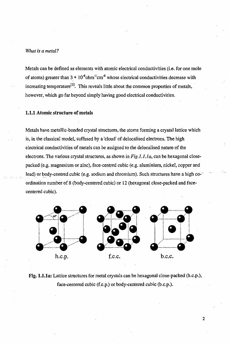
1.1.1 Atomic structure of metals
Metals have metallic-bonded crystal structures. the atoms forming a crystal lattice which
is. in the classical model. suffused by a 'cloud' of delocalised electrons. The high
electrical conductivities of metals can be assigned to the delocalised nature of the
electrons. The various crystal structures. as shown in Fig. 1. 1. la. can be hexagonal close
packed (e.g. magnesium or zinc). face-centred cubic (e.g. aluminium. nickel. copper and
lead) or body-centred cubic (e.g. sodium and chromium). Such structures have a high co
ordination number of 8 (body-centered cubic) or 12 (hexagonal close-packed and face
centered cubic) .
.................. ~:::::::::·:~:.·l~············ I
i .i i i . . . . . . . . : : : :
i &.f ............... : •: ..........•• : ......... . ................ .
~'~"""".~ •.. :.~.: i ... · .. r .... ·.~~ .4:.
i .--41 .... 1 ... . .:: .................. . . .a .... · .......... . .:: ... ! ............... !
I!!L. a: .. · .......... · .. ·a
h.c.p. f.c.c. b.c.c.
Fig. 1.1.1a: Lattice structures for metal crystals can be hexagonal close-packed (h.c.p.).
face-centered cubic (f.c.p.) or body-centered cubic (b.c.p.).
2
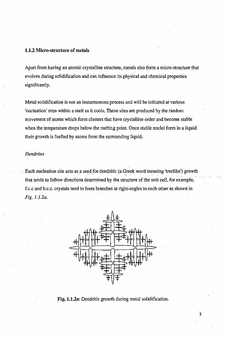
1.1.2 Micro-structure of metals
Apart from having an atomic crystalline structure, metals also form a micro-structure that
evolves during solidification and can influence its physical and chemical properties
significantly.
Metal solidification is not an instantaneous process and will be initiated at various
'nucleation' sites within a melt as it cools. These sites are produced by the random
movement of atoms which form clusters that have crystalline order and become stable
when the temperature drops below the melting point. Once stable nuclei form in a liquid
their growth is fuelled by atoms from the surrounding liquid.
Dendrites
.. Each nucleation site acts as a seed for dendritic (a Greek word meaning 'treelike') growth
that tends to follow directions determined by the structure of the unit cell, for example,
f.c.c and b.c.c. crystals tend to form branches at right-angles to each other as shown in
Fig.l.l.2a.
Fig.1.1.2a: Dendritic growth during metal solidification.
3

Grains
Grain boundaries are formed at the intersection of colliding dendritic growths; thus the
faster the cooling rate, the greater the density of nucleation sites, and the smaller the grain
size]3]. Although often referred to within the context of the microstructure of the metal,
grains can sometimes be seen with the naked eye and may even form as large as a few
centimetres across. Under controlled conditions, it is possible to form single crystal solids
by only allowing one nucleus to grow. Small grains contribute to the hardness of the
metal, a fact exploited by using a 'chill' mould shown in Fig.l.l.2b.
Chill Mould Sand Cast (High Temp.) (Low Temp.)
Columnar Crystals
Temperature Gradients
Fig. 1.1.2b: The effect of mould design on crystal formation in casting. The graphs show
the temperature distribution through a cross-section of the above melts.
Polymorphism
Some metals adopt different crystal structures depending on the temperature they are
exposed to; a phenomena known as 'polymorphism'. For example, polymorphism is
exhibited by iron which is b.c.c. below 910°C ( a.-Fe), f.c.c. between 910 °c and 1400°C
(y-Fe), and reverts back to b.c.c. above 1400°C (3--Fe).
4
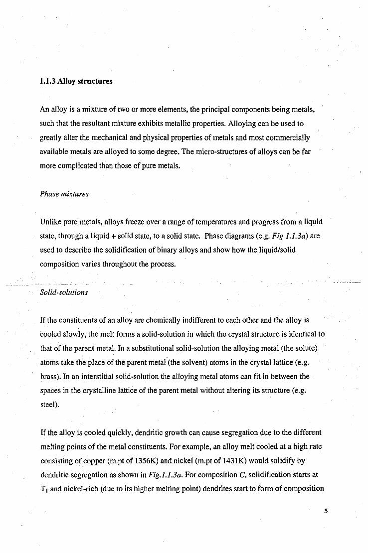
1.1.3 Alloy structures
An alloy is a mixture of two or more elements, the principal components being metals,
such that the resultant mixture exhibits metallic properties. Alloying can be used to
greatly alter the mechanical and physical properties of metals and most commerciaIly
available metals are alloyed to some degree. The micro-structures of alloys can be far
more complicated than those of pure metals.
Phase mixtures
Unlike pure metals, alloys freeze over a range of temperatures and progress from a liquid
state, through a liquid + solid state, to a solid state. Phase diagrams (e.g. Fig 1.1.3a) are
used to describe the solidification of binary alloys and show how the liquid/solid
composition varies throughout the process.
Solid-solutions
If the constituents of an alloy are chemically indifferent to each other and the alloy is
cooled slowly, the melt forms a solid-solution in which the crystal structure is identical to
that of the parent metal. In a substitutional solid-solution the alloying metal (the solute)
atoms take the place of the parent metal (the solvent) atoms in the crystal lattice (e.g.
brass). In an interstitial solid-solution the alloying metal atoms can fit in between the
spaces in the crystalline lattice of the parent metal without altering its structure (e.g.
steel).
If the alloy is cooled quickly, dendritic growth can cause segregation due to the different
melting points of the metal constituents. For example, an alloy melt cooled at a high rate
consisting of copper (m.pt of 1356K) and nickel (m.pt of l431K) would solidify by
dendritic segregation as shown in Fig.l.l.3a. For composition C, solidification starts at
Tl and nickel-rich (due to its higher melting point) dendrites start to form of composition
5

a.leaving the remaining mixture with an increasing copper concentration. The
composition of the solid and the liquid at a given temperature is given by the intersection
of the isotherm with the solidus and Iiquidus lines respectively. As the melt cools to T2.
the composition of liquid becomes d and that of the solid becomes b. In this way a 'coring'
effect is produced where the cores of the dendrites are rich in the high-melting point
metal and the outer parts are rich in the lower-melting point metal. When T3 is reached.
the remaining copper-rich mixture solidifies to form the inter-dendritic alloy of
composition e.
T
Solid Solution (S)
c
Ni 0% --------------. 100%
Fig. 1.1.3a: Dendritic segregation in rapidly cooled. CulNi system.
Solid-state diffusion: the above example describes solidification for a rapidly cooled solid
solution. If the solution is cooled slowly. the process of solid-state diffusion allows atom
migration in the solid-state when near the melting point. This enables the melt to reach
equilibrium and a homogenous solid is formed. For example. an alloy cast using a 'chill'
mould will exhibit coring at the rapidly cooled outer surface. but a more homogenous
interior as it cools more slowly.
No mutual solid solubility
Solid-solutions are uncommon; more often limited solid solubility is encountered and
two-phase microstructures form of different crystalline structure. When completely
6
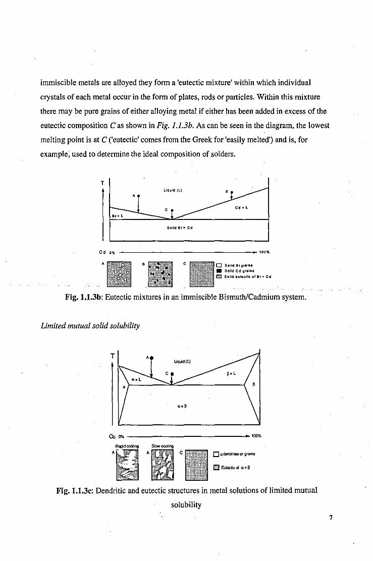
immiscible metals are alloyed they form a 'eutectic mixture' within which individual
crystals of each metal occur in the form of plates, rods or particles. Within this mixture
there may be pure grains of either alloying metal if either has been added in excess of the
eutectic composition C as shown in Fig. 1.1.3b. As can be seen in the diagram, the lowest
melting point is at C ('eutectic' comes from the Greek for 'easily melted') and is, for
example, used to determine the ideal composition of solders.
T
A
c BI + L
SoUd BI + Cd
Cd 0% _________________ 100%
A B c o SOlid BI grain. • SOlid Cd gralu
~ SOlid euteoUc of BI + Cd
Fig. 1.1.3b: Eutectic mixtures in an immiscible Bismuth/Cadmium system.
Limited mutual solid solubility
T A
c •• L
Ou ~ __________________________ b~l00%
Rapd cooling Slow cooling A - A C o adendrites or grains
El Eutectic 01 Cl + ~
Fig. 1.1.3c: Dendritic and eutectic structures in metal solutions of limited mutual
solubility
7

As can be expected, alloys of limited mutual solubility may contain a mixture of dendritic
and eutectic structures as shown in Fig. 1.I.3c. Different phases are assigned a Greek
character prefix.
Other structures, that may depend on specific alloy composition or cooling factors, are
briefly described below:
Eutectoid structures: for certain alloys, phase changes occur in an already existing solid
solution to form eutectoid structures. For example, tin-bronze may form a delta phase of
the inter-metallic compound CU3ISng. Eutectoid structures are important in determining
the properties of steels. In this case, the eutectoid is formed when the gamma phase solid
solution (austentite) decomposes at 727°C to form pearlite, a fine collection of plates of
a-Fe (ferrite) and Fe3C (cementite) phases, as shown in Fig. 1.1.3d.
> B50'c BOO·C 727'c < 727'c
D r grains III pearlite
Fig. t.t.3d: Phase structures in cooling steel.
Peritectic structures: A liquid phase may react with a solid phase to form peritectic
structures. Peritectic reactions may cause precipitation of a new phase within existing
alpha grains or at grain boundaries, giving them rounded corners.
Martensite transformations: Martensite is a collection of fine intersecting needles that can
form if an alloy is cooled very quickly.
8

Widmanstaetten transformations: the precipitation of a solid phase at a high temperature
decomposing at a lower temperature into two solid phases. This precipitation takes the
form of plates or needles at the grain boundaries of the initial crystals.
1.1.4 Corroded micro·structures
Metal microstructure can determine the nature of the corrosion processes at the surface of
the metal and also how corrosion permeates into the bulk of the solid. Corrosion
phenomena can be classified on this basis, as shown in Fig. 1.1.4a. For example, the grain
boundaries may corrode preferentially by inter-granular corrosion, severely damaging the
structural integrity of the metal whilst leaving the majority of the metal intact.
Inter-granular corrosion Uniform corrosion
Intra-granular corrosion Selective corrosion
Pitting corrosion Corrosion products on surface
Fig. 1.1.4a: Examples of the microstructure of corroded metals.
9

1.1.5 Optical properties of metals
A thorough review of the optical properties of metals is required for this study to
understand how the laser will interact with the metals studied. Classical electromagnetic
theory provides a good basis for understanding the optical properties of solids. Not
surprisingly, the electrical properties of a metal are closely related to its optical properties.
Skin depth: the skin depth (8) of a metal is the distance over which the amplitude of an
electromagnetic wave drops to lie" of its value at the surface. We can derive Eqn. 1.1[41
Eqn.1.l
from Maxwell's equations which shows how skin depth is directly related to electrical
conductivity (a) and the frequency of incident radiation (m); I! is the permeability of free o
space and IX is the absorption coefficient of the material. Hence, good electrical .
conductors are generally also highly opaque.
Plasma frequency: further manipulation of Maxwell's equations give relations between
the extinction coefficient (K), refractive index (n) and frequency of incident radiation (m)
as shown in Eqn. 1.2 and Eqn. /.3[51.
Eqn 1.2
and
Eqn 1.3
where 1: is the relaxation time, a constant for a given metal, and COp is the plasma
frequency .
• e is the mathematical constant 2.718 (to three decimal places)
10

1 Transparent region
o~=--==t:::=======---o>
Fig. 1.I.Sa: Index of refraction and extinction coefficient versus frequency for a metal.
The plasma frequency is essentially the frequency above which a metal becomes
transparent, as shown in Fig. 1.I.5a, and can be determined, for good electrical
conductors, from the equation[6]
Eqn 1.4
where N is the number of conduction electrons per unit volume, e the electron charge, m .
the electron mass and Eo the permittivity of free-space. Plasma frequencies for metals are
typically found to be around 1015 5.1, in the visible and near ultraviolet regions of the
spectrum.
Metal n 1C R Rmax
Cu 12.8 64.0 0.984 0.9935
Ag 5.88 76.1 0.996 0.9953
AI 34.3 108 0.989 0.990
Au 8.57 75.9 0.994 0.994
Fe 7.60 27.0 0.962 -Pb 22.3 38.5 0.956 -
Table 1.1: Calculated normal reflectance (R) for metals from nand 1C values at 10.6Ilm.
Rmax is the maximum experimentally measured value.
11

Thus, metals are generally highly reflective in the infrared and have a low reflectivity in
the ultraviolet. Qualitative agreement for these predictions of classical theory is
particularly good for the better electrical conductors such as gold, silver and copper, as
shown in Table I.Pl. Determination of the plasma frequency of different metals allows
us to predict how different types of laser radiation are likely to interact with them: heating
effects from an ultraviolet laser beam incident on a metal surface will be more significant
than by an otherwise identical infrared laser beam due to the decrease in reflectivity of
metals in the UV region of the spectrum.
Factors affecting reflectance and absorptivity
The reflectance (R) of a metal can be approximated to[51:
Eqn 1.5
In practice, metals rarely exhibit the reflectance values expressed in Table 1.1 due to a
variety of factors which influence the optical properties of a metallic surface as described
below. It should be noted that an apparently small decrease in reflectance, for example,
from 0.99 to 0.98, appears more significant when expressed in terms of the absorptivity
(A = l-R), which doubles from 0.01 to 0.02.
Surface temperature: A simple relationship can be derived for the increase in absorptivity
(A) with temperature(T)[81:
Eqn 1.6.
which is in good agreement with observations made on pure metals. The absorptivities of
metals can double over an increase in temperature of a few hundred degrees.
12
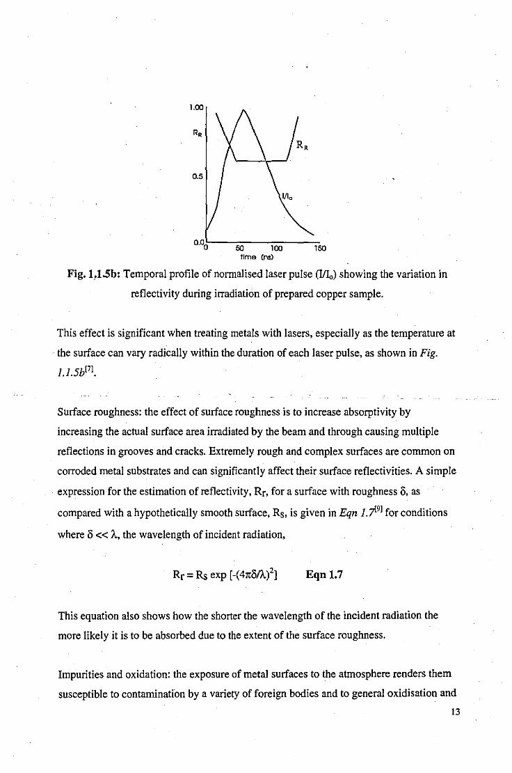
O.OO!:---SO----lOO-----lSO
tIme (ns)
Fig. L1.Sb: Temporal profile of normalised laser pulse (IlL,) showing the variation in
reflectivity during irradiation of prepared copper sample.
This effect is significant when treating metals with lasers, especially as the temperature at
the surface can vary radically within the duration of each laser pulse, as shown in Fig.
1.1.5b[7].
Surface roughness: the effect of surface roughness is to increase absorptivity by
increasing the actual surface area irradiated by the beam and through causing multiple
reflections in grooves and cracks. Extremely rough and complex surfaces are common on
corroded metal substrates and can significantly affect their surface reflectivities. A simple
expression for the estimation of reflectivity, Rr, for a surface with roughness 0, as
compared with a hypothetically smooth surface, Rs, is given in Eqn 1.j>l9J for conditions
where 0 « A., the wavelength of incident radiation,
Rr = Rs exp [-(41t0/A./] Eqn 1.7
This equation also shows how the shorter the wavelength of the incident radiation the
more likely it is to be absorbed due to the extent of the surface roughness.
Impurities and oxidation: the exposure of metal surfaces to the atmosphere renders them
susceptible to contamination by a variety of foreign bodies and to general oxidisation and
13
corrosion. The extent to which the absorptivity of the metal is increased by the presence
of these species depends on their volume and optical properties.
Corrosion: prolonged exposure of metal surfaces to an aggressive environment (e.g.
outside) can cause the formation of corrosion layers a few microns in thickness. Under
such conditions, the optical properties of the metal can be completely shrouded by the
corrosion layer which may entirely absorb the incident radiation.
1.2 Metals in Sculpture, Historical Artefacts and Modern Industry
1.2.1 Introduction
Casting is, and has always been, the most popular method for producing metal sculpture,
although there are many ex~mples ofsculpture_formed}rolllmetalsheet. Recent advances_ ..
in metallurgy (aluminium was discovered as late as 1808 and commercial production was
not until 1886), have resulted in over 20,000 alloys in present use. The metallurgy of a
metal or alloy depends not only upon its composition, but also on the method of
production. The properties of a cast metal wiIl vary greatly from sheet metal.
1.2.2 Cast Metals
. A brief history of copper alloys
Evidence for the smelting of copper has been dated as early as 7000BC from slags
excavated from Southern Anatolia and consistent bronze pr?duction dates back as far as
2800BC in Egypt, India and Mesopotania. Alloys of similar composition to modem
gunmetals were being cast before 1000BC. Ancient Rome found many diverse
applications for bronze, including cutlery, needles, jewellery, containers, coinage, knives,
razors, tools, musical instruments and weaponry. Brass was not produced deliberately
14

until the Middle Ages due to the late discovery of zinc. Brass became particularly popular
in Elizabethan times when it was exploited for its yellow coloration for purposes of
ornamentation.
Casting was probably the first form of chemistry - the word chemistry is derived from the
Greek 'chyma', meaning casting. Although casting techniques have a history of thousands
of years. the most popular method, since it was first tried in ancient India and Egypt, has
been that of lost-wax casting. Since then it has been used to create the great sculptures of
the Shang, Chou and Han dynasties of China, of Nara and Mamakura in Japan, of Ife and
Benin in Africa, of the Golden Age in Greece and Imperial Rome and of Renaissance
Italy[lOl. Lost-wax casting is still the most popular form of casting today.
Lost-wax casting
. "The skill of the Chinese bronze-worker in casting large quantities of metal is aptly
illustrated by the Great Bell of Peking. reputed to weigh sixty-five tons. The bell was
cast in the reign of Yung-Lo (1403-24). and it is related that the first attempts to cast
it by the cannon-founder, Kuan Yu, were unsuccessful. One of Yung-Io's daughters,
Ko-ia, sacrificed herself by throwing herself into the crucible just as the metal started
to flow, leaving behind her shoe in the hand of an attendant who tried to restrain her.
The bell was cast successfully, but when it was struck its deep note was followed by
a wailing sound in which the word hsieh could be heard. It was Ko-ia wailing for her
lost shoe. ,,[IOJ
The method of lost-wax casting does not produce a homogenous material, but one of
varying constituency and grain structure on both macro and micro-scales due to the
process of crystal growth in a mixture of metals during solidification. The precise
composition of the alloy (very variable, especially in ancient bronzes) and the cooling
conditions have a fundamental effect on the properties of the cast alloy. Although the
Great Bell of Peking is an extreme example (see above), the composition of a given
bronze. or any given alloy. may vary considerably. Varieties of composition may be
deliberate, by means of following one of the hundreds of different alloying "recipes", or
15

simply by the addition of various scrap metals in times when following recipes was either
too expensive, as yet unknown, or simply not bothered with. As a result, the metallurgist
has to deal with alloys that vary in composition from piece to piece.
The composition of copper alloys
Sculpture is almost invariably cast in bronze, and it is for this reason that the majority of
our attention shall be focused upon bronzes. The popular conception that bronze is an
alloy of copper with tin is over-simplistic and, although these two metals are necessary
ingredients, many more are normally present. A popular bronze used for casting
sculpture, such as gun-metal bronze, may contain a cocktail of fourteen or more different
ingredients (see Appendix C). Some ofthe more common metals found in copper alloys
are described below.
Copper: although over 160 copper minerals are known, most are rare and almost all
copper is extracted by smelting copper sulphide minerals. Copper is a soft metal and
difficult to machine but readily forms alloys, the properties of which can be tailored to the
requirements ofthe application to improve hardness and machinability[II.151.
Tin: 'true' bronzes contain between 5-15% tin. Most ancient bronzes have less than 17%
tin (the limit of th~ solubility of tin in copper-rich solid solution). A higher proportion of
tin makes the bronze very difficult to work, although a high percentage of tin has been
found in ancient bronzes to produce a 'white' bronze for mirrors (e.g. speculum contained
up to 35% tin and was popular in Rome). The aptly named bell-metal (79%Cu, 21 %Sn)
has good sonorous properties.
Zinc: brass is a copper alloy with zinc as the secondary ingredient to form a hard and
strong alloy. To form brass, zinc ore and copper ore are mixed and smelted together to
avoid the loss of zinc, which boils at 907°C. There are basically three types of brasses
(depending on the phase type): alpha-brasses with up to 35% zinc; alpha + beta brasses
16

with between 35% and 46.6% zinc; and beta-brasses with between 46.6% and 50.6%
zinc. Gilding metals are brasses with less than 20% zinc. The brass becomes harder and
more brittle as the zinc percentage increases; most ancient specimens are alpha-brasses.
Lead: lead is a common addition (typically less than 4%) to many tin-bronzes principally
to infiltrate and fill pores formed by shrinkage during solidification, thus improving
machinability. When cast with low-tin bronzes the lead does not alloy (Le. is completely
insoluble) with the copper or tin, but forms fine globules randomly distributed throughout
the structure. The addition of lead to tin-bronzes significantly lowers the melting point of
the alloy and can have a variety effects on the grain and dendritic structure.
Nickel: the inclusion of between 10% and 30% nickel to copper alloy is carried out to
improve corrosion resistance, particularly to salt water. This fact, coupled with the ability
for copper-nickel alloy to resist biological growth has seen its growth in the use for
cladding for the hulls of ships.
Phosphorous: rarely exceeding I % of the composition, phosphorous can increase the
hardness of copper alloys.
Arsenic: the addition of arsenic to alloys containing zinc can improve corrosion resistance
by preventing dezincification (the sacrificial loss of zinc in preference to copper from the
surface of the alloy). Commonly found in ancient bronzes, the arsenic can segregate
during casting (a process known as 'sweating') to form a sil very coating of an
intermetallic arsenic compound.
Antimony: like arsenic, antimony has been found to form intermetallic silvery coatings on
ancient bronze.
Manganese: added to copper alloys to increase tensile strength and also give a 'chocolate'
bronze appearance to the alloy.
17

Gold: Japanese copper alloys, such as shakudo, contained up to 5% gold and its
patination qualities were exploited to produce rich colours. Tumbago was a copper/gold
alloy used for both casting and sheet-metal work in South America.
Silver: another popular Japanese alloy, shibuichi, comprises of copper with between to
and 40% silver and also offers valuable patination possibilities.
Aluminium: an addition of 9-11 % aluminium to modern bronzes can improve corrosion
resistance and also resistance to erosion and wear.
Other metals and alloys used in sculpture and casting
Iron and steel: found applications in the manufacture of armour and armoury, as well as
household utensils. The precise nature of a steel is dependent on the carbon content and
the cooling process. Steels increase in hardness with carbon content until the limit of
solubility is obtained at 1.7%.
Pewter: ancient pewters were alloys of lead and tin, although modern pewters are alloys
of lead, antimony and copper. The oxide coating that forms on exposure to the air has
protective qualities and is considered desirable[l6J.
Silver: is often combined with copper as an alloying element. Sterling silver may contain
up to 10% copper.
Gold: the use of gold in gilding bronze sculpture was popular in ancient Greece and
Rome to provide a protective and attractive coating with the appearance of gold. Evidence
of gilding rarely survives due to detachment from the base metal caused by interfacial
corrosion processes and examples of its preservation are all the more valuable because of
this. Gold is often alloyed with silver to form electrum for colour variation and economic
purposes.
18

1.2.3 Worked metals
A worked metal or alloy is one that has undergone some morphological process, such as
hammering, turning, drawing, and so forth, that has altered its properties. Metals may be
cold-worked or hot-worked.
Cold-working: the grains that exist in a metal become deformed by cold-working
processes, such as hammering, which generate dislocations in the crystal structure.
Dislocations have difficulty moving across grain boundaries and therefore, if the grain
size is small, the metal becomes progressively more brittle as it is 'work-hardened'.
Alpha phase dendrites with eutectic fill in typical cast alloy
Elongated denritic remnants after heavy working
Fig. 1.2.3a: Grain structures in cast and worked alloys
Hot-working: work-hardened metals can be softened by heating the metal to a
temperature between one third and one half of its melting point (a process known as
annealing) to induce recrystalJisation of the grains. Hot-working is a combination of the
effects of cold-working and annealing and produces no work-hardening. Many forging
operations use hot working to effect initial shape changes with minimum expenditure of
energy followed by cold-working processes to work-harden the metal and give a good
surface finish[17J. Thus, we can expect the grain size to be much smaller, and dislocation
densities much Iiigher, in worked metals and alloys (such as sheet metal) than those that
have been cast, as shown in Fig. 1.2.3a.
19

1.2.4 Present day metals and alloys
Steel: is used in applications where hardness and durability are required. Plain carbon
steels contain up to 1.7% carbon and significant amounts of manganese residual from the
deoxidation process. Above 910°C, pure iron has a face-centre cubic structure that can
dissolve up to 1.7% carbon. Below 910°C, iron has a body-centre cubic structure that can
dissolve only 0.03% carbon and thus precipitation effects create various transformations
on cooling. Carbon precipitates as cementite (Fe3C), a very hard compound that increases
the hardness of the steel. The hardness of the steel determines the application to which it
is best suited; structural applications, machine parts, tools, springs, blades, vehicle body
work and many other areas[l8J. Surface treatments can be applied to steels with poor'
engineering properties to improve the surface hardness, durability and corrosion
resistance.
Aluminium and aluminium alloys: although aluminium is the most common metal on
earth, its high reactivity prevents large scale production by smelting methods (smaIl
amounts were produced by reduction of sodium by the mineral bauxite from 1825) and it
was not until 1886 that the electrolysis of purified alumina formed the basis for large
scale production. Although casting is still performed on a large scale, most aluminium is
marketed in sheet form and, to a lesser extent, as extruded bars and tubes[19J. Aluminium
is capable of dissolving elements such as copper, silicon, magnesium, manganese, zinc,
titanium, cadmium, columbium, nickel, cerium, tin, lead and others which are generaIly
added to form an aIloy of increased strength and decreased ductility. The strength,
lightness and corrosion resistance of aluminium has found it many applications in
aerospace and transport in general, building and architecture, and domestic appliances[20J.
Copper and copper aIloys: the high electrical conductivity and ductility of copper has
found it many applications in the transmission of electricity and over a third of all copper'
produced is used in the area of electrical engineering. Another major use for copper (and
copper-nickel) is in buildings due to its corrosion resistance and its potential to form
20

attractive patinas. Sheet copper has also been used in sculpture, such as the Statue of
Liberty.
Surface treatments
The hardness, wettability, adhesive properties, corrosion resistance, and appearance of
metals are all dependent to some extent on their surface properties. Modern surface
treatments enable manufacturers to improve the surface characteristics of metals for their
particular application without significantly altering the properties of the bulk material. It
is the surface of the metal that is subjected to environmental influences and determines
how the metal will behave when exposed to different conditions.
Pickling and cleaning: cleaning is the removal of oil, grease and dirt from the surface of
the metal by dipping in organic solvents or hot alkali solutions. Pickling is the removal of
.. oxide layers by the use of acidic solutions[211. The combination of cleaning followed by
pickling is a common pretreatment in industrial processes prior to electroplating, or
application of paint or adhesives, the quality and durability of which are most dependent
on effective pretreatment processes.
Plating, galvanising and coating: coating a metal with a less-noble metal can offer
protection to the bulk material if the coating metal is chosen such that it forms a
sacrificial passivating film of corrosion. Zinc is often applied to steel surfaces by hot-dip
gal vanising, electroplating or spraying. The application of a suitable paint to the zinc
surface can form a 'duplex system' that can further extend the life to 1.5-2.5 times that of
the individual systems[221.
Abrasive treatments: abrasives, such as sand-blasting, have the effect of cleaning-off
contamination and also texturing the surface. A textured surface provides a large surface
area for adhesion and may also increase the number of polar groups available for coating
attachment[231.
21

Laser treatments: these include laser transformation hardening (LTH), laser surface
melting (LSM), laser surface alloying and c1adding[241. LTH and melt-solidification has
been shown to give stainless steel a three fold increase in fretting wear resistance[251.
Surface structures produced by excimer laser ablation can increase surface area and
adhesive properties of metals[261. LSM has been shown to improve wear and corrosion
resistance and refines grain size[271.
Phosphating: phosphate coatings can be applied to zinc, steel and aluminium substrates as
a form of protection against corrosion and wear. They are particularly favoured as
pretreatment processes for organic coatings as they provide an active surface for
adhesion[281.
1.3 Corrosion and patination
Jean-Paul Sartre once wrote-of a weathered sculpture:
"He has no eyes, scarcely any nose, a beard eaten away by that strange leprosy
which sometimes descends, like an epidemic, on all statues in a particular district.
He looked sick[y and evil.,,!29]
It is clear to see how the artistic integrity of the piece has been compromised through the
action of corrosion, and what was once intended to be a monument to the achievements of
Impetraz, poet and writer, presents an image of something to the contrary. Since Sartre's
novel, first published in 1938, the leprosy to which he refers, spawned and perpetuated by
the industrial revolution, can be observed to be attacking most of the outdoor sculpture of
the worlds' cities today.
22

1.3.1 The Corrosion Process
It is generally recognised that corrosion takes place by an electrochemical process.
Faraday's Law of Electrolysis states that the chemical change produced by a steady
electric current is proportional to the number of coulombs which have passed. Thus, the·
amount of metal deposited at a cathode or dissol ved at an anode is proportional to the
current and time. The current is in turn equal to EIR where E is the E.M.F. in volts (in
general, this varies with time due to polarisation effects), and R is the sum of the
resistances between the metallic and liquid parts of the circuit.
Thus. the normal electrode potential of a given metal defines its reactivity and general
susceptibility to corrosion (see Appendix A).
Electrochemical corrosion
Bimetallic systems: corrosion in the presence of dissimilar metals is facilitated by the
presence of an electrolyte (e.g. rainwater). Different metals have different affinities for
electrons. a more noble metal (e.g. copper) will tend to absorb electrons from a baser
metal (e.g. iron). Thus. the noble metal becomes the cathode and the base metal the
anode. Anions and cations in the solution are attracted to their respective electrodes. as in
an electric cell. see Fig 1.3.1a.
Anode 2:.J::lI--r- Cathode
Fig.l.3.1a: A simple electrochemical cell
23

At the anode: atoms of the electrode will be deprived of electrons and enter the electrolyte
as cations. The oxidation state of the ions will depend on the current density (e.g. Fe++
ions produced at low current density, Fe+++ ions produced at a higher current density).
These ions may form soluble or insoluble corrosion products. Unless the corrosion
products form an adherent coating to stifle the reaction, the anode will be gradually eaten
away.
At the cathode: the reactions at the cathode are very much dependent on the presence of
dissolved oxygen in the electrolyte. With no oxygen present, the supply of electrons
combine with hydrogen ions to produce hydrogen gas. In the presence of oxygen the
electrons combine with it and water to form hydroxide ions. Both reactions increase the
concentration of hydroxide ions in the solution and therefore can be considered as
alkaline reactions; they do not produce any corrosion of the cathode in themselves.
Bimetallic systems are common in sculpture; micro-cells may evolve between alloying
components and phases; or large cells may form between dissimilar metals used for repair
work, welds, support bolts, or different parts of the sculpture itself. However,
electrochemical corrosion does not necessarily require the presence of more than one
metal.
Single-metal electrochemical action
. Electrochemical corrosion occurs in single metal systems due to a potential forming
between the metal anode and a cathode that may be an impurity in the metal, surface
contamination, or surface corrosion products, see Fig 1.3. lb. The process then proceeds
as with the bimetallic system. Variation in oxygen concentration in the electrolyte can
also create a potential difference to facilitate electrochemical processes: aerated portions
of electrolyte (i.e. submerged but near the water-line) can behave as a cathode towards the
anodic, 'unaerated' portions.
24

Fig. 1.3.1b: Electrochemical corrosion in single metal systems.
The effect of corrosion products on corrosion
From the onset of electrochemical corrosion a complex, dynamic system evolves, the
nature of which is affected by the corrosion products that form. This complexity has
provided the fuel for much research and cannot be considered here in its entirety. In
general, however, for a given electrolyte, corrosion products may form passive coatings
that inhibit further corrosion or aggressive coatings that perpetuate further corrosion. It
should be noted, however, that terming a corrosion layer 'passive' or 'aggressive' should be
done with care as its protective qualities can be very sensitive to changes in the system
and most corrosion layers will have a mixture of passive and aggressive components.
Some metal oxides that are insoluble in pure water will become soluble in rain-water.
Passive coatings: the term 'passive' has been subject to varying definitions and shall be
. used here to represent the quality of a coating that inhibits further corrosion under
conditions to which it is likely to be exposed[301. A passive film is an insoluble film that
forms through the corrosion process and presents a barrier between the electrode and
electrolyte, stifling ionic ( and electronic) transport between them, thus reducing the rate
of corrosion as defined by Faraday's law. The influence of passive films can be extremely
significant: in the case of aluminium (very low in the electrochemical series, see
Appendix A), the passive alumina (Ah03) film that forms on exposure to air renders it
protected from certain acids that actively attack 'less reactive' metals such as iron and
zinc.
25
Aggressive coatings: films may form that are insoluble but do not prevent ion migration.
These have no significant stifling effect but may provide a cathodic region to encourage
further electrochemical attack. Such coatings are responsible for low corrosion resistance
of iron. When iron is exposed to water, the cations from the anodic region will pass into
the solution as soluble Fe(OHh. This primary corrosion product will be later oxidised (by
oxygen in the water) to precipitate insoluble FeO(OH) (a secondary corrosion product)
that is not immediately in contact with the metal surface and thus forms a friable,
permeable coating responsible for the majority of the loosely adherent 'rust' commonly
seen on iron structures.
1.3.2 Factors affecting metal corrosion
With few exceptions, metals are wrought from mineral deposits and it is to these that they
revert on exposure to the atmosphere. The energy required to reduce metallic ore makes it
energetically favourable for a metal to oxidise if placed in an oxidising atmosphere. The
chemistry of corrosion products and rate of corrosion is dependent on the metal and
environment, as described below:
(i) The Metal
Apart from obvious variations in the corrosion products from different metals and alloys,
even very slight discrepancies in composition, grain size, impurities, surface roughness
and topography can have pronounced effects on the corrosion products. '
Composition: for example, even trace quantities of arsenic and bismuth can significantly
encourage the growth of a protective film on sheet copper[31].
Grain-size: there is often an epitactic relation between the cuprite layer and the orientation
of the copper alloy substrate[32]. Nassau found that, under controlled conditions, there
26
existed a direct correlation between grain-size and thickness of an artificially grown
patina!33]. This is supported by observations made on the Statue of Liberty, where
patination was found to be absent on copper panels with a small grain size although it was
present on the rest of the structure!34] .
Impurities: provide cathodic regions for electrochemical attack. Impurities may be present
in the cast metal or as particulate matter that is transferred from the atmosphere to the
surface.
Surface roughness and topography: air turbulence is higher for air flow over rough or
complicated surfaces, thus the transfer of corrosive species from the air to the metal is
higher than for a smooth, simple surface!35]. Surface roughness can also increase
wettability, thus encouraging the presence of rain-water on the surface.
(ii) The Environment ,
Aerobic Corrosion
The rate of outdoor corrosion is very susceptible to weather conditions, particularly the
frequency and chemistry of rain and other forms of precipitation. Of course, environments
vary significantly over the world and are subject to seasonal, geographical as well as
anthropogenic influences. For example, a survey by the United Nations Environment
Program (1980-84) surveyed 54 cities throughout the world and found S02 levels to vary
by a factor of 100 and Total Suspended Particles (TSP) varied by a factor of 200. In
London, S02 and TSP levels have gradually increased from 1500 A.D. to 1900 A.D., after
which they have gradually declined!36].
Wind: Vemon(3)] observed that copper exposed to prevailing winds forms a more
uniform, green layer of corrosion than sheltered copper areas, which remains green and
black. Winds accelerate the transfer of particles to the surface of the metal and the rate at
27

which rain-water evaporates from the surface, both of which can affect the corrosion
process.
Time-of-wetness: 70% humidity is required for the corrosion rate to be significant.
Corrosion by electrochemical processes is made possible by the presence of a thin film of
impure water on the surface of the metal to act as an electrolyte. The time-of wetness is
significantly dependent upon the relative humidity, duration and frequency of
precipitation; temperature of the air and the metal; chemistry of the corrosion products;
wind-speed; and hours of sunshine[37].
Composition of surface electrolytes: clearly, the composition of corrosion products will
depend on the chemical species di~solved in the electrolytes and their respective
concentrations. Oxygen is responsible for high rates of cathodic reaction, its concentration
becomes a maximum when the electrolyte layer becomes very thin, just before it dries.
The presence of S02 in the atmosphere is common through the combustion of fossil fuels
and it is oxidised by a series of processes to form corrosive H2S04. N02 is a relatively
inert gas but often present in significant quantities and has been shown to havea
synergetic effect with dissolved sulphates by increasing the oxidising power of the
aqueous environment[381. Whereas S02 delivery to the surfac:e is strongly enhanced by the
presence of water, N02 is essentially repelled by wet surfaces[351. Chlorides can be present
in marine air, in the form of NaCl and KCl, or from combustion of coal or waste, in the
form of HC!. Chlorides are responsible for self-perpetuating corrosion phenomena on
both iron and copper alloys[391. Even if present in ppm, HCl can accelerate corrosion
processes enormously[401. Ozone, ammonium and bicarbonates also influence the
corrosion process.
Pollutants and suspended particles: even insoluble particles, e.g. soot, alumina and sand
can affect corrosion process[41 1. Hard particulates, such as those containing silica and
alum in a, can 'sand-blast' the metal. Insoluble particles on the surface can act as a cathode
for electrochemical attack, see Fig. 1.3. lb. Reduced sulphur gases, such as H2S produced
28

by mills, marshes and sewage treatment plants, can attack metals in the absence of water.
Hygroscopic particles can enhance the deposition of atmospheric gases onto the metal
surface. Large particles are prevalent on skyward facing surfaces due to the effect of
gravity.
Location: the corrosivity of the atmosphere for a given sculpture depends very much on
its location, whether in a urban, rural or coastal setting[42.43]. The prevalence of emissions
from industry and exhausts in urban surroundings contributes many potentially corrosive
species to the environment such as (S04)"-, (N03)", (NH4t, cr, S--, various organic acids
and inert particulate matter. Concentrations tend to be much lower in rural areas, although
inert particulate matter can be generated through various agricultural practices. Coastal
atmospheres have a predictably high concentration of chlorides due to sea-salt. Even
sculpture that has been stored for transfer to a museum environment may be subjected to
chemical attack. Antiquities stored in wooden cabinets are prone to attack from acetic
acid and formaldehyde derived from the woods, coatings and adhesives used in their
manufacture[44] .
Temperature: the rate of chemical reactions increases with temperature in general.
Temperature can vary by as much as 20°C over the surface of a sculpture at a given
time[45].
Light: non-corrosive N02 has been known to be converted to corrosive HN03 by
photochemical oxidation[37].
Anaerobic Corrosion
The exclusion of air from the surface of a metal artefact (e.g. by burial) generally retards
corrosion processes. Indeed, the excavation of an object and its subsequent exposure to an
oxidising atmosphere can activate redundant corrosion mechanisms and an artefact that
has been buried for 2000 years can become completely destroyed 40-80 years after
29

excavation[461. As a result, many excavated objects require some form of stabilisation if
the deleterious effects of moisture, oxygen and residual chlorides are to be avoided[471.
Clearly, buried artefacts will not generally suffer the rapid, chaotic environmental
fluctuations endured by those in outdoor conditions and the corrosion process is more
likely to be determined by the chemical properties of the impacting material, especially
the acidity/alkalinity of the soil (see Appendix F). For example, the composition of loess'
is responsible for the formation of a desirable lilac patina on Chinese silver from the
T'ang dynastyl481.
1.3.3 Species of corrosion product.
As can be expected from the wide variety of metals and alloys requiring conservation, and
the sensitivity of corroding systems, the diversity of corrosion products is considerable,
even over the surface of a single artefact. A study of sixteen bronze monuments in close
vicinity to each other around Ottawa, Canada, revealed the presence of 94 different
corrosion products resulting from 168 surface scrapings[50I. Despite this complexity,
generalisations can be made and certain corrosion products dominate and merit most
attention. Knowledge of the type and nature of corrosion products is vital for a complete
study and evaluation of conservation processes. Certain corrosion products are stable and
passive and inhibit further corrosion. Others are aggressive and encourage further
corrosion of the metal substrate. Clearly, the appearance and nature of corrosion products
will determine whether a conservator would wish to remove or retain part or all of the
corrosion layer.
Structural variations
. Corrosion products can form single, homogenous layers of corrosion, such as the passive
Ah031ayer commonly found on aluminium. Very often, however,corrosion products can
form as two or more layers, as is common with copper and its alloys, see Fig l.3.3a. It is
• Loess is an alkaline soil common to north central Europe. China. the American West and other areas["].
30
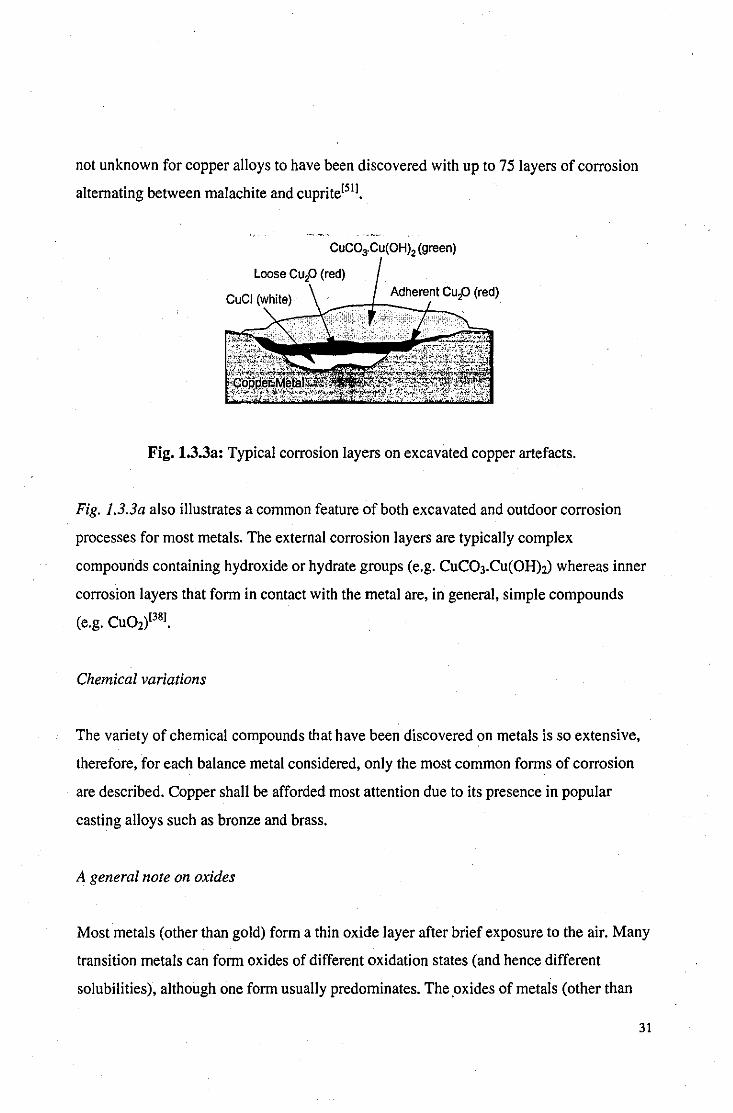
not unknown for copper alloys to have been discovered with up to 75 layers of corrosion
alternating between malachite and cuprite[511.
Fig. 1.3.3a: Typical corrosion layers on excavated copper artefacts.
Fig. l.3.3a also illustrates a common feature of both excavated and outdoor corrosion
processes for most metals. The external corrosion layers are typically complex
compounds containing hydroxide or hydrate groups (e.g. CuC03.Cu(OH)2) whereas inner
corrosion layers that form in contact with the metal are, in general, simple compounds
(e.g. CUOd381.
Chemical variations
The variety of chemical compounds that have been discovered on metals is so extensive,
therefore, for each balance metal considered, only the most common forms of corrosion
are described. Copper shall be afforded most attention due to its presence in popular
casting alloys such as bronze and brass.
A general note on oxides
Most metals (other than gold) form a thin oxide layer after brief exposure to the air. Many
transition metals can form oxides of different oxidation states (and hence different
solubilities), although one form usually predominates. The .oxides of metals (other than
31

alkali and alkaline earth metals, and thallium) are sparingly soluble in pure water and
hence can provide a protective coating against corrosion. Oxides of the form MO (where
M is any metal) become soluble in acidic solutions, such as rainwater, although the
acidity of the solution rapidly decreases in the vicinity of the anode during the corrosion
process. Sesquioxides (Le. those of the form M203) are only sparingly soluble in acids
and therefore form the most effective passive oxide layers, such as alumina layers that
passivate aluminium or magnetite layers on steel.
Copper
Oxides: a copper oxide layer most often forms as cuprite (CU20), although tenorite (CuO)
may be found under certain conditions, such as high temperatures. Oxides often form an
interfacial layer between the metal substrate and more complicated external corrosion
products. Oxides can form an acceptable patination layer for copper and copper alloys[52];
a familiar example might be the oxide on the bronze lions under Nelsons Column[531.
Oxides were particularly popular as an artificial method of patination in the 17th Century
with sculptors such as Bernini, who described the presence of a translucent lustrous
brown cuprite layer as the 'naturar colour of bronze[54]. It is perhaps interesting to note,
that at the time Bernini made the observation, the lack of S02- in the atmosphere
probably meant that the green patination that we are used to today was something of a
rarity compared with the brownlblack oxide layers that form in its absence. It is rather
ironic that the often termed 'naturar greening of bronze in the present environment is
largely due to the presence of anthropogenic sulphur dioxide in the atmosphere.
Hydroxides: a copper hydroxide is an unstable corrosion product not found under aerobic
conditions[55] and when excavated from anaerobic conditions it is frequently transformed
to atacamite (basic copper chloride) within hours[56].
Sulphides: copper sulphides are often present on prehistoric bronze objects found in bogs
as a result of H2S produced by. sulphate-reducing micro-organisms in anaerobic
32
conditions[57J. Sulphides may take the fonn CU2S (chaIcocite), CUl.96S (djurleite), Cul.sS
(digenite), CuS (coveIIite) and CUl.6S (geerite) and removal is generally favoured.
CoveIIite and chalcocite have been occasionally found in urban areas[5SJ.
Basic sulphates: the relatively high concentrations of S02" in urban areas, the
insolubility' of the basic sulphate, and the extensive conditions under which it can fonn
and remain stable makes basic copper sulphate, CU4S040H6 (brochantite), a very
common corrosion product on copper and its alloys. First correctly identified by Vernon
and Whitby in 1929[31J, brochantite was found to be responsible for the green coloration
of most outdoor bronze sculpture previously assumed to be due to the basic carbonate.
The time required to fonn a brochantite layer is subject to great variation: long tenn
exposure tests perfonned by Mattsson and Holm[43J on 36 varieties of copper and copper
alloys showed signs of greening within seven years of exposure to marine and urban
atmospheres, whereas their was no sign of greening on the rural samples. In the early part
of this century, a Danish saying existed, 'When a young architect covers his roof with
copper it will turn green when his hair turns grey,[59J. Many authors have commented on
the value of the protective and aesthetic qualities of unifonn brochantite coatings[31.60.6IJ
and there is a general consensus that, if unifonn, they should be retained. However, a
uniform brochantite coating usually fonns only on wrought copper (e.g. copper sheet) and
the brochantite coatings on cast copper and its alloys (such as form the majority of
outdoor sculpture) are often discontinuous and blotchy[40J. Recently, concerns over the
susceptibility of brochantite to be converted to antlerite (Cu3(OH)4S04), a more soluble"
basic sulphate offering less protection[62J, have brought into question the stability of
brochantite in modern environments. Brochantite has been shown to be unstable if in
direct contact with the copper metal[63J although interfacial corrosion products often
prevent this. The artistic merit and protective qualities of non-unifonn brochantite layers
remain a subject for discussion .
• The solubility constant. K. ofbrochantite is given by log K = .68.91601 • .. The solubility constant, K, of antlerite is given by log K = .47.1 1601•
33

Sulphate hydroxide hydrates: various hydrated basic sulphates form on copper and its
alloys, but are quite uncommon[64J.
Chlorides: nantokite (CuCI) commonly forms on copper and its alloys between the oxide
layer and the metal. The highly corrosive properties of chlorides is due to their high ionic
and electronic conductivities[38J as well as their ability to form soluble complexes, as in
'bronze disease,[47.65J, a self-perpetuating corrosion phenomena caused by nantokite in the
presence of water that gradually eats away at the metal, see Eqn 1.6[66J. The process is
auto-catalytic because the acid that is liberated during the reaction is free to attack more
metal.
2CuCI(s) + H20{l) ~ CU20(s) + 2HCI(aq)
and
2HCI(aq) + 2Cu(s) + '/,02(g) ~ 2CuCI(s) + H20(l) Eqn 1.6
Basic carbonates: although rare to form on outdoor sculpture, basic copper carbonates,
such as malachite (CU2(C03)(OHh), are extremely common on excavated copper
artefacts[67J. A basic carbonate layer is usually stable and often defines and retains the
original surface of the artefact and therefore is rarely removed.
Basic chlorides: as with basic sulphates, the presence of chlorides in the atmosphere and
the insoluble' properties of basic chlorides make them a common component of corrosion
products, particularly in marine areas. Atacamite (a-Cu2(OHhCI) is especially common
on copper and its alloys; less so, paratacamite (y-Cu2(OHhCI). For brass, the most
common basic chloride[68J, anarakite, and has the formula (Cu,Zn)(OHhCI. As with
brochantite, anarakite has been shown to be unstable when formed in direct contact with
the metal[63J .
• The solubility constant. K. of ataeamite is given by log K = .69.8 [60J.
34
Iron
Oxides: wuestite (FeO), hematite (Fe203) and magnetite (Fe304) are the most common
oxides of iron. Magnetite, due to its resistance to acids and black coloration, is sometimes
retained as patination.
Hydroxides: iron and steels tend to form soluble hydroxides, as opposed to oxides, in the
presence of water as their primary corrosion product, and this reduces their resistance to
corrosion[691. These hydroxides precipitate oxide hydroxides on reaction with oxygen.
Oxide hydroxides: oxide hydroxides are insoluble and form as secondary corrosion
products (i.e. loosely adherent rust) on iron and steel which may contain ~-FeO(OH)
(akaganite), a-FeO(OH) (goethite) ory-FeO(OH) (lepidocrocite) forms of the
compound[701. Akaganite has been known to host aggressive chlorine compounds within
its structure[71] and the removal of oxide hydroxides in general is usually desirable as they
have little aesthetic or protective value and provide cathodic areas for electrochemical
attack. The presence of akaganite is a strong indication that corrosion processes are still
act,ive and steps should be taken to stabilise the layer[721.
Chlorides, chloride oxides and hydroxides: the presence of chlorides on iron is
responsible for post-excavation corrosion processes that frequently destroy iron objects
that have survived thousands of years of burial within a few decades[461. Chlorides may
take the form of insoluble FeOCl, FeCh and 2FeCh.5H20. Keller showed that the
presence of chlorine is necessary for the formation of akaganite[731. Removal of chlorides
is often the primary objective of iron conservation.
35

Silver
Oxides: silver does not form oxides in pure air or oxygen at room temperature and
requires heating to 200°C before a film of Ag20 forms. The oxide has little protective
value and is readily converted to sulphides and chlorides.
Sulphides: under aerobic conditions, sulphides rarely form in preference to sulphates on
most metals, apart from in the case of silver. Silver sulphide has a very low solubility in
water and acids. Acanthite (Ag2S) is the most common form of corrosion product on pure
silver, especially in urban atmospheres, and a uniform, shiny black patina of the sulphide
may be considered desirable[741.
Chlorides: chlorargyrite (AgCI), commonly known as 'horn' silver, is often found on
silver artefacts. Silver chloride can undergo photo-reduction in sunlight to produce silver
metal, this being a fundamental process in photography.
Lead
Oxides: on exposure to air, lead forms insoluble oxides Pb03 and Pb02 in the form of
dark grey patination[751.
Hydroxides: lead has the tendency to form partially soluble hydroxides as opposed to
insoluble oxides in the presence of oxygenated water[691.
Carbonates: cerussite (PbC03) is occasionally found on lead and, although insoluble in
water, can be dissolved by weak acids e.g. rainwater. Hydrocerrusite, basic lead carbonate
(Pb3(C03l2(OH)2), is perhaps the most common corrosion product found on lead
artefacts, especially excavated objects. It is insoluble in water and dilute acids but it
usually forms in a powdery form which is unsightly and accelerates the corrosion
36
process(761. The basic carbonate may also appear in a hydrated form
(3PbC03.2Pb(OHh.H20).
Sulphates: angle site (PbS04) is often found on lead[561.
Aluminium
Oxides: alumina (Ah03) is the passive oxide that can often be observed on exposed
aluminium structures.
Hydroxides: gibbsite (Al(OHh) often forms as the major corrosion product on aluminium
in the presence of salt-water1771.
Zinc
Oxides: zincite (ZnO) is commonly found on sculpture although it is easily transformed
into basic compounds that are readily soluble in weak acids and thus has limited
protecti ve properties.
Sulphates: a variety of hydrated sulphates have been found on corroded zinc[561. Basic
zinc sulphate (ZnS04.3Zn(OHhAH20) has been found on pewter artefacts recovered
from ship-wrecks[561.
Tin
Oxides: cassiterite (Sn02) is amorphous and thus escapes detection by many analytical
techniques; it is the most common tin product found on bronze and pewter and is
considered passivating. A partially aerobic environment may produce Sn304 and
occasionally romarchite (SnO) has been found.
37

Hydroxychlorides: a partially aerobic environment may produce Sn4(OH)6CI2 on pewter.
Other metals
Although the above is a fair description of the most commonly encountered corrosion
products, it should be stressed that it is by no means comprehensive and the variety is far
too extensive to be covered in thi~ work. The presence of bone near the corroding metal
(common in burials) may encourage phosphates to form, for example, corrosion products
as complex as sampleite (NaCaCuS(P04)4CI.5H20) have been found on excavated
Egyptian bronzes[781. A large number of mixed metal compounds (e.g. chloroxiphite,
CuPb3Ch02(OHh) are also possible, although uncommon, and are very dependent on the
precise alloying characteristics of the metal.
Factors affecting the colour of corrosion products
The colour of inorganic compounds, particularly that of the transition metals, has long
been exploited to produce pigments for paints and patina. Identification of compounds by
colorimetry is fraught with complexity, however, due to the many factors that affect the
colour of compounds, particularly those which form in impure and variable environments.
Because of this, determination of corrosion compounds from their colour is an unreliable
process and more sophisticated analytical methods are required, such as X-ray powder
diffraction analysis, for precise identification.
Thickness of corrosion films: if a layer of corrosion is very thin (i.e. of comparable
thickness to the wavelength of the light with which it is being observed) then its colour
will depend fundamentally on interference effects produced by the film to such an extent
that the thickness of a given compound may be estimated by its colour (see Appendix B).
38
Size of crystallites: even on thick films, interference effects within the crystallites of the
compound can affect its coloration. For example, cuprite may appear as yellow, red,
brown or black depending on the size of its crystallites.
Impurities and alloying metals: corrosion products of high purity may be produced in
laboratory conditions but rarely form in an outdoor environment. Impurities need only to
be present in very small quantities for significant discoloration to take place and they are
rarely, if ever, completely absent. Impurities will be present in the atmosphere and in the
metal itself and thwart attempts at identification through colour measurements. The
complex composition of many alloys, especially those of copper, also affect the colour of
corrosion.
1.3.4 The value of corrosion
Although corrosion is often regarded as detrimental and undesirable, certain corrosion
products inhibit further corrosion and some also maintain an appearance that is generally
considered attractive and can be highly valued.
Patination: a patina is an attractive, protective inorganic layer that has formed, naturally
or artificially, on the surface of a metal. The word itself is thought to be derived from the
old Italian term 'patena' that referred to a shiny dark varnish applied to shoes[541. FiIiIppo
Baldinucci's 'Vocabolario' of 1681 provides the first known printed reference for the word
and defines patina as 'that general dark tone which time causes to appear on paintings,
that can occasionally be flattering to them'. Since then, the word has been adopted by
conservators to describe a thin, protective and aesthetically pleasing layer in all forms of
art.
39

Artificial Patination
Often an artificial patina is applied at the foundry, a technique that evolved and became
popular in the West between 1880-1914 in Paris by master patinuers, such as the Limet
brothers[54], although the Japanese had perfected many patination techniques centuries
before[lO]. The first evidence of patination appears to be from the third millennium B.C.
on Anatolian metalwork[79]. It is generally recognised that original patina such as these
should never be removed, although they rarely survive on outdoor sculpture as they are
consumed by natural corrosion processes.
Natural patination
Under favourable conditions, a metal sculpture may naturally form a pleasing patina after
prolonged exposure to a satisfactory environment. As the quality of a patina is primarily
a function of its attractiveness, it is also highly subjective: opinions on the correct
appearance of bronze vary with time[54], culture and individual taste. No-one would want
the Statue of Liberty cleaned to a shiny copper and no-one would welcome a uniform,
green patination evolving on the bronze lions under Nelson's Column. Apart from
protective considerations, the question 'what constitutes a patina' should be answered on
an artistic basis as opposed to a scientific one and each example considered on an
individual basis. To a large extent, the sculpture itself determines what type of patina is
most acceptable. Often a desirable patina is accompanied by undesirable corrosion
products that may form above, beneath or within the patina. In these cases, the objective
of the conservator is to remove the undesirable corrosion products whilst preserving and
stabilising the patina.
The quality of natural patination
Assessing the quality of patination, like assessing the quality of the art it is present on, has
a certain degree of subjectivity associated with it in so far as the aesthetic considerations
40
are concerned. The protective qualities can be assessed on a more objective basis
although even this is fraught with complexities and opinions often differ. An ideal patina
has both protecti ve and aesthetic qualities.
Aesthetic qualities
' ... a sculpture painted gray is more "coloured" than a gray stone sculpture because the colour is a positive,
added factor, an agent of change that disguises or regulates all other properties of the material.'!'O)
Aesthetics are dependent not only on colour, but also transparency and opacity, matteness
and gloss, texture, uniformity and variegation.
Colour: colour has long been exploited by sculptors to create mood; demarcate or unify;
obscure, create, oppose or distort form[8)1. It is easy to see, therefore, how leaving a
sculpture to the effects of the atmosphere can alter the intended effect of a piece. The
effect of coloration is also affected by the colour of the surroundings which may be either
complementary or clash with that of the sculpture.
Variegation: patinas do not often form as uniform coatings. Variegation may manifest
itself as a pleasing, mottled effect. Variegation may also take the form of streaks caused
by run-off rainwater. Often these streaks contrast strongly with the rest of the patina and
detract from the general appreciation of form, creating an overall 'camouflage' effect.
Localised colour variation may also be caused by repairs, alloy variations, and the
orientation of surface with respect to prevailing winds, the sun, and gravity. Worked
metals (such as copper sheet) have a tendency to form uniform patination whilst cast
metals usually form variegated patina.
41
Protective qualities
Many factors determine the protective qualities of corrosion layers. Although many of
these may be a function of their chemistry, to consider chemistry alone would be over
simplistic, especially as corrosion layers are rarely homogenous and uniform.
Impermeability: the rate of corrosion is determined by the rate of positive and negative
ion transfer. If the patina contains capillaries and cavities that allow for ion transport then
its protective qualities are severly impaired. Such a patina may even encourage corrosion
by prologing the time of wetness of the surface of the metal through retarding the
evaporation process.
Chemical stability: protective corrosion layers may be transformed into aggressive
compounds if exposed to certain chemical species. A stable, protective patina is able to
resist such transformation[601.
Adherence: flaky, non-adherent corrosion products have a high permeability and are
removed by the action of wind and precipitation. Friable corrosion products usually form
as a secondary corrosion product and therefore are not immediately in contact with the
metal surface when they form. For example, iron will pass into solution primarily as iron
hydroxide and is later oxidised to form a precipitate of hydrated iron oxide or 'rust' which
is only loosely adherent to the surface[821.
Insolubility: soluble corrosion products do not offer any protective value. For protection
to be effective the corrosion products have to be insoluble in the pH of whatever
electrolyte is present. Areas that have high levels of acid rain may destabilise patina that
are adequately protective in more neutral environments.
Hardness: areas exposed to the abrasive effects of wind-carried particulates require hard
patina to retard the effects of erosion.
42

Uniformity: variation in the corrosion products across the surface produces areas of
potential difference that encourages electrochemical corrosion processes. Such effects are
particularly pronounced where a break in the protective layer has occurred and this layer
becomes the cathode for ion migration from the exposed metal surface[S3].
1.4 Organic Coatings
A paint is a formulated composition, usually based on an organic resin, that dries to form
a hard film adhering to the substrate. Recent developments in organic chemistry have
spawned mUltiple paint formulations although most use the following basic components.
1.4.1 Composition of organic coatings
(I) Binder (or vehicle, medium): the binder is the (organic) resin which, once it has
solidified, forms the hard, tough, adhesive surface film that is the bulk of the paint.
(2) Pigment: often in the form of fine particles of transition metal compounds, pigments
not only provide colour and opacity to the coating but may provide inhibiting qualities to
retard corrosion processes.
(3) Solvent: the solvent serves a transient purpose, keeping the paint liquid during
application after which it evaporates to leave a solid coating. Water is a popular solvent
for general purpose paints, although the solvent may also consist of one of many volatile
organic compounds, including aIiphatic compounds (e.g. white spirit); aromatic
compounds (e.g. xylene and toluene); or oxygenated compounds (e.g. ketones, esters,
ethers and aIcohols).
43

1.4.2 Types of organic coating
Natural media
Before the availability of synthesised organic compounds that are common today, paint
media relied on natural oils, such as linseed and tung oil. These oils contain unsaturated
fatty acids. When they are spread thinly, the unsaturated bodies absorb oxygen, causing
polymerisation and hence a rigid gel forms[841.
Modern coatings
There are many generic classes of resins that are widely used in paints. Some of the most
common are briefly outlined below[851. Specific formulations vary depending on the
precise nature of the application. Many resins, such as polyester, polyurethane, acrylic and
epoxy, have good all-round decorative and protective properties and find universal
applications.
Polyester resins: include the alkyd resins that are the most widely used group of binders.
H H 0 0
I I 11-0-11 -(-C-C-O-C '/ '\ C-O-)-I I -H H
Fig. 1.4.2.a: Monomer unit of polyester resin.
Polyurethanes: are formed from the reaction of isocyanates with compounds containing
an active hydrogen molecule (e.g. polyesters, acrylics, epoxies).
44

( 0 CII I H 0 C;:H-O-C-N I' '\ I 11 o H -oN-C-O-l-
I' '\ N-C-O-CH . ~ L -- - - -NQ-I 11 I' H 0 - I .
CH,
I Rm
Fig 1.4.2b: Monomer unit of polyurethane resin.
Acrylic resins: are polymers that contain acrylate or methacrylate esters in their structure.
Fig. 1.4.2c: Monomer unit of acrylic resin.
Vinyl resins: are straight-chain, thermoplastic compounds prepared from vinyl monomers.
Cellulose derivatives: obtained by modifying cellulose to produce thermoplastic
materials.
Epoxy resins: contain the epoxide or oxirane group, see Fig 1.4.2d.
/~ -(-CH- CH-)-
Fig. 1.4.2d: Monomer unit of epoxy resin.
Elastomeric resins: are based on natural (polyisoprene) and synthetic rubbers.
45

1.4.3 Methods of protection
Although paints clearly present a barrier between the metal and external environment,
most paint systerris allow water and oxygen to permeate faster than that required for
corrosion of the bare substrate[86]. It has been suggested that ionic conduction through the
paint film is the rate determining step for corrosion although, with such a variety of paints
in use today, a standard model for protection is unlikely to be applicable universally.
1.4.4 Deterioration of coatings
Despite the fact that many paints and lacquers have been formulated for the protection of
metals exposed to an outdoor environment, most deteriorate over a life-time that is
relatively short compared with that of the sculpture itself. A combination of effects
contribute to the deterioration of protective coatings:
Thermal effects: outdoor paints are subjected to daily and annual temperature
fluctuations, the range of which depends on the local climate. The difference in thermal
expansion coefficients between the paint and the metal substrate induces shear stresses in
the coating at the metal/coating interface (for example, acrylics have a thermal expansion
coefficient approximately five times that of copper). Whilst freshly painted surfaces have
sufficient elasticity to expand with the substrate, embrittlement through ageing processes·
(see below) leave the paint susceptible to cracking and peeling[87].
Light effects: Solar radiation incident on the surface of the earth still contains a
considerable proportion of ultraviolet light between 200 and 400nm. Photons of this
wavelength have sufficient energy to cause photochemical reactions within organic
molecules; scission or crosslinking reactions[88] may take place depending on the
wavelength of the radiation and the nature of the bond it is incident upon.
46

Oxidation effects: Prolonged exposure to air causes oxidation effects in paint films which
can be responsible for cross-linking and polymerisation. The auto-oxidation process is
normally initiated by homolytic bond cleavage by, for example, UV light, producing two
free radicals. The reaction then propagates until the free radicals recombine and eliminate .
each other[89]. The embrittlement that ensues makes the coating susceptible to cracking
and failure by thermal effects.
Water or moisture: Evaporation of the solvent during the drying process often leaves the
paint porous and water-absorbent. Permeation of the paint layer by water allows for
electrochemical processes to act to produce corrosion beneath the paint to produce blisters
and failure of the coating, see Fig J.4.4c. Not only can water affect the metal substrate,
but hydrolysis of the polymer chains within the medium or the pigment compounds can
cause premature chalking where the pigment-polymer bonds are destroyed and the coating
becomes powdery. Water droplets on the surface of the coating can act as a magnifying
glass to concentrate the effect of solar radiation[90].
Interface
Metal substrate
Fig. 1.4.4c: Blistering of paint film by water permeation.
Wind and airborne particles: particles borne on the wind can have abrasive effects on
paint coatings causing physical damage through erosion.
47

1.4.5 Removal of organic coatings
If an original paint layer remains on a metal artefact then removal of that coating is
seldom desirable: even remaining flecks of paint give valuable information on an object's
original appearance and the painting practices of the time. There are many examples,
however, particularly concerning outdoor sculpture, where paints have been used as a
protective measure and have been applied within the last 30 or so years, long after the
original sculpture had been cast. After a paint or lacquer is applied to a sculpture, it
should be removed and repainted every few years before the coating has a chance to
become aged and insoluble in organic solvents. If the sculpture is neglected, as frequently
occurs, the coating becomes aged, unsightly and difficult to remove due to its
embrittlement and insolubility. Even lacquers specially formulated for the protection of
monuments, such as Incralac, can show signs of ageing that merit its removal after a
period of only ten years[871, a relatively short time period when compared with the
durability of the sculpture itself. Damaged paint films can accelerate corrosion processes
by providing cathodic regions for electrochemical attack. Corrosion phenomena that
originate from cracks in the paint film are likely to be unsightly streaks and of no
protective value. Repainting without removal of the old paint layer results in a loss in
surface definition of the original sculpture and will produce a poor quality finish. There is
at present no satisfactory method of removing aged coatings from sculpture[9Il.
Organic coatings are a very common form of protection for large manufactured items,
such as vehicles and buildings, and also on a smaller scale, such as wire insulation.
Removal of these coatings is required when, for example, the coating has to be replaced.
Many countries have recently enforced restrictions on the use of volatile solvents for
removal of organic coatings due to environmental concerns[92.951. Alternative methods of
removal include aqueous[961, CO2 snow (micro-particlei971 , plasma[981, UV ozone[991, UV
Iight[ IOOl and UV laser c1eaning[1011, although these processes have severe limitations in
terms of efficiency and area-processing capabilities.
48

1.4.6 Accelerated ageing techniques
Accelerated ageing techniques are widely used in the development and evaluation of
organic coatings to assess their resilience without requiring the full duration of real-time
exposure tests. For example, UV lamps emitting ultraviolet radiation in the range of 200
to 400nm may be used to imitate the effects of solar radiation at increased intensity
depending on the acceleration rate required.
Unfortunately, the results from accelerated ageing studies are often unrepresentative of
real-time ageing effects. The high light levels employed in accelerated ageing systems
produce concentrations of free radicals that never occur in real paint systems and cause
different degradation mechanisms[89]. Accelerated ageing processes rarely model more
than a single aspect of ageing (e.g. DV light effects) and neglect to account for the
synergistic effects of the other factors influencing ageing as detailed above. It is generally
accepted that accelerated ageing tests do not provide an accurate model for real-life
ageing[89.102].
1.5 Metal Conservation
The conservation and restoration of metal artefacts and sculpture has evolved into a
highly skilled craft requiring not only artistic integrity but also scientific understanding of
how metals behave and how best they can be preserved. Attitudes toward conservation
vary with time, culture and personal prejudice which may often lead to a difference of
opinion and a lack of clear objectives[54]. There is, however, a fair amount of common
ground that constitutes 'good, standard practice' and many of the techniques described
below are employed universally.
Most metal conservation does not directly involve the metal itself, but the corrosion
products and the patination layer. A stable patina is the most effective and most attractive
form of protection for the underlying metal.
49

1.5.1 Large, outdoor sculpture
Almost all outdoor sculpture is copper alloy, normally bronze, with notable exceptions
such as 'Eros', which is aluminium. Such exposed bronzes will invariably form corrosion
layers and the nature of these layers determine the conservation processes[1031.
Reasons for not removing corrosion products
(I) Detail of the original surface is present in the corrosion products and the removal of
them would result in the loss of information.
(2) The corrosion has formed an attractive and protective patina.
Reasons for removing corrosion products
(I) The corrosion layer actively promotes further corrosion of the metal substrate.
(2) The thickness of the corrosion layer obscures and distorts underlying detail.
(3) Variegated coloration impairs the appreciation ofform and surface texture.
Corrosion layers often possess a mixture of the above qualities and the conservator has to
act at his or her discretion as to what, if any, action should be taken to improve the patina.
Divestment methods
There are a variety of methods that can be employed to remove unwanted dirt and
corrosion products:
(I) Abrasives: various forms of abrasive have been employed to remove corrosion
products, such as glass beads (peening), wire-wool, sand-blasting and CO2-snow. The use
of any form of abrasive risks damage to the underlying metal, the corrosion often being
50

harder than the metal itself52l (see Appendix E). When the corrosion is uneven or the
substrate has the complicated topography typical of sculpture, there is an inevitable loss
of detail when abrasives are used: thin corrosion layers on elevated surfaces are rounded
and flattened whilst there may be incomplete corrosion removal in the deeper recesses,
see Fig 1.5.la. Walmit-shell cleaning is an abrasive method that does not remove the
oxide layer.
Unclean metal with thick dirt layer
Under-cleaned: dirt remains
Over-cleaned: base metal removed
Fig. 1.5.1a: Fundamental problems of abrasive cleaning.
(2) Chemical: alkali (e.g. Rochelle salts) and acid (e.g. sulphuric, formic) are both used to
treat and remove bronze corrosion products but have a tendency to leach out some of the
alloying metals during treatment[ I04l. Most oxides are soluble in acids and to use them can
mean exposing the metal substrate.
(3) Washing: may be performed with distilled water or very dilute solutions. The addition
of mild detergents aid the removal of soluble corrosion products (see Section 1.5.3).
1.5.2 Small, metal artefacts
Generally, the conservation of small artefacts deals with a far broader spectrum of metals
and alloys than outdoor sculpture. Corrosion may often be so severe, especially in the
case of excavated objects, that none of the original metal remains and corrosion products
are all that the object consists of.
51

Severely corroded objects
When an object is severely corroded, the conservator tries to determine where the
'original surface' is defined by the corrosion products and therefore attempts to clean to
reveal this surface. Fig 1.5.2a shows how the original surface might be determined in a
corroded object; it may be distinguished by a change in the composition of the corrosion
products, or even just their consistency and structure.
External corrosion
Internal corrosion
Base metal
Original surface
Fig. 1.5.2a: Cross-section through a corroded door nail
Divestment methods
Scalpel: the scalpel is still perhaps the most often employed tool for removing corrosion
products on a small scale. A skilled operator uses it in conjunction with a microscope to
gradually prise away friable corrosion products, e~ploiting the faults that lie between
adjacent corrosion layers. Using a scalpel gives the operator tactile feedback as to the
state of the location under treatment. Progress is often slow, however, and the tedious
nature of the work can lead to damage to the artefact through human error.
Electrochemical reduction: the object is buried in a granulated form of base metal (e.g.
zinc), covered in caustic soda (min 10%) and boiled for an hour or longer. The zinc
reduces the corrosion products of the more noble metals, effectively removing them to
leave bare metal.
52
Electrolysis: the metal object is made into a negative electrode, placed into an electrolyte
(such as caustic soda) in the presence of an iron anode and an e.m.f is applied. The
encrustations are reduced by this process, again leaving bare metal. The surface left by
this method, and that of electrochemical reduction, is highly porous and apt to suffer
further corrosion phenomena, such as bronze disease, if not extremely weIl rinsed after
treatment.
1.5.3. Patina stabiIisation
Often the stabilisation of existing corrosion products is preferential to removal which may
expose the metal substrate to further attack. Stabilisation is often obtained through
removing the soluble elements within the corrosion layers, especiaIly chlorides and
sulphates.
Distilled or de-ionised water: Simple washing processes are often considered the safest
form of treatment with little chance of damaging the patina or metal. However, they are
very inefficient and treatment may extend over a period of years before all the soluble
products have been removed[1051. Also, once the soluble corrosion products have been
removed the remaining patina will be porous and be susceptible to recontamination due to
increased hygroscopicity.
Sodium sesquicarbonate solutions (I %-5%): The most tried and tested method for bronze
stabiIisation. The use of sodium sesquicarbonate is more efficient than distilled water,
although it has been known to remove some of the copper metal and requires post
treatment washing to remove excess carbonates and bicarbonates. Treatments using this
method have been known to extend beyond three years[1061. As with washing in water, a
porous patina may remain after treatment.
53

Benzotriazole (BTA) impregnation: BTA is a popular corrosion inhibitor used in many
lacquers formulated for copper and its alloys. The complexing of BT A with surface
copper (H) corrosion products releases chloride ions into the wash solution, see Eqn 1.7.
CU2(OHhCl(s) + 4BTA(aq) -> 2Cu(BTA)2(n) + HCl(aq) + H20(1) + 02(g) Eqn 1.7
The effect of the BTA can change the appearance of the patination and, although the BTA
film has good inhibiting properties, they have been known to fail after a few years[107J.
1.5.4 Re-patination
On first consideration, completely stripping the corroded object and artificially re
patinating may appear to be the most viable method of obtaining a good quality patina
over which the patineur could exercise complete control. There are, however, a number of
reasons why re-patination is out of favour with many conservators ..
(I) Loss of base metal: a significant proportion of the patina will inevitably contain metal
from the underlying object, hence a small amount of metal is sacrificed whenever an
object is re-patinated. Also, there is likely to be loss of metal during the removal of the
corrosion products prior to re-patination e.g., from abrasives. This pre-c\eaning treatment
has to be rigorous otherwise the applied patinating solution will not form a uniform,
adherent layer.
(2) Inferior patination: artificial patination techniques cannot match natural patina for
quality and durability. It is for this reason that original patination applied at the foundry
rarely survives on outdoor sculpture[108J. To this day, no artificial technique has been
found to accelerate the formation of the desirable, uniform, brochantite patina that in
nature requires numerous rain-water cycles to form.
54

(3) Loss of information: re-patination involves a radical change to the surface after which
all historic information and evidence of antiquity present within the original patina has
been lost.
The net result of these effects leaves re-patination as an option reserved for objects with
little historic value and the process is applied primarily for aesthetic reasons.
Summary
This chapter has given the reader an introduction to the principles of metal corrosion and
has illustrated the chemical and structural diversity of corrosion products that may be
encountered and negotiated in metal cleaning and treatment in general. The main interest
of this study it to investigate, by the use a laser, metal cleaning in sculpture conservation
and for this purpose it is essential that both artistic and physical criterion are met.
Contemporary problems with the removal of both organic and inorganic coatings have
been described and these have provided the main incentive for this Ph.D. project. The
next chapter describes how the principles of laser-physics and surface analysis techniques
were combined to investigate the laser treatment of coated and corroded metal systems.
55
References
[I] Martin, J. W., from Elementary Science of Metals I, Wykeham Publications, London, (1969), I. [2] Keen, W. R., Rogers, M. J. W., Simpson. P., from Chemistry: Facts, Patterns, and Principles, AddisonWesley Pub. Ltd., London, 219. [3] Scott, D. A., from Metallography and Microstructure of Ancient and Historic Metals, The Getty Conservation Institute, Singapore (1991), 5. [4] Fowles G, R., from Introduction to Modern Optics, 2nd Ed., Holt, Reinhart and Winston, (1968),160-3. [5] Ad idem, 168. [6] Ad idem, 162. [7] Prokorov, A. M., Konov, V. 1., Ursu, 1., Mihailescu, I. N., from Laser Heating of Metals, Adam Hilger, Bristol, (1990), 3-6. . [8] Ad idem, p32. [9] Bennet, H. E., Bennet, J. M., Ashley, E. J., and Motyka, R. H., Phys Rev,I65, (1968), 755. [10] Savage, G., from A Concise History of Bronzes, Thames and Hudson, (1968),119. [11] Mantle, E. C., Copper and Copper Alloy Castings: Properties and Application, Copper Development Agency, 199 I. . [12] Untracht, 0., from Jewellery Concepts and Technology, Robert Hale, London, 51-53. [13] Scott, A.D., Metallography and Microstructure of Ancient and Historic Metals, The Getty Conservation Inst .. Singapore, (1991), 27-9. [14] Varoufakis, G., Stathis, E. C., 'A contribution to the study of the corrosion of ancient bronzes', Metallurgia, (May 1971), 141-44. [15] Hughes, R., Rowe, M., The Colouring, Bronzing and Patination of Metals, Thames and Hudson, (1993) p9-23. [16] Plenderith, H., from The Conservation of Antiquities and Works of Art, Oxford University Press, London, (1966), Chapt xii. [17] Martin, J. W., from Elementary Science of Metals, Wykeham Publications (London) Ltd. (1969),79-80. [18] Higgins, R. A., from Engineering Metallurgy Pt. I : Applied Physical Metallurgy, 2nd Ed., The English Universities Press, London (1968),134-44. [19] ASA, from About Aluminium, The Aluminium Stockholders Association, (1992),7-9. [20] Alean, from Designations and Applications for Wrought Aluminium Alloys, British Alcan Aluminium leatlet. [21] Canning, from The Canning Handbook: Surface Finishing Technology, W. Canning plc, Birmingham (1989),293-358. [22] Selvaraj, M., Mohan, P. S., Chandran, K., Guruviah, S., 'Performance of paint coatings on zinc coated steel', Bull. Electrochem. 5(7), (1989), 502-4. [23] Munger, C. G., Drisko, R. W .. 'A review of common failures of paint coatings. Part n, factors of uncoated and coated substrates that affect coating performance.', Journal of Protective Coatings and Linings, 7(5), (1990), 62-66. [24] No author cited, 'Options in surfacing through laser technology', Compressed Air, 94(10), (1989), 8-11. [25] Yang, D., Zhang, X., Xue, Q., 'Effects of laser treatment on the fretting wear properties of 2CRI3 stainless steel'. [26] Henari, F., Blau, W., 'Excimer-Iaser surface treatment of metals for improved adhesion', Applied Optics, 34(3), (1995), 581-4. [27] Zeng, X., Tao, Z., Zhu, B., 'The development of laser surface treatment in China', from Recent Trends in Welding Science and Technology, ASM International, (1989), 523-7. [28] Canning, from The Canning Handbook: Surface Finishing Technology, W. Canning plc, Birmingham (1989),840-87. [29] Satre, J.P. Nausea, Penguin Books Ltd, London, (1963), 47. [30] Evans, U. R., from Metallic Corrosion, Passivity and Protection, Arnold, London, (1946), 13. [31] Vernon, W.HJ., and Whitby, L., 'The open-air corrosion of copper. A chemical study of the surface patina', J. Inst of Metals 42, (1929), 181-196.
56

[32] Scott, D. A., 'Copper compounds in metals and colorants: oxides and hydroxides', Studies in Conservation, 42, (1997), 93-100. [33] K. Nassua, Miller, A.E., Graedel, T.E., 'The reaction of rain with copper, copper patina, and some copper compounds', Corrosion Science, 27(7), (1987), 703-19. [34] Livingston, R. A., 'Influence of the environment on the patina of the Statue of Liberty', Environ. Sci. Tech., 25(8), (1991), 1400-8. [35] Sherwood, S. I.,'The Greening of American Monuments: The role of atmospheric chemistry in the corrosion of outdoor bronzes·, [36] Graedel, T. E., 'The corrosivity of the atmosphere: Past, present and future'. [37] Mansfeld, F.,'Atmospheric Corrosion', in Degradation of Metals in the Atmosphere, ASTM STP 965, ed S.W.Dean and T. S. Lee, Philadelphia, (1988), 571-84. [38] Payer, J. H., Ball, G., Richett, B. I., Kim, H. S.,'Role of transport properties in corrosion products growth', Materials Science and Engineering AI98, (1995), 91-102. [39] Plenderleith, J. H.,from "The Conservation of Antiquities and Works of Art", Oxford University Press, London, (1966), 190-2. [40] Lins, A.,'Outdoor Bronzes: Some Basic Metallurgical Considerations,' from Sculptural Monuments in an Outdoor Environment, Ed. V.N. Naude, Philadelphia, (1985), 9-20. [41] Leidheiser, H. Jr., "The Corrosion of Copper, Tin, and their Alloys". The Electrochemical Society Corrosion Monograph Series. New York. John Wiley and Sons, 1971. [42] Shastry, C.R., Friel, J. J., and Townsend, H. E.,'Sixteen-year atmospheric corrosion performance of weathering steels in marine, rural, and industrial environments', from Degradation of Metals in the Atmosphere, Philadelphia, (1986), 5-15. [43] Mattsson, E., and Holm, R., 'Copper and copper alloys', from Metal Corrosion in the Atmosphere, 187-97. [44] Tennent, N. H., and Baird, T., 'The identification of acetate efflorescence on bronze antiquities stored in wooden cabinets', The Conservator, 16, (1992), 39-43. [45] Accardo et ai, 'Stress monitoring by temperature mapping and acoustic emission analysis: A case study of Marcus Aurelius', Studies in Conservation 28(2), (1983), 67-74. [46] Patscheider, J., Veprek, S.,'Application of low-pressure hydrogen plasma to the conservation of ancient iron artifacts', Studies in Conservation, 31 (1986) 29-37. [47] MacLeod,I., 'Conservation of corroded copper alloys: A comparison of new and traditional methods for removing chloride ions', Studies in Conservation, 32 (1987),25-40. [48] Plenderleith, J. H.,from 'The Conservation of Antiquities and Works of Art', Oxford University Press, London, (1966), 216. [49] Collins, W.F., 'The Corrosion of Early Chinese Bronzes', 24-47. [50] Selwyn, L. S., Poitras, B. J., Laver, M. E., and Downham, D. A., 'Outdoor bronze statues: Analysis of metal and surface samples', Studies in Conservation, 41 (1996), 205-228. [51] Fink, C. G., 'Periodic formation of corrosion products', in The Conservation Handbook, Ed. H. H. Uhlig, J. Wiley, New York, (1948),103. [52] Socha, J., 'Oxide coating in the conservation of metal monuments: The Column of King Sigismundus III Waza in Warsaw', Studies in Conservation, 25 (1980),14-8 .
. [53] Prof. Vendi, private communication. [54] Weil, P. D., 'Patina: Historical perspective on the artistic intent and subsequent effects of time, nature and man.', from Sculptural Monuments in an Outdoor Environment, Pennsylvania Institute of Fine Arts, Philidelphia, (1985), 21-7. [55] Scott, D. A., 'Copper compounds in metals and colorants: Oxides and hydroxides', Studies in Conservation, 42, (1997), 93-100. [56] MacLeod, I. D., 'Identification of corrosion products on non-ferrous metal artifacts recovered from shipwrecks', Studies in Conservation, 36, (1991),222-34. [57] Hjelm-Hansen, N., 'Cleaning and stabilisation of sulphide-corroded bronzes', Studies in Conservation, 29 (1984),17-20. [58] Graedel, T. E., Nassau, K., and Franey, J. P., 'Copper patinas formed in the atmosphere-I. Introduction', Corrosion Science, 27, (1987), 639-57. [59] Cathcart, A. N., J.lnst of Metals, 49, (1932),161.
57

[60] Livingston, R. A., 'Influence of the environment on the patina of the statue of liberty', Environmental Science and Technology, 25(8),1991, 1400-8. [61] Wingerson, L.,'America cleans up Liberty', New Scientist, (25 Dec 1986),31-35. [62] Nielsen, N. A., 'Keeping the torch lit', Mater. Perform., 23(4), (1984), 78-80. [63] Opila, R. L., 'Copper patinas - an investigation by auger electron spectroscopy', Corros. Sci., 27, (1987), 685-94. [64] Selwyn, L. S., Poitras, B. J., Laver, M. E., and Downham, D. A., 'Outdoor bronze statues: Analysis of metal and surface samples', Studies in Conservation, 41, (1996), 205-228. [65] Sharma, V. C., Lal, U. S., Nair, M. V., 'Zinc dust treatment - an effective method for the control of bronze disease on excavated objects', Studies in Conservation, 40, (1995), 110-9. [66] Walker, R., 'Corrosion and preservation of bronze artifacts', J. Chemical Education, 57(4), (April 1980),277-80. [67] Pollard, A. M., Thomas, R. G., Williams, P. A., 'Mineralogical changes arising from the use of aqueous sodium carbonate solutions for the treatment of archaeological copper objects', Studies in Conservation, 35, (1990), 148-50. [68] Morales, J., Fernandez, G. T., Esparza, P., Gonzalez, S., Salvarezza, R. C., and Arvia, J., 'A comparative study of the passivation and localised corrosion of alpha, beta and alpha+beta brass in borate buffer solutions containing sodium chloride I. Electrochemical data', Corrosion Science, 37(2), (1995), 213-31. [69] Evans, U. R., Metallic Corrosion, Passivity and Protection, Edward Arnolds and Co, London, (1946), 2. [70] Biasini, V., Cristoferi, E.,'A study of the corrosion products on sixteenth and seventeenth century armour from the Ravenna National Museum', Studies in Conservation 40 (1995), 250-6. [71] Sjorgren, A., and Buchwald, V. F.,'Hydrogen plasma reduction in the D.C. mode for the conservation of iron meteorites and antiquities', Studies in Conservation 36 (1991),161-71.
. [72] Zucchi, F., 'Beta-iron oxide hydroxide formation in localised active corrosion of iron artifacts' in Corrosion and Metal Artifacts, NBS Special Publication 479 (1977),103-5. [73] Keller, P.,'Vorkommen, Einstehung und Phaseunwandlung von Beta-FeOOH in Rost', Werk U. Korr., 20, (1969), 102. [74] Plenderleith, J. H., from The Conservation of Antiquities and Works of Art, Oxford University Press, London, (1966), 258-71. [75] Cottam, C. A., unpublished work. [76] Mattias, P,. 'The degradation of lead antiquities from Italy', Studies in Conservation, 29, (1984), 87-92. [77] MacLeod, I. D., 'Stabilization of corroded aluminium', Studies in Conservation, 28, (1983),1-7. [78] Fabrizi, M., Ganiaris, H., Tarling, S., Scot!, D. A., 'The occurence of sampleite, a complex copper phosphate, as a corrosion product on copper alloys objects from Memphis, Egypt', Studies in Conservation, 34, (1989), 45-51. [79] Hughes, R., Rowe, M., from The Colouring, Bronzing and Patination of Metals, Thames and Hudson, London, (1993), 10. [80] Lippard, L., 'As painting is to sculpture: A changing ratio', from American Sculpture in the Sixties, ed. M. Tuchman, New Graphic Society, Greenwich, (1967), 33. [81] Geist, S., from Color it Sculpture, Arts Yearbook-8, New York, (1965), 93-95. [82] Evans, U. R., Metallic Corrosion, Passivity and Protection, Edward Arnolds and Co, London, (1946), 3. [83] Ad Idem,lO. [84] Ad Idem, Chapt. 12. [85] Howard, J., 'Versatile Coatings', New Scientist, Inside Science No.88, 17th Feb, (1996), 1-4. [86] Waiter, O. W., 'Critical review of the protection of metals by paints', Corrosion Science 26(1), (1986), 27-38. [87] Erhardt, D., Veloz, N. F., 'The durability ofIncralac: Examination of a ten year treatment', ICOM 1984 preprints of 7th Triennial Meeting, 84(22), 1-3. [88] Stevens, M. p .. from Polymer Chemistry, An Introduction. 2nd Ed., Oxford University Press, London, (1990).
58
[89] Rene de la Rie, E., 'Polymer stabilizers: a survey with reference to possible applications in the conservation field', 33, (1988), 9-22. [90] Holsworth R. M., 'Organic coatings faihire analysis', Journal of Coatings Technology, 53(680),1981, 34. [91] Larson, J., private communication. [92] Kirschner, E. M., 'Environmental, health concerns force shift in use of organic solvents', Chemical and Engineering News, 72(25), (20 Jun 1994), 13-20. [93] McIlroy, M. S., 'Investigation of laboratory methods for cleaning typical metallic surfaces using aqueous type cleaning agents', ASTM Special Technical Publication, 1197, (1993), 373-388. [94] Triplett, T., 'ABCs ofVOC control', Industrial Paint and Powder, 72(5), (May 1996),4. [95] Takahara, H,. Usui, M., 'Solvent recovery technique and purification of environment in adjustment to replacing CFCs and trichloroethane', R&D: Research and Development, 43(2), April 1993, 41-3. [96] Hirota, Y., Sugii, K., Homma, Y., 'The cleaning effects of running deionised water on a GaAs surface', J. Electrochem. Soc., 138, (1991), 799. [97] Layden, L., Wadlow, D., 'High-velocity carbon dioxide snow for cleaning vacuum-system surfaces', J. Vac. ScL & Tech., A8, (1990), 3881. [98] Yew, T. R., Reif. R., 'Low-temperature in-situ surface cleaning of oxide-patterned wafers by ArlH, plasma sputter', J. Appl. Phys., 68, (1990), 4681. . [99] Poulis, J. A., Cool, J. C., Logtenberg, E. H. P., 'UV/ozone cleaning, a convenient alternative for highquality bonding preparation', Int. J. Adhesion and Adhesives, 13(2), (April 1993), 89-96. [lOO] Sowell, R. R., Cuthrell, R. E., Maddox, D. M., Bland, R. D., 'Surface cleaning by ultraviolet radiation', J. Vac. ScL Tech .. 11(1), (1974),474-5. [101] Lu, Y., Aoyagi, Y., 'Laser induced dry-cleaning in air - a new surface cleaning technology in lieu of carbon fluorochloride (CFC) solvents', Jpn. J. Appl. Phys., 33, (1994), 430-3. [102] Skerry, B. B. and Simpson, C. H., 'Accelerated test method for assessing corrosion and weathering of paints for atmospheric corrosion control', Corrosion, 49(8), (1993), 663-74. . [103] Riss, D., 'Managing the care of the outdoor metal monuments by the National Park Service: Some past experience and future direction. An unofficial view by an NPS conservator', from Sculptural Monuments in an Outdoor Environment, Pennsylvania Institute of Fine Arts, Philidelphia, (1985), 29-38. [104] Ganorkar, M. C., Rao, V. P., Gayathri, P., Rao, T. A. S .. 'A novel method for the conservation of copper-based artifacts', Studies in Conservation, 33, (1988), 97-101. [105] MacLeod, I., 'Conservation of corroded copper alloys: a comparison of new and traditional methods for removing chloride ions', Studies in Conservation, 32, (1987), 25-40. [106] Organ, R. M., 'Aspects of bronze patina and its treatment', Studies in Conservation, 8, (1963), 3-9. [107] Merk, L. E., 'The effectiveness of benzotriazole in the inhibition of the corrosive behaviour. of stripping reagents on bronzes', Studies in Conservation, 26, (1981),73-76. [108] Naylor, A., private communication.
59

CHAPTER 2
Methods and Monitoring of COrLaser Treatment
2.1 Laser cleaning
John Asmus pioneered work in laser cleaning in 1972[11. A survey of publications on the
Institute of ScientifiCInformation Database containing the phrase 'laser cleaning' in the
title or abstract reveals a marked increase in research in this area over the last 2 decades.
In the 1980's only 9 publications containing the phrase were found compared with 49 in
the 1990's, and 21 of those were in 1997. Laser cleaning typically finds niche applications
in areas where conventional cleaning techniques are unsuitable. Perhaps the most popular
lasers for cleaning are excimer lasers: these have found successful cleaning applications
in areas such as semi-conductor manufacturing[2.3.151; the removal of mould from
paper[4.171; the removal of organic contamination from various substrates[51; the removal
of fingerprints from glass[61 and the cleaning of historic oil paintings[7.161. Excimer laser
cleaning of metals has also been reported with the successful removal of oxides from
stainless steel[81, copper and aluminium[91 although significant heating of the surface was
observed and vacuum conditions were required to prevent the surface oxidising again.
Nd:YAG lasers have also found some cleaning applications, most notably in stone
conservation[IO-141 where the valuable patina, that is often damaged or removed
completely by conventional cleaning methods, is preserved by the laser.
Of the small amount of published research that has been conducted into the laser cleaning
of metals, that which has been done has hardly touched upon the vast array of metals,
corrosion products and organic coatings that may be encountered, particularly in the field
of metal sculpture conservation. It is for this reason that this research was undertaken. For
this study, a pulsed Transversely Excited Atmospheric (TEA) C02-laser was employed
for the reason that the 1O_6J.lm radiation emitted is strongly reflected by most metals and
60
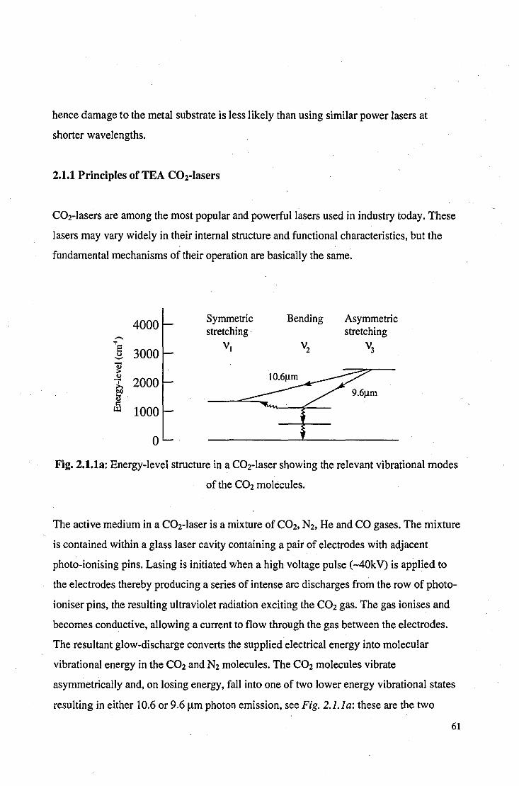
hence damage to the metal substrate is less likely than using similar power lasers at
shorter wavelengths.
2.1.1 Principles of TEA COrlasers
CO2-lasers are among the most popular and powerful lasers used in industry today. These
lasers may vary widely in their internal structure and functional characteristics, but the
fundamental mechanisms of their operation are basically the same.
4000 Symmetric Bending Asymmetric
~
stretching stretching "8
3000 VI V2 V3
" ~ 11 ..,
2000 0' >. e.o 1J Ul 1000
0
Fig. 2.1.1a: Energy-level structure in a CO2-laser showing the relevant vibrational modes
ofthe CO2 molecules.
The active medium in a COr laser is a mixture of C02, N2, He and CO gases. The mixture
is contained within a glass laser cavity containing a pair of electrodes with adjacent
photo-ionising pins. Lasing is initiated when a high voltage pulse (-40kV) is applied to
the electrodes thereby producing a series of intense arc discharges from the row of photo
ioniser pins, the resulting ultraviolet radiation exciting the CO2 gas. The gas ionises and
becomes conductive, allowing a current to flow through the gas between the electrodes.
The resultant glow-discharge converts the supplied electrical energy into molecular
vibrational energy in the C02 and N2 molecules. The C02 molecules vibrate
asymmetrically and, on losing energy, fall into one of two lower energy vibrational states
resulting in either 10.6 or 9.6 /lm photon emission, see Fig. 2.1.1a: these are the two
61

principal vibrational transitions of the CO2-laser. The excited N2 molecules excite other
C02 molecules to the upper laser level.
Collisions with the helium gas aid the C02 molecules which have 'Iased' to drop down
from the lower energy levels to the ground state to sustain the population inversion
required for lasing. Mirrors at either end of the cavity define the directional characteristics
of the radiation and ensure that the infrared radiation is directed along the cavity and out
through the partially reflecting mirror. Rows of fans built into the laser cavity allow for
high repetition rates by ensuring that the gas between the electrodes is changed after each
discharge.
CO is present in the laser mix to neutralise any 'free oxygen' produced by the breakdown
of the C02 by the electrical discharge: a constant supply of fresh gas is required to
replenish gas lost through breakdown. Temperatures inside the cavity must be kept below
about 420K to maintain high gain levels so an internal water-cooled heat exchanger cools
the gas as it circulates. Temperatures in excess of 420K cause significant population of
the lower laser levels and hence reduce the gain of the laser cavity.
TEA CO2-lasers, such as the one used in the experiments described in this thesis, differ
from other C02-lasers by passing electric pulses through the gas in a direction transverse
to the laser cavity axis. This arrangement produces pulsed as opposed to continuous wave
radiation, and enables the laser to operate at much higher cavity pressures and extremely
high powers per unit volume of gas compared with alternative arrangements[18].
2.1.2 Laser interactions with materials
Laser ablation
Any explosive laser-material interaction is generically termed 'laser ablation,[19]. The
conditions that are required for ablation vary considerably, but typically require
62

microsecond (or shorter) pulses with irradiances in excess of I09Wlcm2 focused onto a
sufficiently absorbing material, as shown in Fig. 2.1.2a. The vaporisation temperature of
the surface is exceeded within a fraction of the pulse duration. The vaporised (blow-oft)
material has insufficient velocity to escape the surface before the underlying material is
vaporised. Hence, temperature and pressure at the surface are rapidly increased to cause
an explosion, an observable plasma or plume, and audible report. The rate of vaporisation
can be so rapid that insufficient time is permitted for the significant transfer of heat into
the bulk of the material by conduction, hence evidence of melting is often absent from the
ablation site.
Hot plume/plasma
Target
Transport lens medium
Fig. 2.1.2a: TEA C02-laser ablation of target material. The transport medium is usually
air.
Ablation mechanisms
Depending on the wavelength of the incident radiation, one of two interaction processes
are likely to dominate[201.
Photochemical absorption: this dominates short wavelength (i.e. ultraviolet) interactions
with matter. Incident photons induce electronic transitions to higher energy states within
the target material. Transitions can lead to molecular dissociation by attaining an energy
level above the dissociation limit or by creating an energy state that is sufficiently
repulsive. Photochemical absorption of a single photon will usually be sufficient to cause
dissociation in a given molecule.
63

Thermal absorption: individual visible and infrared photons do not usually have sufficient
energy to break chemical bonds. Visible and infrared radiation is absorbed into the
vibrational modes of the molecules directly or indirectly, via low-lying electronic energy
states. These thermal processes raise the temperature of the target material and cause
dissociation through vaporisation. Multiple photon absorption can also cause dissociation
through photochemical processes, although this is unlikely due to the short lifetimes of
low-lying energy states.
2.1.3 Factors affecting ablation characteristics
Laser characteristics
In many respects, it is difficult to alter the parameters of pulsed radiation for most lasers.
A TEA CO2-laser has ~o method of altering pulse duration or wavelength without great
financial expenditure and loss of power. Apart from angle of incidence and laser fluence
(controlled using a simple lens), all other laser parameters are essentially fixed.
Wavelength: determines to what extent ablation is likely to be a photochemical or thermal
process. TEA CO2-lasers emit at IO.6J.lm, in the far infrared, so the majority of the
interaction is likely to be thermal.
Radiant flux density or RFD (power/area) : in general, only pulsed lasers are powerful
enough to deliver sufficient energy to a surface rapidly enough to prevent significant
conduction to the bulk material, thereby ensuring a well-defined thermal discontinuity.
The RFD can easily be varied using a simple convex lens to alter the spot dimensions.
The rate of energy transfer to the surface is directly related to the RFD if interaction with
the blow-off material is ignored. At an RFD high enough to exceed the plasma threshold
for a given material, the blow-off material may absorb sufficient radiation to become
ionised and form an opaque plasma, effectively shielding the target from the remaining
laser pulse. Thus, the most efficient cleaning RFD is usually just below the plasma
64

threshold; using a lower RFD would expend a greater proportion of energy heating, but
not vaporising, the target material.
Pulse duration: is a fixed parameter for many pulsed lasers and may vary from
microseconds down to picoseconds for different lasers. A short pulse duration reduces the
likelihood of thermal conduction between ablating material and the underlying material.
Angle of incidence: The reflectivity of materials is a function of the angle of the incident
radiation. However, corroded surfaces have a surface roughness that presents a randomly
orientated profile to the laser such that the angle of incident varies across the sample.
Spatial beam profile: all lasers exhibit intensity variation across the spatial profile of the
beam. Intensity variations are caused by stable configurations of electromagnetic field
within the resonant cavity, called modes, and diffraction effects at the aperture. The TEA
C02-laser used in these experiments operated in multi mode emission: this extracts the
most output power from the laser cavity but produces an uneven beam with large
divergence, see Fig 2.1.3a. Beam inhomogeniety will produce variation in the rate of
ablation across the irradiated target area, and 'hot-spots' may induce undesirable plasma . . ignition. Beam homogenisers are available but are limited in their power handling
capabilities. In general, however, when lasers are used for surface processing
applications, high power beam delivery takes precedence over beam quality.
Fig. 2.1.3a: TEA CO2-laser pulse incident on thermosensitive paper (actual size). The
different modes are visible as horizontal lines.
65

Temporal beam profile (TBP): pulsed lasers do not deliver energy at a constant rate but
have a characteristic.pulse profile typically consisting of a pronounced peak with a
relatively long tail, see Fig 2.1.4c. The laser flux is thus varying throughout the duration
of each pulse and only approaches the maximum for a fraction of the overall pulse length.
Target characteristics
Although target characteristics are fundamental in determining laser-material interactions,
many of the properties of the target will vary during the ablation process adding dynamic
complexity to the system.
Reflectivity (R): determines what proportion of incident radiation is absorbed by the
target and how much is reflected from the sample. Radiation incident on highly reflective
samples may still form a plasma if the flux is sufficiently high to ionise the transport
medium. The reflectivity of metals decreases as an approximately linear function of
increasing temperature, as determined by the Drude model[21]. The absorptivity (I-R) may
as much as double from a temperature increase of a few hundred degrees or with a change
of state from solid to liquid, for example, the absorptivity of pure silver increases from
0.0197 to 0.0374 on melting[22J.
Absorption coefficient (a): once radiation has penetrated the target, the heating effect that
follows is dependent upon the rate of absorption. Metals typically have an absorption
coefficient in the region of 106cm-l for 1O.61lm radiation and, although this results in the
rapid absorption of radiation close to the surface, their high reflectivities at this
wavelength significantly reduce any heating effects, see Fig. 2.4.1 a.
Meltinglboiling point and latent heat of fusion/vaporisation: determine whether the
energy coupled with the target is sufficient to cause a change in state.
66
Thermal conductivity (K) and diffusivity (K): a highly conducting target provides a heat
sink for the energy coupled to the surface thus reducing the surface temperature. For most
metals, thermal conductivity and diffusivity decrease as an approximately linear function
of temperature increase; brass and bronze are an exception as their thermal conductivities
and diffusivities increase as a function of temperature.
Thickness: After each laser pulse is delivered to the target the heat energy is dissipated
from the surface to the bulk of the sample and is gradually re-radiated into the
surrounding atmosphere. Thus, successive pulses will gradually increase the temperature
of the bulk material until there is eqUilibrium between the supplied and dissipated energy.
The bulk temperature rise per pulse is therefore dependent on the thickness of the target
for a given substrate.
Transport medium characteristics
Although the most convenient transport medium for laser cleaning is air, directing a flow
of alternative gas[23.24J or applying a liquid coating to the target[25J can significantly alter
the laser/surface interaction.
Density: a dense (Le. solid or liquid), transparent medium that allows the laser beam to
penetrate to the surface can accelerate the cleaning process. For example, if a thin layer of
water is applied during the removal of a black crust from limestone, the laser heated crust
causes an explosi ve vaporisation of the water which exerts sufficiently large forces on the
underlying crust to loosen and eject material from it[26J.
Ionisation energy: the ionisation energy of a gaseous transport medium can provide
control over the breakdown threshold for plasma formation during laser treatment.
However, if a significant mass of blow-off material is produced during the treatment
process, a plasma may form from the ablation products regardless of the type of gaseous
environment employed.
67

Reactivity: will determine whether, and to what extent, there will be a chemical reaction
between the transport medium and the surface of the target material. For example, the use
of an inert gas transport medium will prevent the surface reacting with the atmosphere
during laser-treatment. Metal surfaces may oxidise if heated by a laser in an oxygen or air
atmosphere.
2.1.4 Plasma/sub'plasma cleaning effects
By varying the flux incident on a given target, the blow-off material may take one of three
forms:
(i) Plume: a gaseous emission of vaporised material that may be accompanied by solid
particulate matter in the form of smoke. At infrared wavelengths the plume has a very low
absorption coefficient and will not significantly deprive the surface of subsequent
radiation. No visible light is emitted by the plume although an audible 'click' may be
produced by the rapid expansion of gas.
(ii) Hot-plume: at a higher flux, the blow-off material may absorb sufficient radiation to
emit a characteristic orange/yellow glow, see Photo 2.1.4a. Some of the blow-off material
may be ionised and increase the absorPtivity of the plume to the laser radiation. Each
pulse creates a loud snap.
(iii) Plasma: a plasma is a dense cloud of interacting ionised gas the formation of which
requires a very high flux; The plasma may be produced from the transport medium (e.g.
air-breakdown), the blow-off material from the target, or both, and appears as a bright
blue spark, see Photo 2.1.4h, accompanied by a very loud acoustic shock. Due to the high
absorptivity of the plasma, further exposure of the target surface to laser radiation is
prevented for its duration.
68

Plasma formation
The radiation intensity that is required to initiate plasma formation is known as the
plasma threshold (typically of the order of 101lWcm·2 for gas breakdown[25J). The
initiation of plasma formation by C02-lasers is not fully understood - the ionisation
potential of many gases far exceeds the quantum energy of the laser. A possible
mechanism of initiation may be by the process of multi-photon ionisation whereby the
simultaneous absorption of many quanta by a single atom can produce an ion-electron
pair. The presence of impurities, such as dust, in the transport medium can significantly
lower the plasma threshold for that medium by providing sites of high absorption. Once
ionisation is initiated, the free electrons absorb photons through the inverse
brehmsstrahlung process in which individual photons are absorbed by an electron in the
field of a heavy particle (e.g. atom or ion). The inverse brehmsstrahlung process is
proportional to the laser wavelength squared and is therefore relatively large for CO2-
lasers[19J. As these electrons gain energy they can ionise more atoms through collisions,
multiplying the ionised species and the process cascades to form a body of ionised species
that is the plasma.
Plasma effects
The plasma forms an opaque, absorptive and impenetrable barrier to the laser for the
subsequent duration of the pulse and therefore has a shielding effect. The target surface,
however, will become irradiated by the plasma itself. The spectra of plasma radiation will
appear as a Plancks' curve superposed with discrete peaks at the ionisation potentials of
the various incorporated ionised species, as shown in Fig 2.4.2b. Plasma radiation can
cover the infrared, visible, ultraviolet and soft X-ray regions of the spectrum. The surface
of a target may be absorptive of plasma radiation although reflective of the laser radiation
and significant surface heating may ensue. Ionised species may also be incident on the
surface of the sample producing chemical interactions such as oxidation.
69
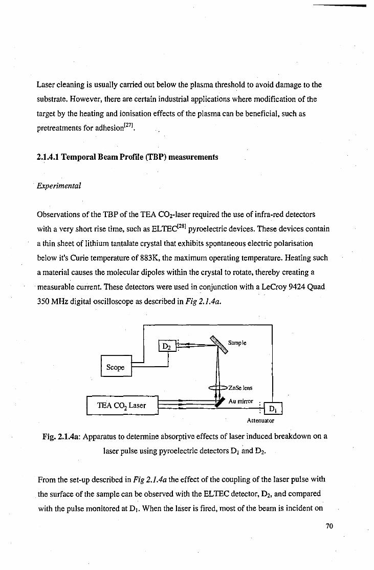
Laser cleaning is usually carried out below the plasma threshold to avoid damage to the
substrate. However, there are certain industrial applications where modification of the
target by the heating and ionisation effects of the plasma can be beneficial. such as
pretreatments for adhesion[27].
2.1.4.1 Temporal Beam Profile (TBP) measurements
Experimental
Observations of the TBP of the TEA CO2-laser required the use of infra-red detectors
with a very short rise time, such as ELTEC[28] pyroelectric devices. These devices contain
a thin sheet of lithium tantalate crystal that exhibits spontaneous electric polarisation
below it's Curie temperature of 883K, the maximum operating temperature. Heating such
a material causes the molecular dipoles within the crystal to rotate, thereby creating a
. measurable current. These detectors were used in conjunction with a LeCroy 9424 Quad
350 MHz digital oscilloscope as described in Fig 2.1.4a.
Sample
Scope
CIDZnSe lens
TEA CO2 Laser Au mirror
Attenuator
Fig. 2.1.4a: Apparatus to determine absorptive effects of laser induced breakdown on a
laser pulse using pyroelectric detectors Dj and D2.
From the set-up described in Fig 2.1.4a the effect of the coupling of the laser pulse with
the surface ofthe sample can be observed with the ELTEC detector, D2, and compared
with the pulse monitored at DI. When the laser is fired, most of the beam is incident on
70
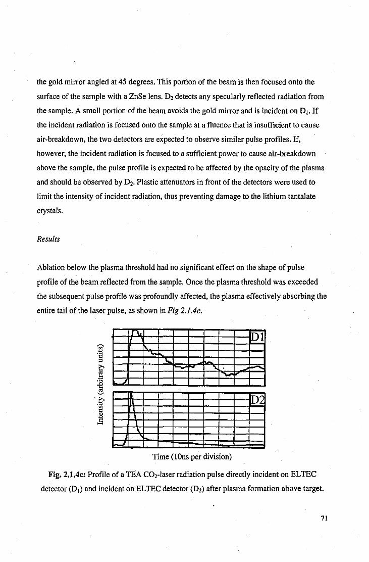
the gold mirror angled at 45 degrees. This portion of the beam is then focused onto the
surface of the sample with a ZnSe lens. 02 detects any specularly reflected radiation from
the sample. A small portion of the beam avoids the gold mirror and is incident on 01. If
the incident radiation is focused onto the sample at a f1uence that is insufficient to cause
air-breakdown, the two detectors are expected to observe similar pulse profiles. If,
however, the incident radiation is focused to a sufficient power to cause air-breakdown
above the sample, the pulse profile is expected to be affected by the opacity of the plasma
and should be observed by 02. Plastic attenuators in front of the detectors were used to
limit the intensity of incident radiation, thus preventing damage to the lithium tan tal ate
crystals.
Results
Ablation below the plasma threshold had no significant effect on the shape of pulse
profile of the beam reflected from the sample. Once the plasma threshold was exceeded
the subsequent pulse profile was profoundly affected, the plasma effectively absorbing the
entire tail of the laser pulse, as shown in Fig 2.1.4c.
-\, 1!21 ... ... '-
." ,....
102
\
J
Time (IOns per division)
Fig. 2.1.4c: Profile of a TEA COz-Iaser radiation pulse directly incident on ELTEC
detector (01) and incident on ELTEC detector (02) after plasma formation above target.
71
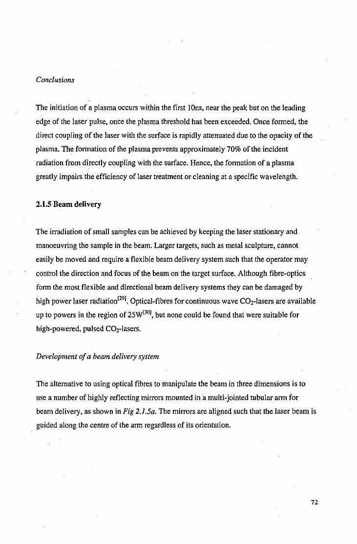
Conclusions
The initiation of a plasma occurs within the first IOns, near the peak but on the leading
edge of the laser pulse, once the plasma threshold has been exceeded. Once formed, the
direct coupling of the laser with the surface is rapidly attenuated due to the opacity of the
plasma. The formation of the plasma prevents approximately 70% of the incident
radiation from directly coupling with the surface. Hence, the formation of a plasma
greatly impairs the efficiency of laser treatment or cleaning at a specific wavelength.
2.1.5 Beam delivery
The irradiation of small samples can be achieved by keeping the laser stationary and
manoeuvring the sample in the beam. Larger targets, such as metal sculpture, cannot
easily be moved and require a flexible beam delivery system such that the operator may
control the direction and focus of the beam on the target surface. Although fibre-optics
form the most flexible and directional beam delivery systems they can be damaged by
high power laser radiation[29l. Optical-fibres for continuous wave CO2-lasers are available
up to powers in the region of 25W[30l, but none could be found that were suitable for
high-powered, pulsed COr lasers.
Development of a beam delivery system
The alternative to using optical fibres to manipulate the beam in three dimensions is to
use a number of highly reflecting mirrors mounted ina multi-jointed tubular arm for
beam delivery, as shown in Fig 2.1.5a. The mirrors are aligned such that the laser beam is
guided along the centre of the arm regardless of its orientation.
72
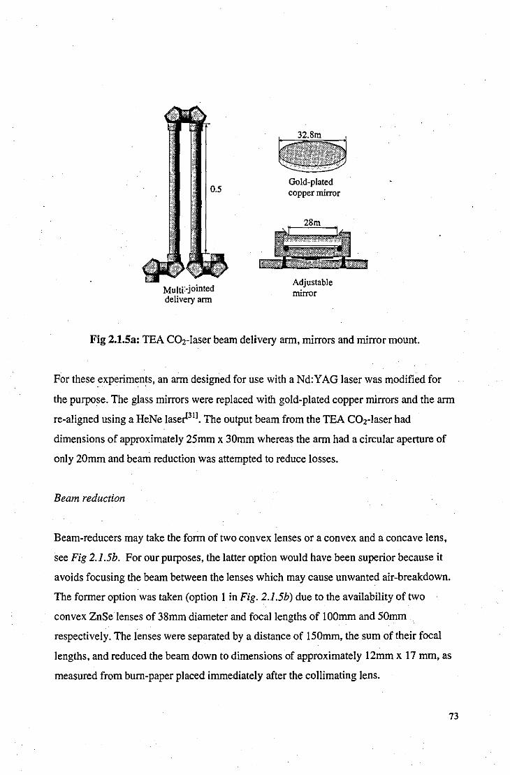
Multi:-jointed delivery arm
Gold-plated copper mirror
Adjustable mirror
Fig 2.t.Sa: TEA CO2-laser beam delivery arm, mirrors and mirror mount.
For these experiments, an arm designed for use with a Nd:YAG laser was modified for
the purpose. The glass mirrors were replaced with gold-plated copper mirrors and the arm
re-aligned using a HeNe laser[3I]. The output beam from the TEA CO2-laser had
dimensions of approximately 25mm x 30mm whereas the arm had a circular aperture of
only 20mm and beam reduction was attempted to reduce losses.
Beam reduction
Beam-reducers may take the form of two convex lenses or a convex and a concave lens,
see Fig 2.1.5b. For our purposes, the latter option would have been superior because it
avoids focusing the beam between the lenses which may cause unwanted air-breakdown.
The former option was taken (option 1 in Fig. 2.1.5b) due to the availability of two
convex ZnSe lenses of 38mm diameter and focal lengths of IOOmm and 50mm
respectively. The lenses were separated by a distance of l50mm, the sum of their focal
lengths, and reduced the beam down to dimensions of approximately l2mm x 17 mm, as
measured from bum-paper placed immediately after the collimating lens.
73
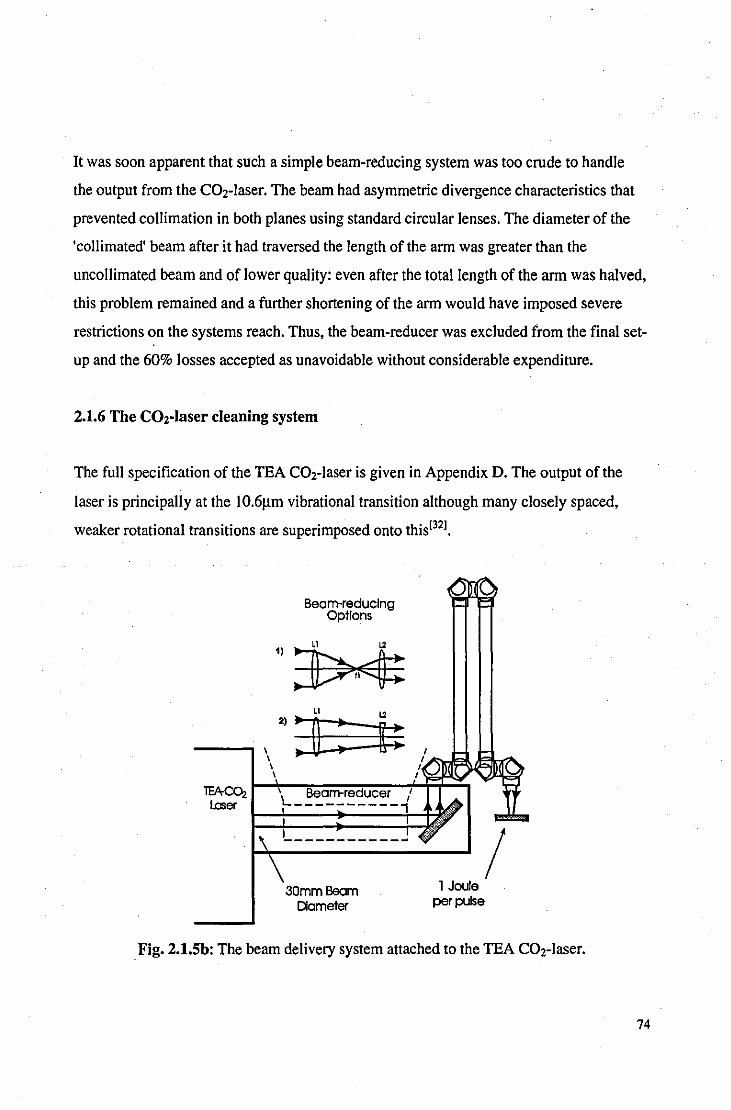
It was soon apparent that such a simple beam-reducing system was too crude to handle
the output from the CO2-laser. The beam had asymmetric divergence characteristics that
prevented coIlimation in both planes using standard circular lenses. The diameter of the
'collimated' beam after it had traversed the length of the arm was greater than the
uncoIlimated beam and of lower quality: even after the total length of the arm was halved,
this problem remained and a further shortening of the arm would have imposed severe
restrictions on the systems reach. Thus, the beam-reducer was excluded from the final set
up and the 60% losses accepted as unavoidable without considerable expenditure.
2.1.6 The C02-laser cleaning system
The fuIl specification of the TEA C02-laser is given in Appendix D. The output of the
laser is principaIly at the IO.6~m vibrational transition although many closely spaced,
weaker rotational transitions are superimposed onto this[321.
lEACOz Laser
Beam-reducing Options
1):t>f~ 1.2
L __________ _
30mmBeam Diameter
1 Joule per pulse
/ . Fig. 2.1.Sb: The beam delivery system attached to the TEA C02-laser.
74

The laser operates in multi mode emission which optimises the total energy output from
the laser cavity at the expense of beam quality (e.g. rapid divergence, large diameter and
uneven intensity). The modified beam-delivery arm, as shown in Fig 2.1.5b, was mounted
to the front of the laser when targets exceeded a convenient size for manipulation in the
fixed beam. A very thin clear polyethylene sheet served as a guard against blow-off
material damaging the delicate ZnSe lens.
2.2 Surface chemistry analysis
As described in Chapter 1, the chemistry of corrosion products determines~ to a large
extent, their quality and desirability on metal objects. A wide. variety of methods of
surface chemical analysis are available, each offering certain advantages and
disadvantages over alternative methods. This section describes some of the methods used
to obtain the results presented in Chapter 3, X-ray powder diffraction analysis was the
most favoured analytical technique and shall be described in greater depth than the
alternative methods.
2.2.1 X-ray powder diffraction analysis (XRD)
Principles of operation
The regular arrangement of atoms in a crystal lattice form sets of crystal planes. For a
given wavelength (A.), the condition for simultaneous constructive interference for a beam
of X-rays reflected from each horizontal plane is given by the Bragg equation,
nA. = 2dsin8 Eqn 2.1
where d is the lattice spacing, n is an integer and 8 is the incident angle measured from
the crystal surface. Thus, from recording the angle of diffracted radiation from a single
75
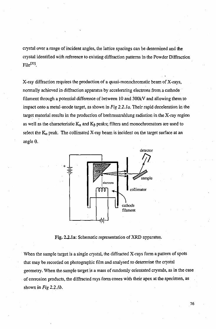
crystal over a range of incident angles, the lattice spacings can be detemiined and the
crystal identified with reference to existing diffraction patterns in the Powder Diffraction
File[331.
X-ray diffraction requires the production of a quasi-monochromatic beam of X-rays,
normally achieved in diffraction apparatus by accelerating electrons from a cathode
filament through a potential difference of between 10 and 300k V and allowing them to
impact onto a metal-anode target, as shown in Fig 2.2.1a. Their rapid deceleration in the
target material results in the production of brehmsstrahlung radiation in the X -ray region
as well as the characteristic Ka and K~ peaks; filters and monochromators are used to
select the K" peak. The collimated X-ray beam is incident on the target surface at an
angle 8.
+
collimator
filament
Fig. 2.2.1a: Schematic representation of XRD apparatus.
When the sample target is a single crystal, the diffracted X-rays form a pattern of spots
that may be recorded on photographic film and analysed to determine the crystal
geometry. When the. sample target is a mass of randomly orientated crystals, as in the case
of corrosion products, the diffracted rays form cones with their apex at the specimen, as
shown in Fig 2.2.1h.
76

x-ray beam
diffralion
..... .....
Fig: 2.2.1b: Diffraction ring fonned by randomly orientated crystal powder.
As the powder sample is rotated at increments of 0.02 degrees, the detector, housed in a
goniometer that rotates with the sample at an angle of 20 (with respect to the incident
beam of X-rays), records the intensity of the diffracted radiation. Strong diffraction peaks
are superimposed on background radiation to gi ve a diffraction pattern over a prescribed
range of angles, as shown in Fig 2.2.1c.
30000
25000
20000
~ .. 15000 c ., :s
10000
5000 11 1.t J . 1. ..... 0
0 0 g 0 0 g R 0 ~ '"
..,. '"
., Angle (2 Theta)
Fig: 2.2.1c: Diffraction peaks from a powder scan of corrosion products.
Eqn 2.1 can be used to find the d-spacing of the lattice planes corresponding to each
diffraction peak. Identification of the sample material can then be made by comparing the
d-spacing and relative peak intensities with those of known compounds.
77
Attributes ofXRD
Compound identification: XRD provides more than just elemental analysis and can
provide the full chemical formula for any of the tens of thousands of compounds already
recorded. Compounds are identified by matching the strongest diffraction peaks with
those listed in the powder diffraction reference catalogues. This method of analysis also
allows for different phases of metals, alloys and inorganic compounds to be distinguished.
Even compounds with the same chemical formula but different structures, such as PbO
(litharge) and PbO (massicot), can be distinguished. When a variety of compounds are
present on a sample this process becomes an arduous task as it is not often clear which
peaks belong together. To take the tedium out of the process, a simple data-base was
created to include the three most significant peaks of all the corresponding compounds
recorded in the Powder Diffraction Files. XRD can only identify compounds that have a
crystalline structure and therefore can be used on almost all inorganic compounds but few
organic compounds. Completely amorphous compounds cannot be identified using XRD.
Proportions of components: semi-quantitative chemical analysis can be provided by the
relative intensities of the diffraction peaks of respective compounds. Diffraction peak
intensities for a given compound are not only a function of quantity, however, but also
vary significantly with factors such as the size of crystallites and dimensions of the
Bravais lattice' . Even if the results are properly calibrated the accuracy of quantitative
analysis is generally poor.
Volume of analysis: the area of the target irradiated by the X-rays typically covers a few
square millimeters which is sufficient to include all the compounds present. The X-rays
have sufficient energy to penetrate through corrosion layers to the metal substrate, thereby
providing information on the whole corrosive system and also the metal substrate .
• The Bravais lattice is an indefinitely repetitive arrangement of points in space that fulfils the condition that the environment of each point is identical to that of every other point. There are fourteen such arrangements in regular crystal systems.
78
Sensitivity: the intensity of diffracted peaks is proportional to the number of planes
presented to the incident X-rays. Too few crystallites (i.e. too thin a corrosion layer) or
crystallites too small to produce sufficient constructive interference may give poor peaks
that will be lost in the background noise of the device. Also, corrosion layers containing
large crystallites (i.e. in excess of Il1m) may produce a non-uniform diffraction cone and
peaks will escape detection if the goniometer travels through a particularly weak section
ofthe cone. The sensitivity will also vary depending on how effectively the structure of
the compound under analysis diffracts X-rays. In general, most corrosion layers could be
analysed satisfactorily and were typically a few tens of microns in thickness. The
sensitivity of the instrument could be increased by increasing the scan duration or the
number of passes for more difficult samples. In this way, any background noise caused by
scattered X-rays could be reduced relative to the signal.
Errors: the accuracy to which each peak is resolved is determined by setting the angular
increment on each scan. Although this increment remains constant, the d-spacing is
proportional to the reciprocal of the sine of the diffraction angle (see Eqn 2.1) and, for a
typical scan from 10 to 90 degrees, the interval of the d-spacing decreases as the angle
increases. This was taken into account when identifying peaks by comparison with the d
spacings listed in the diffraction files: a closer match was expected as the diffraction
angle increased. Low-order lines are also displaced by absorption of X-rays in the
specimen to create irregular peaks. Not all diffraction patterns are unique and there are
some cases where multiplicity could cause difficulties in the identification of the target
material. Most minerals have complex, low-symmetry diffraction patterns which are
unique to that compound but some metals and alloys produce identical diffraction
patterns. Atomic replacements within the same structure are very common in minerals
which results in considerable variation in the positions and relative intensities of their
diffraction patterns.
79

2.2.2 X-ray photoelectron spectroscopy (XPS)
Principles of operation
X-ray source
Electron ~_ analyser ( n '\
Sample
IiI Electron .. detector
Probe To pumps
Fig: 2.2.2a: Schematic representation of XPS apparatus.
XPS uses a monochromatic beam of X-rays of known energy to eject photoelectrons from
the target probe into an electron analyser, as shown in Fig 2.2.2a. Assuming a negligible
recoil energy from the emitting atom, the kinetic energy (Ek) of the photoelectron is equal
to the energy of the X-ray (hv) minus the binding energy (Eb) of the atom, see Eqn 2.2.
The electron detector is able to detennine the energy of the photoelectrons from which the
binding energy can be found and the element identified.
Ek = hv - Eb Eqn 2.2
Thus, every band in an XPS spectrum corresponds to an occupied atomic or molecular
orbital ofthe sample substance. This provides not only elemental analysis, but also
information on the oxidation states of the target compounds.
80

Attributes ofXPS
Compound identification: XPS can provide elemental analysis of all solids, organic and
'inorganic, although it will not detect hydrogen or helium. The oxidation states of
elements can also be determined which provides some indication as to the structure of the
compounds.
Proportions of constituents: the atomic percentage of elements present can be provided to
an accuracy of up to 0.1 %.
Sampling depth: depending on the energy of the incident X-rays (typically below 1200eV)
and the properties of the target material, the sampling depth can vary between 2 and
10nm. It is very likely that the top 10nm of a corrosion layer does not accurately represent
the bulk of the corrosion layer, and XPS analysis was generally reserved for studying very
thin corrosion layers or homogenous paint layers. Depth-profiling using ion
bombardment is possible on some XPS apparatus but was not available on our machine.
Errors: The sampling depth makes XPS very sensitive to surface contamination, such as
dust or finger-prints, and samples were wrapped in aluminium foil between treatment and
XPS analysis, which was carried out as soon as possible after treatment was completed.
, 2.2.3 Auger electron spectroscopy (AES)
Principles of operation
AES differs from XPS in that it uses a focused, mono-energetic electron beam to
bombard the surface of the target material. The energy of. the incident electrons are
typically in the order of a few ke V and can be sufficiently energetic to dislodge a core
level electron as a secondary electron thereby leaving a vacancy in the electron shell. One
of the methods by which this excited atom can relax is via the Auger process which
81

results in another (Auger) electron being emitted from the surface. The energy of the
Auger electron depends only upon the electron energy levels of the states involved in the
Auger process and are quite independent of the energy of the impacting species (in
contrast to XPS). The energy of the incident electrons is determined by a compromise
between good spatial resolution (high beam energy, e.g. I Oke V) and low beam damage
(low beam energy, typically IkeV) with a minimum of 3keV required to excite all the
atomic species that may be present. AES is performed in a near-vacuum (between 2* 10.8
and 2* 10.9 TOff) environment to minimise electron scatter and recontamination of the
target; even at pressures as low as 10.6 TOff a monolayer of oxygen is laid down within
1.5 seconds[341.
Attributes of AES
Compound identification: AES is particularly useful for studying compounds containing
light atoms (Le. 2<13) because for these the ejection of Auger electrons is the major
relaxation process for the induced excited states. Although AES can be used on all
inorganic compounds and metals, it cannot give information on organic compounds due
to surface charging effects ofthe incident electrons. As with XPS, hydrogen and helium
cannot be detected by AES.
Proportions of components: the atomic percentage of elements present can be provided to
an accuracy of up to 0.1 %.
Sampling depth: depending on the energy of the incident electrons (typically between
IkeVand IOkeV) and the properties of the target material, the sampling depth can vary
between 2 and IOnm. Depth-profiling using argon ion-bombardment was available to us
although this process requires calibration with a similar sample of known thickness. Such
samples were not normally available and therefore this technique could not easily be
applied.
82

Errors: As with XPS, sampling depth makes AES very sensitive to surface contamination,
such as dust or finger-prints, and samples were protected from the atmosphere between
treatment and AES analysis.
2.2.4 Contact angles
The careful placement of a drop of liquid on a solid surface can elucidate considerable
information as to the nature of the surface simply by measuring the angle which the
boundary of the droplet makes with the surface. This angle, known as the 'contact angle',
is determined by the mechanical equilibrium ofthe three surface tensions (Le. free energy
per centimetre square) Ysh at the interface of the solid and the liquid, /lv, at the interface of
the liquid and the vapour, and Ysv at the interface of the solid and the vapour, as shown in
Fig 2.2.4a.
Vapour ~Y , Iv \
Fig. 2.2.4a: Contact angle (9) of a water droplet.
When in equilibrium, these three parameters are related by Eqn 2.Jf351•
Ysv • YsI = /lv cos a Eqn2.3
Thus, the contact angle is a function of the surface parameters of the solid and is
independent of the volume of the drop for a homogenous, flat, solid surface. The surface
free energy of a solid increases with its melting point and hardness. Metals, oxides, and
mineral compounds have high specific surface energies typically between 0.5 and 5 J/m2•
Most organic compounds are soft, with low melting points, and have low specific surface
83

energies below 0.1 11m2• Hence, organic liquids are generally found to spread freely on
solids of high surface energy, since this results in a large decrease in the surface energy of
the system.
Measurement of contact angle
A simple method of measuring contact angles was to produce a magnified image of the
droplet using the apparatus shown in Fig 2.2.4b.
Light Source
Water droplet
Projectorlens system
Screen
Fig. 2.2.4b: 'In-house' projector designed for the measurement of contact angles.
The image on the screen was marked out by placing a cross at the upper-most point on the
droplet boundary and at the two points where the droplet came into contact with the
surface. The ratio of the height (h) and diameter (d) of the water droplet was measured,
from which the contact angle could be calculated using Eqn 2.4 (see Appendix G).
Tan 9/2 = 2h1d Eqn2.4
Uses of contact angles
Although detailed chemical and topographical information can be obtained from contact
angles, this requires specialised equipment and techniques. Contact angles were of most
84

use in laser cleaning as a rapid test for the presence of organic contamination on the metal
surface. A metal surface that was completely free of organic compounds would show zero
contact angle although even the presence of an adsorbed monolayer of organic
contamination produces a finite contact angle[361•
2.3 Surface topographical analysis
2.3.1 Colour photography
Colour photography is a simple and accurate method of recording the visible effects of
the laser-cleaning on surface topography. The set-up used incorporated a Pentax ME
Super SLR camera with a 50mm lens and flash, as shown in Fig 2.3.1 a. Extension tubes
were used for macro-photographs and a diffuse reflector softened the effect of the flash.
Diffuse reflector
Extension tubes
Stand
Fig. 2.3.1a: Macro-photography experimental set-up
Kodak 'Gold' film was used of l00ASA or 200ASA. Photographs were taken before,
during and after cleaning. Colour photographs are displayed at the end of Chapter 3.
2.3.2 Embedded cross-section
To obtain photographs of cross-sections taken through samples they must first be
embedded in a resin. The corrosion layers are thin and friable and require the support of a
85

surrounding resin to prevent them being damaged whilst the sample is being ground and
polished.
Paper-clip
Mould
Sample
Fig. 2.3.2a: Embedding apparatus for cross-section analysis
The samples are attached to paper-clips prior to the introduction of the resin to enable
positioning, as shown in Fig 2.3.2a. If the surface of the sample is angled slightly to the
base of the resin mould a tapered cross-section can be obtained that extends its profile and
presents a larger surface area to be photographed.
Once the resin has set the mould can be removed. The sample is then sanded down with
consistently higher grades of silicon carbide paper until a 1000 grade finish has been
obtained. The sample is then polished using a soft cloth impregnated with a high-quality
metallurgical polish, or using an automated polishing machine with diamond paste,
depending on the required finish. Etching may also be performed on the cross-section to
provide detail of the grain structure of the metal, the etch ant used being dependent upon
the type of metal or alloyl371. The cross-section is viewed with a metallurgical microscope
with a camera attachment. Photographs are taken with indoor film to compensate for the
colour of the tungsten-filament lamp lighting.
Types of resin
There are various types of cold setting mounting resins commercially available, such as
polyester, acrylic and epoxy resins. A suitable resin provides good edge protection with
low shrinkage characteristics. 'Epofix' mounting resin was used for our studies because its
low viscosity allows for impregnation of the porous corrosion layers thus consolidating
any friable material and improving edge protection. 86

2.3.3 Scanning Electron Microscopy (SEM)
By using electrons, with de Broglie wavelengths of 0.05 angstroms or less, instead of
visible light, the SEM can achieve far greater resolution than any optical microscope due
to the greatly reduced diffraction effects. The linear resolution of electron microscopy is
limited by lens aberrations and by scattering within the specimen, but is typically of the
order of 5 to 10 angstroms, compared with the 2000 angstroms of the best optical
microscopes.
The SEM is a valuable tool for detailed topographical analysis but will, of course,
produce only black and white as opposed to colour pictures. SEM micrographs of laser
treated metals are displayed at the end of Chapter 4.
2.4 In-line laser observations
The surface analysis procedures outlined in sections 2.2 and 2.3 are all limited in that they
require a significant time for processing and sample preparation that confines their use to
analysis after the laser cleaning/processing has been completed. Such methods provide
accurate and useful information but do not give direct feedback to the laser operator as to
the state and condition ofthe target. The methods outlined in this section provide the
operator with pulse-by-pulse information as to changes occurring in the system during
ablation.
2.4.1 Surface temperature measurement
For an opaque material, such as a metal (et = 105 to 106 cm· l) the temperature/depth
profile resulting from a laser pulse (assuming no change in state) may be approximated to
the following[38J
87

~T(z,t) = (2I(1-R)/K)(Kt)"2. ierfc[zl2(Kt) 112] Eqn 2.5
where ~ T is the terriperature increase, I the intensity of the incident radiation, R the
reflectivity of the target surface, K the thermal conductivity of the target material, K the
thermal diffusivity of the target, z is depth, t is time and ierfc is the complex error
function. This equation assumes that re-radiation from the heated surface is negligible (it
is typically less than 1%); that the duration of the pulse is of the order of IOns or longer;
that the thermal properties of the target material are independent of temperature and,
although this is obviously not true for metals, that the thermal properties do not vary
greatly over wide temperature ranges. Utilising this equation illustrates the rapid
attenuation of the temperature as the bulk of the sample is approached, as shown in Fig
2.4.1 a; almost all of the heat energy is contained within the top IOJlm of the target
material after the duration of a single pulse.
Te~t------------------------,
o 0.00002 Z(m)
0.00004
Fig. 2.4.1a: Theoretical temperature-rise/depth profile of steel immediately after a 2J,
lOOns, square 10.6 Jlm laser pulse is incident on Icm2 of surface.
To calculate the theoretical temperature rise at the surface of the sample, Eqn 2.5 can be
simplified to Eqn 2.6 by substituting z=O,
~T = (2I(1-R)/K)(K tl1t)1/2 Eqn 2.6
88
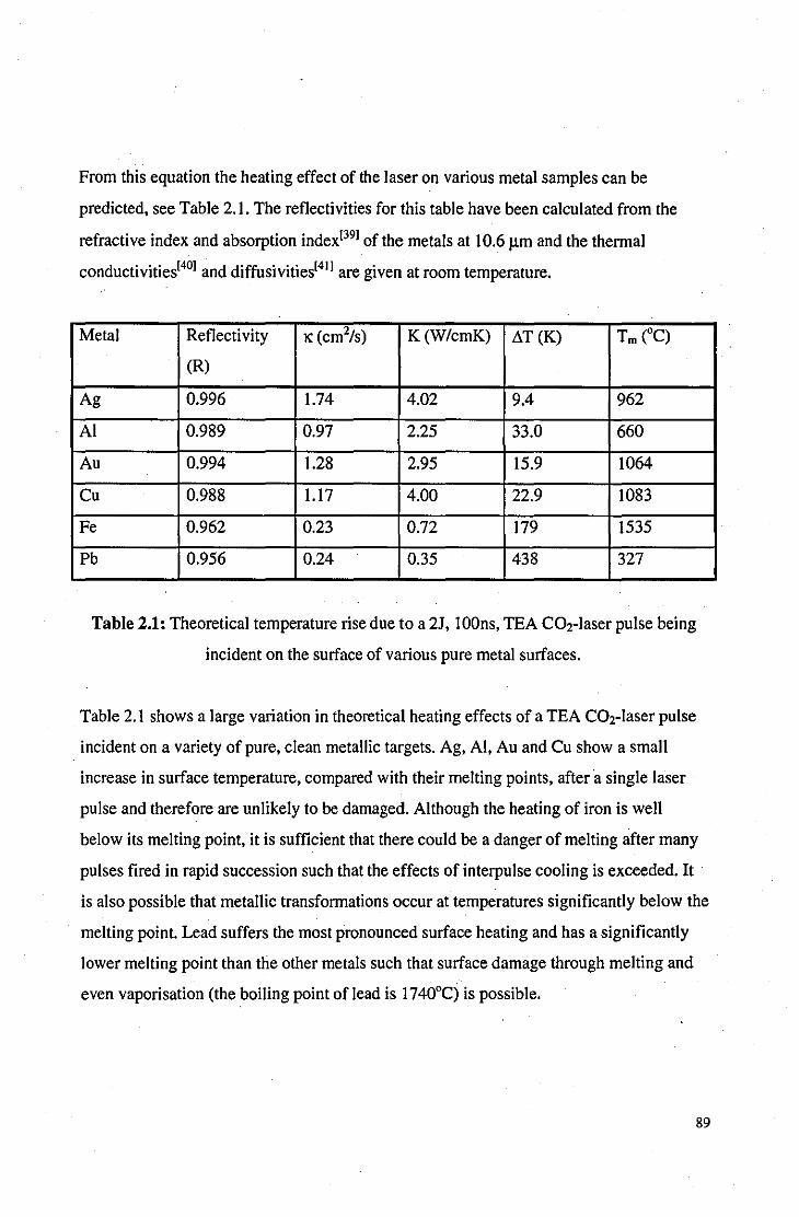
From this equation the heating effect of the laser on various metal samples can be
predicted, see Table 2.1. The reflectivities for this table have been calculated from the
refractive index and absorption index[39] of the metals at 10.6 )1m and the thermal
conductivities[40] and diffusivities[41] are given at room temperature.
Metal Reflectivity 1C (cm%) K(W/cmK) ~T(K) Tm (OC)
(R)
Ag 0.996 1.74 4.02 9.4 962
AI 0.989 0.97 2.25 33.0 660
Au 0.994 1.28 2.95 15.9 1064
Cu 0.988 1.17 4.00 22.9 1083
Fe 0.962 0.23 0.72 179 1535
Pb 0.956 0.24 0.35 438 327
Table 2.1: Theoretical temperature rise due to a 21, lOOns, TEA C02-laser pulse being
incident on the surface of various pure metal surfaces.
Table 2.1 shows a large variation in theoretical heating effects of a TEA C02-laser pulse
incident on a variety of pure, clean metallic targets. Ag, AI, Au and Cu show a small
increase in surface temperature, compared with their melting points, after a single laser
pulse and therefore are unlikely to be damaged. Although the heating of iron is well
below its melting point, it is sufficient that there could be a danger of melting after many
pulses fired in rapid succession such that the effects of interpulse cooling is exceeded. It
is also possible that metallic transformations occur at temperatures significantly below the
melting point. Lead suffers the most pronounced surface heating and has a significantly
lower melting point than the other metals such that surface damage through melting and
even vaporisation (the boiling point of lead is 1740°C) is possible.
89

2.4.1.1. Bulk temperature measurement during ablation
Introduction
If the surface temperature rise after each laser pulse is insufficient to vaporise the surface
of the target then the energy coupled with the surface is conducted both into the bulk of
the material and into the surrounding atmosphere. If, however, surface material is ablated
during irradiation, then the heated material is no longer in contact with the substrate and
direct heat conduction into the substrate is prevented. Formation of a plasma above the
target surface may induce secondary heating effects through absorption of the plasma
radiation. Hence, the surface temperature of metals during ablation of corrosion layers
involving plasma formation cannot be estimated from results such as those presented in
Table 2. I alone.
Experimental
A simple experiment was set up to monitor the temperature rise of the target material and
its reflectivity during ablation, as shown in Fig 2.4.Ih. The laser was focused to an area of
Icm2, sufficient to cause ablation without air-breakdown. The target samples were cut to
size such that they fitted the dimensions of the focused laser beam. The temperature probe
could measure with reasonable sensitivity (±D. I DC) the increase in temperature of the
bulk target material due to each laser pulse. After each pulse, the target was allowed to
cool to room temperature due to the temperature dependence of reflectivity (see Section
1.1.5). The reflectivity was determined from the ratio of the outputs from the ELTEC
detectors (0, and 02). Calibration was achieved using clean metal coupons of the target
material.
90
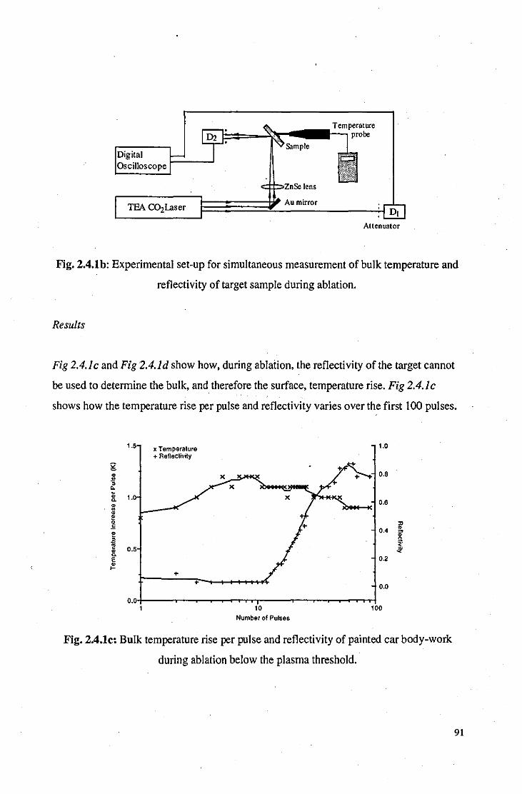
~~=--1~~~.II-T:..:elmpernture r. probe
c:::I:I:::'2:nSe lens
TEA C{)zLaser Au mirror
Attenuator
Fig. 2.4.1b: Experimental set-up for simultaneous measurement of bulk temperature and
reflectivity of target sample during ablation.
Results
Fig 2.4.1c and Fig 2.4. Id show how, during ablation, the reflectivity of the target cannot
be used to determine the bulk, and therefore the surface, temperature rise. Fig 2.4.1 c
shows how the temperature rise per pulse and reflectivity varies over the first 100 pulses.
1.5 x Temperature 1.0 + Reflectivity
g • X 0.8 !!! ,
X 0. ;; 1.0 0. 0.6 • • • ~ " £ 0.4 • e 3 • ~ 0.5 j • 0.
0.2 E • .... +
+ 0.0
0.0 1 10 100
Number of Pulses
Fig. 2.4.1c: Bulk temperature rise per pulse and reflectivity of painted car body-work
during ablation below the plasma threshold.
91

The painted car body-work consisted of a maroon top-coat with several layers of
undercoat on a zinc-coated steel substrate (0.92mm thick). The thickness of the paint
layer was measured, by micrometer, to be l2Jlm. For the first \0 pulses the temperature
rise per pulse of the bulk material gradually increases as the metal substrate is
approached. During this period, the change in the temperature rise per pulse is because of
the increasing proximity of the ablation process to the surface as opposed to the change in
reflectivity of the sample, which remains almost constant. The reflectivity of the sample
does not start to increase until after 12 pulses, when the zinc starts becoming exposed and
the temperature rise gradually starts to decrease. There then appears to be an inverse
relationship between temperature rise and reflectivity as less and less paint remains to
transfer heat to the substrate. Although the reflectivity of the target has increased from 0
to 0.8 over the entire process, the temperature increase per pulse has remained almost
constant between 0.8 and 1.2°C. This is, of course, not what might be expected if the
reflectivity was the only factor involved.
3 x Temperature + Reflectivity
..
10
Number of Pulses
.. .. X
.. 0.5
.. 0.4
X 0.3 '" • iF !l <.
0.2 ~
0.1
0.0
100
Fig. 2.4.1d: Bulk temperature rise per pulse and reflectivity ofpatinated copper-roofing
during ablation below the plasma threshold.
92
The patinated copper-roofing consisted primarily of a green, brochantite layer (as
determined by XRD) on a O.6mm thick copper substrate. The brochantite is immediately
blackened by the action of the laser. The temperature rise per pulse increases with the
reflectivity and as the metal substrate is approached, as shown in Fig 2.4. Id. This again
illustrates the fact that, during ablation, the reflectivity of the target alone cannot provide
an accurate indication as to the temperature rise of the bulk of the material. Of course, in
the absence of ablation, an increase in reflectivity would result in a decrease in
temperature rise per pulse. The patina is not completely removed by the laser and a thin
cuprite layer remains to transfer heat to the substrate.
Determination of surface temperature from bulk temperature
Although it was not possible to measure the temperature of the surface of the sample
directly during ablation, an approximate can be obtained from the bulk temperature.
By definition,
Eqn2.7
Where 8 Tb = bulk temperature rise, 8Eb = input energy, c = specific heat capacity, m = mass of target. We can define
Eqn2.8
where A,1f = the proportion ofthe incident laser radiation absorbed by the sample, and E;
= the pulse energy of the laser. Substituting Eqn 2.7 into Eqn 2.8,
Eqn2.9
93

Eqn 2.6 can be re-written as,
AT, = (2I(A,«)/K)(K tht)1I2 Eqn 2.10
Therefore, neglecting heat loss from the bulk material into the atmosphere, substituting
Eqn 2.9 into Eqn 2.10,
AT, = (2I(cm ATt! Ei)IK)(K tht)ll2 Eqn 2.11
Using Eqn 2.11 we can obtain rough estimates for the instantaneous surface temperature
rise of the painted steel and patinated copper targets. For example, a 1°C bulk temperature
rise experienced by the painted steel sample, as shown in Fig 2.4.1c, corresponds to an
estimated surface temperature rise of 94SoC. A 2°C bulk temperature rise in the patinated
copper sample, as shown in Fig 2.4.1 d, corresponds to an estimated surface temperature
rise of 396°C.
Conclusions
These results show that the transfer of energy from the laser pulse to the metal cannot be
determined from the optical properties of the surface if ablation is taking place.
The surface temperature figures are most probably considerable over-estimates. Eqn 2.10
assumes the absorption coefficient of the surface to be between 106 and 107 cm·l which is
only generally valid if the surface is metallic. Inorganic species remaining on the surface
are likely to have a much lower absorption coefficient and hence follow a far more
gradual temperature gradient. However, these figures do indicate that the surface
temperature of the metal is likely to be raised far more significantly during ablation of
surface corrosion products than if the laser is incident on a clean metal (see Table 2.1).
More sophisticated experimentation, such as using an InGaAs photodetector to capture
94
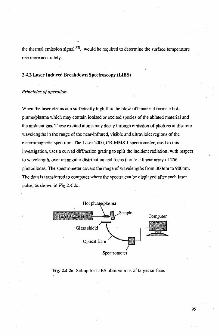
the thermal emission signal[421, would be required to determine the surface temperature
rise more accurately.
2.4.2 Laser Induced Breakdown Spectroscopy (LIBS)·
Principles of operation
When the laser cleans at a sufficiently high flux the blow-off material forms a hot
plume/plasma which may contain ionised or excited species of the ablated material and
the ambient gas. These excited atoms may decay through emission of photons at discrete
wavelengths in the range of the near-infrared, visible and ultraviolet regions of the
electromagnetic spectrum. The Laser 2000, CR-MMS I spectrometer, used in this
investigation, uses a curved diffraction grating to split the incident radiation, with respect
to wavelength, over an angular distribution and focus it onto a linear array of 256
photodiodes. The spectrometer covers the range of wavelengths from 300nm to 900nm.
The data is transferred to computer where the spectra can be displayed after each laser
pulse, as shown in Fig 2.4.2a.
Hot pIUln~/iplas:ma
Computer
Glass shield
Optical fibre
Spectrometer
Fig. 2.4.2a: Set-up for LIDS observations of target surface.
95

Attributes of UBS
Compound identification: Most elements have strong emission lines within the range of
the spectrometer. but emission lines wiIl provide only information as to the elements
present in the plasma and not the molecular formulas of the compounds at the surface.
The poor resolution of the spectrometer and the varying intensity of the plasma from one
shot to the next prevented reliable quantitative measurements being taken.
Plume/plasma analysis: apart from chemical analysis. the spectrometer can be used to
provide information on the state of the blow-off material. its temperature and the presence
of ionised species.
In-line monitoring: the appeal of LIDS over other. more sophisticated and accurate forms
of chemical analysis. is that through utilising the plume/plasma produced during the laser
cleaning process it can provide pulse-by-pulse information. The low cost of these
compact devices (less than £2500) provides the operator with a limited but useful
diagnostic technique.
60000
50000
~ 40000 c
~ 30000
~ 20000 " 0:
10000
OI~~~HH~~H#~~H#~~+HH~~H+H
g ~ ~ ~ g ~ R ~ g 8 g ~ ~ ~ ~ ~ ~~ ~ ~' ~ ~ w w ~ ~ ~ ~ ~
Wavelength (nm)
Fig. 2.4.2h: LIDS spectra of air-breakdown above an aluminium target. The peaks
correspond to the presence of nitrogen and oxygen in the air. There is no evidence for
aluminium atoms or ions present in the plasma.
96

Errors: Many problems arise from attempting to use such simple spectroscopic equipment
for accurate elemental analysis. A high flux is required to produce ionised species in the
blow-off material and air-breakdown often ensues producing a plethora of strong oxygen
and nitrogen peaks in the emission spectra, obscuring many of the target's weaker lines,
see Fig 2.4.2h. When a hot-plume forms that does not induce air-breakdown, the
emission lines of the target material are often so weak as to go undetected but for the
major components. The spatial resolution of the instrument (each photodiode covers, on
average, 4nm of the spectrum) was found to be too low to resolve some neighbouring
peaks and can lead to ambiguity in the results.
2.4.3 Acoustic monitoring
Method
During ablation an audible report (the 'ablative-piston signal') is produced by the rapid
expansion of gases and ejection of ablated materials from the formation of the hot
plume/plasma.
Hot plume
I 1EA C02Laser I \ Microphone
~Target
Digital Oscilloscop
Fig. 2.4.3a: Set-up to monitor ablative-piston signal during ablation.
A simple dynamic coil microphone can be used to measure the ablative-pulse signal
during ablation, as shown in Fig. 2.4.3a. It has been shown that the ablative-pulse signal
is proportional to the etch-depth per pulse during ablation[43l. Each laser pulse produced a
strong voltage pulse on the oscilloscope that decayed as a damped harmonic oscillator 97

within a few hundred micro-seconds. The amplitude of the strongest peak was taken as
the relative amplitude for each pulse.
Results
Fig 2.4.3b shows acoustic measurements made during the cleaning of a painted steel
target. The target consisted of a maroon top-coat with several layers of white undercoat
on a zinc-coated steel substrate and was exposed to laser pulses at 2J/cm2• There is a
pronounced variation in signal amplitude, and hence etch rate, throughout the ablation
process. The top-coat was removed within the first 3-4 pulses during which the pulse
amplitude remains quite low. As the undercoat is exposed, the signal amplitude increases
significantly between 4 and 10 pulses. After 10 pulses, the metal substrate starts to
become exposed and thus the signal amplitude starts falling.
2 -r-----------------------------,
O+--....--,.---.,r---,-----r--,---.,---j. o 10 20 30 40
La'ier pulses
Fig. 2.4.3b: Amplitude of ablative-piston signal during laser cleaning of painted car body
work.
Clearly, the etch-depth per pulse of a given laser can vary considerably for different types
of organic coating. Acoustic monitoring could provide useful feedback during the
removal of one type of organic coating from another.
98

Fig. 2.4.3c shows acoustic measurements made during the laser treatment of patinated
copper. The copper target was taken from a section of copper roofing and had a layer of
brochantite corrosion products. There was an approximately linear decrease in signal
amplitude with successive laser pulses. The etch rate of the laser reduced as the metal
substrate was approached.
4
~
!l " 'c 3 " ... " ~
'" Cl l:: :c ~ " " ~ 2 " 'C
.~ " Q. Ei ...:
" "
0
0 10 20
Laser pulses
Fig. 2.4.3c: Amplitude of ablative-piston signal during laser cleaning of patinated copper.
This gradual decrease in signal amplitude would not be expected from a homogenous
layer of corrosion products, the etch-rate of which would be approximately constant until
the metal substrate started to become exposed. It would appear that the corrosion layer is
not homogenous but varies consistently as the substrate is approached. It is reasonable to
expect a greater proportion of simple corrosion products, such as oxides, near the surface
of the metal whilst the external corrosion products consist of more complex compounds,
such as hydrates (e.g. brochantite). The signal amplitude decreases as the proportion of
the simpler compounds increases (see Chapter 5.2.1).
99

Conclusions
Acoustic monitoring has demonstrated how the etch rate per pulse varies for two different
systems; one painted and one patinated. Both systems show a great diversity in etch rate
throughout the laser treatment process. In the case of the paint, the variation in the
ablative-piston signal correlated with changes in the paint coating. In the case of the
patination, the linear decrease in ablative-piston signal as the metal substrate was
approached implied a constant variation in composition of the coating.
Summary
This chapter has described how a suitable, self-limiting laser cleaning system has been
realised and has investigated how the parameters of the laser and the properties of the
target material can affect the laser treatment process. Two clearly distinguished laser
treatment regimes have been identified, that of using the laser either above or below the
plasma threshold. The former process is best suited to laser cleaning of metal sculpture,
as described in Chapter 3, whilst the latter has application in industiial surface cleaning
and treatment processes, as described in Chapter 4.
The advantages and disadvantages of various surface analysis techniques have been
explored and these have been applied discriminately in the experimental work described
in the following chapters.
100

References
[I] Asmus, J. F., et al,' Studies in the interaction oflaser radiation with art and artefacts', Proceedings of SPIE, 41, (1973),19-27. [2] Lu, Y. F., Song, W. D., Ye, K. D., Hong, M. H., Liu, D. M., Chan, D. S. H., Low, T. S., 'Removal of submicron particles from nickel-phosphorus surfaces by pulsed laser radiation', Applied Surface Science, 120(3-4), (1997), 317,322. [3] No author cited, 'Affordable, laser-assisted chip cleaning is effective, saves water and pollutes less', Plating and Surface Finishing, 84(11), (1997),18-20. [4] Friberg, T. R., Zafiropulos, V., Kalaitzaki, R., Petrakis, J., Fotakis, C.,'Excimer laser cleaning of moldcontaminated paper', Laser in Medical Science, 12(1), (1997), 55-59. [5] Park, H. K., Grigoropoulos, C. P., Leung, W. P., Tarn, A. c., 'Practical excimer laser-based cleaning tool for removal of surface contaminants', IEEE Transactions on Components Packaging and Manufacturing Technology Part A., 17(4), (1994), 631-643. [6] Lu, Y. F., Komuro, S., Aoyagi, Y., 'Laser induced removal of fingerprints from glass and quartz surfaces\ Japanese Journal of Applied Physics Part 1,33(8), (1994), 4691-6. [7] Carlyle, L., Young, B., 'Report on laser interaction with paintings', unpublished report, Canadian Conservation Institute, Ottowa, Nov. 1981. [8] Lu, Y. F., Song, W. D., Hong, M. H., Chong, T. C., Low, T. S., 'Mechanism of and method to avoid discoloration of stainless steel surfaces in laser cleaning', Applied Physics A: Materials Science and Processing, 64(6), (1997), 573-8. [9] Lu, Y. F., Takai, M., Komuro, S., Shiokawa, T., Aoyagi, Y., 'Surface cleaning of metals by pulsed-laser irradiation in air', Applied Physics A: Solids and Surfaces, 59(3), (1994), 281-8. [10] Siano, S., Margheri, F., Pi ni, R., Mazzinghi, P., Salimbeni, R., 'Cleaning processes of encrusted marbles by Nd:YAG lasers operating in free-running and Q-switching regimes', Applied Optics, 36(27), (1997),7073-9. [11] Maravelaki, P. V., Zafiropulos, V., Kalaitzaki, M., Kowalski, R., Petrakis, J., Fotakis, C.,'Laserinduced breakdown spectroscopy as a diagnostic technique for the laser cleaning of marble', Spectrochimica Acta Part B: Atomic Spectroscopy, 52(1), (1997), 41-53. [12] Gobernadomitre, I., Medina, J., Calvo, B., Prieto, A. C., Leal, L. A., Perez, B., Marcos, F., Defrutos, A. M., 'Laser cleaning in art restoration', Applied Surface Science, 96-8, (1996), 474-8. [13] Cooper, M. I., Emmony, D. C., Larson, J., 'Characterisation of laser cleaning of limestone', Optics and Laser Technology, 27(1), (1995), 69-73. [14] Cooper, M. I., Emmony, D. C., Larson, J., 'The use of laser energy to clean polluted stone sculpture', Journal of Photographic Science, 40, (1992), 55-7. [15] Bewley, D., 'Spotless with lasers', New Scientist, (5 July 1997),20-21. [16] Morgan, N., 'Excimer lasers restore 14th century icons', Optics and Lasers Europe, (Sept 1993),36-37 .
. [17] Szczepanowska, H. M., Moomaw, W. R., 'Laser stain removal of fungus-induced stains from paper', JAIC, 33, (1994), 25-32. [18] Hecht, J., from The Laser Guidebook, 2nd Ed., McGraw-Hill Inc., London, (1992), 159-183. [19] Russo, R. E., 'Laser Ablation', Applied Spectroscopy, 49(9), (1995), 14A-28A. [20] Garrison, B. J., and Srinivasan, R., 'Laser ablation of organic polymers: Microscopic models for photochemical and thermal processes', J. Appl. Phys .. 57(8), (1985), 2909-14. [21] Prokorov, A. M., Konov, V. I., Mihailescu, I. N., 'Laser heating of metals', Adam Hilger Series on Optics and Optoelectronics, Bristol, (1990), 30-35. [22] Prokorov, A. M., Konov, V. I., Mihailescu, I. N., 'Laser heating of metals', Adam Hilger Series on Optics and Optoelectronics, Bristol, (1990), 35. [23] Weisheit, A., Mordike, B. L., 'Laser Nitriding of Titanium Alloys', Surface Engineering, 11(2) (1995), 160-1. [24] Riches, S., 'An introduction to the fundamentals oflaser technology', Lasers and Power Beam Processing, (Sept 1996), 17-9. [25] Ready, J. F., from 'Effects of High-Power Laser Radiation', Academic Press, London, (1971), Chapt. 5. [26] Cooper, M., Doctoral Thesis, 'Laser cleaning of stone sculpture', (28 April 1994), 159.
101

[27] Critchlow, G. W., Cottam, C. A., Brewis, D. M., Emmony, D. C., 'Further studies into the effectiveness ofCO,-laser treatment of metals for adhesive bonding', Int. J. Adhesion and Adhesives, 17, (1997), 143-150. [28] ELTEC Instruments SA, P.O.Box 564, Neugutstrasse 4, CH-8304 Wallisellen, Switzerland. [29] Cooper, M., Doctoral Thesis, 'Laser cleaning of stone sculpture', (28 April 1994), 188-202. [30] Gurevich, V. S., Danilov, O. B., Popov, Y. G., Yachnev,I. L., 'CO,lasers for medical uses', Journal of Optical Technology, 61(12), (1994), 928-31. [31] Ad idem, 206. [32] Hecht, J., from The Laser Guidebook, 2nd Ed., McGraw-Hill, London, 171. [33] Mc Clune, W. F., (Chief Ed.), from Powder Diffraction File: Alphabetical Index, Inorganic Phases 1987, JCPDS, International Centre for Diffraction Data, Swarthmore, USA (1987). [34] Critchlow, G. W., private communication. [35] Zisman, W. A., 'Relation of the equilibrium contact angle to liquid and solid constitution', from Contact Angles and Wettability and Adhesion, American Chemical Society, Washington, (1964), I-51. [36] Adam, N. K., 'The chemical structure of solid surfaces as deduced from contact angles', from Contact Angles and Wettability and adhesion, American Chemical Society, Washington, 56. [37] Scot!, D. A., from 'Metallurgy and Microstructure of Ancient and Historic Metals', The Getty Conservation Institute, Singapore, (1991), 69-74. [38] Ready, J. F., from 'Effects of High-Power Laser Radiation', Academic Press, London, (1971), Chapt 3.5. [39] Prokorov, A. M., Konov, V. I., Mihailescu,I. N., 'Laser heating of metals', Adam Hilger Series on Optics and Optoelectronics, Bristol, (1990), 6. [40] Touloukian, Y., S., from 'Thermal Properties of Matter: Thermal Conductivity of Metallic Elements and Alloys', The TPRC Data Series Vo!. l.,lFIIPlenum, (1970). [41] Touloukian, Y., S., from 'Thermal Properties of Matter: Thermal Diffusivity', The TPRC Data Series Vo!. 10., IFIlPlenum, (1973). [42] Chen, S. c., Grigoropoulos, C. P., 'Noncontact nanosecond-time-resolution temperature measurement in excimer laser heating of Ni-P disk substrates', Applied Physics Letters, 71(22), (1997), 3191-3. [43] Leung, W. P., Tarn, A. C., 'Non-contact monitoring of laser ablation using a miniature piezoelectric probe to detect photoacoustic pulses in ai(, Applied Physics Letters, 60(1), (1992), 23-5.
102

Photo 2.1.4a: Ti mc-ex poscd pholograph of hOI-plulllc formal ion abovc a coppcr-rool·i ng largel aflcr a single lascr pu lsc al 2J/c m2 Thc irrad ialcd arca is approximalely 10mm in height.
Photo 2.I .4b: Timc-cxposed photograph of IWO silcs of plasma ini l ial ion abovc a coppcrroofi ng largcl aflcr a si nglc lascr pulsc al 4J/c m2 The irrad ialcd arca is approx imalel 7111m in height.
103

CHAPTER 3
Sub-plasma Laser Cleaning and Treatment
3.1 Artificially patinated samples
A major obstacle in the path of much of the research into the laser cleaning of all forms of
artwork and historical artefacts is the scarceness of test-samples on which new laser
techniques can be tried without the risk of permanent damage to valuable objects. Even
when it is considered acceptable to risk preliminary laser cleaning tests on less-valuable
items there are often difficulties in bringing the objects within the vicinity of the laser due
to their size. For example, the TEA C02-laser used in our experiments weighed 120kg
and required a separate gas supply which prevented its transportation without great
difficulty, whereas the outdoor sculpture that would serve as ideal test objects were
equally immobile and far removed from the vicinity of the laser. Thus, artificially creating
coated metal coupons within the laboratory to mimic the effects of corrosion and
patination was attempted for initial cleaning tests without the danger of damaging
valuable objects.
The patination recipes used by patineurs throughout history have produced coloured
layers on metals that are in general chemically unrepresentative of the patination caused
by prolonged outdoor exposure. Patina applied at the foundry rarely survives on outdoor
sculpture without being converted or removed completely[l) by prolonged exposure to
rainwater. In this study, the artificial patination experiments were used for two reasons:
(i) to reproduce the patination layers produced by foundry patineurs
(ii) to mimic the corrosion/patination effects of long-term exposure
\04

Foundry patineurs
3.1.1 Experimental
Materials
The majority of sculpture is cast in copper alloy and for this reason metal coupons were
cut from copper sheet (CI06, 99.85% commercial purity) and gunmetal bronze ingot (BS
. 1400, see Appendix C) which is a popular alloy for casting. Some experiments were also
carried out on coupons of sterling silver (precise composition not known, although
sterling silver typically contains up to 10% copper). The coupons dimensions are shown
in Fig 3.1.1a.
2.5cm 2.5cm
thickness = 3.2mm thickness = 0.5mm thickness = 3-6mm
Fig 3.1.1a: Copper, silver and bronze coupons used in artificial patination experiments.
Each coupon was numbered for identification purposes.
105

The copper and silver sheet could be cut using a guillotine whereas the bronze ingot,
because of its shape, required the use of a circular saw and each coupon required a certain
degree of finishing to obtain a reasonable surface for patination. Coupons were cleaned
prior to patination using wire-wool and degreased with high purity acetone. The
coloration process is very sensitive to the presence of surface contamination, in particular
grease and oil which prevent uniform wetting of the surface. The surface of one of the
bronze coupons was etched in FeCI) solution to reveal the grain-structure. Typically,
grains had dimensions of a few millimetres wi th a slight reduction in size where the ingot
was in contact with the mould.
Long-tenn exposure effects
The corrosion caused through long-term exposure usually involves the subjection of the
object to cycles of wetness and temperature variation, and Iow-concentrations of solution,
such as rainwater. To introduce a cyclic nature to the experimental set-up a simple
'dipping machine' was constructed, as shown in Fig 3.1.1b, to alternately dip and
withdraw the metal coupon from a weak chemical solution. A fan was sometimes used to
increase the rate of evaporation of the solution from the surface of the coupon which
could have a significant effect on the qualities of the patina.
Stepper Motor
Pulley System
Fig. 3.1.1b: Artificial patination using a 'dipping machine'.
106

Laser cleaning
The specific details of the laser cleaning and the patination process will be described as a
series of case-studies from Case la to Case 9a (the a represents artificial). In general,
trial tests were made using different laser fluences on each test-piece in order to
determine which produced the most desirable effect.
Surface analysis
When patina formed of sufficient thickness, XRD could be used to identify the corrosion
products. Most XRD analysis was performed at a rate of 1 degree per minute (dpm) and a
typical scan required about an hour and a half as the goniometer swept from 10 to 90
degrees. If a corrosion layer was very thin or particularly complex, the rate was reduced to
0.1 dpm and an overnight scan was performed to reduce the relative fluctuations in
background noise that may be otherwise misinterpreted as diffraction peaks. In the results
that follow in this chapter, the corrosion compounds may be referred to by their mineral
names, a glossary of which may be found in Appendix H.
The diffraction pattern of gunmetal bronze, perhaps because of its complex formulation,
is absent from the powder diffraction files. A cleaned gunmetal bronze coupon provided a
standard diffraction pattern which could be used to eliminate bronze peaks whilst
analysing corrosion on patinated bronze coupons.
When quantitative analysis was required, such as with the silver coupons in Case 7a and
Case Ba, AES was used.
107

3.1.2 Case la
Introduction
A common affliction of copper and copper containing artefacts stored in wooden boxes is
the formation of corrosion products from vapours emitted from the wood of th.e boxes or
protective lacquers that have been applied to the WOOd[31. The precise nature of the
corrosive vapours depend on the wood and lacquer types, although a common constituent
is acetic acid. The object of this experiment was to replicate a possible corrosion layer
that may form on a copper objec(exposed to such an environment.
Patination method
Attempts at exposing coupons to dilute acetic acid did not produce any corrosive effects
other than mild oxidation and ammonium chloride was added to facilitate the reaction.
The patination solution consisted of 19 N~Cl and 19 Cu(C2H302)2 dissolved in 250mi of
distilled water at room temperature. The copper coupon was dipped over a i 0 minute
cycle for 48 hours. After the first 24 hours a brown patina had formed, for the last 24
hours a fan was used to accelerate the evaporation rate of the solution from the surface of
the coupon.
Pre-laser treated coupon
The patination method resulted in a uniform, adherent blue patina over the surface of the
coupon, under which a thin brown layer had formed. XRD of the surface revealed the
major constituents of the corrosion products to be Cu(OH)Cl and CuC2H302.
108

Laser treated coupon
At a fluence of 0.5 J/cm2 the laser produced a luminous plume, but no breakdo~n, that
completely removed the blue layer within a few pulses, leaving the brown layer
unaffected, see Photo 3.I.2a. Further exposure to the laser at this fluence did not have any
visible effect on the appearance of this layer. Increasing the fluence to 2 J/cm2 also
created a hot plume and although the blue layer was successfully removed, the underlying
brown layer quickly darkened with prolonged exposure to the laser.
XRD of the laser treated area showed that the remaining brown layer was too thin to be
identified, all detectable Cu(OH)CI and CUC2H302 had been removed.
Discussion
The laser was successful at removing the external corrosion products formed on copper in
the presence of acetates and chlorides. At 0.5 J/cm2 the laser was clearly able to
selectively remove the blue corrosion without visibly altering the brown interfacial layer,
although an unpleasant charring of the interfacial layer occurred at higher fluences. In the
absence of XRD data it is difficult to determine the nature of the charring although it
seems reasonable to assume that it is caused through the thermal decomposition of
residual corrosion products to leave, for example, a black tenorite layer.
3.1.3 Case 2a
Introduction
The effect of the fan was investigated by repeating the experiment in Case la, but this
time using the fan for the full 48 hours of dipping as opposed for the last 24 hours.
109

Patination Method
As in Case 1 a, with the fan used for the full 48 hours.
Pre-laser treated coupon
The patination method resulted in a patina of greater thickness and different coloration
than in Case la. The colour gradually varied between blue and green over the surface of
the coupon and an underlying red layer was evident, see Photo 3.1.3a. XRD identified the
compounds to be primarily CU2CI(OH}J, CuCI and CuC2H302'
Laser treated coupon
The laser removed the blue/green surface layer within a few pulses at a fluence of 2J/cm2
whilst leaving a uniform red layer underneath that did not discolour with further
irradiation, see Photo 3.1.3b. XRD of the laser-treated area detected only CuCI, hence all
detectable CU2CI(OH}J and CuC2H302 had been removed. It is very likely, however, that
significant levels of compounds other than CuCI were present as pure CuCI is usually
white in appearance. Over the period of a few months, the red surface started to blacken
and XRD detected the presence of CuCI and CU20.
Discussion
The sensitivity of the patination process to a slight variation in method is illustrated when
this case is compared to Case la and the difference in corrosion products considered.
Again, we see the laser capable of removing the external corrosion products whilst a
resilient interfacial layer remains. Unfortunately, CuCl remained on the surface of the
laser cleaned sample and observations of the surface, which had blackened after a period
of a few months, showed the remaining layer to be unstable. The formation of CU20 in
the CuCllayer is a strong indication of bronze disease (see Section 1.3.3).
110

3.1.4 Case 3a
Introduction
The rainfall in urban areas contains many species of chemicals, such as nitrates, sulphates
and chlorides, that act synergistically to accelerate the corrosion of copper sculpture. In
Case 3a a copper coupon is patinated in the presence of such chemicals.
Patination method
The patination solution consisted of Ig NaCI, Ig CuS04.5H20, Jg CUN03.3H20
dissolved in 250ml of distilled water at room temperature. The coupon was dipped over a
10 minute cycle for 72 hours and continuously fanned.
Pre-laser treated coupon
The patination solution produced a very rough corrosion layer; the coloration varying
between blue, green and white over the surface. There is evidence of an underlying, thin
red layer beneath the bulk of the corrosion products. XRD identified a variety of chlorides
including two forms of CU2CI(OHh (one being atacamite), Cu(OH)CI and CuCI
(nantokite).
Laser treated coupon
At 2J/cm2 the laser removed most of the blue/green/white layer to reveal the underlying
red layer, see Photo 3.I.4a. However, some filiform corrosion products, blackened by the
action of the laser, remained resilient to removal at sub-plasma fluences, see Photo
3.I.4h. XRD identified the remaining corrosion to be CuCI (nantokite) and CU2CI(OHh.
From the coloration and location of the corrosion products, it is reasonable to assume that
111
the red layer consists mostly of CuCI whereas the blackened remains contain a high
proportion of CU2CI(OHh.
Cross-sectional analysis clearly shows the existence of a red interfacial layer between the
copper metal and bulk corrosion products, see Photo 3.1.4c, prior to laser treatment and
this red layer remaining post-treatment.
Discussion
The patinating solution contained a mixture of sulphate, nitrate as well as chloride
compounds, but the corrosion layer consisted purely of chlorides of various forms. This
was not surprising because chloride ions in solution have the ability to convert otherwise
stable corrosion products, such as brochantite, into chloride compounds[41. Although the
concentration of the patination chemicals were far in excess of any natural rainfall, the
patina consisted of compounds commonly observed on naturally corroded copper in
marine environments. The active nature of chloride compounds in corrosion layers makes
their removal almost always desirable. The bulk, external corrosion products were
completely removed except in the case of the filiform CU2CI(OHh, which was blackened
but not removed. The blackening is due to the thermal decomposition of CU2CI(OHh to
solid black CuO and the expUlsion of gaseous HCI and H20. The tenorite that remains
forms a thin black layer on the surface of the CU2CI(OH)3 fibrils of insufficient thickness
to be detected by XRD. The cross-section shows that the resilient, interfacial red layer
existed prior to laser cleaning and has not formed from the action of the laser on the metal
substrate or external corrosion products. Again, the laser has been successful at removing
the bulk of the corrosion products whilst leaving a resilient interfacial layer, but in this
case laser-transformed corrosion products, such as tenorite, also remain on the surface.
The high proportion of chlorides remaining on the surface indicates that this layer,
resilient to laser ablation, is unstable and unprotective.
112

3.1.5 Case 4a
Introduction
CU20 (cuprite) is a very common corrosion product which occurs on copper and copper
alloys as an interface between the metal substrate and the external corrosion products.
The coupon used in Case 4a replicates the brown cuprite layers that may be found, for
example, on modern copper coins after a few years of use. Cuprite coatings have been
known to be applied by patineurs(S].
Patination method
A patinating solution of 5g CUN03.5H20 in 25ml of distilled water was made up and
boiled. The copper coupon was immersed in the boiling solution for 20 minutes then
removed and rinsed first in hot water, then cold distiIIed water.
Pre-laser treated coupon
The coupon had formed a thin, uniform and adherent, brown patina. XRD identified only
CU20 (cuprite) to be present.
Laser treated coupon
The laser had no visible effect upon the brown surface layer at sub-plasma f1uence, nor
was there any visible plume formed or audible shock. Increasing the f1uence above the
plasma threshold caused non-uniform blackening of the patina radiating across the
surface from the area of irradiation.
113

Discussion
Oxides often form interfacial corrosion layers between the metal substrate and external
corrosion products and usually form a passivating film during the initial corrosion
process. Removal of the oxide would leave the metal substrate exposed to further
corrosion and is seldom desirable. Thus, the fact that the laser left the oxide layer
unchanged at sub-plasma fluences is generally desirable.
3.1.6 Case Sa
Introduction
Gunmetal bronze is commonly used in outdoor sculpture and hence the patina formed is
often a product of the action of chlorides, sulphates and nitrates. The patination of bronze
in the presence of such chemicals is investigated in this case.
Patination method
The patination solution consisted of Ig NaCI, Ig CuS04.5H20 and Ig CUN03.3H20
dissolved in 250ml of distiIIed water at room temperature. The coupon was dipped over a
10 minute cycle for 72 hours and continuously fanned whilst out of the solution. The
patin~tion process was identical to that of the copper coupon described in Case 3a.
Pre-Iaser treated coupon
The bronze formed an adherent, smooth, deep blue patina which varied slightly in tone
over the surface. Some visibly large crystaIlites of corrosion, up to a miIIimeter in
diameter, had formed near the jagged surface that would have been exposed whilst the
ingot was being cast. There also appeared to be a brown underlying corrosion layer. XRD
114
revealed the presence of CuCI2.3Cu(OHh (basic copper chloride), CuCI (nantokite) and
CU2CI(OHh in the corrosion layers.
Laser treated coupon
The coupon was irradiated with a fluence of 2J/cm2 which removed the external, blue
corrosion layer within several pulses, see Photo 3.1.6a. A brown layer remained that was
not visibly effected by the laser at sub-plasma fluences. The thickness of the brown layer
varied considerably over the area of the treated coupon, in some areas the etched surface
. of the granular bronze is clearly visible, whereas in other areas the layer obscures the
metal surface completely. X-ray spectra of the brown layer did not elicit any clear
information as to its nature, probably due to its thinness.
Discussion
Although the bronze in Case 5a was patinated under the same conditions as the copper in
Case 3a, the resulting corrosion products were significantly different. The most
pronounced difference between the two systems was the visual appearance of the laser
treated areas, red in the case of the copper and dark brown in the case of the bronze.
Although the dark brown coloration of the treated bronze was attractive and the bulk of
the aggressive chlorides had been removed, the protective qualities and stability could not
be determined due to the lack of chemical information.
3.1.7 Case 6a
Introduction
(Cu,ZnhCOHhCI (anarakite) is a corrosion product that may commonly appear on
brass[6,7j from exposure to chloride species. Anarakite has been known to appear on
gunmetal bronze which also has a high zinc content.
115
Patination method
Concentrated HCI(nq) was dropped by pipette onto the surface of a bronze coupon and
allowed, over the period of a few days and in the confines of a fume-cupboard, to
evaporate.
Pre-laser cleaned coupon
The patinating solution produced a uniform, relatively thick, adherent, pale turquoise
patina. XRD produced strong peaks for the presence of anarakite and atacamite in the
patina, and also some evidence for the presence of ~-ZnOHCI.
Laser cleaned coupon
The laser was used at a fluence of 2J/cmz, sufficient to remove the external corrosion
products within a few pulses. The remaining surface retained a thin uniform brown layer,
through which the grain structure of the etched bronze surface could be observed, see
Photo3.1.7a.
XRD detected the presence of CuCI and SnOz in the remaining brown layer. A cross
section taken through the coupon shows that the brown layer existed prior to the laser
treatment process, see Photo 3. I. 7h.
Discussion
Again, the cleaning process has been limited by a thin, resilient surface layer that existed
on the original patinated coupon. The presence of chlorides in this layer implies that it is
unstable although the colour is not unpleasant.
116

3.1.8 Case 7a
Introduction
The most common fonn of tarnish on silver is Ag2S, This tarnish is simple to create by
exposing the silver to H2S and water in an oxygen-rich environment[81. Silver does not
naturally fonn bulk oxide layers, therefore, by investigating the effects of the laser on the
sulphide layer, any oxidising effects caused by the laser can be readily identified. In the
previous cases, any evidence for laser-induced oxidation was difficult to identify because
there were already oxides present.
Patination method
A sterling silver coupon was suspended above a solution containing 4g of Na2S.9H20
dissolved in 100ml of distiIIed water. The solution was kept at a temperature of 60°C by
use of a hot-plate and the coupon was left for a period of two hours. The coupon was then
rinsed thoroughly in running water.
Pre-laser treated coupon
The sterling silver had fonned a thin, dark grey, adherent coating. The coating was too
thin to determine its fonnulation through XRD analysis. AES was used to detennine the
composition ofthe corrosion products (see Table 3.1).
Area Etch(s) Cl Na C Ag S Cu 0 AglCu AglS
(at%) (at%) (at%) (at%) (at%) (at%) (at%)
A 0 IO 4 20 20 33 5 8 3.8 0.6
B 0 14 2 20 21 27 8 9 2.8 0.8
B 60 1 I 0 42 47 IO 0 4.3 0.9
Table 3.1: AES surface scan of sterling silver prior to laser treatment.
117

AES was performed on two areas which shall be called A and B respectively. The depth
of the analysis was estimated to be between 2 and 4nm. The untreated corrosion layer has
a large amount of atmospheric organic contamination that accounts for the high levels of
Cl, Na, C and 0 present. The 0 may also be due to an Ag20 layer that has been known to
form to the depth of a few angstroms on silver in the presence of oxygen. A 60 second
argon ion etch was performed to give information about the bulk of the corrosion
products and reveals the presence of only Ag, Sand Cu in significant quantities and no
evidence of oxygen at all. Clearly, the copper and silver are present as sulphides only.
Laser treated coupon
Laser treatment was performed at both sub-plasma (Sample I) and plasma (Sample 2)
fluences (see Table 3.2).
Sample Area Etch(s) Cl Na C Ag S Cu 0 AglCu AglS
( •• %) (aI%) ( •• %) ( •• %) ( •• %) ( •• %) ( •• %)
I A 0 I I 2 46 35 IO 5 4.6 1.3
I B 0 2 2 I 35 41 II 7 3.2 0.9
2 A 0 0 J 0 52 32 9 5 5.5 1.6
2 B 0 J 0 J 50 28 \3 6 3.8 1.8
Table 3.2: AES surface scan of sterling silver after sub-plasma (Sample I) and plasma
(Sample 2) laser treatment.
Sample I
The visual appearance of the sub-plasma treated coupon was virtually indistinguishable
from the untreated coupon, the dark layer remained but had a slightly more diffuse
appearance. The laser produced a weak, hot-plume for one or two pulses at 2J/cm2 after
which there was no visible interaction. The sub-plasma treated coupon shows a radical
decrease in surface organic contamination; the low levels of detected C, Na and Cl
liS

probably being due to recontamination from exposure to the laboratory atmosphere
between the time of laser treatment and AES analysis. Ag, Cu and S levels are of similar
value as the pre-laser treated etched sample.
The presence of oxygen in the absence of significant organic contamination suggests that
the laser has converted some of the sulphides to oxides. It is interesting to note the CulO
ratio is typica\1y 2: I, suggesting the conversion of copper sulphides to cuprite.
Sample 2
The plasma treated coupon shows a further reduction in the levels of Cl, Na and C. There
is no significant change in the Ag, S, Cu and 0 levels with respect to the sub-plasma
treated coupon. Again, there was little visible difference between the plasma treated and
untreated coupons.
Discussion
At both plasma and sub-plasma fluences the laser has reduced the level of organic
contamination on the surface of the tarnish layer. The laser has also induced some
oxidation at the surface of the tarnish which is absent from the bulk corrosion products.
The high levels of Cu in the tarnish is due to its presence as a sacrificial component in
sterling silver.
3.1.9 Case 8a
Introduction
The experimental method of Case 7a was repeated, but with the sterling silver coupon
replaced with a high purity (99.95%) silver coupon. It was hoped that by almost
eliminating the copper component that reaction chemistry would be simplified.
119

Patination method
See Case 7a.
Pre-laser treated coupon
Area Etch(s) C Ag S Cu 0 AglS
(at%) (at%) (at%) (at%) (at%)
A 0 39.4 23.1 15.5 4.1 17.9 -B 0 27.8 30.3 15.2 6.9 19.8 -B 20 0 66.7 33.3 0.0 0.0 2
Table 3.3: AES surface scan of high-purity sil ver prior to laser treatment.
In Table 3.3, the non-etched, pre-laser treated coupon shows the expected high levels of C
due to atmospheric contamination. There is also a significant copper peak that was
unexpected in such high purity silver, although the Cu does not appear to be present in the
bulk of the tarnish layer. After etching the only elements detected are Ag and S in the
expected 2: I (i.e. Ag2S) ratio.
Laser treated coupon
Laser treatment was performed at both sub-plasma (Sample I) and plasma (Sample 2)
f1uences, see Table 3.4 (overleaf).
Sample 1
The non-etched coupon shows a large reduction in C after sub-plasma laser treatment at
2J/cm2 although high levels of 0 remain. There is little change in the levels of Ag, S, Cu.
After a 20s etch, the only elements detected are Ag and S, although the ratio has increased
to 2.48 in comparison to 2.00 in the untreated sample.
120

Sample Area Etch(s) C Ag S Cu 0 Ag/S
(.t%) (at%) (at%) (.t%) (.t%)
1 A 0 11.2 44.9 21.2 8.1 14.6 -1 B 0 12.4 36.2 15.8 6.5 29.2 -1 B 20 0 71.3 28.7 0.0 0.0 2.48
2 A 0 3.4 20.8 4.0 10.9 60.7 -2 B 0 4.0 33.2 8.7 4.6 49.4 -2 B 20 0 66.9 24.1 0.0 9.1 2.78
Table 3.4: AES surface scan of high-purity silver after sub-plasma (Sample I) and
plasma (Sample 2) laser treatment.
Sample 2
The non-etched coupon shows a further reduction in C after plasma treatment. Whilst Ag
and Cu levels remain about the same, 0 levels have increased greatly and S levels have·
been significantly reduced. The action of the plasma has been apparently to convert the
surface sulphides to oxides. After a 20s etch, the Ag:S ratio has increased to 2.78 and the
presence of 0 remains significant.
Discussion
Although the non-etched silver coupons exhibited strong copper peaks, copper was not
present in the bulk of the tarnish, unlike in the case of the tarnish layer on sterling silver
(see Case 7a). This indicates a duplex system with copper corrosion products forming a
layer on top of silver corrosion products. The high levels of copper compounds at the
surface of the tarnish implies that there is migration of copper ions to the surface during
patination giving the top 15nm or so a copper concentration far in excess of that of the
bulk material. Copper is generally the most common impurity in commercial silver
because native silver ore often has a high copper content, some of which remains after the
refinery process. The estimated etch rate of the ion-bombardment system is 45nmlmin
(based on a silver standard). The 20s etch would therefore have penetrated to a depth of 121
approximately l5nm, after which no copper was detected in the pre-laser treated coupon.
The fact that copper remains after sub-plasma and plasma fluences shows us that the laser
has removed less than l5nm of tarnish, if it has removed any at all.
As in Case 7a, the laser plasma is more effective at removing organic contamination than
the sub-plasma beam. Although there is some evidence for the conversion of sulphides to
oxides at sub-plasma fluences, this effect is far more pronounced at plasma fluences to
the extent that the sulphide peaks were almost eliminated. The oxide peaks after plasma
treatment remained significant even after a 20s etch.
In conclusion, the laser cannot be used to remove tarnish from silver. The hot-plume
created by the laser during the first couple of pulses is due to the ablation of organic
contamination from the surface of the tarnish layer. At plasma fluences, some evidence of
surface oxidation was found although after a 20s etch (Le. just a few tens of nanometers)
. the oxide level was reduced to 20% of that at the surface. Hence, even at plasma fluences
the oxidising effect of the laser on silver tarnish is quite superficial.
3.1.10 Case 9a
Introduction
Much of the past and contemporary research on iron conservation has been focused on the
removal of chlorides from the corrosion layer[9-13J. In Case 9a, a mild steel coupon is
rusted in a saline solution to cause corrosion containing a mixture of oxides and
chlorides. To investigate whether a complex topography might affect the laser cleaning
process, the coupon was punched with numerals to create features on the surface. Real
iron objects will often present a complex relief, especially if they are significantly
corroded.
122

Patination method
4g of NaCl was dissolved in 250ml of distilled water. The mild steel coupon was dipped
into the solution over a ten minute cycle for 24 hours.
Pre-laser treated coupon
The mild steel coupon had a fairly uniform, orangelbrown corrosion layer over its surface.
The corrosion of the punched numerals appeared identical to that of the rest of the
surface. XRD analysis revealed most significant peaks for ~-Fe2(OHhCl and also strong
peaks for E-Fe203 and FeOOH. The metal substrate appeared as a-Fe.
Laser treated coupon
Laser treatment was performed at a fluence of 2J/cm2. After 2-3 pulses, all visible
evidence of rust had been removed from both the surface and the punched numerals, see
Photo 3.1.1 Oa. The exposed steel had a pitted appearance due to the affects of corrosion.
XRD was not performed on the cleaned area because the technique is not sensitive
enough to detect corrosion layers too thin to be seen with the naked eye.
Discussion
The rust layer was unsightly and, due to the presence of chloride compounds, aggressive.
Therefore, its removal could be warranted even though the metal substrate has been
exposed, but the steel may require further treatment to prevent the corrosion process re
starting. The ability of the laser to penetrate into the fine detail of the numerals illustrates
a clear advantage of laser cleaning over some more conventional cleaning methods.
123
3.2 Naturally Patinated Samples
The results from the artificially patinated coupons give some indication as to how certain
metal/corrosion systems respond to laser treatment but they cannot be relied upon to
accurately represent real-life corrosion systems. Fortunately, sculpture is not the only
form of metal structure exposed to long-term, atmospheric effects and a number of
naturally patinated samples were obtained from alternative sources. Through the kindness
of National Museums and Galleries on Merseyside (NMGM) and Newarke Housing
Museums, Leicester, some tests were also made on genuine sculpture and artefacts.
3.2.1 Case In
Introduction
. Of all the corrosion products found on outdoor copper and copper alloys, brochantite, the
basic copper sulphate, is probably the most written about[14-18J. Attempts to form a
brochantite patina on copper and bronze under laboratory conditions were unsuccessful
and the author knows of no reference to how this may be formed artificially. Fortunately,
due to some re-roofing to the halls of residence around the university campus, patinated
copper roofing became available to us which contained a high percentage of brochantite
in the corrosion layers. Part of the roofing, positioned at a slight angle to the horizontal,
had formed a uniform, green patination layer and it is from this section that coupons were
cut for our investigation for Case In. Another part of the roofing was positioned
vertically and had patinated very differently with a very dark under-layer over which
green speckles were scattered.
Pre-laser treated coupon
The O.6mm thick copper roofing was cut into coupons of 80mm x 30mm for ease of laser
processing and surface analysis. The pale green patina that had formed was uniform,
124
adherent and smooth. XRD produced very strong peaks for the presence of CU4S04(OH)6
(brochantite) and some Cu2Cl(OHh, Some evidence for CU02 (cuprite), CuCl (nantokite),
CU2S04 and CU20(S04) (dilerophantite) was also found. Identification of the substrate
was complicated by the fact that copper-metal and CU3.8Ni (an alloy commonly used in
roofing) have virtually indistinguishable powder diffraction patterns: SEM spot-analysis
failed to detect any nickel in the cleaned copper sample and therefore the roofing material
was taken to be copper. Cross-sectional analysis of the coupon did not reveal any
evidence of an interfacial layer between the green patina and the metal substrate, see
Photo. 3.2. lb.
Laser treated coupon
The laser interacted with the patina at low fluences of O.5J/cm2 to produce a
browning/blackening effect without any significant ablation. A much stronger interaction
occurred around 2J/cm2 producing a hot-plume, see Photo 2.1.4a (previous chapter). At
this higher fluence the blackening of the patina that remained was very pronounced. XRD
of the blackened patina revealed a significant increase in the presence of cuprite. After
about 15 pulses the laser treatment was complete (i.e. there was no more laser interaction)
and a grey layer remained, see Photo 3.2. la. XRD, performed at O.ldpm, identified strong
cuprite peaks in the remaining layer, with some evidence for CuCl (nantokite) and CU2S
(chalcocite ).
Cross-sections taken of the laser treated samples were unsuccessful due to the remaining
surface layer having a tendency to dissolve in the embedding resin.
Laser-induced breakdown spectroscopy
LlBS spectra were taken at three different fluences during the laser treatment of the
copper roofing, see Fig 3.2.1 c. At the normal cleaning fluence of 2J/cm2 the ablation
plume was absent of any ionisation peaks. A slight increase in fluence ('low plasma')
125

allowed for some ionisation to be observed without significant alteration in the
appearance of the ablation plume. The five significant peaks observed at this fluence all
correspond to copper ions showing that ionisation of the blow-off material can occur prior
to air-breakdown. A further increase in fluence to 4J/cm2 ('plasma') radically changes the
colour of the plume from orange to bright blue, see Photo 2.1.4b (previous chapter). The
spectra shows very strong copper peaks (I, 5, 8, 10, 14 and 18); the other peaks were
identified as nitrogen and oxygen from the air. No other elements could be identified
from the spectra.
'. '. 5OOlO '. · . · . <0000 '. · . · .
j"':mlO '. · . . , I " I',' t· •• ' I 4, I
"
C"""" Roofing
" '. , • PI,am.
~ 11'. .' .
" " . . .. ..
11 ' •
10000 .... . '2~3J"\. - - -:~ ........
LowPlaom.!\ ".. """' •• '.' • .' 2021 ...... I I' '"'- --/ 18 17 '.'~. 22 23
"- - ...... - PI~m. • •••
o
~ ~ @ ~ ~ ~ ~ ~ ~ ~ @ ~ ~
Wa\<lIO'1gIh
a'....x.ag
Fig. 3.2.1c: LIBS spectra of copper roofing irradiated at three different fluences.
FT-JR spectroscopy
The resilience of the cuprite layer compared to the brochantite layer can be explained by
their IR absorbance spectra. Figs 3.2.1d and 3.2.1e show the absorbance spectra for
brochantite and cuprite respectively. As can be seen, brochantite has some broad, high
absorbance bands from 500 to 4000cm- I, one occurring between 600 and 1200cm- I (i.e.
between 8.3 and 16.7~m). Cuprite, however, does not show significant absorptivity
between 5 and 16. 7~m. Hence, the 1O.6~m radiation is absorbed far more significantly by
the brochantite layer as opposed to the cuprite layer.
126

O.5S 0,34
0.00 1=~_-,. __________ ----"'00 J::~ ___ "::::====:!'_~~ __ 4000 )000 2000 Hloo 4000 '''' 2000
Wavcnumbcrs (cm") 1000
Wavenumbcn (cm")
Fig 3.2.1d FT -IR Absorbance spectra of
brochantite layer.
Discussion
Fig 3.2.1e: FT -IR Absorbance spectra of
cuprite layer.
After each pulse, the surface of the underlying patina is blackened, apparently due to
thennal effects that decompose the brochantite to tenorite (brochantite decomposes at
573K(191). The lack of evidence for a grey layer prior to laser treatment implies that the
cuprite layer that remains after laser treatment is complete is formed from the
decomposition of brochantite in contact with the surface of the metal substrate. This two
stage process is initiated by the decomposition of brochantite to tenorite, Eqn 3.1,
followed by the subsequent reduction of the tenorite to cuprite due to its proximity io the
copper metal, Eqn 3.2. This is evidence of an indirect oxidation of the metal substrate due
to laser irradiation and results in an undesirable, although slight, loss of the base metal.
The grey appearance of the remaining layer could be due to optical effects of a thin black
layer on a very rough, corroded surface. The application of a beeswax layer to the grey
layer improves its appearance significantly, see Photo 3.2./a, to produce a black surface.
The passive qualities of the remaining cuprite layer may be compromised by some
evidence of nantokite also remaining.
CUS04.3Cu(OHh(s) ~ 4CuO(s) + S03(g) + 3H20(g) Eqn 3.1
127
Eqn3.2
There is no doubt that brochantite is a valuable form of patination on many forms of
sculpture and removal is generally undesirable, especially when it has formed such a
uniform layer as in this example. However, when brochantite forms unsightly, streaky
corrosion products its removal may be warranted. Also, it has been shown that when
brochantite is in direct contact with the metal substrate, as it appears to be in this case, the
patina is unstable[71. The blackening of the patina implies that surface contamination
could not be removed from an underlying brochantite patina without unsightly damage to
the patina and a 'layer-by-layer' technique for removing brochantite would be
unsuccessful using this laser-cleaning system.
3.2.2 Case 2n
Introduction
Old coins are a convenient source of copper, bronze and silver that have, over the period
of hundreds or even thousands of years of burial, formed a patina. A Roman coin has
been used in this case that has been dated around the first or second century B.C[201 and,
although little is known of its history, most of that time has probably been spent in the
earth. The interaction of the laser with the surface is of particular interest, not only
because of the age of the coin but also because its patina will differ significantly from
corrosion products formed in the air.
Pre-laser treated coin
The coin had a diameter of approximately 2.Scm, a thickness of 2-3mm, and a roughly
circular shape, see Photo 3.2.2a. A human head is clearly embossed on one side with
lettering around the edge. The dark green patina that has formed has a polished
128

appearance and there is some evidence of an underlying, light brown interfacial layer.
Despite the fact that the patina was of considerable thickness, XRD, even at 0.1 dpm,
produced an extremely noisy diffraction spectra that contained few distinguishable peaks.
The problems with the XRD analysis were ascribed to the small size of the crystallites in
the polished surface because the spectra were consistent with those produced by
amorphous materials or materials with only short-range crystalline order. Cuprite was the
only compound identified with XRD although, from the colour of the surface, it is quite
clear that the majority of the patina consisted of other compounds and most peaks could
not be accounted for. Spot-analysis on the SEM identified a strong phosphorus peak;
phosphates have been known to form the major corrosion products on objects buried in
the vicinity ofbones[21]. Other peaks identified by SEM spot-analysis included calcium,
silicon, iron and aluminium, the presence of which is likely to be due to embedded soil
particles; small chlorine and sulphur peaks were also detected.
Laser treated coin
The laser was used at a fluence of 2J/cm2; ablation was accompanied by a blackening of
the substrate. After between 40 and 50 shots there ceased to be further interaction at a
given spot, the remaining corrosion products having a purplelbrown appearance, see
Photo 3.2.2a. XRD of the treated surface detected only cuprite and copper and no peaks
were unaccounted for. Apart from copper, SEM spot-analysis detected a small
phosphorus peak and significant tin peaks. The tin probably originated from the copper
alloy but corroded in preference to the copper. The remaining surface is copper enriched
and accounts for the copper detected by XRD. SEM photography reveals, on the micro
scale, a far rougher surface existing after laser treatment than the surface of the patina, see
Photo 3.2.2h.
129

Discussion
From the general appearance of the coin after cleaning, it was clear that some surface
definition had been removed through the laser treatment process. As is often the case with
very old objects, much of the information that existed in the original metal now only
exists in the patina as the metal surface has retreated. The patina appeared to be of high .
quality, there were no flaky/powdery areas that could indicate instability, and its
preservation would normally be desirable. Furthermore, the removal of valuable surface
information from the coin is undesirable and the laser process, in this case, was clearly
harmful to the coin.
3.2.2 Case 3n
Introduction
As a source of naturally corroded brass, a blowtorch was purchased from a second-hand
shop. The blowtorch could be considered to have three distinct areas of metallurgical
interest; the body, which was covered with a greenlblack corrosion layer; the head, on
which the patina was distinctly different due to the extremes of heat it had endured; and
the handlelhead bracket, both of corroded iron or steel. Each will be considered in turn.
(i) Body
Pre-laser treated body
The body of the blowtorch was completely covered in an opaque greenlblack corrosion
layer, see Photo 3.2.3a. Some areas showed white spots of corrosion indicative of bronze
disease (see Section 1.3.3). XRD of a sample taken from the body (l.06mm thick)
showed it to be of CuZn brass: evidence for ~-Cuo.6IZno.38 and pure copper was also
detected. The only corrosion product identified was (Cu,ZnMOHhCI (anarakite).
130

Laser treated body
A f1uence as low as 0.5J/cm2 had a whitening effect on the corrosion layer. Cleaning was
found to be most efficient at a f1uence of 2J/cm2 which removed the corrosion layer
within a few pulses. XRD of the laser-whitened corrosion layer did not significantly differ
from XRD of the untreated corrosion layer. The visible appearance of the 2J/cm2 laser
treated surface was as if all the corrosion products had been removed and the metal
substrate had been exposed and it had the appearance of copper, see Photo 3.2.3b. XRD
of the cleaned surface detected copper and CuZn brass only, although some small peaks
were present that could not be accounted for.
The needle valve on the blow-torch presented an opportunity of using the laser on an
object of considerable complexity that may present a conservator with some difficulty,
see Photo 3.2.3c. The laser successfully removed all visible corrosion products from
around the embossed lettering and the screw-thread, see Photo 3.2.3d.
A cross-section taken through the blowtorch body shows the extent to which cleaning has
been achieved, see Photo 3.2.3i. The untreated area shows the apparent lack of an
interfacial layer between the anarakite and the metal substrate. The cross-section also
shows no damage to the metal.
Discussion
The zinc had corroded selectively from the brass surface Cdezincification') and had left a
thin, copper enriched surface under a layer of corrosion products. Although XRD did not
provide evidence for the formulation of the white corrosion spots, they are likely to be
white nantokite which is often found in the presence of anarakite as a product of bronze
disease. Anarakite dehydrates to white nantokite at 623K which accounts for the
whitening caused by the laser at low f1uences. XRD could not identify any remaining
corrosion products on the surface of the laser-treated brass.
131
Anarakite has been shown to be unstable when in direct contact with copper aIIoys(7) and
the appearance of the corrosion layer was generally unattractive. There are, however,
dangers in exposing the metal substrate to further corrosive species and the treated body
would probably require a protective coating, such as a lacquer.
(ii) Head
Pre-laser treated head
The head of the blowtorch had a more blackened appearance than the body and a
thickness of O.85mm. 'Rust' from the supporting steel bracket had added some
orangelbrown discoloration to the corrosion layer, see Photo 3.2.3e. XRD of the head
revealed the brass composition to be identical to that of the body, with some evidence for
enriched copper through the action of dezincification. The corrosion layers were
identified to be cuprite and tenorite (CuD), the black tenorite layer forming on top of red
cuprite from the oxidation of the cuprite due to the heat of the blowtorch.
Laser treated head
Laser treatment at 4J/cm2 visibly altered the appearance of the corrosion layers, see Photo
3.2.3/; the black layer now appeared grey and any of the exposed red layer was browned.
XRD stilI only detected the presence of cuprite and tenorite, although the ratios of their
respective peaks had altered such that there appeared to be a clear increase in the
proportion of cuprite to tenorite on the surface (the relative intensities of the tenorite
peaks on the treated sample were consistently higher than selected cuprite peaks whereas
the converse was true on the untreated sample.)
132

Discussion
From the appearance of the surface and the XRD analysis, some of the tenorite had been
ablated whilst some had been melted and became resilient to laser ablation. The presence
of tenorite is common on copper alloys that are exposed to extremes of heat but is
otherwise quite rare; it is a stable compound in neutral conditions although it is more
soluble in dilute acids, such as rainwater, than cuprite. The laser did not have a
pronounced effect on the head, although it did remove the discoloration from the rusty
bracket and gave a more uniform appearance.
(iii) Handle
Pre-laser treated sample
The iron based appendages of the blowtorch had the typical orangelbrownlblack
appearance of rust over the surface, see Photo 3.2.3g, and an overall thickness of about
2.Smm. In some areas, significant metal loss had almost eaten through the bracket
completely and the rust was, in general, quite powdery. XRD of the rust detected the
presence of ~-FeO(OH) (akaganite) and Fe304 (magnetite); no indication was provided
as to the nature of the metal substrate because the corrosion was too thick for the x-rays to
penetrate.
Laser treated sample
The laser was used at a fluence of 2J/cm2 and, although there was significant interaction,
there appeared to be very little ablation. The colour of the surface was altered to a
uniform dull grey, see Photo 3.2.3h. XRD revealed a considerable alteration in the
composition of the corrosion, only y--Fe203 (maghenite) was detected. The substrate was
identified as ex-Fe with Fe3C (cohenite).
133

Discussion
Although there was no direct evidence for chlorides in the corrosion layers on the handle,
Keller l3] has shown that the presence of chlorine is necessary for the formation of
akaganite, which has been known to hold aggressive chloride compounds within its
structure. This fact, together with the abundance of chlorides in the corrosion over the
body of the blowtorch, strongly suggests that the blow-torch has been exposed to a
chlorine-rich environment. The formation of maghenite from the treatment process will
have enhanced the passive qualities of the layer, maghenite having the protective qualities
associated with metal sesquioxides. The appearance of the layer has also been improved
from the unpleasant rust colour to a more uniform, dull grey.
3.2.4 Case 4n
Introduction
The restoration of a piece of sculpture under the care of NMGM provided an opportunity
to test the laser on an authentic, naturally corroded object. The model of the Liverbird had
been cast, unusually, in brass and was only 1.2m in height so that it could be transported,
without too much difficulty, to our optics laboratory. Little of the sculpture's history was
known, other than it had originally been painted completely white and had been exposed
to a combined urban and marine environment in the centre of Liverpool for many years.
Corrosion analysis
There remains little visible evidence of the white paint that had been originally applied to
the sculpture; exposed areas are covered in a pale green corrosion layer whereas on
sheltered areas and depressions a thick, black crust has formed, see Photo 3.2.4h. Closer
examination reveals that the black crust obscures some of the remaining white paint. It is
134

interesting to note that the various sections from which the sculpture has clearly been
constructed have slightly differing forms of corrosion.
Samples large enough for XRD or laser tests could not be cut directly from the sculpture
without incurring significant damage. Instead, XRD samples were obtained by using a
scraper to remove corrosion products from both the pale green and black areas. The
powders were glued, using Copydex, to glass slides to provide a flat surface for XRD
analysis; both Copydex and glass are amorphous compounds that will not produce
diffraction peaks themselves. Both the pale green and black powders provided X-ray
spectra with such a high peak density that, even at 0.1 dpm, it was impossible to resolve
some of them. The most significant peaks from the pale green powder were from
CU4S0iOH) (brochantite) and Cu(OH)CI, with strong peaks for CU20(S04) and
CU2C1(OHh, and also evidence for C2CU04.xH20 (copper oxalates have been known to
form from pigeon excrement). The black powder had most significant peaks for
(Cu,Znh(OHhCI (anarakite) and CU2CI(OHh (atacamite), with strong peaks for E
Zn(OHh, Cu(OH,Clh.2H20 (calumetite) and Cu(OH)CI.
A cross-section carefully cut from a discrete area of the sculpture clearly shows that the
black corrosion is present on top of the pale green layer, which in turn is separated from
the brass substrate by a red layer which may be cuprite, see Photo 3.2.4d. However, XRD
did not detect the presence of cuprite in the scrapings taken from the surface. The
scrapings contained a far higher proportion of the external corrosion products and these
may have swamped the cuprite peaks.
Laser treated areas
The size of the Liverbird required the use of the beam delivery system to effectively
couple the laser radiation with the surface. Furthermore, the Liverbird was mounted on a
wheeled base to facilitate positioning. Laser treatment was performed over a discrete area
135
near the base of the tail feathers at a fluence of approximately 2J/cm2. The thick corrosion
required upwards of 40 pulses before laser interaction ceased.
The fully-treated surface, see Photo 3.2.4c, had a uniform brown/purple coloration similar
in appearance to the tests performed in Case 2n. It was clear from the treated areas that
the corrosion layers obscured much of the underlying detail of the sculpture and the laser
had done much to expose this detail. The treated area .also appeared to be badly pitted
through corrosive processes.
The layer remaining after treatment was thin enough to present difficulties in providing
enough powder for reliable analysis. XRD of the powder was performed at 0.1 dpm and
produced most significant peaks for cuprite and zinc oxide (ZnO), with some evidence for
the presence of ZnS04 and C2Cu04.xH20.
Discussion
The complexity of the corrosion products and paint remnants on the surface of the
Li verbird makes it hard to determine what the optimum level of cleaning would be. There
is evidence that a pale green corrosion layer exists beneath the black crust and paint, and
it is likely that this extends over the whole of the surface. The black crust and paint are
clearly unsightly and, from the high proportion of chlorides present in the black crust, it
probably contributes to the corrosion process. An attractive solution would be to remove
the black crust and leave the pale green layer; this would not only leave an attractive,
uniform patina, but reveal much of the hidden detail. However, the XRD peaks detected
for the pale green layer were as significant for Cu(OH)CI as they were for the passive
brochantite, so the passive qualities of the layer as a whole are unknown.
The laser was successful in removing unwanted corrosion products and did not expose the
metal substrate to the atmosphere, but the removal of the pale green layer, in this case,
was questionable. A clear improvement to the cleaning system would be to have the
136

option of cleaning down to the pale green corrosion layer without damaging it. The layer
that remained consisted of mostly oxides and was of a colour that was not appealing. The
application of a beeswax coating considerably improved its appearance by producing a
deep brown gloss, see Photo 3.2.4a. Brown oxide coatings are not unknown as forms of
patination for copper alloys[5], but was not considered acceptable by NMGM for this
particular example.
3.2.5 Case 50
Introduction
The treatment of rust is a common problem in the conservation of iron and steel. In this
example, an old 'homeguard' helmet from World War 11 had lost most of its original paint
to severe corrosion.
Pre·laser treated helmet
Although a significant amount of dark green paint still remained on the surface of the
helmet, what did remain was blotchy and discontinuous; over half of the surface was
covered with orangelbrownlblack rust. The helmet was of a thickness of just I mm such
that samples could be easily cut from it for XRD analysis. Evidence for y-Fe203 ,
(maghenite), Fe304 (magnetite), FeOOH and o:-FeO(OH) (goethite) were found in the
corrosion products.
Laser treated helmet
The laser was used at a fluence of 2J/cm2. All visible paint was removed at this fluence to
reveal a shiny, metal substrate, see Photo 3.2.5a and 3.2.5b. The laser did not appear to
induce significant ablation of the rust, although the colour changed radically to slate grey.
XRD of the laser treated sample did not detect a significant difference in the chemical
137
species present compared to the untreated area, although there was a noticeable increase
in the ratio of maghenite and magnetite to the hydroxides.
Discussion
The diffraction patterns for maghenite and magnetite are very similar and distinguishing
between them is very difficult. Fortunately, both maghenite and magnetite are passive
oxides that form on iron. The effect of the laser on the rust appears to be to induce
thermal decomposition of the hydroxides to oxides which takes place at 136°C, see Eqn
3.3.
Eqn3.3
However, once the oxides have formed on the surface they impair the ability of the laser
radiation to couple with deeper layers and therefore hydroxides beyond the influence of
the laser remain unchanged. The effectiveness of the laser to convert all hydroxides to
oxides therefore depends on the thickness of the rust. For example, the thinner rust layer
on the blowtorch handle (Case 3n(iii) had all hydroxides converted to maghenite.
The slate-grey colour of the laser-treated rust could be considerably improved by the
application of a bees-wax coating which caused a pleasant darkening of the layer, see
Photo 3.2.5a.
3.2.6 Case 6n
Introduction
A more severe example of rusting was provided by a nail that had been donated by
NMGM from a site of archaeological interest. Laser treatment was attempted because no
conventional conservation techniques could be successfully applied.
138
Pre-laser treated nail
The rust had considerably altered the appearance and form of the nail, see Photo 3.2.6a.
The original surface lay beneath a thick and friable corrosion crust. Although only a
fragment of the original metal remained, the original surface was clearly defined in the
dark corrosion layer (typically magnetite) beneath the rust in which the original
rectangular form could be seen. The nail itself was far too rough for XRD analysis and a
sample of the rust was cut from the surface, powdered in a mortar and pestle, and
analysed separately. Strongest peaks were observed for the presence of ~-FeOOH
(akagenite), FeOOH and ll-Fe203, with some evidence for the presence of e-Fe203.
Laser treated nail
At a fluence of 2J/cm2 the laser interacted with surface of the nail but there was little
evidence of ablation and the laser just blackened the surface, see Photo 3.2.6b. After the
surface was completely blackened, all interaction ceased.
Discussion
The blackening of the rust, as we have seen in previous examples, is probably due to the
thermal decomposition of the hydroxides to maghenite. The laser treatment could not be
considered beneficial to the object in this case. Ideally, the external rust should be
removed to reveal the original surface of the nail.
3.2.7 Case 7n
Introduction
Before the development of stainless steels, cutlery was made from alloys that were more
susceptible to the corrosive environment to which they were subjected. The spoon in this
139

case was obtained from a jumble-sale and displays an unsightly and discontinuous
corrosion layer.
Pre-Iaser treated spoon
Although the spoon was significantly corroded, bare metal was exposed over a
considerable portiol) of its surface. The thickness of the bowl of the spoon was measured
to be just O.4Smm. The majority of the corrosion was of an orangelbrown appearance and
had fonned a thin, adherent layer: in some areas a blue/green layer had fonned over the
top of this, see Photo 3.2. 7a. The corrosion was too thin to provide good XRD spectra,
even at 0.1 dpm, although there was clear evidence for the presence of Zn20 and some
suggestion for the presence of Ni(N03h.6H20 and NiCh.2H20. The alloy was clearly
identified as &-NhZn22.
Laser treated spoon
The spoon required just two pulses from the laser at 2J/cm2 to remove all visible evidence
of the corrosion products, see Photo 3.2. 7b. The laser treated surface still appeared
discoloured, however, although XRD provided no indication of corrosion products
remaining. The discoloration could have been due to surface enrichment of either of the
alloying metals due to the corrosion process, although this was not evident from XRD
analysis. The laser did not produce any discoloration of the uncorroded metal.
Discussion
Sometimes corrosion products are not removed during the conservation of cooking
utensils as they provide information about how, and with what, they were used[22J.
Otherwise, the laser was successful at removing the unsightly corrosion products from the
spoon without any visible damage to the metal substrate.
140
3.2.8 Case 80
Introduction
A corroded, excavated lead artefact was borrowed from Newarke Housing Museums for
laser cleaning tests. The lead object was a flat band 15cm long and IOcm in diameter with
a raised ridge along its centre and had been buried for a sufficient period to form a
significant corrosion layer.
Pre-laser treated artefact
The artefact had a thin, powdery, creamy white corrosion layer over the entire surface.
Encrusted clay and soil were removed by rinsing with distilled water as the laser was
incapable of removing such deposits. Surface scrapings of the corrosion products were
taken for XRD analysis. The most significant peaks from XRD analysis were for basic.
lead carbonate, (3PbC03.2Pd(OHh.H20); many lesser peaks could not be identified and
were probably due to contamination from soil and clay.
Laser treated artefact
Although the corrosion layer was thin, removal required 5- IO laser pulses at a fIuence of
3-4 J/cm2. The laser exposed the metal substrate that was shiny and smooth in places, see
Photo 3.2.8. Microscopic examination confirmed the suspicion that the metal surface had
been melted by the laser from the presence of small, metallic globules on the surface.
Corrosive effects usually roughen a metal surface to the extent that it has a diffuse
appearance even when completely clean whereas exposed, shiny metal after laser
treatment is usually a sign of melting.
141

Discussion
The corrosion layer was unsightly and unprotective and therefore required removal. The
laser was successful at removing the corrosion layer but clearly damaged the metal
substrate. Damage to the substrate is clearly unacceptable. The laser was also tested on a
clean lead coupon and was found to cause oxidation at fluences as low as 0.5 J/cm2• Thus,
the laser shows little potential in the area of lead conservation, as predicted from the
theoretical calculations in Table l.l (see Chapter I).
3.2.9 Summary of Results
Tables 3.5 and 3.6 show a summary of the effects the laser had on the various artificial
and naturally patinated metals. It is immediately apparent that the influence of the laser
radiation very much depends on the precise nature of the corrosion products. However,
phenomenologically, the laser treatment process can be fitted within five categories.
(i) Complete removal of inorganics. exposing a bare metal substrate
Cases 9a. 3n(i) and 7n had all evidence of inorganics removed by the laser to the extent
that none could be detected using the XRD apparatus. The exposed substrate was of matt
appearance due to the high degree of micro-roughness resulting from the corrosion
process; no evidence of melting was apparent on these samples which would have
produced regions of shiny, solidified metal.
(Il) (IV)
Modified layer
~.#.,.,.t1m!! "; -~£o',w~~; _ = Fig. 3.2.9a: Complete cleaning to expose metal substrate
142

Fig 3.2.9a shows a possible model for the cleaning process. The laser is strongly
absorbed by the surface (I), induces ablation and may leave a thin modified layer of
decomposed corrosion products (11). Successive laser pulses are absorbed by the modified
layer and the underlying corrosion products (Ill) until the metal substrate is exposed (IV).
The results do not show any clear indication as to why these three cases should be the
only cases where complete cleaning has been realised. For example, the rusted mild steel
in Case 9a did not react to laser treatment in the same way as the rusted steel in Cases 3n.
5n and 6n. Case 9a had a high proportion of hydroxychlorides, absent in the other cases,
which could have increased the susceptibility of the rust to ablate. although this is purely
conjecture.
These examples illustrate the danger of generalising the effects of laser irradiation on real
systems; the effect of the laser on two steel coupons that have rusted under different
conditions could be completely different.
(ii) Removal of surface inorganic layers whilst leaving an interfacial layer unaffected
This was the most common affect that the laser had on the targets and was apparent in
Cases 2a. 3a. 5a. 6a. 2n and 4n.
(Il) (III) (IV)
Modified layer Modified layer?
Fig. 3.2.9b: Laser ablation limited by an interfacial layer. After interactions have ceased,
it is possible that a thin modified layer remains on top of the interfacial layer.
143
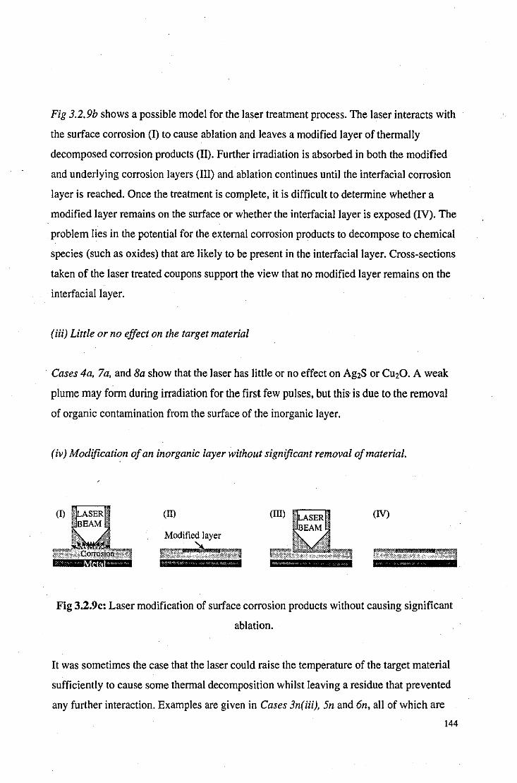
Fig 3.2.9b shows a possible model for the laser treatment process. The laser interacts with
the surface corrosion (I) to cause ablation and leaves a modified layer of thermally
decomposed corrosion products (II). Further irradiation is absorbed in both the modified
and underlying corrosion layers (III) and ablation continues until the interfacial corrosion
layer is reached. Once the treatment is complete, it is difficult to determine whether a
modified layer remains on the surface or whether the interfacial layer is exposed (IV). The
problem lies in the potential for the external corrosion products to decompose to chemical
species (such as oxides) that are likely to be present in the interfacial layer. Cross-sections
taken of the laser treated coupons support the view that no modified layer remains on the
interfacial layer.
(iii) Little or no effect on the target material
Cases 4a, 7a, and Ba show that the laser has little or no effect on Ag2S or CU20. A weak
plume may form during irradiation for the first few pulses, but this is due to the removal
of organic contamination from the surface of the inorganic layer.
(iv) Modification of an inorganic layer without significant removal of material.
(I) ff.IL".~"K I!II (IT) (N)
Modified layer
Fig 3.2.9c: Laser modification of surface corrosion products without causing significant
ablation.
It was sometimes the case that the laser could raise the temperature of the target material
sufficiently to cause some thermal decomposition whilst leaving a residue that prevented
any further interaction. Examples are given in Cases 3n(iii), 5n and 6n, all of which are
144
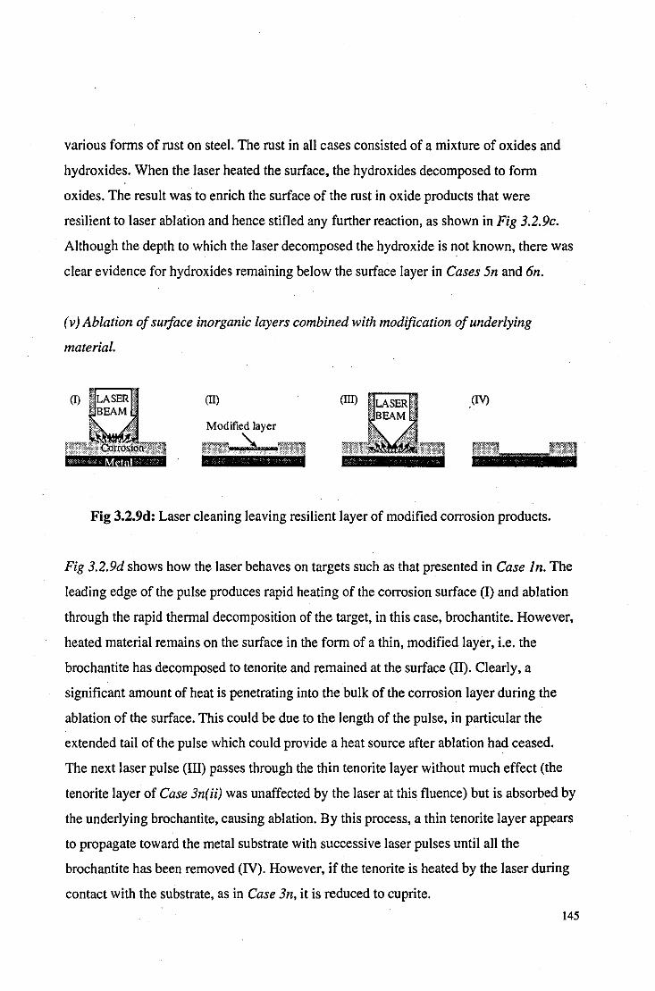
various fonns of rust on steel. The rust in all cases consisted of a mixture of oxides and
hydroxides. When the laser heated the surface, the hydroxides decomposed to fonn
oxides. The result was to enrich the surface of the rust in oxide products that were
resilient to laser ablation and hence stifled any further reaction, as shown in Fig 3.2.9c.
Although the depth to which the laser decomposed the hydroxide is not known, there was
clear evidence for hydroxides remaining below the surface layer in Cases 5n and 6n.
(v) Ablation of surface inorganic layers combined with modification of underlying
material.
(I) LASER (Il) (IV) BEAM
!i0
dtrOS10'IL'"n
Modified layer
~'\._.%,
Fig 3.2.9d: Laser cleaning leaving resilient layer of modified corrosion products.
Fig 3.2.9d shows how the laser behaves on targets such as that presented in Case In. The
leading edge of the pulse produces rapid heating of the corrosion surface (I) and ablation
through the rapid thennal decomposition of the target, in this case, brochantite. However,
heated material remains on the surface in the form of a thin, modified layer, i.e. the
brochantite has decomposed to tenorite and remained at the surface (11). Clearly, a
significant amount of heat is penetrating into the bulk of the corrosion layer during the
ablation of the surface. This could be due to the length of the pulse, in particular the
extended tail of the pulse which could provide a heat source after ablation had ceased.
The next laser pulse (III) passes through the thin tenorite layer without much effect (the
tenorite layer of Case 3n( ii) was unaffected by the laser at this fluence) but is absorbed by
the underlying brochantite, causing ablation. By this process, a thin tenorite layer appears
to propagate toward the metal substrate with successive laser pulses until all the
brochantite has been removed (IV). However, if the tenorite is heated by the laser during
contact with the substrate, as in Case 3n, it is reduced to cuprite.
145

Case Metal Chemical treatment or description Corrosion before laser Corrosion after laser F1uence substrate (J/em'),
pulses la copper Ig ofNH4CI, Ig ofC,H3CuO" 250 ml Uniform, blue layer on top of brown layer. Blue layer removed without 0.5,2-3
water, 10 min dip cycle for 48hrs, XRD: Cu(OH)CI and C,H3CuO,. damage to the underlying brown partially fanned. layer.
2a copper Ig ofNH,CI, Ig ofC,H3CuO" 250 ml Uniform, blue/green layer on top of red layer. Blue/green layer removed, red 2,1-2 water, 10 min dip cycle for 48hrs, XRD: Cu,CI(OH)3, C,H3CuO" CuC!. layer remained. XRD: CuC!. fanned.
3a copper Ig of NaCl, Ig ofCuS04.5H,O, Ig of Variable, blue and white, thick corrosion layer Blue/white layer removed, red 2,5-10 CuN03.3H,O, 250ml water, 10 min dip on top of red layer. XRD: Cu,CI(OHh, layer remained with some cycle for 72 hrs. Cu(OH)CI and CuC!. fibrillose black corrosion
products. XRD: CuCI and Cu,CI(OH),.
4a copper 5g of CuN03.5H,O in 25ml water, Thin, uniform, brown layer. XRD: Cu,O. No change. 4,10 boiled for 20mins.
5a bronze I g NaCl, I g CuS04.5H,O, I g Blue layer on top of dark brown layer. XRD: Blue layer was removed, brown 2,3-5 CuNO,.5H,O, 250ml water, IOmin dip CuCI,.3Cu(OH)" CuCI and Cu,CI(OH),. layer remained. XRD: no clear cycle for 72hrs. identification.
6a bronze Conc. HCI was left to evaporate from Thick, uniform pale torquoise layer on top of Uniform brown layer remained. 2,3-5 the surface of the coupon. . brown layer. XRD: (Cu,Zn),(OH),CI, XRD: CuCI and SnO,.
Cu,CI(OH)" B-ZnOHC!, 7a Sterling Coupon suspended above a solution of Very thin, dark grey tarnish. AES: copper and Very thin, dark grey tarnish. 2,2-3
silver 4g Na,S.9H,O in IOOml water at 60·C silver sulphides. AES: copper and silver for 2hrs. sulphides.
8a Silver Coupon suspended above a solution of Very thin, dark grey tarnish. AES: Ag,S. Very thin, dark grey tarnish. 2,2-3 4g Na,S.9H,O in 100m1 water at 6(fC AES: Ag,S. for 2hrs.
9a mild 4g NaCl, 250ml water, 10 min dip Uniform layer of orange/brown 'rust'. XRD: Metal substrate exposed, all 2,2-3 steel cycle for 24hrs. ~-FeOHCI, £-Fe,O, and FeOOH. corrosion removed.
Table 3.5: Summary of the laser treatment of artificially patinated metal coupons.
146

Case Metal Description Corrosion before laser Corrosion after laser Fluence substrate (J/cm2),
_pulses
In copper Copper roofing that had been replaced Uniform, pale green layer. XRD: Mostly Dull grey layer. XRD: Mostly 2, 10-20 after 30 years of exposure to the C.,.SO.(OH). and CU2CI(OH),. Also, CU20, CU20, some evidence for CU2S, atmosphere of a university campus. CuCl, CU2S0. and CU20(SO.).
2n copper Roman coin, patina has formed during Polished, dark green patina with brown Purple/ brown layer remained. 2,40-50 burial for a couple of thousand years. underlying layer. Chemical composition XRD: mostly CU20.
undetermined. 3n(i) brass Brass blowtorch, badly corroded but Uniform greenlblack layer with spurious All corrosion removed to 2,5-10
unknown history. Sample taken from occurrences of white spots. XRD: expose the dezincified, copper the body. (Cu,Znlz(OH),CI. coloured substrate.
3n(ii) brass Same blowtorch as above, sample Uniform, black layer on top of red. layer. Slight discoloration, dull grey 4,5-10 taken from the nozzle. XRD: CuO and CU20. layer remained. XRD CuO and
CU20. 3n(iii) steel Rusted handle of the blowtorch. Variable, orange/brown rust layer. XRD: ~- Rust was discoloured to a slate 2,5-10
FeO(OH) and Fe30 •. grey. XRD: y-Fe203 only. 4n brass A Liverbird sculpture that has been Uniform, pale green layer on top of which a Most corrosion was removed, a 2,20-30
exposed to the marine and urban thick black crust had formed spuriously and thin brown/purple layer environment of Liverpool for many underneath was a red layer. XRD (green): remained. XRD: Mostly CU20 years. Originally painted white, little Mostly C.,.SO.(OH). and Cu(OH)CI; XRD and ZnO. evidence of the paint remains. (black): Mostly (Cu,Zn)z(OH),CI and
CU2CI(OH),. 5n steel Rusted 'home-guard' helmet. Variable, friable orange/brown rust layer. Rust was discoloured to a slate 2,5-10
XRD: y-Fe,O" Fe,O., FeOOH and cx- grey. XRD: y-Fe203, Fe30., FeO(OH). FeOOH and cx-FeO(OH).
6n iron Extremely corroded nail from Thick, partially friable orangelbrown rust. Surface was blackened. 2,5-10 excavation site, almost none of the XRD: ~-FeOOH, FeOOH, ll-Fe20" E-Fe20,. original metal remained.
7n zinc Spoon. Thin blue/green corrosion on orange/brown All detectable traces of 2,3-5 alloy layer. XRD: Zn20 with possible presence of corrosion removed to leave
nickel nitrates and chlorides. exposed metal substrate.
Table 3.6: Summary of the laser treatment of naturally corroded and patinated metal objects.
147
3.3 Organic Coatings
Introduction
Organic coatings, in the form of paints and lacquers, are often applied to outdoor
sculpture as a form of protection from corrosion. However, the coatings themselves suffer
from degradation and inevitably breakdown creating an unsightly exterior that encourages
localised corrosion which may gradually spread over the whole sculpture, for example, on
the Liverbird in Case 4n. For this reason, it is important to investigate whether the laser is
successful at removing not only fresh organic coatings, but also aged and deteriorated
coatings.
Method
Surface analysis of the coatings could not be performed using XRD methods due to the
amorphous nature of the organic compounds. Also, due to electromagnetic noise from
surface charging effects, AES could not produce good quality spectra from organic
compounds. Therefore, the only method available to us for observing these coatings was
XPS. This technique could be used for quantitative elemental analysis and, with the use
cif high-resolution spectra, could identify the effects of ageing and weathering in the
coatings.
3.3.1 Fresh paint
Introduction
Laser cleaning tests on organic coatings were started with some simple tests on copper
coupons painted with a selection of different, common paints. Both modern (acrylic and
cellulose) and traditional (linseed oil based) paints were tried.
148

Method
The three copper (CI06, 99.85% pure) coupons were cleaned with wire-wool and rinsed
in high-purity acetone. Each was painted with a different black paint; one with cellulose
spray paint (two coats), one with Halford's 'Ford Black' acrylic spray paint (two coats),
and one with Winsor and Newton's 'carbon black' oil paint (one coat). The coupons were
left to dry for one week before laser cleaning.
Laser Cleaning
The laser was used at a fluence of 2J/cm2• All visible traces of paint were removed from
all three coupons, see Photo 3.3.1. Although the coupons at first appeared completely
stripped of paint within 5-10 pulses, the surface of the coupon felt as though some ofthe
coating still remained. If some paint remained on the surface, then it was in the form of a
very thin layer as there was no evidence of interference fringes or pigment and the copper
appeared clean to the eye. However, final confirmation of an organic layer remaining was
revealed using contact angles; values in the region of ninety degrees were observed
whereas an atomically clean surface would have provided a zero contact angle. Extending
the sub-plasma cleaning to more than 100 pulses did not eliminate the contact angle and,
therefore, the remaining organic layer.
Discussion
Although these three paints were all susceptible to laser ablation, they all left some
residue after laser-treatment at sub-plasma fluences that could not be removed, even after
subjection to excessive radiation. The origins and nature of these residues are explored in
more detail in Section 3.3.4.
149
3.3.2 Fresh lacquers
Introduction
Section 3.3.1 showed how a variety of paints were susceptible to laser ablation. From
these results alone, it is not obvious whether it was the pigment, the medium, or a
combination of the two that rendered the coatings susceptible to ablation. Lacquers are
essentiaIly paints that lack pigment and those tested here show that pigments are not
necessary for TEA CO2-laser ablation to be effective. The three lacquers tested in this
section are all commerciaIly available and speciaIly formulated for the protection of
outdoor sculpture and therefore have direct relevance to sculpture conservation.
Method
The three copper coupons were cleaned with wire-wool and rinsed in high-purity acetone.
Each was painted with a different type of lacquer; one with Incralac, an acrylic based
lacquer consisting of a solution of methyl methacrylate copolymer incorporating
benzotriazole and speciaIly formulated for the protection of copper and bronze (two
coats); one with Ercalene, a ceIlulose based lacquer with plasticizer for all metals,
particularly copper and brass (two coats); and one with Covalac, another lacquer speciaIly
formulated for the protection of copper and copper aIloys (two coats). The coupons were
left to dry for one week before laser cleaning.
Laser cleaned coupons
The laser was used at a fluence of 2J/cm2• AIl visible traces of lacquer were removed
from all three coupons, see Photo 3.3.2. As with the painted coupons, although the
coupons at first appeared completely stripped of paint, the surface of the coupon felt as
though some of the coating still remained and this was confirmed using contact angles;
values in the regions of ninety degrees were observed. Extending the sub-plasma cleaning
150

to more than 100 pulses did not eliminate the contact angle and, therefore, the remaining
organic layer.
Discussion
All the lacquers were susceptible to laser ablation but, like the paints, a very thin organic
layer remained after sub-plasma cleaning that could not be removed, even after excessive
laser irradiation. It would appear that the presence of pigment is not required for ablation
to occur and significant absorption occurs in the medium of the coating.
3.3.3 Aged and weathered coatings
Introduction
The results from sections 3.3.1 and 3.3.2 show that the laser has potential to remove fresh
organic coatings. However, with the exception of graffiti, fresh organic coatings rarely
require removal and it is only after a period of ageing and weathering that a coating has
degraded to an extent that it needs to be replaced. The effects of ageing usually alter the
absorption spectrum of the coating, as shown in Fig. 3.3.3a[231, as well as its chemical and
physical properties in general. It would be inaccurate to draw conclusions from results
obtained from the laser cleaning of fresh organic coatings and apply them to similar
coatings that have been outdoors for a number of years.
151

100
o+-~--~~--~~--~ 200 300 400 500
Wavelength (run)
Fig. 3.3.3a: The effect of ageing on the absorption spectrum of Incralac.
The investigation into aged coatings started with a series of attempts to use accelerated
ageing techniques to imitate the effects of many years of outdoor exposure within a few
weeks in the laboratory.
The first ageing experiments were tried on copper with an Incralac coating. Ultraviolet
fluorescent tubes were used that were active at 185 and 254nm, regions of high
absorpti vity in the Incralac absorption spectrum. The lacquered coupons were placed at
distances between 1 and 5cm from the UV source and solubility tests were performed at
daily intervals over a period of five days. UV exposure did not induce any significant
alteration in the solubility of Incralac in acetone although, after a period of five days, the
coupons placed closest to the UV-tubes had had all the lacquer removed. The UV
radiation appeared to be causing scission as opposed to crosslin)dng reactions in the
polymer coating and hence the experiment was abandoned and an alternative UV source
sought.
The second ageing experiment used a UV source that was active at 340nm, within the
emission spectra of solar radiation. The coupons were placed at 25mm from the UV -tubes
and exposed for a duration of 4 hrs, 1 day, 1 week, 1 month, and 3 months. After the 3
152

month test period. a slight decrease in solubility of the Incralac coating in acetone was
observed although the extent of deterioration fell far short of what would represent a
degraded coating on an outdoor sculpture.
After the accelerated ageing techniques proved to be unsuccessful and unrepresentative of
real ageing phenomena[241• it was decided to use naturally aged paint samples for
experiments. This meant losing a certain amount of knowledge as to the precise nature
and composition of the coating whilst retaining an authentically aged sample.
Method
Body-work samples were cut from a dilapidated automobile. They were painted both
sides. one side formed the external. exposed panel. and the other formed the internal.
protected panel ofthe car. The internal side (IS) had not been exposed to the ageing
effects of the weather and thus provided a control for the ageing effects observed on the
external side (ES). The paint thickness was measured for the ES and IS using a
micrometer and were found to be 8 and l3!1m respectively. the ES having a thicker
coating to provide additional protection. The number plate indicated the age of the vehicle
to be approximately ten years.
The body-work was cut into Icm2 squares of O.92mm thickness for laser treatment and
XPS analysis. Cross-sectional analysis revealed various off-white paint layers between
the metal substrate and the maroon coloured top-coat. Laser cleaning was performed at a
fluence of 2J/cm2.
XPS analysis was performed with a VG ESCALAB Mk I using AI Ku X-rays of energy
1486.6 e V at a residual pressure of 10.7 TOIT. Broad scan spectra were used to determine
atomic composition and high resolution spectra were used to provide more detailed
information on bond energies such that ageing effects could be identified. The estimated
depth of analysis was about IOnm and elements from Li through to U could be identified.
153

Surface compositions were determined after the subtraction of a Shirley-type background
spectra(25]. For the broad-scan spectra, three spectra of three one-minute scans were taken
for each of the samples and the results averaged. The high resolution spectra are
accumulations of twenty scans.
Pre-laser cleaned samples
The samples were cleaned with distilled water prior to analysis of the original surface.
Visual evidence of ageing was observed in the loss of gloss and slight yellowing of the
ES with respect to the IS surface. Both the ES and IS contain the same four elements, C,
0, N and Si (and, of course, a significant proportion of undetected H) as shown in Table
3.7. C and 0 are typical components of organic coatings. The O/C ratio in the ES coating
is significantly higher than the IS coating, indicative of oxidation and ageing. The
significant levels of N could also be part of the coating medium, or be present within
chromophore compounds that give the top-coat its maroon coloration (there was no
evidence of inorganic compounds to provide pigment). The Si could be present in the
form of polysiloxanes which are used as surfactants in modem paints.
Sample C (at%) o (at%) N (at%) Si (at%)
ES 65.6 24.2 6.8 3.5
IS 75.6 18.2 5.8 0.5
Table 3.7: Broad scan spectra of original paint layer.
High-resolution spectra support the evidence for weathering of the top-coat found using
the broad-scan spectra. Fig 3.3.3b and c show the Cls and Nls spectra respectively for
the top-coat samples. In Fig 3.3.3b, the most significant peak at 285eV represents CIH
and C/C bonds, the smaller peaks at higher bond energies are due to Clheteroatom bonds.
The smaller peak is far more pronounced in the ES than the IS samples due to the greater
abundance of functionalities such as C-N, C=N, C-O, C=O groups in the ES sample.
Similarly, Fig 3.3.3c shows the most significant peak at 39geV due to C/N bonds. There
154

is also a smaller peak for the ES sample at 403e V due to N/O bonds which is absent from
the IS sample. The 01s spectra for both samples showed a single, symmetrical peak
around 532.ge V ascribable mainly to C-O bonds with no appreciable difference between
the samples. Differences between samples due to ageing can be expected to be more
pronounced in the Cls and Nls spectra than in the Ols spectra where the relative changes
are smaller.
1600
ot-~~-.---r--.---~~--,
280 282 284 286 288 290 292 294
BE(oY)
Fig. 3.3.3b: Cl s spectra of weathered
(outside) and fresh (inside) top-coat.
Partial laser cleaning
400
Outside '--~'" Inside
o+--L.---.---.---~~r---' 396 394 398 400 402 404 406
BE(eV)
Fig. 3.3.3c: Nls spectra of weathered
(outside) and fresh (inside) top-coat.
The partial laser cleaning tests were performed by firing a single shot at the surface of the
sample. The composition of the surface of the remaining paint is shown in Table 3.8. The
partially cleaned surface had a faded appearance with respect to the original maroon
colour: this could be due to the roughening effect that the laser may produce, or due to the
decrease in chromophore species present, as shown by the N decrease in Table 3.8. The
decrease in Si can also be expected as the surfactant will be most concentrated at the
surface. There is a striking similarity between the two sides; both have almost identical
C/O ratios and there is no evidence of ageing from comparing the atomic compositions.
155

Sample C (al%) o (al%) N (al%) Si (al%)
ES 78.8 \9.\ 1.6 0.5
IS 78.5 \9.7 1.5 0.2
Table 3.8: Broad scan spectra of paint layer after single laser pulse.
The high resolution spectra shown in Fig 3.3.3d confirms the fact that the aged layer has
been removed to leave identical surfaces for the ES and IS samples. The ES and IS peaks
for the Cls spectra are clearly resolved and almost identical; the intermediate shift zone
of the ES spectra has decreased to the level of the IS spectra due to the removal of the
mildly oxidised species originating from ambient exposure.
2000
O+---~-'---r---'--'-~T--' 282 284 286 288 290 292 294 296
BE(eV)
Fig. 3.3.3d: Cls high·resolution spectra of fresh and aged paint layers after a single laser
pulse.
Discussion
The effects of ageing on the properties of the paint layer did not appear to significantly
influence the effectiveness of the laser cleaning process and all effects of ageing had been
removed after a single laser pulse. It is typical for ageing effects to alter the visible and
156
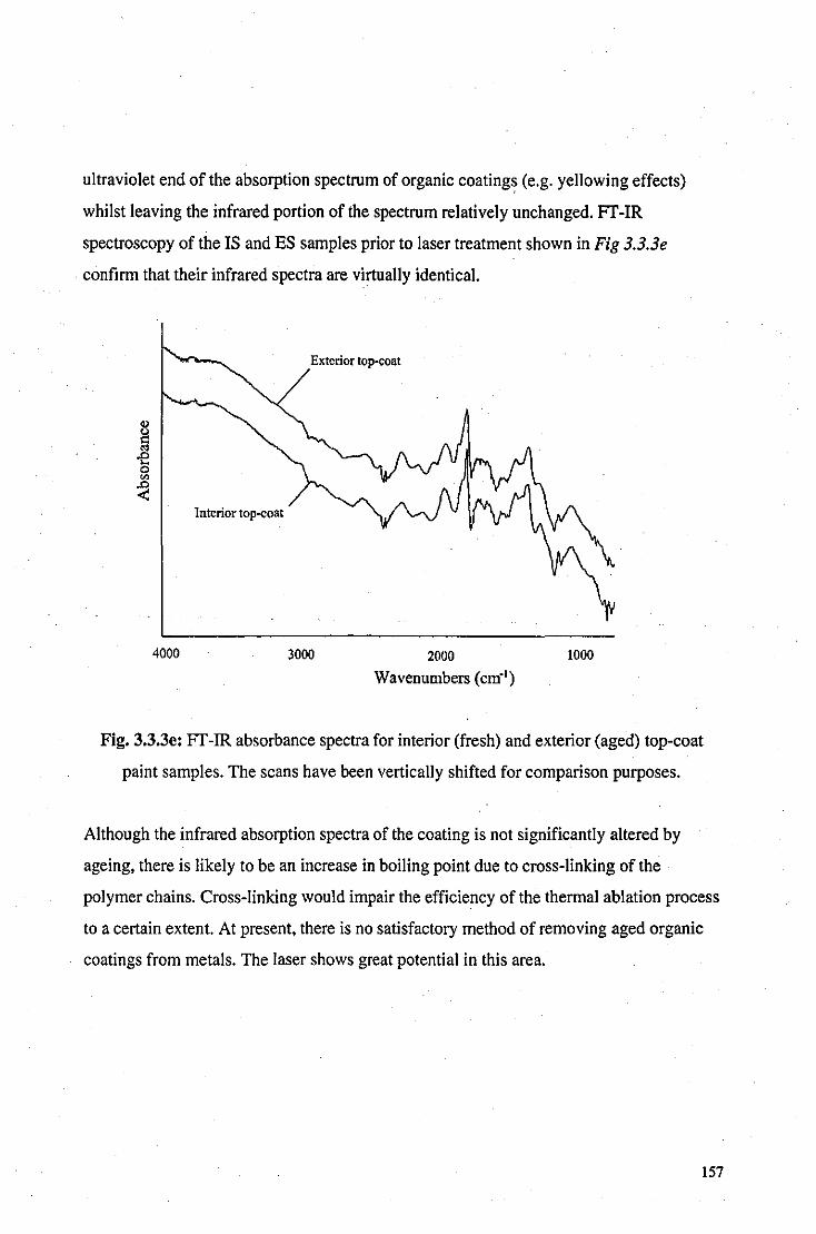
ultraviolet end of the absorption spectrum of organic coating~ (e.g. yellowing effects)
whilst leaving the infrared portion of the spectrum relatively unchanged. FT-IR
spectroscopy of the IS and ES samples prior to laser treatment shown in Fig 3.3.3e
confirm that their infrared spectra are virtually identical.
Interior top--coat
4000
Exterior top-coat
3000 2000
Wavenumbers (cm") 1000
Fig. 3.3.3e: FT-IR absorbance spectra for interior (fresh) and exterior (aged) top-coat
paint samples. The scans have been vertically shifted for comparison purposes.
Although the infrared absorption spectra of the coating is not significantly altered by
ageing. there is likely to be an increase in boiling point due to cross-linking of the
polymer chains. Cross-linking would impair the efficiency of the thermal ablation process
to a certain extent. At present. there is no satisfactory method of removing aged organic
coatings from metals. The laser shows great potential in this area.
157
3.3.4 Residual layers
Introduction
Although the laser has shown itself to be an efficient and effective remover of organic
coatings at sub-plasma fluences, the cleaned surface invariably shows a large contact
angle that is evidence of organic products remaining on the surface. Excessive cleaning at
sub-plasma fluences does not remove these compounds although they form a layer too
thin to be seen with the naked eye.
To investigate the nature of these residual layers and determine the reason as to why they
remain, XPS analysis was utilised on sub-plasma laser cleaned samples.
Method
The painted body-work samples from Section 3.3.3 were cleaned at sub-plasma fluences
until no more laser interaction took place. XPS analysis was performed using the same
machine and method described in the previous experiment; high resolution and broad
scan spectra were obtained. The full cleaning process required between fifteen and twenty
laser pulses at a fluence of 2J/cm2.
Results and Discussion
The fully cleaned samples had a dull grey appearance, see Photo 3.3.3g and 3.3.3h. The
metal substrate was mild steel with a zinc coating.
Table 3.9 (overleaf) shows the broad scan spectra of the samples. The high levels of Pare
due to the presence of a phosphate coating on the zinc substrate. These coatings are
applied for corrosion resistance and for their adhesive qualities[26J and can contain both
158

Zn and Sn anions[27]. As can be expected, the IS and ES samples show no significance
difference in their composition at this depth of analysis.
Sample C (al%) o (al%) N (al%) Si (al%) P (al%) Zn (al%) Sn (al%)
ES 59.4 25.9 2.4 - 8.1 3.0 1.2
IS 62.2 23.9 2.7 - 8.3 2.1 0.8
Table 3.9: Broad-scan spectra offully cleaned samples at sub-plasma fluences
The most striking observation from this analysis is that approximately 60% C exists on
the surface. Zinc and tin phosphate groups are typically of the form P03·· or P04·- such
that the majority, if not all, the oxygen remaining on the surface is likely to be associated
with the P and not the C. Thus, the carbon could only be associated with a very small
amount of Nor 0, insufficient for paint formulations. It would appear, from these results,
that the source of C is not from paint remaining on the surface. Fig 3.3.4a shows a high
resolution spectrum that enforces the results from the broad-scan spectrum.
2000
Partial laser
oL-~~----------~~-----BE (eV) (arbitrarily shifted)
Fig. 3.3.4a: High-resolution Cls spectra of part-cleaned paint and residue on fully
cl eaned surface.
159
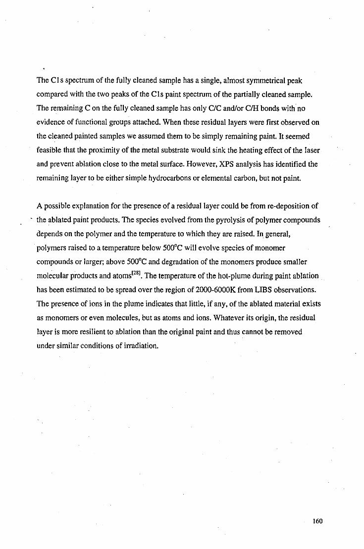
The Cl s spectrum of the fully cleaned sample has a single, almost symmetrical peak
compared with the two peaks of the Cls paint spectrum of the partially cleaned sample.
The remaining C on the fully cleaned sample has only C/C and/or CIH bonds with no
evidence of functional groups attached. When these residual layers were first observed on
the cleaned painted samples we assumed them to be simply remaining paint. It seemed
feasible that the proximity of the metal substrate would sink the heating effect of the laser
and prevent ablation close to the metal surface. However, XPS analysis has identified the
remaining layer to be either simple hydrocarbons or elemental carbon, but not paint.
A possible explanation for the presence of a residual layer could be from re-deposition of
the ablated paint products. The species evolved from the pyrolysis of polymer compounds
depends on the polymer and the temperature to which they are raised. In general,
polymers raised to a temperature below 500°C will evolve species of monomer
compounds or larger; above 500°C and degradation of the monomers produce smaller
molecular products and atoms[281. The temperature of the hot-plume during paint ablation
has been estimated to be spread over the region of 2000-6000K from LIDS observations.
The presence of ions in the plume indicates that little, if any, of the ablated material exists
as monomers or even molecules, but as atoms and ions. Whatever its origin, the residual
layer is more resilient to ablation than the original paint and thus cannot be removed
under similar conditions of irradiation.
160

References
[I] Naylor, A., 'Developments in the conservation of coloured metal surface treatments to outdoor sculpture', unpublished work. [2] Hughes, R., and Rowe, M., 'The Colouring, Bronzing and Patination of Metals', Thames and Hudson, London ,(1991). [3] Tennent, H. N. and Baird, T., 'The identification of acetate efflorescence on bronze antiquities stored in wooden cabinets', The Conservator, 16,(1992),39-43. (4) Livingston, R. A., 'Influence of the environment on the patina of the Statue of Liberty', Environ. Sci. Technol., Vol. 25, No. 8, (1991),1400-8. [5] Sochja, J., 'Oxide coating in the conservation of metal monuments: The column of King Sigismundus m Waza in Warsaw', Studies in Conservation, 25,(1980),14-8. (6) Morales, J., Fernandez, G. T., Esparaza, P., Gonzalez, S., Salvarezza, R. C., Arvia, J., 'A comparative study of the passivation and localised corrosion of alpha, beta, and alpha + beta brass in borate buffer solutions containing sodium chloride I. Electrochemical data', Corrosion Science, 37(2), (1995), 213-31. (7) Opila, R. L., 'Copper patinas - an investigation by auger electron spectroscopy', Corros. Sci., 27, (1987), 685. (8) Sneed, M. C., Maynard, J. L., Brasted, R. C., from Comprehensive Inorganic Chemistry Vol. H, D. Van Nostrand Company Inc., London, (1954), 142-3. (9) Biasini, V., Cristoferi, E.:A study of the corrosion products on sixteenth and seventeenth century armour from the Ravenna National Museum', Studies in Conservation, 40, (1995), 250-6. [10] Sjorgren, A., and Buchwald, V. F.:Hydrogen plasma reduction in the D.C. mode for the conservation of iron meteorites and antiquities', Studies in Conservation 36, (1991),161-71. [11] Zucchi, F., 'Beta-iron oxide hydroxide formation in localised active corrosion of iron artifacts' in Corrosion and Metal Artifacts, NBS Special Publication 479 (1977), 103-5. (12) Patscheider, J., Veprek, S.,'Application of low-pressure hydrogen plasma to the conservation of ancient iron artifacts', Studies in Conservation, 31, (1986), 29-37. [13] Keller, P.:Vorkommen, Einstehung und Phaseunwandlung von Beta-FeOOH in Rost', Werk U. Korr., 20, (1969), 102. [14] Vernon, W.H.J, and Whitby, L.:The open-air corrosion of copper. A chemical study of the surface patina', J. Inst of Metals, 42, (1929), 181-196. [15] Livingston, R. A., 'Influence of the environment on the patina of the statue of liberty', Environmental Science and Technology, 25(8), 1991, 1400-8. [16] Wingerson, L., 'America cleans up Liberty', New Scientist, (25 Dec 1986), 31-35. (17) Lins, A.:Outdoor Bronzes: Some Basic Metallurgical Considerations: from Sculptural Monuments in an Outdoor Environment, Ed, V.N. Naude, Pennsylvania Academy of Fine Arts, Philadelphia, (1985), 9-20. (18) Nielsen, N. A., Mater. Perform., 23(4), (1984),78. (19) Weast, R.C., (Chief Bd.), from CRC handbook of Chemistry and Physics, 70th Bd., CRC Press Inc., Florida, (1989). [20] from Newarke Housing Museums. (21) Fabrizi, M., Ganiaris, H., Tarling, S., Scott, D.A., 'The occurence of sampleite, a complex copper phosphate, as a corrosion product on copper alloys objects from Memphis, Egypt', Studies in Conservation, 34, (1989), 45-5\. [22] Steve Newman, private communication. [23] Erhardt, D, Veloz, N. F., 'The durability of Incralac: Examination of a ten year old treatment, ICOM 1984 Preprints of the 7th Triennial Meeting, 84.22.1-3. [24] Skerry, B. S. and Simpson, C. H., 'Acclerated test method for assessing corrosion and weathering of paints for atmospheric corrosion control', Corrosion, 49(8), (1993), 663-74. [25] Shirley, D. A., Physics Review B, 5, (1972), 4709. [26] Weng, D., Jokiel, P., Vebleis, A., Boehni, H., 'Corrosion and protection characteristics of zinc and manganese phosphate coatings', Surface Science and Technology, 88, (1996),147-56. [27] Nomura, K., Ujihira, Y., Kojima, R., Yoshida, M., 'Characterisation of converted tin phosphate coating on iron and steel by conversion Moessbauer spectroscopy (CEMS)" Journal of Material Science, 27, (1992), 2449-57.
161

[28] Madorsky, S. L., from Thermal Degradation of Organic Polymers, John Wiley and Sons, Inc. London, (1964) 3.
162
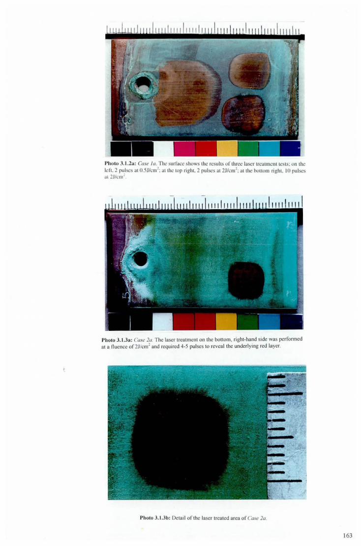
Photo 3.1.2a: Case la. nl~ ",urfacc shows Ihe res ults of threl.! laser 1n;;.I tmcnttcs ts: on the lefl. 2 pulse", !.It 1).5Jlcm!: ;.I t the lOp righl. 2 pulses at 2J/cm2
: al the botl om rig ht. 10 pulses :It 2J/cm;
PholO 3.1.3a: Case la. The laser treatment on the bollom, right-hand side was ~rfonned a1 a fluence of2J/cm~ and required 4-5 pu lses to reveal the underlying red layer.
Photo 3.1.3b: Detail of the laser treated area of Case l a
163

PholO 3. 1 AfI: Co.\e 30. The laser treatment on the bottom, fight-hand side was performed at a nuencc of 2J/cm 2 and required 9- 10 pulses to revl!a ltht! underlYlIlg red layer
Photo 3.1 .4b: Detai l of the laser treated area of ( ·ase 30.
PllolO 3. 1 04 (': Cross-section thro ugh the copper coupon from Cllse 3a. The left -hand side shows Ihe untreated corroSIOn layers, the right-hand side the laser treated area. The red interfacial layer is clearly visible on both sides and represents the limit o f the clean ing proceSs
164
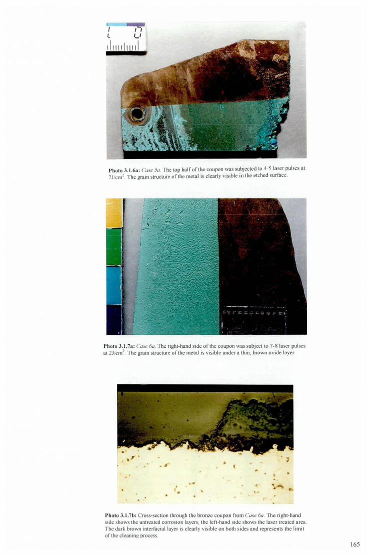
I I ~ l U
d 11111 I11 d
1)11 010 3. 1.6:1 : ("ase Sa, The lOp half of the coupon was subjected 10 4-5 laser pulses al 2J/cn{ The grai n structure of the metal is clearly visible in the e tched surface.
I'holo 3.1.7a: Case 6lJ. The right-hand side of lhe coupon was subjccllO 7-8 laser pul ses 31 2J/cm1
, The grain structure of the metal is visib le under a thin, brown ox ide laye r.
, " " . • I
. -• ' . '
• •
, .
• ,
Photo 3.1. 7b: Cross-section through the bronze coupon from ("ase 6u. The ri gh t-hand Side shows the umrealcd corrOSion layers, the left-hand SIde shows the laser treated area. The dark brown interfacial layer is clearly visible on both sides and represents the limit of the cleaning process.
165

Photo 3. 1.1 Oa : C(I"e 911. The mild steel surface has been exposed after 2-3 laser pulses at
2J/cm1.
"("(l {\]
Photo 3.2. h : ('ose Ill. From len to right is the untreated coupon; the blackening errect after two, 2J/cm1 laser pulses; the full y treated sample after 10-1 5 pulses at 2J/cm2
: and the fully treated sample after a beeswax coating has been appl ied.
Photo 3.2. 1 b: Cross-secti on taken th rough the roofing or Case Ill . There is no visible Interfacml layer between the green corrosion and the copper substrale.
166
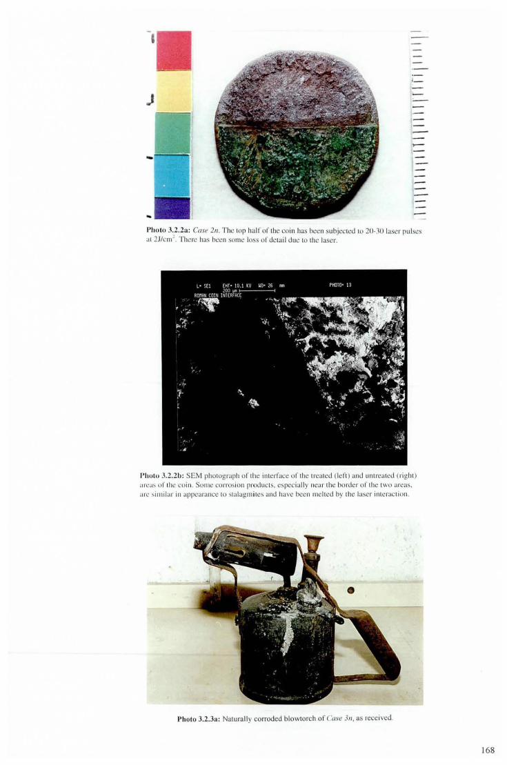
I
,-J
c
Photo 3.2. 2~1: Cast' 211 . The top half of I h~ co in has hecn subjected to 20-30 laser pu lses .11 2Jk ml. Thr.:n! has ncCIl sOllle lo!>s of dctail duI.! (0 the lascr.
I'hu tu 3.2.2h: SENI pholograph of the interface o f the treated ( left) and ullIrc:llcd (n ghl ) : 11\ : :1'" of I hI.! coin . SOIl IC cOfl'O:. ioll products. c:-. pecially Ilc ar the border of the lWO areas.
arc ... imi lar in appl.!:lI':tncc 10 ... lal:lgll1i IC~ ami have bee n mc hed by the la~cr interac tiulI.
Pholo 3.2.3:1: Naturally corroded blowtorch or ease 311, as recei ved.
168

l
Photo 3.2.3b: The blowlorch after laser tfemment at a nuence of2J/cm2, Pan or lhe steel
bracket and head-piece have been removed for surface analysis.
I'holo 3.2.3c: The untreated needle valve rrom the blowtorch in O.l.\e 311.
1'11\11111 11 I)holo 3.2.3d: The needle valve after laser Irealmcnl at a nuence of2J/cm2 Note how the laser has penetrated iOlo the thread and clarified the embossed wflung.
169

-I --~ --...... ---1 -
I'iwttl J.2.3c: Uru l'r.:<Ltl.!d !)ampk taken from thl.! b towlorch hc .. d in Case ] 11 . Some o f the powdery black laycr fell away : I!) the sample wa.') removed 10 reveal an underlyi ng red laye r.
• IJ
Pho to 3.2.31': Ll'il.:r Ircatrllcnt o f Ihe surfacl! of thl! hlowlorch hr..:ad ;.LI a llucllI'::c o f 4J/cm2
wll idl has :lhr.!l'!.::d the r.!oiorati(l ll .
------- , --------
I)holo 3.2.3g; Untreated sample taken rrom the blowtorch bracket in Ct,se 311,
l70

------- ' -------
l)holO 3.2.3 h: Lase r treatment of the blowlOrch bracket at a nuencc of2J/cm2 caused a change in co loration.
•
Photo 3.2.3 i: A c ross-secti on through the blowtorch body in Case 311, T he right-hand side is unt reated and Ihe left -hand side has been laser treated. There is no evidence of a remaini ng corrosion layer on the laser-treated side, and the metal surface has retai ned ils ro ughness wi lh no evidence of melt ing.
PI,IOIO 3.2.4a: Th~ grccll palinalion. the whilc p:..tim. and Ihe black crust an.:. all apparcllI in Ih ls phOtograph of Ihl! Livcrhird's tail-fl!:l thcrs. -nil! dark hrown area in the (;cnlrc has bcl.!ll
laser dC:lncd and also hCl!swaxcd. Thl! brass area 10 the richl is where a samnlc was
171

Pho to 3.2.4h: ('{lst! .JII, as rece ived. Laser trcatmelll was inlliah:d on the sheltered region of the tai l-fea thers.
l)holO J.2.4c: A larger area of Ircatmenl , thi s lime without any beeswax coating. If thiS photograph is compared wi th 1)11010 3.2.4(/ . there has been a clear improvement of surface de fin ition.
I' holo 3.2Ad: A cross-section ta ke n from one or the claws of the Live rbird. The bottom of the photograph shows the brass substrate, on top of which the red layer, then green luyer, then black layer can be di stinguished
172

Photo 3.2.5a : 'use 511. The untreated , rusted surface is shown on the right, the laser treated surface in the middle, and the laser treated surface after a beeswax coating has been applied, on the left
Photo 3.2.5b: Case 5". The same helmet shown from above.
I)holo 3.2.6a: The rusted nail from Case 611 The shape of the anginal surface is completely obscured by corrosion products.
1I11 \ 1111\1111 \ I 111\11 11 \ I1I I IIII I 11
Photo 3.2.6b: Laser treatment of the nail al a nuence of2J/cm2 caused blackening of the corrosion products.

Photo 3.2.7a: The bowl of lhe untreated spoon from Case 7"
Photo 3.2.7b: The corrosion was removed from the spoon after j ust a couple of pulses at 2J/cm2
. The source of the disco loration was not identified.
I'holo 3.2.8a: Case 8" Lcft·side shows laser treatment after 5·10 pu lses 01 1 3-4J/cm?
173
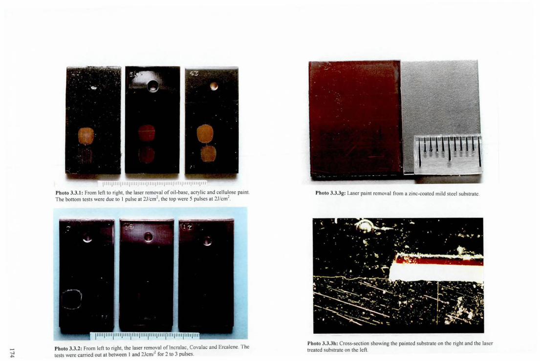
I)hoto 3.3.1: From left to right, the laser removal of oil-base, acryli c and ce llulose pamt The bottom tests were due to 1 pul se at 2J/cm l
, the lOp were 5 pu lses at 2J/cm2.
Photo 3.3.2: From left to ri ght, the laser removal oflncmlae, Covalac and Ercalene. The tests were earned out at between I and 2Jcmr for 2 to 3 pulses.
Photo 3.3.3g: Laser paint remova l from a zinc-coated mild steel substrnte.
Photo 3.3.3h: Cross-section showing the painted substrate on the right and the laser treated substmte on the left.

CHAPTER 4
Plasma Laser Cleaning and Treatment
The use of the TEA-C02 laser at plasma-inducing fluences offered another facet to the
laser's cleaning and treatment ability. Research into plasma laser cleaning was driven by
the need for an effective, environmentally-friendly alternative to the use of volatile
organic solvents for the pretreatment of metals prior to adhesive bonding: this will be
explained in more detail in Section 4.2 where the effect of the plasma on specific metal
targets is investigated.
4.1 Plasma Effects
TEA C02-laser treatment of materials using a fluence in excess of 4Jcm-2 can partially
ionise the air directly above the target sample. The resultant plasma will invariably
interact with the surface of the material and therefore its presence is unwanted in the field
of metal conservation. However, the effects of the plasma can be beneficial when extreme
surface cleanliness is required and slight modification of the metal substrate is not so
important or may even be desirable.
4.1.1 Plasma cleaning mechanisms
Plasma-fluence radiation incident on a metal surface will clean the surface in two steps:-
(i) As described in section 2.4.1, the laser pulse couples with the surface of the metal for
approximately IOns prior to the formation of the plasma. During this period, there is no
shielding of the surface to the incident radiation and there is some ablation of surface I
contamination by direct interaction with the laser pulse.
175

(ii) At some point on the leading edge of the laser pul se, ionisation will be initiated and a
plasma wilJ rapidly form. Once formed, practicalJy alJ the subsequent laser pulse is
shielded from the target surface and is absorbed by the plasma itself. There is no further
direct coupling of the laser radiation with the surfac~ for the duration of the pulse. The
plasma forms as a bright blue/white spark that re-radiates energy in the blue/near-UV
portion of the spectrum. The plasma emits a significant amount of ionising radiation that
can remove organic compounds from the surface of the metal. Metals are generalJy
absorbing in this region of the spectrum and may experience significant heating through
exposure to the plasma. Also, ionised atoms of air and blow-off material may be incident
on, and interact with, the surface of the metal.
4.1.2 Initiating and sustaining plasma
Creation of initial electrons
There are several mechanisms involved with initiating and sustaining plasma. In the first
instance, electrons have to be produced from the ionisation of matter. Single photons of
visible or infrared radiation have insufficient energy to ionise most gases. Hence, multi
photon ionisation (MPI) has been proposed as a possible mechanism for initial electron
production. For example, photons from an Nd:YAG laser have a wavelength of 1060nm
and energy of 1.2e V and thus the MPI of N2 would require the absorption of lO such
electrons. Baravian et al[l] have shown MPI to be an acceptable model for plasma
initiation in this case. However, CO2-laser photons have one tenth the energy of those of
Nd:YAG lasers; more than lOO of the 0.12eV photons from COrlasers would be required
to ionise most gas atoms (ionisation potentials for most gases exceed lOeV). The high
number of impacts required for MPI at C02-laser wavelengths are highly improbable and
the mechanism does not sufficiently explain the low breakdown thresholds in pulsed
C02-laser irradiated gases[2].
176
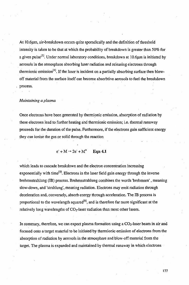
At 1O.6I!m, air-breakdown occurs quite sporadicalJy and the definition of threshold
intensity is taken to be that at which the probability of breakdown is greater than 50% for
a given pulse[3]. Under normal laboratory conditions, breakdown at 10.6/lm is initiated by
aerosols in the atmosphere absorbing laser radiation and releasing electrons through
thermionic emission[4]. If the laser is incident on a partialJy absorbing surface then blow
off material from the surface itself can become absorbtive aerosols to fuel the breakdown
process.
Maintaining a plasma
Once electrons have been generated by thermionic emission, absorption of radiation by
these electrons lead to further heating and thermionic emission; i.e. thermal runaway
proceeds for the duration of the pulse. Furthermore, if the electrons gain sufficient energy
they can ionise the gas ,Or solid through the reaction
e' + M -> 2e' + M+ Eqn 4.1
which leads to cascade breakdown and the electron concentration increasing
exponentialJy with timerS]. Electrons in the laser field gain energy through the inverse
brehmsstrahlung (IB) process. Brehmsstrahlung combines the words 'brehmsen' , meaning
slow-down, and 'strahlung', meaning radiation. Electrons may emit radiation through
deceleration and, conversely, absorb energy through acceleration. The IB process is
proportional to the wavelength squared[6], and is therefore far more significant at the
relatively long wavelengths of C02-laser radiation than most other lasers.
In summary, therefore, we can expect plasma formation using a C02-laser beam in air and
focused onto a target material to be initiated by thermionic emission of electrons from the
absorption of radiation by aerosols in the atmosphere and blow-off material from the
target. The plasma is expanded and maintained by thermal runaway in which electrons
177

gain energy through the IB process and ionise blow-off material, aerosol matter and
transport medium gases, which leads to cascade breakdown.
Factors affecting plasma threshold
For a TEA COr laser focused above a metal target, the following factors can influence the
plasma threshold fluence.
(i) 'Air quality': breakdown thresholds can be increased many fold by removal of aerosol
particles from air17J, especially when the target is clean and highly reflective so as not to
contribute blow-off material to the process. The size, abundance and optical-properties of
the aerosols will also influence the breakdown threshold. The air quality can be expected
to decrease during laser cleaning as blow-off material contributes to the level of aerosols
in the immediate surroundings.
(ii) Target material: clean metals are generally highly reflective of CO2-laser radiation,
although some may suffer surface vaporisation at high fluences. Hence, metals
susceptible to laser ablation may contribute matter to the breakdown process. The
surfaces of metals will almost invariably possess some degree of surface contamination
through exposure to adventitious material (e.g. hydrocarbons) frorri the air and this
material may be vaporised and contribute to the breakdown process. Corroded and coated
metals are liable to contribute a large amount of blow-off material during laser irradiation
at significantly lower threshold levels than clean metals. Also, metals generally reflect
such a large proportion of incident radiation that the region directly above the surface of
the metal effectively doubles in flux density due to overlap of both incident and reflected
beams.
(iii) Focusing lens: the laser beam focused by a lens with a long focal length will form a
radiation field of a more acute angle than that of a lens with a short focal length. Hence,
for a given fluence, the region directly above the target material will have a higher flux
178

density for the weaker lens and will therefore be more conducive to plasma formation.
However. the minimum spot-size for coherent radiation in a given focal system with a
circular aperture is the Airy disk. given by[8]
R - 1.22fIJD Eqn.4.2
where R is the spot radius. f the focal length of the lens. t. the wavelength of laser
radiation and D the diameter of the aperture. Hence. for a given system. the more
powerful lens can focus the beam to a smaller spot-size and thus provide a higher
obtainable f1uence. Taking these two considerations into account. the more powerful the
lens. the higher the possible incident f1uence and the earlier in the laser pulse breakdown
could be initiated. However. once breakdown had been initiated. the less powerful lens
system would provide a greater flux to sustain the plasma for the remainder of the pulse.
From these two opposing factors it is not clear whether a long or short focal length is
desirable for efficient plasma production and detailed experimental observations would
be required to assess the effects focal length has on plasma formation.
4.1.3 Plasma observations
Laser-induced breakdown can be defined as the generation. by a laser pulse. of a highly
ionised gas (plasma). When breakdown occurs in air. it usually takes the form of a bright
blue/white spark and should not be confused with the hot plume of gas and blow-off
material that forms during sub-plasma irradiation. Photo 2.4.2h (see Chapter 2) shows a
time-exposure photograph of the breakdown above a copper-roofing target. The plasma
has started to form at two different sites and is surrounded by the hot plume of heated
blow-off material.
The distinction between the plasma and hot-plume can also be seen using Laser Induced
Breakdown Spectroscopy (LIDS). Fig 3.2.1c (see Chapter 3) shows 3 spectra from using
the laser at different f1uences. At the lowest f1uence, no peaks are detected and therefore
179

there is no evidence for ionised matter. At this fluence, the plume had an orange/yellow
appearance. At a higher fluence, several peaks are detected although the appearance of the
plume has not visibly altered. The peaks that are observed at this fluence are due to the
ionised blow-off material and not air-breakdown which supports the theory that the
electrons are initially produced by the thermionic emission of heated aerosols (in this
case, from the blow-off material) and not directly from ionisation of the air. The highest
fluence produces a spectra with many peaks from ionised blow-off material, and nitrogen
and oxygen from the air and is accompanied by the characteristic blue/white flash.
4.1.4 Plasma cleaning
The surface interaction of the laser just below the plasma fluence appears to vary
significantly from that of the laser just above the plasma fluence and it would appear that
it was the plasma itself, as opposed to the slight increase in fluence, that was responsible
,for the differences.
In section 3.3.4 it was discussed how metal coupons with organic coatings on them still
produced a large contact angle after prolonged irradiation with sub-plasma laser pulses.
Further experiments on the same coupons revealed that the contact angle could be
reduced to zero if the intensity of the radiation was increased above the plasma threshold.
Even a sub-monolayer of organic contamination will produce an observable contact
angle[9], hence, cleaning at plasma fluences appears to remove all traces of organic
compounds.
Laboratory exposure tests
To illustrate the effectiveness of plasma cleaning and the influence of organic '
contamination on contact angles, a simple laser cleaning and laboratory exposure test was
performed. Coupons of degreased mild steel were subjected to laser pulses, each
exceeding the plasma threshold. The contact angle was measured throughout the
180

treatment, as shown in Fig 4.I.4a. It is interesting to note that even after a thorough
double-degreasing there is still sufficient adsorbed or strongly bonded carbon-based
molecules on the surface to give a contact angle of almost 70°. The contact angle initially
decreases rapidly with laser treatment and is reduced to 10° after just five pulses.
However, at this point a plateaux is reached and it requires another 10 pulses to reduce
the contact angle to zero, at which point the surface can be considered atomically clean
and completely free of organic contamination. AES was carried out to confirm that the
surface could be considered atomically clean after 15 pulses.
80
70
ISO too -l40
~30 E § 20
10
0 0
Variation of Contact Angle with Laser Pulses
5 10
Laser Pulses
15 20
Fig. 4.1.4a: Decrease in contact angle with laser pulses exceeding the plasma threshold
incident on a degreased mild steel target.
Laboratory exposure tests were performed with coupons of mild steel, laser-cleaned with
20 pulses above the plasma threshold such that a zero contact angle was measured at the
surface. The coupons were then left exposed to the atmosphere of the laboratory and the
contact angles measured over a 24hr period using triply distilled water, as shown in Fig
4.I.4h.
181

50 45
40
i 35 \!! Z' 30 :2. 25 .!! ~ 20 ..: 15
~ 10
:3 5
Variation In Contact Angle with Exposure to Laboratory AtlTK)Sphere
o~------~------__ ------__ ------__ ----~ .5 1 10 100 1000 10000
Exposure Time (m Ins)
Fig 4.1.4b: Variation in contact angle with time during the laboratory exposure of laser
cleaned mild steel coupon.
There is a clear logarithmic relationship between the contact angle and the exposure time
with significant contamination levels even after just a minute of exposure ..
Plasma spectroscopy
Pla8l11a on HOG during cleaning
Pullet
I~~~~~§~~~~~~~§~~~~~ -, -2 -3 -4
-'a ~... -2.
~ ~ ~ ~ ~ m ~ § ~ ~ ~ ~ ~ ~ ~ ~ ~ ~ Wavelength (nm)
Fig. 4.1.4c: LIBS spectra of plasma during laser treatment of degreased HOG at a fluence
of 12Jcm·2• After 10 pulses, only Nand 0 peaks remain. Spectra have been shifted
vertically for comparison.
182

The laser required several pulses above the plasma threshold fluence to achieve zero
contact angle. It was possible to use LIBS to observe the cleaning effect of the laser at
plasma fluences. Oegreased hot-dip galvanised (HOG) mild steel coupons were subjecte~
to laser pulses above the plasma threshold. Figs 4.1.4c and 4.1.4d show the spectra
obtained after a given number of pulses at 12Jcm-2 and 6Jcm-2 respectively.
Plasma on HOG during laser cleaning
Pulses
-1 -2 -. -. -. -10 -20
~ ~ ~ ; ~ ~ ~ ~ m ~ ~ ~ ~ ~ ~ § ~ ~ ~ Wavelength (nm)
Fig. 4.1.4d: LIDS spectra of plasma during Jaser treatment of degreased HOG at a fluence
of 6Jcm-2• After 10 pulses, only Nand 0 peaks remain. Spectra have been vertically
shifted for comparison.
In both cases, the first laser pulse produces a plasma of greatest intensity and also the
largest number of peaks. The second laser pulse has a similar appearance to the first,
although some ofthe peaks have decreased significantly in size. The gradual elimination
of these peaks continues with an increasing number of pulses until both examples exhibit
consistent spectra after \0 and 20 pulses.
It appears that a clean metal surface remains after 10 and 20 pulses, and that the peaks
that are still evident are due to ionisation of oxygen and nitrogen in the air. No evidence
of zinc, the metal substrate, is observed in any of the spectra. When the initial spectra are
compared with the final spectra, it is simple to identify the peaks which exist due to
surface contamination and observe their decline throughout the treatment process.
183

The intensity of the plasma on the whole decreases throughout the cleaning process, this
is especially apparent when the first pulse is compared to the second. The surface
contamination provides blow-off material for thermionic emission of electrons and thus
expedites the initiation of the plasma. Hence, there appears to be a direct correlation
between the intensity of the plasma radiation and the cleanliness of the surface.
4.2 Cleaning and adhesion
Introduction
There are several advantages of using adhesives on metals compared with other, more
conventional methods of joining, such as brazing, welding, riveting and welding. These
include: the ability to join thin sheets efficiently; improvements in stress distribution in
the joint; increases in design flexibility; and also, adhesives are often the most convenient
and cost effective technique[I01.
The failure of joints incorporating metal adherends can often be attributed to inadequate
surface preparation[ll] and suitable surface pretreatment is an 'extremely important
factor,[I21 in creating reliable, durable joints. During the manufacture of metals there is
plenty of opportunity for contamination of the surface with various organic and inorganic
substances[l31 such that the surface will typically resemble that shown in Fig 4.2a; even
cleaned metal surfaces will pick up contamination from the atmosphere if left exposed,
see section 4.1.4. The removal of surface contamination, loosely bound oxides etc., will
usually ensure a joint with a high initial bond strength. However, to produce a highly
durable joint will usually require the presence of an adherent, passive oxide layer on the
surface of the adherend which is receptive to the adhesive and have good environmental
resistance[ 141.
184

~.~.~ :' .. ~. ~ ·;"0;.t ;.~~~;ei!~!:~rg~~i~'··.:[t.t:J~.~·~ ... :.···t.tZ
Polnr
Fig. 4.2a: Adsorbed layers on a metal surface, typically to a depth of 1O-300nm.
A wide range of surface treatments are available for metal adhesion which procure some
or all of the aforementioned features to facilitate a strong and durable bond. These include
mechanical treatments, e.g. abrasion or grit-blasting; chemical treatments, e.g. chromic
sulfuric acid etching or conversion coating; and electrochemical treatments, e.g. chromic
or phosphoric acid anodising. It is widely accepted that the most effective surface
treatments for aluminium are chromic and phosphoric acid anodising for a broad range of
exposure conditions[l5-18J. Although there can be no doubt as to the effectiveness of these
treatments, their application can be complicated, involving many stages and invariably
produce excessive quantities of highly toxic effluent.
Recently, a new method of surface treatment has been developed that involves the use of
high powered laser radiation. Lasers can alter the chemical properties of the surface, and
hence influence the interaction of the adhesive with the adherend and also the adherend's
resistance to environmental degradation. Lasers can also alter the surface morphology,
effecting the degree of physical interlocking between adhesive and adherend. To date,
most work has concentrated on the use of excimer lasers to clean the surface and increase
its roughness and porosity, thereby enabling a higher degree of mechanical interlocking
and hence adhesion[l9.20J_ The following investigation into metal surface pretreatments
using the TEA CO2-laser combines the ablative effect ofthe laser incident on the surface
of the metal together with the subsequent formation of a plasma above the surface.
185

4.2.1 Aluminium
Introduction
In order to investigate the potential for TEA C02-lasers to be used as a pretreatment
process for metals in adhesive bonding, a comparative study was carried out comparing
this with a number of established, effective pretreatment processes on aluminium.
Aluminium was chosen because this metal is already widely used with adhesives, in
particular, in the aerospace industry where it has lead to advantages that include 'weight
saving, improved aerodynamics, and reduced cost of manufacture,[21J. In this case, laser
treatment was compared with three other treatment methods as detailed below. Bonded
joints were created with each pretreatment method using a standard adhesive and tested to
measure the initial joint strength and stressed durability performance.
Experimental
Aluminium 5251 alloy (nominal composition by weight, 0.1-0.5% Mn, 1.7-2.4% Mg,
0.15% Cu, 0.4% Si, 0.5% Fe, Al balance) was cut into coupons measuring 25mm x
60mm by 2mm thickness. The coupons were subjected to the following treatments:
(i) Degrease only: achieved by two separate iOmin ultrasonic submersions in 'Super
Purity' acetone. This process is repeated as part of the treatments (ii) and (iii) below.
(ii) Degrease plus laser treatment: laser treatment was performed at an energy density of
approximately 20Jcm·2. The laser was rastered over the surface such that each point
received 5 pulses each. This was sufficient to reduce the contact angle to zero and hence
produce a surface free from organic contamination. Joints were assembled within 30
seconds of laser treatment to minimise recontamination from the atmosphere.
186

(iii) Degrease plus grit-blast: grit-blasting was carried out using 80/120 grade alumina
grit. The coupons were again degreased after grit-blasting.
(iv) Conversion coating: performed with Bonderite 705 (a chromate-phosphate based
process) and a treatment time of 5 minutes.
Bonding was performed using a single lap-shear (SLS) configuration and Araldite 2007
(AVl19). a 120°C curing. single-part adhesive. mixed with 1 %. "Ballotini" 250llm glass
spheres. The joints were assembled in a jig to give an overlap of IOmm and were held
together with bulldog clips until the adhesive had fully cured.
Initial joint strengths were tested using a Lloyd 2000R tensometer fitted with a 10kN load
cell. Stressed durability results were obtained using Maddison-type tubes[221 with applied
loads of 1 and 1.5kN and the mean time-to-failure recorded. These tubes contain two pre
calibrated springs that are attached to one end of a given joint. the other end being fixed.
and thus a constant load is applied to the joint. All tests were performed on three
replicate joints.
Surface compositions and depth profiles of degreased-only and laser treated samples
were obtained using AES with sequential argon-ion bombardment. The instrument was a
Varian spectrometer operating with a primary beam energy of 3keV. a current of 0.71J.A
into an analysis area approximately 100llm in diameter; the ion-gun operated with Ar+
ions of 3ke V energy and current density of 751lAcm,2. Surface morphology was recorded
using SEM on a Cambridge Stereoscan 360 instrument using a primary beam energy of
either 10 or 20keV.
Results and discussion
Table 4.1 shows the results of the AES surface survey scans of degreased only (DO) and
laser-treated (LT) regions of the same coupon. Even after the rigorous degreasing process
187
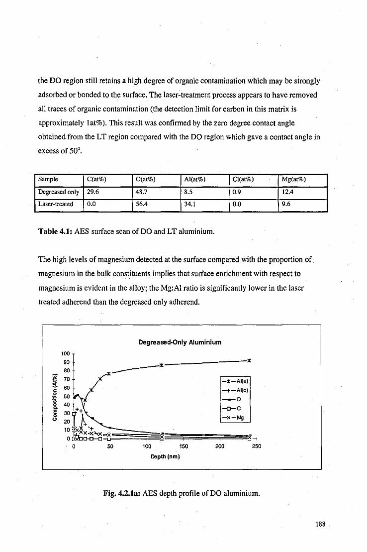
the DO region still retains a high degree of organic contamination which may be strongly
adsorbed or bonded to the surface. The laser-treatment process appears to have removed
all traces of organic contamination (the detection limit for carbon in this matrix is
approximately lat%). This result was confirmed by the zero degree contact angle
obtained from the LT region compared with the DO region which gave a contact angle in
excess of 50°.
Sample C(at%) O(at%) AI(at%) CI(at%) Mg(at%)
Degreased only 29.6 48.7 8.5 0.9 12.4
Laser-treated 0.0 56.4 34.1 0.0 9.6
Table 4.1: AES surface scan of DO and LT aluminium.
The high levels of magnesium detected at the surface compared with the proportion of
magnesium in the bulk constituents implies that surface enrichment with respect to
magnesium is evident in the alloy; the Mg:AI ratio is significantly lower in the laser
treated adherend than the degreased only adherend.
Oegreased-Only Aluminium
100
90 80 ....... x---l 70
,/ :3- 60· c: .2 50 ~ 0 40 a.
30f E 0
20 . t+,+ <.>
10 ;txx-x>,x~x ~ o ~ OO-O-O-u
-X-AI(a)
-+-AI(o)
-0
-o-C
-x-Mg
==~~~~~~.~~ 0 50 100 150 200 250
Depth (nm)
Fig. 4.2.1a: AES depth profile of DO aluminium.
188
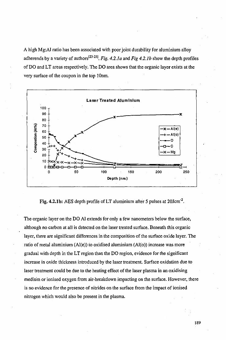
A high Mg:AI ratio has been associated with poor joint durability for aluminium alloy
adherends by a variety of authors[23-25J. Fig. 4.2.1a and Fig 4.2.1b show the depth profiles
of DO and LT areas respectively. The DO area shows that the organic layer exists at the
very surface of the coupon in the top 10nm.
100
90
80
~ 70
! 60 i 50 0. 40
20 £+ ..... + I ..... +
Laser Treated Aluminium
-:le-AI(e)
-+-AI(o)
-0
-o-C
-X-Mg ~ 30 -1-1++ '+ ,:le
10 ~ X>$X"X-x-x~---otc~~==~~~~====~==~~~~~:~~
o 50 100 150 200 250
Depth (nm)
Fig. 4.2.1b: AES depth profile of LT aluminium after 5 pulses at 20Jcm-2.
The organic layer on the DO AI extends for only a few nanometers below the surface,
although no carbon at all is detected on the laser treated surface. Beneath this organic
layer, there are significant differences in the composition ofthe surface oxide layer. The
ratio of metal aluminium (AI(e» to oxidised aluminium (AI(o» increase was more
gradual with depth in the LT region than the DO region, evidence for the significant
increase in oxide thickness introduced by the laser treatment. Surface oxidation due to
laser treatment could be due to the heating effect of the laser plasma in an oxidising
mediu'm or ionised oxygen from air-breakdown impacting on the surface. However, there
is no evidence for the presence of nitrides on the surface from the impact of ionised
nitrogen which would also be present in the plasma.
189

Photos 4.2.1c tofshow SEM micrographs of the DO and LT surfaces at low and high
magnifications. Both magnifications show little visible disparity between the surfaces and
there is clear evidence of loosely bound material, particulates and rolling lines on both
examples.
Bond Testing
Tables 4.2 and 4.3 show initial joint strengths and stressed durability results for DO and
LT, SLS aluminium joints.
Treatment Initial joint strength (N) [I Standard Deviationl
Degrease only 1895 (184)
Laser treated 4876 (845)
Grit-blast 4687 (160)
Conversion coating 4057 (313)
Table 4.2: Comparative study of initial aluminium joint strengths after various
pretreatments. Each value is the mean derived from three replicate joints.
.
Table 4.2 shows how the various surface treatments performed under initial joint strength
tests. All treatments give an increase in initial joint strength improvement in excess of
100% with respect to the DO treatment, with the laser treated coupons performing most
effectively with a 150% improvement.
Table 4.3 shows how the various surface treatments affected the stressed durability of the
aluminium joints. For an applied load of IkN, all the treated coupons show similar
improvements with mean time-to-failures (MTF) increasing by a factor of approximately
25 with respect to the DO treatments. Again, the LT coupons perform well, falling just
short of the MTF's observed with conversion coating. There is greater disparity, however,
for an applied load of l.5kN. Although all treatments show a large improvement
190

compared with the DO coupons, the LT coupons perform worst out of the two alternative
treatments.
Treatment Mean time to failure (hrs) Mean time to failure (hrs)
(lkN applied load) [I Std. Dev.] (1.5kN applied load) [I Std. Dev]
Degrease only 19 [4J <I [<I]
Laser treated 532 [35] 158 [10]
Grit-blast 465 [22] 223 [54]
Conversion coating 547 [25] 367 [24]
Table 4.3: Comparative study of stressed durability performance of aluminium joints
after various pretreatments. Each value is the mean derived from three replicate joints.
It would appear that the performance of the LT joints depends greatly on the conditions
under which they are stressed. Apart from the high-load durability performance, the LT
joints were comparable with the best of the alternative surface treatments studied.
The improvement of the adhesive properties due to LT in comparison to DO appears to be
principally due to the removal of the organic layer and extreme cleanliness of the treated
surface. The presence of a thin organic layer could prevent the formation of interatomic or
intermolecular bonds which form over a distance of a few angstroms or nanometers. No
significant change in the surface topography of the aluminium is evident from the SEM
micrographs of the LT area and AES depth profiles show only a slight thickening of the
oxide layer, hence it is unlikely that adhesi ve properties have significantly improved
through a change in surface features and structure.
191

4.2.2 Steel
Introduction
The potential of the laser for use in metal adhesion pretreatment processes prompted
further research into different adhesive systems. It was decided to conduct a comparative
study for steel coupons to see how the laser treatment process performed against some of
the most effective modern methods. In this case, the degreasing stage was omitted prior to
laser treatment as it proved to be unnecessary; in the previous study it was concluded that
the laser effectively degreased the surface during treatment.
Experimental
CRI mild steel (a cold-rolled, low-carbon steel) was cut into coupons measuring 25mm x
60mm by 211l:m thickness. The coupons were subjected to the following treatments:
(i) Degrease only: achieved by two separate IOmin ultrasonic submersions in 'Super
Purity' acetone. This process is repeated as part of the treatments (iii) and (iv) below.
(ii) Laser treatment: laser treatment was performed at an energy density of approximately
20Jcm·2 and, as the laser was rastered over the surface, each point received 40 pulses.
This was sufficient to reduce the contact angle to zero and hence produce a surface free
from organic contamination. Joints were assembled within 30 seconds of laser treatment
to minimise recontamination from the atmosphere. No degreasing was attempted prior to
laser treatment.
(iii) Degrease plus grit-blast: grit-blasting was carried out using 80/120 grade alumina
grit. The coupons were again degreased after grit-blasting.
192

(iv) Grit-blast plus silane application: grit-blasting as described in (iii) followed by
application of I % aqueous solution of Union Carbide AI87 silane· . Silane treatment has
been shown to increase bond durability through increasing interface stability[261.
Bonding tests and surface analysis were carried out using identical methods and
equipment as described in Section 4.2.1. In addition, two different surface exposure times
(SETs) were used prior to bonding the laser treated coupons to investigate the effect of
organic contamination on the bond quality. As a method of assessing bond durability, the
strength of three replicate joints for each pretreatment were also measured after 12 weeks
immersion in deionised water at 60°C.
Results and discussion
Degreased-only Mild Steel
100 _---;:c------: 90 ,,-:C
# ~~ //:C ! 60
~!~ :c~ &. 30:x,/ .
~ 20 ~ 1:1.,..._ ""-la ++.+_~ --;;:~F====+====F===: o t--+~+=+"""'F+=+ i + +
EJ:C-Fe -0
-o-C
-+-Ca
o 5 10 15 20 25 30
Depth (nrn)
Fig. 4.2.23: AES depth profile of a DO mild steel coupon.
Fig 4.2.2a shows the AES depth profile of the DO mild steel coupon. As with the
aluminium aHoy coupons, the degreasing process has left a thin, organic layer, extending
to a depth of 5-1 Onm, on the surface of the metal. There is also evidence of oxygen and
• A18? Silane is the commercial name fory-glycidoxypropylmethoxysilane.
193
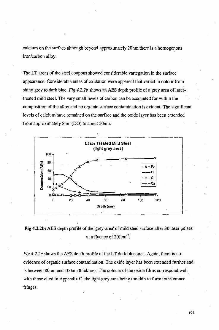
calcium on the surface although beyond approximately 20nm there is a homogenous
iron/carbon alloy.
The LT areas of the steel coupons showed considerable variegation in the surface
appearance. Considerable areas of oxidation were apparent that varied in colour from
shiny grey to dark blue. Fig 4.2.2b shows an AES depth profile of a grey area of laser
treated mild steel. The very small levels of carbon can be accounted for within the
composition of the alloy and no organic surface contamination is evident. The significant
levels of calcium have remained on the surface and the oxide layer has been extended
from approximately 8nm (DO) to about 30nm.
l-:3-c .2 '" .. &. E 8
100
Laser Treated Mild Steel (light grey area)
. x-x iK _____ :iK
80 ?/
60 /
40
20 i;><!, 6n--o-- +-+-+-o c-o-o t=+
~iK-Fe -0
-o-C
-+-ca
~~~~;;;;;::;;;;~+;;:;::;:;::;;;;F=~'F1 0 20 40 60 80 100 120
Depth (nm)
Fig 4.2.2b: AES depth profile of the 'grey-area' of mild steel surface after 30 laser pulses
at a f1uence of 20Jcm·2•
Fig 4.2.2c shows the AES depth profile of the LT dark blue area. Again, there is no
evidence of organic surface contamination. The oxide layer has been extended further and
is between 80nm and 100nm thickness. The colours of the oxide films correspond well
with those cited in Appendix C, the light grey area being too thin to form interference
fringes.
194

100
Laser Treated Mild Steel (dark blue area)
~ 80 x--x-_x----~x
! x~
~ 60 "- :t\ ..... x_x/K..... -0
-'rl+*++++++-+-+~=+=+==+ O~_
o 50 100
Depth (nm)
'j'
150
-+ 200
Fig 4.2.2c: AES depth profile of the 'blue-area' of mild steel surface after 30 laser pulses
at a fluence of 20Jcm-2.
The oxidising effect of the laser is far more pronounced on the mild steel than the
aluminium. SEM micrographs show that there is also considerable change in surface
topography due to the effects of the laser on the mild steel samples.
Photos 4.2.2d and 4.2.2e show the DO mild steel surfaces under Iow (x270) and high
(x6800) magnification respectively, both show a patchy surface with prominent cracks
visible. SEM micrographs of the laser-treated grey area on the same scale, as shown in
Photos 4.2.2/ and 4.2.2g, show a significant change in surface topography with respect to
the DO surface; there is evidence for surface melting and globules of molten metal or
oxide are apparent. There also appears to be a rippling effect caused in the LT grey area
that is best seen in Photo 4_2.2f. Such rippling effects can often be observed on laser
treated surface and are termed non-resonant periodic structures[27-291 and although the
exact mechanisms that contribute to their formation are not fully understood, they do
require surface melting followed by a rapid cooling process to 'freeze' the structures. The
dark blue, laser treated area is different stilI with a surface texture that appears much
smoother than the other two areas, as shown in Photos 4.2.2h and 4.2.2i. The extent of
195
surface melting of the dark blue area has given it a "glassy" appearance absent from
cracks and friable material.
Bond Testing
Table 4.4 shows the initial joint strengths and unstressed durability data for the CR 1 mild
steel SLS joints bonded with the aforementioned single-part epoxide after different
treatment processes.
Treatment Initial joint strength (N) Joint strength (N) after 12 weeks exposure
[I Std. Dev] [I Std. Dev]
Degrease-only 3552 [700] 3073 [732]
Laser-treated (30s SEJ) 5203 [138] 3920 [309]
Laser-treated (2760m SEJ) 4938 [307] 3979 [622]
Grit-blast . 5240 [350] 5410 [120]
Grit-blast plus silane 5160 [260] 5610 [270]
Table 4.4: Comparative study of initial joint strengths of mild steel joints after various
pretreatments and exposure conditions. Each value is the mean derived from three . replicate joints.
If the initial joint strengths are considered, the laser treated (30s SET) and the two grit
blast treated coupons all give the same level of improvement on the DO coupons within a
difference of 2%. However, after a period of 12 weeks exposure, both laser treated joints
have suffered significant weakening whilst the alternative grit-blast treatments have not
lost any of their strength. The percentage strength retention for the laser treated joints are
the worst of all the treatments, including DO, implying a low-resistance of the LT joints
to degrading mechanisms in laboratory exposure tests. This gives a strong indication that,
on mild steel, although the laser treatment ensures a good initial joint strength through
removal of surface contamination, the bond durability is compromised through the growth
196

of an oxide layer that is not passive and hence fails over the long-term on exposure to
aggressive environments.
There was no significant difference in joint strength between the SETs of 30s and 2760
mins for both initial and durability tests. A SET of 2760 mins allowed a significant build
up of organic contamination on the surface of the coupons which resulted in a radical
decrease in the wettability of the surface, see Fig 4. J.4b . This organic layer did not
appear to affect the joint quality in this case, possibly because the high-cure temperature
could have caused the contaminant to be adsorbed into the adhesive.
4.2.3 Hot-dip galvanised (HDG) mild steel
Introduction
The use'of adhesive bonding for HDG mild steel is of particular interest in the automotive
industry where the use of adhesives have been found to increase structural stiffness and
mechanical durability whilst reducing unwanted riding vibrations[301. Thus, it was
considered worthwhile to continue the laser treatment investigation on HDG mild steel
and, again, compare it with other popular adhesion pretreatments. It would also offer the
opportunity to observe how the laser treatment process interacts with a thin metal coating.
Experimental
The HDG mild steel sheet was cut into coupons measuring 55mm x 20mm by 1.2mm
thickness using a guillotine. Each coupon was subjected to one of the following surface
treatments prior to adhesive bonding. All the conversion coating treatments were
performed by Chemetall UK, Aylesbury.
(i) Degrease-only: using 'Super Purity' acetone in an ultra-sonic bath for two separate 10
minute periods.
197

(ii) TEA C02-laser treatment: at a power density of approximately 20Jcm·2. The laser was
rastered over the surface of the coupon. Three treatment levels were used such that each
point received 5, \0 or 30 laser pulses.
(iii) Phosphate-based conversion coating: Gardobond 250.
(iv) Chromate-based conversion coating: Gardobond 4504.
(v) Phosphate and Chromate based duplex conversion coating: Gardobond 250 followed
by Gardobond 4504.
Bonding
The adhesive used was XB5315, a single part, 180°C curing epoxide supplied by Ciba
Polymers. The joints were bonded in a single lap-shear configuration with 10mm overlaps.
and were held together using bulldog clips throughout the 30min duration of the cure
stage.
A Hounsfield H50KM tensometer was used to determine initial joint strengths and
Maddison-type tubes at loads of either 0.2kN or O.5kN were used to determine stressed
durability ranking. All tests were performed with three replicate joints for each set of
conditions.
Surface analysis equipment and method was identical to that described in 4.2.1.
Results and Discussion
Fig 4.2.3a shows the AES depth profile of the DO, HOG mild steel surface. There are a
significant amount of oxides evident near the surface of the coupon. The oxide levels
decrease with depth such that they fall beneath 10% after just 60nm. The carbon, in
common with the DO metals in Sections 4.2.1 and 4.2.2, is only evident in the top 20nm.
198
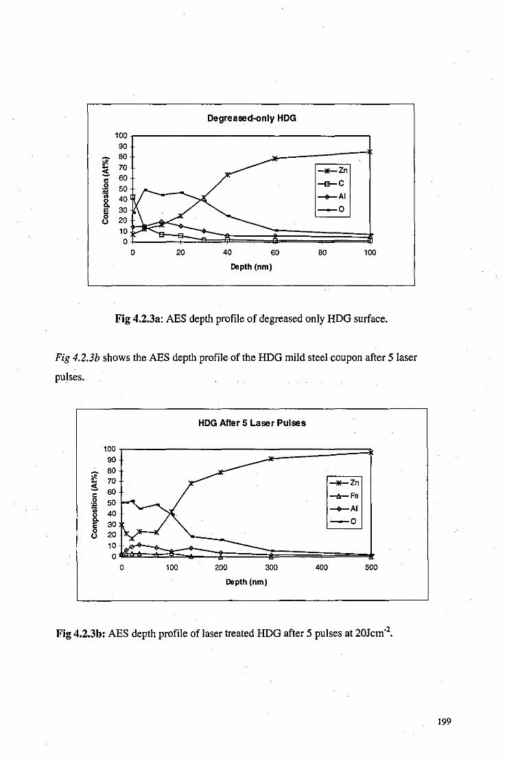
Degreased-only HOG
100 90
~ BO ~ 70 __ Zn ~ c 60 .2 50
-e-C
"" '" 40 -+-AI &. E 30 -0 0 20 (.)
10 0
0 20 40 60 BO 100
Depth (nm)
Fig 4.2.3a: AES depth profile of degreased only HDG surface.
Fig 4.2.3b shows the AES depth profile of the HDG mild steel coupon after 5 laser
pulses.
HOG After 5 Laser Pulses
100 90
*' 80
3. 70 __ Zn
c 60 __ Fe
.2 50 .t: -+-AI .. &.
30 -0 E 8
0 0 100 200 300 400 500
Depth (nm)
Fig 4.2.3b: AES depth profile of laser treated HDG after 5 pulses at 20Jcm,2.
199

There is a general increase in the depth of the oxide on the laser treated coupons
compared with the DO coupon. After 5 laser pulses, oxide levels exceed 10% for almost
300nm compared with just 60nm for the DO coupon. There is no evidence of carbon
remaining after 5 laser pulses and all organic compounds have been removed. The most
surprising result is the presence of iron at the surface of the coupon. There appears to
have been migration of the iron from underneath the zinc coating to its surface. However,
there is no evidence of iron in the bulk of the zinc coating.
Fig 4.2.3c shows the AES depth profile of HOG mild steel surface after 10 laser pulses.
The oxide layer extends to about the same depth as after 5 laser pulses. As could be
expected, there is no evidence of carbon at the surface. There is a significant increase in
iron at the surface compared with the 5 pulse coupon.
100 90
- 80 ~ 70 $ 60 c .9 50 .t:
" 40 8. E 30 0 20 <.l
10 0
0
HOG After 10 Laser Pulses
100 200 300
Depth (nm)
400
__ Zn
___ Fe
-+-AI
-0
500
Fig 4.2.3c: AES depth profile of laser treated HDG surface after 10 pulses at 20Jcm-2•
Photo 4.2.3d shows an SEM micrograph of the 5 pulse, laser treated surface at a
magnification of about x I 000. The surface has considerable micro-roughness with a lot of
loosely bound oxide globules and flakes. After 10 laser pulses, Photo 4.2.3e shows the
surface at the same scale. There is still some evidence for loosely bound oxide material,
200

but there also appears to be an adherent oxide layer fonning over the surface. Photo 4.2.3/
shows the surface at the same scale after 30 pulses. All the loosely bound material has
been removed and the oxide layer has formed a uniform coating.
Bond testing
Initial joint strength of the laser treated coupons were slightly worse than DO and
Gardobond 4504 treated coupons, although these three pretreatment methods all
performed within 10% of each other. Table 4.5 shows the narrow range of initial joint
strengths as a result of the different pretreatment processes. Increasing the number of laser
pulses from 5 to 30 had little effect on the initial joint strength.
Treatment Ioint strength (kN) [1 standard deviation)
Degrease only . 4.4 [0.81
Laser treated (5 pulses) 3.9 [0.31)
Laser treated (10 pulses) 4.0 [0.56)
Laser treated (30 pulses) 4.1 [0.22)
Gardobond 250 4.5 [0.22)
Gardobond 4504 4.5 [0.03)
Gardobond 250 + 4504 3.6 [0.11) .
Table 4.5: Comparative study of initial joint strengths of SLS, HDG joints after various
pretreatments. Each value and standard deviation is determined from three replicate
joints.
Table 4.6 shows the stressed durability performance of the various pretreatments under
applied loads of 0.2 and 0.5kN. Under an applied load of 0.2kN, the 10 pulse laser treated
coupons performed within 10% of the Gardobond 4504, the best of the alternative
pretreatments, and out-performed the DO joints. Laser treatment did not perform as well
at the higher load, faIling just short of the DO joints and far short of the
201

Gardobond 4504 treatment that out-performed all other treatments by a factor of 2 or
greater.
Treatment .Mean time-to-failure (hrs) with Mean time-to-failure (hrs) with
0.2kN applied load [I Std. Dev.] 0.5kN applied load [I Std. Dev]
Degrease only 163 [32] 85 [12]
Laser treated (5 pulses) 177 [38] 37 [11]
Laser treated (10 pulses) 217 [30] 79 [30]
Laser treated (30 pulses) 162 [30] 58 [18]
Gardobond 250 90[16] 27 [7] .
Gardobond 4504 235 [36] 172 [6] .
Gardobond 250 + 4504 198 [53] 27 [7]
Table 4.6: Comparative study of stressed durability performance of SLS, HOG joints in
DI water at 60°C after various pretreatments. Each value is the mean derived from three
replicate joints.
Surprisingly, the 10 pulse laser treatment out-performed both the 5 and 30 pulse laser
treated joints in both stressed durability tests. Stressed durability has been shown to be
dependent on the quality of the inorganic coating present on the adherend surface as
opposed to the surface cleanliness. There is a marked difference between the uniform
oxide coating formed after 30 pulses, Photo 4.2.3f, and the patchy oxide formed after 10
pulses, Photo 4.2.3e. It would appear that the increase in surface roughness, and therefore
surface area, of the 10 pulse treated surface accounts for the improvement in bond
durability. It should be noted, therefore, that increasing the number of pulses during the
laser pretreatment of metal adherends may not necessarily improve the bond quality.
4.2.4 Summary of Results
Table 4.7 compares the laser treatment process with the best of the commercial processes
and the degrease only treatment. For all the target materials, the laser treatment
202
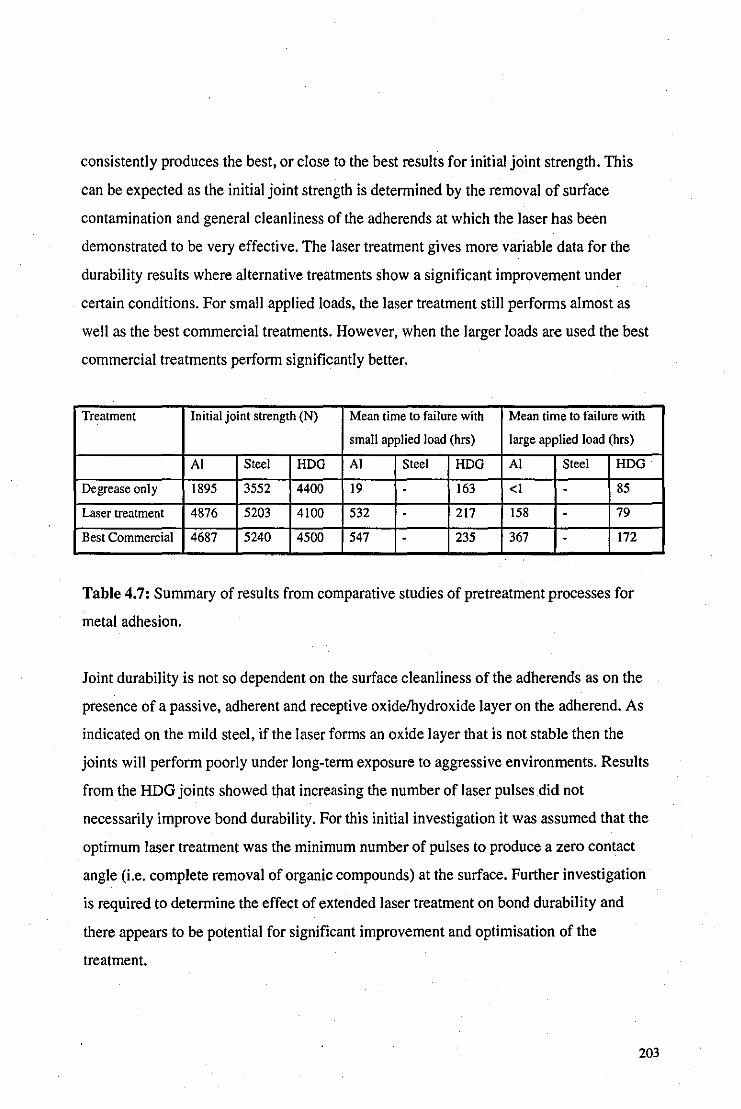
consistently produces the best, or close to the best results for initial joint strength. This
can be expected as the initial joint strength is determined by the removal of surface
contamination and general cleanliness of the adherends at which the laser has been
demonstrated to be very effective. The laser treatment gives more variable data for the
durability results where alternative treatments show a significant improvement under
certain conditions. For small applied loads, the laser treatment still performs almost as
well as the best commercial treatments. However, when the larger loads are used the best
commercial treatments perform significantly better.
Treatment Initial joint strength (N) Mean time to failure with Mean time to failure with
small applied load (hrs) large applied load (hrg)
Al Steel HDG Al Steel HDG Al Steel HDG
Degrease only 1895 3552 4400 19 . 163 <I - 85
Laser treatment 4876 5203 4\00 532 . 217 158 . 79
Best Commercial 4687 5240 4500 547 - 235 367 - 172
Table 4.7: Summary of results from comparative studies of pretreatment processes for
metal adhesion.
Joint durability is not so dependent on the surface cleanliness of the adherends as on the
presence of a passive, adherent and receptive oxide/hydroxide layer on the adherend. As
indicated on the mild steel, if the laser forms an oxide layer that is not stable then the
joints will perform poorly under long-term exposure to aggressive environments. Results
from the HDG joints showed that increasing the number of laser pulses did not
necessarily improve bond durability. For this initial investigation it was assumed that the
optimum laser treatment was the minimum number of pulses to produce a zero contact
angle (Le. complete removal of organic compounds) at the surface. Further investigation
is required to determine the effect of extended laser treatment on bond durability and
there appears to be potential for significant improvement and optimisation of the
treatment.
203
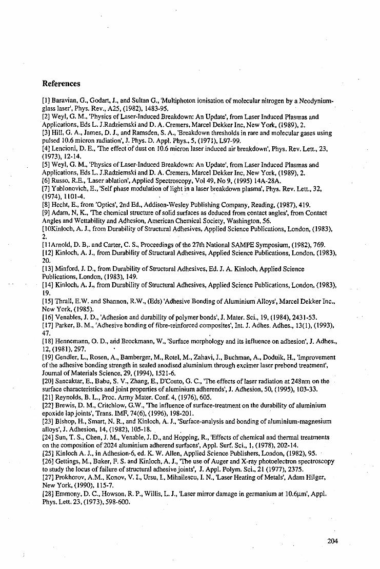
References
[I) Baravian, G., Godart, I., and Sultan G., 'Multiphoton ionisation of molecular nitrogen by a Neodyniumglass laser', Phys. Rev., A25, (1982), 1483-95. [2) Weyl, G. M., 'Physics of Laser-Induced Breakdown: An Update', from Laser Induced Plasmas and Applications, Eds L. I.Radziemski and D. A. Cremers, Marcel Dekker Inc, New York, (1989), 2. [3) Hill, G. A .. lames, D. I., and Ramsden, S. A., 'Breakdown thresholds in rare and molecular gases using pulsed 10.6 micron radiation', I. Phys. D. Appl. Phys., 5, (1971), L97-99. [4) Lencioni, D. E., 'The effect 'of dust on 10.6 micron laser induced air breakdown', Phys. Rev. Lett., 23, (1973),12-14. [5) Weyl, G. M., 'Physics of Laser-Induced Breakdown: An Update', from Laser Induced Plasmas and Applications, Eds L. I.Radziemski and D. A. Cremers, Marcel Dekker Inc, New York, (1989), 2. (6) Russo, R.E., 'Laser ablation', Applied Spectroscopy, Vol49, No 9, (1995) 14A-28A. (7) Yablonovich, E., 'Self phase modulation of light in a laser breakdown plasma', Phys. Rev. Lett., 32, (1974), 1101-4. (8) Hecht, E., from 'Optics', 2nd Ed., Addison-Wesley Publishing Company, Reading, (1987), 419. (9) Adam, N, K., 'The chemical structure of solid surfaces as deduced from contact angles', from Contact Angles and Wettability and Adhesion, American Chemical Society, Washington, 56. [IOKinloch, A. I., from Durability of Structural Adhesives, Applied Science Publications, London, (1983), 2. [I I Arnold, D. B,. and Carter, C. S., Proceedings of the 27th National SAMPE Symposium, (1982), 769. (12) Kinloch, A. I., from Durability of Structural Adhesives, Applied Science Publications, London, (1983), 20. (13) Minford, I. D., from Durability of Structural Adhesives, Ed. I. A. Kinloch, Applied Science Publications, London, (1983), 149. [14) Kinloch, A. 1., from Durability of Structural Adhesives, Applied Science Publications, London, (1983), 19. (15) Thrall, E.W. and Shannon, R.W., (Bds) 'Adhesive Bonding of Aluminium Alloys', Marcel Dekker Inc., New York, (1985). (16) Venables, I. D., 'Adhesion and durability of polymer bonds', I. Mater. Sci., 19, (1984), 2431-53. (17) Parker, B. M., 'Adhesive bonding of fibre-reinforced composites', Int. I. Adhes. Adhes., 13(1), (1993), 47. (18) Hennemann, O. D., and Brockmann, W., 'Surface morphology and its influence on adhesion', I. Adhes., 12, (1981), 297. (19) Gendler, L., Rosen, A., Bamberger, M., Rotel, M., Zahavi, I., Buchman, A., Doduik, H., 'Improvement of the adhesive bonding strength in sealed anodised aluminium through excimer laser prebond treatment', Iournal of Materials Science, 29, (1994),1521-6. (20) Sancaktar, E., Babu, S. V., Zhang, E., D'Couto, G. C., 'The effects of laser radiation at 248nm on the surface characteristics and joint properties of aluminium adherends', I. Adhesion, 50, (1995), 103-33. [21) Reynolds, B. L., Proc. Army Mater. Conf. 4, (1976), 605. (22) Brewis, D. M., Critchlow, G.W., 'The influence of surface-treatment on the durability of aluminium epoxide lap joints', Trans. IMF, 74(6), (1996),198-201. [23) Bishop, H., Smart, N. R., and Kinloch, A. I., 'Surface-analysis and bonding of aluminium-magnesium alloys', I. Adhesion, 14, (1982), 105-18. (24) Sun, T. S., Chen, I. M., Venable, I. D., and Hopping, R., 'Effects of chemical and thermal treatments on the composition of 2024 aluminium adherend surfaces', Appl. Surf. Sci., I, (1978), 202-14. (25) Kinloch A. I .. in Adhesion-6, ed. K. W. Allen, Applied Science Publishers, London, (1982), 95. (26) Gettings, M., Baker, F. S. and Kinloch, A. I., 'The use of Auger and X-ray photoelectron spectroscopy to study the locus of failure of structural adhesive joints', I. Appl. Polym. Sci., 21 (1977), 2375. (27) Prokhorov, A.M., Konov, V. I., Ursu,!., Mihailescu,!. N., 'Laser Heating of Metals', Adam Hilger, New York, (1990), 1\5-7. (28) Emmony, D. C., Howson, R. P., Willis, L. I., 'Laser mirror damage in germanium at 10.6!1m', Appl. Phys. Let!. 23, (1973), 598-600.
204

[29] Emmony, D. C., Phillips, N. l., Toyer, l. H., Willis, L. l., 'The topography of laser irradiated germanium', l. Phys. D: Appl. Phys, 8, (1975), 1472-9. [30] Coduti, P. L., Proc. 20th Anniversary Meeting of the Adhesion Soc., Hilton Head S.C., U.S.A., (23-26 Feb. 1997), 347.
205

I l' SEI EHT- 10 0 KV 110' 16 frill PHOTO' 7 5 OOpm I-----------i
UHTRfAffD A~[A
Photo 4.2.10: SEM micrograph of degrcased alwninium (magnification approx. x400). Photo 4.2.1e: SEM micrograph of degreased aluminium (magnification approx. x8000).
I L- sn EHT- 10 0 ~v liD' 14 l1li PHOTO' 1
lASER 'REAIE~ogRFA f------!
-------_._---
Photo 4.2.1d: SEM micrograph oflaser-treated aluminiwn (magnification approx. x400). Photo 4.2.1f: SEM micrograph of laseNreated aluminium (magnification approx. x8000).

Photo 4.2.2d: SEM micrograph of degreased steel (magnification approx. xI75).
Photo 4.2.2e: SEM micrograph of degreased steel (magnification approx. x7000).
Pboto 4.2.2f: SEM micrognaph of grey area of laser treated steel (magnification approx. xI75).
Photo 4.2.2g: SEM micrograph of grey area of laser treated steel (mag. approx. x7000).
Photo 4.2.2h: SEM micrognaph of blue area oflaser treated steel (magnification approx. xI75).
Photo 4.2.2i: SEM micrograph of blue area of laser treated steel (magnification approx. x7000).
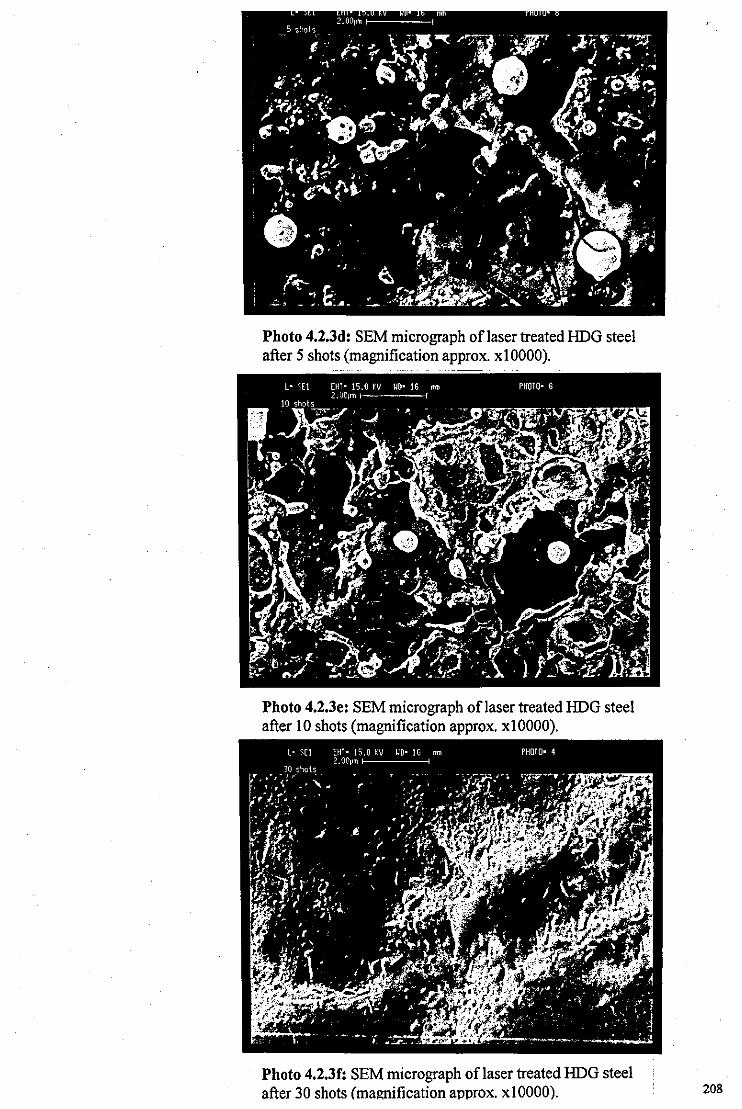
Photo 4.2.3d: SEM micrograph oflaser treated HOG steel after 5 shots (magnification approx. xIOOOO).
Photo 4.2.3e: SEM micrograph oflaser treated HOG steel after 10 shots (magnification approx. xlOOOO).
Photo 4.2.3f: SEM micrograph of laser treated HOG steel after 30 shots (magnification approx. xlOOOO). 208
Chapter 5
Conclusions and Further Work
5.1 Conclusions
This thesis has considered the use of the TEA-C02 laser in many different metal cleaning
and treatment applications. Throughout the experimental investigation an emphasis has
been placed on the accumulation of broad-ranging empirical data to give a realistic
impression of how the TEA-C02 laser will perform in different scenarios. This chapter
presents the conclusions of this work and suggestions for further work where, due to
limited time and resources, there still remains much to be done.
5.1.1 Metals without a coating.
Sub-plasma laser fluences
Metal cleaning applications that should not affect the metal substrate, such as those
suitable for sculpture cleaning, require the use of sub-plasma laser fluences to avoid
damage if the laser is the chosen method of cleaning. However, even at sub-plasma
f1uences, the TEA CO2-laser was capable of either melting or oxidising certain metals,
such as lead, or could potentially cause a temperature rise at the surface sufficient to
induce phase changes in metals such as iron and steel (see Table 2.1). With other metals
tested, however, no damage to the metal surface ensued from laser treatment and the laser
could be considered as a self-limiting cleaning tool. These metals included copper,
bronze, brass and silver which are all commonly used in sculpture and historic artefacts.
Plasmafluences
Although the production of a plasma above the surface of the metal target has been shown
to induce oxidation on aluminium[IJ, iron[2J and galvanised mild steel[3J, to various
209

degrees, this may be advantageous in certain applications. Although the formation of the
plasma prevents the majority of the laser beam from coupling directly with the metal
surface, it achieves the complete removal of organic contamination, including the
chemisorbed polar molecules that are not removed by sub-plasma laser treatment and
normal degreasing processes.
In terms of using the laser in metal adhesion pretreatments, the high levels of surface
cleanliness c~mbined with the added effect of oxidation can produce an adhesive
receptive, passive layer that assists initial bond strength and bond durability. Again,
however, we find this form of treatment is very much dependent on the target material.
Apart from performing consistently well on different adhesive systems, the laser
treatment process has the{ollowing advantages over various other forms of commercial
processes:
• Simplicity: the laser treatment is a simple, single step process that could be easily
automated, monitored and optimised.
• Economy: there are no raw materials consumed in the LT process and, once the laser
has been purchased, overheads are very low.
• Cleanliness: the LT process needs no chemical treatments at all. Other processes often
require hazardous chemicals such as environmentally damaging volatile solvents used
for initial degreasing and the unpleasant acids used in the conversion coatings.
Recently imposed restrictions on the industrial use of volatile solvents[4-71, such as the
Montreal ProtocOI[61 and the Clean Air Act[71, are making laser cleaning technologies
an attractive alternative.
• Versatility: although the three different metals used in these experiments did show
some material dependency for the effectiveness of the LT process, the LT did not
produce poor results under any of the conditions and it is likely that all metals will
respond well to laser treatment. For example, TEA C02-laser treatment has been
studied for use in dental applications where an improvement in shear strength by a
210
factor of 40 has been observed in TiIPMMA joints compared with untreated
controls[81.
• Selectivity: the directionality of the beam and simple masking methods provide the
user with control over precisely which area of the target is treated.
Other, less attractive attributes of laser treatment include the processing rate, typically
varying from between 0.25 and 1 cm2/s for the present system depending on the condition
of the substrate. For this reason, the current laser could not be considered a viable tool for
large scale pretreatment processes although the ability to focus, mask and direct the laser
may be useful for certain precision bonding requirements[91.
The laser pre-treated adherends were shown to perform consistently well in comparative
studies with popular alternatives in terms of initial joint strength and bond durability
under small loads. SEM and AES analysis showed how the surface topography and
surface chemistry altered due to the action of the laser. Visible spectroscopy provided an
in-line method of monitoring and optimising the treatment process.
5.1.2 Metals with inorganic coatings
Although it was very difficult to predict how the laser would perform on different
corroded targets, there did appear to be a clear difference in the laser's interaction with the
complex corrosion products on the surface and the simple compounds that often form in
contact with the metal.
It is usual for top-layer corrosion products to contain a high proportion of complex
molecules, such as basic sulphates, nitrates, and carbonates, whereas the interfacial
corrosion products are usually simple oxides, hydroxides, sulphides and chlorides. There
is a clear tendency for the laser to remove the more complex corrosion products whilst the
simple compounds remain. There are several reasons why this might be so:
211
• Complex molecules have far more vibrational energy states than simple molecules.
Radiation in the region of that emitted by the C02-laser is absorbed primarily by the
vibrational energy states of molecules which makes these complex molecules, in
general, far more absorptive at a given wavelength, thus increasing their susceptibility
to ablate. To illustrate this point, Figs 3.2.1 d and e show the absorption spectrum of
brochantite and cuprite for comparison.
• Surface corrosion products often contain hydrated or hydroxide groups. Water is well
known for its strong absorption of C02-laser radiation and hence molecules
containing hydrated or hydroxide groups can also be expected to exhibit strong
absorptive properties in that region.
• Many complex compounds, such as basic sulphates, chlorides and carbonates,
decompose at relatively low temperatures compared with the melting and boiling
points of simple corrosion products. Thermal decomposition of these compounds is
invariably accompanied by the expUlsion of gaseous products such as water vapour
and oxygen. Due to the rapid heating rates that can be achieved by laser ablation, the
rapid discharge of gases from the thermal decomposition process can produce an
explosive effect that could actively dislodge material.
• Simple compounds are less likely to be affected by the laser due to their typically
higher transparency and their high melting and boiling points: simple inorganic
compounds, such as NaCI, KCI and ZnSe. are commonly used for CO2-laser windows
and lenses. The proximity of the compounds to a metal heat-sink could impair the
efficiency of the heating process by thermal conduction into the substrate.
Homogenous and heterogeneous coatings
There has been a tendency in this discussion, and also in other literature, to treat different
corrosion layers as homogenous, discreet and uniform layers of single or mixtures of
chemical compounds. XRD only provides evidence of the most abundant, crystalline
chemical species and gives no indication as to how these species are distributed
throughout the corrosion layers. This thesis has shown how corroded metals of very
212

similar chemical composition can react very differently to laser treatment. For example, a
corrosion layer that may be unaffected by the laser may become susceptible to ablation if
dispersed with just a small amount of absorptive chemical species.
There is a large, although finite, number of possible corrosion products that can form on
metals, but there is an infinite number of possible mixtures and variations for the precise
composition of the corrosion layers. As a result of this fact, the effect the laser will have
on a given target can only be predicted with a limited degree of confidence and empirical
results from representative samples would be very worthwhile to ensure the required
effects are achieved on a given object.
Sculpture coatings
A possible application of the laser treatment process is in sculpture conservation. The
laser cannot be considered as a panacea for corrosion problems and is unsuitable for many
areas of work. These include
• Extreme corrosion: if the corrosion products contain information and detail of the
original surface then it is likely that these will be removed by the laser as in Case 2n,
the Roman coin. If surface corrosion is susceptible to ablation then its removal will
usually proceed until the metal substrate is reached or a necessary change in the
corrosion chemistry is encountered.
• Certain metals: lead has been shown to be oxidised or, at higher fiuences, melted, by
the laser. Fortunately, none of the other clean metals subjected to laser treatment
showed any signs of damage.
• 'Layer-by-layer' corrosion removal: during the removal of external corrosion products,
the laser invariably left a modified layer at the surface due to the thermal
decomposition of the layer. For example, the brochantite layer in Case In (the copper
roofing) could not be partially removed by the laser without leaving behind an
unsightly, brownlblack modified layer.
213
• Selective removal of complex corrosion products: the susceptibility of desirable,
uniform patina, such as brochantite, to decompose at relatively low fluences negates
the possibility to use the laser to remove unwanted corrosion products from such
underlying layers as in Case 4n, the Liverbird sculpture.
However, there are also certain areas particularly suited to the laser treatment process.
These include
• Removal of organics: many outdoor sculptures have been painted or lacquered at
some point and the remnants of these deteriorated coatings have become integrated
with the rest of the corrosion products. The laser has been shown to be successful at
the removal of all the fresh and aged organic coatings tested. The laser also has the
potential to be used for the removal of graffiti.
• Removal of complex corrosion products: the laser can remove aggressive, external
corrosion products to leave a bare metal substrate as in Case 3n(i), the body of the
blowtorch; or a passive interfacial layer as in Case 4n, the Liverbird sculpture.
• . Treatment of localised corrosion effects: the directional aspect of the laser beam
allows for the treatment of localised areas without risk of damage to the surrounding
area.
• Passivation of corrosion products: in some cases, the laser may modify the corrosion
products to increase their passive qualities as in Case 5n, the home-guard helmet.
This work presents the first detailed investigation of the use qf C02-lasers to clean and
treat various corrosion phenomena in the field of metal conservation[IO]. The process was
applied to a wide variety of corrosive systems to provide a representative sample on
which to make an evaluation. A variety of surface modification and cleaning effects have
been identified using XRD, XPS, AES, colour photography and cross-sectional
analysis[Il·12] .
214

To a large extent, this work is inconclusive. Although throughout the investigation a
detailed study was carried out on each object and a significant variety of objects were
laser treated, there still requires a large amount of work to be done before the general
capabilities of the laser in metal conservation can be assessed accurately. However, even
within this small cross-section of cases, the laser has produced some promising results. A
self-limiting cleaning regime has been demonstrated for the large majority of corrosive
systems on most of the metal substrates considered in this study. Damage to the metal
substrate was absent in all cases other than on lead targets. Undesirable exposure of the
metal substrate due to laser cleaning occurred only in a minority of cases and often a
passive, uniform interfacial layer became exposed and remained after laser treatment. The
laser was also successful at removing all tested organic coatings, both paints and lacquers.
The lasers ability at removing aged organic coatings is especially significant due to the
problems these present in modern conservation.
Although the laser produced a variety of effects on corroded and patinated surfaces, by far
the most common effect was the removal of external inorganic layers to reveal interfacial
inorganic compounds. These layers were often oxides which were protective and typically
stable, adherent, insoluble, hard and uniform. It is important to remember that the heating
effect of a C02-laser pulse on a thin corrosion layer is likely to heat the metal far more
significantly, due to absorption within the corrosion layer, than if it were incident on a
clean metal surface. Although this didn't appear to present any problems in our
investigation, it was clear that the surface temperature was elevated far in excess of those
predicted by Table 2.1.
Various in-line observations have indicated possible methods of providing feedback to
the conservator during the laser-treatment process. A flexible beam delivery system offers
control and directionality for the user and would be a necessary appendage for regular
conservation work.
215

The final assessment of the abilities of the laser as a cleaning system rests with the
requirements of the individual conservator and is largely a matter of taste and experience.
Although it is doubtful that the laser should replace any conventional conservation
techniques, it could provide a useful alternative and become another weapon in the
conservator's armoury against corrosion, and could also be used in conjunction with other
conservation tools.
5.1.3 Metals with organic coatings
All organic coatings exposed to the C02-laser were susceptible to ablation[131. We can
conclude:
• Organic coatings in general are likely to be susceptible to C02-laser ablation.
• Significant absorption takes place within organic media and allows for both paints
and lacquers to be removed.
• Artificial and natural organic media were both removed by the laser.
• The effect of ageing and weathering does not prevent organic coatings being removed
by the CO2-laser.
• A very thin layer (not visible to the naked eye) frequently exists after the C02-laser
removal of organic coatings. This layer is either carbon or hydrocarbon and is resilient
to ablation at sub-plasma fluences, but can be removed at plasma fluences. It is not
clear, at present, whether the layer is the remnants of the original coating or due to the
re-deposition of blow-off material.
• Acoustic monitoring of the ablative-piston signal can provide feedback for the
monitoring of layer-by-Iayer removal of laminated coatings.
• LIBS can provide an in-line monitoring technique for assessing the cleanliness of the
metal surface during cleaning above the plasma threshold. Plasma fluences can
remove organic residues that remain after sub-plasma cleaning.
216

5.2 Further Work
The potential exists for a great deal of research to be done in the field of the laser surface
treatment of metals, in areas of both industry and conservation.
Adhesion pretreatments
Our initial work into the use of COz-lasers in metal adhesive pretreatments has shown
very promising results although there has been little opportunity to optimise the process.
There is plenty of scope to improve the efficiency and the effectiveness of the process,
and also to expand the research to other metals not considered in this thesis. Where high
yield manufacturing processes are required, the automation of the laser treatment process
would be desirable.
Conservation
The use of lasers in the field of metal sculpture conservation has even more possibilities.
Our research concentrated on the use of C02-lasers due to the high reflectivity of metals
at that wavelength; there are no other lasers capable of emitting high-powered pulses in
that region. Current trends in laser technology have resulted in the development of pulsed
mid-infrared lasers such as Q-switched Er:YAG, pulsed Holmium:YAG, and Q-switched
CTE:YAG lasers emitting radiation at 2:9J.lm, 2.IJ.lm and 2.7J.lm respectively and with
power capabilities approaching those of the TEA-C02 laser used in our experiments .
. These lasers have found applications principally as medicallasers[l4.161 but may also have
potential to produce good results in metal cleaning applications due to the high
reflectivity of most metals in that region although, it should be noted, that these lasers are
considerably more expensive than equivalent power TEA C02-lasers. Q-Switched
Nd:YAG lasers, already popular in stone cleaning applications, emit radiation at 1.06J.lm
at which metals are significantly more absorbing. Q-switched Nd:YAG lasers have been
shown to melt copper, brass and aluminium at fluences required to remove
217

corrosion[17,18], although they have produced good results on aluminium sculpture[19]
when used with care. Using lasers that emit radiation in the region of IJlm or shorter will
result in a loss of the self-limiting nature of the cleaning process due to the decrease in
reflectivity of metals as wavelength decreases. There is, however, research being carried
out at these shorter wavelengths for the treatment of specific corrosion products, for
example, the removal of corrosion products from green patina on copper using frequency
doubled, Q-switched Nd: YAG lasers emitting radiation at 503nm[20]. Furthermore, if in
line monitoring techniques can be developed to provide accurate feedback to the
conservator. it may be possible to achieve good, controlled results for lasers of shorter
wavelengths.
Of the metals investigated in this thesis, perhaps gold is the most significant omission.
Gilding is present on a significant number of sculptures, is highly valued, but presents
many problems for the conservator. Often the gilding is damaged and becomes
sandwiched between corrosion products, making it very delicate. Gold is one of the best
reflectors of 1O.6Jlm radiation and C02-lasers would appear to have potential in removing
corrosion products from gilding.
Perhaps the largest obstacle to the acceptance of lasers in conservation is the high cost of
lasers in general. For the purchase of a laser to be economically viable it needs to be used
frequently and offer considerable improvements on existing conservation methods. If in
line monitoring techniques could be developed to a high degree of reliability then it could
be possible to use a single type of laser for all forms of cleaning and conservation.
Portability is an important factor if C02-lasers are to be a pragmatic method for
conservation of outdoor sculpture. Although the TEA COr laser used in our experiments
is bulky, heavy and required an external gas supply, equivalent lasers are now available
with far greater manoeuvrability. Laser Lines Ltd.[21] provide large, but portable TEA
C02-lasers capable of delivering 1-2J per pulse at 20Hz or greater. Sharplan Lasers[22] can
218

provide highly-portable, pulsed C02-lasers that provide 400mJ per pulse at an average
power of l50W, normally used for medical purposes.
5.3 Laser Safety
There are certain precautions that should be acknowledged during the use of high
powered lasers for ablation, especially if the laser is to be used in a public place.
Laser radiation
Body-tissue is significantly absorbing of C02-laser radiation. High-power laser radiation
can damage the surface of the skin or the cornea of the eye. A simple method of reducing
the range over which the laser beam is dangerous is by using a powerful focusing lens. A
powerful lens increases the rate of divergence of any radiation reflected from the target.
material (once laser treatment is complete, the target is likely to be highly reflective) and
hence the potential for the laser to do damage is reduced over distance. The user should
wear appropriate laser goggles during operation and should work in a suitable enclosure
in isolation from those without appropriate protection.
Noise
When the laser is used above the plasma-fluence, a considerable report is produced by the
expanding plasma after each pulse. Ear protection is advisable for the comfort of the user.
Ablation products
Different materials will produce different ablation products, some will be dangerous and
are unpleasant if the user is working in a confined area with poor ventilation. For
example, acidic sulphur compounds were detected during the treatment of the copper
roofing in Case J n; Excimer laser treatment of fluoropolymers has been shown to
219
produce HF[23.241; polymer ablation in general can produce short-chain molecules that
adhere to the lungs and oesophagus causing respiratory problems; copper alloys
frequently contain small quantities of arsenic and antimony that have been known to
concentrate near the surface[251. In general, it is advisable to use an efficient vacuum
nozzle situated close to the target irradiation area to remove blow-off material as it is
produced and to ensure that good ventilation is provided. If there is any reason to suspect
that the ablation products could be especially dangerous, then further precautions, such as
masks, should be considered. Anyone in doubt of the potential danger of ablation
products should bear in mind the story of some unfortunate doctors who employed lasers
for the removal of warts. After they experienced breathing problems it was discovered
that warts had lined the walls of their breathing canals[261.
220
References
[I] Critchlow, G. W., Brewis, D. M., Emmony, D. C., Cottam, C. A., 'Initial investigation into the effectiveness of C02-laser treatment of aluminium for adhesive bonding.' Int. J. Adhesion and Adhesives, 15(4), (1995), 233-236. [2] Critchlow, G. W., Cottam, C. A., Brewis, D. M., Emmony, D, C., 'Further investigation into the effectiveness of C02-laser treatment of metals for adhesive bonding', Int. J. Adhesion and Adhesives,
17(2), (1997),143-150. [3] Critchlow, G. W., Bedwell, K. H., and Cottam, C. A., 'The effectiveness of CO,-Iaser ablation for the treatment of HDG mild steel prior to adhesive bonding', submitted to the Transactions ofInstitute of Metal Finishing. [4] Takahara, H,. Usui, M., 'Solvent recovery technique and purification of environment in adjustment to replacing CFCs and trichloroethane', R&D: Research and Development, 43(2), April 1993, 41-3. [5] Kirschner, E. M., 'Environmental, health concerns force shift in use of organic solvents', Chemical and Engineering News, 72(25), 20" June 1994, 13-20. [6] Mc!lroy, M. S., 'Investigation of laboratory methods for cleaning typical metallic surfaces using aqueous type cleaning agents', ASTM Special Technical Publication, 1197, (1993), 373-388. [7] Triplett, T., 'ABCs of VOC control', Industrial Paint and Powder, 72(5), May 1996,4. [8] Buchman, A., Doduik, H., Rotel, M., and Zahavi, J., J. Adhes. ScL Technol. 8(10),1994,1211-1224. [9] Muller, W. D., Seliger, K., Meyerand, J., and Gilbert, J. L., J. Mater. ScL: Mater. Med., 5, (1994), 692-4. [10] Cottam, C. A., Emmony, D. C., 'Laser cleaning of metals at infra-red wavelengths', Proceedings of the Oct. 1995 LACONA I conference, Restauranterblatter, Verlag-Mayer, (1997). ~ [11] Cottam, C. A., Emmony, D. C., 'Practical assessment of the cleaning effect of C02-laser radiation
on corroded metal', submitted for publication in the refereed proceedings of the 1997, LACONA II conference. [12] Cottam, C. A., Emmony, D. E., 'Exploratory observations of the TEA-CO, laser irradiation of corroded metals', submitted for publication to Corrosion Science. [13] Cottam, C. A., Cuesta, A., 'XPS monitoring of the removal of an aged polymer coating from a metal substrate by TEA-C02 laser ablation', accepted for publication in the Journal of Material Science,
5th April 1998. [14] Merberg, G. N., 'Current status of infrared fiber optics for medical laser power delivery', Lasers in Surgery and Medicine, 13(5), (1993), 572-6. [15] Parel, J. M., Ren, Q. S., Simon, G., 'Noncontact laser photothermal keratoplasty:1. Biophysical principles and laser-beam delivery', Journal of Refractive and Corneal Surgery, 10(5), (1994), 511-8. [16] Kermani, 0., Lubatschowski, H., Ertmer, W., Krieglstein, G. K., 'Internal ablative sinostomy using a fiber delivered Q-switched CTE-YAG laser', International Opthamology, 17(4), (1993), 211-5. [17] Cottam, C. A.; unpublished work. [18] Choe, Y., from Nd:YAG Laser Cleaning of Metals, MSc project, (1996). [19] Dalton, M., from Q-Switched Nd:YAG Laser Cleaning of Gilbert's Eros Statue, MSc project, (1993). [20] Berry, A., Lynton Lasers Ltd., unpublished work. [21] Laser Lines Ltd., Beaumont Close, Banbury, Oxon, OXI6 7TQ, England. [22] Sharplan Lasers Europe Ltd., Merit House, Edgeware Road, Colindale, London NW9 5AP, England. [23] Berman, M. R., 'Excimer laser darkening of ETFE polymer films', Journal of Applied Polymer Science, 45, (1992), 111-7. [24] Wright, W. W., from Degradation in Polymer Degradation-6, Bd. N. Grassie, Elsevier, New York, 1985,1-19. [25] Hughes, R., and Rowe, M., from The Colouring, Bronzing and Patination of Metals, Thames and Hudson Ltd., London, (1991),10. [26] Friberg, T., 'Excimer laser removal of mould from paper: sterilisation and environmental considerations', presentation at the 2"d Lacona conference, April 1997.
221

Appendices
A: Electrochemical series
Metal Electrode Potential (V) Platinum +1.20 Silver +0.80 Copper +0.35 Hydrogen 0.0 Lead . -0.13 Tin -0.14 Nickel -0.25 Cadmium -0.42 Iron -0.44 Zinc -0.77 Aluminium -1.34 Magnesium -1.80 Sodium -2.72
B: Colour oftbin oxide films
Copper Oxide Nickle Oxide Iron Oxide Colour. Thickness (nm) Colour' Thickness (nm) Colour Thickness (nm) Dark brown 38 Pale brown 49 Straw 46 Red brown 42 Dark brown 54 Orange 52 Dark purple 45 Purple 57 Red brown 58 Dark violet 48 Dark violet 60 Purple 63 Dark blue 50 Dark blue 76 Violet 68 Blue green 83 Blue 72 Silvery green 88 Silvery green 112 Yellow green 97 Yellow green 120 Yellow 98 Yellow 126 Old gold III Straw 135 Orange 120 Yellow brown 162 Red 126 Dark brown 172
222
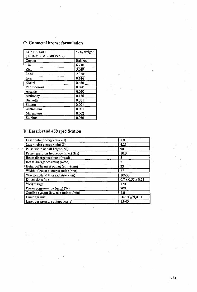
c: Gunmetal bronze formulation
LG3 BS 1400 % by weight ( GUNMETAL BRONZE) Copper· Balance Tin 6.2\0 Zinc 5.029 Lead 2.938 Iron 0.146 Nickel 0.450 Phosphorous 0.020 Arsenic 0.020 Antimony 0.136 Bismuth 0.001 Silicon 0.001 Aluminium 0.001 Manganese 0.002 Sulphur 0.030
D: Laserbrand 450 specification
Laser pulse energy (max) (J) 5.0 Laserpulse energy (min) (J) 4.25 Pulse width at half height (nS) 90 Pulse repetition frequency (max) (Hz) \0.0 Beam divergence (max) (mrad) 3 Beam divergence (min) (mrad) 2 Height of beam at output (min) (mm) 23 Width of beam at output (min) (mm) 27 Wavelength of laser radiation (nm) 10600 Dimensions (m) 0.7 x 0.57 x 0.75 Weight (kg) 120 Power consumption (mnx) (W) 900 Cooling system flow rate (min) (IImin) 2.0 Laser gas mix He/CO,lN,/CO Laser gas pressure at input (psig) 35-45
223

E: Hardness of materials
Material Micro-hardness kg/mm'
Cuo 120-135 CuS 29-30 Greenp"tina 46-115 B lackpatina 91 Copper 73 Bronze 91 Brass 121
F: Composition of Loess
Compound Quantity Compound Ouantity Compound Ouantity SiO, 59% Fe,O, trace Na,O trace AI,O, 11.5% FeO trace K,O trace CaCO, 15% . MgO trace H,O trace MgCO, 5% CaO trace P,O, trace
G: Derivation ofthe contact angle formula Tan (9/2) = 2h/d
c
A------~~~~~--~~~--------B
If the water droplet is small, it can be represented as a segment, ECD of a circle about it's centre, 0, where AB represents the sample surface. The contact angle, b, is the angle between the tangent to the circle at point D and the surface. As this tangent is at right-angles to OD, and OC is perpendicular to AB, band b' are equal. A geometric principle of circles is that the angle subtended at the centre of a circle by a given chord is twice that of the angle subtended at the circumference by the same chord, ie. b' is twice a" . Another principle states that all angles subtended at the circumference from a given chord are equal, and hence a" and a' are equal. From symmetry, a and a' are equal and hence it has been shown that b is twice a. From the diagram, tan a is equal to the height of the droplet divided by half the diameter and so, therefore, is tan b/2, where b is represented as e in the equation. This derivation is valid only if the drop is small since gravitational forces distort the shape of large drops. In this work, drop sizes were always less than 2mm in diameter and hence valid.
224
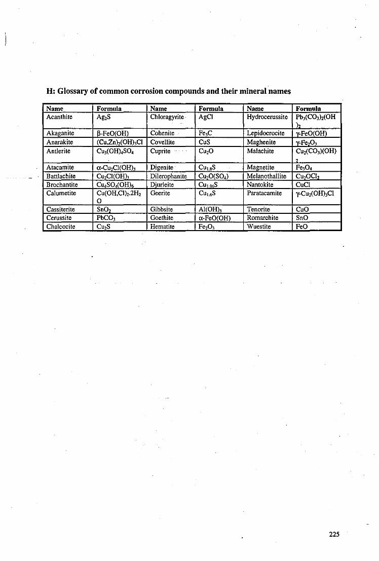
H: Glossary of common corrosion compounds and their mineral names
Name Formula Name Formula Name Formula Acanthite Ag2S Chloragyrite AgCI Hydrocerussite Pb.1(CO,h(OH
)2 Akaganite I}-FeO(OH) Cohenite .. Fe.1C Lepidocrocite y-FeO(OH)
Anarakite (Cu,Znh(OH),CI Covellite CuS Maghenite y-Fe,O, Antlerite CU.1(OH).SO. Cuprite CU20 Malachite CU2(CO,)(OH)
, Atacamite a-Cu2CI(OH), Digenite CUL'S Magnetite Fe,O. Battlachite CU2CI(OH), Dilerophanite Cu,O(SO.) Melanothallite CU2OCI2 Brochantite Cll4S0.(OH)6 Djurleite CU ,96S Nantokite CuCI Calumetite Cu(OH,CI),.2H2 Geerite CUL6S Paratacamite 'Y-Cu,(OHhCl
0 Cassiterite SnO, Gibbsite AI(OH), Tenorite CuO Cerussite PbCO.1 Goethite cx-FeO(OH) Romarchite SnO Chalcocite Cll,S Hem.tite Fe,O, Wuestite FeO
225