team 1 - final report
TRANSCRIPT
i
RESTAURANT MANAGEMENT SYSTEM
Submitted to Dr. Lee Iverson
On July 25, 2006
By
Team 1
Corry Yang Clement Wu
Tina Lin Alan Chang
EECE 474 The University of British Columbia

ii
RESTAURANT MANAGEMENT SYSTEM
Submitted to Professor Lee Iverson
By
Team 1
Corry Yang Clement Wu
Tina Lin Alan Chang
EECE 474 The University of British Columbia
July 25, 2006

ii
ABSTRACT
Customer satisfaction is the key to success for any business. In a restaurant, the
traditional hand-waving method for calling services is inefficient often leading to many
complaints. The Restaurant Management System increases operational efficiency through
use of an internal wireless communications system and a statistical data processing unit.
The communications system increases customer satisfaction by leaving a transmitter at
each table which the customer can use to request for a server. A data processing unit
allows managers and owners to easily monitor restaurant functions and employee
progress. To make this system a reality, Atmel’s ATmega16 microcontroller,
Maxstream’s XBee/XBee-PRO Zigbee transceivers and the TM162ADA7-2LCD Liquid
Crystal Display (LCD) will be the key parts that will be used.
iii
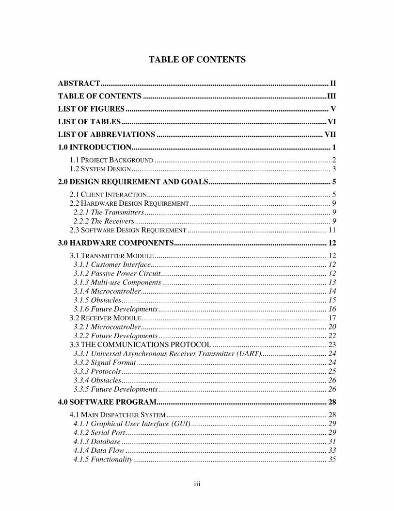
TABLE OF CONTENTS
ABSTRACT...................................................................................................................... II
TABLE OF CONTENTS ...............................................................................................III
LIST OF FIGURES ......................................................................................................... V
LIST OF TABLES ..........................................................................................................VI
LIST OF ABBREVIATIONS ...................................................................................... VII
1.0 INTRODUCTION....................................................................................................... 1
1.1 PROJECT BACKGROUND ........................................................................................... 2 1.2 SYSTEM DESIGN....................................................................................................... 3
2.0 DESIGN REQUIREMENT AND GOALS............................................................... 5
2.1 CLIENT INTERACTION............................................................................................... 5 2.2 HARDWARE DESIGN REQUIREMENT......................................................................... 9
2.2.1 The Transmitters ................................................................................................ 9 2.2.2 The Receivers ..................................................................................................... 9
2.3 SOFTWARE DESIGN REQUIREMENT ........................................................................ 11
3.0 HARDWARE COMPONENTS............................................................................... 12
3.1 TRANSMITTER MODULE ......................................................................................... 12 3.1.1 Customer Interface........................................................................................... 12 3.1.2 Passive Power Circuit...................................................................................... 12 3.1.3 Multi-use Components ..................................................................................... 13 3.1.4 Microcontroller................................................................................................ 14 3.1.5 Obstacles.......................................................................................................... 15 3.1.6 Future Developments ....................................................................................... 16
3.2 RECEIVER MODULE................................................................................................ 17 3.2.1 Microcontroller................................................................................................ 20 3.2.2 Future Developments ....................................................................................... 22
3.3 THE COMMUNICATIONS PROTOCOL ........................................................... 23 3.3.1 Universal Asynchronous Receiver Transmitter (UART).................................. 24 3.3.2 Signal Format .................................................................................................. 24 3.3.3 Protocols .......................................................................................................... 25 3.3.4 Obstacles.......................................................................................................... 26 3.3.5 Future Developments ....................................................................................... 26
4.0 SOFTWARE PROGRAM........................................................................................ 28
4.1 MAIN DISPATCHER SYSTEM ................................................................................... 28 4.1.1 Graphical User Interface (GUI) ...................................................................... 29 4.1.2 Serial Port........................................................................................................ 29 4.1.3 Database .......................................................................................................... 31 4.1.4 Data Flow ........................................................................................................ 33 4.1.5 Functionality .................................................................................................... 35
iv
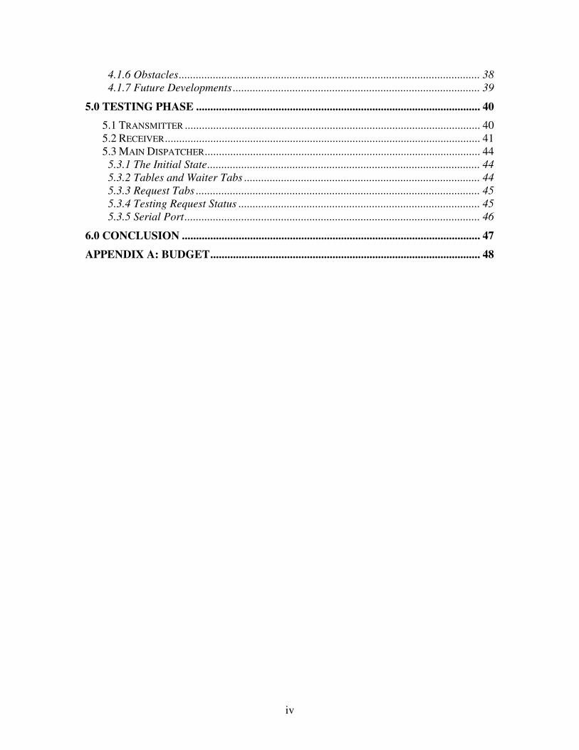
4.1.6 Obstacles.......................................................................................................... 38 4.1.7 Future Developments ....................................................................................... 39
5.0 TESTING PHASE .................................................................................................... 40
5.1 TRANSMITTER ........................................................................................................ 40 5.2 RECEIVER............................................................................................................... 41 5.3 MAIN DISPATCHER................................................................................................. 44
5.3.1 The Initial State................................................................................................ 44 5.3.2 Tables and Waiter Tabs ................................................................................... 44 5.3.3 Request Tabs .................................................................................................... 45 5.3.4 Testing Request Status ..................................................................................... 45 5.3.5 Serial Port........................................................................................................ 46
6.0 CONCLUSION ......................................................................................................... 47
APPENDIX A: BUDGET............................................................................................... 48
v
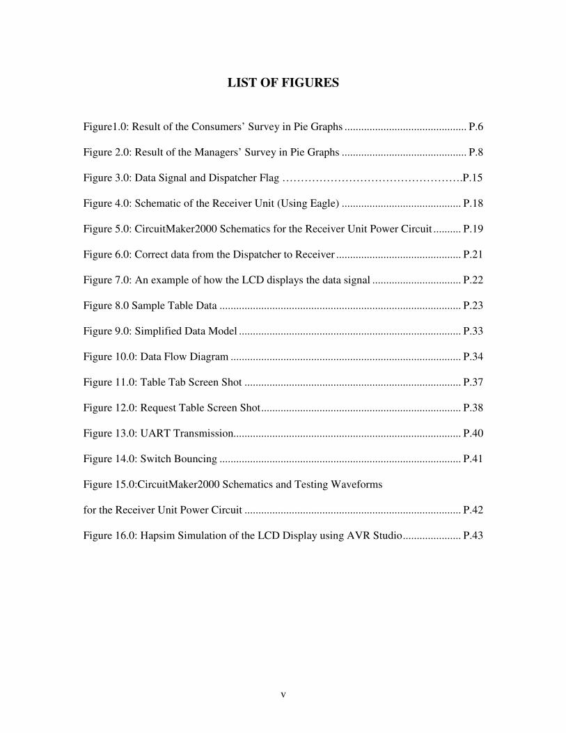
LIST OF FIGURES
Figure1.0: Result of the Consumers’ Survey in Pie Graphs ............................................ P.6
Figure 2.0: Result of the Managers’ Survey in Pie Graphs ............................................. P.8
Figure 3.0: Data Signal and Dispatcher Flag ………………………………………….P.15
Figure 4.0: Schematic of the Receiver Unit (Using Eagle) ........................................... P.18
Figure 5.0: CircuitMaker2000 Schematics for the Receiver Unit Power Circuit .......... P.19
Figure 6.0: Correct data from the Dispatcher to Receiver ............................................. P.21
Figure 7.0: An example of how the LCD displays the data signal ................................ P.22
Figure 8.0 Sample Table Data ....................................................................................... P.23
Figure 9.0: Simplified Data Model ................................................................................ P.33
Figure 10.0: Data Flow Diagram ................................................................................... P.34
Figure 11.0: Table Tab Screen Shot .............................................................................. P.37
Figure 12.0: Request Table Screen Shot........................................................................ P.38
Figure 13.0: UART Transmission.................................................................................. P.40
Figure 14.0: Switch Bouncing ....................................................................................... P.41
Figure 15.0:CircuitMaker2000 Schematics and Testing Waveforms
for the Receiver Unit Power Circuit .............................................................................. P.42
Figure 16.0: Hapsim Simulation of the LCD Display using AVR Studio..................... P.43
vi
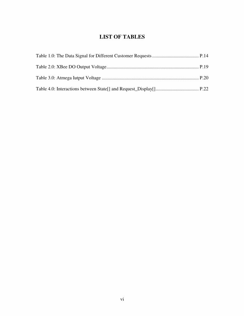
LIST OF TABLES
Table 1.0: The Data Signal for Different Customer Requests ....................................... P.14
Table 2.0: XBee DO Output Voltage............................................................................. P.19
Table 3.0: Atmega Iutput Voltage ................................................................................. P.20
Table 4.0: Interactions between State[] and Request_Display[].................................... P.22
vii
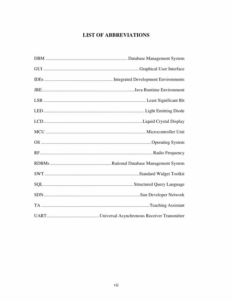
LIST OF ABBREVIATIONS
DBM ........................................................................ Database Management System
GUI ....................................................................................Graphical User Interface
IDEs ............................................................ Integrated Development Environments
JRE.................................................................................Java Runtime Environment
LSB .......................................................................................... Least Significant Bit
LED......................................................................................... Light Emitting Diode
LCD.......................................................................................Liquid Crystal Display
MCU ........................................................................................ Microcontroller Unit
OS .................................................................................................Operating System
RF................................................................................................... Radio Frequency
RDBMs ......................................................Rational Database Management System
SWT ...................................................................................Standard Widget Toolkit
SQL............................................................................... Structured Query Language
SDN.....................................................................................Sun Developer Network
TA ...............................................................................................Teaching Assistant
UART..............................................Universal Asynchronous Receiver Transmitter

1
1.0 INTRODUCTION
In many popular restaurants, waiters/waitresses tend to miss out on tables or customers’
calls during busy hours potentially decreasing ones clientele. While this is an ongoing
issue, there is still no product that drastically improves the communication between the
servers and the customers in the current market. Hence, the goal is to design a system in
which the customers can call their servers easily and help the restaurant increase overall
efficiency.
The Restaurant Management System incorporates Radio Frequency (RF) communication
hardware alongside a statistical data processing unit. An internal wireless
communication system will allow prompt notification to the server when a customer
requires service. Moreover, servers can also be more focused on serving their current
customers and save their time and energy from always keeping an eye out for needy
customers.
The data processing unit will have a database for incoming signals, a program to
manipulate data and a Graphical User Interface (GUI). On top of meeting the needs of
customers, restaurant managers can also monitor the response time of their
waiters/waitresses through use of this system. Hardworking, proficient employees will
become more recognized while lazy, inefficient employees become motivated to improve.
As a result, the restaurant becomes more efficient and possibly increasing morale while
improving the level of customer satisfaction.
2
There are three main components to the system: Transmitters, Receivers and the Main
Dispatcher. This report will discuss the updated system design and specifications of each
component. Further explanations will be provided reviewing the parts selection process
of our main components and testing processes.
1.1 PROJECT BACKGROUND
One system that is currently in the market is the Coaster Lite™ by Long Range
Systems. [http://pager.net/Long-Range-Systems/push-for-service-coaster-lite.html] The Coaster
Lite consists of only one button. When the customers require assistance, they will
press the button and the Coaster Lite will glow in the dark. The Servers will go to
tables that have a glowing Coaster Lite. Nonetheless, this system remains inefficient
because it requires servers’ constant visual attentions to the device.
The RF technology used in the project of Summer 2005 Team 1, “Computer Interface
Tracking System”, inspires our group in our RF design.
[http://www.ece.ubc.ca/~elec474/reports/summer05/Team%201%20Final%20Report.pdf]. It is a
system which “involves 4 receiver modules and several transmitter modules” and
“[t]he receiver-modules detect the received signal strength and output it to the central
board”. Although the numbers of RF components and the principle of operations are
different, our group still find their RF communication design useful in building our
own system. For example, they have a central system which receives and processes
the signals from the transmitters, a GUI which can “continuously listen for signals
coming in from the microcontroller ATmega32”, and a functional RF communication
3
scheme. Moreover, their project has provided us a lot of ideas regarding signal
transmission and identification.
Another project that can contribute to our design is Team 7’s “Radio Frequency Foot
Pressure Measuring System” in also of the same semester. Our group finds that the
ZigBee-PRO transceivers implementation and their detailed explanation in how data
are transmitted using RF can be an important source of information for our RF
communication design too.
In addition, Teaching Assistant (TA) Farshid mentioned about a hospital room
occupancy project that was done last term in 2005-2006. We can definitely draw
references to their dispatching system and microcontroller designs. Unfortunately, the
report is not posted online yet. Hence, we are making a request to professor Iverson to
see the final project report and are still waiting for his response.
Lastly, we also have conducted several interviews with waiters/waitresses who are
currently working in various restaurants. According to their responses, we were able
to sketch out the common requests and implement them in our designs.
1.2 SYSTEM DESIGN
Restaurant Application System is specifically made to increase efficiency of the
restaurant with three distinct components: Transmitters, Receivers, and a Main
Dispatcher software program. Whenever a customer requires help, their request can

4
be more promptly answered through use of the Transmitter which will be located on
each table. The Transmitter will then send a wireless signal to the Main Dispatcher to
be forwarded to the Receiver of your server.
The customer may send either a general request or a bill request by activating the
appropriate switch on the Transmitter. When a general request is sent, your server
will receive a notification on the LCD of their Receiver and will come to your table at
the earliest convenience. To help decrease wait time, the bill request first signals the
cashier to print out the bill. Once the bill is printed, your server will then be notified
to pick up the bill and bring it to your table. Because of this functionality, the main
dispatcher software is suggested to be installed at cashier so that bills may be printed
once a bill request is received.
With the Main Dispatcher software, the store manager may manage waiter and table
assignments through this software program. Further statistics such as incoming
request time and request completion times will also be logged and saved for
administrative purposes. Management users can use this data during promotion and
awards processes. Restaurants will be able to significantly increase overall efficiency
of operations and customer satisfaction through use of the System.
5
2.0 DESIGN REQUIREMENT AND GOALS
2.1 CLIENT INTERACTION
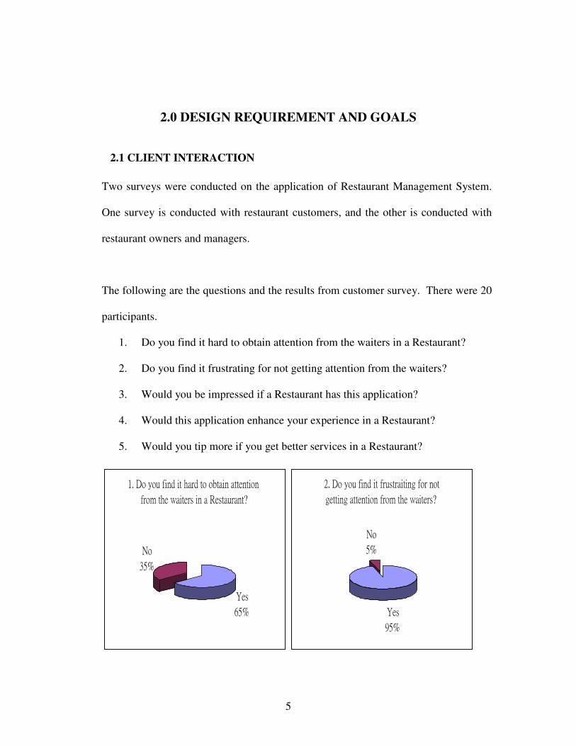
Two surveys were conducted on the application of Restaurant Management System.
One survey is conducted with restaurant customers, and the other is conducted with
restaurant owners and managers.
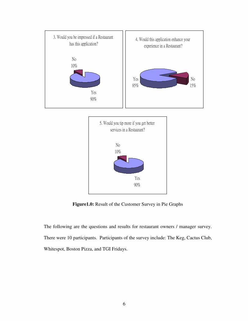
The following are the questions and the results from customer survey. There were 20
participants.
1. Do you find it hard to obtain attention from the waiters in a Restaurant?
2. Do you find it frustrating for not getting attention from the waiters?
3. Would you be impressed if a Restaurant has this application?
4. Would this application enhance your experience in a Restaurant?
5. Would you tip more if you get better services in a Restaurant?
6
Figure1.0: Result of the Customer Survey in Pie Graphs
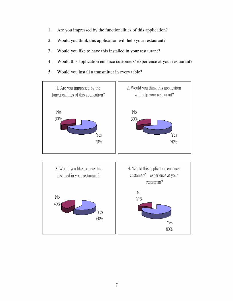
The following are the questions and results for restaurant owners / manager survey.
There were 10 participants. Participants of the survey include: The Keg, Cactus Club,
Whitespot, Boston Pizza, and TGI Fridays.
7
1. Are you impressed by the functionalities of this application?
2. Would you think this application will help your restaurant?
3. Would you like to have this installed in your restaurant?
4. Would this application enhance customers’ experience at your restaurant?
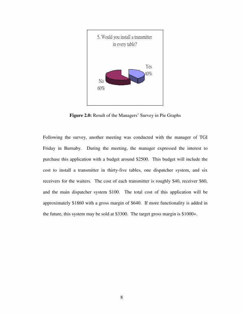
5. Would you install a transmitter in every table?
8
Figure 2.0: Result of the Managers’ Survey in Pie Graphs
Following the survey, another meeting was conducted with the manager of TGI
Friday in Burnaby. During the meeting, the manager expressed the interest to
purchase this application with a budget around $2500. This budget will include the
cost to install a transmitter in thirty-five tables, one dispatcher system, and six
receivers for the waiters. The cost of each transmitter is roughly $40, receiver $60,
and the main dispatcher system $100. The total cost of this application will be
approximately $1860 with a gross margin of $640. If more functionality is added in
the future, this system may be sold at $3300. The target gross margin is $1000+.

9
2.2 HARDWARE DESIGN REQUIREMENT
2.2.1 The Transmitters
The Transmitter is the first stage of the Restaurant Management System that
allows customer interaction. With a flick of a switch, a server will be notified
and will come to the customer ending the days where they would need to search
for a server or wave to get the attention of one. There are three main
requirements that are adhered to when designing the Transmitter.
a. Ease of Use – The device must be as customer-friendly as possible. The
design should be simple and straightforward to the extent that usage would be
self-explanatory.
b. Low Power Consumption – Ideally, the transmitters should be able to run
for a month without needing to change the battery.
c. Low Cost – Since the transmitter is the most widespread device in the
system, unit cost must be kept to a minimum.
2.2.2 The Receivers
Waiter or waitress given this device will wear the Receiver unit during his or
her shifts within the restaurant. In peak hours, he or she should be able to read
off from the LCD display regarding pending customers in one’s assigned zone.
Hence, a few key hardware requirements can be concluded.

10
1. The device should be mobile and portable enough for the restaurants
servers to carry. In addition, it should also have a reasonable size, so
that the waiter/waitress can keep it in his or her vision, such as the
wrist area (like a watch) or around the waist (clipped on the belt).
2. Power consumption should be low enough, so the Receiver unit can
use the same +9V battery for at least 2 weeks.
3. LCD should use a reasonable font size, so the waiter/waitress feels
comfortable skimming through it during busy hours
4. Proper alarming method is also a nice feature to have, mechanism
such as vibrations or flashings are good ways to notify the servers.
5. Communication between Dispatcher should be successful in most
cases.
6. Able to have special visual cue for tables who have been waited for
too long or for VIP guest tables.
In addition, to demonstrate the Dispatcher and Transmitter can send requests in
a different zone, i.e. Zone2. The Receiver should also display Zone2 View using
the same Receiver unit. However, this is only implemented for the
demonstration.
11
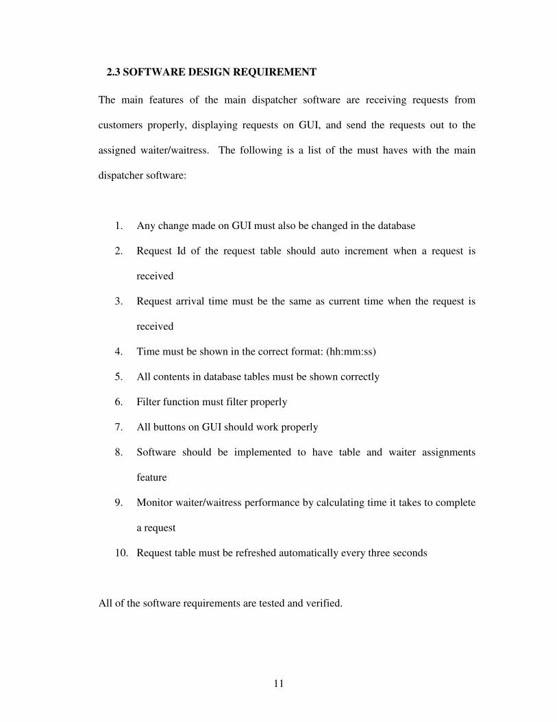
2.3 SOFTWARE DESIGN REQUIREMENT
The main features of the main dispatcher software are receiving requests from
customers properly, displaying requests on GUI, and send the requests out to the
assigned waiter/waitress. The following is a list of the must haves with the main
dispatcher software:
1. Any change made on GUI must also be changed in the database
2. Request Id of the request table should auto increment when a request is
received
3. Request arrival time must be the same as current time when the request is
received
4. Time must be shown in the correct format: (hh:mm:ss)
5. All contents in database tables must be shown correctly
6. Filter function must filter properly
7. All buttons on GUI should work properly
8. Software should be implemented to have table and waiter assignments
feature
9. Monitor waiter/waitress performance by calculating time it takes to complete
a request
10. Request table must be refreshed automatically every three seconds
All of the software requirements are tested and verified.

12
3.0 HARDWARE COMPONENTS
3.1 TRANSMITTER MODULE
The final design of the Transmitter consists of two Rocker Switches used to signal a
waiter whenever you would like your bill or have a general request. When a switch is
turned ON, an LED lights up to indicate that the request is active. Internally, the
Transmitter is powered by a 9V battery coupled with a passive power circuit to
conserve power. Other than the microcontroller and transmitter, low-cost
components such as resistors and BJT transistors are used to minimize cost.
3.1.1 Customer Interface
The initial customer interface of the Transmitter consisted of only one rocker
switch and one LED. Whenever the switch is activated, the LED would turn on
and a server would be requested. After further thought and consultation with
local restaurants, a second set was added to facilitate a Bill request. At the end
of every meal, a bill is always requested so it is only logical to implement the
function. Lastly, the traditional ON/OFF switch was removed to prevent
accidentally turning off the device.
3.1.2 Passive Power Circuit
For the majority of time, both rocker switches are in the OFF position and the
Transmitter is just idling away, wasting unnecessary power. Based on this
observation, the rocker switches are given a second duty of controlling the
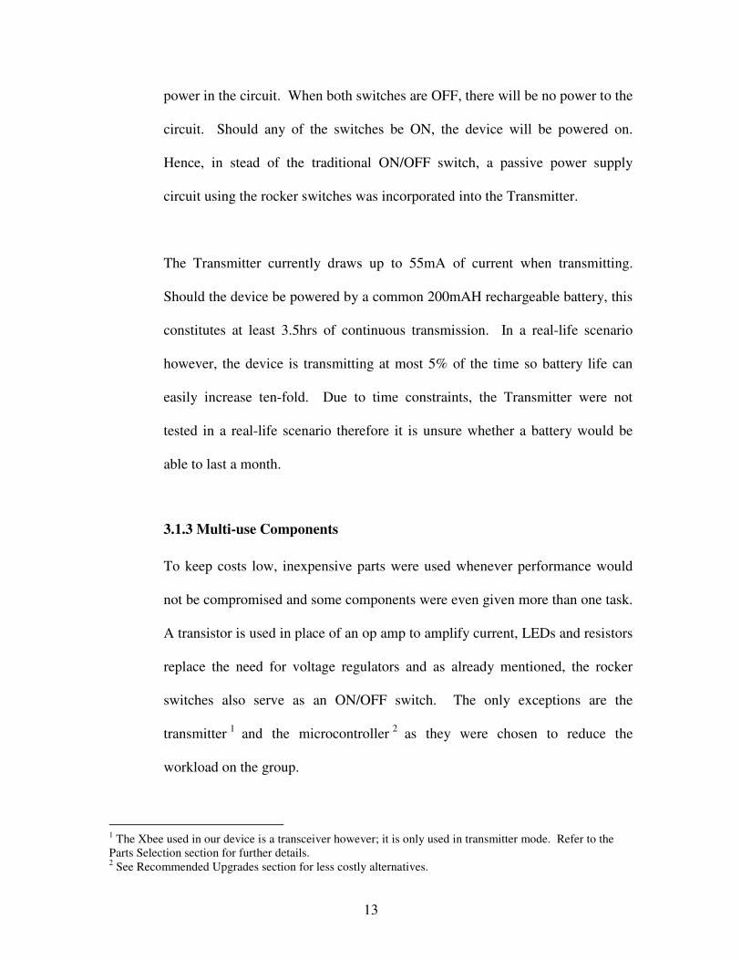
13
power in the circuit. When both switches are OFF, there will be no power to the
circuit. Should any of the switches be ON, the device will be powered on.
Hence, in stead of the traditional ON/OFF switch, a passive power supply
circuit using the rocker switches was incorporated into the Transmitter.
The Transmitter currently draws up to 55mA of current when transmitting.
Should the device be powered by a common 200mAH rechargeable battery, this
constitutes at least 3.5hrs of continuous transmission. In a real-life scenario
however, the device is transmitting at most 5% of the time so battery life can
easily increase ten-fold. Due to time constraints, the Transmitter were not
tested in a real-life scenario therefore it is unsure whether a battery would be
able to last a month.
3.1.3 Multi-use Components
To keep costs low, inexpensive parts were used whenever performance would
not be compromised and some components were even given more than one task.
A transistor is used in place of an op amp to amplify current, LEDs and resistors
replace the need for voltage regulators and as already mentioned, the rocker
switches also serve as an ON/OFF switch. The only exceptions are the
transmitter 1 and the microcontroller 2 as they were chosen to reduce the
workload on the group.
1 The Xbee used in our device is a transceiver however; it is only used in transmitter mode. Refer to the Parts Selection section for further details. 2 See Recommended Upgrades section for less costly alternatives.
14
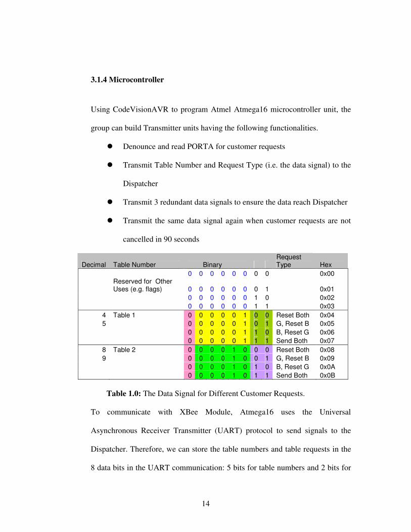
3.1.4 Microcontroller
Using CodeVisionAVR to program Atmel Atmega16 microcontroller unit, the
group can build Transmitter units having the following functionalities.
� Denounce and read PORTA for customer requests
� Transmit Table Number and Request Type (i.e. the data signal) to the
Dispatcher
� Transmit 3 redundant data signals to ensure the data reach Dispatcher
� Transmit the same data signal again when customer requests are not
cancelled in 90 seconds
Decimal Table Number Binary Request Type Hex
0 0 0 0 0 0 0 0 0x00
Reserved for Other Uses (e.g. flags) 0 0 0 0 0 0 0 1 0x01
0 0 0 0 0 0 1 0 0x02 0 0 0 0 0 0 1 1 0x03
4 Table 1 0 0 0 0 0 1 0 0 Reset Both 0x04 5 0 0 0 0 0 1 0 1 G, Reset B 0x05
0 0 0 0 0 1 1 0 B, Reset G 0x06 0 0 0 0 0 1 1 1 Send Both 0x07
8 Table 2 0 0 0 0 1 0 0 0 Reset Both 0x08 9 0 0 0 0 1 0 0 1 G, Reset B 0x09
0 0 0 0 1 0 1 0 B, Reset G 0x0A 0 0 0 0 1 0 1 1 Send Both 0x0B
Table 1.0: The Data Signal for Different Customer Requests.
To communicate with XBee Module, Atmega16 uses the Universal
Asynchronous Receiver Transmitter (UART) protocol to send signals to the
Dispatcher. Therefore, we can store the table numbers and table requests in the
8 data bits in the UART communication: 5 bits for table numbers and 2 bits for

15
requests types. Bit 7 is reserved as Dispatcher Flag to distinguish between the
Transmitter data signals and the Dispatcher data signals. A restaurant can have a
maximum number of 2^5=32 tables using this algorithm..
Transmitter Data Signal:
Dispatcher Data Signal:
Figure 3.0: Data Signals and Dispatcher Flag
Within the time range between 1 and 10 seconds, 3 Redundant signals are sent
in randomized time periods using the rand() function predefined in C.
Consequently, the method reduces the risks of collisions because not the
possibility the signals being transmitted and received in the same time is small.
In addition, the redundant signal which will be processed by the Dispatcher also
provides assurance to the accuracy of the signals.
If in any case, the data signals are not processed by the Dispatcher; for example,
the data signals are lost or the waiters are to busy helping other customers. The
transmitter will resend the original signal in 90 seconds using a simple counter
loop.
3.1.5 Obstacles
Power Requirements:
In the initial design of the transmitter circuitry, only Vcc was considered and the
components were naively powered using a simple resistor voltage divider
0 0 0 0 0 1 X X 1 0 0 0 0 1 X X

16
controlled by a two-transistor OR gate. After further examination of the
ATMega16 and XBee datasheets were current requirements finally noted. Due
to significantly different requirements of the two devices (ATMega16’s 5V @
12ma vs XBee’s 3.3V @ 45ma), this issue proved to be a big obstacle.
The initial approach was to use an op-amp as a current amplifier but this idea
would actually make the circuit even more complicated by adding many more
components and requiring an additional set of voltages to power it. After
extensive research on our requirements, a new Passive Power Circuit was
implemented consisting of a two-diode OR gate to power the ATMega16 which
in turn activates a transistor current amplifier that will power the XBee.
3.1.6 Future Developments
If we continue to use the XBee module beyond our prototypes, we can also
connect the DO pin from the XBee to Atmega16. By receiving an ACK,
acknowledgement packet, the Transmitter will be able to know exactly when the
transmissions fail (pg.20 of the XBee product manual). In this way, the
Transmitter unit will not need to send out redundant data signals as often and
the data signals will be less likely to collide in RF channel.

17
Although the cost of XBee is a little bit high for the cost per table, decent
wireless communication cannot be achieved with devices that transmit only.
Mutual communication is essential between the Dispatcher and Transmitters to
find the best time frame to send data signals in a clear channel.
3.2 RECEIVER MODULE
The hardware aspect of the Receiver Unit includes 5 different components: the power
switch, the multiplexer switch, the Atmega16 MCU, the XBee unit and the TM162A
LCD module.
� Power Switch: Turn the Receiver ON/OFF
� Multiplexer Switch: If it is on, then it will send a signal to PORTB to show
Zone2 view on the LCD
� Atmega16: It receives, stores and manipulate incoming data signals from the
XBee
� XBee: It receives the data from Dispatcher then uses UART to give data to
Atmega16
� LCD: It prints out table numbers and pending requests
18
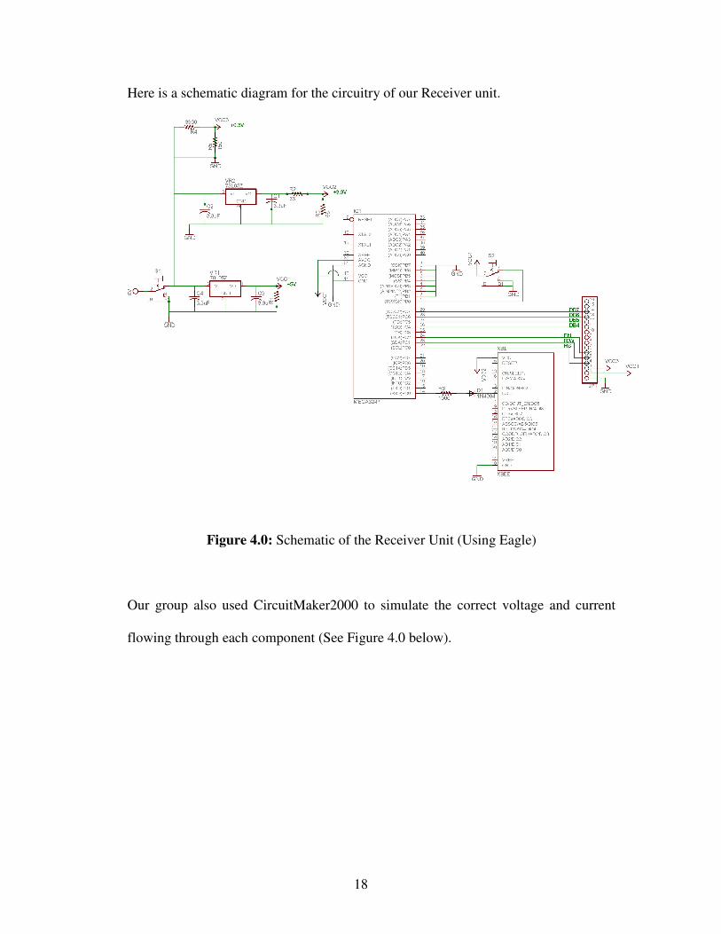
Here is a schematic diagram for the circuitry of our Receiver unit.
Figure 4.0: Schematic of the Receiver Unit (Using Eagle)
Our group also used CircuitMaker2000 to simulate the correct voltage and current
flowing through each component (See Figure 4.0 below).
19
+V
V25V
+V
V12.8V
D1DIODE
R61k
S1C2
3.3uF
C43.3uF
C33.3uF
C13.3uF
IN
COM
OUT
U278L05
IN
COM
OUT
U178L05
+
-
Vs19V
R5150
R43.9k
R368
R133
R2400
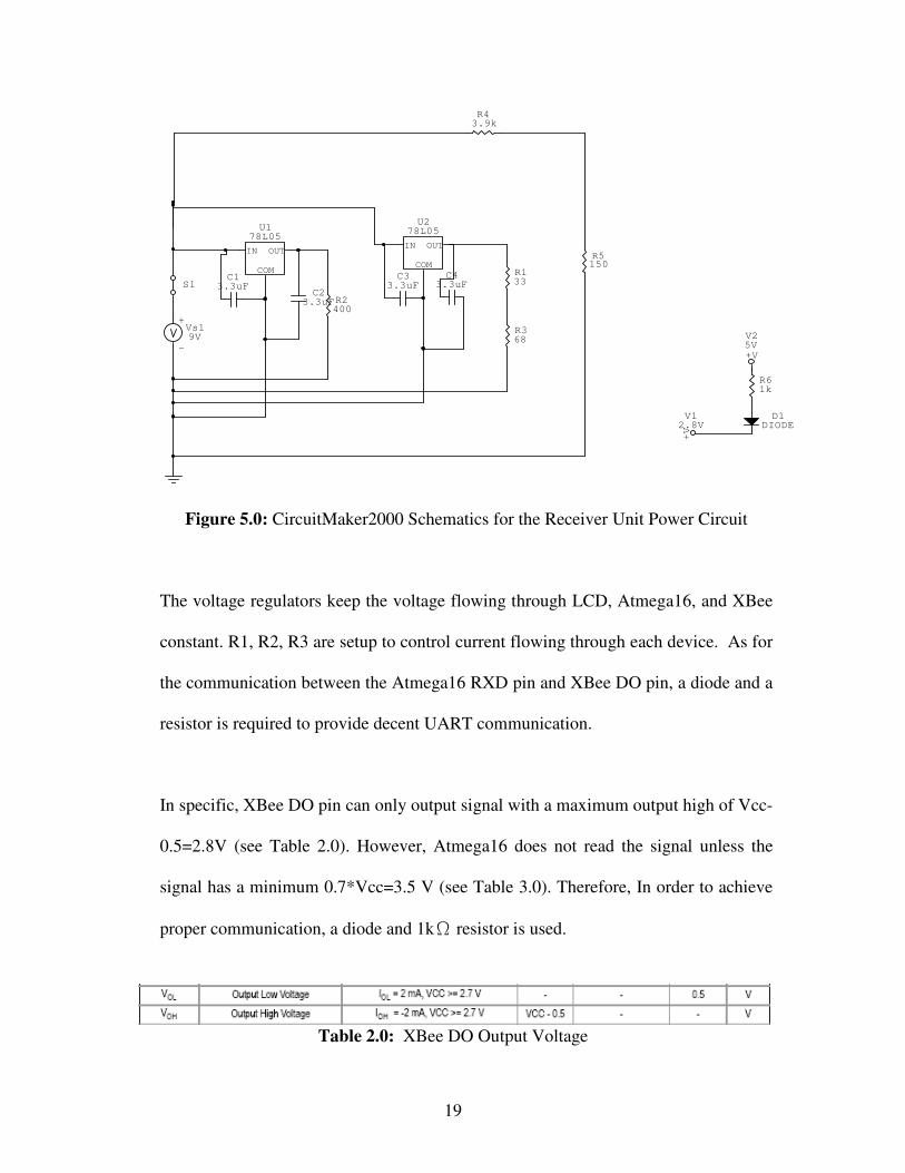
Figure 5.0: CircuitMaker2000 Schematics for the Receiver Unit Power Circuit
The voltage regulators keep the voltage flowing through LCD, Atmega16, and XBee
constant. R1, R2, R3 are setup to control current flowing through each device. As for
the communication between the Atmega16 RXD pin and XBee DO pin, a diode and a
resistor is required to provide decent UART communication.
In specific, XBee DO pin can only output signal with a maximum output high of Vcc-
0.5=2.8V (see Table 2.0). However, Atmega16 does not read the signal unless the
signal has a minimum 0.7*Vcc=3.5 V (see Table 3.0). Therefore, In order to achieve
proper communication, a diode and 1k resistor is used.
Table 2.0: XBee DO Output Voltage
20
Table 3.0: Atmega Iutput Voltage
3.2.1 Microcontroller
Using CodeVisionAVR to program our Atmel Atmega16 microcontroller unit,
our team can build Receiver units which have the following functionalities.
� Debounce and read PORTB for the multiplexer switch
� Receive Dispatcher flag and Zone number from the main computer
� Receive Table Numbers and Request Type (i.e. the data signal) from
the Dispatcher
� Store data signals into appropriate State[] Array position
� Convert the State[] into LCD display arrays: Table_Display[] and
Request_Display[]
� Print the display arrays on LCD
� If the multiplex switch is on, then the screen will switch between
Zone1 view and Zone2 view
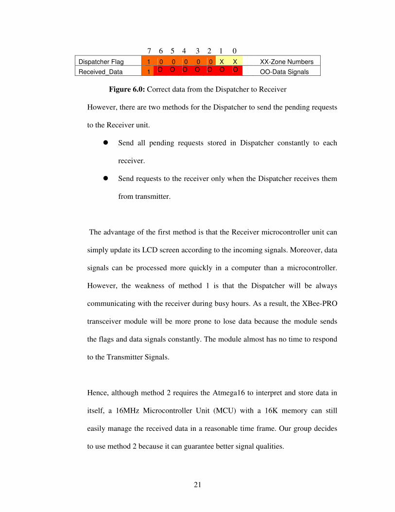
In the beginning, the Receiver unit will check the Dispatcher Flag (see Figure
5.0 below) to determine whether to process the incoming signal. Dispatcher
flags are set to distinguish the incoming signals received from the Dispatcher
and the Transmitters. Also, for the received_data from the dispatcher, bit 7 is
marked as a 1 to indicate this is a signal from Dispatcher.
21
7 6 5 4 3 2 1 0 Dispatcher Flag 1 0 0 0 0 0 X X XX-Zone Numbers
Received_Data 1 O O O O O O O OO-Data Signals
Figure 6.0: Correct data from the Dispatcher to Receiver
However, there are two methods for the Dispatcher to send the pending requests
to the Receiver unit.
� Send all pending requests stored in Dispatcher constantly to each
receiver.
� Send requests to the receiver only when the Dispatcher receives them
from transmitter.
The advantage of the first method is that the Receiver microcontroller unit can
simply update its LCD screen according to the incoming signals. Moreover, data
signals can be processed more quickly in a computer than a microcontroller.
However, the weakness of method 1 is that the Dispatcher will be always
communicating with the receiver during busy hours. As a result, the XBee-PRO
transceiver module will be more prone to lose data because the module sends
the flags and data signals constantly. The module almost has no time to respond
to the Transmitter Signals.
Hence, although method 2 requires the Atmega16 to interpret and store data in
itself, a 16MHz Microcontroller Unit (MCU) with a 16K memory can still
easily manage the received data in a reasonable time frame. Our group decides
to use method 2 because it can guarantee better signal qualities.
22
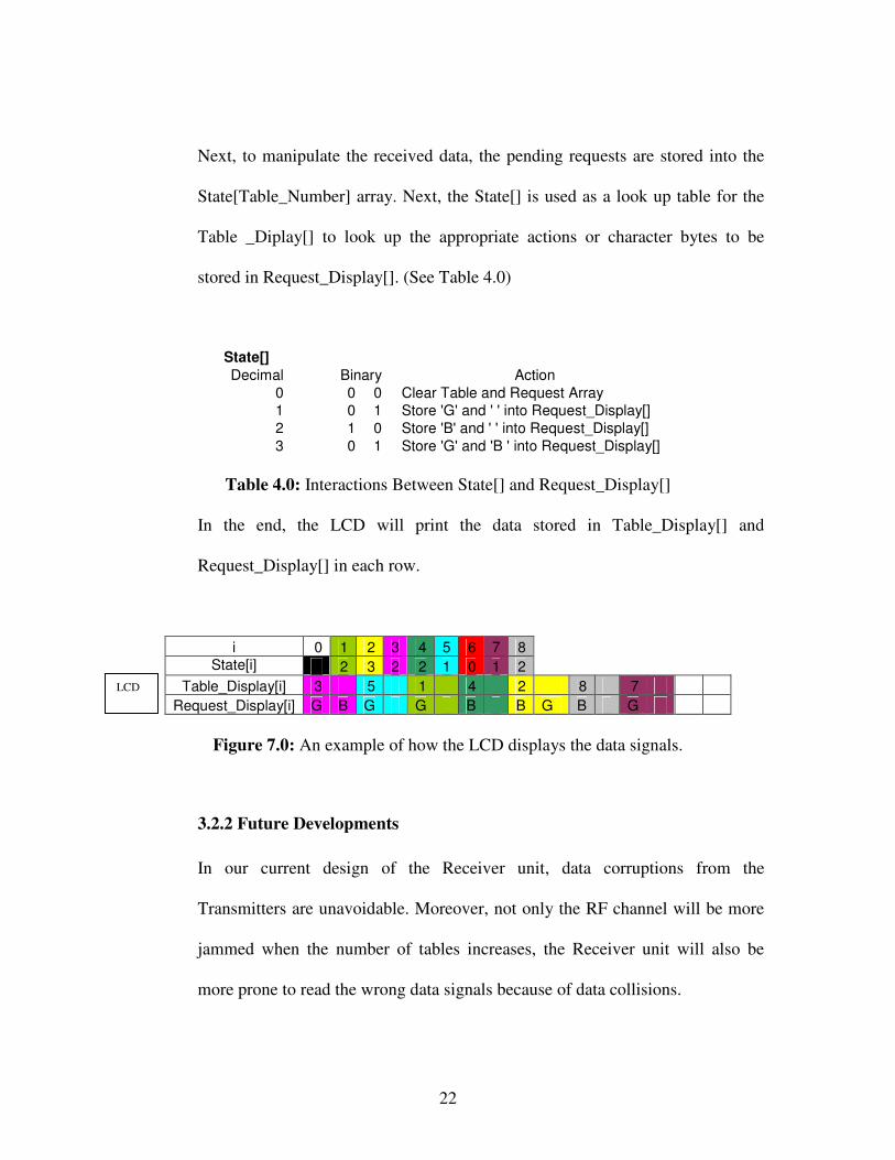
Next, to manipulate the received data, the pending requests are stored into the
State[Table_Number] array. Next, the State[] is used as a look up table for the
Table _Diplay[] to look up the appropriate actions or character bytes to be
stored in Request_Display[]. (See Table 4.0)
State[] Decimal Binary Action
0 0 0 Clear Table and Request Array 1 0 1 Store 'G' and ' ' into Request_Display[] 2 1 0 Store 'B' and ' ' into Request_Display[] 3 0 1 Store 'G' and 'B ' into Request_Display[]
Table 4.0: Interactions Between State[] and Request_Display[]
In the end, the LCD will print the data stored in Table_Display[] and
Request_Display[] in each row.
i 0 1 2 3 4 5 6 7 8 State[i] 2 3 2 2 1 0 1 2
Table_Display[i] 3 5 1 4 2 8 7 Request_Display[i] G B G G B B G B G
Figure 7.0: An example of how the LCD displays the data signals.
3.2.2 Future Developments
In our current design of the Receiver unit, data corruptions from the
Transmitters are unavoidable. Moreover, not only the RF channel will be more
jammed when the number of tables increases, the Receiver unit will also be
more prone to read the wrong data signals because of data collisions.
LCD

23
Therefore, to reduce the possibility of data collisions and corruptions for the
Receiver, data packets should have a larger “value-distance” between them. For
example, the Dispatcher not only sends redundant signals, but also differentiates
the redundant signals by increasing their value-distance (Figure 7.0). The
advantage of this method is that the microcontroller can determine whether the
data signal is corrupted more easily, because of the value-distance.
1 1 1 T T T T T T: Table
T T T T T 0 0 0 T: Table
Figure 8.0: Sample Table Data
Moreover, like the Transmitter module, we can still use the XBee beyond our
prototypes, so that the Receiver can send a confirmation signal to the Dispatcher
to indicate that the message is received.
Another thing to note is that the multiplex switch and function is only
implemented in the prototypes for demonstration. In the actual product, the
Receiver unit should receive data signals for one Zone only.
3.3 THE COMMUNICATIONS PROTOCOL
Designing the Communications Protocol for the System was one of the greatest
challenges since the Transmitter is a transmit-only device and the Receiver is a
receive-only device preventing any form of handshaking. To help remedy this
problem, the Communications Protocol utilizes a UART and a customized signal
format.

24
3.3.1 Universal Asynchronous Receiver Transmitter (UART)
UART, it is a piece of computer hardware that allows the translation between
parallel bits and serial bits. The general data format of each UART
transmission consists of a Start bit, followed by five to eight Data bits (Least
Significant Bit (LSB) first), an optional Parity bit and lastly, an End bit. The
Current design sends eight Data bits and makes use of the Parity bit to aid in
error-prevention.
3.3.2 Signal Format
The eight data bits consist of three types of data (refer to Protocol for more
detailed information):
Bit 7: Source bit [One bit]
� Indicates the Source of Transmission (ie. Transmitter vs Dispatcher)
� 0 = Transmitter, 1 = Dispatcher
Bit 6 – 2: Table bits [Five bits]
� Indicates the Table ID
� Table IDs range from 0 to 31 with Table ID 0 reserved for the
Dispatcher
Bit 1 – 0: Request bits [Two bits]
� Indicates the Request ID
� Two sets of Request IDs are used depending on the preceding Table
ID

25
� Table ID 0 (Dispatcher) ~ Receiver ID ranging from 0 to 3
� Others ~ Service Required: Bit 1 = Bill Request, Bit 0 = General
Request
3.3.3 Protocols
Global Transmission Rule: All data transmissions will be in sets of three made
at random
� Intervals of up to five seconds.
Transmitter:
� All data transmissions will have the Source bit set to 0.
� A transmission is made whenever there is a change in switch state.
� Should there be no change in state within 15 seconds; a
retransmission will be made with the exception of both switches OFF
in which case there will be no transmission.
Dispatcher:
� All data transmissions will have the Source bit set to 1.
� Two bytes of data will be sent:
� First byte: 1 + 00000 + ID of Receiver desired
� Second Byte: 1 + Table ID + Request ID
� Should no signal be received from the Transmitter for 45 seconds, it
will be assumed that both switches are OFF.
Receiver:
26
� A transmission of 1 + 00000 + own ID must be received prior to
accepting any requests.
� Only requests sent by the Dispatcher can be accepted
3.3.4 Obstacles
Transmitter and Dispatcher Transmissions:
Originally it was planned to have Transmitters and Receivers operating on
different channels and the Dispatcher would be the link between the two devices.
After further investigation, it was noted that channel configuration cannot be
changed during real-time operation hence all devices would need to operate on
the same channel. Due to a late arrival of the XBee devices and time constraints,
one major problem was overlooked.
Allowing the Receiver to differentiate between the transmissions is a problem
that was not detected until recently. The Receiver should only acknowledge
transmissions from the Dispatcher but since both the Transmitters and
Dispatchers operate on the same channel and use the same format, incorrect data
received is highly likely. The solution is to add a Source bit to the signal format.
This idea is quite simple however, discovering this bug so late in the project
required many functions to be updated.
3.3.5 Future Developments
Transmitter:

27
Cost can be further reduced by replacing the XBee with a true transmit-only
circuit. The ATMega16 microcontroller could also be replaced with another
microcontroller (such as a PIC) to further reduce costs
Communications Protocol:
Currently, the Communications Protocol supports only eight bit transmissions.
Should additional tables or function switches will be added in the future;
adjustments in either the software or the protocol would be required.
Handshaking is crucial for reliable transmissions. Should costs become feasible,
all devices should include a transceiver in order to provide feedback for
handshaking protocols.
28
4.0 SOFTWARE PROGRAM
The Dispatcher System is written in Java. A Java-development platform is required to
implement the System. The Dispatcher System was created in a platform called Eclipse
version SDK 3.2. Eclipse, along with the Java Runtime Environment (also known as
JRE), provides a user-friendly platform. Both the Eclipse and the JRE is available for
download at http://www.eclipse.org/downloads. To generate the GUI source code in Java,
SWT designer was used. The SWT Designer version must match with the operating
system (OS) and the Eclipse, and it can be downloaded at
http://www.instantiations.com/swt-designer/download_content.html
4.1 MAIN DISPATCHER SYSTEM
The main dispatcher program is a software program that utilizes a personal computer
to accept data via serial port of a wireless receiver, store data, display data on the
screen and redistribute data to the designated receivers.
The software is implemented using Java programming language in the Eclipse
platform, which was designed for building integrated development environments
(IDEs).
The graphical user interface is implemented using Standard Widget Toolkit (SWT), a
software component that delivers native widget functionality for the Eclipse platform
in an operating system independent manner. The GUI display serves three main
features; one, managing table assignments and waiter/waitress status using tables,

29
second, keeping track of waiter/waitress performances, and lastly, notifying cashier
for billing requests.
MySQL, an open source rational database management system (RDBMs) that relies
on structured query language (SQL) for requesting information from a database, is
used in processing data in this dispatcher program.
4.1.1 Graphical User Interface (GUI)
The SWT Designer provides an easy to use environment for creating the GUI.
The source code of the GUI is automatically generated when any graphics was
added to the Java file. The code that is generated contains the properties of each
individual GUI item. Some methods are created to control the entire GUI.
Some methods are implemented to receive signals via serial port of a wireless
receiver and redistribute signals via serial port to designated receiver.
4.1.2 Serial Port
RS-232 is used to communicate between the XBee and the Dispatcher System.
Java itself doesn’t contain any class that communicates with the serial port.
However, Sun Developer Network (SDN) provides an API extension for
communicating with parallel and serial ports, specifically for Windows
environments. The API can be downloaded at http://java.sun.com/products/
javacomm. The Java Communications (a.k.a. javax.comm) API is a proposed
standard extension that enables authors of communications applications to write

30
Java software that accesses communications ports in a platform-independent
way.
It is very important to download the following files from SDN:
� comm.jar
� win32com.dll
� javax.comm.properties
And put these file into these directory:
� comm.jar should be placed in:
%JAVA%/jre/lib/ext
� win32com.dll should be placed in:
%JAVA%/jre/bin
%windows%/System32
� javax.comm.properties should be placed in:
%JAVA%/jre/lib
First, the Dispatcher System must detect the serial port that is connected with
the XBee. After the serial port is located, the port must be identified and
declared ownership by the Java program. Then, whenever there is data arriving
at the serial port, the data will be stored in the buffer, waiting to be accessed.
For the Dispatcher System the following is the serial port parameters:
31
� Baud Rate: 9600
� Data Bits: 8
� Stop Bits: 1
� Parity: None
These settings are the same as it is configured on the XBee.
4.1.3 Database
RDBM is a type database management system (DBM) that stores data in the
form of related tables. There are five tables in the database: temp, request types,
waiters, tables, and request.
1. “Temp”: This table has three columns: arrival time, table id, and type id.
Arrival time indicates the time when main dispatcher program receives
data via serial port of a wireless receiver. Therefore, all incoming data
will temporarily be stored in this table first. The program will then
determine the type of request by type id and add this request to the
request table.
2. “Request Types”: This table has only two columns; type id and request
type. The type id is stored as an integer and request type as a string.
Thus, other methods in the database may retrieve request type string
from an integer input for displaying data on the GUI.
32
3. “Waiters”: This table has four columns: waiter id, waiter first name,
waiter last name, and whether or not the person is in the management
position. When a waiter gets added or deleted to this table, the combo
box on the Tables’ tab will be refreshed to reflect the change.
4. “Tables”: This table has four columns: table id, waiter id, waiter first
name and waiter last name. To add a table assignment, all it needs is the
table id and a waiter id. Waiter first name and last name will
automatically be stored in the table when a waiter id is specified.
5. “Request”: This table has eight columns: request id, arrival time, table id,
request type, status, waiter first name, waiter last name, and waiter id.
Request id is an auto increment integer value assigned to each request.
Arrival time is directly retrieved from the temp table when the
dispatcher program receives a signal. Waiter first name, last name, and
waiter id are retrieved from tables table. Any request that gets added to
the request table will have a “pending” status, only when a task is
completed will have the status changed to “done.”
The following is a Simplified Data Model showing how each table are linked
with each other.

33
Figure 9.0: Simplified Data Model
4.1.4 Data Flow
The data flow of the main dispatcher system can be described by the following
data flow diagram. The main dispatcher system is programmed to receive
signals anytime when a signal is received through the serial port of the wireless
device, not acquiring signals from the serial port. For this reason, the tables in
the database have to be refreshed every few seconds. When the request has
gotten its waiter id, the designated receiver, the main dispatcher program will
send the signal out to the receiver. Two signals will be sent to the receiver, the
first signal sent specifies which receiver to receive the data, and second signal
contains its own table id and the request type id.
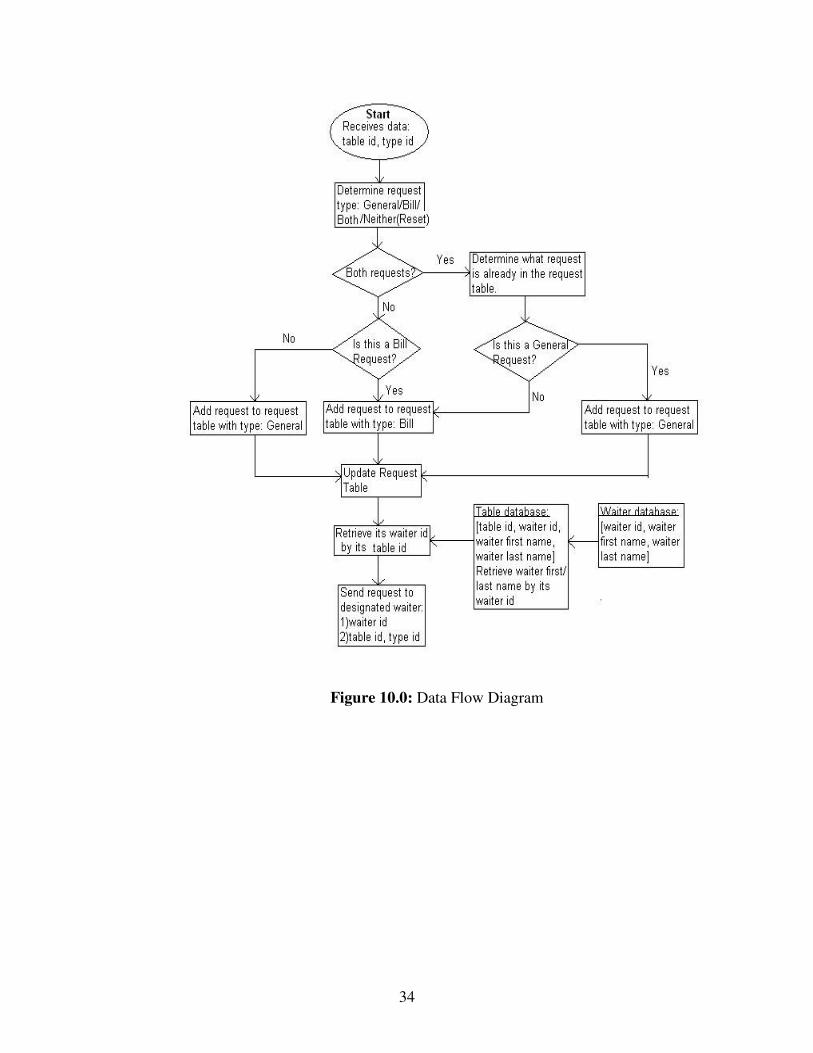
34
Figure 10.0: Data Flow Diagram
35
4.1.5 Functionality
There are three tables displaying on the GUI: Tables, Waiters, and Requests,
each separated by tabs; one for table assignment, the other for waiter/waitress
management, and third one for showing all requests from customers. The first
two tables are mainly for managing purposes and the last table is an aid for the
cashier to keep track of billing requests from customers, and for the store
manager to keep track of waiter/waitress performances.
1. “New” Button: This button only appears in the Tables and Waiters tabs.
It clears the data that is already appearing in the text fields which better
prepares the manager for entering a new waiter/waitress information
and/or table assignment. When this button is pressed, nothing is
modified or added to the database.
2. “Save” Button: This button also, only appears in the Tables and Waiters
tabs. When this button is pressed, the information that is entered into the
text fields gets saved into the database and GUI table refreshes to reflect
the change. This button is to save both new entries and modified entries
to the table.
3. “Delete” Button: This button appears in all three tabs. It is to delete any
single entry or multiple entries in the table. The user must select an
36
entry or pressing the Shift button down simultaneously to select multiple
entries in order to delete it. By pressing the Delete button, data on GUI
and database will be deleted.
4. “Waiter ID” Combo Box: The Waiter ID combo box from the Tables’
tab is a list all the available waiter/waitress in the restaurant, the same
list of waiter Ids as the one in the Waiters table. When a waiter/waitress
gets deleted from or added to the Waiters table, the change will also be
reflected in this list. When making table assignments, the user may
select a desired waiter/waitress, and automatically their first and last
names will be passed on to the Waiter First Name and Waiter Last Name
text fields.
5. “Filtering”: This function allows the user to filter out long entries in the
Requests Table by Waiter Id, Task Status, or Request Type.
6. “Show All” Button: By pressing this button, the user will be allowed to
view the complete Request Table again after filtering. It retrieves all the
entries in the request table database.
7. “Clear Table” Button: This button allows the user to clear Request
Table on GUI and the database. User confirmation is required before
program clears the request table.

37
Figure 11.0: Table Tab Screen Shot
38
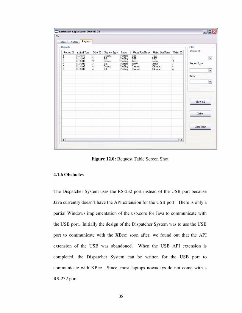
Figure 12.0: Request Table Screen Shot
4.1.6 Obstacles
The Dispatcher System uses the RS-232 port instead of the USB port because
Java currently doesn’t have the API extension for the USB port. There is only a
partial Windows implementation of the usb.core for Java to communicate with
the USB port. Initially the design of the Dispatcher System was to use the USB
port to communicate with the XBee; soon after, we found out that the API
extension of the USB was abandoned. When the USB API extension is
completed, the Dispatcher System can be written for the USB port to
communicate with XBee. Since, most laptops nowadays do not come with a
RS-232 port.
39
4.1.7 Future Developments
The main dispatcher system software may have a few areas to improve on in the
future. The current system allows anyone to view and modify the database.
Adding a user profiles with password will improve the overall security of the
system. As for eccentric feature, colour code different request status, request
type, or waiter id would make the request table easier to read. In the future, it
would be efficient to join this main dispatcher software to the existing ordering
software that restaurants use today to increase the productivity.

40
5.0 TESTING PHASE
5.1 TRANSMITTER
The Transmitter circuit was extensively tested to ensure that component requirements
are met and usage is within specification. Current draw and voltage drop was
measured for every component to determine power consumption and make certain
that sufficient resources are available for proper functionality. Overall current draw
was also used to help determine the battery life of the Transmitter.
Figure 13.0: UART Transmission
To test the output of the microcontroller, its transmissions were extended to 2 seconds
each so that it may be more easily viewed on the oscilloscope. The output of the
microcontroller was first predicted and probed to verify the predictions.

41
Figure 14.0: Switch Bouncing
Lastly, to properly capture a change of state, a denouncer must be implemented. This
component as implemented through the microcontroller. In order to determine the
sampling interval for the denouncer, a switch was connected to the oscilloscope and
repeatedly turned on and off to measure the bouncing. The test was performed fifty
times and the worst case time was used in the program.
5.2 RECEIVER
Our group uses CircuitMaker2000 to simulate the voltage and current flowing
through each component (See Fig 14.0 below). As a result, our team is able to debug
our PCB design more easily.

42
+V
V25V
+V
V12.8V
D1DIODE
R61k
S1C2
3.3uF
C43.3uF
C33.3uF
C13.3uF
IN
COM
OUT
U278L05
IN
COM
OUT
U178L05
+
-
Vs19V
R5150
R43.9k
R368
R133
R2400
0.000us 0.500us 1.000us 1.500us 2.000us 2.500us 3.000us 3.500us 4.000us 4.500us 5.000us
6.000 V
5.000 V
4.000 V
3.000 V
2.000 V
1.000 V
0.000 V
A: u1_1B: r3_2C: r5_2D: r6_1
Figure 15.0: CircuitMaker2000 Schematics and Testing Waveforms
for the Receiver Unit Power Circuit

43
The next thing in the testing list is the LCD module, because the hardware won’t
work unless the software portion works properly. By some simple AVR Studio4
programming, a quick simulation can be achieved using the Hapsim Simulator.
However, during this phase, our group has discovered that the LCD does not have a
clock source. As a result, an external clock is needed to drive the LCD.
CodeVisionAVR would require the users to install an additional crystal oscillator for
Atmega16, but on the other hand, AVR studio can set the internal clock of the chip.
Figure 16.0: Hapsim Simulation of the LCD Display using AVR Studio
44
5.3 MAIN DISPATCHER
This part of the testing phase is done on GUI software. Thus, the software program
must be loaded and running.
5.3.1 The Initial State
After GUI has been loaded and running, it was verified that all text fields in the
program are cleared. Waiter Id Combo Box on the tables tab and Waiter Id
Combo Box on the request table were also empty, since these two combo boxes
are retrieving data from waiters table and no data has yet been stored in the
waiters table. The Status Combo Box on request tab should show “Pending”
and “Done,” Request Type Combo Box should show “General” and “Bill,” and
Management Combo Box should show “Yes” and “No.”
5.3.2 Tables and Waiter Tabs
First, some data must be entered and stored in the waiters table. Fill in all the
text fields and click on Save. The new entry was shown on the waiters table.
Select the entry that was just entered and click on Delete. The selected entry
disappeared from the table. Add more entries into the table accordingly. To test
the New button, select any entry from the table and click on New. All
information that was originally in the text fields should now be cleared. Then,
select a pre-existing entry, make changes in the text fields and click on Save.
The entry was modified and no new entry is being added to the table. The main
45
dispatcher system is programmed so that waiter id and table id are unique.
Therefore, the program will not allow duplicate waiter ids and table ids. Once
there are multiple entries in the waiter table, check if the Waiter ID Combo
Boxes in other tabs reflects the changes. For instance, there were initially five
waiters in the waiters table, the Waiter ID Combo Boxes should have five
entries, after deleting an entry in the waiters table, Waiter ID Combo Boxes
should now have only four entries. It was verified that all these functionalities
work in our dispatcher program.
5.3.3 Request Tabs
To test the request table properly without any incoming signal from an external
source, the “receive” method is called in the main function with inputs. Load
the program again, so that there are some entries already in the request table.
Each filtering methods are tested and changes are reflected in the request table.
The Show All button worked as expected in showing all entries in the request
table. Delete button functionality was tested in the same manner as other delete
buttons in other tabs. The delete confirmation dialogue box popped onto the
screen as expected before data gets deleted from the table.
5.3.4 Testing Request Status
A button was added to the request tab. When clicking on this button, program
will call the “receive” method again with a table id and a request complete
signal that already exists in the request table. The purpose of this step is to

46
verify that the program calculates the time that a waiter/waitress takes to
complete the task, also change the status of the request from pending to done. It
was tested and verified these two functionalities worked properly.
5.3.5 Serial Port
To test if the XBee can communicate with Java, a simple program was written
to open a serial port and read/write on to the port. With the help of this simple
program it shows that XBee and Java can communicate with each other.

47
6.0 CONCLUSION
The purpose of the wireless restaurant management system is to improve worker
efficiency and to maximize profit margin of restaurant owners by providing better service.
Providing prompt response to customers through use of a Transmitter and data collection
by the Main Dispatcher will allow this to happen. This project proved to be a larger task
than expected due to lack of manpower and late arriving parts. Certain functionality also
had to be abandoned to meet time constraints. The System is not designed to replace the
existing ordering systems which are at many restaurants but to complement it. Once the
Restaurant Management System becomes further refined with the ideas discussed in the
previous section, it will pose to be an indispensable tool.

48
APPENDIX A: BUDGET