team dominate(d?) the happy peace bike. defining un-measured variables the variables we decided to...
TRANSCRIPT

Team Dominate(d?)
The Happy Peace Bike

Defining un-measured variables
The variables we decided to characterize are: Acceleration Deceleration Lateral Acceleration Tire temperature Lean angle Suspension travel GPS (time and donations permitting)Although engine speed and velocity are already measured by
standard gauges, we decided to also transmit these data values for correlation with the other acquired data.
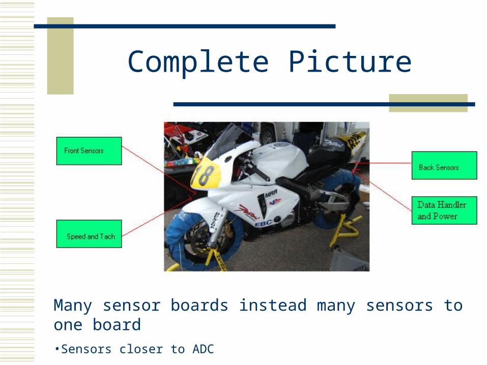
Complete Picture
Many sensor boards instead many sensors to one board•Sensors closer to ADC
•Able to create more extensible system

High-Level Block Diagram
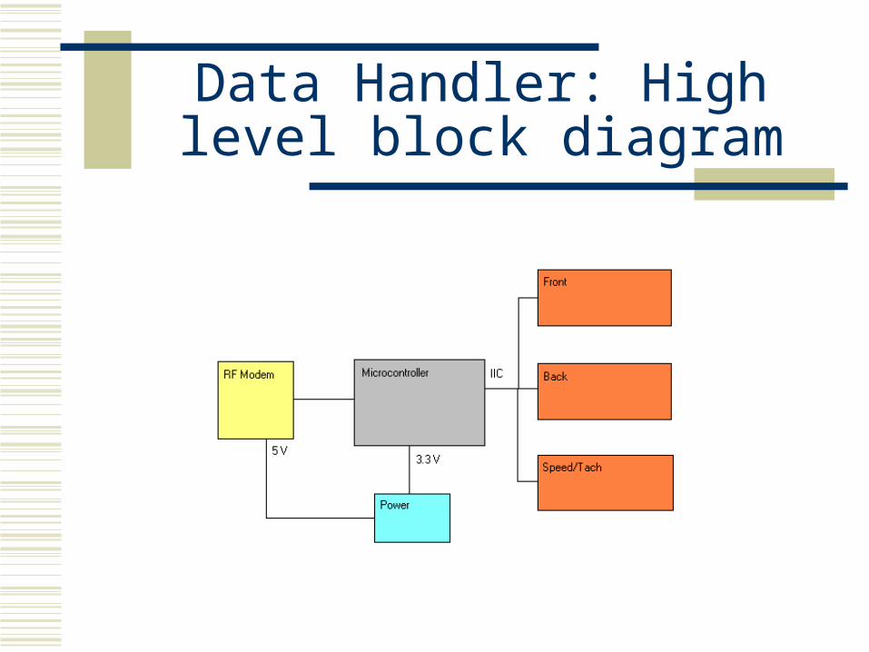
Data Handler: High level block diagram
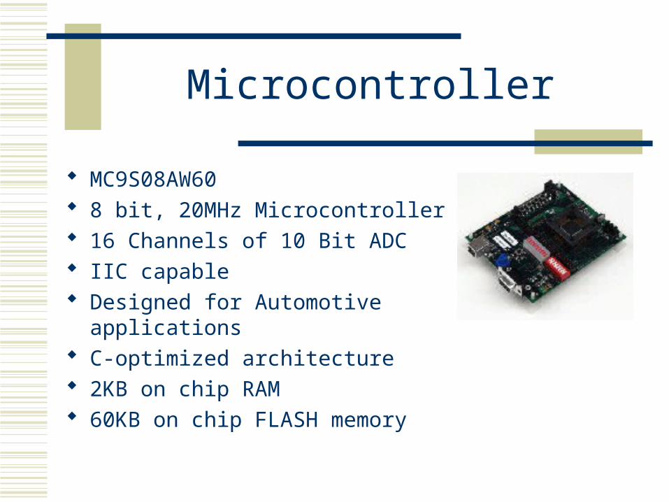
Microcontroller
MC9S08AW60 8 bit, 20MHz Microcontroller 16 Channels of 10 Bit ADC IIC capable Designed for Automotive applications C-optimized architecture 2KB on chip RAM 60KB on chip FLASH memory
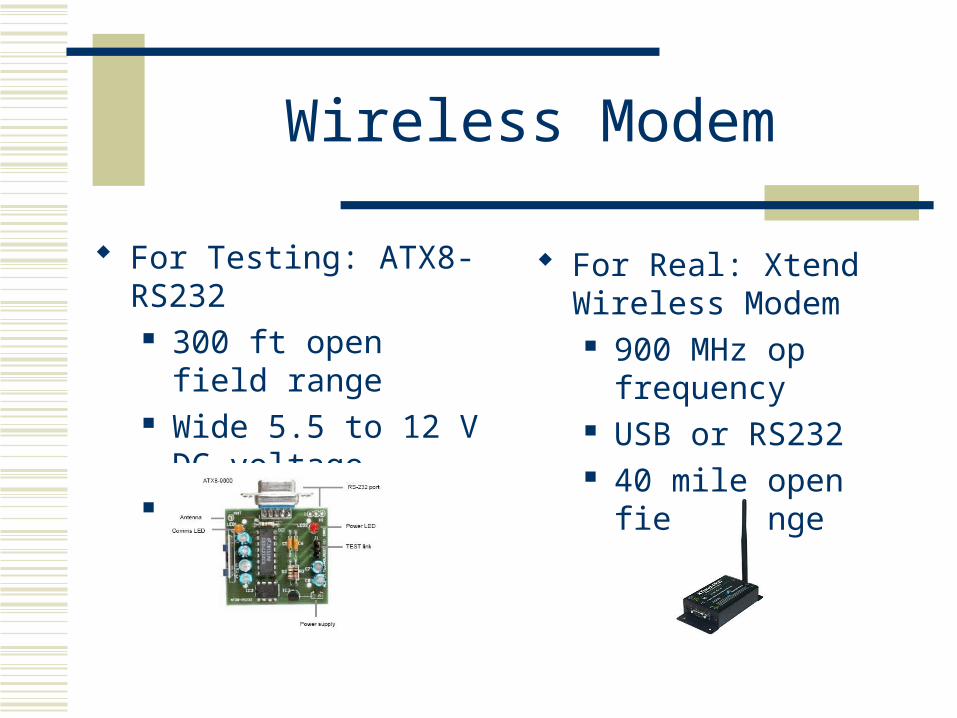
Wireless Modem
For Testing: ATX8-RS232 300 ft open field range Wide 5.5 to 12 V DC
voltage RS232 I/O
For Real: Xtend Wireless Modem 900 MHz op frequency USB or RS232 40 mile open field
range

Data Throughput
Temp = 5 Hz x 16 bits x 2 sensors = 160 bps Accel x,y,z = 20 Hz x 16 bits x 3 axes = 960 bps Travel = 20 Hz x 16 bits x 2 sensors = 640 bps Tach = 20 Hz x 16 bits = 320 bps Speed = 20 Hz x 16 bits = 320 bps TPS = 20 Hz x 16 bits = 320 bps Angle rate = 20 Hz x 16 bits x 2 axes = 640 bps Total = 3360 bps

Data Handler Schematic
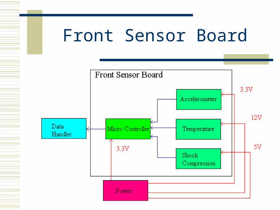
Front Sensor Board

Front Board Schematic
X Accel 1
Y Accel 2
Z Accel 3
ST 4
Vref 5
Y Rate 6
X Rate 7
GND 9
3.3V 9
Vo 1
GND 2
Vcc 3
Front Board
Shock Compression Sensor
Accelerometer
Micro Controller
Vrefh34
Vddad35
Vssad36
Vrefl37
Vdd38
Vss(x2)39
Xtal40
Extal41
BKGD/MS22
ResetBar23
IRQ24
PTGØKBI1PØ25
PTG1/KBI1P126
PTG2/KBI1P227
PTG3/KBI1P328
PTG4/KBI1P429
PTG5/XTAL42
PTG6/EXTAL43
PTFO/TPM1CH219
PTF1/TPM1CH320
PTF2/TPM1CH421
PTF3/TPM1CH532
PTF4/TPM2CH033
PTA0 9
PTA1 10
PTA2 11
PTA3 12
PTA4 15
PTA5 16
PTA6 17
PTA7 18
PTB0/AD1PO 2
PTB1/AD1P1 3
PTB2/AD1P2 4
PTB3/AD1P3 5
PTB4/AD1P4 6
PTB5/AD1P5 7
PTB6/AD1P6 13
PTB7/AD1P7 14
PTC0/SCL1 30
PTC1/SDA1 31
PTC2/MCLK 44
PTC3/TxD2 45
PTC4 1
PTC5/RxD2 1
PTC6 46
PTD0/AD1P8 47
PTD0/AD1P9 48
PTF6/TPM2CH133
PTF633
PTF733
PTD2/AD1P10/KBI1P5 7
PTD3/AD1P11/KBI1P6 8
PTD4/AD1P12/TPM2CLK 9
PTD6/AD1P14/TPM1CLK 10PTD5/AD1P13 11
PTD7/AD1P15/KBI1P7 12
PTE0/TxD1 13
PTE1/RxD1 14
PTE2/TPM1CH0 15
PTE3/TPM1CH1 16
PTE4/SS1BAR 17
PTE5/MISO1 18
PTE6/MOSI1 19
PTE7/SPSCK1 20
10uF
CblkCap
0.1uF
CbyadCap
0.1uF
CbyCap
3.3V
Gnd
5V
Vin 9
GND 10
Vo 11
12V
IICout1
IICout2
0.1uF
Cby1Cap
0.1uF
Cby2Cap
0.1uF
Cby3Cap

Functional Block Diagram
Microcontroller continually polls each analog sensor line
Converts Analog Signal to Digital value
Saves in memory DH accesses memory
location to get value

Tire Temperature Sensors
Tire Temperature Omega OS136
Cost ~ $175 x 2Non-contact IR temperature sensingAccurate reading range 0o-400o FReads 7 measurements per secondAnalog Output 0-5V12V PowerResponse time 150mSec

Sensor Divergence

Accelerometer
IMU 5 Cost ~ $110 Combines 3 axis accelerometer and angle sensor (gyros) Senses Roll and Pitch (Lean angle & wheelie) Senses Acceleration in X, Y, Z axes +/- 3g acceleration range Small size (20x23mm) Analog Output 0.05-3.25V 3.3V Input

Suspension Travel Sensors
Suspension Travel Sharp IR proximity sensor
Cost ~ $12 x 2Measures distance between
fender and fixed mountedpoint of sensor
Specified analog output 3.1V @ 10cm, 0.4V @ 80cm

Sensor DataX-Acceleration (Lateral Force)
Y-Acceleration (Accel/Decel)
Z-Acceleration (“Z Force”)X-Acceleration Faster (Lateral Force)
Y-Acceleration 2 (Accel/Decel)
(all measurements mV vs 10sec increments)
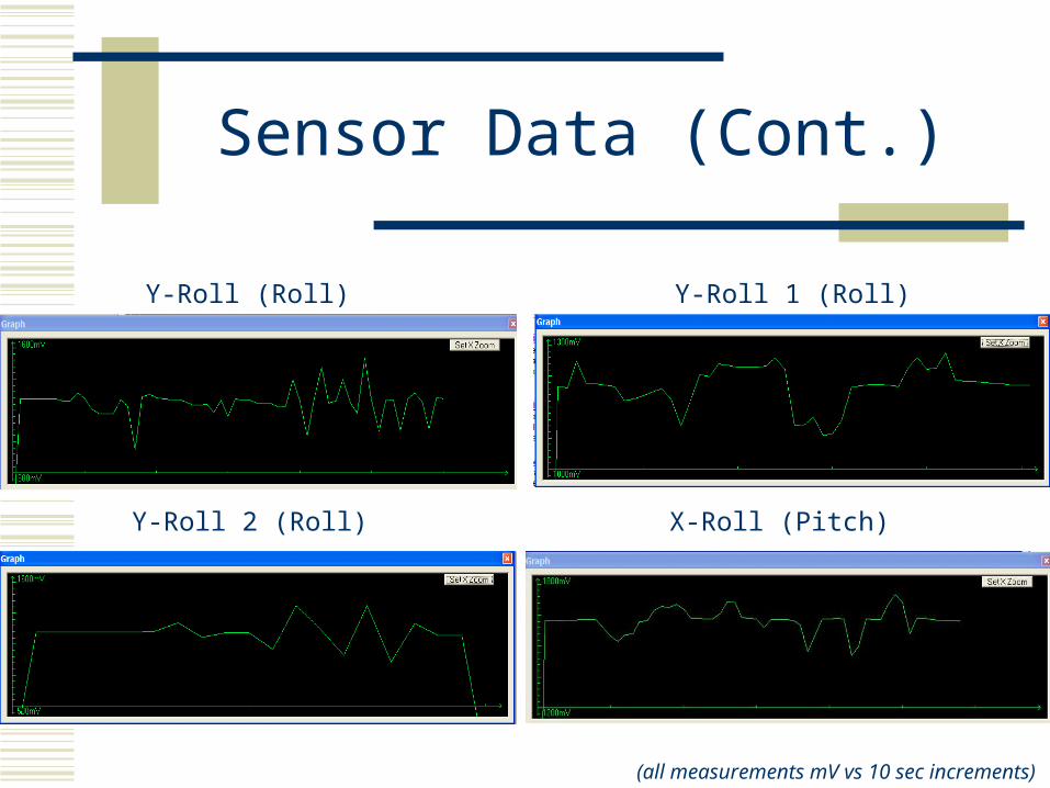
Sensor Data (Cont.)
Y-Roll 1 (Roll)Y-Roll (Roll)
Y-Roll 2 (Roll)
(all measurements mV vs 10 sec increments)
X-Roll (Pitch)

Suspension Travel Data
IR Proximity Sensor (slow)
IR Proximity Sensor (bumps)
(all measurements mV vs 10 sec increments)
(From Manufacturer)

Back Board
GPS (possible)

Back Board Schematic
Vo1
GND2
Vcc3
Back Board
Shock Compression Sensor
Micro Controller
Vrefh34
Vddad35
Vssad36
Vrefl37
Vdd38
Vss(x2)39
Xtal40
Extal41
BKGD/MS22
ResetBar23
IRQ24
PTGØKBI1PØ25
PTG1/KBI1P126
PTG2/KBI1P227
PTG3/KBI1P328
PTG4/KBI1P429
PTG5/XTAL42
PTG6/EXTAL43
PTFO/TPM1CH219
PTF1/TPM1CH320
PTF2/TPM1CH421
PTF3/TPM1CH532
PTF4/TPM2CH033
PTA09
PTA110
PTA211
PTA312
PTA415
PTA516
PTA617
PTA718
PTB0/AD1PO2
PTB1/AD1P13
PTB2/AD1P24
PTB3/AD1P35
PTB4/AD1P46
PTB5/AD1P57
PTB6/AD1P613
PTB7/AD1P714
PTC0/SCL130
PTC1/SDA131
PTC2/MCLK44
PTC3/TxD245
PTC41
PTC5/RxD21
PTC646
PTD0/AD1P847
PTD0/AD1P948
PTF6/TPM2CH133
PTF633
PTF733
PTD2/AD1P10/KBI1P57
PTD3/AD1P11/KBI1P68
PTD4/AD1P12/TPM2CLK9
PTD6/AD1P14/TPM1CLK10
PTD5/AD1P1311
PTD7/AD1P15/KBI1P712
PTE0/TxD113
PTE1/RxD114
PTE2/TPM1CH015
PTE3/TPM1CH116
PTE4/SS1BAR17
PTE5/MISO118
PTE6/MOSI119
PTE7/SPSCK120
10uF
CblkCap
0.1uF
CbyadCap
0.1uF
CbyCap
3.3V
Gnd
5V
Vin9
GND10
Vo11
12V
IICout1
IICout2
0.1uF
Cby1Cap
0.1uF
Cby2Cap
Tire Temperature Sensor

Subsystem specifics: Sensors
Engine Speed/Velocity/Throttle Position/Gear Indicator Found signals generated from OEM sensors were pulse signals with
frequency proportional to speed. OEM sensor pulse will be used as clock input for both microcontroller
counters, set to count-up on each rising edge. External LM555 Timer will be used to generate interrupts for regular
calculation of speed and RPM. Mostly clean square wave with 14.8V Amplitude Some filtering is desired to eliminate the slight noise observed for
clock signal use. TPS is analog signal from 0V – 14.8V proportional to throttle position Signals will need to be scaled for 3.3V input to microcontrollers.

Speedometer
Speed vs. Frequency y = 16.317x + 3.9443
R2 = 0.9999
0
200
400
600
800
1000
1200
1400
0 10 20 30 40 50 60 70 80 90
Speed (M/H)
Fre
qu
en
cy (
Hz)

Tachometer
RPM vs Frequencyy = 0.0333x + 0.568
R2 = 1
0
50
100
150
200
250
300
0 1000 2000 3000 4000 5000 6000 7000 8000 9000
RPM
Fre
qu
en
cy (
Hz)

OEM Sensor Board
OEM Sensor Board
TPS Level Shifter
Micro Controller
Vrefh34
Vddad35
Vssad36
Vrefl37
Vdd38
Vss(x2)39
Xtal40
Extal41
BKGD/MS22
ResetBar23
IRQ24
PTGØKBI1PØ25
PTG1/KBI1P126
PTG2/KBI1P227
PTG3/KBI1P328
PTG4/KBI1P429
PTG5/XTAL42
PTG6/EXTAL43
PTFO/TPM1CH219
PTF1/TPM1CH320
PTF2/TPM1CH421
PTF3/TPM1CH532
PTF4/TPM2CH033
PTA09
PTA110
PTA2 11
PTA312
PTA415
PTA516
PTA6 17
PTA718
PTB0/AD1PO2
PTB1/AD1P1 3
PTB2/AD1P24
PTB3/AD1P35
PTB4/AD1P46
PTB5/AD1P5 7
PTB6/AD1P613
PTB7/AD1P714
PTC0/SCL130
PTC1/SDA131
PTC2/MCLK44
PTC3/TxD245
PTC41
PTC5/RxD21
PTC646
PTD0/AD1P847
PTD0/AD1P948
PTF6/TPM2CH133
PTF633
PTF733
PTD2/AD1P10/KBI1P57
PTD3/AD1P11/KBI1P68
PTD4/AD1P12/TPM2CLK9
PTD6/AD1P14/TPM1CLK10
PTD5/AD1P1311
PTD7/AD1P15/KBI1P712
PTE0/TxD113
PTE1/RxD114
PTE2/TPM1CH015
PTE3/TPM1CH116
PTE4/SS1BAR17
PTE5/MISO118
PTE6/MOSI119
PTE7/SPSCK120
0.1uF
Cbyad
Cap
0.1uF
CbyCap
3.3V
Gnd
IICout1
IICout2
TPS
2.64K
R1
Res11K
R2
Res2
Tach
Speedo
497Ohm
RF1
Res3
497Ohm
RF2
Res4
10pF
CF1
Cap
10pF
CF2
Cap
DZ1
D Zener 3.3
DZ2
D Zener 3.3
Tach Noise Filter and Regulator
Speedo Noise Filter and Regulator
1234
5678
PTimer
555 Timer Chip
1uF
CTime1
Cap
10pF
CTimeBypass
Cap
????K
RB
Res136K
RA
Res1
Timed Interrupt Generator
Power
Power will be derived from the 12 volt DC motorcycle battery (outputs 12V-15V)
Using voltage regulators we will step-down the 12V-15V to 12V, 5V and 3.3V
Board will be attached to Data Handler board with headers to allow for swapping power board easily

Power Schematic
BT1Battery(12-15 V)
Vin Vout
GND
VR1 Volt Reg(12V)
Vin Vout
GND
VR2 Volt Reg( 12V)
Vin Vout
GND
VR3 Volt Reg( 5V)
Vin Vout
GND
VR4 Volt Reg( 5V)
Vin Vout
GND
VR5 Volt Reg( 3.3V)
Vin Vout
GND
VR6 Volt Reg( 3.3V)
10uF
C110uFC2
10uFC3
10uFC4
10uFC5
10uFC6
10uFC7
10uFC8
10uFC9
10uFC10
10uFC11
10uFC12
GND
GND
GND
GND
GND
GND
GND
12345678
P1
H8(outPWR)

Software (computer)
Data will be transmitted in a specific order Data will be read through wireless Data will be converted if needed, Data will be translated and plotted either
through C/C++ or sent to graphing programming

Parts Cost Analysis
Item Description Quantity Price/unit TotalAccel/Angle sensor IMU 5 1 110 110Tire Temp Sensor OS136 2 175 350Susp. Travel sensor Sharp IR Sensor 2 12 24Engine spd. Vel. OEM sensors/decoders 1 20 20TPS OEM sensors/decoders 1 20 20PCB each sensor and data handler 6 33 198RF modem Xbee Xstream 2 300 600Misc parts extra PCB, caps, resistors, etc n/a n/a 100Level Shifter 2 0 05V Regulator LM1805V50 4 2.84 11.363.3V Regulator LM1805V3.3 4 2.84 11.3612V Regulator LT1085V12 4 7.64 30.56Development Board 1 99 99Incrementor 2 0 0Total $ = 1475.28

Division of Labor
Front Board-Mr. Olson Back Board/GPS-Mr. Keogh Power Board and Computer-Mr. Schreiner Data Handler Board-Mr. Pearse Speed/ Tachometer Board/GPS-Mr. OConnell

Milestone 1
Prototype of front board Prototype of back board Basic wireless transmission Prototype of data handler PCB of power board Prototype of speed and tachometer board
Milestone 2
PCB of front board PCB of back board Final revisions of power board Data transmitting from data handler to
computer via wireless
Expo
Display of data presented with computed data values, graphical if possible real time
All boards in final PCB revisions and integrated on the motorcycle

Ghant Chart

Questions??
If duck appears blurry, you may be intoxicated.