tec226x-4(+pir) and tec220x-4(+pir) series lonworks
TRANSCRIPT
TEC226x-4(+PIR) and TEC220x-4(+PIR) Series LONWORKS® Network Staged Thermostat ControllersTechnical Bulletin Code No. LIT-12011611
Issued February 8, 2010
Network Variables (NVs) and Configuration Parameters (CPs) List . . . . . . . . . . . . . 3
Network Variable Inputs (NVIs) Table . . . . . . . . . . . . . . . . . . . . . . . . . . . . . . . . . . . . . . . . 8
Network Variable Outputs (NVOs) Table . . . . . . . . . . . . . . . . . . . . . . . . . . . . . . . . . . . . . 10
Configuration Properties (CPs) . . . . . . . . . . . . . . . . . . . . . . . . . . . . . . . . . . . . . . . . . . . . 13
Space Comfort Controller Object . . . . . . . . . . . . . . . . . . . . . . . . . . . . . . . . . . . . . . . . . . . 18
Commissioning the Thermostat Using a LONWORKS Network Configuration Tool . . . 18
Service Pin . . . . . . . . . . . . . . . . . . . . . . . . . . . . . . . . . . . . . . . . . . . . . . . . . . . . . . . . . . . . . 19
TEC22xx-4 Configuration Plug-in. . . . . . . . . . . . . . . . . . . . . . . . . . . . . . . . . . . . . . . . . . . 19
Installing the Plug-in. . . . . . . . . . . . . . . . . . . . . . . . . . . . . . . . . . . . . . . . . . . . . . . . . . . . . . . 19
Registering the Plug-in. . . . . . . . . . . . . . . . . . . . . . . . . . . . . . . . . . . . . . . . . . . . . . . . . . . . . 20
Using LN Browser to Display NVs, NCIs, and CPs . . . . . . . . . . . . . . . . . . . . . . . . . . . . . . . 22
Running the Plug-in . . . . . . . . . . . . . . . . . . . . . . . . . . . . . . . . . . . . . . . . . . . . . . . . . . . . . . . 27
Heating - Cooling Tab . . . . . . . . . . . . . . . . . . . . . . . . . . . . . . . . . . . . . . . . . . . . . . . . . . . . . . . . . 31
Hardware Tab . . . . . . . . . . . . . . . . . . . . . . . . . . . . . . . . . . . . . . . . . . . . . . . . . . . . . . . . . . . . . . . 32
General Tab . . . . . . . . . . . . . . . . . . . . . . . . . . . . . . . . . . . . . . . . . . . . . . . . . . . . . . . . . . . . . . . . . 33
Model Tab . . . . . . . . . . . . . . . . . . . . . . . . . . . . . . . . . . . . . . . . . . . . . . . . . . . . . . . . . . . . . . . . . . 34
Scheduler Tab . . . . . . . . . . . . . . . . . . . . . . . . . . . . . . . . . . . . . . . . . . . . . . . . . . . . . . . . . . . . . . . 36
Network Tab . . . . . . . . . . . . . . . . . . . . . . . . . . . . . . . . . . . . . . . . . . . . . . . . . . . . . . . . . . . . . . . . 38
About Tab . . . . . . . . . . . . . . . . . . . . . . . . . . . . . . . . . . . . . . . . . . . . . . . . . . . . . . . . . . . . . . . . . . 39
Adding a Thermostat to the Network Automation Engine (NAE) . . . . . . . . . . . . . . . . . 39
LONWORKS Thermostat Controller Mapping . . . . . . . . . . . . . . . . . . . . . . . . . . . . . . . . . . 40
Preparation . . . . . . . . . . . . . . . . . . . . . . . . . . . . . . . . . . . . . . . . . . . . . . . . . . . . . . . . . . . . . 40
Troubleshooting Guide . . . . . . . . . . . . . . . . . . . . . . . . . . . . . . . . . . . . . . . . . . . . . . . . 40
Technical Specifications . . . . . . . . . . . . . . . . . . . . . . . . . . . . . . . . . . . . . . . . . . . . . . 43
TEC226x-4(+PIR) and TEC220x-4(+PIR) Series LONWORKS NetworkStaged Thermostat Controllers . . . . . . . . . . . . . . . . . . . . . . . . . . . . . . . . . . . . . . . . . . . . 43
1TEC226x-4(+PIR) and TEC220x-4(+PIR) Series LONWORKS® Network StagedThermostat Controllers Technical Bulletin

TEC226x-4(+PIR) and TEC220x-4(+PIR) Series LONWORKS® Network Staged Thermostat Controllers Technical Bulletin
2
TEC2
201-
4(+P
IR)
Sing
le S
tage
, Non
Prog
.TE
C226
2-4(
+PIR
)He
at P
ump,
Pro
g.TE
C220
2-4(
+PIR
)He
at P
ump,
Non
Prog
.
X X XX X XX X XX X XX X XN/A X N/AN/A X N/AN/A x N/AN/A x N/A
TEC226x-4(+PIR) and TEC220x-4(+PIR) Series LONWORKS® Network Staged Thermostat ControllersTechnical Bulletin
Network Variables (NVs) and Configuration Parameters (CPs) List
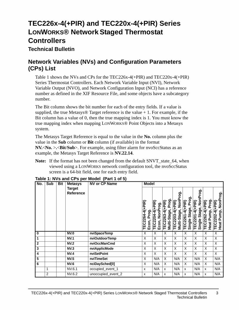
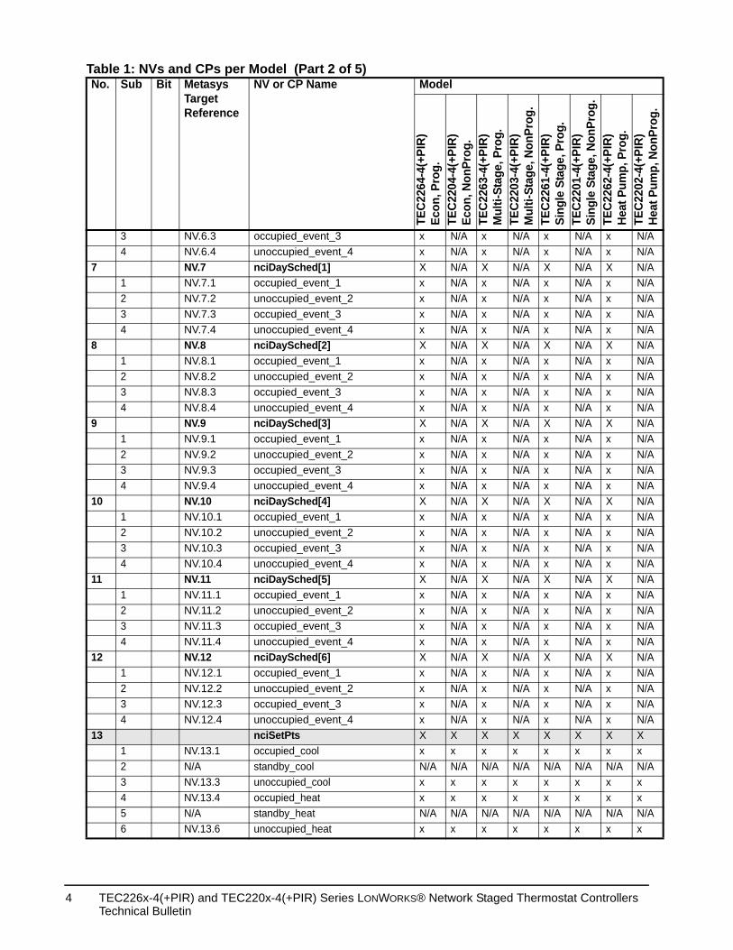
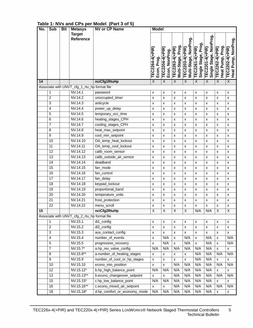
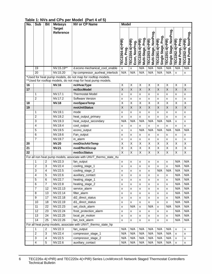
Table 1 shows the NVs and CPs for the TEC226x-4(+PIR) and TEC220x-4(+PIR) Series Thermostat Controllers. Each Network Variable Input (NVI), Network Variable Output (NVO), and Network Configuration Input (NCI) has a reference number as defined in the XIF Resource File, and some objects have a subcategory number.
The Bit column shows the bit number for each of the entry fields. If a value is supplied, the true Metasys® Target reference is the value + 1. For example, if the Bit column has a value of 0, then the true mapping index is 1. You must know the true mapping index when mapping LONWORKS® Point Objects into a Metasys system.
The Metasys Target Reference is equal to the value in the No. column plus the value in the Sub column or Bit column (if available) in the format NV.<No. >.<Bit/Sub>. For example, using filter alarm for nvoSccStatus as an example, the Metasys Target Reference is NV.22.14.
Note: If the format has not been changed from the default SNVT_state_64, when viewed using a LONWORKS network configuration tool, the nvoSccStatus screen is a 64-bit field, one for each entry field.
Table 1: NVs and CPs per Model (Part 1 of 5)No. Sub Bit Metasys
Target Reference
NV or CP Name Model
TEC2
264-
4(+P
IR)
Econ
, Pro
g.TE
C220
4-4(
+PIR
)Ec
on, N
onPr
og.
TEC2
263-
4(+P
IR)
Mul
ti-St
age,
Pro
g.TE
C220
3-4(
+PIR
)M
ulti-
Stag
e, N
onPr
og.
TEC2
261-
4(+P
IR)
Sing
le S
tage
, Pro
g.
0 NV.0 nviSpaceTemp X X X X X1 NV.1 nviOutdoorTemp X X X X X2 NV.2 nviOccManCmd X X X X X3 NV.3 nviApplicMode X X X X X4 NV.4 nviSetPoint X X X X X5 NV.5 nviTimeSet X N/A X N/A X6 NV.6 nciDaySched[0] X N/A X N/A X
1 NV.6.1 occupied_event_1 x N/A x N/A x2 NV.6.2 unoccupied_event_2 x N/A x N/A x
TEC226x-4(+PIR) and TEC220x-4(+PIR) Series LONWORKS® Network Staged Thermostat ControllersTechnical Bulletin
3
N/A x N/AN/A x N/AN/A X N/AN/A x N/AN/A x N/AN/A x N/AN/A x N/AN/A X N/AN/A x N/AN/A x N/AN/A x N/AN/A x N/AN/A X N/AN/A x N/AN/A x N/AN/A x N/AN/A x N/AN/A X N/AN/A x N/AN/A x N/AN/A x N/AN/A x N/AN/A X N/AN/A x N/AN/A x N/AN/A x N/AN/A x N/AN/A X N/AN/A x N/AN/A x N/AN/A x N/AN/A x N/AX X Xx x xN/A N/A N/Ax x xx x xN/A N/A N/Ax x x
TEC2
201-
4(+P
IR)
Sing
le S
tage
, Non
Prog
.TE
C226
2-4(
+PIR
)He
at P
ump,
Pro
g.TE
C220
2-4(
+PIR
)He
at P
ump,
Non
Prog
.
3 NV.6.3 occupied_event_3 x N/A x N/A x4 NV.6.4 unoccupied_event_4 x N/A x N/A x
7 NV.7 nciDaySched[1] X N/A X N/A X1 NV.7.1 occupied_event_1 x N/A x N/A x2 NV.7.2 unoccupied_event_2 x N/A x N/A x3 NV.7.3 occupied_event_3 x N/A x N/A x4 NV.7.4 unoccupied_event_4 x N/A x N/A x
8 NV.8 nciDaySched[2] X N/A X N/A X1 NV.8.1 occupied_event_1 x N/A x N/A x2 NV.8.2 unoccupied_event_2 x N/A x N/A x3 NV.8.3 occupied_event_3 x N/A x N/A x4 NV.8.4 unoccupied_event_4 x N/A x N/A x
9 NV.9 nciDaySched[3] X N/A X N/A X1 NV.9.1 occupied_event_1 x N/A x N/A x2 NV.9.2 unoccupied_event_2 x N/A x N/A x3 NV.9.3 occupied_event_3 x N/A x N/A x4 NV.9.4 unoccupied_event_4 x N/A x N/A x
10 NV.10 nciDaySched[4] X N/A X N/A X1 NV.10.1 occupied_event_1 x N/A x N/A x2 NV.10.2 unoccupied_event_2 x N/A x N/A x3 NV.10.3 occupied_event_3 x N/A x N/A x4 NV.10.4 unoccupied_event_4 x N/A x N/A x
11 NV.11 nciDaySched[5] X N/A X N/A X1 NV.11.1 occupied_event_1 x N/A x N/A x2 NV.11.2 unoccupied_event_2 x N/A x N/A x3 NV.11.3 occupied_event_3 x N/A x N/A x4 NV.11.4 unoccupied_event_4 x N/A x N/A x
12 NV.12 nciDaySched[6] X N/A X N/A X1 NV.12.1 occupied_event_1 x N/A x N/A x2 NV.12.2 unoccupied_event_2 x N/A x N/A x3 NV.12.3 occupied_event_3 x N/A x N/A x4 NV.12.4 unoccupied_event_4 x N/A x N/A x
13 nciSetPts X X X X X1 NV.13.1 occupied_cool x x x x x2 N/A standby_cool N/A N/A N/A N/A N/A3 NV.13.3 unoccupied_cool x x x x x4 NV.13.4 occupied_heat x x x x x5 N/A standby_heat N/A N/A N/A N/A N/A6 NV.13.6 unoccupied_heat x x x x x
Table 1: NVs and CPs per Model (Part 2 of 5)No. Sub Bit Metasys
Target Reference
NV or CP Name Model
TEC2
264-
4(+P
IR)
Econ
, Pro
g.TE
C220
4-4(
+PIR
)Ec
on, N
onPr
og.
TEC2
263-
4(+P
IR)
Mul
ti-St
age,
Pro
g.TE
C220
3-4(
+PIR
)M
ulti-
Stag
e, N
onPr
og.
TEC2
261-
4(+P
IR)
Sing
le S
tage
, Pro
g.
TEC226x-4(+PIR) and TEC220x-4(+PIR) Series LONWORKS® Network Staged Thermostat Controllers Technical Bulletin
4
X X X
x x xx x xx x xx x xx x xx x xx x xx x xx x xx x xx x xx x xx x xx x xx x xx x xx x xx x xx x xx x xx x xx x xN/A X X
x x xx x xx x xN/A x N/AN/A x N/AN/A x xN/A N/A N/AN/A x xN/A N/A N/AN/A x xN/A N/A N/AN/A x xN/A N/A N/AN/A x x
TEC2
201-
4(+P
IR)
Sing
le S
tage
, Non
Prog
.TE
C226
2-4(
+PIR
)He
at P
ump,
Pro
g.TE
C220
2-4(
+PIR
)He
at P
ump,
Non
Prog
.
14 nciCfg1RtuHp X X X X XAssociate with UNVT_cfg_1_rtu_hp format file
1 NV.14.1 password x x x x x2 NV.14.2 unoccupied_timer x x x x x3 NV.14.3 anticycle x x x x x4 NV.14.4 power_up_delay x x x x x5 NV.14.5 temporary_occ_time x x x x x6 NV.14.6 heating_stages_CPH x x x x x7 NV.14.7 cooling_stages_CPH x x x x x8 NV.14.8 heat_max_setpoint x x x x x9 NV.14.9 cool_min_setpoint x x x x x10 NV.14.10 OA_temp_heat_lockout x x x x x11 NV.14.11 OA_temp_cool_lockout x x x x x12 NV.14.12 calib_room_sensor x x x x x13 NV.14.13 calib_outside_air_sensor x x x x x14 NV.14.14 deadband x x x x x15 NV.14.15 fan_mode x x x x x16 NV.14.16 fan_control x x x x x17 NV.14.17 fan_delay x x x x x18 NV.14.18 keypad_lockout x x x x x19 NV.14.19 proportional_band x x x x x20 NV.14.20 temperature_units x x x x x21 NV.14.21 frost_protection x x x x x22 NV.14.22 menu_scroll x x x x x
15 nciCfg2RtuHp X X X X N/AAssociate with UNVT_cfg_2_rtu_hp format file
1 NV.15.1 di1_config x x x x x2 NV.15.2 di2_config x x x x x3 NV.15.3 aux_contact_config x x x x x4 NV.15.4 number_of_events x N/A x N/A x5 NV.15.5 progressive_recovery x N/A x N/A x7 NV.15.7* a.hp_rev_valve_config N/A N/A N/A N/A N/A8 NV.15.8** a.number_of_heating_stages x x x x N/A9 NV.15.9 number_of_cool_or_hp_stages x x x x N/A10 NV.15.10 econo_min_position x x N/A N/A N/A12 NV.15.12* b.hp_high_balance_point N/A N/A N/A N/A N/A13 NV.15.13** b.econo_changeover_setpoint x x N/A N/A N/A15 NV.15.15* c.hp_low_balance_point N/A N/A N/A N/A N/A16 NV.15.16** c.econo_mixed_air_setpoint x x N/A N/A N/A18 NV.15.18* d.hp_comfort_or_economy_mode N/A N/A N/A N/A N/A
Table 1: NVs and CPs per Model (Part 3 of 5)No. Sub Bit Metasys
Target Reference
NV or CP Name Model
TEC2
264-
4(+P
IR)
Econ
, Pro
g.TE
C220
4-4(
+PIR
)Ec
on, N
onPr
og.
TEC2
263-
4(+P
IR)
Mul
ti-St
age,
Pro
g.TE
C220
3-4(
+PIR
)M
ulti-
Stag
e, N
onPr
og.
TEC2
261-
4(+P
IR)
Sing
le S
tage
, Pro
g.
TEC226x-4(+PIR) and TEC220x-4(+PIR) Series LONWORKS® Network Staged Thermostat ControllersTechnical Bulletin
5
N/A N/A N/AN/A x x
X X XX X Xx x xx x xX X XX X Xx x xx x xN/A x xx x xN/A N/A N/Ax x xx x xX X XX X XX X X
x N/A N/Ax N/A N/AN/A N/A N/Ax N/A N/Ax N/A N/Ax N/A N/Ax N/A N/Ax N/A N/Ax N/A N/Ax N/A N/AN/A N/A N/Ax N/A N/Ax N/A N/Ax N/A N/A
N/A x xN/A x xN/A x xN/A x x
TEC2
201-
4(+P
IR)
Sing
le S
tage
, Non
Prog
.TE
C226
2-4(
+PIR
)He
at P
ump,
Pro
g.TE
C220
2-4(
+PIR
)He
at P
ump,
Non
Prog
.
19 NV.15.19** d.econo mechanical_cool_enable x x N/A N/A N/A20 NV.15.20 hp compressor_auxheat_interlock N/A N/A N/A N/A N/A
*Used for heat pump models, do not map for rooftop models.**Used for rooftop models, do not map for heat pump models.16 NV.16 nciHvacType X X X X X17 nciSccModel X X X X X
1 NV.17.1 Thermostat Model x x x x x2 NV.17.2 Software Version x x x x x
18 NV.18 nvoSpaceTemp X X X X X19 nvoUnitStatus X X X X X
1 NV.19.1 mode x x x x x2 NV.19.2 heat_output_primary x x x x x3 NV.19.3 heat_output_secondary N/A N/A N/A N/A N/A4 NV.19.4 cool_output x x x x x5 NV.19.5 econo_output x x N/A N/A N/A6 NV.19.6 Fan_output x x x x x7 NV.19.7 in_alarm x x x x x
20 NV.20 nvoDischAirTemp X X X X X21 NV.21 nvoEffectOccup X X X X X22 nvoSccStatus X X X X XFor all non heat pump models, associate with UNVT_thermo_state_rtu
1 2 NV.22.3 fan_output x x x x x2 3 NV.22.4 cooling_stage_1 x x x x x3 4 NV.22.5 cooling_stage_2 x x x x N/A4 5 NV.22.6 auxiliary_contact x x x x x5 6 NV.22.7 heating_stage_1 x x x x x6 7 NV.22.8 heating_stage_2 x x x x x7 12 NV.22.13 service_alarm x x x x x8 13 NV.22.14 filter_alarm x x x x x9 17 NV.22.18 di2_direct_status x x x x x10 18 NV.22.19 di1_direct_status x x x x x11 22 NV.22.23 set_clock_alarm x N/A x N/A x12 23 NV.22.24 frost_protection_alarm x x x x x13 24 NV.22.25 local_pir_motion x x x x x14 25 NV.22.26 fan_lock_alarm x x x x x
For all heat pump models, associate with UNVT_thermo_state_hp1 2 NV.22.3 fan_output N/A N/A N/A N/A N/A2 3 NV.22.4 compressor_stage_1 N/A N/A N/A N/A N/A3 4 NV.22.5 compressor_stage_2 N/A N/A N/A N/A N/A4 5 NV.22.6 auxiliary_contact N/A N/A N/A N/A N/A
Table 1: NVs and CPs per Model (Part 4 of 5)No. Sub Bit Metasys
Target Reference
NV or CP Name Model
TEC2
264-
4(+P
IR)
Econ
, Pro
g.TE
C220
4-4(
+PIR
)Ec
on, N
onPr
og.
TEC2
263-
4(+P
IR)
Mul
ti-St
age,
Pro
g.TE
C220
3-4(
+PIR
)M
ulti-
Stag
e, N
onPr
og.
TEC2
261-
4(+P
IR)
Sing
le S
tage
, Pro
g.
TEC226x-4(+PIR) and TEC220x-4(+PIR) Series LONWORKS® Network Staged Thermostat Controllers Technical Bulletin
6
N/A x xN/A x xN/A x xN/A x xN/A x xN/A x xN/A x N/AN/A x xN/A x xN/A x xX X XX X XX X XX X XX X XX X XX X Xx x x
TEC2
201-
4(+P
IR)
Sing
le S
tage
, Non
Prog
.TE
C226
2-4(
+PIR
)He
at P
ump,
Pro
g.TE
C220
2-4(
+PIR
)He
at P
ump,
Non
Prog
.
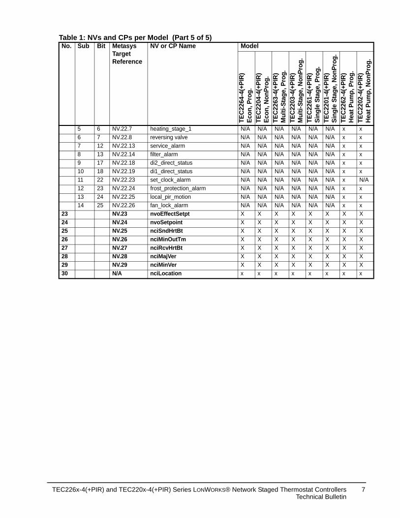
5 6 NV.22.7 heating_stage_1 N/A N/A N/A N/A N/A6 7 NV.22.8 reversing valve N/A N/A N/A N/A N/A7 12 NV.22.13 service_alarm N/A N/A N/A N/A N/A8 13 NV.22.14 filter_alarm N/A N/A N/A N/A N/A9 17 NV.22.18 di2_direct_status N/A N/A N/A N/A N/A10 18 NV.22.19 di1_direct_status N/A N/A N/A N/A N/A11 22 NV.22.23 set_clock_alarm N/A N/A N/A N/A N/A12 23 NV.22.24 frost_protection_alarm N/A N/A N/A N/A N/A13 24 NV.22.25 local_pir_motion N/A N/A N/A N/A N/A14 25 NV.22.26 fan_lock_alarm N/A N/A N/A N/A N/A
23 NV.23 nvoEffectSetpt X X X X X24 NV.24 nvoSetpoint X X X X X25 NV.25 nciSndHrtBt X X X X X26 NV.26 nciMinOutTm X X X X X27 NV.27 nciRcvHrtBt X X X X X28 NV.28 nciMajVer X X X X X29 NV.29 nciMinVer X X X X X30 N/A nciLocation x x x x x
Table 1: NVs and CPs per Model (Part 5 of 5)No. Sub Bit Metasys
Target Reference
NV or CP Name Model
TEC2
264-
4(+P
IR)
Econ
, Pro
g.TE
C220
4-4(
+PIR
)Ec
on, N
onPr
og.
TEC2
263-
4(+P
IR)
Mul
ti-St
age,
Pro
g.TE
C220
3-4(
+PIR
)M
ulti-
Stag
e, N
onPr
og.
TEC2
261-
4(+P
IR)
Sing
le S
tage
, Pro
g.
TEC226x-4(+PIR) and TEC220x-4(+PIR) Series LONWORKS® Network Staged Thermostat ControllersTechnical Bulletin
7
upied mode to be the internal sed. To change the e bind for bound
hermostat. rtBt.
on to the thermostat n outside air sensor ound, or when the matically displays
ys have authority r they are through a
use its own internal l input or onboard
nto different ry node to manually led occupancy.
with any node that unit.rtBt.
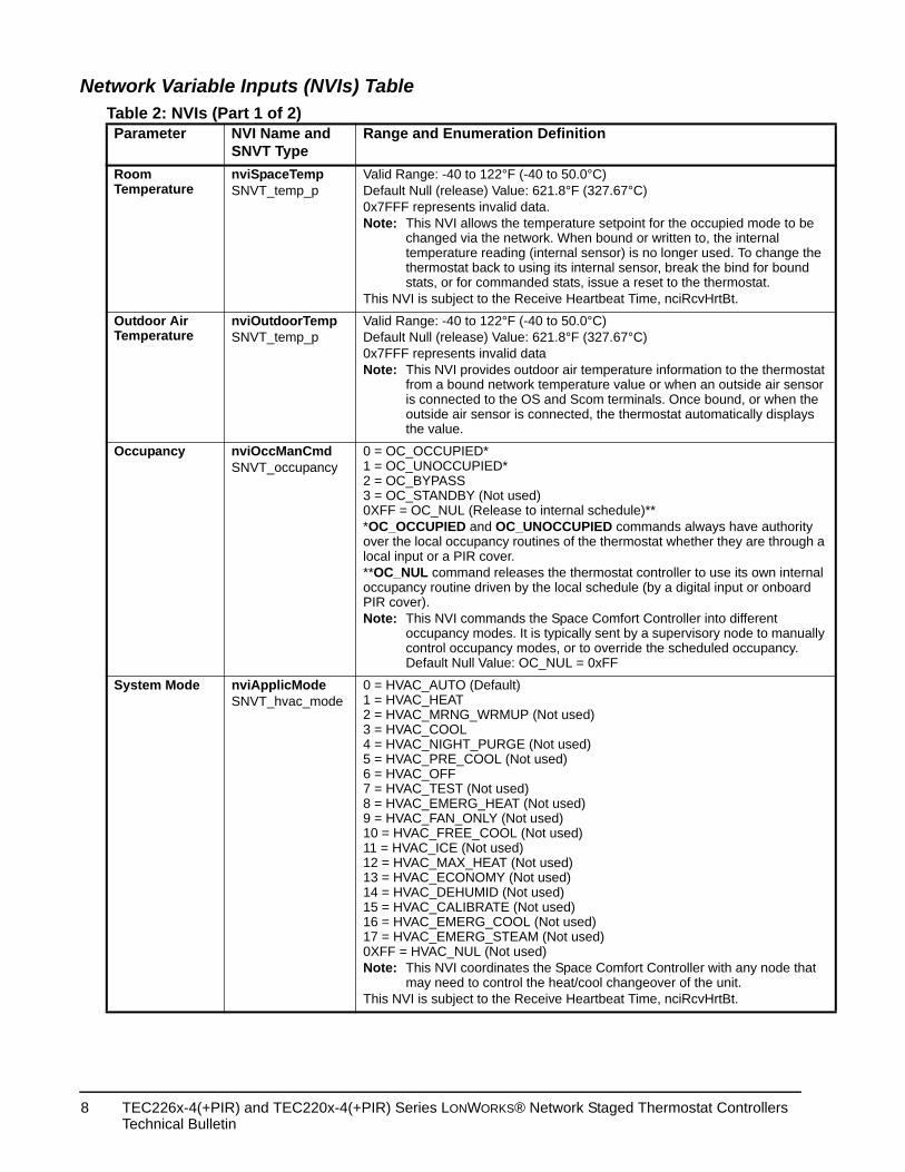
Network Variable Inputs (NVIs) TableTable 2: NVIs (Part 1 of 2)Parameter NVI Name and
SNVT TypeRange and Enumeration Definition
Room Temperature
nviSpaceTempSNVT_temp_p
Valid Range: -40 to 122°F (-40 to 50.0°C)Default Null (release) Value: 621.8°F (327.67°C)0x7FFF represents invalid data.Note: This NVI allows the temperature setpoint for the occ
changed via the network. When bound or written to,temperature reading (internal sensor) is no longer uthermostat back to using its internal sensor, break thstats, or for commanded stats, issue a reset to the t
This NVI is subject to the Receive Heartbeat Time, nciRcvH
Outdoor Air Temperature
nviOutdoorTempSNVT_temp_p
Valid Range: -40 to 122°F (-40 to 50.0°C)Default Null (release) Value: 621.8°F (327.67°C)0x7FFF represents invalid dataNote: This NVI provides outdoor air temperature informati
from a bound network temperature value or when ais connected to the OS and Scom terminals. Once boutside air sensor is connected, the thermostat autothe value.
Occupancy nviOccManCmdSNVT_occupancy
0 = OC_OCCUPIED*1 = OC_UNOCCUPIED*2 = OC_BYPASS3 = OC_STANDBY (Not used)0XFF = OC_NUL (Release to internal schedule)***OC_OCCUPIED and OC_UNOCCUPIED commands alwaover the local occupancy routines of the thermostat whethelocal input or a PIR cover. **OC_NUL command releases the thermostat controller to occupancy routine driven by the local schedule (by a digitaPIR cover).Note: This NVI commands the Space Comfort Controller i
occupancy modes. It is typically sent by a supervisocontrol occupancy modes, or to override the scheduDefault Null Value: OC_NUL = 0xFF
System Mode nviApplicModeSNVT_hvac_mode
0 = HVAC_AUTO (Default)1 = HVAC_HEAT2 = HVAC_MRNG_WRMUP (Not used)3 = HVAC_COOL4 = HVAC_NIGHT_PURGE (Not used)5 = HVAC_PRE_COOL (Not used)6 = HVAC_OFF7 = HVAC_TEST (Not used)8 = HVAC_EMERG_HEAT (Not used)9 = HVAC_FAN_ONLY (Not used)10 = HVAC_FREE_COOL (Not used)11 = HVAC_ICE (Not used)12 = HVAC_MAX_HEAT (Not used)13 = HVAC_ECONOMY (Not used)14 = HVAC_DEHUMID (Not used)15 = HVAC_CALIBRATE (Not used)16 = HVAC_EMERG_COOL (Not used)17 = HVAC_EMERG_STEAM (Not used)0XFF = HVAC_NUL (Not used)Note: This NVI coordinates the Space Comfort Controller
may need to control the heat/cool changeover of theThis NVI is subject to the Receive Heartbeat Time, nciRcvH
TEC226x-4(+PIR) and TEC220x-4(+PIR) Series LONWORKS® Network Staged Thermostat Controllers Technical Bulletin
8
)
cupied mode to be are not changed. ints (for example, t) is overridden, the
sted by the een the two
alue
ce Comfort
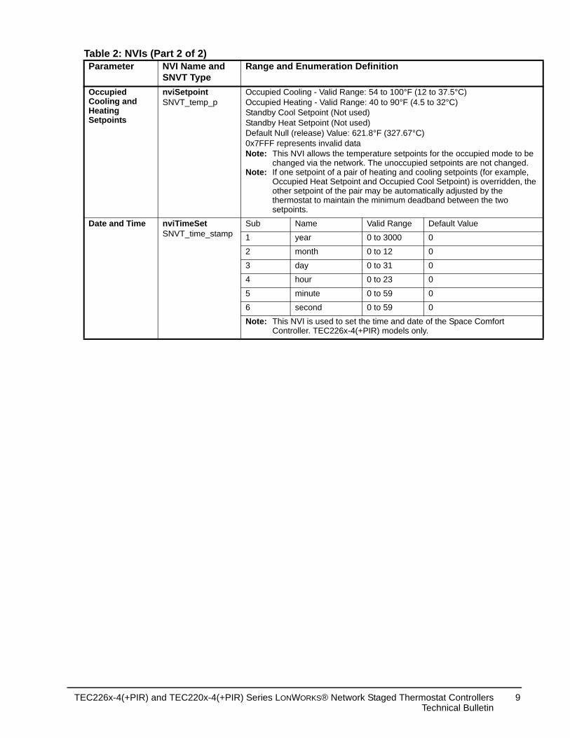
Occupied Cooling and Heating Setpoints
nviSetpointSNVT_temp_p
Occupied Cooling - Valid Range: 54 to 100°F (12 to 37.5°COccupied Heating - Valid Range: 40 to 90°F (4.5 to 32°C)Standby Cool Setpoint (Not used)Standby Heat Setpoint (Not used)Default Null (release) Value: 621.8°F (327.67°C)0x7FFF represents invalid dataNote: This NVI allows the temperature setpoints for the oc
changed via the network. The unoccupied setpointsNote: If one setpoint of a pair of heating and cooling setpo
Occupied Heat Setpoint and Occupied Cool Setpoinother setpoint of the pair may be automatically adjuthermostat to maintain the minimum deadband betwsetpoints.
Date and Time nviTimeSetSNVT_time_stamp
Sub Name Valid Range Default V
1 year 0 to 3000 0
2 month 0 to 12 0
3 day 0 to 31 0
4 hour 0 to 23 0
5 minute 0 to 59 0
6 second 0 to 59 0
Note: This NVI is used to set the time and date of the SpaController. TEC226x-4(+PIR) models only.
Table 2: NVIs (Part 2 of 2)Parameter NVI Name and
SNVT TypeRange and Enumeration Definition
TEC226x-4(+PIR) and TEC220x-4(+PIR) Series LONWORKS® Network Staged Thermostat ControllersTechnical Bulletin
9
re sensor that This output sor failure, the
an invalid value.
P (Not used)
(Not used)ot used)
ot used)_HEAT
t used)t used)
d (Not used)
tatus. It ating and resent in the
erature. In the .67°C or
connected to
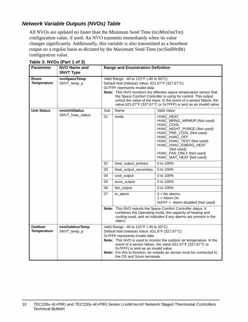
Network Variable Outputs (NVOs) TableAll NVOs are updated no faster than the Minimum Send Time (nciMinOutTm) configuration value, if used. An NVO transmits immediately when its value changes significantly. Additionally, this variable is also transmitted as a heartbeat output on a regular basis as dictated by the Maximum Send Time (nciSndHrtBt) configuration value. Table 3: NVOs (Part 1 of 3)Parameter NVO Name and
SNVT TypeRange and Enumeration Definition
Room Temperature
nvoSpaceTempSNVT_temp_p
Valid Range: -40 to 122°F (-40 to 50°C)Default Null (release) Value: 621.07°F (327.67°C)0x7FFF represents invalid data.Note: This NVO monitors the effective space temperatu
the Space Comfort Controller is using for control.echos the value of the input. In the event of a senvalue 621.07°F (327.67°C or 0x7FFF) is sent as
Unit Status nvoUnitStatusSNVT_hvac_status
Sub Name Valid Value
01 mode HVAC_HEATHVAC_MRNG_WRMUHVAC_COOLHVAC_NIGHT_PURGEHVAC_PRE_COOL (NHVAC_HVAC_OFFHVAC_HVAC_TEST (NHVAC_HVAC_EMERG (Not used)HVAC_FAN_ONLY (NoHVAC_MAX_HEAT (No
02 heat_output_primary 0 to 100%
03 heat_output_secondary 0 to 100%
04 cool_output 0 to 100%
05 econ_output 0 to 100%
06 fan_output 0 to 100%
07 In_alarm 0 = No alarms1 = Alarm On0xFFF = Alarm disable
Note: This NVO reports the Space Comfort Controller scombines the Operating mode, the capacity of hecooling used, and an indicates if any alarms are pobject.
Outdoor Temperature
nvoOutdoorTempSNVT_temp_p
Valid Range: -40 to 122°F (-40 to 50°C)Default Null (release) Value: 621.8°F (327.67°C)0x7FFF represents invalid dataNote: This NVO is used to monitor the outdoor air temp
event of a sensor failure, the value 621.07°F (3270x7FFF) is sent as an invalid value.
Note: For this to function, an outside air sensor must bethe OS and Scom terminals.
TEC226x-4(+PIR) and TEC220x-4(+PIR) Series LONWORKS® Network Staged Thermostat Controllers Technical Bulletin
10
he air that t of a sensor is sent as an
onnected to the
md or a local r the duration of either a ManCmd. This
unit. The ontroller or
coordinate _NUL = 0xFF
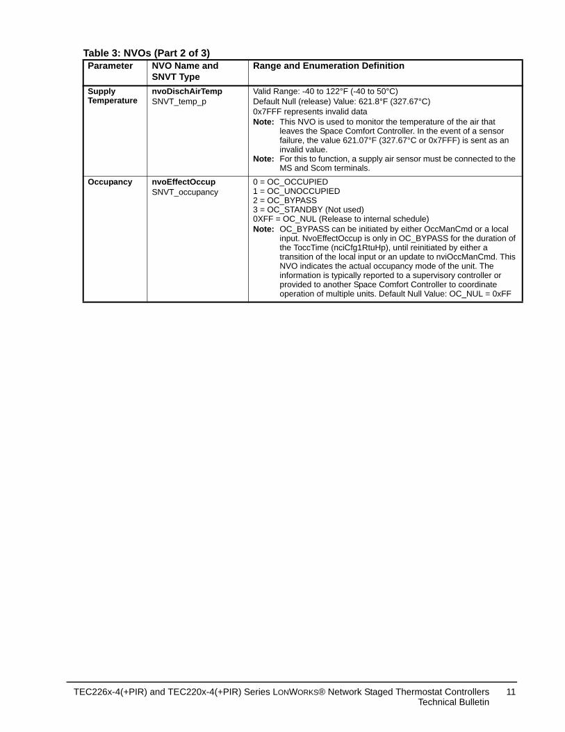
Supply Temperature
nvoDischAirTempSNVT_temp_p
Valid Range: -40 to 122°F (-40 to 50°C)Default Null (release) Value: 621.8°F (327.67°C)0x7FFF represents invalid dataNote: This NVO is used to monitor the temperature of t
leaves the Space Comfort Controller. In the evenfailure, the value 621.07°F (327.67°C or 0x7FFF)invalid value.
Note: For this to function, a supply air sensor must be cMS and Scom terminals.
Occupancy nvoEffectOccupSNVT_occupancy
0 = OC_OCCUPIED1 = OC_UNOCCUPIED2 = OC_BYPASS3 = OC_STANDBY (Not used)0XFF = OC_NUL (Release to internal schedule)Note: OC_BYPASS can be initiated by either OccManC
input. NvoEffectOccup is only in OC_BYPASS fothe ToccTime (nciCfg1RtuHp), until reinitiated bytransition of the local input or an update to nviOccNVO indicates the actual occupancy mode of theinformation is typically reported to a supervisory cprovided to another Space Comfort Controller to operation of multiple units. Default Null Value: OC
Table 3: NVOs (Part 2 of 3)Parameter NVO Name and
SNVT TypeRange and Enumeration Definition
TEC226x-4(+PIR) and TEC220x-4(+PIR) Series LONWORKS® Network Staged Thermostat ControllersTechnical Bulletin
11
Value
t Controller’s
ature setpoint, up, nviSetpoint, f the occupancy t, the effective g setpoint
int.
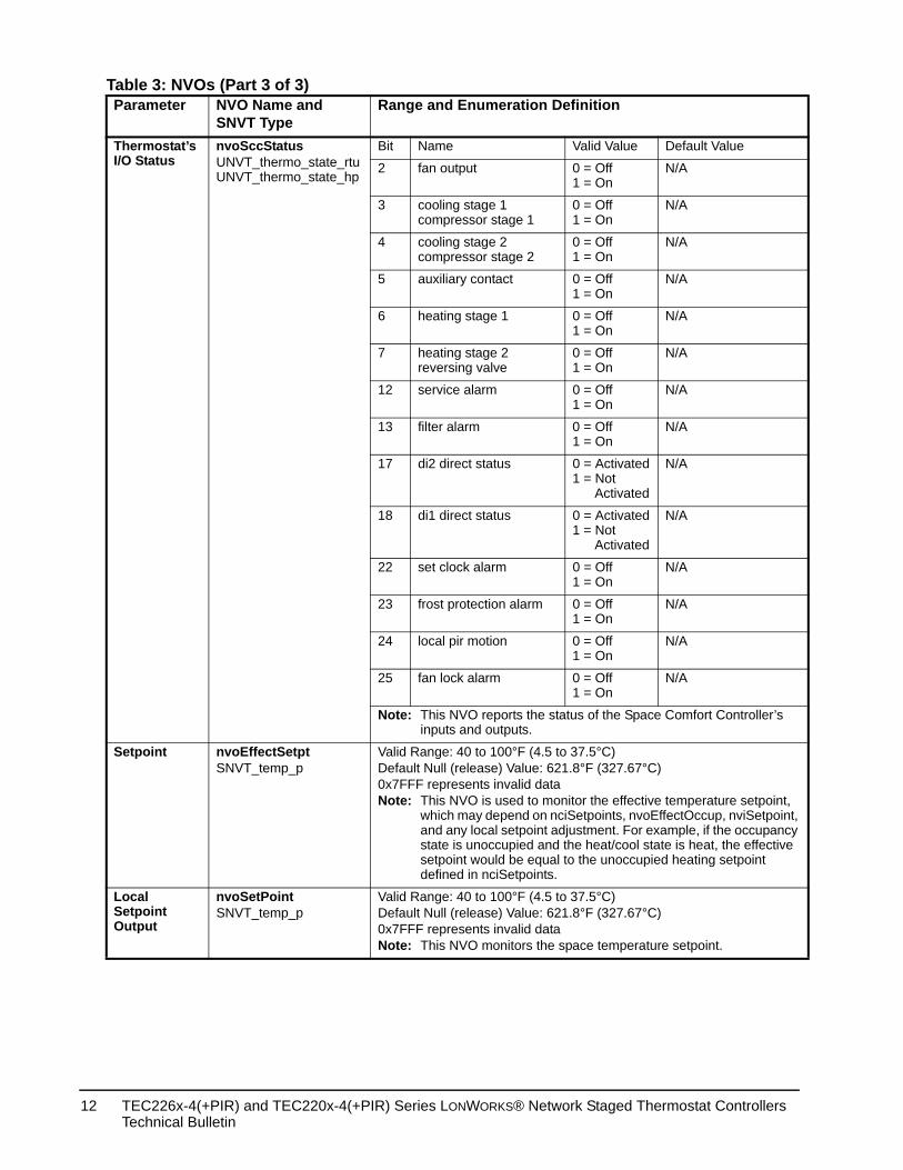
Thermostat’s I/O Status
nvoSccStatusUNVT_thermo_state_rtuUNVT_thermo_state_hp
Bit Name Valid Value Default
2 fan output 0 = Off1 = On
N/A
3 cooling stage 1compressor stage 1
0 = Off1 = On
N/A
4 cooling stage 2compressor stage 2
0 = Off1 = On
N/A
5 auxiliary contact 0 = Off1 = On
N/A
6 heating stage 1 0 = Off1 = On
N/A
7 heating stage 2reversing valve
0 = Off1 = On
N/A
12 service alarm 0 = Off1 = On
N/A
13 filter alarm 0 = Off1 = On
N/A
17 di2 direct status 0 = Activated1 = Not Activated
N/A
18 di1 direct status 0 = Activated1 = Not Activated
N/A
22 set clock alarm 0 = Off1 = On
N/A
23 frost protection alarm 0 = Off1 = On
N/A
24 local pir motion 0 = Off1 = On
N/A
25 fan lock alarm 0 = Off1 = On
N/A
Note: This NVO reports the status of the Space Comforinputs and outputs.
Setpoint nvoEffectSetptSNVT_temp_p
Valid Range: 40 to 100°F (4.5 to 37.5°C)Default Null (release) Value: 621.8°F (327.67°C)0x7FFF represents invalid dataNote: This NVO is used to monitor the effective temper
which may depend on nciSetpoints, nvoEffectOccand any local setpoint adjustment. For example, istate is unoccupied and the heat/cool state is heasetpoint would be equal to the unoccupied heatindefined in nciSetpoints.
Local Setpoint Output
nvoSetPointSNVT_temp_p
Valid Range: 40 to 100°F (4.5 to 37.5°C)Default Null (release) Value: 621.8°F (327.67°C)0x7FFF represents invalid dataNote: This NVO monitors the space temperature setpo
Table 3: NVOs (Part 3 of 3)Parameter NVO Name and
SNVT TypeRange and Enumeration Definition
TEC226x-4(+PIR) and TEC220x-4(+PIR) Series LONWORKS® Network Staged Thermostat Controllers Technical Bulletin
12
nts variable.mple, s +
eek (from ed with the
lt Value
24°C)
26.5°C)
22°C)
16.5°C)
r various
by the e.
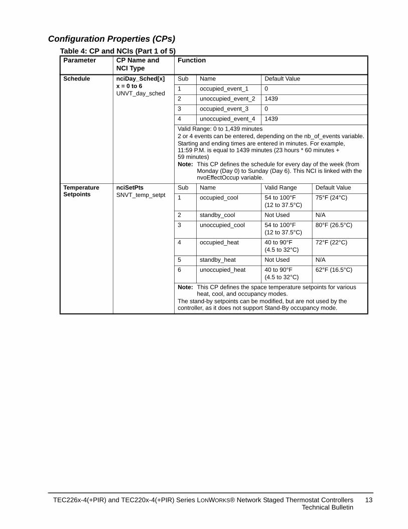
Configuration Properties (CPs) Table 4: CP and NCIs (Part 1 of 5)Parameter CP Name and
NCI TypeFunction
Schedule nciDay_Sched[x]x = 0 to 6UNVT_day_sched
Sub Name Default Value
1 occupied_event_1 0
2 unoccupied_event_2 1439
3 occupied_event_3 0
4 unoccupied_event_4 1439
Valid Range: 0 to 1,439 minutes2 or 4 events can be entered, depending on the nb_of_eveStarting and ending times are entered in minutes. For exa11:59 P.M. is equal to 1439 minutes (23 hours * 60 minute59 minutes)Note: This CP defines the schedule for every day of the w
Monday (Day 0) to Sunday (Day 6). This NCI is linknvoEffectOccup variable.
Temperature Setpoints
nciSetPtsSNVT_temp_setpt
Sub Name Valid Range Defau
1 occupied_cool 54 to 100°F(12 to 37.5°C)
75°F (
2 standby_cool Not Used N/A
3 unoccupied_cool 54 to 100°F(12 to 37.5°C)
80°F (
4 occupied_heat 40 to 90°F(4.5 to 32°C)
72°F (
5 standby_heat Not Used N/A
6 unoccupied_heat 40 to 90°F(4.5 to 32°C)
62°F (
Note: This CP defines the space temperature setpoints foheat, cool, and occupancy modes.
The stand-by setpoints can be modified, but are not used controller, as it does not support Stand-By occupancy mod
TEC226x-4(+PIR) and TEC220x-4(+PIR) Series LONWORKS® Network Staged Thermostat ControllersTechnical Bulletin
13
lt Value
urs
tes
.
rs
)
)
)
)
f
ckout
)
f
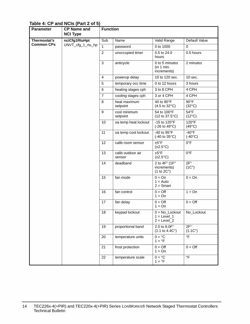
Thermostat’s Common CPs
nciCfg1RtuHptUNVT_cfg_1_rtu_hp
Sub Name Valid Range Defau
1 password 0 to 1000 0
2 unoccupied timer 0.5 to 24.0 hours
0.5 ho
3 anticycle 0 to 5 minutes (in 1 min. increments)
2 minu
4 powerup delay 10 to 120 sec. 10 sec
5 temporary occ time 0 to 12 hours 3 hou
6 heating stages cph 3 to 8 CPH 4 CPH
7 cooling stages cph 3 or 4 CPH 4 CPH
8 heat maximum setpoint
40 to 90°F(4.5 to 32°C)
90°F(32°C
9 cool minimum setpoint
54 to 100°F(12 to 37.5°C)
54°F(12°C
10 oa temp heat lockout -15 to 120°F(-26 to 49°C)
120°F(49°C
11 oa temp cool lockout -40 to 95°F(-40 to 35°C)
-40°F(-40°C
12 calib room sensor ±5°F(±2.5°C)
0°F
13 calib outdoor air sensor
±5°F(±2.5°C)
0°F
14 deadband 2 to 4F° (1F° increments)(1 to 2C°)
2F°(1C°)
15 fan mode 0 = On1 = Auto2 = Smart
0 = On
16 fan control 0 = Off1 = On
1 = On
17 fan delay 0 = Off1 = On
0 = Of
18 keypad lockout 0 = No_Lockout1 = Level_12 = Level_2
No_Lo
19 proportional band 2.0 to 8.0F°(1.1 to 4.4C°)
2F°(1.1C°
20 temperature units 0 = °C1 = °F
°F
21 frost protection 0 = Off1 = On
0 = Of
22 temperature scale 0 = °C1 = °F
°F
Table 4: CP and NCIs (Part 2 of 5)Parameter CP Name and
NCI TypeFunction
TEC226x-4(+PIR) and TEC220x-4(+PIR) Series LONWORKS® Network Staged Thermostat Controllers Technical Bulletin
14
lt Value
ne
ne
ff
C)
C)
F°C)
C)
mfort
f
f
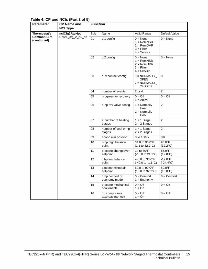
Thermostat’s Common CPs (continued)
nciCfg2RtuHptUNVT_cfg_2_rtu_hp
Sub Name Valid Range Defau
01 di1 config 0 = None1 = RemNSB2 = RemOVR3 = Filter4 = Service
0 = No
02 di2 config 0 = None1 = RemNSB2 = RemOVR3 = Filter4 = Service
0 = No
03 aux contact config 0 = NORMALLY_ OPEN2 = NORMALLY_ CLOSED
0
04 number of events 2 or 4 2
05 progressive recovery 0 = Off1 = Active
0 = O
06 a.hp rev valve config 1 = Normally Heat2 = Normally Cool
2
07 a.number of heating stages
1 = 1 Stage2 = 2 Stages
2
08 number of cool or hp stages
1 = 1 Stage2 = 2 Stages
2
09 econo min position 0 to 100% 0%
10 b.hp high balance point
34.0 to 90.0°F(1.1 to 32.2°C)
90.0°F(32.2°
11 b.econo changeover setpoint
14 to 70°F(-10.0 to 21.1°C)
55.0°F(12.8°
12 c.hp low balance point
-40.0 to 30.0°F(-40.0 to -1.1°C)
-12.0°(-24.4
13 c.econo mixed air setpoint
50.0 to 90.0°F(10.0 to 32.2°C)
50.0°F(10.0°
14 d.hp comfort or economy mode
0 = Comfort1 = Economy
0 = Co
15 d.econo mechanical cool enable
0 = Off1 = On
0 = Of
16 hp compressor auxheat interlock
0 = Off1 = On
0 = Of
Table 4: CP and NCIs (Part 3 of 5)Parameter CP Name and
NCI TypeFunction
TEC226x-4(+PIR) and TEC220x-4(+PIR) Series LONWORKS® Network Staged Thermostat ControllersTechnical Bulletin
15
nt being
lt Value
ds on the l used
ostat dent
ftware
eat
xpires ed.
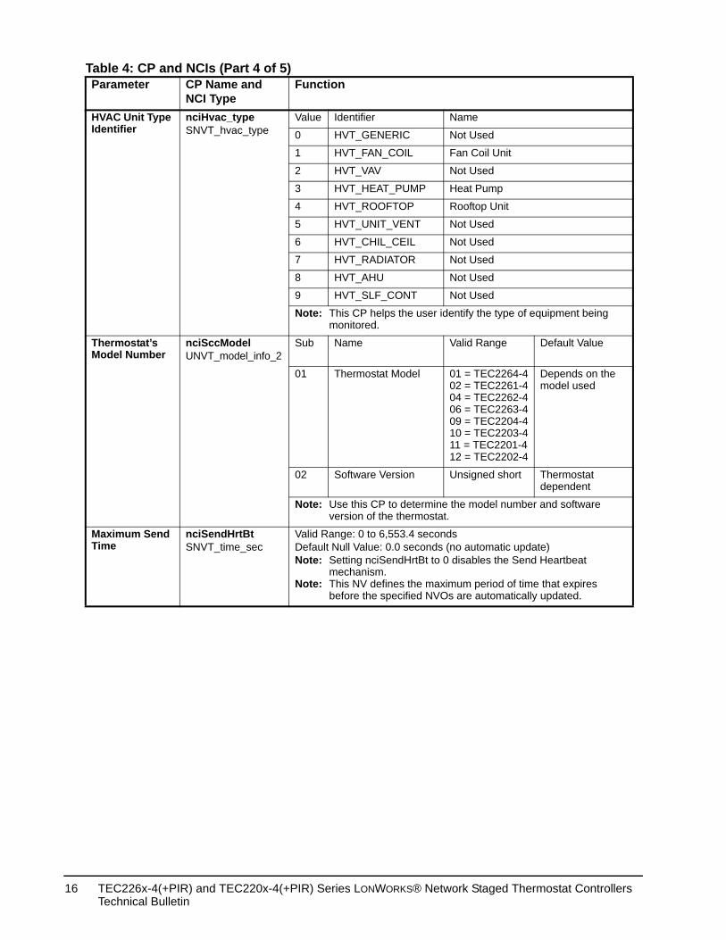
HVAC Unit Type Identifier
nciHvac_typeSNVT_hvac_type
Value Identifier Name
0 HVT_GENERIC Not Used
1 HVT_FAN_COIL Fan Coil Unit
2 HVT_VAV Not Used
3 HVT_HEAT_PUMP Heat Pump
4 HVT_ROOFTOP Rooftop Unit
5 HVT_UNIT_VENT Not Used
6 HVT_CHIL_CEIL Not Used
7 HVT_RADIATOR Not Used
8 HVT_AHU Not Used
9 HVT_SLF_CONT Not Used
Note: This CP helps the user identify the type of equipmemonitored.
Thermostat’s Model Number
nciSccModelUNVT_model_info_2
Sub Name Valid Range Defau
01 Thermostat Model 01 = TEC2264-402 = TEC2261-404 = TEC2262-406 = TEC2263-409 = TEC2204-410 = TEC2203-411 = TEC2201-412 = TEC2202-4
Depenmode
02 Software Version Unsigned short Thermdepen
Note: Use this CP to determine the model number and soversion of the thermostat.
Maximum Send Time
nciSendHrtBtSNVT_time_sec
Valid Range: 0 to 6,553.4 secondsDefault Null Value: 0.0 seconds (no automatic update)Note: Setting nciSendHrtBt to 0 disables the Send Heartb
mechanism.Note: This NV defines the maximum period of time that e
before the specified NVOs are automatically updat
Table 4: CP and NCIs (Part 4 of 5)Parameter CP Name and
NCI TypeFunction
TEC226x-4(+PIR) and TEC220x-4(+PIR) Series LONWORKS® Network Staged Thermostat Controllers Technical Bulletin
16
d Time
n automatic
tbeat
lapses after Comfort
ftware
ftware
s total
scriptive by the relates to orted in
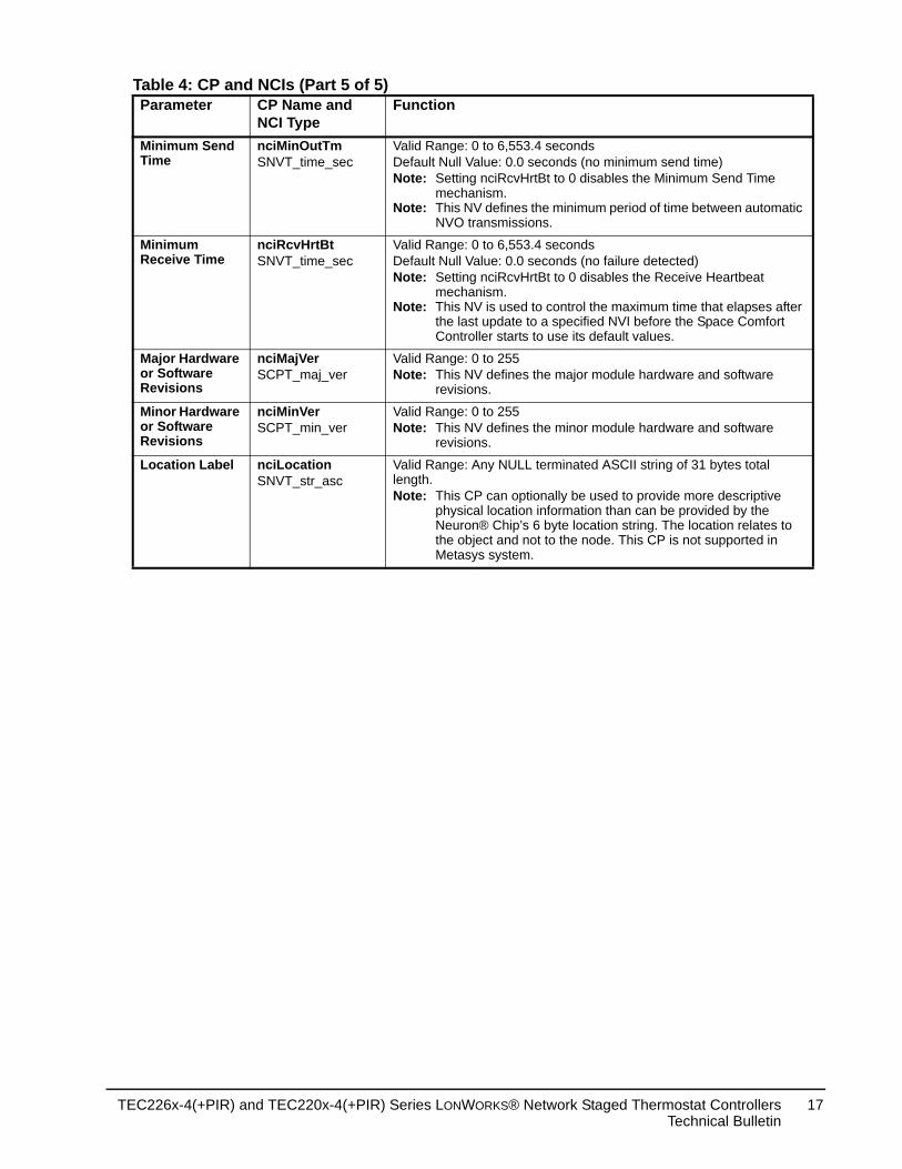
Minimum Send Time
nciMinOutTmSNVT_time_sec
Valid Range: 0 to 6,553.4 secondsDefault Null Value: 0.0 seconds (no minimum send time)Note: Setting nciRcvHrtBt to 0 disables the Minimum Sen
mechanism.Note: This NV defines the minimum period of time betwee
NVO transmissions.
Minimum Receive Time
nciRcvHrtBtSNVT_time_sec
Valid Range: 0 to 6,553.4 secondsDefault Null Value: 0.0 seconds (no failure detected)Note: Setting nciRcvHrtBt to 0 disables the Receive Hear
mechanism.Note: This NV is used to control the maximum time that e
the last update to a specified NVI before the SpaceController starts to use its default values.
Major Hardware or Software Revisions
nciMajVerSCPT_maj_ver
Valid Range: 0 to 255Note: This NV defines the major module hardware and so
revisions.
Minor Hardware or Software Revisions
nciMinVerSCPT_min_ver
Valid Range: 0 to 255Note: This NV defines the minor module hardware and so
revisions.
Location Label nciLocationSNVT_str_asc
Valid Range: Any NULL terminated ASCII string of 31 bytelength.Note: This CP can optionally be used to provide more de
physical location information than can be provided Neuron® Chip’s 6 byte location string. The locationthe object and not to the node. This CP is not suppMetasys system.
Table 4: CP and NCIs (Part 5 of 5)Parameter CP Name and
NCI TypeFunction
TEC226x-4(+PIR) and TEC220x-4(+PIR) Series LONWORKS® Network Staged Thermostat ControllersTechnical Bulletin
17
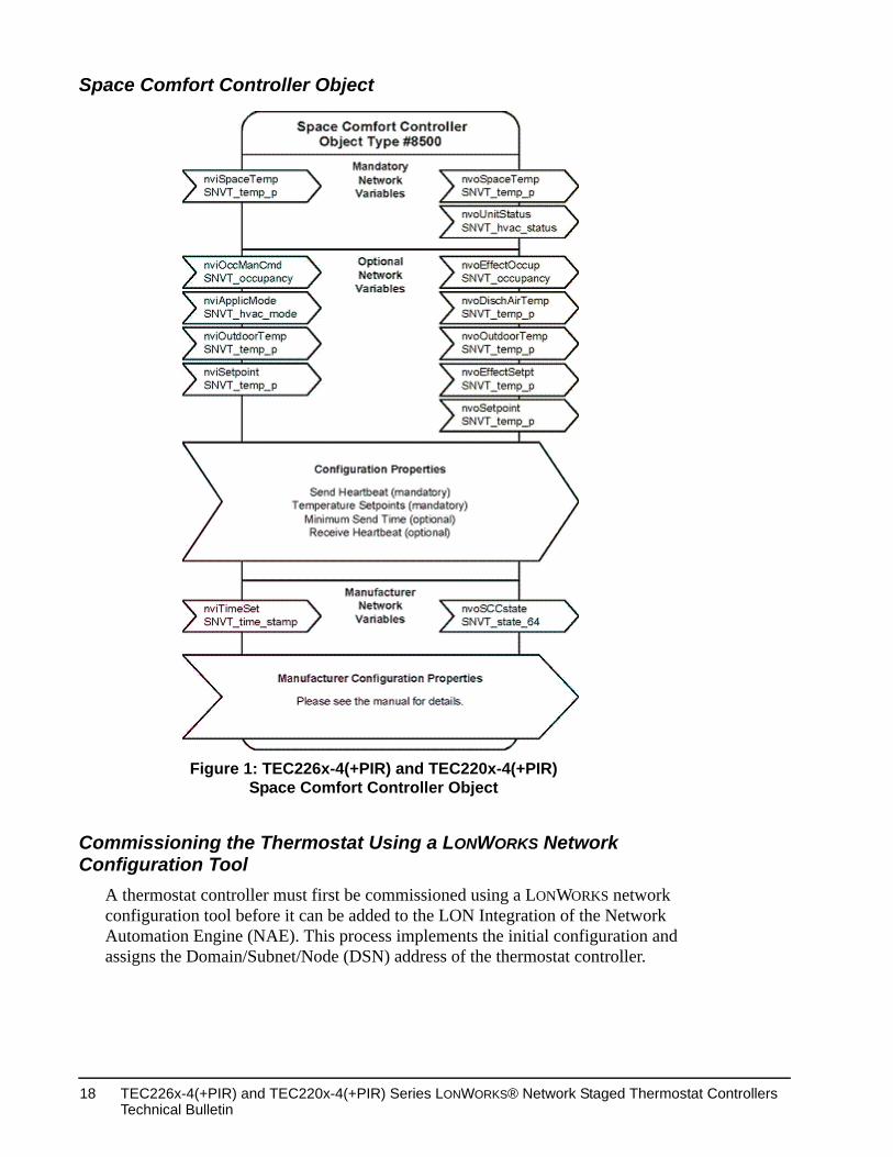
Space Comfort Controller Object
Commissioning the Thermostat Using a LONWORKS Network Configuration Tool
A thermostat controller must first be commissioned using a LONWORKS network configuration tool before it can be added to the LON Integration of the Network Automation Engine (NAE). This process implements the initial configuration and assigns the Domain/Subnet/Node (DSN) address of the thermostat controller.
Figure 1: TEC226x-4(+PIR) and TEC220x-4(+PIR)Space Comfort Controller Object
TEC226x-4(+PIR) and TEC220x-4(+PIR) Series LONWORKS® Network Staged Thermostat Controllers Technical Bulletin
18
Service PinTo broadcast the thermostat’s Neuron ID over the LONWORKS network:
1. Simultaneously press and hold the YES/NO keys until the display illuminates (approximately 5 seconds). The Status LED flashes once every 5 seconds to indicate the thermostat’s Neuron ID is being broadcast on the LONWORKS network.
2. For manual entry, the Neuron ID is also on a label on the Echelon® chip under the thermostat cover.
TEC22xx-4 Configuration Plug-inThe plug-in displays the CPs in a user friendly format for easy configuration. The user can also use LN Browser to display the device CPs for changing the default settings. See the information in the previous sections when making changes to the CPs.
Installing the Plug-in
The TEC22xx-4 Configuration Plug-in must be installed on the same computer that is running the LONWORKS network configuration tool.
To install the plug-in:
1. Open a Web browser.
2. Browse to the following address:http://www.johnsoncontrols.com/publish/us/en/products/building_efficiency/integrated_hvac_systems/hvac/thermostat_product/Network_Resource_File.html
Alternatively, you may browse to the Johnson Controls® Web site athttp://www.johnsoncontrols.com/publish/us/en.htmlThen, use the following path:Building Efficiency > Integrated HVAC Systems > HVAC Control Products > Thermostats > Network Resource Files.
3. Scroll to LONWORKS Network Devices.
4. Click and open the Johnson Controls TEC22xx-4 Plug-in zip file named TEC22xx-4_plug-in.zip.
5. Click and save the plug-in file named TEC22xx-4_plug-in_(Rel_1.1_January_15_2010).zip to your desktop.
6. On your desktop, open the zip file and run the executable file named TEC22xx-4_plug-in.exe.
7. Follow the on-screen prompts and accept all default settings.
Note: The installation adds the resource files to the LNS Resource File Catalog, which is used to correctly display the device data in LN Builder.
TEC226x-4(+PIR) and TEC220x-4(+PIR) Series LONWORKS® Network Staged Thermostat ControllersTechnical Bulletin
19
8. Go to the Registering the Plug-in section.
Registering the Plug-inYou must register the plug-in after installation before you can use it. To register the plug-in:
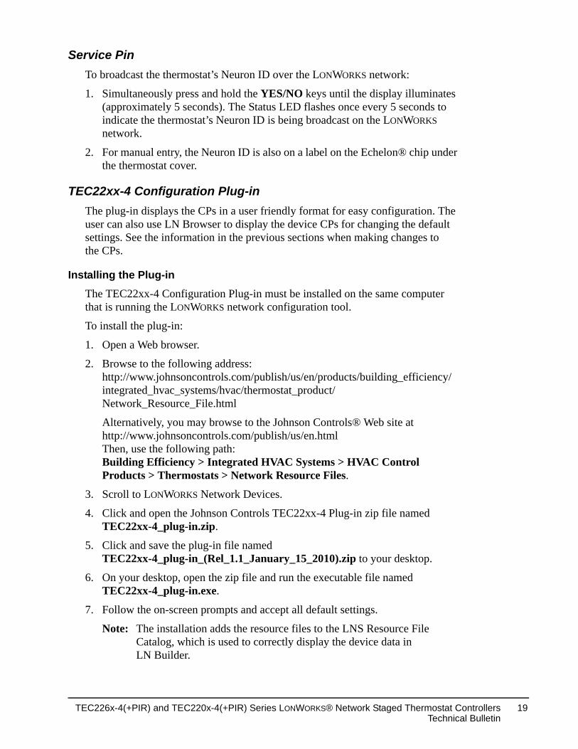
1. Using LN Builder, right-click the LNS database, and then select Plug-Ins (System) > Register (Figure 2). The Register Plug-Ins screen appears.
Note: The plug-in can also be registered at the device level.
Figure 2: Preparing the Plug-in for Registration
TEC226x-4(+PIR) and TEC220x-4(+PIR) Series LONWORKS® Network Staged Thermostat Controllers Technical Bulletin
20
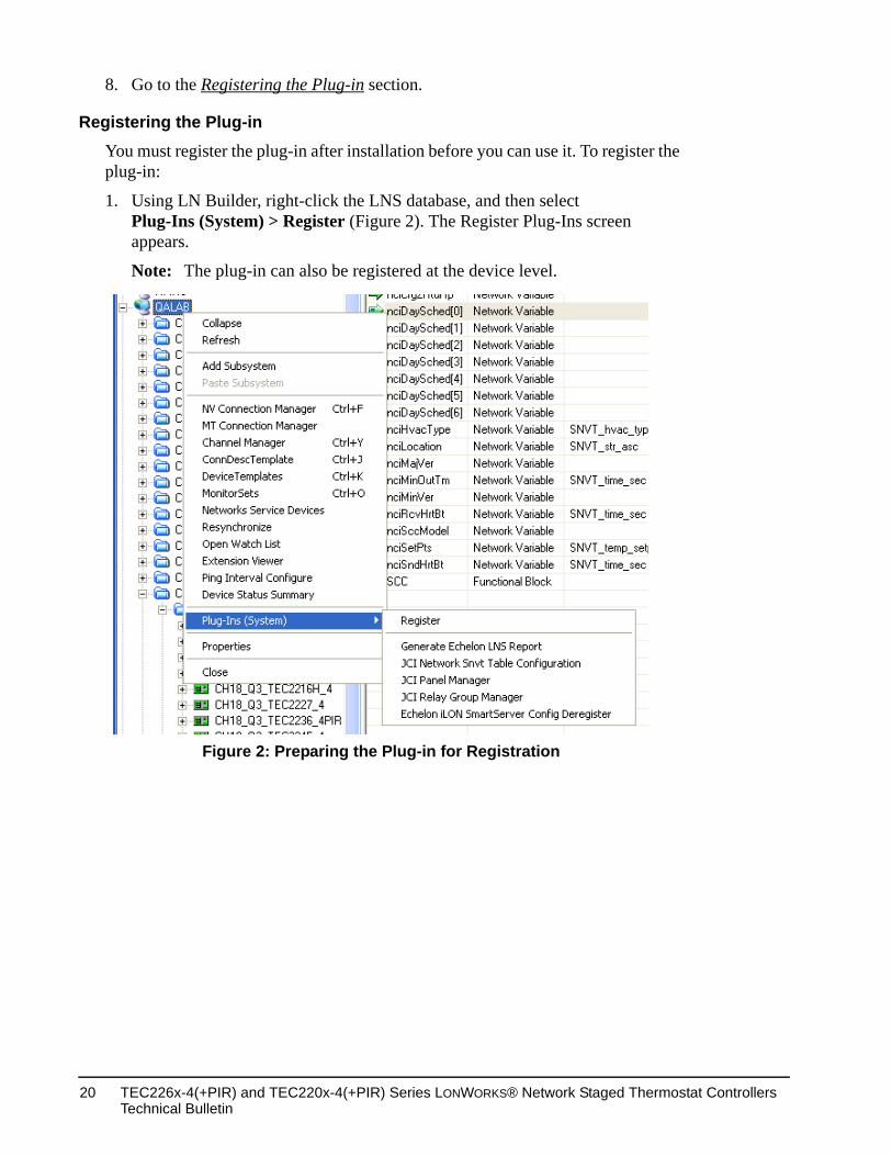
2. Select the Johnson Controls TEC22xx-4 Configure (Version 1.1.0) plug-in from the Not Registered field and click Add (Figure 3). The plug-in appears in the To Register field.
3. Click OK. The plug-in is now registered and the device template is added to the database if it does not already exist.
You are now ready to use the plug-in.
Figure 3: Registering the Plug-in
TEC226x-4(+PIR) and TEC220x-4(+PIR) Series LONWORKS® Network Staged Thermostat ControllersTechnical Bulletin
21
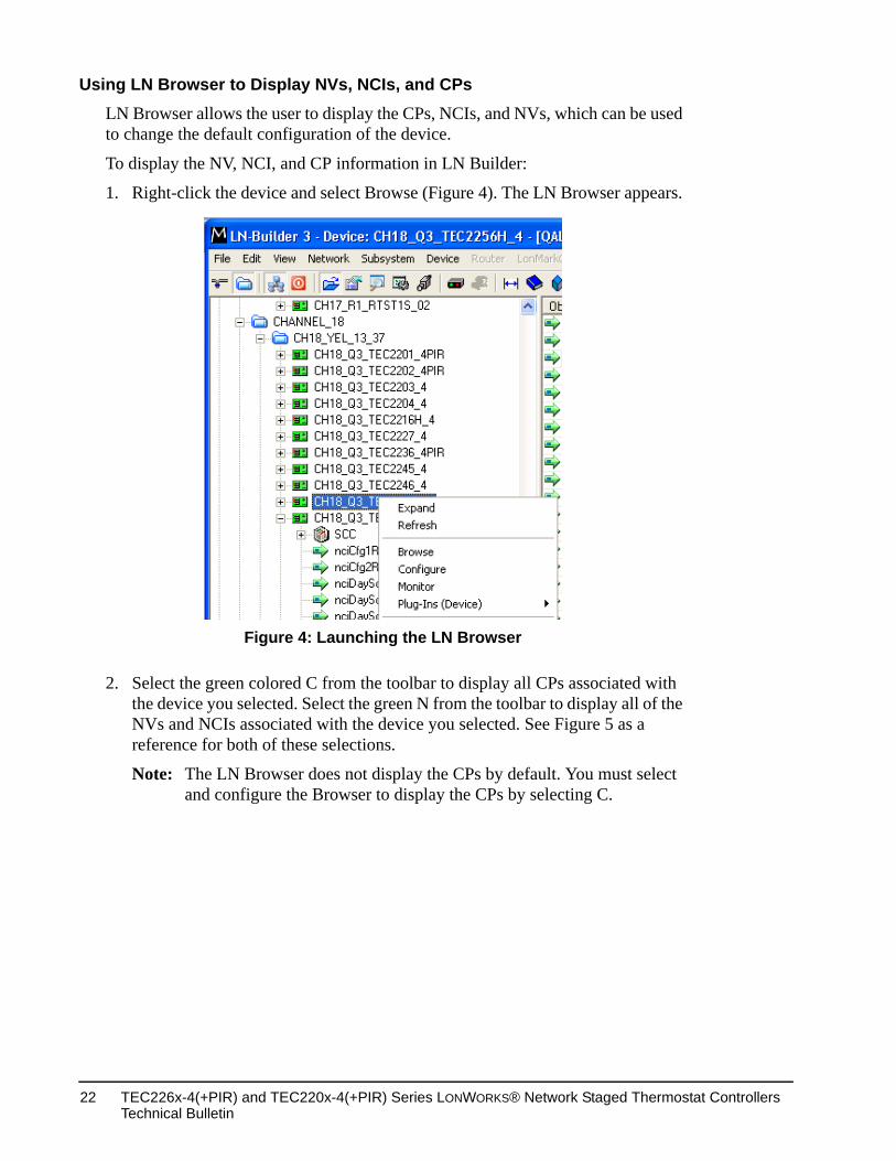
Using LN Browser to Display NVs, NCIs, and CPsLN Browser allows the user to display the CPs, NCIs, and NVs, which can be used to change the default configuration of the device.
To display the NV, NCI, and CP information in LN Builder:
1. Right-click the device and select Browse (Figure 4). The LN Browser appears.
2. Select the green colored C from the toolbar to display all CPs associated with the device you selected. Select the green N from the toolbar to display all of the NVs and NCIs associated with the device you selected. See Figure 5 as a reference for both of these selections.
Note: The LN Browser does not display the CPs by default. You must select and configure the Browser to display the CPs by selecting C.
Figure 4: Launching the LN Browser
TEC226x-4(+PIR) and TEC220x-4(+PIR) Series LONWORKS® Network Staged Thermostat Controllers Technical Bulletin
22
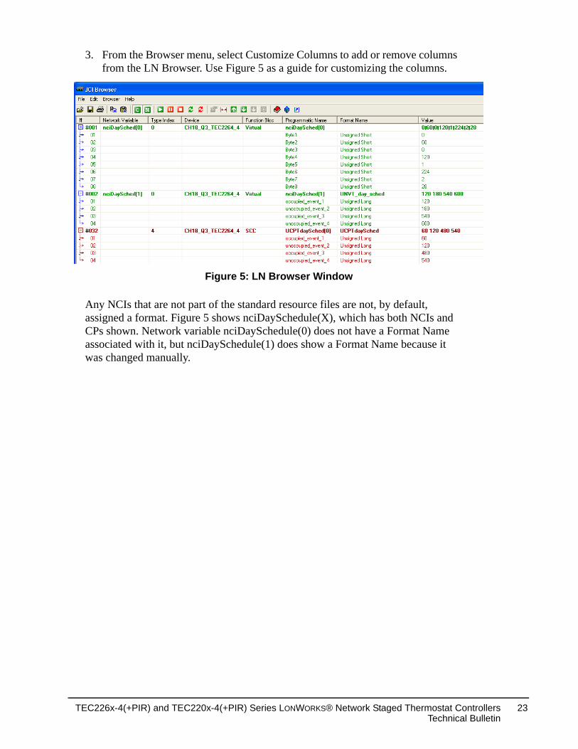
3. From the Browser menu, select Customize Columns to add or remove columns from the LN Browser. Use Figure 5 as a guide for customizing the columns.
Any NCIs that are not part of the standard resource files are not, by default, assigned a format. Figure 5 shows nciDaySchedule(X), which has both NCIs and CPs shown. Network variable nciDaySchedule(0) does not have a Format Name associated with it, but nciDaySchedule(1) does show a Format Name because it was changed manually.
Figure 5: LN Browser Window
TEC226x-4(+PIR) and TEC220x-4(+PIR) Series LONWORKS® Network Staged Thermostat ControllersTechnical Bulletin
23
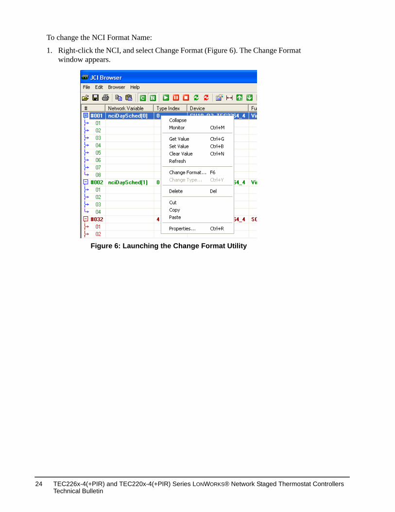
To change the NCI Format Name:
1. Right-click the NCI, and select Change Format (Figure 6). The Change Format window appears.
Figure 6: Launching the Change Format Utility
TEC226x-4(+PIR) and TEC220x-4(+PIR) Series LONWORKS® Network Staged Thermostat Controllers Technical Bulletin
24
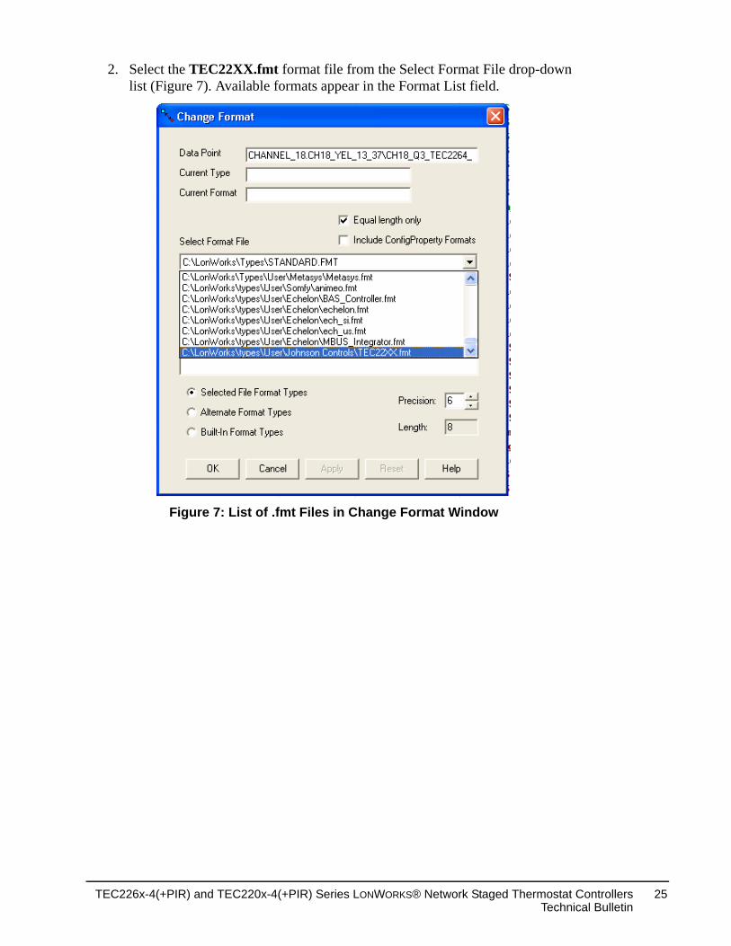
2. Select the TEC22XX.fmt format file from the Select Format File drop-down list (Figure 7). Available formats appear in the Format List field.
Figure 7: List of .fmt Files in Change Format Window
TEC226x-4(+PIR) and TEC220x-4(+PIR) Series LONWORKS® Network Staged Thermostat ControllersTechnical Bulletin
25
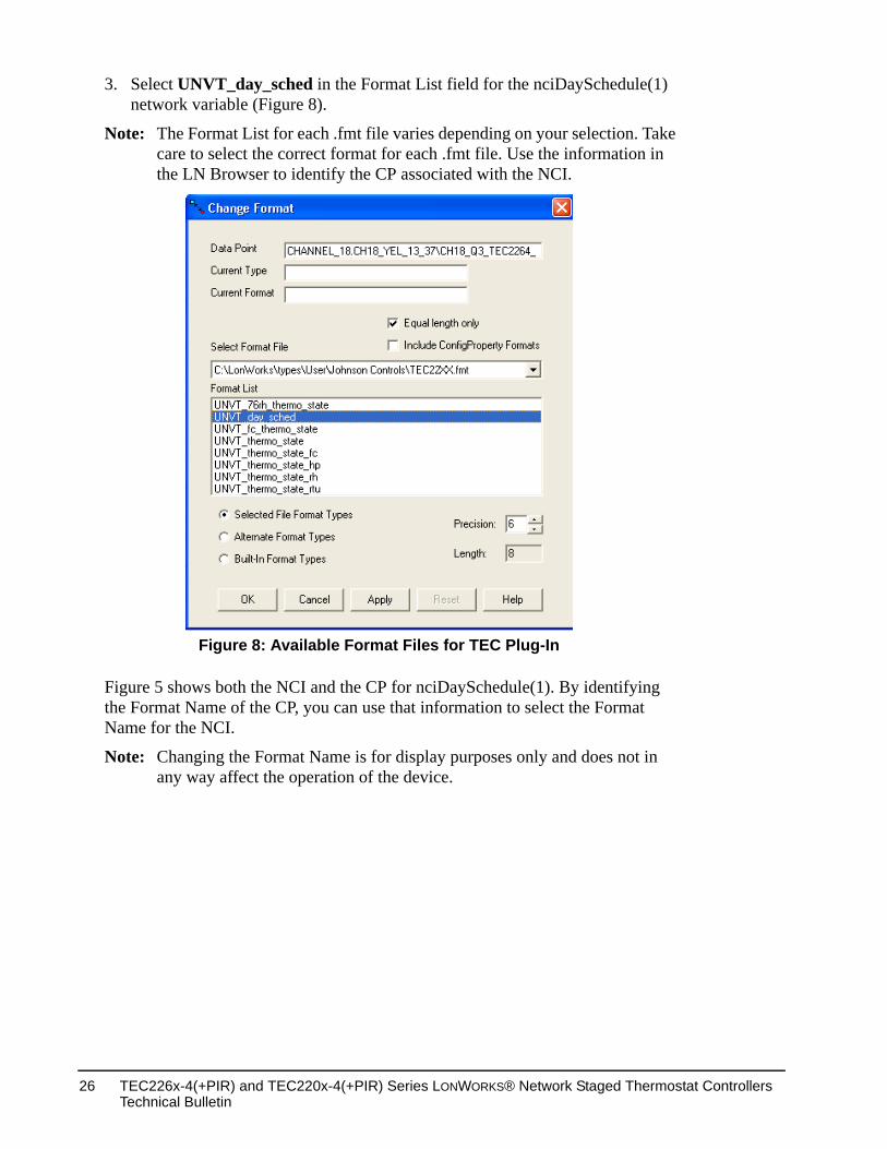
3. Select UNVT_day_sched in the Format List field for the nciDaySchedule(1) network variable (Figure 8).
Note: The Format List for each .fmt file varies depending on your selection. Take care to select the correct format for each .fmt file. Use the information in the LN Browser to identify the CP associated with the NCI.
Figure 5 shows both the NCI and the CP for nciDaySchedule(1). By identifying the Format Name of the CP, you can use that information to select the Format Name for the NCI.
Note: Changing the Format Name is for display purposes only and does not in any way affect the operation of the device.
Figure 8: Available Format Files for TEC Plug-In
TEC226x-4(+PIR) and TEC220x-4(+PIR) Series LONWORKS® Network Staged Thermostat Controllers Technical Bulletin
26
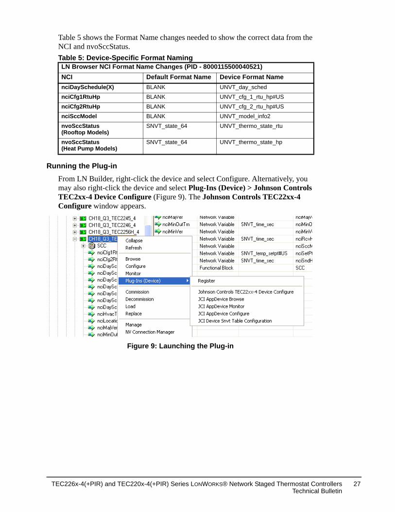
Table 5 shows the Format Name changes needed to show the correct data from the NCI and nvoSccStatus.
Running the Plug-in
From LN Builder, right-click the device and select Configure. Alternatively, you may also right-click the device and select Plug-Ins (Device) > Johnson Controls TEC2xx-4 Device Configure (Figure 9). The Johnson Controls TEC22xx-4 Configure window appears.
Table 5: Device-Specific Format NamingLN Browser NCI Format Name Changes (PID - 8000115500040521)NCI Default Format Name Device Format NamenciDaySchedule(X) BLANK UNVT_day_sched
nciCfg1RtuHp BLANK UNVT_cfg_1_rtu_hp#US
nciCfg2RtuHp BLANK UNVT_cfg_2_rtu_hp#US
nciSccModel BLANK UNVT_model_info2
nvoSccStatus (Rooftop Models)
SNVT_state_64 UNVT_thermo_state_rtu
nvoSccStatus (Heat Pump Models)
SNVT_state_64 UNVT_thermo_state_hp
Figure 9: Launching the Plug-in
TEC226x-4(+PIR) and TEC220x-4(+PIR) Series LONWORKS® Network Staged Thermostat ControllersTechnical Bulletin
27
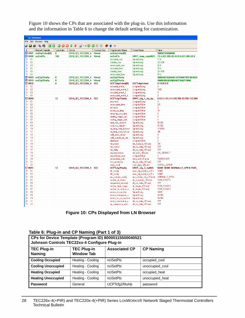
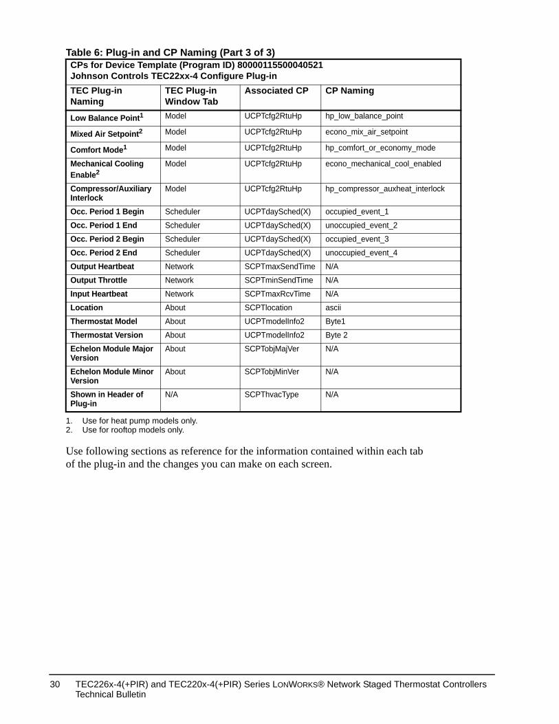
Figure 10 shows the CPs that are associated with the plug-in. Use this information and the information in Table 6 to change the default setting for customization.
Table 6: Plug-in and CP Naming (Part 1 of 3)CPs for Device Template (Program ID) 80000115500040521 Johnson Controls TEC22xx-4 Configure Plug-inTEC Plug-in Naming
TEC Plug-in Window Tab
Associated CP CP Naming
Cooling Occupied Heating - Cooling nciSetPts occupied_cool
Cooling Unoccupied Heating - Cooling nciSetPts unoccupied_cool
Heating Occupied Heating - Cooling nciSetPts occupied_heat
Heating Unoccupied Heating - Cooling nciSetPts unoccupied_heat
Password General UCPTcfg1RtuHp password
Figure 10: CPs Displayed from LN Browser
TEC226x-4(+PIR) and TEC220x-4(+PIR) Series LONWORKS® Network Staged Thermostat Controllers Technical Bulletin
28
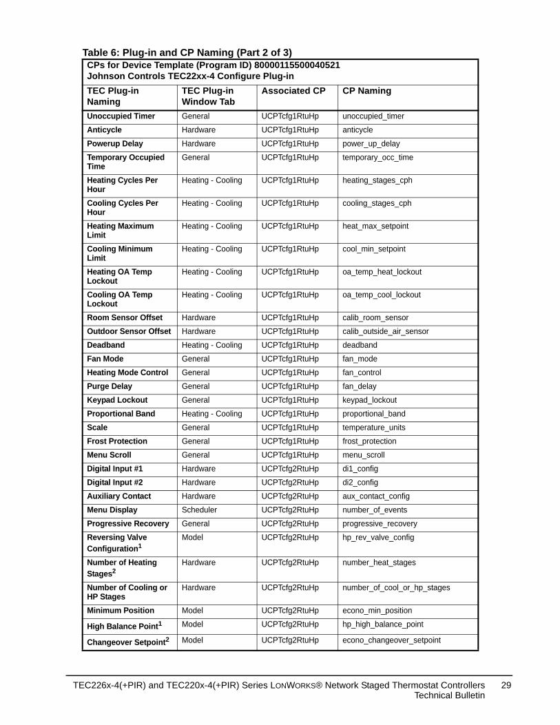
Unoccupied Timer General UCPTcfg1RtuHp unoccupied_timer
Anticycle Hardware UCPTcfg1RtuHp anticycle
Powerup Delay Hardware UCPTcfg1RtuHp power_up_delay
Temporary Occupied Time
General UCPTcfg1RtuHp temporary_occ_time
Heating Cycles Per Hour
Heating - Cooling UCPTcfg1RtuHp heating_stages_cph
Cooling Cycles Per Hour
Heating - Cooling UCPTcfg1RtuHp cooling_stages_cph
Heating Maximum Limit
Heating - Cooling UCPTcfg1RtuHp heat_max_setpoint
Cooling Minimum Limit
Heating - Cooling UCPTcfg1RtuHp cool_min_setpoint
Heating OA Temp Lockout
Heating - Cooling UCPTcfg1RtuHp oa_temp_heat_lockout
Cooling OA Temp Lockout
Heating - Cooling UCPTcfg1RtuHp oa_temp_cool_lockout
Room Sensor Offset Hardware UCPTcfg1RtuHp calib_room_sensor
Outdoor Sensor Offset Hardware UCPTcfg1RtuHp calib_outside_air_sensor
Deadband Heating - Cooling UCPTcfg1RtuHp deadband
Fan Mode General UCPTcfg1RtuHp fan_mode
Heating Mode Control General UCPTcfg1RtuHp fan_control
Purge Delay General UCPTcfg1RtuHp fan_delay
Keypad Lockout General UCPTcfg1RtuHp keypad_lockout
Proportional Band Heating - Cooling UCPTcfg1RtuHp proportional_band
Scale General UCPTcfg1RtuHp temperature_units
Frost Protection General UCPTcfg1RtuHp frost_protection
Menu Scroll General UCPTcfg1RtuHp menu_scroll
Digital Input #1 Hardware UCPTcfg2RtuHp di1_config
Digital Input #2 Hardware UCPTcfg2RtuHp di2_config
Auxiliary Contact Hardware UCPTcfg2RtuHp aux_contact_config
Menu Display Scheduler UCPTcfg2RtuHp number_of_events
Progressive Recovery General UCPTcfg2RtuHp progressive_recovery
Reversing Valve Configuration1
Model UCPTcfg2RtuHp hp_rev_valve_config
Number of Heating Stages2
Hardware UCPTcfg2RtuHp number_heat_stages
Number of Cooling or HP Stages
Hardware UCPTcfg2RtuHp number_of_cool_or_hp_stages
Minimum Position Model UCPTcfg2RtuHp econo_min_position
High Balance Point1 Model UCPTcfg2RtuHp hp_high_balance_point
Changeover Setpoint2 Model UCPTcfg2RtuHp econo_changeover_setpoint
Table 6: Plug-in and CP Naming (Part 2 of 3)CPs for Device Template (Program ID) 80000115500040521 Johnson Controls TEC22xx-4 Configure Plug-inTEC Plug-in Naming
TEC Plug-in Window Tab
Associated CP CP Naming
TEC226x-4(+PIR) and TEC220x-4(+PIR) Series LONWORKS® Network Staged Thermostat ControllersTechnical Bulletin
29
d
ck
Use following sections as reference for the information contained within each tab of the plug-in and the changes you can make on each screen.
Low Balance Point1 Model UCPTcfg2RtuHp hp_low_balance_point
Mixed Air Setpoint2 Model UCPTcfg2RtuHp econo_mix_air_setpoint
Comfort Mode1 Model UCPTcfg2RtuHp hp_comfort_or_economy_mode
Mechanical Cooling Enable2
Model UCPTcfg2RtuHp econo_mechanical_cool_enable
Compressor/Auxiliary Interlock
Model UCPTcfg2RtuHp hp_compressor_auxheat_interlo
Occ. Period 1 Begin Scheduler UCPTdaySched(X) occupied_event_1
Occ. Period 1 End Scheduler UCPTdaySched(X) unoccupied_event_2
Occ. Period 2 Begin Scheduler UCPTdaySched(X) occupied_event_3
Occ. Period 2 End Scheduler UCPTdaySched(X) unoccupied_event_4
Output Heartbeat Network SCPTmaxSendTime N/A
Output Throttle Network SCPTminSendTime N/A
Input Heartbeat Network SCPTmaxRcvTime N/A
Location About SCPTlocation ascii
Thermostat Model About UCPTmodelInfo2 Byte1
Thermostat Version About UCPTmodelInfo2 Byte 2
Echelon Module Major Version
About SCPTobjMajVer N/A
Echelon Module Minor Version
About SCPTobjMinVer N/A
Shown in Header of Plug-in
N/A SCPThvacType N/A
1. Use for heat pump models only.2. Use for rooftop models only.
Table 6: Plug-in and CP Naming (Part 3 of 3)CPs for Device Template (Program ID) 80000115500040521 Johnson Controls TEC22xx-4 Configure Plug-inTEC Plug-in Naming
TEC Plug-in Window Tab
Associated CP CP Naming
TEC226x-4(+PIR) and TEC220x-4(+PIR) Series LONWORKS® Network Staged Thermostat Controllers Technical Bulletin
30
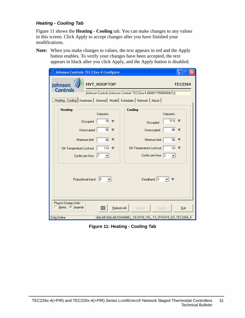
Heating - Cooling Tab
Figure 11 shows the Heating - Cooling tab. You can make changes to any values in this screen. Click Apply to accept changes after you have finished your modifications.
Note: When you make changes to values, the text appears in red and the Apply button enables. To verify your changes have been accepted, the text appears in black after you click Apply, and the Apply button is disabled.
Figure 11: Heating - Cooling Tab
TEC226x-4(+PIR) and TEC220x-4(+PIR) Series LONWORKS® Network Staged Thermostat ControllersTechnical Bulletin
31
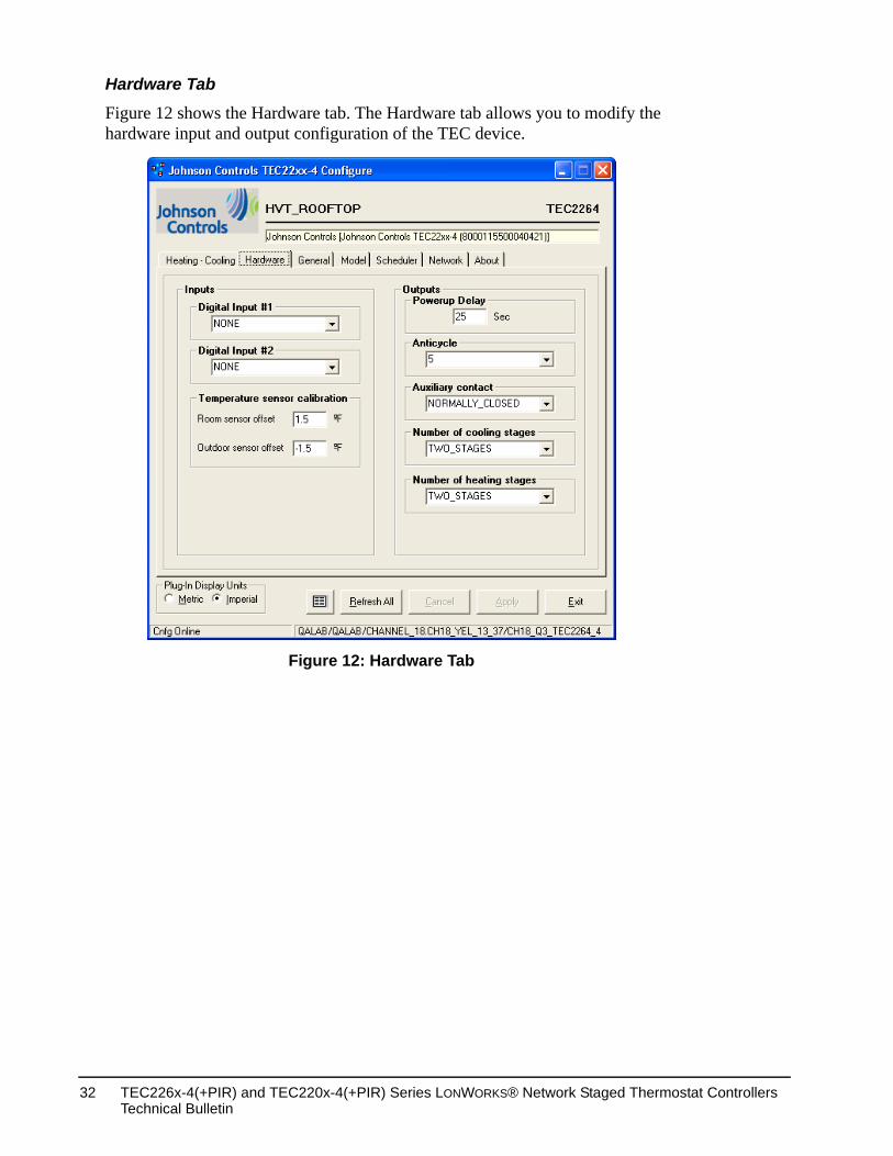
Hardware Tab
Figure 12 shows the Hardware tab. The Hardware tab allows you to modify the hardware input and output configuration of the TEC device.
Figure 12: Hardware Tab
TEC226x-4(+PIR) and TEC220x-4(+PIR) Series LONWORKS® Network Staged Thermostat Controllers Technical Bulletin
32
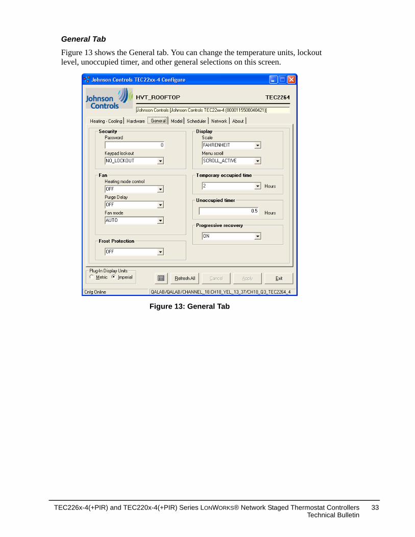
General Tab
Figure 13 shows the General tab. You can change the temperature units, lockout level, unoccupied timer, and other general selections on this screen.
Figure 13: General Tab
TEC226x-4(+PIR) and TEC220x-4(+PIR) Series LONWORKS® Network Staged Thermostat ControllersTechnical Bulletin
33
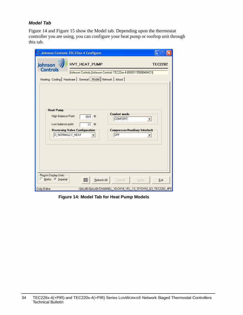
Model Tab
Figure 14 and Figure 15 show the Model tab. Depending upon the thermostat controller you are using, you can configure your heat pump or rooftop unit through this tab.
Figure 14: Model Tab for Heat Pump Models
TEC226x-4(+PIR) and TEC220x-4(+PIR) Series LONWORKS® Network Staged Thermostat Controllers Technical Bulletin
34
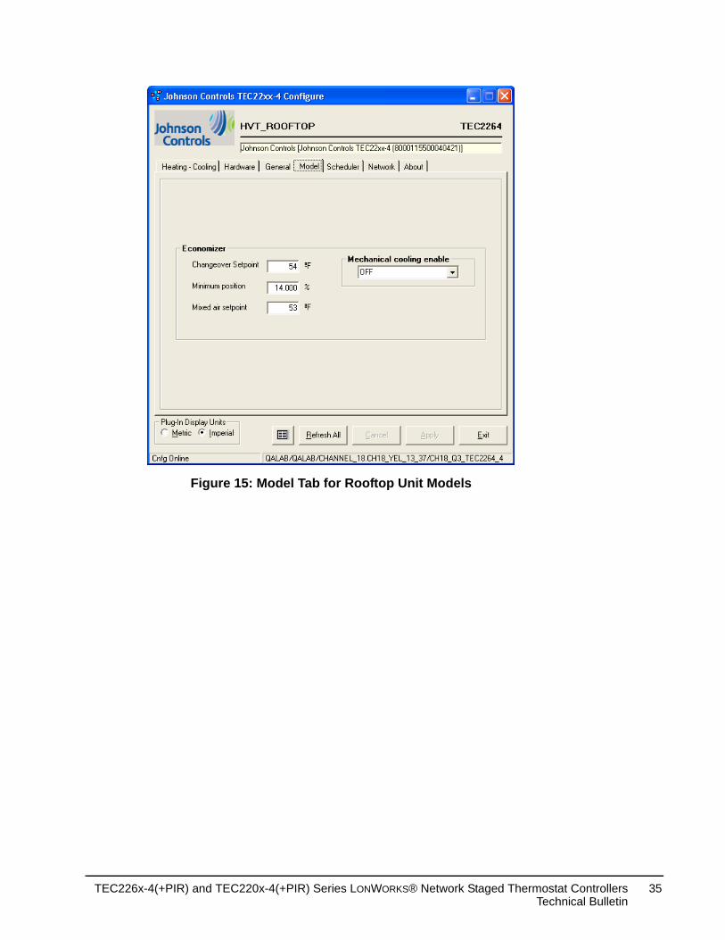
Figure 15: Model Tab for Rooftop Unit Models
TEC226x-4(+PIR) and TEC220x-4(+PIR) Series LONWORKS® Network Staged Thermostat ControllersTechnical Bulletin
35
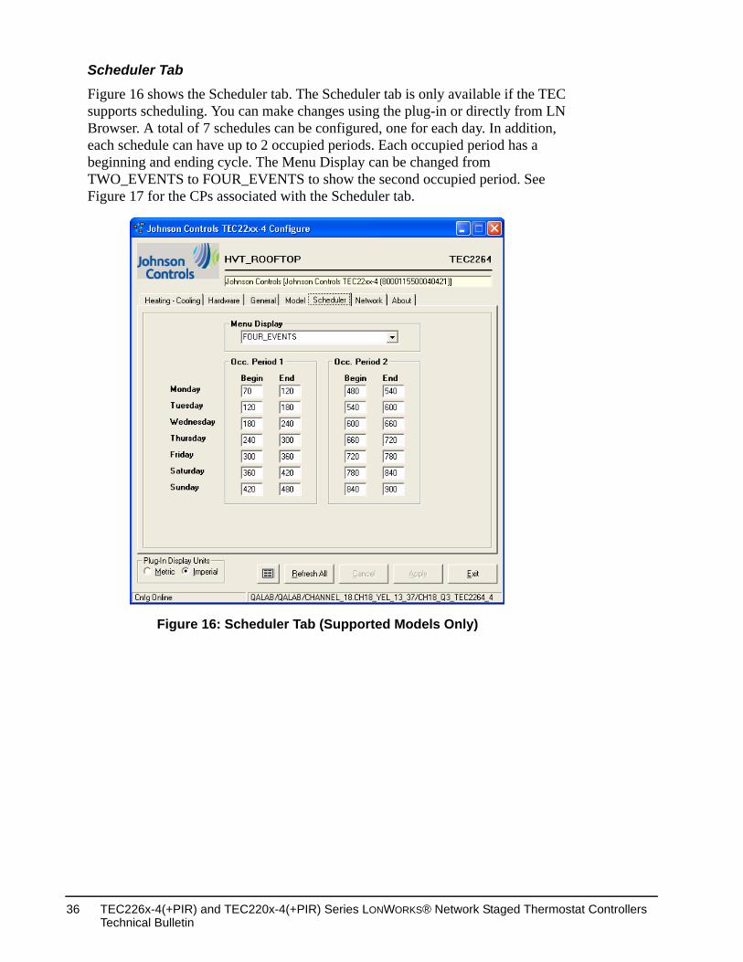
Scheduler Tab
Figure 16 shows the Scheduler tab. The Scheduler tab is only available if the TEC supports scheduling. You can make changes using the plug-in or directly from LN Browser. A total of 7 schedules can be configured, one for each day. In addition, each schedule can have up to 2 occupied periods. Each occupied period has a beginning and ending cycle. The Menu Display can be changed from TWO_EVENTS to FOUR_EVENTS to show the second occupied period. See Figure 17 for the CPs associated with the Scheduler tab.
Figure 16: Scheduler Tab (Supported Models Only)
TEC226x-4(+PIR) and TEC220x-4(+PIR) Series LONWORKS® Network Staged Thermostat Controllers Technical Bulletin
36
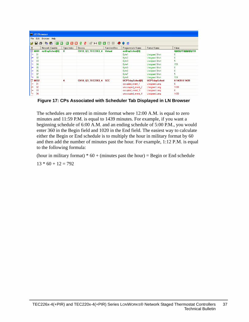
The schedules are entered in minute format where 12:00 A.M. is equal to zero minutes and 11:59 P.M. is equal to 1439 minutes. For example, if you want a beginning schedule of 6:00 A.M. and an ending schedule of 5:00 P.M., you would enter 360 in the Begin field and 1020 in the End field. The easiest way to calculate either the Begin or End schedule is to multiply the hour in military format by 60 and then add the number of minutes past the hour. For example, 1:12 P.M. is equal to the following formula:
(hour in military format) * 60 + (minutes past the hour) = Begin or End schedule
13 * 60 + 12 = 792
Figure 17: CPs Associated with Scheduler Tab Displayed in LN Browser
TEC226x-4(+PIR) and TEC220x-4(+PIR) Series LONWORKS® Network Staged Thermostat ControllersTechnical Bulletin
37
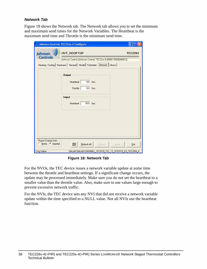
Network Tab
Figure 18 shows the Network tab. The Network tab allows you to set the minimum and maximum send times for the Network Variables. The Heartbeat is the maximum send time and Throttle is the minimum send time.
For the NVOs, the TEC device issues a network variable update at some time between the throttle and heartbeat settings. If a significant change occurs, the update may be processed immediately. Make sure you do not set the heartbeat to a smaller value than the throttle value. Also, make sure to use values large enough to prevent excessive network traffic.
For the NVIs, the TEC device sets any NVI that did not receive a network variable update within the time specified to a NULL value. Not all NVIs use the heartbeat function.
Figure 18: Network Tab
TEC226x-4(+PIR) and TEC220x-4(+PIR) Series LONWORKS® Network Staged Thermostat Controllers Technical Bulletin
38
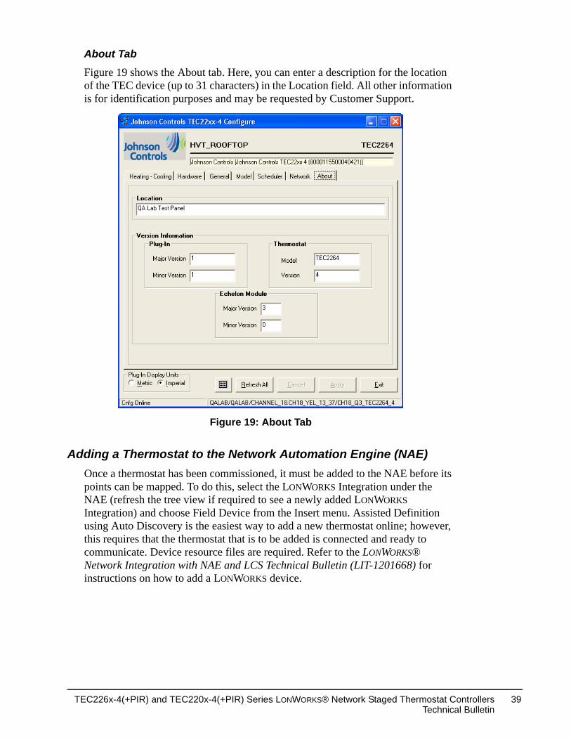
About Tab
Figure 19 shows the About tab. Here, you can enter a description for the location of the TEC device (up to 31 characters) in the Location field. All other information is for identification purposes and may be requested by Customer Support.
Adding a Thermostat to the Network Automation Engine (NAE)Once a thermostat has been commissioned, it must be added to the NAE before its points can be mapped. To do this, select the LONWORKS Integration under the NAE (refresh the tree view if required to see a newly added LONWORKS Integration) and choose Field Device from the Insert menu. Assisted Definition using Auto Discovery is the easiest way to add a new thermostat online; however, this requires that the thermostat that is to be added is connected and ready to communicate. Device resource files are required. Refer to the LONWORKS® Network Integration with NAE and LCS Technical Bulletin (LIT-1201668) for instructions on how to add a LONWORKS device.
Figure 19: About Tab
TEC226x-4(+PIR) and TEC220x-4(+PIR) Series LONWORKS® Network Staged Thermostat ControllersTechnical Bulletin
39
LONWORKS Thermostat Controller Mapping
PreparationBefore mapping a TEC226x-4(+PIR) or TEC220x-4(+PIR) Thermostat Controller into an NAE:
1. Decide which point objects within the thermostat need to be mapped. Only map the point objects that need to be viewed on a regular basis, because excessive mapping lowers system performance. Suggested point objects for mapping include: Room Temp, System Mode, Fan Status, Occupied Heat Setpoint, Occupied Cool Setpoint, Unoccupied Heat Setpoint, and Unoccupied Cool Setpoint. In addition, alarm points may be mapped if they are used, and other point objects may be mapped if required. Use the Engineering view to examine infrequently used point objects.
2. Verify that a LONWORKS Integration is defined in the NAE. The commissioned thermostat is mapped as a LONWORKS device under a LONWORKS Integration. Refer to the LONWORKS® Network Integration with NAE and LCS Technical Bulletin (LIT-1201668) for instructions on how to define a LONWORKS network integration.
At this point, the thermostat and the required point objects inside the thermostat can be mapped.
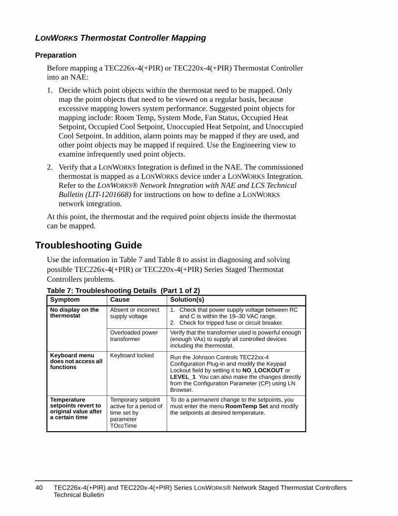
Troubleshooting GuideUse the information in Table 7 and Table 8 to assist in diagnosing and solving possible TEC226x-4(+PIR) or TEC220x-4(+PIR) Series Staged Thermostat Controllers problems. Table 7: Troubleshooting Details (Part 1 of 2)Symptom Cause Solution(s)No display on the thermostat
Absent or incorrect supply voltage
1. Check that power supply voltage between RC and C is within the 19–30 VAC range.
2. Check for tripped fuse or circuit breaker.
Overloaded power transformer
Verify that the transformer used is powerful enough (enough VAs) to supply all controlled devices including the thermostat.
Keyboard menu does not access all functions
Keyboard locked Run the Johnson Controls TEC22xx-4 Configuration Plug-in and modify the Keypad Lockout field by setting it to NO_LOCKOUT or LEVEL_1. You can also make the changes directly from the Configuration Parameter (CP) using LN Browser.
Temperature setpoints revert to original value after a certain time
Temporary setpoint active for a period of time set by parameter TOccTime
To do a permanent change to the setpoints, you must enter the menu RoomTemp Set and modify the setpoints at desired temperature.
TEC226x-4(+PIR) and TEC220x-4(+PIR) Series LONWORKS® Network Staged Thermostat Controllers Technical Bulletin
40
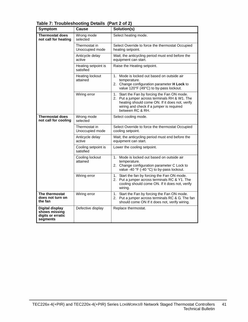
Thermostat does not call for heating
Wrong mode selected
Select heating mode.
Thermostat in Unoccupied mode
Select Override to force the thermostat Occupied heating setpoint.
Anticycle delay active
Wait; the anticycling period must end before the equipment can start.
Heating setpoint is satisfied
Raise the Heating setpoint.
Heating lockout attained
1. Mode is locked out based on outside air temperature.
2. Change configuration parameter H Lock to value 120°F (49°C) to by-pass lockout.
Wiring error 1. Start the Fan by forcing the Fan ON mode.2. Put a jumper across terminals RH & W1. The
heating should come ON. If it does not, verify wiring and check if a jumper is required between RC & RH.
Thermostat does not call for cooling
Wrong mode selected
Select cooling mode.
Thermostat in Unoccupied mode
Select Override to force the thermostat Occupied cooling setpoint.
Anticycle delay active
Wait; the anticycling period must end before the equipment can start.
Cooling setpoint is satisfied
Lower the cooling setpoint.
Cooling lockout attained
1. Mode is locked out based on outside air temperature.
2. Change configuration parameter C Lock to value -40 °F (-40 °C) to by-pass lockout.
Wiring error 1. Start the fan by forcing the Fan ON mode.2. Put a jumper across terminals RC & Y1. The
cooling should come ON. If it does not, verify wiring.
The thermostat does not turn on the fan
Wiring error 1. Start the Fan by forcing the Fan ON mode.2. Put a jumper across terminals RC & G. The fan
should come ON If it does not, verify wiring.
Digital display shows missing digits or erratic segments
Defective display Replace thermostat.
Table 7: Troubleshooting Details (Part 2 of 2)Symptom Cause Solution(s)
TEC226x-4(+PIR) and TEC220x-4(+PIR) Series LONWORKS® Network Staged Thermostat ControllersTechnical Bulletin
41
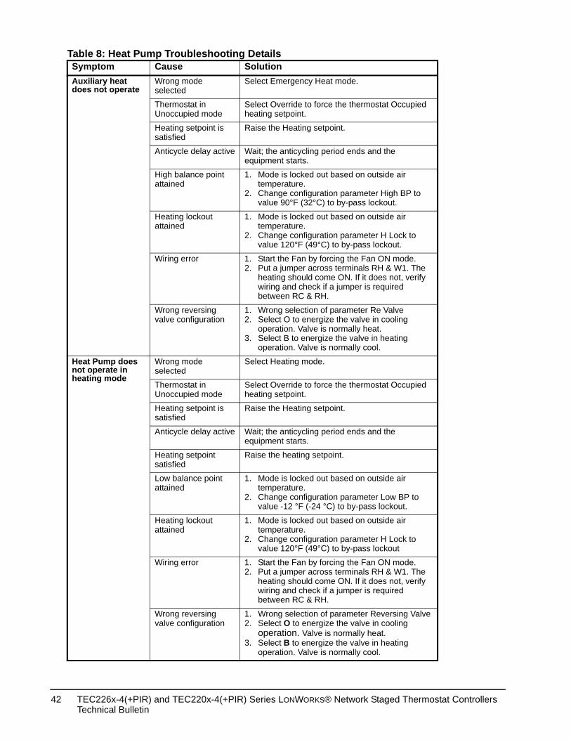
Table 8: Heat Pump Troubleshooting Details Symptom Cause SolutionAuxiliary heat does not operate
Wrong mode selected
Select Emergency Heat mode.
Thermostat in Unoccupied mode
Select Override to force the thermostat Occupied heating setpoint.
Heating setpoint is satisfied
Raise the Heating setpoint.
Anticycle delay active Wait; the anticycling period ends and the equipment starts.
High balance point attained
1. Mode is locked out based on outside air temperature.
2. Change configuration parameter High BP to value 90°F (32°C) to by-pass lockout.
Heating lockout attained
1. Mode is locked out based on outside air temperature.
2. Change configuration parameter H Lock to value 120°F (49°C) to by-pass lockout.
Wiring error 1. Start the Fan by forcing the Fan ON mode.2. Put a jumper across terminals RH & W1. The
heating should come ON. If it does not, verify wiring and check if a jumper is required between RC & RH.
Wrong reversing valve configuration
1. Wrong selection of parameter Re Valve2. Select O to energize the valve in cooling
operation. Valve is normally heat.3. Select B to energize the valve in heating
operation. Valve is normally cool.
Heat Pump does not operate in heating mode
Wrong mode selected
Select Heating mode.
Thermostat in Unoccupied mode
Select Override to force the thermostat Occupied heating setpoint.
Heating setpoint is satisfied
Raise the Heating setpoint.
Anticycle delay active Wait; the anticycling period ends and the equipment starts.
Heating setpoint satisfied
Raise the heating setpoint.
Low balance point attained
1. Mode is locked out based on outside air temperature.
2. Change configuration parameter Low BP to value -12 °F (-24 °C) to by-pass lockout.
Heating lockout attained
1. Mode is locked out based on outside air temperature.
2. Change configuration parameter H Lock to value 120°F (49°C) to by-pass lockout
Wiring error 1. Start the Fan by forcing the Fan ON mode.2. Put a jumper across terminals RH & W1. The
heating should come ON. If it does not, verify wiring and check if a jumper is required between RC & RH.
Wrong reversing valve configuration
1. Wrong selection of parameter Reversing Valve2. Select O to energize the valve in cooling
operation. Valve is normally heat.3. Select B to energize the valve in heating
operation. Valve is normally cool.
TEC226x-4(+PIR) and TEC220x-4(+PIR) Series LONWORKS® Network Staged Thermostat Controllers Technical Bulletin
42
al, Class 2 or
2 or SELV
ative Temperature
WG (1.0 mm
peater; 6,250 ft
g Equipment
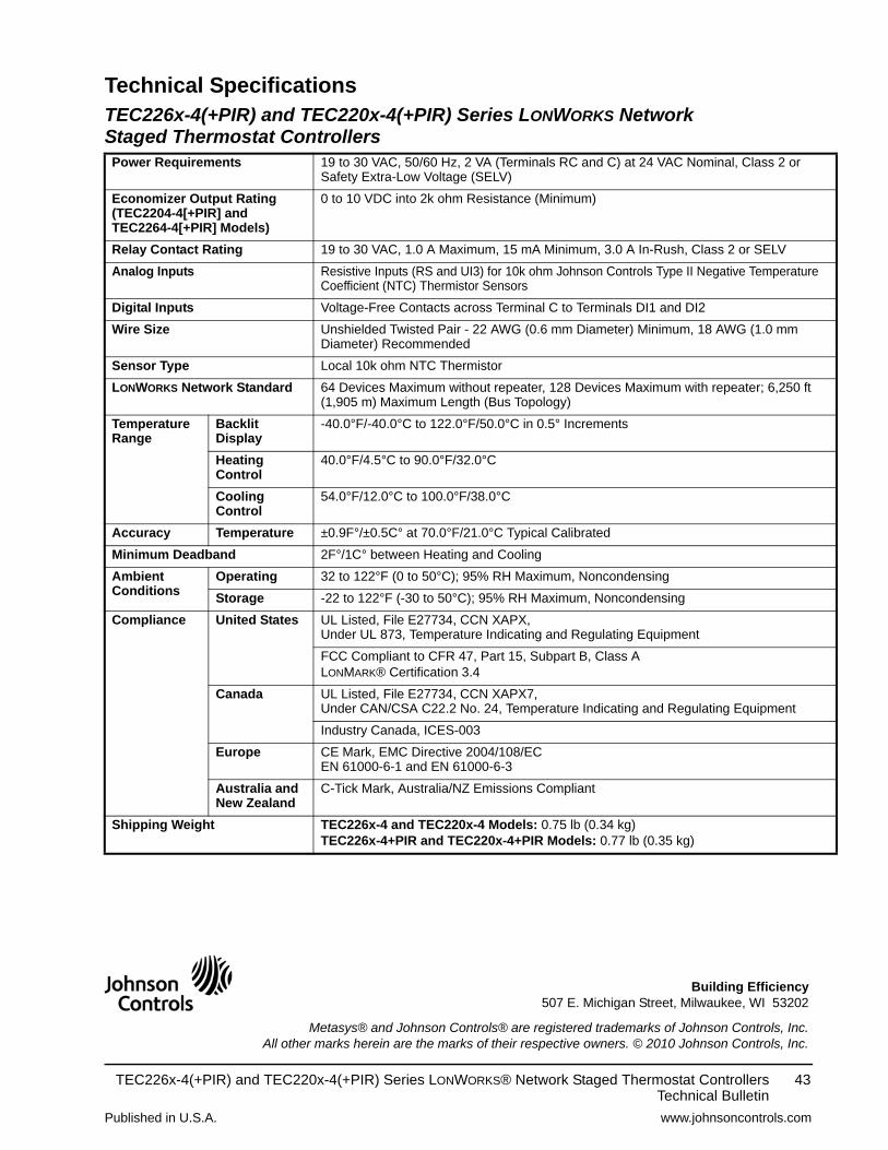
Technical Specifications TEC226x-4(+PIR) and TEC220x-4(+PIR) Series LONWORKS NetworkStaged Thermostat ControllersPower Requirements 19 to 30 VAC, 50/60 Hz, 2 VA (Terminals RC and C) at 24 VAC Nomin
Safety Extra-Low Voltage (SELV)
Economizer Output Rating (TEC2204-4[+PIR] and TEC2264-4[+PIR] Models)
0 to 10 VDC into 2k ohm Resistance (Minimum)
Relay Contact Rating 19 to 30 VAC, 1.0 A Maximum, 15 mA Minimum, 3.0 A In-Rush, Class
Analog Inputs Resistive Inputs (RS and UI3) for 10k ohm Johnson Controls Type II NegCoefficient (NTC) Thermistor Sensors
Digital Inputs Voltage-Free Contacts across Terminal C to Terminals DI1 and DI2
Wire Size Unshielded Twisted Pair - 22 AWG (0.6 mm Diameter) Minimum, 18 ADiameter) Recommended
Sensor Type Local 10k ohm NTC Thermistor
LONWORKS Network Standard 64 Devices Maximum without repeater, 128 Devices Maximum with re(1,905 m) Maximum Length (Bus Topology)
Temperature Range
Backlit Display
-40.0°F/-40.0°C to 122.0°F/50.0°C in 0.5° Increments
Heating Control
40.0°F/4.5°C to 90.0°F/32.0°C
Cooling Control
54.0°F/12.0°C to 100.0°F/38.0°C
Accuracy Temperature ±0.9F°/±0.5C° at 70.0°F/21.0°C Typical Calibrated
Minimum Deadband 2F°/1C° between Heating and Cooling
Ambient Conditions
Operating 32 to 122°F (0 to 50°C); 95% RH Maximum, Noncondensing
Storage -22 to 122°F (-30 to 50°C); 95% RH Maximum, Noncondensing
Compliance United States UL Listed, File E27734, CCN XAPX, Under UL 873, Temperature Indicating and Regulating Equipment
FCC Compliant to CFR 47, Part 15, Subpart B, Class ALONMARK® Certification 3.4
Canada UL Listed, File E27734, CCN XAPX7,Under CAN/CSA C22.2 No. 24, Temperature Indicating and Regulatin
Industry Canada, ICES-003
Europe CE Mark, EMC Directive 2004/108/ECEN 61000-6-1 and EN 61000-6-3
Australia and New Zealand
C-Tick Mark, Australia/NZ Emissions Compliant
Shipping Weight TEC226x-4 and TEC220x-4 Models: 0.75 lb (0.34 kg)TEC226x-4+PIR and TEC220x-4+PIR Models: 0.77 lb (0.35 kg)
Published in U.S.A. www.johnsoncontrols.com
TEC226x-4(+PIR) and TEC220x-4(+PIR) Series LONWORKS® Network Staged Thermostat ControllersTechnical Bulletin
43
Metasys® and Johnson Controls® are registered trademarks of Johnson Controls, Inc.All other marks herein are the marks of their respective owners. © 2010 Johnson Controls, Inc.
Building Efficiency507 E. Michigan Street, Milwaukee, WI 53202