tec5500 om e
TRANSCRIPT
0614-008784E
If you have any comments or suggestions
on this manual, please contact us at:
www.nihonkohden.com
DefibrillatorTEC-5521/TEC-5531
TEC-5500 seriesTEC-5521BTEC-5521ETEC-5521KTEC-5531BTEC-5531ETEC-5531K

Trademark
The mark printed on the holter card and SD card adapter that are used in this instrument is a trademark. The company
name and model name are trademarks and registered trademarks of each company.

CONTENTS
Operator's Manual TEC-5500 C.1
ContentsGENERAL HANDLING PRECAUTIONS ................................................................................... i
WARRANTY POLICY .............................................................................................................. ii
EMC RELATED CAUTION ...................................................................................................... iii
Conventions Used in this Manual and Instrument ...................................................................v
Warnings, Cautions and Notes ......................................................................................v
Explanations of the Symbols in this Manual and Instrument ........................................ vi
Section 1 General .................................................................................. 1C.1Introduction ..........................................................................................................................1.1
Models and Functions ................................................................................................1.1
Features .....................................................................................................................1.2
Composition .........................................................................................................................1.3
Caution Label and Caution Mark ...........................................................................................1.4
Panel Description .................................................................................................................1.5
Front Panel .................................................................................................................1.5
Top Panel (only for TEC-5531) ....................................................................................1.6
External Paddles ........................................................................................................1.7
Left Side Panel ...........................................................................................................1.7
Rear Panel .................................................................................................................1.8
Important Safety Information .................................................................................................1.9
Recording Sound ................................................................................................................ 1.27
Section 2 Preparation ........................................................................... 2C.1Location ................................................................................................................................2.1
Power ...................................................................................................................................2.2
AC Operation .............................................................................................................2.2
Battery Operation .......................................................................................................2.2
Using AC Power ...................................................................................................................2.3
Connecting the Power Cord ........................................................................................2.3
Using the Battery .................................................................................................................2.4
Safety Information about Battery Pack .......................................................................2.4
Checking the Battery Pack ..............................................................................2.6
Storage ............................................................................................................2.6
Disposal ...........................................................................................................2.6
Inserting the Battery into the Defibrillator ...................................................................2.7
Charging the Battery Pack .........................................................................................2.8
Trickle Charging ..........................................................................................................2.9
Remaining Battery Power Display ............................................................................ 2.10
Loading the Recording Paper .............................................................................................. 2.11
Basic Checks ..................................................................................................................... 2.12
Displaying the Basic Checks Screen ....................................................................... 2.12
Check Procedure ...................................................................................................... 2.12
Check Before Use .............................................................................................................. 2.15

CONTENTS
C.2 Operator's Manual TEC-5500
Before Turning On the Power .................................................................................... 2.15
Check Items After Turning the Power On .................................................................. 2.15
Section 3 System Setup Screen and Setup Screen.......................... 3C.1System Setup Screen ..........................................................................................................3.2
How to Change the Items on the System Setup Screen ............................................3.2
Configuration ..............................................................................................................3.3
Setting List .......................................................................................................3.4
Setting Description ...........................................................................................3.6
Battery Test .............................................................................................................. 3.12
HV Capacitor Test .................................................................................................... 3.12
Recorder Check ....................................................................................................... 3.12
System Information .................................................................................................. 3.12
Report History .......................................................................................................... 3.12
Use Voice File .......................................................................................................... 3.13
Setup Screen ..................................................................................................................... 3.14
Setup Item List ........................................................................................................ 3.14
How to Change the Settings on the Setup Screen ................................................... 3.15
Paddle Setup ............................................................................................................ 3.16
ECG Setup ............................................................................................................... 3.16
SpO2 Setup .............................................................................................................. 3.16
CO2 Setup ................................................................................................................ 3.16
Report Setup ............................................................................................................ 3.16
Recorder Setup ........................................................................................................ 3.16
Date/Screen ............................................................................................................. 3.16
Date and Time ................................................................................................ 3.16
2nd Wave ....................................................................................................... 3.17
QRS Setup ............................................................................................................... 3.17
Alarm Setup ............................................................................................................. 3.17
Save Report ............................................................................................................. 3.18
Section 4 Defibrillation, Synchronized Cardioversion and AED ..... 4C.1General
About Defibrillation, Synchronized Cardioversion and AED ...............................................4.0.1
Skin-Paddle Contact Impedance ....................................................................................... 4.0.2
Using the Pediatric Electrode Plate ...................................................................................4.0.3
Changing Paddle Settings ..................................................................................................4.0.4
Turning Synchronized Cardioversion With PADDLE Lead On/Off .............................4.0.4
Turning Heart Rate Alarm with PADDLE Lead On/Off .............................................. 4.0.5
Using the ECG Waveforms from Another Monitor, Paddles or Disposable Pads for
Synchronized Cardioversion .............................................................................................. 4.0.6
ECG Input from Another Monitor .............................................................................4.0.6
ECG Input from External Paddles, Internal Paddles and Disposable Pads ..............4.0.8
Defibrillation
Defibrillation Screen .......................................................................................................... 4.1.1
Defibrillation with External Paddles .................................................................................... 4.1.2

CONTENTS
Operator's Manual TEC-5500 C.3
Important Safety Information .................................................................................... 4.1.2
Procedure................................................................................................................ 4.1.3
Defibrillation with Disposable Pads .................................................................................... 4.1.8
Important Safety Information .................................................................................. 4.1.8
Procedure................................................................................................................ 4.1.9
Defibrillation with Internal Paddles ................................................................................... 4.1.15
Important Safety Information ................................................................................ 4.1.15
Procedure.............................................................................................................. 4.1.16
Synchronized Cardioversion
Synchronized Cardioversion Screen .................................................................................. 4.2.1
Synchronized Cardioversion with External Paddles ...........................................................4.2.2
Important Safety Information .................................................................................. 4.2.2
Procedure................................................................................................................ 4.2.3
Synchronized Cardioversion with Disposable Pads ...........................................................4.2.9
Important Safety Information .................................................................................... 4.2.9
Procedure.............................................................................................................. 4.2.11
Synchronized Cardioversion with Internal Paddles ........................................................... 4.2.17
Important Safety Information ................................................................................ 4.2.17
Procedure.............................................................................................................. 4.2.18
AED
AED Screen ...................................................................................................................... 4.3.1
Important Safety Information ............................................................................................4.3.2
AED Flowchart .................................................................................................................. 4.3.4
Preparation for AED Mode ....................................................................................... 4.3.5
AED Procedure .................................................................................................................4.3.6
When Nonshockable Rhythm Is Detected In AED Analysis .................................. 4.3.15
Section 5 Pacing.................................................................................... 5C.1About Pacing ........................................................................................................................5.1
Important Safety Information ...............................................................................................5.2
Pacing in Fixed Mode ...........................................................................................................5.3
Information on the Pacing Screen in Fixed Mode .......................................................5.3
Procedure...................................................................................................................5.4
Pacing in DEMAND mode .................................................................................................. 5.11
Information on the Pacing Screen in DEMAND Mode ............................................... 5.11
Procedure................................................................................................................. 5.12
Section 6 Monitoring ............................................................................. 6C.1General .............................................................................................................................. 6.0.1
Displaying the Monitoring Screen ............................................................................ 6.0.1
Screen Examples .................................................................................................... 6.0.1
ECG Monitoring
Preparing for ECG Monitoring ............................................................................................6.1.2
Preparation Flowchart ............................................................................................. 6.1.2

CONTENTS
C.4 Operator's Manual TEC-5500
Selecting a Lead .....................................................................................................6.1.2
Number of Electrodes and Measuring Leads ...........................................................6.1.3
Electrode Position ................................................................................................... 6.1.3
3 Electrode Leads .........................................................................................6.1.3
5 Electrode Leads .........................................................................................6.1.4
Selecting Electrodes and Lead ................................................................................6.1.5
Types of Electrodes and Lead .......................................................................6.1.5
Connecting the ECG Connection Cable or the JC-762V/JC763V Connection Cable to
the Defibrillator ........................................................................................................6.1.6
Connecting the ECG Connection Cable to the Defibrillator ............................ 6.1.6
Connecting the JC-762V/JC763V Connection Cable to the Defibrillator ........6.1.6
Attaching Disposable ECG Electrodes to the Patient .............................................. 6.1.7
Monitoring ECG with Disposable Pads ....................................................................6.1.8
Monitoring ECG .................................................................................................................6.1.9
ECG Information on the Monitoring Screen ............................................................. 6.1.9
Selecting an ECG Lead ................................................................................................... 6.1.10
Selecting ECG Sensitivity ............................................................................................... 6.1.11
AUTO .......................................................................................................... 6.1.11
Changing ECG Settings .................................................................................................. 6.1.12
Changing Settings on the ECG Setup Screen ....................................................... 6.1.12
Turning the AC Hum Filter On/Off .......................................................................... 6.1.13
Changing the Time Constant Setting ..................................................................... 6.1.14
Turning Pacing Pulse Rejection On/Off .................................................................. 6.1.15
Changing Heart Rate Upper/Lower Limit ................................................................ 6.1.16
Changing Settings on the QRS Setup Screen ....................................................... 6.1.17
Changing QRS Sync Sound Volume...................................................................... 6.1.18
Changing QRS Sync Sound Source ...................................................................... 6.1.18
Turning the VF/VT Alarm On or Off ....................................................................... 6.1.19
Use with an Electrosurgical Unit ...................................................................................... 6.1.20
SpO2 monitoring
General ..............................................................................................................................6.2.1
Preparing for SpO2 Monitoring ............................................................................................6.2.3
Preparation Flowchart .............................................................................................. 6.2.3
Selecting a Probe .................................................................................................... 6.2.3
Reusable Probes ........................................................................................... 6.2.4
Disposable Probes ........................................................................................ 6.2.5
Attaching the Probe to the Patient ..........................................................................6.2.6
Connecting Probe to Defibrillator .............................................................................6.2.6
Monitoring SpO2
..................................................................................................................................................................................................... 6.2.8
SpO2 Information on the Monitoring Screen ............................................................. 6.2.8
Changing SpO2 Settings .................................................................................................... 6.2.9
Changing Settings on the SpO2 Setup Screen......................................................... 6.2.9
Changing the Pulse Waveform Sensitivity .............................................................. 6.2.10
Selecting Sync Sound Pitch ................................................................................. 6.2.11
Changing the Pulse Rate Alarm Limits ................................................................. 6.2.12
Changing the SpO2 Alarm Limits ........................................................................... 6.2.13
Changing QRS Sync Sound Volume ..................................................................... 6.2.13
Changing QRS Sync Sound Source ...................................................................... 6.2.13

CONTENTS
Operator's Manual TEC-5500 C.5
CO2 monitoring
General .............................................................................................................................. 6.3.1
CO2 Sensor Kit ........................................................................................................6.3.3
Preparing for CO2 Monitoring ............................................................................................. 6.3.6
Preparation Flowchart .............................................................................................. 6.3.6
Connecting the CO2 Sensor Kit to the Defibrillator ................................................... 6.3.6
Monitoring CO2
........................................................................................................................................................................................................ 6.3.7
CO2 Information on the Monitoring Screen ............................................................... 6.3.7
Changing CO2 Settings...................................................................................................... 6.3.8
Changing Settings on the CO2 Setup Screen .......................................................... 6.3.8
Changing the CO2 Scale .......................................................................................... 6.3.9
Changing the etCO2 Alarm Limits .......................................................................... 6.3.10
Changing the Respiration Rate Alarm Limits ......................................................... 6.3.11
Changing the APNEA Alarm Limit .......................................................................... 6.3.12
Inspection of Measuring Accuracy ................................................................................... 6.3.13
Daily Inspection of Measuring Accuracy ................................................................ 6.3.13
Inspection of Measuring Accuracy (Precise Method) ............................................. 6.3.13
Checking Procedure .................................................................................... 6.3.14
Section 7 Alarm Function ..................................................................... 7C.1General .................................................................................................................................7.1
Alarm Types ...............................................................................................................7.1
Alarm Indication .........................................................................................................7.1
Alarm List ...................................................................................................................7.2
Alarm Status Marks and Messages ...........................................................................7.4
Temporarily Silencing an Alarm After It Occurs ....................................................................7.5
Silencing Alarms ........................................................................................................7.5
Resuming Alarms .......................................................................................................7.5
Suspending an Alarm Before It Occurs ................................................................................7.6
Suspending Alarms ....................................................................................................7.6
Automatic Alarm Recording ..................................................................................................7.6
Setting Alarms .....................................................................................................................7.7
Alarm Setting Range ..................................................................................................7.7
Setting Alarm Settings on the Alarm Setup Screen....................................................7.8
Setting Alarm Settings on the Alarm Setup Screen of the Setup Screen ...................7.9
Setting Alarms Individually ....................................................................................... 7.10
Section 8 Recording ............................................................................. 8C.1About Recording ...................................................................................................................8.1
Changing Report and Recorder Settings ...............................................................................8.3
Manual Recording .................................................................................................................8.4
Real Time or Delayed Waveform Recording ................................................................8.4
Procedure ........................................................................................................8.4
Report Recording .......................................................................................................8.5
Periodic List Report Recording .........................................................................8.5
Alarm Report Recording ...................................................................................8.5
Event List Report Recording ............................................................................8.6

CONTENTS
C.6 Operator's Manual TEC-5500
Defibrillation Report Recording .........................................................................8.8
VF Analysis Report Recording .........................................................................8.9
Trend Report Recording .................................................................................. 8.10
Event Recording ....................................................................................................... 8.11
Saving the Administered Medication ........................................................................ 8.12
Automatic Recording .......................................................................................................... 8.13
Record On Charging After Discharge........................................................................ 8.13
Alarm Recording ....................................................................................................... 8.14
Periodic Recording ................................................................................................... 8.15
Printed Letters and Marks .................................................................................................. 8.16
Section 9 Messages and Troubleshooting ......................................... 9C.1Messages .............................................................................................................................9.2
Troubleshooting .................................................................................................................. 9.10
General ..................................................................................................................... 9.10
Defibrillation .............................................................................................................. 9.11
Pacing (TEC-5531 Series Only) ................................................................................ 9.11
Monitoring ................................................................................................................ 9.12
ECG ............................................................................................................... 9.12
SpO2
................................................................................................................................................................................................. 9.13
CO2
..................................................................................................................................................................................................... 9.14
Recording ................................................................................................................. 9.15
Battery ..................................................................................................................... 9.16
SD Card ................................................................................................................... 9.16
Section 10 Maintenance ....................................................................... 10C.1Cleaning, Disinfecting and Sterilization .............................................................................. 10.1
Defibrillator ............................................................................................................... 10.1
External Paddles ...................................................................................................... 10.1
Internal Paddles ....................................................................................................... 10.2
Battery ..................................................................................................................... 10.2
ECG Electrode Leads and ECG Connection Cable .................................................. 10.3
Disposal and Replacement ................................................................................................. 10.4
Battery ..................................................................................................................... 10.4
Disposal of Battery Pack ................................................................................ 10.4
Replacing Battery Pack .................................................................................. 10.4
Disposable Pads ...................................................................................................... 10.6
Lifetime .......................................................................................................... 10.6
Disposal ......................................................................................................... 10.6
ECG ......................................................................................................................... 10.6
Electrode Lifetime .......................................................................................... 10.6
Disposing of Electrodes ................................................................................. 10.6
Check After Use ................................................................................................................. 10.7
Periodical Checks ............................................................................................................... 10.8
Checking External Paddles ...................................................................................... 10.8
Checking 270 J Energy Charge and Disarm ............................................................. 10.9
Battery Test ............................................................................................................ 10.10
CONTENTS
Operator's Manual TEC-5500 C.7
Checking the Battery Appearance .......................................................................... 10.12
HV Capacitor Test .................................................................................................. 10.13
Recorder Test ......................................................................................................... 10.14
Date and Time Adjustment ..................................................................................... 10.14
Periodical Replacement Schedule .................................................................................... 10.14
Repair Parts Availability Policy ......................................................................................... 10.14
Storage ............................................................................................................................. 10.15
Defibrillator and Battery .......................................................................................... 10.15
Short Term Storage (Ready for Use at Any Time) ........................................ 10.15
Long Term Storage ....................................................................................... 10.15
Disposable Pads and ECG Electrodes ................................................................... 10.16
Section 11 Reference ............................................................................ 11C.1Specifications .................................................................................................................... 11.1
Defibrillator ..................................................................................................... 11.1
Noninvasive Pacing (TEC-5531 series only) .................................................. 11.3
External Paddle (ND-552VB/VE/VK) .............................................................. 11.3
Battery ........................................................................................................... 11.3
Clock Accuracy .............................................................................................. 11.3
Environment ................................................................................................... 11.3
Safety ............................................................................................................ 11.4
Monitor ........................................................................................................... 11.4
ECG Amplifier ................................................................................................ 11.4
Recorder ......................................................................................................... 11.5
Rhythm Recognition Detector ........................................................................ 11.5
Power Requirements ...................................................................................... 11.5
Dimensions and Weight .................................................................................. 11.5
Electromagnetic Compatibility ........................................................................ 11.6
Reference ......................................................................................................................... 11.10
Standard Accessories ...................................................................................................... 11.11
Options/Consumables ...................................................................................................... 11.12
Pin Assignment ................................................................................................................ 11.14
AUX Connector of the QI-553V DSI/AUX OUT Interface Unit ................................. 11.14
General Requirements for Connecting Medical Electrical System .................................... 11.15

CONTENTS
C.8 Operator's Manual TEC-5500
This page is intentionally left blank.

Operator's Manual TEC-5500 i
GENERAL HANDLING PRECAUTIONS
This device is intended for use only by qualified medical personnel.Use only Nihon Kohden approved products with this device. Use of non-approved products or ina non-approved manner may affect the performance specifications of the device. This includes,but is not limited to, batteries, recording paper, pens, extension cables, electrode leads, inputboxes and AC power.
Please read these precautions thoroughly before attempting to operate the instrument.
1. To safely and effectively use the instrument, its operation must be fully understood.
2. When installing or storing the instrument, take the following precautions:
(1) Avoid moisture or contact with water, extreme atmospheric pressure, excessive humidity and temperatures, poorly
ventilated areas, and dust, saline or sulphuric air.
(2) Place the instrument on an even, level floor. Avoid vibration and mechanical shock, even during transport.
(3) Avoid placing in an area where chemicals are stored or where there is danger of gas leakage.
(4) The power line source to be applied to the instrument must correspond in frequency and voltage to product
specifications, and have sufficient current capacity.
(5) Choose a room where a proper grounding facility is available.
3. Before Operation
(1) Check that the instrument is in perfect operating order.
(2) Check that the instrument is grounded properly.
(3) Check that all cords are connected properly.
(4) Pay extra attention when the instrument is in combination with other instruments to avoid misdiagnosis or other
problems.
(5) All circuitry used for direct patient connection must be doubly checked.
(6) Check that battery level is acceptable and battery condition is good when using battery-operated models.
4. During Operation
(1) Both the instrument and the patient must receive continual, careful attention.
(2) Turn power off or remove electrodes and/or transducers when necessary to assure the patient’s safety.
(3) Avoid direct contact between the instrument housing and the patient.
5. To Shutdown After Use
(1) Turn power off with all controls returned to their original positions.
(2) Remove the cords gently; do not use force to remove them.
(3) Clean the instrument together with all accessories for their next use.
6. The instrument must receive expert, professional attention for maintenance and repairs. When the instrument is
not functioning properly, it should be clearly marked to prevent use while it is out of order.
7. The instrument must not be altered or modified in any way.
8. Maintenance and Inspection
(1) The instrument and parts must undergo regular maintenance inspection at least every 6 months.
(2) If stored for extended periods without being used, make sure prior to operation that the instrument is in perfect
operating condition.

ii Operator's Manual TEC-5500
(3) Technical information such as parts list, descriptions, calibration instructions or other information is available for
qualified user technical personnel upon request from your Nihon Kohden distributor.
9. When the instrument is used with an electrosurgical instrument, pay careful attention to the application and/or
location of electrodes and/or transducers to avoid possible burn to the patient.
WARRANTY POLICYNihon Kohden Corporation (NKC) shall warrant its products against all defects in materials and workmanship for one year
from the date of delivery. However, consumable materials such as recording paper, ink, stylus and battery are excluded from
the warranty.
NKC or its authorized agents will repair or replace any products which prove to be defective during the warranty period,
provided these products are used as prescribed by the operating instructions given in the operator’s and service manuals.
No other party is authorized to make any warranty or assume liability for NKC’s products. NKC will not recognize any other
warranty, either implied or in writing. In addition, service, technical modification or any other product change performed by
someone other than NKC or its authorized agents without prior consent of NKC may be cause for voiding this warranty.
Defective products or parts must be returned to NKC or its authorized agents, along with an explanation of the failure.
Shipping costs must be pre-paid.
This warranty does not apply to products that have been modified, disassembled, reinstalled or repaired without Nihon
Kohden approval or which have been subjected to neglect or accident, damage due to accident, fire, lightning, vandalism,
water or other casualty, improper installation or application, or on which the original identification marks have been
removed.
In the USA and Canada other warranty policies may apply.
CAUTIONUnited States law restricts this device to sale by or on the order of a physician.

Operator's Manual TEC-5500 iii
EMC RELATED CAUTIONThis equipment and/or system complies with IEC 60601-1-2 International Standard for electromagnetic
compatibility for medical electrical equipment and/or system. However, an electromagnetic environment
that exceeds the limits or levels stipulated in IEC 60601-1-2, can cause harmful interference to the
equipment and/or system or cause the equipment and/or system to fail to perform its intended function
or degrade its intended performance. Therefore, during the operation of the equipment and/or system, if
there is any undesired deviation from its intended operational performance, you must avoid, identify and
resolve the adverse electromagnetic effect before continuing to use the equipment and/or system.
The following describes some common interference sources and remedial actions:
1. Strong electromagnetic interference from a nearby emitter source such as an authorized radio station or
cellular phone:
Install the equipment and/or system at another location. Keep the emitter source such as cellular phone
away from the equipment and/or system, or turn off the cellular phone.
2. Radio-frequency interference from other equipment through the AC power supply of the equipment and/
or system:
Identify the cause of this interference and if possible remove this interference source. If this is not
possible, use a different power supply.
3. Effect of direct or indirect electrostatic discharge:
Make sure all users and patients in contact with the equipment and/or system are free from direct or
indirect electrostatic energy before using it. A humid room can help lessen this problem.
4. Electromagnetic interference with any radio wave receiver such as radio or television:
If the equipment and/or system interferes with any radio wave receiver, locate the equipment and/or
system as far as possible from the radio wave receiver.
5. Interference of lightning
When lightning occurs near the location where the equipment and/or system is installed, it may induce
an excessive voltage in the equipment and/or system. In such a case, disconnect the AC power cord
from the equipment and/or system and operate the equipment and/or system by battery power, or use an
uninterruptible power supply.
6. Use with other equipment
When the equipment and/or system is adjacent to or stacked with other equipment, the equipment and/
or system may affect the other equipment. Before use, check that the equipment and/or system operates
normally with the other equipment.
7. Use of unspecified accessory, transducer and/or cable
When an unspecified accessory, transducer and/or cable is connected to this equipment and/or system,
it may cause increased electromagnetic emission or decreased electromagnetic immunity. The specified
configuration of this equipment and/or system complies with the electromagnetic requirements with the
specified configuration. Only use this equipment and/or system with the specified configuration.

iv Operator's Manual TEC-5500
Caution - continued
8. Use of unspecified configuration
When the equipment and/or system is used with the unspecified system configuration different than the
configuration of EMC testing, it may cause increased electromagnetic emission or decreased
electromagnetic immunity. Only use this equipment and/or system with the specified configuration.
9. Measurement with excessive sensitivity
The equipment and/or system is designed to measure bioelectrical signals with a specified sensitivity. If
the equipment and/or system is used with excessive sensitivity, artifact may appear by electromagnetic
interference and this may cause mis-diagnosis. When unexpected artifact appears, inspect the
surrounding electromagnetic conditions and remove this artifact source.
If the above suggested remedial actions do not solve the problem, consult your Nihon Kohden distributor or
representative for additional suggestions.
For EMC compliance, refer to “Specification - Electromagnetic Compatibility” in the Reference section
The CE mark is a protected conformity mark of the European Community. The products herewith comply with the
requirements of the Medical Device Directive 93/42/EEC.
NOTE about Waste Electrical and Electronic Equipment (WEEE) directive 2002/96/EEC
For the member states of the European Union only:
The purpose of WEEE directive 2002/96/EEC is, as a first priority, the prevention of waste electrical and
electronic equipment (WEEE), and in addition, the reuse, recycling and other forms of recovery of such
wastes so as to reduce the disposal of waste.
Contact your Nihon Kohden representative for disposal at the end of its working life.

Operator's Manual TEC-5500 v
Conventions Used in this Manual and Instrument
Dangers, Warnings, Cautions and Notes
Dangers, Warnings, cautions and notes are used in this manual to alert or signal the reader to specific information.
DANGERA danger is used to alert the user to a hazardous situation which will cause death or serious injury.
WARNINGA warning alerts the user to the possible injury or death associated with the use or misuse of the
instrument.
CAUTIONA caution alerts the user to possible injury or problems with the instrument associated with its use or
misuse such as instrument malfunction, instrument failure, damage to the instrument, or damage to other
property.
NOTEA note provides specific information, in the form of recommendations, prerequirements, alternative
methods or supplemental information.
vi Operator's Manual TEC-5500
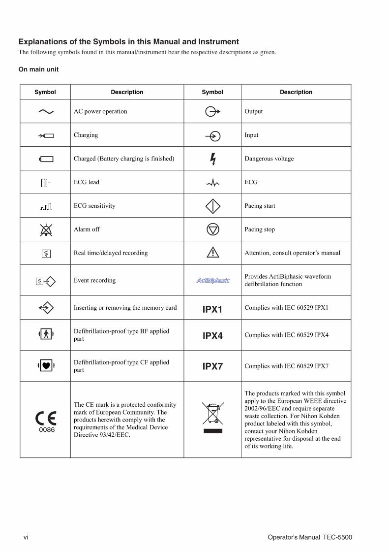
Explanations of the Symbols in this Manual and InstrumentThe following symbols found in this manual/instrument bear the respective descriptions as given.
On main unit
IPX1
IPX7
IPX4
Symbol Description Symbol Description
AC power operation Output
Charging Input
Charged (Battery charging is finished) Dangerous voltage
ECG lead ECG
ECG sensitivity Pacing start
Alarm off Pacing stop
Real time/delayed recording Attention, consult operator’s manual
Event recording Provides ActiBiphasic waveform defibrillation function
Inserting or removing the memory card Complies with IEC 60529 IPX1
Defibrillation-proof type BF applied part Complies with IEC 60529 IPX4
Defibrillation-proof type CF applied part Complies with IEC 60529 IPX7
The CE mark is a protected conformity mark of European Community. The products herewith comply with the requirements of the Medical Device Directive 93/42/EEC.
The products marked with this symbol apply to the European WEEE directive 2002/96/EEC and require separate waste collection. For Nihon Kohden product labeled with this symbol, contact your Nihon Kohden representative for disposal at the end of its working life.
Operator's Manual TEC-5500 vii
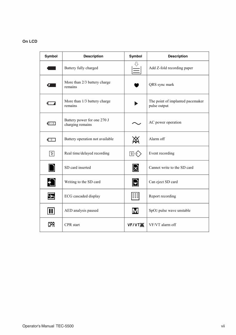
On LCD
1 3
0
Symbol Description Symbol Description
Battery fully charged Add Z-fold recording paper
More than 2/3 battery charge remains QRS sync mark
More than 1/3 battery charge remains The point of implanted pacemaker
pulse output
Battery power for one 270 J charging remains AC power operation
Battery operation not available Alarm off
Real time/delayed recording Event recording
SD card inserted Cannot write to the SD card
Writing to the SD card Can eject SD card
ECG cascaded display Report recording
AED analysis paused SpO2 pulse wave unstable
CPR start VF/VT alarm off

viii Operator's Manual TEC-5500
This page is intentionally left blank.

Operator's Manual TEC-5500 1C.1
Section 1 General
Introduction .........................................................................................................................1.1
Models and Functions ...............................................................................................1.1
Features ....................................................................................................................1.2
Composition ........................................................................................................................1.3
Caution Label and Caution Mark ..........................................................................................1.4
Panel Description ................................................................................................................1.5
Front Panel ................................................................................................................1.5
Top Panel (only for TEC-5531) ...................................................................................1.6
External Paddles .......................................................................................................1.7
Left Side Panel ..........................................................................................................1.7
Rear Panel ................................................................................................................1.8
Important Safety Information ..............................................................................................1.9
Recording Sound ............................................................................................................... 1.27

1C.2 Operator's Manual TEC-5500
This page is intentionally left blank.

1. GENERAL
Operator's Manual TEC-5500 1.1
Introduction
Models and Functions
This instrument is a portable defibrillator with functions necessary for
cardiopulmonary resuscitation treatment by biphasic defibrillation waveform. In
AED mode, if the defibrillator detects a shockable rhythm in ECG analysis, it
automatically charges energy to prepare for defibrillation (AED function). This
helps doctors who are inexperienced in defibrillation to perform defibrillation
easily. This defibrillator can use either AC power operation or optional battery
operation according to where it is used. With an optional DSI interface unit or
DSI/AUX OUT interface unit, SpO2 and CO2 monitoring are available with this
defibrillator, which enables continuous monitoring of the patient after defibrillation
or cardioversion.
Functions TEC-5521 TEC-5531
External paddles Standard Standard
Internal paddles Option Option
Disposable pads Option Option
Defibrillation and synchronized cardioversion
Pediatric electrode assy 44 mm φ Option Option
3 lead ECG Standard Standard
AED function Standard Standard
Noninvasive pacing Not available Standard
SpO2 measurement Option Option
CO2 measurement Option Option
Voice prompt Standard Standard
5 lead ECG Option Option
External ECG input Option Option
External ECG output Option Option
SD card slot Standard Standard
Sound recording Standard Standard

1. GENERAL
1.2 Operator's Manual TEC-5500
1. Biphasic waveform defibrillation
The defibrillator provides biphasic waveform defibrillation. Biphasic
waveform defibrillation requires low energy than conventional monophasic
defibrillation.
2. Display
The display is 5.7 inch color LCD. ECG waveforms and messages are easy to
see. You can select either 25 or 50 mm/sec for sweep speed.
3. Selectable power sources, AC/ Battery
Either AC or battery power can be selected according to where it is used.
4. Fast charging
Charges from 0 to 270 J within 5 seconds in both AC and battery operation
(with a fully charged new battery at 20°C). Charges from 0 to 200 J within 3
seconds in both AC and battery operation. This enables timely defibrillation
and cardioversion.
5. Quick ECG waveform recovery
After defibrillation or cardioversion the ECG waveform returns within 3
seconds so you can immediately check the result of defibrillation or
cardioversion.
6. AED function
During ECG analysis, if the defibrillator detects a shockable rhythm, it
automatically charges energy to prepare for the next defibrillation.
7. Noninvasive pacing (only for TEC-5531 series defibrillator)
The TEC-5531 series defibrillator has noninvasive pacing. This is useful for
first aid for bradycardia that often appears after defibrillation.
8. SpO2 and CO2 monitoring
With the optional DSI interface unit or DSI/AUX OUT interface unit, SpO2 and
CO2 can be monitored on the defibrillator.
9. Voice prompt
This function is mainly used in AED mode. Defibrillator status and cautions
during defibrillation are directed by voice.
10. Basic function check
The defibrillator has a semi-automatic self check function for discharge,
battery, recording, alarm sound and voice. These checks are performed on one
screen. You can easily check the defibrillator before use.
13. SD card
With a specified SD card, report data and surrounding sound together with the
ECG waveforms can be recorded and transferred to a personal computer.
Features

1. GENERAL
Operator's Manual TEC-5500 1.3
Composition
TEC-5500 Series Defibrillator
Disposable pads P-510 Internal paddles
Standard accessories
Options
Cart KD-028ACart tray assembly DI-001A
SpO2 adapter JL-951T3 CO2 sensor kit TG-901T3
OPER/ALARM
CO2 ADAPTER
JG-901T3 CO2 adapter
TG-101T CO2 sensor
HOPER/ALARM
CO2 ADAPTER
TG-121T CO2 sensor
JG-921T3 CO2 adapter
CO2 sensor kit TG-921T3
Name Qíty Recording paper (Z-fold) 1 Contact gel GELAID 1 Battery check label (for defibrillator) 1
Name TEC accessory set (100V/IEC) BC-763V ECG connection cable (IEC, 3 leads) + Power cord H
TEC accessory set (200V/IEC) BC-763V ECG connection cable (IEC, 3 leads) + Power cord N
TEC accessory set (100V/AHA) BC-763VA ECG connection cable (AHA, 3 leads) + Power cord H
TEC accessory set (200/AHA) BC-763VA ECG connection cable (AHA, 3 leads) + Power cord N
QI-552V DSI interface unit
QI-553V DSI/AUXOUT interface unit

1. GENERAL
1.4 Operator's Manual TEC-5500
Caution Label and Caution Mark
This indicates cautions labels, caution marks on the instrument and where the
related explanations are.
WARNINGConnect only the specified instrument to the defibrillator and follow
the specified procedure. Failure to follow this warning may result in
electrical shock or injury to the patient and operator, and cause fire or
instrument malfunction.
Refer to Section 5 “Pacing”
Refer to Section 4 “Defibrillation, SynchronizedCardioversion and AED”, “ECG Monitoring” in Section6 “Monitoring” and Section 9 “Messages andTroubleshooting”
Left side panel:Refer to “Using the Battery” and“Loading the Recording Paper” inSection 2 “Preparation”.
Refer to “ECG Monitoring”in Section 6.
Refer to “SpO2 Monitoring” and “CO2 Monitoring”in Section 6 .
Refer to Section 4 “Defibrillation,Synchronized Cardioversion and AED”
1. GENERAL
Operator's Manual TEC-5500 1.5
12
4
5
7
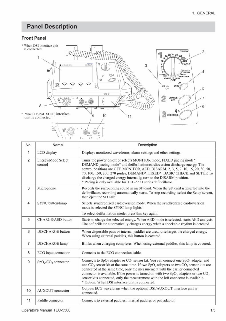
Panel Description
Front Panel
* When DSI/AUXOUT interfaceunit is connected 10
1
8
9 11
* When DSI interface unit is connected
6
3
No. Name Description
1 LCD display Displays monitored waveforms, alarm settings and other settings.
2 Energy/Mode Select control
Turns the power on/off or selects MONITOR mode, FIXED pacing mode*, DEMAND pacing mode* and defibrillation/cardioversion discharge energy. The control positions are OFF, MONITOR, AED, DISARM, 2, 3, 5, 7, 10, 15, 20, 30, 50, 70, 100, 150, 200, 270 joules, DEMAND*, FIXED*, BASIC CHECK and SETUP. To discharge the charged energy internally, turn to the DISARM position. * Pacing is only available for TEC-5531 series defibrillator.
3 Microphone Records the surrounding sound in an SD card. When the SD card is inserted into the defibrillator, recording automatically starts. To stop recording, select the Setup screen, then eject the SD card.
4 SYNC button/lamp Selects synchronized cardioversion mode. When the synchronized cardioversion mode is selected the SYNC lamp lights. To select defibrillation mode, press this key again.
5 CHARGE/AED button
Starts to charge the selected energy. When AED mode is selected, starts AED analysis. The defibrillator automatically charges energy when a shockable rhythm is detected.
6 DISCHARGE button When disposable pads or internal paddles are used, discharges the charged energy. When using external paddles, this button is covered.
7 DISCHARGE lamp Blinks when charging completes. When using external paddles, this lamp is covered.
8 ECG input connector Connects to the ECG connection cable.
9 SpO2/CO2 connector Connects to SpO2 adapter or CO2 sensor kit. You can connect one SpO2 adapter and one CO2 sensor kit at the same time. If two SpO2 adapters or two CO2 sensor kits are connected at the same time, only the measurement with the earlier connected connector is available. If the power is turned on with two SpO2 adapters or two CO2 sensor kits connected, only the measurement with the left connector is available. * Option: When DSI interface unit is connected.
10 AUXOUT connector Outputs ECG waveforms when the optional DSI/AUXOUT interface unit is connected.
11 Paddle connector Connects to external paddles, internal paddles or pad adaptor.

1. GENERAL
1.6 Operator's Manual TEC-5500
Top Panel(only for TEC-5531)
3
4
1
5
20
19
12
13
14 15 16 17
18
2
6
No. Name Description
12 Record key Starts recording with the recorder. To stop recording, press this key again.
13 Event key Starts event recording. When this key is pressed, the recorded waveforms are saved as an event in the summary recording data.
14 ECG lead key Changes ECG leads. 15 ECG sensitivity key Changes ECG sensitivity. 16 Silence alarms key Temporarily suspends or silences alarms. 17 Multi-function key In the monitor mode, opens the alarm setup screen. You can
confirm or change alarm settings. In AED mode this key changes to Pause key.
18 AC lamp Lights when AC power is supplied to the defibrillator. 19 Battery charging lamp Lights when the battery is being charged.
20 Battery charge complete lamp
Lights when the battery is completely charged.
No. Name Description
1 PACING RATE Up key Increases the pacing frequency (pulse/minute). 2 PACING RATE Down
key Decreases the pacing frequency (pulse/minute).
3 PACING OUTPUT Up key
Increases the intensity of the pacing current.
4 PACING OUTPUT Down key
Decreases the intensity of the pacing current.
5 START/STOP key Press to start pacing. Pressing this key again stops pacing. 6 PULSE lamp Blinks in synchronization with the pacing pulse.

1. GENERAL
Operator's Manual TEC-5500 1.7
Left Side Panel
External Paddles
1
44
32
1
4 3
2
No. Name Description
1 CONTACT lamp Indicates the quality of contact between paddles and patient. The GOOD lamp must light.
2 CHARGE button Press to charge the selected energy. 3 CHARGE lamp Blinks while the selected energy is being charged. Lights when
the energy is completely charged. 4 DISCHARGE buttons Simultaneously press both buttons to discharge the charged
energy. In synchronized cardioversion, the defibrillator discharges energy at the appropriate timing after these buttons are pressed.
No. Name Description
1 Recording paper exit The recorded paper comes from this slit. A cutter to cut the paper is attached here.
2 Door release lever Pull the lever up to open the door. 3 SD card slot Insert an SD card here. To remove the card, push it in. 4 Battery pack holder Contains the battery.

1. GENERAL
1.8 Operator's Manual TEC-5500
Rear Panel
1 2
No. Name Description
1 AC SOURCE socket Connects the AC power cord to supply AC power. 2 Optional unit connector Optional unit is connected. When not used, attach the cover
here.

1. GENERAL
Operator's Manual TEC-5500 1.9
Important Safety Information
GeneralDANGER
• Never use the defibrillator in the presence of any flammable
anesthetic gas or high concentration oxygen atmosphere. Failure to
follow this warning may cause explosion or fire.
• Never use the defibrillator in a hyperbaric oxygen chamber. Failure
to follow this warning may cause explosion or fire.
WARNING• The defibrillator generates high voltage. The defibrillator must only
be operated by trained and qualified medical personnel.
• Radiofrequency or Electromagnetic Field
Do not use any kind of non-essential non-patient care device within a
radius of 1 meter around the defibrillator. The use of non-essential
non-patient care devices that emit radiofrequency or
electromagnetic fields may interfere with the operation of the
defibrillator by causing noise on the ECG waveform or error
messages. If a non-essential non-patient care device is accidentally
placed near the defibrillator, quickly remove it.
• MRI examination
- Do not install this defibrillator in an MRI examination room. The
defibrillator may not operate properly due to high-frequency
magnetic noise from the MRI.
- When performing MRI tests, remove all electrodes and transducers
from the patient which are connected to this defibrillator. Failure
to follow this warning may cause serious electrical burn on the
patient due to local heating caused by dielectric electromotive
force. For details, refer to the instruction manual for the MRI.
• Using with ESU
- When the defibrillator is used with an electrosurgical unit (ESU),
firmly attach the entire area of the ESU return plate. Otherwise,
the current from the ESU flows into the electrodes of the
defibrillator, causing electrical burn where the electrodes are
attached. For details, refer to the ESU manual.
- When using an ESU, use this defibrillator only in the MONITOR
mode and use the ECG electrodes for monitoring. Do not monitor
ECG with disposable pads, external paddles or internal paddles. If
ECG is monitored with pads or paddles, high frequency energy
from the ESU causes abnormal current to flow in the patient and
unexpected discharge. This may damage the defibrillator.
1. GENERAL
1.10 Operator's Manual TEC-5500
Installation
WARNING continued• Surrounding Conditions
Fluids such as Ringer’s saline solution and blood are excellent
electrical conductors; to avoid creating potentially dangerous
electrical paths, keep the defibrillator and the immediate area clean
and dry at all times.
CAUTION• Install the defibrillator and ESU appropriately and perform
equipotential grounding. Otherwise, noise from the ESU may be
falsely recognized as QRS and ECG monitoring might not be
performed properly.
• Only use Nihon Kohden specified parts and accessories. When other
parts or accessories are used, the defibrillator heats up and may be
damaged, and monitoring stops.
• Do not reuse disposable items.
• Turn off the power of cellular telephones, small wireless devices and
other devices which produce strong electromagnetic interference.
Otherwise, the waveforms and measurements are affected by
interference and the displayed data may be incorrect.
WARNING• Connect only the specified instrument to the defibrillator and follow
the specified procedure. Failure to follow this warning may result in
electrical shock or injury to the patient and operator, and cause fire
or instrument malfunction.
• Only use the provided power cord. Using other power cords may
result in electrical shock or injury to the patient and operator.
• Only use the provided power cord. When the provided power cord
cannot be used or when equipotential grounding is doubtful (such as
in poor grounding facility), operate the defibrillator on battery
power. Otherwise, the patient and operator may receive electrical
shock or injury.
• When several medical instruments are used together, ground all
instruments to the same one-point ground. Any potential difference
between instruments may cause electrical shock to the patient and
operator.
• Do not connect several grounding leads directly to the equipotential
terminal because the grounding lead may be disconnected from the
terminal.

1. GENERAL
Operator's Manual TEC-5500 1.11
Battery
CAUTION• The defibrillator should only be connected to external equipment
which complies with the CISPR 11 Second Edition 1990-09, Group 1
and Class B standard.
• Only use the KD-028A cart for this defibrillator. If another cart is
used, it may tip over or the defibrillator may fall off.
• Assembly and disassembly of any component in the instrument
should only be done by qualified service personnel.
DANGER• Keep the battery pack away from fire. Do not heat the battery pack.
If the battery pack is heated, the substance inside the battery squirts
out and the battery pack explodes.
• Never connect the + and – terminals on the battery pack with a wire.
Never store the battery pack with metals such as necklace or hair
pins. The battery pack may short-circuit, causing the substance
inside the battery to leak or explode.
• Never disassemble or modify the battery pack. Never damage or
directly solder the sheath tube. The battery pack may short-circuit,
the substance inside the battery may squirt out and the battery pack
may explode.
• Do not subject the battery pack to a strong shock. The battery may
leak and explode.
• Do not use a battery which is damaged, such as from falling. The
battery has a gas discharge valve and if this valve is damaged, the
gas cannot be discharged, causing the battery to explode.
• If the battery pack is damaged and the substance inside the battery
(alkaline liquid) contacts the eyes or skin, wash immediately and
thoroughly with water and see a physician. Never rub your eyes,
because you may lose your eyesight.
• The battery pack has + and – polarity. Make sure that the battery is
installed in the correct direction. Do not connect the battery with
force if it cannot be connected easily. If the battery is connected with
the wrong polarity, the substance inside the battery may leak and
explode.
• Do not charge the battery pack with an instrument other than this
defibrillator. With another instrument, abnormal current flows and
the battery may leak and explode.
• Do not connect the battery pack to an AC outlet or lighter socket in a
car. The battery may leak and explode.

1. GENERAL
1.12 Operator's Manual TEC-5500
WARNING• Test the battery once a month.
• When you start using a new battery pack, write the date of first use
on the labels on the battery pack and defibrillator.
• Replace the battery pack every year.
• If defibrillation or cardioversion is necessary during the battery test,
cancel the battery test and operate the defibrillator on AC power. Do
not use battery power because the battery may have been
discharged by the battery test.
• Do not immerse the battery pack in water. The battery heats up and
rusts and the substance inside the battery leaks.
• Never use a battery pack which is damaged, discolored or has
leakage. The battery may explode if used.
• Do not leave the battery unused for more than about one year. The
battery may leak.
CAUTION• When inserting or removing the battery, disconnect the power cord
from the defibrillator. Otherwise, the operator may receive electrical
shock.
• To keep the battery fully charged, always keep the power cord
connected to the AC outlet even when the defibrillator is not used.
Otherwise, the battery may discharge and become unusable.
• Do not expose the battery pack to direct sunlight or leave in a high
temperature place. The lifetime of the battery pack may be
shortened, the performance of the battery pack may be degraded
and the battery may leak.
• The battery pack must be inserted by a qualified service personnel.
• Keep the battery pack away from children.
NOTEBefore disposing of the battery, check with your local solid waste
officials for details in your area for recycling options or proper
disposal. The battery is recyclable. At the end of its useful life, under
various state and local laws, it may be illegal to dispose of this battery
into the municipal waste stream.

1. GENERAL
Operator's Manual TEC-5500 1.13
Disposable PadsWARNING
• Failure to follow the warnings below may cause skin burn or
insufficient energy discharge and insufficient pacing current to the
heart.
- Do not reuse disposable pads.
- If the pad package is torn, dispose of the pads and do not use
them.
- Do not use the pads if they are past the expiration date on the
package.
- Use the disposable pads as soon as possible after opening the
package.
- Do not use the disposable pads if the gel has become dry or if the
gel has become abnormal (the gel has become liquid or is coming
off the edges of the pad, etc).
- Do not use the disposable pads if the gel is dark brown or dark
brown gel is on the protective sheet.
• If any pad or connector gets wet, replace it with a new one. If a wet
pad or connector is used, it may cause electrical shock.
• When using the disposable pads for long term pacing, replace them
every hour. Failure to follow this warning may cause skin burn or
insufficient energy discharge and pacing current to the heart.
CAUTION• When using the disposable pads for long term ECG monitoring,
replace them every 24 hours. Failure to follow this instruction may
cause insufficient pacing current and insufficient energy discharge to
the heart.
• Do not attach a disposable pad over another pad. It may cause skin
burn on the patient.
• Do not put heavy objects on the disposable pads or bend the pads. If
the pads get damaged or deteriorated, it may cause skin burn on the
patient.

1. GENERAL
1.14 Operator's Manual TEC-5500
Defibrillation,Cardioversion and AED
General
WARNING• Before defibrillation and cardioversion, make sure that no one is in
contact with either the patient or any metal part of any equipment or
cables which supports or is connected to the patient. Failure to
follow this warning causes serious electrical shock or injury.
• Before defibrillation and cardioversion, remove from the patient all
electrodes, probes and transducers from a connector that do not
have a “ ” or “ ” mark. Otherwise, the operator may receive
electrical shock and the connected instrument may be damaged.
• Before defibrillation and cardioversion, remove everything
(electrodes, patches, etc.) from the patient’s chest. When the
defibrillator paddle directly contacts these materials, the discharged
energy may cause skin burn to the patient.
• Before defibrillation and cardioversion, check that the cords and
cables of the electrodes, probes and transducers attached to the
patient are properly connected to a connector that has a “ ” or
“ ” mark. Touching the metal parts of the disconnected cords and
cables may cause electrical shock or injury by discharged energy.
• Do not move the defibrillator when any charged energy remains in
the defibrillator. If the defibrillator receives any impact, such as
from falling, it discharges energy that can cause electrical shock.
• For this defibrillator, the CONTACT lamp on the STERNUM paddle
indicates skin-paddle contact impedance. If the yellow or orange
lamp lights, the defibrillator may cause serious electric burn on the
patient’s skin and poor energy discharge to the patient. In case of
an emergency, medical personnel should decide whether to execute
discharge immediately, regardless of the CONTACT lamp display, or
take action to make good contact before discharge.
• Pay careful attention to the selected energy when using the pediatric
electrode plates. Applying high energy with the pediatric electrode
plates can cause skin burn because the electrode plates are small.
• Use the ECG monitoring electrodes (disposable electrodes) to
monitor the ECG waveforms. Stable ECG cannot be acquired with
the PADDLE lead because it is difficult to hold the paddles stable.
ECG acquired from external paddles, internal paddles or disposable
pads is unstable after discharge because of high polarization
voltage.
• Do not perform defibrillation or cardioversion in a wet place. Before
defibrillation or cardioversion, move the patient and defibrillator to a
dry place. Otherwise the operator may get electrical shock.
• Never discharge near a person or object other than the patient or
test electrode plate or energy checker. It may cause electrical shock
to the person or damage the object.
• Confirm that there is no noise on the ECG. Noise may be
misrecognized as QRS and discharge might not synchronize with the
patient’s QRS.

1. GENERAL
Operator's Manual TEC-5500 1.15
WARNING continued• Do not perform synchronized cardioversion with the PADDLE lead
unless it is absolutely necessary. In synchronized cardioversion with
the PADDLE lead, noise may be misrecognized as QRS and
discharge might not synchronize with the patient’s QRS.
• Never select “TEST” for the ECG lead. “TEST” is for maintenance
and the waveform displayed on the screen is not the patient’s ECG.
If synchronized cardioversion is performed with the TEST lead, the
discharge is not synchronized with the patient’s QRS and it may
cause ventricular fibrillation.
• If you use the ECG signal from the monitor, before cardioversion,
check that the defibrillator discharge occurs within 60 ms of the peak
of the ECG’s R wave with a delivery checker. If this condition is not
met, the cardioversion may be ineffective or may cause ventricular
fibrillation.
• The apex-posterior placement is not suitable for ECG monitoring or
AED analysis.
• The anterior-posterior placement is not suitable for ECG monitoring
or AED analysis. Use this placement only for pacing.
• Make sure to push the connector of each paddle into the paddle
connector deeply until it clicks. If the connector is not properly
connected, the "Connect paddle" message might not be displayed,
the connector may be disconnected, and the energy might not be
discharged.
• Pay careful attention to the selected energy when performing
defibrillation on children. Performing defibrillation with high energy
may cause fatal damage to the heart.
CAUTION• When performing synchronized cardioversion, confirm that the SYNC
lamp is lit before every discharge. If “Sync mode after CV” is set to
Defib on the System Setup - Configuration screen, the defibrillator
automatically turns to the asynchronous defibrillation mode.
• Have another defibrillator ready in case of defibrillator failure.
When using another defibrillator, remove the paddles of the failed
defibrillator from the patient.
1. GENERAL
1.16 Operator's Manual TEC-5500
With External Paddles
WARNING• Apply contact gel only to the electrode plates of the external
paddles. Otherwise, it may cause electrical shock to the operator.
• Do not apply contact gel by hand. Failure to follow this warning may
cause serious electrical burn, shock, or other injury.
• Do not hold the paddle handles if your hands are wet or have
contact gel on them. This may cause electrical shock to the
operator.
• To avoid skin burn on the patient and poor energy discharge to the
heart, apply contact gel to the electrode plates of the external
paddles.
• Do not touch the electrode plate or edge of the paddle. Failure to
follow this warning may cause serious electrical burn, shock, or
other injury.
• When charging or discharging, do not touch anything other than the
handles. If any other part of the defibrillator is touched during
charging or discharging, the operator receives an electrical shock.
• Before discharging, confirm that the paddles are firmly pressed
against the chest wall. Failure to follow this warning causes skin
burn or poor energy discharge to the heart.
• Do not discharge with the paddles in the air. This may cause
electrical shock to the operator or damage the defibrillator.
• Do not discharge the energy if the paddles are shorted to each other
by contact gel. It may cause skin burn and poor energy discharge to
the heart.
CAUTION• When using the external paddles, connect it to the paddle connector
until it clicks. After connecting the external paddles, use the Basic
checks screen to check that the defibrillator charges and discharges
energy properly. If the energy is not discharged, the connector of
the external paddles is not firmly connected to the paddle connector.
In this case, push the connector of the external paddles into the
paddle connector deeply until it clicks.
• If the patient’s body is wet, thoroughly wipe the moisture off the skin
so that the paddles do not short to each other.
• Do not discharge when the paddles touch each other. This may
damage the defibrillator.

1. GENERAL
Operator's Manual TEC-5500 1.17
guard
With Disposable Pads
WARNING• Do not attach pads on the papilla, electrodes or medicine on the
patient’s body. Failure to follow this warning causes serious skin
burn.
• Fit the pad closely to the body surface so that current flows uniformly
through the pad. Failure to follow this warning causes serious skin
burn or insufficient energy discharge to the heart.
• During charging or discharging, do not touch the pads or connectors.
Failure to follow this warning causes electrical shock to the operator.
• Before discharging, confirm that the pads are firmly applied to the
chest wall. Failure to follow this warning causes skin burn or poor
energy discharge to the heart.
• Do not discharge if the pads overlap each other or are shorted to
each other by anything conductive such as contact gel. This may
cause skin burn and poor energy discharge to the heart.
CAUTION• When connecting the pad adapter to the paddle connector, do not
bend or damage the connector pin. Energy cannot be discharged to
the pads.
• If the patient’s body is wet, thoroughly wipe the moisture off the skin
so that the pads do not short to each other.
With Internal Paddles
WARNING• Sterilize the internal paddles before use. Failure to sterilize the
paddles may cause serious infection.
• Pay careful attention to the selected energy when using internal
paddles. Applying high energy to the heart may cause cardiac
muscle necrosis. Low energy is recommended.
• During charging and discharging, grip the internal paddles between
the guard at the top of the handle and the cable. If you grip the
handle between the electrode and the guard, you may get an
electrical shock.
• Before discharging, confirm that the paddles are firmly positioned
against the heart. Failure to follow this warning causes serious skin
burn or poor energy discharge to the heart.
• Do not discharge with the paddles in the air. This may cause
electrical shock to the operator or damage the defibrillator.

1. GENERAL
1.18 Operator's Manual TEC-5500
CAUTION• Do not twist the internal paddle while holding the electrode or give
strong impact to the paddle. It damages the electrode.
• When connecting the internal paddles to the paddle connector, do
not bend or damage the connector pin. Otherwise energy cannot be
discharged to the paddles.
• Do not discharge when the paddles touch each other. This may
damage the defibrillator.
AED
WARNING• Do not attach pads on the papilla, electrodes or medicine on the
patient’s body. Failure to follow this warning causes serious skin
burn.
• Fit the pad closely to the body surface so that current flows uniformly
through the pad. Failure to follow this warning causes serious skin
burn or insufficient energy discharge to the heart.
• When you perform defibrillation in an ambulance, stop the car.
• During charging or discharging, do not touch the pads or
connectors. Failure to follow this warning cause electrical shock to
the operator.
• Before discharging, confirm that the pads are firmly applied to the
chest wall. Failure to follow this warning causes skin burn or poor
energy discharge to the heart.
• Do not discharge if the pads overlap each other or are shorted to
each other by anything conductive such as contact gel. This may
cause skin burn and poor energy discharge to the heart.
CAUTION• Before AED analysis or defibrillation, confirm that the patient is
unconscious and has no respiration and no pulse.
• The ECG of a child or a patient with an implanted pacemaker cannot
be analyzed correctly. For these patients, follow the physician’s
instruction.
• Before AED analysis, if the ECG baseline wanders, remove the
causes. Otherwise, correct analysis result cannot be obtained.
• During AED analysis, stop life saving treatment such as CPR. Do not
touch or move the patient, pad adapter and disposable pad cable.
Correct analysis result cannot be obtained.
• When connecting the pad adapter to the paddle connector, do not
bend or damage the connector pin. Energy cannot be discharged to
the pads.
• If the patient’s body is wet, thoroughly wipe the moisture off the skin
so that the pads do not short to each other.

1. GENERAL
Operator's Manual TEC-5500 1.19
Pacing
CAUTION continued• Do not discharge when the paddles touch each other. This may
damage the defibrillator.
• Asystole is not judged to be a shockable rhythm and the defibrillator
does not automatically charge the energy.
WARNING• Do not perform pacing while using an ESU. Before using the ESU,
turn the defibrillator power off and remove disposable pads from the
patient. Otherwise, high frequency energy from the ESU causes
abnormal current to flow into the patient and causes electrical burn,
shock or other injury. It also damages the defibrillator.
• Always monitor the ECG waveform with the ECG connection cable
and ECG electrodes.
• Confirm that there is no noise on the ECG. Noise may be
misrecognized as QRS and correct pacing cannot be performed.
• Do not touch the patient, pads or connectors during pacing. It may
cause electrical shock.
• The pacing rate must be determined by qualified medical personnel
based on the heart rate of the patient in a normal state.
• The pacing current must only be increased by qualified medical
personnel decision.
• Keep the current intensity as low as possible to minimize pain and
discomfort to the patient.
• Failure to follow the following warnings causes serious skin burn.
- Do not attach the pads over ECG electrode.
- Do not attach pads on the papilla or medicine on the patient’s
body.
- Fit the pad closely to the body surface so that current flows
uniformly through the pad. This reduces the required pacing
current and pain and discomfort to the patient.
• The apex-posterior placement is not suitable for ECG monitoring or
AED analysis.
• The anterior-posterior placement is not suitable for ECG monitoring
or AED analysis. Use this placement only for pacing.
• Never select “TEST” for the ECG lead. “TEST” is for maintenance
and the waveform displayed on the screen is not the patient's ECG.
• Do not change the sensitivity or ECG lead setting after pacing is
started. If one of these settings is changed, the pacing stops for 3
seconds. Failure to follow this warning may cause serious heart
attack.
• No QRS wave is detected:
- For 240 ms after the pacing pulse is output, if the pacing rate is set
to 100 ppm or more.
- For 350 ms after the pacing pulse is output, if the pacing rate is set
to 90 ppm or less.

1. GENERAL
1.20 Operator's Manual TEC-5500
ECG Monitoring
CAUTION• Check that the pacing pulse is effective by observing ECG on the
screen.
• When connecting the pad adapter to the paddle connector, do not
bend or damage the connector pin. Energy cannot be discharged to
the pads.
• If the patient’s body is wet, thoroughly wipe the moisture off the skin
so that the pads do not short to each other.
WARNING• When using a defibrillator together with the monitor, use Ag/AgCl
electrodes. Other types of electrodes, stainless steel in particular,
will adversely affect the ECG waveform by slowing the baseline
recovery on the monitor and result in no monitoring immediately
following defibrillation.
• Keep pacemaker patients under close observation. The pacemaker
rate may be counted during cardiac arrest and certain arrhythmias.
Do not rely only on heart rate alarms and the displayed heart rate.
• The apex-posterior placement is not suitable for ECG monitoring or
AED analysis.
• The anterior-posterior placement is not suitable for ECG monitoring
or AED analysis. Use this placement only for pacing.
• With the pacing pulse rejection ON, narrow width QRS of a
premature baby or infant cannot be detected correctly and the
defibrillator may miscount QRS. In this case, set the pacing pulse
rejection to OFF.
• Turn the pacing pulse rejection to OFF when monitoring a child.
With the pacing pulse rejection ON, narrow width QRS of a child
cannot be detected correctly and the defibrillator may miscount
QRS.
CAUTION• When the “Check ECG Electrodes” message is displayed, ECG is not
monitored properly and the ECG alarm does not function. Check the
electrode, electrode leads and connection cord, and if necessary,
replace with new ones.
• Turn the pacing pulse rejection to On when monitoring a pacemaker
patient. Otherwise QRS and pacemaker spike might not be
distinguished and pacing failure might not be recognized.

1. GENERAL
Operator's Manual TEC-5500 1.21
SpO2 MonitoringWARNING
• SpO2 Measurement may be incorrect in the following cases.
- When the patient’s carboxyhemoglobin or methemoglobin
increases abnormally
- When dye is injected in the blood
- When using an electrosurgical unit
- During CPR
- When measuring at a site with venous pulse
- When there is body movement
- When the pulse wave is small (insufficient peripheral circulation)
• When not monitoring SpO2, disconnect the SpO2 connection cord
from the bedside monitor. Otherwise, noise from the probe sensor
may interfere and incorrect data is displayed on the screen.
• Check the circulation condition by observing the skin color at the
measurement site and pulse waveform. Change the measurement
site every 8 hours. The skin temperature may increase at the
attached site by 2 or 3°C (4 or 5°F) and cause a burn or pressure
necrosis. When using the probe on the following patients, take
extreme care and change the measurement site more frequently
according to symptoms and degree.
- Patient with a fever
- Patient with a peripheral circulation insufficiency
- Neonate or low birth weight infant with delicate skin
• When using probes other than the TL-201T finger probe, to avoid
poor circulation, do not wrap the tape too tight. Check the blood
circulation condition by observing the skin color and congestion at
the skin peripheral to the probe attachment site. Even for short-term
monitoring, there may be burn or pressure necrosis from poor blood
circulation, especially on neonates or low birth weight infants whose
skin is delicate. Accurate measurement cannot be performed on a
site with poor peripheral circulation.
• When measuring SpO2 of a patient who is in a state of shock or in
CPR (cardiopulmonary resuscitation), the acquired SpO2 data may be
incorrect due to the patient’s body movement.
• Do not use the probe during MRI examination because it may cause
skin burn on the probe attachment area. For details, follow the MRI
operator’s manual.

1. GENERAL
1.22 Operator's Manual TEC-5500
CAUTION• For long term monitoring, check the circulation condition by
observing the skin color the measureing site. To avoid circullation
insufficiency and skin burn, change the measurement site every
specified hours. Reffer to the operator’s manual of the plobe you
use.
• Do not pull or bend the probe cable, and do not put caster feet on
the probe cable. Do not immerse the probe cable in chemical
solutions or water. Failure to follow these instructions may cause
cable discontinuity, short circuit, skin burn on the patient and
incorrect measurement data. Replace any broken probe with a new
one.
• Turn off the power of mobile phones, small wireless devices and
other devices which produce strong electromagnetic interference
around a patient (except for devices allowed by the hospital
administrator). Radio waves from devices such as mobile phones or
small wireless devices may be mistaken as pulse waves and the
displayed data may be incorrect.
• Only use the specified probes. Otherwise SpO2 cannot be monitored
properly and instrument performance may be degraded.
• Do not use a probe which is past the expiration date on the package.
• Do not use a damaged or disassembled probe. It causes incorrect
measurement and may injure the patient.
• The disposable probe is not sterilized. Use the disposable probe only
for a single patient. Never reuse the disposable probe for another
patient because it causes cross infection.
• If the attachment site is dirty with blood or bodily fluids, clean the
attachment site before attaching the probe. If there is nail polish on
the attachment site, remove the polish. Otherwise, the amount of
transmitted light decreases, and measured value may be incorrect or
measurement cannot be performed.
• If the skin gets irritated or redness appears on the skin from the
probe, change the attachment site or stop using the probe. Take
extreme care for the patients with delicate skin.
• If the probe is attached to the same limb that is used for NIBP
measurement or an IBP catheter, the blood circulation at the
attachment site is affected and the measurement might not be
correct.
Attach the probe to a limb where the blood circulation is not
affected.
• If patient’s nail is long, cut it or attach the probe to another finger.
The probe cannot be attached properly to a finger with a long nail.
• Refer to the probe instruction manual for details.
• Neonatal skin is delicate. Remove the probe and tape carefully and
slowly.
• When removing the probe from the attachment tape, do not pull the
sensor cable because this can damage the cable.

1. GENERAL
Operator's Manual TEC-5500 1.23
CO2 Monitoring
CAUTION continued• When the probe is attached on an appropriate site with sufficient
circulation and an error message about probe attachment repeatedly
appears, the probe may be deteriorated. Replace it with a new one.
• When a message indicates a faulty probe or faulty SpO2 adapter,
stop monitoring and replace the probe or SpO2 adapter with a new
one.
• Do not use a probe which is deteriorated by aging. Accurate
measurement cannot be performed.
• Do not use disposable probes for other patients. If the probe is dirty
with blood or bodily fluids, replace it with a new one.
• While a patient is on medication which causes vasodilation, the
pulse waveform may change and in rare cases the SpO2 value might
not be displayed.
• Do not use creosol soap, glutaraldehyde, sodium hypochlorite, or
benzalkonium chloride because they damage the probe.
• Do not soak the probe in cleaning solution because it is not
waterproof.
WARNING• When performing defibrillation or cardioversion during CO2
monitoring with the CO2 sensor kit, remove the sensor from the
patient. When the sensor cannot be removed, do not touch the
sensor cable because the discharged energy may cause serious
electrical burn, shock or other injury.
• With the TG-901T3 CO2 sensor kit, measurements are based on the
assumption of no CO2 gas in the inspiration. The CO2 concentration
in the respiration is calculated by taking the CO2 concentration in
the inspiration as 0 mmHg. Therefore, measuring CO2 by connecting
the CO2 sensor kit to a patient under mouth-to-mouth respiration or
to a Jackson Rees circuit or Mapleson D circuit where CO2 gas may
be present during inspiration may result in the acquired data being
lower than the actual value.
• With the TG-901T3 CO2 sensor kit, this monitor cannot monitor CO2 of
patients weighing less than 10 kg (22 lbs).
• Before MRI examination, remove the CO2 sensor kit from the patient.
Failure to follow this warning may cause serious electrical burn on
the patient due to local heating caused by dielectric electromotive
force. For details, refer to the MRI operator’s manual.

1. GENERAL
1.24 Operator's Manual TEC-5500
CAUTION• The CO2 data may be inaccurate when monitoring a patient with an
extremely high respiration rate or irregular respiration. Read the
measured values carefully.
• Measured value may be incorrect when the operating temperature
changes greatly.
• When the “CO2 sensor not working” or “CO2 adapter abnormality”
message is displayed, check the CO2 sensor kit and replace it if
necessary. CO2 cannot be monitored while the message is
displayed.
• Follow the CAUTION label on the CO2 gas cylinder.
• When using an anesthetic instrument with a volatile anesthetic
agent, the CO2 measurement may be inaccurate.
WARNING• Do not use the airway adapter on neonates because the dead space
volume of the airway adapter is about 5 mL.
• When using the YG-101T airway adapter on children or patients with
low ventilatory amount, the CO2 may mix in the inspiration due to
the airway adapter’s dead space volume (5 mL), resulting in
inaccurate measured values or difficulty in detecting apnea.
Perform ventilation taking into consideration the 5 mL dead space
volume.
• When using the YG-121T nasal adapter on children or patients with
low ventilatory amount, the CO2 may mix in the inspiration due to
the nasal adapter’s dead space volume (1.2 mL), resulting in
inaccurate measured values or difficulty in detecting apnea.
Perform ventilation taking into consideration the 1.2 mL dead space
volume.
• When you use YG-122T together with an oxygen cannula, check that
the oxygen cannula is correctly attached on the patient by referring
to other parameters and by observing the patient periodically.
• If arterial oxygen saturation does not increase, immediately stop
using the oxygen cannula with the CO2 sensor kit and select another
way to supply oxygen.
• The only oxygen cannula that can be used with YG-122T is #1103
manufactured by HUDSON RCI. Do not use any other oxygen
cannula. Other oxygen cannulas cannot be attached and oxygen
cannot be delivered to the patient through the nostrils.
• Check that the oxygen cannula tube is not bent, broken, or blocked
by the nasal tube. If the ends of the oxygen cannula tube turn too far
up or down, it causes insufficient oxygen supply or the CO2 value
may be incorrect.
CO2 Sensor Kit and AirwayAdapter

1. GENERAL
Operator's Manual TEC-5500 1.25
CAUTION• The airway adapter/nasal adapter is non-sterilized and disposable.
Use only for a single patient and single use. Failure to follow this
instruction causes cross infection.
• Do not sterilize the airway adapter. Safety cannot be guaranteed if
the airway adapter is sterilized.
• Use the Nihon Kohden specified airway adapter.
• With the TG-901T3 CO2 sensor kit, secure the CO2 sensor to the
respiration circuit so that the transparent film of the airway adapter
is perpendicular to the floor. If the transparent film is parallel to the
floor, water droplets may get onto the transparent film and affect the
measurement accuracy.
• Failure to follow the instructions below degrades the anti-fogging
ability of the transparent film and results in incorrect measurement.
- Replace the airway adapter/nasal adapter with a new one every 24
hours.
- Replace the airway adapter/nasal adapter with a new one if blood,
sputum or mucus adhere to the transparent film.
- Do not damage the transparent film. Do not let dust or detergent
contact the transparent film. Do not touch, wipe or clean the
transparent film with fingers or cleaners.
• Never autoclave or perform EOG gas sterilization for the TG-901T3
CO2 sensor kit. It damages the CO2 sensor kit and safety cannot be
guaranteed.
• When using the YG-121T/YG-122T nasal adapter on a patient with
bleeding disorder, poor general medical condition or malnutrition,
observe the patient condition all the time. The mouth guide touches
the mouth and may cause pressure sores.
WARNING• During alarm suspension (“Alarm off” or “Alarms suspended”
message displayed), all current alarms except for instrument alarm
group 1 are turned off.
• When admitting a new patient, check the alarm settings.
CAUTION• When the alarm limit is set to OFF, there will be no alarm for that
limit. Be careful when you set the alarm limit to OFF.
• Alarms about a parameter do not occur until the measurement of the
parameter starts.
Alarms

1. GENERAL
1.26 Operator's Manual TEC-5500
Maintenance
Storage
WARNING• When performing energy discharge test, keep the paddles in the
paddle holders when discharging the energy. Do not discharge with
the paddles in the air or when the paddles are shorted. Failure to
follow this warning may cause electrical shock and damage to the
defibrillator.
• Do not discharge with the paddles in the air. This may cause
electrical shock to the operator or damage the defibrillator.
• If defibrillation or cardioversion is necessary during battery test,
cancel the battery test and operate the defibrillator on AC power. Do
not use battery power because the battery may have been
discharged by the battery test.
CAUTION• Before maintenance, cleaning or disinfection, turn the defibrillator
power off, disconnect the power cord from the AC socket and then
remove the battery from the defibrillator. Failure to follow this
instruction may result in electrical shock and defibrillator
malfunction.
• Before battery replacement, turn off the defibrillator power and
disconnect the AC power cord from the defibrillator. Otherwise, the
operator may get an electrical shock.
• Assembly and disassembly of any component in the instrument
should only be done by qualified service personnel.
CAUTION• To prevent overheating, leave the defibrillator lying flat and do not
cover it.
• Store the disposable pads in the environment described on the pads
package. If stored in an environment other than specified, the pads
become unusable.
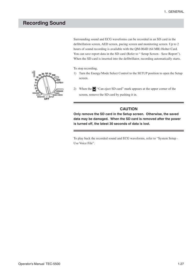
1. GENERAL
Operator's Manual TEC-5500 1.27
Surrounding sound and ECG waveforms can be recorded in an SD card in the
defibrillation screen, AED screen, pacing screen and monitoring screen. Up to 2
hours of sound recording is available with the QM-064D (64 MB) Holter Card.
You can save report data in the SD card (Refer to “ Setup Screen - Save Report”).
When the SD card is inserted into the defibrillator, recording automatically starts.
To stop recording,
1) Turn the Energy/Mode Select Control to the SETUP position to open the Setupscreen.
2) When the “Can eject SD card” mark appears at the upper corner of the
screen, remove the SD card by pushing it in.
CAUTIONOnly remove the SD card in the Setup screen. Otherwise, the saved
data may be damaged. When the SD card is removed after the power
is turned off, the latest 30 seconds of data is lost.
To play back the recorded sound and ECG waveforms, refer to “System Setup -
Use Voice File”.
Recording Sound

1. GENERAL
1.28 Operator's Manual TEC-5500
This page is intentionally left blank.

Operator's Manual TEC-5500 2C.1
Section 2 Preparation
Location ...............................................................................................................................2.1
Power ..................................................................................................................................2.2
AC Operation ............................................................................................................2.2
Battery Operation ......................................................................................................2.2
Using AC Power ..................................................................................................................2.3
Connecting the Power Cord .......................................................................................2.3
Using the Battery ................................................................................................................2.4
Safety Information about Battery Pack ......................................................................2.4
Checking the Battery Pack .............................................................................2.6
Storage ...........................................................................................................2.6
Disposal ..........................................................................................................2.6
Inserting the Battery into the Defibrillator ..................................................................2.7
Charging the Battery Pack ........................................................................................2.8
Trickle Charging .........................................................................................................2.9
Remaining Battery Power Display ........................................................................... 2.10
Loading the Recording Paper ............................................................................................. 2.11
Basic Checks .................................................................................................................... 2.12
Displaying the Basic Checks Screen ...................................................................... 2.12
Check Procedure ..................................................................................................... 2.12
Check Before Use ............................................................................................................. 2.15
Before Turning On the Power ................................................................................... 2.15
Check Items After Turning the Power On ................................................................. 2.15

2C.2 Operator's Manual TEC-5500
This page is intentionally left blank.
2. PREPARATION
Operator's Manual TEC-5500 2.1
Location
DANGER• Never use the defibrillator in the presence of any flammable
anesthetic gas or high concentration oxygen atmosphere. Failure to
follow this warning may cause explosion or fire.
• Never use the defibrillator in a hyperbaric oxygen chamber. Failure
to follow this warning may cause explosion or fire.
WARNING• Surrounding Conditions
Fluids such as Ringer’s saline solution and blood are excellent
electrical conductors; to avoid creating potentially dangerous
electrical paths, keep the defibrillator and the immediate area clean
and dry at all times.
• Radiofrequency or Electromagnetic Field
Do not use any kind of non-essential non-patient care device within a
radius of 1 meter around the defibrillator. The use of non-essential
non-patient care devices that emit radiofrequency or
electromagnetic fields may interfere with the operation of the
defibrillator by causing noise on the ECG waveform or error
messages. If a non-essential non-patient care device is accidentally
placed near the defibrillator, quickly remove it.
• Do not install this defibrillator in an MRI examination room. The
defibrillator may not operate properly due to high-frequency
magnetic noise from the MRI.

2. PREPARATION
2.2 Operator's Manual TEC-5500
Power
WARNINGOnly use the provided power cord. When the provided power cord
cannot be used or when equipotential grounding is doubtful (such as
in poor grounding facility), operate the defibrillator on battery power.
Otherwise, the patient and operator may receive electrical shock or
injury.
The defibrillator can operate on either battery or AC power. You can select either
AC or battery (Battery pack NKB-301V: option) according to where the
defibrillator is used.
When the power cord is plugged into an AC outlet, the AC lamp lights. When the
defibrillator power is turned on with the power cord connected to an AC outlet, the
defibrillator operates on AC power. The “ ” mark is displayed on the right upper
screen.
When the battery is inserted and the power cord is disconnected, such as when
transferring a patient, the defibrillator automatically switches to battery power. The
“ ” mark is displayed on the screen.
The battery can be charged only by the defibrillator. The battery is charged when
the power cord is plugged into an AC outlet and AC power is supplied to the
defibrillator. The battery is also charged during operation.
NOTEFor the TFT LCD screen, it is considered normal if some pixels have
randomly abnormal color or do not light.
AC Operation
Battery Operation

2. PREPARATION
Operator's Manual TEC-5500 2.3
Using AC Power
Connecting the PowerCord WARNING
Only use the provided power cord. Using other power cords may
result in electrical shock or injury to the patient and operator.
Connect the provided power cord to the AC SOURCE socket on the rear panel of
the defibrillator and plug the cord into a 3-prong AC outlet. When the 3-prong
power cord is connected to the 3-prong AC outlet with a ground third contact, the
defibrillator is automatically grounded.
When AC power is supplied to the defibrillator, the AC lamp lights.
NOTEIf the AC lamp does not light when the power cord is connected, check
if the power cord is properly connected.

2. PREPARATION
2.4 Operator's Manual TEC-5500
NOTEThe battery lifetime is one year. Before operating the defibrillator on
battery, check the label on the defibrillator for the date the battery was
first used.
When the battery pack NKB-301V (option) is inserted in the defibrillator and the
defibrillator is not connected to AC power, the defibrillator can be operated on
battery. When the power cord is disconnected during AC operation, the
defibrillator automatically switches to battery operation, which enables continuous
operation. When the power cord is connected again, the defibrillator switches to AC
operation automatically.
With the fully charged new battery at 20°C, the defibrillator can perform:
Defibrillation at least 70 discharges at 270 J
Monitoring at least 150 minutes continuous monitoring
Noninvasive pacing at least 90 minutes pacing in FIXED mode at 180 ppm
and 200 mA
With the fully charged new battery at 0°C, the defibrillator can perform:
Defibrillation at least 50 discharges at 270 J
DANGER• Keep the battery pack away from fire. Do not heat the battery pack.
If the battery pack is heated, the substance inside the battery squirts
out and the battery pack explodes.
• Never connect the + and – terminals on the battery pack with a wire.
Never store the battery pack with metals such as necklace or hair
pins. The battery pack may short-circuit, causing the substance
inside the battery to leak or explode.
• Never disassemble or modify the battery pack. Never damage or
directly solder the sheath tube. The battery pack may short-circuit,
the substance inside the battery may squirt out and the battery pack
may explode.
• Do not subject the battery pack to a strong shock. The battery may
leak and explode.
• Do not use a battery which is damaged, such as from falling. The
battery has a gas discharge valve and if this valve is damaged, the
gas cannot be discharged, causing the battery to explode.
• If the battery pack is damaged and the substance inside the battery
(nickel-metal hydride) contacts the eyes or skin, wash immediately and
thoroughly with water and see a physician. Never rub your eyes,
because you may lose your eyesight.
• The battery pack has + and – polarity. Make sure that the battery is
Using the Battery
Safety Information aboutBattery Pack

2. PREPARATION
Operator's Manual TEC-5500 2.5
installed in the correct direction. Do not connect the battery with
force if it cannot be connected easily. If the battery is connected with
the wrong polarity, the substance inside the battery may leak and
explode.
• Do not charge the battery pack with an instrument other than this
defibrillator. With another instrument, abnormal current flows and
the battery may leak and explode.
• Do not connect the battery pack to an AC outlet or lighter socket in a
car. The battery may leak and explode.
WARNING• Test the battery once a month.
• When you start using a new battery pack, write the date of first use
on the labels on the battery pack and defibrillator.
• Replace the battery pack every year.
• If defibrillation or cardioversion is necessary during the battery test,
cancel the battery test and operate the defibrillator on AC power. Do
not use battery power because the battery may have been
discharged by the battery test.
• Do not immerse the battery pack in water. The battery heats up and
rusts and the substance inside the battery leaks.
• Never use a battery pack which is damaged, discolored or has
leakage. The battery may explode if used.
• Do not leave the battery unused for more than about one year. The
battery may leak.
CAUTION• When inserting or removing the battery, disconnect the power cord
from the defibrillator. Otherwise, the operator may receive electrical
shock.
• To keep the battery fully charged, always keep the power cord
connected to the AC outlet even when the defibrillator is not used.
Otherwise, the battery may discharge and become unusable.
• Do not expose the battery pack to direct sunlight or leave in a high
temperature place. The lifetime of the battery pack may be
shortened, the performance of the battery pack may be degraded
and the battery may leak.
• The battery pack must be inserted by a qualified service personnel.
• Keep the battery pack away from children.
Danger - continued
2. PREPARATION
2.6 Operator's Manual TEC-5500
NOTE• Fully charge the new battery pack before using on the defibrillator.
• Do not use a battery pack which is past the expiration date written
on the label.
• If the battery pack becomes unusable or the available discharge
time has decreased, do not leave the battery pack in the
defibrillator. The substance inside the battery may leak, causing
instrument corrosion and fire. Immediately replace the battery with
a new one.
• Do not leave a battery pack inside the defibrillator without the power
cord connected between the defibrillator and AC outlet. The battery
pack may be over-discharged and can no longer be used.
• When not using the defibrillator for more than six months, remove
the battery pack from the defibrillator and store the battery at
temperatures between −−−−−20°C (4°F) and +++++35°C (95°F) and low humidity.
• Before disposing of the defibrillator, make sure that the battery pack is
removed from the defibrillator.
• Before disposing of the battery, check with your local solid waste
officials for details in your area for recycling options or proper
disposal. The battery is recyclable. At the end of its useful life, under
various state and local laws, it may be illegal to dispose of this battery
into the municipal waste stream.
Checking the Battery Pack
• In order to ensure emergency use of the defibrillator on battery power, perform
the battery test once a month.
• To prevent battery trouble, check the battery appearance every 6 months. If there
is any damage (crack, deformation, cable discontinuity and so on) on the battery
or the battery leaks, replace the battery with a new one. If the battery is dirty
with dust, remove it.
Storage
WARNINGDo not leave the battery unused for more than about one year. The
battery may leak.
• When not using the defibrillator for more than one month, to prevent leaking or
rusting of the battery, remove the battery pack from the defibrillator and store the
battery at surrounding temperatures between -20°C (4°F) and +35°C (95°F) and
low humidity.
• When a battery is not used for over one month, fully charge it before use. Even if
the battery was fully charged before storage, the battery self-discharges and
operation time decreases.
• To ensure full performance of the defibrillator, replace the battery every one year.
• When a battery is stored for a long time, the battery tends to deactivate and the
original battery capacity cannot be used to 100%. The capacity may recover by
repeating full discharging and full charging several times.

2. PREPARATION
Operator's Manual TEC-5500 2.7
* defibrillator standard accessory
** battery standard accessory
Inserting the Battery intothe Defibrillator
Before inserting the battery, check the battery appearance and write the date of first
use on the label on the battery. After inserting the battery, charge the battery.
NOTE• Use only the battery pack NKB-301V.
• Perform the battery test once a month. Check the battery appearance
every 6 months. Replace the battery every one year.
• The battery pack must be inserted by a qualified service personnel.
1. Before inserting the battery into the defibrillator, write the date of the first use
on the label on the battery.
2. Confirm that the Energy/Mode Select control is set to OFF. Disconnect the
power cord from the defibrillator.
CAUTIONWhen inserting or removing the battery, disconnect the power cord
from the defibrillator. Otherwise, the operator may receive electrical
shock.
3. Turn the knob on the battery holder cover counterclockwise and remove the
battery pack holder cover.
4. Insert the battery into the battery pack holder.
5. Securely connect the battery connector to the connector inside the battery pack
holder until it clicks and locks.
6. Close the battery pack holder cover. Be careful not to pinch the cable. Secure
the battery pack holder cover by turning the knob clockwise.
7. On the battery check label*, write the date of battery first use and the date the
battery is checked. On the start date label**, write down the date of battery
first use. Attach each label on the defibrillator so that you can see them easily,
for example, on the upper part of the right side panel.
Disposal
The battery is NiMH. Before disposing of the battery, check with your local solid
waste officials for details in your area for recycling options or proper disposal. The
battery is recyclable. At the end of its useful life, under various state and local laws,
it may be illegal to dispose of this battery into the municipal waste stream.

2. PREPARATION
2.8 Operator's Manual TEC-5500
Charging the Battery Pack The battery can be charged only by the defibrillator. When “ 0 ” appears on the
screen, immediately charge the battery. When “ 0 ” is displayed on the screen,
the defibrillator cannot charge the defibrillation or cardioversion energy. The new
battery is not charged.
NOTE• When you use a new battery, charge the battery at least 3 hours until
the battery charge complete lamp lights.
• Always charge the battery pack at surrounding temperatures between
0°C (32°F) and 40°C (104°F). Charging may stop when the battery is
charged at surrounding temperatures higher than 45°C (113°F). In this
case, move the defibrillator to a cooler place. When the battery
temperature decreases, the battery charging resumes.
• Charge the battery pack only by the defibrillator. If the battery pack is
charged with another instrument, abnormal current flows, the
substance inside the battery leaks and the battery explodes. Also it
causes defibrillator malfunction and instrument trouble.
• When charging the battery, confirm that the AC lamp is lit and either
the battery charging lamp or battery charge complete lamp is lit.
• Charge the battery pack immediately after it is used. If it is left
uncharged, the battery will become unusable because of over-
discharge.
Charging procedure
1. Set the Energy/Mode Select control to the OFF position.
2. Connect the power cord to the defibrillator. The battery charging lamp on the
front panel lights and the charging (rapid charging) starts.
NOTEDo not disconnect the power cord until charging finishes.
3. When rapid charging finishes, the battery charge complete lamp lights.
9. Reset the date of first use of the battery.
1) Display the System Setup - Battery Test screen.
2) Press the Reset key to reset the date of first use of the battery. The “Time
to replace battery” message appears one year after the Reset key is pressed.
NOTEYou must do this step when the battery is replaced. Otherwise, the
defibrillator does not display the “Time to replace battery” message
to prompt you to replace the battery.

2. PREPARATION
Operator's Manual TEC-5500 2.9
Trickle Charging After battery charge complete lamp lights, keep the power cord connected to the
AC outlet regardless of whether the defibrillator is used or not. The trickle charge
starts in order to keep the battery fully charged.
CAUTIONTo keep the battery fully charged, always keep the power cord
connected to the AC outlet even when the defibrillator is not used.
Otherwise, the battery may discharge and become unusable.
NOTE• When the defibrillator operates on a fully charged battery and “ ”,
“ 1 3 ” or “ 0 ” appears soon, the battery is deteriorated. Check the
capacity by the battery test. If a “Battery WEAK” or “Replace battery”
message appears, replace the battery with a new one.
• Perform the battery test once a month.
Trickle charge
Trickle charge is a method to charge with small current to compensate for the loss
by self discharge. This prevents the decrease of battery capacity caused by self
discharge.
NOTE• When the battery charging lamp continues to be lit over 5 hours (the
battery charge complete lamp does not light), the battery is abnormal.
Perform battery test and if the battery proved to be abnormal, replace
it with a new one.
• Blinking battery charging lamp indicates that the temperature inside
the defibrillator is rising. In this case, immediately quit charging.
Move the defibrillator to a cool place and start charging again.
Charging starts after the temperature inside the defibrillator
decreases.

2. PREPARATION
2.10 Operator's Manual TEC-5500
Remaining Battery PowerDisplay
When the defibrillator operates on battery, the remaining battery power is
displayed on the top right of the screen. When a message appears, an alarm
sounds.
NOTE• The values in the table are under the condition that the battery is
handled as specified in this manual. The value is affected by the
battery usage and storage conditions. While the recorder is running,
the operation time is shorter than indicated in the table.
• The defibrillator cannot charge energy when the battery mark is
blinking. Immediately connect the defibrillator to AC power or
replace the battery with a fully charged one.
• When using a battery that is not fully charged, the remaining battery
power display may be incorrect.
* displayed for 5 or 6 seconds.
1 3
0
Mark Message Remaining Battery Power Available discharges (20°C, 270 J charge)
--- Remain enough 40 discharges or more
*
--- Remain about 2/3 About 20 to 40 discharges
Battery discharged*
Remain 1/3 or less About 4 to 20 discharges
Battery discharged Battery is discharged. Replace the battery with a charged battery or switch to AC operation.
3 discharges or less
Charge battery Cannot operate on battery. The power turns off soon. Replace the battery with a charged battery or switch to AC operation.
Not available

2. PREPARATION
Operator's Manual TEC-5500 2.11
Loading the Recording Paper
NOTEOnly use the FQS50-2-100 Z-fold type recording paper.
1. Pull the door release lever of the recorder up to open the door. For safety, the
door stops half-open. Pull the door completely down with your hand.
2. Set the recording paper inside the recorder with the printed side up.
To load z-fold recording paper, first pull the slide plate toward you until it
clicks and load the paper.
To load roll type recording paper, first push the slide plate back to the inside
until it clicks and load the recording paper in the hollow.
3. Draw out the paper toward you and close the door until it clicks.
4. Press the Record key on the front panel to feed the recording paper.

2. PREPARATION
2.12 Operator's Manual TEC-5500
With the basic checks, the following five functions are checked. Perform the basic
checks everyday.
• Discharge check
• Battery check
• Recorder check
• Alarm check
• Voice check
• Pacing check (TEC-5531 series only)
• Defibrillation waveform check
Turn the Energy/Mode Select control to the BASIC CHECK position. The Basic
checks screen appears.
Check Procedure
Basic Checks
Displaying the BasicChecks Screen
VF/VT :In the Basic checks screen, the VF/VT detection function isautomatically turned off.
WARNINGWhen performing energy discharge test, keep the paddles in the
paddle holders when discharging the energy. Do not discharge with
the paddles in the air or when the paddles are shorted. Failure to
follow this warning may cause electrical shock and damage to the
defibrillator.
NOTE• When the Basic checks screen is displayed, the waveform is
automatically switched to TEST and the patient ECG waveform is not
monitored. To monitor the patient, finish the basic checks or turn the
Energy/Mode Select control to the MONITOR position.
• Do not continuously perform the “Basic checks” more than the
specified number of charge/discharge cycles. Refer to “Specification -
Defibrillator - Maximum continuous charge/discharge cycles at 270 J”
in Section 11.

2. PREPARATION
Operator's Manual TEC-5500 2.13
Recording example of the discharge check
When you start basic checks, all items are checked automatically. Follow the
instruction on the screen and press the corresponding key.
Results are displayed in the right column for each item as “ ”(pass) or “ ”
(fail). When all items are finished, the results are recorded on the recording paper.
For failed items, the defibrillator may be faulty. Contact your Nihon Kohden
distributor or representative.
1. Press the OK key to start basic checks. Discharge check starts. Press the
Cancel key to cancel the item which is currently checked and start checking
the next item.
1) Discharge check
Energy charging starts. The CHARGE lamp blinks, there is a beeping sound
and a “CHARGING **J” message is displayed on the screen.
When charging completes, the CHARGE lamp lights and there is a continuous
buzzing sound. Confirm that “270 J” and “CHARGED” messages appear on
the screen. Then, the “Press discharge buttons until discharge” message
appears. With the paddles in the paddle holder, simultaneously press both
DISCHARGE buttons on the external paddles. Hold the buttons pressed until
energy is discharged to the paddle holders. The energy is discharged in
synchronization with the TEST waveform.
Check that the displayed energy value becomes “0J” and “ ” is displayed on
the screen.
2) Battery check
Check that “ ” is displayed on the screen.
3) Recorder check
A “Did the recorder print?” message is displayed on the screen. Press the Yes
key when paper was output, and the No key when paper was not output.
4) Alarm check
A “Did the alarm sound?” message is displayed. Press the Yes key when the
alarm sounded, and the No key when the alarm did not sound.

2. PREPARATION
2.14 Operator's Manual TEC-5500
5) Voice check
A “Was the voice heard?” message is displayed and there is a voice “Use
disposable paddle”. Press the Yes key when the voice was heard, and the No
key when the voice was not heard.
6) Pacing check
NOTE• Check that the external paddles are properly placed on the paddle
holders and that the external paddle connector is firmly connected to
the paddle connector. Otherwise, the pacing check does not start.
During the pacing check, if an external paddle is removed from the
paddle holder or the external paddle connector is disconnected, the
pacing check stops. When the external paddle is redurned to the
paddle holder or the external paddle connector is reconnected, the
green paddle contact lamp lights and 5 seconds later the pacing check
resumes at 50 mA pacing current.
• During this check, QRS synchronization point is not displayed.
This check is only abilable for the TEC-5531 Series Defibrillator. The pacing
monitor in the defibrillator checks the eight pacing pulses output from the
external paddles. The check is performed by changing the pacing current as
follow.
Pacing mode: fixed
Pacing rate: 180 ppm (fixed)
Pacing pulse: 50 → 100 → 150 → 200 mA
The detected pacing pulse is displayed with an “*” mark for each current.
2. When all checks finish, a “Basic checks complete” message appears on the
screen and the check result is recorded on the recording paper.
If a “Use another instrument” message appears, stop using the defibrillator and
contact your Nihon Kohden distributor or representative. If any item fails,
contact your Nihon Kohden distributor or representative.
3. Defibrillation waveform check
The defibrillation waveform that is output in the Discharge check
can be displayed by pressing the Wave shape key. To return to
the Basic check menu, press the return key.
NOTE• On the Basic checks screen, if the Energy/Mode Select
control is set to positions other than BASIC CHECK, the
Basic checks screen immediately closes and switches to
the screen of the selected mode.
• Make sure that the time printed on the recording paper is
correct. The date and time on the recording paper are
important information of the medical record.

2. PREPARATION
Operator's Manual TEC-5500 2.15
Check Before Use
Before Turning On thePower
Check Items After Turningthe Power On
Before use, do the following checks to confirm that the defibrillator is in normal
condition and can be used safely. If there is any abnormality, take appropriate
remedial actions referring to the “Maintenance” section in this manual. If the
defibrillator seems to be faulty, attach a “Not available” or ”Repair request” label
on the defibrillator and contact your Nihon Kohden distributor or representative.
Before turning on the power, check the following items.
Accessories
• Paddles, pads and cables prepared
• Sufficient recording paper
• Sterilized internal paddle electrode prepared, if necessary
• Sufficient disposable pads, if necessary
• Sufficient contact gel (GELAID)
• Sufficient number of disposable electrodes
Connection and Setting
• Specified 3-prong power cord and ground lead are properly connected
• Recording paper is loaded
• Battery is fully charged (battery charge complete lamp is lit)
Overview
• Defibrillator is not dirty, rusted, damaged or in contact with liquid
• Operation panel is not torn or broken
• All keys, buttons and control are undamaged and function properly
• Power cord, cables and pins of the paddle connector are not frayed or damaged
Power on
• The AC lamp lights when the power cord is connected to the defibrillator.
• There is no fire, smoke or smell.
• There is no electrical shock when touching the defibrillator.
• Defibrillator is not abnormally hot.
• Defibrillator does not affect surrounding equipment.
Basic operation
• The screen display is correct. (brightness, distortion)
• Lamp indication is correct.
• All keys, buttons and control operate properly.
• All settings are correct.
• The battery is fully charged.
• No abnormality is found in the basic checks. (No abnormality in charging/
discharging, battery, recorder, alarm sound, voice and pacing check)
• Time printed on the recording paper is correct.

2. PREPARATION
2.16 Operator's Manual TEC-5500
• Alarm functions properly.
• The paper is fed correctly. (no wandering or jam)
• Recorded waveforms and letters are clear.
• There is no error message or abnormal operation.
Alarm
• Alarm settings are correct.
NOTEMake sure that the date and time printed on the recording paper is
correct. The date and time on the recording paper are important parts of
the medical record.

Operator's Manual TEC-5500 3C.1
Section 3 System Setup Screenand Setup Screen
System Setup Screen .........................................................................................................3.2
How to Change the Items on the System Setup Screen ...........................................3.2
Configuration .............................................................................................................3.3
Setting List ......................................................................................................3.4
Setting Description ..........................................................................................3.6
Battery Test ............................................................................................................. 3.12
HV Capacitor Test ................................................................................................... 3.12
Recorder Check ...................................................................................................... 3.12
System Information ................................................................................................. 3.12
Report History ......................................................................................................... 3.12
Use Voice File ......................................................................................................... 3.13
Setup Screen .................................................................................................................... 3.14
Setup Item List ....................................................................................................... 3.14
How to Change the Settings on the Setup Screen .................................................. 3.15
Paddle Setup ........................................................................................................... 3.16
ECG Setup .............................................................................................................. 3.16
SpO2 Setup ............................................................................................................. 3.16
CO2 Setup ............................................................................................................... 3.16
Report Setup ........................................................................................................... 3.16
Recorder Setup ....................................................................................................... 3.16
Date/Screen ............................................................................................................ 3.16
Date and Time ............................................................................................... 3.16
2nd Wave ...................................................................................................... 3.17
QRS Setup .............................................................................................................. 3.17
Alarm Setup ............................................................................................................ 3.17
Save Report ............................................................................................................ 3.18

3C.2 Operator's Manual TEC-5500
This page is intentionally left blank.
3. System Setup Screen and Setup Screen
Operator's Manual TEC-5500 3.1
You can change the hardware and software settings on the Setup screen and System
Setup screen. The System Setup screen also provides the hardware check
functions.
When a Setup or System Setup screen is opened, the ECG lead key, ECG sensitivity
key, Silence alarms key and Multi-function key become the function keys for the
functions on the screen which are displayed above each key.
NOTE• Defibrillation, cardioversion and pacing are not available while the
Setup screen or System Setup screen is displayed.
• Setting items on the System Setup screen and checking the hardware
must be performed by the administrator of this defibrillator at your
hospital or by a person with medical and technical knowledge.

3. System Setup Screen and Setup Screen
3.2 Operator's Manual TEC-5500
System Setup Screen
How to Change the Itemson the System SetupScreen
Turn the Energy/Mode Select control to the SETUP position while pressing and
holding the Silence alarms key. Hold the Silence alarms key until the System Setup
– Menu screen appears.
About the System Setup - Menu screen
1. Configuration
This changes system settings.
2. Battery Test
This checks the built-in battery performance to confirm safe battery
operation.
3. HV Capacitor Test
This checks the performance of the HV (high voltage) capacitor to charge
the energy for defibrillation and cardioversion.
4. Recorder Test
This checks the built-in-recorder with preset waveforms and alphanumeric
characters.
6. System Information
This shows system information.
7. Report History
This records information for maintenance.
9. Use voce File
Play backs sound saved in an SD card.
• To select the item, press the Item key and press the OK key. The selected screen
opens.
• To exit the System Setup screen, turn he Energy/Mode Select control to any
position other than SETUP.
NOTEThe changed settings are immediately applied when they are selected.
If you want to return a setting to its previous value, set the setting again.

3. System Setup Screen and Setup Screen
Operator's Manual TEC-5500 3.3
Configuration This changes system settings.
1. On the System Setup – Menu screen, select “1. Configuration” with the Item
key.
2. Press the OK key. The System Setup - Configuration screen appears.
You can print the hard copy of the currently displayed System Setup screen by
pressing the Record key.
2. Press the Item ↓ or Item ↑ key to select a parameter. The selected parameter is
highlighted. If the desired parameter is not on the current screen, scroll the
screen with the Item ↓ or Item ↑ key.
3. Press the Select key to select the setting. Every time the Select key is pressed,
the setting is changed.
To return to the System Setup - Menu screen, press the Menu key.

3. System Setup Screen and Setup Screen
3.4 Operator's Manual TEC-5500
Setting List The factory default settings are underlined.
No. Parameters Description Settings
1 AED Energy
Select the 1st, 2nd and 3rd energy in AED mode. The number of charges for one sequence in AED mode is set in “5. Discharge/AED sequence”.
2, 3, 5, 7, 10, 15, 20, 30, 50, 70, 100, 150, 200, 270 J) (Default setting: 150 for 1st, 200 for 2nd, 270 for 3rd)
2 Energy after 3rd discharge
After the third discharge, repeat the entire energy cycle (1st → 2nd → 3rd →1st…) or repeat the 3rd energy (1st → 2nd → 3rd →3rd…).
Repeat cycle, 3rd energy
3 AED button First Analysis Select whether or not to start AED analysis by pressing the CHARGE/AED button when AED mode is selected.
ON: Press the CHARGE/AED button to start AED analysis.
OFF: When AED mode is selected AED analysis is automatically started.
4 AED button 2nd or later Analysis
After each discharge, select whether manually or automatically start AED analysis.
Each shock, Each Seq., OFF
5 Discharge/AED sequence Number of discharges for one sequence in AED mode
1, 2, 3, 4
6 CPR time (s) Wait time until starting AED analysis in background after one sequence.
30, 60, 90, 120, 150, 180, 210 (s) , OFF
7 CPR timing sound Duration of CPR timing sound in AED mode
60, 70, 80, 90, 100, 110, 120 (s), OFF
8 Pause Time Pause time to temporarily pause background AED analysis in AED mode.
30, 60, 120, 180 (s)
9 Manual defib confirmation Select the confirmation method to enter manual defibrillation mode.
None, Confirm, Password
10 Password Password to enter manual defibrillation mode
Four digit password from 1, 2, 3, 4 (Default setting: 1111)
11 Charge holding time (s) Time after charging is complete until the defibrillator internally discharges
30, 40, 50, 60 (s)
12 Sync mode after CV After synchronized cardioversion, continue synchronized cardioversion mode (Sync) or return to defibrillation mode (Defib).
Sync, Defib
13 Check Pulse Pattern Select the timing of checking pulse.
1: After discharge, or after no shockable rhythm, or after CPR
2: Only after CPR 3: No checking pulse
14 ID Five digit ID number for this defibrillator. The ID number is printed on the recording paper.
Valid characters: 0 to 9, a to z, A to Z, . , - , :, space, Default setting: serial number
15 Power on lead Select lead the when the power is on. PADDLE, II 16 ECG leads Select available ECG leads. 3 LEAD, 5 LEAD
17 ECG, SpO2 sweep speed ECG and SpO2 waveform sweep speed on the screen
25, 50 (mm/s)
18 CO2 sweep speed (mm/s) CO2 waveform sweep speed on the screen 6.25, 12.5 (mm/s)

3. System Setup Screen and Setup Screen
Operator's Manual TEC-5500 3.5
No. Parameters Description Settings
19 Alarm Setting Select the alarm settings when the power is on.
Latest, Default
20 Alarm sound Vital alarm sound type Cont tone, Beeping 21 Alarm Volume Alarm sound volume. 1, 2, 3, 4 22 Charge Sound Volume Charge sound volume. 1, 2, 3, 4 23 Voice Prompt Volume Voice prompt volume. 1, 2, 3, 4, OFF
24 Delayed recording Select whether or not to perform delayed recording.
ON, OFF
25 Alarm recording Select whether or not to perform automatic recording on vital alarm occurrence
ON, OFF
26 Record on charging after discharge
Select whether or not to perform automatic recording when energy charging starts
ON (6 s), ON (12 s), OFF
27 Record CAL wave Select whether or not to record the CAL waveform in manual recording.
ON, OFF
28 Paper speed (mm/s) Paper speed of the recorder 25, 50 (mm/s)
29 Periodic recording interval (min)
Select the interval when periodic recording is set to FREE.
1 to 9, 10, 20, 30, 40, 50, 60, 70, 80, 90, 100, 110, 120 (min)
30 Printing character size Character size printed on the recording paper
Large, Small
31 Data format Date format
YYYY/MM/DD MMM/DD/YYYY YYYY/MMM/DD DD/MM/YYYY
32 Medication Select whether or not to display the medication function keys when the Event key is pressed.
ON, OFF
33 AC line frequency AC line frequency. This setting is important to reduce artifact in SpO2
measurement. 50, 60 (Hz)
34 TEST lead Select whether or not TEST lead can be selected.
ON, OFF
35 Pressure units Units used in CO2 measurement mmHg, kPa
36 Pacing Current Steps Select the step to increase or decrease the pacing current.
1, 2, 5, 10 (mA)
37 Pacing Power on Settings Select the pacing current and pacing rate settings when the power is on.
Default, Latest
38 --- --- ---
39 Load Settings Select “ON” to load the system setup settings and setup settings from the SD card.
OK, OFF
40 Save Settings Select “ON” to save the system setup settings and setup settings in the SD card. OK, OFF
41 Format Card Select “ON” to format the SD card. OK, OFF
42 System initialize Initializes all System Setup settings. OK, OFF

3. System Setup Screen and Setup Screen
3.6 Operator's Manual TEC-5500
Setting Description
The factory default settings are underlined.
1. AED Energy
Select the first, second and third energy in AED mode. The selected energy is
automatically charged when a shockable waveform is detected. The number of
discharges for one sequence in AED mode is set in “5. Discharge/AED
sequence” .
Selection list: 2, 3, 5, 7, 10, 15, 20, 30, 50, 70, 100, 150, 200, 270 J
2. Energy after 3rd discharge
Select the energy after the third discharge in AED mode.
Repeat cycle: The first energy is selected.
3rd energy: The third energy is selected
Repeat cycle:
After third discharge, the energies of the first, second and third discharge are
repeated.
(Example)
1st: 150 J
2nd: 200 J
3rd: 270 J
4th 150 J (same as the 1st energy)
5th: 200 J (same as the 2nd energy)
6th: 270 J (same as the 3rd energy)
7th: 150 J (same as the 1st energy)
:
3rd energy:
The energy after the 3rd discharge is the same as the energy of the 3rd
discharge.
(Example)
1st: 150 J
2nd: 200 J
3rd: 270 J
4th: 270 J (same as the 3rd energy)
5th: 270 J (same as the 3rd energy)
6th: 270 J (same as the 3rd energy)
7th: 270 J (same as the 3rd energy)
:
3. AED button First Analysis
When AED mode is selected, select whether or not to start AED analysis
(shockable waveform detection) by pressing the CHARGE/AED button.
ON: Press the CHARGE/AED button to start AED analysis in AED mode.
OFF: When AED mode is selected, AED analysis is automatically started.

3. System Setup Screen and Setup Screen
Operator's Manual TEC-5500 3.7
4. AED button 2nd or later Analysis
After each discharge or sequence, select whether to manually or automatically
start AED analysis.
Each Shock: Press the CHARGE/AED button to start AED analysis after each
discharge.
Each Seq: Press the CHARGE/AED button to start AED analysis after each
sequence.
OFF: AED analysis is automatically started after each discharge or
after each sequence.
5. Discharge/AED sequence
Select the number of discharges for one sequence in AED mode.
Selection list: 1, 2, 3, 4
6. CPR time (s)
Select the wait time until starting AED analysis in background after one
sequence.
Selection list: 30, 60, 90, 120, 150, 180, 210 seconds, OFF
7. CPR timing sound
Select the duration of the CPR timing sound in AED mode.
Selection list: 60, 70, 80, 90, 100, 110, 120 seconds, OFF
8. Pause time
Select the pause time to temporarily pause background AED analysis in AED
mode. In AED mode, the Multi-function key changes to the Pause function
key.
Selection list: 30, 60, 120, 180 seconds and OFF
9. Manual defib confirmation
Select the confirmation method to enter manual defibrillation mode from AED
mode.
None: When the Energy/Mode Select control is set to an energy value
position, the defibrillator enters manual defibrillation mode.
This is useful when the operators are physicians.
Confirm: When the Energy/Mode Select control is set to an energy value
position, the confirmation key appears.
Press the “OK” key to enter manual defibrillation mode. This is
useful when the operators are not physicians.
Password: When the Energy/Mode Select control is set to an energy value
position, the password key appears. Enter the four digit password
to enter manual defibrillation mode. This is useful when you
want to specify the operator.
10. Password
Set the password to enter manual defibrillation mode from AED mode. This
password is necessary when “Manual defib confirmation” is set to “Password”.
Make the four digit password by from the 1, 2, 3 and 4 keys (Default setting:
1111).
3. System Setup Screen and Setup Screen
3.8 Operator's Manual TEC-5500
11. Charge holding time (s)
Select the time after charging is complete until the defibrillator discharges the
charged energy internally.
Selection list: 30, 40, 50, 60, seconds
12. Sync mode after CV
After synchronized cardioversion, selects whether synchronized cardioversion
mode is continued or it is swithed to defibrillation mode.
Defib: After synchronized cardioversion, it automatically switches to
defibrillation mode. After one external discharge with the SYNC
button pressed, the defibrillator switches to asynchronous
defibrillation mode.
Sync: After synchronized cardioversion, the defibrillator remains in
synchronized cardioversion mode. Synchronized cardioversion
mode lasts until the SYNC button is pressed again.
13. Check Pulse Pattern
Select the timing of checking pulse.
1: After discharge, or after no shockable rhythm, or after CPR
2: Only after CPR
3: No checking pulse
14. ID
Set a five digit ID number. The ID number is printed on the recording paper.To select the digit you want to change, press the Item ↓ or Item ↑ key.
To select a number and letter, press the Select key. It changes in the order: “0”,
“1”, … ”9”, “a”, “b”, … “z”, “A”, “B”,… “Z”, “-“, “:”, “.”, “(space) ”.
When the defibrillator is shipped from the factory, the ID number is set to the
serial number.
15. Power on lead
Select the lead when the defibrillator power is turned on.
PADDLE: Displays ECG waveform from external paddles, internal paddles
or disposable pads.
II: Displays ECG waveform in II lead from ECG disposable
electrodes.
16. ECG leads
Select available ECG leads.
3 LEAD: I, II and III leads are available
5 LEAD: I, II, III, aVR, aVL, aVF, V leads are available.
17. ECG, SpO2 sweep speed (mm/s)*
Select the ECG, SpO2 waveform sweep speed on the screen.
Selection list: 25, 50 mm/s (Normally select 25 mm/s.)
18. CO2 sweep speed (mm/s)*
Select the CO2 waveform sweep speed on the screen.
Selection list: 6.25, 12.5 mm/s (Normally select 12.5 mm/s.)
* The optional QI-552V DSI interfaceunit or QI-553V DSI/AUXOUTinterface unit is necessary for SpO2
or CO2 measurement.

3. System Setup Screen and Setup Screen
Operator's Manual TEC-5500 3.9
19. Alarm Setting
Select the alarm settings when the power is turned on.
Latest: Use the alarm settings from the previous use. This is useful where
you want usually use settings other than the default settings, for
example, in a pediatric department.
Default: Alarm settings are set to the default settings. This is useful when you
the one defibrillator for many kinds of patients.
20. Alarm sound
Select the vital alarm sound type.
Cont tone: The alarm sounds continuously.
Beeping: The alarm sounds for 3 seconds every 30 seconds.
21. Alarm Volume
Select the alarm sound volume.
Selection list: 1, 2, 3, 4
22. Charge Sound Volume
Select the charge sound volume.
Selection list: 1, 2, 3, 4
23. Voice Prompt Volume
Select the voice prompt volume.
Selection list: 1, 2, 3, 4, OFF
24. Delayed recording
Select whether or not to perform delayed recording.
ON: Records the waveform 4 seconds before the Record key is pressed.
OFF: Records the same waveform as that displayed on the screen.
25. Alarm recording
Selects whether or not to perform automatic recording on vital upper/lower
alarm occurrence.
Selection list: ON, OFF
26. Record on charging after discharge
Selects whether or not to perform automatic recording when energy charging
starts.
ON (6 s), ON (12 s): Automatic recording starts when energy charging starts,
and the recording stops 6 or 12 seconds after external
discharge. If the charge holding time ends after the energy
is fully charged, recording stops automatically.
OFF: Automatic recording does not start when energy charging
starts.
27. Record CAL wave
Selects whether or not to record a CAL waveform at the beginning of
recording.
Selection list: ON, OFF
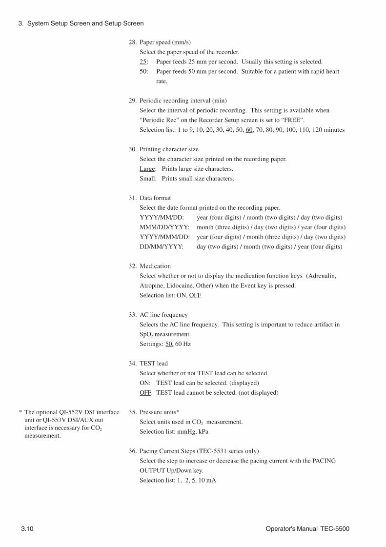
3. System Setup Screen and Setup Screen
3.10 Operator's Manual TEC-5500
28. Paper speed (mm/s)
Select the paper speed of the recorder.
25: Paper feeds 25 mm per second. Usually this setting is selected.
50: Paper feeds 50 mm per second. Suitable for a patient with rapid heart
rate.
29. Periodic recording interval (min)
Select the interval of periodic recording. This setting is available when
“Periodic Rec” on the Recorder Setup screen is set to “FREE”.
Selection list: 1 to 9, 10, 20, 30, 40, 50, 60, 70, 80, 90, 100, 110, 120 minutes
30. Printing character size
Select the character size printed on the recording paper.
Large: Prints large size characters.
Small: Prints small size characters.
31. Data format
Select the date format printed on the recording paper.
YYYY/MM/DD: year (four digits) / month (two digits) / day (two digits)
MMM/DD/YYYY: month (three digits) / day (two digits) / year (four digits)
YYYY/MMM/DD: year (four digits) / month (three digits) / day (two digits)
DD/MM/YYYY: day (two digits) / month (two digits) / year (four digits)
32. Medication
Select whether or not to display the medication function keys (Adrenalin,
Atropine, Lidocaine, Other) when the Event key is pressed.
Selection list: ON, OFF
33. AC line frequency
Selects the AC line frequency. This setting is important to reduce artifact in
SpO2 measurement.
Settings: 50, 60 Hz
34. TEST lead
Select whether or not TEST lead can be selected.
ON: TEST lead can be selected. (displayed)
OFF: TEST lead cannot be selected. (not displayed)
35. Pressure units*
Select units used in CO2 measurement.
Selection list: mmHg, kPa
36. Pacing Current Steps (TEC-5531 series only)
Select the step to increase or decrease the pacing current with the PACING
OUTPUT Up/Down key.
Selection list: 1, 2, 5, 10 mA
* The optional QI-552V DSI interfaceunit or QI-553V DSI/AUX outinterface is necessary for CO2
measurement.
3. System Setup Screen and Setup Screen
Operator's Manual TEC-5500 3.11
37. Pacing Power on Settings (TEC-5531 series only)
Select the pacing settings (pacing current and pacing rate) when the power is
turned on.
Default: Pacing settings are set to the default settings.
Latest: Pacing settings are set to the settings of the previous use.
39. Load Settings
Select “ON” to load the system setup settings and setup settings from the SD
card.
Selection list: OK, OFF
40. Save Settings
Select “OK” to save the system setup settings and setup settings in the SD
card.
Selection list: OK, OFF
41. Format Card
Select “OK” to format the SD card.
Selection list: OK, OFF
42. System initialize
Select “OK” to initialize the system setup settings and setup settings.
Selection list: OK, OFF
If “OK” is selected, a further message appears as below.
OK: Initialization starts.
Cancel: Cancels initialization.

3. System Setup Screen and Setup Screen
3.12 Operator's Manual TEC-5500
System Information
Report History
Recorder Check
Battery Test
HV Capacitor Test
Refer to Section 10 “Periodical Checks - Battery Test”.
Refer to Section 10 “Periodical Checks - HV Capacitor Test”.
Refer to Section 10 “Periodical Checks - Recorder Test”.
This item displays the system information.
1. On the System Setup-Menu screen, select “System Information” by pressing
the Item key and press the OK key. The system information is displayed on the
screen.
2. Press the Menu key to return to the System Setup - Menu screen.
Information for maintenance is printed.
1. On the System Setup - Menu screen, select “Report History” with the Item key
and press the OK”. The Report History screen opens.
2. To print an error history (error code)
1) Select “Instrument report” with the Item key
2) Press the Record key. The history of the error (error code), battery test and
HV capacitor test is recorded together. For the error code, refer to the
service manual.
To print the operation history since the selected date
1) Select “Year” with the Item key and select a year with the ↓ or ↑ key.
2) Select the “Month”, “Day”, “Hour” and “Minute” in the same way.
3) Press the Record key.
To cancel printing, press the Record key.
To return to the System Setup - Menu screen, press the Menu key.

3. System Setup Screen and Setup Screen
Operator's Manual TEC-5500 3.13
Use Voice File In the Use Voice File screen, you can play back the recorded sound and ECG
waveforms saved in the SD card.
1. On the System Setup-Menu screen, select “Use Voice File” by pressing the Item
and press the OK key. The Use Voice File screen is displayed.
2. Select the file with the ↓ or ↑ key and press the Playback key. The ECG
waveforms in the selected file are played back.
• To view the ECG waveforms beyond the border of the screen, press the ← or
→ key.
• To play back the sound, press the Playback key.
• To rewind the waveforms and sound, press the ← key
• To stop playing back, press the Stop key.
3. Press the Return key to return to the file selection list.
4. Press the Menu key to return to the System Setup - Menu screen.

3. System Setup Screen and Setup Screen
3.14 Operator's Manual TEC-5500
Setup Screen
Set the settings to fit your usage purpose.
NOTE• The changed settings are immediately applied to operation when they
are selected. If you want to return a setting to its previous value, set
the setting again.
• When the screen changes to any setup screen during recording,
recording automatically stops. Record again after exiting the setup
screen.
Setup Item List
Item Description
Sync by paddle lead Select whether or not to enable synchronized cardioversion with the PADDLE lead.
Paddle setup Heart rate alarm with paddle lead
Select whether or not to generate heart rate alarms when monitoring ECG with the PADDLE lead.
AC hum filter When set to “ON”, the hum filter automatically reduces AC interference from the ECG.
Time Constant Selects the time constant for ECG display in monitoring mode. Pacing Pulse Reject When set to “ON”, it allows correct heart rate counting when the patient
has an implanted pacemaker.
ECG setup
HR alarm Select the upper and lower limit of the heart rate alarm. Sens Select the pulse wave sensitivity SpO2 Sound When set to ON, the pitch of the sync sound changes according to SpO2
value PR alarm Select the upper and lower limit of the pulse rate alarm.
SpO2 setup
SpO2 alarm Select the upper and lower limit of the SpO2 alarm. Scale Select the scale of the CO2 waveform etCO2 alarm Select the upper and lower limit of the etCO2 alarm. RR alarm Select the upper and lower limit of the respiration rate alarm.
CO2 setup
APNEA alarm Select the upper limit of the APNEA alarm. Report Select the type of report recording. Trend Time Select the time length to be recorded in the Trend report recording. List Interval Select the measurement interval for Periodic List report recording. Report setup Delete Report? Select Yes to delete all report data saved in the instrument. When Yes is
selected, further confirmation keys appear. Press the key for “Delete” to delete all report data.
PeriodicRec Select the recording interval for the automatic periodic recording. Recorder setup RecWave Select the parameter(s) which is recorded in waveform recording, alarm
report recording, event recording and automatic recording. Year, Month, Day, Hour, Minute
Select the date and time. Date/Screen
2nd Wave Select the second waveform displayed on the trace 2. QRS Setup QRS Volume Select the QRS sync sound volume. QRS Sound Select the source of the QRS sync sound. VF/VT Alarm Select whether or not to detect VF/VT.
Alarm setup HR, PR, SpO2, etCO2, RR, APNEA
Select upper/lower limits for each parameter. (only upper limit for APNEA)
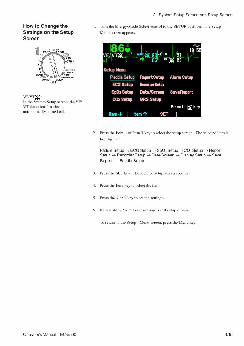
3. System Setup Screen and Setup Screen
Operator's Manual TEC-5500 3.15
How to Change theSettings on the SetupScreen
1. Turn the Energy/Mode Select control to the SETUP position. The Setup -
Menu screen appears.
2. Press the Item ↓ or Item ↑ key to select the setup screen. The selected item is
highlighted.
Paddle Setup → ECG Setup → SpO2 Setup → CO2 Setup → ReportSetup → Recorder Setup → Date/Screen → Display Setup → SaveReport → Paddle Setup
3. Press the SET key. The selected setup screen appears.
4. Press the Item key to select the item.
5. Press the ↓ or ↑ key to set the settings.
6. Repeat steps 2 to 5 to set settings on all setup screen.
To return to the Setup - Menu screen, press the Menu key.
VF/VT :In the System Setup screen, the VF/VT detection function isautomatically turned off.

3. System Setup Screen and Setup Screen
3.16 Operator's Manual TEC-5500
Date/Screen
Paddle Setup
ECG Setup
SpO2 Setup
CO2 Setup
Report Setup
Recorder Setup
Refer to Section 4 “Changing Paddle Settings”.
Refer to Section 6 “Changing ECG Settings”.
Refer to Section 6 “Changing SpO2 Settings”.
Refer to Section 6 “Changing CO2 Settings”.
Refer to Section 8 “Changing Report and Recorder Settings”.
Refer to Section 8 “Changing Report and Recorder Settings”.
On the Date/Screen screen, you can set the date and time and the waveform in
second trace.
Date and Time
Set the defibrillator date and time.
NOTEAfter performing the basic checks, make sure that the date and time
printed on the recording paper is correct. The date and time on the
recording paper are important parts of the medical record.
Setting range
Year: 1980 to 2079, Month: 1 to 12, Day: 1 to 31, Hour: 0 to 23, Minute: 0 to 59

3. System Setup Screen and Setup Screen
Operator's Manual TEC-5500 3.17
1. On the Date/Screen screen, select “Year”, “Month”, “Day”, “Hour”, or
“Minute” with the Item key.
2. Set the date and/or time with the ↓ or ↑ key.
3. Repeat steps 1 and 2 to set all parameters.
4. Press the Menu key to return to the Setup - Menu screen.
You cannot set seconds on this screen. For the most accurate time setting, look
at your local clock. Change the minute on the defibrillator and exit the Date/
Screen screen when the minute changes on your local clock. The second
count is set to 0 when you exit the Date/Screen screen after changing the
minute.
2nd Wave
Set the waveform in the second trace.
1. On the Date/Screen screen, select “2nd Wave” with the Item key.
2. Select the waveform displayed in the second trace with the ↓ or ↑ key.
3. Press the Menu key to return to the Setup - Menu screen.
Refer to Section 6 “Changing ECG Settings” and “Changing SpO2 Settings”
Refer to Section 7 “Setting Alarm”.Alarm Setup
QRS Setup
Setting Trace Acquired parameters
ECG ECG and SpO2 ECG and CO2 ECG, SpO2 and CO2
OFF First trace ECG ECG ECG ECG Second trace --- --- --- --- Bar graph None SpO2 CO2 SpO2 and CO2
Cascade First trace ECG ECG ECG ECG Second trace Cascaded ECG Cascaded ECG Cascaded ECG Cascaded ECG Bar graph None SpO2 CO2 SpO2 and CO2
SpO2 First trace ECG ECG ECG ECG Second trace --- SpO2 --- SpO2 Bar graph None --- CO2 CO2
CO2 First trace ECG ECG ECG ECG Second trace --- --- CO2 CO2 Bar graph None SpO2 --- SpO2
SpO2/CO2 First trace ECG ECG ECG ECG Second trace --- SpO2 CO2 SpO2 Bar graph None --- --- CO2
SpO2/CO2 First trace ECG ECG ECG ECG Second trace --- SpO2 CO2 CO2 Bar graph None --- --- SpO2

3. System Setup Screen and Setup Screen
3.18 Operator's Manual TEC-5500
Save Report The data of Alarm report recording, Defibrillation report recording, VF Analysis
report recording and Event report recording are saved in memory. These data can
be saved in a memery card (SD card). The waveform and its information are saved.
1. On the Setup Menu screen, select “Save Report” and press the SET key. The
Save Report screen appears.
The list of saved report data are displayed with the latest one at the top. The
selected report data is highlighted. The date includes date and time and report
type. Up to five report data are listed on one screen.
The “Insert SD CARD” message appears when a memory card is not inserted
into the card slot. When a memory card is already inserted into the card slot,
the “Wait, searching for data” message and the remaining free memory are
displayed.
2. Insert the memory card into the card slot.
The remaining free memory of the card is displayed on the screen. While the
defibrillator is checking the card, the “Wait, searching for data” message is
displayed.
When a report data on the screen has already been saved in the inserted
memory card, the file name of the report data appears beside the data.
• To select a report data you want to save, use the ↓ or ↑ key. When there is
more data than currently displayed on the screen, “ ” and “ ” marks
appear above and below the list.
• To print the selected (highlighted) report data, pressing the Record key.
• To display the preview waveform of a selected report data, press the Event
key.
• To scroll the waveform, press the ← or → key.
• To close the preview screen, press the Event key.

3. System Setup Screen and Setup Screen
Operator's Manual TEC-5500 3.19
2. Press the Save key. The highlighted data on the Save Report screen is saved in
the card and the file name is displayed. When a preview screen is displayed,
the data of the displayed waveform is saved. During saving, the “Saving don’t
power off” message is displayed.
To return to the Setup Menu screen, press the Menu key.
NOTE• Data which has already been saved in the inserted card cannot be
saved in the same card.
• When the memory card is full, the “Not enough free memory” message
appears. In this case, insert another memory card.
Preview screen

3. System Setup Screen and Setup Screen
3.20 Operator's Manual TEC-5500
This page is intentionally left blank.

Operator's Manual TEC-5500 4C.1
Section 4 Defibrillation,SynchronizedCardioversion and AED
General
About Defibrillation, Synchronized Cardioversion and AED ............................................ 4.0.1
Skin-Paddle Contact Impedance .................................................................................... 4.0.2
Using the Pediatric Electrode Plate ................................................................................ 4.0.3
Changing Paddle Settings .............................................................................................. 4.0.4
Turning Synchronized Cardioversion With PADDLE Lead On/Off ........................ 4.0.4
Turning Heart Rate Alarm with PADDLE Lead On/Off .......................................... 4.0.5
Using the ECG Waveforms from Another Monitor, Paddles or Disposable Pads for
Synchronized Cardioversion ........................................................................................... 4.0.6
ECG Input from Another Monitor .......................................................................... 4.0.6
ECG Input from External Paddles, Internal Paddles and Disposable Pads .......... 4.0.8
Defibrillation
Defibrillation Screen ........................................................................................................ 4.1.1
Defibrillation with External Paddles ................................................................................. 4.1.2
Important Safety Information ................................................................................ 4.1.2
Procedure ............................................................................................................. 4.1.3
Defibrillation with Disposable Pads ................................................................................. 4.1.8
Important Safety Information ................................................................................ 4.1.8
Procedure ............................................................................................................. 4.1.9
Defibrillation with Internal Paddles ................................................................................ 4.1.15
Important Safety Information .............................................................................. 4.1.15
Procedure ........................................................................................................... 4.1.16
Synchronized Cardioversion
Synchronized Cardioversion Screen .............................................................................. 4.2.1
Synchronized Cardioversion with External Paddles ....................................................... 4.2.2
Important Safety Information ................................................................................ 4.2.2
Procedure ............................................................................................................. 4.2.3
Synchronized Cardioversion with Disposable Pads........................................................ 4.2.9
Important Safety Information ...................................................................................4.2.9
Procedure............................................................................................................. 4.2.11
Synchronized Cardioversion with Internal Paddles .......................................................... 4.2.17
Important Safety Information ................................................................................. 4.2.17
Procedure............................................................................................................. 4.2.18

4C.2 Operator's Manual TEC-5500
AED
AED Screen .................................................................................................................... 4.3.1
Important Safety Information........................................................................................... 4.3.2
AED Flowchart ................................................................................................................ 4.3.4
Preparation for AED Mode .................................................................................... 4.3.5
AED Procedure ............................................................................................................... 4.3.6
When Nonshockable Rhythm Is Detected In AED Analysis ................................ 4.3.15

Operator's Manual TEC-5500 4.0C.1
General
About Defibrillation, Synchronized Cardioversion and AED ..............................................4.0.1
Skin-Paddle Contact Impedance ......................................................................................4.0.2
Using the Pediatric Electrode Plate ..................................................................................4.0.3
Changing Paddle Settings .................................................................................................4.0.4
Turning Synchronized Cardioversion With PADDLE Lead On/Off ............................4.0.4
Turning Heart Rate Alarm with PADDLE Lead On/Off .............................................4.0.5
Using the ECG Waveforms from Another Monitor, Paddles or Disposable Pads for
Synchronized Cardioversion .............................................................................................4.0.6
ECG Input from Another Monitor ............................................................................4.0.6
ECG Input from External Paddles, Internal Paddles and Disposable Pads .............4.0.8

4.0C.2 Operator's Manual TEC-5500
This page is intentionally left blank.

4. DEFIBRILLATION, SYNCHRONIZED CARDIOVERSION and AED
Operator's Manual TEC-5500 4.0.1
About Defibrillation, Synchronized Cardioversion and AED
This section explains the procedures to perform defibrillation, synchronized
cardioversion and AED. You can use external paddles, internal paddles and
disposable pads for defibrillation and synchronized cardioversion. You can use
only disposable pads for AED.
WARNINGThe defibrillator generates high voltage. The defibrillator must only
be operated by trained and qualified medical personnel.
NOTEEven if a defibrillation or cardioversion is performed on a patient
appropriately, the patient may get skin burn.
• Defibrillation
Used for terminating fatal arrhythmias, such as ventricular fibrillation and
pulseless ventricular tachycardia. Energy is discharged asynchronously.
• Synchronized cardioversion
Used for eliminating atrial fibrillation and atrial flutter. The defibrillator detects
the patient’s ECG and energy is discharged at an appropriate timing.
• AED
The defibrillator analyzes the patient’s ECG. When the defibrillator detects a
shockable rhythm, it automatically starts charging the selected energy.
Discharging is not performed automatically.

4. DEFIBRILLATION, SYNCHRONIZED CARDIOVERSION and AED
4.0.2 Operator's Manual TEC-5500
Skin-Paddle Contact Impedance
To perform effective defibrillation or cardioversion, it is important to make the
skin-paddle contact impedance as low as possible. Recommended applied pressure
on a paddle is about 100 N (10kg, 22lb.) per paddle.
For this defibrillator, the CONTACT lamp on the STERNUM paddle indicates skin-
paddle contact impedance.
0 to 100Ω: green lamp lights
100 to 200Ω: yellow lamp lights
more than 200Ω: orange lamp lights
Place the paddles so that the green lamp lights.
If the green lamp does not light, do the following.
• Apply the contact gel on the paddles uniformly.
• Clip hair on the skin where paddles are placed.
• Press the paddles against the patient and gradually increase the pressure until the
green lamp lights.
For a patient with chest hair, old patient with skin cornification (hardening) or thin
patient, the green lamp does not light. You can discharge energy when the lamp is
yellow or orange.
WARNINGIn Case of Poor Contact
If the yellow or orange lamp lights, the defibrillator may cause serious
electric burn on the patient’s skin and poor energy discharge to the
patient. In case of an emergency, medical personnel should decide
whether to execute discharge immediately, regardless of the CONTACT
lamp display, or take action to make good contact before discharge.

4. DEFIBRILLATION, SYNCHRONIZED CARDIOVERSION and AED
Operator's Manual TEC-5500 4.0.3
Using the Pediatric Electrode Plate
The pediatric electrode plate is underneath the adult electrode plate of the external
paddle. You can also attach the optional pediatric electrode assy 44 mm dia. on the
pediatric electrode plate of the external paddle.
WARNINGPay careful attention to the selected energy when using the pediatric
electrode plates. Applying high energy with the pediatric electrode
plates can cause skin burn because the electrode plates are small.
The current density on the pediatric electrode plates is higher than the current
density on the adult electrode plates because the pediatric electrode plates are
smaller* than the adult electrode plates. This increases the possibility of electrical
burn on the electrode plate placement area. The minimum effective energy should
be set.
* The pediatric electrode plates underneath the adult electrode plates are about 1/3
the surface area of the adult electrode plates. The pediatric electrodes assy 44
mm dia. are about 1/5 the surface area of the adult electrode plates.
To remove the adult electrode plate:
1. Turn the Energy/Mode select control to the OFF position.
NOTEWhile the “Shutdown NOW” message is displayed on the screen, do not
disconnect the power cord from the defibrillator or AC outlet and do not
remove the battery pack from the defibrillator. Otherwise, the internal
data may be damaged.
2. Press the tab of the adult electrode plate to unlock the adult electrode plate.
3. Slide the adult electrode plate forward and off.

4. DEFIBRILLATION, SYNCHRONIZED CARDIOVERSION and AED
4.0.4 Operator's Manual TEC-5500
Changing Paddle Settings
Turning SynchronizedCardioversion WithPADDLE Lead On/Off
Select whether or not to allow synchronized cardioversion with the PADDLE lead.
ON: Synchronized cardioversion with PADDLE lead is available.
OFF Synchronized cardioversion with PADDLE lead is not available (Default
setting: OFF).
WARNING• Use the ECG monitoring electrodes (disposable electrodes) to monitor
the ECG waveforms. Stable ECG cannot be acquired with the PADDLE
lead because it is difficult to hold the paddles stable. Also, ECG
waveform is unstable after discharge because polarization voltage is
very high.
• Do not perform synchronized cardioversion with the PADDLE lead
unless it is absolutely necessary. In synchronized cardioversion with
the PADDLE lead, noise may be misrecognized as QRS and
discharge might not synchronize with the patient’s QRS.
NOTEFirmly connect the disposable pads to the pad adaptor until the
connector of the disposable pads clicks. If the pads are not attached
firmly or the pads are not connected to the pad adaptor, noise appears
on the ECG waveform.
1. On the Paddle Setup screen, select “Sync by paddle lead” with the Item key.
VF/VT :In the System Setup screen, the VF/VT detection function isautomatically turned off.
2. Select “ON” or “OFF” with the ↓ or ↑ key.

4. DEFIBRILLATION, SYNCHRONIZED CARDIOVERSION and AED
Operator's Manual TEC-5500 4.0.5
Turning Heart Rate Alarmwith PADDLE Lead On/Off
Select whether or not to generate heart rate alarms when monitoring ECG with the
PADDLE lead.
ON: Heart rate alarms are generated when monitoring ECG with the PADDLE
lead. For long term monitoring using disposable pads, set this to ON.
OFF : Heart rate alarms are not generated when monitoring ECG with the PADDLE
lead. When you use external paddles or internal paddles, set this to OFF
(Default setting: OFF).
1. On the Paddle Setup screen, select “Heart rate alarm with paddle lead” with the
Item key.
2. Select ON or OFF with the ↓ or ↑ key.

4. DEFIBRILLATION, SYNCHRONIZED CARDIOVERSION and AED
4.0.6 Operator's Manual TEC-5500
Using the ECG Waveforms from Another Monitor, Paddles or
Disposable Pads for Synchronized Cardioversion
You can acquire ECG waveforms for synchronized cardioversion by the following
three ways.
• From the ECG connection cable and ECG disposable electrode.
• From another monitor
• From external paddles, internal paddles or disposable pads
When the patient is already connected to a monitor, it may be possible to use the
ECG signal from the monitor, but, this is not recommended.
WARNINGIf you use the ECG signal from the monitor, before cardioversion,
check that the defibrillator discharge occurs within 60 ms of the peak
of the ECG’s R wave with a delivery checker. If this condition is not
met, the cardioversion may be ineffective or may cause ventricular
fibrillation.
CAUTIONThe external instrument must comply with the CISPR 11 Second Edition
1990-09, Group 1 and Class B standard.
NOTEWhen receiving the ECG signal from a bedside monitor, select lead II or
I on the bedside monitor.
To use ECG signal from another monitor as the synchronizing signal of
synchronized cardioversion
• Connect the defibrillator to the other instrument with the optional JC-761V
External ECG cable.
• Select “AUX” for ECG lead.
ECG Input from AnotherMonitor

4. DEFIBRILLATION, SYNCHRONIZED CARDIOVERSION and AED
Operator's Manual TEC-5500 4.0.7
Use the following procedure to check whether or not synchronized cardioversion
can be performed with the ECG signal from another instrument.
1. Connect the defibrillator to the other instrument with the optional JC-761V
External ECG cable.
2. Turn the power of the other instrument on.
3. Turn the Energy/Mode Select control to the DISARM position.
4. Select “AUX” with the ECG lead key.
5. Connect an delivery checker to the other instrument and turn the delivery
checker on to generate ECG signals.
6. Turn the Energy/Mode Select control to 50 J.
7. Press the SYNC button on the front panel.
8. Check that the “ ” mark appears on the rising slope of every QRS wave.
9. Leaving the paddles on the holders of the delivery checker, press the CHARGE
button on the APEX paddle to start charging. During charging, there is a
beeping sound, a “CHARGING” message appears, and the CHARGE lamps on
the APEX paddle.
When charging is completed, there is a continuous buzzing sound, the
“CHARGED” message appears, and the CHARGE lamps light.
JC-761V External ECG cable
Connects to output signal line
Connects to GND line
red
black
10. Simultaneously press and hold both DISCHARGE buttons on the external
paddles.
4. DEFIBRILLATION, SYNCHRONIZED CARDIOVERSION and AED
4.0.8 Operator's Manual TEC-5500
ECG Input from ExternalPaddles, Internal Paddlesand Disposable Pads
The defibrillator can perform synchronized cardioversion with the PADDLE lead.
To use ECG from external paddles, internal paddles or disposable pads for
synchronizing signal of synchronized cardioversion,
• Set the “Sync by paddle lead” on the Paddle Setup screen to ON
• Select “PADDLE” for ECG lead.
WARNINGDo not perform synchronized cardioversion with the PADDLE lead
unless it is absolutely necessary. In synchronized cardioversion with
the PADDLE lead, noise may be misrecognized as QRS and discharge
might not synchronize with the patient’s QRS.
NOTE• Place the paddles on the patient so that the whole waveform is
displayed on the screen and the T waveform is not much higher than
the QRS waveform. Otherwise, QRS cannot be recognized correctly.
• If the defibrillator miscounts the narrow width QRS, set “Pacing Pulse
Reject” to OFF on the ECG Setup screen and confirm that QRS is
correctly recognized.

Operator's Manual TEC-5500 4.1C.1
Defibrillation
Defibrillation Screen .........................................................................................................4.1.1
Defibrillation with External Paddles ...................................................................................4.1.2
Important Safety Information .................................................................................4.1.2
Procedure...............................................................................................................4.1.3
Defibrillation with Disposable Pads ...................................................................................4.1.8
Important Safety Information .................................................................................4.1.8
Procedure...............................................................................................................4.1.9
Defibrillation with Internal Paddles .................................................................................. 4.1.15
Important Safety Information ............................................................................... 4.1.15
Procedure............................................................................................................. 4.1.16

4.1C.2 Operator's Manual TEC-5500
This page is intentionally left blank.
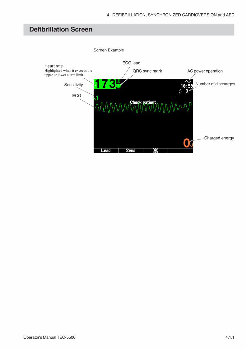
4. DEFIBRILLATION, SYNCHRONIZED CARDIOVERSION and AED
Operator's Manual TEC-5500 4.1.1
Defibrillation Screen
Screen Example
Heart rateHighlighted when it exceeds theupper or lower alarm limit.
ECG lead
QRS sync mark
Sensitivity
ECG
AC power operation
Charged energy
Number of discharges

4. DEFIBRILLATION, SYNCHRONIZED CARDIOVERSION and AED
4.1.2 Operator's Manual TEC-5500
Defibrillation with External Paddles
Important SafetyInformation WARNING
• Before defibrillation, make sure that no one is in contact with either
the patient or any metal part of any equipment or cables which
supports or is connected to the patient. Failure to follow this
warning causes serious electrical shock or injury.
• Before defibrillation, remove from the patient all electrodes, probes
and transducers from a connector that do not have a “ ” or “ ”
mark. Otherwise, the operator may receive electrical shock and the
connected instrument may be damaged.
• Before defibrillation, remove everything (electrodes, patches, etc.)
from the patient’s chest. When the defibrillator paddle directly
contacts these materials, the discharged energy may cause skin burn
to the patient.
• Before defibrillation, check that the cords and cables of the
electrodes, probes and transducers attached to the patient are
properly connected to a connector that has a “ ” or “ ” mark.
Touching the metal parts of the disconnected cords and cables may
cause electrical shock or injury by discharged energy.
• When using an ESU, use this defibrillator only in the MONITOR mode
and use the ECG electrodes for monitoring. Do not monitor ECG with
disposable pads, external paddles or internal paddles. If ECG is
monitored with pads or paddles, high frequency energy from the
ESU causes abnormal current to flow in the patient and unexpected
discharge. This may damage the defibrillator.
• Use the ECG monitoring electrodes (disposable electrodes) to
monitor the ECG waveforms. Stable ECG cannot be acquired with
the PADDLE lead because it is difficult to hold the paddles stable.
ECG acquired from external paddles, internal paddles or disposable
pads is unstable after discharge because of high polarization
voltage.
• Do not perform defibrillation in a wet place. Before defibrillation,
move the patient and defibrillator to a dry place. Otherwise the
operator may get electrical shock.
• The defibrillator must only be operated by trained and qualified
medical personnel.
NOTE• Select the appropriate energy and appropriate size of the external
paddles according to the patient. Only use the paddles specified by
Nihon Kohden.
• Defibrillation is not available when any setup screen or system setup
screen is displayed. Before using the defibrillator, confirm and set
the necessary settings on the Setup screen and System Setup -
Configuration screen.

4. DEFIBRILLATION, SYNCHRONIZED CARDIOVERSION and AED
Operator's Manual TEC-5500 4.1.3
Procedure1. Check that the external paddles are connected to the defibrillator.
2. Turn the Energy/Mode Select control to the DISARM position to turn the
power on. Confirm that there is no error message on the screen. For error
messages, refer to Section 9. When operating with AC power, confirm that the
AC lamp is on.
3. Confirm that the ECG lead is set to PADDLE. If another lead is selected, select
PADDLE with the ECG lead key.
4. Confirm that the SYNC lamp is not lit. If this lamp is lit, press the SYNC
button on the front panel to turn it off.
5. Prepare the paddles
1) Remove the external paddles from their holders by grasping the handles
and lifting straight up.
2) Apply contact gel to the electrode plate surface of each paddle.
3) Gently rub the electrode plate surfaces together to evenly spread the gel.
WARNING• Apply contact gel only to the electrode plates of the external
paddles. Otherwise, it may cause electrical shock to the operator.
• Do not apply contact gel by hand. Failure to follow this warning may
cause serious electrical burn, shock, or other injury.
• Do not hold the paddle handles if your hands are wet or have
contact gel on them. This may cause electrical shock to the
operator.
• To avoid skin burn on the patient and poor energy discharge to the
heart, apply contact gel to the electrode plates of the external
paddles.
6. Select the energy level
Turn the Energy/Mode Select control to the desired energy position.

4. DEFIBRILLATION, SYNCHRONIZED CARDIOVERSION and AED
4.1.4 Operator's Manual TEC-5500
APEX
STERNUM
7. Place the paddles on the patient
WARNINGDo not touch the electrode plate or edge of the paddle. Failure to
follow this warning may cause serious electrical burn, shock, or other
injury.
CAUTIONIf the patient’s body is wet, thoroughly wipe the moisture off the skin
so that the paddles do not short to each other.
Position
1) Place the left (STERNUM) paddle on the right side of sternum and below
the clavicle.
2) Place the right (APEX) paddle on the level of fifth intercostal space and
midaxillary line. When using the paddle lead, keep the paddles steady.
NOTEDo not lean against the paddles when pressing them on the patient. A
paddle may slip and cause injury.
8. Check the ECG waveform
Confirm that the patient’s ECG has a shockable rhythm, such as ventricular
fibrillation or pulseless ventricular tachycardia.
If the patient’s ECG requires synchronized cardioversion, follow the procedure
in “Synchronized Cardioversion” in this section.

4. DEFIBRILLATION, SYNCHRONIZED CARDIOVERSION and AED
Operator's Manual TEC-5500 4.1.5
9. Charge the energy
When it is verified that the patient needs defibrillation, press the CHARGE
button on the APEX paddle or CHARGE/AED button on the front panel to start
charging.
WARNING• When charging or discharging, do not touch anything other than the
handles. If any other part of the defibrillator is touched during
charging or discharging, the operator receives an electrical shock.
• Do not move the defibrillator when any charged energy remains in
the defibrillator. If the defibrillator receives any impact, such as
from falling, it discharges energy that can cause electrical shock.
During charging, there is a beeping sound, the “CHARGING” message appears
on the screen, and the CHARGE lamp blinks.
When charging is completed, there is a continuous buzzing sound, the
“CHARGED” message appears on the screen, and the CHARGE lamp lights.
To change the energy level after charging is completed
Turn the Energy/Mode Select control to the desired energy position. The
defibrillator starts adjusting the energy one second after the new energy is
selected.
When defibrillation becomes unnecessary after charging is completed
Turn the Energy/Mode Select control to the DISARM position or OFF position.
The defibrillator internally discharges charged energy within 20 seconds.
The defibrillator automatically internally discharges charged energy when the
charge holding time passes. This time is selected on the System Setup -
Configuration screen.
10. Check the skin-paddle contact impedance
The skin-paddle contact impedance is indicated by the CONTACT lamp on the
STERNUM external paddle. Press the paddles against the paddle placement
area so that the green lamp lights. Refer to “Skin-Paddle Contact Impedance”
in this section.
Bad example
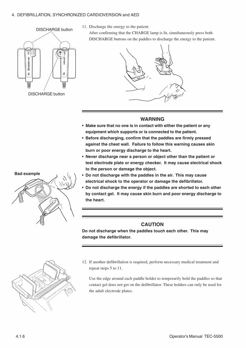
4. DEFIBRILLATION, SYNCHRONIZED CARDIOVERSION and AED
4.1.6 Operator's Manual TEC-5500
Bad example
11. Discharge the energy to the patient
After confirming that the CHARGE lamp is lit, simultaneously press both
DISCHARGE buttons on the paddles to discharge the energy to the patient.
WARNING• Make sure that no one is in contact with either the patient or any
equipment which supports or is connected to the patient.
• Before discharging, confirm that the paddles are firmly pressed
against the chest wall. Failure to follow this warning causes skin
burn or poor energy discharge to the heart.
• Never discharge near a person or object other than the patient or
test electrode plate or energy checker. It may cause electrical shock
to the person or damage the object.
• Do not discharge with the paddles in the air. This may cause
electrical shock to the operator or damage the defibrillator.
• Do not discharge the energy if the paddles are shorted to each other
by contact gel. It may cause skin burn and poor energy discharge to
the heart.
CAUTIONDo not discharge when the paddles touch each other. This may
damage the defibrillator.
12. If another defibrillation is required, perform necessary medical treatment and
repeat steps 5 to 11.
Use the edge around each paddle holder to temporarily hold the paddles so that
contact gel does not get on the defibrillator. These holders can only be used for
the adult electrode plates.
DISCHARGE button
DISCHARGE button

4. DEFIBRILLATION, SYNCHRONIZED CARDIOVERSION and AED
Operator's Manual TEC-5500 4.1.7
13. Turn the power off
Turn the Energy/Mode Select control to the OFF position to turn the
defibrillator power off.
NOTEWhile the “Shutdown NOW” message is displayed on the screen, do not
disconnect the power cord from the defibrillator or AC outlet and do not
remove the battery pack from the defibrillator. Otherwise, the internal
data may be damaged.
Thoroughly wipe off the contact gel from the external paddles and defibrillator.
Refer to “Cleaning, Disinfecting and Sterilization” in Section 10.
Put the external paddles on the paddle holders by pressing the paddles onto the
holders.

4. DEFIBRILLATION, SYNCHRONIZED CARDIOVERSION and AED
4.1.8 Operator's Manual TEC-5500
Defibrillation with Disposable Pads
Important SafetyInformation WARNING
• Before defibrillation, make sure that no one is in contact with either
the patient or any metal part of any equipment or cables which
supports or is connected to the patient. Failure to follow this
warning causes serious electrical shock or injury.
• Before defibrillation, remove from the patient all electrodes, probes
and transducers from a connector that do not have a “ ” or “ ”
mark. Otherwise, the operator may receive electrical shock and the
connected instrument may be damaged.
• Before defibrillation, remove everything (electrodes, patches, etc.)
from the patient’s chest. When the defibrillator paddle directly
contacts these materials, the discharged energy may cause skin burn
to the patient.
• Before defibrillation, check that the cords and cables of the
electrodes, probes and transducers attached to the patient are
properly connected to a connector that has a “ ” or “ ” mark.
Touching the metal parts of the disconnected cords and cables may
cause electrical shock or injury by discharged energy.
• When using an ESU, use this defibrillator only in the MONITOR mode
and use the ECG electrodes for monitoring. Do not monitor ECG with
disposable pads, external paddles or internal paddles. If ECG is
monitored with pads or paddles, high frequency energy from the
ESU causes abnormal current to flow in the patient and unexpected
discharge. This may damage the defibrillator.
• Use the ECG monitoring electrodes (disposable electrodes) to
monitor the ECG waveforms. Stable ECG cannot be acquired with
the PADDLE lead because it is difficult to hold the paddles stable.
ECG acquired from external paddles, internal paddles or disposable
pads is unstable after discharge because of high polarization
voltage.
• The defibrillator must only be operated by trained and qualified
medical personnel.
• Failure to follow the warnings below may cause skin burn or
insufficient energy discharge and insufficient pacing current to the
heart.
- Do not reuse disposable pads.
- If the pad package is torn, dispose of the pads and do not use
them.
- Do not use the pads if they are past the expiration date on the
package.
- Use the disposable pads as soon as possible after opening the
package.
- Do not use the disposable pads if the gel has become dry or if the
gel has become abnormal (the gel has become liquid or is coming

4. DEFIBRILLATION, SYNCHRONIZED CARDIOVERSION and AED
Operator's Manual TEC-5500 4.1.9
Procedure
off the edges of the pad, etc).
- Do not use the disposable pads if the gel is dark brown or dark
brown gel is on the protective sheet.
• If any pad or connector gets wet, replace it with a new one. If a wet
pad or connector is used, it may cause electrical shock.
• Do not perform defibrillation in a wet place. Before defibrillation,
move the patient and defibrillator to a dry place. Otherwise the
operator may get electrical shock.
CAUTION• When using the disposable pads for long term ECG monitoring,
replace them every 24 hours. Failure to follow this instruction may
cause insufficient pacing current and insufficient energy discharge to
the heart.
• Do not attach a disposable pad over another pad. It may cause skin
burn on the patient.
• Do not put heavy objects on the disposable pads or bend the pads. If
the pads get damaged or deteriorated, it may cause skin burn on the
patient.
NOTE• Follow all disposable pad labeling instructions.
• Always prepare the second set of disposable pads before
defibrillation. Use the second set of disposable pads if the gel of the
first set of disposable pads is dry, deteriorated or changes color.
• Before attaching the disposable pads to the patient, clean the skin
where the pads will be attached. If the skin is moist, use a cotton
swab to dry it.
• Only use the pads specified by Nihon Kohden.
• Defibrillation is not available when any Setup screen or System Setup
screen is displayed. Before using the defibrillator, confirm and set the
necessary settings on the Setup screen and System Setup -
Configuration screen.
1. Connect the pad adaptor to the defibrillator.
1) Press the paddle release knob of the paddle connector on the front panel
and remove the external paddles from the paddle connector..

4. DEFIBRILLATION, SYNCHRONIZED CARDIOVERSION and AED
4.1.10 Operator's Manual TEC-5500
CAUTIONWhen connecting the pad adapter to the paddle connector, do not
bend or damage the connector pin. Energy cannot be discharged to
the pads.
2. Turn the Energy/Mode Select control to the DISARM position to turn the
power on. Confirm that there is no error message on the screen. For error
messages, refer to Section 9. When operating with AC power, confirm that the
AC lamp is on.
3. Confirm that the ECG lead is set to PADDLE. If another lead is selected, select
PADDLE with the ECG lead key.
4. Confirm that the SYNC lamp is not lit. If this lamp is lit, press the SYNC
button on the front panel to turn it off.
5. Prepare the disposable pads.
1) To allow firm pad contact with the skin, clean the patient’s chest to remove
oil and dirt, and thoroughly dry the skin. Clip excessive hair, if necessary.
NOTEDo not apply any gel or paste when using disposable pads.
2) Take the disposable pads out of the package and carefully remove the
protective liner from one pad at a time.
2) Connect the pad adaptor to the paddle connector until it clicks.
3) Attach the pads to the patient’s body, one at a time.

4. DEFIBRILLATION, SYNCHRONIZED CARDIOVERSION and AED
Operator's Manual TEC-5500 4.1.11
Apex-Posterior placement
Apex-Anterior placement
RA: Right side of sternum and below the clavicle
LL: On the level of fifth intercostal space and midaxillary line
RA: Between right scapula and spine
LL: On the level of fifth intercostal space and midaxillary line
WARNING• Do not attach pads on the papilla, electrodes or medicine on the
patient’s body. Failure to follow this warning causes serious skin
burn.
• Fit the pad closely to the body surface so that current flows uniformly
through the pad. Failure to follow this warning causes serious skin
burn or insufficient energy discharge to the heart.
CAUTIONIf the patient’s body is wet, thoroughly wipe the moisture off the skin
so that the paddles do not short to each other.
NOTEWhen the skin-pad contact is poor, it causes high electrode impedance
and energy cannot be charged.

4. DEFIBRILLATION, SYNCHRONIZED CARDIOVERSION and AED
4.1.12 Operator's Manual TEC-5500
NOTE• Firmly connect the disposable pads to the pad adaptor until the
connector of the disposable pads clicks.
• When the “Change disposable pads” message appears, the pads may
be faulty. Replace them with new ones. If the message still appears,
stop using the defibrillator and use a different defibrillator.
6. Check the ECG waveform
Confirm that the patient’s ECG has a shockable rhythm, such as ventricular
fibrillation or pulseless ventricular tachycardia.
If the patient’s ECG requires synchronized cardioversion, follow the procedure
in “Synchronized Cardioversion” in this section.
7. Select the energy level
Turn the Energy/Mode Select control to the desired energy position.
8. Charge the energy
When it is verified that the patient needs defibrillation, press the CHARGE/
AED button on the front panel to start charging.
WARNING• During charging or discharging, do not touch the pads or connectors.
Failure to follow this warning causes electrical shock to the operator.
• Do not move the defibrillator when any charged energy remains in
the defibrillator. If the defibrillator receives any impact, such as
from falling, it discharges energy that can cause electrical shock.
NOTE• If the CHARGE/AED button is pressed when a disposable pad is
detached from the patient, charging does not start.
• If a disposable pad is detached during or after charging, the
defibrillator automatically discharges energy internally within 20
seconds.
4) Connect the disposable pads to the pad adaptor.

4. DEFIBRILLATION, SYNCHRONIZED CARDIOVERSION and AED
Operator's Manual TEC-5500 4.1.13
When charging is completed, there is a continuous buzzing sound, the
“CHARGED” message appears on the screen, and the DISCHARGE lamp
blinks.
During charging, there is a beeping sound, the “CHARGING” message appears
on the screen.
To change the energy level after charging is completed
Turn the Energy/Mode Select control to the desired energy position. The
defibrillator starts adjusting the energy one second after the new energy is
selected.
When defibrillation becomes unnecessary after charging is completed
Turn the Energy/Mode Select control to the DISARM position or OFF position.
The defibrillator internally discharges charged energy within 20 seconds.
The defibrillator automatically internally discharges charged energy when the
charge holding time has passed. This time is selected on the System Setup -
Configuration screen.
9. Discharge the energy to the patient
After confirming that the DISCHARGE lamp blinks, press the DISCHARGE
button on the front panel to discharge the energy to the patient.
WARNING• Before discharging, confirm that the pads are firmly applied to the
chest wall. Failure to follow this warning causes skin burn or poor
energy discharge to the heart.
• Do not discharge if the pads overlap each other or are shorted to
each other by anything conductive such as contact gel. This may
cause skin burn and poor energy discharge to the heart.
• Make sure that no one is in contact with either the patient or any
equipment which supports or is connected to the patient.
10. If another defibrillation is required, perform necessary medical treatment and
repeat steps 7 to 9.

4. DEFIBRILLATION, SYNCHRONIZED CARDIOVERSION and AED
4.1.14 Operator's Manual TEC-5500
11. Turn the power off
Turn the Energy/Mode Select control to the OFF position.
NOTEWhile the “Shutdown NOW” message is displayed on the screen, do not
disconnect the power cord from the defibrillator or AC outlet and do not
remove the battery pack from the defibrillator. Otherwise, the internal
data may be damaged.
Press the paddle release knob of the paddle connector to the right and remove
the pad adaptor from the paddle connector. Hold the connector part to
disconnect the pad adaptor. Otherwise the connector gets damaged and the
cable breaks.
Dispose of the disposable pads. Refer to “Cleaning, Disinfecting and
Sterilization” in Section 10.

4. DEFIBRILLATION, SYNCHRONIZED CARDIOVERSION and AED
Operator's Manual TEC-5500 4.1.15
Defibrillation with Internal Paddles
Important SafetyInformation
By directly applying the internal paddles to the heart, defibrillation during open chest
operation is available.
WARNING• Before defibrillation, make sure that no one is in contact with either the
patient or any metal part of any equipment or cables which supports or is
connected to the patient. Failure to follow this warning causes serious
electrical shock or injury.
• Before defibrillation, remove from the patient all electrodes, probes and
transducers from a connector that do not have a “ ” or “ ” mark.
Otherwise, the operator may receive electrical shock and the connected
instrument may be damaged.
• Before defibrillation, remove everything (electrodes, patches, etc.) from the
patient’s chest. When the defibrillator paddle directly contacts these
materials, the discharged energy may cause skin burn to the patient.
• Before defibrillation, check that the cords and cables of the electrodes,
probes and transducers attached to the patient are properly connected to a
connector that has a “ ” or “ ” mark. Touching the metal parts of the
disconnected cords and cables may cause electrical shock or injury by
discharged energy.
• When using an ESU, use this defibrillator only in the MONITOR mode and
use the ECG electrodes for monitoring. Do not monitor ECG with disposable
pads, external paddles or internal paddles. If ECG is monitored with pads
or paddles, high frequency energy from the ESU causes abnormal current to
flow in the patient and unexpected discharge. This may damage the
defibrillator.
• Use the ECG monitoring electrodes (disposable electrodes) to monitor the
ECG waveforms. Stable ECG cannot be acquired with the PADDLE lead
because it is difficult to hold the paddles stable. ECG acquired from
external paddles, internal paddles or disposable pads is unstable after
discharge because of high polarization voltage.
• The defibrillator must only be operated by trained and qualified medical
personnel.
• Sterilize the internal paddles before use. Failure to sterilize the paddles
may cause serious infection.
• Pay careful attention to the energy selection when using internal paddles.
Applying high energy to the heart may cause cardiac muscle necrosis. Low
energy is recommended.
• Do not perform defibrillation in a wet place. Before defibrillation, move the
patient and defibrillator to a dry place. Otherwise the operator may get
electrical shock.

4. DEFIBRILLATION, SYNCHRONIZED CARDIOVERSION and AED
4.1.16 Operator's Manual TEC-5500
Procedure It is reported that the cardiac muscle may necrose if high energy is repeatedly
applied to the heart with internal paddles. Refer to “Reference” in Section 11.
1. Connect the internal paddles to the defibrillator.
1) Press the paddle release knob of the paddle connector to the right and
remove the external paddles from the paddle connector.
CAUTIONDo not twist the internal paddle while holding the electrode or give
strong impact to the paddle. It damages the electrode.
NOTE• Select the appropriate energy and appropriate size of the internal
paddles according to the patient. Only use the paddles specified by
Nihon Kohden.
• Defibrillation is not available when any Setup screen or System
Setup screen is displayed. Before using the defibrillator, confirm
and set the necessary settings on the Setup screen and System
Setup - Configuration screen.
2) Connect the internal paddles to the paddle connector until it clicks.
CAUTIONDo not bend or damage the connector pins of the paddle connector.
Energy cannot be fully discharged if pins are bent or damaged.

4. DEFIBRILLATION, SYNCHRONIZED CARDIOVERSION and AED
Operator's Manual TEC-5500 4.1.17
When the internal paddles are used, 50 J or below can be selected. If above 50
J is selected, the “Set energy to 50 J or less” message appears on the screen and
the selected energy cannot be charged.
7. Charge the energy
When it is verified that the patient needs defibrillation, press the CHARGE/
AED button on the front panel to start charging.
WARNING• During charging and discharging, grip the internal paddles between
the guard at the top of the handle and the cable. If you grip the
handle between the electrode and the guard, you may get an
electrical shock.
• Do not move the defibrillator when any charged energy remains in
the defibrillator. If the defibrillator receives any impact, such as
from falling, it discharges energy that can cause electrical shock.
2. Turn the Energy/Mode Select control to the DISARM position to turn the
power on. Confirm that there is no error message on the screen. For error
messages, refer to Section 9. When operating with AC power, confirm that the
AC lamp is on.
3. Confirm that the SYNC lamp is not lit. If this lamp is lit, press the SYNC
button on the front panel to turn it off.
4. Position the internal paddles
Position the sterilized internal paddles against the right and the left atria of the
heart.
NOTE• It is not necessary to consider the polarities of the internal paddle
electrodes.
• For better contact between the internal paddles and heart, place
sterilized gauze moistened with physiological saline solution
between each internal paddle and the heart.
5. Check the ECG waveform
Confirm that the patient’s ECG has a shockable rhythm, such as ventricular
fibrillation or pulseless ventricular tachycardia.
If the patient’s ECG requires synchronized cardioversion, follow the procedure
in “Synchronized Cardioversion” in this section.
6. Select the energy level
Turn the Energy/Mode Select control to the desired energy position.
guard

4. DEFIBRILLATION, SYNCHRONIZED CARDIOVERSION and AED
4.1.18 Operator's Manual TEC-5500
To change the energy level after charging is completed
Turn the Energy/Mode Select control to the desired energy position. The
defibrillator starts adjusting the energy one second after the new energy is
selected.
NOTEIf above 50 J is selected, the defibrillator immediately discharges energy
internally.
When defibrillation becomes unnecessary after charging is completed
Turn the Energy/Mode Select control to the DISARM position or OFF position.
The defibrillator internally discharges charged energy within 20 seconds.
The defibrillator automatically internally discharges charged energy when the
charge holding time has passed. This time is selected on the System Setup -
Configuration screen.
8. Discharge the energy to the patient
After confirming that the DISCHARGE lamp blinks, press the DISCHARGE
button on the front panel to discharge the energy to the patient. Firmly hold
the handles of the internal paddles until discharge finishes.
WARNING• Make sure that no one is in contact with either the patient or any
equipment which supports or is connected to the patient.
• Before discharging, confirm that the paddles are firmly positioned
against the heart. Failure to follow this warning causes serious skin
burn or poor energy discharge to the heart.
• Never discharge near a person or object other than the patient or
test electrode plate or energy checker. It may cause electrical shock
to the person or damage the object.
• Do not discharge with the paddles in the air. This may cause
electrical shock to the operator or damage the defibrillator.
During charging, there is a beeping sound, the “CHARGING” message appears
on the screen.
When charging is completed, there is a continuous buzzing sound, the
“CHARGED” message appears on the screen, and the DISCHARGE lamp
blinks.

4. DEFIBRILLATION, SYNCHRONIZED CARDIOVERSION and AED
Operator's Manual TEC-5500 4.1.19
CAUTIONDo not discharge when the paddles touch each other. This may
damage the defibrillator.
9. If another defibrillation is required, perform necessary medical treatment and
repeat steps 6 to 8.
10. Turn the power off
Turn the Energy/Mode Select control to the OFF position.
NOTEWhile the “Shutdown NOW” message is displayed on the screen, do not
disconnect the power cord from the defibrillator or AC outlet and do not
remove the battery pack from the defibrillator. Otherwise, the internal
data may be damaged.
Press the paddle release knob of the paddle connector to the right and remove
the internal paddles from the paddle connector. Hold the connector part to
disconnect the paddle connector. Otherwise the connector gets damaged and
the cable breaks.
Wash off blood from the internal paddles and sterilize them. Refer to
“Cleaning, Disinfecting and Sterilization” in Section 10.

4. DEFIBRILLATION, SYNCHRONIZED CARDIOVERSION and AED
4.1.20 Operator's Manual TEC-5500
This page is intentionally left blank.

Operator's Manual TEC-5500 4.2C.1
Synchronized Cardioversion
Synchronized Cardioversion Screen .................................................................................4.2.1
Synchronized Cardioversion with External Paddles ..........................................................4.2.2
Important Safety Information .................................................................................4.2.2
Procedure...............................................................................................................4.2.3
Synchronized Cardioversion with Disposable Pads ..........................................................4.2.9
Important Safety Information ...................................................................................4.2.9
Procedure............................................................................................................. 4.2.11
Synchronized Cardioversion with Internal Paddles .......................................................... 4.2.17
Important Safety Information ............................................................................... 4.2.17
Procedure............................................................................................................. 4.2.18

4.2C.2 Operator's Manual TEC-5500
This page is intentionally left blank.

4. DEFIBRILLATION, SYNCHRONIZED CARDIOVERSION and AED
Operator's Manual TEC-5500 4.2.1
Synchronized Cardioversion Screen
Screen Example
Heart rateECG lead
QRS sync mark
Sensitivity
ECG
AC power operation
Charged energy
SYNC mode
Synchronization point

4. DEFIBRILLATION, SYNCHRONIZED CARDIOVERSION and AED
4.2.2 Operator's Manual TEC-5500
Synchronized Cardioversion with External Paddles
Important SafetyInformation WARNING
• Before cardioversion, make sure that no one is in contact with either
the patient or any metal part of any equipment or cables which
supports or is connected to the patient. Failure to follow this
warning causes serious electrical shock or injury.
• Before cardioversion, remove from the patient all electrodes, probes
and transducers from a connector that do not have a “ ” or “ ”
mark. Otherwise, the operator may receive electrical shock and the
connected instrument may be damaged.
• Before cardioversion, remove everything (electrodes, patches, etc.)
from the patient’s chest. When the defibrillator paddle directly
contacts these materials, the discharged energy may cause skin burn
to the patient.
• Before cardioversion, check that the cords and cables of the
electrodes, probes and transducers attached to the patient are
properly connected to a connector that has a “ ” or “ ” mark.
Touching the metal parts of the disconnected cords and cables may
cause electrical shock or injury by discharged energy.
• When using an ESU, use this defibrillator only in the MONITOR mode
and use the ECG electrodes for monitoring. Do not monitor ECG with
disposable pads, external paddles or internal paddles. If ECG is
monitored with pads or paddles, high frequency energy from the
ESU causes abnormal current to flow in the patient and unexpected
discharge. This may damage the defibrillator.
• Confirm that there is no noise on the ECG. Noise may be
misrecognized as QRS and discharge might not synchronize with the
patient’s QRS.
• Use the ECG monitoring electrodes (disposable electrodes) to
monitor the ECG waveforms. Stable ECG cannot be acquired with
the PADDLE lead because it is difficult to hold the paddles stable.
ECG acquired from external paddles, internal paddles or disposable
pads is unstable after discharge because of high polarization
voltage.
• Do not perform synchronized cardioversion with the PADDLE lead
unless it is absolutely necessary. In synchronized cardioversion with
the PADDLE lead, noise may be misrecognized as QRS and
discharge might not synchronize with the patient’s QRS.
• Do not perform cardioversion in a wet place. Before cardioversion,
move the patient and defibrillator to a dry place. Otherwise the
operator may get electrical shock.
• The defibrillator must only be operated by trained and qualified
medical personnel.

4. DEFIBRILLATION, SYNCHRONIZED CARDIOVERSION and AED
Operator's Manual TEC-5500 4.2.3
Procedure
CAUTIONWhen performing synchronized cardioversion, confirm that the SYNC
lamp is lit before every discharge. If “Sync mode after CV” is set to
Defib on the System Setup - Configuration screen, the defibrillator
automatically turns to the asynchronous defibrillation mode.
NOTE• Select the appropriate energy and appropriate size of the external
paddles according to the patient. Only use the paddles specified by
Nihon Kohden.
• Cardioversion is not available when any Setup screen or System
Setup screen is displayed. Before using the defibrillator, confirm and
set the necessary settings on the Setup screen and System Setup -
Configuration screen.
1. Check that the external paddles are connected to the defibrillator.
2. Turn the Energy/Mode Select control to the DISARM position to turn the
power on. Confirm that there is no error message on the screen. For error
messages, refer to Section 9. When operating with AC power, confirm that the
AC lamp is on.
3. Prepare the patient to monitor the ECG waveforms.
When monitoring ECG waveform with the ECG connection cable and
disposable electrodes,
1) Connect the ECG connection cable to the ECG input connector on the
front panel.
2) Attach the disposable electrodes to the patient. Refer to Section 4
“Preparing for ECG Monitoring”.
3) Clip the ECG connection cable to the electrode. Confirm that electrodes
are not pulled by the ECG connection cable.
To acquire ECG waveform from another monitor, refer to “Using the ECG
Waveforms from Another Monitor, Paddles or Disposable Pads for
Synchronized Cardioversion” in this section.
4. Press the ECG lead key to select the lead which has the highest QRS wave.
When acquiring synchronizing signal with the ECG connection cable and
disposable electrodes, usually “II” is selected. When using the ECG waveform
from another monitor, select “AUX”.
WARNINGNever select “TEST” for the ECG lead. “TEST” is for maintenance and
the waveform displayed on the screen is not the patient’s ECG. If
synchronized cardioversion is performed with the TEST lead, the
discharge is not synchronized with the patient’s QRS and it may cause
ventricular fibrillation.

4. DEFIBRILLATION, SYNCHRONIZED CARDIOVERSION and AED
4.2.4 Operator's Manual TEC-5500
NOTE• Select a lead so that the whole waveform is displayed on the screen
and the T waveform is not much higher than the QRS waveform.
Otherwise, QRS cannot be recognized correctly.
• If the defibrillator miscounts the narrow width QRS, set “Pacing Pulse
Reject” to OFF on the ECG Setup screen and confirm that QRS is
correctly recognized.
5. Select SYNC mode
1) Press the SYNC button on the front panel to select the synchronized
cardioversion mode. Confirm that the SYNC lamp lights and “SYNC” is
displayed on the screen.
2) Check that the “ ” mark appears on the rising slope of every QRS wave.
The “ ” mark indicates that the defibrillator detects the QRS wave. If the
mark does not appear, correct synchronization is not available. Do the
following to display the “ ” mark on the rising slope of every QRS wave:
- Change the amplitude of the ECG waveforms with the ECG sensitivity
key.
- Change the ECG lead with the ECG lead key.
- Change the electrode position.
NOTE• When the Energy/Mode Select control is set to MONITOR, AED,
DEMAND or FIXED position, the SYNC mode cannot be selected.
• If the Energy/Mode Select control is set to MONITOR, AED, DEMAND or
FIXED position while the SYNC mode is selected (SYNC lamp is lit),
the defibrillator exits the SYNC mode.
6. Prepare the paddles
1) Remove the external paddles from their holders by grasping the handles
and lifting straight up.
2) Apply contact gel to the electrode plate surface of each paddle.
3) Gently rub the electrode plate surfaces together to evenly spread the gel.
WARNING• Apply contact gel only to the electrode plates of the external
paddles. Otherwise, it may cause electrical shock to the operator.
• Do not apply contact gel by hand. Failure to follow this warning may
cause serious electrical burn, shock, or other injury.
• Do not hold the paddle handles if your hands are wet or have
contact gel on them. This may cause electrical shock to the
operator.
• To avoid skin burn on the patient and poor energy discharge to the
heart, apply contact gel to the electrode plates of the external
paddles.

4. DEFIBRILLATION, SYNCHRONIZED CARDIOVERSION and AED
Operator's Manual TEC-5500 4.2.5
APEX
STERNUM
7. Select the energy level
Turn the Energy/Mode Select control to the desired energy position.
8. Place the paddles on the patient
WARNINGDo not touch the electrode plate or edge of the paddle. Failure to
follow this warning may cause serious electrical burn, shock, or other
injury.
CAUTIONIf the patient’s body is wet, thoroughly wipe the moisture off the skin
so that the paddles do not short to each other.
Position
1) Place the left (STERNUM) paddle on the right side of sternum and below
the clavicle.
2) Place the right (APEX) paddle on the level of fifth intercostal space and
midaxillary line. When using the paddle lead, keep the paddles steady.
NOTEDo not lean against the paddles when pressing them on the patient. A
paddle may slip and cause injury.
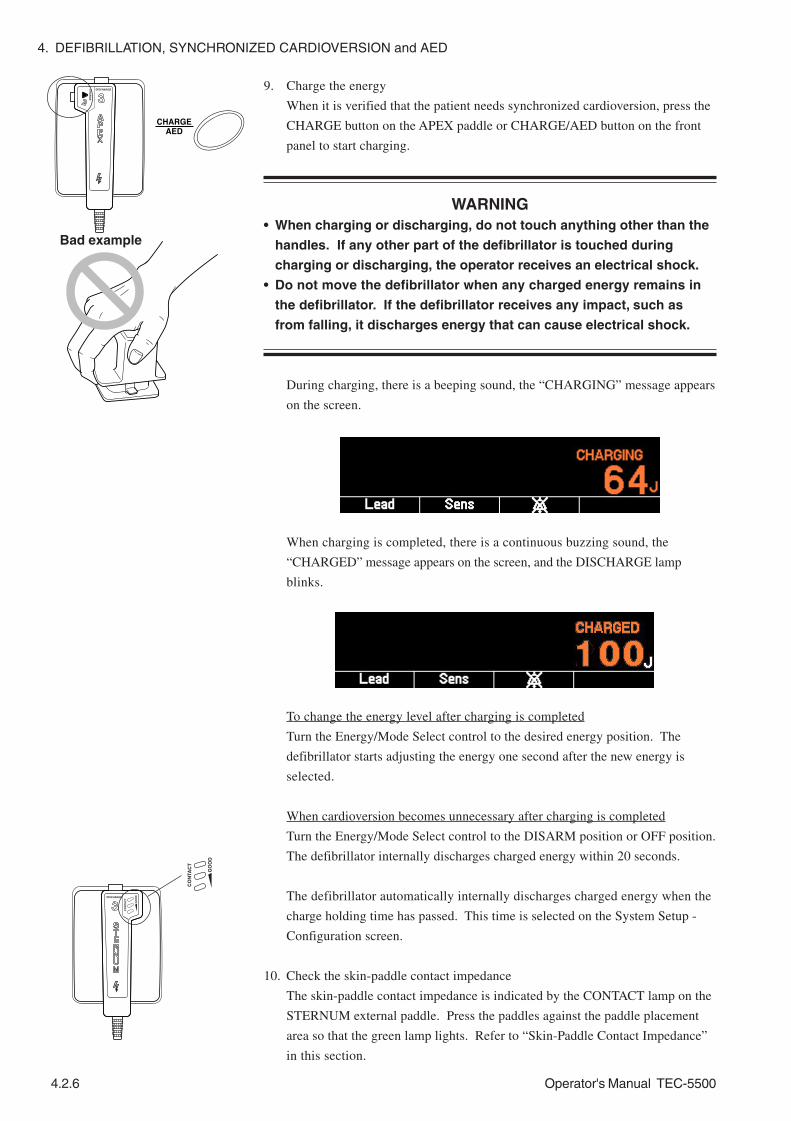
4. DEFIBRILLATION, SYNCHRONIZED CARDIOVERSION and AED
4.2.6 Operator's Manual TEC-5500
9. Charge the energy
When it is verified that the patient needs synchronized cardioversion, press the
CHARGE button on the APEX paddle or CHARGE/AED button on the front
panel to start charging.
WARNING• When charging or discharging, do not touch anything other than the
handles. If any other part of the defibrillator is touched during
charging or discharging, the operator receives an electrical shock.
• Do not move the defibrillator when any charged energy remains in
the defibrillator. If the defibrillator receives any impact, such as
from falling, it discharges energy that can cause electrical shock.
During charging, there is a beeping sound, the “CHARGING” message appears
on the screen.
Bad example
When charging is completed, there is a continuous buzzing sound, the
“CHARGED” message appears on the screen, and the DISCHARGE lamp
blinks.
To change the energy level after charging is completed
Turn the Energy/Mode Select control to the desired energy position. The
defibrillator starts adjusting the energy one second after the new energy is
selected.
When cardioversion becomes unnecessary after charging is completed
Turn the Energy/Mode Select control to the DISARM position or OFF position.
The defibrillator internally discharges charged energy within 20 seconds.
The defibrillator automatically internally discharges charged energy when the
charge holding time has passed. This time is selected on the System Setup -
Configuration screen.
10. Check the skin-paddle contact impedance
The skin-paddle contact impedance is indicated by the CONTACT lamp on the
STERNUM external paddle. Press the paddles against the paddle placement
area so that the green lamp lights. Refer to “Skin-Paddle Contact Impedance”
in this section.

4. DEFIBRILLATION, SYNCHRONIZED CARDIOVERSION and AED
Operator's Manual TEC-5500 4.2.7
Bad example
11. Discharge the energy to the patient
After confirming that the DISCHARGE lamp blinks and the SYNC lamp lights,
press the DISCHARGE buttons on the paddles to discharge the energy to the
patient. Hold the buttons pressed until energy is discharged.
DISCHARGE button
DISCHARGE button
WARNING• Make sure that no one is in contact with either the patient or any
equipment which supports or is connected to the patient.
• Before discharging, confirm that the paddles are firmly pressed
against the chest wall. Failure to follow this warning causes skin
burn or poor energy discharge to the heart.
• Do not discharge near a person or object other than the patient or test
electrode plate or energy checker. This may cause electrical shock to
the person or object.
• Do not discharge with the paddles in the air. This may cause
electrical shock to the operator or damage the defibrillator.
• Do not discharge the energy if the paddles are shorted to each other
by contact gel. It may cause skin burn and poor energy discharge to
the heart.
CAUTIONDo not discharge when the paddles touch each other. This may
damage the defibrillator.
12. If another cardioversion is required, perform necessary medical treatment and
repeat steps 5 and 7 to 11.
Use the edge around each paddle holders to temporarily hold the paddles so
that contact gel does not get on the defibrillator. These holders can only be
used for the adult electrode plate.

4. DEFIBRILLATION, SYNCHRONIZED CARDIOVERSION and AED
4.2.8 Operator's Manual TEC-5500
13. Turn the power off
Turn the Energy/Mode Select control to the OFF position to turn the
defibrillator power off.
NOTEWhile the “Shutdown NOW” message is displayed on the screen, do not
disconnect the power cord from the defibrillator or AC outlet and do not
remove the battery pack from the defibrillator. Otherwise, the internal
data may be damaged.
Thoroughly wipe off the contact gel from the external paddles and defibrillator.
Refer to “Cleaning, Disinfecting and Sterilization” in Section 10.
Put the external paddles to the paddle holders by pressing the paddles onto the
holders.

4. DEFIBRILLATION, SYNCHRONIZED CARDIOVERSION and AED
Operator's Manual TEC-5500 4.2.9
WARNING• Before cardioversion, make sure that no one is in contact with either
the patient or any metal part of any equipment or cables which
supports or is connected to the patient. Failure to follow this
warning causes serious electrical shock or injury.
• Before cardioversion, remove from the patient all electrodes, probes
and transducers from a connector that do not have a “ ” or “ ”
mark. Otherwise, the operator may receive electrical shock and the
connected instrument may be damaged.
• Before cardioversion, remove everything (electrodes, patches, etc.)
from the patient’s chest. When the defibrillator paddle directly
contacts these materials, the discharged energy may cause skin burn
to the patient.
• Before cardioversion, check that the cords and cables of the
electrodes, probes and transducers attached to the patient are
properly connected to a connector that has a “ ” or “ ” mark.
Touching the metal parts of the disconnected cords and cables may
cause electrical shock or injury by discharged energy.
• When using an ESU, use this defibrillator only in the MONITOR mode
and use the ECG electrodes for monitoring. Do not monitor ECG with
disposable pads, external paddles or internal paddles. If ECG is
monitored with pads or paddles, high frequency energy from the
ESU causes abnormal current to flow in the patient and unexpected
discharge. This may damage the defibrillator.
• Use the ECG monitoring electrodes (disposable electrodes) to
monitor the ECG waveforms. Stable ECG cannot be acquired with
the PADDLE lead because it is difficult to hold the paddles stable.
ECG acquired from external paddles, internal paddles or disposable
pads is unstable after discharge because of high polarization
voltage.
• Confirm that there is no noise on the ECG. Noise may be
misrecognized as QRS and discharge might not synchronize with the
patient’s QRS.
• The defibrillator must only be operated by trained and qualified
medical personnel.
• Failure to follow the warnings below may cause skin burn or
insufficient energy discharge and insufficient pacing current to the
heart.
- Do not reuse disposable pads.
- If the pad package is torn, dispose of the pads and do not use
them.
- Do not use the pads if they are past the expiration date on the
package.
Synchronized Cardioversion with Disposable Pads
Important SafetyInformation
4. DEFIBRILLATION, SYNCHRONIZED CARDIOVERSION and AED
4.2.10 Operator's Manual TEC-5500
WARNING continued- Use the disposable pads as soon as possible after opening the
package.
- Do not use the disposable pads if the gel has become dry or if the
gel has become abnormal (the gel has become liquid or is coming
off the edges of the pad, etc).
- Do not use the disposable pads if the gel is dark brown or dark
brown gel is on the protective sheet.
• If any pad or connector gets wet, replace it with a new one. If a wet
pad or connector is used, it may cause electrical shock.
• Do not cardioversion in a wet place. Before cardioversion, move the
patient and defibrillator to a dry place. Otherwise the operator may
get electrical shock.
CAUTION• When using the disposable pads for long term ECG monitoring,
replace them every 24 hours. Failure to follow this instruction may
cause insufficient pacing current and insufficient energy discharge to
the heart.
• Do not attach a disposable pad over another pad. It may cause skin
burn on the patient.
• When performing synchronized cardioversion, confirm that the SYNC
lamp is lit before every discharge. If “Sync mode after CV” is set to
Defib on the System Setup - Configuration screen, the defibrillator
automatically turns to the asynchronous defibrillation mode.
• Do not put heavy objects on the disposable pads or bend the pads. If
the pads get damaged or deteriorated, it may cause skin burn on the
patient.
NOTE• Follow all disposable pad labeling instructions.
• Always prepare the second set of disposable pads before
cardioversion. Use the second set of disposable pads if the gel of the
first set of disposable pads is dry, deteriorated or changes color.
• Before attaching the disposable pads to the patient, clean the skin
where the pads will be attached. If the skin is moist, use a cotton
swab to dry it.
• Only use the pads specified by Nihon Kohden.
• Cardioversion is not available when any Setup screen or System
Setup screen is displayed. Previously confirm and set the necessary
settings on the Setup screen and System Setup-Configuration screen.

4. DEFIBRILLATION, SYNCHRONIZED CARDIOVERSION and AED
Operator's Manual TEC-5500 4.2.11
Procedure 1. Connect the pad adaptor to the defibrillator.
1) Press the paddle release knob of the paddle connector on the front panel
and remove the external paddles from the paddle connector.
2) Connect the pad adaptor to the paddle connector until it clicks.
CAUTIONWhen connecting the pad adapter to the paddle connector, do not
bend or damage the connector pin. Energy cannot be discharged to
the pads.
2. Turn the Energy/Mode Select control to the DISARM position to turn the
power on. Confirm that there is no error message on the screen. For error
messages, refer to Section 9. When operating with AC power, confirm that the
AC lamp is on.
3. Prepare the patient to monitor the ECG waveforms.
When monitoring ECG waveforms with the ECG connection cable and
disposable electrodes,
1) Connect the ECG connection cable to the ECG input connector on the
front panel.
2) Attach the disposable electrodes to the patient. Refer to Section 4
“Preparing for ECG Monitoring”.
3) Clip the ECG connection cable to the electrode. Confirm that electrodes
are not pulled by the ECG connection cable.
To acquire ECG waveforms from another monitor, refer to “Using the ECG
Waveforms from Another Monitor, Paddles or Disposable Pads for
Synchronized Cardioversion” in this section.

4. DEFIBRILLATION, SYNCHRONIZED CARDIOVERSION and AED
4.2.12 Operator's Manual TEC-5500
NOTE• Select a lead so that the whole waveform is displayed on the screen
and the T waveform is not much higher than the QRS waveform.
Otherwise, QRS cannot be recognized correctly.
• If the defibrillator miscounts the narrow width QRS, set “Pacing Pulse
Reject” to OFF on the ECG Setup screen and confirm that QRS is
correctly recognized.
5. Select SYNC mode
1) Press the SYNC button on the front panel to select the synchronized
cardioversion mode. Confirm that the SYNC lamp lights and “SYNC” is
displayed on the screen.
2) Check that the “ ” mark appears on the rising slope of every QRS wave.
The “ ” mark indicates that the defibrillator detects the QRS wave. If the
mark does not appear, correct synchronization is not available. Do the
following to display the “ ” mark on the rising slope of every QRS wave:
- Change the amplitude of the ECG waveforms with the ECG sensitivity
key.
- Change the ECG lead with the ECG lead key.
- Change the electrode position.
NOTE• When the Energy/Mode Select control is set to MONITOR, AED,
DEMAND or FIXED position, the SYNC mode cannot be selected.
• If the Energy/Mode Select control is set to MONITOR, AED, DEMAND or
FIXED position while the SYNC mode is selected (SYNC lamp is lit),
the defibrillator exits the SYNC mode.
4. Press the ECG lead key to select the lead which has the highest QRS wave.
When acquiring a synchronizing signal with the ECG connection cable and
disposable electrodes, usually “II” is selected. When using the ECG waveform
from another monitor, select “AUX”.
WARNINGNever select “TEST” for the ECG lead. “TEST” is for maintenance and
the waveform displayed on the screen is not the patient’s ECG. If
synchronized cardioversion is performed with the TEST lead, the
discharge is not synchronized with the patient’s QRS and it may cause
ventricular fibrillation.

4. DEFIBRILLATION, SYNCHRONIZED CARDIOVERSION and AED
Operator's Manual TEC-5500 4.2.13
3) Attach the pads to the patient’s body, one at a time.
WARNING• Do not attach pads on the papilla, electrodes or medicine on the
patient’s body. Failure to follow this warning causes serious skin
burn.
• Fit the pad closely to the body surface so that current flows uniformly
through the pad. Failure to follow this warning causes serious skin
burn or insufficient energy discharge to the heart.
CAUTIONIf the patient’s body is wet, thoroughly wipe the moisture off the skin
so that the paddles do not short to each other.
NOTEWhen the skin-pad contact is poor, it causes high electrode impedance
and energy cannot be charged.
6. Prepare the disposable pads.
1) To allow firm pad contact with the skin, clean the patient’s chest to remove
oil and dirt, and thoroughly dry the skin. Clip excessive hair, if necessary.
NOTEDo not apply any gel or paste when using disposable pads.
2) Take the disposable pads out of the package and carefully remove the
protective liner from one pad at a time.

4. DEFIBRILLATION, SYNCHRONIZED CARDIOVERSION and AED
4.2.14 Operator's Manual TEC-5500
4) Connect the disposable pads to the pad adaptor.
RA: Between right scapula and spine
LL: On the level of fifth intercostal space and midaxillary line
Apex-Posterior placement
Apex-Anterior placement
RA: Right side of sternum and below the clavicle
LL: On the level of fifth intercostal space and midaxillary line
NOTE• Firmly connect the disposable pads to the pad adaptor until the
connector of the disposable pads clicks.
• When the “Change disposable pads” message appears, the pads may
be faulty. Replace them with new ones. If the message still appears,
stop using the defibrillator and use a different defibrillator.

4. DEFIBRILLATION, SYNCHRONIZED CARDIOVERSION and AED
Operator's Manual TEC-5500 4.2.15
When charging is completed, there is a continuous buzzing sound, the
“CHARGED” message appears on the screen, and the DISCHARGE lamp
blinks.
7. Select the energy level
Turn the Energy/Mode Select control to the desired energy position.
8. Charge the energy
When it is verified that the patient needs synchronized cardioversion, press the
CHARGE/AED button on the front panel to start charging.
WARNING• During charging or discharging, do not touch the pads or connectors.
Failure to follow this warning causes electrical shock to the operator.
• Do not move the defibrillator when any charged energy remains in
the defibrillator. If the defibrillator receives any impact, such as
from falling, it discharges energy that can cause electrical shock.
NOTE• If the CHARGE/AED button is pressed when a disposable pad is
detached from the patient, charging does not start.
• If a disposable pad is detached during or after charging, the
defibrillator automatically discharges energy internally within 20
seconds.
During charging, there is a beeping sound, the “CHARGING” message appears
on the screen.
To change the energy level after charging is completed
Turn the Energy/Mode Select control to the desired energy position. The
defibrillator starts adjusting the energy one second after the new energy is
selected.
When cardioversion becomes unnecessary after charging is completed
Turn the Energy/Mode Select control to the DISARM position or OFF
position. The defibrillator internally discharges charged energy within 20
seconds.

4. DEFIBRILLATION, SYNCHRONIZED CARDIOVERSION and AED
4.2.16 Operator's Manual TEC-5500
11. Turn the power off
Turn the Energy/Mode Select control to the OFF position.
NOTEWhile the “Shutdown NOW” message is displayed on the screen, do not
disconnect the power cord from the defibrillator or AC outlet and do not
remove the battery pack from the defibrillator. Otherwise, the internal
data may be damaged.
Press the paddle release knob of the paddle connector to the right and remove
the pad adaptor from the paddle connector. Hold the connector part to
disconnect the pad adaptor. Otherwise the connector gets damaged and the
cable breaks.
Dispose of the disposable pads. Refer to “Cleaning, Disinfecting and
Sterilization” in Section 10.
The defibrillator automatically internally discharges charged energy when the
charge holding time has passed. This time is selected on the System Setup -
Configuration screen.
9. Discharge the energy to the patient
After confirming that the DISCHARGE lamp blinks and SYNC lamp lights,
press the DISCHARGE button on the front panel to discharge the energy to the
patient. Hold the buttons pressed until energy is discharged.
WARNING• Before discharging, confirm that the pads are firmly applied to the
chest wall. Failure to follow this warning causes skin burn or poor
energy discharge to the heart.
• Do not discharge if the pads overlap each other or are shorted to
each other by anything conductive such as contact gel. This may
cause skin burn and poor energy discharge to the heart.
• Make sure that no one is in contact with either the patient or any
equipment which supports or is connected to the patient.
10. If another cardioversion is required, perform necessary medical treatment and
repeat steps 5 and 7 to 9.

4. DEFIBRILLATION, SYNCHRONIZED CARDIOVERSION and AED
Operator's Manual TEC-5500 4.2.17
Synchronized Cardioversion with Internal Paddles
Important SafetyInformation
By directly applying the internal paddles to the heart, cardioversion during open
chest operation is available.
WARNING• Before cardioversion, make sure that no one is in contact with either
the patient or any metal part of any equipment or cables which
supports or is connected to the patient. Failure to follow this warning
causes serious electrical shock or injury.
• Before cardioversion, remove from the patient all electrodes, probes
and transducers from a connector that do not have a “ ” or “ ”
mark. Otherwise, the operator may receive electrical shock and the
connected instrument may be damaged.
• Before cardioversion, remove everything (electrodes, patches, etc.)
from the patient’s chest. When the defibrillator paddle directly contacts
these materials, the discharged energy may cause skin burn to the
patient.
• Before cardioversion, check that the cords and cables of the electrodes,
probes and transducers attached to the patient are properly connected
to a connector that has a “ ” or “ ” mark. Touching the metal parts
of the disconnected cords and cables may cause electrical shock or
injury by discharged energy.
• When using an ESU, use this defibrillator only in the MONITOR mode
and use the ECG electrodes for monitoring. Do not monitor ECG with
disposable pads, external paddles or internal paddles. If ECG is
monitored with pads or paddles, high frequency energy from the ESU
causes abnormal current to flow in the patient and unexpected
discharge. This may damage the defibrillator.
• Use the ECG monitoring electrodes (disposable electrodes) to monitor
the ECG waveforms. Stable ECG cannot be acquired with the PADDLE
lead because it is difficult to hold the paddles stable. ECG acquired
from external paddles, internal paddles or disposable pads is unstable
after discharge because of high polarization voltage.
• Confirm that there is no artifact on the ECG. If there is artifact on the
ECG, signals other than ECG are misrecognized to be QRS and
accidental discharge may occur which is not synchronized with the
patient’s QRS wave.
• The defibrillator must only be operated by trained and qualified medical
personnel.
• Sterilize the internal paddles before use. Failure to sterilize the
paddles may cause serious infection.
• Pay careful attention to the energy selection when using internal paddles.
Applying high energy to the heart may cause cardiac muscle necrosis.
Low energy is recommended.

4. DEFIBRILLATION, SYNCHRONIZED CARDIOVERSION and AED
4.2.18 Operator's Manual TEC-5500
Procedure
NOTE• Select the appropriate energy and appropriate size of the internal
paddles according to the patient. Only use the paddles specified by
Nihon Kohden.
• Cardioversion is not available when any Setup screen or System
Setup screen is displayed. Before using the defibrillator, confirm and
set the necessary settings on the Setup screen and System Setup-
Configuration screen.
Synchronized cardioversion should be performed with the minimum effective
energy. It is reported that the cardiac muscle may necrose if high energy is
repeatedly applied to the heart with internal paddles. Refer to “Reference” in
Section 11.
1. Connect the internal paddles to the defibrillator.
1) Press the paddle release knob of the paddle connector to the right and
remove the external paddles from the paddle connector.
Warning - continued
• Do not perform cardioversion in a wet place. Before cardioversion,
move the patient and defibrillator to a dry place. Otherwise the
operator may get electrical shock.
CAUTION• Do not twist the internal paddle while holding the electrode or give
strong impact to the paddle. It damages the electrode.
• When performing synchronized cardioversion, confirm that the SYNC
lamp is lit before every discharge. If “Sync mode after CV” is set to
Defib on the System Setup - Configuration screen, the defibrillator
automatically turns to the asynchronous defibrillation mode.

4. DEFIBRILLATION, SYNCHRONIZED CARDIOVERSION and AED
Operator's Manual TEC-5500 4.2.19
3. Prepare the patient to monitor the ECG waveforms.
When monitoring ECG waveform with the ECG connection cable and
disposable electrodes,
1) Connect the ECG connection cable to the ECG input connector on the
front panel.
2) Attach the disposable electrodes to the patient. Refer to Section 4
“Preparing for ECG Monitoring”.
3) Clip the ECG connection cable to the electrode. Confirm that electrodes
are not pulled by the ECG connection cable.
2) Connect the internal paddles to the paddle connector until it clicks.
CAUTIONWhen connecting the pad adapter to the paddle connector, do not
bend or damage the connector pin. Energy cannot be discharged to
the pads.
2. Turn the Energy/Mode Select control to the DISARM position to turn the
power on. Confirm that there is no error message on the screen. For error
messages, refer to Section 9. When operating with AC power, confirm that the
AC lamp is on.
To acquire ECG waveform from another monitor, refer to “Using the ECG
Waveforms from Another Monitor, Paddles or Disposable Pads for
Synchronized Cardioversion” in this section.
4. Press the ECG lead key to select the lead which has the highest QRS wave.
When acquiring a synchronizing signal with the ECG connection cable and
disposable electrodes, usually “II” is selected. When using the ECG waveform
from another monitor, select “AUX”.

4. DEFIBRILLATION, SYNCHRONIZED CARDIOVERSION and AED
4.2.20 Operator's Manual TEC-5500
WARNINGNever select “TEST” for the ECG lead. “TEST” is for maintenance and
the waveform displayed on the screen is not the patient’s ECG. If
synchronized cardioversion is performed with the TEST lead, the
discharge is not synchronized with the patient’s QRS and it may cause
ventricular fibrillation.
NOTE• Select a lead so that the whole waveform is displayed on the screen
and the T waveform is not much higher than the QRS waveform.
Otherwise, QRS cannot be recognized correctly.
• If the defibrillator miscounts the narrow width QRS, set “Pacing Pulse
Reject” to OFF on the ECG Setup screen and confirm that QRS is
correctly recognized.
5. Select SYNC mode
1) Press the SYNC button on the front panel to select the synchronized
cardioversion mode. Confirm that the SYNC lamp lights and “SYNC” is
displayed on the screen.
2) Check that the “ ” mark appears on the rising slope of every QRS wave.
The “ ” mark indicates that the defibrillator detects the QRS wave. If the
mark does not appear, correct synchronization is not available. Do the
following to display the “ ” mark on the rising slope of every QRS wave:
- Change the amplitude of the ECG waveforms with the ECG sensitivity
key.
- Change the ECG lead with the ECG lead key.
- Change the electrode position.
NOTE• When the Energy/Mode Select control is set to MONITOR, AED,
DEMAND or FIXED position, the SYNC mode cannot be selected.
• If the Energy/Mode Select control is set to MONITOR, AED, DEMAND or
FIXED position while the SYNC mode is selected (SYNC lamp is lit),
the defibrillator exits the SYNC mode.

4. DEFIBRILLATION, SYNCHRONIZED CARDIOVERSION and AED
Operator's Manual TEC-5500 4.2.21
guard
7. Select the energy level
Turn the Energy/Mode Select control to the desired energy position.
When the internal paddles are used, 50 J or below can be selected. If above 50
J is selected, the “Set energy to 50 J or less” message appears on the screen and
the selected energy cannot be charged.
8. Charge the energy
When it is verified that the patient needs synchronized cardioversion, press the
CHARGE/AED button on the front panel to start charging.
WARNING• During charging and discharging, grip the internal paddles between
the guard at the top of the handle and the cable. If you grip the
handle between the electrode and the guard, you may get an
electrical shock.
• Do not carry or move the defibrillator with the charged energy
remaining in the defibrillator. If the defibrillator falls down, it
discharges energy and can cause electrical shock.
6. Position the internal paddles
Position the sterilized internal paddles against the right and the left atria of the
heart.
NOTE• It is not necessary to consider the polarities of the internal paddle
electrodes.
• For better contact between the internal paddles and heart, place
sterilized gauze moistened with physiological saline solution
between each internal paddle and the heart.

4. DEFIBRILLATION, SYNCHRONIZED CARDIOVERSION and AED
4.2.22 Operator's Manual TEC-5500
During charging, there is a beeping sound, the “CHARGING” message appears
on the screen.
When charging is completed, there is a continuous buzzing sound, the
“CHARGED” message appears on the screen, and the DISCHARGE lamp
blinks.
To change the energy level after charging is completed
Turn the Energy/Mode Select control to the desired energy position. The
defibrillator starts adjusting the energy one second after the new energy is
selected.
NOTEIf above 50 J is selected, the defibrillator immediately discharges energy
internally.
When cardioversion becomes unnecessary after charging is completed
Turn the Energy/Mode Select control to the DISARM position or OFF position.
The defibrillator internally discharges charged energy within 20 seconds.
The defibrillator automatically internally discharges charged energy when the
charge holding time has passed. This time is selected on the System Setup -
Configuration screen.
9. Discharge the energy to the patient
After confirming that the DISCHARGE lamp blinks and SYNC lamp lights,
press the DISCHARGE button on the front panel to discharge the energy to the
patient. Hold the buttons until energy is discharged. Firmly hold the handles
of the internal paddles until energy is discharged.

4. DEFIBRILLATION, SYNCHRONIZED CARDIOVERSION and AED
Operator's Manual TEC-5500 4.2.23
WARNING• Make sure that no one is in contact with either the patient or any
equipment which supports or is connected to the patient.
• Before discharging, confirm that the paddles are firmly positioned
against the heart. Failure to follow this warning causes serious skin
burn or poor energy discharge to the heart.
• Do not discharge near a person or object other than the patient or
test electrode plate or energy checker. This may cause electrical
shock to the person or object.
• Do not discharge with the paddles in the air. This may cause
electrical shock to the operator or damage the defibrillator.
CAUTIONDo not discharge when the paddles touch each other. This may
damage the defibrillator.
10. If another cardioversion is required, perform necessary medical treatment and
repeat steps 5 to 9.
11. Turn the power off
Turn the Energy/Mode Select control to the OFF position.
NOTEWhile the “Shutdown NOW” message is displayed on the screen, do not
disconnect the power cord from the defibrillator or AC outlet and do not
remove the battery pack from the defibrillator. Otherwise, the internal
data may be damaged.
Press the paddle release knob of the paddle connector to the right and remove
the internal paddles from the paddle connector. Hold the connector part to
disconnect the paddle connector. Otherwise the connector gets damaged and
the cable breaks.
Wash off blood from the internal paddles and sterilize them. Refer to
“Cleaning, Disinfecting and Sterilization” in Section 10.

4. DEFIBRILLATION, SYNCHRONIZED CARDIOVERSION and AED
4.2.24 Operator's Manual TEC-5500
This page is intentionally left blank.

Operator's Manual TEC-5500 4.3C.1
AED
AED Screen .....................................................................................................................4.3.1
Important Safety Information ...........................................................................................4.3.2
AED Flowchart .................................................................................................................4.3.4
Preparation for AED Mode ......................................................................................4.3.5
AED Procedure ................................................................................................................4.3.6
When Nonshockable Rhythm Is Detected In AED Analysis ................................. 4.3.15

4.3C.2 Operator's Manual TEC-5500
This page is intentionally left blank.

4. DEFIBRILLATION, SYNCHRONIZED CARDIOVERSION and AED
Operator's Manual TEC-5500 4.3.1
AED Screen
Screen Example
In AED mode, the defibrillator analyzes the ECG waveforms (AED analysis). When
shockable waveform (Ventricular Fibrillation and Ventricular tachycardia) is
detected, the defibrillator automatically charges the preset energy.
Heart rateECG lead
Sensitivity
ECG
Alarm off mark
AC power operation
Charged energy
AED mode
1st charge energy (currently selected energy is highlighted.)
2nd charge energy
3rd charge energy
Pause keyWhen AED mode is selected, the Multi-function key changes to the Pause key totemporarily stop AED analysis.

4. DEFIBRILLATION, SYNCHRONIZED CARDIOVERSION and AED
4.3.2 Operator's Manual TEC-5500
Important Safety Information
WARNING• Before defibrillation, make sure that no one is in contact with either
the patient or any metal part of any equipment or cables which
supports or is connected to the patient. Failure to follow this
warning causes serious electrical shock or injury.
• When using an ESU, use this defibrillator only in the MONITOR mode
and use the ECG electrodes for monitoring. Do not monitor ECG with
disposable pads, external paddles or internal paddles. If ECG is
monitored with pads or paddles, high frequency energy from the
ESU causes abnormal current to flow in the patient and unexpected
discharge. This may damage the defibrillator.
• Use the ECG monitoring electrodes (disposable electrodes) to
monitor the ECG waveforms. Stable ECG cannot be acquired with
the PADDLE lead because it is difficult to hold the paddles stable.
ECG acquired from external paddles, internal paddles or disposable
pads is unstable after discharge because of high polarization
voltage.
• Confirm that there is no noise on the ECG. Noise may be
misrecognized as QRS and discharge might not synchronize with the
patient’s QRS.
• The defibrillator must only be operated by trained and qualified
medical personnel.
• Failure to follow the warnings below may cause skin burn or
insufficient energy discharge and insufficient pacing current to the
heart.
- Do not reuse disposable pads.
- If the pad package is torn, dispose of the pads and do not use
them.
- Do not use the pads if they are past the expiration date on the
package.
- Use the disposable pads as soon as possible after opening the
package.
- Do not use the disposable pads if the gel has become dry or if the
gel has become abnormal (the gel has become liquid or is coming
off the edges of the pad, etc).
- Do not use the disposable pads if the gel is dark brown or dark
brown gel is on the protective sheet.
• If any pad or connector gets wet, replace it with a new one. If a wet
pad or connector is used, it may cause electrical shock.

4. DEFIBRILLATION, SYNCHRONIZED CARDIOVERSION and AED
Operator's Manual TEC-5500 4.3.3
CAUTION• When using the disposable pads for long term ECG monitoring,
replace them every 24 hours. Failure to follow this instruction may
cause insufficient pacing current and insufficient energy discharge to
the heart.
• Do not attach a disposable pad over another pad. It may cause skin
burn on the patient.
• Do not put heavy objects on the disposable pads or bend the pads. If
the pads get damaged or deteriorated, it may cause skin burn on the
patient.
NOTE• AED mode can be used for patients 8 years or older or 25 kg or more.
• Follow all disposable pad labeling instructions.
• Always prepare the second set of disposable pads before
defibrillation. Use the second set of disposable pads if the gel of the
first set of disposable pads is dry, deteriorated or changes color.
• Before attaching the disposable pads to the patient, clean the skin
where the pads will be attached. If the skin is moist, use a cotton
swab to dry it.
• Defibrillation is not available when any Setup screen or System Setup
screen is displayed. Before using the defibrillator, confirm and set the
necessary settings on the Setup screen and System Setup-
Configuration screen.

4. DEFIBRILLATION, SYNCHRONIZED CARDIOVERSION and AED
4.3.4 Operator's Manual TEC-5500
shockable rhythm
Defibrillation not necessary. Check ECG.Defibrillation necessary. Check ECG.
Press CHARGE/AED button.
Check pulse **
If no pulse, start CPR. **
nonshockable rhythm
Each shock or Each Seq.
OFF
Press CHARGE/AED button
Turn Energy/Mode Select control to AED
VF analysis startsAnalyzing VFStand clear
Result?
End sequence?
Charging startsCHARGING
Charging finishesCHARGED
Stand clear and press DISCHARGE buttons.
If no pulse, press AED button. **
CPR timing sound generates
Press DISCHARGE button
CPR time(s)
When set to OFF
When set to any number
AED button 2nd or later Analysis
(start analysis manually?)
AED button 2nd or later Analysis
(start analysis manually?)
AED button First Analysis
End after selected time
ON
Yes
No
OFF
Each shock
Each Seq. or OFF
*
AED Flowchart
AED
CPR
* If defibrillation becomes necessary during CPR, press the CHARGE/AED
button. Analysis immediately starts and operation proceeds from the “VF
analysis starts” step in the flowchart.
** “Check pulse”, “If no pulse, start CPR” and “If no pulse, press AED button”
messages are not displayed when the “Check Pulse Pattern” on the System
Setup screen is set to 3 (no checking pulse).
Bold: Displayed message
Italic: Settings in System Setup screen
User operation
Instrument operation

4. DEFIBRILLATION, SYNCHRONIZED CARDIOVERSION and AED
Operator's Manual TEC-5500 4.3.5
Change the following settings, if necessary. Refer to “System Setup Screen” in
Section 3. The factory default settings are underlined.
AED
• AED Energy ( 2 to 100, 150, 200, 270 J)
The first, second and third energy in each discharge/AED sequence. When a
shockable waveform is detected, the selected energy is automatically charged.
The number of discharges for one sequence is set in “Discharge/AED sequence”.
• Energy after 3rd discharge (Repeat cycle, 3rd energy)
The energy after the third discharge.
• AED button First Analysis (ON, OFF)
When AED mode is selected, select or not to start AED analysis (shockable
waveform detection) by pressing the CHARGE/ED button. If “ON” (default
setting) is selected, you must press the CHARGE/AED button to start AED
analysis.
• AED button 2nd or later Analysis (Each shock, Each Seq., OFF)
Select whether to manually or automatically start AED analysis after each
discharge or each sequence. Select “OFF” to automatically start AED analysis. If
“Each shock” or “Each Seq.” is selected, you must press the CHARGE/AED
button to start AED analysis.
• Discharge/AED sequence (2, 3, 4)
The number of discharges for one sequence.
• Pause time (30, 60, 120, 180 seconds and OFF)
In AED mode, the Multi-function key changes to the Pause key. Background
AED analysis can be temporarily paused by pressing the PAUSE key.
CPR
• CPR time (s) (30, 60, 90, 120, 150, 180, 210 seconds, OFF)
The time until starting AED analysis in background after a discharge/AED
sequence.
• CPR timing sound (60, 70, 80, 90, 100, 110, 120 seconds, OFF)
Duration of CPR timing sound.
Preparation for AED Mode

4. DEFIBRILLATION, SYNCHRONIZED CARDIOVERSION and AED
4.3.6 Operator's Manual TEC-5500
1. Confirm that the patient is unconscious and has no respiration and no pulse.
CAUTION• Before AED analysis or defibrillation, confirm that the patient is
unconscious and has no respiration and no pulse.
• The ECG of a child or a patient with an implanted pacemaker cannot
be analyzed correctly. For these patients, follow the physician’s
instruction.
2. Connect the pad adaptor to the defibrillator.
1) Press the paddle release knob of the paddle connector on the front panel
and remove the external paddles from the paddle connector.
2) Connect the pad adaptor to the paddle connector until it clicks.
CAUTIONWhen connecting the pad adapter to the paddle connector, do not
bend or damage the connector pin. Energy cannot be discharged to
the pads.
3. Turn the Energy/Mode Select control to the AED position to turn the power on.
Confirm that there is no error message on the screen. For error messages, refer
to Section 9. When operating with AC power, confirm that the AC lamp is on.
When AED mode is selected, the Multi-function key changes to the Pause key.
To temporarily pause background AED analysis, press the Pause key. The
pause time is set on the System Setup - Configuration screen. When the Pause
key is pressed, it changes to the Resume key. To start AED analysis, press the
Resume key.
AED Procedure

4. DEFIBRILLATION, SYNCHRONIZED CARDIOVERSION and AED
Operator's Manual TEC-5500 4.3.7
4. Confirm that “PADDLE” is selected for ECG lead.
NOTEIn AED mode, other ECG leads cannot be selected.
5. Prepare the disposable pads.
1) To allow firm pad contact with the skin, clean the patient’s chest to remove
oil, moisture and dirt, and thoroughly dry the skin. Clip excessive hair, if
necessary.
NOTEDo not apply any gel or paste when using disposable pads.
2) Take the disposable pads out of the package and carefully remove the
protective liner from one pad at a time.
3) Attach the pads to the patient’s body, one at a time.
Apex-Anterior placement
RA: Right side of sternum and below the clavicle
LL: On the level of fifth intercostal space and midaxillary line
WARNING• Do not attach pads on the papilla, electrodes or medicine on the
patient’s body. Failure to follow this warning causes serious skin
burn.
• Fit the pad closely to the body surface so that current flows uniformly
through the pad. Failure to follow this warning causes serious skin
burn or insufficient energy discharge to the heart.

4. DEFIBRILLATION, SYNCHRONIZED CARDIOVERSION and AED
4.3.8 Operator's Manual TEC-5500
CAUTIONIf the patient’s body is wet, thoroughly wipe the moisture off the skin
so that the paddles do not short to each other.
NOTEWhen the skin-pad contact is poor, it causes high electrode impedance
and energy cannot be charged.
4) Connect the disposable pads to the pad adaptor.
NOTE• Firmly connect the disposable pads to the pad adaptor until the
connector of the disposable pads clicks. If the pads are not attached
firmly or the pads are not connected to the pad adaptor, noise
appears on the ECG waveform.
• When the “Change disposable pads” message appears, the pads may
be faulty. Replace them with new ones. If the message still appears,
stop using the defibrillator and use a different defibrillator.
6. Confirm the selected energy values
Three selected energy values are displayed on the upper screen. The 1st energy
is selected. The selected energy is highlighted. Confirm that the energy is
proper.
To change the energy values, use the “AED Energy” setting in the System
Setup - Configuration screen. Refer to Section 3.
The following waveforms are saved in memory.
- Waveform of 10 seconds before and 12 seconds after discharge
- Waveform of 6 seconds after the CHARGE/AED button is pressed.
If you want to record any other waveform, press the Record key and print the
waveform on the recording paper. Waveform of 6 seconds after the CHARGE/
AED button is pressed can be printed as a report. For details refer to Section 8.

4. DEFIBRILLATION, SYNCHRONIZED CARDIOVERSION and AED
Operator's Manual TEC-5500 4.3.9
7. Start AED analysis.
Stop the life saving treatment such as CPR, keep the patient at rest and do not
touch or move the patient, pad adaptor and disposable pad cable. Then press
the CHARGE/AED button on the front panel. The background AED analysis
starts and the “Stand clear” message appears on the screen.
To automatically start background AED analysis, set “AED button First
Analysis” in the System Setup - Configuration screen to “OFF”.
WARNINGWhen you perform defibrillation in an ambulance, stop the car.
CAUTIONDuring AED analysis, stop life saving treatment such as CPR. Do not
touch or move the patient, pad adapter and disposable pad cable.
Correct analysis result cannot be obtained.
NOTEIf a shockable rhythm is detected after the CHARGE/AED button is
pressed, the defibrillator automatically starts charging the selected
(highlighted) energy. Therefore, take much care for handling the
CHARGE/AED button.
Waveforms of 6 seconds after the CHARGE/AED button is pressed and the
analysis result can be recorded as VF Analysis report recording. Up to 124
waveforms can be saved in memory. The oldest 31 waveforms are deleted
when you save over 124 waveforms. For details refer to Section 8.
selected energy
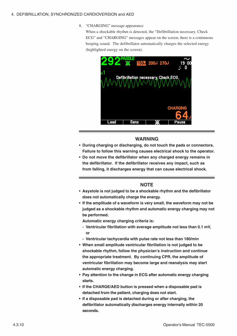
4. DEFIBRILLATION, SYNCHRONIZED CARDIOVERSION and AED
4.3.10 Operator's Manual TEC-5500
8. “CHARGING” message appearance
When a shockable rhythm is detected, the “Defibrillation necessary. Check
ECG” and “CHARGING” messages appear on the screen, there is a continuous
beeping sound. The defibrillator automatically charges the selected energy
(highlighted energy on the screen).
WARNING• During charging or discharging, do not touch the pads or connectors.
Failure to follow this warning causes electrical shock to the operator.
• Do not move the defibrillator when any charged energy remains in
the defibrillator. If the defibrillator receives any impact, such as
from falling, it discharges energy that can cause electrical shock.
NOTE• Asystole is not judged to be a shockable rhythm and the defibrillator
does not automatically charge the energy.
• If the amplitude of a waveform is very small, the waveform may not be
judged as a shockable rhythm and automatic energy charging may not
be performed.
Automatic energy charging criteria is:
- Ventricular fibrillation with average amplitude not less than 0.1 mV,
or
- Ventricular tachycardia with pulse rate not less than 180/min
• When small amplitude ventricular fibrillation is not judged to be
shockable rhythm, follow the physician’s instruction and continue
the appropriate treatment. By continuing CPR, the amplitude of
ventricular fibrillation may become large and reanalysis may start
automatic energy charging.
• Pay attention to the change in ECG after automatic energy charging
starts.
• If the CHARGE/AED button is pressed when a disposable pad is
detached from the patient, charging does not start.
• If a disposable pad is detached during or after charging, the
defibrillator automatically discharges energy internally within 20
seconds.

4. DEFIBRILLATION, SYNCHRONIZED CARDIOVERSION and AED
Operator's Manual TEC-5500 4.3.11
9. “CHARGED” message appearance
When charging is completed, there is a continuous buzzing sound, the “Stand
clear and press DISCHARGE button” and “CHARGED” messages appear on
the screen, and the DISCHARGE lamp blinks.
When defibrillation becomes unnecessary after charging is completed
To quit defibrillation, turn the Energy/Mode Select control to the DISARM
position or OFF position to internally discharge the charged energy.
After charging is complete, if nonshockable rhythm is detected, the
defibrillator automatically discharges the charged energy internally. For the
nonshockable rhythm, refer to “When Nonshockable Rhythm Is Detected In
AED Analysis” in this section.
The time until internal discharge is set at “Charge holding time” on the
System Setup - Configuration screen.
WARNING• During charging or discharging, do not touch the pads or connectors.
Failure to follow this warning causes electrical shock to the operator.
• Do not move the defibrillator when any charged energy remains in
the defibrillator. If the defibrillator receives any impact, such as
from falling, it discharges energy that can cause electrical shock.

4. DEFIBRILLATION, SYNCHRONIZED CARDIOVERSION and AED
4.3.12 Operator's Manual TEC-5500
10. Discharge the energy to the patient
Confirm that the DISCHARGE lamp blinks. Then press the DISCHARGE
button on the front panel to discharge the energy to the patient.
WARNING• Before defibrillation, make sure that no one is in contact with either
the patient or any metal part of any equipment or cables which
supports or is connected to the patient. Failure to follow this
warning causes serious electrical shock or injury.
• Before defibrillation, remove from the patient all electrodes, probes
and transducers from a connector that do not have a “ ” or “ ”
mark. Otherwise, the operator may receive electrical shock and the
connected instrument may be damaged.
• Before defibrillation, remove everything (electrodes, patches, etc.)
from the patient’s chest. When the defibrillator paddle directly
contacts these materials, the discharged energy may cause skin burn
to the patient.
• Before defibrillation, check that the cords and cables of the
electrodes, probes and transducers attached to the patient are
properly connected to a connector that has a “ ” or “ ” mark.
Touching the metal parts of the disconnected cords and cables may
cause electrical shock or injury by discharged energy.
• Do not perform defibrillation in a wet place. Before defibrillation,
move the patient and defibrillator to a dry place. Otherwise the
operator may get electrical shock.
• Never discharge near a person or object other than the patient or
test electrode plate or energy checker. It may cause electrical shock
to the person or damage the object.
• Before discharging, confirm that the pads are firmly applied to the
chest wall. Failure to follow this warning causes skin burn or poor
energy discharge to the heart.
• During charging or discharging, do not touch the pads or connectors.
Failure to follow this warning causes electrical shock to the operator.
• Do not discharge if the pads overlap each other or are shorted to
each other by anything conductive such as contact gel. This may
cause skin burn and poor energy discharge to the heart.
NOTEFirmly press the DISCHARGE button.
After defibrillation, the defibrillator returns to the condition of before AED
analysis starts. The selected energy switches to the next energy. The next
energy is highlighted on the upper screen.

4. DEFIBRILLATION, SYNCHRONIZED CARDIOVERSION and AED
Operator's Manual TEC-5500 4.3.13
11. Start AED analysis for the second discharge.
The defibrillator automatically starts reanalysis (when “AED button 2nd or
later analysis” is set to “Each Seq.” (default setting) or “OFF” on the System
Setup - Configuration screen).
When the analysis result is shockable rhythm, the defibrillator starts charging
the 2nd energy. Follow steps 8 to 10 and discharge the energy to the patient.
When the analysis result is nonshockable rhythm, refer to “When
Nonshockable Rhythm Is Detected In AED Analysis” in this section.
12. Start AED analysis for the third discharge.
The defibrillator automatically starts reanalysis (when “AED button 2nd or
later analysis” is set to “Each Seq.” (default setting) or “OFF” on the System
Setup - Configuration screen).
When the analysis result is shockable rhythm, the defibrillator starts charging
the 3rd energy. Follow steps 8 to 10 and discharge the energy to the patient.
When the analysis result is nonshockable rhythm, refer to “When
Nonshockable Rhythm Is Detected In AED Analysis” in this section.
13. After three sets of analysis (when “Discharge/AED sequence” (number of
discharges for one sequence) is set to “3” (default setting) on the System Setup
- Configuration screen), charging and defibrillation are performed and the
defibrillation failed, do necessary treatments such as CPR. The CPR timing
sound occurs according to the setting value at the “CPR timing sound” on the
System Setup - Configuration screen.
During CPR, to temporarily pause background AED analysis, press the Pause
key. When the Pause key is pressed, it changes to the Resume key. To start
backgrond AED analysis, press the Resume key. The CPR timing sound stops.
NOTEWhen defibrillation becomes necessary during CPR, press the CHARGE/
AED button to immediately start analysis.
14. If the patient needs defibrillation after CPR, repeat the steps from 7. On the
System Setup - Configuration screen, you can select two types of energy
selection after the 3rd defibrillation. Refer to Section 3.

4. DEFIBRILLATION, SYNCHRONIZED CARDIOVERSION and AED
4.3.14 Operator's Manual TEC-5500
15. Turn the power off
Turn the Energy/Mode Select control to the OFF position.
NOTEWhile the “Shutdown NOW” message is displayed on the screen, do not
disconnect the power cord from the defibrillator or AC outlet and do not
remove the battery pack from the defibrillator. Otherwise, the internal
data may be damaged.
Press the paddle release knob of the paddle connector to the right and remove
the pad adaptor from the paddle connector. Hold the connector part to
disconnect the pad adaptor. Otherwise the connector gets damaged and the
cable breaks.
Dispose of the disposable pads. Refer to “Cleaning, Disinfecting and
Sterilization” in Section 10.

4. DEFIBRILLATION, SYNCHRONIZED CARDIOVERSION and AED
Operator's Manual TEC-5500 4.3.15
When NonshockableRhythm Is Detected In AEDAnalysis
In AED analysis, nonshockable rhythm is detected in the following cases.
• Asystole
• Ventricular fibrillation with average amplitude less than 0.1 mV
• Ventricular tachycardia with pulse rate less than 180/min
With the above analysis result, energy is not charged automatically. Perform
appropriate treatment according to emergency life saving protocol. If the patient
condition changes, perform AED analysis again and follow the physician’s
instruction.
NOTE• If the amplitude of a waveform is very small, the waveform may not be
judged as a shockable rhythm and automatic energy charging may not
be performed.
Automatic energy charging standard is:
- Ventricular fibrillation with average amplitude not less than 0.1 mV,
or
- Ventricular tachycardia with pulse rate not less than 180/min
• When small amplitude ventricular fibrillation is not judged to be a
shockable rhythm, follow the physician’s instruction and continue
the appropriate treatment. By continuing CPR, the amplitude of
ventricular fibrillation may become large and reanalysis may start
automatic energy charging.

4. DEFIBRILLATION, SYNCHRONIZED CARDIOVERSION and AED
4.3.16 Operator's Manual TEC-5500
This page is intentionally left blank.

Operator's Manual TEC-5500 5C.1
Section 5 Pacing
About Pacing.......................................................................................................................5.1
Important Safety Information ................................................................................................5.2
Pacing in FIXED mode .........................................................................................................5.3
Information on the Pacing Screen in FIXED Mode .....................................................5.3
Procedure..................................................................................................................5.4
Pacing in DEMAND mode ................................................................................................. 5.11
Information on the Pacing Screen in DEMAND Mode .............................................. 5.11
Procedure................................................................................................................ 5.12

5C.2 Operator's Manual TEC-5500
This page is intentionally left blank.

5. PACING (TEC-5531 Series Only)
Operator's Manual TEC-5500 5.1
About Pacing
Noninvasive fixed and demand pacing is only available with TEC-5531 series
defibrillators. After defibrillation, if bradycardia is observed, immediate electric
stimulation can be given through the patient’s chest with the disposable pads. The
ECG waveforms during pacing can be monitored continuously with the ECG
connection cable and disposable electrodes.
Two pacing modes are provided with the TEC-5531 series defibrillators.
FIXED mode: Pacing current is output at the selected pacing rate.
DEMAND mode: When there is no spontaneous heart beat, pacing current is
output at the selected pacing rate. When there is a
spontaneous heart beat and the next heart beat does not occur,
pacing current is output at the selected pacing rate.

5. PACING (TEC-5531 Series Only)
5.2 Operator's Manual TEC-5500
Important Safety Information
WARNING• Do not perform pacing while using an ESU. Before using the ESU, turn the
defibrillator power off and remove disposable pads from the patient.
Otherwise, high frequency energy from the ESU causes abnormal current to
flow into the patient and causes electrical burn, shock or other injury. It also
damages the defibrillator.
• Always monitor the ECG waveform with the ECG connection cable and ECG
electrodes.
• The defibrillator must only be operated by trained and qualified medical
personnel.
• Confirm that there is no noise on the ECG. Noise may be misrecognized as
QRS and discharge might not synchronize with the patient’s QRS.
• Failure to follow the warnings below may cause skin burn or insufficient
energy discharge and insufficient pacing current to the heart.
- Do not reuse disposable pads.
- If the pad package is torn, dispose of the pads and do not use them.
- Do not use the pads if they are past the expiration date on the package.
- Use the disposable pads as soon as possible after opening the package.
- Do not use the disposable pads if the gel has become dry or if the gel has
become abnormal (the gel has become liquid or is coming off the edges of
the pad, etc).
- Do not use the disposable pads if the gel is dark brown or dark brown gel is
on the protective sheet.
• If any pad or connector gets wet, replace it with a new one. If a wet pad or
connector is used, it may cause electrical shock.
• When using the disposable pads for long term pacing, replace them every
hour. Failure to follow this warning may cause skin burn or insufficient
energy discharge and pacing current to the heart.
CAUTION• When using the disposable pads for long term ECG monitoring, replace them
every 24 hours. Failure to follow this instruction may cause insufficient
pacing current and insufficient energy discharge to the heart.
• Check that the pacing pulse is effective by observing ECG on the screen.
• Do not attach a disposable pad over another pad. It may cause skin burn on
the patient.
• Do not put heavy objects on the disposable pads or bend the pads. If the
pads get damaged or deteriorated, it may cause skin burn on the patient.
NOTEFollow all disposable pad labeling instructions.

5. PACING (TEC-5531 Series Only)
Operator's Manual TEC-5500 5.3
Pacing in FIXED mode
Information on the PacingScreen in FIXED Mode
The following information can be displayed on the pacing screen in FIXED mode.
Pacing pulse output point
QRS sync mark
Heart rate
Fixed pacing mode
Pacing ratepacing current
ECG sensitivity
ECG lead AC power operation
ECG waveform
This is the pacing screen in FIXED mode which appears when neither SpO2 nor
CO2 are monitored.
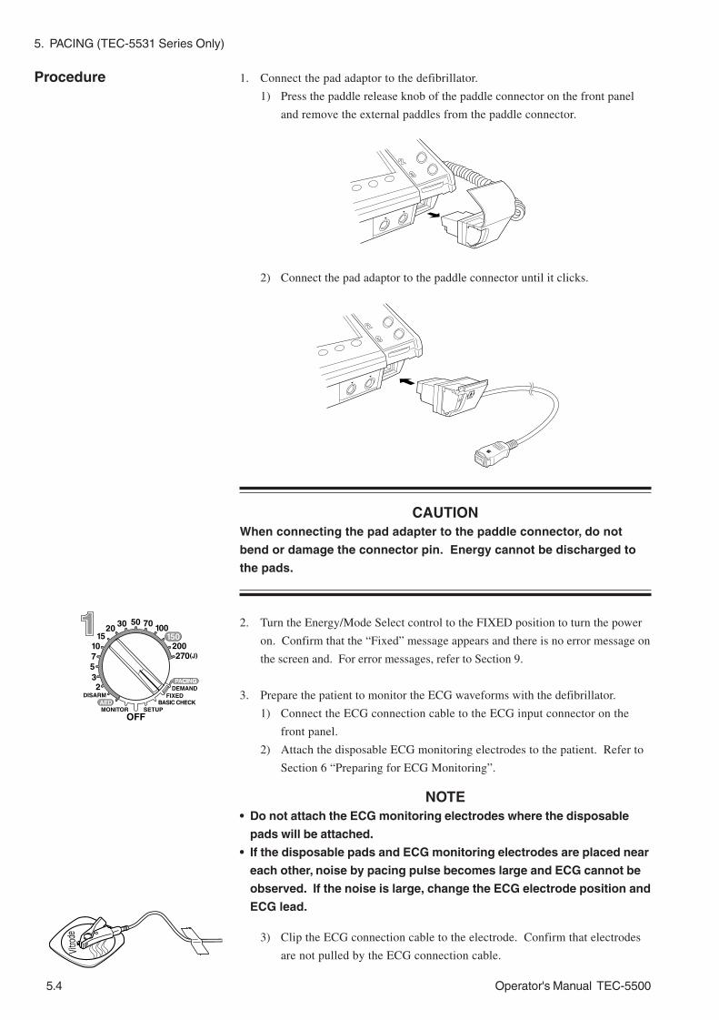
5. PACING (TEC-5531 Series Only)
5.4 Operator's Manual TEC-5500
1. Connect the pad adaptor to the defibrillator.
1) Press the paddle release knob of the paddle connector on the front panel
and remove the external paddles from the paddle connector.
2) Connect the pad adaptor to the paddle connector until it clicks.
CAUTIONWhen connecting the pad adapter to the paddle connector, do not
bend or damage the connector pin. Energy cannot be discharged to
the pads.
2. Turn the Energy/Mode Select control to the FIXED position to turn the power
on. Confirm that the “Fixed” message appears and there is no error message on
the screen and. For error messages, refer to Section 9.
3. Prepare the patient to monitor the ECG waveforms with the defibrillator.
1) Connect the ECG connection cable to the ECG input connector on the
front panel.
2) Attach the disposable ECG monitoring electrodes to the patient. Refer to
Section 6 “Preparing for ECG Monitoring”.
NOTE• Do not attach the ECG monitoring electrodes where the disposable
pads will be attached.
• If the disposable pads and ECG monitoring electrodes are placed near
each other, noise by pacing pulse becomes large and ECG cannot be
observed. If the noise is large, change the ECG electrode position and
ECG lead.
3) Clip the ECG connection cable to the electrode. Confirm that electrodes
are not pulled by the ECG connection cable.
Procedure

5. PACING (TEC-5531 Series Only)
Operator's Manual TEC-5500 5.5
4. Press the ECG lead key to select the lead which has the highest QRS wave.
Usually “II” is selected.
WARNINGNever select “TEST” for the ECG lead. “TEST” is for maintenance and
the waveform displayed on the screen is not the patient’s ECG. If
synchronized cardioversion is performed with the TEST lead, the
discharge is not synchronized with the patient’s QRS.
NOTE• Select a lead so that the whole waveform is displayed on the screen
and the T waveform is not much higher than the QRS waveform.
Otherwise, QRS cannot be recognized correctly.
• If the defibrillator miscounts the narrow width QRS, set “Pacing Pulse
Reject” to OFF on the ECG Setup screen and confirm that QRS is
correctly recognized.
5. Select the pacing rate with the PACING RATE Up/Down key. The selected rate
appears at the lower right corner of the screen.
WARNINGThe pacing rate must be determined by qualified medical personnel
based on the heart rate of the patient in a normal state.
6. Select 0 mA with the PACING OUTPUT Up/Down key. Confirm that the
FIXED mode is selected.
7. Prepare the disposable pads.
WARNING• Failure to follow the warnings below may cause skin burn or
insufficient energy discharge and insufficient pacing current to the
heart.
- Do not reuse disposable pads.
- If the pad package is torn, dispose of the pads and do not use
them.
- Do not use the pads if they are past the expiration date on the
package.
- Use the disposable pads as soon as possible after opening the
package.
- Do not use the disposable pads if the gel has become dry or if the
gel has become abnormal (the gel has become liquid or is coming
off the edges of the pad, etc).
- Do not use the disposable pads if the gel is dark brown or dark
brown gel is on the protective sheet.

5. PACING (TEC-5531 Series Only)
5.6 Operator's Manual TEC-5500
CAUTION• When using the disposable pads for long term ECG monitoring,
replace them every 24 hours. Failure to follow this instruction may
cause insufficient pacing current and insufficient energy discharge to
the heart.
• Do not attach a disposable pad over another pad. It may cause skin
burn on the patient.
• Do not put heavy objects on the disposable pads or bend the pads. If
the pads get damaged or deteriorated, it may cause skin burn on the
patient.
NOTE• Always prepare the second set of disposable pads before pacing. Use
the second set of disposable pads if the gel of the first set of
disposable pads is dry, deteriorated or changes color.
• Before attaching the disposable pads to the patient, clean the skin
where the pads will be attached. If the skin is moist, use a cotton
swab to dry it.
1) To allow firm pad contact with the skin, clean the patient’s chest to remove
oil and dirt, and thoroughly dry the skin. Clip excessive hair, if necessary.
NOTEDo not apply any gel or paste when using disposable pads.
2) Take the disposable pads out of the package and carefully remove the
protective liner from one pad at a time.
WARNING - continued
• If any pad or connector gets wet, replace it with a new one. If a wet
pad or connector is used, it may cause electrical shock.
• When using the disposable pads for long term pacing, replace them
every hour. Failure to follow this warning may cause skin burn or
insufficient energy discharge and pacing current to the heart.

5. PACING (TEC-5531 Series Only)
Operator's Manual TEC-5500 5.7
Anterior-Apex placement
RA: Right side of sternum and below the clavicle
LL: On the level of fifth intercostal space and midaxillary line
3) Attach the pads to the patient’s body, one at a time.
WARNINGFailure to follow the following warnings causes serious skin burn.
• Do not attach the pads over ECG electrode.
• Do not attach pads on the papilla or medicine on the patient’s body.
• Fit the pad closely to the body surface so that current flows uniformly
through the pad. This reduces the required pacing current and pain
and discomfort to the patient.
CAUTIONIf the patient’s body is wet, thoroughly wipe the moisture off the skin
so that the paddles do not short to each other.

5. PACING (TEC-5531 Series Only)
5.8 Operator's Manual TEC-5500
Anterior-Posterior placement
RA: Between left scapula and spine
LL: Fifth middle axial line
WARNINGThe anterior-posterior placement is not suitable for ECG monitoring or
AED analysis. Use this placement only for pacing.
Apex-Posterior placement
RA: Between right scapula and spine
LL: On the level of fifth intercostal space and midaxillary line
WARNINGThe apex-posterior placement is not suitable for ECG monitoring or
AED analysis.

5. PACING (TEC-5531 Series Only)
Operator's Manual TEC-5500 5.9
9. Gradually increase the pacing current with the PACING OUTPUT Up/Down
key. The pacing current appears at the lower right corner of the screen. When a
pacing pulse is output, the PULSE lamp lights and a “ ” mark appears below
the ECG waveforms.
WARNING• Do not touch the patient, pads or connectors during pacing. It may
cause electrical shock.
• During charging or discharging, do not touch the pads or connectors.
Failure to follow this warning causes electrical shock to the operator.
• The pacing current must only be increased by qualified medical
personnel decision.
• Keep the current intensity as low as possible to minimize pain and
discomfort to the patient.
CAUTIONCheck that the pacing pulse is effective by observing ECG on the
screen.
4) Connect the disposable pads to the pad adaptor.
NOTE• Firmly connect the disposable pads to the pad adaptor until the
connector of the disposable pads clicks.
• When the “Change disposable pads” message appears, the pads may
be faulty. Replace them with new ones. If the message still appears,
stop using the defibrillator and use a different defibrillator.
8. Press the START/STOP key to start pacing. The ”Now Pacing” message
appears.

5. PACING (TEC-5531 Series Only)
5.10 Operator's Manual TEC-5500
NOTE• When the pacing intensity is set to 0 mA, the PULSE lamp does not
light.
• Pacing is not performed for 3 seconds after the START/STOP key is
pressed.
• When the pacing intensity is set to under 10 mA, the “Pacing
stopped. (paddle disconnected)” message may not be displayed.
Always check the pacing effect on the screen.
To stop pacing, press the START/STOP key or select 0 mA with the PACING
OUTPUT Up/Down key.
NOTEWhen you stop pacing by selecting 0 mA with the PACING OUTPUT Up/
Down key, pacing restarts when you select another intensity with the
PACING OUTPUT Up/Down key.
10. Turn the Energy/Mode Select control to the OFF position. Press the paddle
release knob of the paddle connector on the front panel and remove the pad
adaptor from the paddle connector. Dispose of the disposable pads and the
electrodes too.
NOTEWhile the “Shutdown NOW” message is displayed on the screen, do not
disconnect the power cord from the defibrillator or AC outlet and do not
remove the battery pack from the defibrillator. Otherwise, the internal
data may be damaged.

5. PACING (TEC-5531 Series Only)
Operator's Manual TEC-5500 5.11
Pacing in DEMAND mode
Information on the PacingScreen in DEMAND Mode
Pacing pulse output point
QRS sync markHeart rate
Demand pacing mode
Pacing rate
Pacing current
ECG sensitivity
ECG lead
AC power operation
QRS wave detection point
Spontaneous ECG
The following information can be displayed on the pacing screen in DEMAND
mode.
This is the pacing screen in DEMAND mode which appears when neither SpO2 nor
CO2 is monitored.

5. PACING (TEC-5531 Series Only)
5.12 Operator's Manual TEC-5500
WARNINGConfirm that there is no noise on the ECG. Noise may be
misrecognized as QRS and discharge might not synchronize with the
patient’s QRS.
1. Connect the pad adaptor to the defibrillator.
1) Press the paddle release knob of the paddle connector on the right panel
and remove the external paddles from the paddle connector.
2) Connect the pad adaptor to the paddle connector until it clicks.
CAUTIONWhen connecting the pad adapter to the paddle connector, do not
bend or damage the connector pin. Energy cannot be discharged to
the pads.
2. Turn the Energy/Mode Select control to the DEMAND position to turn the
power on. Confirm that the “Demand” appears and that there is no error
message on the screen. For error messages, refer to Section 9.
3. Prepare the patient to monitor the ECG waveforms with the defibrillator.
1) Connect the ECG connection cable to the ECG input connector on the
front panel.
2) Attach the disposable ECG monitoring electrodes to the patient. Refer to
Section 6 “Preparing for ECG Monitoring”.
Procedure
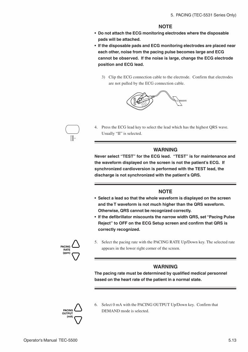
5. PACING (TEC-5531 Series Only)
Operator's Manual TEC-5500 5.13
NOTE• Do not attach the ECG monitoring electrodes where the disposable
pads will be attached.
• If the disposable pads and ECG monitoring electrodes are placed near
each other, noise from the pacing pulse becomes large and ECG
cannot be observed. If the noise is large, change the ECG electrode
position and ECG lead.
3) Clip the ECG connection cable to the electrode. Confirm that electrodes
are not pulled by the ECG connection cable.
4. Press the ECG lead key to select the lead which has the highest QRS wave.
Usually “II” is selected.
WARNINGNever select “TEST” for the ECG lead. “TEST” is for maintenance and
the waveform displayed on the screen is not the patient’s ECG. If
synchronized cardioversion is performed with the TEST lead, the
discharge is not synchronized with the patient’s QRS.
NOTE• Select a lead so that the whole waveform is displayed on the screen
and the T waveform is not much higher than the QRS waveform.
Otherwise, QRS cannot be recognized correctly.
• If the defibrillator miscounts the narrow width QRS, set “Pacing Pulse
Reject” to OFF on the ECG Setup screen and confirm that QRS is
correctly recognized.
5. Select the pacing rate with the PACING RATE Up/Down key. The selected rate
appears in the lower right corner of the screen.
WARNINGThe pacing rate must be determined by qualified medical personnel
based on the heart rate of the patient in a normal state.
6. Select 0 mA with the PACING OUTPUT Up/Down key. Confirm that
DEMAND mode is selected.

5. PACING (TEC-5531 Series Only)
5.14 Operator's Manual TEC-5500
7. Prepare the disposable pads.
WARNING• Failure to follow the warnings below may cause skin burn or
insufficient energy discharge and insufficient pacing current to the
heart.
- Do not reuse disposable pads.
- If the pad package is torn, dispose of the pads and do not use
them.
- Do not use the pads if they are past the expiration date on the
package.
- Use the disposable pads as soon as possible after opening the
package.
- Do not use the disposable pads if the gel has become dry or if the
gel has become abnormal (the gel has become liquid or is coming
off the edges of the pad, etc).
- Do not use the disposable pads if the gel is dark brown or dark
brown gel is on the protective sheet.
• If any pad or connector gets wet, replace it with a new one. If a wet
pad or connector is used, it may cause electrical shock.
• When using the disposable pads for long term pacing, replace them
every hour. Failure to follow this warning may cause skin burn or
insufficient energy discharge and pacing current to the heart.
CAUTION• When using the disposable pads for long term ECG monitoring,
replace them every 24 hours. Failure to follow this instruction may
cause insufficient pacing current and insufficient energy discharge to
the heart.
• Do not attach a disposable pad over another pad. It may cause skin
burn on the patient.
• Do not put heavy objects on the disposable pads or bend the pads. If
the pads get damaged or deteriorated, it may cause skin burn on the
patient.
NOTE• Always prepare the second set of disposable pads before pacing. Use
the second set of disposable pads if the gel of the first set of
disposable pads is dry, deteriorated or changes color.
• Before attaching the disposable pads to the patient, clean the skin
where the pads will be attached. If the skin is moist, use a cotton
swab to dry it.
1) To allow firm pad contact with the skin, clean the patient’s chest to remove
oil and dirt, and thoroughly dry the skin. Clip excessive hair, if necessary.
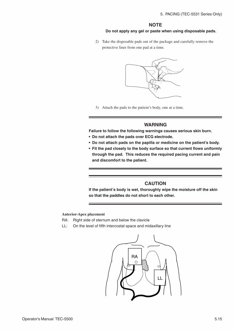
5. PACING (TEC-5531 Series Only)
Operator's Manual TEC-5500 5.15
Anterior-Apex placement
RA: Right side of sternum and below the clavicle
LL: On the level of fifth intercostal space and midaxillary line
2) Take the disposable pads out of the package and carefully remove the
protective liner from one pad at a time.
NOTEDo not apply any gel or paste when using disposable pads.
3) Attach the pads to the patient’s body, one at a time.
WARNINGFailure to follow the following warnings causes serious skin burn.
• Do not attach the pads over ECG electrode.
• Do not attach pads on the papilla or medicine on the patient’s body.
• Fit the pad closely to the body surface so that current flows uniformly
through the pad. This reduces the required pacing current and pain
and discomfort to the patient.
CAUTIONIf the patient’s body is wet, thoroughly wipe the moisture off the skin
so that the paddles do not short to each other.

5. PACING (TEC-5531 Series Only)
5.16 Operator's Manual TEC-5500
Anterior-Posterior placement
RA: Between left scapula and spine
LL: Fifth middle axial line
Apex-Posterior placement
RA: Between right scapula and spine
LL: On the level of fifth intercostal space and midaxillary line
WARNINGThe anterior-posterior placement is not suitable for ECG monitoring or
AED analysis. Use this placement only for pacing.
WARNINGThe apex-posterior placement is not suitable for ECG monitoring or
AED analysis.

5. PACING (TEC-5531 Series Only)
Operator's Manual TEC-5500 5.17
4) Connect the disposable pads to the pad adaptor.
NOTE• Firmly connect the disposable pads to the pad adaptor until the
connector of the disposable pads clicks.
• When the “Change disposable pads” message appears, the pads may
be faulty. Replace them with new ones. If the message still appears,
stop using the defibrillator and use a different defibrillator.
8. Check that the “ ” mark appears on every QRS wave.
The “ ” mark indicates that the defibrillator detects the QRS wave. If the mark
does not appear:
- Change the amplitude of the ECG waveforms with the ECG sensitivity key.
- Change the ECG lead with the ECG lead key.
- Change the electrode position.
9. Press the START/STOP key to start pacing. The “Now Pacing” message
appears.
10. Gradually increase the pacing current with the PACING OUTPUT Up/Down
key until QRS by pacing appears on the screen. The pacing current appears in
the lower right corner of the screen. When a pacing pulse is output, the PULSE
lamp lights and a “ ” mark appears below the ECG waveforms.
WARNING• Do not touch the patient during pacing. Failure to follow this warning
may cause electrical shock.
• During charging or discharging, do not touch the pads or connectors.
Failure to follow this warning causes electrical shock to the operator.
• Do not change the sensitivity or ECG lead setting after pacing is
started. If one of these settings is changed, the pacing stops for 3
seconds. Failure to follow this warning may cause serious heart
attack.
• The pacing current must only be increased by qualified medical
personnel decision.

5. PACING (TEC-5531 Series Only)
5.18 Operator's Manual TEC-5500
WARNING continued• Keep the current intensity as low as possible to minimize pain and
discomfort to the patient.
• No QRS wave is detected:
- For 240 ms after the pacing pulse is output, if the pacing rate is set
to 100 ppm or more.
- For 350 ms after the pacing pulse is output, if the pacing rate is set
to 90 ppm or less.
CAUTIONCheck that the pacing pulse is effective by observing ECG on the
screen.
NOTE• The paced QRS wave may not be counted correctly.
• When the pacing intensity is set to 0 mA, the PULSE lamp does not
light.
• Pacing is not performed for 3 seconds after the START/STOP key is
pressed.
• When the pacing intensity is set to under 10 mA, the “Pacing stopped.
(paddle disconnected)” message may not be displayed. Always check
the pacing effect on the screen.
To stop pacing, press the START/STOP key or select 0 mA with the PACING
OUTPUT Up/Down key.
NOTEWhen you stop pacing by selecting 0 mA with the PACING OUTPUT Up/
Down key, pacing restarts when you select another intensity with the
PACING OUTPUT Up/Down key.
11. Turn the Energy/Mode Select control to the OFF position. Press the paddle
release knob of the paddle connector on the front panel and remove the pad
adaptor from the paddle connector. Dispose of the disposable pads and the
electrodes.
NOTEWhile the “Shutdown NOW” message is displayed on the screen, do not
disconnect the power cord from the defibrillator or AC outlet and do not
remove the battery pack from the defibrillator. Otherwise, the internal
data may be damaged.
Operator's Manual TEC-5500 6C.1
Section 6 Monitoring
General .............................................................................................................................6.0.1
Displaying the Monitoring Screen ...........................................................................6.0.1
Screen Examples ...................................................................................................6.0.1
ECG Monitoring
Preparing for ECG Monitoring ...........................................................................................6.1.2
Preparation Flowchart ............................................................................................6.1.2
Selecting a Lead ....................................................................................................6.1.2
Number of Electrodes and Measuring Leads ..........................................................6.1.3
Electrode Position ..................................................................................................6.1.3
3 Electrode Leads ........................................................................................6.1.3
5 Electrode Leads ........................................................................................6.1.4
Selecting Electrodes and Lead ...............................................................................6.1.5
Types of Electrodes and Lead ......................................................................6.1.5
Connecting the ECG Connection Cable or the JC-762V/JC763V Connection Cable to
the Defibrillator .......................................................................................................6.1.6
Connecting the ECG Connection Cable to the Defibrillator ...........................6.1.6
Connecting the JC-762V/JC763V Connection Cable to the Defibrillator .......6.1.6
Attaching Disposable ECG Electrodes to the Patient ............................................. 6.1.7
Monitoring ECG with Disposable Pads ...................................................................6.1.8
Monitoring ECG ................................................................................................................6.1.9
ECG Information on the Monitoring Screen ............................................................6.1.9
Selecting an ECG Lead .................................................................................................. 6.1.10
Selecting ECG Sensitivity .............................................................................................. 6.1.11
AUTO ......................................................................................................... 6.1.11
Changing ECG Settings ................................................................................................. 6.1.12
Changing Settings on the ECG Setup Screen ...................................................... 6.1.12
Turning the AC Hum Filter On/Off ......................................................................... 6.1.13
Changing the Time Constant Setting .................................................................... 6.1.14
Turning Pacing Pulse Rejection On/Off ................................................................. 6.1.15
Changing Heart Rate Upper/Lower Limit ............................................................... 6.1.16
Changing Settings on the QRS Setup Screen ...................................................... 6.1.17
Changing QRS Sync Sound Volume..................................................................... 6.1.18
Changing QRS Sync Sound Source ..................................................................... 6.1.18

6C.2 Operator's Manual TEC-5500
Turning the VF/VT Alarm On or Off ...................................................................... 6.1.19
Use with an Electrosurgical Unit ..................................................................................... 6.1.20
SpO2 monitoring
General .............................................................................................................................6.2.1
Preparing for SpO2 Monitoring ........................................................................................... 6.2.3
Preparation Flowchart ............................................................................................. 6.2.3
Selecting a Probe ................................................................................................... 6.2.3
Reusable Probes .......................................................................................... 6.2.4
Disposable Probes ....................................................................................... 6.2.5
Attaching the Probe to the Patient ......................................................................... 6.2.6
Connecting Probe to Defibrillator ............................................................................ 6.2.6
Monitoring SpO2
................................................................................................................................................................................................... 6.2.8
SpO2 Information on the Monitoring Screen ............................................................ 6.2.8
Changing SpO2 Settings ................................................................................................... 6.2.9
Changing Settings on the SpO2 Setup Screen........................................................ 6.2.9
Changing the Pulse Waveform Sensitivity ............................................................. 6.2.10
Selecting Sync Sound Pitch ................................................................................ 6.2.11
Changing the Pulse Rate Alarm Limits ................................................................ 6.2.12
Changing the SpO2 Alarm Limits .......................................................................... 6.2.13
Changing QRS Sync Sound Volume .................................................................... 6.2.13
Changing QRS Sync Sound Source ..................................................................... 6.2.13
CO2 monitoring
General .............................................................................................................................6.3.1
CO2 Sensor Kit ....................................................................................................... 6.3.3
Preparing for CO2 Monitoring ............................................................................................ 6.3.6
Preparation Flowchart ............................................................................................. 6.3.6
Connecting the CO2 Sensor Kit to the Defibrillator .................................................. 6.3.6
Monitoring CO2
...................................................................................................................................................................................................... 6.3.7
CO2 Information on the Monitoring Screen .............................................................. 6.3.7
Changing CO2 Settings..................................................................................................... 6.3.8
Changing Settings on the CO2 Setup Screen ......................................................... 6.3.8
Changing the CO2 Scale ......................................................................................... 6.3.9
Changing the etCO2 Alarm Limits ......................................................................... 6.3.10
Changing the Respiration Rate Alarm Limits ........................................................ 6.3.11
Changing the APNEA Alarm Limit ......................................................................... 6.3.12
Inspection of Measuring Accuracy .................................................................................. 6.3.13
Daily Inspection of Measuring Accuracy ............................................................... 6.3.13
Inspection of Measuring Accuracy (Precise Method) ............................................ 6.3.13
Checking Procedure ................................................................................... 6.3.14

6. MONITORING
Operator's Manual TEC-5500 6.0.1
ECG, SpO2 and CO2 can be monitored with this defibrillator. When monitoring
starts, waveforms, measurement value of each parameter and/or bar graphs for CO2
or SpO2. are displayed on the screen.
To display the monitoring screen, turn the Energy/Mode Select control to the
MONITOR position. You can select the display parameters in the Setup - Date/
Screen screen.
General
Displaying the MonitoringScreen
Screen Examples
Heart rate ECG lead
QRS sync markECG sensitivity
ECG waveform
SpO2 value
SpO2 waveform
Pulse rate
CO2 value Respiration rateCO2 bar graph
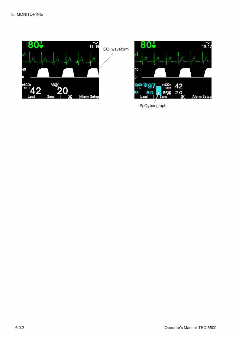
6. MONITORING
6.0.2 Operator's Manual TEC-5500
CO2 waveform
SpO2 bar graph

Operator's Manual TEC-5500 6.1C.1
ECG Monitoring
Preparing for ECG Monitoring ...........................................................................................6.1.2
Preparation Flowchart ............................................................................................6.1.2
Selecting a Lead ....................................................................................................6.1.2
Number of Electrodes and Measuring Leads ..........................................................6.1.3
Electrode Position ..................................................................................................6.1.3
3 Electrode Leads ........................................................................................6.1.3
5 Electrode Leads ........................................................................................6.1.4
Selecting Electrodes and Lead ...............................................................................6.1.5
Types of Electrodes and Lead ......................................................................6.1.5
Connecting the ECG Connection Cable or the JC-762V/JC763V Connection Cable to
the Defibrillator .......................................................................................................6.1.6
Connecting the ECG Connection Cable to the Defibrillator ...........................6.1.6
Connecting the JC-762V/JC763V Connection Cable to the Defibrillator .......6.1.6
Attaching Disposable ECG Electrodes to the Patient ............................................. 6.1.7
Monitoring ECG with Disposable Pads ...................................................................6.1.8
Monitoring ECG ................................................................................................................6.1.9
ECG Information on the Monitoring Screen ............................................................6.1.9
Selecting an ECG Lead .................................................................................................. 6.1.10
Selecting ECG Sensitivity .............................................................................................. 6.1.11
AUTO ......................................................................................................... 6.1.11
Changing ECG Settings ................................................................................................. 6.1.12
Changing Settings on the ECG Setup Screen ...................................................... 6.1.12
Turning the AC Hum Filter On/Off ......................................................................... 6.1.13
Changing the Time Constant Setting .................................................................... 6.1.14
Turning Pacing Pulse Rejection On/Off ................................................................. 6.1.15
Changing Heart Rate Upper/Lower Limit ............................................................... 6.1.16
Changing Settings on the QRS Setup Screen ...................................................... 6.1.17
Changing QRS Sync Sound Volume..................................................................... 6.1.18
Changing QRS Sync Sound Source ..................................................................... 6.1.18
Turning the VF/VT Alarm On or Off ...................................................................... 6.1.19
Use with an Electrosurgical Unit ..................................................................................... 6.1.20

6.1C.2 Operator's Manual TEC-5500
This page is intentionally left blank.

6. MONITORING
Operator's Manual TEC-5500 6.1.1
ECG is monitored by attaching disposable electrodes to the patient and connecting
to the ECG input connector on the front panel. ECG is also monitored by attaching
disposable pads to the patient and selecting PADDLE for the ECG lead. ECG
waveform and heart rate are displayed.

6. MONITORING
6.1.2 Operator's Manual TEC-5500
Preparing for ECG Monitoring
Preparation Flowchart
Selecting a Lead
P T1
QRS1
T2
QRS2
1. Select the disposable ECG electrode and ECG connection cable.
2. Connect the ECG connection cable to the ECG input connector on the
defibrillator.
3. Attach the disposable ECG electrodes to the patient and attach the ECG
connection cable to the electrodes.
4. Monitoring starts. Set necessary settings.
For handling accessories after use, refer to Section 10.
NOTEFollow the physician’s instructions for lead position when available.
Select the optimum lead according to the following guidelines:
1) Select the lead with the highest QRS wave amplitude and least difference
in amplitude compared with a VPC or pacing pulse.
0.5 ≤ QRS1/QRS2 ≤ 2
2) Select a lead with less than 0.2 mV amplitude of the P-wave. (with the
sensitivity ×1 and P amplitude is less than 2 mm on the screen)
P ≤ 0.2 mV
3) Select a lead with a T-wave amplitude which is less than one-third of the
QRS wave.
T1 ≤ 1/3QRS1, T2 ≤ 1/3QRS2

Operator's Manual TEC-5500 6.1. 3
6. MONITORING
Number of Electrodes andMeasuring Leads
Electrode Position
The leads which can be monitored differ according to the type of ECG connection
cable or electrode lead and number of electrodes used.
NOTE• When attaching ECG electrodes for synchronized cardioversion or
external pacing, avoid positions where paddles or pads are placed.
• When electrodes cannot be attached to the positions shown below
(for example because of chest operation), a relatively stable ECG
waveform can be obtained by attaching electrodes on both shoulder
joints.
3 Electrode Leads
Electrode Position
Lead Connection
Lead I Lead II Lead III
R/RA L/LA
F/LL
R/RAR/RA L/LAL/LA
F/LLF/LL
R/RA L/LA
F/LL
Symbol Lead Color (Clip Color) Electrode PositionR
RARed (Red-beige)White (White-beige) Right infraclavicular fossa
LLA
Yellow (Yellow-beige)Black (Black-beige) Left infraclavicular fossa
FLL
Green (Green-beige)Red (Red-beige)
Lowest rib on the left anterior axillaryline
Lead Features
3 electrodes I, II, III Can measure at the thoracic wall.
5 electrodesI, II, III, aVR, aVL, aVF, V(V is one of V1 to V6)
Similar to the standard 12 lead.
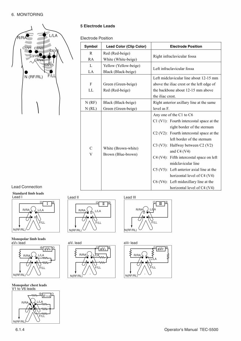
6. MONITORING
6.1.4 Operator's Manual TEC-5500
Standard limb leads
Monopolar limb leads
Monopolar chest leads
Lead I Lead II Lead III
aVR lead aVL lead aVF lead
V1 to V6 leads
to
R/RA
R/RA
R/RA R/RA R/RA
R/RAR/RAL/LA
L/LA
L/LAL/LAL/LA
L/LAL/LA
F/LL
F/LL
F/LLF/LL F/LL
F/LLF/LL
N(RF/RL)
N(RF/RL)
N(RF/RL) N(RF/RL) N(RF/RL)
N(RF/RL)N(RF/RL)
Lead Connection
5 Electrode Leads
Electrode PositionR/RA L/LA
N (RF/RL) F/LL
C1/V1 C2/V2
C3/V3C4/V4
C5/V5
C6/V6Symbol Lead Color (Clip Color) Electrode Position
R RA
Red (Red-beige) White (White-beige)
Right infraclavicular fossa
L LA
Yellow (Yellow-beige) Black (Black-beige)
Left infraclavicular fossa
F LL
Green (Green-beige) Red (Red-beige)
Left midclavicular line about 12-15 mm above the iliac crest or the left edge of the backbone about 12-15 mm above the iliac crest.
N (RF) N (RL)
Black (Black-beige) Green (Green-beige)
Right anterior axillary line at the same level as F.
C V
White (Brown-white) Brown (Blue-brown)
Any one of the C1 to C6 C1 (V1): Fourth intercostal space at the
right border of the sternum C2 (V2): Fourth intercostal space at the
left border of the sternum C3 (V3): Halfway between C2 (V2)
and C4 (V4) C4 (V4): Fifth intercostal space on left
midclavicular line C5 (V5): Left anterior axial line at the
horizontal level of C4 (V4) C6 (V6): Left midaxillary line at the
horizontal level of C4 (V4)

6. MONITORING
Operator's Manual TEC-5500 6.1.5
Selecting Electrodes andLead
Types of Electrodes and Lead
Select the appropriate disposable ECG electrodes and ECG connection cable or
electrode lead according to the number of electrodes (lead).
WARNINGWhen using a defibrillator together with the monitor, use Ag/AgCl
electrodes. Other types of electrodes, stainless steel in particular, will
adversely affect the ECG waveform by slowing the baseline recovery
on the monitor and result in no monitoring immediately following
defibrillation.
CAUTIONOnly use Nihon Kohden specified parts and accessories. When other
parts or accessories are used, the defibrillator heats up and may be
damaged, and monitoring stops.
No. of Electrodes Disposable
Electrodes
ECG connection cable or
Electrode Lead Connection cable
ECG connection cable BC-763V
Not necessary
3 (I, II, III)
Electrode lead BR-018P, BR-019P, BR-024P, BR-033P, BR-034P, BR-903P
JC-762V/763V connection cable Example: JC-762V
ECG connection cable BC-765V
Not necessary
5 (I, II, III, aVR, aVL, aVF, any one of the V1 to V6)
Vitrode C-150 (Recommended)
Electrode lead BR-020P, BR-021P, BR-026P
JC-762V connection cable

6. MONITORING
6.1.6 Operator's Manual TEC-5500
Attaching Disposable ECGElectrodes to the Patient
Connecting the ECGConnection Cable or theJC-762V/JC763VConnection Cable to theDefibrillator
Connecting the ECG Connection Cable to the Defibrillator
Connect the ECG connection cable to the ECG input connector on the front panel
of the defibrillator.
Connecting the JC-762V/JC763V Connection Cable to the Defibrillator
1. Connect electrode leads to the connector of the JC-762V or JC-763V
connection cable.
2. Connect the JC-762V or JC-763V connection cable to the ECG input
connector on the front panel of the defibrillator.
CAUTIONDo not reuse disposable items.
NOTE• To maintain good contact between the electrode and skin, check that
the paste of the disposable ECG electrode is not dry.
• When contact of the disposable ECG electrode becomes poor,
replace the electrode with a new one immediately. Otherwise,
contact impedance between the skin and electrode increases and the
correct ECG cannot be obtained.
• If the contact is bad before the expiration date on the package,
replace the electrode with a new one.
1. Shave excess hair. With a piece of cotton pad moistened with alcohol, clean
the patient’s skin where the electrodes should be mounted. Avoid wrinkled or
uneven skin areas. Wipe off the alcohol with a dry cotton pad.

6. MONITORING
Operator's Manual TEC-5500 6.1.7
Extra length
NOTETo obtain a stable ECG waveform rub the skin with “Skinpure” skin
preparation gel.
2. Open the disposable electrode package and take out the electrode.
3. Remove the gel cover from the electrode. Be careful not to touch the adhesive
side.
4. Attach the disposable ECG electrode to the previously cleaned skin. Avoid
wrinkled and uneven skin areas.
NOTEIf the contact becomes bad because of sweat or body movement,
replace the electrode with a new one.
5. Clip the electrode lead or ECG connection cable onto the electrode.
NOTECheck that electrodes are not pulled by the ECG connection cable or
electrode lead.
6. Fasten the electrode lead to the skin with surgical tape with an extra length of
wire between the tape and the electrode. This prevents body movement from
moving the electrode lead.
Monitoring ECG withDisposable Pads
You can monitor patient’s ECG using the disposable pads instead of ECG
monitoring electrodes. However, 3 electrode lead ECG and 5 electrode lead ECG
are not available with disposable pads.
For connecting the pad adaptor to the defibrillator, attaching the disposable pads to
the patient and attachment site, refer to Section 4.
WARNING• When using an ESU, use this defibrillator only in the MONITOR mode
and use the ECG electrodes for monitoring. Do not monitor ECG with
disposable pads, external paddles or internal paddles. If ECG is
monitored with pads or paddles, high frequency energy from the
ESU causes abnormal current to flow in the patient and unexpected
discharge. This may damage the defibrillator.
• Failure to follow the warnings below may cause skin burn or
insufficient energy discharge and insufficient pacing current to the
heart.
- Do not reuse disposable pads.
- If the pad package is torn, dispose of the pads and do not use
them.
- Do not use the pads if they are past the expiration date on the
package.

6. MONITORING
6.1.8 Operator's Manual TEC-5500
WARNING - continued
- Use the disposable pads as soon as possible after opening the
package.
- Do not use the disposable pads if the gel has become dry or if the
gel has become abnormal (the gel has become liquid or is coming
off the edges of the pad, etc).
- Do not use the disposable pads if the gel is dark brown or dark
brown gel is on the protective sheet.
• If any pad or connector gets wet, replace it with a new one. If a wet
pad or connector is used, it may cause electrical shock.
CAUTION• When using the disposable pads for long term ECG monitoring,
replace them every 24 hours. Failure to follow this instruction may
cause insufficient pacing current and insufficient energy discharge to
the heart.
• Do not attach a disposable pad over another pad. It may cause skin
burn on the patient.
• Do not put heavy objects on the disposable pads or bend the pads. If
the pads get damaged or deteriorated, it may cause skin burn on the
patient.
NOTE• Follow all disposable pad labeling instructions.
• Before attaching the disposable pads to the patient, clean the skin
where the pads will be attached. If the skin is moist, use a cotton
swab to dry it.

6. MONITORING
Operator's Manual TEC-5500 6.1.9
Monitoring ECG
ECG Information on theMonitoring Screen
Heart rate
ECG waveform
Sensitivity
ECG Lead
When electrodes are attached to the patient and cables are connected properly, ECG
appears on the screen.
CAUTIONWhen the “Check ECG Electrodes” message is displayed, ECG is not
monitored properly and the ECG alarm does not function. Check the
electrode, electrode leads and connection cord, and if necessary,
replace with new ones.
QRS sync mark

6. MONITORING
6.1.10 Operator's Manual TEC-5500
Selecting an ECG Lead
Select the lead for ECG waveform. The leads which can be selected depend on the
instrument mode (defibrillation mode, AED mode, PACING mode, MONITOR
mode) and the number of electrodes used.
Press the ECG lead key to change the ECG lead. When the key is pressed, the ECG
lead changes as below.
NOTEWhen using 5 electrode leads, select 5 leads at ECG lead on the
System Setup screen.
In defibrillation or MONITOR mode
3 electrode leads: PADDLE → I → II → III → AUX* → (TEST)*** →PADDLE...
5 electrode leads: PADDLE → I → II → III → aVR → aVL → aVF → V** →AUX* → (TEST)*** → PADDLE...
In PACING mode
3 electrode leads: I → II → III → (TEST)*** → I...
5 electrode leads: I → II → III → aVR → aVL → aVF → V** → (TEST)*** →I...
In AED mode
3 electrode leads: PADDLE only
5 electrode leads: PADDLE only
* AUX displays ECG waveform from the JC-761V External ECG cable. In 5
electrode leads, AUX (external ECG input) displays the same ECG waveform
as V.
** V is one of the chest leads V1 to V6.
*** When you set “Test lead” to OFF on the System Setup screen, TEST cannot
be selected.
NOTE• With the PADDLE lead, a patient with an implanted pacemaker cannot
be monitored correctly.
• Select a lead so that the whole waveform is displayed on the screen
and the T waveform is not much higher than the QRS waveform.
Otherwise, QRS cannot be recognized correctly.
• When the defibrillator miscounts the narrow width QRS, set “Pacing
Pulse Reject” to OFF on the ECG Setup screen and confirm that QRS
is correctly recognized.

6. MONITORING
Operator's Manual TEC-5500 6.1.11
(For example)
AG × 2 in MONITOR mode
screen changes to defibrillation screen.
× 2 in defibrillation mode
screen changes to MONITOR mode
× 2 in MONITOR mode
(the sensitivity does not automatically return to AUTO.)
Selecting ECG Sensitivity
Select the sensitivity of the ECG waveform to be monitored. This sensitivity is
applied to the QRS detection sensitivity. For stable QRS detection, select the
sensitivity so that the amplitude of the QRS is larger than 1 cm.
Setting range: ×1/4, ×1/2, ×1 (default setting), ×2, ×4, AUTO*
* AUTO can only be selected in monitoring mode.
Press the ECG Sensitivity key on the front panel to change the ECG sensitivity.
When the key is pressed, sensitivity changes as below.
Monitor mode: ×1/4 → ×1/2 → ×1 → ×2 → ×4 → AUTO → ×1/4
Defibrillation, pacing, AED, paddle lead mode:
×1/4 → ×1/2 → ×1 → ×2 → ×4 → ×1/4
AUTO
When you select AUTO sensitivity, the appropriate sensitivity is automatically
selected. The selected sensitivity is displayed at the left upper of the screen.
NOTEAUTO sensitivity is not possible when there is noise.
QRS waveform amplitude and selected sensitivity
When AUTO is selected in MONITOR mode and the screen changes to another
screen, the sensitivity is not AUTO any more.
QRS amplitude AUTO sensitivity Display
< 5 mm 4 AG ×4 < 10 mm 2 AG ×2 < 20 mm 1 AG ×1 < 40 mm 1/2 AG ×1/2 more than 40 mm 1/4 AG ×1/4

6. MONITORING
6.1.12 Operator's Manual TEC-5500
Changing ECG Settings
Changing Settings on theECG Setup Screen
1. Turn the Energy/Mode Select control to the SETUP position. The Setup Menu
screen appears.
2. Select “ECG Setup” with the Item ↓ or Item ↑ key and press the SET key.
The ECG Setup screen appears.
The following settings can be changed for ECG monitoring.
Item Description (default settings is underlined)
AC hum filter When set to “ON”, the hum filter automatically reduces AC interference from the ECG
ON, OFF
Time Constant Set the time constant for ECG display in MONITOR mode.
3.2s, 0.32s
Pacing Pulse Reject When set to “ON”, it allows correct heart rate counting when the patient has an implanted pacemaker.
ON, OFF
HR alarm Set the upper and lower limit of the heart rate alarm.
Upper: 20 to 300, OFF (140) Lower: OFF, 15 to 295 (40)
QRS Volume Set the QRS sync sound volume. 0 to 4 (3) QRS Sound Select the source of the QRS sync
sound. ECG, SpO2
VF/VT Alarm Select whether or not to detect VF/VT. ON, OFF

6. MONITORING
Operator's Manual TEC-5500 6.1.13
Turning the AC Hum FilterOn/Off
3. Press the Item key to select the item. When you press the key, selected item
switches.
4. Press the ↓ or ↑ key to change settings. Repeat steps 3 and 4 to set all items.
5. Turn the Energy/Mode Select control to the MONITOR position to return to
the monitoring screen appears.
When “ON” is selected, the hum filter automatically reduces AC interference from
the ECG. This filter also prevents ECG baseline drift in MONITOR mode.
ON AC interference is reduced. Select ON when there is much AC interference
or when using an electrosurgical unit. (Default setting: ON)
OFF: AC interference is not reduced. Select when you want to monitor unfiltered
waveforms for example when examining a QRS change in ECG.
NOTE• The AC hum filter is fixed to ON when PADDLE is selected as an ECG
source lead.
• When the hum filter is set to ON, some QRS waveforms are distorted
greatly.
1. On the ECG Setup screen, select AC hum filter with the Item key.
2. Select ON or OFF with the ↓ or ↑ key.

6. MONITORING
6.1.14 Operator's Manual TEC-5500
Changing the TimeConstant Setting
When ECG baseline drift is large, set the Time constant to 3.2 s (Default setting:
0.32 s).
NOTE• The Time Constant is fixed to 0.32 s when PADDLE is selected as an
ECG source lead.
• The Time Constant is fixed to 3.2 s when AUX is selected as a ECG
source lead.
1. On the ECG Setup screen, select Time Constant with the Item key.
2. Select 0.32 s or 3.2 s or with the ↓ or ↑ key.

6. MONITORING
Operator's Manual TEC-5500 6.1.15
Turning Pacing PulseRejection On/Off
* Pacing failure is a state wherepacing spike is output butventricular or atrial reaction doesnot occur.
This setting selects whether or not to reject pacemaker spike counting and allow
correct heart rate counting when monitoring the patient who has an implanted
cardiac pacemaker.
ON: Reject pacemaker spike counting and allow correct heart rate counting.
Select ON when the patient has an implanted cardiac pacemaker. When the
defibrillator detects an implanted pacemaker pulse output, “ ” is displayed
below the waveform.
OFF: Pacing pulses are not detected. Select OFF when you monitor a premature
baby or infant and the defibrillator miscounts the narrow width QRS.
(Default setting: OFF)
WARNING• Keep pacemaker patients under close observation. The pacemaker
rate may be counted during cardiac arrest and certain arrhythmias.Do not rely only on heart rate alarms and the displayed heart rate.
• With the pacing pulse rejection ON, narrow width QRS of apremature baby or infant cannot be detected correctly and thedefibrillator may miscount QRS. In this case, set the pacing pulserejection to OFF.
• Turn the pacing pulse rejection to OFF when monitoring a child.With the pacing pulse rejection ON, narrow width QRS of a childcannot be detected correctly and the defibrillator may miscount
QRS.
CAUTIONTurn the pacing pulse rejection to On when monitoring a pacemakerpatient. Otherwise QRS and pacemaker spike might not be
distinguished and pacing failure might not be recognized.
NOTEPADDLE lead has low frequency characteristics. Therefore, when you
monitor a patient with an implanted pacemaker in PADDLE lead, a
pacemaker spike may be displayed like a QRS.
1. On the ECG Setup screen, select Pacing Pulse Reject with the Item key.
2. Select ON or OFF with the ↓ or ↑ key.

6. MONITORING
6.1.16 Operator's Manual TEC-5500
Set the upper and lower limit of the heart rate alarm.
Setting range:
Changing Heart RateUpper/Lower Limit
NOTEIf you increase the upper limit over 300, the upper limit becomes OFF.
If you decrease the lower limit below 15, the lower limit becomes OFF.
CAUTIONWhen the upper or lower alarm limit is turned off, there will be no heart
rate upper or lower alarm for that limit.
1. On the ECG Setup screen, select the heart rate upper limit or lower limit of the
heart rate alarm with the Item key.
The arrow in the HR bar graph indicates the current heart rate.
2. Set the upper or lower limit with the ↓ or ↑ key.
Item Range Step Default setting
Upper 20 to 300, OFF 5 140 HR (heart rate) beat/min
Lower OFF, 15 to 295 5 40

6. MONITORING
Operator's Manual TEC-5500 6.1.17
Changing Settings on theQRS Setup Screen
1. Turn the Energy/Mode Select control to the SETUP position. The Setup Menu
screen appears.
2. Select “QRS Setup” with the Item ↓ or Item ↑ key and press the SET key.
The QRS Setup screen appears.
3. Press the Item key to select the item. When you press the key, selected item
switches.
4. Press the ↓ or ↑ key to change settings. Repeat steps 3 and 4 to set all items.
5. Turn the Energy/Mode Select control to the MONITOR position to return to
the monitoring screen appears.

6. MONITORING
6.1.18 Operator's Manual TEC-5500
The QRS sync sound volume can be set from 0 to 4 (Default setting: 3)
1. On the QRS Setup screen, select QRS Volume with the Item key.
Changing QRS SyncSound Volume
Select the QRS sync sound source from ECG or SpO2 (pulse wave) (Default
setting: ECG).
1. On the QRS Setup screen, select QRS Sound with the Item key.
Changing QRS SyncSound Source
2. Select the volume with the ↓ or ↑ key.
2. Select the QRS sync sound source with the ↓ or ↑ key.

6. MONITORING
Operator's Manual TEC-5500 6.1.19
A shockable rhythm (ventricular fibrillation and ventricular tachycardia) is detected
when the VF/VT Alarm is set to ON (Default setting: ON) in the monitor mode.
When a shockable rhythm is detected, “Check Patient” message appears on the
screen.
NOTE• When monitoring the ECG waveforms with the external paddles or
internal paddles, the VF/VT alarm is turned off.
• In AED mode, the VF/VT alarm is always turned on regardless of this
setting.
1. On the QRS Setup screen, select VF/VT Alarm with the Item key.
Turning the VF/VT AlarmOn or Off
2. Select ON or OFF with the ↓ or ↑ key.

6. MONITORING
6.1.20 Operator's Manual TEC-5500
Grounding ESUGrounding defibrillator
ESU
Bed
3 electrodes
Defibrillator
For use with an electrosurgical unit (ESU), this defibrillator has a circuit to protect
the patient from skin burn and to reduce ESU interference on the ECG waveform.
However, the effectiveness of this circuit depends on electrode position and
defibrillator setup. With an ESU, pay attention to the following points.
WARNING• When the defibrillator is used with an electrosurgical unit (ESU),
firmly attach the entire area of the ESU return plate. Otherwise, the
current from the ESU flows into the electrodes of the defibrillator,
causing electrical burn where the electrodes are attached. For
details, refer to the ESU manual.
• When using an ESU, use this defibrillator only in the MONITOR mode
and use the ECG electrodes for monitoring. Do not monitor ECG with
disposable pads, external paddles or internal paddles. If ECG is
monitored with pads or paddles, high frequency energy from the
ESU causes abnormal current to flow in the patient and unexpected
discharge. This may damage the defibrillator.
CAUTIONInstall the defibrillator and ESU appropriately and perform
equipotential grounding. Otherwise, noise from the ESU may be
falsely recognized as QRS and ECG monitoring might not be
performed properly.
• Arrangement
Install the defibrillator as far from the ESU as possible. If possible, locate them
on opposite sides of the operating table.
• Power Supply
Noise from the ESU may interfere with the ECG signal through the AC power
line. Supply power to the defibrillator and ESU from different outlets located as
far from each other as possible. Do the equipotential grounding properly.
Use with an Electrosurgical Unit

6. MONITORING
Operator's Manual TEC-5500 6.1.21
• Measure with 3-electrode Lead
Use the minimum number of electrodes. Use new electrodes whose gel is not dry.
• Minimizing Noise
1. Select an ECG lead where the active ECG electrodes are located as far from
the incision as possible.
2. Position the + and − electrodes as close as possible.
3. Select the leads where the angle (θ) between the active electrodes and the
incision is as small as possible.
4. Set the electrosurgical return plate as close to the incision as possible.
• Monitor pulse rate by measuring SpO2. The heart rate is unstable because of an
ESU.
• Set the following items on the ECG Setup screen.
AC Hum filter: ON
Time constant: 0.32 s
Make this angle, ,small
IncisionReturn plate
As far as possible from electrode andas near as possible to incision.

6. MONITORING
6.1.22 Operator's Manual TEC-5500
This page is intentionally left blank.

Operator's Manual TEC-5500 6.2C.1
SpO2 Monitoring
General .............................................................................................................................6.2.1
Preparing for SpO2 Monitoring ...........................................................................................6.2.3
Preparation Flowchart .............................................................................................6.2.3
Selecting a Probe ...................................................................................................6.2.3
Reusable Probes ..........................................................................................6.2.4
Disposable Probes .......................................................................................6.2.5
Attaching the Probe to the Patient .........................................................................6.2.6
Connecting Probe to Defibrillator ............................................................................6.2.6
Monitoring SpO2 ................................................................................................................................................................................................... 6.2.8
SpO2 Information on the Monitoring Screen ............................................................6.2.8
Changing SpO2 Settings ...................................................................................................6.2.9
Changing Settings on the SpO2 Setup Screen........................................................6.2.9
Changing the Pulse Waveform Sensitivity ............................................................. 6.2.10
Selecting Sync Sound Pitch ................................................................................ 6.2.11
Changing the Pulse Rate Alarm Limits ................................................................ 6.2.12
Changing the SpO2 Alarm Limits .......................................................................... 6.2.13
Changing QRS Sync Sound Volume .................................................................... 6.2.13
Changing QRS Sync Sound Source ..................................................................... 6.2.13

6.2C.2 Operator's Manual TEC-5500
This page is intentionally left blank.
6. MONITORING
Operator's Manual TEC-5500 6.2.1
General
SpO2 is monitored by attaching a probe to the patient and connecting the SpO2
adapter cable to the SpO2/CO2 connector on the defibrillator. For proper SpO2
probe attachment and use, refer to the operator’s manual of the SpO2 probe.
WARNING• SpO2 Measurement may be incorrect in the following cases.
- When the patient’s carboxyhemoglobin or methemoglobin
increases abnormally
- When dye is injected in the blood
- When using an electrosurgical unit
- During CPR
- When measuring at a site with venous pulse
- When there is body movement
- When the pulse wave is small (insufficient peripheral circulation)
• Check the circulation condition by observing the skin color at the
measurement site and pulse waveform. Change the measurement
site every 8 hours. The skin temperature may increase at the
attached site by 2 or 3°C (4 or 5°F) and cause a burn or pressure
necrosis. When using the probe on the following patients, take
extreme care and change the measurement site more frequently
according to symptoms and degree.
- Patient with a fever
- Patient with a peripheral circulation insufficiency
- Neonate or low birth weight infant with delicate skin
• When not monitoring SpO2, disconnect the SpO2 connection cord
from the bedside monitor. Otherwise, noise from the probe sensor
may interfere and incorrect data is displayed on the screen.
• When using probes other than the TL-201T finger probe, to avoid
poor circulation, do not wrap the tape too tight. Check the blood
circulation condition by observing the skin color and congestion at
the skin peripheral to the probe attachment site. Even for short-term
monitoring, there may be burn or pressure necrosis from poor blood
circulation, especially on neonates or low birth weight infants whose
skin is delicate. Accurate measurement cannot be performed on a
site with poor peripheral circulation.
• When measuring SpO2 of a patient who is in a state of shock or in
CPR (cardiopulmonary resuscitation), the acquired SpO2 data may be
incorrect due to the patient’s body movement.
• Do not use the probe during MRI examination because it may cause
skin burn on the probe attachment area. For details, follow the MRI
operator’s manual.

6. MONITORING
6.2.2 Operator's Manual TEC-5500
CAUTION••••• For long term monitoring, check the circulation condition by
observing the skin color the measureing site. To avoid circullation
insufficiency and skin burn, change the measurement site every
specified hours. Reffer to the operator’s manual of the plofge
••••• Do not pull or bend the probe cable, and do not put caster feet on
the probe cable. Do not immerse the probe cable in chemical
solutions or water. Failure to follow these instructions may cause
cable discontinuity, short circuit, skin burn on the patient and
incorrect measurement data. Replace any broken probe with a new
one.
••••• Turn off the power of mobile phones, small wireless devices and
other devices which produce strong electromagnetic interference
around a patient (except for devices allowed by the hospital
administrator). Radio waves from devices such as mobile phones or
small wireless devices may be mistaken as pulse waves and the
displayed data may be incorrect.
••••• Only use the specified probes. Otherwise SpO2 cannot be monitored
properly and instrument performance may be degraded.
••••• Do not use a probe which is past the expiration date on the package.
••••• Do not use a damaged or disassembled probe. It causes incorrect
measurement and may injure the patient.
••••• The disposable probe is not sterilized. Use the disposable probe only
for a single patient. Never reuse the disposable probe for another
patient because it causes cross infection.
••••• If the attachment site is dirty with blood or bodily fluids, clean the
attachment site before attaching the probe. If there is nail polish on
the attachment site, remove the polish. Otherwise, the amount of
transmitted light decreases, and measured value may be incorrect or
measurement cannot be performed.
••••• If the skin gets irritated or redness appears on the skin from the
probe, change the attachment site or stop using the probe. Take
extreme care for the patients with delicate skin.
••••• If the probe is attached to the same limb that is used for NIBP
measurement or an IBP catheter, the blood circulation at the
attachment site is affected and the measurement might not be
correct.
Attach the probe to a limb where the blood circulation is not
affected.
••••• If patient’s nail is long, cut it or attach the probe to another finger.
The probe cannot be attached properly to a finger with a long nail.
••••• Refer to the probe instruction manual for details.
••••• Neonatal skin is delicate. Remove the probe and tape carefully and
slowly.
••••• When removing the probe from the attachment tape, do not pull the
sensor cable because this can damage the cable.

6. MONITORING
Operator's Manual TEC-5500 6.2.3
Preparing for SpO2 Monitoring
Preparation Flowchart
Selecting a Probe
1. Select the probe.
2. Connect the probe to the SpO2 adapter and connect the SpO2 adapter to the
SpO2/CO2 connector on the defibrillator.
3. Attach the probe to the patient.
4. Monitoring starts. Set necessary settings.
For handling accessories after use, refer to Section 10.
Select the appropriate probe according to the purpose.
WARNINGDo not use the probe during MRI examination because it may cause
skin burn on the probe attachment area. For details, follow the MRI
operator’s manual.
CAUTION• Only use the specified probes. Otherwise SpO2 cannot be monitored
properly and instrument performance may be degraded.
• Do not use a probe which is past the expiration date on the package.
• Do not use a damaged or disassembled probe. It causes incorrect
measurement and may injure the patient.

6. MONITORING
6.2.4 Operator's Manual TEC-5500
Reusable Probes
Model Subject (Weight) Attachment Site SpO2 adapter
Finger Probe TL-201T
Adults, children (Weight more than 20 kg)
Finger
Adults, children, infants, neonates (Weight more than 3 kg)
Finger or toe Multi-site Probe TL-220T
Neonates (Weight less than 3 kg)
Instep
JL-951T3

6. MONITORING
Operator's Manual TEC-5500 6.2.5
Disposable Probes
Sponge attachment tape
Model Subject (Weight) Attachment Site SpO2 adapter
TL-251T Adults (Weight more than 30 kg)
Finger or toe
TL-252T Children (Weight from 3 to 40 kg)
Finger or toe
TL-253T Neonates (Weight less than 3 kg)
Instep and sole
Adults (Weight more than 50 kg)
Finger TL-051S/052S Cable length TL-051S: 80 cm TL-052S: 160 cm
Neonates (Weight less than 3 kg)
Instep and sole
Adults, children (Weight from 15 to 50 kg)
Finger TL-061S/062S Cable length TL-061S: 80 cm TL-062S: 160 cm
Children, infants (Weight from 3 to 15 kg)
Toe
Adults, children (Weight more than 3 kg)
Finger or toe
Neonates (Weight less than 3 kg)
Instep or sole
TL-260S
Low birth weight infants (Weight less than 1 kg)
Instep or sole
JL-951T3
CAUTIONThe disposable probe is not sterilized. Use the disposable probe only
for a single patient. Never reuse the disposable probe for another
patient because it causes cross infection.

6. MONITORING
6.2.6 Operator's Manual TEC-5500
Attaching the Probe to thePatient
Connecting Probe toDefibrillator
Probe
JL-951T3 SpO2 adapter
1. Connect the probe to the sensor connector on the JL-951T3 SpO2 adapter.
2. Connect the JL-951T3 SpO2 adapter cable to the SpO2/CO2 connector on the
defibrillator.
For proper SpO2 probe attachment and use, refer to the operator’s manual of the
SpO2 probe.
WARNING• When using probes other than the TL-201T finger probe, to avoid
poor circulation, do not wrap the tape too tight. Check the blood
circulation condition by observing the skin color and congestion at
the skin peripheral to the probe attachment site. Even for short-term
monitoring, there may be burn or pressure necrosis from poor blood
circulation, especially on neonates or low birth weight infants whose
skin is delicate. Accurate measurement cannot be performed on a
site with poor peripheral circulation.
• Check the circulation condition by observing the skin color at the
measurement site and pulse waveform. Change the measurement
site every 8 hours. The skin temperature may increase at the
attached site by 2 or 3°C (4 or 5°F) and cause a burn or pressure
necrosis. When using the probe on the following patients, take
extreme care and change the measurement site more frequently
according to symptoms and degree.
- Patient with a fever
- Patient with a peripheral circulation insufficiency
- Neonate or low birth weight infant with delicate skin

6. MONITORING
Operator's Manual TEC-5500 6.2.7
CAUTION• If the attachment site is dirty with blood or bodily fluids, clean the
attachment site before attaching the probe. If there is nail polish on
the attachment site, remove the polish. Otherwise, the amount of
transmitted light decreases, and measured value may be incorrect or
measurement cannot be performed.
• For long term monitoring, check the circulation condition by
observing the skin color the measureing site. To avoid circullation
insufficiency and skin burn, change the measurement site every
specified hours. Reffer to the operator’s manual of the plobe you
use.
• If the skin gets irritated or redness appears on the skin from the
probe, change the attachment site or stop using the probe. Take
extreme care for the patients with delicate skin.
• When the probe is attached on an appropriate site with sufficient
circulation and an error message about probe attachment repeatedly
appears, the probe may be deteriorated. Replace it with a new one.
• If the probe is attached to the same limb that is used for NIBP
measurement or an IBP catheter, the blood circulation at the
attachment site is affected and the measurement might not be
correct.
Attach the probe to a limb where the blood circulation is not
affected.
• If patient’s nail is long, cut it or attach the probe to another finger.
The probe cannot be attached properly to a finger with a long nail.
• Neonatal skin is delicate. Remove the probe and tape carefully and
slowly.
• When removing the probe from the attachment tape, do not pull the
sensor cable because this can damage the cable.
• Refer to the probe instruction manual for details.
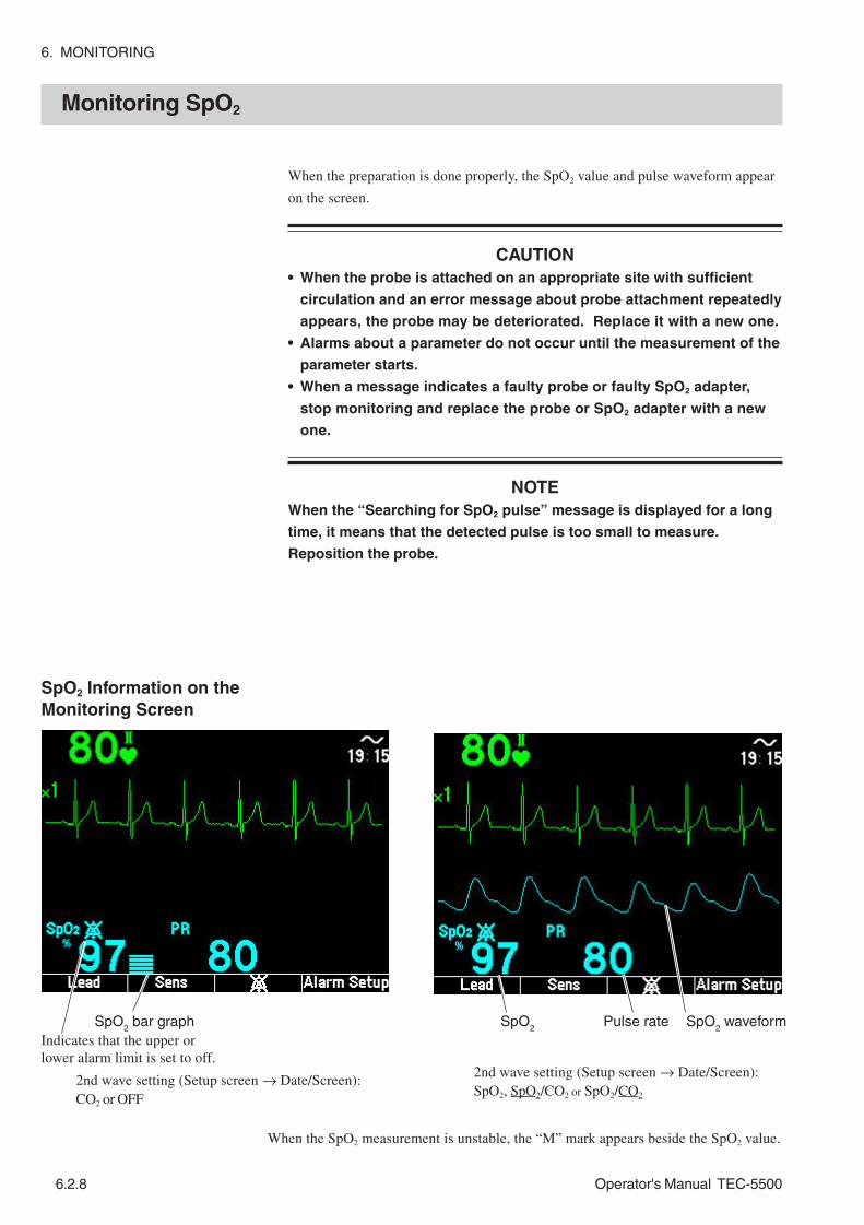
6. MONITORING
6.2.8 Operator's Manual TEC-5500
Monitoring SpO2
When the preparation is done properly, the SpO2 value and pulse waveform appear
on the screen.
CAUTION• When the probe is attached on an appropriate site with sufficient
circulation and an error message about probe attachment repeatedly
appears, the probe may be deteriorated. Replace it with a new one.
• Alarms about a parameter do not occur until the measurement of the
parameter starts.
• When a message indicates a faulty probe or faulty SpO2 adapter,
stop monitoring and replace the probe or SpO2 adapter with a new
one.
NOTEWhen the “Searching for SpO2 pulse” message is displayed for a long
time, it means that the detected pulse is too small to measure.
Reposition the probe.
SpO2 Information on theMonitoring Screen
SpO2 bar graph SpO
2Pulse rate SpO
2 waveform
2nd wave setting (Setup screen → Date/Screen):CO2 or OFF
2nd wave setting (Setup screen → Date/Screen):SpO2, SpO2/CO2 or SpO2/CO2
Indicates that the upper orlower alarm limit is set to off.
When the SpO2 measurement is unstable, the “M” mark appears beside the SpO2 value.

6. MONITORING
Operator's Manual TEC-5500 6.2.9
Changing SpO2 Settings
Changing Settings on theSpO2 Setup Screen
The following settings can be changed for SpO2 monitoring.
2. Select “SpO2 Setup” with the Item ↓ or Item↑ key and press the SET key. The
SpO2 Setup screen appears.
1. Turn the Energy/Mode Select control to the SETUP position. The Setup Menu
screen appears.
Item Description (default settings is underlined)
Sens Set the pulse wave sensitivity AUTO, ×1/8, ×1/4, ×1/2, ×1, ×2, ×4, ×8
SpO2 Sound When set to ON, the pitch of the sync sound changes according to SpO2 value
ON, OFF
PR Set the upper and lower limit of pulse rate alarm.
Upper: 20 to 300, OFF (140) Lower: OFF, 15 to 295 (40)
SpO2 Set the upper and lower limit of the SpO2 alarm.
Upper: 51 to 100, OFF (OFF) Lower: OFF, 50 to 99 (90)
QRS Volume Set the QRS sync sound volume. 0 to 4 (3) QRS Sound Select the source of the QRS sync sound. ECG, SpO2

6. MONITORING
6.2.10 Operator's Manual TEC-5500
Changing the PulseWaveform Sensitivity
NOTEWhen an SpO2 probe is not connected to the SpO2/CO2 connector on
the defibrillator, the SpO2 setup screen is not displayed. If not
displayed, turn the Energy/Mode Select control to the MONITOR
position, confirm the SpO2 cable connection then turn the Energy/
Mode Select control to the SETUP position.
3. Press the Item key to select the item. When you press the key, the selected item
switches.
4. Press the ↓ or ↑ key to change settings. Repeat steps 3 and 4 to set all items.
5. Turn the Energy/Mode Select control to the MONITOR position. The
monitoring screen appears.
The sensitivity determines the size of the waveform on both the screen and
recording paper.
Setting range: AUTO, ×1/8, ×1/4, ×1/2, ×1 (default setting), ×2, ×4, ×8
When you select AUTO sensitivity, the appropriate sensitivity is automatically
selected.
1. On the SpO2 Setup screen, select Sens with the Item key.
2. Select the sensitivity with the ↓ or ↑ key.
AUTO → ×1/8 → ×1/4 → ×1/2 → ×1 → ×2 → ×4 → ×8

6. MONITORING
Operator's Manual TEC-5500 6.2.11
Selecting Sync SoundPitch
When this item is set to ON, the pitch of the sync sound changes according to SpO2
value, so you can know the SpO2 change by sound. Fixed sound is produced when
only SpO2 is measured.
ON: The pitch of the sync sound changes as shown in the table below.
OFF: The pitch of the sync sound is fixed (Default setting: OFF).
When the SpO2 adapter cable is disconnected from the defibrillator, the sync sound
automatically becomes the pitch for OFF. When the SpO2 adapter cable is
connected again, the pitch returns to the previous pitch.
1. On the SpO2 Setup screen, select SpO2 Sound with the Item key.
2. Select ON or OFF with the ↓ or ↑ key.
SpO2 Tone
100% to 81% Changes in 20 steps corresponding to SpO2 value (steps of 1).
80% or less Pitch for 81%

6. MONITORING
6.2.12 Operator's Manual TEC-5500
Changing the Pulse RateAlarm Limits CAUTION
When the upper or lower alarm limit is turned off, there will be no
upper or lower pulse rate alarm for that limit.
1. On the SpO2 Setup screen, select the upper or lower value of the pulse rate
(PR) limit with the Item key.
The arrow in the PR bar graph indicates the current pulse rate.
2. Select the upper or lower limit with the ↓ or ↑ key.
NOTEIf you increase the upper limit over 300, the upper limit becomes OFF.
If you decrease the lower limit below 15, the lower limit becomes OFF.
Item Range Step Default setting
Upper 20-300, OFF 5 140 PR beat/min
Lower OFF, 15-295 5 40

6. MONITORING
Operator's Manual TEC-5500 6.2.13
Changing the SpO2 AlarmLimits CAUTION
When the upper or lower alarm limit is turned off, there will be no
upper or lower SpO2 alarm for that limit.
1. On the SpO2 Setup screen, select the upper or lower SpO2 alarm limit with the
Item key.
The arrow in the SpO2 bar graph indicates the current SpO2 value.
2. Select the upper or lower limit with the ↓ or ↑ key.
NOTEIf you increase the upper limit over 100, the upper limit becomes OFF. If
you decrease the lower limit below 50, the lower limit becomes OFF.
Refer to “ECG-Monitoring - Changing QRS Sync Sound Volume” in Section 6.1.
Refer to “ECG-Monitoring - Changing QRS Sync Sound Source” in Section 6.1.
Changing QRS SyncSound Volume
Changing QRS SyncSound Source
Item Range Step Default setting
Upper 51 to 100, OFF 1 OFF SpO2 %
Lower OFF, 50 to 99 1 90

6. MONITORING
6.2.14 Operator's Manual TEC-5500
This page is intentionally left blank.

Operator's Manual TEC-5500 6.3C.1
CO2 Monitoring
General .............................................................................................................................6.3.1
CO2 Sensor Kit .......................................................................................................6.3.3
Preparing for CO2 Monitoring ............................................................................................6.3.6
Preparation Flowchart .............................................................................................6.3.6
Connecting the CO2 Sensor Kit to the Defibrillator ..................................................6.3.6
Monitoring CO2 ...................................................................................................................................................................................................... 6.3.7
CO2 Information on the Monitoring Screen ..............................................................6.3.7
Changing CO2 Settings.....................................................................................................6.3.8
Changing Settings on the CO2 Setup Screen .........................................................6.3.8
Changing the CO2 Scale .........................................................................................6.3.9
Changing the etCO2 Alarm Limits ......................................................................... 6.3.10
Changing the Respiration Rate Alarm Limits ........................................................ 6.3.11
Changing the APNEA Alarm Limit ......................................................................... 6.3.12
Inspection of Measuring Accuracy .................................................................................. 6.3.13
Daily Inspection of Measuring Accuracy ............................................................... 6.3.13
Inspection of Measuring Accuracy (Precise Method) ............................................ 6.3.13
Checking Procedure ................................................................................... 6.3.14

6.3C.2 Operator's Manual TEC-5500
This page is intentionally left blank.

6. MONITORING
Operator's Manual TEC-5500 6.3.1
General
CO2 monitoring by the mainstream method is performed by connecting the TG-
901T3T or G-921T3 CO2 sensor kit to the patient’s respiration circuit and to the
SpO2/CO
2 connector on the defibrillator. For the proper CO
2 sensor attachment and
use, refer to the operator’s manual of the CO2 sensor
WARNING• When performing defibrillation or cardioversion during CO2
monitoring with the CO2 sensor kit, remove the sensor from the
patient. When the sensor cannot be removed, do not touch the
sensor cable because the discharged energy may cause serious
electrical burn, shock or other injury.
• With the TG-901T3 CO2 sensor kit, measurements are based on the
assumption of no CO2 gas in the inspiration. The CO2 concentration
in the respiration is calculated by taking the CO2 concentration in
the inspiration as 0 mmHg. Therefore, measuring CO2 by connecting
the CO2 sensor kit to a patient under mouth-to-mouth respiration or
to a Jackson Rees circuit or Mapleson D circuit where CO2 gas may
be present during inspiration may result in the acquired data being
lower than the actual value.
• With the TG-901T3 CO2 sensor kit, this monitor cannot monitor CO2 of
patients weighing less than 10 kg (22 lbs).
• Do not use the airway adapter on neonates because the dead space
volume of the airway adapter is about 5 mL.
• When using the YG-101T airway adapter on children or patients with
low ventilatory amount, the CO2 may mix in the inspiration due to
the airway adapter’s dead space volume (5 mL), resulting in
inaccurate measured values or difficulty in detecting no breath.
Perform ventilation taking into consideration the 5 mL dead space
volume.
• Before MRI examination, remove the CO2 sensor kit from the patient.
Failure to follow this warning may cause serious electrical burn on
the patient due to local heating caused by dielectric electromotive
force. For details, refer to the MRI operator’s manual.
CAUTION• The CO2 data may be inaccurate when monitoring a patient with an
extremely high respiration rate or irregular respiration. Read the
measured values carefully.
• Measured value may be incorrect when the operating temperature
changes greatly.
• When using an anesthetic instrument with a volatile anesthetic
agent, the CO2 measurement may be inaccurate.

6. CO2 MONITORING
6.3.2 Operator's Manual TEC-5500
NOTEThe measurement may be inaccurate when the defibrillator is used in
the following conditions. Read the measured values carefully.
• When there is high concentration nitrous oxide gas in the airway
adapter.
• When used in places with low atmospheric pressure such as at high
altitude.
• When used in environments with sudden temperature changes.
• When used in environments with severe humidity.
• When used for patients with irregular spontaneous respiration.

6. MONITORING
Operator's Manual TEC-5500 6.3.3
CO2 Sensor KitWARNING
••••• Do not use the airway adapter on neonates because the dead space
volume of the airway adapter is about 5 mL.
••••• When using the YG-101T airway adapter on children or patients with
low ventilatory amount, the CO2 may mix in the inspiration due to
the airway adapter’s dead space volume (5 mL), resulting in
inaccurate measured values or difficulty in detecting apnea.
Perform ventilation taking into consideration the 5 mL dead space
volume.
••••• When using the YG-121T nasal adapter on children or patients with
low ventilatory amount, the CO2 may mix in the inspiration due to
the nasal adapter’s dead space volume (1.2 mL), resulting in
inaccurate measured values or difficulty in detecting apnea.
Perform ventilation taking into consideration the 1.2 mL dead space
volume.
••••• When you use YG-122T together with an oxygen cannula, check that
the oxygen cannula is correctly attached on the patient by referring
to other parameters and by observing the patient periodically.
••••• If arterial oxygen saturation does not increase, immediately stop
using the oxygen cannula with the CO2 sensor kit and select another
way to supply oxygen.
••••• The only oxygen cannula that can be used with YG-122T is #1103
manufactured by HUDSON RCI. Do not use any other oxygen
cannula. Other oxygen cannulas cannot be attached and oxygen
cannot be delivered to the patient through the nostrils.
••••• Check that the oxygen cannula tube is not bent, broken, or blocked
by the nasal tube. If the ends of the oxygen cannula tube turn too far
up or down, it causes insufficient oxygen supply or the CO2 value
may be incorrect.
CAUTION••••• The airway adapter/nasal adapter is non-sterilized and disposable.
Use only for a single patient and single use. Failure to follow this
instruction causes cross infection.
••••• Do not sterilize the airway adapter. Safety cannot be guaranteed if
the airway adapter is sterilized.
••••• Use the Nihon Kohden specified airway adapter.
••••• With the TG-901T3 CO2 sensor kit, secure the CO2 sensor to the
respiration circuit so that the transparent film of the airway adapter
is perpendicular to the floor. If the transparent film is parallel to the
floor, water droplets may get onto the transparent film and affect the
measurement accuracy.

6. CO2 MONITORING
6.3.4 Operator's Manual TEC-5500
CAUTION continued••••• Failure to follow the instructions below degrades the anti-fogging
ability of the transparent film and results in incorrect measurement.
- Replace the airway adapter/nasal adapter with a new one every
24 hours.
- Replace the airway adapter/nasal adapter with a new one if
blood, sputum or mucus adhere to the transparent film.
- Do not damage the transparent film. Do not let dust or detergent
contact the transparent film. Do not touch, wipe or clean the
transparent film with fingers or cleaners.
••••• Never autoclave or perform EOG gas sterilization for the TG-901T3
CO2 sensor kit. It damages the CO2 sensor kit and safety cannot be
guaranteed.
••••• When using the YG-121T/YG-122T nasal adapter on a patient with
bleeding disorder, poor general medical condition or malnutrition,
observe the patient condition all the time. The mouth guide touches
the mouth and may cause pressure sores.
••••• When using the YG-121T nasal adapter on children or patients with
low ventilatory amount, the CO2 may mix in the inspiration due to
the nasal adapter’s dead space volume (1.2 mL), resulting in
inaccurate measured values or difficulty in detecting apnea.
Perform ventilation taking into consideration the 1.2 mL dead space
volume.
••••• When you use YG-122T together with an oxygen cannula, check that
the oxygen cannula is correctly attached on the patient by referring
to other parameters and by observing the patient periodically.
••••• With the TG-901T3 CO2 sensor kit, secure the CO2 sensor to the
respiration circuit so that the transparent film of the airway adapter
is perpendicular to the floor. If the transparent film is parallel to the
floor, water droplets may get onto the transparent film and affect the
measurement accuracy.
••••• Failure to follow the instructions below degrades the anti-fogging
ability of the transparent film and results in incorrect measurement.
- Replace the airway adapter/nasal adapter with a new one every
24 hours.
- Replace the airway adapter/nasal adapter with a new one if
blood, sputum or mucus adhere to the transparent film.
- Do not damage the transparent film. Do not let dust or detergent
contact the transparent film. Do not touch, wipe or clean the
transparent film with fingers or cleaners.
••••• Never autoclave or perform EOG gas sterilization for the TG-901T3
CO2 sensor kit. It damages the CO2 sensor kit and safety cannot be
guaranteed.
••••• When using the YG-121T/YG-122T nasal adapter on a patient with
bleeding disorder, poor general medical condition or malnutrition,
observe the patient condition all the time. The mouth guide touches
the mouth and may cause pressure sores.

Operator's Manual TEC-5500 6.3.5
6. MONITORING
TG-901T3 CO2 Sensor kit YG-101T Airway Adapter
For over 3 years old or over 10 kg
OPER/ALARM
CO2 ADAPTER
JG-901T3 CO2 adapter
TG-101T CO2 sensor
HOPER/ALARM
CO2 ADAPTER
TG-921T3 CO2 Sensor Kit
TG-121T CO2 sensor
JG-921T3 CO2 adapter
Nasal tube
Clip
Mouth guide
Holder for oxygen cannula
YG-120T(for nasal breathing)
YG-121T(for naso-oral)
YG-122T(for oxygen cannula)
Model Patient Weight Dead space volume Code No. YG-101T Adult 10 kg or more 5 cc R801
Description Model Q’ty Code No. Nasal adapter (for nasal breathing) YG-120T 30 V921 Nasal adapter (for naso-oral breathing) YG-121T 30 V922 Nasal adapter (for oxygen cannula adjustment) YG-122T 30 V923

6. CO2 MONITORING
6.3.6 Operator's Manual TEC-5500
Preparing for CO2 Monitoring
Preparation Flowchart
Connecting the CO2 SensorKit to the Defibrillator
1. Connect the CO2 sensor kit to the SpO
2/CO
2 connector on the defibrillator.
2. Connect the CO2 sensor to the respiration circuit.
3. Start measurement and change necessary settings.
For handling accessories after use, refer to Section 10.
Connect the CO2 sensor kit to the SpO
2/CO
2 connector on the defibrillator.

6. MONITORING
Operator's Manual TEC-5500 6.3.7
Monitoring CO2
CO2 Information on theMonitoring Screen
After completing the preparation, CO2 monitoring starts.
CAUTIONWhen the “CO2 sensor not working” or “CO2 adapter abnormality”
message is displayed, check the CO2 sensor kit and replace it if
necessary. CO2 cannot be monitored while the message is displayed.
NOTE• When using the TG-901T3/TG-921T3 CO2 sensor kit, it performs
calibration automatically every minute and when any of the following
occurs.
- Defibrillator power on
- Patient’s first respiration
- Airway adapter is removed from the CO2 sensor and connected
again.
- Respiration stops for 20 seconds.
- Signal changes rapidly due to temperature change.
• During calibration, the CO2 waveform becomes flat (0 mmHg) but the
respiration rate and measured value are not affected.
2nd wave setting (Setup screen → Date/Screen):SpO2 or OFF
2nd wave setting (Setup screen → Date/Screen):CO2, SpO2/CO2 or SpO2/CO2
Respiration rate
CO2 waveformCO
2 valueCO
2 bar graph
Indicates that the upper orlower alarm limit is set to off.

6. CO2 MONITORING
6.3.8 Operator's Manual TEC-5500
Changing CO2 Settings
Changing Settings on theCO2 Setup Screen
The following settings can be changed for CO2 monitoring.
1. Turn the Energy/Mode Select control to the SETUP position. The Setup Menu
screen appears.
2. Select “CO2 Setup” with the Item ↓ or Item ↑ key and press the SET key. The
CO2 Setup screen appears.
Item Description (default settings are underlined.)
Scale Set the scale of CO2 waveform 0 to 40, 0 to 80 (mmHg) 0 to 5.3, 0 to10.7 (kPa) mmHg Upper: 2 to 99, OFF (50)
Lower: OFF, 1 to 98 (20) etCO2
Set the upper and lower limit of the CO2 alarm. kPa Upper: 1.0 to 13.5, OFF (7.0)
Lower: OFF, 0.5 to 13.0 (3.0)
RR Set the upper and lower limit of the respiration rate alarm.
Upper: 2 to 150, OFF (OFF) Lower: OFF, 0 to 148 (OFF)
APNEA Set the upper limit of the APNEA alarm. Upper: 5 to 40, OFF (OFF)

6. MONITORING
Operator's Manual TEC-5500 6.3.9
Changing the CO2 Scale
3. Press the Item key to select the item. When you press the key, the selected
item switches.
4. Press the key for “↓” or “↑” to change settings. Repeat steps 3 and 4 to set all
items.
5. Turn the Energy/Mode select control to the MONITOR position to return to the
monitoring screen appears.
Select the appropriate scale for the patient CO2 waveform.
Setting range: 0 to 40, 0-80 (default setting)
(0 to 5.3, 0-10.7 when kPa is selected)
1. On the CO2 Setup screen, select Scale with the Item key.
2. Select the scale with the ↓ or ↑ key.

6. CO2 MONITORING
6.3.10 Operator's Manual TEC-5500
Changing the etCO2 AlarmLimits
Set the upper and lower limit for the etCO2 alarm.
CAUTIONWhen the upper or lower alarm limit is turned off, there will be no
etCO2 upper or lower alarm for that limit.
1. On the CO2 Setup screen, select etCO
2 upper or lower limit with the Item key.
· The arrow in the etCO2 bar graph indicates the current etCO2 value.
2. Select the upper or lower limit with the ↓ or ↑ key.
NOTEIf you increase the upper limit over 99 (mmHg) or 13.5 (kPa), the upper
limit becomes OFF. If you decrease the lower limit below 1 (mmHg) or
0.5 (kPa), the lower limit becomes OFF.
Item Range Step Default setting
Upper 2-99, OFF 1 50 mmHg
Lower OFF, 1 to 98 1 20
Upper 1.0 to 13.5, OFF 0.5 7.0 etCO2
kPa Lower OFF, 0.5 to 13.0 0.5 3.0

6. MONITORING
Operator's Manual TEC-5500 6.3.11
Changing the RespirationRate Alarm Limits
NOTEIf you increase the upper limit over 150, the upper limit becomes OFF.
If you decrease the lower limit below 0, the lower limit becomes OFF.
The arrow in the RR bar graph indicates the current respiration rate.
2. Select the upper or lower limit with the ↓ or ↑ key.
Set the upper and lower limit for the respiration rate alarm.
CAUTIONWhen the upper or lower alarm limit is turned off, there will be no
respiration rate upper or lower alarm for that limit.
1. On the CO2 Setup screen, select respiration rate upper or lower limit with the
Item key.
Item Range Step Default setting
Upper 2 to 150, OFF 2 OFF RR count/min
Lower OFF, 0 to 148 2 OFF

6. CO2 MONITORING
6.3.12 Operator's Manual TEC-5500
Changing the APNEAAlarm Limit
Set the period of no respiration for the APNEA alarm. When the defibrillator
cannot detect patient respiration for more than the selected seconds, the APNEA
alarm occurs.
CAUTIONWhen the alarm limit is turned off, there will be no APNEA alarm for
that limit.
1. On the CO2 Setup screen, select APNEA with the Item key.
2. Select apnea alarm limit with the ↓ or ↑ key.
NOTEIf you increase the upper limit over 40, the upper limit becomes OFF.
Item Range Step Default setting
APNEA s Upper 5 to 40, OFF 5 OFF

6. MONITORING
Operator's Manual TEC-5500 6.3.13
Inspection of MeasuringAccuracy (Precise Method)
Inspection of Measuring Accuracy
Perform daily accuracy inspection using your own respiration.
Put the larger end of the airway adapter (side for connecting to the patient’s mask
and tracheal tube) into your mouth and after stabilizing breathing, breathe in the
same way as in the resting state at a rate of 5 seconds per breath (12 breaths/
minute). Breathing too quickly or taking deep breaths will disable standard
measurements.
The standard etCO2 concentration is 40 mmHg. Check that the CO
2 gas
concentration display is from 35 to 45 mmHg.
Check the measurement accuracy whenever you suspect the defibrillator is not
reading correctly. This procedure does not calibrate CO2 sensor. It only checks the
measurement accuracy. If the measurement accuracy is not appropriate, contact
your Nihon Kohden distributor.
The following parts are required.
CAUTION• Only use the specified items.
• Follow the CAUTION label on the CO2 gas cylinder.
• After the lifetime of the CO2 gas cylinder expires, the measurement
accuracy cannot be guaranteed.
• 5% CO2 calibration gas
Manufacturer: Nellcor Puritan Bennett or Scott Medical Products
Cylinder name: OD (1 L disposable cylinder)
Outlet connection: CGA 600
Gas volume: 25 L (Provides about 50 to 100 calibrations)
Gas component: 5% CO2, 21% O
2, balance N
2
Accuracy: ±0.03% absolute
Expiration: 3 years after the gas is packed in the cylinder
• Flow regulator PR-150 flow regulator (Full scale 700 psi)
Manufacturer: VICTOR High Purity & Instrumentation
Delivery flow (flow rate): 0.5 L/min
Inlet connection: CGA 600
• Tube
Internal diameter: 4 mm
Daily Inspection ofMeasuring Accuracy

6. CO2 MONITORING
6.3.14 Operator's Manual TEC-5500
• Slip joint
Manufacturer: Portex
Specification: 100/252 4 mm
When using a CO2 gas cylinder and flow regulator other than the above, the
following specifications must be met. Make sure that the outlet connection of the
gas cylinder and the inlet connection of the flow regulator fit together.
• 5% CO2 calibration gas
Gas component: 5% CO2, 21% O
2, balance N
2
Accuracy: ±0.03% absolute
• Flow regulator
Delivery flow (flow rate): 0.5 L/min
Checking Procedure
1. Connect the flow regulator to the CO2 gas cylinder by rotating the flow
regulator clockwise. Connect them firmly.
2. Connect the CO2 sensor kit to the SpO
2/CO
2 connector on the defibrillator.
3. Connect the airway adapter to the CO2 sensor so that the marks on the
airway adapter and CO2 sensor align.
4. After checking that the CO2 gas cylinder is connected properly, gently turn the
knob of the flow regulator counterclockwise about half a turn to start the gas
flow.
5. Connect the slip joint to the airway adapter. CO2 gas flows in the airway
adapter and the instCO2 on the screen should read 38 mmHg. (Expiration
phase, 38 mmHg CO2 gas)
6. Disconnect the slip joint from the airway adapter and shake the CO2 sensor to
remove CO2 gas from the airway adapter. Open air flows into the airway
adapter and instCO2 on the screen should be 0 mmHg. (Inspiration phase, no
CO2 gas)
Slip jointKnob
Pressure gauge
Connect/disconnect the airway adapter repeatedly.
Pressure gauge Knob

6. MONITORING
Operator's Manual TEC-5500 6.3.15
CAUTION• This method assumes that no CO2 gas is present in the inspiration
phase of breathing. Therefore, step 6 has to be performed to
simulate the inspiration phase of breathing so that the defibrillator
can correctly determine the CO2 concentration. The defibrillator
determines the CO2 concentration by comparing the change in CO2
concentration in the airway adapter during the inspiration and
expiration phase of breathing.
• The defibrillator calculates the CO2 concentration by assuming that
the gas temperature is 37°°°°°C and the surrounding pressure is 1
atmospheric pressure. Therefore, if this checking procedure is
performed at room temperature or lower, the defibrillator will display
higher instCO2 (there will be −−−−−0.4% per °°°°°C difference).
Correspondingly, if the checking procedure is performed at high
altitude, the defibrillator will display a lower instCO2 reading (there
will be 1 mmHg/30 hPa difference).
7. Repeat steps 5 and 6 a few times and compare the readings of step 5. The
readings should be the same.
8. After checking, gently turn the flow regulator knob clockwise to stop the gas
flow.
NOTEWhen the pressure gauge of the flow regulator reads 0, replace the CO2
gas cylinder with a new one.

6. CO2 MONITORING
6.3.16 Operator's Manual TEC-5500
This page is intentionally left blank.

Operator's Manual TEC-5500 7C.1
Section 7 Alarm Function
General .............................................................................................................................. 7.1
Alarm Types ............................................................................................................. 7.1
Alarm Indication ....................................................................................................... 7.1
Alarm List ................................................................................................................. 7.2
Alarm Status Marks and Messages ......................................................................... 7.4
Temporarily Silencing an Alarm After It Occurs ................................................................. 7.5
Silencing Alarms ...................................................................................................... 7.5
Resuming Alarms .................................................................................................... 7.5
Suspending an Alarm Before It Occurs .............................................................................. 7.6
Suspending Alarms ................................................................................................. 7.6
Automatic Alarm Recording ............................................................................................... 7.6
Setting Alarms ................................................................................................................... 7.7
Alarm Setting Range................................................................................................ 7.7
Setting Alarm Settings on the Alarm Setup Screen ................................................. 7.8
Setting Alarm Settings on the Alarm Setup Screen of the Setup Screen ................ 7.9
Setting Alarms Individually ..................................................................................... 7.10

7C.2 Operator's Manual TEC-5500
This page is intentionally left blank.

7. ALARM FUNCTION
Operator's Manual TEC-5500 7.1
General
Alarm Indication
Alarm Types
Alarms let you know abnormalities of measurement environment, instrument and
measurement value of each parameter by messages on the screen and sound.
Alarms are categorized into three types.
When an alarm occurs,
• An alarm sounds.
• An alarm message appears on the screen. For a vital alarm, the measurement
value is highlighted.
• Automatic alarm recording starts. (only for vital alarms and only when the alarm
recording is set to ON.)
You can turn the alarm recording ON/OFF on the System Setup - Configuration
screen. Refer to Section 3.
Alarm Description
Instrument alarm Generated when any instrument abnormality is detected. (for example, discharged battery or out of recording paper)
Alarm for measurement environment
Generated when any abnormality is detected in measurement environment. (for example, connector off, check electrode, check probe, etc)
Vital alarm Generated when each measurement value exceeds previously set upper/lower limits.

7. ALARM FUNCTION
7.2 Operator's Manual TEC-5500
Alarm List
1 3
0
Type Alarm Alarm Display Alarm Sound
Battery discharged (battery remaining charge is 1/3 )
Charge battery ( )
Displayed during detection
Continuous or beeping tone*
INTERNAL DISCHARGE
Out of paper
No report data
Low impedance
High impedance
Displayed for 5 seconds For 5 seconds
Instrument Alarm (2)
Time to replace battery Displayed during detection No alarm sound
Type Alarm Alarm Display Alarm Sound
SpO2 probe not working
SpO2 module not working
CO2 adapter abnormality
CO2 sensor not working
CO2 module not working
Overheating
High voltage monitor error
Relay drive error
Insert battery
Power abnormality
Charge battery (blinking )
Replace battery
FET error
ERROR K×××
ERROR P×××
ERROR D×××
ERROR C×××
ERROR A×××
Continuous tone Instrument Alarm (1)
Set energy to 50J or less
Displayed during detection
Continuous or beeping tone*
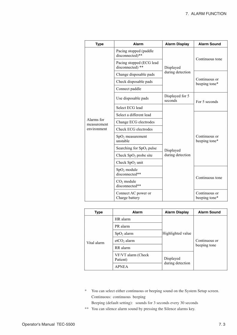
Operator's Manual TEC-5500 7. 3
7. ALARM FUNCTION
* You can select either continuous or beeping sound on the System Setup screen.
Continuous: continuous beeping
Beeping (default setting): sounds for 3 seconds every 30 seconds
** You can silence alarm sound by pressing the Silence alarms key.
Type Alarm Alarm Display Alarm Sound
Pacing stopped (paddle disconnected)**
Pacing stopped (ECG lead disconnected) **
Continuous tone
Change disposable pads
Check disposable pads
Connect paddle
Displayed during detection
Continuous or beeping tone*
Use disposable pads Displayed for 5 seconds
Select ECG lead For 5 seconds
Select a different lead
Change ECG electrodes
Check ECG electrodes
SpO2 measurement unstable
Searching for SpO2 pulse
Check SpO2 probe site
Check SpO2 unit
Continuous or beeping tone*
SpO2 module disconnected**
CO2 module disconnected**
Continuous tone
Alarms for measurement environment
Connect AC power or Charge battery
Displayed during detection
Continuous or beeping tone*
Type Alarm Alarm Display Alarm Sound
HR alarm
PR alarm
SpO2 alarm
etCO2 alarm
RR alarm
Highlighted value
VF/VT alarm (Check Patient)
Vital alarm
APNEA
Displayed during detection
Continuous or beeping tone

7. ALARM FUNCTION
7.4 Operator's Manual TEC-5500
Alarm off mark:
• Displayed at every parameter for which the upper and/or lower alarm limit is set
to OFF.
• Displayed at a parameter whose alarm is silenced.
• Displayed at every parameter when all alarms are suspended.
Value:
Highlighted while the value exceeds the alarm limit.
“Alarm off” message:
• Displayed at the top of the screen when any vital alarm upper/lower limit is set to
OFF.
• When the “Alarm silenced 2 min”, “Alarm silenced 1 min”, “Alarms suspended 2
min” or “Alarms suspended 1 min” message is displayed, the “Alarm off”
message is not displayed. When the alarm silence or suspension finishes, it is
displayed again.
• Disappears when all alarm settings are set to settings other than OFF.
VF/VT alarm off mark:
• Displayed at the upper right corner of the screen.
• Displayed when VF/VT analysis is not performed.
• Displayed when “VF/VT Alarm” is set to “OFF” in Alarm Setup screen.
• Displayed when the paddle lead is selected and the external paddles or internal
paddles is connected.
• Displayed when the Setup screen, pacing screen, Basic checks screen or Alarm
Setup screen is selected.
Alarm Status Marks andMessages

7. ALARM FUNCTION
Operator's Manual TEC-5500 7.5
Temporarily Silencing an Alarm After It Occurs
Silencing Alarms
* Instrument Alarm (1) on the page 7.2
Resuming Alarms
When an alarm occurs, you can silence the alarm sound for two minutes.
NOTEAlarms which indicate instrument abnormalities* are not silenced by
pressing the Silence alarms key.
• When the following alarms occur, contact your Nihon Kohden
distributor or representative.
SpO2 probe not working Power abnormality
SpO2 module not working FET error
CO2 adapter abnormality ERROR K×××××××××××××××
CO2 sensor not working ERROR P×××××××××××××××
CO2 module not working ERROR D×××××××××××××××
Overheating ERROR C×××××××××××××××
High voltage monitor error ERROR A×××××××××××××××
Relay drive error
• When the following alarms occur, take a remedial action immediately,
referring to section 9.
Insert battery
Charge battery (blinking 0 mark)
Replace battery
During alarm silence,
• the alarm sound is silenced
• the “Alarm silenced 2 min” “Alarm silenced 1 min” message is displayed at the
top of the screen.
When the alarm cause is removed during alarm silence, the alarm is cleared.
Press the Silence alarms key on the front panel.
Alarms resume when:
• The cause of alarm continues after the alarm silence ends.
• The Silence alarms key is pressed during alarm silence.
• A different alarm (except for instrument alarm (2)) occurs.
• The cause of alarm disappears during alarm silence, then the same alarm occurs
again.

7. ALARM FUNCTION
7.6 Operator's Manual TEC-5500
Suspending an Alarm Before It Occurs
Automatic Alarm Recording
Suspending Alarms
When automatic alarm recording is set to ON, waveforms beginning 4 seconds
before and ending 8 seconds after the alarm are automatically recorded when an
alarm is generated. For details, refer to Section 8.
An alarm can also be suspended before it occurs, for example, before you replace
the electrodes. The alarm suspend time is two minutes.
During alarm suspension, all alarms are suspended and
• the alarm sound is silenced.
• The “Alarms suspended 2 min” or “Alarms suspended 1 min” message is
displayed.
Press the Silence alarms key on the front panel when no alarms are occurring.
WARNINGDuring alarm suspension (“Alarm off” or “Alarms suspended” message
displayed), all current alarms except for instrument alarm group 1 are
turned off.
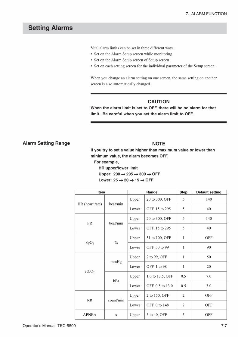
7. ALARM FUNCTION
Operator's Manual TEC-5500 7.7
Vital alarm limits can be set in three different ways:
• Set on the Alarm Setup screen while monitoring
• Set on the Alarm Setup screen of Setup screen
• Set on each setting screen for the individual parameter of the Setup screen.
When you change an alarm setting on one screen, the same setting on another
screen is also automatically changed.
CAUTIONWhen the alarm limit is set to OFF, there will be no alarm for that
limit. Be careful when you set the alarm limit to OFF.
NOTEIf you try to set a value higher than maximum value or lower than
minimum value, the alarm becomes OFF.
For example,
HR upper/lower limit
Upper: 290 →→→→→ 295 →→→→→ 300 →→→→→ OFF
Lower: 25 →→→→→ 20 →→→→→ 15 →→→→→ OFF
Setting Alarms
Alarm Setting Range
Item Range Step Default setting
Upper 20 to 300, OFF 5 140 HR (heart rate) beat/min
Lower OFF, 15 to 295 5 40
Upper 20 to 300, OFF 5 140 PR beat/min
Lower OFF, 15 to 295 5 40
Upper 51 to 100, OFF 1 OFF SpO2 %
Lower OFF, 50 to 99 1 90
Upper 2 to 99, OFF 1 50 mmHg
Lower OFF, 1 to 98 1 20
Upper 1.0 to 13.5, OFF 0.5 7.0 etCO2
kPa Lower OFF, 0.5 to 13.0 0.5 3.0
Upper 2 to 150, OFF 2 OFF RR count/min
Lower OFF, 0 to 148 2 OFF
APNEA s Upper 5 to 40, OFF 5 OFF
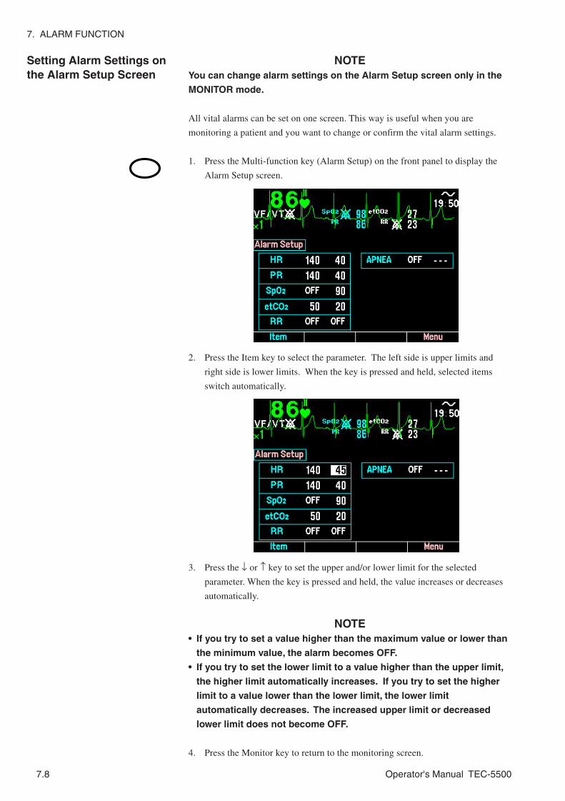
7. ALARM FUNCTION
7.8 Operator's Manual TEC-5500
Setting Alarm Settings onthe Alarm Setup Screen
NOTEYou can change alarm settings on the Alarm Setup screen only in the
MONITOR mode.
All vital alarms can be set on one screen. This way is useful when you are
monitoring a patient and you want to change or confirm the vital alarm settings.
1. Press the Multi-function key (Alarm Setup) on the front panel to display the
Alarm Setup screen.
2. Press the Item key to select the parameter. The left side is upper limits and
right side is lower limits. When the key is pressed and held, selected items
switch automatically.
3. Press the ↓ or ↑ key to set the upper and/or lower limit for the selected
parameter. When the key is pressed and held, the value increases or decreases
automatically.
NOTE• If you try to set a value higher than the maximum value or lower than
the minimum value, the alarm becomes OFF.
• If you try to set the lower limit to a value higher than the upper limit,
the higher limit automatically increases. If you try to set the higher
limit to a value lower than the lower limit, the lower limit
automatically decreases. The increased upper limit or decreased
lower limit does not become OFF.
4. Press the Monitor key to return to the monitoring screen.

7. ALARM FUNCTION
Operator's Manual TEC-5500 7.9
Setting Alarm Settings onthe Alarm Setup Screen ofthe Setup Screen
All vital alarms can be set on one screen.
1. Turn the Energy/Mode Select control to the SETUP position. The Setup Menu
screen appears.
2. Select “Alarm Setup” with the Item ↓ or Item ↑ key and press the SET key.
The Alarm Setup screen appears.
3. Press the Item key to select the parameter. When the key is pressed and held,
selected items switch automatically.
4. Press the ↓ or ↑ key to set the upper and/or lower limit for the selected
parameter. When the key is pressed and held, the value increases or decreases
automatically.
NOTE• If you try to set a value higher than the maximum value or lower than
the minimum value, the alarm becomes OFF.
• If you try to set the lower limit to a value higher than the upper limit,
the higher limit automatically increases. If you try to set the higher
limit to a value lower than the lower limit, the lower limit
automatically decreases. The increased upper limit or decreased
lower limit does not become OFF.
5. Turn the Energy/Mode Select control to the MONITOR position.

7. ALARM FUNCTION
7.10 Operator's Manual TEC-5500
You can set each vital alarm on each parameter setup screen.
Example: Setting the ECG alarm
1. Turn the Energy/Mode Select control to the SETUP position. The Setup Menu
screen appears.
Setting Alarms Individually
2. Select “ECG Setup” with the Item ↓ or Item ↑ key and press SET key. The
ECG Setup screen appears.
3. Select “HR” with the Item key. When the key is pressed and held, selected
items switch automatically.
4. Select the heart rate upper and/or lower limit with the ↓ or ↑ key. When the key
is pressed and held, the value increases or decreases automatically.
NOTE• If you try to set a value higher than the maximum value or lower than
the minimum value, the alarm becomes OFF.
• If you try to set the lower limit to a value higher than the upper limit,
the higher limit automatically increases. If you try to set the higher
limit to a value lower than the lower limit, the lower limit
automatically decreases. The increased upper limit or decreased
lower limit does not become OFF.
5. Turn the Energy/Mode Select control to the MONITOR position.

Operator's Manual TEC-7700 8C.1
Section 8 Recording
About Recording ................................................................................................................ 8.1
Changing Report and Recorder Settings ........................................................................... 8.3
Manual Recording .............................................................................................................. 8.4
Real Time or Delayed Waveform Recording ............................................................ 8.4
Procedure ...................................................................................................... 8.4
Report Recording .................................................................................................... 8.5
Periodic List Report Recording ...................................................................... 8.5
Alarm Report Recording ................................................................................ 8.5
Event List Report Recording .......................................................................... 8.6
Defibrillation Report Recording ...................................................................... 8.8
VF Analysis Report Recording ...................................................................... 8.9
Trend Report Recording .............................................................................. 8.10
Event Recording ...................................................................................................... 8.11
Saving the Administered Medication ....................................................................... 8.12
Automatic Recording ......................................................................................................... 8.13
Record On Charging After Discharge....................................................................... 8.13
Alarm Recording ...................................................................................................... 8.14
Periodic Recording .................................................................................................. 8.15
Printed Letters and Marks ................................................................................................. 8.16

8C.2 Operator's Manual TEC-7700
This page is intentionally left blank.

8. RECORDING
Operator's Manual TEC-5500 8.1
About Recording
Available recording types are shown on the next page.
NOTEWhen the screen changes to any setup screen during recording,
recording automatically stops. Record again after you exit the setup
screen.
For the recording examples in this section, “Printing character size” is set to
“Small” in the System Setup - Configuration screen.

8. RECORDING
8.2 Operator's Manual TEC-5500
* The Alarm, Defib and VF Analysis reports share memory. The length/capacity of recorded data is shown for one report
type when no data for the other two report types is saved in memory. If data of more than one report types is saved in
memory, the maximum length/capacity of recorded data for each report type decreases.
** This data is used for Alarm report recording.
*** This data is used for Defib report recording.
Recording mode Recorded data Length/Capacity of
recorded data Start/Stop Operation
(Real time or delayed) Waveform recording
Waveform on the screen Either real time or 4 seconds delayed waveform recording can be selected. (Delayed is the default setting.)
Continuous Press the Record key. To stop during recording, press the Record key.
Periodic List Periodic measurement data Up to 120 measurement data The periodic measurement interval can be selected on the Recorder Setup screen.
Alarm ECG waveforms and another parameter waveform when an alarm occurs or the Event key is pressed.
Waveforms for up to 60 alarms* (when ECG is selected at “RecWave” on the Recorder Setup screen.)
Event list Event list Up to 130 events Defib Waveform at discharge and
settings Up to 44 discharges* Waveform from 10 seconds before to 12 seconds after discharge
VF Analysis Waveforms of 6 seconds after the CHARGE/AED button is pressed and the analysis result
Up to 124 analyses*
Report recording
Trend Trend graph and numeric data 1, 2, 4, 8 or 24 hours. You can set the recorded period at “Trend Time” on the Report Setup screen.
Press the Record key when the Report Setup screen is displayed. To stop during recording, press the Record key.
Manual recording
Event recording** ECG waveform when the Event key is pressed.
Waveform from 4 seconds before to 8 seconds after the Event key is pressed.
Press the Event key. To stop during recording, press the Record key.
Record on charging after discharge***
ECG waveform before and after discharge
ECG from the start of energy charging to 6 or 12 seconds after discharge
Starts when the defibrillator starts charging energy. To stop during recording, press the Record key.
Alarm recording** ECG waveform when an alarm occurs
ECG waveform from 4 seconds before to 8 seconds after alarm occurrence.
Starts automatically. To stop recording, press the Record key.
Automatic recording
Periodic recording Periodic ECG, SpO2 and CO2 delayed waveforms
For 12 seconds The recording interval is set at “PeriodicRec” on the Recorder Setup screen.
Starts automatically. To stop recording, press the Record key.
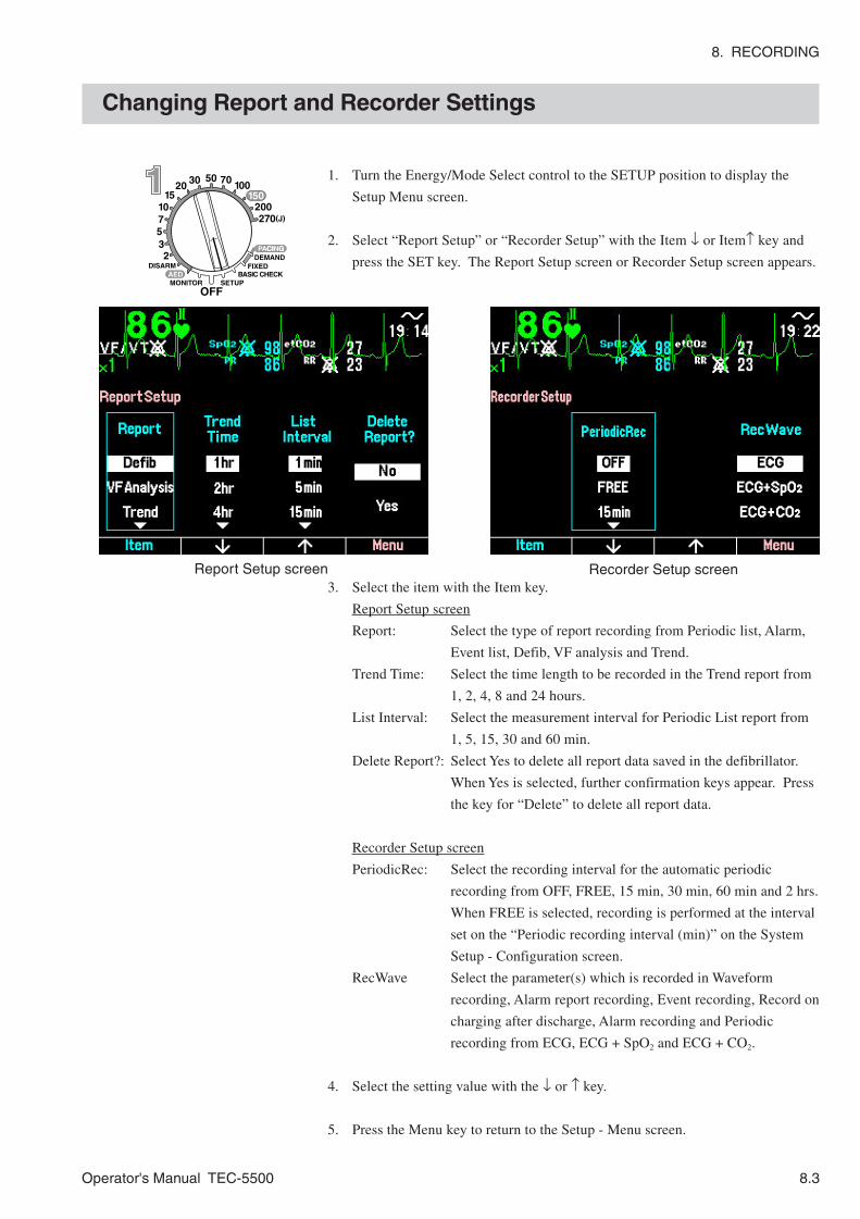
8. RECORDING
Operator's Manual TEC-5500 8.3
1. Turn the Energy/Mode Select control to the SETUP position to display the
Setup Menu screen.
2. Select “Report Setup” or “Recorder Setup” with the Item ↓ or Item↑ key and
press the SET key. The Report Setup screen or Recorder Setup screen appears.
3. Select the item with the Item key.
Report Setup screen
Report: Select the type of report recording from Periodic list, Alarm,
Event list, Defib, VF analysis and Trend.
Trend Time: Select the time length to be recorded in the Trend report from
1, 2, 4, 8 and 24 hours.
List Interval: Select the measurement interval for Periodic List report from
1, 5, 15, 30 and 60 min.
Delete Report?: Select Yes to delete all report data saved in the defibrillator.
When Yes is selected, further confirmation keys appear. Press
the key for “Delete” to delete all report data.
Recorder Setup screen
PeriodicRec: Select the recording interval for the automatic periodic
recording from OFF, FREE, 15 min, 30 min, 60 min and 2 hrs.
When FREE is selected, recording is performed at the interval
set on the “Periodic recording interval (min)” on the System
Setup - Configuration screen.
RecWave Select the parameter(s) which is recorded in Waveform
recording, Alarm report recording, Event recording, Record on
charging after discharge, Alarm recording and Periodic
recording from ECG, ECG + SpO2 and ECG + CO2.
4. Select the setting value with the ↓ or ↑ key.
5. Press the Menu key to return to the Setup - Menu screen.
Changing Report and Recorder Settings
Report Setup screen Recorder Setup screen
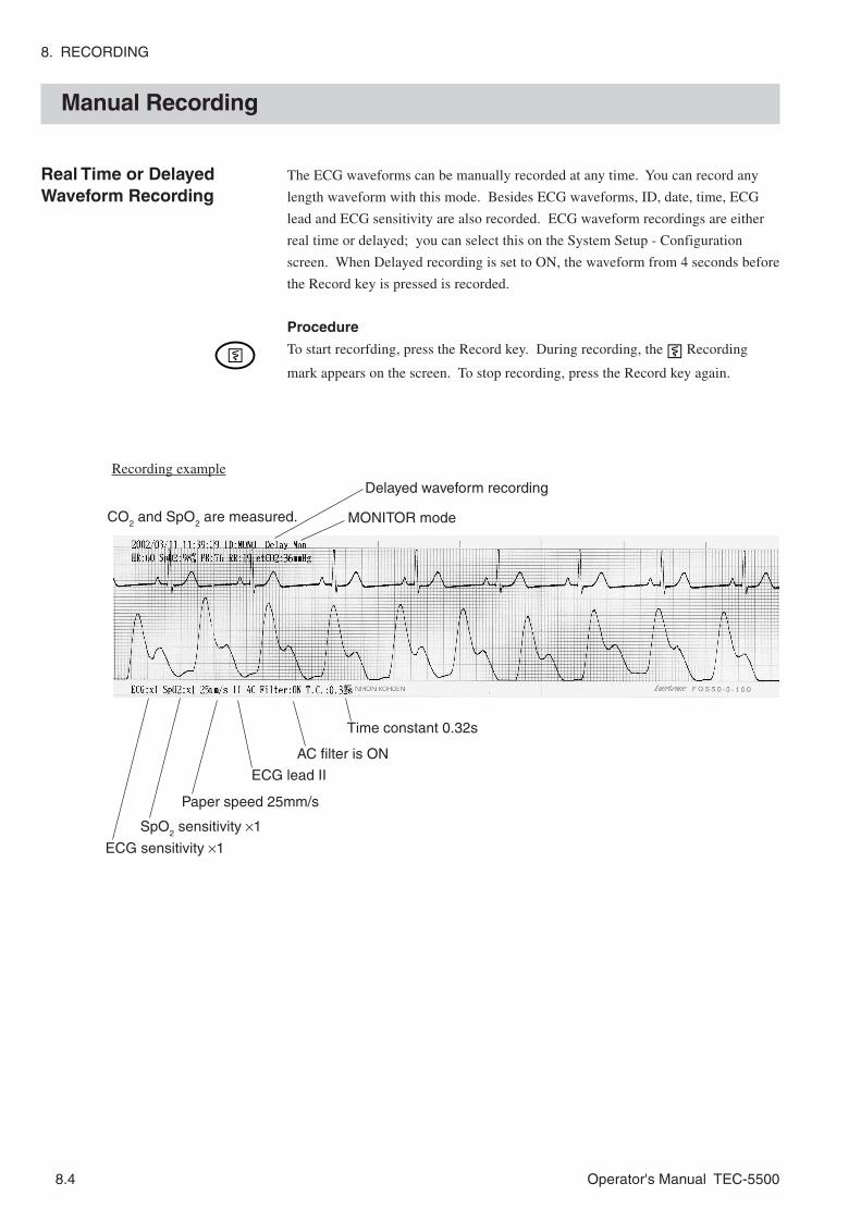
8. RECORDING
8.4 Operator's Manual TEC-5500
Manual Recording
Real Time or DelayedWaveform Recording
CO2 and SpO
2 are measured.
Delayed waveform recording
MONITOR mode
ECG sensitivity ×1
SpO2 sensitivity ×1
Paper speed 25mm/s
AC filter is ON
ECG lead II
Time constant 0.32s
Recording example
The ECG waveforms can be manually recorded at any time. You can record any
length waveform with this mode. Besides ECG waveforms, ID, date, time, ECG
lead and ECG sensitivity are also recorded. ECG waveform recordings are either
real time or delayed; you can select this on the System Setup - Configuration
screen. When Delayed recording is set to ON, the waveform from 4 seconds before
the Record key is pressed is recorded.
Procedure
To start recorfding, press the Record key. During recording, the Recording
mark appears on the screen. To stop recording, press the Record key again.

8. RECORDING
Operator's Manual TEC-5500 8.5
Report Recording There are six kinds of report recording: Periodic list, Alarm, Event list, Defib, VF
analysis and Trend. To do report recording, you need to display the Report Setup
screen. Set the following settings on the Report Setup screen.
Periodic List Report Recording
Measurement values for each parameter at the selected interval are recorded in a
list format.
Procedure
1. Select “Periodic list” at the Report on the Report Setup screen. Refer to
“Changing Report and Recorder Settings” in this section.
2. Press the Record key. The Report recording mark appears on the screen.
The recording stops when all data are recorded.
To stop recording, press the Record key again.
You can select the measurement interval at List Interval on the Report Setup screen.
The data for the Periodic list report recording remains in memory after the power
off.
Alarm Report Recording
ECG waveform and either SpO2 or CO2 waveform when the Event key is pressed or
when an alarm occurs is recorded. The recorded data are the same as that of the
Event recording and automatic alarm recording.
Procedure
1. Select “Alarm” at the Report on the Report Setup screen. Refer to “Changing
Report and Recorder Settings” in this section.
2. Press the Record key. The Report recording mark appears on the screen.
The recording stops when all data are recorded.
To stop during recording, press the Record key again.
The data for the Alarm report recording remains in memory after the power off.
• Waveforms for up to 60 alarms are saved when ECG is selected at RecWave on
the Recorder Setup screen. After waveforms for 60 alarms are saved, when
another alarm occurs, the waveform for that alarm is saved and the oldest 15
waveforms are deleted.
• Waveforms for up to 48 alarms are saved when ECG and SpO2 are selected at
RecWave on the Recorder Setup screen. After waveforms for 48 alarms are
saved, when another alarm occurs, the waveform for that alarm is saved and the
oldest 12 waveforms are deleted.
• Waveforms for up to 56 alarms are saved when ECG and CO2 are selected at
RecWave on the Recorder Setup screen. After waveforms for 56 alarms are
saved, when another alarm occurs, the waveform for that alarm is saved and the
oldest 14 waveforms are deleted.

8. RECORDING
8.6 Operator's Manual TEC-5500
Event List Report Recording
The list of defibrillator usage history with clock time are recorded in a
chronological order. This is useful for an operation diary or defibrillator operation
history.
Procedure
1. Select “Event list” at the Report on the Report Setup screen. Refer to
“Changing Report and Recorder Settings” in this section.
2. Press the Record key. The Report recording mark appears on the screen.
The recording stops when all data are recorded.
To stop during recording, press the Record key again.
The data for the Event list report recording remains in memory after the power is
turned off.
Up to 10 events are recorded on one column. Up to 130 events are recorded. After
130 event data are saved, when the defibrillator detects another event, the oldest
data is deleted.
Recording examples
(1) When the Event key is pressed
(2) When an alarm occurs
Recording example
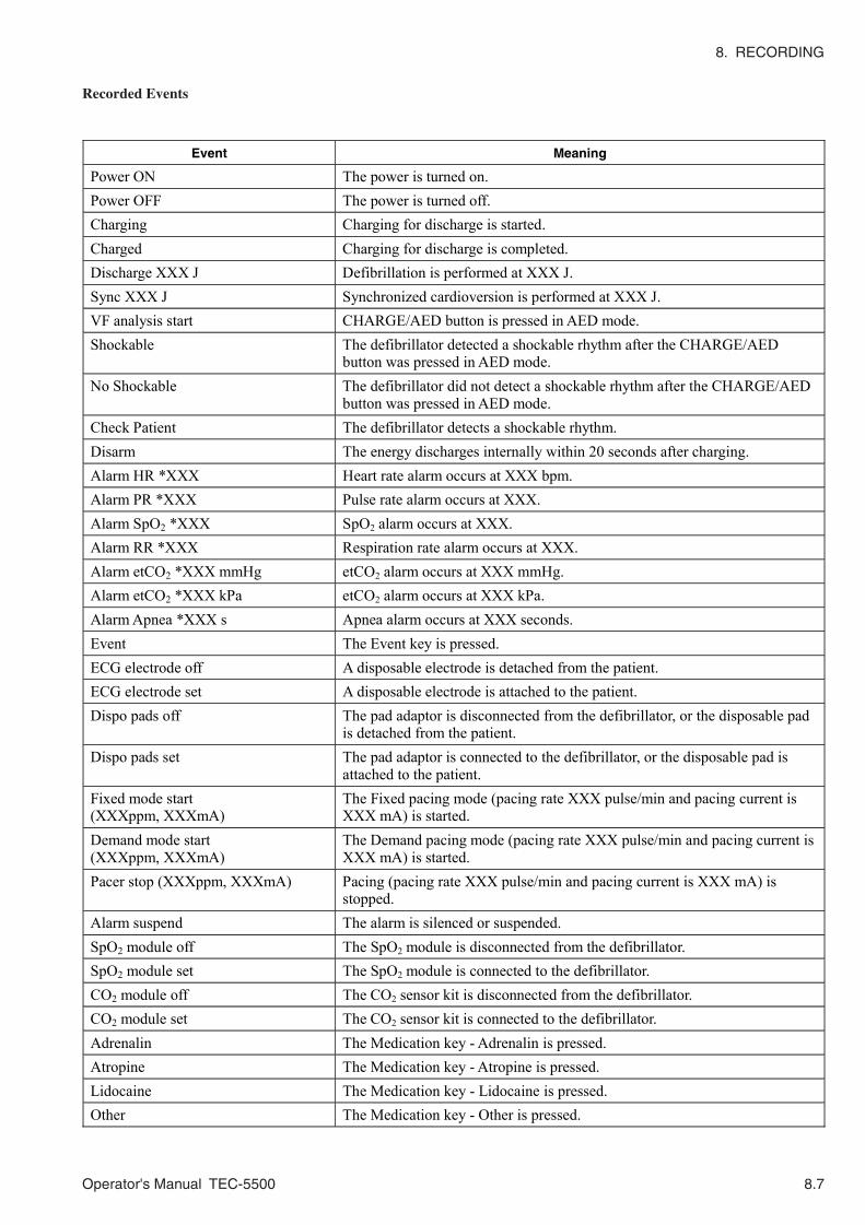
8. RECORDING
Operator's Manual TEC-5500 8.7
Recorded Events
Event Meaning
Power ON The power is turned on. Power OFF The power is turned off. Charging Charging for discharge is started. Charged Charging for discharge is completed. Discharge XXX J Defibrillation is performed at XXX J. Sync XXX J Synchronized cardioversion is performed at XXX J. VF analysis start CHARGE/AED button is pressed in AED mode. Shockable The defibrillator detected a shockable rhythm after the CHARGE/AED
button was pressed in AED mode. No Shockable The defibrillator did not detect a shockable rhythm after the CHARGE/AED
button was pressed in AED mode. Check Patient The defibrillator detects a shockable rhythm. Disarm The energy discharges internally within 20 seconds after charging. Alarm HR *XXX Heart rate alarm occurs at XXX bpm. Alarm PR *XXX Pulse rate alarm occurs at XXX. Alarm SpO2 *XXX SpO2 alarm occurs at XXX. Alarm RR *XXX Respiration rate alarm occurs at XXX. Alarm etCO2 *XXX mmHg etCO2 alarm occurs at XXX mmHg. Alarm etCO2 *XXX kPa etCO2 alarm occurs at XXX kPa. Alarm Apnea *XXX s Apnea alarm occurs at XXX seconds. Event The Event key is pressed. ECG electrode off A disposable electrode is detached from the patient. ECG electrode set A disposable electrode is attached to the patient. Dispo pads off The pad adaptor is disconnected from the defibrillator, or the disposable pad
is detached from the patient. Dispo pads set The pad adaptor is connected to the defibrillator, or the disposable pad is
attached to the patient. Fixed mode start (XXXppm, XXXmA)
The Fixed pacing mode (pacing rate XXX pulse/min and pacing current is XXX mA) is started.
Demand mode start (XXXppm, XXXmA)
The Demand pacing mode (pacing rate XXX pulse/min and pacing current is XXX mA) is started.
Pacer stop (XXXppm, XXXmA) Pacing (pacing rate XXX pulse/min and pacing current is XXX mA) is stopped.
Alarm suspend The alarm is silenced or suspended. SpO2 module off The SpO2 module is disconnected from the defibrillator. SpO2 module set The SpO2 module is connected to the defibrillator. CO2 module off The CO2 sensor kit is disconnected from the defibrillator. CO2 module set The CO2 sensor kit is connected to the defibrillator. Adrenalin The Medication key - Adrenalin is pressed. Atropine The Medication key - Atropine is pressed. Lidocaine The Medication key - Lidocaine is pressed. Other The Medication key - Other is pressed.

8. RECORDING
8.8 Operator's Manual TEC-5500
Recording example
Defibrillation Report Recording
Waveform at defibrillation and cardioversion and discharge information are recorded.
Procedure
1. Select “Defib” in ”Report” on the Report Setup screen. Refer to “Changing Report
and Recorder Settings” in this section.
2. Press the Record key. The Report recording mark appears on the screen. The
recording stops when all data are recorded.
To stop during recording, press the Record key again,
The data for the Defibrillation report recording remains in memory after the power off.
Compressed ECG waveform is recorded in three rows. The amplitude of the recorded
waveform is 1/2 of the waveform on the screen (on screen: 10 mm/1mV → 5 mm/1mV)
Waveform of 22 seconds (10 seconds before and 12 seconds after discharge) and setting at
the discharge are recorded for one discharge. Up to 44 discharges are recorded. After 44
data are saved, when the defibrillator detects another discharge, the data for that discharge
is saved and the oldest 11 data (both waveform and setting at discharge) are deleted.
When another discharge is performed within 22 seconds after previous discharge, the
recording is extended for 12 seconds after the second discharge and is counted as one
recording. In this case, maximum recordable discharge is less than 44.
Up to 6 discharge marks “ ” are recorded on one waveform.
Discharge information
Date: Date when defibrillation or cardioversion is performed.
Time: Clock time when defibrillation or cardioversion is performed.
Set Energy: Selected energy value
TTR: Skin-paddle (pad) contact impedance
Delivered: Output energy value. When TTR is 15 Ω or less, or 255 Ω or more, 0 J is
printed.
Shock Times: Total counts after the defibrillator power is turned on.
Manual: Defibrillation (“Manual Sync” is for Synchronized cardioversion and
“AED” is for AED)
TEST: Printed only when energy discharge test is performed.
OK: Test OK NG: Test NG

8. RECORDING
Operator's Manual TEC-5500 8.9
Recording examples
VF Analysis Report Recording
Waveforms of 6 seconds after the CHARGE/AED button is pressed and the analysis
result are recorded.
Procedure
1. Select “VF Analysis” in “Report” on the Report Setup screen. Refer to
“Changing Report and Recorder Settings” in this section.
2. Press the Record key. The Report recording mark appears on the screen.
The recording stops when all data are recorded.
To stop during recording, press the Record key again.
The data of the VF Analysis report recording remains in memory when the
defibrillator power is turned off.
Waveforms for up to 124 VF analyses are saved. After 124 waveforms are saved,
when the defibrillator performs another VF analysis, the waveform for that VF
analysis is saved and the oldest 31 data are deleted.

8. RECORDING
8.10 Operator's Manual TEC-5500
Recording examples
(1) Heart rate and SpO2
Trend Report Recording
The trend graph and numeric data of heart rate, SpO2 , PR, etCO2 and RR which are
saved in memory are recorded.
Procedure
1. Select “Trend” in “Report” on the Report Setup screen. Refer to “Changing
Report and Recorder Settings” in this section.
2. Press the Record key. The Report recording mark appears on the screen.
The recording stops when all data are recorded.
To stop during recording, press the Record key again.
The data of the Trend report recording remains in memory when the defibrillator
power is turned off.
You can select recorded trend time from 1, 2, 4, 8, 24 hours at Trend period on the
Report Setup screen. The relation between recorded trend time and interval of data
acquisition is shown below.
The maximum, minimum and average value in each data acquisition interval is
recorded.
The vertical axis scale changes according to the recorded data so that all data can
be recorded on the paper.
(1) Pulse rate and etCO2
Trend time (hours) 1 2 4 8 24 Data acquisition interval (minutes) 1 2 4 8 24

8. RECORDING
Operator's Manual TEC-5500 8.11
Event Recording
Recording example
ECG waveform from 4 seconds before to 8 seconds after the Event key is pressed
is recorded.
• When an alarm occurs, the Recording mark appears on the screen and
automatic alarm recording starts. The waveform from 4 seconds before to 12
seconds after the alarm occurrence is recorded.
• When energy charging starts, the Recording mark appears on the screen and
record on charging after discharge starts instead of event recording.
• If there is no paper in the recorder when the Event key is pressed, ECG
waveform at the time is saved as the data for alarm report recording.
(3) Respiration rate

8. RECORDING
8.12 Operator's Manual TEC-5500
Saving the AdministeredMedication
When “Medication” on the System Setup - Configuration screen is set to ON
(Default setting: OFF), the administered medication (adrenalin, atropine, lidocaine
and other) can be saved and recorded as the event list report and alarm report with
the 12 seconds of ECG waveforms.
1. Set “Medication” on the System Setup - Configuration screen to ON.
Refer to “System Setup Screen” in Section 3.
2. Press the Event key. The Event recording starts. The function keys change to
Adrenalin, Atropine, Lidocaine and Other function keys.
3. Press the key for the administered medication. The function keys return to the
normal function keys 5 seconds after the Event key is pressed.
4.. Set “Medication” on the System Setup - Configuration screen to OFF.
• Medications are not saved as sound data.
• During alam recording, if two or more medication keys are pressed, only the
latest medication is saved as the event report and alarm report.
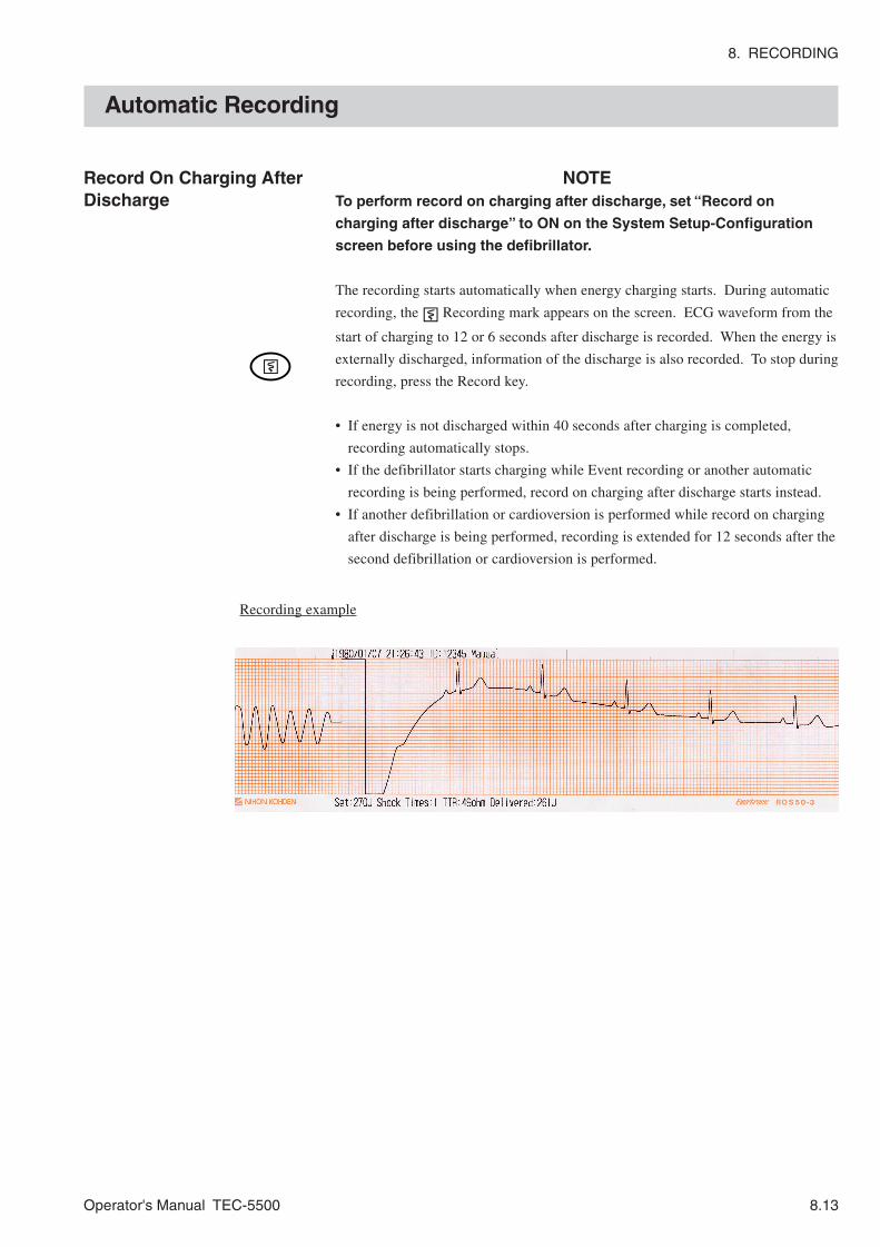
8. RECORDING
Operator's Manual TEC-5500 8.13
Automatic Recording
Record On Charging AfterDischarge
NOTETo perform record on charging after discharge, set “Record on
charging after discharge” to ON on the System Setup-Configuration
screen before using the defibrillator.
The recording starts automatically when energy charging starts. During automatic
recording, the Recording mark appears on the screen. ECG waveform from the
start of charging to 12 or 6 seconds after discharge is recorded. When the energy is
externally discharged, information of the discharge is also recorded. To stop during
recording, press the Record key.
• If energy is not discharged within 40 seconds after charging is completed,
recording automatically stops.
• If the defibrillator starts charging while Event recording or another automatic
recording is being performed, record on charging after discharge starts instead.
• If another defibrillation or cardioversion is performed while record on charging
after discharge is being performed, recording is extended for 12 seconds after the
second defibrillation or cardioversion is performed.
Recording example
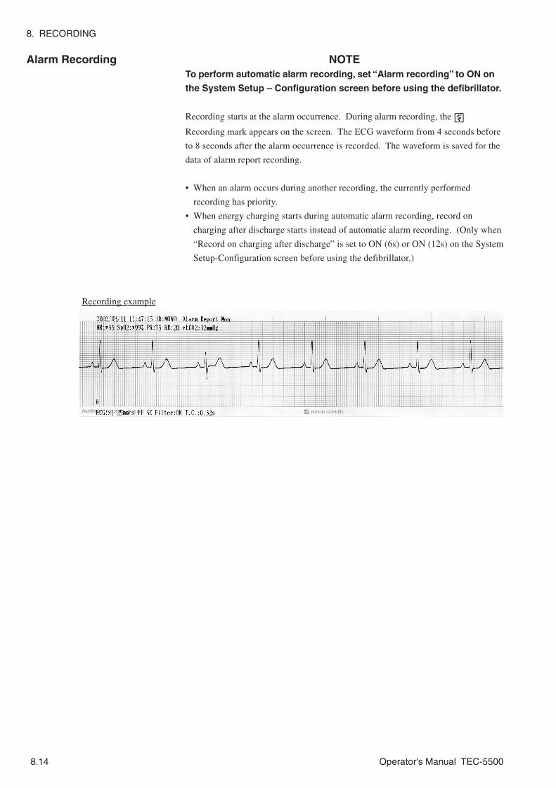
8. RECORDING
8.14 Operator's Manual TEC-5500
Alarm Recording NOTETo perform automatic alarm recording, set “Alarm recording” to ON on
the System Setup – Configuration screen before using the defibrillator.
Recording starts at the alarm occurrence. During alarm recording, the
Recording mark appears on the screen. The ECG waveform from 4 seconds before
to 8 seconds after the alarm occurrence is recorded. The waveform is saved for the
data of alarm report recording.
• When an alarm occurs during another recording, the currently performed
recording has priority.
• When energy charging starts during automatic alarm recording, record on
charging after discharge starts instead of automatic alarm recording. (Only when
“Record on charging after discharge” is set to ON (6s) or ON (12s) on the System
Setup-Configuration screen before using the defibrillator.)
Recording example

8. RECORDING
Operator's Manual TEC-5500 8.15
Periodic Recording Recording automatically starts at a preset interval. 12 seconds of the waveform(s)
selected at RecWave on the Recorder Setup screen is recorded. Besides ECG
waveforms, ID, date, time, ECG lead and ECG sensitivity are also recorded. Only
delayed ECG waveform is recorded.
For recording interval, Select either 15 min, 30 min, 60 min, 2hr or FREE at
PeriodicRec on the Recorder Setup screen.
When OFF is selected, automatic periodic recording is not performed.
When FREE is selected, recording is performed at the interval set on the “Periodic
recording interval (min)” on the System Setup - Configuration screen.
Recording example

8. RECORDING
8.16 Operator's Manual TEC-5500
Printed Letters and Marks
Item Printed letters Description
Event Report Event report recording
Defib Report Defibrillation report recording
Trend Report Trend report recording
List Report List report recording
Alarm Report Alarm report recording
Recording type
VF Report VF analysis report recording
Real Real time waveform recording Real time/Delayed recording*1
Delay Delayed waveform recording
Mon Monitoring mode
Manual Defib Manual defibrillation mode
AED AED mode
Fix Pace Fixed Pacing mode
Operation mode
Demand Pace Demand Pacing Mode
YYYY/MM/DD Year/Month/Day
MMM/DD/YYYY Month/Day/Year
YYYY/MMM/DD Year/Month/Day
Date*1
DD/MM/YYYY Day/Month/Year
Clock time *2 XX:XX:XX Hour:Minute:Second
Instrument ID *1 ID: XXXXX
ECG sensitivity ×1/4, ×1/2, ×1, ×2, ×4, AUTO×1/4, AUTO×1/2, AUTO×1, AUTO×2, AUTO×4
Paper speed *1 50 mm/s
25 mm/s
ECG lead PADDLE, I, II, III, aVR, aVL, aVF, V, AUX, TEST
SpO2 sensitivity *2 SpO2: ×8, ×4, ×2, ×1, ×1/2, ×1/4, ×1/8, AUTO
CO2 scale *1, *2 0-40 mmHg, 0-80 mmHg, 0-5.3kPa, 0-10.7kPa
AC Filter: ON AC filter ON AC filter *2
AC Filter: OFF AC filter OFF
T.C.: 0.32s 0.32 second Time constant *2
T.C.: 3.2 s 3.2 second
Heart rate *3 HR: XX
SpO2 *3 SpO2: XX%
Pulse rate *3 PR: XX
Respiration rate *3 RR: XX
etCO2 *3 etCO2: XX mmHg, XX kPa
The point of discharge
Selected energy Set: XXX J
Shock times Shock Times: XX
TTR TTR: XXX ohm
Delivered energy Delivered: XXX J
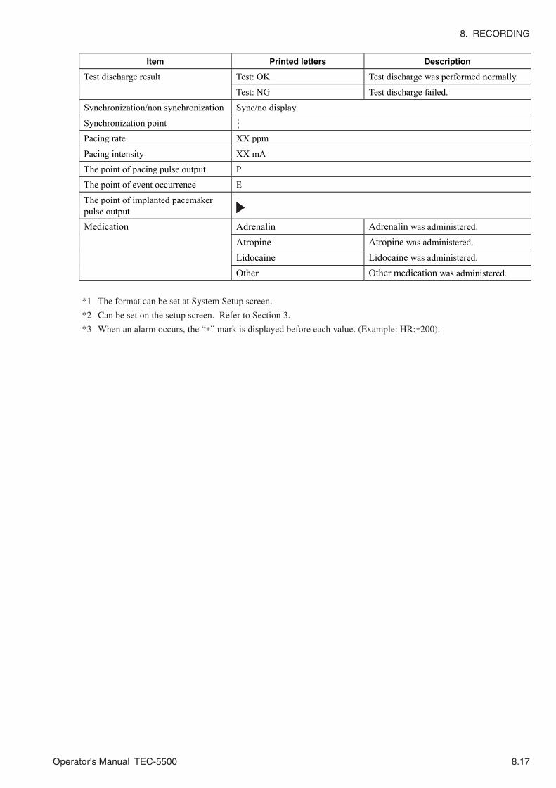
8. RECORDING
Operator's Manual TEC-5500 8.17
*1 The format can be set at System Setup screen.
*2 Can be set on the setup screen. Refer to Section 3.
*3 When an alarm occurs, the “*” mark is displayed before each value. (Example: HR:*200).
Item Printed letters Description
Test: OK Test discharge was performed normally. Test discharge result
Test: NG Test discharge failed.
Synchronization/non synchronization Sync/no display
Synchronization point
Pacing rate XX ppm
Pacing intensity XX mA
The point of pacing pulse output P
The point of event occurrence E
The point of implanted pacemaker pulse output
Medication Adrenalin Adrenalin was administered.
Atropine Atropine was administered.
Lidocaine Lidocaine was administered.
Other Other medication was administered.

8. RECORDING
8.18 Operator's Manual TEC-5500
This page is intentionally left blank.

Operator's Manual TEC-5500 9C.1
Section 9 Messages andTroubleshooting
Messages ............................................................................................................................9.2
Troubleshooting ................................................................................................................. 9.10
General .................................................................................................................... 9.10
Defibrillation ............................................................................................................. 9.11
Pacing (TEC-5531 Series Only) ............................................................................... 9.11
Monitoring ............................................................................................................... 9.12
ECG .............................................................................................................. 9.12
SpO2 ............................................................................................................................................................................................... 9.13
CO2 ................................................................................................................................................................................................... 9.14
Recording ................................................................................................................ 9.15
Battery .................................................................................................................... 9.16
SD Card .................................................................................................................. 9.16

9C.2 Operator's Manual TEC-5500
This page is intentionally left blank.

9. MESSAGES AND TROUBLESHOOTING
Operator's Manual TEC-5500 9.1
When trouble occurs, take quick action referring to the table below. If there is any
damage or the defibrillator or its peripheral component is suspected to be faulty,
turn the power off, attach a “Unusable” or “Repair request” label and contact your
Nihon Kohden distributor or representative.

9. MESSAGES AND TROUBLESHOOTING
9.2 Operator's Manual TEC-5500
Messages
Message Description Action
AED AED mode is selected. ---
Alarm off One or more alarms for parameters available for measurement is set to OFF. ---
Alarm silenced 1 min Alarm is silenced for 1 minute. ---
Alarm silenced 2 min Alarm is silenced for 2 minutes. ---
Alarms suspended All alarms are suspended. This message is displayed only during basic checks. ---
Alarms suspended 1 min Remaining time of alarm suspension is 1 minute. ---
Alarms suspended 2 min When no alarm is occurring and the SILENCE ALARMS key is pressed, this message is displayed. Remaining time of alarm suspension is 2 minutes.
---
Analyzing VF The defibrillator is performing VF/VT analysis. ---
APNEA Respiration was not detected for the period set on the Alarm screen. ---
Basic checks complete Basic checks are complete. --- Basic checks OK Basic checks are normally complete. ---
Battery discharged Very little battery charge remains. ---
Battery charge timed out During battery test The battery was not fully charged 5 hours after battery charging started.
---
Battery charging error During battery test An error occurred in battery charging
---
Battery discharge timed out
During battery test The voltage did not decrease to the specified level 3 hours after battery discharging started.
---
Battery test complete Appears when battery test finishes. (when charging for the next use is complete) ---
Battery OK Battery test result is 70 to 100% ---
Battery WEAK Battery test result is 50 to 69%. ---

9. MESSAGES AND TROUBLESHOOTING
Operator's Manual TEC-5500 9.3
Message Description Action
A card other than specified ones is inserted. Cannot use card
A card for version upgrade is inserted on the Save Report screen.
---
Capacitor test fail Capacitor test failed. ---
Capacitor test pass Capacitor test result is OK. ---
Change disposable pads Deteriorated disposable pads (Abnormal polarization voltage in PADDLE lead) ---
Change ECG electrodes Deteriorated ECG electrodes (Abnormal polarization voltage in ECG leads) ---
Change to monitor mode The multi-function key was pressed in a mode other than the MONITOR mode ---
CHARGED In manual or AED mode, high voltage energy charging is complete. ---
Charge battery There is little battery charge remaining. The mark is displayed. ---
CHARGING In manual or AED mode, the instrument is adjusting the energy in the capacitor. The defibrillator is charging high voltage energy.
---
Charging battery During battery test The battery is being charged for the battery test.
---
An ECG electrode is detached from the patient. --- Check ECG electrodes
ECG connection cable or external ECG cable is disconnected from the ECG connector. ---
In manual or AED mode, the contact impedance of the disposable pads is over 350 Ω.
When PADDLE lead is selected, disposable pads are not attached to the patient firmly.
• Clip hair on the skin where pads are placed, then firmly attach the disposable pads to the patient chest.
• Firmly connect the pad adaptor and disposable pads.
The pad adaptor is disconnected from the disposable pads.
Firmly connect the pad adaptor and disposable pads.
Check disposable pads
In FIXED or DEMAND pacing mode, the disposable pad is not firmly attached to the patient.
Firmly attach the disposable pads to the patient chest.
Check patient In background analysis, patient ECG was judged as a shockable rhythm. ---
0

9. MESSAGES AND TROUBLESHOOTING
9.4 Operator's Manual TEC-5500
Message Description Action
Check pulse This message appears: • After third defibrillation is performed in
AED mode • When the defibrillator did not detect a
shockable rhythm.
---
The probe attachment site is not appropriate. Attach the probe at a site indicated in the probe operator’s manual.
Check SpO2 probe site
The probe lifetime is expired. Replace the probe with a new one.
The probe is detached from the patient. Check the probe attachment condition and remove the cause.
The probe is disconnected from the SpO2 adapter.
Securely connect the probe to the SpO2 adapter.
Check SpO2 probe
The probe expired. Replace the probe with a new one.
Checking battery During battery test Battery capacity is being checked.
---
Connect AC Power or Charge Battery
In AED mode, the battery is discharged and the energy for the defibrillation cannot be charged.
Replace the battery or use AC power.
Connect external paddles to paddle holders
Appears when performing basic checks and the external paddles are not set on the paddle holders.
---
Connect to AC power The defibrillator is not connected to AC power during battery test.
Connect the defibrillator to AC power.
In FIXED or DEMAND pacing mode, the pad adaptor is not connected to the defibrillator.
Connect the pad adaptor to the defibrillator and then turn the Energy/Mode Select control to FIXED or DEMAND position
In manual or AED mode, paddles or disposable pads are not connected to the defibrillator.
Connect the paddles or disposable pads to the defibrillator.
Connect paddle
When PADDLE lead is selected, paddles or disposable pads are not connected to the defibrillator.
Connect the paddles or disposable pads to the defibrillator.
Insufficient light Refer to the operator’s manual of the CO2 sensor kit.
CO2 adapter abnormality
CO2 adapter is faulty or deteriorated. Replace the CO2 adapter with a new one.
CO2 sensor not working CO2 sensor is faulty or deteriorated. Replace the CO2 sensor with a new one.
CO2 module not working CO2 module is faulty. Contact your Nihon Kohden distributor or representative.
CO2 module disconnected
CO2 cable is disconnected from the defibrillator.
You can make this message disappear by pressing the Silence alarms key. Connect the CO2 cable to the SpO2/CO2 connector. If the message still appears, contact your Nihon Kohden distributor or representative.

9. MESSAGES AND TROUBLESHOOTING
Operator's Manual TEC-5500 9.5
Message Description Action
Defibrillation necessary. Check ECG
By VF analysis with the CHARGE/AED button, defibrillation was judged to be necessary.
---
Defibrillation not necessary. Check ECG.
By VF analysis with the CHARGE/AED button, defibrillation was judged to be unnecessary.
---
Demand Demand pacing mode is selected. ---
Discharging battery During battery test The battery is being discharged for battery test.
---
Did the alarm sound? The basic checks-Alarm check is being performed. ---
Did the recorder print? The basic checks-Recorder check is being performed. ---
Enter password Password to enter manual mode is required. Enter a password.
Enter password again Entered password is not correct. Enter the correct password.
ERROR A××× Faulty HV
ERROR C××× Communication error
ERROR D××× Faulty ROM/RAM
ERROR K××× Faulty keys
ERROR P××× Faulty pacing unit
Turn the Energy/Mode Select control to the OFF position. Then turn on the defibrillator and do the same operation that you did when the error message appeared. If the error message still appears, immediately turn off the power and contact your Nihon Kohden distributor or representative.
FET error The circuit to measure remaining battery charge is faulty.
Contact your Nihon Kohden distributor or representative.
File Error Sound data saved in the SD card is damaged. ---
Fixed FIXED pacing mode is selected. ---
High impedance Skin-paddle contact impedance is too high. Press the paddles on the patient firmly.
High voltage monitor error Faulty high voltage unit Turn the Energy/Mode Select control to the OFF position. Then turn on the defibrillator and do the same operation that you did when the error message appeared. If the error message still appears, immediately turn off the power and contact your Nihon Kohden distributor or representative.

9. MESSAGES AND TROUBLESHOOTING
9.6 Operator's Manual TEC-5500
Message Description Action
Appears 5 seconds after the confirmation message after CPR is displayed. ---
If no pulse, press CHARGE/AED button
When not performing CPR, appears 5 seconds after the message confirming pulse. ---
If no pulse, start CPR When CPR time is set in AED mode, this message appears after third defibrillation. ---
INTERNAL DISCHARGE Energy was not discharged to the patient. ---
Insert ATA CARD You tried to save data in a memory card when no card was inserted in the defibrillator.
Insert a specified memory card into the defibrillator.
Insert battery You tried to do the battery test when the battery was not inserted in the defibrillator. ---
Left side CO2 not measured A CO2 cable was connected to the left SpO2/CO2 connector when a CO2 cable was already connected to the right SpO2/CO2 connector.
Only one CO2 can be measured. If two CO2 cables are connected, only the first connected CO2 is measured. Disconnect one of the CO2 cables.
Left side SpO2 not measured A SpO2 cable was connected to the left SpO2/CO2 connector when a SpO2 cable was already connected to the right SpO2/CO2 connector.
Only one SpO2 can be measured. If two SpO2 cables are connected, only the first connected SpO2 is measured. Disconnect one of the SpO2 cables.
Low impedance Skin-paddle contact impedance is too low. Check that the paddles do not touch each other.
Manual defibrillation? “Manual defib confirmation” is set to “confirm” and the Energy/Mode select control is turned to the position of defibrillation.
---
No report data You tried to do report recording when there was no data for report recording saved in the defibrillator
---
Not enough free memory Very little free memory in the SD card. ---
Now pacing Pacing is started. ---
Now playing Sound is playing back ---
Out of recording paper Change the role of recording paper. Out of paper
Recorder door is open. Press the magazine until it clicks.
Faulty high voltage unit Overheating
The defibrillator discharged too frequently and the internal temperature is too high.
Turn the Energy/Mode Select control to the OFF position and leave the defibrillator for 20 minutes. Then turn on the defibrillator and check if the message appears again. If it still appears, immediately turn off the power and contact your Nihon Kohden distributor or representative.

9. MESSAGES AND TROUBLESHOOTING
Operator's Manual TEC-5500 9.7
Message Description Action
Pacing stopped (ECG lead disconnected)
Pacing stopped because: (1) An electrode lead is disconnected from an
electrode. (2) An electrode is detached from the patient. (3) Electrode lead is disconnected from the
JC-762V connection cable. (4) Bad contact between the electrode and
lead clip. (5) Electrode lead discontinuity (6) Abnormally high polarization voltage
(1) Firmly connect the electrode lead to the
ECG electrode. (2) Replace the electrodes with new ones. (3) Firmly connect the electrode lead to the
connection cable. (4) Replace the electrode lead with a new one.
(5) Replace the electrode lead with a new one. (6) Replace the electrodes with new ones.
Pacing stopped (paddle disconnected)
Pacing stopped because: (1) The pad adaptor is disconnected from the
disposable pads.
(2) The disposable pads are detached from the patient.
(1) Firmly connect the pads to the pad
adaptor. Firmly connect the pad adaptor to the paddle connector.
(2) Attach the disposable pads to the patient.
Power abnormality Input power voltage is too high. ---
Press CHARGE/AED button
When the “Check Pulse Pattern” on the System Setup screen is set to 3 (no checking pulse), in AED mode, this message appears 5 seconds after the “Check patient” message appears.
---
Press CHARGE button Appears as the guidance for capacitor test. ---
Press DISCHARGE buttons until discharge
Appears in discharge check. ---
Relay drive error Faulty high voltage unit Contact your Nihon Kohden distributor or representative.
Replace battery Battery test result is 0 to 49%. The defibrillator judged that the battery should be replaced with a new one.
---
A CO2 cable was connected to the right SpO2/CO2 connector when a CO2 cable was already connected to the left SpO2/CO2 connector.
Right side CO2 not measured
Defibrillator power is turned on when two CO2 cables are connected.
Only one CO2 can be measured. If two CO2 cables are connected, only the first connected CO2 is measured. Disconnect one of the CO2 cables.
A SpO2 cable was connected to the right SpO2/CO2 connector when a SpO2 cable was already connected to the left SpO2/CO2 connector.
Right side SpO2 not measured
Defibrillator power is turned on when two SpO2 cables are connected.
Only one SpO2 can be measured. If two SpO2 cables are connected, only the first connected SpO2 is measured. Disconnect one of the SpO2 cables.
SD: Insert a Card SD card is not inserted. Insert the SD card into the SD card slot.
SD: Card Error Could not access the SD card. ---
SD: Ready The SD card is ready to use. ---
SD: Accessing Accessing the SD card. ---

9. MESSAGES AND TROUBLESHOOTING
9.8 Operator's Manual TEC-5500
Message Description Action
The instrument is searching for correct pulse waveform.
SpO2 value cannot be measured because of unstable pulse waveform.
Wait until the pulse waveform is detected. Searching for SpO2 pulse
The probe is detached from the patient. Check the probe attachment and remove the cause.
Select a different lead During pacing in DEMAND mode, ECG lead is set to a lead other than ECG leads. ---
Under the setting that does not permit synchronized cardioversion with PADDLE lead, SYNC mode is selected with PADDLE lead.
---
SYNC button is pressed when TEST lead is selected. ---
Select ECG lead
TEST lead is selected in pacing mode. ---
Select AED or monitor if not manual defibrillation?
When “Manual defib confirmation” is set to “password” or “confirmation” and the Energy/Mode select control is turned to the position of defibrillation.
---
Set energy to 50J or less Above 50 J is selected when the internal paddles are connected to the defibrillator. ---
Set recording paper Recording paper is not set in the recorder during basic checks.
Set the paper in the recorder.
Set to 200J You tried to perform the HV capacitor test with the energy set to other than 200J.
Set the energy to 200J.
Shutdown NOW The defibrillator is shutting down now. NOTE
While the “Shutdown NOW” message is displayed on the screen, do not disconnect the power cord from the defibrillator or AC outlet and do not remove the battery pack from the defibrillator. The internal data may be damaged.
---
SpO2 module disconnected SpO2 cable is disconnected from the defibrillator.
Connect the SpO2 to the SpO2/CO2 connector. If the message still appears, contact your Nihon Kohden distributor or representative.
The “M” mark is displayed beside the SpO2 value.
SpO2 measurement is unstable due to patient body movement
If this message appears frequently, check the patient and probe attachment condition. Reattach the probe to the patient if necessary.

9. MESSAGES AND TROUBLESHOOTING
Operator's Manual TEC-5500 9.9
Message Description Action
SpO2 module not working
Faulty SpO2 module Contact your Nihon Kohden distributor or representative.
The probe lifetime is expired. Replace the probe with a new one.
Probe discontinuity or short-circuit Replace the probe with a new one.
Faulty cable of the SpO2 adapter Replace the SpO2 adapter with a new one.
SpO2 probe not working
Faulty SpO2 probe Replace the SpO2 probe with a new one. If the message still appears, replace the SpO2 adapter.
Stand clear In AED mode, the CHARGE/AED button is pressed and the defibrillator starts VF analysis. ---
Stand clear and press DISCHARGE buttons
In AED mode, charging defibrillation energy is complete. ---
Start CPR
This message appears: • When CPR is required • After discharge for one sequence • When nonshockable rhythm is detected
---
SYNC Synchronized cardioversion is selected. ---
Test fail Energy was not discharged properly in discharge test. ---
Test OK Energy was discharged properly in energy discharge test. ---
Testing. Please wait. The defibrillator is performing the HV capacitor test. ---
Time to replace battery More than one year has passed since the key for “Reset” was pressed. ---
In FIXED or DEMAND pacing mode, disposable pads are not used. --- Use disposable pads
In AED mode, disposable pads are not used. ---
Use another instrument ERROR A××× appeared in basic checks. ---
Was the voice heard? The basic checks-voice check is being performed.
Confirm that the voice is heard.

9. MESSAGES AND TROUBLESHOOTING
9.10 Operator's Manual TEC-5500
Troubleshooting
General
Problem Possible Cause Action
The instrument is used for many hours. There is no abnormality in the instrument.
The instrument heats up.
Instrument abnormality Turn the Energy/Mode select control to OFF position and disconnect the power cord. Contact your Nihon Kohden distributor or representative.
The power cord is disconnected. Firmly connect the power cord to the AC outlet and the defibrillator.
The battery is not installed. Install the specified battery. Faulty battery Replace the battery with a new one
(NKB-301V). Remaining battery charge is low. Charge the battery.
No operation when the instrument is turned on.
Instrument abnormality Contact your Nihon Kohden distributor or representative
Screen is dim. Waveform and characters are not seen.
Instrument abnormality Contact your Nihon Kohden distributor or representative
The printed date is JAN/01/80. The backup battery is almost discharged.
Replace the backup battery with a new one. For replacement, contact your Nihon Kohden distributor or representative. (Under normal use condition, the backup battery lifetime is about 6 years.)
Faulty internal memory Contact your Nihon Kohden distributor or representative.
The report data are not saved.
On the Setup screen, the report data were deleted.
Deleted data cannot be recovered.
All settings set in the Setup screen and System Setup screen return to the default settings.
Faulty internal memory Contact your Nihon Kohden distributor or representative.
When the battery is installed, the instrument suddenly changes to battery operation.
When the battery is not installed, the instrument power suddenly drops.
Power voltage changed. Confirm the AC power cord connection. When the power cord is properly connected and the symptom still appears, contact your Nihon Kohden distributor or representative.
--- Set the date and time on the Date/Screen screen. Refer to Section 3.
The date and time printed on the recording paper is incorrect.
The backup battery for the clock is discharged.
Contact your Nihon Kohden distributor or representative.
On the screen, there are some pixels which have randomly abnormal color or do not light.
For the TFT LCD screen, it is considered normal if some pixels have randomly abnormal color or do not light.
---
No sound is heard. “Voice prompt” is set to “OFF” in the System Setup - Configuration screen
Increase the volume.
Faulty speaker or speaker cable discontinuity
Repair is necessary. Contact your Nihon Kohden distributor or representative.

9. MESSAGES AND TROUBLESHOOTING
Operator's Manual TEC-5500 9.11
Defibrillation
Pacing (TEC-5531 Series Only)
Problem Possible Cause Action
In battery operation, the battery is almost discharged.
Operate the defibrillator on AC power and recharge the battery. The battery is automatically charged when the defibrillator is connected to AC power.
The defibrillator self-discharges the energy during charging.
Faulty high voltage unit.
(Error code appears on the screen.)
When an error code appears on the screen, use another instrument. The instrument is faulty. Contact your Nihon Kohden distributor or representative.
Appropriate lead is not selected. Change to the appropriate lead. Cannot switch to synchronized mode.
You tried to perform synchronized cardioversion with the PADDLE lead but synchronized cardioversion with the PADDLE lead is set to OFF on the Paddle Setup screen.
On the Paddle Setup screen, set the “Sync by paddle lead” to ON.
TTR is 15 Ω or less Check that the paddles do not touch each other.
“0 J” is printed on the defibrillation report recording.
TTR is 255 Ω or more. Press the paddles on the patient firmly.
Problem Possible Cause Action
Although the PULSE lamp is lit, pacing pulse does not appear on the ECG.
Pacing pulse is not output. Contact your Nihon Kohden distributor or representative.
Pacing energy is set to 0 mA. Set the appropriate pacing energy with the PACING OUTPUT Up/Down key.
In DEMAND mode, selected pacing rate is slower than the patient heart rate.
Set the pacing rate appropriate for the patient heart rate. When the patient heart rate is slower than the selected pacing rate, pacing pulse is output automatically.
Although the START/STOP key is pressed, pacing does not start.
Faulty pacing function
(system error code appears on the screen)
Contact your Nihon Kohden distributor or representative.

9. MESSAGES AND TROUBLESHOOTING
9.12 Operator's Manual TEC-5500
Monitoring
ECG
Problem Possible Cause Action
Dotted lines appear instead of the ECG waveforms.
• An ECG electrode is detached. • An electrode lead is disconnected
from the electrode. • The ECG connection cable is
disconnected from the defibrillator. • An electrode lead is faulty.
Remove the cause. If the symptom still appears, change the lead. If the symptom still appears, the instrument is faulty. Contact your Nihon Kohden distributor or representative.
Baseline drifting Patient body movement Check the patient. AC interference (50 or 60 Hz sine wave is superimposed on the ECG waveform.)
On the Setup screen, AC hum filter is set to off.
• On the Setup screen, set the AC hum filter to on.
• Check if there is AC interference with other instruments, and remove the cause.
• Electrode lead discontinuity • Dirty electrode
Replace the electrodes or leads with new ones.
ECG waveform does not appear on the screen although electrodes are connected properly.
New and old or other types of electrodes are used together.
Use the same type electrodes which are purchased together.
No sync sound “QRS Volume” is set to “0” in the Setup screen - QRS Setup.
Increase the volume.
“QRS Sound” is set to “SpO2” in the Setup screen - QRS Setup.
Set “QRS Sound” to “ECG”.
Faulty speaker or speaker cable discontinuity
Repair is necessary. Contact your Nihon Kohden distributor or representative.
QRS sync mark is not displayed. On the Setup screen, pacing pulse rejection is set to ON and large amplitude AC interference noise is on the ECG waveform.
• Remove the cause of the noise. • On the Setup screen, set the AC hum
filter to ON. • On the Setup screen, set pacing pulse
rejection to OFF. Sync sound is irregular although there is no arrhythmia.
Noise was misjudged to be QRS. Remove the cause of the noise.
The Silence alarms key is pressed. Press the Silence alarms key again. On the Setup screen, alarm is set to OFF.
On the Setup screen, set the upper/lower limit of each vital alarm.
No alarm is generated
Faulty speaker Repair is necessary. Contact your Nihon Kohden distributor or representative.

9. MESSAGES AND TROUBLESHOOTING
Operator's Manual TEC-5500 9.13
SpO2
Problem Possible Cause Action
The SpO2 adapter cable is disconnected from the SpO2/CO2 connector.
Connect the SpO2 adapter to the SpO2/CO2 connector.
The SpO2 probe is disconnected from the SpO2 adapter.
Firmly connect the probe to the SpO2 adapter.
Cable discontinuity in SpO2 adapter or probe
Replace the SpO2 adapter or probe.
SpO2 value is not displayed on the screen.
SpO2 probe attachment to the patient is loose.
Firmly attach the probe to the patient.
SpO2 probe attachment to the patient is loose.
Firmly attach the probe to the patient. Dotted lines appear instead of the pulse waveforms.
Faulty DSI or DSI/AUX out interface unit or discontinuity
Repair is necessary. Contact your Nihon Kohden distributor or representative.
SpO2 probe is disconnected from the SpO2 adapter.
Connect the probe to the SpO2 adapter. Pulse waveform is not displayed on the screen.
SpO2 adapter is disconnected from the defibrillator.
Connect the SpO2 adapter to the defibrillator.
Inappropriate probe size Use a probe appropriate for the patient. The probe is attached to the same limb that is used for NIBP measurement or an IBP catheter.
Attach the probe to the opposite limb. Avoid sites where the blood circulation changes greatly.
Using electrical surgery unit. Keep the SpO2 adapter cable and probe cable away from an electrical surgery unit. Wait until the pulse waveform becomes stable.
Unstable SpO2 value
Measuring at a site with venous pulse. Correct measurement cannot be done. Probe was disinfected in a way other than the specified way.
Replace the probe with a new one. Use the specified disinfecting method.
Deformed or damaged SpO2 probe
SpO2 probe is repeatedly used. Replace the probe with a new one when its lifetime is over.
Interference by external light Cover the probe attachment site to block the light.
Sine noise on the pulse waveform
Correct AC line frequency is not set. Check the actual AC line frequency and the AC line frequency settings.
No sync sound “QRS Volume” is set to “0” in the Setup screen - QRS Setup.
Increase the volume.
“QRS Sound” is set to “ECG” in the Setup screen - QRS Setup.
Set “QRS Sound” to “SpO2”.
Faulty speaker or speaker cable discontinuity
Repair is necessary. Contact your Nihon Kohden distributor or representative.

9. MESSAGES AND TROUBLESHOOTING
9.14 Operator's Manual TEC-5500
CO2
Problem Possible Cause Action
The CO2 sensor kit cable is disconnected from the SpO2/CO2 connector.
Connect the CO2 sensor kit cable to the SpO2/CO2 connector.
CO2 gas is in the inspiration. With the CO2 sensor kit, measurements are based on the assumption of no CO2 gas in the inspiration. Do not connect a Jackson Rees respiration circuit or Mapleson D respiration circuit to the patient. Measurement cannot be done correctly.
The airway adapter is dirty. Replace the airway adapter with a new one.
The measured value is not displayed on the screen.
The measurement is preformed where atmospheric pressure is low, such as at high altitude.
Consider the atmospheric pressure when making evaluations.
The measured value is high. N2O is mixed in the inspiration or when high concentration of oxygen is inspired.
Remove the cause and measure again.
Jackson Rees respiration circuit or Mapleson D respiration circuit is connected to the patient.
Cannot measure correctly. Do not connect a Jackson Rees respiration circuit or Mapleson D respiration circuit to the patient.
The respiration rate of the patient is very high.
Cannot measure correctly.
The respiration is irregular. Cannot measure correctly. Oscillation Check the respirator and remove the
cause.
The measured value is inaccurate.
Currently doing suction. Do not let the respirator tube in the CO2 adapter.
The airway adapter is detached from the patient.
Check the airway adapter attachment. CO2 value does not change.
The patient is in apnea. The previous value is displayed on the screen until the next inspiration is detected. Check patient ventilation.
Oscillation Check the respirator and remove the cause.
The respiration waveform does not appear.
The CO2 sensor is disconnected from the respiration circuit.
Connect the CO2 sensor to the respiration circuit.
CO2 sensor or CO2 adapter is faulty. Replace the CO2 sensor or CO2 adapter with a new one.
The red LED on the CO2 adapter blinks.
The respiration has not been detected for longer than 20 s.
The red LED blinks when the respiration has not been detected for longer than 20 s regardless of the alarm setting on the defibrillator.
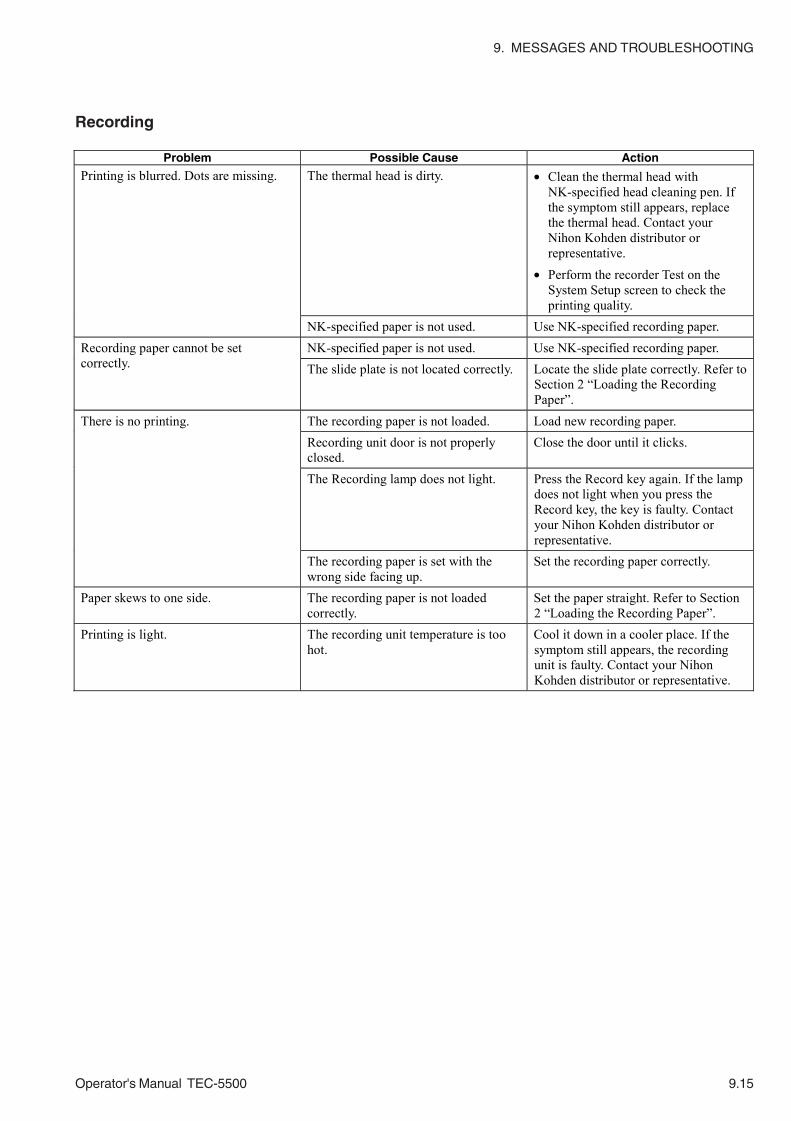
9. MESSAGES AND TROUBLESHOOTING
Operator's Manual TEC-5500 9.15
Recording
Problem Possible Cause Action
The thermal head is dirty. • Clean the thermal head with NK-specified head cleaning pen. If the symptom still appears, replace the thermal head. Contact your Nihon Kohden distributor or representative.
• Perform the recorder Test on the System Setup screen to check the printing quality.
Printing is blurred. Dots are missing.
NK-specified paper is not used. Use NK-specified recording paper. NK-specified paper is not used. Use NK-specified recording paper. Recording paper cannot be set
correctly. The slide plate is not located correctly. Locate the slide plate correctly. Refer to Section 2 “Loading the Recording Paper”.
The recording paper is not loaded. Load new recording paper. Recording unit door is not properly closed.
Close the door until it clicks.
The Recording lamp does not light. Press the Record key again. If the lamp does not light when you press the Record key, the key is faulty. Contact your Nihon Kohden distributor or representative.
There is no printing.
The recording paper is set with the wrong side facing up.
Set the recording paper correctly.
Paper skews to one side. The recording paper is not loaded correctly.
Set the paper straight. Refer to Section 2 “Loading the Recording Paper”.
Printing is light. The recording unit temperature is too hot.
Cool it down in a cooler place. If the symptom still appears, the recording unit is faulty. Contact your Nihon Kohden distributor or representative.
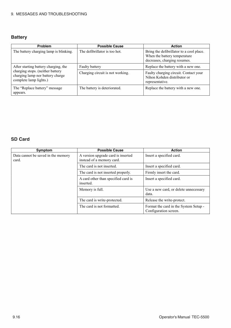
9. MESSAGES AND TROUBLESHOOTING
9.16 Operator's Manual TEC-5500
Battery
SD Card
Problem Possible Cause Action
The battery charging lamp is blinking. The defibrillator is too hot. Bring the defibrillator to a cool place. When the battery temperature decreases, charging resumes.
Faulty battery Replace the battery with a new one. After starting battery charging, the charging stops. (neither battery charging lamp nor battery charge complete lamp lights.)
Charging circuit is not working. Faulty charging circuit. Contact your Nihon Kohden distributor or representative.
The “Replace battery” message appears.
The battery is deteriorated. Replace the battery with a new one.
Symptom Possible Cause Action
Data cannot be saved in the memory card.
A version upgrade card is inserted instead of a memory card.
Insert a specified card.
The card is not inserted. Insert a specified card. The card is not inserted properly. Firmly insert the card.
A card other than specified card is inserted.
Insert a specified card.
Memory is full. Use a new card, or delete unnecessary data.
The card is write-protected. Release the write-protect. The card is not formatted. Format the card in the System Setup -
Configuration screen.

Operator's Manual TEC-5500 10C.1
Section 10 Maintenance
Cleaning, Disinfecting and Sterilization ............................................................................ 10.1
Defibrillator ............................................................................................................ 10.1
External Paddles .................................................................................................... 10.1
Internal Paddles ..................................................................................................... 10.2
Battery ................................................................................................................... 10.2
ECG Electrode Leads and ECG Connection Cable ............................................... 10.3
Disposal and Replacement .............................................................................................. 10.4
Battery ................................................................................................................... 10.4
Disposal of Battery Pack ............................................................................. 10.4
Replacing Battery Pack ............................................................................... 10.4
Disposable Pads .................................................................................................... 10.6
Lifetime ........................................................................................................ 10.6
Disposal ....................................................................................................... 10.6
ECG ....................................................................................................................... 10.6
Electrode Lifetime ........................................................................................ 10.6
Disposing of Electrodes ............................................................................... 10.6
Check After Use ............................................................................................................... 10.7
Periodical Checks ............................................................................................................ 10.8
Checking External Paddles .................................................................................... 10.8
Checking 270 J Energy Charge and Disarm ......................................................... 10.9
Battery Test .......................................................................................................... 10.10
Checking the Battery Appearance ....................................................................... 10.12
HV Capacitor Test ................................................................................................ 10.13
Recorder Test ...................................................................................................... 10.14
Date and Time Adjustment .................................................................................. 10.14
Periodical Replacement Schedule ................................................................................. 10.14
Repair Parts Availability Policy ....................................................................................... 10.14
Storage .......................................................................................................................... 10.15
Defibrillator and Battery ....................................................................................... 10.15
Short Term Storage (Ready for Use at Any Time) ..................................... 10.15
Long Term Storage .................................................................................... 10.15
Disposable Pads and ECG Electrodes ................................................................ 10.16

10C.2 Operator's Manual TEC-5500
This page is intentionally left blank.

10. MAINTENANCE
Operator's Manual TEC-5500 10.1
Cleaning, Disinfecting and Sterilization
CAUTIONBefore maintenance, cleaning or disinfection, turn the defibrillator
power off, disconnect the power cord from the AC socket and then
remove the battery from the defibrillator. Failure to follow this
instruction may result in electrical shock and defibrillator malfunction.
For SpO2 adapter, SpO2 probe, CO2 sensor cable and CO2 sensor, refer to each
operator’s manual.
CAUTION• Do not use the following chemicals to clean the defibrillator, pads
adaptor, ECG connection cable. These chemicals melt or crack the
plastic surface.
Thinner, Trichloroethylene, Carbon tetrachloride, Gasoline, Benzine,
Kerosene, Benzene, Toluene
• Do not put gauze moistened with physiological saline solution on the
paddle holders. This may cause rusting or discoloration of the
electrode plate of the external paddle and test electrode (metal parts
of the paddle holders).
Wipe the dirt from the exterior surface of the defibrillator and paddle holders and
the paste (GELAID) from the test electrodes with a soft cloth moistened with water
or disinfecting alcohol then wipe them with a clean and dry cloth.
CAUTION• Do not bend the connector pins of the external paddles. If pins are
bent, replace the paddle with a new one. With a bent pin, energy
cannot be discharged because of poor continuity.
• The external paddles cannot be sterilized.
• Do not heat the external paddles above 60°C (140°F) or put them in
liquid.
Wipe the paste (GELAID) from the electrodes and handles of the external paddles
with a soft cloth moistened with disinfecting alcohol then wipe them with a clean
and dry cloth.
Defibrillator
External Paddles

10. MAINTENANCE
10.2 Operator's Manual TEC-5500
CAUTION• Do not bend the connector pins of the internal paddles. If pins are
bent, replace the paddle with a new one. With a bent pin, energy
cannot be discharged because of poor continuity.
• Replace an internal paddle with a new one after about 100 times
autoclaving because the internal paddles can withstand up to 100
times autoclaving under the following conditions. More autoclaving
may cause cable discontinuity and damage the cable surface.
• Replace an internal paddle with a new one after about 100 times EOG
sterilization.
NOTEThe electrode and the handle cannot be separated.
Wipe dirt from the electrodes and handles of the internal paddles with a soft cloth
moistened with water or disinfecting alcohol then wipe them with a clean and dry
cloth.
After cleaning, sterilize the internal paddles by autoclaving or EOG (ethylene oxide
gas). The following sterilizing conditions are examples. Refer to the manual of the
sterilizing equipment.
EOG
Gas: EO 30% + CO2 70%
EO concentration: 940 mg/L
Temperature: 50°C, 122°F
Relative humidity: 50%
Pressure: 1 kg/cm2 (98 kPa )
Period: at least 4 hours
To remove the remaining gas from the paddles after sterilization, first decrease
the internal pressure of the sterilization equipment to − 760 mmHg with a
vacuum pump, then add carbon dioxide or antiseptic gas in the equipment.
Repeat this procedure (aeration) at least 5 times. Take the paddles out of the
sterilization equipment and do not use them for at least 20 days.
Autoclaving
Pressure 2.0 kg/cm2 (196 kPa)
Temperature 132°C (269.6°F)
Period 10 minutes
Internal Paddles
Remove dirt from the battery every 6 months.Battery

10. MAINTENANCE
Operator's Manual TEC-5500 10.3
Thoroughly wipe ECG electrode leads and an ECG connection cable with a soft
cloth moistened with water, neutral detergent or disinfecting alcohol.
To disinfect, wipe it with a soft cloth moistened with any of the disinfectants listed
below. Use the recommended concentration.
Disinfectant Concentration (%)
Glutaraldehyde solution 2.0
Hydrochloric alkyldiaminoethylglycine 0.5
Benzalkonium chloride 0.2
Benzethonium chloride solution 0.2
Chlorohexidine gluconate solution 0.5
ECG Electrode Leads andECG Connection Cable

10. MAINTENANCE
10.4 Operator's Manual TEC-5500
Disposal of Battery Pack
NOTEThe battery is NiMH. Before disposing of the battery, check with your
local solid waste officials for details in your area for recycling options
or proper disposal. The battery is recyclable. At the end of its useful
life, under various state and local laws, it may be illegal to dispose of
this battery into the municipal waste stream. Before disposing of the
defibrillator, remove the battery from the defibrillator.
Replacing Battery Pack
Replace the battery pack with a new one after one year.
NOTE• Use only the NKB-301V rechargeable battery.
• Write down the battery replacement date on the battery before
battery replacement.
• Battery replacement must be performed only by service staff.
1. On the new battery write the date when usage starts.
2. Confirm that the Energy/Mode Select control is set to OFF. Disconnect the
power cord from the defibrillator.
CAUTIONBefore battery replacement, turn off the defibrillator power and
disconnect the AC power cord from the defibrillator. Otherwise, the
operator may get an electrical shock.
NOTEWhile the “Shutdown NOW” message is displayed on the screen, do
not disconnect the power cord from the defibrillator or AC outlet and
do not remove the battery pack from the defibrillator. Otherwise, the
internal data may be damaged.
3. Turn the knob on the battery holder cover counterclockwise and remove the
battery pack holder cover.
Disposal and Replacement
Battery
10. MAINTENANCE
Operator's Manual TEC-5500 10.5
4. Disconnect the battery cable by holding the battery cable connector and
remove the battery from the defibrillator.
5. Insert the new battery into the battery pack holder.
6. Securely connect the battery connector to the connector inside the battery
pack holder until it clicks and locks.
7. Close the battery pack holder cover. Be careful not to pinch the cable. Secure
the battery pack holder cover by turning the knob clockwise.
8. On the battery check label, write the date when usage starts.
Attach the label on the defibrillator so that you can see them easily, for
example, on the upper part of the right side panel.
9. Reset the date of first use of the battery.
1) Display the System Setup - Battery Test screen.
2) Press the Reset key to reset the date of first use of the battery. The “Time
to replace battery” message appears one year after the Reset key is pressed.
NOTEYou must do this step when the battery is replaced. Otherwise, the
defibrillator does not display the “Time to replace battery” message to
prompt you to replace the battery.

10. MAINTENANCE
10.6 Operator's Manual TEC-5500
Disposable Pads
ECG
Lifetime
WARNING• Replace pads after 1 hour pacing.
• Do not use after expiration date.
CAUTIONFor long term ECG monitoring, replace pads every 24 hours.
Disposal
Follow your local laws for disposing of medical waste. To prevent second
infection, do not dispose of the disposable pads with other waste.
Electrode Lifetime
Replace the ECG disposable electrodes with new ones about every 24 hours.
Otherwise the contact impedance between the skin and electrode may increase due
to drying of the electrode gel or deterioration of adhesives and correct
measurement cannot be obtained.
If electrode contact becomes poor, replace it with a new one.
Disposing of Electrodes
Follow your local laws for disposing of medical waste. To prevent second
infection, do not dispose of the disposable pads with other waste.
For SpO2 adapter, SpO2 probe, CO2 sensor cable and CO2 sensor, refer to each
operator’s manual.

10. MAINTENANCE
Operator's Manual TEC-5500 10.7
Check After Use
To ensure correct performance for use in an emergency, check the following items
after every usage. If you find any trouble, check the defibrillator referring to
“Inspection” in this section and take necessary remedial actions. If any
abnormality is found, attach a “Not available” or “Repair requested” label on the
defibrillator and contact your Nihon Kohden distributor or representative.
Before turning off the power
• Temporarily changed settings on the System Setup screen and Setup screen are
returned to original settings.
• When the Energy/Mode Select control is set to DISARM position, “0 J” is
displayed on the screen.
• Energy is not still being charged.
• Cables are disconnected from the defibrillator.
Abnormality
• There was no abnormality during operation.
• No error indication is on the screen.
• The screen display is normal and can be seen clearly.
• The defibrillator is not too hot when touched.
• All settings are as you set them.
Appearance
• The defibrillator is not dirty or damaged.
• The metal plate of the paddle holder and paddle electrode is not rusted or
discolored.
• The operation panel and label on the defibrillator are not dirty or missing.
• There is no crack or damage on the defibrillator and paddles.
• There is no damage on the power cord.
• The battery check date and battery replacement date are not expired.
• Paddles are cleaned.
• Internal paddles are sterilized if necessary.
• There is enough paste (GELAID).
• If the defibrillator is in contact with liquid, it is wiped and dried thoroughly.
• Accessories are kept neatly.
• Disposable pads and ECG electrodes are disposed of properly so as not to cause
second infection.
• There are enough consumables such as recording paper.
• The power cord is connected to the defibrillator to maintain battery charge.
• The Energy/Mode Select control is set to OFF.
• There are no chemical solutions or water left around the defibrillator.
• The defibrillator storage condition is proper.

10. MAINTENANCE
10.8 Operator's Manual TEC-5500
CAUTION• Assembly and disassembly of any component in the instrument
should only be done by qualified service personnel.
• Before maintenance, cleaning or disinfection, turn the defibrillator
power off, disconnect the power cord from the AC socket and then
remove the battery from the defibrillator. Failure to follow this
instruction may result in electrical shock and defibrillator
malfunction.
Perform the Basic Checks every day. Refer to Section 2 “Basic Checks”.
Perform the following tests and checking once a month. If any abnormality is
found, contact your Nihon Kohden distributor or representative.
• Checking external paddles
• Basic Checks
• Checking 270 J energy charge and disarm
• Battery test
• HV capacitor test
• Recorder test
• Date and time adjustment
Check the battery appearance every 6 months.
To check the energy discharge, use the Basic Checks screen.
• Check that there is no crack or damage on the resin of external paddles and resin
of adult electrodes.
• Check that there is no scratch or damage on the cables and its mold part.
• Pull the DISCHARGE buttons on the APEX and STERNUM paddles. If the
button is pulled out, the button attachment is broken and replacement is
necessary.
• Check energy discharge. Check the operation of the CHARGE button and
DISCHARGE buttons. Confirm that there is no discontinuity in the cables.
Checking External Paddles
Periodical Checks

10. MAINTENANCE
Operator's Manual TEC-5500 10.9
Checking 270 J EnergyCharge and Disarm
Checks that the defibrillator automatically disarms.
1. Turn the Energy/Mode Select control to 270 J.
2. Leaving the paddles on their holders, press the CHARGE button on the APEX
paddle to start charging.
3. Confirm that there is a beeping sound, the “CHARGING” message appears on
the screen and the CHARGE lamp on the APEX paddle blinks.
4. When charging is completed, there is a continuous buzzing sound and the
CHARGE lamp lights. Confirm that the “CHARGED” message and “270 J” is
displayed on the screen.
5. Turn the Energy/Mode select control to the DISARM position.
6. Check that the energy value on the lower right of the screen changes to 0 J in
20 seconds. If not, contact your Nihon Kohden distributor or representative.
NOTE• Do not discharge manually by pressing the DISCHARGE buttons.
• If any error message appears during the test, contact your Nihon
Kohden distributor or representative.
• Do not continuously perform this check more than the specified
number of charge/discharge cycles. Refer to “Specification -
Defibrillator - Maximum continuous charge/discharge cycles at 270 J”
in Section 11.
10. MAINTENANCE
10.10 Operator's Manual TEC-5500
This checks the battery capacity by charging and discharging the battery. Perform
this test once a month.
WARNINGIf defibrillation or cardioversion is necessary during battery test,
cancel the battery test and operate the defibrillator on AC power. Do
not use battery power because the battery may have been discharged
by the battery test.
NOTE• It takes about 4.5 hours to test a fully charged new battery at the
20°C ambient temperature. It takes up to 6 hours to test a battery
which has little remaining charge.
• If the power cord is disconnected from the defibrillator during the
battery test, the battery test is canceled. Before starting the battery
test, firmly connect the power cord to the AC outlet on the wall and
the defibrillator.
• If there is a difference in temperature between the battery and the
defibrillator, the battery test cannot be done properly. In such a case
(for example, when you test the extra battery), insert the battery in
the defibrillator and leave it for 3 hours, then perform the battery test.
1. On the System Setup - Menu screen, select “Battery Test” with the Item key
and press the OK key. The System Setup - Battery Test screen appears.
2. Confirm that the battery is properly installed.
3. Connect the power cord to the AC outlet.
4. Confirm that enough recording paper is loaded in the recording unit. If not,
load it.
5. Press the START key to start the battery test.
• When the battery is not fully charged, it is charged, then discharged.
• When the battery is fully charged, it is immediately discharged.
A message shows the progress of the test.
Checking battery: Battery is being charged for the battery test.
Battery is being discharged.
Battery is being charged for the next use.
Test result XX %: Test finished.
NOTEWhen the battery temperature is high, an error message and the
battery test result appear on the screen, and the battery charging
Battery Test

10. MAINTENANCE
Operator's Manual TEC-5500 10.11
Reset:Press this key only when the battery pack is replaced. Referto “Inserting the Battery into the Defibrillator” in Section 2.
stops. With the power cord connected, turn the Energy/Mode Select
control to OFF to reduce the battery temperature, and make sure to
continue the battery charging for the next use. (Refer to “Error
Messages During Battery Test” table.)
To stop the battery test, press the STOP key.
6. When test finishes, the result appears on the screen.
Battery capacity is shown as 100, 80, 70, 60, 50, 40, and 0.
While the test result is displayed on the screen, you can print the test result by
pressing the Record key.
NOTE• Even when the capacity is 100 to 70%, replace a battery which has
been used for more than one year.
• When you cannot confirm the capacity (%) after battery test is done,
press the Record key to confirm that the battery test is correctly
done.
• Do not press any keys or buttons during battery test. Otherwise the
screen may switch to the setup screen by pressing the menu key.
Test result Description Action
Battery OK XXX% (Capacity XXX%:100%, 80% 70%)
Capacity is enough. Battery operation is available anytime. When the defibrillator is not used, always do trickle charging.
Battery WEAK XXX% Capacity XXX%: 60%, 50%)
Capacity has decreased under 70%.
Battery operation is available only when the battery is fully charged. The time to replace the battery is coming soon. It is recommended that the battery be replaced with a new one.
Replace battery XXX% (Capacity XXX%: 40%, 0%)
Capacity has decreased under 50%.
Only AC operation is available. Immediately replace the battery with a new one. Contact your Nihon Kohden distributor or representative.

10. MAINTENANCE
10.12 Operator's Manual TEC-5500
Error Messages During Battery Test
Checking the BatteryAppearance
7. Press the Menu key to return to the System Setup - Menu screen.
To prevent battery trouble, check the battery appearance every 6 months. The
check schedule should be written on the battery check label attached to the
defibrillator.
1. Check the outside appearance of the battery pack. If there is any damage
(crack, deformation, cable discontinuity and so on) on the battery or the battery
leaks, replace the battery with a new one. If the battery is dirty with dust,
remove it.
If the battery check label says it is the day to replace the battery, replace the
battery with a new one.
2. After checking, change the battery check label. If the battery is replaced, write
down the date of the first use on the new battery.
Message Description Action
Insert battery Battery test cannot be done because the battery is not inserted in the defibrillator.
First disconnect the power cord and then insert the battery into the defibrillator. Do the test again.
Connect to AC power Battery test cannot be done because AC power is not supplied to the defibrillator.
Supply AC power to the defibrillator and do the test again.
Battery discharge timed out A battery other than the specified one is used. Or defibrillator abnormality.
Battery charge timed out A battery other than the specified one is used. Or the battery is deteriorated.
Use the specified battery pack. If the message still appears, contact your Nihon Kohden distributor or representative.
Battery charging error Faulty defibrillator Contact your Nihon Kohden distributor or representative.
Battery FET Error Faulty defibrillator Contact your Nihon Kohden distributor or representative.
Battery charging stopped due to increased temperature. Turn Energy/Mode Select to OFF to charge battery
The battery temperature is high and the battery charging stops.
With the power cord connected, turn the Energy/Mode Select control to OFF, and continue the battery charging for the next use.

10. MAINTENANCE
Operator's Manual TEC-5500 10.13
HV Capacitor Test This checks the performance of the HV (high voltage) capacitor to charge the
defibrillation energy. During this check, the capacitor is charged and disarms.
NOTEMake sure that the AC power cord is connected to ensure the battery
charge for emergency operation.
1. On the System Setup - Menu screen, select “HV Capacitor Test” with the Item
key and press the OK key. The System Setup - HV Capacitor Test screen
appears.
2. Set the Energy/Mode Select control to 200 J.
NOTEIf the energy is not set to 200 J, HV capacitor test cannot be done.
3. Press the CHARGE button on the external paddle (APEX) or the CHARGE/
AED button on the front panel to charge energy. The defibrillator charges the
selected energy. After charging is completed, the defibrillator automatically
disarms and measures the discharge energy. The check result appears on the
screen.
NOTEDuring charging, if the Energy/Mode Select control is turned to another
position, the defibrillator immediately disarms.
4. Press the key for “Menu” to return to the System Setup-Menu screen.
Test result Description
Capacitance XXX% Capacitor test pass
100 – 80 %: Capacitor performance is OK. It can be used at any time.
Capacitance XXX% Capacitor test fail
0 – 79 %: Capacitor life is almost over. Replace it with a new one. Contact your Nihon Kohden distributor or representative.

10. MAINTENANCE
10.14 Operator's Manual TEC-5500
Recorder Test
Date and Time Adjustment Confirm that the date and time printed on the recording paper is correct.
If it is not correct, set the date and time on the Date/Volume screen. Refer to
Section 3.
NOTEMake sure that the date and time printed on the recording paper is
correct. The date and time on the recording paper are important parts
of the medical record.
The built-in recorder can be checked by recording the preset waveforms and
alphanumeric characters. Perform this test once a month.
NOTEMake sure that the AC power cord is connected to ensure the battery
charge for emergency operation.
1. On the System Setup - Menu screen, select “Recorder Test” with the Item and
press the OK key. The recorder starts printing the preset waveforms and
characters.
To cancel printing, press the Record key.
2. Check the printed paper. Confirm that there is no problem in printing.
Repair Parts Availability Policy
Periodical Replacement Schedule
To maintain the performance of the defibrillator, the following part must be
periodically replaced.
Battery pack, NKB-301V Every year
Pad adaptor, JC-765V (option for P-510/512 pads) Every two years
Pad adaptor, JC-755V (option for R2 pads) Every two years
Nihon Kohden Corporation (NKC) shall stock repair parts (parts necessary to
maintain the performance of the instrument) for a period of 8 years from the date of
delivery. In that period NKC or its authorized agents will repair the instrument.
This period may be shorter than 8 years if the board or part necessary for the faulty
section is not available.
10. MAINTENANCE
Operator's Manual TEC-5500 10.15
Storage
Before storage, clean the defibrillator, cables and paddles as described in
“Cleaning” in this section. When disposable pads or internal paddles are connected
to the defibrillator, disconnect them and connect external paddles to the
defibrillator.
Short Term Storage (Ready for Use at Any Time)
CAUTIONTo prevent overheating, leave the defibrillator lying flat and do not
cover it.
• When the defibrillator is not used, always connect it to AC power to maintain the
battery charge with trickle charging. Confirm that the AC lamp is on.
• Check the battery appearance every 6 months and do the battery test every
month.
• Store in a cool place (–20 to 35°C, –4 to 95°F). If the defibrillator is stored in
high temperature, the battery deteriorates.
Long Term Storage
• If you store the defibrillator not connected to AC power, remove the battery from
the defibrillator. Otherwise, the battery over-discharged after 1 month in the
defibrillator without AC power.
• When you store a battery outside the defibrillator, do the battery test every 6
months.
• Store the battery and defibrillator in a cool place (–20 to 35°C, –4 to 95°F). If
the battery is stored at high temperature, it deteriorates.
Defibrillator and Battery
NOTEThe operating environment must be more than 0oC. (Refer to
“Specifications” in Section 11.) Otherwise the high voltage capacitor
may get damaged. If the defibrillator was stored below –5oC, leave it
for 3 hours or more in at least 0oC before using it.

10. MAINTENANCE
10.16 Operator's Manual TEC-5500
CAUTION• Store the disposable pads in an environment described on the pads
package. If stored in an environment other than specified, the pads
become unusable.
• Do not put heavy thing on pads or do not bend pads. Pads get
damaged and deteriorated, and may cause burn to the patient.
• Store the disposable pads and ECG electrodes in a cool place (5 to 35°C, 41 to
95°F).
• Each pad has its own lifetime. Use the pad within its lifetime.
• Do not put heavy thing on pads and ECG electrodes. Otherwise, the gel may
flow out.
Disposable Pads and ECGElectrodes
Operator's Manual TEC-5500 11C.1
Section 11 Reference
Specifications ................................................................................................................... 11.1
Defibrillator .................................................................................................... 11.1
Noninvasive Pacing (TEC-5531 series only) ................................................. 11.3
External Paddle (ND-552VB/VE/VK) ............................................................. 11.3
Battery .......................................................................................................... 11.3
Clock Accuracy ............................................................................................. 11.3
Environment .................................................................................................. 11.3
Safety ........................................................................................................... 11.4
Monitor .......................................................................................................... 11.4
ECG Amplifier ............................................................................................... 11.4
Recorder ........................................................................................................ 11.5
Rhythm Recognition Detector ....................................................................... 11.5
Power Requirements ..................................................................................... 11.5
Dimensions and Weight ................................................................................. 11.5
Electromagnetic Compatibility ....................................................................... 11.6
Reference ........................................................................................................................ 11.10
Standard Accessories ..................................................................................................... 11.11
Options/Consumables ..................................................................................................... 11.12
Pin Assignment ............................................................................................................... 11.14
AUX Connector of the QI-553V DSI/AUX OUT Interface Unit ................................ 11.14
General Requirements for Connecting Medical Electrical System ................................... 11.15

11C.2 Operator's Manual TEC-5500
This page is intentionally left blank.

11. REFERENCE
Operator's Manual TEC-5500 11.1
Specifications
Defibrillator
Output energy (across 50 Ω) 2, 3, 5, 7, 10, 15, 20, 30, 50, 70, 100, 150, 200 and 270 J
Energy accuracy 2 J: ±0.5 J, 3 J: ±1 J,5 to 15 J: ±2 J, 20 to 270 J: ±10%
Output waveform Biphasic, truncated exponential constant power (across 50 Ω)
Charging time
Manual modeWhen powered by AC 100V to 240V: to 270 J, maximum 5 s
to 200 J, maximum 3 sWhen powered by 90% of the rated mains voltage: to 270 J, maximum 5 sWhen powered by a fully charged new battery at 20°C ambienttemperature:
to 270 J, maximum 5 sto 200 J, maximum 3 s
After 15 discharges at 270 J with a fully charged new battery at 20°Cambient temperature:
to 270 J, maximum 5 s
When powered by 90% of the rated mains voltage or after 15 dischargesat 270 J with a fully charged new battery at 20°C ambient temperature:
Power on to 270 J, maximum 7 s
AED modeWhen powered by 90% of the rated mains voltage or after 15 dischargesat 270 J with a fully charged new battery at 20°C ambient temperature:
Power on to 270 J:typical 17 s, maximum 31 sStandby mode to 270 J:typical 15 s, maximum 29 s
Charging display Displays the charged energy value on the screen
Synchronized discharge Available
From the peak of R wave to the peak of discharge: within 60 ms
Maximum continuous charge/discharge cycles at 270 J
20 cycles: 3 cycles per minute with 1 minute cool down period after every 1 minute charge/
discharge period
15 cycles: 3 cycles per minute with no cool down period
Maximum skin-disposable pad contact impedance for energy charging: 280 Ω
Delivered energy : 270 J
First phase Second phase Load resistance (Ω) Ipk1 (A) D1 (ms) Ipk2 (A) D2 (ms) 25 67.3 3.85 15.5 3.62 50 41.1 6.35 12.7 3.62 75 29.5 8.86 11.0 3.62
100 22.9 11.4 9.81 3.62 125 18.8 13.9 8.96 3.62 150 15.9 16.4 8.29 3.62 175 13.8 18.9 7.76 3.62

11. REFERENCE
11.2 Operator's Manual TEC-5500
curr
ent [
A]
time [ms]
25
60
40
20
-20
0
0 2 64 8 10 12 14 16 18 20 22 24
50
60
40
20
-20
0
0 2 64 8 10 12 14 16 18 20 22 24
curr
ent [
A]
time [ms]
75
60
40
20
-20
0
0 2 64 8 10 12 14 16 18 20 22 24
curr
ent [
A]
time [ms]
100
30
20
10
-10
0
0 2 64 8 10 12 14 16 18 20 22 24
curr
ent [
A]
time [ms]
125
30
20
10
-10
0
0 2 64 8 10 12 14 16 18 20 22 24
curr
ent [
A]
time [ms]
150
30
20
10
-10
0
0 2 64 8 10 12 14 16 18 20 22 24
curr
ent [
A]
time [ms]
175
30
20
10
-10
0
0 2 64 8 10 12 14 16 18 20 22 24
curr
ent [
A]
time [ms]

11. REFERENCE
Operator's Manual TEC-5500 11.3
Noninvasive Pacing (TEC-5531 series only)
Pacing rate 40 to 180 pulse/min in 10 pulse/min steps
Output current 8 to 200 mA in 1, 2, 5 or 10 mA steps (Set on the System Setup screen)
Pacing modes Fixed and Demand
Maximum load resistance Outputs 200 mA across 250 Ω, 120 mA across 500 Ω
External Paddle (ND-552VB/VE/VK)
Paddle electrode size For adults: 70 ±3 × 10⁶ ±3 (mm2)
For children: 45 ±3 × 53 ±3 (mm2)
Paddle cord length 2.0 m or more (when it is pulled by 18 N force)
Battery
Type
Ni-MH battery Nominal voltage: 12 V
Rated capacity: 2800 mAh
Capacity With fully charged new battery at 20°C ambient temperature
• Minimum 70 discharges at 270 J
• Minimum 150 minutes continuous monitoring
• Minimum 90 minutes fixed mode pacing (180 pulse/min, 200 mA)
With the fully charged new battery at 0°C, the defibrillator can perform:
• Minimum 50 discharges at 270 J
Clock Accuracy
At surrounding temeprature 25°C (77°F): ±3 min/month
At storage temperatures -20 to 70°C (–4 to 158°F): ±5 min/month
Environment
Operating temperature 0 to 45°C (32 to 113°F)
Operating humidity 30 to 95% (relative humidity, non-condensing)
Operating atmospheric pressure 700 to 1060 hPa
(Recording paper may jam, if it is wet.)
Storage temperature –20 to 70°C (–4 to 158°F)
Storage humidity 10 to 95% (relative humidity)
Storage atmospheric pressure 500 to 1060 hPa

11. REFERENCE
11.4 Operator's Manual TEC-5500
Safety
Safety standard IEC 60601-1: 1988
IEC 60601-1 Amendment 1: 1991
IEC 60601-1 Amendment 2: 1995
IEC 60601-1-2: 2001
IEC 60601-2-4: 2002
According to the type of protection against electrical shock
Battery power: INTERNALLY POWERED EQUIPMENT
AC power: CLASS I EQUIPMENT
According to the degree of protection against electrical shock
DEFIBRILLATION-PROOF TYPE BF APPLIED PART
External paddles, disposable pads, SpO2 adapter and CO
2 sensor kit
DEFIBRILLATION-PROOF TYPE CF APPLIED PART
Internal paddles, ECG connection cable
According to the degree of protection against harmful ingress of water IPX1
According to the degree of safety of application in the presence of a FLAMMABLE ANAESTHETIC MIXTURE
WITH AIR, OR WITH OXYGEN OR NITROUS OXIDE
EQUIPMENT not suitable for use in the presence of FLAMMABLE
ANAESTHETIC MIXTURE WITH AIR, OR WITH OXYGEN OR NITROUS
OXIDE
Mode of operation Continuous operation with intermittent load
: Operation at defibrillation mode
Continuous operation
: All operation except above mentioned
Monitor
Effective display area 117.2(W) × 88.4(H) mm (5.7 inch)
Sweep length 97 mm
Sweep speed 25 mm/s, 50 mm/s
Sensitivity 10 mm/1mV ±5% (sensitivity ×1)
Amplitude limit 40 mm
ECG Amplifier
Input signal PADDLE, I, II, III, aVR, aVL, aVF, V, AUX
Frequency response Through paddles: 0.5 to 20 Hz (-3 dB)
Through ECG connection cable: 0.05 to 150 Hz (-3 dB)
AUX: 0.05 to 150 Hz (-3 dB)
Input impedance Through paddles: ≥100 kΩThrough ECG connection cable: ≥ 5 MΩ(at 10 Hz 1mV)
AUX: ≥100 kΩ ±10%
CMRR ≥100 dB (against chassis ground) when AC filter is ON
AC filter Available (common with 50/60 Hz)
ON at ≥-20 dB, OFF
Pacing pulse rejection ON, OFF
External ECG input sensitivity 10 mm/V ± 5% (sensitivity ×1)
Heart rate counting range Defibrillation or monitoring mode: 15 to 300 bpm
Pacing mode: 15 to 220 bpm

11. REFERENCE
Operator's Manual TEC-5500 11.5
Recorder
Paper speed Real time/delayed ECG waveform recording: 50, 25 mm/s
Types of recording
Manual recording: real time/delayed waveform recording, report recording, event recording
Automatic recording: record on charging after discharge, alarm recording, periodic recording
Rhythm Recognition Detector
We evaluated the rhythm recognition detector of the TEC-5500 series defibrillator using the official electrocardiogram
database provided by AHA (American Heart Association) and MIT (Massachusetts Institute of Technology) and an
electrocardiogram database of over 3000 electrocardiograms from hospitals in Japan. According to our own
evaluation, the rhythm recognition detector of the TEC-5500 series defibrillator meets the equivalent of AAMI
standards ANSI/AAMI DF-39-1993 3.3.18.
Shockable Rhythm VF Sensitivity : ≥ 90%
Shockable Rhythm VT Sensitivity: ≥ 75%
All other Non-Shockable Rhythm Sensitivity: ≥ 95%
Power Requirements
AC
Line voltage 100 to 240 V
Line frequency 50/60 Hz (automatic switching)
Power input Intermittent load: 450 VA or less
Continuous load: 200 VA or less
DC (Battery)
Power voltage 12 V
Power consumption Intermittent load: 18 A or less
Continuous load: 4.2 A or less
Charging time 3 hours or less (with AC, with the power OFF)
Dimensions and Weight
Dimensions 290 (W) × 172 (H) × 355 (D) mm
Weight
TEC-5521 series defibrillator 6.1 kg (External paddles use, AC unit without battery)
5.3 kg (Pad adaptor use, AC unit without battery)
TEC-5531 series defibrillator 6.3 kg (External paddles use, AC unit without battery)
5.5 kg (Pad adaptor use, AC unit without battery)

11. REFERENCE
11.6 Operator's Manual TEC-5500
Standard
IEC 60601-1-2: 2001
Medical electrical equipment - Part 1-2: General requirements for safety - Collateral standard: Electromagnetic
compatibility - Requirements and tests
IEC 60601-2-4: 2002
Medical electrical equipment - Part 2-4: Particular requirement for the safety of cardiac defibrillators
Electromagnetic Emissions/Immunity Ccompliance Level and Guidance
Electromagnetic Compatibility
Guidance and manufacturer's declaration - electromagnetic emissions The TEC-5500 series is intended for use in the electromagnetic environment specified below. The customer or the user of the TEC-5500 series should assure that it is used in such an environment.
Emissions test Compliance Electromagnetic environment - guidance
RF emissions CISPR 11 Group 1
The TEC-5500 series uses RF energy only for its internal function. Therefore, its RF emissions are very low and are not likely to cause any interference in nearby electronic equipment.
RF emissions CISPR 11 Class B Harmonic emissions IEC 61000-3-2 Class A Voltage fluctuations/ flicker emissions IEC 61000-3-3
Complies
The TEC-5500 series is suitable for use in all establishments, including domestic establishments and those directly connected to the public low-voltage power supply network that supplies buildings used for domestic purposes.
Guidance and manufacturer's declaration - electromagnetic immunity The TEC-5500 series is intended for use in the electromagnetic environment specified below. The customer or the user of the TEC-5500 series should assure that it is used in such an environment.
Immunity test IEC 60601 test level Compliance level Electromagnetic environment — guidance
Electrostatic discharge (ESD) IEC 61000-4-2
±6 kV contact ±8 kV air
±6 kV contact ±8 kV air
Floors should be wood, concrete or ceramic tile. If floors are covered with synthetic material, the relative humidity should be at least 30 %.
Electrical fast transient/burst IEC 61000-4-4
±2 kV for power supply lines
±2 kV for power supply lines
Mains power quality should be that of a typical commercial or hospital environment.
Surge IEC 61000-4-5
±1 kV differential mode ±2 kV common mode
±1 kV differential mode ±2 kV common mode
Mains power quality should be that of a typical commercial or hospital environment.
Voltage dips, short interruptions and voltage variations on power supply input lines IEC 61000-4-11
<5% Ut (>95 % dip in Ut) for 0.5 cycles 40% Ut (60% dip in Ut) for 5 cycles 70% Ut (30% dip in Ut) for 25 cycles
<5% Ut (>95% dip in Ut) for 0.5 cycles 40% Ut (60 % dip in Ut) for 5 cycles 70% Ut (30% dip in Ut) for 25 cycles
Mains power quality should be that of a typical commercial or hospital environment. If the user of the TEC-5500 series requires continued operation during power mains interruptions, it is recommended that the TEC-5500 series be powered from an uninterruptible power supply or a battery.
Voltage dips, short interruptions and voltage variations on power supply input lines IEC 61000-4-11
<5% Ut (>95 % dip in Ut) for 5 seconds
<5% Ut (>95 % dip in Ut) for 5 seconds
Mains power quality should be that of a typical commercial or hospital environment. If the user of the TEC-5500 series requires continued operation during power mains interruptions, it is recommended that the TEC-5500 series be powered from an uninterruptible power supply or a battery.
Power frequency (50/60 Hz) magnetic field IEC 61000-4-8
3 A/m 3 A/m Power frequency magnetic fields should be at levels characteristic of a typical location in a typical commercial or hospital environment.
NOTE: Ut is the AC mains voltage prior to application of the test level.
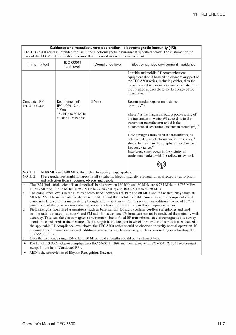
11. REFERENCE
Operator's Manual TEC-5500 11.7
Guidance and manufacturer's declaration - electromagnetic immunity (1/2) The TEC-5500 series is intended for use in the electromagnetic environment specified below. The customer or the user of the TEC-5500 series should assure that it is used in such an environment.
Immunity test IEC 60601 test level Compliance level Electromagnetic environment - guidance
Conducted RF IEC 61000-4-6
Requirement of IEC-60601-2-4: 3 Vrms 150 kHz to 80 MHz outside ISM bandsa
3 Vrms
Portable and mobile RF communications equipment should be used no closer to any part of the TEC-5500 series, including cables, than the recommended separation distance calculated from the equation applicable to the frequency of the transmitter. Recommended separation distance d = 1.2√P where P is the maximum output power rating of the transmitter in watts (W) according to the transmitter manufacturer and d is the recommended separation distance in meters (m). b Field strengths from fixed RF transmitters, as determined by an electromagnetic site survey, c should be less than the compliance level in each frequency range. d Interference may occur in the vicinity of equipment marked with the following symbol:
NOTE 1: At 80 MHz and 800 MHz, the higher frequency range applies. NOTE 2: These guidelines might not apply in all situations. Electromagnetic propagation is affected by absorption
and reflection from structures, objects and people. a: The ISM (industrial, scientific and medical) bands between 150 kHz and 80 MHz are 6.765 MHz to 6.795 MHz;
13.553 MHz to 13.567 MHz; 26.957 MHz to 27.283 MHz; and 40.66 MHz to 40.70 MHz. b: The compliance levels in the ISM frequency bands between 150 kHz and 80 MHz and in the frequency range 80
MHz to 2.5 GHz are intended to decrease the likelihood that mobile/portable communications equipment could cause interference if it is inadvertently brought into patient areas. For this reason, an additional factor of 10/3 is used in calculating the recommended separation distance for transmitters in these frequency ranges.
c: Field strengths from fixed transmitters, such as base stations for radio (cellular/cordless) telephones and land mobile radios, amateur radio, AM and FM radio broadcast and TV broadcast cannot be predicted theoretically with accuracy. To assess the electromagnetic environment due to fixed RF transmitters, an electromagnetic site survey should be considered. If the measured field strength in the location in which the TEC-5500 series is used exceeds the applicable RF compliance level above, the TEC-5500 series should be observed to verify normal operation. If abnormal performance is observed, additional measures may be necessary, such as re-orienting or relocating the TEC-5500 series.
d: Over the frequency range 150 kHz to 80 MHz, field strengths should be less than 3 V/m. • The JL-951T3 SpO2 adapter complies with IEC 60601-2: 1993 and it complies with IEC 60601-2: 2001 requirement
except for the item “Conducted RF”. • RRD is the abbreviation of Rhythm Recognition Detector.

11. REFERENCE
11.8 Operator's Manual TEC-5500
Guidance and manufacturer's declaration - electromagnetic immunity (2/2) The TEC-5500 series is intended for use in the electromagnetic environment specified below. The customer or the user of the TEC-5500 series should assure that it is used in such an environment.
Immunity test IEC 60601 test level Compliance level Electromagnetic environment - guidance
Radiated RF IEC 61000-4-3
Requirement of IEC-60601-2-4: Correct operation of RRD: 10 V/m 80 MHz to 2.5 GHz No inadvertent energy delivery is allowed: 20 V/m 80 MHz to 2.5 GHz
3 V/m 20 V/m
Portable and mobile RF communications equipment should be used no closer to any part of the TEC-5500 series , including cables, than the recommended separation distance calculated from the equation applicable to the frequency of the transmitter. Recommended separation distance d = 1.2√P 80 to 800 MHz d = 2.3√P 800 MHz to 2.5 GHz Additional requirement of IEC 60601-2-4 Correct operation of RRD: d = 4.0√P 80 to 800 MHz d = 7.7√P 800 MHz to 2.5 GHz No inadvertent energy delivery is allowed: d = 0.6√P 80 to 800 MHz d = 1.2√P 800 MHz to 2.5 GHz where P is the maximum output power rating of the transmitter in watts (W) according to the transmitter manufacturer and d is the recommended separation distance in meters (m). b Field strengths from fixed RF transmitters, as deter mined by an electromagnetic site survey, c should be less than the compliance level in each frequency range. d Interference may occur in the vicinity of equipment marked with the following symbol:
NOTE 1: At 80 MHz and 800 MHz, the higher frequency range applies. NOTE 2: These guidelines might not apply in all situations. Electromagnetic propagation is affected by absorption
and reflection from structures, objects and people. a: The ISM (industrial, scientific and medical) bands between 150 kHz and 80 MHz are 6.765 MHz to 6.795 MHz;
13.553 MHz to 13.567 MHz; 26.957 MHz to 27.283 MHz; and 40.66 MHz to 40.70 MHz. b: The compliance levels in the ISM frequency bands between 150 kHz and 80 MHz and in the frequency range 80
MHz to 2.5 GHz are intended to decrease the likelihood that mobile/portable communications equipment could cause interference if it is inadvertently brought into patient areas. For this reason, an additional factor of 10/3 is used in calculating the recommended separation distance for transmitters in these frequency ranges.
c: Field strengths from fixed transmitters, such as base stations for radio (cellular/cordless) telephones and land mobile radios, amateur radio, AM and FM radio broadcast and TV broadcast cannot be predicted theoretically with accuracy. To assess the electromagnetic environment due to fixed RF transmitters, an electromagnetic site survey should be considered. If the measured field strength in the location in which the TEC-5500 series is used exceeds the applicable RF compliance level above, the TEC-5500 series should be observed to verify normal operation. If abnormal performance is observed, additional measures may be necessary, such as re-orienting or relocating the TEC-5500 series.
d: Over the frequency range 150 kHz to 80 MHz, field strengths should be less than 3 V/m.

11. REFERENCE
Operator's Manual TEC-5500 11.9
System Configuration at EMC testing
We tested that the defibrillator complies with IEC 60601-1-1: 2001 and IEC 60601-2-4: 2002 with the following
configuration. If other cables and equipments are used with the defibrillator, the defibrillator may not comply
with these standards.
Recommended separation distances between portable and mobile RF communications equipment and the TEC-5500 series
The TEC-5500 series is intended for use in an electromagnetic environment in which radiated RF disturbances are controlled. The customer or the user of the TEC-5500 series can help prevent electromagnetic interference by maintaining a minimum distance between portable and mobile RF communications equipment (transmitters) and the TEC-5500 series as recommended below, according to the maximum output power of the communications equipment.
Separation distance according to frequency of transmitter (m) Rated maximum output
power of transmitter (W)
150 kHz to 80 MHz outside ISM bands
d = 1.2√P
150 kHz to 80 MHz in ISM bands
d = 1.2√P
80 MHz to 800 MHz d = 4.0√P
800 MHz to 2.5 GHz d = 7.7√P
0.01 0.12 0.12 0.4 0.77 0,1 0.38 0.38 1.3 2.4 1 1.2 1.2 4.0 7.7
10 3.8 3.8 13 27 100 12 12 40 77
For transmitters rated at a maximum output power not listed above, the recommended separation distance d in meters (m) can be determined using the equation applicable to the frequency of the transmitter, where P is the maximum output power rating of the transmitter in watts (W) according to the transmitter manufacturer. NOTE 1: At 80 MHz and 800 MHz, the separation distance for the higher frequency range applies. NOTE 2: The ISM (industrial, scientific and medical) bands between 150 kHz and 80 MHz are 6.765 MHz to 6.795 MHz;
13.553 MHz to 13.567 MHz; 26.957 MHz to 27.283 MHz; and 40.66 MHz to 40.70 MHz. NOTE 3: An additional factor of 10/3 is used in calculating the recommended separation distance for transmitters in the
ISM frequency bands between 150 kHz and 80 MHz and in the frequency range 80 MHz to 2.5 GHz to decrease the likelihood that mobile/portable communications equipment could cause interference if it is inadvertently brought into patient areas.
NOTE 4: These guidelines might not apply in all situations. Electromagnetic propagation is affected by absorption and reflection from structures, objects and people.
The equations and values in the above table show the condition that the RRD (Rhythm Recognition Detector) regulated in IEC 60601-2-4: 2002 does not receive electromagnetic interference.
Configuration at testing Cable length (m) Defibrillator, TEC-5521/5531 series - DSI interface unit, QI-552V - External paddles, ND-552V 0.406 Pad adapter, JC-765V** 3.50 ECG connection cable, BC-763V 3.30 CO2 sensor kit, TG-901T3 2.99 SO2 adapter, JL-951T3* 2.50 Finger probe, TL-201T* 1.60 Battery pack, NKB-301V (YZ-024H9) - Holter card, QM-064D - * When the SpO2 adapter and finger probe are connected to
the defibrillator, the defibrillator does not comply with the item “Conducted RF” (IEC 60601-1-2: 2001).
** When the pad adapter is connected to the defibrillator, the compliance level of the item “Radiated RF” (IEC 60601-2-4:2002) is 3 V/m.

11. REFERENCE
11.10 Operator's Manual TEC-5500
Reference
1. KERBER, RE, CARTER, J., KLEIN, S, et al.
Open chest defibrillation during cardiac surgery: Energy and current
requirements.
American Journal of Cardiology, 46:393-396, 1980
2. RACKER, WA, GUINN, GA, GEDDES, LA, et al.
The electrical dose for direct ventricular defibrillation in man.
Journal of Thoracic Cardiovascular Surgery, 75:224-226, 1978
3. RUBIO, PA and FARRELL, EM.
Low-energy direct defibrillation of the human heart
Annals of Thoracic Surgery, 27:32-33, 1979

11. REFERENCE
Operator's Manual TEC-5500 11.11
Standard Accessories
NOTEWhen you order accessories/consumables which have a supply code
No., specify the supply code No., not the model or code No.
No. Name Q’ty Model or Code No. Supply Code No.
1 Recording paper (Z-fold) 1 FQS50-2-100 A226 2 Contact gel GELAID 1 --- F015
3 Battery check label (for defibrillator)
1 6124-022441 ---

11. REFERENCE
11.12 Operator's Manual TEC-5500
Options/Consumables
Name Q’ty Model or Code No. Supply code No.
TEC accessory set (100V/IEC) BC-763V ECG connection cable (IEC, 3 leads) + Power cord H
1 YZ-024H3 ---
TEC accessory set (200V/IEC) BC-763V ECG connection cable (IEC, 3 leads) + Power cord N
1 YZ-024H4 ---
TEC accessory set (100V/AHA) BC-763VA ECG connection cable (AHA, 3 leads) + Power cord H
1 YZ-024H5 ---
TEC accessory set (200/AHA) BC-763VA ECG connection cable (AHA, 3 leads) + Power cord N
1 YZ-024H6 ---
ECG connection cable (IEC, 3 leads) 1 BC-763V K353A ECG connection cable (AHA, 3 leads) 1 BC-763VA K352A ECG connection cable (IEC, 5 leads) 1 BC-765V K353B ECG connection cable (AHA, 5 leads) 1 BC-765VA K352B External ECG cable 1 JC-761V L151 Connection cable 1 JC-762V L152 Connection cable 1 JC-763V L153 Pad adaptor for P-510/P-520 1 JC-765V --- Pad adaptor for R2 pads 1 JC-755V --- Battery pack NKB-301V 1 YZ-024H9 X065 Power cord type N 1 314839B L936 Power cord type H 1 186656A L935 Ground lead type E 1 544582B --- Cart 1 KD-028A --- Cart tray assembly (option for the cart) 1 DI-001A --- Recording paper (roll) 1 RQS50-2-100 A226 Paste holder kit 1set YZ-025H0 ---
Disposable ECG electrode Vitrode C 150/set --- G204 Disposable pad for adult 1set P-510 H315 Disposable pad for child 1set P-512 H316
Internal paddle electrode, 25 mm φ 1set ND-762V ---
Internal paddle electrode, 35 mm φ 1set ND-763V ---
Internal paddle electrode, 45 mm φ 1set ND-764V ---
Internal paddle electrode, 55 mm φ 1set ND-765V ---
Internal paddle electrode, 65 mm φ 1set ND-766V ---
Internal paddle electrode, 75 mm φ 1set ND-767V ---
Pediatric electrode assy, 44 mm φ 1 ND-612V --- DSI interface unit 1 QI-552V --- DSI/AUX out interface unit 1 QI-553V --- Holter card (SD memory card) 1 QM-064D ---

11. REFERENCE
Operator's Manual TEC-5500 11.13
CAUTIONOnly use the KD-028A cart for this defibrillator. If another cart is used,
it may tip over or the defibrillator may fall off.
The ND-762V, 763V, 764V and 765V internal paddle do not comply with IEC
60601-2-4 56.101 standard for contact area for adult use. The ND-762V internal
paddle does not comply with IEC 60601-2-4 56.101 standard for contact area for
pediatric use.
There are two types of TG-921T3 CO2 sensor kit. One complies with IEC 60601-
1-2: 2001, the other does not. CO2 sensor kits which comply with this standard
have a IEC 60601-1-2: 2001 stamp. The defibrillator only complies with this
standard used with the CO2 sensor kit which complies with this standard.
Name Q’ty Model or Code No. Supply code No.
CO2 measurement CO2 sensor kit 1 TG-901T3 P906 Airway adapter 50/set YG-101T R801 CO2 sensor kit 1 TG-921T3 P908 Nasal Adapter (for nasal breathing) 30/set YG-120T V921 Nasal Adapter (for naso-oral breathing) 30/set YG-121T V922 Nasal Adapter (for oxygen cannula adjustment) 30/set YG-122T V923 SpO2 measurement SpO2 adapter 1 JL-951T3 Y090
Finger probe BluPRO 1 TL-201T P225F
Multi-site probe BluPRO 1 TL-220T P225G Multi-site Y prove 1 TE-260T P205A
SpO2 probe (for adult) (1.6 m) BluPRO 5/pcs TL-251T P201A
SpO2 probe (for child) (1.6 m) BluPRO 5/pcs TL-252T P201B
SpO2 probe (for neonate) (1.6 m) BluPRO 5/pcs TL-253T P201C
SpO2 probe (for adult and neonate) (0.8 m) 5/pcs TL-051S P228A
SpO2 probe (for adult and neonate) (1.6 m) 5/pcs TL-052S P228B
SpO2 probe (for adult, child and infant) (0.8 m) 5/pcs TL-061S P229A
SpO2 probe (for adult, child and infant) (1.6 m) 5/pcs TL-062S P229B
Cottony tape 20 340703 P259
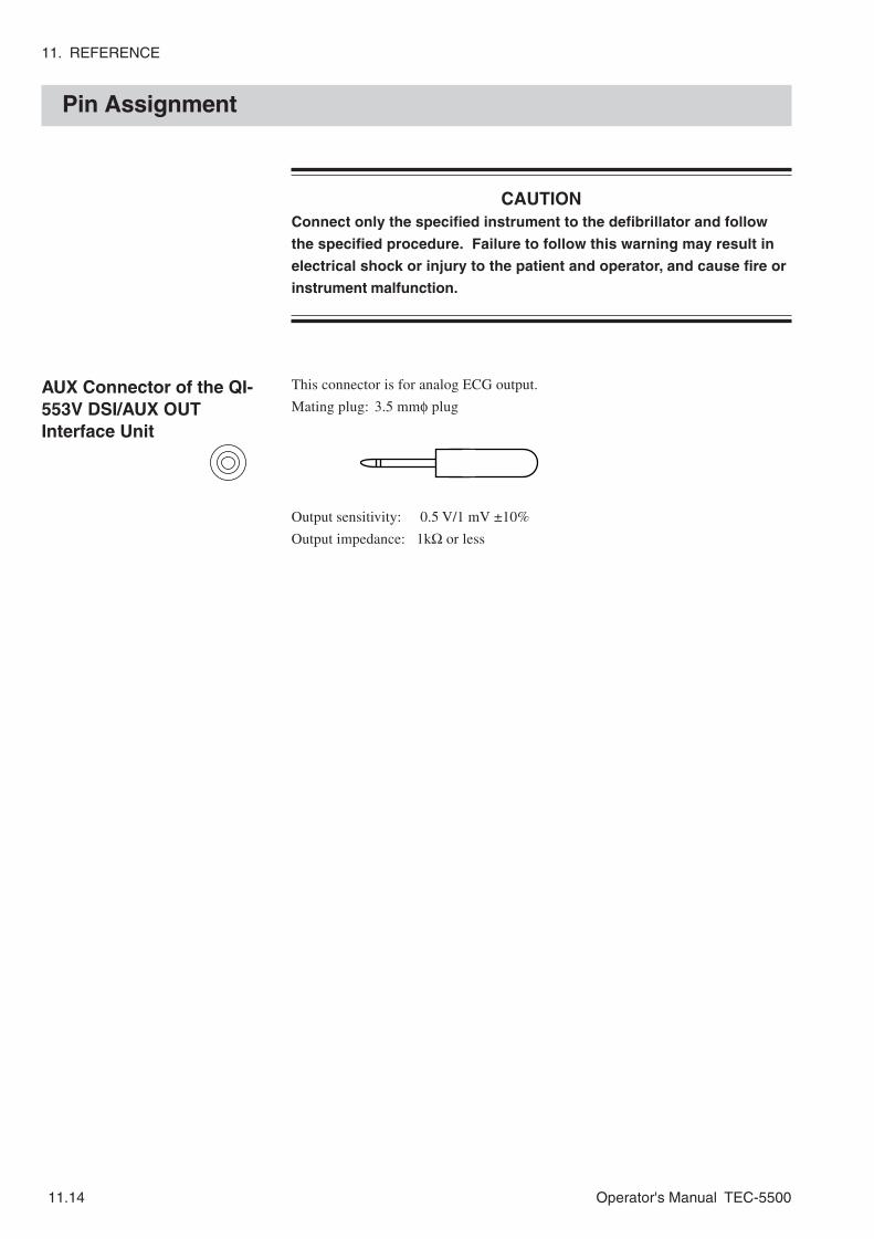
11. REFERENCE
11.14 Operator's Manual TEC-5500
Pin Assignment
AUX Connector of the QI-553V DSI/AUX OUTInterface Unit
CAUTIONConnect only the specified instrument to the defibrillator and follow
the specified procedure. Failure to follow this warning may result in
electrical shock or injury to the patient and operator, and cause fire or
instrument malfunction.
This connector is for analog ECG output.
Mating plug: 3.5 mmφ plug
Output sensitivity: 0.5 V/1 mV ±10%
Output impedance: 1kΩ or less

11. REFERENCE
Operator's Manual TEC-5500 11.15
General Requirements for Connecting Medical Electrical System
When more than one electrical instrument is used, there may be electrical potential
difference between the instruments. Potential difference between instruments may
cause current to flow to the patient connected to the instruments, resulting in
electrical shock (micro shock). Therefore, electrical instruments must be
appropriately installed as specified in IEC 60601-1-1.
The following is an extract from IEC 60601-1-1 “Medical electrical equipment Part
1: General requirements for safety”. For details, refer to IEC 60601-1-1 and
consult with a biomedical engineer.
Examples of combinations of MEDICAL ELECTRICAL EQUIPMENT and
non-medical electrical equipment
IEC 60601/B = IEC 60601-1 EQUIPMENT of TYPE B with PATIENT connection
IEC 60601/F = IEC 60601-1 EQUIPMENT of TYPE BF or TYPE CF (or TYPE B
without PATIENT connection)
IEC 60601/X = IEC 60601-1 EQUIPMENT of TYPE B or TYPE BF or TYPE CF
IEC XXXXX = Equipment complying with e.g. IEC 348, IEC 950 etc.
P: additional protective earth
Q: additional separating transformer
R: floating power supply
S: separation
Situation No. Equipment A Equipment B Solution
1 IEC 60601/X OK
1a IEC XXXXX
OK, if ENCLOSURE LEAKAGE CURRENT is less than 0.5 mA. If the ENCLOSURE LEAKAGE CURRENT is more than 0.5 mA: Solution Q (separating transformers).
2a IEC 60601/X IEC 60601/B OK
2b IEC 60601/F IEC XXXXX for B any one of P, Q, R
2c IEC 60601/B IEC XXXXX for A solution P for B any one of P, Q, R
3a IEC 60601/X IEC 60601/B OK
3b IEC 60601/F IEC XXXXX OK
3c IEC 60601/B IEC XXXXX for A solution P
4 see 3a, 3b, 3c
5a IEC 60601/X IEC 60601/B for A solution P or S (groundloop possible)
5b IEC 60601/X IEC XXXXX for A solution P or S (groundloop possible)
6a IEC 60601/X IEC 60601/X OK (with S)
6b IEC 60601/X IEC XXXXX OK (with S)

11. REFERENCE
11.16 Operator's Manual TEC-5500
Legend:
(V) = Potential difference between different localities.
> < = SEPARATION DEVICE.
PE = Protective earth.
1
2
3
4
5
6
Situation No.PATIENT
ENVIRONMENTMedically-used
roomNon-medically used
room
A
PE
A B
PE PE
A BPE PE
A BPE
PE
A BPE
PE(V)
A BPE
PE
(V)