technical and operational guidance (techop) techop odp...
TRANSCRIPT
TECHOP
TECHNICAL AND OPERATIONAL GUIDANCE (TECHOP)
TECHOP_ODP_08_(O) (ANNUAL DP TRIALS AND GAP ANALYSIS)
SEPTEMBER 2014
TECHOP_ODP_08_(O)_(ANNUAL_DP_TRIALS_AND_GAP_ANALYSIS_Ver2_09201430 1
TECHOP
CONTENTS
SECTION PAGE 1 INTRODUCTION - TECHOP (TECHNICAL AND OPERATION GUIDANCE) ........................ 4 1.1 PREAMBLE .............................................................................................................................................................. 4 1.2 TECHOP_ODP......................................................................................................................................................... 4 1.3 TECHOP_GEN......................................................................................................................................................... 4 1.4 MTS DP GUIDANCE REVISION METHODOLOGY ................................................................................................. 5 2 SCOPE AND IMPACT OF THIS TECHOP ............................................................................. 6 2.1 SCOPE ..................................................................................................................................................................... 6 2.2 IMPACT .................................................................................................................................................................... 6 2.3 OWNERSHIP OF THE TRIALS PROGRAM ............................................................................................................ 6 2.4 METHODOLOGY ..................................................................................................................................................... 7 2.5 REDUNDANCY AND RELIABILITY ......................................................................................................................... 7 2.6 ANNUAL TRIALS ADDRESSING CAM AND TAM ................................................................................................... 8 3 CREATING THE ANNUAL DP TRIALS PROGRAM ............................................................. 9 3.1 INFORMATION REQUIRED TO COMPLETE THE ANNUAL DP TRIALS PROGRAM ........................................... 9 3.2 REVIEW OF FMEA .................................................................................................................................................. 9 3.3 CONDITIONS TO BE DEFINED .............................................................................................................................. 9 3.4 GUIDELINES FOR ESTABLISHING SAFE AND VALID TEST CONDITIONS ...................................................... 10 3.5 PROVING THE INTEGRITY OF THE REDUNDANCY CONCEPT ........................................................................ 11 3.6 THE FAIL SAFE CONDITION OF THRUSTERS ................................................................................................... 11 3.7 CONTROL MODE TESTS ..................................................................................................................................... 12 3.8 TESTING RECOMMENDED BY IMCA M191 ........................................................................................................ 12 3.9 MODIFICATIONS ................................................................................................................................................... 12 4 FORMAT OF THE ANNUAL DP TRIALS PROGRAM – IMCA M191 .................................. 13 4.1 OVERALL FORMAT ............................................................................................................................................... 13 4.2 PART 1 - INTRODUCTION .................................................................................................................................... 13 4.3 PART 2 - TESTING ................................................................................................................................................ 13 4.4 PART 3 - VERIFICATION ...................................................................................................................................... 14 4.5 PART 4 - FINDINGS REGISTER ........................................................................................................................... 14 4.6 PART 5 - SIGNATURE SHEET .............................................................................................................................. 14 5 CONTENTS OF THE TEST PROGRAM – M191 ................................................................. 15 5.1 TESTING DP CLASS 2 & DP CLASS 3 ................................................................................................................. 15 5.2 PERFORMANCE TESTS ....................................................................................................................................... 15 5.3 SWITCHED OR STANDBY REDUNDANCY TESTS ............................................................................................. 16 5.4 PROTECTIVE FUNCTION TESTS ........................................................................................................................ 16 5.5 DP CLASS 3 GROUP REDUNDANCY BASED ON PHYSICAL SEPARATION .................................................... 17 5.6 CONTROL MODES ................................................................................................................................................ 17
2 TECHOP_ODP_08_(O)_(ANNUAL_DP_TRIALS_AND_GAP_ANALYSIS_Ver2_09201430

TECHOP
5.7 FAIL SAFE CONDITION OF THE THRUSTERS ................................................................................................... 17 6 CONTENTS OF THE VERIFICATION PROGRAM - M191 .................................................. 18 6.1 VERIFICATION PROCEDURE .............................................................................................................................. 18 6.2 REVIEW OF FMEA AND PROVING TRIALS ......................................................................................................... 19 6.3 MAINTENANCE FOR RELIABILITY ...................................................................................................................... 19 6.4 FORMAT OF TEST SHEETS FOR VERIFICATION- M191 ................................................................................... 19 7 GENERATING FINDINGS FROM TEST RESULTS ............................................................. 20 7.1 FINDING CATEGORIES IMCA M190 .................................................................................................................... 20 7.2 FINDINGS CATEGORIES IMCA - M191 ................................................................................................................ 20 7.3 DETAILED GUIDANCE ON FINDINGS FOR IMCA M191 ..................................................................................... 21
APPENDIX A TEST SHEET FOR USE AT ANNUAL TRIALS - M191.......................................... 23
APPENDIX B TEST SHEET FOR REVIEW OF PLANNED MAINTENANCE ............................... 25
APPENDIX C EXAMPLE FINDINGS REGISTER FOR M191 ....................................................... 27
APPENDIX D ANNUAL TRIALS GAP ANALYSIS ....................................................................... 29 D.1 GUIDE TO COMPLETING THE GAP ANALYSIS TABLE ...................................................................................... 30 D.2 REVIEW OF PREAMBLE ....................................................................................................................................... 31 D.3 REVIEW OF CONTENT ......................................................................................................................................... 32
TECHOP_ODP_08_(O)_(ANNUAL_DP_TRIALS_AND_GAP_ANALYSIS_Ver2_09201430 3
TECHOP
1 INTRODUCTION - TECHOP (TECHNICAL AND OPERATION GUIDANCE)
1.1 PREAMBLE 1.1.1 The guidance documents on DP (Design and Operations) were published by the MTS DP
Technical Committee in 2011 and 2010, Subsequent engagement has occurred with:
• Classification Societies (DNV, ABS). • United States Coast Guard (USCG). • Marine Safety Forum (MSF).
1.1.2 Feedback has also been received through the comments section provided in the MTS DP Technical Committee Web Site.
1.1.3 It became apparent that a mechanism needed to be developed and implemented to address the following in a pragmatic manner.
• Feedback provided by the various stakeholders. • Additional information and guidance that the MTS DP Technical Committee wished
to provide. • Means to facilitate revisions to the documents and communication of the same to the
various stakeholders.
1.1.4 The use of Technical and Operations Guidance Notes (TECHOP) was deemed to be a suitable vehicle to address the above. These TECHOP Notes will be in two categories:
• TECHOP_ODP. • TECHOP_GEN.
1.2 TECHOP_ODP 1.2.1 Technical guidance notes provided to address guidance contained within the Operations,
Design or People (Future development planned by the MTS DP Technical Committee) documents will be contained within this category.
1.2.2 The TECHOP will be identified by the following:
TECHOP_ODP_SNO_CATEGORY (DESIGN (D) OPERATIONS (O) PEOPLE (P).
• EG 1 TECHOP_ODP_01_(O)_(HIGH LEVEL PHILOSOPHY). • EG 2 TECHOP_ODP_02_(D)_(BLACKOUT RECOVERY).
1.3 TECHOP_GEN 1.3.1 MTS DP TECHNICAL COMMITTEE intends to publish topical white papers. These topical
white papers will be identified by the following:
TECHOP_GEN_SNO_DESCRIPTION.
• EG 1 TECHOP_GEN_01-WHITE PAPER ON DP INCIDENTS. • EG 2 TECHOP_GEN_02-WHITE PAPER ON SHORT CIRCUIT TESTING.
4 TECHOP_ODP_08_(O)_(ANNUAL_DP_TRIALS_AND_GAP_ANALYSIS_Ver2_09201430

TECHOP
1.4 MTS DP GUIDANCE REVISION METHODOLOGY 1.4.1 TECHOP as described above will be published as appropriate. These TECHOP will be
written in a manner that will facilitate them to be used as standalone documents.
1.4.2 Subsequent revisions of the MTS Guidance documents will review the published TECHOPs and incorporate as appropriate.
1.4.3 Communications with stakeholders will be established as appropriate to ensure that they are notified of intended revisions. Stakeholders will be provided with the opportunity to participate in the review process and invited to be part of the review team as appropriate.
TECHOP_ODP_08_(O)_(ANNUAL_DP_TRIALS_AND_GAP_ANALYSIS_Ver2_09201430 5

TECHOP
2 SCOPE AND IMPACT OF THIS TECHOP 2.1 SCOPE 2.1.1 TECHOP_ODP_08_(O)_(ANNUAL DP TRIALS AND GAP ANALYSIS). This TECHOP
describes how to create an Annual DP Trials program that complies with the requirements of IMCA M190 & M191 using information obtained from the vessel’s DP failure modes and effects analysis and associated proving trials program. This document focuses primarily on how to create the trials program but also gives practical advice on how it should be used (where such detail is not included in IMCA M190 & M191).
2.1.2 The MTS guidance documents published have supplemented the guidance documents provided by IMCA with a focus on industrial mission requirements and introduced the concepts of CAM and TAM.
2.1.1 Comprehensive guidance on the format of an Annual DP Trials report is given in IMCA M190. The same degree of information is not provided in IMCA M191 Therefore; much of the guidance provided in this TECHOP refers to IMCA M191 and is identified as such.
2.1.2 Guidance is also provided in the form of a Gap Analysis Template in Appendix A which allows stakeholders to judge to what extent any given Annual DP trials program complies with the guidance provided by IMCA and MTS.
2.1.3 This TECHOP is supplementary to and should be read in conjunction with:
• IMCA M190, ‘Guidance for Developing and Conducting Annual DP Trials Programmes for DP Vessels, June 2011.
• IMCA M191, ‘Guidelines for Annual DP Trials for DP Mobile Offshore Drilling Units’. February 2008.
• MTS DP Vessel Design Philosophy Guidelines • MTS DP Operations Guidance
2.1.4 Nothing in this Techop is intended to override requirements imposed by the classification societies to maintain DP equipment class notation. Where suggestions for test intervals exceeding one year are made in this Techop it is to be understood that this only applies when there is no conflict with classification society or other statutory requirements.
2.1.5 This Techop may be used to supplement class annual surveys.
2.2 IMPACT 2.2.1 This TECHOP applies primarily to vessels of IMO DP Equipment Classes 2 & 3. Although
there are no requirements for DP Equipment Class 1 vessels to have an FMEA or conduct Annual DP Trials some owners elect to do this for their own edification. Although separate IMCA guidance exists for MODUs and other DP vessels the only practical differences are that MODUs can carry out their annual trials as part of a continuous program. Other DP vessel types perform annual trials on dates determined by the anniversary of their DP FMEA proving trials.
2.3 OWNERSHIP OF THE TRIALS PROGRAM 2.3.1 Although the trials program may be developed for the vessel owner, it is essential that the
program itself is owned by the vessel and form part of its safety management systems and is subject to the vessel owner’s procedures for control and amendment of such documents.
6 TECHOP_ODP_08_(O)_(ANNUAL_DP_TRIALS_AND_GAP_ANALYSIS_Ver2_09201430

TECHOP
2.4 METHODOLOGY 2.4.1 There are three important elements in any fault tolerant system based on redundancy.
1. Performance. 2. Protection. 3. Detection.
2.4.2 Trials carried out on redundant systems attempt to prove that these elements are present where required.
2.4.3 Performance: Redundant elements must be present in the required number and capacity to support the redundancy concept. Their performance must be equivalent or the overall environmental envelope is determined by the capacity of the less capable unit. Performance may be defined by a number of criteria such as full load capability, load acceptance and rejection, endurance, repeatability, resolution and accuracy. The DP system FMEA should identify where the redundancy concept depends on these functions and the annual trials program should include tests to prove equipment performance.
2.4.4 Protection: In virtually all redundant systems there are common points connecting redundant parts of these systems. These common points provide paths by which faults may propagate from one redundant system to another. There must be a comprehensive range of protective functions designed to identify and isolate the faults before the redundant system is affected. Automatic isolation is preferred where the time constraints preclude a credible operator response. Protective functions are also used to prevent control systems acting on erroneous information or data that is obviously out of range. In addition, they are also used to identify equipment that is not responding correctly and shut it down before it can affect the operation of the system. The FMEA should identify these protective functions and the annual trials should demonstrate their effectiveness where it is practical to do so.
2.4.5 Detection: The redundancy concept may be compromised if redundant elements are not available on demand. Alarms are used to indicate equipment failure. These may be used to indicate to the DPO that the DP system is no longer fully fault tolerant or that action is required to prevent failure effects escalating. Alarms may also be used to indicate that equipment is not functioning as expected or that some part of the DP system is not configured correctly. Alarms have an important role to play in monitoring the readiness of standby redundancy. The FMEA and FMEA proving trials should identify any alarm on which the redundancy concept depends and these should be proven in the Annual DP Trials. Periodic inspection and checklists may be accepted in lieu of certain alarms, particularly, if it is not practical to have an alarm.
2.5 REDUNDANCY AND RELIABILITY 2.5.1 IMO ‘Guidelines for Vessels with Dynamic Positioning Systems’, MSC645, requires that
DP vessels have a sufficiently reliable station keeping capability. For equipment class 2 this is to be achieved by redundancy of all active components. For equipment class 3 there should be redundancy of all components and physical separation of the components.
2.5.2 The requirement for a sufficiently reliable station keeping capability is only likely to be met if the equipment, functions and features on which the redundancy concept depends are maintained and each redundant element is sufficiently reliable in its own right.
TECHOP_ODP_08_(O)_(ANNUAL_DP_TRIALS_AND_GAP_ANALYSIS_Ver2_09201430 7
TECHOP
2.6 ANNUAL TRIALS ADDRESSING CAM AND TAM 2.6.1 Nothing in this Techop is intended to contradict the requirements to comply with the
applicable classification society or flag state rules & requirements.
2.6.2 Nothing in this Techop points to or alludes to requiring short circuit testing on an annual basis or at any other interval.
2.6.3 One of the stated purposes of annual trials in IMO MSC645 is to test all important systems and component to document the ability of the DP system to maintain position after single failures. To demonstrate this ability, each important system needs to have the necessary performance characteristics required by the vessel’s post failure capability. Each essential protective function needs to be able to prevent single failures propagating from one redundant group to another. Attributes of the redundancy concept that have the potential to be compromised (example voltage dip ride through) should be tested annually by appropriate test methodologies.
2.6.4 Frequency of testing: This Techop acknowledges the variability in comprehension and application of the requirements of annual trials which results in different strategies that may not achieve the intent of annual trials namely demonstrating performance, protection and detection.
2.6.5 Annual trials (at least 12 months, ±3 months) should test those functions that validate and verify the functionality of performance, protection and detection for CAM configurations.
2.6.6 CAM configurations that permit operating the power plant as a single power system (closed busties) will have significantly higher test requirements to be conducted compared with CAM configurations with open busties.
2.6.7 Alternate strategies for testing important systems which are only relied upon in TAM configurations may be considered. The basis for alternate strategies should be clearly documented and and supported by appropriate HEMP processes. MTS Design Philosophy Guidelines encourages the development of configurations for TAM that are fully fault tolerant but it accepted that this is a risk based configuration.
2.6.8 The basis of any Annual DP Trials program should be a trials document which is designed to test the vessel’s DP redundancy concept and configurations analysed in the class approved DP FMEA. Adaptations to accommodate testing for CAM and TAM alternative strategies should be part of that base document and clearly explained within it.
8 TECHOP_ODP_08_(O)_(ANNUAL_DP_TRIALS_AND_GAP_ANALYSIS_Ver2_09201430
TECHOP
3 CREATING THE ANNUAL DP TRIALS PROGRAM 3.1 INFORMATION REQUIRED TO COMPLETE THE ANNUAL DP TRIALS
PROGRAM 3.1.1 The following information is required to create the Annual DP Trials program:
1. An up-to-date DP FMEA. 2. The FMEA Proving Trials Programme. 3. IMCA M190, Guidance For Annual DP Trials Programmes For DP Vessels 4. IMCA M191, ‘Guidelines For Annual DP Trials for DP Mobile Offshore Drilling Units 5. Details any hardware and software changes since the FMEA was last revised. 6. Procedures for developing the Annual DP Trials programme - (this document).
3.2 REVIEW OF FMEA 3.2.1 The FMEA should be reviewed to fully understand the redundancy concept. The following
should be identified:
1. The worst case failure design Intent. 2. The operating configurations. 3. The vessel’s DP capability in the intact and post WCF conditions. 4. The redundant groups to which DP related equipment belongs. 5. All common points connecting redundant elements. 6. All protective functions upon which the redundancy concept depends. 7. All alarms required to indicate potential hidden failure or loss of redundancy. 8. All equipment and systems which may suffer a significant deterioration in capacity /
performance. 9. All equipment and systems which may suffer a significant deterioration in accuracy. 10. The fail safe condition of thrusters. 11. All systems recommended for testing by IMCA M190 & M191.
3.3 CONDITIONS TO BE DEFINED 3.3.1 The Worst Case Failure Design Intent: The Worst Case Failure Design Intent (WCFDI)
establishes the maximum amount of power and propulsion machinery that should be lost following the worst case failure. The WCFDI should be derived from the FMEA and stated in the introduction to the Annual DP Trials program.
3.3.2 The operating configurations: The operating configuration should be as described in the FMEA and DP Bridge and engine room checklists. The configurations will be used during testing. The program will identify any tests where the outcome is configuration dependent and these tests will be carried out in all applicable configurations. Test sheets should describe the required configurations.
3.3.3 The vessel’s DP capability: This should be derived from DP capability plots and should be used to confirm that the trials are being carried out within the vessel’s intact and post failure environmental envelopes.
TECHOP_ODP_08_(O)_(ANNUAL_DP_TRIALS_AND_GAP_ANALYSIS_Ver2_09201430 9
TECHOP
3.4 GUIDELINES FOR ESTABLISHING SAFE AND VALID TEST CONDITIONS 3.4.1 The introduction to the trials program will contain guidance on how to ensure tests results
are valid. The following points may be used in conjunction with any others considered appropriate for the particular application.
1. Pre-requisites: During the trials, all equipment necessary to ensure a valid test result should be operational. In particular, all propulsion units and their controls, both manual and automatic, all power generation equipment, all computer systems and all position reference systems must be fully functional, including their alarms, standby units, battery backups, shutdowns, trips, etc.
2. Deviation from trials pre-requisites: In cases where the trials prerequisites cannot be met it may still be possible to carry out some or all of the parts of a test. In such circumstances, any deviation from the required conditions or configuration should be noted in the comments section of the test sheet so that the reasons for continuing the test can be understood.
3. All trials will be conducted with the approval of the Master and with full regard to the safe navigation of the vessel.
4. A trials coordinator should be appointed to facilitate efficient execution of the trials. The trials coordinator should not be the independent witness as described in IMCA M190.
5. The trials coordinator should be satisfied, by whatever means necessary, that a test can be conducted safely and any test that cannot be conducted safely will be cancelled. A suitable and sufficient risk assessment should also be carried out by the vessel’s staff for any tests where there is a risk of equipment damage even if that test can be conducted safely. If it is determined that the risks are unacceptably high then alternative means of obtaining the same information should be developed.
6. During failure tests, the system should not be reinstated until the DP operators, ECR staff and witnesses are satisfied they understand the full effects of the failure and that all the information or indicators that show what has occurred have been noted.
7. The next test in a sequence of tests should only be carried out when the DP system has been reset and has stabilised unless the next step in the test program requires otherwise.
8. A test result should only be accepted as valid if all those involved in its execution are satisfied that it was performed and recorded correctly.
9. Suitable communications should be arranged between the test location and other locations at which alarms and indications are being recorded.
10. Care should be taken to return the DP system to its fully intact condition after testing is complete.
10 TECHOP_ODP_08_(O)_(ANNUAL_DP_TRIALS_AND_GAP_ANALYSIS_Ver2_09201430

TECHOP
3.5 PROVING THE INTEGRITY OF THE REDUNDANCY CONCEPT 3.5.1 Redundant groups to which DP related equipment belongs: Redundant groups should be
identified to create the group redundancy test. This will simulate total failure of an entire redundant group to simulate worst case failures. Satisfactory positioning will be demonstrated using each redundant group.
3.5.2 Common points connecting redundant elements: A comprehensive list of the common points in the redundancy concept will be derived from the review of the FMEA and used to cross check the list of protective functions to be tested.
3.5.3 Protective functions upon which the redundancy concept depends: All protective functions upon which the redundancy concept depends will be identified from the FMEA. The annual trials program will ensure that these functions are proven by testing or by reference to maintenance records as appropriate.
3.5.4 Alarms required to indicate potential hidden failures, loss of redundancy and configuration errors. In general, testing of alarms required to indicate potential configuration errors or hidden failures will be included the list of items to be verified by a review of planned maintenance.
3.5.5 Equipment and systems which may suffer a significant deterioration in capacity / Performance: Testing the performance of engines and thrusters would normally be included in items to be carried out at Annual DP Trials opportunities but other systems may be included in planned maintenance such as cooling systems.
3.5.6 Equipment and systems which may suffer a significant deterioration in accuracy: Sensors and reference systems are in continual operation on a DP vessel and deterioration is likely to be noted in service. Testing the performance of sensors and reference systems may be combined with the group redundancy test as a means of demonstrating the vessel’s ability to maintain position in the degraded condition.
3.6 THE FAIL SAFE CONDITION OF THRUSTERS 3.6.1 IMO, IMCA and DNV rules and guidelines require thrusters to fail safe. Thrusters should
not fail to uncontrolled thrust magnitude or direction. The fail safe condition is generally accepted to be fail ‘as set’, ‘to zero thrust’, or ‘propeller stop’. Uncontrolled changes in thruster direction are acceptable if at the same time the thrust is set to zero. These tests should include failure of the local pitch and azimuth command and feedback loops. The test should include demonstration of the ‘prediction errors’ intended to alert the DPO to the fact that the thruster is malfunctioning.
3.6.2 For vessels with Controllable Pitch Propellers tests to prove the fail safe condition should be carried out annually due the high probability that these types of thrusters fail to full thrust. In particular, deterioration of the hydraulic pitch setting components can have this effect. Means to reduce the risk of errors and fatigue failures associated with frequent wire-break tests should be implemented (example knife contacts or switches).
3.6.3 For vessels with Fixed Pitch Propellers driven by variable speed drives, tests to prove the fail safe condition can be carried out at the DP FMEA proving trials and then as a rolling program covering all thrusters in five years due the low probability that these types of thruster fail to full thrust in response to control loop failure. Means to reduce the risk of errors and fatigue failures associated with frequent wire-break tests should be implemented as described above.
3.6.4 Tests should also be carried out after any significant modification.
TECHOP_ODP_08_(O)_(ANNUAL_DP_TRIALS_AND_GAP_ANALYSIS_Ver2_09201430 11

TECHOP
3.7 CONTROL MODE TESTS 3.7.1 The annual trials may also be used to test control modes not normally exercised when the
vessel is carrying out its industrial mission including DP joystick, manual control levers and independent joystick.
3.8 TESTING RECOMMENDED BY IMCA M191 3.8.1 IMCA M191 recommends the following ‘essential’ tests:
1. All prime movers to full power for long enough for temperatures to stabilise or for a minimum of 15 minutes with tests to be allowed in pairs or groups.
2. All thrusters and propellers to full power long enough for temperatures to stabilise or not on DP thruster azimuth rates and ramp rates to be verified.
3. Demonstration of failures leading to the worst case failure effect. 4. Demonstration of open and closed bus power management systems for power limit,
increase of online power capacity and power restoration (blackout recovery). 5. Network failures for DP and integrated control systems.
3.9 MODIFICATIONS 3.9.1 If there have been hardware or software changes since the last revision of the FMEA then
the analysis should be updated either by another revision or by a supplement to fully understand the implication for the redundancy concept and trials program. The functionality provided by revised software should be reviewed for its impact on the redundancy concept and on expected results. A supplementary trials program designed to prove the effect of the modifications on the redundancy concept should be carried out at the time of the modification. The annual trials program should be updated to reflect the changes before the next test opportunity.
12 TECHOP_ODP_08_(O)_(ANNUAL_DP_TRIALS_AND_GAP_ANALYSIS_Ver2_09201430

TECHOP
4 FORMAT OF THE ANNUAL DP TRIALS PROGRAM – IMCA M191 4.1 OVERALL FORMAT 4.1.1 Unlike IMCA M190, no example report template is provided in IMCA M191. The following
format is suggested for a continuous annuals trials report based on the guidance in IMCA M191.
1. Part 1 - Introduction. 2. Part 2 - Items to be verified by testing. 3. Part 3 - Items to be verified by reference to maintenance records. 4. Part 4 - Findings log. 5. Part 5 - Signature sheet.
4.2 PART 1 - INTRODUCTION 4.2.1 Part 1 should include a brief overview of the redundancy concept and identify those critical
items on which the redundancy concept depends.
1. General introduction. 2. Vessel particulars. 3. Overview of redundancy concept.
• Worst case failure • Common points • Protection devices • Alarms
4. Test matrix with expected test durations and log of completion dates. 5. Guidelines for establishing safe and valid test conditions. 6. Guidance on generating recommendations from test results.
4.3 PART 2 - TESTING 4.3.1 Part 2 should contain the test sheets for use on a continuous basis. The test sheets have
the following parts as per the examples in Appendix A:
1. Test number. 2. Cross reference to the FMEA. 3. Configuration for test. 4. Document reference. 5. Purpose. 6. Method. 7. Expected results - locally and for DP. 8. Actual results. 9. Comments. 10. Signature of person carrying out the test. 11. Signature of vessel master / OIM witnessing the test – M191. 12. Signature of independent witness – IMCA M190.
4.3.2 The FMEA proving trials may be used as a source of information for creating tests.
TECHOP_ODP_08_(O)_(ANNUAL_DP_TRIALS_AND_GAP_ANALYSIS_Ver2_09201430 13

TECHOP
4.3.3 Tests which may carry a risk of loss of position should not be performed when the vessel is connected to the well. These tests will be carried out by vessel staff when the opportunity presents itself.
4.3.4 The trials program should be cross referenced to the FMEA: The ‘Purpose’ section of the FMEA test sheets should explain the reason for the test and what feature of the redundancy concept is being proven. Each test sheet should cross reference a particular statement or conclusion of the FMEA to which the test refers.
4.4 PART 3 - VERIFICATION 4.4.1 Part 3 contains test sheets which may be signed off by a review of planned maintenance
records prior to submission of the trials program results for the annual verification. Alternatively, should there be a requirement to perform the Annual DP Trials as a single test program, say after drydocking, the tests sheets can be used in the traditional manner.
4.4.2 Planned maintenance which may carry a risk of loss of position should not be performed when the vessel is connected to the well or otherwise restricted in its ability to manoeuvre. Such maintenance activities should be carried out by vessel staff when the opportunity presents itself.
4.4.3 Frequency of testing: Although it is expected that all tests in Part 2 will be completed annually and all items in Part 3 will be verified annually by reference to planned maintenance records, the frequency with which the planned maintenance activities are carried out may be determined by manufacturers’ recommendations or class requirements. Items which may fall into this category include such things as electrical protection, alarms and shutdowns for E0 or ACCU notation. It is expected that standby generators and duty standby pumps will be proven several times in the course of a year. The justification for the selected test interval should be recorded on the test sheet. The purpose of the annual verification is to confirm the maintenance is in-date.
4.5 PART 4 - FINDINGS REGISTER 4.5.1 A findings register is to be provided for recording unexpected results and their associated
category. A new findings register should be started for each new annual trials period but outstanding findings may be carried over. The vessel owner’s procedures for addressing recommendations in each category should be applied. The findings register should be in the form of the table in Appendix C. The findings register will be reviewed at the annual verification. The findings register should have the following entries:
1. ID numbers run sequentially throughout the trials period. 2. Test number - cross referenced to the test. 3. Finding - details of the unexpected results or other finding. 4. Date raised - usually the date of the test. 5. Category - Which level applies to the failure effect or observation A, B or C. 6. Action - the action taken to close out the finding. 7. Date closed. 8. Remarks - additional useful information.
4.6 PART 5 - SIGNATURE SHEET 4.6.1 The signature sheet will provide space for the Master / OIM to sign off the completed trials
program prior to submission for the annual verification. Provision will also be made for the person responsible for the annual verification to confirm that the annual trials record meets company requirements.
14 TECHOP_ODP_08_(O)_(ANNUAL_DP_TRIALS_AND_GAP_ANALYSIS_Ver2_09201430

TECHOP
5 CONTENTS OF THE TEST PROGRAM – M191 5.1 TESTING DP CLASS 2 & DP CLASS 3 5.1.1 Section 4.7.5 of IMCA M190 provides guidance on the contents of the trials program. For
IMCA M191 the test program would normally contain those items that could not easily be proven by planned maintenance activities or which require special focus. The following tests would typically be carried out as part of the testing process on a continual basis throughout the year as opportunities for testing become available.
1. Generator full power test. 2. Thruster full power test. 3. Group redundancy tests for each redundant group. 4. Switched or standby redundancy tests. 5. Protective function test for each operational configuration. 6. DP Class 3 group redundancy based on physical separation. 7. Control modes. 8. Fail safe condition of the thrusters.
5.1.2 The tests listed below contain a number of options for combining tests which may be employed to extend the scope and improve the efficiency of testing. Review of the FMEA and operational constraints may determine whether it is practical to do so.
5.2 PERFORMANCE TESTS 5.2.1 Generator full power tests 5.2.2 Purpose: This test will prove the full load capability and load acceptance of the generators.
5.2.3 Method: Generator will be loaded to 100% for 15 minutes or until temperatures stabilise whichever is shorter. Tests will be carried out individually or in groups using thruster bias or whatever means available. At the end of test period the load acceptance will be proven by stopping generators in parallel to create the required load step.
5.2.4 Thruster full power tests 5.2.5 Purpose: This test will prove the full power capability of the thrusters.
5.2.6 Method: Thrusters will be loaded to 100% for 15 minutes in pairs or groups. The test may be carried out in manual mode or in DP using thruster bias. Ramp times and rotation times should be recorded.
5.2.7 Network throughput test 5.2.8 Purpose: To confirm the DP and Vessel control networks still have the expected capacity.
5.2.9 Method: this test is typically carried out by the original equipment vendor using their own test gear. For MODUs this may require alignment with a scheduled vendor maintenance visit to the rig. For other vessels it may be necessary for a vendors representative to attend for trials as may be the case following dry-docking etc. Alternatively, the vendor may be able to train crew members to carry out this task.
5.2.10 Group redundancy tests 5.2.11 Purpose: This test will prove the vessel can maintain position and heading with each of the
redundant groups of propulsion machinery. The vessel must be able to hold position and heading after the loss of each redundant group identified by the FMEA. Loss of one group is likely to represent the worst case failure.
TECHOP_ODP_08_(O)_(ANNUAL_DP_TRIALS_AND_GAP_ANALYSIS_Ver2_09201430 15

TECHOP
5.2.12 Method: For a typical diesel electric DP Class 2 vessel with a two-way split in the redundancy concept this test will involve shutting down one entire side of the power generation and distribution system and demonstrating that the vessel can hold position and heading with the machinery that remains online. The test sheet will include a checklist of DP essential equipment that should be operational in each redundant group. The following options can be included with the group redundancy test.
1. Option: This test may be combined with failure of the UPS distributions associated with redundant group that has been shut down such that redundant vessel control. DP control and power is failed at the same time. Alternatively, failure of UPS distribution may be a separate test.
2. Option: This test may be combined with the thruster full power test using all the thrusters in the redundant group under test. This will confirm the surviving marine auxiliary system can support the thrusters at high load.
3. Option: This test can be combined with DP control system performance tests (box and circle tests) to demonstrate the vessel can manoeuvre accurately with the surviving position references sensors and control systems. Alternatively this test can be conducted with the UPS distribution failure test.
4. Option: The switched or standby redundancy test may be combined with this test by ensuring that the switched (transferable) consumer is fed from the redundant group to be failed prior to the test commencing. The test should confirm the effective transfer of the consumer or the start of a standby unit.
5.3 SWITCHED OR STANDBY REDUNDANCY TESTS 5.3.1 Purpose: This test is intended to prove the effectiveness of switched redundancy such as
transferable generators and thrusters with dual supplies but also auto changeovers for UPSs and other purposes if these are not tested for other reasons.
5.3.2 Method: Tests will be created to exercise the changeover function or dual supply. Tests to confirm alarms and monitoring of backup supplies for standby units may be part of the verification of planned maintenance work.
5.3.3 Option: The switched or standby redundancy test may be combined with the group redundancy test by ensuring that the switched (transferable) consumer is fed from the redundant group to be failed prior to the test commencing.
5.4 PROTECTIVE FUNCTION TESTS 5.4.1 PMS and generator Protection 5.4.2 Purpose: This test is intended prove the operation of all protective functions upon which
the redundancy concept depends (which are not proven as part of planned maintenance). The review of the FMEA will identify all protective functions which must operate effectively to isolate faults or prevent cascade failures. Tests are limited to protective functions depending on hardware. Protective functions entirely dependent on software are proven by other means. Tests should be carried out in all power plant configurations.
16 TECHOP_ODP_08_(O)_(ANNUAL_DP_TRIALS_AND_GAP_ANALYSIS_Ver2_09201430

TECHOP
5.4.3 Tests of protection functions will typically include:
1. Load dependent starting of standby generators. 2. Starting of standby generators in response to alarm on running generator. 3. Load shedding - drilling phase back. 4. Load shedding - thruster phase back. 5. Load shedding - preferential trips. 6. Blackout restart and recovery. 7. Specialised generator and bus bar protection. 8. Thruster emergency stops.
5.4.4 Method: Tests should be created to prove the effectiveness of the protective functions identified in the FMEA in as realistic a manner as possible.
5.4.5 Network storm tests 5.4.6 Purpose: To confirm that the protective functions in the DP and vessel control networks
remain effective. Industry experience confirms the need to maintain high confidence in network integrity.
5.4.7 Method: This test is typically carried out by the original equipment vendor using their own test gear. For MODUs this may require alignment with a scheduled vendor maintenance visit to the rig. For other vessels it may be necessary for a vendors representative to attend for trials as may be the case following dry-docking etc. Alternatively, the vendor may be able to train crew members to carry out this task.
5.5 DP CLASS 3 GROUP REDUNDANCY BASED ON PHYSICAL SEPARATION 5.5.1 Purpose: This test is similar to that used for the regular group redundancy tests. In this
case, the redundant groups are based on physical separation as well as technical failure. Tests will include demonstration of station keeping using the backup DP control system.
5.5.2 Method: Redundant groups will be based on physical separation. The test may require shutting down all equipment in one compartment at the same time and demonstrating station keeping ability.
5.6 CONTROL MODES 5.6.1 Purpose: To verify the smooth transfer and operation of control functions that are not
normally used while the vessel is connected to the well but which may be required in the event of an emergency.
5.6.2 Method: This test could be carried out during a transit or in-field move. The test would verify the correct operation of all means of control including DP joystick, independent joystick and manual levers.
5.7 FAIL SAFE CONDITION OF THE THRUSTERS 5.7.1 Purpose: To verify that failure of the local control loop does not result in uncontrolled
change in thrust magnitude or direction. See also Section 3.6 on when this test is required.
5.7.2 Method: Circuits for DP and local thruster control loops (command and feedback) will be interrupted.
TECHOP_ODP_08_(O)_(ANNUAL_DP_TRIALS_AND_GAP_ANALYSIS_Ver2_09201430 17

TECHOP
6 CONTENTS OF THE VERIFICATION PROGRAM - M191 6.1 VERIFICATION PROCEDURE 6.1.1 No verification process is required for IMCA M190. The only requirement is that trials be
witnessed by a competent person who is considered to be independent. The level of independence is a matter for the vessel owner. When choosing an independent witness the vessel owner may wish to consider what degree of independence is likely to satisfy prospective charterers.
6.1.2 For MODUs following IMCA M191, an annual verification is to be carried out by the vessel owner or his nominee to confirm that all tests in the Annual DP Trials program have been carried out. This verification should be carried out within three months of the end of the Annual DP Trials period. The vessel owner may choose to audit the progress of the trials program more frequently (say every six months) to ensure that adequate time remains to complete the work within the time available.
6.1.3 Test sheets are created for those items to be verified by planned maintenances in the M191. Should it be necessary, the test sheet can be used in the traditional way but the normal procedure would be for the vessel’s engineers to create an entry in the planned maintenance system for each test sheet using the test procedures and expected results on the test sheet. In M190 test sheets that contain tests that may be satisfied by review of planned maintenance are simple annotated to the effect.
6.1.4 Each planned maintenance job is cross referenced to the test sheet using the job number from the planned maintenance system. The person on-board responsible for the annual trials program will sign off each test sheet as ‘verified by review of planned maintenance records’. A printout of the complete planned maintenance job report can be attached to complete the record.
6.1.5 If at the annual M191 verification, all test sheets are signed off it is accepted that these tests have been completed. If it is noted that there are outstanding maintenance items then the owner’s procedures for dealing with such omissions should be applied.
6.1.6 For IMCA M190, a review of tests performed by planned maintenance is a part of the trials process carried out at an appropriate time in the program.
6.1.7 For IMCA M190, the independent witness should leave a letter with the master of the vessel summarising the trials findings. An example letter is provided in IMCA M190.
18 TECHOP_ODP_08_(O)_(ANNUAL_DP_TRIALS_AND_GAP_ANALYSIS_Ver2_09201430
TECHOP
6.2 REVIEW OF FMEA AND PROVING TRIALS 6.2.1 When creating the trials program, the review of the FMEA and proving trials program
should identify all those alarms, features and protective functions upon which the redundancy concept depends. Part of the process of creating the Annual DP Trials program is to identify those alarms, features and protective functions that can be verified by review of planned maintenance records and create test sheets to prove them.
6.2.2 Typical items which may be verified by review of planned maintenance include:
1. UPS battery endurance. 2. UPS alarms for ‘on batteries’, ‘on bypass’, main and backup supply. 3. Alarm for seawater cooling pressure. 4. Alarms for low fuel oil level. 5. Alarm for low air pressure. 6. Engine alarms and shutdowns such as lube oil pressure, high jacket water pressure. 7. Duty standby changeover of cooling water and other pumps. 8. Alarms for the failure of supplies to standby pumps. 9. Alarms for the failure of backup supplies.
6.3 MAINTENANCE FOR RELIABILITY 6.3.1 The primary purpose of the testing and verification process is to demonstrate that all
equipment and functions upon which the redundancy concept depends are operational. However, Annual DP Trials reports are also intended to prove that the vessel is well maintained and may include sections to demonstrate that important maintenance is up to date.
6.3.2 Typical review items may include:
1. Dates of sensor and reference system maintenance records. 2. Dates and subjects of latest sensor, reference and control system bulletins. 3. Dates and running hours since last major engine maintenance. 4. Dates of and results for last engine oil analysis. 5. Dates and running hours since last major thruster maintenance. 6. Dates of and results for last thruster oil analysis. 7. Records of regular fuel testing. 8. Main switchboard maintenance.
6.3.3 IMCA M191 makes no direct reference to what should be included and items may be added at the vessel owner’s discretion.
6.3.4 For IMCA M190 guidance on review and references to maintenance records etc. is given in the example Annual DP Trials Template in Appendix A of M190.
6.4 FORMAT OF TEST SHEETS FOR VERIFICATION- M191 6.4.1 Test sheets for verification by review of planned maintenance records will follow the same
format as those used for testing but they will be marked ‘for verification by review of planned maintenance records’ and have a cross reference to the planned maintenance job number as shown in Appendix B of this TECHOP.
TECHOP_ODP_08_(O)_(ANNUAL_DP_TRIALS_AND_GAP_ANALYSIS_Ver2_09201430 19

TECHOP
7 GENERATING FINDINGS FROM TEST RESULTS 7.1 FINDING CATEGORIES IMCA M190 7.1.1 When test results are not as expected it may indicate that the DP system is no longer fully
fault tolerant or not capable of its full post failure DP capability. Each finding should be assigned to one of three categories (A, B & C) according to its severity. Extensive guidance on categorisation of Annual DP Trials findings is provided in Section 5.12.2 of IMCA M190,
7.2 FINDINGS CATEGORIES IMCA - M191 7.2.1 Limited guidance on the assignment of categories for MODUs is provided in IMCA M191.
In practical terms the same technical guidance on assignment to Categories A, B and C can be applied to finding on MODUs. For vessels other than MODUs it has been traditional to assign categories based on the time considered appropriate for remedial action. An alternative strategy based on the impact on the redundancy concept is listed below. Further guidance on assigning findings categories is provided in Table 7-1 below.
• Category A The redundancy concept is no longer fully fault tolerant. Fault tolerance should be restored.
• Category B The redundancy concept is fully fault tolerant at reduced environmental limits. The vessel’s post failure DP capability should be redefined or full capability restored.
• Category C The redundancy concept is fully fault tolerant but an element of non-critical redundancy is unavailable.
20 TECHOP_ODP_08_(O)_(ANNUAL_DP_TRIALS_AND_GAP_ANALYSIS_Ver2_09201430
TECHOP
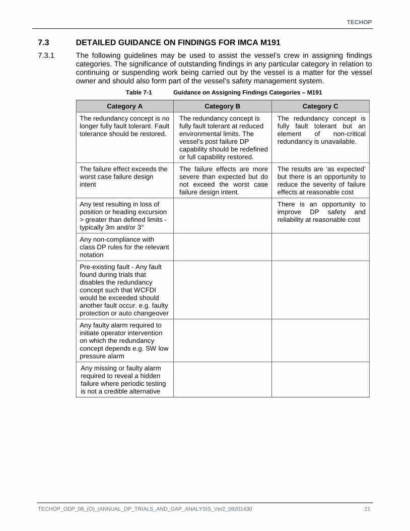
7.3 DETAILED GUIDANCE ON FINDINGS FOR IMCA M191 7.3.1 The following guidelines may be used to assist the vessel’s crew in assigning findings
categories. The significance of outstanding findings in any particular category in relation to continuing or suspending work being carried out by the vessel is a matter for the vessel owner and should also form part of the vessel’s safety management system.
Table 7-1 Guidance on Assigning Findings Categories – M191
Category A Category B Category C
The redundancy concept is no longer fully fault tolerant. Fault tolerance should be restored.
The redundancy concept is fully fault tolerant at reduced environmental limits. The vessel’s post failure DP capability should be redefined or full capability restored.
The redundancy concept is fully fault tolerant but an element of non-critical redundancy is unavailable.
The failure effect exceeds the worst case failure design intent
The failure effects are more severe than expected but do not exceed the worst case failure design intent.
The results are ‘as expected’ but there is an opportunity to reduce the severity of failure effects at reasonable cost
Any test resulting in loss of position or heading excursion > greater than defined limits - typically 3m and/or 3°
There is an opportunity to improve DP safety and reliability at reasonable cost
Any non-compliance with class DP rules for the relevant notation
Pre-existing fault - Any fault found during trials that disables the redundancy concept such that WCFDI would be exceeded should another fault occur. e.g. faulty protection or auto changeover
Any faulty alarm required to initiate operator intervention on which the redundancy concept depends e.g. SW low pressure alarm
Any missing or faulty alarm required to reveal a hidden failure where periodic testing is not a credible alternative
TECHOP_ODP_08_(O)_(ANNUAL_DP_TRIALS_AND_GAP_ANALYSIS_Ver2_09201430 21

TECHOP
APPENDICES
22 TECHOP_ODP_08_(O)_(ANNUAL_DP_TRIALS_AND_GAP_ANALYSIS_Ver2_09201430

TECHOP
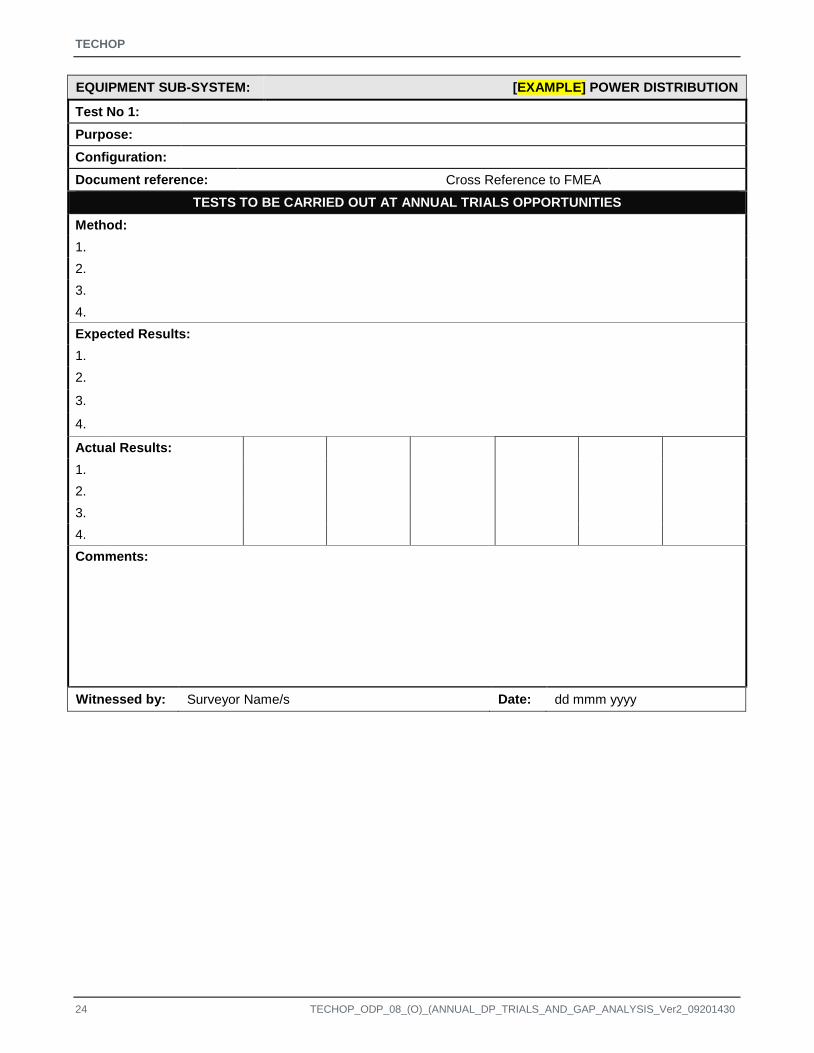
APPENDIX A TEST SHEET FOR USE AT ANNUAL TRIALS - M191
A complete example Annual DP Trials template is provided in IMCA M190. The test sheets below can be used for recording results for MODUs according to IMCA M191.
TECHOP_ODP_08_(O)_(ANNUAL_DP_TRIALS_AND_GAP_ANALYSIS_Ver2_09201430 23
TECHOP
EQUIPMENT SUB-SYSTEM: [EXAMPLE] POWER DISTRIBUTION
Test No 1: Purpose:
Configuration:
Document reference: Cross Reference to FMEA
TESTS TO BE CARRIED OUT AT ANNUAL TRIALS OPPORTUNITIES Method: 1. 2. 3. 4. Expected Results: 1. 2.
3.
4.
Actual Results: 1. 2. 3. 4. Comments:
Witnessed by: Surveyor Name/s Date: dd mmm yyyy
24 TECHOP_ODP_08_(O)_(ANNUAL_DP_TRIALS_AND_GAP_ANALYSIS_Ver2_09201430

TECHOP
APPENDIX B TEST SHEET FOR REVIEW OF PLANNED MAINTENANCE
A complete example Annual DP Trials template is provided in IMCA M190. The test sheets below can be used for recording results from the review of tests performed as part of planned maintenance for MODUs according to IMCA M191.
TECHOP_ODP_08_(O)_(ANNUAL_DP_TRIALS_AND_GAP_ANALYSIS_Ver2_09201430 25

TECHOP
EQUIPMENT SUB-SYSTEM: [EXAMPLE] POWER DISTRIBUTION
Test No 1: Purpose:
Configuration:
PM Job Number: Cross Reference to FMEA
FOR VERIFICATION BY REVIEW OF PLANNED MAINTENANCE Method: 1. 2. 3. 4. Expected Results: 1. 2.
3.
4.
Actual Results: 1. 2. 3. 4. Comments:
Witnessed by: Surveyor Name/s Date: dd mmm yyyy
26 TECHOP_ODP_08_(O)_(ANNUAL_DP_TRIALS_AND_GAP_ANALYSIS_Ver2_09201430

TECHOP
APPENDIX C EXAMPLE FINDINGS REGISTER FOR M191
TECHOP_ODP_08_(O)_(ANNUAL_DP_TRIALS_AND_GAP_ANALYSIS_Ver2_09201430 27

TECHOP
Findings Register
ID No
Test No. Findings Date
Raised Category Action by vessel owner
Resp. Person
Date Closed Remarks
28 TECHOP_ODP_08_(O)_(ANNUAL_DP_TRIALS_AND_GAP_ANALYSIS_Ver2_09201430
TECHOP
APPENDIX D ANNUAL TRIALS GAP ANALYSIS
TECHOP_ODP_08_(O)_(ANNUAL_DP_TRIALS_AND_GAP_ANALYSIS_Ver2_09201430 29

TECHOP
D.1 GUIDE TO COMPLETING THE GAP ANALYSIS TABLE 1. Execution of this gap analysis requires a detailed knowledge of the vessel’s DP FMEA.
2. The first table in the checklist is entitled ‘Review of Preamble’ and is intended to determine whether the introduction to the Annual DP Trials report and the test sheets includes the necessary general information on power plant and control system configuration etc.
3. The table on ’Review of Content’ examines the tests in the Annual DP Trials programme for evidence of the various test categories which should be included. These are listed in Column 1:
4. The sections which follow apply to the various test categories which should be included in the program.
• Performance.
• Standby redundancy.
• Protection.
• Detection.
• Control modes.
• Fail safe condition of thrusters.
5. Within each test category, the basic principle / objective that must be achieved is stated in the first row under the column entitled ‘Test Description’ followed by examples of systems or functions that should be tested and should therefore be present in the Annual DP Trials programme under review.
6. The column entitled ‘Cross Reference’ is intended to provide a link to the relevant section test number.
7. The four columns headed ‘Application’ indicate whether each test / issue is applicable to vessels operating with open busties, closed busties, DP Class 3 vessels or combinations of these.
8. The column marked ‘Planned Maint’ indicates whether this test might be suitable for execution as part of planned maintenance work but the Annual DP Trials should have test sheets with cross reference to all tests performance as part of planned maintenance.
9. The column titled Yes/No/Partial/NA is completed by shading in the cells Red, Yellow, Green or Grey depending on whether the test or issue is fully addressed, partially addressed, not addressed or not applicable to the annual trials program of the subject vessel.
10. The ‘Not Applicable’ entries can be subtracted from the total and the relative percentages of Reds, Yellows and Greens presented in a summary report along with a copy of the completed gap analysis table.
11. The column marked ‘Concerns’ is provided to record comments on the annual trials tests. In the paper copy of the checklist included with this TECHOP this column has been used to provide information on the consequences of not carrying out each of the test categories as part of a DP vessel’s annual trials programme. This column is blank in the XL spread sheet version of the checklist which accompanies this TECHOP.
30 TECHOP_ODP_08_(O)_(ANNUAL_DP_TRIALS_AND_GAP_ANALYSIS_Ver2_09201430

TECHOP
D.2 REVIEW OF PREAMBLE ANNUAL TRIALS GAP ANALYSIS - TRIALS DOCUMENT NUMBER AXXXXX-A
SYSTEM ID NO.
CROSS REFERENCE TO TRIALS PROGRAM
YES / PARTIAL / NO /
NOT APPLICABLE GREEN / YELLOW /
RED / GREY
CONCERN
Is worst case failure design intent identified? 1
Does it refer to the FMEA to identify the redundant equipment groups?
2
Follows IMCA M190/M212 guidelines for test objectives?
3
Does the report identify the time, date and location of the trials along with the weather conditions?
4
Details of machinery configuration provided 5
Configuration for CAM and TAM identified. 6
Does the annual trials report provide evidence that the DP system is being maintained in good order by providing a maintenance summary or suitable equivalent as required by IMO MSC 645 Section 5.1.1 Item 3
7
Test sheets identify correct configuration for test? Busties, generators and thrusters online?
8
Thruster configuration – Variable, bias, fixed etc.
9
Test sheets indicate where tests are configuration sensitive and must be repeated in each configuration.
10
Test sheets identify test location, e.g. alongside, on full auto DP, in deep water
11
Does the report contain relevant details of the previous annual trials?
12
Are the findings itemised in IMCA M190/M212 format?
13
Does the trials report conclude that the vessel meets requirements of its equipment class?
14
TECHOP_ODP_08_(O)_(ANNUAL_DP_TRIALS_AND_GAP_ANALYSIS_Ver2_09201430 31

TECHOP
D.3 REVIEW OF CONTENT ANNUAL TRIALS GAP ANALYSIS - TRIALS DOCUMENT NUMBER AXXXXX-A
DESCRIPTION APPLICATION GAP ANALYSIS
TEST CATEGORY TEST DESCRIPTION ID
NO. CLOSED BUSTIE
OPERATION
OPEN BUSTIE
OPERATION
DP CLASS
3 PLANNED
MAINT CROSS
REFERENCE TO TEST NO.
YES / PARTIAL /
NO / NOT
APPLICABLE GREEN /
YELLOW / RED / GREY
CONCERNS & NOTES
Performance
Does the Annual DP Trials program identify and test all those elements of the DP systems that may exhibit deteriorating performance?
1 Redundant elements must be present in number and capacity.
Generator 100% test 2
Vessel may lose position on failure of one redundant machinery group because the other has insufficient power.
Thruster 100% tests 3
Vessel may lose position on failure of one redundant machinery group because the other has insufficient Thrust
Network throughput test 4
If both networks are not capable of carrying all the traffic the vessel will lose position if one network fails
32 TECHOP_ODP_08_(O)_(ANNUAL_DP_TRIALS_AND_GAP_ANALYSIS_Ver2_09201430
TECHOP
ANNUAL TRIALS GAP ANALYSIS - TRIALS DOCUMENT NUMBER AXXXXX-A
DESCRIPTION APPLICATION GAP ANALYSIS
TEST CATEGORY TEST DESCRIPTION ID
NO. CLOSED BUSTIE
OPERATION
OPEN BUSTIE
OPERATION
DP CLASS
3 PLANNED
MAINT CROSS
REFERENCE TO TEST NO.
YES / PARTIAL /
NO / NOT
APPLICABLE GREEN /
YELLOW / RED / GREY
CONCERNS & NOTES
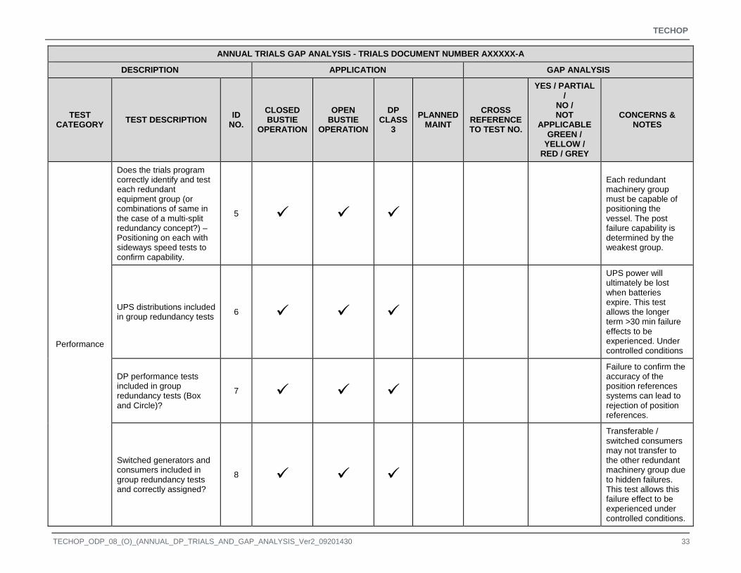
Performance
Does the trials program correctly identify and test each redundant equipment group (or combinations of same in the case of a multi-split redundancy concept?) – Positioning on each with sideways speed tests to confirm capability.
5
Each redundant machinery group must be capable of positioning the vessel. The post failure capability is determined by the weakest group.
UPS distributions included in group redundancy tests 6
UPS power will ultimately be lost when batteries expire. This test allows the longer term >30 min failure effects to be experienced. Under controlled conditions
DP performance tests included in group redundancy tests (Box and Circle)?
7
Failure to confirm the accuracy of the position references systems can lead to rejection of position references.
Switched generators and consumers included in group redundancy tests and correctly assigned?
8
Transferable / switched consumers may not transfer to the other redundant machinery group due to hidden failures. This test allows this failure effect to be experienced under controlled conditions.
TECHOP_ODP_08_(O)_(ANNUAL_DP_TRIALS_AND_GAP_ANALYSIS_Ver2_09201430 33

TECHOP
ANNUAL TRIALS GAP ANALYSIS - TRIALS DOCUMENT NUMBER AXXXXX-A
DESCRIPTION APPLICATION GAP ANALYSIS
TEST CATEGORY TEST DESCRIPTION ID
NO. CLOSED BUSTIE
OPERATION
OPEN BUSTIE
OPERATION
DP CLASS
3 PLANNED
MAINT CROSS
REFERENCE TO TEST NO.
YES / PARTIAL /
NO / NOT
APPLICABLE GREEN /
YELLOW / RED / GREY
CONCERNS & NOTES
Performance
UPS battery endurance? 9
UPS batteries allow monitoring to be maintained when main power systems fail and an orderly handover of control. Failure to ensure battery capacity allows the full effect of the failure to develop more rapidly.
Physical separation included in group redundancy tests for DP Class 3?
10
Failure to confirm that each redundant group has sufficient capacity is a potential hidden failure leading to loss of position if one redundant group fails.
Standby Redundancy
Does the Annual DP Trials program correctly identify and tests elements of switched redundancy upon which the redundancy concept depends
11
If the redundancy concept depends upon switched or standby redundancy then position will be lost if the standby redundancy fails to operate on demand.
34 TECHOP_ODP_08_(O)_(ANNUAL_DP_TRIALS_AND_GAP_ANALYSIS_Ver2_09201430

TECHOP
ANNUAL TRIALS GAP ANALYSIS - TRIALS DOCUMENT NUMBER AXXXXX-A
DESCRIPTION APPLICATION GAP ANALYSIS
TEST CATEGORY TEST DESCRIPTION ID
NO. CLOSED BUSTIE
OPERATION
OPEN BUSTIE
OPERATION
DP CLASS
3 PLANNED
MAINT CROSS
REFERENCE TO TEST NO.
YES / PARTIAL /
NO / NOT
APPLICABLE GREEN /
YELLOW / RED / GREY
CONCERNS & NOTES
Standby Redundancy
Does the Annual DP Trials program correctly identify protective functions designed to prevent fault transfer in standby or transferable equipment and test them?
12
Switched or standby machinery often forms a common point between redundant equipment groups and requires protective functions to prevent fault transfer. Failure to prove these protective functions can allow more than one redundant equipment group to be affected by a single failure. Loss of position may occur.
Changeover of DP controllers 13
There have been several instances of backup DP controllers failing to take over from the online controller due to hidden failures or software errors. Loss of position occurs.
Duty / standby pumps 14
Complete failure of auxiliary system in some designs – Loss of position / blackout.
Thruster transfer 15 Insufficient thrust leading to loss of position.
TECHOP_ODP_08_(O)_(ANNUAL_DP_TRIALS_AND_GAP_ANALYSIS_Ver2_09201430 35

TECHOP
ANNUAL TRIALS GAP ANALYSIS - TRIALS DOCUMENT NUMBER AXXXXX-A
DESCRIPTION APPLICATION GAP ANALYSIS
TEST CATEGORY TEST DESCRIPTION ID
NO. CLOSED BUSTIE
OPERATION
OPEN BUSTIE
OPERATION
DP CLASS
3 PLANNED
MAINT CROSS
REFERENCE TO TEST NO.
YES / PARTIAL /
NO / NOT
APPLICABLE GREEN /
YELLOW / RED / GREY
CONCERNS & NOTES
Standby Redundancy Generator start / transfer 16
Insufficient thrust leading to loss of position or disruption of industrial equipment.
Protection
Does the annual trials program correctly identify and test all the protective functions upon which redundancy / fault tolerance depends?
17
All protective functions are potential hidden failures. Failure to confirm the correct operation of protective functions can lead to failure effects greater than predicted
Does the Annual DP trials program correctly identify the Power Management System as a protective function and tests it in all appropriate power plant configurations.
18
The power management system is essentially a complex protective function designed to maintain continuity of power supply to the thrusters and other essential systems. If it fails in this objective it should attempt to restore power. Failure to confirm the correct operation of the PMS can lead failure effects > WCFDI
• Load dependent starting 19
Increased risk of industrial system and thruster phase back.
36 TECHOP_ODP_08_(O)_(ANNUAL_DP_TRIALS_AND_GAP_ANALYSIS_Ver2_09201430

TECHOP
ANNUAL TRIALS GAP ANALYSIS - TRIALS DOCUMENT NUMBER AXXXXX-A
DESCRIPTION APPLICATION GAP ANALYSIS
TEST CATEGORY TEST DESCRIPTION ID
NO. CLOSED BUSTIE
OPERATION
OPEN BUSTIE
OPERATION
DP CLASS
3 PLANNED
MAINT CROSS
REFERENCE TO TEST NO.
YES / PARTIAL /
NO / NOT
APPLICABLE GREEN /
YELLOW / RED / GREY
CONCERNS & NOTES
Protection
• Alarm start 20
Step load to power system when generators trips. Phase back of industrial equipment
• phase back of industrial consumers 21
Thrusters will phase back before the industrial consumers leading to loss of position
• Thruster phase back 22
Blackout may occur if thruster phase back is ineffective and fails to act in an overload or assist with poor load acceptance.
• Preferential trips 23
Premature phase back of industrial consumers or thrusters in worst case scenario leading to loss of position
• Industrial equipment interface – Power available. Regenerated power control etc.
24
Failure to control regenerated power can lead to blackout in low load conditions
Blackout restart and recovery (full and partial) 25
Blackout recovery is a risk mitigation measure
TECHOP_ODP_08_(O)_(ANNUAL_DP_TRIALS_AND_GAP_ANALYSIS_Ver2_09201430 37

TECHOP
ANNUAL TRIALS GAP ANALYSIS - TRIALS DOCUMENT NUMBER AXXXXX-A
DESCRIPTION APPLICATION GAP ANALYSIS
TEST CATEGORY TEST DESCRIPTION ID
NO. CLOSED BUSTIE
OPERATION
OPEN BUSTIE
OPERATION
DP CLASS
3 PLANNED
MAINT CROSS
REFERENCE TO TEST NO.
YES / PARTIAL /
NO / NOT
APPLICABLE GREEN /
YELLOW / RED / GREY
CONCERNS & NOTES
Protection
Is blackout recovery initiated by a realistic fault simulation?
26
Experience confirms that blackout recovery systems often perform as expected when the power plant is blacked out in a graceful way for test purposes but fail to recover the power plant in response to a real fault.
Does the Annual DP Trials program identify and test protective functions that reject errant position references and sensors.
27
Failure to reject a faulty reference system or sensor can lead to a drive off. Vessel with annual HIL test notation have access to more effective means of achieving this test. For vessels without this, suitable methods include serial link failure, applying offsets etc.
38 TECHOP_ODP_08_(O)_(ANNUAL_DP_TRIALS_AND_GAP_ANALYSIS_Ver2_09201430

TECHOP
ANNUAL TRIALS GAP ANALYSIS - TRIALS DOCUMENT NUMBER AXXXXX-A
DESCRIPTION APPLICATION GAP ANALYSIS
TEST CATEGORY TEST DESCRIPTION ID
NO. CLOSED BUSTIE
OPERATION
OPEN BUSTIE
OPERATION
DP CLASS
3 PLANNED
MAINT CROSS
REFERENCE TO TEST NO.
YES / PARTIAL /
NO / NOT
APPLICABLE GREEN /
YELLOW / RED / GREY
CONCERNS & NOTES
Protection Protection against network storms. 28
Network storms are a potential common mode failure capable of causing a drift off. All modern networks are fitted with protection against this type of failure. This protection must be checked periodically to confirm it is operational and that alarms to indicate that it is operating are working.
TECHOP_ODP_08_(O)_(ANNUAL_DP_TRIALS_AND_GAP_ANALYSIS_Ver2_09201430 39
TECHOP
ANNUAL TRIALS GAP ANALYSIS - TRIALS DOCUMENT NUMBER AXXXXX-A
DESCRIPTION APPLICATION GAP ANALYSIS
TEST CATEGORY TEST DESCRIPTION ID
NO. CLOSED BUSTIE
OPERATION
OPEN BUSTIE
OPERATION
DP CLASS
3 PLANNED
MAINT CROSS
REFERENCE TO TEST NO.
YES / PARTIAL /
NO / NOT
APPLICABLE GREEN /
YELLOW / RED / GREY
CONCERNS & NOTES
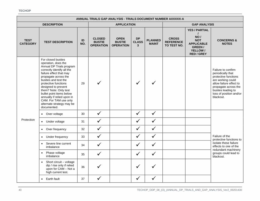
Protection
For closed busties operation, does the Annual DP Trials program correctly identify all the failure effect that may propagate across the busties and test the protective functions designed to prevent them? Note: Only test bullet point items below annually if relied upon in CAM. For TAM use only alternate strategy may be documented.
29
Failure to confirm periodically that protective functions are working could allow failure effect to propagate across the busties leading to loss of position and/or blackout.
• Over voltage 30
Failure of the protective functions to isolate these failure effects to one of the redundant machinery groups could lead to blackout.
• Under voltage 31
• Over frequency 32
• Under frequency 33
• Severe line current imbalance 34
• Phase voltage imbalance 35
• Short circuit – voltage dip / rise only if relied upon for CAM – Not a high current test.
36
• Earth fault 37
40 TECHOP_ODP_08_(O)_(ANNUAL_DP_TRIALS_AND_GAP_ANALYSIS_Ver2_09201430

TECHOP
ANNUAL TRIALS GAP ANALYSIS - TRIALS DOCUMENT NUMBER AXXXXX-A
DESCRIPTION APPLICATION GAP ANALYSIS
TEST CATEGORY TEST DESCRIPTION ID
NO. CLOSED BUSTIE
OPERATION
OPEN BUSTIE
OPERATION
DP CLASS
3 PLANNED
MAINT CROSS
REFERENCE TO TEST NO.
YES / PARTIAL /
NO / NOT
APPLICABLE GREEN /
YELLOW / RED / GREY
CONCERNS & NOTES
Protection
• Severe harmonic distortion 38
• Active power imbalance (kW) 39
• Reactive power imbalance (kVAr) 40
• Crash synchronisation Note this is a test of mitigating measures only eg check sync)
41
DP Alert 42
Risk of failure to promptly initiate emergency response to loss of position
Thruster emergency stops 43
Inability to stop a thruster which has failed to full thrust resulting in drive off
TECHOP_ODP_08_(O)_(ANNUAL_DP_TRIALS_AND_GAP_ANALYSIS_Ver2_09201430 41

TECHOP
ANNUAL TRIALS GAP ANALYSIS - TRIALS DOCUMENT NUMBER AXXXXX-A
DESCRIPTION APPLICATION GAP ANALYSIS
TEST CATEGORY TEST DESCRIPTION ID
NO. CLOSED BUSTIE
OPERATION
OPEN BUSTIE
OPERATION
DP CLASS
3 PLANNED
MAINT CROSS
REFERENCE TO TEST NO.
YES / PARTIAL /
NO / NOT
APPLICABLE GREEN /
YELLOW / RED / GREY
CONCERNS & NOTES
Detection
Does the trials program correctly identify and test all alarms required to reveal hidden failures, the onset of more severe failure effects or initiate operator intervention?
44
Failure to detect a hidden failure means that the vessel is operating in a non-fault tolerant condition. The next failure could cause a loss of position. Failure to detect the onset of a minor condition may allow it to develop to the point where the failure effects are catastrophic with potential for blackout and/or loss of position.
Offline / Backup DP controller 45
• UPS alarms for ‘on batteries’ and ‘in bypass’
46
• Seawater cooling pressure and/or flow 47
• Low fuel oil level 48
42 TECHOP_ODP_08_(O)_(ANNUAL_DP_TRIALS_AND_GAP_ANALYSIS_Ver2_09201430

TECHOP
ANNUAL TRIALS GAP ANALYSIS - TRIALS DOCUMENT NUMBER AXXXXX-A
DESCRIPTION APPLICATION GAP ANALYSIS
TEST CATEGORY TEST DESCRIPTION ID
NO. CLOSED BUSTIE
OPERATION
OPEN BUSTIE
OPERATION
DP CLASS
3 PLANNED
MAINT CROSS
REFERENCE TO TEST NO.
YES / PARTIAL /
NO / NOT
APPLICABLE GREEN /
YELLOW / RED / GREY
CONCERNS & NOTES
Detection
• Low air pressure alarm 49
Failure to detect a hidden failure means that the vessel is operating in a non-fault tolerant condition. The next failure could cause a loss of position. Failure to detect the onset of a minor condition may allow it to develop to the point where the failure effects are catastrophic with potential for blackout and/or loss of position.
• High cooling water temperature 50
• Engine alarm conditions 51
• Failure of supplies to standby redundancy 52
• Alarms to indicate failure of thruster emergency stops
53
• Alarms to indicate network failure 54
• Alarms to indicate failure of reference systems and sensors
55
Control Modes
Does the Annual DP Trials program exercise infrequently used control modes?
56 Failure to test infrequently used control modes could hamper or prevent emergency response if the automatic control systems fails
• Independent Joystick 57
• Manual thruster control levers 58
• Back-up DP control system 59
TECHOP_ODP_08_(O)_(ANNUAL_DP_TRIALS_AND_GAP_ANALYSIS_Ver2_09201430 43

TECHOP
ANNUAL TRIALS GAP ANALYSIS - TRIALS DOCUMENT NUMBER AXXXXX-A
DESCRIPTION APPLICATION GAP ANALYSIS
TEST CATEGORY TEST DESCRIPTION ID
NO. CLOSED BUSTIE
OPERATION
OPEN BUSTIE
OPERATION
DP CLASS
3 PLANNED
MAINT CROSS
REFERENCE TO TEST NO.
YES / PARTIAL /
NO / NOT
APPLICABLE GREEN /
YELLOW / RED / GREY
CONCERNS & NOTES
Fail Safe of Thrusters
Does the trials program identify and tests protective functions which ensure thrusters fail safe in respect of thrust magnitude?
60 Failure to test protective functions designed to ensure thrusters fail safe could increase the risk of a drive off. Guidance on the test frequency is given in Section 3.6 and IMCA M190.
Does the trials program identify and tests protective functions which ensure thrusters fail safe in respect of thrust direction?
61
Cross Reference
Do the test sheets contain cross reference to relevant section of the FMEA?
62
Do the test sheets for tests that can be carried out as part of planned maintenance have reference to PM system job number?
63
44 TECHOP_ODP_08_(O)_(ANNUAL_DP_TRIALS_AND_GAP_ANALYSIS_Ver2_09201430