technical brochure electrically operated … brochure electrically operated expansion valves, type...
TRANSCRIPT
MAKING MODERN LIVING POSSIBLE
1DKRCC.PD.VD1.C2.02 / 520H5239
Technical brochure
Electrically operated expansion valves, type ETS
Features Precise positioning for optimal control of liquid injection.ETS 12,5, ETS 25, ETS 50 and ETS 100 are designed for HFC/HCFC conditions including R410A, providing 45.5 bar (659.9 psig) working pressure. ETS 250 and 400 are designed for HFC/HCFC conditions, providing 34 bar (493 psig) working pressure.Balanced design providing bi-flow operation as well as solenoid tight shut-off function in both flow directions at MOPD 33 bar (478.6 psig).
EKC316A, 312 and EKD316 are examples of Danfoss controllers with drivers matching the ETS needs.ETS 50 and 100 have bi-metal connections providing "waterless brazing", improved process and productivity.ETS 50 to 400 are all designed with built-in sight glass.Cable and connector assemblies as accessories.For manual operation and service of ETS valves an AST-g service driver is available. For further information please contact Danfoss.
Description
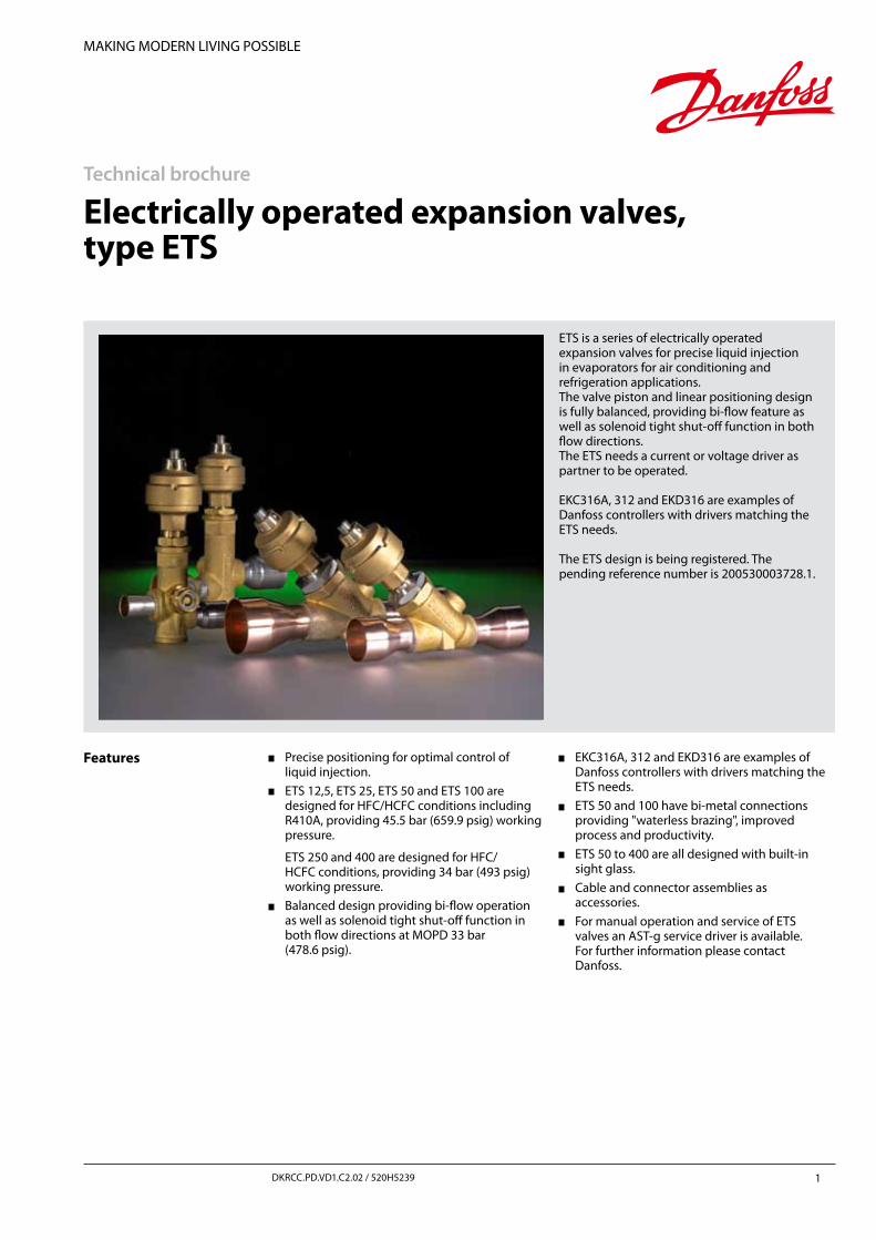
ETS is a series of electrically operated expansion valves for precise liquid injection in evaporators for air conditioning and refrigeration applications.The valve piston and linear positioning design is fully balanced, providing bi-flow feature as well as solenoid tight shut-off function in both flow directions.The ETS needs a current or voltage driver as partner to be operated.
EKC316A, 312 and EKD316 are examples ofDanfoss controllers with drivers matching the ETS needs.
The ETS design is being registered. The pending reference number is 200530003728.1.
Technical brochure Electrically operated expansion valves, type ETS
2 DKRCC.PD.VD1.C2.02 / 520H5239
Technical data
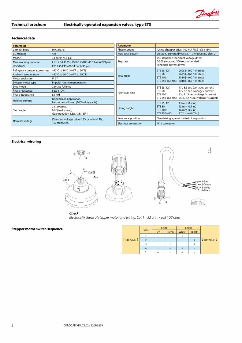
↑ CLOSING ↑
STEPCoil I Coil II
↓ OPENING ↓
Red Green White Black1 + - + -2 + - - +3 - + - +4 - + + -1 + - + -
CheckElectrically check of stepper motor and wiring. Coil I = 52 ohm - coil II 52 ohm
ParameterCompatibility HFC, HCFCCE marking YesMOPD 33 bar (478.6 psi)Max. working pressure(PS/MWP)
ETS12.5/ETS25/ETS50/ETS100: 45.5 bar (659.9 psi)ETS 250/ETS 400:34 bar (493 psi)
Refrigerant temperature range –40°C to 10°C (–40°F to 50°F)Ambient temperature –40°C to 60°C (–40°F to 140°F)Motor enclosure IP 67Stepper motor type Bi-polar - permanent magnetStep mode 2 phase full stepPhase resistance 52Ω ±10%Phase inductance 85 mH
Holding current Depends on application.Full current allowed (100% duty cycle)
Step angle7.5° (motor), 0.9° (lead screw),Gearing ration 8.5:1. (38/13)2:1
Nominal voltage (Constant voltage drive) 12 V dc -4% +15%, 150 steps/sec.
ParameterPhase current (Using chopper drive) 100 mA RMS -4% +15%, Max. total power Voltage / current drive: 5.5 / 1.3 W (UL: NEC class 2)
Step rate150 steps/sec. (constant voltage drive)0-300 steps/sec. 300 recommended (chopper current drive)
Total steps
ETS 25, 12˝: 2625 [+160 / -0] stepsETS 50: 2625 [+160 / -0] stepsETS 100: 3530 [+160 / -0] steps ETS 250 and 400: 3810 [+160 / -0] steps
Full travel time
ETS 25, 12˝: 17 / 8.5 sec. (voltage / current)ETS 50: 17 / 8.5 sec. (voltage / current)ETS 100: 23 / 11.5 sec. (voltage / current)ETS 250 and 400: 25.4 / 12.7 sec. (voltage / current)
Lifting height
ETS 25, 12˝: 13 mm (0.5 in.)ETS 50: 13 mm (0.5 in.)ETS 100: 16 mm (0.6 in.)ETS 250-400: 17.2 mm (0.7 in.)
Reference position Overdriving against the full close position
Electrical connection M12 connector
Stepper motor switch sequence
Electrical wirering

Technical brochure Electrically operated expansion valves, type ETS
3DKRCC.PD.VD1.C2.02 / 520H5239
ETS
Valve operation
The ETS valves operate modulating by electronically controlled activation of the AST stepper motor. The motor is a type 2-phase bi-polar, which stays in position, unless power pulses from a driver initiate the two discrete sets of motor stator windings for rotation in either directions.
The direction depends on the phase relationship of the power pulses, which number again is decisive for the travel.
The motor is operating the spindle, which rotating movements are transformed into linear motion by the transmission in the cage assembly.
The AST motor housing has a glass sealed M12connection as standard, which can be connected with customized cable and plug/socket combinations.
ETS design is fully power balanced, giving identical bi-flow performance capabilities and nearby identical maximum capacities.
The port design includes a shut-off function with "solenoid" tightness in both flow directions. Closed position is also the mechanical stop acting as reference point to reset the controller.
Operating the ETS series requires a controller with either 12 V dc voltage drive (5.5 W) or using chopper drive (100 mA RMS).
Danfoss EKC316A, EKC312 and EED316 are examples of qualified controllers.
Design
1. M12 connection 2. Glass seal 3. AST motor housing 4. Stepper motor 5. Bearing 6. Spindle 7. Cone andlead nut
ETS 25, 12½, straight and angleway
Product type ETSFile name 34G45Date 2011.01.11
Valve / Actuator type ETS / AST-g
Danfoss
93G18.13
Product type ETSFile name 34G46Date 2011.01.11
Technical brochure Electrically operated expansion valves, type ETS
4 DKRCC.PD.VD1.C2.02 / 520H5239
Valve operation (Cont.)
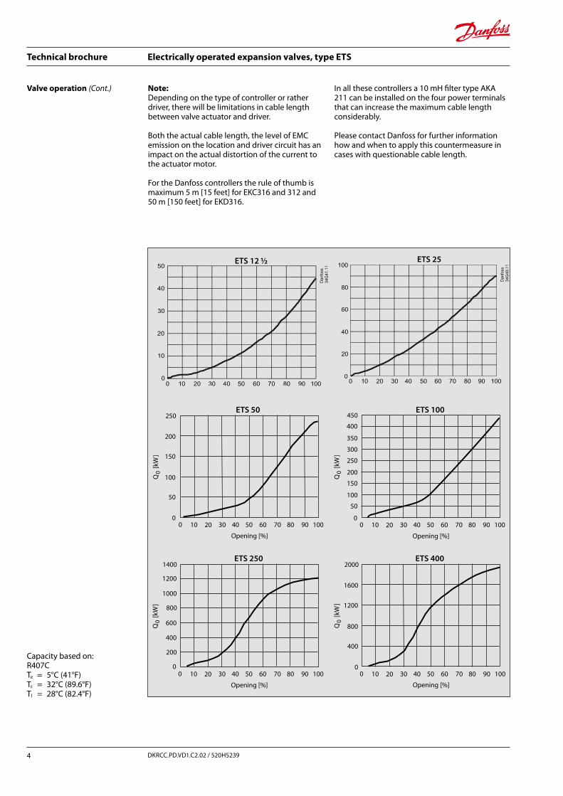
Capacity based on:R407CTe = 5°C (41°F)Tc = 32°C (89.6°F)Tl = 28°C (82.4°F)
Note: Depending on the type of controller or rather driver, there will be limitations in cable length between valve actuator and driver.
Both the actual cable length, the level of EMC emission on the location and driver circuit has an impact on the actual distortion of the current to the actuator motor.
For the Danfoss controllers the rule of thumb is maximum 5 m [15 feet] for EKC316 and 312 and 50 m [150 feet] for EKD316.
In all these controllers a 10 mH filter type AKA 211 can be installed on the four power terminals that can increase the maximum cable length considerably.
Please contact Danfoss for further information how and when to apply this countermeasure in cases with questionable cable length.
250
200
150
100
50
00 10 20 30 40 50 60 70 80 90 100
Q
[kW
]0
Opening [%]
450
400
350
300
00 10 20 30 40 50 60 70 80 90 100
250
200
150
100
50
Q
[kW
]0
Opening [%]
1400
1200
1000
800
0 10 20 30 40 50 60 70 80 90 100
600
400
200
0
Q
[kW
]0
Opening [%]
2000
1600
1200
800
400
00 10 20 30 40 50 60 70 80 90 100
Q
[kW
]0
Opening [%]
ETS 12 ½ ETS 25
ETS 50 ETS 100
ETS 250 ETS 400
Technical brochure Electrically operated expansion valves, type ETS
5DKRCC.PD.VD1.C2.02 / 520H5239
The corrected evaporator capacity thus becomes 500 : 1.15 = 435 kW (124 TR)
As the ETS series has a wide capacity area from the table values down to 10% of these, the sizing is not critical.
Under the given circumstances ETS 100 can operate between 496 kW (142 TR) and 56 kW (14 TR).
Bi-flow capacities (opposite of normal flow direction) are the same for ETS 50, whereas ETS 100 has 10% less from normal flow direction.
Example: Refrigerant: R410A
Evaporating temperature:te = +10°C (50°F)pe = 9.8 bar (142 psig)
Condensing temperature:tc = 40°C (104°F)pc = 23 bar (330 psig)
Pressure drop in valve:∆p = 23 – 9.8 = 13.2 bar (192 psig)
Subcooling: ∆tsub = 15 K (27°F)
Evaporator capacity: 500 kW (143 TR)
Correction value from table: 1.15
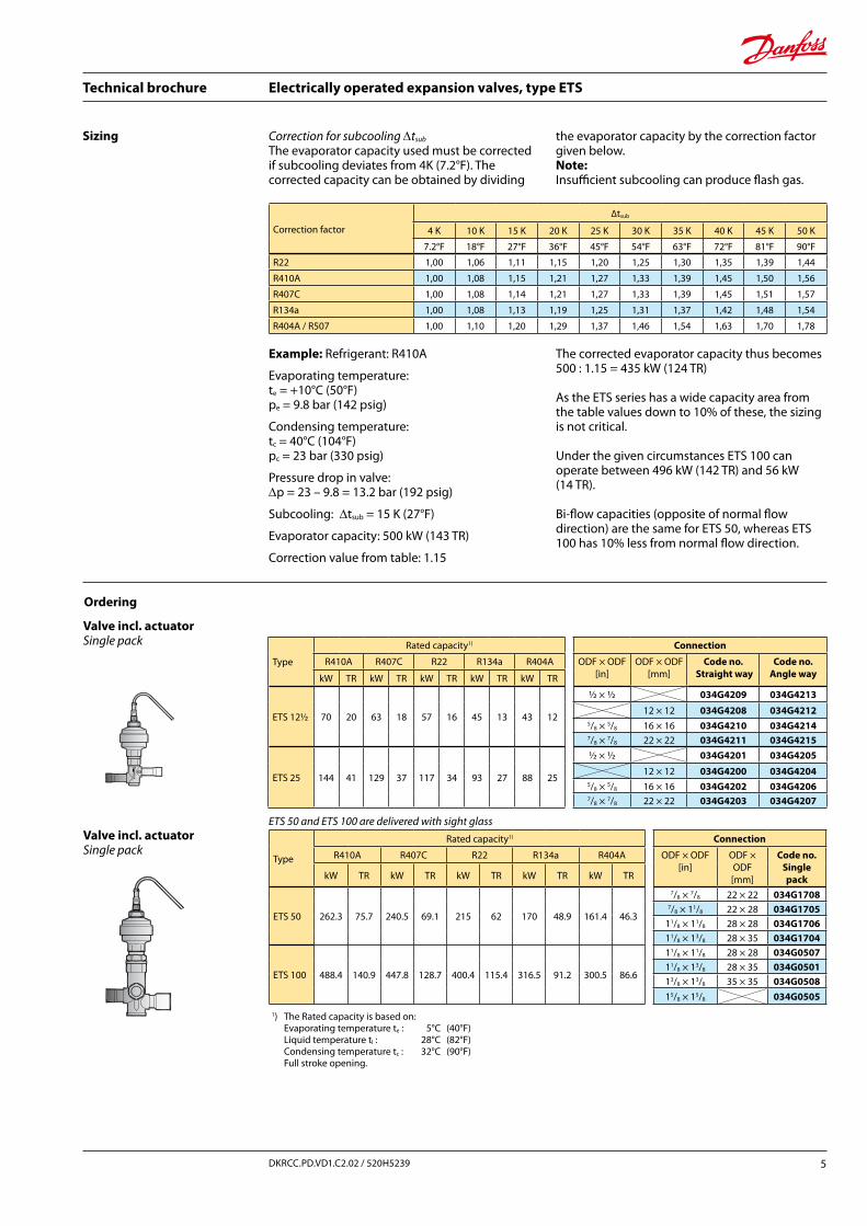
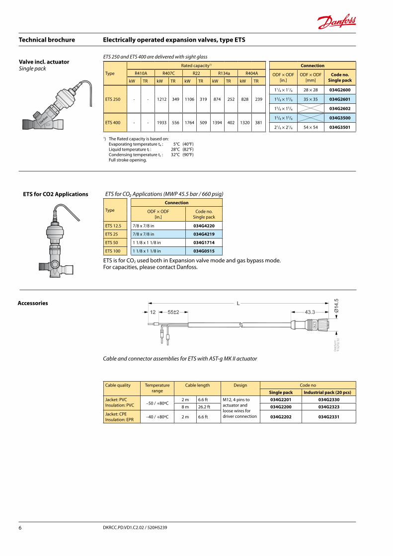
Valve incl. actuator Single pack
1) The Rated capacity is based on: Evaporating temperature te : 5°C (40°F) Liquid temperature tl : 28°C (82°F) Condensing temperature tc : 32°C (90°F) Full stroke opening.
Type
Rated capacity1) Connection
R410A R407C R22 R134a R404A ODF × ODF[in]
ODF × ODF[mm]
Code no. Straight way
Code no.Angle waykW TR kW TR kW TR kW TR kW TR
ETS 12½ 70 20 63 18 57 16 45 13 43 12
½ × ½ 034G4209 034G4213
12 × 12 034G4208 034G42125/8 × 5/8 16 × 16 034G4210 034G42147/8 × 7/8 22 × 22 034G4211 034G4215
ETS 25 144 41 129 37 117 34 93 27 88 25
½ × ½ 034G4201 034G4205
12 × 12 034G4200 034G42045/8 × 5/8 16 × 16 034G4202 034G42067/8 × 7/8 22 × 22 034G4203 034G4207
Ordering
Valve incl. actuator Single pack
Type
Rated capacity1) Connection
R410A R407C R22 R134a R404A ODF × ODF[in]
ODF × ODF[mm]
Code no.Single pack kW TR kW TR kW TR kW TR kW TR
ETS 50 262.3 75.7 240.5 69.1 215 62 170 48.9 161.4 46.3
7/8 × 7/8 22 × 22 034G17087/8 × 11/8 22 × 28 034G1705
11/8 × 11/8 28 × 28 034G170611/8 × 13/8 28 × 35 034G1704
ETS 100 488.4 140.9 447.8 128.7 400.4 115.4 316.5 91.2 300.5 86.6
11/8 × 11/8 28 × 28 034G050711/8 × 13/8 28 × 35 034G050113/8 × 13/8 35 × 35 034G050815/8 × 15/8 034G0505
R22 1,00 1,06 1,11 1,15 1,20 1,25 1,30 1,35 1,39 1,44
R410A 1,00 1,08 1,15 1,21 1,27 1,33 1,39 1,45 1,50 1,56
R407C 1,00 1,08 1,14 1,21 1,27 1,33 1,39 1,45 1,51 1,57
R134a 1,00 1,08 1,13 1,19 1,25 1,31 1,37 1,42 1,48 1,54
R404A / R507 1,00 1,10 1,20 1,29 1,37 1,46 1,54 1,63 1,70 1,78
Sizing Correction for subcooling ∆tsub
The evaporator capacity used must be corrected if subcooling deviates from 4K (7.2°F). The corrected capacity can be obtained by dividing
the evaporator capacity by the correction factor given below.Note: Insufficient subcooling can produce flash gas.
Correction factor
∆tsub
4 K 10 K 15 K 20 K 25 K 30 K 35 K 40 K 45 K 50 K
7.2°F 18°F 27°F 36°F 45°F 54°F 63°F 72°F 81°F 90°F
ETS 50 and ETS 100 are delivered with sight glass
Technical brochure Electrically operated expansion valves, type ETS
6 DKRCC.PD.VD1.C2.02 / 520H5239
Type
Rated capacity1) Connection
R410A R407C R22 R134a R404A ODF × ODF [in.]
ODF × ODF [mm]
Code no. Single packkW TR kW TR kW TR kW TR kW TR
ETS 250 - - 1212 349 1106 319 874 252 828 239
11/8 × 11/8 28 × 28 034G2600
13/8 × 13/8 35 × 35 034G2601
15/8 × 15/8 034G2602
ETS 400 - - 1933 556 1764 509 1394 402 1320 38115/8 × 15/8 034G3500
21/8 × 21/8 54 × 54 034G3501
1) The Rated capacity is based on: Evaporating temperature te : 5°C (40°F) Liquid temperature tl : 28°C (82°F) Condensing temperature tc : 32°C (90°F) Full stroke opening.
Valve incl. actuator Single pack
Cable quality Temperaturerange
Cable length Design Code no
Single pack Industrial pack (20 pcs)
Jacket: PVCInsulation: PVC –50 / +80ºC
2 m 6.6 ft M12, 4 pins to actuator and loose wires for driver connection
034G2201 034G2330
8 m 26.2 ft 034G2200 034G2323
Jacket: CPEInsulation: EPR –40 / +80ºC 2 m 6.6 ft 034G2202 034G2331
Accessories
Cable and connector assemblies for ETS with AST-g MK II actuator
ETS for CO2 Applications ETS for CO₂ Applications (MWP 45.5 bar / 660 psig)
Type
Connection
ODF × ODF [in.]
Code no. Single pack
ETS 12.5 7/8 x 7/8 in 034G4220
ETS 25 7/8 x 7/8 in 034G4219
ETS 50 1 1/8 x 1 1/8 in 034G1714
ETS 100 1 1/8 x 1 1/8 in 034G0515
ETS is for CO2 used both in Expansion valve mode and gas bypass mode.For capacities, please contact Danfoss.
ETS 250 and ETS 400 are delivered with sight glass
Technical brochure Electrically operated expansion valves, type ETS
7DKRCC.PD.VD1.C2.02 / 520H5239
Type
Rated capacity1) Connection
R410A R407C R22 R134a R404A ODF × ODF [in.]
ODF × ODF [mm]
Code no. Single packkW TR kW TR kW TR kW TR kW TR
ETS 250 - - 1212 349 1106 319 874 252 828 239
11/8 × 11/8 28 × 28 034G2600
13/8 × 13/8 35 × 35 034G2601
15/8 × 15/8 034G2602
ETS 400 - - 1933 556 1764 509 1394 402 1320 38115/8 × 15/8 034G3500
21/8 × 21/8 54 × 54 034G3501
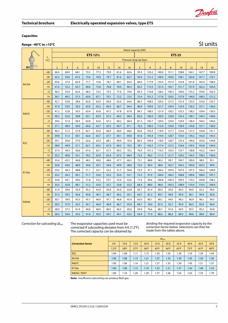
Correction for subcooling ∆tsub
Note: Insufficient subcooling can produce flash gas.
The evaporator capacities used must be corrected if subcooling deviates from 4 K (7.2°F).The corrected capacity can be obtained by
dividing the required evaporator capacity by the correction factor below. Selections can then be made from the tables above.
te
[°C]
Rated capacity [kW]
ETS 12½ ETS 25Pressure drop ∆p [bar]
2 4 6 8 10 12 14 16 2 4 6 8 10 12 14 16
R410A
–40 46.4 60.0 68.1 73.5 77.3 79.9 81.6 82.6 95.3 123.2 140.0 151.1 158.8 164.1 167.7 169.8
–30 45.2 59.0 67.3 73.0 76.9 79.7 81.6 82.7 92.9 121.2 138.4 150.0 158.1 163.8 167.7 170.1
–20 43.6 57.4 65.9 71.7 75.8 78.7 80.7 82.0 89.6 117.9 135.4 147.4 155.8 161.8 165.9 168.6
–10 41.6 55.2 63.7 69.6 73.8 76.8 78.9 80.3 85.5 113.5 131.0 143.1 151.7 157.9 162.2 165.0
–5 40.5 53.9 62.4 68.3 72.5 75.5 77.6 79.0 83.3 110.8 128.2 140.3 149.0 155.2 159.6 162.5
10 36.7 49.2 57.3 63.0 67.1 70.1 72.2 73.5 75.4 101.2 117.8 129.5 137.9 144.0 148.3 151.2
R407C
–40 42.1 52.8 58.6 62.0 63.9 64.9 65.0 64.6 86.5 108.5 120.5 127.5 131.4 133.3 133.6 132.7
–30 41.9 53.0 59.2 63.0 65.2 66.3 66.7 66.4 86.0 109.0 121.7 129.4 133.9 136.3 137.1 136.6
–20 41.2 52.8 59.3 63.4 65.8 67.2 67.8 67.8 84.7 108.5 121.9 130.2 135.3 138.2 139.4 139.3
–10 40.2 52.0 58.8 63.1 65.9 67.5 68.3 68.4 82.6 106.9 120.9 129.8 135.4 138.7 140.3 140.6
–5 39.6 51.4 58.4 62.8 65.6 67.3 68.2 68.4 81.3 105.7 120.0 129.0 134.9 138.4 140.2 140.6
10 37.1 48.9 56.0 60.6 63.7 65.5 66.7 67.1 76.3 100.5 115.0 124.6 130.9 134.8 137.1 138.0
R22
–40 40.2 51.3 57.9 62.1 65.0 66.9 68.0 68.6 82.6 105.5 118.9 127.7 133.6 137.5 139.8 141.1
–30 39.8 51.3 58.1 62.6 65.7 67.7 69.1 69.8 81.8 105.4 119.4 128.7 135.0 139.2 142.0 143.5
–20 39.1 50.8 57.9 62.6 65.9 68.1 69.6 70.4 80.3 104.4 118.9 128.7 135.4 140.0 143.0 144.8
–10 38.0 49.9 57.1 62.1 65.5 67.9 69.5 70.5 78.1 102.5 117.4 127.5 134.6 139.5 142.8 144.9
–5 37.4 49.3 56.6 61.6 65.1 67.5 69.2 70.2 76.9 101.2 116.3 126.5 133.7 138.8 142.2 144.4
10 35.2 46.8 54.1 59.2 62.9 65.4 67.2 68.4 72.3 96.2 111.3 121.7 129.2 134.5 138.2 140.6
R134a
–40 35.6 43.2 46.8 48.5 49.0 48.6 47.7 46.3 73.1 88.8 96.3 99.7 100.7 100.0 98.0 95.1
–30 35.8 44.0 48.0 50.0 50.7 50.6 49.9 48.6 73.5 90.4 98.6 102.7 104.2 104.0 102.5 99.9
–20 35.6 44.3 48.8 51.1 52.1 52.2 51.7 50.6 73.3 91.1 100.2 105.0 107.0 107.3 106.2 104.0
–10 35.2 44.3 49.1 51.7 53.0 53.3 53.0 52.1 72.3 91.0 100.9 106.2 108.8 109.6 108.9 107.1
–5 34.8 44.1 49.0 51.8 53.2 53.7 53.4 52.6 71.6 90.6 100.8 106.4 109.3 110.3 109.8 108.2
10 33.3 42.8 48.1 51.2 53.0 53.7 53.8 53.2 68.3 88.0 98.9 105.3 108.9 110.4 110.5 109.4
R404A
–40 31.9 39.6 43.4 45.2 45.9 45.8 45.0 43.8 65.7 81.4 89.2 93.0 94.3 94.0 92.5 90.0
–30 31.5 39.5 43.6 45.8 46.7 46.7 46.2 45.1 64.7 81.2 89.7 94.0 95.9 96.1 94.9 92.8
–20 30.7 39.0 43.3 45.7 46.9 47.1 46.8 45.9 63.0 80.1 89.1 94.0 96.3 96.9 96.1 94.3
–10 29.5 37.9 42.5 45.1 46.4 46.9 46.7 45.9 60.7 78.0 87.4 92.7 95.4 96.3 95.9 94.4
–5 28.9 37.3 41.9 44.6 46.0 46.5 46.3 45.6 59.4 76.6 86.1 91.6 94.5 95.5 95.2 93.8
10 26.5 34.6 39.2 41.9 43.5 44.1 44.1 43.5 54.4 71.0 80.5 86.2 89.3 90.6 90.6 89.4
Correction factor
∆tsub
4 K 10 K 15 K 20 K 25 K 30 K 35 K 40 K 45 K 50 K
7.2°F 18°F 27°F 36°F 45°F 54°F 63°F 72°F 81°F 90°F
R22 1.00 1.06 1.11 1.15 1.20 1.25 1.30 1.35 1.39 1.44
R410A 1.00 1.08 1.15 1.21 1.27 1.33 1.39 1.45 1.50 1.56
R407C 1.00 1.08 1.14 1.21 1.27 1.33 1.39 1.45 1.51 1.57
R134a 1.00 1.08 1.13 1.19 1.25 1.31 1.37 1.42 1.48 1.54
R404A / R507 1.00 1.10 1.20 1.29 1.37 1.46 1.54 1.63 1.70 1.78
Capacities
Range –40°C to +10°C SI units
Technical brochure Electrically operated expansion valves, type ETS
8 DKRCC.PD.VD1.C2.02 / 520H5239
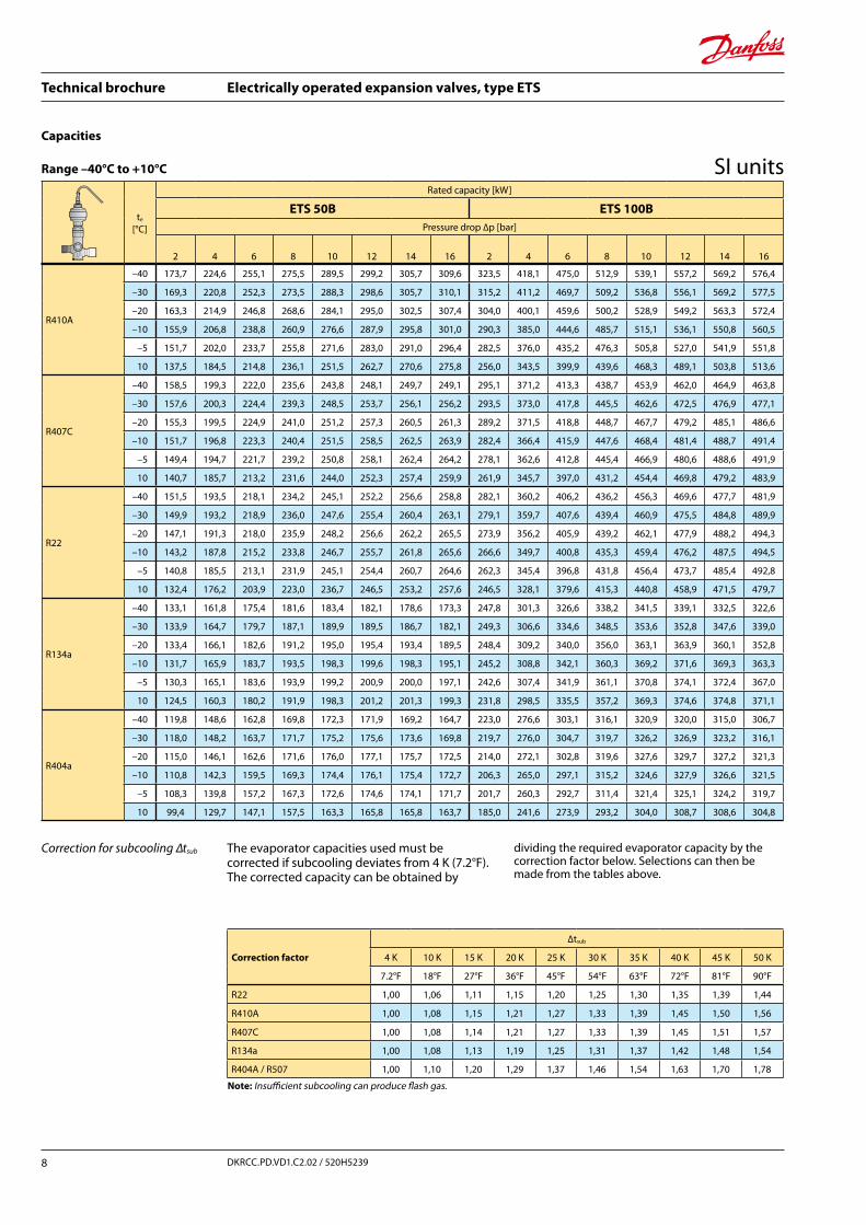
te
[°C]
Rated capacity [kW]
ETS 50B ETS 100BPressure drop ∆p [bar]
2 4 6 8 10 12 14 16 2 4 6 8 10 12 14 16
R22 1,00 1,06 1,11 1,15 1,20 1,25 1,30 1,35 1,39 1,44
R410A 1,00 1,08 1,15 1,21 1,27 1,33 1,39 1,45 1,50 1,56
R407C 1,00 1,08 1,14 1,21 1,27 1,33 1,39 1,45 1,51 1,57
R134a 1,00 1,08 1,13 1,19 1,25 1,31 1,37 1,42 1,48 1,54
R404A / R507 1,00 1,10 1,20 1,29 1,37 1,46 1,54 1,63 1,70 1,78
R410A
–40 173,7 224,6 255,1 275,5 289,5 299,2 305,7 309,6 323,5 418,1 475,0 512,9 539,1 557,2 569,2 576,4
–30 169,3 220,8 252,3 273,5 288,3 298,6 305,7 310,1 315,2 411,2 469,7 509,2 536,8 556,1 569,2 577,5
–20 163,3 214,9 246,8 268,6 284,1 295,0 302,5 307,4 304,0 400,1 459,6 500,2 528,9 549,2 563,3 572,4
–10 155,9 206,8 238,8 260,9 276,6 287,9 295,8 301,0 290,3 385,0 444,6 485,7 515,1 536,1 550,8 560,5
–5 151,7 202,0 233,7 255,8 271,6 283,0 291,0 296,4 282,5 376,0 435,2 476,3 505,8 527,0 541,9 551,8
10 137,5 184,5 214,8 236,1 251,5 262,7 270,6 275,8 256,0 343,5 399,9 439,6 468,3 489,1 503,8 513,6
R407C
–40 158,5 199,3 222,0 235,6 243,8 248,1 249,7 249,1 295,1 371,2 413,3 438,7 453,9 462,0 464,9 463,8
–30 157,6 200,3 224,4 239,3 248,5 253,7 256,1 256,2 293,5 373,0 417,8 445,5 462,6 472,5 476,9 477,1
–20 155,3 199,5 224,9 241,0 251,2 257,3 260,5 261,3 289,2 371,5 418,8 448,7 467,7 479,2 485,1 486,6
–10 151,7 196,8 223,3 240,4 251,5 258,5 262,5 263,9 282,4 366,4 415,9 447,6 468,4 481,4 488,7 491,4
–5 149,4 194,7 221,7 239,2 250,8 258,1 262,4 264,2 278,1 362,6 412,8 445,4 466,9 480,6 488,6 491,9
10 140,7 185,7 213,2 231,6 244,0 252,3 257,4 259,9 261,9 345,7 397,0 431,2 454,4 469,8 479,2 483,9
R22
–40 151,5 193,5 218,1 234,2 245,1 252,2 256,6 258,8 282,1 360,2 406,2 436,2 456,3 469,6 477,7 481,9
–30 149,9 193,2 218,9 236,0 247,6 255,4 260,4 263,1 279,1 359,7 407,6 439,4 460,9 475,5 484,8 489,9
–20 147,1 191,3 218,0 235,9 248,2 256,6 262,2 265,5 273,9 356,2 405,9 439,2 462,1 477,9 488,2 494,3
–10 143,2 187,8 215,2 233,8 246,7 255,7 261,8 265,6 266,6 349,7 400,8 435,3 459,4 476,2 487,5 494,5
–5 140,8 185,5 213,1 231,9 245,1 254,4 260,7 264,6 262,3 345,4 396,8 431,8 456,4 473,7 485,4 492,8
10 132,4 176,2 203,9 223,0 236,7 246,5 253,2 257,6 246,5 328,1 379,6 415,3 440,8 458,9 471,5 479,7
R134a
–40 133,1 161,8 175,4 181,6 183,4 182,1 178,6 173,3 247,8 301,3 326,6 338,2 341,5 339,1 332,5 322,6
–30 133,9 164,7 179,7 187,1 189,9 189,5 186,7 182,1 249,3 306,6 334,6 348,5 353,6 352,8 347,6 339,0
–20 133,4 166,1 182,6 191,2 195,0 195,4 193,4 189,5 248,4 309,2 340,0 356,0 363,1 363,9 360,1 352,8
–10 131,7 165,9 183,7 193,5 198,3 199,6 198,3 195,1 245,2 308,8 342,1 360,3 369,2 371,6 369,3 363,3
–5 130,3 165,1 183,6 193,9 199,2 200,9 200,0 197,1 242,6 307,4 341,9 361,1 370,8 374,1 372,4 367,0
10 124,5 160,3 180,2 191,9 198,3 201,2 201,3 199,3 231,8 298,5 335,5 357,2 369,3 374,6 374,8 371,1
R404a
–40 119,8 148,6 162,8 169,8 172,3 171,9 169,2 164,7 223,0 276,6 303,1 316,1 320,9 320,0 315,0 306,7
–30 118,0 148,2 163,7 171,7 175,2 175,6 173,6 169,8 219,7 276,0 304,7 319,7 326,2 326,9 323,2 316,1
–20 115,0 146,1 162,6 171,6 176,0 177,1 175,7 172,5 214,0 272,1 302,8 319,6 327,6 329,7 327,2 321,3
–10 110,8 142,3 159,5 169,3 174,4 176,1 175,4 172,7 206,3 265,0 297,1 315,2 324,6 327,9 326,6 321,5
–5 108,3 139,8 157,2 167,3 172,6 174,6 174,1 171,7 201,7 260,3 292,7 311,4 321,4 325,1 324,2 319,7
10 99,4 129,7 147,1 157,5 163,3 165,8 165,8 163,7 185,0 241,6 273,9 293,2 304,0 308,7 308,6 304,8
Correction for subcooling ∆tsub
Note: Insufficient subcooling can produce flash gas.
The evaporator capacities used must be corrected if subcooling deviates from 4 K (7.2°F).The corrected capacity can be obtained by
dividing the required evaporator capacity by the correction factor below. Selections can then be made from the tables above.
Correction factor
∆tsub
4 K 10 K 15 K 20 K 25 K 30 K 35 K 40 K 45 K 50 K
7.2°F 18°F 27°F 36°F 45°F 54°F 63°F 72°F 81°F 90°F
Capacities
Range –40°C to +10°C SI units
Technical brochure Electrically operated expansion valves, type ETS
9DKRCC.PD.VD1.C2.02 / 520H5239
R407C
–40 811 1017 1129 1195 1232 1249 1252 1244 1294 1622 1801 1905 1964 1992 1997 1984
–30 806 1022 1141 1213 1255 1277 1284 1280 1286 1629 1820 1934 2002 2037 2049 2041
–20 794 1017 1143 1220 1268 1295 1306 1305 1266 1621 1823 1947 2023 2065 2083 2082
–10 774 1002 1133 1216 1269 1300 1315 1317 1235 1598 1808 1940 2024 2073 2097 2101
–5 762 990 1124 1209 1264 1297 1314 1318 1215 1580 1793 1929 2016 2068 2095 2102
10 715 941 1078 1167 1226 1264 1285 1293 1141 1502 1719 1862 1956 2016 2049 2062
R22
–40 779 995 1122 1205 1261 1297 1320 1331 1243 1587 1790 1922 2011 2069 2105 2123
–30 771 994 1126 1214 1273 1314 1339 1353 1230 1585 1796 1936 2031 2095 2136 2159
–20 757 984 1121 1213 1277 1320 1349 1366 1207 1569 1789 1935 2036 2106 2151 2178
–10 737 966 1107 1202 1269 1315 1347 1366 1175 1541 1766 1918 2024 2098 2148 2179
–5 724 954 1096 1193 1261 1309 1341 1361 1156 1522 1748 1903 2011 2087 2139 2171
10 681 906 1049 1147 1218 1268 1303 1325 1086 1446 1673 1830 1942 2022 2078 2114
R134a
–40 684 832 902 934 943 937 919 891 1092 1328 1439 1490 1505 1494 1465 1422
–30 688 847 924 963 977 975 960 937 1098 1351 1474 1535 1558 1555 1532 1494
–20 686 854 939 983 1003 1005 995 975 1094 1362 1498 1569 1600 1603 1587 1555
–10 677 853 945 995 1020 1027 1020 1003 1080 1360 1507 1587 1627 1637 1627 1600
–5 670 849 944 997 1024 1033 1029 1014 1069 1354 1506 1591 1634 1648 1641 1617
10 640 824 927 987 1020 1035 1035 1025 1021 1315 1478 1574 1627 1650 1651 1635
R404a
–40 615 763 836 871 884 881 867 844 981 1217 1333 1390 1410 1406 1383 1346
–30 606 761 840 881 899 900 890 870 967 1214 1340 1406 1434 1436 1419 1387
–20 591 750 835 881 903 908 901 884 942 1197 1332 1405 1440 1448 1437 1410
–10 569 731 819 869 894 903 899 884 908 1166 1306 1386 1426 1440 1433 1411
–5 556 718 807 858 885 895 892 879 887 1145 1287 1369 1412 1428 1423 1402
10 510 666 755 807 837 849 849 838 814 1062 1204 1288 1335 1355 1354 1336
R22 1,00 1,06 1,11 1,15 1,20 1,25 1,30 1,35 1,39 1,44
R410A 1,00 1,08 1,15 1,21 1,27 1,33 1,39 1,45 1,50 1,56
R407C 1,00 1,08 1,14 1,21 1,27 1,33 1,39 1,45 1,51 1,57
R134a 1,00 1,08 1,13 1,19 1,25 1,31 1,37 1,42 1,48 1,54
R404A / R507 1,00 1,10 1,20 1,29 1,37 1,46 1,54 1,63 1,70 1,78
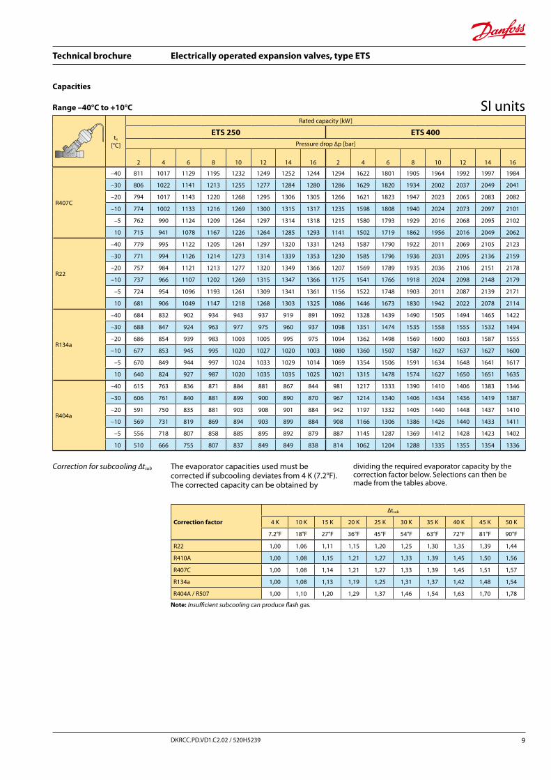
Correction for subcooling ∆tsub
Note: Insufficient subcooling can produce flash gas.
The evaporator capacities used must be corrected if subcooling deviates from 4 K (7.2°F).The corrected capacity can be obtained by
dividing the required evaporator capacity by the correction factor below. Selections can then be made from the tables above.
te
[°C]
Rated capacity [kW]
ETS 250 ETS 400Pressure drop ∆p [bar]
2 4 6 8 10 12 14 16 2 4 6 8 10 12 14 16
Correction factor
∆tsub
4 K 10 K 15 K 20 K 25 K 30 K 35 K 40 K 45 K 50 K
7.2°F 18°F 27°F 36°F 45°F 54°F 63°F 72°F 81°F 90°F
Capacities
Range –40°C to +10°C SI units
Technical brochure Electrically operated expansion valves, type ETS
10 DKRCC.PD.VD1.C2.02 / 520H5239
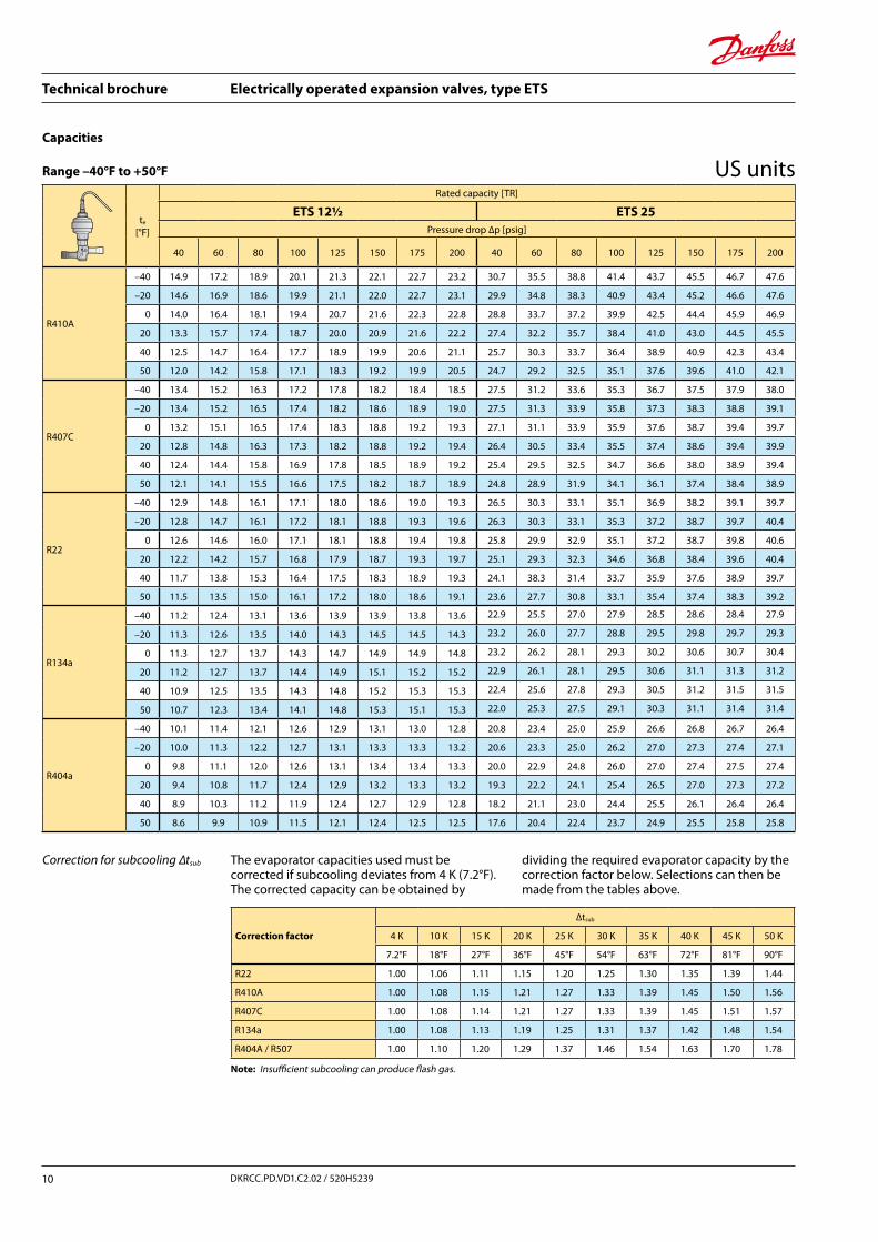
Correction for subcooling ∆tsub
Note: Insufficient subcooling can produce flash gas.
The evaporator capacities used must be corrected if subcooling deviates from 4 K (7.2°F).The corrected capacity can be obtained by
dividing the required evaporator capacity by the correction factor below. Selections can then be made from the tables above.
te
[°F]
Rated capacity [TR]
ETS 12½ ETS 25Pressure drop ∆p [psig]
40 60 80 100 125 150 175 200 40 60 80 100 125 150 175 200
R410A
–40 14.9 17.2 18.9 20.1 21.3 22.1 22.7 23.2 30.7 35.5 38.8 41.4 43.7 45.5 46.7 47.6
–20 14.6 16.9 18.6 19.9 21.1 22.0 22.7 23.1 29.9 34.8 38.3 40.9 43.4 45.2 46.6 47.6
0 14.0 16.4 18.1 19.4 20.7 21.6 22.3 22.8 28.8 33.7 37.2 39.9 42.5 44.4 45.9 46.9
20 13.3 15.7 17.4 18.7 20.0 20.9 21.6 22.2 27.4 32.2 35.7 38.4 41.0 43.0 44.5 45.5
40 12.5 14.7 16.4 17.7 18.9 19.9 20.6 21.1 25.7 30.3 33.7 36.4 38.9 40.9 42.3 43.4
50 12.0 14.2 15.8 17.1 18.3 19.2 19.9 20.5 24.7 29.2 32.5 35.1 37.6 39.6 41.0 42.1
R407C
–40 13.4 15.2 16.3 17.2 17.8 18.2 18.4 18.5 27.5 31.2 33.6 35.3 36.7 37.5 37.9 38.0
–20 13.4 15.2 16.5 17.4 18.2 18.6 18.9 19.0 27.5 31.3 33.9 35.8 37.3 38.3 38.8 39.1
0 13.2 15.1 16.5 17.4 18.3 18.8 19.2 19.3 27.1 31.1 33.9 35.9 37.6 38.7 39.4 39.7
20 12.8 14.8 16.3 17.3 18.2 18.8 19.2 19.4 26.4 30.5 33.4 35.5 37.4 38.6 39.4 39.9
40 12.4 14.4 15.8 16.9 17.8 18.5 18.9 19.2 25.4 29.5 32.5 34.7 36.6 38.0 38.9 39.4
50 12.1 14.1 15.5 16.6 17.5 18.2 18.7 18.9 24.8 28.9 31.9 34.1 36.1 37.4 38.4 38.9
R22
–40 12.9 14.8 16.1 17.1 18.0 18.6 19.0 19.3 26.5 30.3 33.1 35.1 36.9 38.2 39.1 39.7
–20 12.8 14.7 16.1 17.2 18.1 18.8 19.3 19.6 26.3 30.3 33.1 35.3 37.2 38.7 39.7 40.4
0 12.6 14.6 16.0 17.1 18.1 18.8 19.4 19.8 25.8 29.9 32.9 35.1 37.2 38.7 39.8 40.6
20 12.2 14.2 15.7 16.8 17.9 18.7 19.3 19.7 25.1 29.3 32.3 34.6 36.8 38.4 39.6 40.4
40 11.7 13.8 15.3 16.4 17.5 18.3 18.9 19.3 24.1 38.3 31.4 33.7 35.9 37.6 38.9 39.7
50 11.5 13.5 15.0 16.1 17.2 18.0 18.6 19.1 23.6 27.7 30.8 33.1 35.4 37.4 38.3 39.2
R134a
–40 11.2 12.4 13.1 13.6 13.9 13.9 13.8 13.6 22.9 25.5 27.0 27.9 28.5 28.6 28.4 27.9
–20 11.3 12.6 13.5 14.0 14.3 14.5 14.5 14.3 23.2 26.0 27.7 28.8 29.5 29.8 29.7 29.3
0 11.3 12.7 13.7 14.3 14.7 14.9 14.9 14.8 23.2 26.2 28.1 29.3 30.2 30.6 30.7 30.4
20 11.2 12.7 13.7 14.4 14.9 15.1 15.2 15.2 22.9 26.1 28.1 29.5 30.6 31.1 31.3 31.2
40 10.9 12.5 13.5 14.3 14.8 15.2 15.3 15.3 22.4 25.6 27.8 29.3 30.5 31.2 31.5 31.5
50 10.7 12.3 13.4 14.1 14.8 15.3 15.1 15.3 22.0 25.3 27.5 29.1 30.3 31.1 31.4 31.4
R404a
–40 10.1 11.4 12.1 12.6 12.9 13.1 13.0 12.8 20.8 23.4 25.0 25.9 26.6 26.8 26.7 26.4
–20 10.0 11.3 12.2 12.7 13.1 13.3 13.3 13.2 20.6 23.3 25.0 26.2 27.0 27.3 27.4 27.1
0 9.8 11.1 12.0 12.6 13.1 13.4 13.4 13.3 20.0 22.9 24.8 26.0 27.0 27.4 27.5 27.4
20 9.4 10.8 11.7 12.4 12.9 13.2 13.3 13.2 19.3 22.2 24.1 25.4 26.5 27.0 27.3 27.2
40 8.9 10.3 11.2 11.9 12.4 12.7 12.9 12.8 18.2 21.1 23.0 24.4 25.5 26.1 26.4 26.4
50 8.6 9.9 10.9 11.5 12.1 12.4 12.5 12.5 17.6 20.4 22.4 23.7 24.9 25.5 25.8 25.8
Correction factor
∆tsub
4 K 10 K 15 K 20 K 25 K 30 K 35 K 40 K 45 K 50 K
7.2°F 18°F 27°F 36°F 45°F 54°F 63°F 72°F 81°F 90°F
R22 1.00 1.06 1.11 1.15 1.20 1.25 1.30 1.35 1.39 1.44
R410A 1.00 1.08 1.15 1.21 1.27 1.33 1.39 1.45 1.50 1.56
R407C 1.00 1.08 1.14 1.21 1.27 1.33 1.39 1.45 1.51 1.57
R134a 1.00 1.08 1.13 1.19 1.25 1.31 1.37 1.42 1.48 1.54
R404A / R507 1.00 1.10 1.20 1.29 1.37 1.46 1.54 1.63 1.70 1.78
Capacities
Range –40°F to +50°F US units
Technical brochure Electrically operated expansion valves, type ETS
11DKRCC.PD.VD1.C2.02 / 520H5239
R410A
–40 55,9 64,6 70,8 75,4 79,7 82,9 85,2 86,8 104,2 120,3 131,8 140,4 148,5 154,4 158,6 161,6
–20 54,6 63,4 69,8 74,6 79,1 82,5 85,0 86,7 101,6 118,0 129,9 138,9 147,4 153,6 158,2 161,5
0 52,6 61,4 67,9 72,8 77,5 81,0 83,6 85,5 97,8 114,3 126,4 135,6 144,3 150,9 155,7 159,2
20 49,9 58,7 65,1 70,1 74,8 78,4 81,1 83,1 93,0 109,2 121,2 130,4 139,3 146,0 151,0 154,6
40 46,8 55,2 61,4 66,3 71,0 74,6 77,2 79,2 87,1 102,7 114,4 123,5 132,2 138,8 143,8 147,5
50 45,0 53,2 59,3 64,1 68,7 72,2 74,8 76,8 83,8 99,0 110,4 119,3 127,8 134,4 139,3 142,9
R407C
–40 50,4 57,3 61,9 65,1 67,9 69,6 70,6 71,0 93,9 106,6 115,2 121,2 126,4 129,6 131,5 132,2
–20 50,4 57,6 62,5 66,0 69,1 71,1 72,4 73,0 93,8 107,2 116,4 122,9 128,7 132,4 134,7 135,9
0 49,7 57,2 62,5 66,3 69,6 71,9 73,4 74,2 92,6 106,6 116,3 123,4 129,6 133,9 136,6 138,2
20 48,5 56,2 61,7 65,7 69,3 71,8 73,5 74,6 90,4 104,7 114,9 122,3 129,1 133,8 136,9 138,8
40 46,8 54,6 60,1 64,3 68,1 70,8 72,7 73,9 87,1 101,6 111,9 119,7 126,8 131,8 135,3 137,5
50 45,7 53,5 59,0 63,2 67,1 69,9 71,8 73,1 85,2 99,5 109,9 117,7 125,0 130,1 133,7 136,1
R22
–40 48,5 55,6 60,6 64,3 67,7 70,1 71,8 72,9 90,3 103,6 112,9 119,8 126,1 130,5 133,7 135,7
–20 48,1 55,5 60,8 64,7 68,3 70,9 72,8 74,0 89,6 103,4 113,1 120,4 127,2 132,0 135,5 137,8
0 47,3 54,9 60,3 64,4 68,2 71,0 73,1 74,5 88,1 102,2 112,3 119,9 127,1 132,3 136,0 138,7
20 46,0 53,6 59,2 63,5 67,5 70,4 72,6 74,1 85,6 99,9 110,3 118,1 125,6 131,1 135,1 138,0
40 44,2 51,9 57,5 61,8 65,9 68,9 71,2 72,9 82,3 96,6 107,0 115,0 122,7 128,4 132,6 135,7
50 43,2 50,8 56,4 60,7 64,8 67,9 70,2 71,9 80,4 94,5 104,9 112,9 120,6 126,4 130,7 133,8
R134a
–40 41,8 46,4 49,2 50,9 51,9 52,2 51,8 50,9 77,7 86,4 91,6 94,7 96,7 97,1 96,4 94,8
–20 42,3 47,3 50,4 52,4 53,8 54,2 54,1 53,4 78,7 88,1 93,9 97,6 100,1 101,0 100,7 99,5
0 42,3 47,7 51,1 53,4 55,1 55,8 55,9 55,5 78,7 88,8 95,2 99,4 102,5 103,9 104,1 103,3
20 41,8 47,5 51,3 53,8 55,7 56,7 57,0 56,8 77,8 88,5 95,4 100,1 103,7 105,6 106,2 105,8
40 40,8 46,7 50,7 53,4 55,6 56,9 57,4 57,4 75,9 87,0 94,4 99,5 103,6 105,9 106,9 106,8
50 40,1 46,1 50,1 53,0 55,3 56,6 57,2 57,3 74,6 85,8 93,4 98,6 102,9 105,4 106,6 106,7
R404a
–40 37,9 42,6 45,6 47,4 48,6 49,0 48,9 48,2 70,6 79,4 84,8 88,2 90,5 91,3 91,0 89,8
–20 37,5 42,5 45,7 47,8 49,3 50,0 50,0 49,6 69,9 79,2 85,1 89,0 91,8 93,0 93,1 92,3
0 36,6 41,8 45,2 47,5 49,2 50,1 50,4 50,1 68,1 77,8 84,2 88,4 91,7 93,3 93,8 93,3
20 35,2 40,5 44,0 46,4 48,4 49,4 49,8 49,7 65,5 75,3 81,9 86,4 90,1 92,0 92,8 92,6
40 33,3 38,5 42,1 44,6 46,6 47,8 48,3 48,3 62,0 71,7 78,4 83,0 86,8 89,0 90,0 89,9
50 32,2 37,3 40,9 43,4 45,4 46,6 47,2 47,2 59,9 69,5 76,1 80,7 84,6 86,8 87,8 87,8
R22 1,00 1,06 1,11 1,15 1,20 1,25 1,30 1,35 1,39 1,44
R410A 1,00 1,08 1,15 1,21 1,27 1,33 1,39 1,45 1,50 1,56
R407C 1,00 1,08 1,14 1,21 1,27 1,33 1,39 1,45 1,51 1,57
R134a 1,00 1,08 1,13 1,19 1,25 1,31 1,37 1,42 1,48 1,54
R404A / R507 1,00 1,10 1,20 1,29 1,37 1,46 1,54 1,63 1,70 1,78
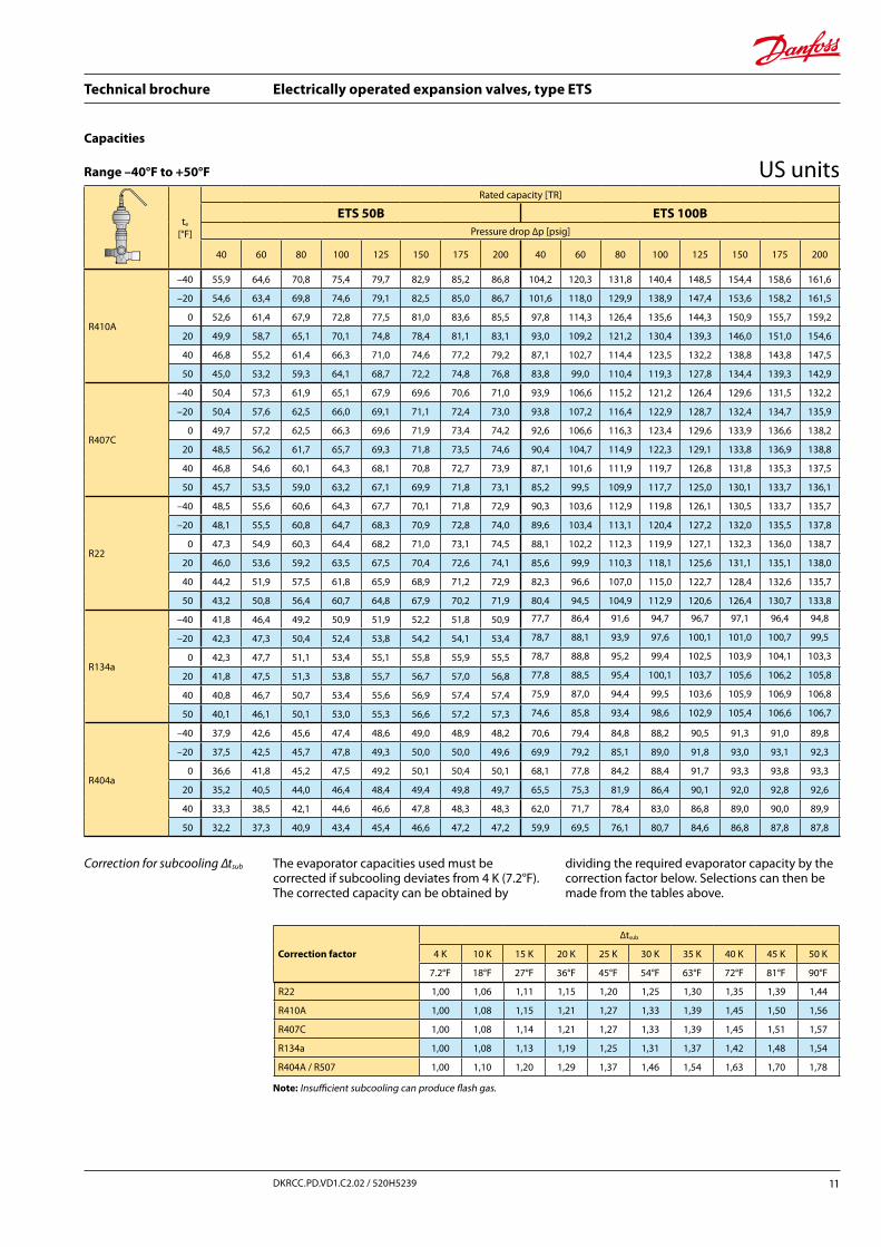
Correction for subcooling ∆tsub
Note: Insufficient subcooling can produce flash gas.
The evaporator capacities used must be corrected if subcooling deviates from 4 K (7.2°F).The corrected capacity can be obtained by
dividing the required evaporator capacity by the correction factor below. Selections can then be made from the tables above.
te
[°F]
Rated capacity [TR]
ETS 50B ETS 100BPressure drop ∆p [psig]
40 60 80 100 125 150 175 200 40 60 80 100 125 150 175 200
Correction factor
∆tsub
4 K 10 K 15 K 20 K 25 K 30 K 35 K 40 K 45 K 50 K
7.2°F 18°F 27°F 36°F 45°F 54°F 63°F 72°F 81°F 90°F
Capacities
Range –40°F to +50°F US units
Technical brochure Electrically operated expansion valves, type ETS
12 DKRCC.PD.VD1.C2.02 / 520H5239
R22 1,00 1,06 1,11 1,15 1,20 1,25 1,30 1,35 1,39 1,44
R410A 1,00 1,08 1,15 1,21 1,27 1,33 1,39 1,45 1,50 1,56
R407C 1,00 1,08 1,14 1,21 1,27 1,33 1,39 1,45 1,51 1,57
R134a 1,00 1,08 1,13 1,19 1,25 1,31 1,37 1,42 1,48 1,54
R404A / R507 1,00 1,10 1,20 1,29 1,37 1,46 1,54 1,63 1,70 1,78
R407C
–40 258 292 315 331 344 351 355 356 411 466 502 527 548 561 567 568
–20 257 293 318 335 350 359 364 366 410 468 507 535 558 573 581 584
0 254 292 317 336 352 363 369 372 405 465 506 536 562 579 589 594
20 247 286 313 333 350 362 369 374 395 456 499 531 559 577 589 596
40 238 277 305 325 343 356 364 369 380 442 486 518 548 568 581 589
50 232 271 299 319 338 351 360 365 371 432 476 509 539 560 574 582
R22
–40 250 286 312 331 348 361 369 375 398 456 497 528 556 575 589 598
–20 248 286 313 333 351 365 374 381 395 455 499 531 560 582 597 607
0 243 282 310 331 351 365 376 383 388 450 495 528 560 583 599 611
20 236 276 305 326 347 362 373 381 377 440 486 521 553 578 595 608
40 227 267 296 318 339 355 366 375 363 425 471 507 540 566 584 598
50 222 261 290 312 333 349 361 370 354 416 462 498 531 557 576 590
R134a
–40 215 239 253 262 267 268 266 262 342 381 404 417 426 428 425 418
–20 217 243 259 269 276 279 278 275 347 388 414 430 441 445 444 439
0 217 245 263 275 283 287 288 285 347 391 420 438 452 458 459 455
20 215 244 264 276 286 292 293 292 343 390 420 441 457 465 468 466
40 210 240 261 275 286 292 295 295 334 383 416 438 456 466 471 470
50 206 237 258 272 284 291 294 295 329 378 411 434 453 464 469 470
R404a
–40 195 219 234 243 249 252 251 247 311 349 373 388 398 401 400 394
–20 193 218 235 245 253 256 256 254 307 348 374 391 403 409 409 405
0 188 215 232 244 253 257 258 257 300 342 370 389 403 410 412 410
20 181 208 226 238 248 253 256 255 288 331 360 380 396 404 408 406
40 171 198 216 229 239 245 248 247 273 315 344 365 381 391 395 395
50 165 192 210 222 233 239 242 242 263 306 334 355 371 381 385 385
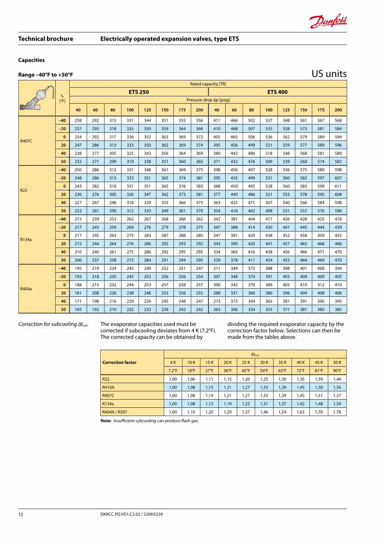
Correction for subcooling ∆tsub
Note: Insufficient subcooling can produce flash gas.
The evaporator capacities used must be corrected if subcooling deviates from 4 K (7.2°F).The corrected capacity can be obtained by
dividing the required evaporator capacity by the correction factor below. Selections can then be made from the tables above.
te
[°F]
Rated capacity [TR]
ETS 250 ETS 400Pressure drop ∆p [psig]
40 60 80 100 125 150 175 200 40 60 80 100 125 150 175 200
Correction factor
∆tsub
4 K 10 K 15 K 20 K 25 K 30 K 35 K 40 K 45 K 50 K
7.2°F 18°F 27°F 36°F 45°F 54°F 63°F 72°F 81°F 90°F
Capacities
Range –40°F to +50°F US units
Technical brochure Electrically operated expansion valves, type ETS
13DKRCC.PD.VD1.C2.02 / 520H5239
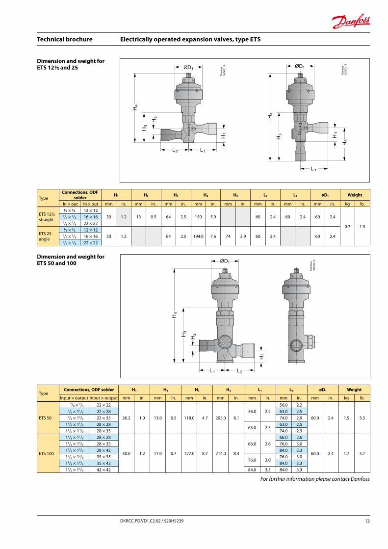
ETS 50
7/8 × 7/8 22 × 22
26.2 1.0 13.0 0.5 118.0 4.7 205.0 8.156.0 2.2
56.0 2.2
60.0 2.4 1.5 3.3
7/8 × 11/8 22 × 28 63.0 2.57/8 × 13/8 22 × 35 74.0 2.9
11/8 × 11/8 28 × 2863.0 2.5
63.0 2.511/8 × 13/8 28 × 35 74.0 2.9
ETS 100
11/8 × 11/8 28 × 28
30.0 1.2 17.0 0.7 127.0 8.7 214.0 8.4
66.0 2.666.0 2.6
60.0 2.4 1.7 3.7
11/8 × 13/8 28 × 35 76.0 3.011/8 × 15/8 28 × 42 84.0 3.313/8 × 13/8 35 × 35
76.0 3.076.0 3.0
13/8 × 15/8 35 × 42 84.0 3.315/8 × 15/8 42 × 42 84.0 3.3 84.0 3.3
Dimension and weight for ETS 50 and 100
TypeConnections, ODF solder H1 H2 H3 H4 L1 L2 øD1 Weight
Input × output Input × output mm in. mm in. mm in. mm in. mm in. mm in. mm in. kg lb.
Dimension and weight for ETS 12½ and 25
TypeConnections, ODF
solder H1 H2 H3 H4 H5 L1 L2 øD1 Weight
In × out In × out mm in. mm in. mm in. mm in. mm in. mm in. mm in. mm in. kg lb.
ETS 12½straight
½ × ½ 12 × 1230 1.2 13 0.5 64 2.5 150 5.9 60 2.4 60 2.4 60 2.4
0.7 1.5
5/8 × 5/8 16 × 167/8 × 7/8 22 × 22
ETS 25angle
½ × ½ 12 × 1230 1.2 64 2.5 194.0 7.6 74 2.9 60 2.4 60 2.45/8 × 5/8 16 × 16
7/8 × 7/8 22 × 22
For further information please contact Danfoss
Danfoss A/S (AC-SMC / sw/bpv) 05 - 2011
Technical brochure Electrically operated expansion valves, type ETS
14 DKRCC.PD.VD1.C2.02 / 520H5239
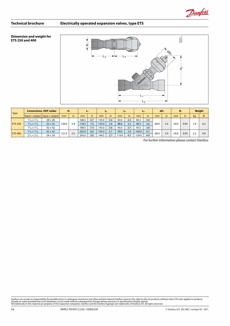
ETS 250 11/8 × 11/8 28 × 28
120.0 5.4168.5 6.7 143.0 5.6 83.0 3.3 85.5 3.4
60.0 2.4 24.0 0.95 1.9 4.213/8 × 13/8 35 × 35 178.5 7.0 143.0 5.6 88.0 3.5 90.5 3.615/8 × 15/8 42 × 42 188.5 7.4 143.0 5.6 93.0 3.7 95.5 3.8
ETS 40015/8 × 15/8 42 × 42
121.0 5.5203.0 8.0 144.5 5,7 99.0 3.9 104.0 4.1
60.0 2.4 24.0 0.95 2.2 4.921/8 × 21/8 54 × 54 243.0 9.6 144.5 5.7 119.0 4.7 124.0 4.9
TypeConnections, ODF solder H1 L1 L2 L3 L4 øD1 B1 Weight
Input × output Input × output mm in mm in mm in mm in mm in mm in mm in kg lb
For further information please contact Danfoss
Dimension and weight for ETS 250 and 400