technical bulletin 2/14 satellar and vlan smart 1. overview to virtual local area...
TRANSCRIPT

1
SMART
RADIO
VLAN
Virtual Local Area Networking is a
technology specified in IEEE 802.1Q
standard. VLAN can be used to
separate physical LAN to multiple
virtual LANs and thus differentiate
and control the access of devices
connected physically to the same
network. The following figure
illustrates the separation of the
physical LAN.
PHYSICAL LAN
Physical LAN is a network consisting
of L2 devices such as switches and
hubs. On the edges of the physical
LAN are the host devices, such as
PLCs, management computers and
routers. SATELLAR radio modem
functions as a router.
BROADCAST DOMAIN
Boundaries for a LAN can also be
defined by the reach of the
broadcasts sent to the network. An
example of such broadcast is the ARP
(Address Resolution Protocol) request,
which is used by the Ethernet
protocol to find the MAC address of
the specific IP destination address.
1
Switch will copy the received broadcast
message to all of its ports.
Broadcast
Broadcast
Switch
VLAN B:
data network
VLAN A:
monitoring
network
physical LAN
host
router
host
SATELLAR AND VLAN
1. OVERVIEW TO VIRTUAL LOCAL AREA NETWORKING
Technical Bulletin 2/14
August 2014

2
VLAN TAG
According to the standard IEEE
802.1Q, Ethernet frame is extended
with an optional VLAN Tag, which
uniquely defines the LAN. This tag is
used to differentiate Ethernet frame
processing. The Ethernet protocol is
a link layer protocol (Layer 2, L2).
Switches are the network devices that
provide the forwarding functionality
for L2. Therefore, the VLAN
configuration and accordingly the
network separation in the network is
applied by switch configuration.
VLAN Tag
2
SWITCH CONFIGURATION FOR VLAN
For each Ethernet network, it is the
switch configuration that defines how
the physical LAN has been separated
to different VLANs. Switch ports are
assigned to one or more separate
VLANs. Switches only forward traffic
between ports belonging to the same
VLAN. Switch ports can also be set to
operate without any VLAN
configuration. Depending on the
switch vendor and model, the VLAN
configuration in the switch port can
be set to allow certain VLAN tags and
add or modify the IDs in the tags of
ingress or egress ethernet frames.
Expect
VLAN 101, 7
Expect
VLAN 7
Expect VLAN 7,
remove/add tags.
Expect
VLAN 101
Expect
VLAN 101
Expect
VLAN 101,
remove/add
tags.
No need for VLAN
configuration at
host: switch does
the tagging.
Expect
VLAN 101, 7
VLAN 101
VLAN SEPARATION
With VLAN tagging to ethernet
frames and proper switch port
configuration, the physical network
has now been separated to two
individual virtual networks, VLANs.
VLAN 7
3 3
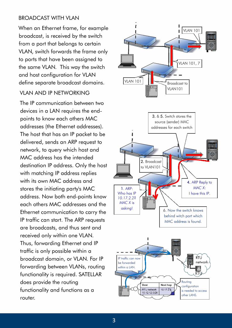
BROADCAST WITH VLAN
When an Ethernet frame, for example
broadcast, is received by the switch
from a port that belongs to certain
VLAN, switch forwards the frame only
to ports that have been assigned to
the same VLAN. This way the switch
and host configuration for VLAN
define separate broadcast domains.
VLAN 101, 7
VLAN 101
VLAN 101 Broadcast to
VLAN101
VLAN AND IP NETWORKING
The IP communication between two
devices in a LAN requires the end-
points to know each others MAC
addresses (the Ethernet addresses).
The host that has an IP packet to be
delivered, sends an ARP request to
network, to query which host and
MAC address has the intended
destination IP address. Only the host
with matching IP address replies
with its own MAC address and
stores the initiating party's MAC
address. Now both end-points know
each others MAC addresses and the
Ethernet communication to carry the
IP traffic can start. The ARP requests
are broadcasts, and thus sent and
received only within one VLAN.
Thus, forwarding Ethernet and IP
traffic is only possible within a
broadcast domain, or VLAN. For IP
forwarding between VLANs, routing
functionality is required. SATELLAR
does provide the routing
functionality and functions as a
router.
2. Broadcast
to VLAN101
1. ARP:
Who has IP
10.17.2.2? MAC X is
asking!
4. ARP Reply to
MAC X:
I have this IP.
3. & 5. Switch stores the
source (sender) MAC
addresses for each switch
6. Now the switch knows
behind witch port which
MAC address is found.
IP traffic can now
be forwarded
within a LAN.
Routing
configuration
is needed to access
other LANS.

4 4
SMART
RADIO
SATELLAR AND VLAN
2. VIRTUAL LOCAL AREA NETWORKING USE CASE EXAMPLE
Technical Bulletin 2/14
August 2014
SATELLAR VLAN SUPPORT
Target network may already have a
extensive VLAN configuration applied
in the switches. SATELLAR support for
VLAN allows easy integration to pre-
configured networks. Because
SATELLAR is a router on the edge of
the broadcast domain, VLANs are not
extended to or over the radio
interface. SATELLAR is configured to
VLAN by setting up a new virtual
interface with the desired VLAN ID
and IP address. SATELLAR will accept
or initiate communication with these IP
addresses only with matching ethernet
VLAN tag. All VLAN interfaces share
the same physical ethernet interface.
Virtual
Interfaces
Physical
Interface
Data
Management
DATA AND MANAGEMENT SEPARATION
Typical usage scenario for VLANs is to separate data network and management
network by assigning them to different VLANs. In many cases, the automation
networks already have this kind of separation applied by their switch
configuration.
VLAN operation does not
extend over the radio interface.

5 5
ENABLING VLAN OPERATION
Configuration parameters for VLAN
operation are available under
Routing tab, in VLAN application.
Create new VLAN interface by
providing the IP address (step 1),
name (2) and the VLAN id (3), and
then select Add New VLAN Interface
(4). This creates an entry to the VLAN
listing. The VLANs listed in the table
are enabled when VLAN state
parameter is switched to ON (5). All
configurations are taken into use by
selecting Commit Changes (step 6).
6 Finalize VLAN
configuration by selecting
Commit Changes.
4
1
2
3
SMART
RADIO
SATELLAR AND VLAN
3. CONFIGURING VLAN IN SATELLAR
Technical Bulletin 2/14
August 2014
VLAN PARAMETERS
VLAN state
Turns the VLAN functionality on or off.
IP address with mask
Defines the IP address and the
network for the created VLAN
interface.
VLAN Name
Description or name for the VLAN for
the user identification.
VLAN ID
Uniquely identifies the VLAN. The ID
to expect on incoming frames and
add to outgoing frames. Value
between 0-4096.
Proxy ARP
Set the Proxy ARP on/off for the
specific VLAN interface.
5 To enable or disable
VLAN functionality:
select ON or OFF.