technical catalogue line protection devices miniature
TRANSCRIPT

Technical catalogue
Line Protection DevicesMiniature circuit-breakers (MCB)r S200
아래 제품을 대체 합니다.

MCBs protect installations against overload and short-circuit, warranting reliability and safety for operations.
New System pro M compact S200 series satisfies most common requirements in terms of MCBs, allowing the usage of them for domestic, industrial and commercial applications.
Two series - S200 and S200M - with two different breaking capacities up to 10kA are available, in all characteristics (B, C, D, K and Z) and configurations (1P, 1P+N, 2P, 3P, 3P+N, 4P) in all the sizes up to 63A.
All these MCBs comply to IEC/EN60898 and IEC/EN60947-2.
It is available a great number of auxiliary components and accessories that make installation in switchboards and consumer units practical and economic. It is also available the new integrated auxiliary contact on the bottom side which permits to save 50% space.
IntroductionMCB - S200
S200 series devices obtained a lot of marks a n d a p p ro v a l s , s o they can be used in all world's markets.
Intr
od
uctio
n
1 S200

S200 - the details make the differenceA range designed to ensure efficiency and protection
Save your time –all important dataavailable rightaway.
Easy product name, easy identification, easy life.
Contact position indicator (CPI) - shows the correct position of the contact.
Twin terminal forseparate feedingof busbar andconductor
Captive screws :don’t loose what’simportant for you.
IPXXB - finger safety.
Easy identificationof the product andhighly resistantlaser marking.
Quick identificationthanks to laserprinted EANmarking.
Whatever yourapplication needis – applicable witha wide range ofaccessories.
Intr
od
uctio
n
IntroductionMCB - S200
2S200

Introduction
MCB - S200
3
Intr
od
ucti
on Contact position indicationᵅCPIᵆ
All System pro M compact® MCBs
are suited with a contact position
indication (CPI) on the toggle and on
the top of the surface. You can easily
identify, if the MCB is in the ON or the
OFF position – easy and safe
maintenance work is possible.
Laser printing
All printings of the S200 and S200M
MCBs, like the approvals on the dome
and the product identification, are
printed by a laser. The laser printing
ensures a friction, scratch and solvent
resistant marking on the MCBs.
Easy identification of the products in
case of maintenance or replacements
due to safe laser printing.
Approvals printed on the dome
S200 and S200M MCBs comply to
IEC/EN 60898 and IEC/EN 60947 and
carry all relevant approval marks for
each market and segment they are
destined to. The certification markings
are also printed on the dome of the
MCB. Thus make it possible to see the
markings also in the mounted position.
For control and acceptance
procedure – certification marks
visible on fitted devices on the dome.
Removal of the devices
Special quick fastening for an easy
removal of the devices from the
assembly pressing upwards, both
for S200 and S200M.
Housing material
By using the state-of-the-art housing
material, ABB is taking care of the
environment. With the latest generation
of thermoplastics. It’s possible to recycle
the MCBs – especially the thermoplastic
housing-material can be re-used. By using
the latest generation of thermoplastics
the material stability of all System pro M
compact® MCBs is improved.
S200 and S200M are 100% free of
halogens – no environmental
pollution.
IPXXB - finger safe terminals
The System pro M compact® MCB’sare equiped with 35 mm² + 10 mm²
cylinder lift twin terminals, a well proven
and reliable technology - designed for
sophisticated industrial use.
The cross wiring can easily be done by
inserting the System pro M compact®
busbars into the rear terminal part and
then the incoming wires into the front
part of the terminal.
S200

IntroductionMCB - S200
4
Intr
od
uctio
n
Trip
ping
tim
e
Min
utes
Sec
onds
Multiple of rated current
Tripping characteristic B, C, D
Tripping diagramsTripping characteristic K, Z
acc. to IEC/EN 60898-1In = 0.5...63AS200 / S200M
acc. to IEC/EN 60947-2 In = 0.5...63AS200 / S200M
Tripping characteristics
Acc. to Tripping characteristicand rated current
Thermal release Electromagnetic release
Current Tripping time Currents Tripping time
conventionalnon-tripping C
conventionaltripping C
holdcurrentsurges
tripat least at
IEC/EN 60898-1 B 6 to 63 A 1.13 · In1.45 · In
> 1 h< 1 h
3 · In5 · In
> 0.1 s< 0.1 s
C 0.5 to 63 A 1.13 · In1.45 · In
> 1 h< 1 h
5 · In10 · In
> 0.1 s< 0.1 s
D 0.5 to 63 A 1.13 · In1.45 · In
> 1 h< 1 h
10 · In20 · In
> 0.1 s< 0.1 s
IEC/EN 60947-2 K 0.5 to 63 A 1.05 · In1.2 · In
> 1 h< 1 h not applicable
1.05 · In1.2 · In
> 2 h< 1 h
10 · In14 · In
> 0.2 s< 0.2 s
IEC/EN 60947-2 Z 0.5 to 63 A 1.05 · In1.2 · In
> 1 h< 1 h not applicable
1.05 · In1.2 · In
> 2 h< 1 h
2 · In3 · In
> 0.2 s< 0.2 s
The tripping for the electromagnetic trips are valid for AC 50 ... 60 Hz. For other frequencies please see table below.
The thermal releases are calibrated to a nominal reference ambient temperature; for Z and K, the value is 20ą, for B and C = 30ą. In the case of higher ambient temperatures, the current values fall by ca. 6 % for each 10 K temperature rise.
As from operating temperature (after I1 > 1 h or, as applicable, 2 h).
Sec
onds
Min
utes
Trip
ping
tim
e
Multiple of rated current
AC DC100 Hz 200 Hz 400 Hz
Factor approx. 1.1 1.2 1.5 1.5
S200

S200 [ ABB ] GCP [ HONEYWELL ] C60N [ SCHNEIDER ]
RATED VOLTAGE
AMPERE RATING [ A ]
NO OF POLES
RATED BREAK AMPERE
PROTECTION MODE
INTERNAL CIRCUIT
COMBINATION WITH AUX. ELEMENTS
AMBIENT TEMP. / HUMIDITY
REFERENCE AMBIENT TEMP.
DIELECTRIC STRENGTH
MOUNTING / CONNECTION
ELECTRICAL LIFE
APPROVALS
230 ~ 240VAC(1pole)400 ~ 415VAC(2,3,4pole)
DC60V(1pole)DC125V(2,3,4pole)
AC250V(50/60 Hz)DC60V(1pole only)DC120V(2pole only)
230 ~ 240VAC(1pole)400 ~ 415VAC(2,3,4pole)
0.5 ~ 63A 0.1 ~ 30A 1 ~ 63A
1, 2, 3, 4 pole1P + 1N3P + 1N
1, 2, 3 pole only 1, 2, 3, 4 pole only
133VAC(1P) & 230VAC(2,3,4P) : 20KA
230VAC(1P) & 400VAC(2,3,4P) : 10KA
60VDC(1P) & 125VDC(2,3,4P) : 10KA
AC250V : 2.5KADC60V : 2.5KA(1pole)DC120V : 2.5KA(2pole)
133VAC(1P) & 230VAC(2,3,4P) : 20KA
230VAC(1P) & 400VAC(2,3,4P) : 10KA
B, C, D, K, ZInstantaneous (I)Medium Speed (M)
type availableC, D
Series trip (S)Auxiliary switch (Ax)
Auxiliary contactSignal contact
Shunt tripUndervoltage release
Motor Operating Device
-25 ~ +55°C 10 to 60 degrees by Celsius0 to 85% by Relative Humidity
-40 ~ +80°C
B, C, D : 30°CK, Z : 20°C
40°C -30 ~ +70°C
1 Minute at AC2000V(50/60Hz)
1 Minute at AC1500V(50/60Hz)
On DIN rail 35 mm acc. to EN 60715 by fast clip
Failsafe bi-directional cylinder-lift terminal (No. 2 Pozidrive)
Panel & Integral typeScrew-in (Din rail)
Clip on DIN rail 35mmUpstream or downstream
6,000 ops (AC), 6,000 ops. (DC)1 cycle (1s - ON, 9s - OFF)
10,000 operations minimum(6,000 operations with rated ampere at 6
operations/min)
10,000 cycles (Electrical)20,000 cycles (Mechanical)
IEC/EN 60898-1, IEC/EN 60947-2, GB10963.1,
GB14048.2, UL 1077, CSA 22.2 No. 235
CE IEC/EN 60947-2
Technical specifications
MCB - S200Technical Data

7
Ap
plic
atio
n
Application
MCB - S200
Internal resistances and power losses of the Miniature Circuit-BreakersInternal resistances are subject to application-specific and environment-specific conditions and are therefore to be considered as
typical values.
Rated current In A
S200, S200M ( B, C, D ) S200, S200M ( K ) S200, S200M ( Z )
m� W m� W m� W
0.511.6
55001440630
1.41.41.6
63401550695
1.61.61.8
1010022701100
2.52.32.8
234
460150110
1.81.31.8
460165120
1.91.52.0
619202149
2.51.82.4
6810
551513.3
2.01.01.3
523812.6
1.92.51.26
10453.917.5
3.73.451.7
131620
13.37.06.25
2.31.82.5
12.67.76.7
1.262.02.7
–10.96.0
–2.82.4
253240
5.03.63.0
3.23.74.8
4.63.52.8
2.93.64.5
4.12.82.5
2.62.94.1
5063
1.31.2
3.254.8
1.250.7
2.95.2
1.81.3
4.45.2
Current intensities 0.5 – 4 not apply to B-type trip characteristic.
Influence of ambient temperatureThe thermal trips are calibrated for an ambient temerpature 30ąᵅfor B -, C - and D - characteristicᵆ and 20ąᵅfor K and Zᵆ.In the case of temperatures deviating from these values the tripping values:- are reduced in case of higher temperatures- are increased in case of lower temperatures
The electromagnetic trip is not dependent on temperature
Influence of adjacent devices S200
Correction factor FmNo. of adjacent devices Fm1 1
2 0.95
3 0.9
4 0.86
5 0.82
6 0.795
7 0.78
8 0.77
9 0.76
> 9 0.76
Fm F
acto
r
Number of devices
12 34 56 78 90.6
0.7
0.8
0.9
1.0
Example: S202 C16 with T=40ą
Type of use Values to use Formula Calculation Result
Continuous load In (amb. t°) - see tables - - In=15.1 A
Continuous load with 8 adj. devices In (amb. t°) - see tables, Fm (0.77) In (amb. t°)x0.77 15.1x0.77 In=11.63 A
S200
8
Ap
plic
atio
n
ApplicationMCB - S200
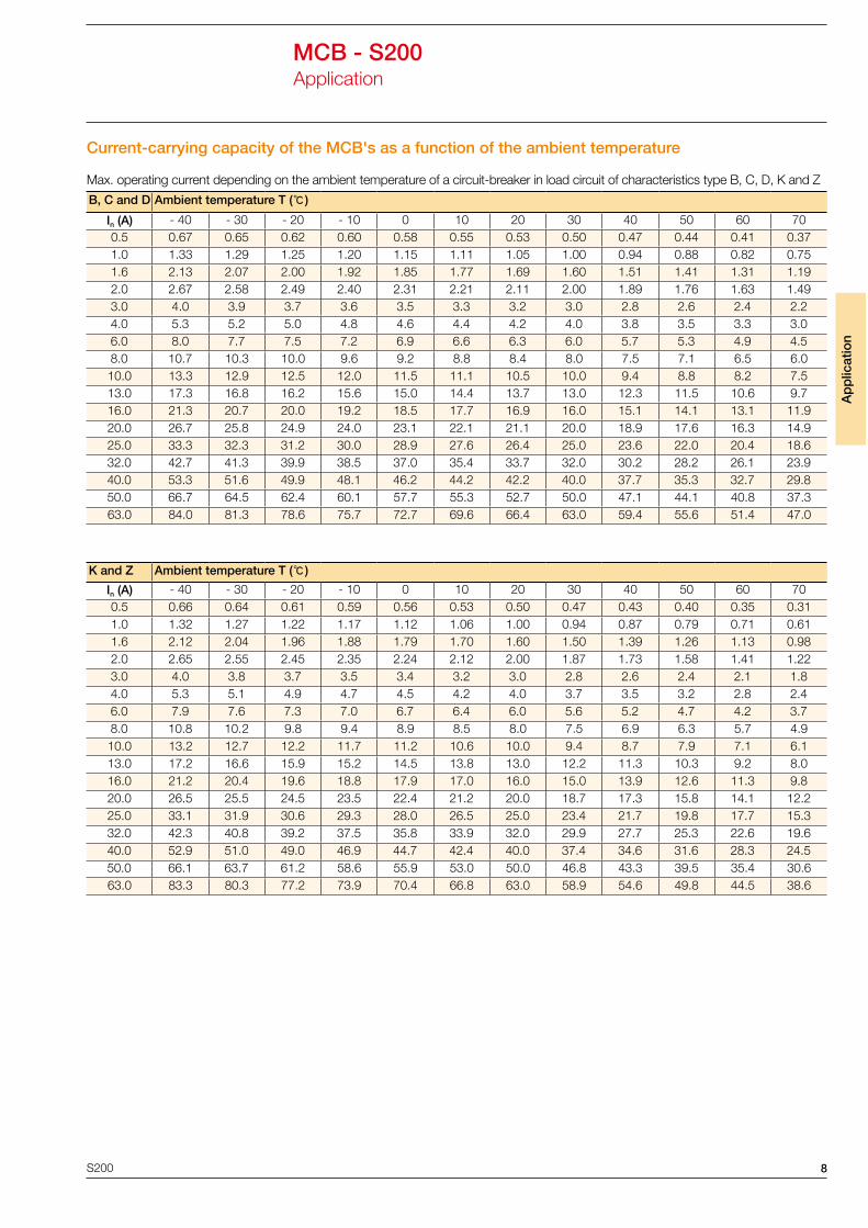
Max. operating current depending on the ambient temperature of a circuit-breaker in load circuit of characteristics type B, C, D, K and Z
B, C and D Ambient temperature T (ą)
In (A) - 40 - 30 - 20 - 10 0 10 20 30 40 50 60 700.5 0.67 0.65 0.62 0.60 0.58 0.55 0.53 0.50 0.47 0.44 0.41 0.371.0 1.33 1.29 1.25 1.20 1.15 1.11 1.05 1.00 0.94 0.88 0.82 0.751.6 2.13 2.07 2.00 1.92 1.85 1.77 1.69 1.60 1.51 1.41 1.31 1.192.0 2.67 2.58 2.49 2.40 2.31 2.21 2.11 2.00 1.89 1.76 1.63 1.493.0 4.0 3.9 3.7 3.6 3.5 3.3 3.2 3.0 2.8 2.6 2.4 2.24.0 5.3 5.2 5.0 4.8 4.6 4.4 4.2 4.0 3.8 3.5 3.3 3.06.0 8.0 7.7 7.5 7.2 6.9 6.6 6.3 6.0 5.7 5.3 4.9 4.58.0 10.7 10.3 10.0 9.6 9.2 8.8 8.4 8.0 7.5 7.1 6.5 6.010.0 13.3 12.9 12.5 12.0 11.5 11.1 10.5 10.0 9.4 8.8 8.2 7.513.0 17.3 16.8 16.2 15.6 15.0 14.4 13.7 13.0 12.3 11.5 10.6 9.716.0 21.3 20.7 20.0 19.2 18.5 17.7 16.9 16.0 15.1 14.1 13.1 11.920.0 26.7 25.8 24.9 24.0 23.1 22.1 21.1 20.0 18.9 17.6 16.3 14.925.0 33.3 32.3 31.2 30.0 28.9 27.6 26.4 25.0 23.6 22.0 20.4 18.632.0 42.7 41.3 39.9 38.5 37.0 35.4 33.7 32.0 30.2 28.2 26.1 23.940.0 53.3 51.6 49.9 48.1 46.2 44.2 42.2 40.0 37.7 35.3 32.7 29.850.0 66.7 64.5 62.4 60.1 57.7 55.3 52.7 50.0 47.1 44.1 40.8 37.363.0 84.0 81.3 78.6 75.7 72.7 69.6 66.4 63.0 59.4 55.6 51.4 47.0
K and Z Ambient temperature T (ą)
In (A) - 40 - 30 - 20 - 10 0 10 20 30 40 50 60 700.5 0.66 0.64 0.61 0.59 0.56 0.53 0.50 0.47 0.43 0.40 0.35 0.311.0 1.32 1.27 1.22 1.17 1.12 1.06 1.00 0.94 0.87 0.79 0.71 0.611.6 2.12 2.04 1.96 1.88 1.79 1.70 1.60 1.50 1.39 1.26 1.13 0.982.0 2.65 2.55 2.45 2.35 2.24 2.12 2.00 1.87 1.73 1.58 1.41 1.223.0 4.0 3.8 3.7 3.5 3.4 3.2 3.0 2.8 2.6 2.4 2.1 1.84.0 5.3 5.1 4.9 4.7 4.5 4.2 4.0 3.7 3.5 3.2 2.8 2.46.0 7.9 7.6 7.3 7.0 6.7 6.4 6.0 5.6 5.2 4.7 4.2 3.78.0 10.8 10.2 9.8 9.4 8.9 8.5 8.0 7.5 6.9 6.3 5.7 4.910.0 13.2 12.7 12.2 11.7 11.2 10.6 10.0 9.4 8.7 7.9 7.1 6.113.0 17.2 16.6 15.9 15.2 14.5 13.8 13.0 12.2 11.3 10.3 9.2 8.016.0 21.2 20.4 19.6 18.8 17.9 17.0 16.0 15.0 13.9 12.6 11.3 9.820.0 26.5 25.5 24.5 23.5 22.4 21.2 20.0 18.7 17.3 15.8 14.1 12.225.0 33.1 31.9 30.6 29.3 28.0 26.5 25.0 23.4 21.7 19.8 17.7 15.332.0 42.3 40.8 39.2 37.5 35.8 33.9 32.0 29.9 27.7 25.3 22.6 19.640.0 52.9 51.0 49.0 46.9 44.7 42.4 40.0 37.4 34.6 31.6 28.3 24.550.0 66.1 63.7 61.2 58.6 55.9 53.0 50.0 46.8 43.3 39.5 35.4 30.663.0 83.3 80.3 77.2 73.9 70.4 66.8 63.0 58.9 54.6 49.8 44.5 38.6
Current-carrying capacity of the MCB's as a function of the ambient temperature
S200

11
Sel
ectio
n ta
ble
s
C characteristic: protection and control of the circuits against overloads and short-circuits; protection for resistive and inductive loads with low inrush current.
Type No. Rated Current In (A)
Breaking capacity Icn (kA)
Order Code Weight (kg/pc)
Packing (pc)
1P ( UBmax : 230 V AC 60 V DC )S201-C0.5 0.5
6
2CDS 251 001 R0984
0.125 12
S201-C1 1 2CDS 251 001 R0014
S201-C1.6 1.6 2CDS 251 001 R0974
S201-C2 2 2CDS 251 001 R0024
S201-C3 3 2CDS 251 001 R0034
S201-C4 4 2CDS 251 001 R0044
S201-C6 6 2CDS 251 001 R0064
S201-C8 8 2CDS 251 001 R0084
S201-C10 10 2CDS 251 001 R0104
S201-C13 13 2CDS 251 001 R0134
S201-C16 16 2CDS 251 001 R0164
S201-C20 20 2CDS 251 001 R0204
S201-C25 25 2CDS 251 001 R0254
S201-C32 32 2CDS 251 001 R0324
S201-C40 40 2CDS 251 001 R0404
S201-C50 50 2CDS 251 001 R0504
S201-C63 63 2CDS 251 001 R0634
1P + NA ( UBmax : 230 V AC 60 V DC )S201-C0.5 NA 0.5
6
2CDS 251 103 R0984
0.25 6
S201-C1 NA 1 2CDS 251 103 R0014
S201-C1.6 NA 1.6 2CDS 251 103 R0974
S201-C2 NA 2 2CDS 251 103 R0024
S201-C3 NA 3 2CDS 251 103 R0034
S201-C4 NA 4 2CDS 251 103 R0044
S201-C6 NA 6 2CDS 251 103 R0064
S201-C8 NA 8 2CDS 251 103 R0084
S201-C10 NA 10 2CDS 251 103 R0104
S201-C13 NA 13 2CDS 251 103 R0134
S201-C16 NA 16 2CDS 251 103 R0164
S201-C20 NA 20 2CDS 251 103 R0204
S201-C25 NA 25 2CDS 251 103 R0254
S201-C32 NA 32 2CDS 251 103 R0324
S201-C40 NA 40 2CDS 251 103 R0404
S201-C50 NA 50 2CDS 251 103 R0504
S201-C63 NA 63 2CDS 251 103 R0634
2P ( UBmax : 440 V AC 125 V DC with 2 poles connected in series )S202-C0.5 0.5
6
2CDS 252 001 R0984
0.25 6
S202-C1 1 2CDS 252 001 R0014
S202-C1.6 1.6 2CDS 252 001 R0974
S202-C2 2 2CDS 252 001 R0024
S202-C3 3 2CDS 252 001 R0034
S202-C4 4 2CDS 252 001 R0044
S202-C6 6 2CDS 252 001 R0064
S202-C8 8 2CDS 252 001 R0084
S202-C10 10 2CDS 252 001 R0104
S202-C13 13 2CDS 252 001 R0134
S202-C16 16 2CDS 252 001 R0164
S202-C20 20 2CDS 252 001 R0204
S202-C25 25 2CDS 252 001 R0254
S202-C32 32 2CDS 252 001 R0324
S202-C40 40 2CDS 252 001 R0404
S202-C50 50 2CDS 252 001 R0504
S202-C63 63 2CDS 252 001 R0634
Selection Tables
MCB - S200
S200

12
Sel
ectio
n Ta
ble
s
Selection TablesMCB - S200
Type No. Rated Current In (A)
Breaking capacity Icn (kA)
Order Code Weight (kg/pc)
Packing (pc)
3P ( UBmax : 440 V AC )S203-C0.5 0.5
6
2CDS 253 001 R0984
0.375 4
S203-C1 1 2CDS 253 001 R0014S203-C1.6 1.6 2CDS 253 001 R0974S203-C2 2 2CDS 253 001 R0024S203-C3 3 2CDS 253 001 R0034S203-C4 4 2CDS 253 001 R0044S203-C6 6 2CDS 253 001 R0064S203-C8 8 2CDS 253 001 R0084S203-C10 10 2CDS 253 001 R0104S203-C13 13 2CDS 253 001 R0134S203-C16 16 2CDS 253 001 R0164S203-C20 20 2CDS 253 001 R0204S203-C25 25 2CDS 253 001 R0254S203-C32 32 2CDS 253 001 R0324S203-C40 40 2CDS 253 001 R0404S203-C50 50 2CDS 253 001 R0504S203-C63 63 2CDS 253 001 R0634
3P + NA ( UBmax : 440 V AC )S203-C0.5 NA 0.5
6
2CDS 253 103 R0984
0.5 3
S203-C1 NA 1 2CDS 253 103 R0014S203-C1.6 NA 1.6 2CDS 253 103 R0974S203-C2 NA 2 2CDS 253 103 R0024S203-C3 NA 3 2CDS 253 103 R0034S203-C4 NA 4 2CDS 253 103 R0044S203-C6 NA 6 2CDS 253 103 R0064S203-C8 NA 8 2CDS 253 103 R0084S203-C10 NA 10 2CDS 253 103 R0104S203-C13 NA 13 2CDS 253 103 R0134S203-C16 NA 16 2CDS 253 103 R0164S203-C20 NA 20 2CDS 253 103 R0204S203-C25 NA 25 2CDS 253 103 R0254S203-C32 NA 32 2CDS 253 103 R0324S203-C40 NA 40 2CDS 253 103 R0404S203-C50 NA 50 2CDS 253 103 R0504S203-C63 NA 63 2CDS 253 103 R0634
4P ( UBmax : 440 V AC 125 V DC with 2 poles connected in series )S204-C0.5 0.5
6
2CDS 254 001 R0984
0.5 3
S204-C1 1 2CDS 254 001 R0014S204-C1.6 1.6 2CDS 254 001 R0974S204-C2 2 2CDS 254 001 R0024S204-C3 3 2CDS 254 001 R0034S204-C4 4 2CDS 254 001 R0044S204-C6 6 2CDS 254 001 R0064S204-C8 8 2CDS 254 001 R0084S204-C10 10 2CDS 254 001 R0104S204-C13 13 2CDS 254 001 R0134S204-C16 16 2CDS 254 001 R0164S204-C20 20 2CDS 254 001 R0204S204-C25 25 2CDS 254 001 R0254S204-C32 32 2CDS 254 001 R0324S204-C40 40 2CDS 254 001 R0404S204-C50 50 2CDS 254 001 R0504S204-C63 63 2CDS 254 001 R0634
S200

S200
MCB - S200Dimensions (mm)