technical committee on lightning...
TRANSCRIPT
TECHNICAL COMMITTEE ONLIGHTNING PROTECTION
MEMORANDUM
TO: Members of the Technical Committee on Lightning Protection
FROM: Richard Roux
SUBJECT: Letter Ballot on Committee Actions on Comments for NFPA 780
DATE: November 3, 2006
In accordance with the NFPA Regulations Governing Committee Projects, theCommittee Action on Comments for NFPA 780 are hereby submitted to you for letterballot.
Enclosed is a printout of all the Committee actions taken on the comments , includingCommittee Statements (where required), at the recent meeting in Albuquerque, NM asagreed upon by a majority of the voting members in attendance.
Also enclosed is a ballot form. For nonvoting members, the ballot is enclosedfor information only. The letter ballot contains a summary of the comment numberlog number, section, and Committee Action. Please keep in mind that your voteon this letter ballot is based on concurrence or otherwise with theCommittee Action taken by the Committee during the meeting, and not onthe Comment.
If you are voting affirmatively on all Committee Actions, you may returnonly the first page of the ballot. Therefore, if you concur with all of the CommitteeActions, you may indicate concurrence by checking the first box at the top of the ballot.You would then sign and date the first page and return it to the NFP
If you do not concur with all of the Committee Actions and wish to voteaffirmative with comment"
, "
negative" or indicate "abstaining" on someComments, please check the second box at the top of the ballot and place anX" in the appropriate column(s) adjacent to the Committee Action. Please
return only those ballot pages which you have marked with an "X" along with the

corresponding reasons for such "affirmative comment
, "
negative" and "abstainingvotes.
Affirmative comments and reasons for negatives/abstentions must accompany the ballotpages. We ask that your comments and reasons be written on a separate sheet of papernot on the ballot sheets. It is okay to list all explanations of votes on one sheet of paper.When listing affirmative comments and negative/abstention reasons, please identify theperson voting (your name), the Comment number and the action you are taking(affirmative comment, negative or abstaining) along with your comment or reason.
A completed copy of the ballot, including any reasons for votes other thanaffirmative, must be received by the NFP A Electrical Department byWednesday, November 15, 2006.
Following receipt of ballots by NFPA, all reasons for negative votes will be mailed to allmembers of your committee by Tuesday, November 21 2006.
NOTE: Please remember that the return of ballots and attendance atCommittee Meetings is required in accordance with the RegulationsGoverning Committee Projects.
Enclosures
cc: Linda Fuller
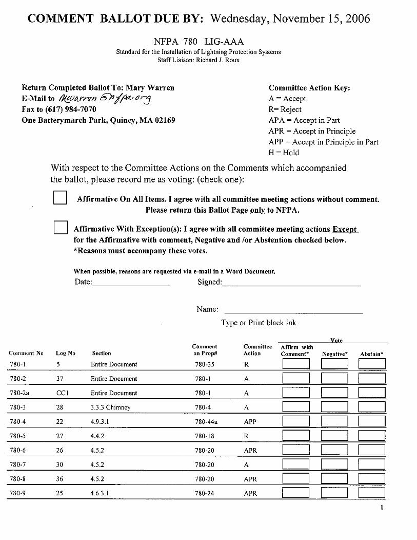
COMMENT BALLOT DUE BY: Wednesday, November 15 , 2006
NFPA 780 LIG-AAAStandard for the Installation of Lightning Protection Systems
Staff Liaison: Richard J. Roux
Return Completed Ballot To: Mary WarrenMail to II(marrm &nlfr'cJr:J
Fax to (617) 984-7070One Batterymarch Park, Quincy, MA 02169
Committee Action Key:A = AcceptR= RejectAP A = Accept in Part
APR = Accept in PrincipleAPP = Accept in Principle in PartH = Hold
With respect to the Committee Actions on the Comments which accompaniedthe ballot , please record me as voting: (check one):
Affirmative On All Items. I agree with all committee meeting actions without comment.Please return this Ballot Page to NFP A.
Affirmative With Exception(s): I agree with all committee meeting actions for the Affirmative with comment, Negative and lor Abstention checked below.*Reasons must accompany these votes.
When possible, reasons are requested via e-mail in a Word Document.
Date: Signed:
Name:
Type or Print black ink
VoteComment Committee Affirm with
Comment No L02 No Section on Prop# Action Comment" Ne2ative Abstain
780- Entire Document 780- c=J c=J c=J780- Entire Document 780- c=J c=J c=J780- CCI Entire Document 780- c=J c=J c=J780- 3 Chimney 780- c=J c=J c=J780- 780-44a APP c=J c=J c=J780- 4.4.2 780- c=J c=J c=J780- 5.2 780- APR c=J c=J c=J780- 5.2 780- c=J c=J c=J780- 780- APR c=J c=J c=J780- 780- APR c=J c=J c=J

VoteComment Committee Affirm with
Comment Nn L02 No. Section on Prop# Action Comment" Ne2ative Abstain
780- 780- c=J c=J c=J780- 780- APR c=J c=J c=J780- 3.4 780- c=J c=J c=J780- 780- APR c=J c=J c=J780- 780- APR c=J c=J c=J780- 780- APR c=J c=J c=J780- 8.2 780- c=J c=J c=J780- 780- c=J c=J c=J780- 780- APR c=J c=J c=J780- 8.3 780- c=J c=J c=J780- 3 I 8.3 780- APR c=J c=J c=J780- 780- c=J c=J c=J780- 780- c=J c=J c=J780- 780-44a c=J c=J c=J780- 3 (New) 780- c=J c=J c=J780- Figure 7.3.3.4 780- APR c=J c=J c=J780- 1.3 780- c=J c=J c=J780- 1.3 and Annex L 780- c=J c=J c=J780- 1.2 and Figure 8. 1.2 780- c=J c=J c=J780- 780- c=J c=J c=J780- 8.4.4.2 780- c=J c=J c=J780-3 I 780- c=J c=J c=J780- 8.5.5 780- c=J c=J c=J780- A.4. I.l4. 1 780- 103 c=J c=J c=J780-33a CC2 A.4. 18.4, 3.3.36 , A. 36 and 780- 105 c=J c=J c=J780- 780- c=J c=J c=J780- 8.4.2.3 780- c=J c=J c=J780- A.8.4. 780- APR c=J c=J c=J780- A.8. 780- c=J c=J c=J780- Annex B 780- 110 APR c=J c=J c=J780- Annex B 780- 110 APR c=J c=J c=J780- Annex B 780- 110 c=J c=J c=J

VoteComment Committee Affirm with
Comment Nn L02 No. Section on Prop# Action Comment" Ne2ative Abstain
780- Annex B 780- 110 c=J c=J c=J780- 780-98a c=J c=J c=J780- L.2 780- 120 APR c=J c=J c=J

ort on Comments - June 2007 NFPA 780
780- Log #5(Entire Document)
Final Action: Reject
Submitter: Matthew Caie, ERICO, Inc.Comment on Proposal No: 780-Recommendation: Reconsider Proposal 780-35.Substantiation: This proposal was rejected on the basis that the placement of air terminals at a distance of up to 2 ftfrom a likely strike point on a structure has not caused any problems . However, No substantiation was provided to backthis claim , e. , the types and heights of buildings, the lightning activity in the regions supposedly identified, quantitativeresuits of field studies, etc. If a proper field survey is carried out and examples are found where the 2 ft distance is , assuspected, too large in high lightning areas and on taller structures , the whole issue would need to be re-opened. Aquantitative study was carried out recently (1) and presented in three different international forums. It showed that afixed 2 ft rule is not appropriate and for short rods, like the ones typically installed in the USA (10 in. or 12 in. length),the 2 ft rule is much too loose for protecting vuinerable points on structures. The study also showed that the maximumdistance is dependent on the height of air terminal that is installed. Furthermore , if one considers what is recommendedin other international standards such as the IEC , 10 in. and 12 in. rods wouid need to be installed much closer that theallowable 2 ft distance. For example, IEC62305-3 shows that the "protection angle method" can be used in this situationfor structures up to 200 ft in height. Appendix E, Figure E.12, clearly shows that if a rod is positioned near an edge orcorner of a building, the height of the rod and the building are applied in the normative Table 2 of the standard. Taking a10" rod as an example , the maximum distance from the edge or corner of the structure that is allowable for structureheights in the range 16- 200 ft is 2. 2 - 0.35 ft. This range is based on Level III protection , which is essentially equivaientto the single protection level used in NFPA 780 (150 ft rolling ball etc.). From (1), the recommended maximum distancefor 10 in. rods on a 165 ft building is 0.27 It, in good agreement with the value determined from the iEC standard. Sothe question remains - what is the basis or justification for the 2 ft rule in NFPA 780 and the reason to reject a rigorousquantitative analysis that agrees with the iEC standard?Committee Meeting Action: RejectCommittee Statement: See Committee Action and Statement on 780- 15 (Log #8).
Printed on 10/31/2006

Report on Comments - June 2007 NFPA 780
780- Log #37(Entire Document)
Final Action: Accept
Submitter: Melvin K. Sanders, Ankeny, IAComment on Proposal No: 780-Recommendation: In the Committee action to "Accept in Principle" in C. , the formuia in parenthetical brackets
should be rewritten as follows:(voltage = current times resistance)
Substantiation: This change will correctly reflect the mathematical fonmulae symbols of "V = I x R"
Committee Meeting Action: Accept
Printed on 1013112006

ort on Comments - June 2007 NFPA 780
780-2a Log #CC1(Entire Document)
Final Action: Accept
Submitter: Technical Committee on Lightning ProtectionComment on Proposal No: 780-Recommendation: In 4. , change "Rolling Sphere Model." to "Rolling Sphere Method.
in 4. 1 (C), change "rolling sphere model" to " rolling sphere method.In 4. 3 (draft), change "rolling sphere model" to "rolling sphere method."In 4. 3.4 , change "rolling sphere modei" to "rolling sphere method.In 4. 2.4, change "rolling sphere model" to "rolling sphere method.
Substantiation: The committee intends to ensure consistency of terms of "rolling sphere model" and "rolling spheremethod.
" "
Rolling sphere method" is preferred.Committee Meeting Action: Accept
Printed on 10/31/2006
Report on Comments - June 2007 NFPA 780
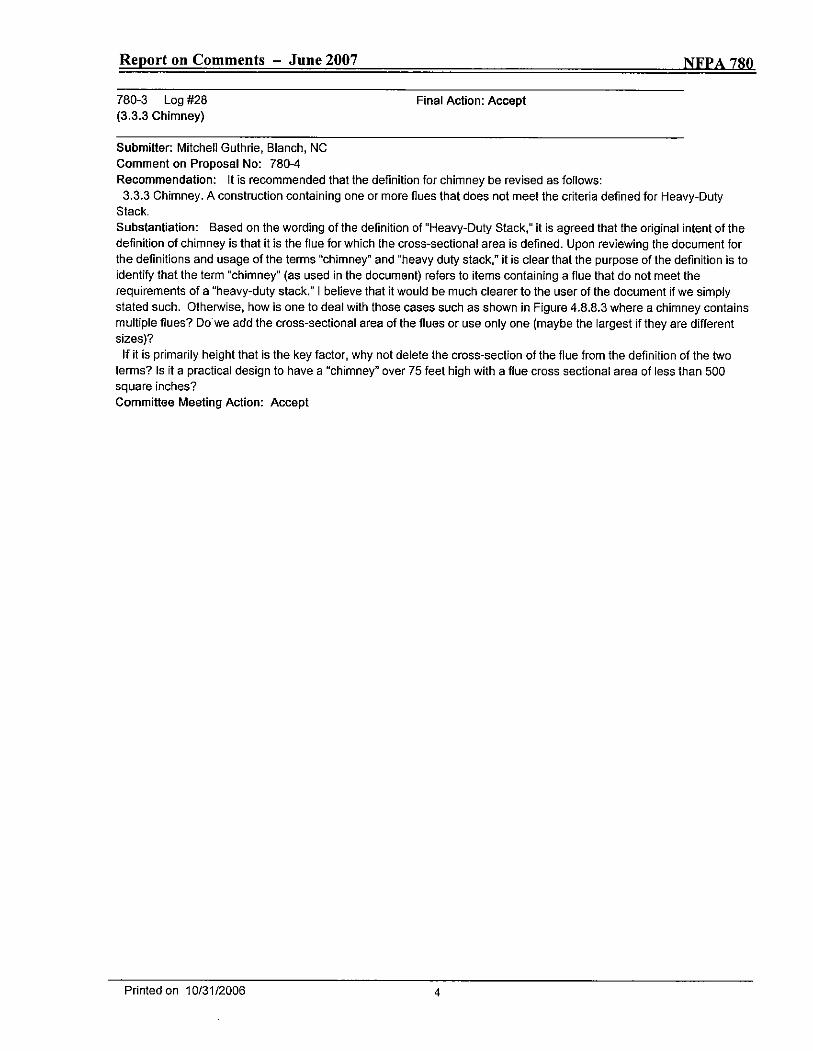
780- Log #28(3. 3 Chimney)
Final Action: Accept
Submitter: Mitchell Guthrie, Blanch, NCComment on Proposal No: 780-4Recommendation: It is recommended that the definition for chimney be revised as follows:
3 Chimney. A construction containing one or more fiues that does not meet the criteria defined for Heavy-DutyStack.Substantiation: Based on the wording of the definition of "Heavy-Duty Stack," it is agreed that the original intent of thedefinition of chimney is that it is the flue for which the cross-sectional area is defined. Upon reviewing the document forthe definitions and usage of the temns "chimney" and "heavy duty stack," it is clear that the purpose of the definition is toidentify that the temn "chimney" (as used in the document) refers to items containing a flue that do not meet therequirements of a "heavy-duty stack." I believe that it would be much clearer to the user of the document if we simplystated such. Otherwise, how is one to deal with those cases such as shown in Figure 4. 3 where a chimney containsmultiple flues? Do we add the cross-sectional area of the flues or use only one (maybe the largest if they are differentsizes)?
If it is primarily height that is the key factor , why not delete the cross-section of the flue from the definition of the twotemns? Is it a practical design to have a "chimney" over 75 feet high with a flue cross sectional area of less than 500square inches?
Committee Meeting Action: Accept
Printed on 10/31/2006
ort on Comments - June 2007 NFPA 780
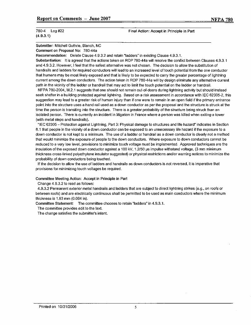
780- Log #22(4.
Final Action: Accept in Principle in Part
Submitter: Mitchell Guthrie , Blanch , NCComment on Proposal No: 780-44aRecommendation: Delete Clause 4. 2 and retain "ladders" in existing Clause 4.Substantiation: It is agreed that the actions taken on ROP 780-44a will resolve the conflict between Clauses 4.and 4. 2. However, I feel that the safest alternative was not chosen. The decision to allow the substitution ofhandrails and ladders for required conductors will lead to an increased level of touch potential from the one conductorthat humans may be most likely exposed and that is iikely to be expected to carry the greater percentage of lightningcurrent among the down conductors. The action taken in Rap 780-44a will by design eliminate any alternative currentpath in the vicinity of the ladder or handrail that may act to limit the touch potential on the ladder or handrail.
NFPA 780-2004 , M. 1 suggests that one shouid not remain out-of-doors during lightning activity but should insteadseek shelter in a building protected against lightning. Based on a risk assessment in accordance with IEC 62305- , thissuggestion may lead to a greater risk of human injury than if one were to remain in an open field if the primary entrancepoint into the structure uses a hand raii used as a down conductor as per the proposal and the structure is struck at thetime the person is transiting into the structure. There is a greater probabiiity of the structure being struck than anisolated person. There is currently an incident in litigation in France where a person was kilied when exiting a tower(with metal steps and handrails).
lEG 62305 - Protection against Lightning, Part 3: Physical damage to structures and life hazard" indicates in Section1 that people in the vicinity of a down conductor can be exposed to an unnecessary life hazard if the exposure to a
down conductor is not kept to a minimum. The use of a ladder or handrail as a down conductor is clearly not a methodthat would minimize the exposure of people to the down conductors. Where exposure to down conductors cannot bereduced to a very low level , provisions to minimize touch voltage must be implemented. Approved techniques are theinsulation of the exposed down conductor against a 100 kV 2/50 ~s impulse withstand voltage, (3 mm minimumthickness cross-linked polyethylene insulator suggested) or physical restrictions andlor warning notices to minimize theprobability of down conductors being touched.
If the decision to allow the use of ladders and handrails as down conductors is not reversed , it is imperative thatprovisions for minimizing touch voitages be required.
Committee Meeting Action: Accept in Principle in PartChange 4. 2 to read as follows:
2 Permanent exterior metal handrails and ladders that are subject to direct lightning strikes (e.g., on roofs orbetween roofs) and are eiectrically continuous shall be permitted to be used as main conductors where the minimumthickness is 1.63 mm (0.064 in).Committee Statement: The committee chooses to retain "ladders" in 4.
The committee provides edit to the text.The change satisfies the submitle(s intent.
Printed on 10/31/2006

Report on Comments - June 2007 NFPA 780
780- Log #27(4.4.
Final Action: Reject
Submitter: Mitcheil Guthrie , Blanch , NCComment on Proposal No: 780-Recommendation: Revert to the existing wording.Substantiation: There is absolutely no benefit gained from the proposed change. The existing wording says exactlywhat is intended and is perfectly clear to the user of the document. The definition of bonding makes it clear that a bondis an electrical connection so the proposal appears oniy to be making a change for the sake of change without anynoticeable benefit to the document.Committee Meeting Action: RejectCommittee Statement: "Bonded" correctly defines the required connection.
Printed on 10/31/2006

ort on Comments - June 2007 NFPA 780
780- Log #26(4.
Final Action: Accept in Principle
Submitter: Mitchell Guthrie, Blanch, NCComment on Proposal No: 780-Recommendation: It is recommended that the committee statement be amended to refiect the reason the proposalwas changed by the committee and that the revised wording be changed as follows:
2 Aluminum materials shall not be used within 460 mm (8 in. ) of the point where the lightning protection systemconductor, etc. comes into contact with earih.Substantiation: The intent of the committee in accepting the proposal in principle and adding the limitation that it isoniy applicable to aluminum materials on the exterior of the buiiding was to make it clear that aluminum materials maybe used below grade on the interior of a structure even if it is installed on an exterior wall that is less than 8- inches thick.This intent is not properly reflected in the committee statement. This is important because I do not believe it is the intentof the committee that aluminum materials may be used where they come into direct contact with earth even if it isinternal to the structure; as is allowed by the committee s proposed wording. Proposed revised wording is forwarded toindicate that aluminum is not allowed within 460 mm of the point at which the conductor enters the earth , whether thispoint is internal or external. This will allow aluminum material to be used on an external wall as long as it does not "enterthe earth" or is within 8 inches of that point.Committee Meeting Action: Accept in PrincipleCommittee Statement: See Committee Action and Statement on 780-7 (Log #30). The committee corrects 8 in. to 18in.
Printed on 10/31/2006
ort on Comments - June 2007 NFPA 780
780- Log #30(4.
Final Action: Accept
Submitter: John M. Tobias , US Army CELCMCComment on Proposal No: 780-Recommendation: Revise 4. 2 to read:Aluminium materials shall not be used within 460 mm 118 in. ) of the Doint where the liahtnina Drotection svstem
conductor comes into contact with the earth.Substantiation: Section 4. 2 as accepted by the commillee in the A2007 ROP did not consider the possibility of usingaluminum material an the interior of a structure below grade. This revision is more clear and meets the intent ofpreventing corrosion on aluminum lightning protection components.This is not original material: its reference/source is as follows:NFPA 780 ROP A2007.Committee Meeting Action: Accept
Printed on 10/31/2006

Report on Comments - June 2007 NFPA 780
780- Log #36(4.
Final Action: Accept in Principle
Submitter: Melvin K. Sanders, Ankeny, IAComment on Proposal No: 780-Recommendation: Change the Committee s "Accept in Principle" text to read as follows:
2 Aluminum materials u" II,~ ~AI~, ;u, u f II,~ bu ;IJi, ,~ shall not be used on the exterior or within the interior wherewithin 460 mm (18 in.) of the Doint where the liohtnino Drotection svstem conductor comes into contact with earth serif-"u, i"w"lacl" ill,ouSubstantiation: If the intent is as Mr. Guthrie states is to make clear to the user that use of aluminum materials are tobe prohibited within 18 in. of the contact point to earth , this should be more clearly indicated. This will also clarify to theuser that use of aluminum material along interior walls below grade will also be permitted even though they are not 18in. minimum thickness.Committee Meeting Action: Accept in PrincipleCommittee Statement: See Committee Action and Statement on 780-7 (Log #30).
Printed on 10/31/2006

ort on Comments - June 2007 NFP A 780
780- Log #25(4.
Final Action: Accept in Principle
Submitter: Mitcheil Guthrie, Blanch , NCComment on Proposal No: 780-Recommendation: i concur with the submitter s proposal to include "overturning" and "displacement" and recommendthe action taken by the committee be modified to accept the proposal versus accept in principle with the removal of theterm "overturning.Substantiation: Webster s New World Dictionary defines displacement as being moved from its customary place.While it is agreed that a literal interpretation of the definition would include overturning, this may not be obvious to ailAHJs.Committee Meeting Action: Accept in PrincipleCommittee Statement: See Committee Action and Statement on 780-10 (Log #35).
Printed on 10/31/2006

ort on Comments - June 2007 NFPA 780
780-10 Log #35(4.
Final Action: Accept
Submitter: Melvin K. Sanders, Ankeny, IAComment on Proposal No: 780-Recommendation: The original proposal to add displacement" to the present text should have been a straightAccept" so it would read as follows:
1 Air terminais shall be secured against overturning or disclacement by one the of the following...Substantiation: "Overturning" is sometimes assumed to be completely turned upside down and displacement aloneseems more in line with sizing a battleship. The two words together will be beneficial to the AHJ.Committee Meeting Action: Accept
Printed on 10/31/2006
Report on Comments - June 2007 NFPA 780
780-(4.
Log #4 Final Action: Accept in Principle
Submitter: Matthew Caie, ERICO, Inc.Comment on Proposal No: 780-Recommendation: Continue to accept Committee Action and add an additional sentence as follows: "As wind turbinesare unique structures , the zones of protection shall include the supporting structure and overall blade rotation perimeter;refer to Annex 0."Add a new Annex 0 with title to read as follows: "Annex 0 WIND TURBINE GENERATOR SYSTEMS"Annex 0 text to read as follows: 'This annex is not a pari of the requirements of this NFPA document but is included
for informational purposes only.Damage to wind turbines due to lightning strokes has been recognized as an increasing problem due to the increasing
number and height of installed turbines. Wind turbines present a unique lightning protection problem due to theirphysical construction of insulating composite materials, such as giass fiber reinforced piastic or other non-conductivematerials. The lightning protection system therefore typically has to be fully integrated into the different paris of the windturbines to ensure that all parts likeiy to be lightning attachment points are able to withstand the impact of the lightningand that the lightning current may be conducted safely from the attachment points to the ground without unacceptabledamage or disturbances to the systems."Substantiation: An annex is required to provide the level of protection required for these unique structures. Thismaterial is intended to provide some general guidance in the protection of typical wind turbines and similar stylestructures.
It is my understanding that Annex 0 was proposed , developed and accepted by the Technical Committee during theROP , then excluded due to various copyright concerns.Given the amount of growth today within this industry, the protection of wind turbines requires national guidelines be
established for wind turbine protection.My comment is that this proposed text be included in the current revision and that consideration be provided for the
following reasons:1. The text was written upon request of the committee to be based around existing IEC standards; pemnission was sort, and to my knowledge, granted before the work was undertaken.
2. The US represents to IEC , and therefore is able to take from relevant IEC documents and apply locally.Again the proposal was worked by the NFPA 780 Task Group, accepted during the ROP , and there is need for this
material in the industry.
Committee Meeting Action: Accept in PrincipleAdd new 5.8 to read as follows:
8 Wind Turbines. Where a lightning protection system is provided for wind turbines, zones of protection shall includethe supporting structure and overall blade rotation perimeter; refer to Annex O.
Include 780- 11final.doc
'..'
Add the foliowing to the end of Annex N. 1 to read as follows:iEC 61400-24, Wind Turbine Generator Systems Part 24: Lightning Protection 2002.Add the following to the end of Annex N. 2.4 to read as follows:Cotton , I.; Jenkins , N. "Lightning Protection of Wind Turbines, Lightning Protection 98 , Buildings , Structures and
Electronic Equipment, International Conference and Exhibition , Paper 6 " Solihull , West Midlands, UK , 6-7 May 1998.Alessandro , F. ; Havelka , M. "Eiectrical Grounding of Wind Turbines, " EEA Annual Conference , AUCKLAND , New
Zealand , 17-18 June 2005.Committee Statement: The committee accepts the submitter s recommendation and provides edit to the text. Thechange satisfies the submitter's intent.The committee chooses to relocate the text to Chapter 5 as a wind turbine is considered to be a miscellaneous
structure.
Printed on 10/31/2006

Annex 0 Wind Turbine Generator Systems
This annex is not a part of the requirements of this NFP A document but is included forinformational purposes only.
1 General. Damage to wind turbines due to lightning has been recognized as agrowing problem due to the increasing number and height of installed turbines. Windturbines present a unique lightning protection problem due to theirphysical construction of insulating composite materials , such as glass fiber reinforcedplastic or other non-conductive materials. The lightning protection system typicallyhas to be fully integrated into the different parts of the wind turbines to ensure that allparts likely to be lightning attachment points are able to withstand the impact of thelightning and the lightning current may be conducted safely from the attachment pointsto the ground without experiencing damage or disturbances to the systems. Whilephysical blade damage is the most expensive and disruptive damage caused bylightning, by far the most common is damage to the control system. Unlike lightningdamage to wind turbine blades , damage to control systems comes from both direct andindirect sources.
1.1 Protection of Wind Turbine Blades. Modern turbine blades are typicallyconstructed of composite materials such as carbon or glass reinforced plastic. Someparts and discrete components such as mounting flanges , balancing weights , hingesbearings , wires , electrical wiring, springs , etc. are made of metal. Lightning strikesblades that have metallic and non-metallic components. The technical challenge in thedesign of lightning protection of wind turbine blades is to conduct the lightningcurrent safely from the strike attachment point to the hub , in such a way that theformation of a lightning arc inside the blade is avoided. This can be achieved bydiverting the lightning current from the strike attachment point along the surface to theblade root, using metallic conductors , either fixed to the blade surface or inside theblade.
Typically for blades up to 20 m (60 ft.) long, receptors at the tip of the blade areadequate. However, it may be necessary for longer blades to have more than onereceptor to obtain the desired interception efficiency. Protection of the blades isprovided by the blade manufacturer and is typically an integral part of the blade.
Any wiring for sensors placed on or inside blades should be protected via bonding tothe down conduction system. Wiring should either be shielded cables or placed inmetal tubes. The cable shield or metal tube should be placed as close as possible to thedown conductor and bonded to it.
1.2 Protection of Wind Turbine Structures. With the blade being provided withintegral protection , the wind turbine should be protected in accordance with the mainbody of this standard. The placement of air terminals on parts of the wind turbinestructure other than the blades is to be determined with reference to Chapter 4 of thisstandard. Specifically, when determining protection zones, the blades are assumed tobe stationary within the "worst case" scenario position (where the blades are orientedso they provide the smallest zone of protection to the structure). The materials usedfor lightning protection of wind turbine blades should be able to withstand the electricthermal and electro-dynamic stresses imposed by the lightning current. Minimum
780/L4/A07/ROC

dimensions for materials used for air termination and down conduction are provided inChapter 4 of this standard.
1.3 Protection of Bearings and Gearbox. Arcing between bearing raceways androlling elements can dissipate sufficient energy to cause severe pitting. Such damagemay not be identified as being caused by lightning and can result in a greatly reducedlifetime of the bearing. It is possible that large heavily loaded bearings and stationarybearings may be able to conduct the lightning current without significant damage.Therefore lightning protection of the slow moving pitch bearings and yaw bearingsmay not be needed.
For additional protection or in the case of lighter weight bearings , it is recommendedthat an alternative supplemental current path be provided across the bearings with aflexible conductor , a sliding contact or similar arrangement.
1.4 Protection of Electrical and Control System. Lightning currents can inducetransients into circuits through various coupling mechanisms such as conductioncapacitive and magnetic coupling. The following are general recommendations to limitthese coupling mechanisms:
I. Providing preferential, low impedance paths for the lightning current canminimize conductive coupling. Proper separation distances and good bondingtechniques as defined in Section 4 of this standard can prevent flashovers.
2. Capacitive coupling between conductors designed to carry the lightning current
and a component (cable andlor electrical equipment) can be reduced by:shielding (a complete metal enclosure, braided wire sheath or wire mesh
screen)increasing the distance between lightning conductors and such components(e. , move the wires close to a ground plane , use grounded metallic conduitwireways or raceways)
3. Magnetic coupling to electrical or control cabling and equipment can bereduced by:
metal enclosures (raceways , pipes, shields , metal box)avoid forming large- loop areaS with electrical or control cablingkeep conductors close to metal components such as gearboxes andgeneratorstwisted pairing of cables can reduce magnetic coupling
Bonding within the wind turbine is required to reduce voltage differences betweenparts of the wind turbine. This bonding provides protection against touch and stepvoltages during a lightning strike.
Electrical power equipment such as motors , generators , transformers , and switchgear isdesigned to withstand high-voltage surges. Insulation of electrical power equipmentnormally withstands transient voltages in the kilovolt range. It is recommended that asurge protection device (SPD) rated above the operating line voltage and possibletemporary over voltages be used. Otherwise , the SPD may conduct current duringnormal line variations and have greatly reduced service life. Further guidelines for theapplication of SPDs are found in Section 4. 18 of this document and ANSI/EEE 62.41.

Signal circuits can only withstand transient voltages of some tens of volts and suchcircuits are susceptible to transient over voltages particularly in such an exposedenvironment of a wind turbine. Depending on the nature of the equipment beingprotected, the correct array of SPDs should be selected and installed as close aspractical to the equipment to be protected.
2 Blade- to-Hub Connection. At the base of the blade , the down conductor systemis usually either terminated to the blade-mounting flange or to the hub.
Blades could be either pitch regulated or equipped with a tip brake. In such cases , thehydraulic control or pitch bearing is required to be protected using either a slidingcontact or a flexible bonding cable with enough slack to allow for motion. Thisbonding is required to provide a preferred path for the lightning energy from the bladeconductor to the hub.
Care must be taken to reduce the slack in such bonding straps, since the inductivevoltage drop across the slack may become very high , thus resulting in inefficientprotection.
3 Grounding. Each wind turbine must be equipped with its own groundingelectrode system , and interconnected to a site grounding system , if present. Thelightning protection system grounding should be designed in accordance with theminimum requirements of this standard. However, consideration should be given totypical factors in a power generation facility such as sizing conductors for faultcurrents , and touch and step potential requirements. These factors are outside thescope of this annex. The grounding of a wind turbine would then comprise a groundring electrode external to the structure (defined by the radius of the turbinefoundation) in contact with the soil , bonded to the foundation reinforcing bars.Additional vertical and horizontal grounding electrodes may be used in combinationwith the ring electrode. The ring electrode should be buried to a depth of at least 460mm (18 in. ). Horizontal electrodes may be used to connect the grounding system ofone wind turbine to the site grounding system. The lightning protection groundingelectrode must always be bonded to the power grounding system.
780/L4/AO7/ROC

ort on Comments - June 2007 NFPA 780
780-12 Log #23(4.
Final Action: Accept
Submitter: Mitcheil Guthrie, Blanch, NCComment on Proposal No: 780-Recommendation: Change upper case "D" in Figure 4. 3 to "2R" in the formula.Change "D" to "R" in the legend where R = rolling sphere radius (46 m (150 ft))"
Substantiation: The committee action results in both a lower and upper case d" in the equation. There was somediscussion during the Rap meeting that there was confusion by some casuai users of the formula as to the source ofthe value of 300 used in the formula. The substitution of the variable "D" resolves this confusion. However , the use ofthe variable "2R" in piace of "D" (where R is the striking distance) would be even clearer as to the source and it wouldeliminate the need to use both an upper case and lower case d" in the formula.Committee Meeting Action: AcceptCommittee Statement: The committee notes the formula and legend are in 4. 3.4.
Printed on 10/31/2006
ort on Comments - June 2007NFPA 7110
780-13 Log #24(4.
Final Action: Accept in Principle
Submitter: Mitchell Guthrie, Blanch , NCComment on Proposal No: 780-Recommendation: The committee action should be to Accept in Principle with the following revision:
2 The zone of protection shattfonm is defined as a cone whose apex is located at the highest point of the striketermination device , with watts surface form!W.ing'!1Y. a 45-degree or 63-degree angle from the vertical.
Substantiation: The proposed revision is incorrect. First , the zone of protection is defined as a volume , not a surface.Second , a "surface" is not typically considered to have an apex as an "apex" is defined by Webster s Dictionary as: (1)the highest point or (2) the usually pointed end of an object.Committee Meeting Action: Accept in PrincipleChange 4. 2 to read as follows:
2 The zone of protection is a cone with the apex located at the highest point of the strike termination device , withits surface formed by a 45-degree or 63-degree angle from the vertical.Committee Statement: The committee accepts the submitter s recommendation and provides edit to the text. Thechange satisfies the submitte~s intent.
Printed on 10/31/2006

Report on Comments - June 2007 NFPA 780
780-14 Log #34(4.
Final Action: Accept in Principle
Submitter: Meivin K. Sanders , Ankeny,
Comment on Proposal No: 780-Recommendation: The present text of NFPA 780-2004 should be retained and modified as follows:
2 The zone of protection shall form a cone whose apex is located at the highest point of the strike terminationdevice , with watts its outer surface forming a 45-degree or 63-degree angle from the vertical.Substantiation: "Zone of Protection " is already defined in 3. 35 as a surface, and the Committee s "Accept inPrinciple" of " line of protection " does not follow that meaning. Mr. Guthrie s suggestion to provide a new definition ofZone of Protection" is not in agreement with the present definition , and that issue should be addressed there if
additionai ciarity is needed. A (virtual reality) cone provides a surface voiume concept for evaiuation by use~s as to theincluded areas more likely to be so protected. The Accept in Principle use of the phrase "a line" indicates a one or twodimension flat surface and does not convey the meaning inherent in the original text of a three dimensional space.Committee Meeting Action: Accept in PrincipleCommittee Statement: See Committee Action and Statement on 780-13 (Log #24).
Printed on 10/31/2006

ort on Comments - June 2007NFPA 780
780-(4.
Log #8 Final Action: Accept in Principle
Submitter: John M. Tobias, US Department of the ArmyComment on Proposal No: 780-Recommendation: See the following figures:
Existing:2 Location of Devices. As shown in Figure 4. 2, strike termination devices shall be piaced at or within 0.6 m (2 It)
of ridge ends on pitched roofs or at edges and outside corners of flat or gently sioping roofs.
INSERT Figure 4.
Change to:2 Location of Devices. For Class i installations, where the roof height does not exceed 75 It. , strike termination
devices shall be placed at or within 0.6 m (2 It) of ridge ends on pitched roofs or at edges and outside corners of flat orgently sloping roofs, as shown in Figure 4. 2a. For Class II installations , this spacing between the strike terminationdevice and the roof edge shall not exceed the height of the strike termination device above the roof edge level , asshown in Figure 4. 2b.
INSERT Figure 4.
iNSERT Figure 4.
Substantiation: Rejection of the original proposal 780-35 leaves an established gap In lightning protection for tallerstructures. Yet , the proposal as originally written was too restrictive for Class I structures. (See voting explanations inRap A2007.) This comment addresses the need to place air terminals closer to a roof edge for class II structures inorder to minimize the possibility of bypass and attachment to a roof edge. In addition , this comment brings NFPA 780air terminal placement requirements into closer coordination with IEC lightning protection standards.
Information presented (by Dr. D'Alessandro) at May 2005 Pre-Rap meeting indicated that there are a number ofbypasses ' where corners of buildings are struck despite the presence of a strike termination. Using other sources (for
example derived from Tobias, J. M. , ed. The Basis of Conventional Lightning Protection Technology, FederalInteragency Lightning Protection Group, Availabie on www.stinet.dtlc.mil , Report No. ADA396784 , p. 21 , June 2001) theeffective protection angle for short distances is agreed to be 45 degrees. By requiring that the air terminal is placed at adistance not to exceed its height above the protected object , the 45 degree protection angle is enforced.
Further consideration given to this issue in the 780 2007 ROP noted that the distance of air terminals to roof edge wasdependent upon height of the structure, as Mr. Caie notes, referring to well established IEC standards. This commentaddresses that point in the context of NFPA 780 techniques and terminology and brings 780 into closer coordinationwith IEC lightning protection standards.Additional Substantiation (From A2007 Rap voting explanations)Explanation of Negative:CAIE , M. : This proposai was rejected on the basis that the placement of air terminals at a distance of up to 2 It from a
likeiy strike point on a structure "has not caused any problems . However:. No substantiation was provided to back this claim , e. , the types and heights of buildings , the lightning activity in the
regions supposediy identified , quantitative results offield studies , etc.. if a proper fieid survey is carried out and examples are found where the 2 It distance is , as suspected , too large in
high lightning areas and on taller structures , the whole issue would need to be re-opened.A quantitative study was carried out recently (1) and presented in three different internationai fora. It showed that a
fixed 2 It rule is not appropriate and for short rods , like the ones typically installed in the USA (10" or 12" length), the 2 Itrule is much too loose for protecting vuinerable points on structures. The study also showed that the maximum distanceis dependent onthe height of air terminal that is installed.
Furthermore , if one considers what is recommended in other international standards such as the IEC , 10" and 12" rodswould need to be installed much closer that the allowable 2 It distance. For example , IEC62305-3 shows that the
Printed on 10/31/2006

Report on Comments - June 2007 NFPA 780protection angle method" can be used in this situation for structures up to 200 It in height. Appendix E, Fig. E.12 , clearly
shows that if a rod is positioned near an edge or corner of a building, the height of the rod and the building areapplied in the normative Table 2 of the standard.Taking a 10 in. rod as an example, the maximum distance from the edge or corner of the structure that is allowable for
structure heights in the range 16 - 200 It is 2.2 - 0.35 It. This range is based on Levei III protection , which is essentiallyequivalent to the single protection level used in NFPA 780 (150 It roiling ball etc. ). From (1), the recommendedmaximum distance for 10 in. rods on a 165 It building is 0.27 It, in good agreement with the value determined from theIEC standard.
, the question remains - what is the basis or justification for the 2 It rule in NFPA 780 and the reason to reject arigorous quantitative analysis that agrees with the IEC standard?References
(1J D'Alessandro , F. , 2004
, "
Improved placement of protective lightning rods on structures Proc. Internat. ContGrounding Eat1hing (Ground'2004), Belo Horizonte , Brazil , pp. 138- 143.(2J International Electrotechnical Committee, " IEC 62305-3 Ed. 1.0: Protection against lightning - Part 3: Physicai
damage to structures and life hazard", CEI , Geneva, Switzerland , 2006.TOBIAS , J. : Comments from Caie are correct and need consideration. Sufficient substantiation exists for the original
proposal.Comment on Affirmative:GUTHRIE , M. : I agree with the concept of the original rejected proposal but also agree with the committee s decision to
reject the proposal at this time. A preference would be to accept the original proposai in principle with some revision tothe text to reflect the principles cited by Mr. Caie in his negative vote. However, I do not believe we are at the pointwhere we can reach agreement on the specific text at this point. Mr. Caie references the D'Alessandro Ground 2004paper as a primary justification for the need for this change and indicates that it shows the 2-foot rule is much too loosefor protecting vulnerable points on structures. He also cites iEC 62305-3 as justification for this change. In response , it
should be identified that NFPA 780 is one of the more stringent of the standards in use in the world as it relates tospacing of air terminals from the corners of a protected structure. It is aiso unclear whether any of the bypassesdiscussed in the D'Alessandro paper were associated with installations where the air terminal spacing met the existingrequirements of NFPA 780. It is also interesting that the example given by Mr. Caie considers a structure of 165 feetheight. It should be noted that the protective angle specified in IEC 62305-3 changes as a function of height of thestructuretair terminal. IEC 62305-3, 5. 2 identifies that a 45-degree angle would be excessive for structures of less than30 meters in height. For a 10- meter tall structure, the IEC 62305-3 protective angie exceeds 60 degrees. In thesecases , the 2-foot spacing is exceedingly conservative. In conclusion , I agree that the 2-foot spacing should be assessedfor tall structures such as the 165-foot tall structure discussed by Mr. Caie. However, I believe it would be excessive torequire that the 45-degree angle be applicable across the board as proposed in ROP 780-35.Committee Meeting Action: Accept in Principle
Change 4. 2 to read as follows:2. Location of Devices. As shown in Figure 4. 2, the distance between strike termination devices and ridge ends
on pitched roofs or edges and outside corners of flat or gently sloping roofs shall not exceed 0.6 m (2 It).Add annex A.4. 2 to read as follows:A.4. 2 Strike termination devices should be placed as close as practicable to roof edges and outside corners.Committee Statement: The committee changed the text of 4. 2 to emphasize that strike termination devices shouldbe installed close to roof edges. Annex material was added to encourage minimizing air terminal to edge distance.The change satisfies the submitter s intent.
Printed on 10/31t2006

ort on Comments - June 2007 NFPA 780
780-(4.
Log #40 Final Action: Reject
Submitter: Mark P. Morgan , East Coast Lightning Equipment, Inc.Comment on Proposal No: 780-Recommendation: The Committee s rejection of this proposal is correct.Substantiation: I agree with the comment on affirmative by M. Guthrie a~ it relates to M. Caie s Explanation ofNegative vote on the rejection of this proposal. The information presented by F. D'Alessandro regarding by-passes of airterminals does not constitute a "rigorous quantitative analysis" as relates to NFPA 780 requirements, because none ofthe by-pass evidence presented occurred in systems installed in accordance with NFPA 780.Committee Meeting Action: RejectCommittee Statement: The submitter did not provide a recommendation for consideration in accordance with theRegulations Governing Committee Projects, Section 4- 3(c).
Printed on 10/31/2006
ort on Comments - June 2007 NFPA 780
780-17 Log #2(4.
Final Action: Reject
Submitter: Harold VanSickle, III , Lightning Protection InstituteComment on Proposal No: 780-Recommendation: Delete 4. Pitched Roof Area entirely including all of paragraph (A) and (8).Substantiation: The original submitter has outlined a valid probiem with the installation of system components at theeave line for ridged roof structures. Following the requirements of NFPA 780 creates a hazard to people below thebuilding perimeter, as well as a situation where proper compliance leads to system components being ripped out of theconstruction breaking the moisture seal of the structure s exterior in cold climates with snow and ice accumulation.There are substantial enough negative consequences associated with compliance to these paragraphs that owners areforced to either ignore or risk their property and the peopie below. The vote to reject by the NFPA 780 Committee cites the original submitter s lack of providing adequate substantiation.
He has indicated the problem and the need to delete the paragraphs. I would also point out that later in this samemeeting, the NFPA 780 Committee accepted Proposal No. 780-100 that speaks to a very similar issue. When theCommittee justifies not protecting the top vertical edges of tall buildings that are subiect to direct strikes , then theCommittee has provided it's own justification for not protecting eave lines on tall , ridged roof structures. Protection ofeave lines "will not normallv be iustified" because it leads to negative consequences for performance of the constructionfor any reasonable period of time.This is not original material: its reference/source is as follows:
Committee Meeting Action: RejectCommittee Statement: Removal of these paragraphs creates inconsistencies in other areas of the NFPA 780document.The submitter has not provided adequate substantiation.The committee does not agree with the submitte~s substantiation.
Printed on 10/31/2006

Report on Comments - June 2007 NFPA 780
780-(4.
Log #7 Final Action: Accept in Principle
Submitter: John M. Tobias , US Department of the ArmyComment on Proposal No: 780-41Recommendation: Add new text to read as follows:
1 Wind Turbines. Zones of Protection for Wind Turbines will consider their biade diameter and have no Dartoutside of a zone of orotection afforded bv the blades.
See Annex for additional information.NFPA 780 new ANNEX MATERIAL FOR 4.WIND TURBINE GENERATOR SYSTEMS -
INTRODUCTIONDamage to wind turbines due to lightning strokes has been recognized as an increasing problem. The increasing
number and height of installed turbines have resulted in an incidence of lightning damage greater than anticipated withrepair costs beyond acceptable levels. Wind turbines pose a unique lightning protection problem due to their physicalsize and nature. There is extensive use of insulating composite materials , such as glass fibre reinforced piastic , as ioadcarrying parts. The lightning protection system has to be fully integrated into the different parts of the wind turbines toensure that all parts likely to be lightning attachment points are able to withstand the impact of the iightning and that thelightning current may be conducted safely from the attachment points to the ground without unacceptable damage ordisturbances to the systems. The specific problems to modern wind turbines are a result of the following:- wind turbines are frequently placed at locations very exposed to lightning strokes;- the most exposed wind turbine components such as blades are often made of composite materials incapable of
sustaining direct lightning stroke or of conducting lightning current;- the biades are rotating:- the lightning current has to be conducted through the wind turbine structure to the ground, whereby significant parts
of the lightning current will pass through or near to practically all wind turbine componentsLightning striking unprotected biades manufactured from composite material invariabiy causes severe damage since
these materials are poor conductors of lightning current. Whiie physical blade damage has been shown to be the mostexpensive type of damage studies have shown that by far the most common was damage to the control system. Unlikelightning damage to wind turbine blades , damage to control systems comes from a number of direct and indirectsources.LIGHTNING PROTECTION OF WIND TURBINESWIND TURBINE BLADESModern wind turbine blades are large hollow structures manufactured of composite materials, such as glass reinforced
plastic (GRP), wood , wood laminate and carbon reinforced plastic (CRP). Some parts and discrete components such asmounting flanges , balancing weights , hinges, bearings , wires, eiectricai wiring, springs and fixtures are made of metal.Lightning does in fact strike blades without any metallic components, and whenever a lightning arc is formed inside theblade damage is severe. There are several types of blades depending on the controi and braking mechanism employed.Four main types are shown in Figure 1.Type A blades , lightning attachment points are often found on the steel flap hinges , and severe damage is often seen
since the cross-section of the steei wires used for operating the flap is usually insufficient for conducting the lightningcurrent.Type B biades , lightning attachment points are predominantly seen within a few feet from the outermost tip, or on the
sides of the tip at the position of the outermost end of the tip shalt. From the attachment point, a lightning arc is formedinside the tip section to the outermost end of the tip shalt , and from the other end of the shalt an arc is formed inside themain biade down to the steei-mounting flange at the blade root. Such internal arcs invariably cause catastrophicdestruction to the blade.Type C blades, lightning attachment points are predominantly found within a few tens of cm from the outermost tip of
the blade , or on the sides of the tip at the position of the outermost end of the tip shalt. With type C as with type B , alightning arc formed inside the tip section between the attachment point and the outermost end of the shalt causessevere damage.Type D is a blade constructed entirely from non-conducting materials. As with the other types of blades , lightning
attachment points are mostly found close to the tip. Compared to the other types of blades , attachment points can alsobe found randomly distributed at other positions aiong the iength of the blade.
Printed on 10/31/2006

Report on Comments - June 2007 NFPA 780INSERT Figure 1 HERE
Figure 1 Types of wind turbine blades.
The problem of lightning protection of wind turbine blades is to conduct the lightning current safely from the attachmentpoint to the hub, in such a way that the formation of a lightning arc inside the blade is avoided. This can be achieved bydiverting the lightning current from the attachment point along the surface to the blade root, using metallic conductorseither fixed to the blade surface or inside the blade. Another method is to add conducting material to the blade surfacematerial itseif, thus making the blade sufficiently conducting to carry the lightning current safely to the blade root.Variations of both these methods are used with wind turbine blades (see Figure 2).
INSERT Figure 2 HEREFigure 2 Lightning protection for large modern wind turbine blades.
For biades up to 20 m long, it appears that receptors at the tip of the blade are adequate. It may be necessary forlonger blades to have more than one receptor to obtain the desired interception efficiency.WIND TURBINE STRUCTUREThe protection of the biades is provided by the blade manufacturer and is an integral part of the blade as shown in
figure 2. With the blade being provided with integral protection , the wind turbine shall be protected in accordance withthe main body of this standard. The placement of air terminals on parts of the wind turbine structure other than theblades shall be determined with reference to Chapter 4. Specifically when determining protection zones , the blades shallbe assumed to be stationary within the "worst case" scenario position. The materials used for lightning protection ofwind turbine blades shall be able to withstand the electric, thermal and electrodynamic stresses imposed by the lightningcurrent. Minimum dimensions for materials used for air termination and down conduction are provided in Chapter 4 ofthis standard.
BLADE TO HUB CONNECTIONAt the root of the blade, the down conduction system is usually either terminated to the blade-mounting flange or to the
hub.If the blade is pitch regulated (type D), the lightning current is either allowed to pass uncontrolled through the pitchbearing or some kind of bonding across the bearing is provided such as a sliding contact or a flexible bonding cable withenough siack to allow for the pitch motion. The flexible bonding across the bearing can be combined with the innermostpart of the down conductor from the blade.
In blades with tip brake (type C), the hydraulic system, which actuates the control wire, must be protected. Standardhydraulic cylinders that are normally used can be damaged by flashovers from the rod to the cylinder housing. Usually,the hydraulic cylinder is protected by diverting the lightning via a flexible bonding strap with sufficient slack to allow forthe motion.
Care must be taken to reduce the slack in such bonding straps , since the inductive voltage drop across the slack maybecome very high , thus resulting in inefficient protection of the cylinder.
WIRING INSIDE BLADESWiring for sensors placed on or inside blades must be protected via bonding to the down conduction system. Wiring
shouid either be shielded cables or placed in metal tubes. The shielded cabie or metal tube shouid be placed as closeas possible to the down conductor and bonded to it.
PROTECTION OF BEARINGS AND GEARBOXArcing between bearing raceways and rolling elements can dissipate energy enough to cause severe pitting. Such
cases of delayed damage are probably never identified as being caused by lightning, however can result in a greatlyreduced lifetime of the bearing. It is possible that large heavily loaded bearings and stationary bearings may be able toconduct the lightning current without significant damage. Therefore lightning protection of the slow moving pitchbearings and yaw bearings may not be needed. It is recommended that an alternative current path be provided acrossbearings at risk with a flexible conductor, a sliding contact or similar arrangement.
PROTECTION OF ELECTRICAL AND CONTROL SYSTEMLightning currents can induce transients into circuits through various coupling mechanisms such as conduction
capacitive and magnetic coupling. The following are general recommendations to limit these coupling mechanisms:1. Providing preferential , low impedance paths for the lightning current can minimize conductive coupling. Proper
insulation levels and good bonding techniques can prevent flashovers.2. Capacitive coupling between one component and another can be reduced by:- shielding (a complete metal enclosure , braided wire sheath or wire mesh screen);- increasing the distance between the interacting components (for example move the wires close to a ground plane
use grounded metallic conduit, wire ways or race trays), and
Printed on 10/31/2006

Report on Comments - June 2007 NFP A 780
- reducing the exposed surface.3. Magnetic coupling can be reduced by:- high-frequency magnetic fields can be reduced significantly with a metal enclosure (race ways, pipes, shields, metal
box). The magnetic disturbance is deflected and dissipated as eddy currents in a metal cover;- avoid fomning iarge-Ioop areas that are susceptible to flux linkage - keep conductors close to metal components such
as gearboxes and generators;- twisted cables can reduce magnetic coupiing because the area enclosed is very small and the signai induced in the
wire pairs should cancel at differential inputs.Bonding within a wind turbine is required to establish equipotential bonds between parts of the wind turbine. These
equipotential bonds provide protection against touch and step voltages during a lightning stroke. Some considerationsfor the bonding and shielding needed in a wind turbine are discussed below. Bonding within a wind turbine shouldtherefore use multiple conductors that are:- capable of carrying the predicted fraction of lightning current to pass through the path in question;- as short and straight as possible.
Wiring can also be protected by routing wires in conduits/raceways or by using shielded cable. To prevent voltagesbeing induced into the electricai wiring it is obvious that the reduction of the peak change of magnetic fieid passingthrough a loop and the reduction of loop area will result in lower induced voltages. This can be achieved in a number ofways:
a) Increased separation between the current-carrying conductor and the electrical circuit. This method of reducinginduced voltages would work but is not nomnally possible within the confines of a wind turbine.
b) Using twisted pair cable will reduce the induced voltage level. Twisted pair systems will reduce differential modevoltages but common mode voitages may still exist;
c) Use of shielding by using shielded cabling or routing the wiring inside steel pipes or metal conduits is recommendedto effectively shield cabies from magnetic fieids. Protection is only possibie when both ends of the shield/pipe/ conduitare solidly connected to earth.
In addition to the methods listed above, installing cabling ciose to the metal structure and avoiding ioops of cabling willreduce the magnetic coupling area. These methods will effectively reduce loop areas and shield the wires inside fromthe changing magnetic fields.
Eiectrical power equipment such as motors, generators, transformers, and switchgear is designed to withstandhigh-voltage surges. insulation of electrical power equipment nomnally withstands transient voltages in the kilovolt range.In the light of this , it is recommended that a surge arrestor or SPD rated above the operating line voltage and possibletemporary overvoltages (TOV) be used. Otherwise , the surge arrestor or SPD may conduct current during nomnal linevariations and have greatly reduced service life. Further guidelines for sizing SPDs and surge arrestors are found in(state relevant IEEE , NEC standard here).
In contrast to eiectrical power equipment , signal circuits can only withstand transient voltages of some tens of volts.Such circuits are susceptible to transient overvoltages especially in the exposed environment of a wind turbine.Depending on the nature of the circuit or equipment being protected , the correct array of SPDs should be selected andinstalled as close as practical to the equipment to be protected. Newer turbines utilize fibre optics to transfer signals toavoid noise and other circuit disturbances. Fibre optics is quite suitabie to protect the signal network against lightningdamage when properly utilized. Specifically, fibre optic cables without metallic wires should be used.
GROUNDINGEach wind turbine must be equipped with its own combined ground temnination system , even if it is interconnected to a
larger wind famn grounding system. The lightning protection system grounding should be designed in accordance withthe minimum requirements of this standard , however consideration should be given to typical factors in a powergeneration facility such a sizing conductors for fault currents and touch and step potential requirements. These factorsare outside the scope of this standard. The grounding of a wind turbine shall comprise a ground ring electrode externaito the structure (defined by the radius of the turbine foundation) in contact with the soil , bonded to the foundationreinforced concrete. Additional vertical and horizontal ground electrodes may be used in combination with the ringelectrode. The ring electrode should be buried to a depth of at least 18 inches. Horizontal electrodes may be used toconnect the grounding system of one wind turbine to the next when it is within a wind farm. A typical grounding layout isprovided within figure 3. The measurement of grounding system resistance should be carried out for each individualwind turbine earthing system before it is connecting to any other cable type. The lightning protection ground temninationsystem must always be bonded to the power system earth through equipotential bonding.
INSERT Figure 3 HEREFigure 3 Typical grounding layout.
Printed on 10/31/2006

Report on Comments - June 2007PERSONAL SAFETYWind turbines are in principie safe to work in. However, during thunderstomns personnel working on wind turbines can
be exposed to additional risks. For unprotected wind turbines all lightning flashes are potentially hamnful to personneitherefore lightning protection should be part of the turbine design. Work should not be performed on wind turbinesduring thunderstorms. Safe operating procedures should include precautions for personnel safety during thunderstorms.The risks related to personnel safety at the different locations in a wind turbine during thunderstomns are addressed indetail within IEC 61400-24.
it is vital to consider the safety of the turbine operators and maintenance personnel. This would includes:0 The nacelle cover should provide maximum protection of personnel and sensors inside from direct strike (having
metal in the nacelle cover to act as temninals, conductor to ground and Faraday shield)0 Control boxes should be similariy protected (e.g., operators should be protected against direct strike shen working on
the boxes)
0 Step voltage risks should be minimized by locating controllers or tower entries within the ground eiectrode ring or ufergrounds or copper mesh beneath the common standing areas for an operator
REFERENCESIEC 61400-24: Wind Turbine Generator Systems - Part 24: Lightning ProtectionCOTTON , I.; JENKINS , N. Lightning Protection of Wind Turbines , Lightning Protection 98 , Buildings , Structures and
Electronic Equipment, International Conference and Exhibition , Paper 6, 1, Solihull , West Midlands, UK, 6-7 May 1998Alessandro , F. ; Havelka , M. Electrical Grounding of Wind Turbines , EEA Annuai Conference , AUCKLAND , New
Zealand , 17-18 June 2005McNiff, B. ; McCoy, T. ; Rhoads , H. ; Lisman , T. ; Smith , B. Lightning Activities in the DOE-EPRI Turbine Verification
Program , American Wind Energy Associations Wind Power 2000, Palm Springs, California , USA, 6April 30 - May 52000Substantiation: The proposal as written inadequateiy addresses this class of structure. The class of structuresdesignated as wind turbines , falling generally under structures with rounded roofs due to the similarity of the arc of therotating blades, need special zone of protection consideration due to the nature of the moveable assemblies and needto be addressed in this section. In order to adequately address the zone of protection issues (and the consequentissues of strike temnination) additional (non-nomnative) annex material is required for explanatory purposes.Committee Meeting Action: Accept in PrincipleCommittee Statement: See Committee Action and Statement on 780-11 (Log #4).
NFPA 780
Printed on 10/31/2006
Report on Comments - June 2007 NFPA 780
780-19 Log #6(4.
Final Action: Reject
Submitter: Matthew Caie, ERiCa, Inc.Comment on Proposal No: 780-Recommendation: None.
Substantiation: The Comment to be made here reflects that of the comment made for 780-35, Log #83 however themore stringent guidelines are necessary. Given that this section refers to chimneys and vents , protrusions such as theseon roof-tops constitute higher probabiiity strike points. The point is that there is observed evidence of such damageoccurring, this was submitted at and before the Rap.Committee Meeting Action: RejectCommittee Statement: The submitter did not provide a recommendation for consideration in accordance with theRegulations Governing committee Projects , Section 4- 3(c).
Printed on 10/31/2006

Report on Comments - June 2007 NFPA 7110
780-20 Log #31(4.
Final Action: Accept in Principle
Submitter: John M. Tobias , US Amny CELCMCComment on Proposal No: 780-42Recommendation: See the foliowing figures:
Existing:3 Required strike termination devices shali be instalied on chimneys and vents , as shown in Figure 4. 3, so
that the distance from a strike termination device to an outside corner or the distance perpendicuiar to an outside edgeshali be not greater than 0.6 m (2 It).
Figure 4. 3 (Existing Figure 4. , 2004 ed. , (no change))
Change to:3 Required strike temnination devices) shali be instalied on Class I chimneys and vents (under 75 feet in height
above grade), as shown in Figure 4. 3a, so that the distance from a strike termination device to an outside corner orthe distance perpendicular to an outside edge shali be not greater than 0.6 m (2 It).
Required strike termination devices shali be instalied on Class II (greater than 75 It. in height above grade) chimneysand vents , as shown in Figure 4. , so that the distance from a strike termination device to an outside corner or thedistance perpendicular to an outside edge shali benot greater than the height of the device above the protected chimney or vent.
Figure 4. 3" (Existing Figure 4. 3, 2004 ed. , (no change)!
INSERT Figure 4. 83b
Substantiation: Information presented at May 2005 Pre-Rap meeting indicated that there are a number of 'bypasseswhere corners of buildings are struck despite the presence of a strike termination. Using other sources (for examplederived from Tobias , J. M. , ed. The Basis of Conventional Lightning Protection Technology, Federal Interagency
Lightning Protection Group, Available on www.stinet.dtic.mii , Report No. ADA396784 , p. 21 , June 2001) the effective
protection angle for short distances is agreed to be 45 degrees. By requiring that the air terminal is placed at a distancenot to exceed its height above the protected object , the 45 degree protection angle is enforced.Also see A2007 Rap and comments to 780-35.Rejection of the original proposal 780-42 leaves an established gap in lightning protection for the talier structures. Yet
the proposal as originaliy written was too restrictive for Class I structures. (See voting explanations in Rap 2007). This
comment addresses the need to place air temninals closer to a roof edge for Class II structures in order to minimize thepossibility of bypass attachment to a roof edge. In addition , this comment brings NFPA 780 air terminal placement
requirements into closer coordination with IEC lightning protection standards.Committee Meeting Action: Accept in Principle
Add' foliowing 4.Add A.4. 3 to read as foliows:A.4. 3 Strike temnination devices should be placed as close as practicable to an outside corner.Committee Statement: The committee intends to retain the text of 4.Annex material was added to encourage placement of air terminals at corners.The change satisfies the submitter's intent.
Printed on 10/31/2006
Report on Comments - June 2007 NFPA 780
780-21 Log #39(4.
Final Action: Reject
Submitter: Mark P. Morgan , East Coast Lightning Equipment, Inc.
Comment on Proposal No: 780-42Recommendation: The Committee s rejection of this proposal is correct.Substantiation: Contrary to the assertion by M. Caie in his Explanation of Negative vote on this proposal , no air
terminal bypasses on chimneys or vents installed with NFPA 780 compliant systems was contained in the F.Alessandro information referenced as substantiation for this proposal.
Committee Meeting Action: RejectCommittee Statement: The submitter did not provide a recommendation for consideration in accordance with theReguiations Governing committee Projects, Section 4- 3(c).
Printed on 10/31/2006

ort on Comments - June 2007 NFPA 780
780-22 Log #1(4.
Final Action: Accept
Submitter: Harold VanSickle , III , Lightning Protection InstituteComment on Proposal No: 780-43Recommendation: Revise text to read as follows:
...
shall be located u" u~~uo ;l~ o ;d~o uo o~~aoal~ as far apart as practicable...Substantiation: The statement "on opposite sides or separated" adds nothing. The baiance of the wording will standalone. The Committee removed similar wording from other proposals because it doesn t apply well to circular or 5 sidedstructure housings.This is not original material; its reference/source is as follows:
Committee Meeting Action: Accept
Printed on 10/31/2006

ort on Comments - June 2007 NFPA 780
780-23 Log #33(4.
Final Action: Reject
Submitter: Melvin K. Sanders, Ankeny, IAComment on Proposal No: 780-44aRecommendation: Section 4. 2 should be deleted.Substantiation: I agree with Mr. Guthrie that use of handrails and ladders for down conductors allow for removal bypersons unfamiliar with their secondary purpose. There is a potential for personnel shock due to electrostatic chargebuild-up or rapid discharge via lightning. In addition , it also mandates additional splices that may affect the charge pathto earth , and places them in locations where nomnal maintenance and accessibility may allow unknowing damage tooccur. I believe the text was added in the 2004 edition with little technical substantiation other than it was being done insome locations.Committee Meeting Action: RejectCommittee Statement: See Committee Action and Statement on 780-4 (Log #22).
Printed on 1013112006

ort on Comments - June 2007 NFPA 780
780-24 Log #41(5. 3 (New) )
Final Action: Accept
Submitter: Mark P. Morgan , East Coast Lightning Equipment, Inc.Comment on Proposal No: 780-Recommendation: This proposed addition to the standard should be rejected.Substantiation: For the reasons stated in the negative vote explanations submitted by T. Portfleet and M. Morgan , theCommittee should reconsider its decision on this proposal. The new paragraph is vague and ill-defined. It is likely tocreate confusion as to what items do and do not fall under this paragraph's intent. Specifically, what constitutespremises , do light poles constitute masts and how shouid a flag pole that is not equipped with a grounding electrode
be dealt with?Committee Meeting Action: Accept
Printed on 1013112006
Report on Comments - June 2007 NFPA 780
780-25 Log #21(Figure 7. 3.4)
Final Action: Accept in Principle
Submitter: Mitchell Guthrie, Blanch , NC
Comment on Proposal No: 780-Recommendation: Change the proposed upper case "D" in the formula in Note 1 of Figure 4. 3 to "2R"
Change "D" to "R" in the legend where "R = rolling sphere radius (30 m (100 It))"Add " " before "The distance can be determined ... " in the note provided in the Figure.
Substantiation: The committee action results in both a lower and upper case d" in the equation. There was somediscussion during the Rap meeting that there was confusion by some casual users of the formula as to the source ofthe value of 200 used in the formula. The substitution of the variable "D" resolves this confusion. However, the use ofthe variable "2R" in place of "D" (where R is the striking distance) would be even clearer as to the source and it wouldeliminate the need to use both an upper case and lower case d" in the formuia.There is no indication that Note 2 is to be removed from Figure 7. 3.4 and the title is plural ("Notes ), but there is no1" before the text provided in the figure.
Committee Meeting Action: Accept in PrincipleChange the proposed upper case "D" in the formula in Note 1 of Figure 7. 3.4 to "2R"
Change "D" to "R" in the iegend where "R = rolling sphere radius (30 m (100 It.
))"
Committee Statement: A reference to Note 1 is not required as there is not a note 2.
Printed on 10/31/2006

ort on Comments - June 2007 NFPA 780
780-(8.
Log #10 Final Action: Accept
Submitter: Mitchell Guthrie, Blanch , NC
Comment on Proposal No: 780-Recommendation: Revise 8. 3 as follows:
3 A lightning protection system lowers , but does not eliminate, risk to p~' ou", , d a, ,d II '" watercraft and itsoccuoantsThis proposal is also intended to supercede action taken on Rap 780-98a.
Substantiation: Editorial.Committee Meeting Action: AcceptCommittee Statement: In regards to Proposal 780-98a , the committee agrees with the submitter to changepersonnel" to "occupants" relative to 8. 3 only.
Printed on 10/31/2006

ort on Comments - June 2007 NFPA 780
780-27 Log #42(8. 3 and Annex L)
Final Action: Hold
Submitter: Mitchell A Guthrie, Independent Engineering ConsultantComment on Proposal No: 780-Recommendation: Revise text to read as follows:
A.8. 3 Annex L can be used as a guide in quantifying the level of risk associated with the level of protection providedin the application.Add the following revision to Annex L to provide the level of assessment required for this application:lo1 General. This Lightning Risk Assessment methodology is provided to assist the building owner, safety
professional , or architect/engineer in detemnining the risk of damage due to lightning. This annex provides a simplifiedquick- look risk assessment (Annex L.5) and a more detailed assessment for those requiring a more detailed analysis(Annex lo6). Once the risk has been determined , the development of protection measures can begin. TI," ",dl,uJulu~,cu"o;d", 0 u" l, II," da"'a~" ~auo" d b, a d;,"d 0 ;," Lu U'C bu ;ld;,,~ u f oL,u~lu,c Iv bc ",uLcded a"d U,c ~u"c"lo flv,,
;,,~
U"uu~ l, li,c I;~ I,, ;,,~ ",u d;u" oyoLc.".
lo1. 1 There are some cases where the need for protection should be given serious consideration regardless of theoutcome of the risk assessment. Examples are those applications where the following are factors:
(1) Large crowds(2) Continuity of critical services(3) High iightning flash frequency(4) Tall isolated structure(5) Building containing explosive or flammable materials(6) Bu ;IJ;,,~ cu"La ;"~ ;"c"la~c.blc ~u llu'a l i ,c, ;Ia~~
Delete L. 2 and Table lo1.Renumber existing lo1.3 through lo1.5 as lo1.2 through lo1.4.lo2 through L.4 remains unchanged.Change title of lo5 from "Tolerable Lightning Frequency" to "Simplified Risk Assessment" and revise the text as
follows:lo5 Simplified Risk Assessment.
lo5. 1 General. The methodology for a simplified risk assessment is described in this section. The objective is tocalculate the toierabie lightning frequency (N ) and compare it to the expected lightning strike frequency as calculated
according to Clause lo3. The tolerable lightning frequency (N ) is a measure of the risk of damage to the structure
including factors affecting risks to the structure, environment , and monetary loss. It is calculated by dividing the
acceptable frequency of property iosses by various coefficients relating to the structure, the contents, and theconsequence of damage. The acceptable frequency of property losses may be set by the authority having jurisdiction ora default value of 1.5 x 10" may be used. The coefficient value (C) used in the denominator is the product of thecomponent coefficients where C = (C )(C )(C )(Cs)' The values of C , through Cs are obtained from Table L. 1 (a)
through Table L. 1(d)"
Renumber Tables lo5(a), Table lo5(b), Table lo5(c), and Tabie L.5(d) as Table lo5. 1 (a), Tabie lo5. 1(b), Tabie lo5. 1 (c),
andTabieL. 1(d).Renumber lo6 as L. 2 and rename "Risk Calculation.Renumber lo6. 1, lo6. , lo6. , and lo6.4 as L. 1, L. , lo5. , and lo5.2.4. Change title of Table lo6.4 to: "Table
2.4 Determination of Protection System Requirement"Change lo6.4 to read as follows:lo5.2.4 Table lo5.2.4 provides a simple method of caiculating and using the simplified assessment methods described
in Annex L.Add new L.6 as follows:" L.6 Detailed Assessment.lo6. 1 Introduction. The methodology described in this clause involves the calculation of the risk of losses due lightning
with the tolerable level of risk. The procedure involves the comparison of the evaluated risk to the tolerable oracceptable risk to a structure. These assessments will provide a risk for lightning discharges to cause a loss of humanlife (or living beings), a loss of cultural heritage , and economic losses. Providing three risk factors will allow a facilityowner or manager to make an informed decision as to the benefits of providing lightning protection for the structurebased on a more diverse set of factors.
lo6.2 Values ofTolerable Risk , R. Values of tolerable levels of loss may be selected by the authority having jurisdiction.
Printed on 10/31/2006

Report on Comments - June 2007 NFPA 780Some default values that may be used where levels are not provided by the authority having jurisdiction are given inTable L.
Table lo6.3Tvoical Values of Tolerable RiskTvoe of Loss R,Iv
Loss of human life or injury - 1 0.
Loss of service to the public 10"
Loss of cultural heritaoe
lo6.3 Types of Risk Due to Lightning. The types of risk due to lightning for a particular structure or facility may includeone or more of the following:
(a) R1 - risk of loss of human life or injury(b) R2 - risk of loss of service to the public(c) R3 - risk of loss of cultural heritage(d) R4 - risk of loss of economic valueThese risk categories are composed of risk components that are summed to determine the overall risk of the loss in a
given application. The risk components are characterized according to the type of loss and source of the threat. Threatsto be considered in the assessment are associated with:
- flashes to the structure- fiashes to a service entering a structure- flashes near a service , and
- flashes near a structurelo6.4 Risk Components. Relevant risk components to be considered in the assessment of the risk of the losses
identified in L. 3 are identified in 6.4. 1 through 6.4.4. They are categorized according to the cause of the damage.lo6.4. 1 Lightning strikes directiy to a structure- R. - injury to humans due to flashes to a structure (touch and step potentials)
- R, - damage to structure due to direct strike to a structure
- Rc - failure of internal systems due to flashes to a structure6.4.2 Flashes to a connected service
- Ru - injury to humans due to flashes to connected service- Rv - damage to structure due to flashes to connected service- Rw - failure of internal systems due to flashes to connected service
6.4.3 Flashes near a connected service- R, - failure of internal systems due to flashes near a service
6.4.4 Flashes near a structure- RM - failure of internal systems due to flashes near a structurelo6.5 Calculation of Risk. Each component of risk R" depends on the number of dangerous events N, (strikes in the
area of interest), the probability of damage P, (or shock to living beings), and the expected loss related to the event Lx.
The value of each component of risk R" may be calculated using the following expression:
, = N, x P, x "where:
, = average number of lightning strikes affecting the structure or service
, = probability of damage
" = loss factor
lo6.6 Procedure for Risk Assessment and Management. The procedure for the risk assessment is to first identify thestructure or facility to be evaluated. This involves defining the extent of the facility or structure being assessed. Thestructure or facility will be a standalone structure in most cases. The structure may encompass a building and itsassociated outbuildings or equipment support structures. One must then detemnine all relevant physical, environmentaland service installation factors applicable to the structure.The second step is to identify all the types of loss relevant to the structure or facility. For most structures , only R , and
, may need to be considered. R, will apply to museums , galleries , libraries, churches, and heritage listed buildings. For
each type of ioss relevant to the structure, choose the relevant loss factors.Next, determine the maximum tolerable risk (R ) for each reievant type of loss for the structure by identifying the
Printed on 10/31/2006
Report on Comments - June 2007 NFPA 780components (R,) that make up the risk, calculate the identified components of risk, and calcuiate the total risk due to
lightning (R).
Compare the total risk (R) with the maximum tolerable risk (R ) for each type of loss relevant to the structure. If R '" R,
for each type of loss relevant to the structure than lightning protection may not be needed.Substantiation: The proposed text of 8. 3 correctly cautions that the protection detailed in the chapter reduces butdoes not eliminate the risk to watercraft and its occupants; but it does not provide information as to how one coulddetermine the overall risk. This proposal attempts to provide guidance to the user in determining the risk and provides aproposed revision to Annex L to provide a sufficient level of assessment adequate to cover the appiication.This is not original material; its reference/source is as follows:IEC 62305-2 for table information and working papers from the NFPA 780 Risk Assessment Task Group.Committee Meeting Action: HoldCommittee Statement: Changes have been made to the text to the point that the committee needs to restudy the text.This cannot be properiy handled within the time frame for processing the report.
Printed on 10/31/2006
Report on Comments - June 2007 NFPA 780
780-28 Log #20(8. 2 and Figure 8.
Final Action: Accept
Submitter: Mitcheil Guthrie , Blanch, NCComment on Proposal No: 780-Recommendation: Delete Figure 8. 2(a) as it is identical to Figure 7. 3.4.Change the reference in 8. 2 from "Figure 8. 2(a)" to "Figure 7. 3.4.Figure 8. 2(b) wiil become Figure 8.
Substantiation: Figure 8. 2(a) is identical to Figure 7. 3.4. It is not necessary to have a new figure in each chapterif they are identical. It is recommended that this figure be deleted and new Figure 8. 2 wiil be limited to existingFigure 8. 2(b).Committee Meeting Action: Accept
Printed on 10/31/2006

ort on Comments - June 2007 NFPA 780
780-29 Log #19(8.
Final Action: Accept
Submitter: Mitchell Guthrie , Blanch , NCComment on Proposal No: 780-Recommendation: Delete 8. 5 as it deals with grounding requirements in a strike termination section. Applicablerequirements are given in Section 8.Substantiation: Applicable requirements are given in Section 8.5. This section deals with strike termination onnon-metallic masts, not grounding.Committee Meeting Action: Accept
Printed on 10/31/2006
Report on Comments - June 2007 NFPA 780
780-30 Log #18(8.
Final Action: Accept
Submitter: Mitchell Guthrie , Bianch , NCComment on Proposal No: 780-Recommendation: Revise 8.4.4.2 as follows:8.4.4.2 Each interconnection shall consist of c" 'p luy ollcdo a bonding conductor no smaller than a bondino conductor
as described in 8.4. or a connecting fitting satisfying the requirements in Section 8.4. ;-amt-e);ach joint betweenconductors shall satisfy the requirements in Section 8.4.Substantiation: Editorial and clarification of intent.Committee Meeting Action: Accept
Printed on 10/31/2006

ort on Comments - June 2007 NFPA 780
780-31 Log #17(8.
Final Action: Accept
Submitter: Mitcheil Guthrie , Blanch, NCComment on Proposal No: 780-Recommendation: Reference to 8. 3 should be 8.Substantiation: Editorial.Committee Meeting Action: Accept
Printed on 10/31/2006

ort on Comments - June 2007 NFPA 780
780-(8.
Log #16 Final Action: Accept
Submitter: Mitchell Guthrie , Blanch , NCComment on Proposal No: 780-Recommendation: The text contained after the heading is annex material and not properly displayed as such in theRap. The text should read as follows:
5* Galvanic Corrosion Protection.5 An air gap or SPD (such as a gas discharge tube) may be desirable to reduce corrosion in the presence of
leakage currents in the water and may reduce galvanic corrosion. However, using an air gap to isolate an immersedconductor from the water may increase the risk of a ground fault current bypassing any ground fault protection device.Hence a hazardous current can be inadvertently introduced into the water. For this reason measures should be taken toensure that loose electrical connections cannot contact any part of the isolated grounding electrode. A spark gap shouldnot be used where there is the possibility of ignitable vapors or personnel hazards.Substantiation: Editorial.Committee Meeting Action: Accept
Printed on 10/31/2006

Report on Comments - June 2007 NFP A 780
780-33 Log #9(A.4. 14.
Final Action: Accept
Submitter: Mitchell Guthrie , Blanch , NCComment on Proposal No: 780- 103Recommendation: It is agreed to spell out spark over voltage as proposed in the committee proposal but theappropriate symbol should be provided in parentheses as it will appear in SPD data sheets rather than the wording.Revise last sentence of committee revision as follows to refiect this change and correct the editorial error that the " 8" isnot shown as an exponent:
The devices used in these applications should be rated at a maximum discharge current no less than 100 kA, 8/20 ~s(2.5 kV spark over voltage (U )), have an isolating resistance no less than 10' ohms and a maximum DC spark over
voitage of 500 volts.Substantiation: The symbol Up is likely to be more prominent in SPD data sheets than the wording "spark over voltageso it should be included in the text. Other changes are editorial.Committee Meeting Action: AcceptCommittee Statement: The committee notes that the submitter incorrectly referenced the print line to A.4. 14. 1. Thecorrect reference is to A.4. 14.
Printed on 10/31/2006

ort on Comments - June 2007 NFPA 780
780-33a Log #CC2(A.4. 18.4 , 3. 36, A. 36 and A.3. 28)
Final Action: Accept
Submitter: Technical Committee on Lightning ProtectionComment on Proposal No: 780- 105Recommendation: Change A. 18.4 to read as follows:
18.4 The measured limiting voltages of the SPD should be selected to limit damage to the service or equipmentprotected.
Devices rated in accordance with UL 1449, Edition 3 will reflect a Voltage Protection Rating (VPR) in place of the SVR.This is to reflect that the voltage rating test in the 3rdEdition will utilize a 3 kA peak current instead of the 500 A current level used in the SVR test of UL 1449 , Edition 2.Change 3. 36 to read as follows:
36 Voltage Protection Rating (VPR). A rating (or ratings) selected by the manufacturer based on the measuredlimiting voltage determined when the SPD is subjected to a combination wavefonm with 6 kV open circuit voltage and 3kA short circuit current. The value is rounded up to the next highest 100 V level.
Delete A.3. 36.Change A.3. 28 to read as follows:
28 Suppressed Voltage Rating (SVR). A rating (or ratings) selected by the manufacturer based on the measuredlimiting voltage determined during the transient-voltage surge suppression test specified in UL 1449 , UL Standard forSafety Transient Voitage Surge Suppressors. This rating is the maximum voltage developed when the SPD is exposedto a 500 A 8120 ~s current limited wavefonm through the device. It is a specific measured iimiting voltage ratingassigned to a TVSS by testing done in accordance with UL 1449. Nominai SVR values include 330 V, 400 V , 500 V , 600
, 700 V , and so forth.Devices rated in accordance with UL 1449 , Edition 3 wi Ii reflect a Voltage Protection Rating (VPR) in place of the SVR.
This is to reflect the difference that the voltage rating test will utilize a 3 kA peak current instead of the 500 A currentlevel used in the SVR test of UL 1449, Edition 2.Substantiation: The committee changes the text of A.4. 18.4 to correlate with the requirements of UL 1449, 3rd Edition.Committee Meeting Action: Accept
Printed on 1013112006

ort on Comments - June 2007 NFPA 780
780-34 Log #15(A.
Final Action: Accept
Submitter: Mitcheli Guthrie, Blanch , NCComment on Proposal No: 780-Recommendation: Add additional text as foliows to cover retrofit applications and other applications where amodification of the owner s manuai is not practical:
For retrofit aoolications and those aoolications where a sufficient zone of orotection cannot be orovided the zone oforotection of the liahtnino orotection svstem shali be identified and orovided to the user of the watercraft.Substantiation: The scope of this chapter is not given , but it is assumed that it may be applicable for both retrofit andnew construction. For retrofit applications , it may not be practicai to modify the owner s manual. it is alsorecommended that the zone of protection be provided and kept with the watercraft in ali cases as this would identifypreferred locations for personnel.Committee Meeting Action: Accept
Printed on 10/31/2006

ort on Comments - June 2007 NFPA 780
780-35 Log #14(A.8.4.
Final Action: Accept
Submitter: Mitchell Guthrie, Blanch , NC
Comment on Proposal No: 780-Recommendation: Change "A8.4. 3" to " 8.4.Substantiation: Editorial.Committee Meeting Action: Accept
Printed on 10/31/2006

ort on Comments - June 2007 NFPA 780
780-36 Log #13(A.8.4.
Final Action: Accept in Principle
Submitter: Mitchell Guthrie, Blanch , NC
Comment on Proposal No: 780-Recommendation: Change "A8.4. 1.4" to "A.8.4. 1.4" in A.8.4. 2(1).Substantiation: Editorial.Committee Meeting Action: Accept in Principle
Change "A8.4. 1.4" to " 8.4. 1.4" in A.8.4. 2(1).Change "A8.4. 3" to " 3" within the text of A.8.4. 3 and A.8.4.2.4.
Committee Statement: The committee accepts the submitte~s recommendation and corrects additional typos. Thechange satisfies the submitte~s intent.
Printed on 10/31/2006
Report on Comments - June 2007 NFPA 780
780-37 Log #12(A.
Final Action: Accept
Submitter: Mitchell Guthrie, Blanch, NCComment on Proposal No: 780-Recommendation: Revise A.8. 1 as follows:
1 In order to allow for main conductors to be routed externally to vulnerable areas; !as described in Section 8.4.617 b1:rtatst:rtu and reduce the risk of external side fiashes from the lightning conductors, grounding electrodes should
be located as close to the waterline as is practicabie. Where an on board fitting is below the waterline and close to thewater, an additional supplemental grounding electrode is advisable in the vicinity of the fitting.Substantiation: Editorial and clarification of intent.Committee Meeting Action: Accept
Printed on 1013112006

Report on Comments - June 2007 NFPA 780
780-38 Log #3(Annex B)
Final Action: Accept in Plinciple
Submitter: Franco D'Alessandro, ERiCa products Australia pty itdComment on Proposal No: 780- 110Recommendation: Reconsider ROP 780-110.Substantiation: The extended Annex B was rejected on the basis that the material was "outside the Scope of theNFPA document" , that it "did not support the material in the main body of the standard" and the "volume of annexmaterial was too large . However, there is a lot of annex material in the standard presently, some old and some new andapproved at the ROP meeting, which also fits these criteria.
It is requested that this annex is revisited in an appropriate manner at the ROC meeting. If, as appears to be the casethe committee feeis the above criteria are valid, then the foliowing should take place:
1. The whole standard should be reviewed for any material that is not in the Scope or does not support the main bodyof the document. Any sections identified using these criteria should be deleted. rReason: For consistency with the NFPApolicy outlined in the February '06 ROP meeting and summarized above).2. The information exchange and decision-making process between the main committee and task forces needs to be
reviewed and improved. IReason : During the revision cycle , the Modeliing Task Force spent a considerable amount oftime and energy discussing the extension of Annex B. This work was undertaken after general consensus was reachedwithin the main committee that there was a need for additional explanatory materiai in this annex. However, in theFebruary '06 ROP meeting, ali of the additional explanatory material was rejected , literaliy in a matter of minutes,without consideration of how this material improved the standard. Clearly, this was a communication issue or someother problem).
Committee Meeting Action: Accept in PrincipleCommittee Statement: See Committee Action and Statement on 780-39 (Log #32).
Printed on 10/31/2006
ort on Comments - June 2007 NFPA 780
780-39 Log #32(Annex B)
Final Action: Accept in Principle
Submitter: John M. Tobias , US Army CELCMCComment on Proposal No: 780-110Recommendation: Revise text to read as follows:
Annex 8: Principles of Lightning ProtectionThis annex is nota part of the requirements of this NFPA document but is included forinformationa/ purposes only.
1 Fundamental Principles of Lightning Protection.1 The fundamental principle in the protection of life and property against lightning is to provide a means by which a
lightning discharge can enter or leave the earth without resulting damage or loss. A low impedance path that thedischarge current will follow in preference to all aiternative high impedance paths offered by buiiding materials such aswood, brick, tile , stone , or concrete should be offered. When lightning follows the higher impedance paths , damage maybe caused by the heat and mechanical forces generated during the passage of the discharge. Most metals, being goodelectrical conductors, are virtually unaffected by either the heat or the mechanical forces if they are of sufficient size tocarry the current that can be expected. The metallic path must be continuous from the ground terminal to the striketermination device. Care should be exercised in the seiection of metal conductors to ensure the integrity of the iightningconductor for an extended period. A nonferrous metal such as copper or aluminum will provide, in most atmospheres , a
iasting conductor free of the effects of rust or corrosion.2 Parts of structures most likely to be struck by lightning are those that project above surrounding parts such as
chimneys, ventilators, fiagpoles, towers, water tanks , spires, steeples , deck railings , shafthouses , gables , skylightsdormers , ridges, and parapets. The edges and corners of the roof are the parts most likeiy to be struck on flat or gentlysioping roofed buildings.
2 Lightning Protection Systems.1 Lightning protection systems consist of the following three basic parts that provide the low impedance metal path
required:(1) A system of strike termination devices on the roof and other elevated locations.(2) A system of ground terminals.(3) A conductor system connecting the strike termination devices to the ground terminals. Properly located and
installed , these basic components improve the likelihood that the lightning discharge will be conducted harmiesslybetween the strike termination devices and the ground terminals.
2 While intercepting, conducting, and dissipating the main discharge, the three basic protection systemcomponents do not ensure safety from possibie secondary effects of a lightning strike. Therefore, secondary conductorsare provided to interconnect metal bodies to ensure that such metal bodies are maintained at the same electricalpotential so as to prevent sidefiashes or sparkover. Surge suppression devices are also provided to protect power linesand associated equipment from both direct discharges and induced currents.
3 The structure should be examined , and installation of air terminals should be planned for all areas or parts likelyto receive a lightning discharge. The object is to intercept the discharge immediately above the parts liable to be struckand to provide a direct path to earth , rather than to attempt to divert the discharge in a direction it wouid not be likely totake. The air terminals should be placed high enough above the structure to obviate danger of fire from the arc.
ADD3 Positioning of Air Terminals. Positioning of air terminals depends upon the physical lightning model used to
describe the behavior of lightning. The development of these models has been ongoing for two hundred and fifty yearsand models have a basis in physical observations of lightning. While the models tend to be simplified compared toactual detaiis of lightning development and propagation , empirical observations over hundreds of years have proventheir effectiveness.Air terminals are intended to intercept the lightning event by providing a preferred attachment point for lightning
electrical discharge. They operate by actually providing an upward propagating ieader of ionized air to intercept adownward lightning leader. Since these leaders are ionized air of opposite charge , they attract and provide the electricalchannel to earth for lightning when they connect. Air terminals placed upon a structure do not substantially increase theprobability of the structure being struck by lightning. if the downward progressing iightning leader is close to thestructure , it will probably attach to that structure anyway. Thus, air terminais are designed to provide a preferentiaiattachment point on structures that already provide a likely iightning attachment point. Once lightning connects to the airterminai , it is easier to control the lightning current and direct it to earth as opposed to it taking a random , uncontrolled(and usually damaging) path through the struclure otherwise.
Printed on 10/31/2006

Report on Comments - June 2007 NFPA 780This section is intended to educate the user of NFPA 780 by providing some background in the mechanics of the
lightning models and their reduction into design rules for the placement of air terminals. To begin the discussion , wecan start with the physics of lightning attachment
1 Physics of Lightning Attachment. The first stroke of a ground flash Is normally preceded by adownward-progressing, low-current leader discharge that commences in the negatively charged region of the cloud andprogresses towards the earth , depositing negative charges in the air surrounding the leader discharge channel.(Occasionally, the downward leader can be positive in charge but this does not affect its behavior in terms ofattachment) When the iower end of the leader is 100- 300 m from the earth or grounded objects, electrical discharges (streamers) are likely to be initiated from prominent
points on grounded objects , and to propagate upwards towards the leader discharge channel. Several streamers maystart, but usually only one is successful in reaching the downward ieader.
The high current phase (return stroke) commences at the moment the upward moving streamer meets and connectswith the downward leader. The position in space of the iower portion of the lightning discharge channel is thereforedetermined by the path of the successful streamer, i.e. the one that succeeded in reaching the downward leader. Theprimary task in protecting a structure is therefore to ensure a high probability that the successful streamer originatesfrom the air terminals and not from a part of the structure that would be adversely affected by the lightning current thatsubsequently flows.As the path of the successful streamer may have a large horizontai component as well as a vertical component , an
elevated air terminal will provide protection for objects spread out below it Within limits, it is therefore possible toprovide protection for a large volume with a relatively small number of correctly positioned air terminals. This is the basisfor the concept of a "zone of protection" and provides the basic principle underlying interception lightning protection.
Therefore, the function of an air terminal in an LPS is to divert to itself the lightning discharge that might otherwisestrike a vulnerable part of the object to be protected. It is generally accepted that the range over which an air terminalcan attract a lightning discharge is not constant, but increases with the severity of the discharge.The path of a lightning discharge near a structure is determined by the path of the successful streamer (see Paragraph
2) that will usually be initiated from a conducting part of the structure nearest to the downward leader. The initiationof streamers is also influenced by the local electric field. Conductive objects with a small radius of curvature willconcentrate the electric field. Thus, air terminals , as well as the upper outer edges and corners of buildings orstructures , and especially protruding parts, are iikely to have higher locai electric fields than elsewhere , and aretherefore likeiy places for the initiation of upward streamers. When the downward leader is within about 200 m of thebuilding, the electric field at these protruding parts and corners will exceed the breakdown field strength of air , resultingin corona currents that cause these parts to be surrounded by ionized air. At some point , this ionized air will begin tomove in response to the elevated electric field provided by the downward leader. Upward streamers of ionized air willform and move toward the downward leader. Consequently, the most probable strike attachment point on a building isthe edge , corner, or other protruding part in the vicinity of the downward leader. Hence, if air terminals are placed at alllocations where high electric fields and streamer initiation are likely, there will be a high probability that the discharge willbe intercepted successfully.
2 Overview of Methods. A "design method" is used to identify the most suitable locations placing for striketermination devices , based on the area of protection afforded by each one. There are generally two categories ofplacement methods" as used in NFPA 780:(a) Pureiy geometrical constructions , such as the "Cone of Protection" or "Protection Angle" method;(b) Electrogeometric models (EGM's), in which empirical relationships for striking distance and lightning peak current
are invoked. The most common example is the "Rolling Sphere Method", which is also partly a geometric construction;1 Cone of Protection ("Protection Angle ) Method. This method is based on the assumption that an air terminal
or an elevated , grounded object creates an adjacent , conical space that is essentially immune to lightning, as illustratedin Figure 1. The concept of a cone of sufficient angle to define the protected zone has its roots in the very beginning oflightning protection studies. Although Franklin recognized a limit as to the range of the air terminal in the late 1700'the concept was first formally proposed by the French Academy of Science in 1823 and initially used a base of twice theheight , i.e. , an angle of 63" . 8y 1855 , this angle was changed to 45" due to field reports that the method was failing.Generally, this angle was preserved in standards for more than one hundred years. In some standards today, a variableangle depending on the height of the structure is used.
iNSERT Figure 8. 1 HEREFigure 8. 1 The "Cone of Protection " method.
It should be noted that the protected space is not totally immune to all lightning discharges. Using the ElectrogeometricModel (see section 3.5 for more details), for a downward leader carrying a charge corresponding to a peak strokePrinted on 10/31/2006

Report on Comments - June 2007 NFPA 780current of 10 kA, if it approaches at a lateral distance greater than 45 meters it may bypass the structure and enter theassumed zone of protection of 100 m.
2 Rolling Sphere Method. The Roliing Sphere method is the most common design method, superseding thecone of protection method in NFPA 780 in the 1980 edition. It originated from the electric power transmission industry,i.e., lightning strike attachment to phase and shield wires of iines and is based on the simple Electrogeometric Model. Toapply the method , an imaginary sphere , typicaliy 45 m (150 It) in radius , is rolied over the structure. Ali surface contactpoints are deemed to require protection , whilst the unaffected surfaces and volumes are deemed to be protected , as
shown in Figure 3.The physical basis for the Roliing Sphere method is the Electrogeometric Model. Consider a particular peak lightning
current
/p
(kA) and the corresponding "striking distance ds (m), where ds = 10
/p
" (as reported by Umanl. For atypical peak current of 10 kA, the striking distance is - 45 m , i.e. , this is the distance at which a downward leader resultsin the initiation of an upward leader from the structure.
INSERT Figure B.3 HEREFigure B.3 Lightning protection design using the Rolling Sphere Method.
Note that a smalier striking distance (implying a iower peak current of the iightning event) results in a smalier spherethat can intrude upon the standard 45 meter zone of protection. Thus , more conservative design is to size the sphereusing a lower lightning peak current. Lightning peak currents below 5 kA - 7 kA are not realistic, however, and the 10 kApeak current represents 96% to 98% of ali lightning events.The advantage of the RSM is that It is relatively easy to apply, even to buildings with complicated shapes. However
since it is a simplification of the physical process of lightning attachment to a structure , it has some limitations. The mainlimitation is that it assigns an equal leader initiation ability to ali contact points on the structure , i. , no account is takenof the influence of electric fields in initiating return streamers, so it does not distinguish between likely and unlikelylightning strike attachment points. In other words, for a given prospective peak stroke current, the striking distance ds
cons/an/value. This simpiification stems from its origins in the electrical power transmission industry, where there isconsiderable uniformity in the parameters of transmission lines (diameters, heights , etc). In reaiity, lightning maypreferentialiy strike the corner of the building rather than the vertical flat surface halfway down the side of the building.The same claims apply to the flat roof of a structure.
Some qualitative indication of the probability of strike attachment to any particular point can be obtained if the sphere issupposed to be rolied over the building in such a manner that its center moves at constant speed. Then the length oftime that the sphere dwelis on any point of the building gives a quaiitative indication of the probability of that point beingstruck. Thus , for a simple rectangular building with a flat roof, the dweli time would be iarge at the corners and edgesand smali at any point on the flat part of the roof, correctly indicating a higher probability of the corners or edges beingstruck, and a low probability that a point on the flat part of the roof will be struck.
When the RSM is applied to a building of height greater than the selected sphere radius , then the sphere touches thevertical edges on the sides of the building at ali points above a height equal to the sphere radius. This indicates thepossibility of strikes to the sides of the building, and raises the question of the need for an air terminal network in theselocations. Studies show that strikes to vertical edges on the sides of tali buildings do occur but are not very common.There are theoretical reasons for believing that oniy flashes with low
/p
and consequently low ds values are likely to beable to penetrate below the level of the roof of the building and strike the sides. Hence , the consequences of a strike tothe sides of a building may result in damage of a minor nature. Unless there are specific reasons for side protection , as
would be the case of a structure containing explosives , it is considered that the cost of side protection would notnormaliy be justified.
B 3. 3 Other Models and Design Methods. Other lightning models exist and are periodicaliy considered by a NFPA780 subcommittee for development into design/air terminal placement methods for inclusion into NFPA 780. No furtherconsideration of other models is given here as they do not fali within the scope of NFPA 780.
..................
The sections below need to be renumbered .......3 Items to Consider When Planning Protection.
1 The best time to design a lightning protection system for a structure is during the structure s design phase , and
the best time to instali the system can be during construction. System components can be built in so as to be protectedfrom mechanicai displacement and environmental effects. In addition , aesthetic advantages may be gained by suchconcealment. Generaliy, it is less expensive to meet lightning protection requirements during construction.
2 moved up to section B.3 Conductors should be instalied to offer the least impedance to the passage of stroke current between the
strike termination devices and earth. The most direct path , without sharp bends or narrow loops , is best. The
Printed on 10/31/2006

Report on Comments - June 2007 NFPA 780impedance of the conductor system is practically inverseiy proportional to the number of widely separated paths.Accordingly, there should be at least two paths to ground and more, if practicable, from each strike termination device.The number of paths is increased and the impedance decreased by connecting the conductors to form a cage enclosingthe building.
4 Properly made ground connections are essential to the effective functioning of a lightning protection system , and
every effort should be made to provide ample contact with the earth. This does not necessarily mean that the resistanceof the ground connection should be low, but rather that the distribution of metal in the earth or upon its surface inextreme cases should be such as to permit the dissipation of a stroke of lightning without damage.
5 Low resistance is desirable , but not essential , as may be shown by the extreme case on the one hand of abuilding resting on moist clay soil , and on the other by a building resting on bare solid rock. In the first case , if the soil isof normal resistivity or from 4 000 ohm-centimeters to 50 000 ohm-centimeters , the resistance of a ground connectionmade by extending the conductor 10ft (3 m) into the ground will be from about 15 ohms to 200 ohms , and two suchground connections on a small rectangular building have been found by experience to be sufficient. Under thesefavorabie conditions , providing adequate means for collecting and dissipating the energy of a flash without seriouschance of damage is a simple and comparatively inexpensive matter.
6 In the second case , it would be impossible to make a ground connection in the ordinary sense of the termbecause most kinds of rocks are insulating, or at least of high resistivity, and in order to obtain effective grounding othermore elaborate means are necessary. The most effective means would be an extensive wire network laid on the surfaceof the rock surrounding the building to which the down conductors could be connected. The resistance to earth at somedistant point of such an arrangement would be high but at the same time the potential distribution about the buildingwould be substantially the same, as though it were resting on conducting soil, and the resulling protective effect alsowould be substantially the same.
7 In general , the extent of the grounding arrangements will depend on the character of the soil, ranging fromsimple extension of the conductor into the ground where the soil is deep and of high conductivity to an elaborate buriednetwork where the soil is very dry or of very poor conductivity. Where a network is required , it should be buried if there issoil enough to permit it, as this adds to its effectiveness. Its extent will be determined largely by the judgment of theperson planning the installation with due regard to the following rule: The more extensive the underground metalavailable, the more effective the protection.
8 Where practicable, each ground terminal connection should extend or have a branch that extends below and atleast 2 ft (0.6 m) away from the foundation walls of the building in order to minimize the likelihood of damage tofoundation walls , footings , and stemwalls.
9 When a lightning conductor system is placed on a building, within or about which there are metal objects ofconsiderable size within a few feet of a conductor , there will be a tendency for sparks or sideflashes to jump betweenthe metal object and the conductor. To prevent damage, interconnecting conductors should be provided at all placeswhere sideflashes are likely to occur.
10 Lightning currents entering protected buildings on overhead or underground power lines, or telephoneconductors, or television or radio antennas are not necessarily restricted to associated wiring systems and appliances.Therefore , such systems should be equipped with appropriate protective devices and bonded to ensure a commonpotential.
11 Because a lightning protection system is expected to remain in working condition for long periods with minimumattention, the mechanical construction should be strong and the materials used should offer resistance to corrosion andmechanicai injury.
8.4 Inspection and Maintenance of Lightning Protection Systems.It has been shown that in cases where damage has occurred to a protected structure , the damage was due to additionsor repairs to the building or to deterioration or mechanical damage that was allowed to go undetected and unrepaired , or
both. Therefore , it is recommended that an annual visual inspection be made and that the system be thoroughiyinspected every five years.
5 Indirect Losses. In addition to direct losses such as destruction of buildings by lightning, fire resulting fromlightning, and the killing of livestock , indirect losses sometimes accompany the destruction or damage of buildings andtheir contents. An interruption to business or farming operations , especially at certain times of the year , may involvelosses quite distinct from , and in addition to , the losses arising from the direct destruction of material property. There arecases where whole communities depend on the integrity of a single structure for their safety and comfort. For example,a community may depend on a water-pumping plant, a telephone relay station , a police station , or a fire station. A strokeof lightning to the unprotected chimney of a pumping plant might have serious consequences such as a lack of sanitarydrinking water, irrigating water, or water for fire protection. Additional information on this topic is available in thedocuments identified in Appendix M.Substantiation: Rejection of the original proposal 780-110 was predicated upon the thought that portions were out ofPrinted on 10/31/2006
Report on Comments - June 2007 NFP A 780
scope. Important explanatory material is enclosed in the original proposal. The revision in this comment omits thematerial considered out of scope.Committee Meeting Action: Accept in Principle
Replace entire existing Annex B with new Annex B.
.""
nclude 780-L32.'.'Committee Statement: The committee accepts the submitter s recommendation and provides edit to the text. Thechange satisfies the submitter s intent.
Printed on 10/31/2006

Annex B Principles of Lightning Protection
This annex is not apart of the requirements of this NFPA document but is includedforinformational purposes only.
I Fundamental Principles of Lightning Protection.
B. 1. 1 The fundamental principle in the protection of life and property against lightning is toprovide a means by which a lightning discharge can enter or leave the earth without resultingdamage or loss. A low impedance path that the discharge current will follow in preference to allaltemative high impedance paths offered by building materials such as wood, brick, tile, stone, orconcrete should be offered. When lightning follows the higher impedance paths, damage may becaused by the heat and mechanical forces generated during the passage of the discharge. Mostmetals , being good electrical conductors , are virtually unaffected by either the heat or themechanical forces if they are of sufficient size to carry the current that can be expected. Themetallic path must be continuous from the ground terminal to the strike termination device. Careshould be exercised in the selection of metal conductors to ensure the integrity of the lightningconductor for an extended period. A nonferrous metal such as copper or aluminum will providein most atmospheres , a lasting conductor tree of the effects of rust or corrosion.
1.2 Parts of structures most likely to be struck by lightning are those that project abovesurrounding parts such as chimneys, ventilators , flagpoles , towers, water tanks , spires, steeplesdeck railings, shafthouses, gables, skylights, dormers, ridges, and parapets. The edges andcorners of the roof are the parts most likely to be struck on flat or gently sloping roofed
buildings.
2 Lightning Protection Systems.
1 Lightning protection systems consist of the following three basic parts that provide the lowimpedance metal path required:(I) A system of strike termination devices on the roof and other elevated locations.(2) A system of ground terminals.(3) A conductor system connecting the strike termination devices to the ground terminals.
Properly located and installed, these basic components improve the likelihood that the lightningdischarge will be conducted harmlessly between the strike termination devices and the groundterminals.
2 While intercepting, conducting, and dissipating the main discharge, the three basicprotection system components do not ensure safety from possible secondary effects of alightning strike. Therefore, secondary conductors are provided to interconnect metal bodies toensure that such metal bodies are maintained at the same electrical potential so as to preventsideflashes or sparkover. Surge suppression devices are also provided to protect power lines andassociated equipment from both direct discharges and induced currents.
3 Metal parts of a structure can be used as part of the lightning protection system in somecases. For example, the structural metal traming, which has sufficient cross-sectional area toequal the conductivity of main lightning conductors , and which is electrically continuous, can beused in lieu of separate down conductors. In such cases , air terminals can be bonded to theframework at the top, and ground terminals can be provided at the bottom, as described
780/L32/AO7/ROP

elsewhere in this standard. Structures with 4. 8 mm (3/16 in.) thick, or thicker, metal shells orskins that are electrically continuous might not require a system of air terminals and downconductors.
2.4 The structure should be examined, and installation of air terminals should be planned forall areas or parts likely to receive a lightning discharge. The object is to intercept the dischargeimmediately above the parts liable to be struck and to provide a direct path to earth, rather thanto attempt to divert the discharge in a direction it would not be likely to take. The air terminalsshould be placed high enough above the structure to obviate danger of fire from the arc.
B.3 Positioning of air terminals.Positioning of air terminals depends upon the physical lightning model used to describe thebehavior of lightning. The development of these models has been ongoing for two hundred andfifty years and models have a basis in physical observations of lightning. While the models tendto be simplified compared to actual details of lightning development and propagation, empiricalobservations over hundreds of years have proven their effectiveness.
Air terminals are intended to intercept the lightning event by providing a preferred attachmentpoint for lightning s electrical discharge. They operate by actually providing an upwardpropagating leader of ionized air to intercept a downward lightning leader. Since these leadersare ionized air of opposite charge, they attract and provide the electrical channel to earth forlightning when they connect. Air terminals placed upon a structure do not substantially increasethe probability of the structure being struck by lightning. If the downward progressing lightningleader is close to the structure, it will probably attach to that structure anyway. Thus, air
terminals are designed to provide a preferential attachment point on structures that alreadyprovide a likely lightning attachment point. Once lightning connects to the air terminal, it iseasier to control the lightning current and direct it to earth as opposed to it taking a randomuncontrolled (and usually damaging) path through the structure otherwise.
1 Physics of Lightning Attachment. The first stroke of a ground flash is normally precededby a downward-progressing, low-current leader discharge that commences in the negativelycharged region of the cloud and progresses towards the earth, depositing negative charges in theair surrounding the leader discharge channel. (Occasionally, the downward leader can be positivein charge but this does not affect its behavior in terms of attachment.) When the lower end of thedownward leader is 100 - 300 m (330 - 1000 ft.) from the earth or grounded objects , upwardleaders are likely to be initiated from prominent points on grounded objects, and to propagatetowards the downward leader. Several upward leaders may start, but usually only one issuccessful in reaching the downward leader.
The high current phase (retum stroke) commences at the moment the upward leader connectswith the downward leader. The position in space of the lower portion of the lightning dischargechannel is therefore determined by the path of the successful leader, i.e. the one that succeeded inreaching the downward leader. The primary task in protecting a structure is to ensure a highprobability that the successful leader originates from the air terminals and not from a part of thestructure that would be adversely affected by the lightning current that subsequently flows.
As the path of the successful leader may have a large horizontal component as well as a verticalcomponent, an elevated air terminal will provide protection for objects spread out below it. It istherefore possible to provide protection for a large volume with correctly positioned airterminals. This is the basis for the concept of a "zone of protection" and provides the basic
780/L32/A07/ROP

principle underlying lightning protection.
Therefore, the function of an air terminal in a lightning protection system (LPS) is to divert toitself the lightning discharge that might otherwise strike a vulnerable part of the object to beprotected. It is generally accepted that the range over which an air terminal can intercept alightning discharge is not constant, but increases with the severity of the discharge.
The upper outer edges and comers of buildings or structures , and especially protruding parts , arelikely to have higher local electric fields than elsewhere , and are therefore likely places for theinitiation of upward leaders. Consequently, the most probable strike attachment point on abuilding is the edge, corner, or other protruding part in the vicinity of the downward leader.Hence , if air terminals are placed at all locations where high electric fields and leader initiationare likely, there will be a high probability that the discharge will be intercepted successfully.These fields are not as strong on flat surfaces as they are on edges and corners and consequently,are less likely to be struck.
B3.2 Overview of Methods.A "design method" is used to identifY the most suitable locations for placing strike terminationdevices , based on the area of protection afforded by each one. There are two categories ofplacement methods" as used in NFPA 780:
(a) Purely geometrical constructions , such as the "Cone of Protection" or "Protection Anglemethod;(b) Electrogeometric models (EGM' s), in which empirical relationships for striking distance andlightning peak current are invoked. The most common example is the "Rolling Sphere Method"which is also partly a geometric construction.
B.3. 1 Cone of Protection ("Protection Angle ) Method.This method is based on the assumption that an air terminal or an elevated, grounded objectcreates an adjacent, conical space that is essentially immune to lightning. The concept of a coneof sufficient angle to define the protected zone has its roots in the very beginning of lightningprotection studies. Although Franklin recognized a limit as to the range of the air terminal in thelate 1700' , the concept was first formally proposed by the French Academy of Sciences in 1823and initially used a base of twice the height, i. , an angle of 630 By 1855 , this angle waschanged to 450 due to field reports that the method was failing. Generally, this angle waspreserved in standards for more than one hundred years. In some standards today, a variableangle depending on the height of the structure is used. In addition, this protective angle may beincreased when considering the placement of air tenninals on the interior of large flat surfacesdue to the reduced electric field strength.
A cone of protection is limited; this is articulated by the requirements in Chapter 4.
2 Rolling Sphere Method.The Rolling Sphere method was incorporated into NFPA 780 in the 1980 edition. It originatedfrom the electric power transmission industry, i. , lightning strike attachment to phase andshield wires of lines and is based on the simple Electrogeometric Model. To apply the methodan imaginary sphere is rolled over the structure. All surface contact points are deemed to requireprotection, whilst the unaffected surfaces and volumes are deemed to be protected, as shown inFigure B.3.
The physical basis for the Rolling Sphere method is the Electrogeometric Model. Consider a780/L321 A07 /ROP
particular peak lightning current (kA) and the corresponding "striking distance d, (m), where
d, = 10 . For a typical peak current of 10 kA, the striking distance is approximately 45 m(150 ft.), i. , this is the distance at which a downward leader results in the initiation of anupward leader from the structure.
FIGURE B.3. 2 Lightning Protection Design Using the Rolling Sphere Method
Note that a smaller striking distance (implying a lower peak current of the lightning event)results in a smaller sphere that can intrude upon the standard 45 m (150 ft.) zone of protection.Thus , more conservative design is to size the sphere using a lower lightning peak current.Lightning peak currents below 5 kA - 7 kA are not common, however; 10 kA peak currentrepresent 9 I % of all lightning events.
The advantage of the Rolling Sphere Method (RSM) is that it is relatively easy to apply, even tobuildings with complicated shapes. However, since it is a simplification of the physical processof lightning attachment to a structure, it has some limitations. The main limitation is that itassigns an equal leader initiation ability to all contact points on the structure, i. , no account istaken of the influence of electric fields in initiating return streamers, so it does not distinguishbetween likely and unlikely lightning strike attachment points. In other words, for a givenprospective peak stroke current, the striking distance d, is a constant value. This simplificationstems from its origins in the electrical power transmission industry, where there is considerableuniformity in the parameters of transmission lines (diameters, heights , etc). In reality, lightningmay preferentially strike the corner of the building rather than the vertical flat surface half waydown the side of the building. The same claims apply to the flat roof of a structure.
Some qualitative indication of the probability of strike attachment to any particular point can beobtained if the sphere is supposed to be rolled over the building in such a manner that its centermoves at constant speed. Then the length of time that the sphere dwells on any point of thebuilding gives a qualitative indication of the probability of that point being struck. Thus, for asimple rectangular building with a flat roof, the dwell time would be large at the comers andedges , and small at any point on the flat part of the roof, correctly indicating a higher probabilityof the comers or edges being struck, and a low probability that a point on the flat part ofthe roofwill be struck.
When the RSM is applied to a building of height greater than the selected sphere radius , then thesphere touches the vertical edges on the sides of the building at all points above a height equal tothe sphere radius. This indicates the possibility of strikes to the sides of the building, and raisesthe question of the need for an air terminal network in these locations. Studies show that strikesto vertical edges on the sides of tall buildings do occur but are not very common. There aretheoretical reasons for believing that only flashes with low and consequently low d, values are
likely to be able to penetrate below the level of the roof of the building and strike the sides.Hence , the consequences of a strike to the sides of a building may result in damage of a minornature. Unless there are specific reasons for side protection, as would be the case of a structurecontaining explosives, it is considered that the cost of side protection would not normally bejustified.
B.4 Items to Consider When Planning Protection.
B.4. 1 The best time to design a lightning protection system for a structure is during the
780/L32/A07/ROP

structure s design phase, and the best time to install the system can be during construction.System components can be built in so as to be protected from mechanical displacement andenvironmental effects. In addition, aesthetic advantages may be gained by such concealment.Generally, it is less expensive to meet lightning protection requirements during construction.
BA.2 Conductors should be installed to offer the least impedance to the passage of stroke currentbetween the strike termination devices and earth. The most direct path, without sharp bends ornarrow loops, is best. The impedance of the conductor system is practically inverselyproportional to the number of widely separated paths. Accordingly, there should be at least twopaths to ground and more, if practicable, from each strike termination device. The number ofpaths is increased and the impedance decreased by connecting the conductors to form a cageenclosing the building.
BA.3 Properly made ground connections are essential to the effective functioning of a lightningprotection system, and every effort should be made to provide ample contact with the earth. Thisdoes not necessarily mean that the resistance of the ground connection should be low, but ratherthat the distribution of metal in the earth or upon its surface in extreme cases should be such as topermit the dissipation of a stroke of lightning without damage.
BAA Low resistance is desirable, but not essential , as may be shown by the extreme case on theone hand of a building resting on moist clay soil , and on the other by a building resting on baresolid rock. In the first case , if the soil is of normal resistivity or from 4 000 ohm-centimeters to
000 ohm-centimeters , the resistance of a ground connection made by extending the conductor10 ft (3 m) into the ground will be from about 15 ohms to 200 ohms , and two such groundconnections on a small rectangular building have been found by experience to be sufficient.Under these favorable conditions, providing adequate means for collecting and dissipating theenergy of a flash without serious chance of damage is a simple and comparatively inexpensivematter.
BA.5 In the second case , it would be impossible to make a ground connection in the ordinarysense of the term because most kinds ofrocks are insulating, or at least of high resistivity, and inorder to obtain effective grounding other more elaborate means are necessary. The most effectivemeans would be an extensive wire network laid on the surface of the rock surrounding thebuilding to which the down conductors could be connected. The resistance to earth at somedistant point of such an arrangement would be high but at the same time the potential distributionabout the building would be substantially the same , as though it were resting on conducting soiland the resulting protective effect also would be substantially the same.
BA.6 In general , the extent of the grounding arrangements will depend on the character of thesoil , ranging from simple extension of the conductor into the ground where the soil is deep andof high conductivity to an elaborate buried network where the soil is very dry or of very poorconductivity. Where a network is required, it should be buried if there is soil enough to permit itas this adds to its effectiveness. Its extent will be determined largely by the judgment of theperson planning the installation with due regard to the following rule: The more extensive theunderground metal available, the more effective the protection.
BA.7 Where practicable , each ground terminal connection should extend or have a branch thatextends below and at least 2 ft (0.6 m) away from the foundation walls of the building in order tominimize the likelihood of damage to foundation walls , footings, and stemwalls.
780/L32/A07/ROP
B.4.8 When a lightning conductor system is placed on a building, within or about which there aremetal objects of considerable size within a few feet of a conductor, there will be a tendency forsparks or sideflashes to jump between the metal object and the conductor. To prevent damageinterconnecting conductors should be provided at all places where sideflashes are likely to occur.
B.4.9 Lightning currents entering protected buildings on overhead or underground power linesor telephone conductors, or television or radio antennas are not necessarily restricted toassociated wiring systems and appliances. Therefore , such systems should be equipped withappropriate protective devices and bonded to ensure a common potential.
B.4. IO Because a lightning protection system is expected to remain in working condition for longperiods with minimum attention, the mechanical construction should be strong and the materialsused should offer resistance to corrosion and mechanical injury.
5 Inspection and Maintenance of Lightning Protection Systems.It has been shown that in cases where damage has occurred to a protected structure, the damagewas due to additions or repairs to the building or to deterioration or mechanical damage that wasallowed to go undetected and unrepaired, or both. Therefore, it is recommended that an annualvisual inspection be made and that the system be thoroughly inspected every five years.
6 Indirect Losses.In addition to direct losses such as destruction of buildings by lightning, fire resulting fromlightning, and the killing of livestock, indirect losses sometimes accompany the destruction ordamage of buildings and their contents. An interruption to business or farming operationsespecially at certain times of the year, may involve losses quite distinct from, and in addition tothe losses arising from the direct destruction of material property. There are cases where wholecommunities depend on the integrity of a single structure for their safety and comfort. Forexample, a community may depend on a water-pumping plant, a telephone relay station, a policestation, or a fire station. A stroke of lightning to the unprotected chimney of a pumping plantmight have serious consequences such as a lack of sanitary drinking water, irrigating water, orwater for fire protection. Additional information on this topic is available in the documentsidentified in Annex N.
780/L321 A07 /ROP

Report on Comments - June 2007 NFPA 780
780-40 Log #38(Annex B)
Final Action: Reject
Submitter: Mark P. Morgan , East Coast Lightning Equipment, Inc.Comment on Proposal No: 780-110Recommendation: The Committee s rejection of this proposal in its entirely is correct.Substantiation: This lengthy narrative on lightning protection modeling theory is not needed in an installation standard.The proposed material is beyond the scope of the document. Certainly, the proposed discussion of models that havenothing to do with the design practices employed in NFPA 780 have no place in the standard and il is puzzling why theywere presented for publication at all. M. Caie s Explanation of Negative vote appears to suggest that a Task Forcedevoting significant time to a topic somehow obligates the Committee to endorse the Task Force s proposals. The TaskForce is to be commended for working hard , however the proposal's rejection should stand. J. Tobias ' explanation ofnegative vote contains a lengthy new proposed addition to Annex B. It remains unclear what value if any this text addsto the standard. Some of the proposed text is editorializing and speculative in tone and does not seem appropriate for astandard of Installation. The value of proposed B. 3 is particularly questionable. The newiy proposed text in itsentirety has not been adequately scrutinized for inclusion in the standard.Committee Meeting Action: RejectCommittee Statement: The committee disagrees with the submitter. See Committee Action and Statement on 780-(Log #32).
Printed on 10/31/2006
ort on Comments - June 2007 NFPA 780
780-41 Log #43(Annex B)
Final Action: Reject
Submitter: William Rison , New Mexico Institute of Mining & TechnoiogyComment on Proposal No: 780-110Recommendation: Delete proposed new text per committee s recommendation.Substantiation: I agree with the Committee s recommendation to reject the new wording. I aiso recommend rejection tothe proposed rewording. There are two reasons for this: 1) i don t think the extra text helps a user of the standard in thedesign of lightning protection systems: and 2) I don t think that there is a consensus for a revised version. The lightningattachment process is one of the least understood parts of the lightning discharge. There Is no consensus in thescientific community about the attachment process. I think several things in the new wording are incorrect (that lightningair terminais "attract" lightning: that corona current begins in response to an approaching leader; that ionized air movesin response to an approaching leader), and omits other ideas which have been proposed about the atlachment process(that e. , corona current can shield a sharp point and make it less likely to be struck). Since this should be a consensusstandard , I am opposed to including material for which there is no demonstrated scientific consensus.Committee Meeting Action: RejectCommittee Statement: The committee disagrees with the submitter. See Committee Action and Statement on 780-(Log #32).
Printed on 10/31/2006

ort on Comments - June 2007NFPA 780
780-42(F.
Log#11 Final Action: Accept
Submitter: Mitcheil Guthrie, Blanch , NCComment on Proposal No: 780-98aRecommendation: In F. 1, "personnel" should be changed to "people" vice "persons" as proposed in the Rap to beconsistent with the use of the term "peopie" in the sentence immediately preceding.Substantiation: For consistency in terminology.Committee Meeting Action: Accept
Printed on 10/31/2006

Report on Comments - June 2007 NFPA 780
780-(L.2)
Log #29 Final Action: Accept in Principle
Submitter: Mitchell Guthrie, Bianch , NCComment on Proposal No: 780-120Recommendation: Reject Rap 780-120 and return to the existing map.Substantiation: This map is better in that it contains a larger sample size but the shading resolution is not adequate tomake it practicai to use. The previous map using contours is a better format for a black and white medium.Committee Meeting Action: Accept in Principle
Retain Figure L.2 1989- 1998 Average U.S. Lightning Flash Density Fiashes per Square Kilometer per Year. (CourtesyGlobal Atmospherics, Inc.Change title to read as follows:
FIGURE L.2(a) 1989-1998 Average U.S. Lightning Fiash Density Flashes per Square Kilometer per Year. (CourtesyGlobal Atmospherics, Inc.
Insert new Figure L.2(b)
..'.
Insert 1990 2004fd.pdf Artwork Here
.'..
New Figure L.2(b) to read as follows:FIGURE L.2(b) 1990-2004 Average U.S. Lightning Flash Density Flashes per Square Kiiometer per Year. (CourtesyVaisala Inc.
Change L.2 to read as follows:L.2 Lightning Fiash Density (N
The yearly number of flashes to ground per square kilometer, lightning flash density, is found in Figures L.2(a) or L.2(b).Committee Statement: The committee agrees that the map submitted in the Rap is not easily readable as theshading resoiution is not adequate. The committee chooses to retain the existing contour map and also include a newmap.The change satisfies the submitter s intent.
Printed on 10/31/2006