technical committee on residential sprinkler systems · pdf filesan diego, ca 92126 ......
TRANSCRIPT

Technical Committee on
Residential Sprinkler Systems
M E M O R A N D U M
DATE: May 21, 2014
TO: Principal and Alternate Members of the Technical Committee on Residential
Sprinkler Systems
FROM: Matt Klaus, Principal Fire Protection Engineer/NFPA Staff Liaison
SUBJECT: AUT-RSS AGENDA PACKAGE – A2015 Second Draft Meeting ________________________________________________________________________ Enclosed is the agenda for the Second Draft meeting for NFPA 13D, Standard for the Installation
of Sprinkler Systems in One- and Two-Family Dwellings and Manufactured Homes and NFPA
13R, Standard for the Installation of Sprinkler Systems in Low-Rise Residential Occupancies..
NFPA 13D and NFPA 13R have entered the Annual 2015 revision cycle and will produce 2016
Editions. It is imperative that you review the attached public comments in advance, with your ideas
and substantiations for your views. If you have alternate suggestions for text changes, please come
prepared with the words and respective substantiation.
For administrative questions, please feel free to contact Elena Carroll at (617) 984-7952.
For technical questions, please feel free to contact Matt Klaus at (617) 984-7448. You can
also reach either of us via e-mail at [email protected] or [email protected]. We look forward to
meeting everyone in Del Mar, CA at the San Diego Marriott Del Mar.

Table of Contents
Part 1 - Meeting Agenda
Part 2 - Committee Address List
Part 3 – New Process Worksheets
Part 4 – A2015 First Draft Meeting Minutes
Part 5 - A2015 Key Dates
Part 6- RSS Public Comments

PART 1 –
MEETING AGENDA

Technical Committee on
Residential Sprinkler Systems
Second Draft Meeting
June 19-20, 2014 San Diego Marriott Del Mar
11966 El Camino Real
San Diego, CA 92130
AGENDA
Thursday, June 19, 2104
1. Call to Order – 8:00 AM
2. Introductions of Members and Staff
3. Review and Approval of A2015 First Draft Meeting Minutes
4. Review of A2015 Revision Cycle and Meeting Schedule
5. Review of Distributed Material and Workload
b. Overview of Public Comments
c. Overview of Potential Committee Second Revisions
6. Task Group Reports (order subject to change)
a. Metric Task Group
b. Non-Metallic Pipe Task Group Report (Leyton)
c. NFPA 13R PI Task Group Report (TBD)
d. NFPA 13D PI Task Group Report (Fessenden)
7. Review Public Comments
Friday, June 20, 2013
8. Reconvene 8:00AM (Time Subject to Change)
9. Continue Task Group Reports/Review Public Comments/Generate Second Revisions
10. Adjournment TBD

PART 2 –
COMMITTEE ADDRESS LIST
Address List No PhoneResidential Sprinkler Systems AUT-RSS
Automatic Sprinkler Systems
Matthew J. Klaus05/19/2014
AUT-RSS
Maurice M. Pilette
ChairMechanical Designs Ltd.19 Erie DrivePO Box 2188Natick, MA 01760
SE 4/17/1998AUT-RSS
Kerry M. Bell
PrincipalUL LLC333 Pfingsten RoadNorthbrook, IL 60062-2096Alternate: George E. Laverick
RT 4/15/2004
AUT-RSS
Fred Benn
PrincipalAdvanced Automatic Sprinkler, Inc.1947 San Ramon Valley BoulevardSan Ramon, CA 94583Alternate: Dan Mendoza
IM 10/10/1997AUT-RSS
Jonathan C. Bittenbender
PrincipalREHAU Incorporated1501 Edwards Ferry RoadLeesburg, VA 20176Alternate: David A. Nickelson
M 9/30/2004
AUT-RSS
Frederick C. Bradley
PrincipalFCB Engineering9470 Dominion WayAlpharetta, GA 30022-6111
SE 1/16/1998AUT-RSS
Phillip A. Brown
PrincipalAmerican Fire Sprinkler Association, Inc.12750 Merit Drive, Suite 350Dallas, TX 75251American Fire Sprinkler AssociationDesignAlternate: John F. Viola
IM 1/16/1998
AUT-RSS
Thomas G. Deegan
PrincipalThe Viking Group, Inc.3033 Orchard Vista SE, Suite 308Grand Rapids, MI 49546National Fire Sprinkler AssociationManufacturerAlternate: Thomas L. Multer
M 10/10/1997AUT-RSS
Jeffrey Feid
PrincipalState Farm Insurance CompanyOne State Farm Plaza, D-1Bloomington, IL 61710-0001
I 10/20/2010
AUT-RSS
Dawn M. Flancher
PrincipalAmerican Water Works Association6666 West Quincy AvenueDenver, CO 80235American Water Works Association
U 8/9/2011AUT-RSS
Jeffrey S. Grove
PrincipalThe RJA Group, Inc.Rolf Jensen & Associates, Inc.376 East Warm Springs Road, Suite 210Las Vegas, NV 89119
SE 10/20/2010
AUT-RSS
Dana R. Haagensen
PrincipalFramingham Fire Department10 Loring DriveFramingham, MA 01702-8767Alternate: Bradford T. Cronin
E 07/26/2007AUT-RSS
Tonya L. Hoover
PrincipalCAL FIRE, Office of the State Fire Marshal1131 “S” StreetPO Box 944246Sacramento, CA 94244-2460Alternate: Ernie Paez
E 3/1/2011
1
Address List No PhoneResidential Sprinkler Systems AUT-RSS
Automatic Sprinkler Systems
Matthew J. Klaus05/19/2014
AUT-RSS
Mark Hopkins
PrincipalHughes Associates, Inc.3610 Commerce Drive, Suite 817Baltimore, MD 21227-1652Alternate: Donald Hopkins, Jr.
SE 3/15/2007AUT-RSS
Kenneth E. Isman
PrincipalNational Fire Sprinkler Association, Inc.40 Jon Barrett RoadPatterson, NY 12563-2164National Fire Sprinkler AssociationDesign TechnicianAlternate: Jon R. Ackley
M 10/10/1997
AUT-RSS
Gary L. Johnson
PrincipalLubrizol17790 Eglantine LaneFort Myers Beach, FL 33931Alternate: Donald R. Townley
M 07/17/1998AUT-RSS
Charles W. Ketner
PrincipalNational Automatic Sprinkler Fitters LU 669Joint Apprenticeship & Training Committee7050 Oakland Mills RoadColumbia, MD 20732United Assn. of Journeymen & Apprentices of thePlumbing & Pipe Fitting Industry
L 1/10/2008
AUT-RSS
Stephen M. Leyton
PrincipalProtection Design and Consulting2851 Camino Del Rio South, Suite 400San Diego, CA 92108American Fire Sprinkler AssociationInstaller/MaintainerAlternate: Steven R. Rians
IM 3/21/2006AUT-RSS
Ronald G. Nickson
PrincipalNational Multifamily Housing Council1850 M Street NW, Suite 540Washington, DC 20036Alternate: Marshall A. Klein
U 10/10/1997
AUT-RSS
Michael O'Brian
PrincipalBrighton Area Fire Authority615 West Grand River AvenueBrighton, MI 48116International Association of Fire ChiefsAlternate: Robert S. Blach
E 3/2/2010AUT-RSS
Steven Orlowski
PrincipalNational Association of Home Builders1201 15th Street, NWWashington, DC 20005-2800Alternate: Daniel Buuck
U 7/26/2007
AUT-RSS
Milosh T. Puchovsky
PrincipalWorcester Polytechnic InstituteDepartment of Fire Protection Engineering100 Institute RoadWorcester, MA 01609
SE 8/2/2010AUT-RSS
Scott C. Pugsley
PrincipalClassic Fire Protection Inc.821 Sisler AvenueNewmarket, ON L3X 2T8 CanadaCanadian Automatic Sprinkler AssociationAlternate: Matthew Osburn
IM 8/9/2011
AUT-RSS
Peter T. Schwab
PrincipalWayne Automatic Fire Sprinklers, Inc.222 Capitol CourtOcoee, FL 34761-3033Alternate: Bobby A. DiModica
IM 7/29/2005AUT-RSS
Eric J. Skare
PrincipalUponor, Inc.5925 148th Street WestApple Valley, MN 55124Alternate: Paul McCulloch
M 3/4/2009
2

Address List No PhoneResidential Sprinkler Systems AUT-RSS
Automatic Sprinkler Systems
Matthew J. Klaus05/19/2014
AUT-RSS
George W. Stanley
PrincipalWiginton Fire Protection Engineering, Inc.699 Aero LaneSanford, FL 32771Alternate: Ernesto Rodriguez, Jr.
IM 10/10/1997AUT-RSS
Martin C. W. Trim
PrincipalIvey Engineering, Inc.8330 Juniper Creek LaneSan Diego, CA 92126American Society of Plumbing Engineers
SE 08/09/2012
AUT-RSS
Ed Van Walraven
PrincipalAspen Fire Protection District420 East Hopkins AvenueAspen, CO 81611Alternate: Katherine M. Clay
E 4/3/2003AUT-RSS
Terry L. Victor
PrincipalTyco/SimplexGrinnell705 Digital Drive, Suite NLinthicum, MD 21090Alternate: Mark E. Fessenden
M 10/10/1997
AUT-RSS
Ronald N. Webb
PrincipalS.A. Comunale Company, Inc.2900 Newpark DriveBarberton, OH 44203National Fire Sprinkler AssociationContractorAlternate: Richard M. Ray
IM 7/29/2005AUT-RSS
Hong-Zeng Yu
PrincipalFM Global1151 Boston-Providence TurnpikePO Box 9102Norwood, MA 02062-9102Alternate: Angele Morcos
I 9/30/2004
AUT-RSS
Jerry R. Hunter
Voting AlternateAon Fire Protection Engineering Corporation9442 Capitol of Texas Highway NorthArboretum Plaza 1, Suite 830Austin, TX 78759Voting Alt. to AON Rep.
I 10/27/2009AUT-RSS
Jon R. Ackley
AlternateDalmatian Fire, Inc.5670 West 73rd StreetIndianapolis, IN 46278National Fire Sprinkler AssociationDesign TechnicianPrincipal: Kenneth E. Isman
M 10/29/2012
AUT-RSS
Robert S. Blach
AlternateMenlo Park Fire Protection District170 Middlefield RoadMenlo Park, CA 94025International Association of Fire ChiefsPrincipal: Michael O'Brian
E 3/2/2010AUT-RSS
Daniel Buuck
AlternateNational Association of Home Builders1201 15th Street, NWWashington, DC 20005-2800Principal: Steven Orlowski
U 03/03/2014
AUT-RSS
Katherine M. Clay
AlternateJackson Hole Fire/EMSPO Box 901Jackson, WY 83001Principal: Ed Van Walraven
E 08/09/2012AUT-RSS
Bradford T. Cronin
AlternateNewport Fire Department21 West Marlborough StreetNewport, RI 02840Principal: Dana R. Haagensen
E 8/2/2010
3

Address List No PhoneResidential Sprinkler Systems AUT-RSS
Automatic Sprinkler Systems
Matthew J. Klaus05/19/2014
AUT-RSS
Bobby A. DiModica
AlternateNaples Fire Protection, Inc.28741 South Diesel DriveBonita Springs, FL 34135Principal: Peter T. Schwab
IM 10/23/2013AUT-RSS
Mark E. Fessenden
AlternateTyco Fire Protection ProductsOne Stanton StreetMarinette, WI 54143-2542Principal: Terry L. Victor
M 1/14/2005
AUT-RSS
Donald Hopkins, Jr.
AlternateHughes Associates, Inc.3610 Commerce Drive, Suite 817Baltimore, MD 21227-1652Principal: Mark Hopkins
SE 10/29/2012AUT-RSS
Marshall A. Klein
AlternateMarshall A. Klein & Associates, Inc.6815 Autumn View DriveEldersburg, MD 21784-6304National Multifamily Housing CouncilPrincipal: Ronald G. Nickson
U 8/2/2010
AUT-RSS
George E. Laverick
AlternateUL LLC333 Pfingsten RoadNorthbrook, IL 60062-2096Principal: Kerry M. Bell
RT 10/10/1997AUT-RSS
Paul McCulloch
AlternateUponor, Inc.150 East Burnsville Parkway, #407Burnsville, MN 55337Principal: Eric J. Skare
M 10/27/2009
AUT-RSS
Dan Mendoza
AlternateAdvanced Automatic Sprinkler1947 San Ramon Valley BoulevardSuite 100San Ramon, CA 94583Principal: Fred Benn
IM 10/29/2012AUT-RSS
Angele Morcos
AlternateFM Global1151 Boston-Providence TurnpikeNorwood, MA 02062Principal: Hong-Zeng Yu
I 07/29/2013
AUT-RSS
Thomas L. Multer
AlternateReliable Automatic Sprinkler Company, Inc.1470 Smith Grove RoadLiberty, SC 29657National Fire Sprinkler AssociationManufacturerPrincipal: Thomas G. Deegan
M 4/15/2004AUT-RSS
David A. Nickelson
AlternateREHAU Incorporated1501 Edwards Ferry RoadLeesburg, VA 20176Principal: Jonathan C. Bittenbender
M 8/9/2011
AUT-RSS
Matthew Osburn
AlternateCanadian Automatic Sprinkler Association335 Renfrew Drive, Suite 302Markham, ON L3R 9S9 CanadaPrincipal: Scott C. Pugsley
IM 1/10/2008AUT-RSS
Ernie Paez
AlternateCAL FIRE, Office of the State Fire Marshal602 East Huntington Drive, Suite AMonrovia, CA 91016-3600Principal: Tonya L. Hoover
E 03/07/2013
4

Address List No PhoneResidential Sprinkler Systems AUT-RSS
Automatic Sprinkler Systems
Matthew J. Klaus05/19/2014
AUT-RSS
Richard M. Ray
AlternateCybor Fire Protection Company5123 Thatcher RoadDowners Grove, IL 60515National Fire Sprinkler AssociationContractorPrincipal: Ronald N. Webb
IM 8/2/2010AUT-RSS
Steven R. Rians
AlternateStandard Automatic Fire Enterprises, Inc.500 Graham RoadPO Box 10408College Station, TX 77845American Fire Sprinkler AssociationInstaller/MaintainerPrincipal: Stephen M. Leyton
IM 10/3/2002
AUT-RSS
Ernesto Rodriguez, Jr.
AlternateWiginton Fire Protection Engineering, Inc.699 Aero LaneSanford, FL 32771Principal: George W. Stanley
IM 03/05/2012AUT-RSS
Donald R. Townley
AlternateLubrizol9911 Brecksville RoadCleveland, OH 44141-3201Principal: Gary L. Johnson
M 10/23/2013
AUT-RSS
John F. Viola
Alternate10 Chestnut Hill RoadSouth Hadley, MA 01075American Fire Sprinkler AssociationDesignPrincipal: Phillip A. Brown
IM 3/5/2012AUT-RSS
Rohit Khanna
Nonvoting MemberUS Consumer Product Safety Commission4330 East West HighwayBethesda, MD 20814
C 10/10/1998
AUT-RSS
Matthew J. Klaus
Staff LiaisonNational Fire Protection Association1 Batterymarch ParkQuincy, MA 02169-7471
12/16/2010
5

PART 3 –
NEW PROCESS WORKSHEETS

NEW PROCESS ACTIONS AND MOTIONS
Possible Action #1: Accept Public Comment (exactly as it is)
Action Required Sample motion
Create a Second Revision I move to create a Second Revision using PC #
______.
Possible action #2: Reject but see (revise submitted text)
Action Required Sample motion
Step 1 Create a Second Revision based on a
Public Comment
I move to create a Second Revision based on PC # _____with the following changes to the text . .
.
Step 2 If the revision is related to multiple PCs,
respond to all of them together using the cart function
I move to create a Second Revision based on PC # ____and incorporating PC #s _____with the
following changes to the text . . .
Possible action #3: Reject (no change to the standard)
Action Required Sample motion
Generate a statement (substantiation) I move to reject PC # ____ with the following
substantiation . . .
Possible Action #4: Reject but hold (new material)
Action Required Sample motion
Reject Public Comment for this cycle, but
save for next revision cycle
I move to reject PC # ____ but hold it for consideration during the First Draft meeting next
cycle.

PART 4 –
A2015 FIRST DRAFT MEETING MINUTES

TC on Residential Sprinkler Systems First Draft Meeting Union Station Hotel Nashville, Tennessee August 28-29, 2013
Attendees:
See attached list of attendees.
1. Maurice Pilette (TC Chair) called the meeting to order at 8:00 am and began
introductions.
2. The A2012 ROC minutes were approved.
3. Matt Klaus gave the staff report and a presentation on the meeting procedures.
4. Maurice Pilette discussed the logistics for the meeting and the order of the task
group reporting.
5. The committee processed the public input that was included in the meeting
agenda. See the First Draft Report for the official actions on the public input and
the First Revisions created by the TC.
6. New Business: The TC discussed several topics that will be studied by task
groups prior to the Second Draft Meeting. These topics and assignments are as
follows:
i) Summary Sheet Task Group (both 13R and 13D) – The TC revised the
information that is required in the system summary sheets. The following task
group with study this concept further prior to the Second Draft Meeting:
Cecil Bilbo
Mark Fessenden
Martin Trim
Peter Schwab – TG Leader
Ken Isman
ii) The remaining chapter task groups that were formed for the Pre-First Draft
Meeting will need to meet prior to the Second Draft Meeting pending public
comment submissions.

7. The Second Draft meeting is scheduled for Summer 2014 at a date and location to
be determined.
8. Meeting adjourned at 5:00 pm on August 29.

Attendees
Principals:
Maurice Pilette, Chair
Kerry Bell
Fred Benn
Jonathan Bittenbender
Frederick Bradley
Thomas Deegan
Jeffrey Grove
Dana Haagensen
Tonya Hoover
Mark Hopkins
Kenneth Isman
Gary Johnson
Stephen Leyton
Ronald Nickson
Michael O’Brian
Steven Orlowski
Milosh Puchovsky
Scott Pugsley
Peter Schwab
Matt Sigler
Eric Skare
George Stanley
Martin Trim
Ed Van Walraven
Terry Victor
Ronald Webb
Hong-Zeng Yu
Alternates:
Jon Ackley
Mark Fessenden
Donald Hopkins
Jerry Hutner
Marshall Klein
George Laverick
Angele Morcos
Thomas Multer
David Nickelson
Matthew Osburn
Ernesto Rodriguez
Donald Towney
John Viola
Matthew Klaus, NFPA Staff Liaison
Guests:
Audrey Goldstein
Jeff Shapiro
PART 5 –
A2015 KEY DATES
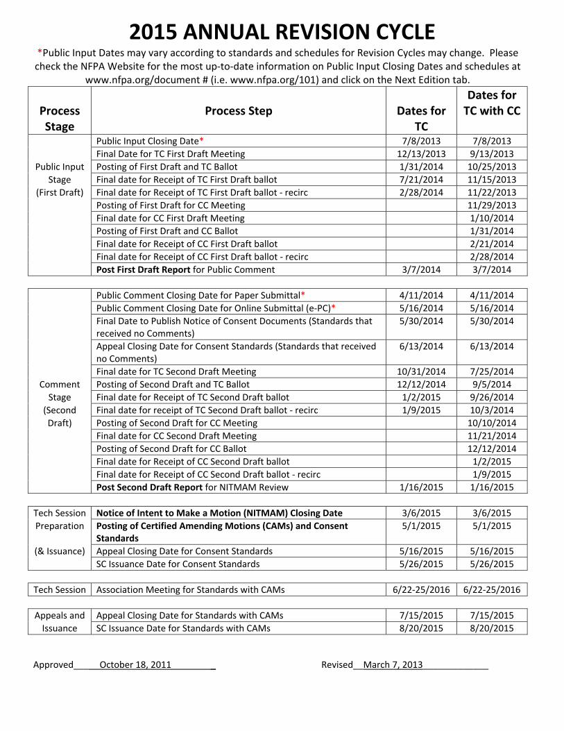
2015 ANNUAL REVISION CYCLE *Public Input Dates may vary according to standards and schedules for Revision Cycles may change. Please check the NFPA Website for the most up‐to‐date information on Public Input Closing Dates and schedules at
www.nfpa.org/document # (i.e. www.nfpa.org/101) and click on the Next Edition tab.
Process Stage
Process Step
Dates for
TC
Dates forTC with CC
Public Input Closing Date* 7/8/2013 7/8/2013
Final Date for TC First Draft Meeting 12/13/2013 9/13/2013
Public Input Posting of First Draft and TC Ballot 1/31/2014 10/25/2013
Stage Final date for Receipt of TC First Draft ballot 7/21/2014 11/15/2013
(First Draft) Final date for Receipt of TC First Draft ballot ‐ recirc 2/28/2014 11/22/2013
Posting of First Draft for CC Meeting 11/29/2013
Final date for CC First Draft Meeting 1/10/2014
Posting of First Draft and CC Ballot 1/31/2014
Final date for Receipt of CC First Draft ballot 2/21/2014
Final date for Receipt of CC First Draft ballot ‐ recirc 2/28/2014
Post First Draft Report for Public Comment 3/7/2014 3/7/2014
Public Comment Closing Date for Paper Submittal* 4/11/2014 4/11/2014
Public Comment Closing Date for Online Submittal (e‐PC)* 5/16/2014 5/16/2014
Final Date to Publish Notice of Consent Documents (Standards that received no Comments)
5/30/2014 5/30/2014
Appeal Closing Date for Consent Standards (Standards that received no Comments)
6/13/2014 6/13/2014
Final date for TC Second Draft Meeting 10/31/2014 7/25/2014
Comment Posting of Second Draft and TC Ballot 12/12/2014 9/5/2014
Stage Final date for Receipt of TC Second Draft ballot 1/2/2015 9/26/2014
(Second Final date for receipt of TC Second Draft ballot ‐ recirc 1/9/2015 10/3/2014
Draft) Posting of Second Draft for CC Meeting 10/10/2014
Final date for CC Second Draft Meeting 11/21/2014
Posting of Second Draft for CC Ballot 12/12/2014
Final date for Receipt of CC Second Draft ballot 1/2/2015
Final date for Receipt of CC Second Draft ballot ‐ recirc 1/9/2015
Post Second Draft Report for NITMAM Review 1/16/2015 1/16/2015
Tech Session Notice of Intent to Make a Motion (NITMAM) Closing Date 3/6/2015 3/6/2015
Preparation Posting of Certified Amending Motions (CAMs) and Consent Standards
5/1/2015 5/1/2015
(& Issuance) Appeal Closing Date for Consent Standards 5/16/2015 5/16/2015
SC Issuance Date for Consent Standards 5/26/2015 5/26/2015
Tech Session Association Meeting for Standards with CAMs 6/22‐25/2016 6/22‐25/2016
Appeals and Appeal Closing Date for Standards with CAMs 7/15/2015 7/15/2015
Issuance SC Issuance Date for Standards with CAMs 8/20/2015 8/20/2015
Approved___ October 18, 2011 _ Revised__March 7, 2013_____________

PART 6 –
PUBLIC COMMENTS

Public Comment No. 16-NFPA 13D-2014 [ Section No. 2.3.3 ]
2.3.3 ASTM Publications.
ASTM International, 100 Barr Harbor Drive, P.O. Box C700, West Conshohocken, PA 19428-2959.
ASTM A 53 A53/A53M , Standard Specification for Pipe, Steel, Black and Hot-Dipped, Zinc-Coated, Weldedand Seamless, 2010 2012 .
ASTM A 135 A135/A135M , Standard Specification for Electric-Resistance-Welded Steel Pipe, 2009(2014) .
ASTM A 234 A234/A234M , Standard Specification for Piping Fittings of Wrought Carbon Steel and AlloySteel for Moderate and High Temperature Service, 2010 2013 e1 .
ASTM A 795 A795/A795M , Standard Specification for Black and Hot-Dipped Zinc-Coated (Galvanized)Welded and Seamless Steel Pipe for Fire Protection Use, 2008 2013 .
ASTM B 32 B32 , Standard Specification for Solder Metal, 2008.
ASTM B 43 B43 , Standard Specification for Seamless Red Brass Pipe, 2009.
ASTM B 75 B75/B75M , Standard Specification for Seamless Copper Tube, 2002 2011 .
ASTM B 88 B88 , Standard Specification for Seamless Copper Water Tube, 2009.
ASTM B 251 B251 , Standard Specification for General Requirements for Wrought Seamless Copper andCopper-Alloy Tube, 2010.
ASTM B 813 B813 , Standard Specification for Liquid and Paste Fluxes for Soldering Applications ofCopper and Copper-Alloy Tube, 2010.
ASTM B 828 B828 , Standard Practice for Making Capillary Joints by Soldering of Copper and Copper AlloyTube and Fittings, 2002 (2010) .
ASTM F 437 F437 , Standard Specification for Threaded Chlorinated Poly (Vinyl Chloride) (CPVC) PlasticPipe Fittings, Schedule 80, 2009.
ASTM F 438 F438 , Standard Specification for Socket-Type Chlorinated Poly (Vinyl Chloride) (CPVC)Plastic Pipe Fittings, Schedule 40, 2009.
ASTM F 439 F439 , Standard Specification for Socket-Type Chlorinated Poly (Vinyl Chloride) (CPVC)Plastic Pipe Fittings, Schedule 80, 2009 2013 .
ASTM F 442 F442/F442M , Standard Specification for Chlorinated Poly (Vinyl Chloride) (CPVC) PlasticPipe (SDR-PR), 2009 2013 e1 .
ASTM F 876 F876 , Standard Specification for Crosslinked Polyethylene (PEX) Tubing, 2011 2013a .
Statement of Problem and Substantiation for Public Comment
standards date updates
Related Item
First Revision No. 1-NFPA 13D-2013 [Section No. 8.3.3]
Submitter Information Verification
Submitter Full Name: Marcelo Hirschler
Organization: GBH International
Street Address:
City:
State:
Zip:
National Fire Protection Association Report http://submittals.nfpa.org/TerraViewWeb/ContentFetcher?commentPara...
1 of 50 5/21/2014 9:34 AM

Submittal Date: Sun Apr 27 17:34:28 EDT 2014
National Fire Protection Association Report http://submittals.nfpa.org/TerraViewWeb/ContentFetcher?commentPara...
2 of 50 5/21/2014 9:34 AM

Public Comment No. 29-NFPA 13D-2014 [ Section No. 2.3.3 ]
2.3.3 ASTM Publications.
ASTM International, 100 Barr Harbor Drive, P.O. Box C700, West Conshohocken, PA 19428-2959.
ASTM A 53/A 53M , Standard Specification for Pipe, Steel, Black and Hot-Dipped, Zinc-Coated, Weldedand Seamless, 2010 2012 .
ASTM A 135/A 135M , Standard Specification for Electric-Resistance-Welded Steel Pipe, 2009.
ASTM A 234/A234M , Standard Specification for Piping Fittings of Wrought Carbon Steel and Alloy Steel forModerate and High Temperature Service, 2010 2013e1 .
ASTM A 795/A 795M , Standard Specification for Black and Hot-Dipped Zinc-Coated (Galvanized) Weldedand Seamless Steel Pipe for Fire Protection Use, 2008.
ASTM B 32, Standard Specification for Solder Metal, 2008 2013 .
ASTM B 43, Standard Specification for Seamless Red Brass Pipe, 2009.
ASTM B 75, Standard Specification for Seamless Copper Tube, 2002 2011 .
ASTM B 88, Standard Specification for Seamless Copper Water Tube, 2009.
ASTM B 251, Standard Specification for General Requirements for Wrought Seamless Copper andCopper-Alloy Tube, 2010.
ASTM B 813, Standard Specification for Liquid and Paste Fluxes for Soldering Applications of Copper andCopper-Alloy Tube, 2010.
ASTM B 828, Standard Practice for Making Capillary Joints by Soldering of Copper and Copper Alloy Tubeand Fittings, 2002 02(2010) .
ASTM F 437, Standard Specification for Threaded Chlorinated Poly (Vinyl Chloride) (CPVC) Plastic PipeFittings, Schedule 80, 2009.
ASTM F 438, Standard Specification for Socket-Type Chlorinated Poly (Vinyl Chloride) (CPVC) Plastic PipeFittings, Schedule 40, 2009.
ASTM F 439, Standard Specification for Socket-Type Chlorinated Poly (Vinyl Chloride) (CPVC) Plastic PipeFittings, Schedule 80, 2009 2013 .
ASTM F 442, Standard Specification for Chlorinated Poly (Vinyl Chloride) (CPVC) Plastic Pipe (SDR-PR),2009 2013e1 .
ASTM F 876, Standard Specification for Crosslinked Polyethylene (PEX) Tubing, 2011 2013a .
Statement of Problem and Substantiation for Public Comment
Update year dates for standards
Related Item
First Revision No. 1-NFPA 13D-2013 [Section No. 8.3.3]
Submitter Information Verification
Submitter Full Name: Steve Mawn
Organization: ASTM International
Street Address:
City:
State:
Zip:
Submittal Date: Thu May 15 14:58:00 EDT 2014
National Fire Protection Association Report http://submittals.nfpa.org/TerraViewWeb/ContentFetcher?commentPara...
3 of 50 5/21/2014 9:34 AM
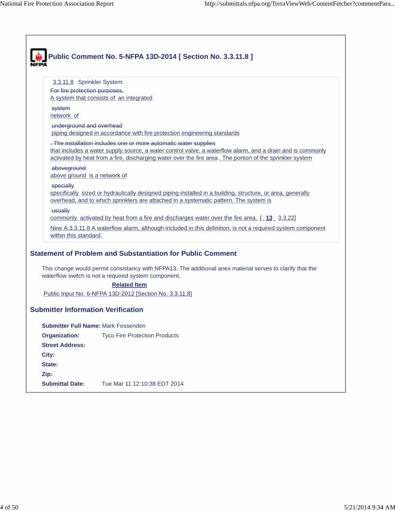
Public Comment No. 5-NFPA 13D-2014 [ Section No. 3.3.11.8 ]
3.3.11.8 Sprinkler System.
For fire protection purposes,A system that consists of an integrated
systemnetwork of
underground and overheadpiping designed in accordance with fire protection engineering standards
. The installation includes one or more automatic water suppliesthat includes a water supply source, a water control valve, a waterflow alarm, and a drain and is commonlyactivated by heat from a fire, discharging water over the fire area . The portion of the sprinkler system
abovegroundabove ground is a network of
speciallyspecifically sized or hydraulically designed piping installed in a building, structure, or area, generallyoverhead, and to which sprinklers are attached in a systematic pattern. The system is
usuallycommonly activated by heat from a fire and discharges water over the fire area. [ 13 3.3.22]
New A.3.3.11.8 A waterflow alarm, although included in this definition, is not a required system componentwithin this standard.
Statement of Problem and Substantiation for Public Comment
This change would permit consistancy with NFPA13. The additional anex material serves to clarify that the waterflow switch is not a required system component.
Related Item
Public Input No. 6-NFPA 13D-2012 [Section No. 3.3.11.8]
Submitter Information Verification
Submitter Full Name: Mark Fessenden
Organization: Tyco Fire Protection Products
Street Address:
City:
State:
Zip:
Submittal Date: Tue Mar 11 12:10:38 EDT 2014
National Fire Protection Association Report http://submittals.nfpa.org/TerraViewWeb/ContentFetcher?commentPara...
4 of 50 5/21/2014 9:34 AM

Public Comment No. 9-NFPA 13D-2014 [ Section No. 4.5 ]
National Fire Protection Association Report http://submittals.nfpa.org/TerraViewWeb/ContentFetcher?commentPara...
5 of 50 5/21/2014 9:34 AM

4.5 * Documentation.
National Fire Protection Association Report http://submittals.nfpa.org/TerraViewWeb/ContentFetcher?commentPara...
6 of 50 5/21/2014 9:34 AM

Documentation shall be available upon request to ensure adequate water supply, listed devices, andadequate sprinkler coverage have been addressed.
4.5 * Documentation.
Documentation shall be available upon request to ensure adequate water supply, listed devices, andadequate sprinkler coverage have been addressed.
Working Plans. Working plans shall be drawn to an indicated scale, on sheets of uniform size, with aplan of each floor, and shall show those items from the following list that pertain to the design of thesystem:
(1) Name of owner.
(2) Location, including street address.
(3) Point of compass.
(4) Full height cross section.
(5) Ceiling/roof heights and slopes not shown in the full height cross section.
(6) Location of partitions, lintels, and doorways. Lintel openings require a cross section view toindicate the area of the opening.
(7) Name and label for each area or room.
(8) For systems supplied by city mains, location and size of city main in street, and location, size, andtype of domestic line, including length to city connection, and water meter location and size. Staticand residual hydrants that were used in flow tests shall be shown. The location of the 5 gpmdomestic demand shall be indicated.
(9) Make, type, model, temperature rating, nominal K-factor, and number of each type of sprinkler,including sprinkler identification number.
(10) Pipe type and schedule of wall thickness.
(11) Nominal pipe size and cutting lengths of pipe (or center-to-center dimensions). Where typicalbranch lines prevail, it shall be necessary to size only one typical line.
(12) Location and size of riser nipples and drops.
(13) Type of fittings and joints.
(14) Type and locations of hangers, and methods of securing sprinklers when applicable.
(15) Location and size of all valves and drain pipes.
(16) Location and size of water gauges.
(17) Where the equipment is to be installed as an addition to an existing system, enough of theexisting system indicated on the plans to make all conditions clear.
(18) A summary of the hydraulics, including the static pressure, residual pressure, and flow of thewater supply, the pressure and flow demands at the point of connection to the water supply, and thepressure and flow demands at the bottom of the system riser.
(19) Hydraulic reference points shown on the plan that correspond with comparable reference pointson the hydraulic calculation sheets.
(20) Relative elevations of sprinklers, junction points, and supply or reference points.
(21) A graphic representation of the scale used on all plans.
(22) Name, address, phone number of the contractor.
(23) Where required by the AHJ, documentation of the designer credentials.
(24) Indicate by note the minimum rate of water application per sprinkler head, the maximum spacingfor each head, and the domestic demand.
(25) Information about antifreeze solution used. Indicate the type of antifreeze used, the amount ofantifreeze in the system, and information about antifreeze compatibility with the pipe.
(26) General notes as required by the AHJ.
(27) Edition year of NFPA 13D to which the sprinkler system is designed.
National Fire Protection Association Report http://submittals.nfpa.org/TerraViewWeb/ContentFetcher?commentPara...
7 of 50 5/21/2014 9:34 AM

(28) Utility plans and/or plumbing plans necessary to show connection from water supply to firesprinkler system.
Statement of Problem and Substantiation for Public Comment
The TC states that the material in A.4.5 adequately covers the materials “necessary” for documentation. We agree with the TC that the information in A.4.5 is truly “necessary” documentation for a review of a 13D submittal. Being “necessary” information, it should not be contained in the annex but should be contained in the core text. This requirement is specifically stated in the Manual of Style section 2.3.4.1 “The annexes of codes and standards shall be used for advisory text, explanatory material, and supplementary information and shall not be used for mandatory requirements.” If the requirements of A.4.5 are truly “necessary”, and we agree with the TC that they are, then the text clearly has to be mandatory in order for a “necessary” requirement to be provided by the designer and reviewed by the AHJ.
In addition, if “necessary” information is not provided as part of an initial permit submittal for an AHJ to review the sprinkler design for compliance with NFPA 13D, the TC is basically mandating that the AHJ is going to reject the first submittal of each 13D system because the “necessary” information for a review has not been submitted. This creates additional time delays and additional costs which is directly counter to the TC’s concern that of avoiding “unnecessary” costs.
Related Item
Public Input No. 32-NFPA 13D-2013 [Section No. 4.5]
Submitter Information Verification
Submitter Full Name: Bill Galloway
Organization: Southern Regional Fire Code De
Street Address:
City:
State:
Zip:
Submittal Date: Thu Apr 17 12:59:31 EDT 2014
National Fire Protection Association Report http://submittals.nfpa.org/TerraViewWeb/ContentFetcher?commentPara...
8 of 50 5/21/2014 9:34 AM
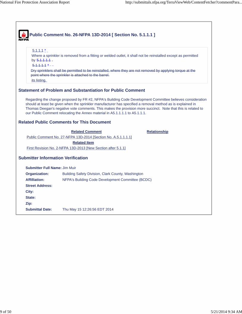
Public Comment No. 26-NFPA 13D-2014 [ Section No. 5.1.1.1 ]
5.1.1.1 *
Where a sprinkler is removed from a fitting or welded outlet, it shall not be reinstalled except as permittedby 5.1.1.1.1 .
5.1.1.1.1 *
Dry sprinklers shall be permitted to be reinstalled, where they are not removed by applying torque at thepoint where the sprinkler is attached to the barrel.
its listing.
Statement of Problem and Substantiation for Public Comment
Regarding the change proposed by FR #2, NFPA's Building Code Development Committee believes consideration should at least be given when the sprinkler manufacturer has specified a removal method as is explained in Thomas Deegan’s negative vote comments. This makes the provision more succinct. Note that this is related to our Public Comment relocating the Annex material in A5.1.1.1.1 to A5.1.1.1.
Related Public Comments for This Document
Related Comment Relationship
Public Comment No. 27-NFPA 13D-2014 [Section No. A.5.1.1.1.1]
Related Item
First Revision No. 2-NFPA 13D-2013 [New Section after 5.1.1]
Submitter Information Verification
Submitter Full Name: Jim Muir
Organization: Building Safety Division, Clark County, Washington
Affilliation: NFPA's Building Code Development Committee (BCDC)
Street Address:
City:
State:
Zip:
Submittal Date: Thu May 15 12:26:56 EDT 2014
National Fire Protection Association Report http://submittals.nfpa.org/TerraViewWeb/ContentFetcher?commentPara...
9 of 50 5/21/2014 9:34 AM

Public Comment No. 10-NFPA 13D-2014 [ Section No. 5.1.2.1 ]
5.1.2.1
Tanks, expansion tanks, gauges, pumps, hangers, waterflow detection devices, and valves shall not berequired to be listed.
Statement of Problem and Substantiation for Public Comment
Gauges are not always required but when they are utilized, should not be required to be listed.
Related Item
First Revision No. 3-NFPA 13D-2013 [Section No. 5.1.2]
Submitter Information Verification
Submitter Full Name: Peter Schwab
Organization: Wayne Automatic Fire Sprinkler
Street Address:
City:
State:
Zip:
Submittal Date: Thu Apr 17 13:12:50 EDT 2014
National Fire Protection Association Report http://submittals.nfpa.org/TerraViewWeb/ContentFetcher?commentPara...
10 of 50 5/21/2014 9:34 AM

Public Comment No. 7-NFPA 13D-2014 [ New Section after 5.2.3.1 ]
5.2.3.1.1 When pipe differing from those specified in Table 5.2.2 is to be used, it shall be installedbehind a thermal barrier of not less than 1/2 inch gypsum board unless specifically listed to beinstalled without protection.
Statement of Problem and Substantiation for Public Comment
Don’t feel that the committee statement is completely true. Fire officials need to have this additional guidance available in the Standard in order to make it more available than merely being noted in the pipe’s listing and manufacturers’ installation instructions.
Related Item
Public Input No. 24-NFPA 13D-2013 [Section No. 5.2.3 [Excluding any Sub-Sections]]
Submitter Information Verification
Submitter Full Name: John Chartier
Organization: Northeastern Regional Fire Cod
Street Address:
City:
State:
Zip:
Submittal Date: Mon Apr 07 11:56:22 EDT 2014
National Fire Protection Association Report http://submittals.nfpa.org/TerraViewWeb/ContentFetcher?commentPara...
11 of 50 5/21/2014 9:34 AM

Public Comment No. 8-NFPA 13D-2014 [ New Section after 5.3 ]
5.3* Underground Pipe.
5.3.1 Type. Any type of pipe or tube acceptable under the applicable plumbing code forunderground supply pipe shall be acceptable as an underground supply for a fire sprinkler systemwhen installed between the point of connection and the system riser.
5.3.2 Depth of Cover.
5.3.2.1 Except where specified otherwise by the applicable plumbing code, the top of the pipe shallbe buried not less than 1 ft (0.3 m) below the frost line for the locality. In those locations wherefrost is not a factor, the depth of cover shall be not less than 2½ ft (0.8 m) to prevent mechanicaldamage.
5.3.2 .2 The depth of cover over water pipes shall be determined by the maximum depth of frostpenetration in the locality where the pipe is laid. The depth of cover shall be measured from the topof the pipe to finished grade, and due consideration shall always be given to future or final gradeand nature of soil.
5.3.3 Protection Against Damage. Unless specified otherwise by the applicable plumbing code, thepipe shall be protected from mechanical and physical damage.
Statement of Problem and Substantiation for Public Comment
The text comes from NFPA 24. There are many areas in the country that do not have a plumbing code and the text would provide guidance to them. Alos do to the recent harsh winters additional quidance needs to be provided to them. Not all jurisdictions employ a plumbing code. Some adopted plumbing codes don’t address these concerns or does not address fire service mains. The proposal addresses the minimum guidelines when not otherwise addressed by the local plumbing code and recognizes a hierarchy that establishes that the local plumbing code takes precedence.
Related Item
Public Input No. 29-NFPA 13D-2013 [Section No. 5.3]
Submitter Information Verification
Submitter Full Name: John Chartier
Organization: Northeastern Regional Fire Cod
Street Address:
City:
State:
Zip:
Submittal Date: Mon Apr 07 12:01:02 EDT 2014
National Fire Protection Association Report http://submittals.nfpa.org/TerraViewWeb/ContentFetcher?commentPara...
12 of 50 5/21/2014 9:34 AM

Public Comment No. 28-NFPA 13D-2014 [ Section No. 5.3 ]
5.3 * Underground Pipe.
Any type of pipe or Pipe or tube acceptable under the applicable plumbing code for underground supplypipe shall be acceptable as an underground supply for a fire sprinkler system when installed between thepoint of connection and the system riser.
Statement of Problem and Substantiation for Public Comment
NFPA's Building Code Development Committee (BCDC) agrees with the submitter of Public Input #18 that this is editorial. The Technical Committees reason for not developing a First Revision does not make sense.
Related Item
Public Input No. 18-NFPA 13D-2013 [Section No. 5.3]
Submitter Information Verification
Submitter Full Name: Jim Muir
Organization: Building Safety Division, Clark County, Washington
Affilliation: NFPA's Building Code Development Committee (BCDC)
Street Address:
City:
State:
Zip:
Submittal Date: Thu May 15 12:56:34 EDT 2014
National Fire Protection Association Report http://submittals.nfpa.org/TerraViewWeb/ContentFetcher?commentPara...
13 of 50 5/21/2014 9:34 AM

Public Comment No. 32-NFPA 13D-2014 [ New Section after 8.2.5.6 ]
8.2.5.7
Small areas created by architectural features such as planter box windows, bay windows, and similarfeatures shall be evaluated as follows:
(1) Where no additional floor area is created by the architectural feature, no additional sprinkler protectionis required.
(2) Where additional floor area is created by an architectural feature, no additional sprinkler protection isrequired, provided all of the following conditions are met:
(a) The floor area shall not exceed 18 ft2 (1.7 m2).
(b) The floor area shall not be greater than 2 ft (0.61 m) in depth at the deepest point of thearchitectural feature to the plane of the primary wall where measured along the finished floor.
(c) The floor shall not be greater than 9 ft (2.7 m) in length where measured along the plane of theprimary wall.
(d) Measurement from the deepest point of the architectural feature to the sprinkler shall not exceedthe maximum listed spacing of the sprinkler.
(3) The hydraulic design is not required to consider the area created by the architectural feature.
Statement of Problem and Substantiation for Public Comment
This language has long been in the annex of NFPA 13D and it is clear that it is the committee's belief that additional floor area created by certain architectural features are not required to have additional sprinkler coverage. As this language is in the annex and not in the enforceable body of the standard, this intent is not consistently applied to such architectural features. Moving this language to the body of the standard would make this longstanding intent of the committee enforceable and clear that additional sprinkler protection is not required in these small areas. As these areas are not required to be included in the hydraulic design area of the systems, these areas are distinct from shadow areas. This language has been included in the body of NFPA 13R and it is not the intent that the requirements of NFPA 13D be more stringent in regards to this issue.
Related Public Comments for This Document
Related Comment Relationship
Public Comment No. 31-NFPA 13D-2014 [Section No. A.8.2.5]
Related Item
First Revision No. 15-NFPA 13D-2013 [Section No. A.8.2.5]
Submitter Information Verification
Submitter Full Name: Roland Asp
Organization: National Fire Sprinkler Association
Affilliation: NFSA E&S Committee
Street Address:
City:
State:
Zip:
Submittal Date: Fri May 16 15:10:09 EDT 2014
National Fire Protection Association Report http://submittals.nfpa.org/TerraViewWeb/ContentFetcher?commentPara...
14 of 50 5/21/2014 9:34 AM

Public Comment No. 25-NFPA 13D-2014 [ New Section after 8.2.7 ]
8.2.7.1
In closets and compartments enclosed by walls and a door, including those housing mechanicalequipment, that are smaller than 400 ft3 (11.3 m3), pendent, upright and sidewall residential sprinklersshall be permitted to be installed within 18 inches of the ceiling to avoid obstructions near the ceiling.
Additional Proposed Changes
File Name Description Approved
Computer_Modeling_of_Closet.pdf Computer modeling of closet with residential sprinklers
Statement of Problem and Substantiation for Public Comment
Small closets, especially those housing mechanical equipment, frequently contain obstructions that make it difficult to place sprinklers within 12 inches of the ceiling. Allowing residential sprinklers to be located further down would allow adequate sprinkler protection of these small closets while avoiding ceiling level obstructions such as ducts and pipes. Based upon CFAST Computer Fire Model, an analysis was performed comparing the performance of sprinklers located 6 inches down from a ceiling in a small room to the performance of sprinklers 18 inches down from the ceiling in an even smaller closet. Based upon this analysis it appears that residential sprinklers 18 inches down from the ceiling in a closet up to 400 ft3 react to a fire at least as quickly as residential sprinklers 6 inches down from a ceiling in a small room. Using equivalency concepts, residential sprinklers could be allowed to be installed within 18 inches of the ceiling in small closets. This analysis is included in this public comment.
Related Item
First Correlating Revision No. 1-NFPA 13D-2013 [Section No. 8.2.7]
Submitter Information Verification
Submitter Full Name: Roland Asp
Organization: National Fire Sprinkler Association
Affilliation: NFSA E&S Committee
Street Address:
City:
State:
Zip:
Submittal Date: Wed May 14 09:50:28 EDT 2014
National Fire Protection Association Report http://submittals.nfpa.org/TerraViewWeb/ContentFetcher?commentPara...
15 of 50 5/21/2014 9:34 AM

Computer Modeling of Closet with Residential Sprinkler 18 Inches from Ceiling
This analysis uses the CFAST Computer Fire Model to compare the performance of sprinklers 6
inches down from the ceiling in a small room to the performance of sprinklers 18 inches down
from the ceiling in an even smaller closet.
Baseline Room: 15 ft x 15 ft x 8 ft
3 sprinkler locations (see Figure 1)
o Sprinkler 1 – 4 ft from south and west walls
o Sprinkler 2 – Centered between east and west walls, 4 ft from south wall
o Sprinkler 3 – 4 inches from south and east walls
All sprinklers 6 inches from ceiling
All sprinklers RTI = 50 (metric units)
Closet: 7 ft x 7 ft x 8 ft (392 ft
3)
3 sprinkler locations (see Figure 2)
o Sprinkler 1 – 2 ft from south and west walls
o Sprinkler 2 – Centered between east and west walls, 2 ft from south wall
o Sprinkler 3 – 4 inches from south and east walls
All sprinklers 18 inches down from ceiling
All sprinklers RTI = 50 (metric units)
Fire: Fairly slow growing fire
Center of the room/closet
See Figure 3
1 2 3
Figure 1 – Baseline Room
1 2 3
Figure 2 – Closet 392 ft3

Figure 3 – Heat Release Rate for Fire
(Note that the first 600 seconds are the only
important parts of the heat release due to sprinkler activation time)
Results
The following table compares the activation time of the sprinklers in the small room to that of
the sprinklers in the even smaller closet:
Sprinkler Activation Time in
Small Room (Figure 1)
Activation Time in Closet (Figure 2)
1 510 seconds 500 seconds
2 530 seconds 500 seconds
3 510 seconds 500 seconds
Conclusions
Given this fire location and these three sprinkler locations, it would appear that residential
sprinklers 18 inches down from the ceiling in a closet up to 400 ft3 react to a fire at least as
quickly as residential sprinklers 6 inches down from a ceiling in a small room. Using
equivalency concepts, residential sprinklers could be allowed to be installed within 18 inches of
the ceiling in small closets.
Prior to making any final determination, other combinations of fire size, fire location, and
sprinkler location should be analyzed in the same manner.

Public Comment No. 11-NFPA 13D-2014 [ Section No. 8.2.7 ]
8.2.7 Closets.
In all closets and compartments, including those housing mechanical equipment, that are smaller than 400
ft3 (11.3 m3), a single sprinkler at the highest ceiling space ceiling level shall be sufficient without regard toobstructions or minimum distances to wall.
Statement of Problem and Substantiation for Public Comment
This change correlates with the language in NFPA 13R.
Related Item
First Revision No. 26-NFPA 13D-2013 [Section No. 8.2.5.1]
Submitter Information Verification
Submitter Full Name: Peter Schwab
Organization: Wayne Automatic Fire Sprinkler
Street Address:
City:
State:
Zip:
Submittal Date: Thu Apr 17 13:41:16 EDT 2014
National Fire Protection Association Report http://submittals.nfpa.org/TerraViewWeb/ContentFetcher?commentPara...
16 of 50 5/21/2014 9:34 AM
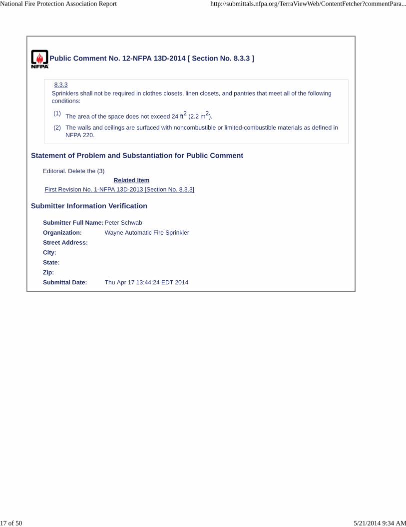
Public Comment No. 12-NFPA 13D-2014 [ Section No. 8.3.3 ]
8.3.3
Sprinklers shall not be required in clothes closets, linen closets, and pantries that meet all of the followingconditions:
(1) The area of the space does not exceed 24 ft2 (2.2 m2).
(2) The walls and ceilings are surfaced with noncombustible or limited-combustible materials as defined inNFPA 220.
Statement of Problem and Substantiation for Public Comment
Editorial. Delete the (3)
Related Item
First Revision No. 1-NFPA 13D-2013 [Section No. 8.3.3]
Submitter Information Verification
Submitter Full Name: Peter Schwab
Organization: Wayne Automatic Fire Sprinkler
Street Address:
City:
State:
Zip:
Submittal Date: Thu Apr 17 13:44:24 EDT 2014
National Fire Protection Association Report http://submittals.nfpa.org/TerraViewWeb/ContentFetcher?commentPara...
17 of 50 5/21/2014 9:34 AM

Public Comment No. 23-NFPA 13D-2014 [ Section No. 10.4.3 ]
National Fire Protection Association Report http://submittals.nfpa.org/TerraViewWeb/ContentFetcher?commentPara...
18 of 50 5/21/2014 9:34 AM

10.4.3 *
National Fire Protection Association Report http://submittals.nfpa.org/TerraViewWeb/ContentFetcher?commentPara...
19 of 50 5/21/2014 9:34 AM

Unless the pipe size is in accordance with the prescriptive pipe sizing method of 10.4.9 , pipe shall besized by hydraulic calculations in accordance with the methods described in NFPA 13, with themanufacturer's listed installation instructions, with 10.4.4 , or with the following general method forstraight-run systems connected to a city water main of at least 4 in. (102 mm) in diameter:
The system flow rate shall be established in accordance with Sections 10.1 and 10.2 , and it shall bedetermined that the flow allowed by the water meter meets or exceeds the system demand and that thetotal demand flow does not exceed the maximum flow allowed by the piping system components.
The water pressure in the street shall be determined.
Pipe sizes shall be selected.
Pressure loss for a water meter, if any, shall be determined and deducted The pipes shall be sizedusing one of the following techniques :
Table 10.4.3(a) shall be permitted to be used, even where the sprinkler demand flow exceeds the meter'srated continuous flow.
Higher pressure losses specified by the manufacturer shall be used in place of those specified in Table10.4.3(a) .
Lower pressure losses shall be permitted to be used where supporting data are provided by the metermanufacturer.
Pressure loss for elevation shall be deducted as follows:
(1) Building height above street (ft) × 0.433 = pressure loss (psi)
(2) Building height above street (m) × 0.098 = pressure loss (bar)
Pressure loss for piping within the building shall be deducted by multiplying the pressure loss associatedwith the pipe material by the total length(s) of pipe in feet (meters).
Pressure loss for valves and fittings shall be deducted as follows:
(1) The valves and fittings from the control valve to the farthest sprinkler shall be counted.
(2) The equivalent length for each valve and fitting as shown in Table 10.4.3(b) , Table 10.4.3(c) , orTable 10.4.3(d) or Table 10.4.3(e) shall be determined and the values added to obtain the totalequivalent length for each pipe size.
(3) The equivalent length for each size shall be multiplied by the pressure loss associated with the pipematerial and the values totaled.
In multilevel buildings, the steps in 10.4.3 (1) through 10.4.3 (8) shall be repeated to size piping foreach floor.
If the remaining pressure is less than the operating pressure established by the testing laboratory for thesprinkler being used, the sprinkler system shall be redesigned.
If the remaining pressure is higher than required, smaller piping shall be permitted to be used wherejustified by calculations.
The remaining piping shall be sized the same as the piping up to and including the farthest sprinklerunless smaller pipe sizes are justified by calculations.
Table 10.4.3(a) Pressure Losses in psi in Water Meters
Meter Size
(in.) Flow (gpm) 18 or less 23 26 31 39 52 5 ⁄ 8 9 14 18 26 38 * 3 ⁄ 4
7 11 14 22 35 * 1 2 3 3 4 6 10 1 1 ⁄ 2 1 1 2 2 4 7 2 1 1 1 1 2 3
For SI units, 1 gpm = 3.785 L/min; 1 in. = 25.4 mm; 1 psi = 0.0689 bar.
*Above maximum rated flow of commonly available meters.
*
* Pressure losses from the city main to the inside control valve shall be deducted by multiplying thepressure loss associated with the pipe material by the total length(s) of pipe in feet (meters).
National Fire Protection Association Report http://submittals.nfpa.org/TerraViewWeb/ContentFetcher?commentPara...
20 of 50 5/21/2014 9:34 AM

Table 10.4.3(b) Equivalent Length in Feet of Fittings and Valves for Schedule 40 Steel Pipe
Diameter
(in.) 45 Degree Elbow 90 Degree Elbow Long- Radius Elbow Tee or Cross (flow turned 90 degrees) Tee orCross (flow straight through) Gate Valve Angle Valve Globe Valve Globe “Y” Pattern Valve Cock
Valve Check Valve 1 1 2 2 5 2 0 12 28 15 4 5 1 1 ⁄ 4 1 3 2 6 2 0 15 35 18 5 7 1 1 ⁄ 22 4 2 8 3 0 18 43 22 6 9 2 2 5 3 10 3 1 24 57 28 7 11
For SI units, 1 in. = 25.4 mm; 1 ft = 0.3048 m.
Table 10.4.3(c) Equivalent Length in Feet of Fittings and Valves for Type K Copper Tube
Diameter (in.) 45 Degree Elbow 90 Degree Elbow Long-
Radius Elbow Tee or Cross (flow turned 90 degrees) Tee or Cross (flow straight through) Gate Valve Angle
Valve Globe Valve Globe “Y” Pattern Valve Cock Valve Check Valve 3 ⁄ 4 0 1 0 3 1 0 7 14 7 2 0 1
1 2 2 6 2 0 14 33 18 5 6 1 1 ⁄ 4 1 3 2 5 2 0 14 32 16 5 6 1 1 ⁄ 2 2 4 2 8 3 0 18 43 22 6 9 22 6 3 12 4 1 28 66 33 8 13
For SI units, 1 in. = 25.4 mm; 1 ft = 0.3048 m.
Table 10.4.3(d) Equivalent Length in Feet of Fittings and Valves for Type L Copper Tube
Diameter (in.) 45 Degree Elbow 90 Degree Elbow Long- Radius Elbow Tee or Cross (flow turned 90degrees) Tee or Cross (flow straight through) Gate Valve Angle Valve Globe Valve Globe “Y” Pattern
Valve Cock Valve Check Valve 3 ⁄ 4 0 2 0 4 1 0 8 18 10 3 0 1 1 3 3 7 2 0 16 38 20 5 7 1 1 ⁄ 4
1 3 2 6 2 0 15 35 18 5 7 1 1 ⁄ 2 2 4 2 9 3 0 20 47 24 7 10 2 2 6 4 12 4 1 30 71 35 9 14
For SI units, 1 in. = 25.4 mm; 1 ft = 0.3048 m.
Table 10.4.3(e) Equivalent Length in Feet of Fittings and Valves for Type M Copper Tube
Diameter (in.) 45 Degree Elbow 90 Degree Elbow Long- Radius Elbow Tee or Cross (flow turned 90degrees) Tee or Cross (flow straight through) Gate Valve Angle Valve Globe Valve Globe “Y” Pattern
Valve Cock Valve Check Valve 3 ⁄ 4 0 2 0 4 1 0 10 21 11 3 0 1 2 3 3 8 3 0 19 43 23 6 8 1 1 ⁄ 4
1 3 2 7 2 0 16 38 20 5 8 1 1 ⁄ 2 2 5 2 9 3 0 21 50 26 7 11 2 3 7 4 13 5 1 32 75 37 9 14
For SI units, 1 in. = 25.4 mm; 1 ft = 0.3048 m.
(1) The simplified calculation method of 10.4.4, which can only be used for connections to a city watermain of at least 4 inches (102mm) in diameter.
(2) The prescritive pipe sizing method of 10.4.9.
(3) The hydraulic calculation procedure for NFPA 13.
(4) The manufacturers listed intallation instructions.
Statement of Problem and Substantiation for Public Comment
Section 10.4.3, as written is confusing and not "user friendly". This public comment seeks to simplify and clarify the acceptable methods for sizing sprinkler pipes for NFPA 13D systems. This comment's does not change the existing requirements of this section, but instead changes the requirements from paragraph form to a list form for ease of interpretation. The 12 step general method originally included in section 10.4.3 has been retained but renumbered as section 10.4.4.
Related Public Comments for This Document
Related Comment Relationship
Public Comment No. 19-NFPA 13D-2014 [Section No. 10.4.4]
Related Item
First Revision No. 13-NFPA 13D-2013 [Section No. 10.4.3]
Submitter Information Verification
Submitter Full Name: Roland Asp
National Fire Protection Association Report http://submittals.nfpa.org/TerraViewWeb/ContentFetcher?commentPara...
21 of 50 5/21/2014 9:34 AM

Organization: National Fire Sprinkler Association
Affilliation: NFSA E&S Committee
Street Address:
City:
State:
Zip:
Submittal Date: Mon May 12 15:06:08 EDT 2014
National Fire Protection Association Report http://submittals.nfpa.org/TerraViewWeb/ContentFetcher?commentPara...
22 of 50 5/21/2014 9:34 AM

Public Comment No. 19-NFPA 13D-2014 [ Section No. 10.4.4 ]
National Fire Protection Association Report http://submittals.nfpa.org/TerraViewWeb/ContentFetcher?commentPara...
23 of 50 5/21/2014 9:34 AM

10.4.4
Smaller pipe sizes than those determined by 10.4.3 shall be permitted where justified by calculations forsystems connected to city water mains of at least 4 in. (102 mm) in diameter.
* General Pipe Sizing Method
The following is the general pipe sizing method for straight-run systems connected to a city water main ofat least 4 in. (102 mm) in diameter as per 10.4.3 (1):
National Fire Protection Association Report http://submittals.nfpa.org/TerraViewWeb/ContentFetcher?commentPara...
24 of 50 5/21/2014 9:34 AM

(1) The system flow rate shall be established in accordance with Sections 10.1 and 10.2, and it shall bedetermined that the flow allowed by the water meter meets or exceeds the system demand and thatthe total demand flow does not exceed the maximum flow allowed by the piping system components.
(2) The water pressure in the street shall be determined.
(3) Pipe sizes shall be selected.
(4) *Pressure loss for a water meter, if any, shall be determined and deducted using one of the following:
(5) Table 10.4.4(a) shall be permitted to be used, even where the sprinkler demand flow exceedsthe meter's rated continuous flow.
(6) Higher pressure losses specified by the manufacturer shall be used in place of those specifiedin Table 10.4.4(a).
(7) Lower pressure losses shall be permitted to be used where supporting data are provided by themeter manufacturer.
(8) Pressure loss for elevation shall be deducted as follows:
(9) Building height above street (ft) × 0.433 = pressure loss (psi)
(10) Building height above street (m) × 0.098 = pressure loss (bar)
(11) *Pressure losses from the city main to the inside control valve shall be deducted by multiplying thepressure loss associated with the pipe material by the total length(s) of pipe in feet (meters).
(12) Pressure loss for piping within the building shall be deducted by multiplying the pressure lossassociated with the pipe material by the total length(s) of pipe in feet (meters).
(13) Pressure loss for valves and fittings shall be deducted as follows:
(14) The valves and fittings from the control valve to the farthest sprinkler shall be counted.
(15) The equivalent length for each valve and fitting as shown in Table 10.4.4(b), Table 10.4.4(c), orTable 10.4.4(d) or Table 10.4.4(e) shall be determined and the values added to obtain the totalequivalent length for each pipe size.
(16) The equivalent length for each size shall be multiplied by the pressure loss associated with thepipe material and the values totaled.
(17) In multilevel buildings, the steps in 10.4.4(1) through 10.4.4(8) shall be repeated to size piping foreach floor.
(18) If the remaining pressure is less than the operating pressure established by the testing laboratory forthe sprinkler being used, the sprinkler system shall be redesigned.
(19) If the remaining pressure is higher than required, smaller piping shall be permitted to be used wherejustified by calculations.
(20) The remaining piping shall be sized the same as the piping up to and including the farthest sprinklerunless smaller pipe sizes are justified by calculations.
Table 10.4.4(a) Pressure Losses in psi in Water Meters
Meter Size
(in.)
Flow (gpm)
18 or less 23 26 31 39 52
5 ⁄ 8 9 14 18 26 38 *
3 ⁄ 4 7 11 14 22 35 *
1 2 3 3 4 6 10
1 1 ⁄ 2 1 1 2 2 4 7
National Fire Protection Association Report http://submittals.nfpa.org/TerraViewWeb/ContentFetcher?commentPara...
25 of 50 5/21/2014 9:34 AM
Meter Size
(in.)
Flow (gpm)
18 or less 23 26 31 39 52
2 1 1 1 1 2 3
For SI units, 1 gpm = 3.785 L/min; 1 in. = 25.4 mm; 1 psi = 0.0689 bar.
*Above maximum rated flow of commonly available meters.
Table 10.4.4(b) Equivalent Length in Feet of Fittings and Valves forSchedule 40 Steel Pipe
Diameter
(in.)
45DegreeElbow
90DegreeElbow
Long-RadiusElbow
Tee orCross(flow
turned90
degrees)
Tee orCross(flow
straightthrough)
GateValve Angle
ValveGlobeValve
Globe“Y”
PatternValve
CockValve Chec
Valve
1 1 2 2 5 2 0 12 28 15 4 5
1 1 ⁄ 4 1 3 2 6 2 0 15 35 18 5 7
1 1 ⁄ 2 2 4 2 8 3 0 18 43 22 6 9
2 2 5 3 10 3 1 24 57 28 7 11
For SI units, 1 in. = 25.4 mm; 1 ft = 0.3048 m.
Table 10.4.4(c) Equivalent Length in Feet of Fittings and Valves for Type KCopper Tube
Diameter(in.)
45DegreeElbow
90DegreeElbow
Long-
.
RadiusElbow
Tee orCross(flow
turned90
degrees)
Tee orCross(flow
straightthrough)
GateValve Angle
ValveGlobeValve
Globe“Y”
PatternValve
CockValve Chec
Valve
3 ⁄ 4 0 1 0 3 1 0 7 14 7 2 0
1 1 2 2 6 2 0 14 33 18 5 6
1 1 ⁄ 4 1 3 2 5 2 0 14 32 16 5 6
1 1 ⁄ 2 2 4 2 8 3 0 18 43 22 6 9
2 2 6 3 12 4 1 28 66 33 8 13
For SI units, 1 in. = 25.4 mm; 1 ft = 0.3048 m.
Table 10.4.4(d) Equivalent Length in Feet of Fittings and Valves for Type LCopper Tube
Diameter(in.)
45DegreeElbow
90DegreeElbow
Long-RadiusElbow
Tee orCross(flow
turned90
degrees)
Tee orCross(flow
straightthrough)
GateValve Angle
ValveGlobeValve
Globe“Y”
PatternValve
CockValve Check
Valve
3 ⁄ 4 0 2 0 4 1 0 8 18 10 3 0
1 1 3 3 7 2 0 16 38 20 5 7
1 1 ⁄ 4 1 3 2 6 2 0 15 35 18 5 7
National Fire Protection Association Report http://submittals.nfpa.org/TerraViewWeb/ContentFetcher?commentPara...
26 of 50 5/21/2014 9:34 AM

Diameter(in.)
45DegreeElbow
90DegreeElbow
Long-RadiusElbow
Tee orCross(flow
turned90
degrees)
Tee orCross(flow
straightthrough)
GateValve Angle
ValveGlobeValve
Globe“Y”
PatternValve
CockValve Check
Valve
1 1 ⁄ 2 2 4 2 9 3 0 20 47 24 7 10
2 2 6 4 12 4 1 30 71 35 9 14
For SI units, 1 in. = 25.4 mm; 1 ft = 0.3048 m.
Table 10.4.4(e) Equivalent Length in Feet of Fittings and Valves for Type MCopper Tube
Diameter(in.)
45DegreeElbow
90DegreeElbow
Long-RadiusElbow
Tee orCross(flow
turned90
degrees)
Tee orCross(flow
straightthrough)
GateValve Angle
ValveGlobeValve
Globe“Y”
PatternValve
CockValve Check
Valve
3 ⁄ 4 0 2 0 4 1 0 10 21 11 3 0
1 2 3 3 8 3 0 19 43 23 6 8
1 1 ⁄ 4 1 3 2 7 2 0 16 38 20 5 8
1 1 ⁄ 2 2 5 2 9 3 0 21 50 26 7 11
2 3 7 4 13 5 1 32 75 37 9 14
For SI units, 1 in. = 25.4 mm; 1 ft = 0.3048 m.
Statement of Problem and Substantiation for Public Comment
The general method of pipe sizing has been moved from section 10.4.3 to 10..4.4 to correlate with Public Comment No. 20. The wording and method itself remains unchanged.
Related Public Comments for This Document
Related Comment Relationship
Public Comment No. 21-NFPA 13D-2014 [Section No. A.10.4.3]
Related Item
First Revision No. 13-NFPA 13D-2013 [Section No. 10.4.3]
Submitter Information Verification
Submitter Full Name: Roland Asp
Organization: National Fire Sprinkler Association
Affilliation: NFSA E&S Committee
Street Address:
City:
State:
Zip:
Submittal Date: Mon May 12 08:31:25 EDT 2014
National Fire Protection Association Report http://submittals.nfpa.org/TerraViewWeb/ContentFetcher?commentPara...
27 of 50 5/21/2014 9:34 AM

Public Comment No. 24-NFPA 13D-2014 [ Section No. 12.3.2 ]
12.3.2
Any sprinkler that is operated, damaged, corroded, covered with foreign materials, or showing signs ofleakage shall be replaced with a new listed sprinkler having the same performance characteristics as theoriginal equipment.
12.3.2.1 *
Where replacing residential sprinklers manufactured prior to 2003 and that are no longer available from
the manufacturer and are installed using a design density less than 0.05 gpm/ft2 (204 mm/min), aresidential sprinkler with an equivalent K-factor (± 5%) shall be permitted to be used provided the currentlylisted coverage area for the replacement sprinkler is not exceeded.
Statement of Problem and Substantiation for Public Comment
It is preferred to replace existing sprinklers with the same model when it is available so that the systems continue to operate as it was designed. This proposal was developed by the UL/FM/NFSA Standards Review Committee.
Related Item
First Revision No. 23-NFPA 13D-2013 [Section No. 12.3.2]
Submitter Information Verification
Submitter Full Name: Victoria Valentine
Organization: National Fire Sprinkler Assoc
Affilliation: UL/FM/NFSA Standards Review Committee
Street Address:
City:
State:
Zip:
Submittal Date: Wed May 14 09:42:39 EDT 2014
National Fire Protection Association Report http://submittals.nfpa.org/TerraViewWeb/ContentFetcher?commentPara...
28 of 50 5/21/2014 9:34 AM

Public Comment No. 1-NFPA 13D-2014 [ Section No. 12.3.2.1 ]
12.3.2.1 *
Where
replacingresidential sprinklers
manufactured prior to 2003 and installed using a design density less than 0.05 gpm/ft 2 (204 mm/min), aresidential sprinkler with an equivalent K-factor (± 5%) shall be permitted to be used provided the currentlylisted coverage area for the replacement sprinkler is not exceededrequire replacement and the same model of residential sprinkler is no longer available, replacementresidential sprinklers shall either have a consistent hydraulic demand with the original residential sprinklersor calculations shall be provided to demonstrate that system supply meets the demand of the replacementsprinklers .
Statement of Problem and Substantiation for Public Comment
The proposed language would allow the use of replacement sprinklers with hydraulic demands that may exceed the available system supply. If an equivalent replacement sprinkler is not available, then calculations should be performed that prove the system can support the replacement residential sprinklers.
Related Item
First Revision No. 23-NFPA 13D-2013 [Section No. 12.3.2]
Submitter Information Verification
Submitter Full Name: Mark Fessenden
Organization: Tyco Fire Protection Products
Street Address:
City:
State:
Zip:
Submittal Date: Tue Mar 11 10:56:57 EDT 2014
National Fire Protection Association Report http://submittals.nfpa.org/TerraViewWeb/ContentFetcher?commentPara...
29 of 50 5/21/2014 9:34 AM

Public Comment No. 13-NFPA 13D-2014 [ Section No. 12.3.2.1 ]
12.3.2.1 *
Where replacing residential sprinklers manufactured prior to 2003 and , installed using a design density
less than 0.05 gpm/ft2 (204 mm/min), a and that are no longer available from the manufacturer, aresidential sprinkler with an equivalent K-factor (± 5%) shall be permitted to be used provided the currentlylisted coverage area for the replacement sprinkler is not exceeded.
Statement of Problem and Substantiation for Public Comment
The first option should be to use the manufacturer's replacement sprinkler when it is available.
Related Item
First Revision No. 23-NFPA 13D-2013 [Section No. 12.3.2]
Submitter Information Verification
Submitter Full Name: Peter Schwab
Organization: Wayne Automatic Fire Sprinkler
Street Address:
City:
State:
Zip:
Submittal Date: Thu Apr 17 13:48:45 EDT 2014
National Fire Protection Association Report http://submittals.nfpa.org/TerraViewWeb/ContentFetcher?commentPara...
30 of 50 5/21/2014 9:34 AM

Public Comment No. 17-NFPA 13D-2014 [ Section No. 12.3.2.1 ]
12.3.2.1 *
Where replacing residential sprinklers manufactured prior to 2003 and installed using a design density less
than 0.05 gpm/ft2 (204 mm/min), and that are no longer available from the manufacturer, a residentialsprinkler with an equivalent K-factor (± 5%) shall be permitted to be used provided the currently listedcoverage area for the replacement sprinkler is not exceeded.
Statement of Problem and Substantiation for Public Comment
This section would allow residential sprinklers installed to a design density of less then 0.05 gpm/ft2 to be replaced with a replacement sprinkler with an equivalent k-factor. As stated in A.12.3.2.1, the flow and pressure available to the replacement sprinkler might be less than its current flow and pressure requirement. If the sprinkler to be replaced is still available from the manufacturer, that sprinkler should be used as the replacement to ensure, where possible, that the original criteria continues to be met.
Related Item
First Revision No. 23-NFPA 13D-2013 [Section No. 12.3.2]
Submitter Information Verification
Submitter Full Name: Roland Asp
Organization: National Fire Sprinkler Association
Affilliation: NFSA E&S Committee
Street Address:
City:
State:
Zip:
Submittal Date: Thu May 01 10:20:28 EDT 2014
National Fire Protection Association Report http://submittals.nfpa.org/TerraViewWeb/ContentFetcher?commentPara...
31 of 50 5/21/2014 9:34 AM

Public Comment No. 30-NFPA 13D-2014 [ Section No. 12.3.2.1 ]
12.3.2.1 *
Where replacing residential sprinklers manufactured prior to 2003 that are no longer available from the
manufacturer and are installed using a design density less than 0.05 gpm/ft2 (204 mm/min), a residentialsprinkler with an equivalent K-factor (± 5%) shall be permitted to be used provided the currently listedcoverage area for the replacement sprinkler is not exceeded.
Statement of Problem and Substantiation for Public Comment
It is preferred to replace existing sprinklers with the same Model when available so that sprinkler systems continue to operate in accordance with the design intent.
Related Item
First Revision No. 23-NFPA 13D-2013 [Section No. 12.3.2]
Submitter Information Verification
Submitter Full Name: Scott Franson
Organization: The Viking Corporation
Affilliation: UL/FM/NFSA Committee
Street Address:
City:
State:
Zip:
Submittal Date: Fri May 16 14:15:30 EDT 2014
National Fire Protection Association Report http://submittals.nfpa.org/TerraViewWeb/ContentFetcher?commentPara...
32 of 50 5/21/2014 9:34 AM

Public Comment No. 6-NFPA 13D-2014 [ Sections A.4.5, A.5.1.1 ]
Sections A.4.5, A.5.1.1
National Fire Protection Association Report http://submittals.nfpa.org/TerraViewWeb/ContentFetcher?commentPara...
33 of 50 5/21/2014 9:34 AM

A.4.5
National Fire Protection Association Report http://submittals.nfpa.org/TerraViewWeb/ContentFetcher?commentPara...
34 of 50 5/21/2014 9:34 AM
A scaled drawing where required should show the following:
(1) Address (if known)
(2) Size and type of domestic line, including length to city connection
(3) Water meter size
(4) Current static water pressure
(5) Interior walls
(6) Model, manufacturer, temperature, orifice size, and spacing requirements of sprinklers
(7) Type of pipe
(8) Hanger spacing requirement per the pipe manufacturer
(9) Riser detail
(10) Installing contractor information
(11) Preliminary hydraulic calculations
(12) Name of owner.Location, including street address.
Point of compass.
Full height cross section.
Ceiling/roof heights and slopes not shown in the full height cross section.
Location of partitions, lintels, and doorways. Lintel openings require a cross section view to indicatethe area of the opening.
Name and label for each area or room.
For systems supplied by city mains, location and size of city main in street, and location, size, andtype of domestic line, including length to city connection, and water meter location and size. Staticand residual hydrants that were used in flow tests shall be shown. The location of the 5 gpm domesticdemand shall be indicated.
Make, type, model, temperature rating, nominal K-factor, and number of each type of sprinkler,including sprinkler identification number.
Pipe type and schedule of wall thickness.
Nominal pipe size and cutting lengths of pipe (or center-to-center dimensions). Where typical branchlines prevail, it shall be necessary to size only one typical line.
Location and size of riser nipples and drops.
Type of fittings and joints.
Type and locations of hangers, and methods of securing sprinklers when applicable.
Location and size of all valves and drain pipes.
Location and size of water gauges.
Where the equipment is to be installed as an addition to an existing system, enough of the existingsystem indicated on the plans to make all conditions clear.
A summary of the hydraulics, including the static pressure, residual pressure, and flow of the watersupply, the pressure and flow demands at the point of connection to the water supply, and thepressure and flow demands at the bottom of the system riser .
Hydraulic reference points shown on the plan that correspond with comparable reference points onthe hydraulic calculation sheets.
Relative elevations of sprinklers, junction points, and supply or reference points.
A graphic representation of the scale used on all plans.
Name, address, phone number of the contractor.
Where required by the AHJ, documentation of the designer credentials.
Indicate by note the minimum rate of water application per sprinkler head, the maximum spacing foreach head, and the domestic demand.
National Fire Protection Association Report http://submittals.nfpa.org/TerraViewWeb/ContentFetcher?commentPara...
35 of 50 5/21/2014 9:34 AM
Information about antifreeze solution used. Indicate the type of antifreeze used, the amount ofantifreeze in the system, and information about antifreeze compatibility with the pipe.
General notes as required by the AHJ.
Edition year of NFPA 13D to which the sprinkler system is designed.
Utility plans and/or plumbing plans necessary to show connection from water supply to fire sprinklersystem.
A. 5.1.1
Where fused sprinklers are replaced by the owner, fire department, or others, care should be taken toensure that the replacement sprinkler has the same operating characteristics.
Statement of Problem and Substantiation for Public Comment
The list was expanded in hte annex to give quidance to the users and AHJ's on what may be needed to conduct a plan reviews. During design review we need to ask these questions and adding them to the list reduces the number of times we need to go back and forth between plan review and installer. Adding them to the list will reduce plan review times and assist the user and installer.
Related Item
Public Input No. 32-NFPA 13D-2013 [Section No. 4.5]
Submitter Information Verification
Submitter Full Name: Kelly Nicolello
Organization: Western Regional Fire Code Dev
Street Address:
City:
State:
Zip:
Submittal Date: Tue Apr 01 18:05:47 EDT 2014
National Fire Protection Association Report http://submittals.nfpa.org/TerraViewWeb/ContentFetcher?commentPara...
36 of 50 5/21/2014 9:34 AM

Public Comment No. 27-NFPA 13D-2014 [ Section No. A.5.1.1.1.1 ]
A.5.1.1.1.1
Provided dry sprinklers are removed by utilizing a pipe wrench on the barrel, where permitted by themanufacturer, they can be reinstalled. If a dry sprinkler is removed by utilizing the sprinkler wrench on theboss base of the sprinkler, the dry sprinkler should not be reinstalled.
Statement of Problem and Substantiation for Public Comment
This Public Comment is related to the NFPA Building Code Development Committee's (BCDC) Public Comment #26, which proposes deletion of section 5.1.1.1.1. The BCDC felt the annex material was valuable and should be moved to A5.1.1.1.
Related Public Comments for This Document
Related Comment Relationship
Public Comment No. 26-NFPA 13D-2014 [Section No. 5.1.1.1]
Related Item
First Revision No. 2-NFPA 13D-2013 [New Section after 5.1.1]
Submitter Information Verification
Submitter Full Name: Jim Muir
Organization: Building Safety Division, Clark County, Washington
Affilliation: NFPA's Building Code Development Committee (BCDC)
Street Address:
City:
State:
Zip:
Submittal Date: Thu May 15 12:47:02 EDT 2014
National Fire Protection Association Report http://submittals.nfpa.org/TerraViewWeb/ContentFetcher?commentPara...
37 of 50 5/21/2014 9:34 AM

Public Comment No. 31-NFPA 13D-2014 [ Section No. A.8.2.5 ]
National Fire Protection Association Report http://submittals.nfpa.org/TerraViewWeb/ContentFetcher?commentPara...
38 of 50 5/21/2014 9:34 AM

A.8.2.5
National Fire Protection Association Report http://submittals.nfpa.org/TerraViewWeb/ContentFetcher?commentPara...
39 of 50 5/21/2014 9:34 AM

The objective is to position sprinklers so that the response time and discharge are not unduly affected byobstructions such as ceiling slope, beams, light fixtures, or ceiling fans. The rules in this section, whiledifferent from the obstruction rules of NFPA 13, provide a reasonable level of life safety while maintainingthe philosophy of keeping NFPA 13D relatively simple to apply and enforce.
Fire testing has indicated the need to wet walls in the area protected by residential sprinklers at a levelcloser to the ceiling than that accomplished by standard sprinkler distribution. Where beams, light fixtures,sloped ceilings, and other obstructions occur, additional residential sprinklers are necessary to achieveproper response and distribution. In addition, for sloped ceilings, higher flow rates could be needed.Guidance should be obtained from the manufacturer.
A series of 33 full-scale tests were conducted in a test room with a floor area of 12 ft × 24 ft (3.6 m × 7.2 m)to determine the effect of cathedral (sloped) and beamed ceiling construction, and combinations of both, onfast-response residential sprinkler performance. The testing was performed using one pendent-typeresidential sprinkler model, two ceiling slopes (0 degrees and 14 degrees), and two beam configurations ona single enclosure size. In order to judge the effectiveness of sprinklers in controlling fires, two baselinetests, in which the ceiling was smooth and horizontal, were conducted with the pendent sprinklers installedand with a total water supply of 26 gpm (98 L/min) as required by this standard. The results of the baselinetests were compared with tests in which the ceiling was beamed or sloped, or both, and two pendentsprinklers were installed with the same water supply. Under the limited conditions used for testing, thecomparison indicates that sloped or beamed ceilings, or a combination of both, represent a seriouschallenge to the fire protection afforded by fast-response residential sprinklers. However, further tests withbeamed ceilings indicated that fire control equivalent to that obtained in the baseline tests can be obtainedwhere one sprinkler is centered in each bay formed by the beams and a total water supply of 36 gpm (136L/min) is available. Fire control equivalent to that obtained in the baseline tests was obtained for thesmooth, sloped ceiling tests where three sprinklers were installed with a total water supply of 54 gpm (200L/min). In a single smoldering-started fire test, the fire was suppressed.
Small areas created by architectural features such as planter box windows, bay windows, and similarfeatures can be evaluated as follows: Where no additional floor area is created by the architecturalfeature, no additional sprinkler protection is required.
Where additional floor area is created by an architectural feature, no additional sprinkler protection isrequired, provided all of the following conditions are met:
(1) The floor area does not exceed 18 ft 2 (1.7 m 2 ).
(2) The floor area is not greater than 2 ft (0.65 m) in depth at the deepest point of the architecturalfeature to the plane of the primary wall where measured along the finished floor.
(3) The floor area is not greater than 9 ft (2.9 m) in length where measured along the plane of theprimary wall.
Measurement from the deepest point of the architectural feature to the sprinkler should not exceed themaximum listed spacing of the sprinkler. The hydraulic design is not required to consider the area createdby the architectural feature.
Where the obstruction criteria established by this standard are followed, sprinkler spray patterns will notnecessarily get water to every square foot of space within a room. As such, a sprinkler in a room withacceptable obstructions as outlined in this standard might not be capable of passing the fire test (specifiedby ANSI/UL 1626, Residential Sprinklers for Fire-Protection Service, and other similar laboratory standards)if the fire is started in one of these dry areas. This occurrence is not to be interpreted as a failure of thesprinkler. The laboratory fire tests are sufficiently challenging to the sprinkler without additional obstructionsas a safety factor to account for the variables that actually occur in dwellings, including acceptableobstructions to spray patterns.
The rules on 8.2.5.1 and 8.2.5.2 were developed from a testing series conducted by the National FireSprinkler Association and The Viking Corporation that included fire modeling, sprinkler response tests,sprinkler distribution tests, and full-scale fire tests (Valentine and Isman, Interaction of ResidentialSprinklers, Ceiling Fans and Similar Obstructions, National Fire Sprinkler Association, November 2005).This test series, along with additional industry experience, shows that a difference exists betweenobstructions that are tight to the ceiling and obstructions that hang down from the ceiling, allowing sprayover the top. Residential sprinklers require high wall wetting, which means that they tend to spray overobstructions that hang down from the ceiling. The test series showed that the fan blades were notsignificant obstructions and that as long as the sprinkler was far enough from the fan motor housing
National Fire Protection Association Report http://submittals.nfpa.org/TerraViewWeb/ContentFetcher?commentPara...
40 of 50 5/21/2014 9:34 AM
(measured from the center of the housing), the sprinkler could control a fire on the other side of the fan in asmall room. In larger rooms, the sprinkler will need to be augmented by additional sprinklers on the otherside of the fan. The test series showed that the fan on low or medium speed did not make a significantdifference in sprinkler performance. On high speed (pushing air down), the fan did impact sprinklerperformance, but fire control was still achieved in small rooms. In larger rooms, it is expected that additionalsprinklers would be installed. The test series also showed that the fan blowing down was more significantthan the fan pulling air up.
The rules in 8.2.5.6 were developed from years of experience with obstruction rules and an additional testseries conducted by the National Fire Sprinkler Association with the help of Tyco International (Valentineand Isman, Kitchen Cabinets and Residential Sprinklers, National Fire Sprinkler Association, November2005), which included fire modeling, distribution tests, and full-scale fire tests. The test series showed thatpendent sprinklers definitely provide protection for kitchens, even for fires that start under the cabinets. Theinformation in the series was less than definitive for sidewall sprinklers, but distribution data show thatsprinklers in the positions in this standard provide adequate water distribution in front of the cabinets andthat sidewall sprinklers should be able to control a fire that starts under the cabinets. When protectingkitchens or similar rooms with cabinets, the pendent sprinkler should be the first option. If pendentsprinklers cannot be installed, the next best option is a sidewall sprinkler on the opposite wall from thecabinets, spraying in the direction of the cabinets. The third best option is the sidewall sprinkler on thesame wall as the cabinets on a soffit flush with the face of the cabinet. The last option should be puttingsprinklers on the wall back behind the face of the cabinet because this location is subject to being blockedby items placed on top of the cabinets. It is not the intent of the committee to require sprinklers to beinstalled under kitchen cabinets.
Statement of Problem and Substantiation for Public Comment
Based upon Public Comment 22 which would move language regarding architectural features to the body of the standard, the annex language should be removed from the annex.
Related Item
First Revision No. 15-NFPA 13D-2013 [Section No. A.8.2.5]
Submitter Information Verification
Submitter Full Name: Roland Asp
Organization: National Fire Sprinkler Association
Affilliation: NFSA E&S Committee
Street Address:
City:
State:
Zip:
Submittal Date: Fri May 16 14:53:11 EDT 2014
National Fire Protection Association Report http://submittals.nfpa.org/TerraViewWeb/ContentFetcher?commentPara...
41 of 50 5/21/2014 9:34 AM

Public Comment No. 4-NFPA 13D-2014 [ Section No. A.8.2.5 ]
National Fire Protection Association Report http://submittals.nfpa.org/TerraViewWeb/ContentFetcher?commentPara...
42 of 50 5/21/2014 9:34 AM

A.8.2.5
National Fire Protection Association Report http://submittals.nfpa.org/TerraViewWeb/ContentFetcher?commentPara...
43 of 50 5/21/2014 9:34 AM

The objective is to position sprinklers so that the response time and discharge are not unduly affected byobstructions such as ceiling slope, beams, light fixtures, or ceiling fans. The rules in this section, whiledifferent from the obstruction rules of NFPA 13, provide a reasonable level of life safety while maintainingthe philosophy of keeping NFPA 13D relatively simple to apply and enforce.
Fire testing has indicated the need to wet walls in the area protected by residential sprinklers at a levelcloser to the ceiling than that accomplished by standard sprinkler distribution. Where beams, light fixtures,sloped ceilings, and other obstructions occur, additional residential sprinklers are necessary to achieveproper response and distribution. In addition, for sloped ceilings, higher flow rates could be needed.Guidance should be obtained from the manufacturer.
A series of 33 full-scale tests were conducted in a test room with a floor area of 12 ft × 24 ft (3.6 m × 7.2 m)to determine the effect of cathedral (sloped) and beamed ceiling construction, and combinations of both, onfast-response residential sprinkler performance. The testing was performed using one pendent-typeresidential sprinkler model, two ceiling slopes (0 degrees and 14 degrees), and two beam configurations ona single enclosure size. In order to judge the effectiveness of sprinklers in controlling fires, two baselinetests, in which the ceiling was smooth and horizontal, were conducted with the pendent sprinklers installedand with a total water supply of 26 gpm (98 L/min) as required by this standard. The results of the baselinetests were compared with tests in which the ceiling was beamed or sloped, or both, and two pendentsprinklers were installed with the same water supply. Under the limited conditions used for testing, thecomparison indicates that sloped or beamed ceilings, or a combination of both, represent a seriouschallenge to the fire protection afforded by fast-response residential sprinklers. However, further tests withbeamed ceilings indicated that fire control equivalent to that obtained in the baseline tests can be obtainedwhere one sprinkler is centered in each bay formed by the beams and a total water supply of 36 gpm (136L/min) is available. Fire control equivalent to that obtained in the baseline tests was obtained for thesmooth, sloped ceiling tests where three sprinklers were installed with a total water supply of 54 gpm (200L/min). In a single smoldering-started fire test, the fire was suppressed.
Small areas created by architectural features such as planter box windows, bay windows, and similarfeatures can be evaluated as follows: Where no additional floor area is created by the architecturalfeature, no additional sprinkler protection is required.
Where additional floor area is created by an architectural feature, no additional sprinkler protection isrequired, provided all of the following conditions are met:
(1) The floor area does not exceed 18 ft 2 (1.7 m 2 ).
(2) The floor area is not greater than 2 ft (0.65 m) in depth at the deepest point of the architecturalfeature to the plane of the primary wall where measured along the finished floor.
(3) The floor area is not greater than 9 ft (2.9 m) in length where measured along the plane of theprimary wall.
Measurement from the deepest point of the architectural feature to the sprinkler should not exceed themaximum listed spacing of the sprinkler. The hydraulic design is not required to consider the area createdby the architectural feature.
Where the obstruction criteria established by this standard are followed, sprinkler spray patterns will notnecessarily get water to every square foot of space within a room. As such, a sprinkler in a room withacceptable obstructions as outlined in this standard might not be capable of passing the fire test (specifiedby ANSI/UL 1626, Residential Sprinklers for Fire-Protection Service, and other similar laboratory standards)if the fire is started in one of these dry areas. This occurrence is not to be interpreted as a failure of thesprinkler. The laboratory fire tests are sufficiently challenging to the sprinkler without additional obstructionsas a safety factor to account for the variables that actually occur in dwellings, including acceptableobstructions to spray patterns.
The rules on 8.2.5.1 and 8.2.5.2 were developed from a testing series conducted by the National FireSprinkler Association and The Viking Corporation that included fire modeling, sprinkler response tests,sprinkler distribution tests, and full-scale fire tests (Valentine and Isman, Interaction of ResidentialSprinklers, Ceiling Fans and Similar Obstructions, National Fire Sprinkler Association, November 2005).This test series, along with additional industry experience, shows that a difference exists betweenobstructions that are tight to the ceiling and obstructions that hang down from the ceiling, allowing sprayover the top. Residential sprinklers require high wall wetting, which means that they tend to spray overobstructions that hang down from the ceiling. The test series showed that the fan blades were notsignificant obstructions and that as long as the sprinkler was far enough from the fan motor housing
National Fire Protection Association Report http://submittals.nfpa.org/TerraViewWeb/ContentFetcher?commentPara...
44 of 50 5/21/2014 9:34 AM

(measured from the center of the housing), the sprinkler could control a fire on the other side of the fan in asmall room. In larger rooms, the sprinkler will need to be augmented by additional sprinklers on the otherside of the fan. The test series showed that the fan on low or medium speed did not make a significantdifference in sprinkler performance. On high speed (pushing air down), the fan did impact sprinklerperformance, but fire control was still achieved in small rooms. In larger rooms, it is expected that additionalsprinklers would be installed. The test series also showed that the fan blowing down was more significantthan the fan pulling air up.
The rules in 8.2.5.6 were developed from years of experience with obstruction rules and an additional testseries conducted by the National Fire Sprinkler Association with the help of Tyco International (Valentineand Isman, Kitchen Cabinets and Residential Sprinklers, National Fire Sprinkler Association, November2005), which included fire modeling, distribution tests, and full-scale fire tests. The test series showed thatpendent sprinklers definitely provide protection for kitchens, even for fires that start under the cabinets. Theinformation in the series was less than definitive for sidewall sprinklers, but distribution data show thatsprinklers in the positions in this standard provide adequate water distribution in front of the cabinets andthat sidewall sprinklers should be able to control a fire that starts under the cabinets. When protectingkitchens or similar rooms with cabinets, the pendent sprinkler should be the first option. If pendentsprinklers cannot be installed, the next best option is a sidewall sprinkler on the opposite wall from thecabinets, spraying in the direction of the cabinets. The third best option is the sidewall sprinkler on thesame wall as the cabinets on a soffit flush with the face of the cabinet. The last option should be puttingsprinklers on the wall back behind the face of the cabinet because this location is subject to being blockedby items placed on top of the cabinets. It is not the intent of the committee to require sprinklers to beinstalled under kitchen cabinets.
Renumber first paragraph in 8.2.5.6, as 8.2.5.6.1 and move anex to 8.2.5.6.2
Small areas created by architectural features such as planter box windows, bay windows, and similarfeatures shall be evaluated as follows:
(1) Where no additional floor area is created by the architectural feature, no additional sprinkler protectionis required.
(2) Where additional floor area is created by an architectural feature, no additional sprinkler protection isrequired, provided all of the following conditions are met:
(a) The floor area shall not exceed 18 ft2 (1.7 m2).
(b) The floor area shall not be greater than 2 ft (0.61 m) in depth at the deepest point of the architecturalfeature to the plane of the primary wall where measured along the finished floor.
(c) The floor shall not be greater than 9 ft (2.7 m) in length where measured along the plane of the primarywall.
(d) Measurement from the deepest point of the architectural feature to the sprinkler shall not exceed themaximum listed spacing of the sprinkler.
(3) The hydraulic design is not required to consider the area created by the architectural feature.
Statement of Problem and Substantiation for Public Comment
The material includes actual enforcable requirements and should be moved to the body of the document.
Related Item
Public Input No. 44-NFPA 13D-2013 [Section No. A.8.2.5]
Submitter Information Verification
Submitter Full Name: Mark Fessenden
Organization: Tyco Fire Protection Products
Street Address:
City:
State:
Zip:
Submittal Date: Tue Mar 11 11:47:55 EDT 2014
National Fire Protection Association Report http://submittals.nfpa.org/TerraViewWeb/ContentFetcher?commentPara...
45 of 50 5/21/2014 9:34 AM

Public Comment No. 21-NFPA 13D-2014 [ Section No. A.10.4.3 ]
National Fire Protection Association Report http://submittals.nfpa.org/TerraViewWeb/ContentFetcher?commentPara...
46 of 50 5/21/2014 9:34 AM

A.10.4. 3 4
National Fire Protection Association Report http://submittals.nfpa.org/TerraViewWeb/ContentFetcher?commentPara...
47 of 50 5/21/2014 9:34 AM

The determination of public water supply pressure should take into account the probable minimum pressureconditions prevailing during such periods as during the night or during the summer months when heavyusage can occur. The possibility of interruption by floods or ice conditions in winter also should beconsidered. [See Figure A.10.4. 3 4 (a) , Figure A.10.4. 3 4 (b) , Table A.10.4. 3 4 (a) , TableA.10.4. 3 4 (b) , Table A.10.4. 3 4 (c) , and Table A.10.4. 3 4 (d) . ]
Figure A.10.4.3 4 (a) Calculation Sheet.
Figure A.10.4.3 4 (b) Calculation Sheet — Elevated Tank, Booster Pump, Pump Tank Supply.
Table A.10.4.3 4 (a) Pressure Losses in psi/ft for Schedule 40 Steel Pipe (C = 120)
Pipe Size (in.) Flow Rate (gpm)
National Fire Protection Association Report http://submittals.nfpa.org/TerraViewWeb/ContentFetcher?commentPara...
48 of 50 5/21/2014 9:34 AM

10 12 14 16 18 20 25 30 35 40 45 50
1 0.04 0.05 0.07 0.09 0.11 0.13 0.20 0.28 0.37 0.47 0.58 0.71
1 1 ⁄ 4 0.01 0.01 0.02 0.02 0.03 0.03 0.05 0.07 0.10 0.12 0.15 0.19
1 1 ⁄ 2 0.01 0.01 0.01 0.01 0.01 0.02 0.02 0.03 0.05 0.06 0.07 0.09
2 — — — — — 0.01 0.01 0.01 0.01 0.02 0.02 0.03
For SI units, 1 gal = 3.785 L; 1 psi = 0.0689 bar; 1 in. = 25.4 mm; 1 ft = 0.3048 m.
Table A.10.4.3 4 (b) Pressure Losses in psi/ft for Copper Tubing — Types K, L, and M (C = 150)
Tubing Size (in.) TypeFlow Rate (gpm)
10 12 14 16 18 20 25 30 35 40 45 50
3 ⁄ 4 M 0.08 0.12 0.16 0.20 0.25 0.30 0.46 0.64 0.85 — — —
L 0.10 0.14 0.18 0.23 0.29 0.35 0.53 0.75 1.00 — — —
K 0.13 0.18 0.24 0.30 0.38 0.46 0.69 0.97 1.28 — — —
1 M 0.02 0.03 0.04 0.06 0.07 0.08 0.13 0.18 0.24 0.30 0.38 0.46
L 0.03 0.04 0.05 0.06 0.08 0.10 0.15 0.20 0.27 0.35 0.43 0.53
K 0.03 0.04 0.06 0.07 0.09 0.11 0.17 0.24 0.31 0.40 0.50 0.61
1 1 ⁄ 4 M 0.01 0.01 0.02 0.02 0.03 0.03 0.05 0.07 0.09 0.11 0.15 0.17
L 0.01 0.01 0.02 0.02 0.03 0.03 0.05 0.07 0.10 0.12 0.16 0.19
K 0.01 0.01 0.02 0.02 0.03 0.04 0.06 0.08 0.11 0.13 0.17 0.20
1 1 ⁄ 2 M — 0.01 0.01 0.01 0.01 0.01 0.02 0.03 0.04 0.05 0.06 0.08
L — 0.01 0.01 0.01 0.01 0.01 0.02 0.03 0.04 0.05 0.07 0.08
K — 0.01 0.01 0.01 0.01 0.02 0.02 0.03 0.05 0.06 0.07 0.09
2 M — — — — — — 0.01 0.01 0.01 0.01 0.02 0.02
L — — — — — — 0.01 0.01 0.01 0.01 0.02 0.02
K — — — — — — 0.01 0.01 0.01 0.01 0.02 0.02
For SI units, 1 gal = 3.785 L; 1 psi = 0.0689 bar; 1 in. = 25.4 mm; 1 ft = 0.3048 m.
Table A.10.4.3 4 (c) Pressure Losses in psi/ft for CPVC Pipe (C = 150)
Nominal Pipe Size(in.)
Actual Pipe Size(in.)
Flow Rate (gpm)
10 12 14 16 18 20 25 30 35 40 45 50
3 ⁄ 4 0.874 0.05 0.07 0.10 0.13 0.16 0.19 0.29 0.40 0.53 0.68 0.85 1.03
1 1.101 0.02 0.02 0.03 0.04 0.05 0.06 0.09 0.13 0.17 0.22 0.28 0.34
1 1 ⁄ 4 1.394 0.01 0.01 0.01 0.01 0.02 0.02 0.03 0.04 0.05 0.07 0.09 0.11
1 1 ⁄ 2 1.598 0 0 0.01 0.01 0.01 0.01 0.02 0.02 0.03 0.04 0.04 0.05
2 2.003 0 0 0 0 0 0 0.01 0.01 0.01 0.01 0.01 0.02
Table A.10.4.3 4 (d) Pressure Losses in psi/ft for PEX Pipe (C = 150)
Nominal Pipe Size(in.)
Actual Pipe Size(in.)
Flow Rate (gpm)
10 12 14 16 18 20 25 30 35 40 45 50
3 ⁄ 4 0.68 0.18 0.25 0.33 0.43 0.53 0.64 0.97 1.36 1.81 2.32 2.88 3.50
1 0.875 0.05 0.07 0.10 0.12 0.16 0.19 0.28 0.40 0.53 0.68 0.84 1.03
1 1 ⁄ 4 1.07 0.02 0.03 0.04 0.05 0.06 0.07 0.11 0.15 0.20 0.26 0.32 0.39
1 1 ⁄ 2 1.263 0.01 0.01 0.02 0.02 0.03 0.03 0.05 0.07 0.09 0.11 0.14 0.17
2 1.653 0 0 0 0.01 0.01 0.01 0.01 0.02 0.02 0.03 0.04 0.05
National Fire Protection Association Report http://submittals.nfpa.org/TerraViewWeb/ContentFetcher?commentPara...
49 of 50 5/21/2014 9:34 AM

Statement of Problem and Substantiation for Public Comment
These Annex notes have been renumbered to correlate with public comment 19 and 20.
Related Item
First Revision No. 13-NFPA 13D-2013 [Section No. 10.4.3]
Submitter Information Verification
Submitter Full Name: Roland Asp
Organization: National Fire Sprinkler Association
Affilliation: NFSA E&S Committee
Street Address:
City:
State:
Zip:
Submittal Date: Mon May 12 09:46:36 EDT 2014
National Fire Protection Association Report http://submittals.nfpa.org/TerraViewWeb/ContentFetcher?commentPara...
50 of 50 5/21/2014 9:34 AM

PART 6A –
PUBLIC COMMENTS

Public Comment No. 2-NFPA 13R-2014 [ Global Input ]
In Fig. A.5.4.2(a), there is no mention of the recommended depth of insulation above the pipe. (Theinsulation under the pipe does not contribute to freeze protection, in fact it hinders it.)
The same comment applies to Fig. A.5.4.2(b). The caption for this figure states “For areas havingtemperatures 0 F (-18 C) or lower…”. There is no mention of the thickness of the added batt.
In Fig. A.5.4.2(c), the words “As an alternative” do not make sense. Stuffing insulation in the holes in thejoists is not an alternative to drilling holes in the joist. Also, for temperatures of 0 F (-18 C) or lower thisfigure should also include mention of if an additional batt of insulation over the joists as described in Fig.A.5.4.2(b).
In Fig. A.5.4.2(f), there is no mention of the recommended depth of insulation above the tent.Type your content here ...
Statement of Problem and Substantiation for Public Comment
My proposed changes would provide more detailed guidance for freeze protection in Figs. A.5.4.2(a) thru (f)
Related Item
First Revision No. 13-NFPA 13R-2013 [Section No. 6.4.6.1.3]
First Revision No. 1-NFPA 13R-2013 [Section No. 3.3.12 [Excluding any Sub-Sections]]
Submitter Information Verification
Submitter Full Name: Richard Reiter
Organization: Beach Instrumentation
Street Address:
City:
State:
Zip:
Submittal Date: Sun Feb 23 22:04:04 EST 2014
National Fire Protection Association Report http://submittals.nfpa.org/TerraViewWeb/ContentFetcher?commentPara...
1 of 31 5/21/2014 9:36 AM

Public Comment No. 5-NFPA 13R-2014 [ Global Input ]
This reformatting addresses the Committee Input #28, and the Committee’s FirstRevision #11 & #12 NFPA 13R-2013 which moved and correlated the relocation of 6.4.7to 6.2.2.5 . There are no technical changes to the existing requirements in the Code.
6.2.2 Outside Dwelling Units.
6.2.2.1 Sprinklers outside the dwelling units shall be quick response, except as permitted by6.2.2.2. The sprinkler design criteria shall be in accordance with Chapter 7. All sprinklers usedoutside of the dwelling units shall be in accordance with 6.2.2.
6.2.2.2 Sprinklers outside the dwelling units shall be quick response, except as allowed by 6.2.2.3and 6.2.2.4. (Deleted because it is now covered in 6.2.2.1)
6.4.7 Use of Residential Sprinklers Outside of Dwelling Units. (Relocating existingSection 6.4.7 which was moved to Section 6.4.2.2.5 and now moving to new Section6.2.2.2 and modified as shown here.) 6.2.2.2 The following types of spaces shall be permittedto be protected by residential sprinklers in accordance with Section 7.1 unless otherwise noted:
(1) Lobbies not in hotels and motels
(2) Foyers
(3) Corridors
(4) Halls
(5) Lounges
(6) Ordinary hazard areas in accordance with Section 7.2.4.1
(7) Garages in accordance in accordance with Sections 7.3.3 and 7.3.3.1(1)
(6 8) Other areas with fire loads similar to residential fire loads
6.2.2.3 Residential sprinklers shall be permitted to be used in garages that are accessible onlyfrom and directly connected to a single dwelling unit. (Deleted because it is already coveredunder 6.2.2.2(7) above, 7.3.3 & 7.3.3.1)
(Move 6.2.2.4 to New 7.2.4.1) 6.2.2.4 Residential sprinklers shall be permitted to be used inordinary hazard areas that meet the following conditions:
(1) The area is compartmented into 500 ft2 (46 m2) or less by 30-minute fire-rated construction.
(2) The sprinklers are spaced at 130 ft2 (12 m2) per sprinkler.
(3) Openings have a lintel at least 8 in. (203 mm) in depth.
(4) The total area of openings, excluding any overhead garage doors that open to the exterior, doesnot exceed 50 ft2 (4.6 m2) for each compartment.
(5) Discharge densities are in accordance with NFPA 13 for ordinary hazard.
7.2* Design Criteria — Outside Dwelling Unit.
7.2.1 Areas outside the dwelling unit shall comply with Section 7.2.
7.2.2 7.2.4 The number of design sprinklers for a corridor or breezeway outside the dwelling unitshall include up to the four most hydraulically demanding adjacent sprinklers.
(Moved existing Section 7.2.4 to new 7.2.2 because it also applies to not only quickresponse sprinkler design, but also residential sprinkler design. Therefore, did notneed to reference in this section of Code [as reference in existing 7.2.2 in 2013 NFPA13 shown below in new 7.2.3] since it applies to both quick-response and residentialsprinklers.)
7.2.2 3 The design discharge and design area criteria for areas protected by quick-responsesprinklers shall comply with NFPA 13 except as allowed by 7.2.2 3.1 and 7.2.4.
National Fire Protection Association Report http://submittals.nfpa.org/TerraViewWeb/ContentFetcher?commentPara...
2 of 31 5/21/2014 9:36 AM
7.2.2 3.1 For compartments 500 ft2 (46m2) or less that meet all of the following conditions and areprotected with quick response sprinklers, the design area shall be permitted to be limited to thenumber of sprinklers in the compartment but shall not exceed four sprinklers:
(1) The area is protected with 30 minute–rated construction.
(2) The sprinklers are spaced at 225 ft2 (20.9 m2) maximum for light hazard, 130 ft2(12 m2) maximum for ordinary hazard, or in accordance with their listing.
(3) Openings have a lintel depth at least 8 in. (203 mm) in depth.
(4) The total area of openings, excluding any overhead doors that open to theexterior, does not exceed 50 ft2 (4.6 m2) for each compartment.
(5) Discharge densities are in accordance with NFPA 13.
7.2.3 4 Where residential sprinklers are used outside the dwelling unit as allowed by 6.2.2.2, thedischarge criteria shall be in accordance with Section 7.1, except as modified by 6.2.2.4(5) 7.2.4.1
6.2.2.4 (MOVED FROM 6.2.2.4) 7.2.4.1 .Residential sprinklers shall be permitted to be used inordinary hazard areas that meet the following conditions:
(1) The area is compartmented into 500 ft2 (46 m2) or less by 30-minute fire-ratedconstruction.
(2) The sprinklers are spaced at 130 ft2 (12 m2) per sprinkler.
(3) Openings have a lintel at least 8 in. (203 mm) in depth.
(4) The total area of openings, excluding any overhead garage doors that open to theexterior, does not exceed 50 ft2 (4.6 m2) for each compartment.
(5) Discharge densities are in accordance with NFPA 13 for ordinary hazard.
7.3 Design Criteria — Garages.
7.3.1 Garages that are completely separated from the residential portion of the building byfire-resistive construction sufficient to have them considered separate buildings under the localcode shall be protected in accordance with NFPA 13.
7.3.2 Garages that are accessible by people from more than one dwelling unit, and are not coveredby 7.3.1, shall be considered part of the building and shall be protected in accordance with Section7.2.
7.3.2.1 Garage doors shall not be considered obstructions and shall be permitted to be ignored forplacement and calculation of sprinklers.
7.3.3* Garages that are accessible only from a single dwelling unit shall be considered as part ofthat dwelling unit.
7.3.3.1 Garages that meet the criteria of 7.3.3 shall be protected in accordance with one of thefollowing:
(1) Use of a residential sprinkler in accordance with Section 7.1
(2) Use of an quick response or residential extended coverage sprinkler discharging water not lessthan its listed flow rate for light hazard (Added “quick response or residential” as just aclarification of the existing requirement under Section 6.2.2 that sprinklers outside ofthe dwelling need to be.)
(3) Quick-response spray sprinkler at light hazard spacing in accordance with NFPA 13 designed todischarge at 0.05 gpm/ ft2 (2.04 mm/min) density
7.3.3.2 The system demand shall be permitted to be limited to the number of sprinklers in thecompartment but shall not exceed four sprinklers.
7.3.3.3 Garage doors shall not be considered obstructions and shall be permitted to be ignored forplacement and calculation of sprinklers.
Other section affected by revisions above that need reference revised:
6.3 Quick-Response Sprinklers. Where quick-response sprinklers are installed in accordancewith 6.2.1.3, 6.2.1.4, or 6.2.2.2 1, the maximum allowable spacing, minimum allowable spacing,obstruction criteria, and distance from the ceiling shall be in accordance with NFPA 13.
Type your content here ...
National Fire Protection Association Report http://submittals.nfpa.org/TerraViewWeb/ContentFetcher?commentPara...
3 of 31 5/21/2014 9:36 AM

Statement of Problem and Substantiation for Public Comment
This reformatting addresses the Committee Input #28, and the Committee’s First Revision #11 & #12 NFPA 13R-2013 which moved and correlated the relocation of 6.4.7 to 6.2.2.5. There are no technical changes to the existing requirements in the Code.
Related Item
Committee Input No. 28-NFPA 13R-2013 [Global Input]
Submitter Information Verification
Submitter Full Name: Marshall Klein
Organization: Marshall A. Klein & Associates
Street Address:
City:
State:
Zip:
Submittal Date: Mon Mar 10 10:31:48 EDT 2014
National Fire Protection Association Report http://submittals.nfpa.org/TerraViewWeb/ContentFetcher?commentPara...
4 of 31 5/21/2014 9:36 AM

Public Comment No. 26-NFPA 13R-2014 [ Section No. 2.3.3 ]
2.3.3 ASTM Publications.
ASTM International, 100 Barr Harbor Drive, P.O. Box C700, West Conshohocken, PA 19428-2959.
ASTM A 53/A53M , Standard Specification for Pipe, Steel, Black and Hot-Dipped, Zinc-Coated, Welded andSeamless, 2010 2012 .
ASTM A 135/A135M , Standard Specification for Electric-Resistance-Welded Steel Pipe, 2009 09(2014) .
ASTM A 234/A234M , Standard Specification for Piping Fittings of Wrought Carbon Steel and Alloy Steel forModerate and High Temperatures, 2010 2013e1 .
ASTM A 795/A795M , Standard Specification for Black and Hot-Dipped Zinc-Coated (Galvanized) Weldedand Seamless Steel Pipe for Fire Protection Use, 2008 2013 .
ASTM B 32, Standard Specification for Solder Metal, 2008.
ASTM B 43, Standard Specification for Seamless Red Brass Pipe, 2009.
ASTM B 88, Standard Specification for Seamless Copper Water Tube, 2009.
ASTM B 251, Standard Specification for General Requirements for Wrought Seamless Copper andCopper-Alloy Tube, 2010.
ASTM B 813, Standard Specification for Liquid and Paste Fluxes for Soldering Applications of Copper andCopper-Alloy Tube, 2010.
ASTM F 437, Standard Specification for Threaded Chlorinated Poly (Vinyl Chloride) (CPVC) Plastic PipeFittings, Schedule 80, 2009.
ASTM F 438, Standard Specification for Socket-Type Chlorinated Poly (Vinyl Chloride) (CPVC) Plastic PipeFittings, Schedule 40, 2009.
ASTM F 439, Standard Specification for Socket-Type Chlorinated Poly (Vinyl Chloride) (CPVC) Plastic PipeFittings, Schedule 80, 2009.
ASTM F 442, Standard Specification for Chlorinated Poly (Vinyl Chloride) (CPVC) Plastic Pipe (SDR-PR),2009.
Statement of Problem and Substantiation for Public Comment
Update year dates for standards
Related Item
First Revision No. 1-NFPA 13R-2013 [Section No. 3.3.12 [Excluding any Sub-Sections]]
Submitter Information Verification
Submitter Full Name: Steve Mawn
Organization: ASTM International
Street Address:
City:
State:
Zip:
Submittal Date: Thu May 15 15:07:39 EDT 2014
National Fire Protection Association Report http://submittals.nfpa.org/TerraViewWeb/ContentFetcher?commentPara...
5 of 31 5/21/2014 9:36 AM

Public Comment No. 7-NFPA 13R-2014 [ New Section after 5.1.1.1 ]
5.1.1.2 Replacing Sprinklers
Where replacing residential sprinklers manufactured prior to 2003, installed using a design density lessthan 0.05 gpm/ft² (204 mm/min), and that are no longer available from the manufacturer, a residentialsprinkler with an equivalent K-factor (± 5%) shall be permitted to be used provided the currently listedcoverage area for the replacement sprinkler is not exceeded.
A.5.1.1.2
It is recognized that the flow and pressure available to the replacement sprinkler might be less than itscurrent flow and pressure requirement.
Statement of Problem and Substantiation for Public Comment
This language allows some flexibility when replacing sprinklers that may have been painted. Similar language will be submitted to NFPA 13 and NFPA 25. Many AHJ's look back to the installation standard when sprinklers are replaced. This is why it is beneficial to have this language in the installation standards as well as NFPA 25.
Related Item
Public Input No. 6-NFPA 13R-2012 [New Section after 5.1.1.1]
Submitter Information Verification
Submitter Full Name: Peter Schwab
Organization: Wayne Automatic Fire Sprinkler
Street Address:
City:
State:
Zip:
Submittal Date: Mon Mar 17 13:12:45 EDT 2014
National Fire Protection Association Report http://submittals.nfpa.org/TerraViewWeb/ContentFetcher?commentPara...
6 of 31 5/21/2014 9:36 AM

Public Comment No. 14-NFPA 13R-2014 [ Section No. 5.1.1.1 ]
5.1.1.1*
Only new listed sprinklers shall be installed in sprinkler systems.
5.1.1.1.1*
Where a sprinkler is removed from a fitting or welded outlet, it shall not be reinstalled except as permittedby 5.1.1.1.1.1.
5.1.1.1.1.1*
Dry sprinklers shall be permitted to be reinstalled, where they are not removed by applying torque at thepoint where the sprinkler is attached to the barrel.
Statement of Problem and Substantiation for Public Comment
CC NOTE: The following CC Note No. 2 appeared in the First Draft Report as First Revision No. 5, and is also related to Public Input No. 5.
The TC should review the following language that was included as an FR in NFPA 13R. The RSS TC reviewed similar language and chose not to create an FR, however this language was modified to alleviate some of the concerns raised about the original proposed verbiage.
"Where replacing residential sprinklers manufactured prior to 2003 and installed using a design density less than 0.05 gpm/ft2 (204 mm/min), a residential sprinkler with an equivalent K-factor (± 5%) shall be permitted to be used provided the currently listed coverage area for the replacement sprinkler is not exceeded."
Related Item
First Revision No. 5-NFPA 13R-2013 [New Section after 5.1.1.1]
Public Input No. 5-NFPA 13R-2012 [New Section after 5.1.1.1]
Submitter Information Verification
Submitter Full Name: CC on AUT-AAC
Organization: CC on Automatic Sprinkler Systems
Street Address:
City:
State:
Zip:
Submittal Date: Tue Apr 29 12:46:15 EDT 2014
National Fire Protection Association Report http://submittals.nfpa.org/TerraViewWeb/ContentFetcher?commentPara...
7 of 31 5/21/2014 9:36 AM
Public Comment No. 20-NFPA 13R-2014 [ Section No. 5.2.3.2 ]
5.2.3.2 *
When nonmetallic pipe is used in systems utilizing steel pipe internally coated with corrosion inhibitors, thesteel pipe coating shall be listed for compatibility with the nonmetallic pipe materials .
Statement of Problem and Substantiation for Public Comment
The words "with the nonmetallic pipe materials" has been added to the end of this section in order to correlate with the wording of NFPA 13 section 6.3.7.2. This "compatibility" section was intended to be consistent with the language proposed to NFPA 13.
Related Item
First Revision No. 34-NFPA 13R-2013 [Sections 5.2.1, 5.2.2, 5.2.3, 5.2.4, 5.2.5, 5.2.6, 5.2.7, 5...]
Submitter Information Verification
Submitter Full Name: Roland Asp
Organization: National Fire Sprinkler Association
Affilliation: NFSA E&S Committee
Street Address:
City:
State:
Zip:
Submittal Date: Wed May 14 10:38:38 EDT 2014
National Fire Protection Association Report http://submittals.nfpa.org/TerraViewWeb/ContentFetcher?commentPara...
8 of 31 5/21/2014 9:36 AM

Public Comment No. 21-NFPA 13R-2014 [ New Section after 5.2.12.2.1.4 ]
TITLE OF NEW CONTENT
Other types of fittings investigated for suitability in automatic sprinkler installations andlisted for this service, including but not limited to CPVC and steel, and differing from thatprovided in Table 5.2.9 shall be permitted when installed in accordance with their listinglimitations, including installation instructions.
Statement of Problem and Substantiation for Public Comment
This section has been has been added to correlate with the proposed wording of NFPA 13 section 6.4.4. This "compatibility" section was intended to be consistent with the language proposed to NFPA 13. Annex section corresponding with NFPA 13 section A.6.4.4 should also be added to NFPA 13R.
Related Item
First Revision No. 34-NFPA 13R-2013 [Sections 5.2.1, 5.2.2, 5.2.3, 5.2.4, 5.2.5, 5.2.6, 5.2.7, 5...]
Submitter Information Verification
Submitter Full Name: Roland Asp
Organization: National Fire Sprinkler Association
Affilliation: NFSA E&S Committee
Street Address:
City:
State:
Zip:
Submittal Date: Wed May 14 10:55:09 EDT 2014
National Fire Protection Association Report http://submittals.nfpa.org/TerraViewWeb/ContentFetcher?commentPara...
9 of 31 5/21/2014 9:36 AM

Public Comment No. 27-NFPA 13R-2014 [ New Section after 5.4 ]
Pre-Engineered Systems.
Where listed pre-engineered systems are installed, they shall be installed within the limitations that havebeen established by the testing laboratories.
Statement of Problem and Substantiation for Public Comment
Currently NFPA 13D allows pre-engineered systems to be installed as an acceptable alternative. Under the definition of pre-engineered, the systems must have been successfully tested to the appropriate hazard. Allowing alternate systems and new technologies through sections 1.4 and 1.6 of this standard, requires engineering proof that the alternative is equal or better protection than what is in the standard. Often obtaining engineering support or approval can be difficult and expensive. This would open it up to being approved under standard review from an engineer or authority having jurisdiction. I also believe that this is also a correlating issue from 13D.
Related Item
First Revision No. 3-NFPA 13R-2013 [Section No. 4.2]
Submitter Information Verification
Submitter Full Name: Daniel Wake
Organization: Victaulic Company
Street Address:
City:
State:
Zip:
Submittal Date: Fri May 16 16:20:10 EDT 2014
National Fire Protection Association Report http://submittals.nfpa.org/TerraViewWeb/ContentFetcher?commentPara...
10 of 31 5/21/2014 9:36 AM

Public Comment No. 10-NFPA 13R-2014 [ Section No. 6.2.1.3 [Excluding any
Sub-Sections] ]
Listed quick-response sprinklers shall be permitted to be installed in dwelling units meeting the definition ofa compartment, as defined in Section 3 . 3, where no more than four sprinklers are located in the dwellingunit.
Statement of Problem and Substantiation for Public Comment
During the First Draft, the committee refused to remove the allowance to use QR sprinklers in dwelling units (Maximum of 4 per Dwelling Unit total). If the committee feels that QR sprinklers are adequate for protection, there should not be a 4 sprinkler maximum. The QR sprinklers will have a minimum .10 density and the calculations will be in accordance with NFPA 13.
Related Item
Public Input No. 20-NFPA 13R-2012 [Section No. 6.2.1.3]
Submitter Information Verification
Submitter Full Name: Peter Schwab
Organization: Wayne Automatic Fire Sprinkler
Street Address:
City:
State:
Zip:
Submittal Date: Thu Apr 17 11:37:35 EDT 2014
National Fire Protection Association Report http://submittals.nfpa.org/TerraViewWeb/ContentFetcher?commentPara...
11 of 31 5/21/2014 9:36 AM

Public Comment No. 19-NFPA 13R-2014 [ New Section after 6.4.6.3.2 ]
6.4.6.3.2.1
In closets and compartments enclosed by walls and a door, including those housing mechanicalequipment, that are smaller than 400 ft3 (11.3 m3), pendent, upright and sidewall residentialsprinklers shall be permitted to be installed within 18 inches of the ceiling to avoid obstructions nearthe ceiling.
Additional Proposed Changes
File Name Description Approved
Computer_Modeling_of_Closet.pdf Computer modeling of closet with residential sprinklers
Statement of Problem and Substantiation for Public Comment
Small closets, especially those housing mechanical equipment, frequently contain obstructions that make it difficult to place sprinklers within 12 inches of the ceiling. Allowing residential sprinklers to be located further down would allow adequate sprinkler protection of these small closets while avoiding ceiling level obstructions such as ducts and pipes. Based upon CFAST Computer Fire Model, an analysis was performed comparing the performance of sprinklers located 6 inches down from a ceiling in a small room to the performance of sprinklers 18 inches down from the ceiling in an even smaller closet. Based upon this analysis it appears that residential sprinklers 18 inches down from the ceiling in a closet up to 400 ft3 react to a fire at least as quickly as residential sprinklers 6 inches down from a ceiling in a small room. Using equivalency concepts, residential sprinklers could be allowed to be installed within 18 inches of the ceiling in small closets. This analysis is included in this public comment.
Related Item
First Revision No. 14-NFPA 13R-2013 [Section No. 6.4.6.3.2]
Submitter Information Verification
Submitter Full Name: Roland Asp
Organization: National Fire Sprinkler Associ
Affilliation: NFSA E&S Committee
Street Address:
City:
State:
Zip:
Submittal Date: Wed May 14 10:27:43 EDT 2014
National Fire Protection Association Report http://submittals.nfpa.org/TerraViewWeb/ContentFetcher?commentPara...
12 of 31 5/21/2014 9:36 AM

Computer Modeling of Closet with Residential Sprinkler 18 Inches from Ceiling
This analysis uses the CFAST Computer Fire Model to compare the performance of sprinklers 6
inches down from the ceiling in a small room to the performance of sprinklers 18 inches down
from the ceiling in an even smaller closet.
Baseline Room: 15 ft x 15 ft x 8 ft
3 sprinkler locations (see Figure 1)
o Sprinkler 1 – 4 ft from south and west walls
o Sprinkler 2 – Centered between east and west walls, 4 ft from south wall
o Sprinkler 3 – 4 inches from south and east walls
All sprinklers 6 inches from ceiling
All sprinklers RTI = 50 (metric units)
Closet: 7 ft x 7 ft x 8 ft (392 ft
3)
3 sprinkler locations (see Figure 2)
o Sprinkler 1 – 2 ft from south and west walls
o Sprinkler 2 – Centered between east and west walls, 2 ft from south wall
o Sprinkler 3 – 4 inches from south and east walls
All sprinklers 18 inches down from ceiling
All sprinklers RTI = 50 (metric units)
Fire: Fairly slow growing fire
Center of the room/closet
See Figure 3
1 2 3
Figure 1 – Baseline Room
1 2 3
Figure 2 – Closet 392 ft3
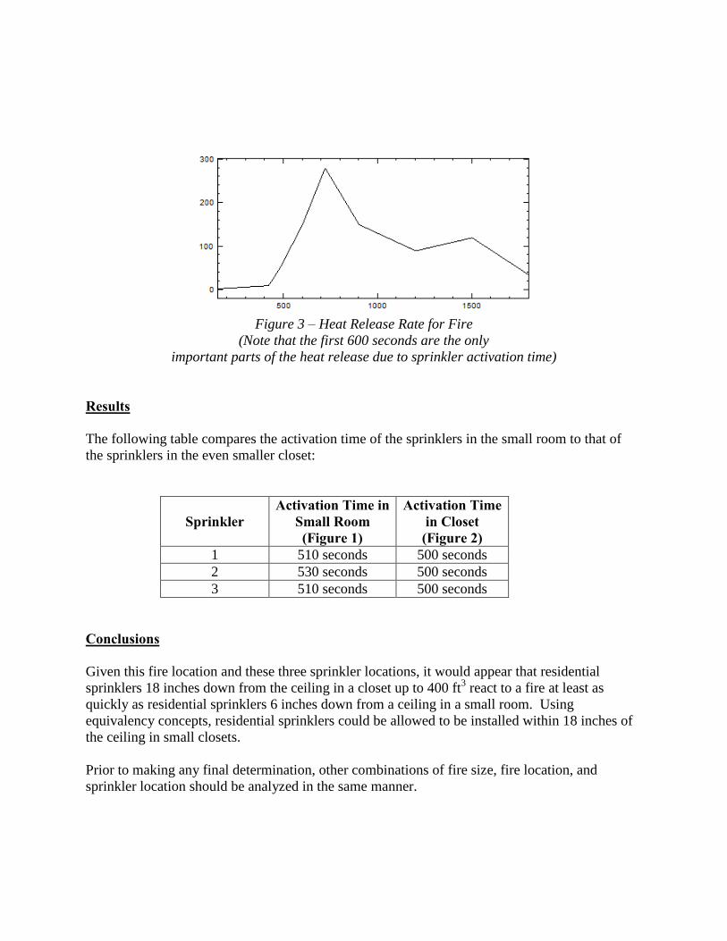
Figure 3 – Heat Release Rate for Fire
(Note that the first 600 seconds are the only
important parts of the heat release due to sprinkler activation time)
Results
The following table compares the activation time of the sprinklers in the small room to that of
the sprinklers in the even smaller closet:
Sprinkler Activation Time in
Small Room (Figure 1)
Activation Time in Closet (Figure 2)
1 510 seconds 500 seconds
2 530 seconds 500 seconds
3 510 seconds 500 seconds
Conclusions
Given this fire location and these three sprinkler locations, it would appear that residential
sprinklers 18 inches down from the ceiling in a closet up to 400 ft3 react to a fire at least as
quickly as residential sprinklers 6 inches down from a ceiling in a small room. Using
equivalency concepts, residential sprinklers could be allowed to be installed within 18 inches of
the ceiling in small closets.
Prior to making any final determination, other combinations of fire size, fire location, and
sprinkler location should be analyzed in the same manner.

Public Comment No. 16-NFPA 13R-2014 [ New Section after 6.5 ]
New 6.5.4
Sprinkler-Protected Glazing.
Where sprinklers are used in combination with glazing as an alternative to a required fire-rated wall orwindow assembly, the sprinkler-protected assembly shall comply with the following:
(1) Sprinklers shall be listed as specific application window sprinklers.
(2) Sprinklers shall be supplied by a wet-pipe system.
(3) Glazing shall be heat-strengthened or tempered and shall be fixed.
(4) Where the assembly is required to be protected from both sides, sprinklers shall be installed on bothsides of the glazing.
(5) The use of sprinkler-protected glazing shall be limited to non-load-bearing walls.
(6) The glazed wall assembly shall not have any horizontal members that would interfere with uniformdistribution of water over the surface of the glazing, and there shall be no obstructions between sprinklersand glazing that would obstruct water distribution.
Annex
It is not the intent of this section to apply to sprinkler protection of glass atrium enclosures, pedestrianwalkways, which are permitted by NFPA 101, or model building codes to be protected by standard spraysprinklers installed in accordance with the special provisions set forth in those codes for atriumconstruction.
Statement of Problem and Substantiation for Public Comment
The proposed text was accepted as a First Revision but later removed by the TCC. The language previously approved by the 13R has also been submitted to the 13 committee as a comment.
Related Item
Public Input No. 74-NFPA 13R-2013 [New Section after 6.5.3]
Submitter Information Verification
Submitter Full Name: Mark Fessenden
Organization: Tyco Fire Protection Products
Street Address:
City:
State:
Zip:
Submittal Date: Thu May 08 15:23:41 EDT 2014
National Fire Protection Association Report http://submittals.nfpa.org/TerraViewWeb/ContentFetcher?commentPara...
13 of 31 5/21/2014 9:36 AM

Public Comment No. 25-NFPA 13R-2014 [ Section No. 6.6.7 ]
6.6.7
Sprinklers shall not be required in closets (regardless of size) on exterior balconies and exteriorbreezeways/corridors,and garages regardless of size, as long as the closet does not have doors orunprotected penetrations directly into the dwelling unit.
Statement of Problem and Substantiation for Public Comment
There would be limited difference of items being stored in closets on balconies or garages.
Related Item
Public Input No. 56-NFPA 13R-2013 [Section No. 6.4.6.3.2]
Submitter Information Verification
Submitter Full Name: Phillip Brown
Organization: American Fire Sprinkler Associ
Street Address:
City:
State:
Zip:
Submittal Date: Thu May 15 11:40:55 EDT 2014
National Fire Protection Association Report http://submittals.nfpa.org/TerraViewWeb/ContentFetcher?commentPara...
14 of 31 5/21/2014 9:36 AM

Public Comment No. 11-NFPA 13R-2014 [ Section No. 6.9.2 ]
6.9.2
The drain pipe shall be at least 1 in. (25 mm) nominal diameter and shall be arranged so that it can drainall portions of the system .
Statement of Problem and Substantiation for Public Comment
This statement would indicate that you could never have a trapped section of water.
Related Item
Public Input No. 28-NFPA 13R-2012 [Section No. 6.9.2]
Submitter Information Verification
Submitter Full Name: Peter Schwab
Organization: Wayne Automatic Fire Sprinkler
Street Address:
City:
State:
Zip:
Submittal Date: Thu Apr 17 11:50:31 EDT 2014
National Fire Protection Association Report http://submittals.nfpa.org/TerraViewWeb/ContentFetcher?commentPara...
15 of 31 5/21/2014 9:36 AM

Public Comment No. 12-NFPA 13R-2014 [ New Section after 6.11.5 ]
6.11.6 Fire department connections shall have an approved method to deter unauthorized removalof the FDC.
Statement of Problem and Substantiation for Public Comment
NFPA 13R is a design and installation standard and as such does address the security, protection, and assurance that the various components of required sprinkler systems will function properly when needed. This is seen in various sections including: • Sprinklers subject to mechanical injury shall be protected...,• Requiring approved plugs and caps to protect fire department connections from blockage and debris, In order to assure that fire department connections are present and operate properly in the event of fire they must be protected from theft or any unauthorized removal. Since the FDC is located outside of the protected structure they are more susceptible to theft than any other component. Theft of FDC’s has and is occurring nationwide and many times goes undetected until a fire when the fire department discovers they cannot pump into the system. This new section would allow the AHJ to approve different methods of deterring unauthorized removal of the FDC ranging from the use of locking methods to warning signage.
Related Item
Public Input No. 55-NFPA 13R-2013 [New Section after 6.11.4]
Submitter Information Verification
Submitter Full Name: Bill Galloway
Organization: Southern Regional Fire Code De
Street Address:
City:
State:
Zip:
Submittal Date: Thu Apr 17 12:53:11 EDT 2014
National Fire Protection Association Report http://submittals.nfpa.org/TerraViewWeb/ContentFetcher?commentPara...
16 of 31 5/21/2014 9:36 AM

Public Comment No. 17-NFPA 13R-2014 [ Section No. 6.11.5 ]
6.11.5 *
Fire department connections shall be permitted to connect to the underground piping dedicated to thesprinkler system where the pipe is rated for a pressure of at least 175 psi . Where the underground pipe isnonmetallic, the pressure rating shall be based on a temperature of at least 100 degrees Fahrenheit.
Statement of Problem and Substantiation for Public Comment
As NFPA 13R allows the underground piping to be any material acceptable under the plumbing code, when adding a FDC connection to this underground, the piping material must rated for 175 psi.
Related Item
First Revision No. 21-NFPA 13R-2013 [New Section after 6.11]
Submitter Information Verification
Submitter Full Name: Roland Asp
Organization: National Fire Sprinkler Association
Affilliation: NFSA E&S Committee
Street Address:
City:
State:
Zip:
Submittal Date: Mon May 12 11:43:34 EDT 2014
National Fire Protection Association Report http://submittals.nfpa.org/TerraViewWeb/ContentFetcher?commentPara...
17 of 31 5/21/2014 9:36 AM

Public Comment No. 13-NFPA 13R-2014 [ Section No. A.1.1 ]
National Fire Protection Association Report http://submittals.nfpa.org/TerraViewWeb/ContentFetcher?commentPara...
18 of 31 5/21/2014 9:36 AM

A.1.1
National Fire Protection Association Report http://submittals.nfpa.org/TerraViewWeb/ContentFetcher?commentPara...
19 of 31 5/21/2014 9:36 AM

Revisions to paragraph A.1.1 and A.7.2 are proposed as follows:
1. Replace the first 4 paragraphs of the 2013 edition of NFPA 13R Annex Note A.1.1
with new text as indicated below.
A.1.1 NFPA 13R is appropriate for use as an
alternativeoption to NFPA 13 only in those
residential occupancies, as defined in this standard, up to and including four
aboveground stories in height, and limited to buildings that are 60 ft (18 m) or less in
height above grade plane, which is consistent with limits established by model
building codes for buildings of Type V construction. The height of a building above
grade plane is determined by model building codes, which base the height on
the average height of the highest roof surface above grade plane. For further
information on the building height story limits, see model building codes.
Buildings that contain multiple occupancies (either separated or non-separated), accessory occupancies orincidental uses are often subject to special rules that may restrict the use of NFPA 13R. Refer to theadopted building code to determine whether such restrictions are applicable.
A building's height is determined in accordance with the applicable building code,
which will have its own methods for determining building and story heights. Under
the IBC and NFPA 101/5000 Codes, an NFPA 13R sprinkler system is permitted in a
residential occupancy where the building is limited to four stories above grade plane
(See 2012 NFPA 101 Section 30.3.5.2, 2012 NFPA 5000 Section 25.3.5.3 and 2012
IBC Section 903.3.1.2). Also, IBC and NFPA 5000 limit the height of this residential
occupancy to no more than 60 ft (18m) in height above grade plane (See 2012
NFPA 5000 Section 7.5.2 and 2012 IBC Section 504.2). Such buildings sprinklered
in accordance with NFPA 13R are permitted to have basement(s) below the grade
plane. The model building codes do not consider stories below the grade plane in
the determination of a buildings height.
It is the intent of this standard that if NFPA13R is appropriate for use, it be applied as
described in the following paragraphs.
There are model building code provisions, where portions of a structure are above
and below a three hour fire rated horizontal assembly, that consider the buildings
above and below the three hour fire rated horizontal assembly as separate and
distinct buildings (See 2012 NFPA 5000, Section 7.4.3.6.5 and 2012 IBC Section
510.2). In such types of structures (commonly called “pedestal/podium” design),
where the residential occupancy above the three hour fire rated horizontal assembly
is considered as a separated building(s) by the applicable building code, NFPA 13R
is permitted when the residential building(s) are a maximum of 4 stories above the
fire-rated horizontal separation, and such buildings are limited to 60 ft (18 m) or less
in height above the grade plane. See Figure A.1.1 for an example of a
pedestal/podium type structure.
Figure A.1.1 Example of a “pedestal/podium” type structure (Exhibit 7.4 from
Supplement 4 of 2013 Residential Sprinkler System Handbook)
It is recognized that accessory or incidental occupancies, as defined by the
applicable building code, related to the operations of the residential occupancy will
exist within that residential occupancy. Such accessory or incidental occupancies
National Fire Protection Association Report http://submittals.nfpa.org/TerraViewWeb/ContentFetcher?commentPara...
20 of 31 5/21/2014 9:36 AM

would be considered ancillary to the predominant or main occupancy (residential) of
the building and subject to the provisions of the predominant or main occupancy.
For instance see Section 6.1.14.1.3 of the 2012 NFPA 101 and similar provisions in
many local building/model building codes (See 2012 NFPA 5000 Sections 6.2.1.3,
6.2.1.4 & 6.2.1.5, and 2012 IBC Sections 508.2 & Section 509). Use of NFPA13R
throughout the entire building including related accessory or incidental occupancies
such as parking garages/areas, community laundry rooms, clubhouses, exercise
facilities, tenant storage spaces, maintenance rooms, storage rooms, leasing offices,
lobbies, community gathering spaces, small conference rooms, small gift shops, and
so forth would be permitted. Note that for these incidental or accessory
occupancies, it is the intent of NFPA 13R to reference the sprinkler discharge (flow
and pressure), number of design sprinklers, and position of sprinkler (distance from
walls, ceilings, and other sprinklers) requirements of NFPA 13. It is not the intent to
apply other rules from NFPA 13, such as sprinkler coverage of combustible
concealed spaces, hose stream demand, and water supply duration. See section
7.2 and associated annex.
For a building containing multiple occupancies utilizing the “separated” occupancy
provisions in accordance with the applicable building code, residential occupancies
are within the scope of NFPA 13R provided the building is not more than 4 stories in
height, does not exceeding 60' in height above grade plane, and the residential
occupancy is separated from the other occupancies in accordance with the
“separated” occupancy requirements of the applicable building code (For example
see 2012 NFPA 5000 Sections 6.2.2.3 & 6.2.4, and 2012 IBC Section 508.4). In
such cases, NFPA 13R can be used in the residential occupancies and NFPA 13 is
to be used in the other non-residential occupancies in the building.
A building containing multiple occupancies utilizing the “non-separated” occupancy
provisions of the applicable building code is not within the scope of NFPA 13R. For
such a building, the applicable building code typically requires the use of an NFPA
13 system throughout the building. Residential buildings containing accessory or
incidental occupancies as described above are not considered multiple occupancy
buildings.
Residential occupancies in a building greater than four stories in height, or in a
building exceeding 60 ft (18m) in height above the grade plane, are not within the
scope of NFPA 13R.
A decision to use NFPA 13R in a building containing multiple (mixed) occupancies,
as defined in the model building codes and NFPA 101, can inherently impose
restrictions on the building, which should be made known at the time of design and
construction. Architects, engineers, and code officials are cautioned that the locally
adopted statutes, ordinances and codes that require sprinklers for certain
occupancies or buildings may also provide certain compensatory building features
(commonly called “trade-offs”) for the installation of the fire sprinkler system. If such
“sprinkler trade-offs” are given in these adopted statutes, ordinances and codes for
only buildings sprinklered throughout in accordance with NFPA 13, then to permit
such occupancies or buildings to apply such “trade-offs”, the occupancies or
National Fire Protection Association Report http://submittals.nfpa.org/TerraViewWeb/ContentFetcher?commentPara...
21 of 31 5/21/2014 9:36 AM

buildings would be required to be sprinklered in accordance with NFPA 13, not
NFPA 13R. (For example see 2012 NFPA 5000 Sections 7.6.2.2, 7.4.3.6.5(4b), and
Footnote “†” to Tables 6.2.4.1(a) & (b); and 2012 IBC Sections 504.2, 510.2(6), and
Footnotes “S” and “NS” to Table 508.4).
Decisions to use passive (fire resistive) construction to provide separation between
the residential occupancy having an NFPA 13R sprinkler system and adjacent
occupancies will likely not be permitted to have reductions in the required hourly
rating which would be permitted to be applied for buildings having an NFPA 13
sprinkler system installed throughout all portions of the building, including residential.
In addition, area and height increases above the base (tabular) values defined by the
model building codes for the various occupancies would not be applicable for
buildings having an NFPA 13R sprinkler system in the residential occupancy portion
(s) of the building. These height and area increases are typically limited to buildings
having NFPA 13 sprinkler systems installed throughout in accordance with the model
building code.
In summary, the determination of the applicable sprinkler standard(s) required for the
occupancies in a building will be ultimately determined through the locally adopted
statutes, ordinances and codes.
2. Revise Annex Note A.7.2 as follows:
A.7.2 It is only the intent of NFPA 13R to reference the sprinkler discharge (flow and
pressure), number of design sprinklers, and position of sprinklers (distance from
walls, ceilings, and other sprinklers) requirements of NFPA 13. Other rules from
NFPA 13 such as sprinklering of combustible concealed spaces, hose stream
demand, and water supply duration are not intended to be referenced by Section
7.2. It is also the intent of Section 7.2 to apply to those systems or portions of
systems that are outside the dwelling unit but have been determined to be
considered residential, accessory, or incidental to residential, and within the scope of
this standard. (Also see A.1.1.)
The criteria in this standard are based on full-scale fire tests of rooms containing typical furnishings found inresidential living rooms, kitchens, and bedrooms. The furnishings were arranged as typically found indwelling units in a manner similar to that shown in Figure A.1.1(a) , Figure A.1.1(b) , and Figure A.1.1(c).Sixty full-scale fire tests were conducted in a two-story dwelling in Los Angeles, California, and 16 testswere conducted in a 14 ft (4.3 m) wide mobile home in Charlotte, North Carolina. Sprinkler systemsdesigned and installed according to this standard are expected to prevent flashover within the compartmentof origin where sprinklers are installed in the compartment. A sprinkler system designed and installedaccording to this standard cannot, however, be expected to completely control a fire involving fuel loads
that are significantly higher than average for dwelling units [10 lb/ft2 (49 kg/m2)], configurations of fuelsother than those with typical residential occupancies, or conditions where the interior finish has anunusually high flame spread index (greater than 225).
To be effective, sprinkler systems installed in accordance with this standard need to open the sprinklersclosest to the fire before the fire exceeds the ability of the sprinkler discharge to extinguish or control thefire. Conditions that allow the fire to grow beyond that point before sprinkler activation or that interfere withthe quality of water distribution can produce conditions beyond the capabilities of the sprinkler systemdescribed in this standard. Unusually high ceilings or ceiling configurations that tend to divert the rising hotgases from sprinkler locations or change the sprinkler discharge pattern from its standard pattern canproduce fire conditions that cannot be extinguished or controlled by the systems described in this standard.
NFPA 13R references NFPA 13 in many aspects (hanging and bracing, design densities and spacingoutside of dwelling unit, painting and finish of sprinklers, welding, etc.). If this standard does not specificallyaddress a situation, NFPA 13 is a good resource that can be utilized by the installer and the authority
National Fire Protection Association Report http://submittals.nfpa.org/TerraViewWeb/ContentFetcher?commentPara...
22 of 31 5/21/2014 9:36 AM

having jurisdiction for a solution. It is not the intent of this standard to require compliance with NFPA 13when NFPA 13R is silent on a subject. Only AHJ approval should be required.
Figure A.1.1(a) Bedroom.
Figure A.1.1(b) Manufactured Home Bedroom.
Figure A.1.1(c) Living Room.
Statement of Problem and Substantiation for Public Comment
National Fire Protection Association Report http://submittals.nfpa.org/TerraViewWeb/ContentFetcher?commentPara...
23 of 31 5/21/2014 9:36 AM

Accept the Committee Input. Telling the user to simply go to the building code is a disservice. Many Fire Officials are not Building Code experts. This section gives great guidance on when 13R is applicable.
Related Item
Committee Input No. 33-NFPA 13R-2013 [Global Input]
Submitter Information Verification
Submitter Full Name: Peter Schwab
Organization: Wayne Automatic Fire Sprinkler
Street Address:
City:
State:
Zip:
Submittal Date: Tue Apr 29 11:00:21 EDT 2014
National Fire Protection Association Report http://submittals.nfpa.org/TerraViewWeb/ContentFetcher?commentPara...
24 of 31 5/21/2014 9:36 AM

Public Comment No. 23-NFPA 13R-2014 [ Section No. A.5.2.3.2 ]
A.5.2.3.2
When fabricating steel pipe for a
system using nonmetallic and steel pipe
combination (CPVC–steel) system , the cutting oil and lubricants
might
can cause performance degradation of the
nonmetallic
CPVC piping. Cutting oils and lubricants found to be compatible are available and should be used.
Statement of Problem and Substantiation for Public Comment
This section has been has been revised to mirror the proposed wording of NFPA 13 annex section A.6.3.7.4. This "compatibility" section was intended to be consistent with the language proposed to NFPA 13.
Related Public Comments for This Document
Related Comment Relationship
Public Comment No. 20-NFPA 13R-2014 [Section No. 5.2.3.2] same concept
Public Comment No. 21-NFPA 13R-2014 [New Section after 5.2.12.2.1.4] same concept
Public Comment No. 22-NFPA 13R-2014 [New Section after A.5.2.12.2] smae concept
Related Item
First Revision No. 34-NFPA 13R-2013 [Sections 5.2.1, 5.2.2, 5.2.3, 5.2.4, 5.2.5, 5.2.6, 5.2.7, 5...]
Submitter Information Verification
Submitter Full Name: Roland Asp
Organization: National Fire Sprinkler Association
Affilliation: NFSA E&S Committee
Street Address:
City:
State:
Zip:
Submittal Date: Wed May 14 11:14:15 EDT 2014
National Fire Protection Association Report http://submittals.nfpa.org/TerraViewWeb/ContentFetcher?commentPara...
25 of 31 5/21/2014 9:36 AM

Public Comment No. 22-NFPA 13R-2014 [ New Section after A.5.2.12.2 ]
TITLE OF NEW CONTENT
Rubber-gasketed pipe fittings and couplings should not be installed where ambienttemperatures can be expected to exceed 150°F (66°C) unless listed for this service. Ifthe manufacturer further limits a given gasket compound, those recommendationsshould be followed.
Other construction materials include but are not limited to materials used in fabricationof the sprinkler system, additives to water supplies, cable and wiring, and certaininsecticides and fungicides.
Statement of Problem and Substantiation for Public Comment
This section has been has been added to correlate with the NFPA 13 section A.6.4.4. This "compatibility" section was intended to be consistent with the language proposed to NFPA 13. NFPA 13 section 6.4.4 should also be added to NFPA 13R - See Public comment 21.
Related Public Comments for This Document
Related Comment Relationship
Public Comment No. 21-NFPA 13R-2014 [New Section after 5.2.12.2.1.4]
Related Item
First Revision No. 34-NFPA 13R-2013 [Sections 5.2.1, 5.2.2, 5.2.3, 5.2.4, 5.2.5, 5.2.6, 5.2.7, 5...]
Submitter Information Verification
Submitter Full Name: Roland Asp
Organization: National Fire Sprinkler Association
Affilliation: NFSA E&S Committee
Street Address:
City:
State:
Zip:
Submittal Date: Wed May 14 11:06:41 EDT 2014
National Fire Protection Association Report http://submittals.nfpa.org/TerraViewWeb/ContentFetcher?commentPara...
26 of 31 5/21/2014 9:36 AM

Public Comment No. 24-NFPA 13R-2014 [ New Section after A.5.2.12.2 ]
A.2.12.2.1.2
When fabricating steel pipe for a system using non-metallic and steel pipe, the cutting oil and lubricantscan cause performance degradation of the non-metallic fitting.
Statement of Problem and Substantiation for Public Comment
This section has been has been revised to mirror the proposed wording of NFPA 13 annex section A.6.4.3.2. This "compatibility" section was intended to be consistent with the language proposed to NFPA 13.
Related Public Comments for This Document
Related Comment Relationship
Public Comment No. 20-NFPA 13R-2014 [Section No. 5.2.3.2] smae consept
Public Comment No. 21-NFPA 13R-2014 [New Section after 5.2.12.2.1.4] same concept
Public Comment No. 22-NFPA 13R-2014 [New Section after A.5.2.12.2] same concept
Public Comment No. 23-NFPA 13R-2014 [Section No. A.5.2.3.2] same concept
Related Item
First Revision No. 34-NFPA 13R-2013 [Sections 5.2.1, 5.2.2, 5.2.3, 5.2.4, 5.2.5, 5.2.6, 5.2.7, 5...]
Submitter Information Verification
Submitter Full Name: Roland Asp
Organization: National Fire Sprinkler Association
Affilliation: NFSA E&S Committee
Street Address:
City:
State:
Zip:
Submittal Date: Wed May 14 11:29:04 EDT 2014
National Fire Protection Association Report http://submittals.nfpa.org/TerraViewWeb/ContentFetcher?commentPara...
27 of 31 5/21/2014 9:36 AM

Public Comment No. 8-NFPA 13R-2014 [ Section No. A.6.6.5 ]
National Fire Protection Association Report http://submittals.nfpa.org/TerraViewWeb/ContentFetcher?commentPara...
28 of 31 5/21/2014 9:36 AM

A.6.6.5
National Fire Protection Association Report http://submittals.nfpa.org/TerraViewWeb/ContentFetcher?commentPara...
29 of 31 5/21/2014 9:36 AM

An example of an open corridor or exterior corridor , stair, or breezeway is one that is exposed to theoutside atmosphere (temperature). Another example is an exterior wraparound corridor that is typical in atwo- to three-story motel. [See Figure A.6.6.5(a) through Figure A.6.6.5(e).]
Figure A.6.6.5(a) Example of Open Corridor or exterior Corridor — Arrangement 1.
Figure A.6.6.5(b) Example of Open Corridor or exterior Corridor — Arrangement 2.
Figure A.6.6.5(c) Example of Open Corridor or exterior Corridor — Arrangement 3.
Figure A.6.6.5(d) Example of Open Corridor or exterior Corridor — Arrangement 4.
Figure A.6.6.5(e) Example of Open or exterior Corridor — Arrangement 5.
National Fire Protection Association Report http://submittals.nfpa.org/TerraViewWeb/ContentFetcher?commentPara...
30 of 31 5/21/2014 9:36 AM

Statement of Problem and Substantiation for Public Comment
The charging language in the body of the standard refers to exterior breezeways/corridors. The annex language should indicate the same terminology.
Related Item
Public Input No. 27-NFPA 13R-2012 [Section No. 6.6.7]
Submitter Information Verification
Submitter Full Name: Peter Schwab
Organization: Wayne Automatic Fire Sprinkler
Street Address:
City:
State:
Zip:
Submittal Date: Mon Mar 17 13:31:04 EDT 2014
National Fire Protection Association Report http://submittals.nfpa.org/TerraViewWeb/ContentFetcher?commentPara...
31 of 31 5/21/2014 9:36 AM