technical data - link-belt cranes · 1 5790 (supersedes 5778)-0118-t6 link‐belt cranes 110rt...
TRANSCRIPT

15790 (supersedes 5778)-0118-T6
110RTLink‐Belt Cranes
Telescopic Boom Rough Terrain Crane110 US ton
100 metric ton
Technical DataSpecifications & Capacities
CAUTION: This material is supplied for
reference use only. Operator must refer to
in-cab Crane Rating Manual and Operator's
Manual to determine allowable crane lifting
capacities and assembly and operating
procedures.

5790 (supersedes 5778)-0118-T6
110RT Link‐Belt Cranes

5790 (supersedes 5778)-0118-T6
110RTLink‐Belt Cranes
Table Of ContentsBoom, Attachments, and Upper Structure 1. . . . . . . . . . . . . . . . . . . . . . . . . . . . . . . . . . . . . . . . . . . . . . . . . . . .
Boom 1. . . . . . . . . . . . . . . . . . . . . . . . . . . . . . . . . . . . . . . . . . . . . . . . . . . . . . . . . . . . . . . . . . . . . . . . . . . . . . . . . . . .
Boom 1. . . . . . . . . . . . . . . . . . . . . . . . . . . . . . . . . . . . . . . . . . . . . . . . . . . . . . . . . . . . . . . . . . . . . . . . . . . . . . . . . . .
Boom Wear Pads 1. . . . . . . . . . . . . . . . . . . . . . . . . . . . . . . . . . . . . . . . . . . . . . . . . . . . . . . . . . . . . . . . . . . . . . . . .
Boom Head 1. . . . . . . . . . . . . . . . . . . . . . . . . . . . . . . . . . . . . . . . . . . . . . . . . . . . . . . . . . . . . . . . . . . . . . . . . . . . .
Boom Elevation 1. . . . . . . . . . . . . . . . . . . . . . . . . . . . . . . . . . . . . . . . . . . . . . . . . . . . . . . . . . . . . . . . . . . . . . . . . .
Auxiliary Lifting Sheave - Optional 1. . . . . . . . . . . . . . . . . . . . . . . . . . . . . . . . . . . . . . . . . . . . . . . . . . . . . . . . .
Hook Blocks and Balls - Optional 1. . . . . . . . . . . . . . . . . . . . . . . . . . . . . . . . . . . . . . . . . . . . . . . . . . . . . . . . . .
Fly - Optional 1. . . . . . . . . . . . . . . . . . . . . . . . . . . . . . . . . . . . . . . . . . . . . . . . . . . . . . . . . . . . . . . . . . . . . . . . . . .
Fly Extensions - Optional 1. . . . . . . . . . . . . . . . . . . . . . . . . . . . . . . . . . . . . . . . . . . . . . . . . . . . . . . . . . . . . . . . .
Operator's Cab and Controls 2. . . . . . . . . . . . . . . . . . . . . . . . . . . . . . . . . . . . . . . . . . . . . . . . . . . . . . . . . . . . . . . .
Swing 3. . . . . . . . . . . . . . . . . . . . . . . . . . . . . . . . . . . . . . . . . . . . . . . . . . . . . . . . . . . . . . . . . . . . . . . . . . . . . . . . . . . .
Electrical 3. . . . . . . . . . . . . . . . . . . . . . . . . . . . . . . . . . . . . . . . . . . . . . . . . . . . . . . . . . . . . . . . . . . . . . . . . . . . . . . . .
Load Hoist System 4. . . . . . . . . . . . . . . . . . . . . . . . . . . . . . . . . . . . . . . . . . . . . . . . . . . . . . . . . . . . . . . . . . . . . . . . .
Load Hoist Performance 4. . . . . . . . . . . . . . . . . . . . . . . . . . . . . . . . . . . . . . . . . . . . . . . . . . . . . . . . . . . . . . . . . . .
2M Main and Optional Auxiliary Winches 4. . . . . . . . . . . . . . . . . . . . . . . . . . . . . . . . . . . . . . . . . . . . . . . . . . . .
Hydraulic System 4. . . . . . . . . . . . . . . . . . . . . . . . . . . . . . . . . . . . . . . . . . . . . . . . . . . . . . . . . . . . . . . . . . . . . . . . . .
Counterweight 4. . . . . . . . . . . . . . . . . . . . . . . . . . . . . . . . . . . . . . . . . . . . . . . . . . . . . . . . . . . . . . . . . . . . . . . . . . . .
Carrier 5. . . . . . . . . . . . . . . . . . . . . . . . . . . . . . . . . . . . . . . . . . . . . . . . . . . . . . . . . . . . . . . . . . . . . . . . . . . . . . . . . . . .
General 5. . . . . . . . . . . . . . . . . . . . . . . . . . . . . . . . . . . . . . . . . . . . . . . . . . . . . . . . . . . . . . . . . . . . . . . . . . . . . . . . . . .
Outriggers 5. . . . . . . . . . . . . . . . . . . . . . . . . . . . . . . . . . . . . . . . . . . . . . . . . . . . . . . . . . . . . . . . . . . . . . . . . . . . . . . .
Steering and Axles 5. . . . . . . . . . . . . . . . . . . . . . . . . . . . . . . . . . . . . . . . . . . . . . . . . . . . . . . . . . . . . . . . . . . . . . . . .
Suspension 5. . . . . . . . . . . . . . . . . . . . . . . . . . . . . . . . . . . . . . . . . . . . . . . . . . . . . . . . . . . . . . . . . . . . . . . . . . . . . . .
Tires and Wheels 5. . . . . . . . . . . . . . . . . . . . . . . . . . . . . . . . . . . . . . . . . . . . . . . . . . . . . . . . . . . . . . . . . . . . . . . . . .
Brakes 5. . . . . . . . . . . . . . . . . . . . . . . . . . . . . . . . . . . . . . . . . . . . . . . . . . . . . . . . . . . . . . . . . . . . . . . . . . . . . . . . . . .
Electrical 5. . . . . . . . . . . . . . . . . . . . . . . . . . . . . . . . . . . . . . . . . . . . . . . . . . . . . . . . . . . . . . . . . . . . . . . . . . . . . . . . .
Engine 5. . . . . . . . . . . . . . . . . . . . . . . . . . . . . . . . . . . . . . . . . . . . . . . . . . . . . . . . . . . . . . . . . . . . . . . . . . . . . . . . . . .
Transmission 5. . . . . . . . . . . . . . . . . . . . . . . . . . . . . . . . . . . . . . . . . . . . . . . . . . . . . . . . . . . . . . . . . . . . . . . . . . . . . .
Fuel Tank 6. . . . . . . . . . . . . . . . . . . . . . . . . . . . . . . . . . . . . . . . . . . . . . . . . . . . . . . . . . . . . . . . . . . . . . . . . . . . . . . . .
Hydraulic System 6. . . . . . . . . . . . . . . . . . . . . . . . . . . . . . . . . . . . . . . . . . . . . . . . . . . . . . . . . . . . . . . . . . . . . . . . . .
Pump Drive 6. . . . . . . . . . . . . . . . . . . . . . . . . . . . . . . . . . . . . . . . . . . . . . . . . . . . . . . . . . . . . . . . . . . . . . . . . . . . . . .
Maximum Speed 6. . . . . . . . . . . . . . . . . . . . . . . . . . . . . . . . . . . . . . . . . . . . . . . . . . . . . . . . . . . . . . . . . . . . . . . . . .
Gradeability 6. . . . . . . . . . . . . . . . . . . . . . . . . . . . . . . . . . . . . . . . . . . . . . . . . . . . . . . . . . . . . . . . . . . . . . . . . . . . . . .
Paint 6. . . . . . . . . . . . . . . . . . . . . . . . . . . . . . . . . . . . . . . . . . . . . . . . . . . . . . . . . . . . . . . . . . . . . . . . . . . . . . . . . . . . .
Additional Equipment Options 6. . . . . . . . . . . . . . . . . . . . . . . . . . . . . . . . . . . . . . . . . . . . . . . . . . . . . . . . . . . . . . .
Axle Loads 7. . . . . . . . . . . . . . . . . . . . . . . . . . . . . . . . . . . . . . . . . . . . . . . . . . . . . . . . . . . . . . . . . . . . . . . . . . . . . . . .
General Dimensions 8. . . . . . . . . . . . . . . . . . . . . . . . . . . . . . . . . . . . . . . . . . . . . . . . . . . . . . . . . . . . . . . . . . . . . . . .
Tier 4f / Stage IV 8. . . . . . . . . . . . . . . . . . . . . . . . . . . . . . . . . . . . . . . . . . . . . . . . . . . . . . . . . . . . . . . . . . . . . . . . . . .
Tier 3 / Stage IIIA 9. . . . . . . . . . . . . . . . . . . . . . . . . . . . . . . . . . . . . . . . . . . . . . . . . . . . . . . . . . . . . . . . . . . . . . . . . .
Working Range Diagram 10. . . . . . . . . . . . . . . . . . . . . . . . . . . . . . . . . . . . . . . . . . . . . . . . . . . . . . . . . . . . . . . . . . . .
164.1' Main Boom + 10' Fly 10. . . . . . . . . . . . . . . . . . . . . . . . . . . . . . . . . . . . . . . . . . . . . . . . . . . . . . . . . . . . . . . . .
Main Boom + Fly 11. . . . . . . . . . . . . . . . . . . . . . . . . . . . . . . . . . . . . . . . . . . . . . . . . . . . . . . . . . . . . . . . . . . . . . . . . .
Boom Extend Modes 12. . . . . . . . . . . . . . . . . . . . . . . . . . . . . . . . . . . . . . . . . . . . . . . . . . . . . . . . . . . . . . . . . . . . . . .
Main Boom Lift Capacity Charts - Imperial 13. . . . . . . . . . . . . . . . . . . . . . . . . . . . . . . . . . . . . . . . . . . . . . . . . .
19,200 lb Counterweight - Fully Extended Outriggers - 360° Rotation 13. . . . . . . . . . . . . . . . . . . . . . . . . . .
28,800 lb Counterweight - Fully Extended Outriggers - 360° Rotation 14. . . . . . . . . . . . . . . . . . . . . . . . . . .
Fly Attachment Lift Capacity Charts - Optional 15. . . . . . . . . . . . . . . . . . . . . . . . . . . . . . . . . . . . . . . . . . . . . . .
19,200 lb Counterweight - Fully Extended Outriggers - 360° Rotation 15. . . . . . . . . . . . . . . . . . . . . . . . . . .
Main Boom + 10 ft Manual Offset Fly (2°, 15°, 30° & 45° Offsets) 15. . . . . . . . . . . . . . . . . . . . . . . . . . . . .

5790 (supersedes 5778)-0118-T6
110RT Link‐Belt Cranes
28,800 lb Counterweight - Fully Extended Outriggers - 360° Rotation 16. . . . . . . . . . . . . . . . . . . . . . . . . . .
Main Boom + 10 ft Manual Offset Fly (2°, 15°, 30° & 45° Offsets) 16. . . . . . . . . . . . . . . . . . . . . . . . . . . . .
19,200 lb Counterweight - Fully Extended Outriggers - 360° Rotation 17. . . . . . . . . . . . . . . . . . . . . . . . . . .
164.1 ft Main Boom Length 17. . . . . . . . . . . . . . . . . . . . . . . . . . . . . . . . . . . . . . . . . . . . . . . . . . . . . . . . . . . . . . . .
28,800 lb Counterweight - Fully Extended Outriggers - 360° Rotation 18. . . . . . . . . . . . . . . . . . . . . . . . . . .
164.1 ft Main Boom Length 18. . . . . . . . . . . . . . . . . . . . . . . . . . . . . . . . . . . . . . . . . . . . . . . . . . . . . . . . . . . . . . . .
Main Boom Lift Capacity Charts - On Tires 19. . . . . . . . . . . . . . . . . . . . . . . . . . . . . . . . . . . . . . . . . . . . . . . . . .
19,200 lb Counterweight - On Tires - Stationary - Boom Centered Over Front Between Tire Tracks 19
19,200 lb Counterweight - On Tires - Pick & Carry (Creep) - Boom Centered Over Front 20. . . . . . . . .
19,200 lb Counterweight - On Tires - Stationary - 360° Rotation 20. . . . . . . . . . . . . . . . . . . . . . . . . . . . . .
Main Boom Lift Capacity Charts - 85% - Metric 21. . . . . . . . . . . . . . . . . . . . . . . . . . . . . . . . . . . . . . . . . . . . .
8.8t Counterweight - Fully Extended Outriggers - 360° Rotation 21. . . . . . . . . . . . . . . . . . . . . . . . . . . . . . .
13.2t Counterweight - Fully Extended Outriggers - 360° Rotation 22. . . . . . . . . . . . . . . . . . . . . . . . . . . . . .
Fly Attachment Lift Capacity Charts - 85% - Optional 23. . . . . . . . . . . . . . . . . . . . . . . . . . . . . . . . . . . . . . . .
13.2t Counterweight - Fully Extended Outriggers - 360° Rotation 23. . . . . . . . . . . . . . . . . . . . . . . . . . . . . .
Boom Length + 3.0m Manual Offset Fly (2°, 15°, 30° & 45° Offsets) 23. . . . . . . . . . . . . . . . . . . . . . . . . . .
50.0m Main Boom Length 24. . . . . . . . . . . . . . . . . . . . . . . . . . . . . . . . . . . . . . . . . . . . . . . . . . . . . . . . . . . . . . . . .
Main Boom Lift Capacity Charts - 85% - On Tires 25. . . . . . . . . . . . . . . . . . . . . . . . . . . . . . . . . . . . . . . . . . .
8.8t Counterweight - On Tires - Stationary - Boom Centered Over Front Between Tire Tracks 25. . . . .
8.8t Counterweight - On Tires - Pick & Carry (Creep) - Boom Centered Over Front 26. . . . . . . . . . . . . .
8.8t Counterweight - On Tires - Stationary - 360° Rotation 26. . . . . . . . . . . . . . . . . . . . . . . . . . . . . . . . . . .
Main Boom Lift Capacity Charts - 75%/ISO - Metric 27. . . . . . . . . . . . . . . . . . . . . . . . . . . . . . . . . . . . . . . . .
8.8t Counterweight - Fully Extended Outriggers - 360° Rotation 27. . . . . . . . . . . . . . . . . . . . . . . . . . . . . . .
13.2t Counterweight - Fully Extended Outriggers - 360° Rotation 28. . . . . . . . . . . . . . . . . . . . . . . . . . . . . .
Fly Attachment Lift Capacity Charts - 75%/ISO - Optional 29. . . . . . . . . . . . . . . . . . . . . . . . . . . . . . . . . . . .
13.2t Counterweight - Fully Extended Outriggers - 360° Rotation 29. . . . . . . . . . . . . . . . . . . . . . . . . . . . . .
Boom Length + 3.0m Manual Offset Fly (2°, 15°, 30° & 45° Offsets) 29. . . . . . . . . . . . . . . . . . . . . . . . . . .
50.0m Main Boom Length 30. . . . . . . . . . . . . . . . . . . . . . . . . . . . . . . . . . . . . . . . . . . . . . . . . . . . . . . . . . . . . . . . .
Main Boom Lift Capacity Charts - 75% - On Tires 31. . . . . . . . . . . . . . . . . . . . . . . . . . . . . . . . . . . . . . . . . . .
8.8t Counterweight - On Tires - Stationary - Boom Centered Over Front Between Tire Tracks 31. . . . .
8.8t Counterweight - On Tires - Pick & Carry (Creep) - Boom Centered Over Front 32. . . . . . . . . . . . . .
8.8t Counterweight - On Tires - Stationary - 360° Rotation 32. . . . . . . . . . . . . . . . . . . . . . . . . . . . . . . . . . .
15790 (supersedes 5778)-0118-T6
110RTLink‐Belt Cranes
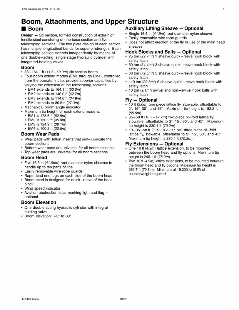
Boom, Attachments, and Upper Structure� BoomDesign - Six section, formed construction of extra hightensile steel consisting of one base section and fivetelescoping sections. The two plate design of each section
has multiple longitudinal bends for superior strength. Eachtelescoping section extends independently by means ofone double-acting, single stage hydraulic cylinder with
integrated holding valves.
Boom� 38-164.1 ft (11.6-50.0m) six section boom� Four boom extend modes (EM1 through EM4), controlled
from the operator's cab, provide superior capacities by
varying the extension of the telescoping sections:� EM1 extends to 164.1 ft (50.0m)� EM2 extends to 140.0 ft (42.7m)
� EM3 extends to 114.6 ft (34.9m)� EM4 extends to 89.5 ft (27.3m)
� Mechanical boom angle indicator� Maximum tip height for each extend mode is:� EM1 is 173.6 ft (52.9m)� EM2 is 150.2 ft (45.8m)� EM3 is 124.9 ft (38.1m)� EM4 is 100.2 ft (30.5m)
Boom Wear Pads� Wear pads with Teflon inserts that self-lubricate the
boom sections� Bottom wear pads are universal for all boom sections� Top wear pads are universal for all boom sections
Boom Head� Five 16.5 in (41.9cm) root diameter nylon sheaves to
handle up to ten parts of line� Easily removable wire rope guards� Rope dead end lugs on each side of the boom head� Boom head is designed for quick-reeve of the hook
block� Wind speed indicator� Aviation obstruction solar marking light and flag -
optional
Boom Elevation� One double acting hydraulic cylinder with integral
holding valve� Boom elevation: -3° to 80°
Auxiliary Lifting Sheave - Optional� Single 16.5 in (41.9m) root diameter nylon sheave� Easily removable wire rope guards� Does not affect erection of the fly or use of the main head
sheaves
Hook Blocks and Balls - Optional� 25 ton (22.7mt) 1 sheave quick-reeve hook block with
safety latch� 60 ton (54.4mt) 3 sheave quick-reeve hook block with
safety latch� 80 ton (72.5mt) 5 sheave quick-reeve hook block with
safety latch� 110 ton (99.8mt) 6 sheave quick-reeve hook block with
safety latch� 10 ton (9.1mt) swivel and non-swivel hook balls with
safety latch
Fly - Optional� 10 ft (3.0m) one piece lattice fly, stowable, offsettable to
2°, 15°, 30°, and 45°. Maximum tip height is 182.2 ft(55.5m).
� 35-58 ft (10.7-17.7m) two piece bi-fold lattice fly,stowable, offsettable to 2°, 15°, 30°, and 45°. Maximumtip height is 230.4 ft (70.2m).
� 10-35-58 ft (3.0-10.7-17.7m) three piece bi-foldlattice fly, stowable, offsettable to 2°, 15°, 30°, and 45°.Maximum tip height is 230.4 ft (70.2m).
Fly Extensions - Optional� One 16 ft (4.9m) lattice extension, to be mounted
between the boom head and fly options. Maximum tipheight is 246.1 ft (75.0m).
� Two 16 ft (4.9m) lattice extensions, to be mounted betweenthe boom head and fly options. Maximum tip height is261.7 ft (79.8m). Minimum of 19,200 lb (8.8t) ofcounterweight required.

2 5790 (supersedes 5778)-0118-T6
110RT Link‐Belt Cranes
� Operator's Cab and ControlsEnvironmental Cab - Fully enclosed, one person cab ofgalvaneal steel structure with acoustical insulationEquipped with:� Tinted and tempered glass windows� Extra-large fixed front window with windshield wiper and
washer� Swing up roof window with windshield wiper and washer� Sliding left side door with large fixed window� Sliding rear and right side windows for ventilation� Six way adjustable, cushioned seat with seat belt and
storage compartment� Diesel fired warm-water heater with air ducts for front
windshield defroster and cab floor� Defroster fan for the front window� Bubble level� Circulating fan� Adjustable sun screen� Dome lights� Cup holder� Fire extinguisher� Left side viewing mirror� Two position travel swing lock� AM/FM radio
Air Conditioning - Integral with cab heating systemutilizing the same ventilation outlets
Engine Dependant Warm-Water Heater - Optional -With air ducts for front windshield defroster and cab floor
Steering Column - Pedestal type with tilt and telescopefunctions for operator comfort. Column includes thefollowing controls and indicators:
Left and right levers include:� Horn button� Turn signal switch� Driving light switch� Transmission direction switch
Panel mounted switches for:� Travel park brake� Steer mode selector
� 2/4 wheel drive/range selector� Transmission gear selector� Hazard flasher
Panel mounted indicator/warning lights for:� Transmission temperature� Turn signals� Rear wheel offset� Emergency steer - optional
Armrest Controls - Two dual axis electronic joystickcontrollers or optional single axis electronic controllers for:� Cab heater and A/C Controls� Swing� Boom hoist� Main rear winch� Auxiliary front winch - optional� Drum rotation indication� Drum rotation indicator activation switch� Winch high/low speed and disable switch(es)� Warning horn button� Swing park brake� Engine throttle lock� Cab tilt
Outrigger Controls - Hand held control box with umbilicalcord gives the operator the freedom to view operation whilesetting the outriggers.
Foot Controls� Boom telescope� Swing brake� Engine throttle� Service brake
Right Front Console - Controls and indicators for:� Engine ignition � 12 volt power connections� Engine throttle lock � E-stop switch� Function lockout � Ignition switch on indicator� Front windshield wiper light
and washer � Boom floodlight's - optional� Cab floodlights � Rotating beacon/Strobe� Warning horn light - optional� Console dimmer switch � Outrigger floodlight switch� Bubble level � Gauge alarm� RCL alarm � Cab bar light

35790 (supersedes 5778)-0118-T6
110RTLink‐Belt Cranes
Cab Instrumentation - Ergonomically positioned USBdiagnostic center including digital instrumentation for craneoperation:� Tachometer � Swing park brake light� Engine water temperature � Engine speed� Fuel level � Engine oil pressure� Hydraulic oil temperature � Battery voltage� Stop engine � Fuel rate (gal/hr)� Check engine � Engine load� Wait to start � Engine Diagnostics� Diesel exhaust fluid (DEF) level(1)
� Engine air filter high restriction light(1)
� Regeneration light(1)
� Regeneration inhibit switch(1)
� Regeneration initiate switch(1)
� High exhaust temperature light(1)
� Regeneration disabled light(1)
(1) (Tier 4f / Stage IV engine only)
Camera Display - Located on dash console� Displays right side of upper� Displays main and auxiliary winches� Displays rear view
Diagnostic Center - Located on the left side of the front panel below the windshield� Engine diagnostic� RCL CANBUS diagnostic� Boom CANBUS diagnostic� Outrigger CANBUS diagnostic
LinkBelt Pulse – The LinkBelt inhouse designed, totalcrane operating system that utilizes the display as areadout and operator interface for the following systems:� Rated capacity limiter – LCD graphic audio – visual
warning system integrated into the dash with anti – twoblock and function limiter. Operating data includes:� RCL controller USB diagnostic
� Crane configuration� Boom length and angle� Boom head height
� Allowed load and % of allowed load� RCL light bar� Boom angle
� Radius of load� Actual load� Wind speed� Highlighted unit of measurement on working screen
� Active pin/latch status� Telescope operation displayed in real time� Outrigger position sensing
� Drum rotation direction indication� Third wrap indicator - optional� Diagnostics
� Operator settable alarms (include):• Maximum and minimum boom angles• Maximum tip height
• Maximum boom length• Swing left/right positions• Operator defined area (imaginary plane)
� Extend control module (ECM)� Controls the extend modes� Diagnostics
� Internal RCL Light Bar - Visually informs the operatorwhen crane is approaching maximum load capacity witha series of green, yellow, and red lights.
� Telematics – Cellular based data logging and monitoringsystem that provides:� Location and operational settings
� Routine maintenance� Crane and engine monitoring� Diagnostic and fault codes
Integrated Third Wrap Indicator - Optional - Link‐BeltPulse color display visually and audibly warns the operatorwhen the wire rope is on the first/bottom layer and when
the wire rope is down to the last three wraps.
Integrated Third Wrap Function Kickout - Optional -Link-Belt Pulse color display visually and audibly warnsthe operator when the wire rope is on the first/bottom layer
and provides a function kickout when the wire rope is downto the last three wraps.
External RCL Light Bar - Optional - Visually informs theground crew when crane is approaching maximum loadcapacity with a series of green, yellow, and red lights.
� SwingMotor/Planetary - Bi-directional hydraulic swing motormounted to a planetary reducer for 360° continuoussmooth swing at 1.9 rpm
Swing Park Brake - 360°, electric over hydraulic, (springapplied/hydraulic released) multi-disc brake mounted onthe speed reducer. Operated by a switch from theoperator's cab.
Swing Brake - 360°, foot operated, hydraulic applied discbrake mounted to the speed reducer.
Swing Lock - Two-position swing lock (boom over frontor rear) operated from the operator's cab.
360° Positive Swing Lock - Optional - Meets New YorkCity requirement
� ElectricalSwing Alarm - Audio warning device signals when theupper is swinging.
Lights� Two LED working lights on front of the cab� One amber strobe beacon on top of the cab� One rotating amber beacon on top of the cab - optional� One LED working light on top of cab - optional� LED Boom floodlight - Single - optional� LED Boom floodlight - Dual - optional� LED Boom floodlight - High intensity remote controlled
- optional� LED Frame worklights - right front, left rear, and work
platform - optional

4 5790 (supersedes 5778)-0118-T6
110RT Link‐Belt Cranes
� Load Hoist SystemLoad Hoist Performance
Main (Rear) and Auxiliary (Front) Winches - 3/4 in (19mm) Rope
Maximum Line Pull Normal Line Speed High Line Speed Layer Total
Layer lb kN ft/min m/min ft/min m/min ft m ft m
1 20,739 92.25 168 51.2 334 101.8 114 34.7 114 34.7
2 19,066 84.81 183 55.8 363 110.6 124 37.8 238 72.5
3 17,644 78.48 198 60.4 393 119.8 134 40.8 372 113.4
4 16,419 73.04 213 64.9 422 128.6 144 43.9 516 157.3
5 15,353 68.29 227 69.2 451 137.5 154 46.9 670 204.2
6 --- --- --- --- --- --- 164 50.0 834 254.2
Wire Rope ApplicationDiameter
Type
MaximumPermissible Load
in mm lb kg
Main (Rear) WinchStandard 3/4 19 37x7 rotation resistant - right lang lay (Type KC) 16,000 7 257.5
Optional 3/4 19 35x7 rotation resistant - right lang lay (Type CC) 17,160 7 783.6
Auxiliary (Front)Winch
Standard 3/4 19 37x7 rotation resistant - right lang lay (Type KC) 16,000 7 257.5
Optional 3/4 19 35x7 rotation resistant - right lang lay (Type CC) 17,160 7 783.6
2M Main and Optional Auxiliary Winches� Axial piston, full and half displacement (2-speed) motors
driven through planetary reduction unit for positivecontrol under all load conditions.
� Grooved lagging� Power up/down mode of operation� Hoist drum cable follower - optional� Drum rotation indicator� Drum diameter: 16 in (40.6cm)� Rope length:� Main: 730 ft (222.5m)� Auxiliary: 600 ft (182.88m) or 730 ft (222.5m)
� Maximum rope storage: 834 ft (254.2m)� Terminator style socket and wedge
� Hydraulic SystemCounterbalance Valves - All hoist motors, boom extendcylinders, and boom hoist cylinders are equipped withcounterbalance valves to provide load lowering andprevents accidental load drop when hydraulic power issuddenly reduced.
� CounterweightStandard - Total of 19,200 lb (8.8t) counterweightconsisting of two counterweights pinned to the upper withcapacities for:
� 0 lb (0t) counterweight*� 9,600 lb (4.4t) counterweight� 19,200 lb (8.8t) counterweight
Hydraulic counterweight removal activated by a hand-heldcontroller with enough cable to access the pins on eachside of the counterweights.
Optional - 9,600 lb (4.4t) in addition to standardcounterweight for a total of 28,800 lb (13.2t)counterweight with capacities for:
� 0 lb (0t) counterweight*� 9,600 lb (4.4t) counterweight� 19,200 lb (8.8t) counterweight� 28,800 lb (13.2t) counterweight*
* Travel speed limited to 5 mph.

55790 (supersedes 5778)-0118-T6
110RTLink‐Belt Cranes
Carrier
� General� 10 ft 11 in (3.33m) wide� 14 ft 4 in (4.37m) wheelbase (centerline of first axle to
centerline of second axle)
Frame - Box-type, torsion resistant, welded constructionmade of high tensile steel. Equipped with front and reartowing and tie-down lugs, tow connections, and accessladders.
� OutriggersBoxes - Two double box, front and rear welded to carrierframe
Beams and Jacks - Four single stage beams withConfined Area Lifting Capacities (CALC�) provideselectable outrigger extensions of full, intermediate, andretracted. Hydraulically controlled from the operator's cabwith integral check valves.
Pontoons - Four lightweight, serviceable, quick release,24 in diameter (60.96cm2), steel pontoons with contactarea of 452 in2 (2 918cm2) can be stored for road travel in storage rackson the carrier.
Main Jack Reaction - 112,600 lb (51 074kg) force and249 psi (1 716kPa) ground bearing pressure.
� Steering and AxlesSteering - Four independent modes consisting of twowheel front, two wheel rear, four wheel, and crab. Eachmode is controlled from the steering wheel and is selectedby a switch in the operator's cab.
Drive - Two modes: 4 x 2 and 4 x 4 for off highway travelAxle 1 - Steered, non-driven for 4 x 2 and steered, drivenfor 4 x 4Axle 2 - Steered, driven
� SuspensionFront - Rigid mount to the carrier frame
Rear - The rear axle is suspended on the oscillationcylinders with motion of the axle controlled by a four bargreaseless linkage system. The oscillation cylinderslockout when the upper structure rotates 2.5° pastcenterline.� Hydro-gas rear suspension - optional
Ride Height Adjustment - Suspension can be lowered fortransport using a hand-held controller from level ground.
� Tires and WheelsFront and Rear - Four (single) 29.5 x 25-34 ply rating,earthmover type tires on steel disc wheels� Spare tires and wheels - optional
� BrakesService - Full hydraulic, dual circuit, disc type brakes onall wheel ends
Parking/Emergency - Spring applied type, acting on frontaxle
� ElectricalTwo batteries provide 12 volt starting and operation
Lights (LED)� LED Front lighting includes two main headlights and two
parking/directional indicators.� LED Side lighting includes two parking/directional
indicators per side.� LED Rear lighting includes two parking/directional
indicators, two parking/brake lights, and two reversinglights.
� LED outrigger lights.� Other equipment includes hazard/warning system, cab
light, instrument panel light, and signal horn.
� Engine
Specification Cummins QSB
Emissions Compliance Level:
Tier 4f/Stage IV(1) Tier 3/Stage IIIA(2)
Numbers of Cylinders
6 6
Cycle 4 4
Bore and Stroke:inch (mm)
4.21 x 4.88 (107 x124)
4.21 x 4.88 (107 x124)
Piston Displacement:in3 (L)
408 (6.7) 408 (6.7)
Max. Brake Horsepower: hp (kW)
270 (201) @ 2,000rpm
270 (201) @ 2,000rpm
260 (194) @ 2,200rpm
260 (194) @ 2,200rpm
Peak Torque: ft lb(Nm)
730 (990) @ 1,500rpm
730 (990) @ 1,500rpm
Electric/starting systems: volts
12/12 12/12
Alternator: amps 190 190
Crankcase Capacity:qt (L)
15 (14.2) 15 (14.2)
� Water/fuel separator w/ heater and water in fuel (WIF) sensor
� 120-volt block heater - Tier 4f / Stage IV
� 220-volt block heater - Tier 3 / Stage IIIA
� Grid heater - 200 amp
� Mechanically driven, variable speed, engine controlled, viscous fanclutch
� (1) Can only be sold and/or operated where Tier 4f and Stage IVoff-highway emission standards are accepted.
� (2) Can only be sold and/or operated where Tier 3 and Stage IIIAoff-highway emission standards are accepted.
� TransmissionPowershift - Three speed with high/low range for 6forward and 6 reverse gears. Front axle disconnect for twoor four wheel drive. Front axle disconnects in high range.

6 5790 (supersedes 5778)-0118-T6
110RT Link‐Belt Cranes
� Fuel TankOne 75 gallon (283.9L) capacity tank
Diesel Exhaust Fluid (DEF) tank� One 5 gal (18.9L) capacity tank
� Hydraulic SystemAll functions are hydraulically powered allowing positiveprecise control with independent or simultaneous operationof all functions.
Main Pumps� One two section fixed displacement gear pump for the
front/rear winches and boom hoist/telescope circuits.� One two section fixed displacement gear pump for the
swing/steering and outrigger/telescope/servicebrake/oscillation circuits.
� One two section gear pump for an additional supply tothe front/rear winch circuit and the hydraulic oil cooler fandrive.
� Combined pump capacity of 138 gpm (522.4Lpm)
Hydraulic Reservoir - 153 gal (579.2L) capacity equippedwith sight level gauge. Diffusers built in for deaeration.
Filtration - One 10 micron, full flow return line filter.Accessible for easy filter replacement.
Hydraulic Oil Coolers - One carrier mounted coolerremoves heat from the hydraulic oil. Remote mounted onright side of the carrier.
� Pump DriveOne pump is mounted on the engine with the rest beingtransmission mounted. All pumps are mechanically drivenby the diesel engine.� Front/rear winches and boom hoist/telescope pump can
be disconnected with a manual pump disconnect to aidin cold weather starting.
� Maximum Speed18.5 mph (29.8 km/h)
� PaintEntire machine is prepainted and oven baked withHighsolid Paint (2 part epoxy/polyester) and/or (2 partepoxy primer/2 part polyurethane top coat). StandardLinkBelt Red, LinkBelt Gray, and Gloss Black colors apply.
� Additional Equipment Options� Spark arrestor� Engine air intake shutoff valve
� Gradeability
CounterweightAscending Descending Side
Degrees % Grade Degrees % Grade Degrees % Grade
0 17.0 31% 4.0 7%
3.0 5%9,600 (4.4t) 16.0 29% 15.0 27%
19,200 lbs (8.8t) 14.5 26% 14.5 26%
28,800 lbs (13.2t) 13.0 23% 13.0 23%

75790 (supersedes 5778)-0118-T6
110RTLink‐Belt Cranes
Axle Loads
Base crane with zerocounterweight and fulltank of fuel
Gross VehicleWeight (1)
Upper Facing Front Upper Facing Rear
Front Axles Rear Axles Front Axles Rear Axles
lb kg lb kg lb kg lb kg lb kg
Tier 4f / Stage IV 87,534 39 705 57,902 26 264 29,632 13 441 23,132 10 493 64,402 29 212
Tier 3 / Stage IIIA 86,902 39,418 57,708 26 176 29,194 13 242 22,938 10 405 63,964 29 014
Pintle hook, front 14 6 19 9 -5 -2 19 9 -5 -2
Pintle hook, rear 14 6 -6 -3 20 9 -6 -3 20 9
Hydro-gas suspension 56 25 21 10 35 16 21 10 35 5
Operator in cab 250 113 140 64 110 50 110 50 140 64
Hoist drum follower - main 69 31 -24 -11 93 42 93 42 -24 -11
Auxiliary winch with 600 ft (182.9m) wire rope 738 335 -90 -41 828 376 828 376 -90 -41
Hoist drum follower - auxiliary 69 31 -6 3 75 34 75 34 -6 3
Substitute 600 ft (182.9m) wire rope with 730ft (222.5m) - auxiliary
158 72 -5 -2 163 74 163 74 -5 -2
Remove 730 ft (222.5m) wire rope from rear(main) winch
-902 -409 197 89 -1,098 -498 -1,098 -498 197 89
Remove 600 ft (182.9m) wire rope from front(auxiliary) winch
-744 -337 24 11 -768 -348 -768 -348 24 11
One slab of counterweight on upper 9,600 4 355 -3,356 -1 522 12,956 5 877 12,956 5 877 -3,356 -1 522
Two slabs of counterweight on upper 19,200 8 709 -6,712 -3 045 25,912 11 754 25,912 11 754 -6,712 -3 045
Three slabs of counterweight on upper 28,800 13 064 -10,068 -4 567 38,868 17 630 38,868 17 630 -10,068 -4 567
Emergency steering 251 114 49 22 202 92 202 92 49 22
360° mechanical swing lock 140 64 72 33 68 31 68 31 72 33
Floodlight to front of boom base section 26 12 36 16 -10 -5 -10 -5 36 16
Fly mounting brackets to boom base sectionfor fly options
232 105 282 128 -50 -23 -50 -23 282 128
35 ft (10.67m) offsettable fly - stowed 1,595 723 2,618 1 188 -1,023 -464 -1,023 -464 2,618 1 188
35-58 ft (10.67-17.68m) offsettable fly -stowed
2,296 1 041 3,323 1 507 -1,027 -466 -1,027 -466 3,323 1 507
10 ft offsettable fly 1,062 482 2,541 1 153 -1,479 671 -1,479 671 2,541 1 153
10-35 ft offsettable fly 2,044 927 3,577 1 623 -1,533 -695 -1,533 -695 3,577 1 623
10-35-58 ft (3.0-10.67-17.68m) offsettablefly
2,745 1 245 4,283 1 943 -1,538 -698 -1,538 -698 4,283 1 943
Auxiliary lifting sheave 110 50 307 139 -197 -89 -197 -89 307 139
110 ton (81.6mt) 6-sheave hook block atbumper
1,985 900 3,012 1 366 -1,027 -466 -1,027 -466 3,012 1 366
80 ton (72.5mt) 5-sheave hook block atbumper
1,406 638 2,134 968 -728 -330 -728 -330 2,134 968
60 ton (54.4mt) 3-sheave hook block atbumper w/o weights
805 365 1,222 554 -417 -189 -417 -189 1,222 554
60 ton (54.4mt) 3-sheave hook block atbumper w/ 3 sets of weights
1,345 610 2,041 926 -696 -316 -696 -316 2041 926
25 ton (54.4mt) 1-sheave hook block atbumper
750 340 1,138 516 -388 -176 -388 -176 1,138 516
10 ton (9.1mt) hook ball at bumper 580 263 880 399 -300 -136 -300 -136 880 399
110 ton (81.6mt) 6-sheave hook block atboom head
1,985 900 5,326 2 416 -3,341 -1 515 -3,341 -1 515 5,326 2 416
80 ton (72.5mt) 5-sheave hook block atboom head
1,406 638 3,773 1 711 -2,367 1 074 -2,367 1 074 3,773 1 711
60 ton (54.4mt) 3-sheave hook block atboom head
805 365 2,160 980 -1,355 615 -1,355 615 2,160 980
25 ton (54.4mt) 1-sheave hook block atboom head
750 340 2,012 913 -1,262 572 -1,262 572 2,012 913
10 ton (9.1mt) hook ball at boom head 580 263 1,556 706 -976 443 -976 443 1,556 706
Tire Maximum Allowable Axle Load @ 20 mph (32.2km/h)
29.5 x 25 (34-PR) 66,200 lb (30 028kg)
(1) Adjust gross vehicle weight and axle loading according to component weight.Note: All weights are ±3%.

8 5790 (supersedes 5778)-0118-T6
110RT Link‐Belt Cranes
General DimensionsTier 4f / Stage IV
Turning Radius - Front Wheel (4x2) Steering English Metric
Wall to wall over carrier 51' 2” 15.60m
Wall to wall over boom attachment 59' 0” 17.98m
Curb to curb 49' 8” 15.14m
Centerline of tire 45' 5” 14.76m
Tail Swing English Metric
With counterweight 14' 2” 4.32m
Turning Radius - All Wheel (4x4) Steering English Metric
Wall to wall over carrier 27' 9” 8.46m
Wall to wall over boom attachment 39' 2” 11.94m
Curb to curb 25' 11” 7.90m
Centerline of tire 24' 8” 7.52m
Without counterweight 13' 0” 4.0m
Not To Scale
25°
1' 2.2”(0.36m)
38' 2.8”(11.65m)
1' 10.7”(0.58m)
13' 3.9”(4.06m)
@ 0°
7' 0”(2.13m)
C of RotationL
1' 9.6”(0.55m)
7' 2.0”(2.18m)
11' 9.0”(3.58m)
13' 3.8”(4.06m)
45' 11.7”(14.01m)
7' 2.0”(2.18m)
12' 3.0”(3.73m)
13' 9.8”(4.21m)
2' 10.8”(0.88m)10.61”
(0.27.m)
47' 7.8”(14.52m)
8' 1.6”(2.48m)
@ 0°6' 6”
(1.99m)
10.69”(0.27m)
2' 3.49”(0.69m)
1' 4.27”(0.41m)
12' 11.3”(3.94m)
11' 6.3” (3.51m)FULLY RETRACTED
25' 11.5” (7.91m)FULLY EXTENDED
19' 8.8” (6.01m)INTERMEDIATE EXTENSION
10' 11”(3.33m)
10' 2”(3.1m)
27°

95790 (supersedes 5778)-0118-T6
110RTLink‐Belt Cranes
General DimensionsTier 3 / Stage IIIA
Turning Radius - Front Wheel (4x2) Steering English Metric
Wall to wall over carrier 51' 2” 15.60m
Wall to wall over boom attachment 59' 0” 17.98m
Curb to curb 49' 8” 15.14m
Centerline of tire 45' 5” 14.76m
Tail Swing English Metric
With counterweight 14' 2” 4.32m
Turning Radius - All Wheel (4x4) Steering English Metric
Wall to wall over carrier 27' 9” 8.46m
Wall to wall over boom attachment 39' 2” 11.94m
Curb to curb 25' 11” 7.90m
Centerline of tire 24' 8” 7.52m
Without counterweight 13' 0” 4.0m
Not To Scale
25°
1' 2.2”(0.36m)
38' 2.8”(11.65m)
1' 10.7”(0.58m)
13' 3.9”(4.06m)
@ 0°
7' 0”(2.13m)
C of RotationL
1' 9.6”(0.55m)
7' 2.0”(2.18m)
11' 9.0”(3.58m)
13' 3.8”(4.06m)
45' 11.7”(14.01m)
7' 2.0”(2.18m)
12' 3.0”(3.73m)
13' 9.8”(4.21m)
2' 10.8”(0.88m)10.61”
(0.27.m)
47' 7.8”(14.52m)
8' 1.6”(2.48m)
@ 0°6' 6”
(1.99m)
10.69”(0.27m)
2' 3.49”(0.69m)
1' 4.27”(0.41m)
12' 11.3”(3.94m)
11' 6.3” (3.51m)FULLY RETRACTED
25' 11.5” (7.91m)FULLY EXTENDED
19' 8.8” (6.01m)INTERMEDIATE EXTENSION
10' 11”(3.33m)
10' 2”(3.1m)
27°

10 5790 (supersedes 5778)-0118-T6
110RT Link‐Belt Cranes
Working Range Diagram164.1' Main Boom + 10' Fly
Operating Radius From Axis Of Rotation In Feet (Meters)
Heig
ht
In F
eet
(Me
ters
) A
bo
ve G
rou
nd
Bo
om
+ F
ly L
en
gth
In
Feet
(Me
ters
)B
oo
m L
en
gth
In
Feet
(Me
ters
)
C Of Rotation
10°
20°
30°
40°
50°
60°70°
80° MAXBOOMANGLE
L
45°2 -OFFSET
10
0
20
30
40
50
60
70
80
90
100
110
120
130
140
150
160
170
180
190(57.9)
(54.9)
(51.8)
(48.8)
(45.7)
(42.7)
(39.6)
(36.6)
(33.5)
(30.5)
(27.4)
(24.4)
(21.3)
(18.3)
(15.2)
(12.2)
(9.1)
(6.1)
(3.0)
20
30
40
50
60
70
80
90
100
110
120
130
140
150
160
170
(9.1)(15.2)(21.3)(27.4)(33.5)(39.6)(45.7)(51.8)
(6.1)(12.2)(18.3)(24.4)(30.5)(36.6)(42.7)(48.8)
164.1'(50.0m)+10' (27.4m)
164.1'(50.0m)
140.3'(42.8m)+10' (27.4m)
150.0'(45.7m)
140.3'(42.8m)137.2'(41.8m)
125.0'(38.1m)114.6'(34.9m)+
10' (27.4m)114.6'(34.9m)111.2'(33.9m)
100.0'(30.5m)89.5'(27.3m)+10' (27.4m)
89.5'(27.3m)86.0'(26.2m)
75.0'(22.9m)
61.7'(18.8m)
50.0'(15.24m)
38.3'(11.7m)
12' 0"
(3.7m)
9' 6"
(2.9m)

115790 (supersedes 5778)-0118-T6
110RTLink‐Belt Cranes
Working Range DiagramMain Boom + Fly
Operating Radius From Axis Of Rotation In Feet (Meters)
Heig
ht
In F
eet
(Me
ters
) A
bo
ve G
rou
nd
Bo
om
+ F
ly L
en
gth
In
Feet
(Me
ters
)B
oo
m L
en
gth
In
Feet
(Me
ters
)
80° MAX
BOOMANGLE
C Of Rotation
10
0
20
20
30
40
50
60
70
80
90
100
110
120
130
140
150
160
170
180
190
200
210
220
230
240
250
30
40
50
60
70
80
90
100
110
120
130
140
150
160
170
180
190
200
210
220
230
240
250
260
270 164.1'
10°
20°
30°
40°
50°60°
70°
L
140.3'
140.3'
164.1'
15° OFFSET
2° OFFSET
30°OFFSET
45°OFFSET
(82.3)
(79.2)
(76.2)
(73.2)
(70.1)
(67.1)
(64.0)
(61.0)
(57.9)
(54.9)
(51.8)
(48.8)
(45.7)
(42.7)
(39.6)
(36.6)
(33.5)
(30.5)
(27.4)
(24.4)
(21.3)
(18.3)
(15.2)
(12.2)
(9.1)
(6.1)
(3.0)
(9.1)(15.2)(21.3)(27.4)(33.5)(39.6)(45.7)(51.8)(57.9)(64.0)(70.1)(76.2)
(6.1)(12.2)(18.3)(24.4)(30.5)(36.6)(42.7)(48.8)(54.9)(61.0)(67.1)(73.2)
(50.0m)+90' (27.4m)
+
+
+
74 (22.6m)(50.0m)
(42.8m)90' (27.4m)
164.1' +(50.0m)58' (17.7m)
(42.8m)74' (22.6m)
164.1'(50.0m)+35' (10.7m)
140.3'(42.8m)+58' (17.7m)
140.3' +(42.8m)35' (10.7m)
164.1'(50.0m)
140.3' (42.8m)
9' 6"(2.9m)

12 5790 (supersedes 5778)-0118-T6
110RT Link‐Belt Cranes
Boom Extend ModesBoom Length Telescope Length
BaseT4 T3 T2 T1
Extend Base
164.1 ft (50.02m)
T5
38.3 ft (11.67m)
ft m T5 T4 T3 T2 T1
38.3 11.67
50 15.24 50%
61.7 18.80 100%
75 22.86 100% 55%
86 26.21 100% 100%
100 30.48 100% 100% 56%
111.2 33.88 100% 100% 100%
125 38.10 100% 100% 100% 53%
137.2 41.82 100% 100% 100% 100%
150 45.72 100% 100% 100% 100% 48%
164.1 50.02 100% 100% 100% 100% 100%
Boom Length Telescope Length
T4T5 BaseT3 T2 T1
140.3 ft (42.75m)
Extend Base
38.3 ft (11.67m)
ft m T5 T4 T3 T2 T1
38.3 11.67
50 15.24 50%
62.1 18.94 50% 50%
75 22.86 50% 50% 51%
87.3 26.62 50% 50% 100%
100 30.48 50% 50% 100% 49%
113.4 34.55 50% 50% 100% 100%
125 38.10 50% 50% 100% 100% 43%
140.3 42.75 50% 50% 100% 100% 100%
Boom Length Telescope Length
Extend Base
BaseT4 T3 T2 T1
114.6 ft (34.94m)
T5
38.3 ft (11.67m)ft m T5 T4 T3 T2 T1
38.3 11.67
50 15.23 50%
62.1 18.94 50% 50%
74.7 22.78 50% 50% 50%
87.8 26.75 50% 50% 50% 50%
100 30.48 50% 50% 50% 50% 46%
114.6 34.94 50% 50% 50% 50% 100%
Boom Length Telescope Length
BaseT4 T3 T2 T1
89.5 ft (27.28m)
Extend Base
38.3 ft (11.67m)ft m T5 T4 T3 T2 T1
38.3 11.67
50.5 15.38 0% 50%
63 19.21 0% 50% 50%
76.1 23.18 0% 50% 50% 50%
89.5 27.28 0% 50% 50% 50% 50%

135790 (supersedes 5778)-0118-T6
110RTLink‐Belt Cranes
Main Boom Lift Capacity Charts - Imperial
19,200 lb Counterweight - Fully Extended Outriggers - 360° Rotation(All Capacities Are Listed In Pounds)
Radius(ft)
Boom Length (ft)Radius
(ft)38.350.0-50.5
61.7-63.0
74.7-76.1
86.0-89.5
100111.2- 114.6
125137.2-140.3
150 164.1
7 220,000* 7
8 200,000* 8
10 161,100 160,500 137,600 10
12 144,100 145,700 137,600 120,400 12
15 118,700 121,500 122,200 120,400 91,800 15
20 86,600 89,400 90,300 90,100 89,100 66,100 50,600 20
25 66,800 69,700 70,600 70,500 70,900 66,100 50,600 38,900 25,500 25
30 53,300 56,300 57,300 58,800 58,500 57,700 50,600 38,900 31,000 22,600 30
35 45,500 47,300 47,700 47,300 46,200 45,200 38,900 31,000 22,600 19,700 35
40 35,400 37,200 37,600 37,100 37,400 36,400 36,300 31,000 22,600 19,700 40
45 30,200 30,600 30,900 30,500 30,100 29,400 28,600 22,600 19,700 45
50 25,000 25,400 25,700 25,300 25,000 26,000 25,500 22,600 19,700 50
55 20,900 22,600 21,700 21,900 22,400 22,600 22,200 21,500 19,700 55
60 19,300 18,600 19,900 19,900 19,400 19,000 18,300 17,700 60
65 16,700 17,000 17,300 17,300 16,800 16,500 15,800 15,300 65
70 15,200 15,300 15,300 14,800 14,500 13,800 13,200 70
75 13,400 13,500 13,500 13,000 12,700 12,000 11,400 75
80 10,600 11,900 11,900 11,500 11,200 10,500 9,900 80
85 10,600 10,600 10,200 9,900 9,200 8,600 85
90 9,400 9,500 9,000 8,700 8,100 7,500 90
95 8,400 8,000 7,700 7,100 6,500 95
100 7,500 7,100 6,800 6,200 5,600 100
105 4,900 6,300 6,100 5,400 4,900 105
110 5,600 5,300 4,700 4,200 110
115 5,000 4,700 4,100 3,500 115
120 4,100 3,500 2,900 120
125 3,600 3,000 2,400 125
130 3,100 2,500 2,000 130
135 2,000 1,500 135
140 1,600 1,100 140
* Over Front Only
* ASME B30.5 or Special Equipment
This information is not for crane operation. Operator must refer to the in-cab information for crane operation. Rated lifting capacities shown onfully extended outriggers do not exceed 85% of the tipping loads and on tires do not exceed 75% of the tipping loads.

14 5790 (supersedes 5778)-0118-T6
110RT Link‐Belt Cranes
28,800 lb Counterweight - Fully Extended Outriggers - 360° Rotation(All Capacities Are Listed In Pounds)
Radius(ft)
Boom Length (ft)Radius
(ft)38.350.0-50.5
61.7-63.0
74.7-76.1
86.0-89.5
100111.2- 114.6
125137.2-140.3
150 164.1
7 220,000* 7
8 200,000* 8
10 162,800 160,500 137,600 10
12 145,700 147,100 137,600 120,400 12
15 125,400 127,200 124,800 120,400 91,800 15
20 91,800 94,600 95,500 95,200 91,800 66,100 50,600 20
25 71,000 73,800 74,800 74,700 73,800 66,100 50,600 38,900 25,500 25
30 56,800 59,800 60,800 61,900 62,000 61,100 50,600 38,900 31,000 22,600 30
35 49,600 51,700 52,100 51,800 51,000 46,300 38,900 31,000 22,600 19,700 35
40 42,500 44,000 44,500 44,200 43,300 41,800 38,200 31,000 22,600 19,700 40
45 36,300 36,700 36,200 35,700 34,300 35,200 31,000 22,600 19,700 45
50 30,300 30,700 30,300 30,600 30,200 29,500 28,800 22,600 19,700 50
55 25,600 26,100 26,400 26,000 25,700 25,000 24,600 22,600 19,700 55
60 22,500 22,700 22,400 22,000 22,600 22,900 22,500 19,700 60
65 20,300 19,800 19,400 19,400 20,600 20,200 19,500 18,900 65
70 17,300 18,000 18,100 18,100 17,800 17,100 16,500 70
75 15,300 16,600 16,600 16,100 15,700 15,200 14,600 75
80 13,500 14,900 14,900 14,400 14,100 13,500 12,900 80
85 13,300 13,400 12,900 12,600 12,000 11,400 85
90 12,000 12,000 11,600 11,300 10,700 10,100 90
95 10,800 10,400 10,100 9,500 8,900 95
100 9,800 9,400 9,100 8,500 7,900 100
105 7,100 8,500 8,200 7,600 7,000 105
110 7,600 7,400 6,800 6,200 110
115 6,900 6,600 6,000 5,500 115
120 5,900 5,400 4,800 120
125 5,300 4,700 4,200 125
130 4,800 4,200 3,600 130
135 3,700 3,100 135
140 3,200 2,700 140
145 2,200 145
150 1,800 150
155 1,500 155
* Over Front Only
* ASME B30.5 or Special Equipment
This information is not for crane operation. Operator must refer to the in-cab information for crane operation. Rated lifting capacities shown onfully extended outriggers do not exceed 85% of the tipping loads and on tires do not exceed 75% of the tipping loads.

155790 (supersedes 5778)-0118-T6
110RTLink‐Belt Cranes
Fly Attachment Lift Capacity Charts - Optional
19,200 lb Counterweight - Fully Extended Outriggers - 360° Rotation(All Capacities Are Listed In Pounds)
Main Boom + 10 ft Manual Offset Fly (2°, 15°, 30° & 45° Offsets)
Radius(ft)
Boom Length (ft)Radius
(ft)38.350.0-50.5
61.7-63.0
74.7-76.1
86.0-89.5
100111.2-114.6
125137.2-140.3
150 164.1
10 41,400 42,700 47,700 10
12 35,900 36,700 42,500 47,600 12
15 35,100 35,900 36,400 42,000 42,200 15
20 34,000 34,800 35,400 35,800 36,100 40,600 39,700 20
25 33,500 34,000 34,600 35,100 35,400 35,500 39,400 30,500 20,600 25
30 33,500 33,500 34,000 34,400 34,800 35,000 35,200 30,500 25,600 18,600 30
35 33,500 33,400 33,600 34,000 34,400 34,400 34,600 30,500 25,600 18,600 16,000 35
40 33,500 33,400 33,500 33,700 34,000 33,900 34,400 30,500 25,600 18,600 16,000 40
45 29,600 29,900 29,300 30,400 30,500 30,000 29,200 25,600 18,600 16,000 45
50 24,500 25,800 25,800 25,800 25,300 24,800 24,100 23,200 18,600 16,000 50
55 21,900 21,800 21,800 21,300 20,900 20,500 20,600 18,600 16,000 55
60 18,700 18,700 18,700 18,200 18,300 19,100 18,700 17,900 16,000 60
65 16,100 16,200 16,100 16,400 17,100 16,500 16,100 15,500 14,900 65
70 15,000 14,100 15,100 15,000 14,500 14,100 13,400 12,800 70
75 13,200 13,200 13,300 13,200 12,700 12,400 11,700 11,000 75
80 12,000 11,800 11,700 11,200 10,800 10,200 9,500 80
85 10,700 10,500 10,400 9,900 9,500 8,900 8,200 85
90 8,400 9,400 9,300 8,800 8,400 7,700 7,100 90
95 8,400 8,300 7,800 7,400 6,700 6,100 95
100 7,500 7,400 6,900 6,500 5,900 5,200 100
105 6,600 6,100 5,700 5,100 4,500 105
110 5,900 5,400 5,000 4,400 3,800 110
115 3,600 4,700 4,400 3,700 3,100 115
120 4,200 3,800 3,200 2,600 120
125 3,700 3,300 2,600 2,000 125
130 2,800 2,200 1,600 130
135 2,400 1,700 1,100 135
140 2,000 1,300 140
145 1,000 145
This information is not for crane operation. Operator must refer to the in-cab information for crane operation. Rated lifting capacities shown onfully extended outriggers do not exceed 85% of the tipping loads and on tires do not exceed 75% of the tipping loads.

16 5790 (supersedes 5778)-0118-T6
110RT Link‐Belt Cranes
28,800 lb Counterweight - Fully Extended Outriggers - 360° Rotation(All Capacities Are Listed In Pounds)
Main Boom + 10 ft Manual Offset Fly (2°, 15°, 30° & 45° Offsets)
Radius(ft)
Boom Length (ft)Radius
(ft)38.350.0-50.5
61.7-63.0
74.7-76.1
86.0-89.5
100111.2-114.6
125137.2-140.3
150 164.1
10 41,400 42,700 47,700 10
12 35,900 36,700 42,500 47,600 12
15 35,100 35,900 36,400 42,000 42,200 15
20 34,000 34,800 35,400 35,800 36,100 40,600 39,700 20
25 33,500 34,000 34,600 35,100 35,400 35,500 39,400 30,500 20,600 25
30 33,500 33,500 34,000 34,400 34,800 35,000 35,200 30,500 25,600 18,600 30
35 33,500 33,400 33,600 34,000 34,400 34,400 34,600 30,500 25,600 18,600 16,000 35
40 33,500 33,400 33,500 33,700 34,000 33,900 34,400 30,500 25,600 18,600 16,000 40
45 33,400 33,500 33,500 33,800 32,200 33,200 30,500 25,600 18,600 16,000 45
50 29,800 30,000 29,500 29,500 29,500 28,500 29,300 25,600 18,600 16,000 50
55 25,400 26,500 25,900 26,000 25,500 24,800 24,000 18,600 16,000 55
60 22,900 22,900 22,900 22,300 21,900 21,200 20,400 18,600 16,000 60
65 19,000 19,900 19,900 19,400 19,000 18,300 18,900 18,600 16,000 65
70 17,500 17,500 17,000 16,600 17,300 17,400 16,700 16,000 70
75 15,500 15,500 15,000 15,400 15,800 15,500 14,800 14,200 75
80 13,800 13,800 14,600 14,100 13,800 13,100 12,500 80
85 12,300 13,100 13,100 12,600 12,300 11,600 11,000 85
90 11,000 11,900 11,800 11,300 11,000 10,300 9,700 90
95 10,800 10,700 10,200 9,800 9,100 8,500 95
100 9,800 9,600 9,100 8,800 8,100 7,500 100
105 8,700 8,200 7,900 7,200 6,600 105
110 7,900 7,400 7,100 6,400 5,800 110
115 4,700 6,700 6,300 5,700 5,100 115
120 6,000 5,700 5,000 4,400 120
125 5,400 5,100 4,400 3,800 125
130 4,500 3,900 3,300 130
135 4,000 3,400 2,800 135
140 3,600 2,900 2,300 140
145 2,500 1,900 145
150 2,100 1,500 150
155 1,100 155
This information is not for crane operation. Operator must refer to the in-cab information for crane operation. Rated lifting capacities shown onfully extended outriggers do not exceed 85% of the tipping loads and on tires do not exceed 75% of the tipping loads.
175790 (supersedes 5778)-0118-T6
110RTLink‐Belt Cranes
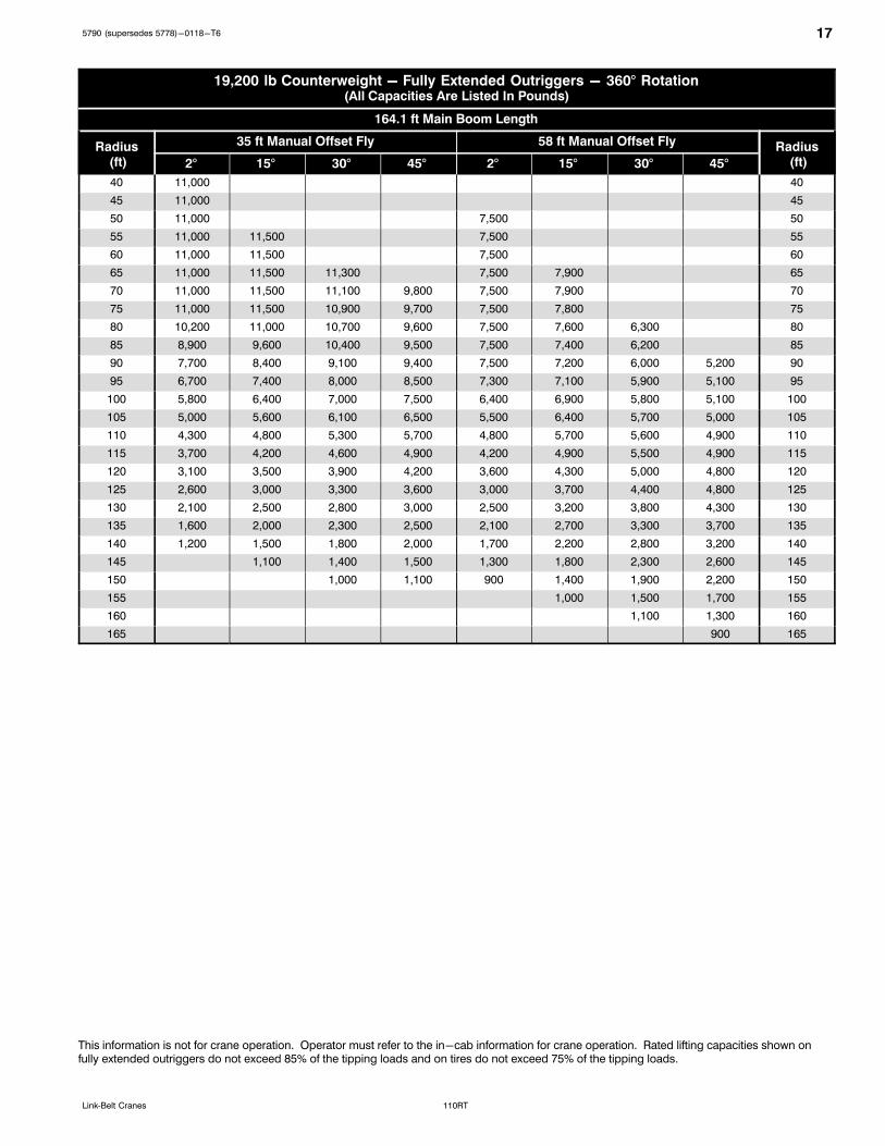
19,200 lb Counterweight - Fully Extended Outriggers - 360° Rotation(All Capacities Are Listed In Pounds)
164.1 ft Main Boom Length
Radius (ft)
35 ft Manual Offset Fly 58 ft Manual Offset Fly Radius (ft)2° 15° 30° 45° 2° 15° 30° 45°
40 11,000 40
45 11,000 45
50 11,000 7,500 50
55 11,000 11,500 7,500 55
60 11,000 11,500 7,500 60
65 11,000 11,500 11,300 7,500 7,900 65
70 11,000 11,500 11,100 9,800 7,500 7,900 70
75 11,000 11,500 10,900 9,700 7,500 7,800 75
80 10,200 11,000 10,700 9,600 7,500 7,600 6,300 80
85 8,900 9,600 10,400 9,500 7,500 7,400 6,200 85
90 7,700 8,400 9,100 9,400 7,500 7,200 6,000 5,200 90
95 6,700 7,400 8,000 8,500 7,300 7,100 5,900 5,100 95
100 5,800 6,400 7,000 7,500 6,400 6,900 5,800 5,100 100
105 5,000 5,600 6,100 6,500 5,500 6,400 5,700 5,000 105
110 4,300 4,800 5,300 5,700 4,800 5,700 5,600 4,900 110
115 3,700 4,200 4,600 4,900 4,200 4,900 5,500 4,900 115
120 3,100 3,500 3,900 4,200 3,600 4,300 5,000 4,800 120
125 2,600 3,000 3,300 3,600 3,000 3,700 4,400 4,800 125
130 2,100 2,500 2,800 3,000 2,500 3,200 3,800 4,300 130
135 1,600 2,000 2,300 2,500 2,100 2,700 3,300 3,700 135
140 1,200 1,500 1,800 2,000 1,700 2,200 2,800 3,200 140
145 1,100 1,400 1,500 1,300 1,800 2,300 2,600 145
150 1,000 1,100 900 1,400 1,900 2,200 150
155 1,000 1,500 1,700 155
160 1,100 1,300 160
165 900 165
This information is not for crane operation. Operator must refer to the in-cab information for crane operation. Rated lifting capacities shown onfully extended outriggers do not exceed 85% of the tipping loads and on tires do not exceed 75% of the tipping loads.
18 5790 (supersedes 5778)-0118-T6
110RT Link‐Belt Cranes
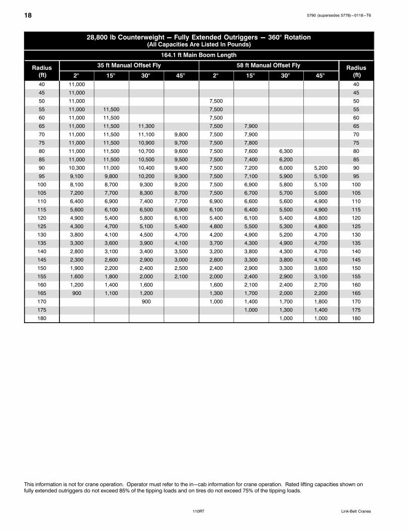
28,800 lb Counterweight - Fully Extended Outriggers - 360° Rotation(All Capacities Are Listed In Pounds)
164.1 ft Main Boom Length
Radius (ft)
35 ft Manual Offset Fly 58 ft Manual Offset Fly Radius (ft)2° 15° 30° 45° 2° 15° 30° 45°
40 11,000 40
45 11,000 45
50 11,000 7,500 50
55 11,000 11,500 7,500 55
60 11,000 11,500 7,500 60
65 11,000 11,500 11,300 7,500 7,900 65
70 11,000 11,500 11,100 9,800 7,500 7,900 70
75 11,000 11,500 10,900 9,700 7,500 7,800 75
80 11,000 11,500 10,700 9,600 7,500 7,600 6,300 80
85 11,000 11,500 10,500 9,500 7,500 7,400 6,200 85
90 10,300 11,000 10,400 9,400 7,500 7,200 6,000 5,200 90
95 9,100 9,800 10,200 9,300 7,500 7,100 5,900 5,100 95
100 8,100 8,700 9,300 9,200 7,500 6,900 5,800 5,100 100
105 7,200 7,700 8,300 8,700 7,500 6,700 5,700 5,000 105
110 6,400 6,900 7,400 7,700 6,900 6,600 5,600 4,900 110
115 5,600 6,100 6,500 6,900 6,100 6,400 5,500 4,900 115
120 4,900 5,400 5,800 6,100 5,400 6,100 5,400 4,800 120
125 4,300 4,700 5,100 5,400 4,800 5,500 5,300 4,800 125
130 3,800 4,100 4,500 4,700 4,200 4,900 5,200 4,700 130
135 3,300 3,600 3,900 4,100 3,700 4,300 4,900 4,700 135
140 2,800 3,100 3,400 3,500 3,200 3,800 4,300 4,700 140
145 2,300 2,600 2,900 3,000 2,800 3,300 3,800 4,100 145
150 1,900 2,200 2,400 2,500 2,400 2,900 3,300 3,600 150
155 1,600 1,800 2,000 2,100 2,000 2,400 2,900 3,100 155
160 1,200 1,400 1,600 1,600 2,100 2,400 2,700 160
165 900 1,100 1,200 1,300 1,700 2,000 2,200 165
170 900 1,000 1,400 1,700 1,800 170
175 1,000 1,300 1,400 175
180 1,000 1,000 180
This information is not for crane operation. Operator must refer to the in-cab information for crane operation. Rated lifting capacities shown onfully extended outriggers do not exceed 85% of the tipping loads and on tires do not exceed 75% of the tipping loads.

195790 (supersedes 5778)-0118-T6
110RTLink‐Belt Cranes
Main Boom Lift Capacity Charts - On Tires
19,200 lb Counterweight - On Tires - Stationary - Boom Centered Over Front Between Tire Tracks(All Capacities Are Listed In Pounds)
Radius(ft)
Boom Length (ft) Radius(ft)38.3 50.0 61.7 75.0 86.0 100.0 111.2
12 69,700 12
15 59,100 61,900 15
20 46,500 49,400 42,100 20
25 33,700 37,500 36,800 36,800 25
30 23,600 27,200 29,300 30,200 30,700 30
35 20,600 22,600 23,500 24,000 24,000 35
40 15,900 17,900 18,900 19,300 19,300 19,300 40
45 14,500 15,500 15,900 15,900 15,900 45
50 11,800 12,800 13,300 13,400 13,400 50
55 10,700 11,200 11,300 11,300 55
60 9,000 9,500 9,600 9,600 60
65 7,600 8,100 8,200 8,200 65
70 6,900 7,000 7,000 70
75 5,900 5,900 6,000 75
80 5,100 5,100 80
85 4,300 4,300 85
90 3,600 3,700 90
95 3,100 95
100 2,600 100
This information is not for crane operation. Operator must refer to the in-cab information for crane operation. Rated lifting capacities shown onfully extended outriggers do not exceed 85% of the tipping loads and on tires do not exceed 75% of the tipping loads.

20 5790 (supersedes 5778)-0118-T6
110RT Link‐Belt Cranes
19,200 lb Counterweight - On Tires - Pick & Carry (Creep) - Boom Centered Over Front(All Capacities Are Listed In Pounds)
Radius(ft)
Boom Length (ft) Radius(ft)38.3 50.0 61.7 75.0 86.0 100.0 111.2
12 67,600 12
15 56,400 58,900 15
20 43,100 45,800 42,100 20
25 33,700 36,700 36,800 36,800 25
30 23,600 27,200 29,300 30,200 30,700 30
35 20,600 22,600 23,500 24,000 24,000 35
40 15,900 17,900 18,900 19,300 19,300 19,300 40
45 14,500 15,500 15,900 15,900 15,900 45
50 11,800 12,800 13,300 13,400 13,400 50
55 10,700 11,200 11,300 11,300 55
60 9,000 9,500 9,600 9,600 60
65 7,600 8,100 8,200 8,200 65
70 6,900 7,000 7,000 70
75 5,900 5,900 6,000 75
80 5,100 5,100 80
85 4,300 4,300 85
90 3,600 3,700 90
95 3,100 95
100 2,600 100
19,200 lb Counterweight - On Tires - Stationary - 360° Rotation(All Capacities Are Listed In Pounds)
Radius(ft)
Boom Length (ft) Radius(ft)38.3 50.0 61.7 75.0 86.0 100.0 111.2
15 35,100 15
20 20,800 24,200 20
25 13,100 16,300 18,200 25
30 8,200 11,400 13,300 14,200 30
35 8,000 9,800 10,800 11,300 35
40 5,600 7,400 8,300 8,800 40
45 5,500 6,400 6,900 7,000 45
50 4,000 4,900 5,400 5,500 5,500 50
55 3,700 4,200 4,300 4,300 55
60 2,700 3,200 3,300 3,300 60
65 1,900 2,400 2,500 2,500 65
70 1,700 1,800 1,800 70
75 1,200 1,200 75
This information is not for crane operation. Operator must refer to the in-cab information for crane operation. Rated lifting capacities shown onfully extended outriggers do not exceed 85% of the tipping loads and on tires do not exceed 75% of the tipping loads.

215790 (supersedes 5778)-0118-T6
110RTLink‐Belt Cranes
Main Boom Lift Capacity Charts - 85% - Metric
8.8t Counterweight - Fully Extended Outriggers - 360° Rotation(All Capacities Are Listed In Kilograms)
Radius(m)
Boom Length (m)Radius
(m)11.6715.24-15.38
18.8-19.21
22.78-23.18
26.21-27.28
30.4833.88-34.94
38.141.82-42.75
45.72 50.02
2.1 100 000* 2.1
2.5 90 000* 2.5
3 73 750 73 350 62 400 3
3.5 67 250 67 900 62 400 3.5
4 61 700 62 450 60 400 54 600 4
4.5 54 750 56 000 56 300 54 600 41 650 4.5
5 48 900 50 200 50 500 50 350 41 650 5
6 40 000 41 250 41 700 41 550 41 100 29 950 22 950 6
7 33 500 34 800 35 250 35 150 34 750 29 950 22 950 7
8 28 550 29 850 30 300 30 250 30 800 29 950 22 950 17 650 11 600 8
9 24 650 26 000 26 450 27 150 27 000 26 650 22 950 17 650 14 050 10 250 9
10 22 900 23 850 24 050 23 900 23 550 22 000 17 650 14 050 10 250 10
12 16 550 17 350 17 550 17 350 17 450 16 700 16 950 14 050 10 250 8 950 12
14 13 200 13 400 13 500 13 350 13 200 12 850 12 500 10 250 8 950 14
16 10 350 10 950 10 700 10 500 10 550 11 100 10 900 10 250 8 950 16
18 9 000 8 650 9 250 9 250 9 050 8 900 8 550 8 250 18
20 7 450 7 650 7 700 7 700 7 500 7 350 7 100 6 800 20
22 6 500 6 550 6 550 6 350 6 200 5 900 5 600 22
24 5 550 5 600 5 600 5 400 5 250 4 950 4 650 24
26 4 750 4 800 4 600 4 450 4 150 3 900 26
28 4 100 4 100 3 900 3 800 3 500 3 250 28
30 3 550 3 350 3 200 2 950 2 650 30
32 2 250 2 850 2 750 2 450 2 200 32
34 2 450 2 300 2 050 1 800 34
36 1 950 1 700 1 450 36
38 1 650 1 350 1 100 38
40 1 050 850 40
42 800 550 42
* Over Front Only
* ASME B30.5 or Special Equipment
This information is not for crane operation. Operator must refer to the in-cab information for crane operation. Rated lifting capacities shown onfully extended outriggers do not exceed 85% of the tipping loads and on tires do not exceed 75% of the tipping loads.

22 5790 (supersedes 5778)-0118-T6
110RT Link‐Belt Cranes
13.2t Counterweight - Fully Extended Outriggers - 360° Rotation(All Capacities Are Listed In Kilograms)
Radius(m)
Boom Length (m)Radius
(m)11.6715.24-15.38
18.8-19.21
22.78-23.18
26.21-27.28
30.4833.88-34.94
38.141.82-42.75
45.72 50.02
2.1 100 000* 2.1
2.5 90 000* 2.5
3 74 550 73 350 62 400 3
3.5 67 950 68 200 62 400 3.5
4 62 350 63 100 60 400 54 600 4
4.5 57 550 58 300 57 100 54 600 41 650 4.5
5 51 750 53 000 53 300 53 100 41 650 5
6 42 350 43 600 44 000 43 900 41 650 29 950 22 950 6
7 35 550 36 850 37 250 37 150 36 750 29 950 22 950 7
8 30 350 31 650 32 100 32 050 31 700 29 950 22 950 17 650 11 600 8
9 26 300 27 650 28 100 28 300 28 600 28 250 22 950 17 650 14 050 10 250 9
10 24 350 24 800 25 500 25 350 25 000 22 000 17 650 14 050 10 250 10
12 19 650 20 350 20 600 20 450 20 100 19 150 17 500 14 050 10 250 8 950 12
14 15 900 16 050 15 850 15 950 15 000 15 450 14 050 10 250 8 950 14
16 12 600 12 850 12 950 12 750 12 600 12 300 11 950 10 250 8 950 16
18 10 500 10 600 10 400 10 300 10 400 10 550 10 250 8 950 18
20 9 150 8 800 8 650 8 700 9 200 9 050 8 700 8 400 20
22 7 450 7 950 8 000 7 800 7 650 7 350 7 100 22
24 6 300 6 950 6 950 6 750 6 600 6 300 6 000 24
26 6 000 6 000 5 800 5 700 5 400 5 100 26
28 5 200 5 250 5 050 4 900 4 650 4 350 28
30 4 600 4 400 4 250 4 000 3 700 30
32 3 200 3 850 3 700 3 450 3 150 32
34 3 350 3 250 2 950 2 700 34
36 2 800 2 550 2 300 36
38 2 450 2 150 1 900 38
40 1 100 1 850 1 600 40
42 1 550 1 300 42
44 1 050 44
46 800 46
* Over Front Only
* ASME B30.5 or Special Equipment
This information is not for crane operation. Operator must refer to the in-cab information for crane operation. Rated lifting capacities shown onfully extended outriggers do not exceed 85% of the tipping loads and on tires do not exceed 75% of the tipping loads.

235790 (supersedes 5778)-0118-T6
110RTLink‐Belt Cranes
Fly Attachment Lift Capacity Charts - 85% - Optional
13.2t Counterweight - Fully Extended Outriggers - 360° Rotation(All Capacities Are Listed In Kilograms)
Radius(m)
Boom Length + 3.0m Manual Offset Fly (2°, 15°, 30° & 45° Offsets)Radius
(m)11.6715.24-15.38
18.8-19.21
22.78-23.18
26.21-27.28
30.4833.88-34.94
38.141.82-42.75
45.72 50.02
3 18 850 19 400 21 600 3
3.5 16 400 16 700 19 400 21 600 3.5
4 16 150 16 500 19 050 21 600 4
4.5 15 950 16 300 16 500 19 200 19 200 4.5
5 15 750 16 100 16 350 18 750 18 950 5
6 15 450 15 800 16 050 16 250 16 350 18 450 18 000 6
7 15 250 15 600 15 850 16 000 16 150 18 100 18 000 7
8 15 150 15 350 15 600 15 800 16 000 16 050 17 750 13 850 9 350 8
9 15 150 15 200 15 450 15 650 15 800 15 900 15 950 13 850 11 600 8 400 9
10 15 150 15 150 15 300 15 500 15 650 15 700 15 800 13 850 11 600 8 400 7 250 10
12 15 150 15 150 15 150 15 300 15 450 15 500 15 600 13 850 11 600 8 400 7 250 12
14 15 150 15 150 15 200 14 950 14 500 14 900 13 850 11 600 8 400 7 250 14
16 10 800 12 500 12 300 12 750 12 550 12 350 12 200 11 600 8 400 7 250 16
18 10 650 10 650 10 600 10 400 10 200 9 900 9 550 8 400 7 250 18
20 8 450 8 900 8 900 8 650 8 450 8 250 8 500 8 400 7 250 20
22 7 500 7 500 7 300 7 200 7 600 7 500 7 150 6 950 22
24 5 800 6 450 6 350 6 700 6 600 6 450 6 150 5 850 24
26 5 550 5 900 5 900 5 700 5 500 5 200 4 950 26
28 3 750 5 200 5 150 4 950 4 750 4 450 4 200 28
30 4 550 4 500 4 300 4 100 3 800 3 550 30
32 3 950 3 750 3 550 3 250 3 000 32
34 3 500 3 250 3 100 2 800 2 500 34
36 2 850 2 650 2 400 2 100 36
38 2 500 2 300 2 000 1 750 38
40 2 000 1 700 1 400 40
42 1 700 1 400 1 150 42
44 1 150 850 44
46 900 650 46
48 450 48
This information is not for crane operation. Operator must refer to the in-cab information for crane operation. Rated lifting capacities shown onfully extended outriggers do not exceed 85% of the tipping loads and on tires do not exceed 75% of the tipping loads.
24 5790 (supersedes 5778)-0118-T6
110RT Link‐Belt Cranes
13.2t Counterweight - Fully Extended Outriggers - 360° Rotation(All Capacities Are Listed In Kilograms)
50.0m Main Boom Length
Radius (m)
10.67m Manual Offset Fly 17.68m Manual Offset FlyRadius
(m)2° 15° 30° 45° 2° 15° 30° 45°
12 5 000 12
14 5 000 14
16 5 000 3 400 16
18 5 000 5 200 3 400 18
20 5 000 5 200 5 100 3 400 3 600 20
22 5 000 5 200 5 000 4 450 3 400 3 600 22
24 5 000 5 200 4 850 4 350 3 400 3 450 24
26 5 000 5 200 4 750 4 300 3 400 3 350 2 800 26
28 4 450 4 750 4 650 4 250 3 400 3 250 2 700 2 350 28
30 3 800 4 100 4 350 4 200 3 400 3 150 2 650 2 300 30
32 3 250 3 500 3 750 3 950 3 400 3 050 2 550 2 250 32
34 2 750 3 000 3 200 3 400 3 000 2 950 2 500 2 250 34
36 2 350 2 550 2 750 2 900 2 550 2 850 2 450 2 200 36
38 2 000 2 150 2 350 2 450 2 200 2 500 2 400 2 150 38
40 1 650 1 800 1 950 2 050 1 850 2 150 2 350 2 150 40
42 1 350 1 500 1 650 1 700 1 550 1 800 2 050 2 100 42
44 1 100 1 200 1 350 1 400 1 300 1 500 1 750 1 900 44
46 850 950 1 050 1 100 1 050 1 250 1 450 1 600 46
48 650 750 800 850 800 1 000 1 200 1 300 48
50 450 500 600 600 800 950 1 050 50
52 450 600 750 800 52
54 400 500 550 54
This information is not for crane operation. Operator must refer to the in-cab information for crane operation. Rated lifting capacities shown onfully extended outriggers do not exceed 85% of the tipping loads and on tires do not exceed 75% of the tipping loads.
255790 (supersedes 5778)-0118-T6
110RTLink‐Belt Cranes
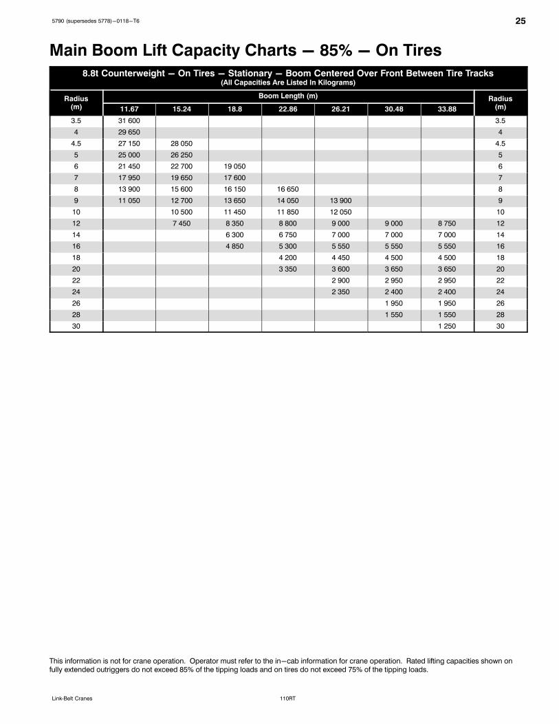
Main Boom Lift Capacity Charts - 85% - On Tires
8.8t Counterweight - On Tires - Stationary - Boom Centered Over Front Between Tire Tracks(All Capacities Are Listed In Kilograms)
Radius(m)
Boom Length (m) Radius(m)11.67 15.24 18.8 22.86 26.21 30.48 33.88
3.5 31 600 3.5
4 29 650 4
4.5 27 150 28 050 4.5
5 25 000 26 250 5
6 21 450 22 700 19 050 6
7 17 950 19 650 17 600 7
8 13 900 15 600 16 150 16 650 8
9 11 050 12 700 13 650 14 050 13 900 9
10 10 500 11 450 11 850 12 050 10
12 7 450 8 350 8 800 9 000 9 000 8 750 12
14 6 300 6 750 7 000 7 000 7 000 14
16 4 850 5 300 5 550 5 550 5 550 16
18 4 200 4 450 4 500 4 500 18
20 3 350 3 600 3 650 3 650 20
22 2 900 2 950 2 950 22
24 2 350 2 400 2 400 24
26 1 950 1 950 26
28 1 550 1 550 28
30 1 250 30
This information is not for crane operation. Operator must refer to the in-cab information for crane operation. Rated lifting capacities shown onfully extended outriggers do not exceed 85% of the tipping loads and on tires do not exceed 75% of the tipping loads.
26 5790 (supersedes 5778)-0118-T6
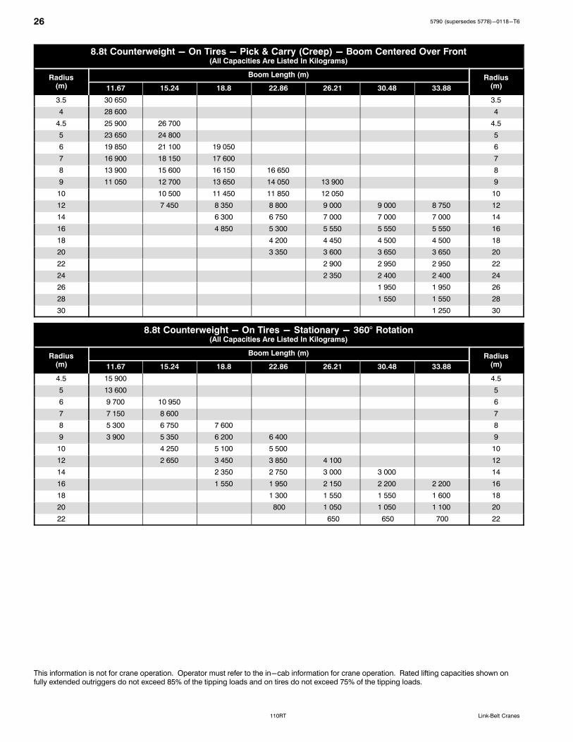
110RT Link‐Belt Cranes
8.8t Counterweight - On Tires - Pick & Carry (Creep) - Boom Centered Over Front(All Capacities Are Listed In Kilograms)
Radius(m)
Boom Length (m) Radius(m)11.67 15.24 18.8 22.86 26.21 30.48 33.88
3.5 30 650 3.5
4 28 600 4
4.5 25 900 26 700 4.5
5 23 650 24 800 5
6 19 850 21 100 19 050 6
7 16 900 18 150 17 600 7
8 13 900 15 600 16 150 16 650 8
9 11 050 12 700 13 650 14 050 13 900 9
10 10 500 11 450 11 850 12 050 10
12 7 450 8 350 8 800 9 000 9 000 8 750 12
14 6 300 6 750 7 000 7 000 7 000 14
16 4 850 5 300 5 550 5 550 5 550 16
18 4 200 4 450 4 500 4 500 18
20 3 350 3 600 3 650 3 650 20
22 2 900 2 950 2 950 22
24 2 350 2 400 2 400 24
26 1 950 1 950 26
28 1 550 1 550 28
30 1 250 30
8.8t Counterweight - On Tires - Stationary - 360° Rotation(All Capacities Are Listed In Kilograms)
Radius(m)
Boom Length (m) Radius(m)11.67 15.24 18.8 22.86 26.21 30.48 33.88
4.5 15 900 4.5
5 13 600 5
6 9 700 10 950 6
7 7 150 8 600 7
8 5 300 6 750 7 600 8
9 3 900 5 350 6 200 6 400 9
10 4 250 5 100 5 500 10
12 2 650 3 450 3 850 4 100 12
14 2 350 2 750 3 000 3 000 14
16 1 550 1 950 2 150 2 200 2 200 16
18 1 300 1 550 1 550 1 600 18
20 800 1 050 1 050 1 100 20
22 650 650 700 22
This information is not for crane operation. Operator must refer to the in-cab information for crane operation. Rated lifting capacities shown onfully extended outriggers do not exceed 85% of the tipping loads and on tires do not exceed 75% of the tipping loads.

275790 (supersedes 5778)-0118-T6
110RTLink‐Belt Cranes
Main Boom Lift Capacity Charts - 75%/ISO - Metric
8.8t Counterweight - Fully Extended Outriggers - 360° Rotation(All Capacities Are Listed In Kilograms)
Radius(m)
Boom Length (m)Radius
(m)11.6715.24-15.38
18.8-19.21
22.78-23.18
26.21-27.28
30.4833.88-34.94
38.141.82-42.75
45.72 50.02
2.1 100 000* 2.1
2.5 90 000* 2.5
3 73 750 73 350 62 400 3
3.5 67 250 67 900 62 400 3.5
4 61 700 62 450 60 400 54 600 4
4.5 54 750 56 000 56 300 54 600 41 650 4.5
5 48 900 50 200 50 500 50 350 41 650 5
6 40 000 41 250 41 700 41 550 41 100 29 950 22 950 6
7 33 500 34 800 35 250 35 150 34 750 29 950 22 950 7
8 28 550 29 850 30 300 30 250 30 800 29 950 22 950 17 650 11 600 8
9 23 200 24 800 25 950 26 100 25 900 25 400 22 950 17 650 14 050 10 250 9
10 20 600 21 350 21 500 21 300 20 850 20 400 17 650 14 050 10 250 10
12 14 600 15 300 15 450 15 550 15 400 15 250 14 900 14 050 10 250 8 950 12
14 11 650 12 200 11 900 11 750 11 700 12 300 11 600 10 250 8 950 14
16 9 350 9 750 9 400 10 000 9 950 9 750 9 600 9 300 8 950 16
18 7 950 8 200 8 150 8 150 7 950 7 800 7 500 7 250 18
20 6 600 6 850 6 850 6 850 6 650 6 500 6 250 6 000 20
22 5 750 5 750 5 750 5 600 5 450 5 200 4 900 22
24 4 850 4 900 4 900 4 750 4 600 4 300 4 000 24
26 4 150 4 200 4 000 3 850 3 550 3 300 26
28 3 550 3 550 3 400 3 250 2 950 2 650 28
30 3 000 2 850 2 700 2 400 2 150 30
32 1 750 2 350 2 250 1 950 1 700 32
34 1 950 1 850 1 600 1 300 34
36 1 500 1 250 1 000 36
38 1 200 900 650 38
40 650 400 40
* Over Front Only
* ASME B30.5 or Special Equipment
This information is not for crane operation. Operator must refer to the in-cab information for crane operation. Rated lifting capacities shown on fullyextended outriggers do not exceed 75%/ISO of the tipping loads and on tires do not exceed 65%/ISO of the tipping loads.

28 5790 (supersedes 5778)-0118-T6
110RT Link‐Belt Cranes
13.2t Counterweight - Fully Extended Outriggers - 360° Rotation(All Capacities Are Listed In Kilograms)
Radius(m)
Boom Length (m)Radius
(m)11.6715.24-15.38
18.8-19.21
22.78-23.18
26.21-27.28
30.4833.88-34.94
38.141.82-42.75
45.72 50.02
2.1 100 000* 2.1
2.5 90 000* 2.5
3 74 550 73 350 62 400 3
3.5 67 950 68 200 62 400 3.5
4 62 350 63 100 60 400 54 600 4
4.5 57 550 58 300 57 100 54 600 41 650 4.5
5 51 750 53 000 53 300 53 100 41 650 5
6 42 350 43 600 44 000 43 900 41 650 29 950 22 950 6
7 35 550 36 850 37 250 37 150 36 750 29 950 22 950 7
8 30 350 31 650 32 100 32 050 31 700 29 950 22 950 17 650 11 600 8
9 26 300 27 650 28 100 28 300 28 600 28 250 22 950 17 650 14 050 10 250 9
10 24 000 24 600 25 200 25 000 24 550 22 000 17 650 14 050 10 250 10
12 17 500 18 250 18 400 18 200 17 800 17 400 17 500 14 050 10 250 8 950 12
14 14 000 14 200 14 300 14 100 14 000 13 700 13 350 10 250 8 950 14
16 11 100 11 300 11 400 11 250 11 100 11 400 11 600 10 250 8 950 16
18 9 650 9 350 9 400 9 550 9 650 9 500 9 250 8 950 18
20 8 050 7 800 8 300 8 300 8 100 7 950 7 650 7 400 20
22 6 900 7 100 7 100 6 900 6 800 6 500 6 300 22
24 6 100 6 100 6 100 5 950 5 800 5 550 5 300 24
26 5 300 5 300 5 150 5 000 4 700 4 450 26
28 4 600 4 600 4 450 4 300 4 000 3 750 28
30 4 000 3 800 3 700 3 400 3 150 30
32 2 650 3 300 3 150 2 900 2 600 32
34 2 850 2 700 2 450 2 200 34
36 2 300 2 050 1 800 36
38 1 950 1 700 1 450 38
40 650 1 350 1 100 40
42 1 100 850 42
44 600 44
* Over Front Only
* ASME B30.5 or Special Equipment
This information is not for crane operation. Operator must refer to the in-cab information for crane operation. Rated lifting capacities shown on fullyextended outriggers do not exceed 75%/ISO of the tipping loads and on tires do not exceed 65%/ISO of the tipping loads.

295790 (supersedes 5778)-0118-T6
110RTLink‐Belt Cranes
Fly Attachment Lift Capacity Charts - 75%/ISO - Optional
13.2t Counterweight - Fully Extended Outriggers - 360° Rotation(All Capacities Are Listed In Kilograms)
Radius(m)
Boom Length + 3.0m Manual Offset Fly (2°, 15°, 30° & 45° Offsets)Radius
(m)11.6715.24-15.38
18.8-19.21
22.78-23.18
26.21-27.28
30.4833.88-34.94
38.141.82-42.75
45.72 50.02
3 18 850 19 400 21 600 3
3.5 16 400 16 700 19 400 21 600 3.5
4 16 150 16 500 19 050 21 600 4
4.5 15 950 16 300 16 500 19 200 19 200 4.5
5 15 750 16 100 16 350 18 750 18 950 5
6 15 450 15 800 16 050 16 250 16 350 18 450 18 000 6
7 15 250 15 600 15 850 16 000 16 150 18 100 18 000 7
8 15 150 15 350 15 600 15 800 16 000 16 050 17 750 13 850 9 350 8
9 15 150 15 200 15 450 15 650 15 800 15 900 15 950 13 850 11 600 8 400 9
10 15 150 15 150 15 300 15 500 15 650 15 700 15 800 13 850 11 600 8 400 7 250 10
12 15 150 15 150 15 150 15 300 15 450 15 500 15 600 13 850 11 600 8 400 7 250 12
14 13 800 13 900 13 650 13 900 13 850 13 750 13 600 11 600 8 400 7 250 14
16 10 800 11 450 11 450 11 450 11 250 11 050 10 750 10 450 8 400 7 250 16
18 9 400 9 400 9 400 9 150 9 000 8 850 9 100 8 400 7 250 18
20 7 450 7 850 7 800 7 600 7 750 7 950 7 800 7 500 7 250 20
22 6 900 6 650 6 850 7 000 6 800 6 650 6 350 6 100 22
24 5 100 5 700 6 050 6 000 5 800 5 650 5 400 5 100 24
26 5 200 5 250 5 200 5 000 4 850 4 550 4 250 26
28 3 100 4 600 4 550 4 300 4 150 3 850 3 550 28
30 4 000 3 950 3 700 3 550 3 250 2 950 30
32 3 400 3 200 3 000 2 700 2 450 32
34 2 950 2 750 2 550 2 250 2 000 34
36 2 350 2 200 1 900 1 600 36
38 2 000 1 850 1 550 1 250 38
40 1 550 1 250 950 40
42 1 250 950 700 42
44 700 450 44
46 500 46
This information is not for crane operation. Operator must refer to the in-cab information for crane operation. Rated lifting capacities shown on fullyextended outriggers do not exceed 75%/ISO of the tipping loads and on tires do not exceed 65%/ISO of the tipping loads.

30 5790 (supersedes 5778)-0118-T6
110RT Link‐Belt Cranes
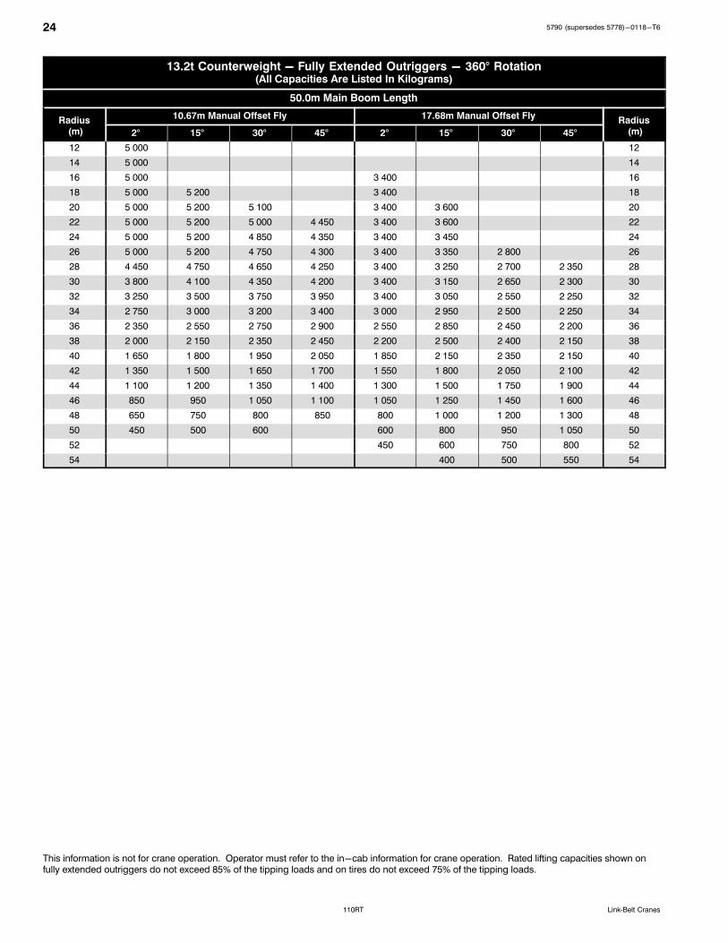
13.2t Counterweight - Fully Extended Outriggers - 360° Rotation(All Capacities Are Listed In Kilograms)
50.0m Main Boom Length
Radius (m)
10.67m Manual Offset Fly 17.68m Manual Offset FlyRadius
(m)2° 15° 30° 45° 2° 15° 30° 45°
12 5 000 12
14 5 000 14
16 5 000 3 400 16
18 5 000 5 200 3 400 18
20 5 000 5 200 5 100 3 400 3 600 20
22 5 000 5 200 5 000 4 450 3 400 3 600 22
24 5 000 5 200 4 850 4 350 3 400 3 450 24
26 4 550 4 900 4 750 4 300 3 400 3 350 2 800 26
28 3 850 4 150 4 450 4 250 3 400 3 250 2 700 2 350 28
30 3 200 3 500 3 800 4 000 3 400 3 150 2 650 2 300 30
32 2 700 2 950 3 200 3 400 2 900 3 050 2 550 2 250 32
34 2 250 2 450 2 700 2 850 2 450 2 850 2 500 2 250 34
36 1 850 2 050 2 250 2 400 2 050 2 400 2 450 2 200 36
38 1 500 1 700 1 850 1 950 1 700 2 000 2 350 2 150 38
40 1 200 1 350 1 500 1 600 1 400 1 700 1 950 2 150 40
42 900 1 050 1 200 1 250 1 100 1 350 1 650 1 800 42
44 650 800 900 950 850 1 100 1 350 1 500 44
46 400 550 650 700 600 850 1 050 1 200 46
48 400 400 600 800 900 48
50 400 550 650 50
52 400 52
This information is not for crane operation. Operator must refer to the in-cab information for crane operation. Rated lifting capacities shown on fullyextended outriggers do not exceed 75%/ISO of the tipping loads and on tires do not exceed 65%/ISO of the tipping loads.

315790 (supersedes 5778)-0118-T6
110RTLink‐Belt Cranes
Main Boom Lift Capacity Charts - 75% - On Tires
8.8t Counterweight - On Tires - Stationary - Boom Centered Over Front Between Tire Tracks(All Capacities Are Listed In Kilograms)
Radius(m)
Boom Length (m) Radius(m)11.67 15.24 18.8 22.86 26.21 30.48 33.88
3.5 31 600 3.5
4 29 650 4
4.5 27 150 28 050 4.5
5 25 000 26 250 5
6 21 450 22 700 19 050 6
7 17 950 19 650 17 600 7
8 13 900 15 600 16 150 16 650 8
9 11 050 12 700 13 650 14 050 13 900 9
10 10 500 11 450 11 850 12 050 10
12 7 450 8 350 8 800 9 000 9 000 8 750 12
14 6 300 6 750 7 000 7 000 7 000 14
16 4 850 5 300 5 550 5 550 5 550 16
18 4 200 4 450 4 500 4 500 18
20 3 350 3 600 3 650 3 650 20
22 2 900 2 950 2 950 22
24 2 350 2 400 2 400 24
26 1 950 1 950 26
28 1 550 1 550 28
30 1 250 30
This information is not for crane operation. Operator must refer to the in-cab information for crane operation. Rated lifting capacities shown on fullyextended outriggers do not exceed 75%/ISO of the tipping loads and on tires do not exceed 65%/ISO of the tipping loads.

32 5790 (supersedes 5778)-0118-T6
110RT Link‐Belt Cranes
8.8t Counterweight - On Tires - Pick & Carry (Creep) - Boom Centered Over Front(All Capacities Are Listed In Kilograms)
Radius(m)
Boom Length (m) Radius(m)11.67 15.24 18.8 22.86 26.21 30.48 33.88
3.5 30 650 3.5
4 28 600 4
4.5 25 900 26 700 4.5
5 23 650 24 800 5
6 19 850 21 100 19 050 6
7 16 900 18 150 17 600 7
8 13 900 15 600 16 150 16 650 8
9 11 050 12 700 13 650 14 050 13 900 9
10 10 500 11 450 11 850 12 050 10
12 7 450 8 350 8 800 9 000 9 000 8 750 12
14 6 300 6 750 7 000 7 000 7 000 14
16 4 850 5 300 5 550 5 550 5 550 16
18 4 200 4 450 4 500 4 500 18
20 3 350 3 600 3 650 3 650 20
22 2 900 2 950 2 950 22
24 2 350 2 400 2 400 24
26 1 950 1 950 26
28 1 550 1 550 28
30 1 250 30
8.8t Counterweight - On Tires - Stationary - 360° Rotation(All Capacities Are Listed In Kilograms)
Radius(m)
Boom Length (m) Radius(m)11.67 15.24 18.8 22.86 26.21 30.48 33.88
3.5 20 050 3.5
4 18 550 4
4.5 16 650 17 550 4.5
5 15 000 16 150 5
6 12 300 13 550 14 000 6
7 10 150 11 450 12 200 7
8 8 450 9 750 10 500 10 900 8
9 7 000 8 350 9 100 9 500 9 550 9
10 7 200 7 950 8 350 8 600 10
12 5 350 6 200 6 600 6 850 6 850 6 750 12
14 4 800 5 250 5 450 5 500 5 550 14
16 3 750 4 150 4 400 4 450 4 500 16
18 3 300 3 550 3 600 3 650 18
20 2 600 2 850 2 900 2 950 20
22 2 300 2 300 2 350 22
24 1 800 1 850 1 850 24
26 1 400 1 450 26
28 1 050 1 050 28
30 750 30
This information is not for crane operation. Operator must refer to the in-cab information for crane operation. Rated lifting capacities shown on fullyextended outriggers do not exceed 75%/ISO of the tipping loads and on tires do not exceed 65%/ISO of the tipping loads.

335790 (supersedes 5778)-0118-T6
110RTLink‐Belt Cranes
This Page Intentionally Blank

34 5790 (supersedes 5778)-0118-T6
110RT Link‐Belt Cranes
This Page Intentionally Blank

355790 (supersedes 5778)-0118-T6
110RTLink‐Belt Cranes
This Page Intentionally Blank

5790 (supersedes 5778)-0118-T6
110RT Link‐Belt Cranes
Link−Belt Cranes Lexington, Kentucky www.linkbelt.com�Link−Belt is a registered trademark. Copyright 2018. We are constantly improving our products and therefore reserve the right to change designs and specifications.