technical data - w. o. grubb
TRANSCRIPT
15471 (supersedes 5431)---0506---J7
RTC---80100 IILink-Belt Cranes
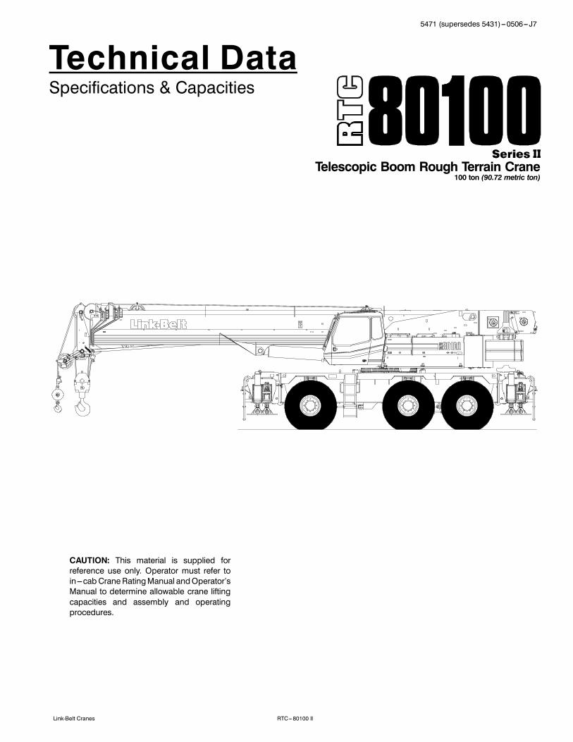
Technical DataSpecifications & Capacities
Telescopic Boom Rough Terrain Crane100 ton (90.72 metric ton)
CAUTION: This material is supplied forreference use only. Operator must refer toin---cab Crane RatingManual andOperator’sManual to determine allowable crane liftingcapacities and assembly and operatingprocedures.

5471 (supersedes 5431)---0506--- J7
RTC---80100 II Link-Belt Cranes
5471 (supersedes 5431)---0506--- J7
RTC---80100 IILink-Belt Cranes
Table Of ContentsBoom, Attachments, and Upper Structure 1. . . . . . . . . . . . . . . . . . . . . . . . . . . . . . . . . . . . . . . . . . . . . . . . . . . .Boom 1. . . . . . . . . . . . . . . . . . . . . . . . . . . . . . . . . . . . . . . . . . . . . . . . . . . . . . . . . . . . . . . . . . . . . . . . . . . . . . . . . . . .Boom Head 1. . . . . . . . . . . . . . . . . . . . . . . . . . . . . . . . . . . . . . . . . . . . . . . . . . . . . . . . . . . . . . . . . . . . . . . . . . . . .Boom Elevation 1. . . . . . . . . . . . . . . . . . . . . . . . . . . . . . . . . . . . . . . . . . . . . . . . . . . . . . . . . . . . . . . . . . . . . . . . . .Auxiliary Lifting Sheave --- Optional 1. . . . . . . . . . . . . . . . . . . . . . . . . . . . . . . . . . . . . . . . . . . . . . . . . . . . . . . . .Hook Blocks and Balls --- Optional 1. . . . . . . . . . . . . . . . . . . . . . . . . . . . . . . . . . . . . . . . . . . . . . . . . . . . . . . . . .Fly --- Optional 1. . . . . . . . . . . . . . . . . . . . . . . . . . . . . . . . . . . . . . . . . . . . . . . . . . . . . . . . . . . . . . . . . . . . . . . . . . .Fly Extensions --- Optional 1. . . . . . . . . . . . . . . . . . . . . . . . . . . . . . . . . . . . . . . . . . . . . . . . . . . . . . . . . . . . . . . . .Operator’s Cab and Controls 1. . . . . . . . . . . . . . . . . . . . . . . . . . . . . . . . . . . . . . . . . . . . . . . . . . . . . . . . . . . . . . . .Swing 2. . . . . . . . . . . . . . . . . . . . . . . . . . . . . . . . . . . . . . . . . . . . . . . . . . . . . . . . . . . . . . . . . . . . . . . . . . . . . . . . . . . .Electrical 2. . . . . . . . . . . . . . . . . . . . . . . . . . . . . . . . . . . . . . . . . . . . . . . . . . . . . . . . . . . . . . . . . . . . . . . . . . . . . . . . .Load Hoist System 3. . . . . . . . . . . . . . . . . . . . . . . . . . . . . . . . . . . . . . . . . . . . . . . . . . . . . . . . . . . . . . . . . . . . . . . . .Load Hoist Performance 3. . . . . . . . . . . . . . . . . . . . . . . . . . . . . . . . . . . . . . . . . . . . . . . . . . . . . . . . . . . . . . . . . . .2M Main and Optional Auxiliary Winches 3. . . . . . . . . . . . . . . . . . . . . . . . . . . . . . . . . . . . . . . . . . . . . . . . . . . .Engine 3. . . . . . . . . . . . . . . . . . . . . . . . . . . . . . . . . . . . . . . . . . . . . . . . . . . . . . . . . . . . . . . . . . . . . . . . . . . . . . . . . . .Drive System 4. . . . . . . . . . . . . . . . . . . . . . . . . . . . . . . . . . . . . . . . . . . . . . . . . . . . . . . . . . . . . . . . . . . . . . . . . . . . . .Fuel Tank 4. . . . . . . . . . . . . . . . . . . . . . . . . . . . . . . . . . . . . . . . . . . . . . . . . . . . . . . . . . . . . . . . . . . . . . . . . . . . . . . . .Hydraulic System 4. . . . . . . . . . . . . . . . . . . . . . . . . . . . . . . . . . . . . . . . . . . . . . . . . . . . . . . . . . . . . . . . . . . . . . . . . .Pump Drive 4. . . . . . . . . . . . . . . . . . . . . . . . . . . . . . . . . . . . . . . . . . . . . . . . . . . . . . . . . . . . . . . . . . . . . . . . . . . . . . .Counterweight 4. . . . . . . . . . . . . . . . . . . . . . . . . . . . . . . . . . . . . . . . . . . . . . . . . . . . . . . . . . . . . . . . . . . . . . . . . . . .Carrier 5. . . . . . . . . . . . . . . . . . . . . . . . . . . . . . . . . . . . . . . . . . . . . . . . . . . . . . . . . . . . . . . . . . . . . . . . . . . . . . . . . . . .General 5. . . . . . . . . . . . . . . . . . . . . . . . . . . . . . . . . . . . . . . . . . . . . . . . . . . . . . . . . . . . . . . . . . . . . . . . . . . . . . . . . . .Outriggers 5. . . . . . . . . . . . . . . . . . . . . . . . . . . . . . . . . . . . . . . . . . . . . . . . . . . . . . . . . . . . . . . . . . . . . . . . . . . . . . . .Steering and Wheel Drive Motors 5. . . . . . . . . . . . . . . . . . . . . . . . . . . . . . . . . . . . . . . . . . . . . . . . . . . . . . . . . . . .Suspension 5. . . . . . . . . . . . . . . . . . . . . . . . . . . . . . . . . . . . . . . . . . . . . . . . . . . . . . . . . . . . . . . . . . . . . . . . . . . . . . .Tires and Wheels 5. . . . . . . . . . . . . . . . . . . . . . . . . . . . . . . . . . . . . . . . . . . . . . . . . . . . . . . . . . . . . . . . . . . . . . . . . .Brakes 5. . . . . . . . . . . . . . . . . . . . . . . . . . . . . . . . . . . . . . . . . . . . . . . . . . . . . . . . . . . . . . . . . . . . . . . . . . . . . . . . . . .Electrical 5. . . . . . . . . . . . . . . . . . . . . . . . . . . . . . . . . . . . . . . . . . . . . . . . . . . . . . . . . . . . . . . . . . . . . . . . . . . . . . . . .Carrier Speeds and Gradeability 5. . . . . . . . . . . . . . . . . . . . . . . . . . . . . . . . . . . . . . . . . . . . . . . . . . . . . . . . . . . . .Hydraulic System 5. . . . . . . . . . . . . . . . . . . . . . . . . . . . . . . . . . . . . . . . . . . . . . . . . . . . . . . . . . . . . . . . . . . . . . . . . .Axle Loads 6. . . . . . . . . . . . . . . . . . . . . . . . . . . . . . . . . . . . . . . . . . . . . . . . . . . . . . . . . . . . . . . . . . . . . . . . . . . . . . . .Transport Configuration and Weights 6. . . . . . . . . . . . . . . . . . . . . . . . . . . . . . . . . . . . . . . . . . . . . . . . . . . . . . . .General Dimensions 7. . . . . . . . . . . . . . . . . . . . . . . . . . . . . . . . . . . . . . . . . . . . . . . . . . . . . . . . . . . . . . . . . . . . . . . .Working Range Diagram 8. . . . . . . . . . . . . . . . . . . . . . . . . . . . . . . . . . . . . . . . . . . . . . . . . . . . . . . . . . . . . . . . . . . .Boom Extend Modes 9. . . . . . . . . . . . . . . . . . . . . . . . . . . . . . . . . . . . . . . . . . . . . . . . . . . . . . . . . . . . . . . . . . . . . . .Main Boom Lift Capacity Charts -- Standard 10. . . . . . . . . . . . . . . . . . . . . . . . . . . . . . . . . . . . . . . . . . . . . . . . .24,000 lb Counterweight --- Fully Extended Outriggers --- 360˚ Rotation 10. . . . . . . . . . . . . . . . . . . . . . . . . . .24,000 lb Counterweight --- On Tires --- Stationary --- Boom Centered Over Rear Between Tire Tracks 1224,000 lb Counterweight --- On Tires --- Pick & Carry (Creep) --- Boom Centered Over Rear 13. . . . . . . . .24,000 lb Counterweight --- On Tires --- Stationary --- 360˚ Rotation 13. . . . . . . . . . . . . . . . . . . . . . . . . . . . . .
5471 (supersedes 5431)---0506--- J7
RTC---80100 II Link-Belt Cranes
Fly Attachment Lift Capacity Charts -- Optional 14. . . . . . . . . . . . . . . . . . . . . . . . . . . . . . . . . . . . . . . . . . . . . . .24,000 lb Counterweight --- Fully Extended Outriggers --- 360˚ Rotation 14. . . . . . . . . . . . . . . . . . . . . . . . . . .150 ft Main Boom Length --- 2˚ Fly Offset 14. . . . . . . . . . . . . . . . . . . . . . . . . . . . . . . . . . . . . . . . . . . . . . . . . . . .150 ft Main Boom Length --- 25˚ Fly Offset 15. . . . . . . . . . . . . . . . . . . . . . . . . . . . . . . . . . . . . . . . . . . . . . . . . . .150 ft Main Boom Length --- 45˚ Fly Offset 16. . . . . . . . . . . . . . . . . . . . . . . . . . . . . . . . . . . . . . . . . . . . . . . . . . .
Main Boom Lift Capacity Charts -- Optional (Metric) 17. . . . . . . . . . . . . . . . . . . . . . . . . . . . . . . . . . . . . . . . . .10 885kg Counterweight --- Fully Extended Outriggers --- 360˚ Rotation 17. . . . . . . . . . . . . . . . . . . . . . . . . .10 885kg Counterweight --- On Tires --- Stationary --- Boom Centered Over Rear Between Tire Tracks 1910 885kg Counterweight --- On Tires --- Pick & Carry (Creep) --- Boom Centered Over Rear 20. . . . . . . . .10 885kg Counterweight --- On Tires --- Stationary --- 360˚ Rotation 20. . . . . . . . . . . . . . . . . . . . . . . . . . . . . .Fly Attachment Lift Capacity Charts -- Optional (Metric) 21. . . . . . . . . . . . . . . . . . . . . . . . . . . . . . . . . . . . . . .10 885kg Counterweight --- Fully Extended Outriggers --- 360˚ Rotation 21. . . . . . . . . . . . . . . . . . . . . . . . . .45.72m Main Boom Length --- 2˚ Fly Offset 21. . . . . . . . . . . . . . . . . . . . . . . . . . . . . . . . . . . . . . . . . . . . . . . . . .45.72m Main Boom Length --- 25˚ Fly Offset 22. . . . . . . . . . . . . . . . . . . . . . . . . . . . . . . . . . . . . . . . . . . . . . . . .45.72m Main Boom Length --- 45˚ Fly Offset 23. . . . . . . . . . . . . . . . . . . . . . . . . . . . . . . . . . . . . . . . . . . . . . . . .

15471 (supersedes 5431)---0506--- J7
RTC---80100 IILink-Belt Cranes
Boom, Attachments, and Upper StructureJ BoomDesign --- Five section, formed construction of extra hightensile steel consisting of one base section and four tele-scoping sections. The first telescoping section extendsindependently by means of one, double---acting, singlestage hydraulic cylinder with integral holding valves. Thesecond telescoping section extends independently bymeans of one, double---acting, single stage hydraulic cylin-der with integral holding valves. The third and fourth sec-tions extend proportionally by means of one, double---act-ing, single stage cylinder with integrated holding valvesand cables.
BoomS 40---150 ft (12.2 ---45.7m) five section full power boomS Three boom extend modes, controlled from the opera-tor’s cab, provide superior capacities by varying the ex-tension of the telescoping sections:S Standard mode is the full power, synchronized modeof telescoping all sections proportionally
S A---max1mode (or mode ‘A1’) extends only the innerand center sections to 95 ft (29m) offering increasedcapacities for in---close, maximum capacity picks
S A---max2mode (or mode ‘A2’) tip, outer and center sec-tions extend to 122.5 ft (37.34m) offering maximumstability
S Mechanical boom angle indicatorS Maximum tip height for each extend mode is:S Standard is 159 ft 6 in (48.6m).S A---max2 is 132 ft 6 in (40.3m)S A---max1 is 105 ft 6 in (32.1m)Boom Wear PadsS Bottom wear pads are universal for all boom sectionsS Top wear pads are universal for all boom sectionsBoom HeadS Six 16.5 in (41.9cm) root diameter nylon sheaves to han-dle up to twelve parts of line
S Easily removable wire rope guardsS Rope dead end lugs on each side of the boom headS Boom head is designed for quick---reeve of the hookblockBoom ElevationS One double acting hydraulic cylinder with integral hold-ing valve
S Boom elevation: ---3˚ to 80˚Auxiliary Lifting Sheave --- OptionalS Single 16.5 in (41.9m) root diameter nylon sheaveS Easily removable wire rope guardsS Does not affect erection of the fly or use of the main headsheaves
Hook Blocks and Balls --- OptionalS 100 ton (90.72mt) 6 sheave, quick---reeve hook block, withsafety latch
S 80 ton (72.57mt) 5 sheave, quick---reeve hook block withsafety latch
S 50 ton (45.36mt) 4 sheave, quick---reeve hook block withsafety latch
S 12 ton (10.89mt) hook ball (swivel) with safety latchFly --- OptionalS 31 ft---55 ft (9.45---16.76m) two piece bi---fold lattice fly,stowable, offsettable to 2˚, 25˚, and 45˚. Maximum tipheight for 31 ft (9.45m) fly is 190 ft (57.9m) and for the 55 ft(16.76m) is 214 ft (65.2m).Fly Extensions --- OptionalS One 15 ft (4.57m) lattice extension to be mounted be-tween the 31 ft (9.45m) and 55 ft (16.76m) fly options.Maximum tip height is 228 ft 6 in (69.6m).
J Operator’s Cab and ControlsEnvironmental Cab --- Fully enclosed, one person cab ofgalvaneal steel structure with acoustical insulationEquipped with:S Tinted and tempered glass windowsS Extra---large fixed front window with windshield wiper andwasher
S Swing up roof window with windshield wiperS Sliding left side door with large fixed windowS Sliding rear and right side windows for ventilationS Six way adjustable, cushioned seat with seat belt andstorage compartment
S Engine dependent warm---water heater with air ducts forfront windshield defroster and cab floor
S Defroster fan for the front windowS Bubble levelS Circulating fanS Adjustable sun visorS Dome lightS Cup holderS Fire extinguisherS Left side viewing mirrorS Two position travel swing lockAir Conditioning --- Optional --- Integral with cab heatingsystem utilizing the same ventilation outletsSteering Column --- Pedestal type with tilt and telescopefunctions for operator comfort. Column includes the follow-ing controls and indicators:Left and right levers include:
S Horn buttonS Turn signal switchS Driving light switchS Forward/Neutral/Reverse direction switch
2 5471 (supersedes 5431)---0506--- J7
RTC---80100 II Link-Belt Cranes
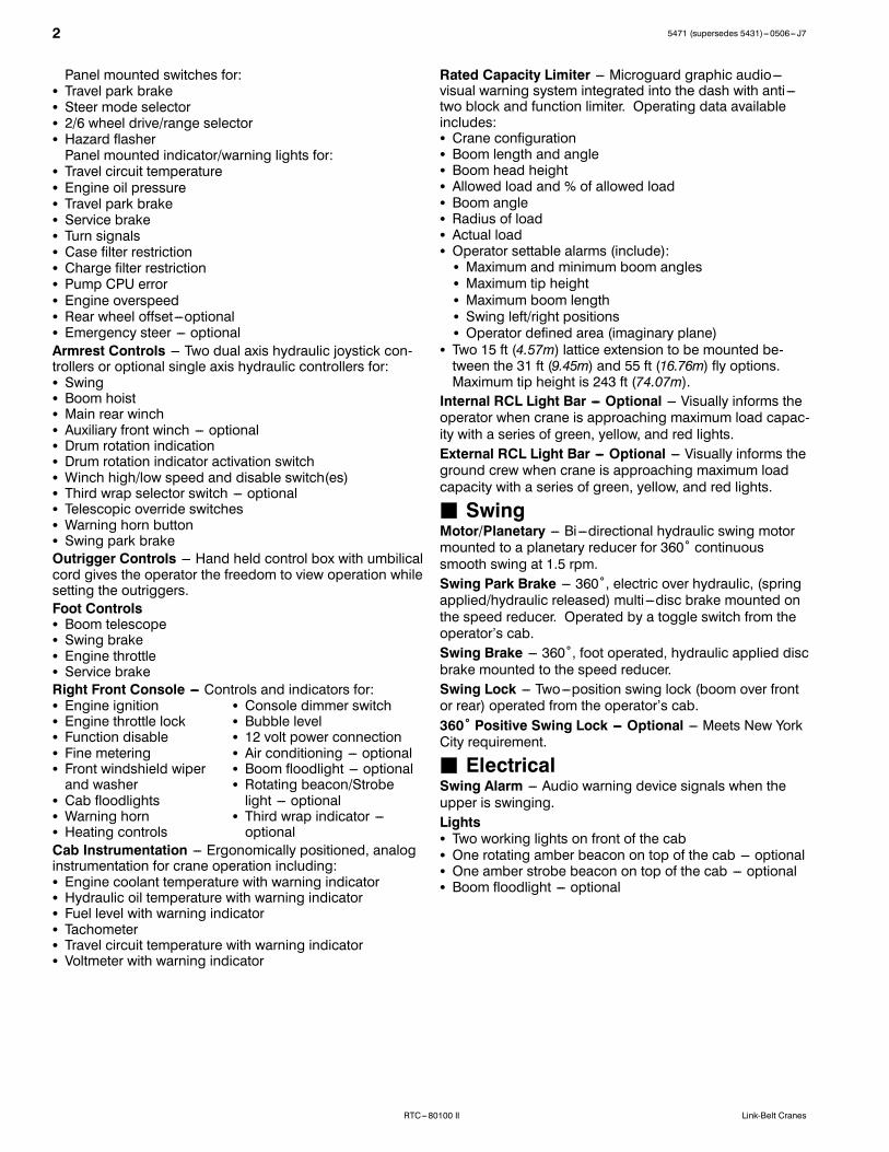
Panel mounted switches for:S Travel park brakeS Steer mode selectorS 2/6 wheel drive/range selectorS Hazard flasherPanel mounted indicator/warning lights for:
S Travel circuit temperatureS Engine oil pressureS Travel park brakeS Service brakeS Turn signalsS Case filter restrictionS Charge filter restrictionS Pump CPU errorS Engine overspeedS Rear wheel offset---optionalS Emergency steer --- optionalArmrest Controls --- Two dual axis hydraulic joystick con-trollers or optional single axis hydraulic controllers for:S SwingS Boom hoistS Main rear winchS Auxiliary front winch --- optionalS Drum rotation indicationS Drum rotation indicator activation switchS Winch high/low speed and disable switch(es)S Third wrap selector switch --- optionalS Telescopic override switchesS Warning horn buttonS Swing park brakeOutrigger Controls --- Hand held control box with umbilicalcord gives the operator the freedom to view operation whilesetting the outriggers.Foot ControlsS Boom telescopeS Swing brakeS Engine throttleS Service brakeRight Front Console --- Controls and indicators for:S Engine ignition S Console dimmer switchS Engine throttle lock S Bubble levelS Function disable S 12 volt power connectionS Fine metering S Air conditioning --- optionalS Front windshield wiper S Boom floodlight --- optionaland washer S Rotating beacon/Strobe
S Cab floodlights light --- optionalS Warning horn S Third wrap indicator ---S Heating controls optionalCab Instrumentation --- Ergonomically positioned, analoginstrumentation for crane operation including:S Engine coolant temperature with warning indicatorS Hydraulic oil temperature with warning indicatorS Fuel level with warning indicatorS TachometerS Travel circuit temperature with warning indicatorS Voltmeter with warning indicator
Rated Capacity Limiter --- Microguard graphic audio---visual warning system integrated into the dash with anti ---two block and function limiter. Operating data availableincludes:S Crane configurationS Boom length and angleS Boom head heightS Allowed load and % of allowed loadS Boom angleS Radius of loadS Actual loadS Operator settable alarms (include):S Maximum and minimum boom anglesS Maximum tip heightS Maximum boom lengthS Swing left/right positionsS Operator defined area (imaginary plane)
S Two 15 ft (4.57m) lattice extension to be mounted be-tween the 31 ft (9.45m) and 55 ft (16.76m) fly options.Maximum tip height is 243 ft (74.07m).Internal RCL Light Bar --- Optional --- Visually informs theoperator when crane is approaching maximum load capac-ity with a series of green, yellow, and red lights.External RCL Light Bar --- Optional --- Visually informs theground crew when crane is approaching maximum loadcapacity with a series of green, yellow, and red lights.
J SwingMotor/Planetary --- Bi ---directional hydraulic swing motormounted to a planetary reducer for 360˚ continuoussmooth swing at 1.5 rpm.Swing Park Brake --- 360˚, electric over hydraulic, (springapplied/hydraulic released) multi ---disc brake mounted onthe speed reducer. Operated by a toggle switch from theoperator’s cab.Swing Brake --- 360˚, foot operated, hydraulic applied discbrake mounted to the speed reducer.Swing Lock --- Two---position swing lock (boom over frontor rear) operated from the operator’s cab.360˚ Positive Swing Lock --- Optional --- Meets New YorkCity requirement.
J ElectricalSwing Alarm --- Audio warning device signals when theupper is swinging.LightsS Two working lights on front of the cabS One rotating amber beacon on top of the cab --- optionalS One amber strobe beacon on top of the cab --- optionalS Boom floodlight --- optional
35471 (supersedes 5431)---0506--- J7
RTC---80100 IILink-Belt Cranes
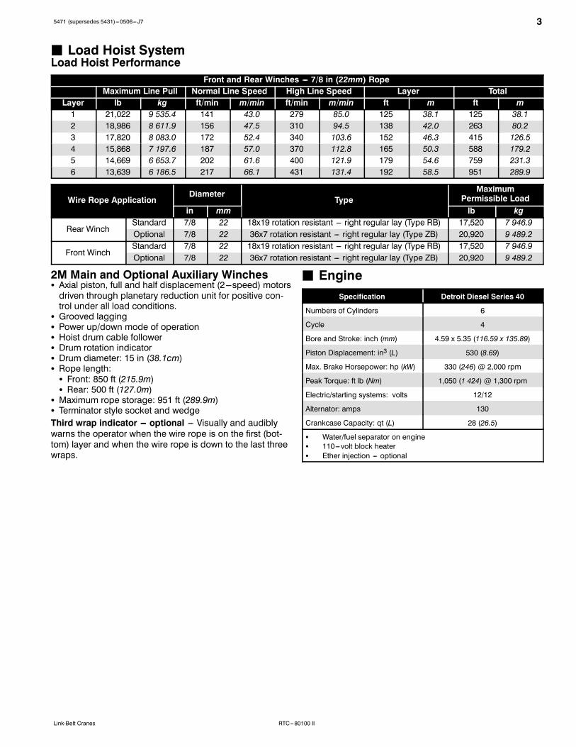
J Load Hoist SystemLoad Hoist Performance
Front and Rear Winches --- 7/8 in (22mm) RopeMaximum Line Pull Normal Line Speed High Line Speed Layer Total
Layer lb kg ft/min m/min ft/min m/min ft m ft m1 21,022 9 535.4 141 43.0 279 85.0 125 38.1 125 38.12 18,986 8 611.9 156 47.5 310 94.5 138 42.0 263 80.23 17,820 8 083.0 172 52.4 340 103.6 152 46.3 415 126.54 15,868 7 197.6 187 57.0 370 112.8 165 50.3 588 179.25 14,669 6 653.7 202 61.6 400 121.9 179 54.6 759 231.36 13,639 6 186.5 217 66.1 431 131.4 192 58.5 951 289.9
Wire Rope ApplicationDiameter
TypeMaximum
Permissible Loadin mm lb kg
Rear WinchStandard 7/8 22 18x19 rotation resistant --- right regular lay (Type RB) 17,520 7 946.9Optional 7/8 22 36x7 rotation resistant --- right regular lay (Type ZB) 20,920 9 489.2
Front WinchStandard 7/8 22 18x19 rotation resistant --- right regular lay (Type RB) 17,520 7 946.9Optional 7/8 22 36x7 rotation resistant --- right regular lay (Type ZB) 20,920 9 489.2
2M Main and Optional Auxiliary WinchesS Axial piston, full and half displacement (2---speed) motorsdriven through planetary reduction unit for positive con-trol under all load conditions.
S Grooved laggingS Power up/down mode of operationS Hoist drum cable followerS Drum rotation indicatorS Drum diameter: 15 in (38.1cm)S Rope length:S Front: 850 ft (215.9m)S Rear: 500 ft (127.0m)
S Maximum rope storage: 951 ft (289.9m)S Terminator style socket and wedgeThird wrap indicator --- optional --- Visually and audiblywarns the operator when the wire rope is on the first (bot-tom) layer and when the wire rope is down to the last threewraps.
J EngineSpecification Detroit Diesel Series 40
Numbers of Cylinders 6
Cycle 4
Bore and Stroke: inch (mm) 4.59 x 5.35 (116.59 x 135.89)
Piston Displacement: in3 (L) 530 (8.69)
Max. Brake Horsepower: hp (kW) 330 (246) @ 2,000 rpm
Peak Torque: ft lb (Nm) 1,050 (1 424) @ 1,300 rpm
Electric/starting systems: volts 12/12
Alternator: amps 130
Crankcase Capacity: qt (L) 28 (26.5)
S Water/fuel separator on engineS 110---volt block heaterS Ether injection --- optional
4 5471 (supersedes 5431)---0506--- J7
RTC---80100 II Link-Belt Cranes
J Drive SystemHydrostatic type consisting of two variable speed pistonpumps supplying hydraulic power to six hydraulic cam lobewheel drive motors computer controlled for smooth andreliable operation.
J Fuel TankOne 95 gal (359.6L) capacity tank
J Hydraulic SystemAll functions are hydraulically powered allowing positiveprecise control with independent or simultaneous operationof all functions.Main PumpsS One, two section gear pump for the boom hoist, tele-scope, and charge circuits.
S Two, closed---loop piston pumps serve as travel pumps.these two pumps supply hydraulic power to the wheelmotors.
S Two, closed---loop piston pumps are mounted to the rearof the two travel pumps. The left pump drives the frontwinch and the right pump drives the optional rear winch.
S One, pressure compensated piston pump mounted tothe rear of the left winch pump supplies hydraulic powerto the outrigger, counterweight removal (optional), oscilla-tion, and travel brake circuits.
S One, single section gear pump mounted to the rear of theright side winch pump supplies hydraulic power to theswing and steering circuits.
Hydraulic Reservoir --- 255 gal (96.5L) capacity equippedwith sight level gauge. Diffuser built in for deaeration. Mag-netic drain plug and large internal magnetFiltrationS One, 7---micron filter located inside hydraulic reservoir,accessible for easy replacement
S One, 7---micron charge filter located next to the reservoirwith an in---cab indicator light
S Two, 10---micron pressure filters located next to the reser-voir with change indicators
S Three, 100 mesh suction strainers located inside the hy-draulic reservoirCounterbalance Valves --- All boom extend cylinders andboom hoist cylinder are equipped with counterbalancevalves to provide load lowering and prevents accidentalload drop when hydraulic power is suddenly reduced.
J Pump DriveAll pumps are mounted on the pump drive gearbox andmechanically driven by the diesel engine.
J CounterweightTotal of 24,000 lb (10 886kg) consisting of two removablecounterweights pinned to the upper with capacities for 0 lb(0kg), 12,000 lb (5 443kg), and 24,000 lb (10 886kg) config-urations.S Optional --- Hydraulic counterweight removal activated bya hand---held controller with enough cable to access thepins on each side of the counterweights.

55471 (supersedes 5431)---0506--- J7
RTC---80100 IILink-Belt Cranes
CarrierJ GeneralS 9 ft 11 in (3.02m) wideS 16 ft 1 in (4.90m) wheelbase (centerline of first axle tocenterline of third axle).Frame --- Box---type, torsion resistant, welded constructionmade of high tensile steel. Equipped with front and reartowing and tie---down lugs, tow connections, and accessladders.
J OutriggersBoxes --- Two removable, double box, front and rearpinned to carrier frame. Hydraulic outrigger pin removal ---optional.Beams and Jacks --- Four single stage beams with Con-fined Area Lifting Capacities (CALCt) provide selectableoutrigger extensions of full, intermediate, and retracted.Hydraulically controlled from the operator’s cab with inte-gral check valves.Pontoons --- Four lightweight, quick release, 26 in (0.66m)diameter, steel pontoons with contact area of 539 in2(3 477cm2) can be stored for road travel in storage rackson the carrier.Main Jack Reaction --- 132,000 lb (59 874kg) force and245 psi (1 689kPa) ground bearing pressure.
J Steering and Wheel Drive MotorsSteering --- Four independent modes consisting of twowheel front, four wheel rear, six wheel, and crab. Eachmode is controlled from the steering wheel and is selectedby a switch in the operator’s cab.Drive --- Three modes: 6 x 2 high, 6 x 2 low, and 6 x 6 foroff highway travelFront Drive Motors --- Steered, driven for 6 x 2 and 6 x 6Rear Drive Motors --- Steered, non---driven for 6 x 2 andsteered, driven for 6 x 6
J SuspensionFront --- Double “A” arms connected to oscillation cylindersthat lockout when the upper structure rotates 3˚ past cent-erlineLeft Rear --- Center and rear wheels mounted on double“A” arms connected to oscillation cylinders that lockoutwhen the upper structure rotates 3˚ past centerline. Os-cillation occurs across left center and left rear wheels.Right Rear --- Center and rear wheels mounted on double“A” arms connected to oscillation cylinders that lockoutwhen the upper structure rotates 3˚ past centerline. Os-cillation occurs across right center and right rear wheels.Ride Height Adjustment --- Suspension can be lowered fortransport using a hand---held controller from the ground.
J Tires and WheelsFront and Rear --- Six (single) 23.5 x 25---2 star radials,earthmover type tires on steel disc wheelsS Spare tires and wheels --- optional
J BrakesService --- Full hydraulic, dual circuit, disc type brakes onall wheel endsParking/Emergency --- Spring loaded type, acting on frontwheel ends
J ElectricalThree batteries provide 12 volt operation and startingLightsS Front lighting includes two main headlights and two park-ing/directional indicators
S Side lighting includes two parking/directional indicatorsper side
S Rear lighting includes two parking/directional indicators,two parking/brake lights, and two reversing lights
S Other equipment includes hazard/warning system
J Carrier Speeds and GradeabilityVariableHydrostaticDrive
Speed Gradeability
Range mph km/h % Grade
6 WD Low 3 4.8 55
2 WD Low 9 14.5 15
2 WD High 18.5 29.8 6
Based on a gross vehicle weight of 123,000 lb (55 792kg).Crane operating angle must not exceed 30˚ (66% grade).
J Hydraulic SystemFiltration --- One, 60---micron, full flow, line filter in thewheel motor case drain circuit. Filter includes an in---cabchange indicator. Accessible for easy filter replacement.
6 5471 (supersedes 5431)---0506--- J7
RTC---80100 II Link-Belt Cranes
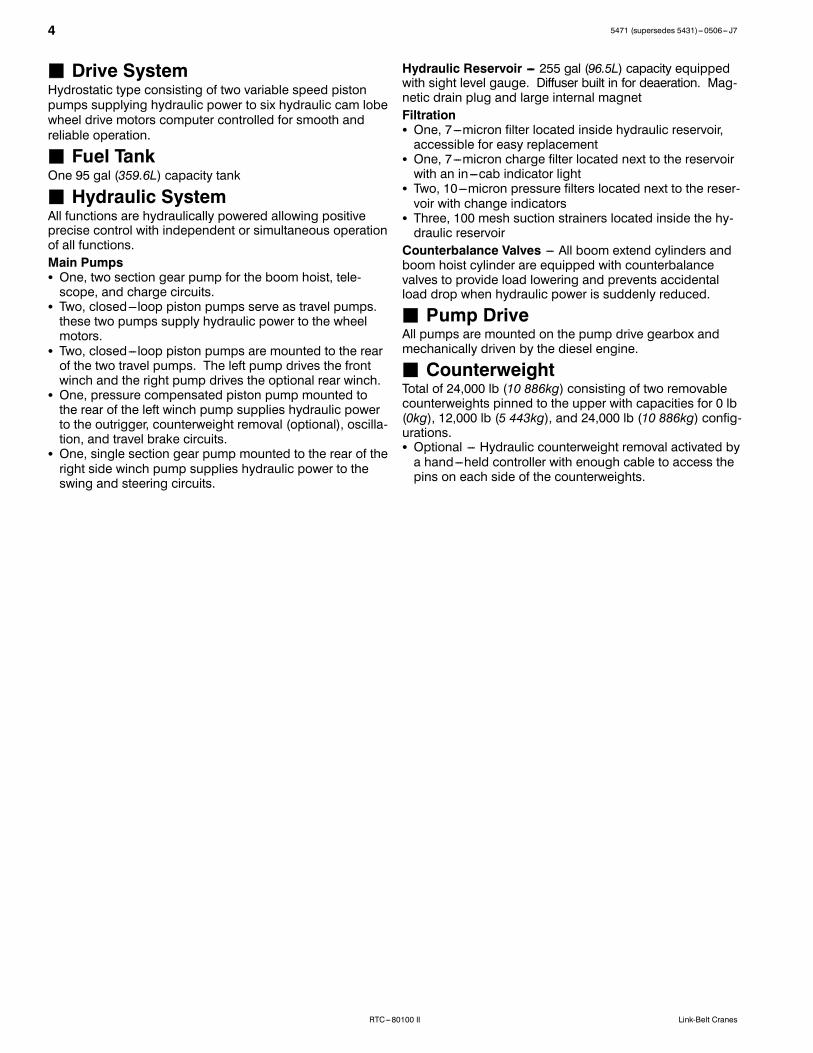
Axle LoadsBase machine with full tank of fueland 24,000 lb (10 886kg) ofcounterweight
Gross VehicleWeight (1)
Upper Facing Front Upper Facing RearFront Axle Rear Axle Group Front Axles Rear Axle Group
lb kg lb kg lb kg lb kg lb kg126,560 57 407 39,742 18 027 86,818 39 380 61,201 27 760 65,359 29 647
Remove outrigger boxes and beams ---17,215 ---7 809 ---6,383 ---2 895 ---10,832 ---4 913 ---6,383 ---2 895 ---10,832 ---4 913Remove main counterweight ---24,182 ---10 969 12,928 5 864 ---37,110 ---16 833 ---31,518 ---14,296 7,336 3 328Cold weather start aid --- ether injec-tor 19 9.5 ---2 ---0.9 21 10 ---2 ---0.9 8 4
Pintle hook, front 20 9 29 13 ---9 ---4 29 13 ---9 ---4Pintle hook, rear 20 9 ---9 ---4 29 13 ---9 ---4 29 13Rear steer indicator 10 4.5 ---2 ---1 12 5 ---2 ---1 12 5Winch roller --- rear winch 110 50 ---82 ---37 192 87 166 75 ---56 ---25Winch roller --- front winch 94 42 ---42 ---4 141 64 119 54 ---25 ---112M auxiliary winch 1,700 771 ---1,143 ---518 284 1,289 2,449 1 110 ---749 ---348500 ft (152m) of 7/8 in (22mm) wirerope on auxiliary winch 862 391 ---579 ---263 1,441 518 1,242 563 ---380 ---172
Air conditioning in operator’s cab 184 83 74 34 110 50 67 30 117 53360˚ swing lock 139 63 35 16 104 47 71 32 68 31Fly brackets to boom base sectionsfor fly options 370 168 497 225 ---127 ---58 ---213 ---97 583 264
31---55 ft (9.45---16.76m) offset fly(stowed) 2,632 1 194 4,223 1 916 ---1,591 ---722 ---2,200 ---998 4,832 2 192
Floodlight to boom base section 10 5 26 12 ---16 ---7 ---18 ---8 28 13100 ton (90.72mt) hook block tofront/rear bumper 1,750 794 2,537 1 151 ---787 ---357 ---1,192 ---541 2,942 1 334
80 ton (72.57mt) hook block to front/rear bumper 1,411 640 2,046 928 ---635 ---288 ---961 ---436 2,372 1 076
50 ton (45.36mt) hook block to front/rear bumper 1,200 544 1,740 789 ---540 ---244 ---817 ---370 2,017 915
12 ton (10.9mt) hook ball to front/rear bumper 722 327 1,047 475 ---325 ---147 ---492 ---223 1,214 551
Auxiliary lifting sheave 120 54 347 157 ---227 ---103 ---254 ---115 374 170
Tire Maximum Load @ 20 mph (32.2km/h)
23.5R25 57,330 lb (26 004kg)
(1) Adjust gross vehicle weight and axle loading according to component weight.Note: All weights are ±3%.
C
BCrane Weight: 89,984 lb (40 816kg), equipped with:S 40---150 ft (12.19 ---45.72m), five section boomS 80 ton (72.57mt) hook blockS One winch with 850 ft (259.08m) of 7/8 in (22mm) ropeS 31---55 ft (9.45 ---16.76m) bi---fold flyS Winch rollerS Auxiliary armS Air conditioning
Drop Off Load Weight: 44,865 lb (20 350kg)S Two outrigger boxes with tow shacklesS 24,000 lb (10 886kg) counterweightS Rear winch with 500 ft (152.40m) of 7/8 in (22mm) ropeS Winch rollerS 12 ton (10.9mt) hook ball
Axle Group Weights
Empty Truck Wt. Bed Length Steer Drivers Trailer A48,500 lb 32 ft 11,900 lb 58,539 lb 68,045 lb 41 in(22 000kg) (9.75m) (5 398kg) (26 553kg) (30 865kg) (1.04m)
B --- 18 in (0.46m) or 24 in (0.61m)
Normal Suspension Collapsed SuspensionC [with 18 in (0.46m) Trailer] 13 ft 8 in (4.17m) 13 ft 5 in (4.09m)C [with 24 in (0.61m) Trailer] 14 ft 2 in (4.32m) 13 ft 11 in (4.24m)
ATransport Configuration and Weights
75471 (supersedes 5431)---0506--- J7
RTC---80100 IILink-Belt Cranes
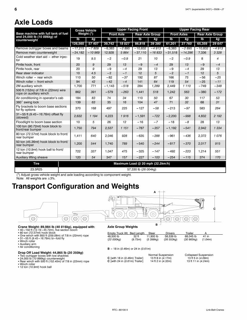
General Dimensions
28”(0.71m)
7’ 7.38” (2.32m)
11’ 2” (3.40m)
18’ 7” (5.66m)
26’ 0” (7.93m)
Full Retraction
Intermediate Extension
Centerline of tires
Full Extension
9’ 11”(3.02m)
12’ 0”(3.65m)
17.75”(0.45m)
10.29”(0.26m)
Turning Radius --- 2 Wheel Steering English MetricWall to wall over carrier 44’ 11” 13.69mWall to wall over boom attachment 55’ 1” 16.79mCurb to curb 41’ 9” 12.73mCenterline of tire 40’ 5” 12.32m
Tail Swing English Metricof counterweight (w/o auxiliary winch) 13’ 9” 3.90mof auxiliary winch 15’ 6” 4.72m
Turning Radius --- 6 Wheel Steering English MetricWall to wall over carrier 25’ 6” 7.77mWall to wall over boom attachment 37’ 8” 11.48mCurb to curb 22’ 3” 6.79mCenterline of tire 20’ 10” 6.35m
L
13.75”(0.35m)
47’ 10”(14.58m)
40’ 1.63”(12.23m)
12’ 11.63”(3.95m)
7’ 1.88”(2.18m) 5’ 10.5”
(1.79m)
2’ 5”(0.73m)
27_
15_
15’ 4.88”(4.70m)
13’ 0”(3.96m)
15’ 4.88”(4.70m)
13’ 0”(3.96m)
8’ 0.5”(2.45m)
8’ 0.5”(2.45m)
15_
2’ 0” (0.61m)
12’ 2.5”(3.71m)
8’ 6.56” (2.61m)
w/o outrigger box --- 12’ 4.88” (3.68m)w/o outrigger box --- 12’ 4.88” (3.68m)
C Rotation
13’ 3.38” (4.05m)
13’ 9” (4.19m)15’ 2” (4.62m)
27_
1’ 8.5”(0.52m)
8 5471 (supersedes 5431)---0506--- J7
RTC---80100 II Link-Belt Cranes
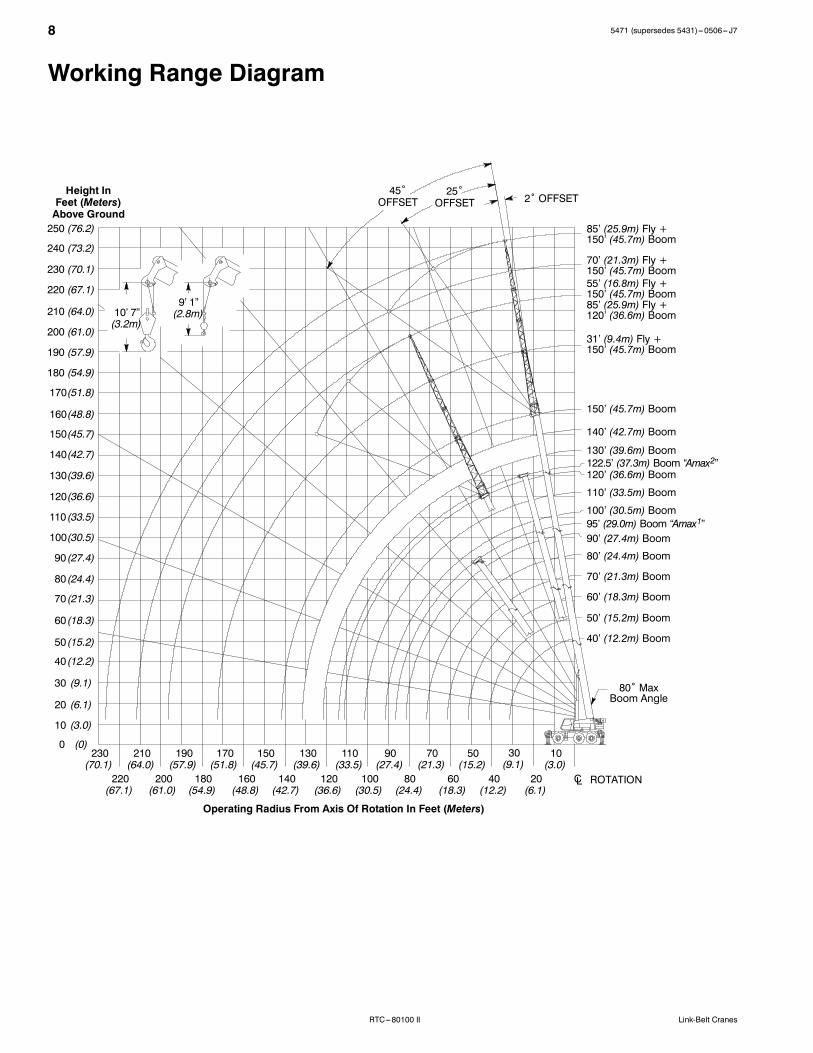
Working Range Diagram
2˚ OFFSET25˚
OFFSET
10
2040
50
60
70
80
90
100
30110130
120
170
160
150
140
Operating Radius From Axis Of Rotation In Feet (Meters)
Height InFeet (Meters)Above Ground
(3.0)
(6.1)(12.2)
(15.2)
(18.3)
(21.3)
(24.4)
(27.4)
(30.5)
(9.1)(33.5)(39.6)
(36.6)
(51.8)
(48.8)
(45.7)
(42.7)
180 (54.9)
190 (57.9)
170(51.8)
160(48.8)
150(45.7)
140(42.7)
130(39.6)
120(36.6)
110 (33.5)
100(30.5)
90 (27.4)
80 (24.4)
70 (21.3)
60 (18.3)
50 (15.2)
40 (12.2)
30 (9.1)
20 (6.1)
10 (3.0)
0
85’ (25.9m) Fly +150’ (45.7m) Boom
55’ (16.8m) Fly +150’ (45.7m) Boom85’ (25.9m) Fly +120’ (36.6m) Boom
110’ (33.5m) Boom
100’ (30.5m) Boom
90’ (27.4m) Boom
80’ (24.4m) Boom
70’ (21.3m) Boom
60’ (18.3m) Boom
50’ (15.2m) Boom
80˚ MaxBoom Angle
200 (61.0)
210 (64.0)
120’ (36.6m) Boom
ROTATIONCL
45˚OFFSET
(0)
220 (67.1)
230 (70.1)
240 (73.2)
250 (76.2)
70’ (21.3m) Fly +150’ (45.7m) Boom
31’ (9.4m) Fly +150’ (45.7m) Boom
150’ (45.7m) Boom
140’ (42.7m) Boom
130’ (39.6m) Boom122.5’ (37.3m) Boom “Amax2”
95’ (29.0m) Boom “Amax1”
40’ (12.2m) Boom
180(54.9)
190(57.9)
200(61.0)
210(64.0)
220(67.1)
230(70.1)
10’ 7”(3.2m)
9’ 1”(2.8m)
95471 (supersedes 5431)---0506--- J7
RTC---80100 IILink-Belt Cranes
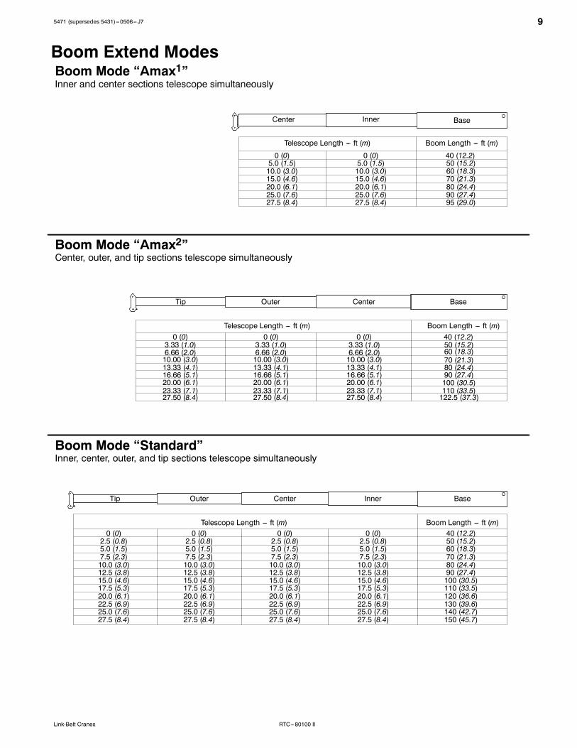
Boom Extend ModesBoom Mode “Amax1”
Boom Mode “Amax2”
Inner and center sections telescope simultaneously
Center, outer, and tip sections telescope simultaneously
Boom Mode “Standard”Inner, center, outer, and tip sections telescope simultaneously
BaseInnerCenterOuterTip
BaseCenterOuterTip
BaseInnerCenter
0 (0)5.0 (1.5)10.0 (3.0)15.0 (4.6)20.0 (6.1)25.0 (7.6)27.5 (8.4)
Boom Length --- ft (m)Telescope Length --- ft (m)
Telescope Length --- ft (m)
Boom Length --- ft (m)Telescope Length --- ft (m)
40 (12.2)50 (15.2)60 (18.3)70 (21.3)80 (24.4)90 (27.4)95 (29.0)
0 (0)3.33 (1.0)6.66 (2.0)10.00 (3.0)13.33 (4.1)16.66 (5.1)20.00 (6.1)23.33 (7.1)27.50 (8.4)
40 (12.2)50 (15.2)60 (18.3)70 (21.3)80 (24.4)90 (27.4)100 (30.5)110 (33.5)122.5 (37.3)
0 (0)2.5 (0.8)5.0 (1.5)7.5 (2.3)10.0 (3.0)12.5 (3.8)15.0 (4.6)17.5 (5.3)20.0 (6.1)22.5 (6.9)25.0 (7.6)27.5 (8.4)
0 (0)5.0 (1.5)10.0 (3.0)15.0 (4.6)20.0 (6.1)25.0 (7.6)27.5 (8.4)
0 (0)3.33 (1.0)6.66 (2.0)10.00 (3.0)13.33 (4.1)16.66 (5.1)20.00 (6.1)23.33 (7.1)27.50 (8.4)
0 (0)3.33 (1.0)6.66 (2.0)10.00 (3.0)13.33 (4.1)16.66 (5.1)20.00 (6.1)23.33 (7.1)27.50 (8.4)
0 (0)2.5 (0.8)5.0 (1.5)7.5 (2.3)10.0 (3.0)12.5 (3.8)15.0 (4.6)17.5 (5.3)20.0 (6.1)22.5 (6.9)25.0 (7.6)27.5 (8.4)
0 (0)2.5 (0.8)5.0 (1.5)7.5 (2.3)10.0 (3.0)12.5 (3.8)15.0 (4.6)17.5 (5.3)20.0 (6.1)22.5 (6.9)25.0 (7.6)27.5 (8.4)
0 (0)2.5 (0.8)5.0 (1.5)7.5 (2.3)10.0 (3.0)12.5 (3.8)15.0 (4.6)17.5 (5.3)20.0 (6.1)22.5 (6.9)25.0 (7.6)27.5 (8.4)
40 (12.2)50 (15.2)60 (18.3)70 (21.3)80 (24.4)90 (27.4)100 (30.5)110 (33.5)120 (36.6)130 (39.6)140 (42.7)150 (45.7)
Boom Length --- ft (m)
10 5471 (supersedes 5431)---0506--- J7
RTC---80100 II Link-Belt Cranes
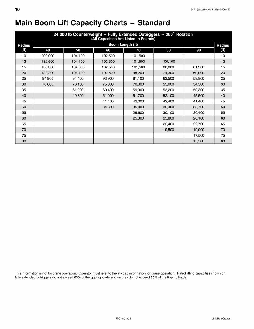
Main Boom Lift Capacity Charts -- Standard24,000 lb Counterweight -- Fully Extended Outriggers -- 360˚ Rotation
(All Capacities Are Listed In Pounds)
Radius(ft)
Boom Length (ft) Radius(ft)40 50 60 70 80 90
10 200,000 104,100 102,500 101,500 1012 182,500 104,100 102,500 101,500 100,100 1215 158,300 104,000 102,500 101,500 88,800 81,900 1520 122,200 104,100 102,500 95,200 74,300 69,900 2025 94,900 94,400 93,900 81,100 63,500 59,800 2530 76,600 76,100 75,800 70,300 55,000 54,500 3035 61,200 60,400 59,900 53,200 50,300 3540 49,800 51,000 51,700 52,100 45,500 4045 41,400 42,000 42,400 41,400 4550 34,300 35,000 35,400 35,700 5055 29,600 30,100 30,400 5560 25,300 25,800 26,100 6065 22,400 22,700 6570 19,500 19,900 7075 17,500 7580 15,500 80
This information is not for crane operation. Operator must refer to the in---cab information for crane operation. Rated lifting capacities shown onfully extended outriggers do not exceed 85% of the tipping loads and on tires do not exceed 75% of the tipping loads.
115471 (supersedes 5431)---0506--- J7
RTC---80100 IILink-Belt Cranes
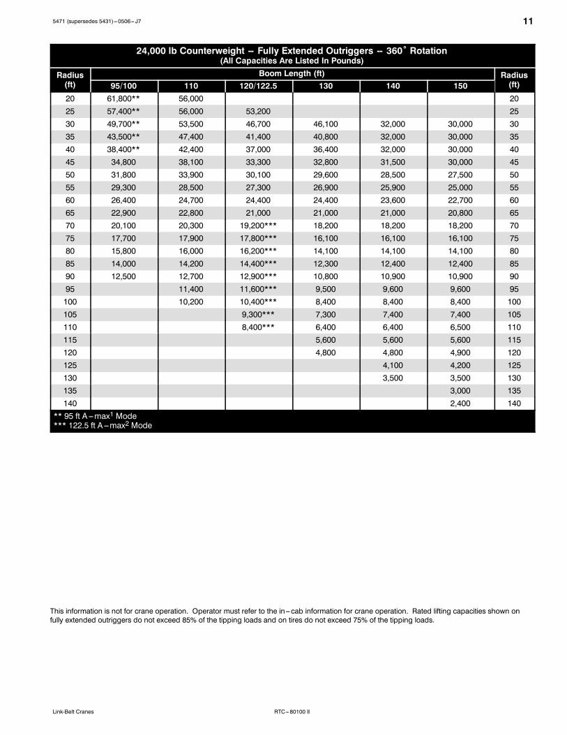
24,000 lb Counterweight -- Fully Extended Outriggers -- 360˚ Rotation(All Capacities Are Listed In Pounds)
Radius(ft)
Boom Length (ft) Radius(ft)95/100 110 120/122.5 130 140 150
20 61,800** 56,000 2025 57,400** 56,000 53,200 2530 49,700** 53,500 46,700 46,100 32,000 30,000 3035 43,500** 47,400 41,400 40,800 32,000 30,000 3540 38,400** 42,400 37,000 36,400 32,000 30,000 4045 34,800 38,100 33,300 32,800 31,500 30,000 4550 31,800 33,900 30,100 29,600 28,500 27,500 5055 29,300 28,500 27,300 26,900 25,900 25,000 5560 26,400 24,700 24,400 24,400 23,600 22,700 6065 22,900 22,800 21,000 21,000 21,000 20,800 6570 20,100 20,300 19,200*** 18,200 18,200 18,200 7075 17,700 17,900 17,800*** 16,100 16,100 16,100 7580 15,800 16,000 16,200*** 14,100 14,100 14,100 8085 14,000 14,200 14,400*** 12,300 12,400 12,400 8590 12,500 12,700 12,900*** 10,800 10,900 10,900 9095 11,400 11,600*** 9,500 9,600 9,600 95100 10,200 10,400*** 8,400 8,400 8,400 100105 9,300*** 7,300 7,400 7,400 105110 8,400*** 6,400 6,400 6,500 110115 5,600 5,600 5,600 115120 4,800 4,800 4,900 120125 4,100 4,200 125130 3,500 3,500 130135 3,000 135140 2,400 140
** 95 ft A---max1 Mode*** 122.5 ft A ---max2 Mode
This information is not for crane operation. Operator must refer to the in---cab information for crane operation. Rated lifting capacities shown onfully extended outriggers do not exceed 85% of the tipping loads and on tires do not exceed 75% of the tipping loads.
12 5471 (supersedes 5431)---0506--- J7
RTC---80100 II Link-Belt Cranes
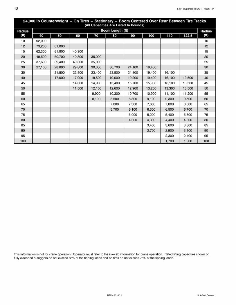
24,000 lb Counterweight -- On Tires -- Stationary -- Boom Centered Over Rear Between Tire Tracks(All Capacities Are Listed In Pounds)
Radius(ft)
Boom Length (ft) Radius(ft)40 50 60 70 80 90 100 110 122.5
10 92,000 1012 73,200 61,800 1215 62,300 61,800 40,300 1520 49,500 50,700 40,300 35,000 2025 37,600 39,400 40,300 35,000 2530 27,100 28,800 29,800 30,300 30,700 24,100 19,400 3035 21,800 22,800 23,400 23,800 24,100 19,400 16,100 3540 17,000 17,900 18,500 19,000 19,200 19,400 16,100 13,500 4045 14,300 14,900 15,400 15,700 15,900 16,100 13,500 4550 11,500 12,100 12,600 12,900 13,200 13,300 13,500 5055 9,900 10,300 10,700 10,900 11,100 11,200 5560 8,100 8,500 8,800 9,100 9,300 9,500 6065 7,000 7,300 7,600 7,800 8,000 6570 5,700 6,100 6,300 6,500 6,700 7075 5,000 5,200 5,400 5,600 7580 4,000 4,300 4,400 4,600 8085 3,400 3,600 3,800 8590 2,700 2,900 3,100 9095 2,300 2,400 95100 1,700 1,900 100
This information is not for crane operation. Operator must refer to the in---cab information for crane operation. Rated lifting capacities shown onfully extended outriggers do not exceed 85% of the tipping loads and on tires do not exceed 75% of the tipping loads.
135471 (supersedes 5431)---0506--- J7
RTC---80100 IILink-Belt Cranes
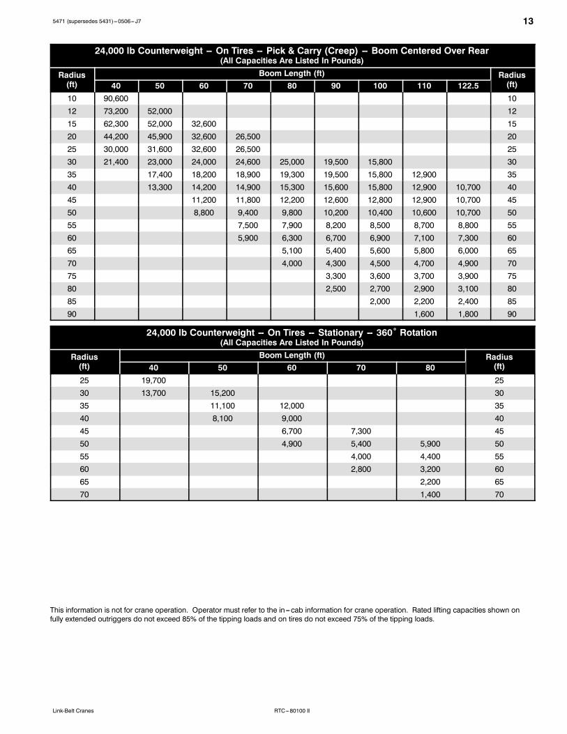
24,000 lb Counterweight -- On Tires -- Pick & Carry (Creep) -- Boom Centered Over Rear(All Capacities Are Listed In Pounds)
Radius(ft)
Boom Length (ft) Radius(ft)40 50 60 70 80 90 100 110 122.5
10 90,600 1012 73,200 52,000 1215 62,300 52,000 32,600 1520 44,200 45,900 32,600 26,500 2025 30,000 31,600 32,600 26,500 2530 21,400 23,000 24,000 24,600 25,000 19,500 15,800 3035 17,400 18,200 18,900 19,300 19,500 15,800 12,900 3540 13,300 14,200 14,900 15,300 15,600 15,800 12,900 10,700 4045 11,200 11,800 12,200 12,600 12,800 12,900 10,700 4550 8,800 9,400 9,800 10,200 10,400 10,600 10,700 5055 7,500 7,900 8,200 8,500 8,700 8,800 5560 5,900 6,300 6,700 6,900 7,100 7,300 6065 5,100 5,400 5,600 5,800 6,000 6570 4,000 4,300 4,500 4,700 4,900 7075 3,300 3,600 3,700 3,900 7580 2,500 2,700 2,900 3,100 8085 2,000 2,200 2,400 8590 1,600 1,800 90
24,000 lb Counterweight -- On Tires -- Stationary -- 360˚ Rotation(All Capacities Are Listed In Pounds)
Radius(ft)
Boom Length (ft) Radius(ft)40 50 60 70 80
25 19,700 2530 13,700 15,200 3035 11,100 12,000 3540 8,100 9,000 4045 6,700 7,300 4550 4,900 5,400 5,900 5055 4,000 4,400 5560 2,800 3,200 6065 2,200 6570 1,400 70
This information is not for crane operation. Operator must refer to the in---cab information for crane operation. Rated lifting capacities shown onfully extended outriggers do not exceed 85% of the tipping loads and on tires do not exceed 75% of the tipping loads.
14 5471 (supersedes 5431)---0506--- J7
RTC---80100 II Link-Belt Cranes
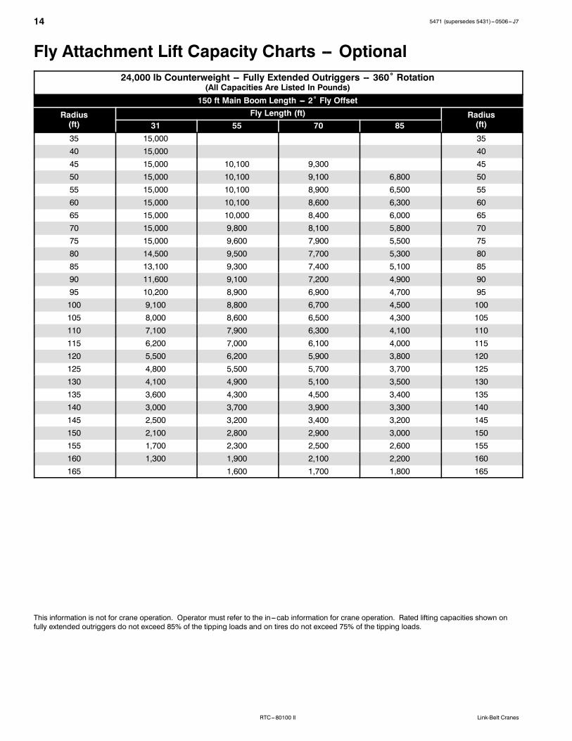
Fly Attachment Lift Capacity Charts -- Optional24,000 lb Counterweight -- Fully Extended Outriggers -- 360˚ Rotation
(All Capacities Are Listed In Pounds)150 ft Main Boom Length --- 2˚ Fly Offset
Radius(ft)
Fly Length (ft) Radius(ft)31 55 70 85
35 15,000 3540 15,000 4045 15,000 10,100 9,300 4550 15,000 10,100 9,100 6,800 5055 15,000 10,100 8,900 6,500 5560 15,000 10,100 8,600 6,300 6065 15,000 10,000 8,400 6,000 6570 15,000 9,800 8,100 5,800 7075 15,000 9,600 7,900 5,500 7580 14,500 9,500 7,700 5,300 8085 13,100 9,300 7,400 5,100 8590 11,600 9,100 7,200 4,900 9095 10,200 8,900 6,900 4,700 95100 9,100 8,800 6,700 4,500 100105 8,000 8,600 6,500 4,300 105110 7,100 7,900 6,300 4,100 110115 6,200 7,000 6,100 4,000 115120 5,500 6,200 5,900 3,800 120125 4,800 5,500 5,700 3,700 125130 4,100 4,900 5,100 3,500 130135 3,600 4,300 4,500 3,400 135140 3,000 3,700 3,900 3,300 140145 2,500 3,200 3,400 3,200 145150 2,100 2,800 2,900 3,000 150155 1,700 2,300 2,500 2,600 155160 1,300 1,900 2,100 2,200 160165 1,600 1,700 1,800 165
This information is not for crane operation. Operator must refer to the in---cab information for crane operation. Rated lifting capacities shown onfully extended outriggers do not exceed 85% of the tipping loads and on tires do not exceed 75% of the tipping loads.
155471 (supersedes 5431)---0506--- J7
RTC---80100 IILink-Belt Cranes
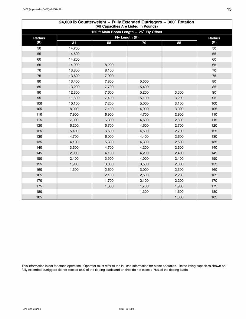
24,000 lb Counterweight -- Fully Extended Outriggers -- 360˚ Rotation(All Capacities Are Listed In Pounds)
150 ft Main Boom Length --- 25˚ Fly Offset
Radius(ft)
Fly Length (ft) Radius(ft)31 55 70 85
50 14,700 5055 14,500 5560 14,200 6065 14,000 8,200 6570 13,800 8,100 7075 13,600 7,900 7580 13,400 7,800 5,500 8085 13,200 7,700 5,400 8590 12,800 7,600 5,200 3,300 9095 11,300 7,400 5,100 3,200 95100 10,100 7,200 5,000 3,100 100105 8,900 7,100 4,900 3,000 105110 7,900 6,900 4,700 2,900 110115 7,000 6,800 4,600 2,800 115120 6,200 6,700 4,600 2,700 120125 5,400 6,500 4,500 2,700 125130 4,700 6,000 4,400 2,600 130135 4,100 5,300 4,300 2,500 135140 3,500 4,700 4,200 2,500 140145 2,900 4,100 4,200 2,400 145150 2,400 3,500 4,000 2,400 150155 1,900 3,000 3,500 2,300 155160 1,500 2,600 3,000 2,300 160165 2,100 2,500 2,200 165170 1,700 2,100 2,200 170175 1,300 1,700 1,900 175180 1,300 1,600 180185 1,300 185
This information is not for crane operation. Operator must refer to the in---cab information for crane operation. Rated lifting capacities shown onfully extended outriggers do not exceed 85% of the tipping loads and on tires do not exceed 75% of the tipping loads.

16 5471 (supersedes 5431)---0506--- J7
RTC---80100 II Link-Belt Cranes
24,000 lb Counterweight -- Fully Extended Outriggers -- 360˚ Rotation(All Capacities Are Listed In Pounds)
150 ft Main Boom Length --- 45˚ Fly Offset
Radius(ft)
Fly Length (ft) Radius(ft)31 55 70 85
60 12,700 6065 12,500 6570 12,400 7075 12,300 7580 12,200 6,600 8085 12,100 6,500 8590 12,000 6,400 9095 11,900 6,300 4,200 95100 10,700 6,200 4,200 100105 9,500 6,100 4,100 105110 8,400 6,100 4,000 2,300 110115 7,400 6,000 4,000 2,300 115120 6,500 5,900 4,000 2,200 120125 5,700 5,900 3,900 2,200 125130 4,900 5,900 3,900 2,200 130135 4,300 5,900 3,900 2,100 135140 5,200 3,800 2,100 140145 4,500 3,800 2,100 145150 3,900 3,800 2,100 150155 3,300 3,800 2,100 155160 2,800 3,500 2,100 160165 2,300 2,900 2,100 165170 2,400 2,100 170175 1,900 2,100 175180 1,500 1,900 180185 1,500 185190 1,200 190
This information is not for crane operation. Operator must refer to the in---cab information for crane operation. Rated lifting capacities shown onfully extended outriggers do not exceed 85% of the tipping loads and on tires do not exceed 75% of the tipping loads.
175471 (supersedes 5431)---0506--- J7
RTC---80100 IILink-Belt Cranes
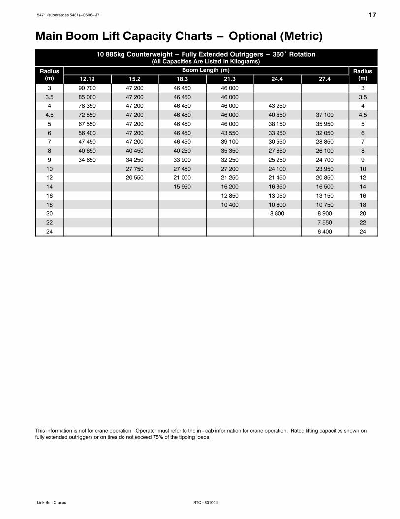
Main Boom Lift Capacity Charts -- Optional (Metric)10 885kg Counterweight -- Fully Extended Outriggers -- 360˚ Rotation
(All Capacities Are Listed In Kilograms)
Radius(m)
Boom Length (m) Radius(m)12.19 15.2 18.3 21.3 24.4 27.4
3 90 700 47 200 46 450 46 000 33.5 85 000 47 200 46 450 46 000 3.54 78 350 47 200 46 450 46 000 43 250 44.5 72 550 47 200 46 450 46 000 40 550 37 100 4.55 67 550 47 200 46 450 46 000 38 150 35 950 56 56 400 47 200 46 450 43 550 33 950 32 050 67 47 450 47 200 46 450 39 100 30 550 28 850 78 40 650 40 450 40 250 35 350 27 650 26 100 89 34 650 34 250 33 900 32 250 25 250 24 700 910 27 750 27 450 27 200 24 100 23 950 1012 20 550 21 000 21 250 21 450 20 850 1214 15 950 16 200 16 350 16 500 1416 12 850 13 050 13 150 1618 10 400 10 600 10 750 1820 8 800 8 900 2022 7 550 2224 6 400 24
This information is not for crane operation. Operator must refer to the in---cab information for crane operation. Rated lifting capacities shown onfully extended outriggers or on tires do not exceed 75% of the tipping loads.
18 5471 (supersedes 5431)---0506--- J7
RTC---80100 II Link-Belt Cranes
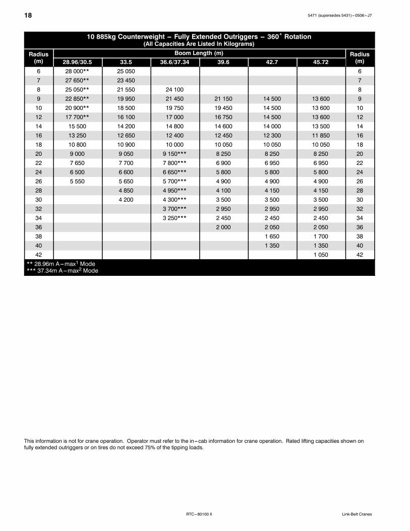
10 885kg Counterweight -- Fully Extended Outriggers -- 360˚ Rotation(All Capacities Are Listed In Kilograms)
Radius(m)
Boom Length (m) Radius(m)28.96/30.5 33.5 36.6/37.34 39.6 42.7 45.72
6 28 000** 25 050 67 27 650** 23 450 78 25 050** 21 550 24 100 89 22 850** 19 950 21 450 21 150 14 500 13 600 910 20 900** 18 500 19 750 19 450 14 500 13 600 1012 17 700** 16 100 17 000 16 750 14 500 13 600 1214 15 500 14 200 14 800 14 600 14 000 13 500 1416 13 250 12 650 12 400 12 450 12 300 11 850 1618 10 800 10 900 10 000 10 050 10 050 10 050 1820 9 000 9 050 9 150*** 8 250 8 250 8 250 2022 7 650 7 700 7 800*** 6 900 6 950 6 950 2224 6 500 6 600 6 650*** 5 800 5 800 5 800 2426 5 550 5 650 5 700*** 4 900 4 900 4 900 2628 4 850 4 950*** 4 100 4 150 4 150 2830 4 200 4 300*** 3 500 3 500 3 500 3032 3 700*** 2 950 2 950 2 950 3234 3 250*** 2 450 2 450 2 450 3436 2 000 2 050 2 050 3638 1 650 1 700 3840 1 350 1 350 4042 1 050 42
** 28.96m A---max1 Mode*** 37.34m A---max2 Mode
This information is not for crane operation. Operator must refer to the in---cab information for crane operation. Rated lifting capacities shown onfully extended outriggers or on tires do not exceed 75% of the tipping loads.
195471 (supersedes 5431)---0506--- J7
RTC---80100 IILink-Belt Cranes
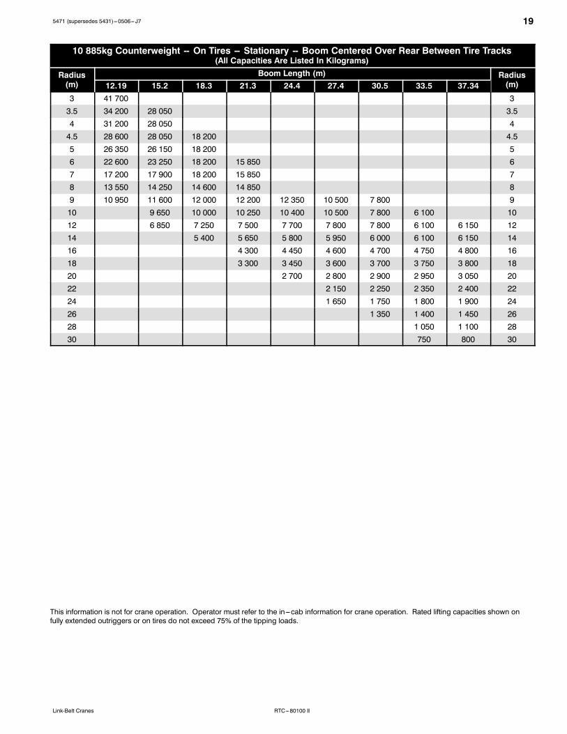
10 885kg Counterweight -- On Tires -- Stationary -- Boom Centered Over Rear Between Tire Tracks(All Capacities Are Listed In Kilograms)
Radius(m)
Boom Length (m) Radius(m)12.19 15.2 18.3 21.3 24.4 27.4 30.5 33.5 37.34
3 41 700 33.5 34 200 28 050 3.54 31 200 28 050 44.5 28 600 28 050 18 200 4.55 26 350 26 150 18 200 56 22 600 23 250 18 200 15 850 67 17 200 17 900 18 200 15 850 78 13 550 14 250 14 600 14 850 89 10 950 11 600 12 000 12 200 12 350 10 500 7 800 910 9 650 10 000 10 250 10 400 10 500 7 800 6 100 1012 6 850 7 250 7 500 7 700 7 800 7 800 6 100 6 150 1214 5 400 5 650 5 800 5 950 6 000 6 100 6 150 1416 4 300 4 450 4 600 4 700 4 750 4 800 1618 3 300 3 450 3 600 3 700 3 750 3 800 1820 2 700 2 800 2 900 2 950 3 050 2022 2 150 2 250 2 350 2 400 2224 1 650 1 750 1 800 1 900 2426 1 350 1 400 1 450 2628 1 050 1 100 2830 750 800 30
This information is not for crane operation. Operator must refer to the in---cab information for crane operation. Rated lifting capacities shown onfully extended outriggers or on tires do not exceed 75% of the tipping loads.
20 5471 (supersedes 5431)---0506--- J7
RTC---80100 II Link-Belt Cranes
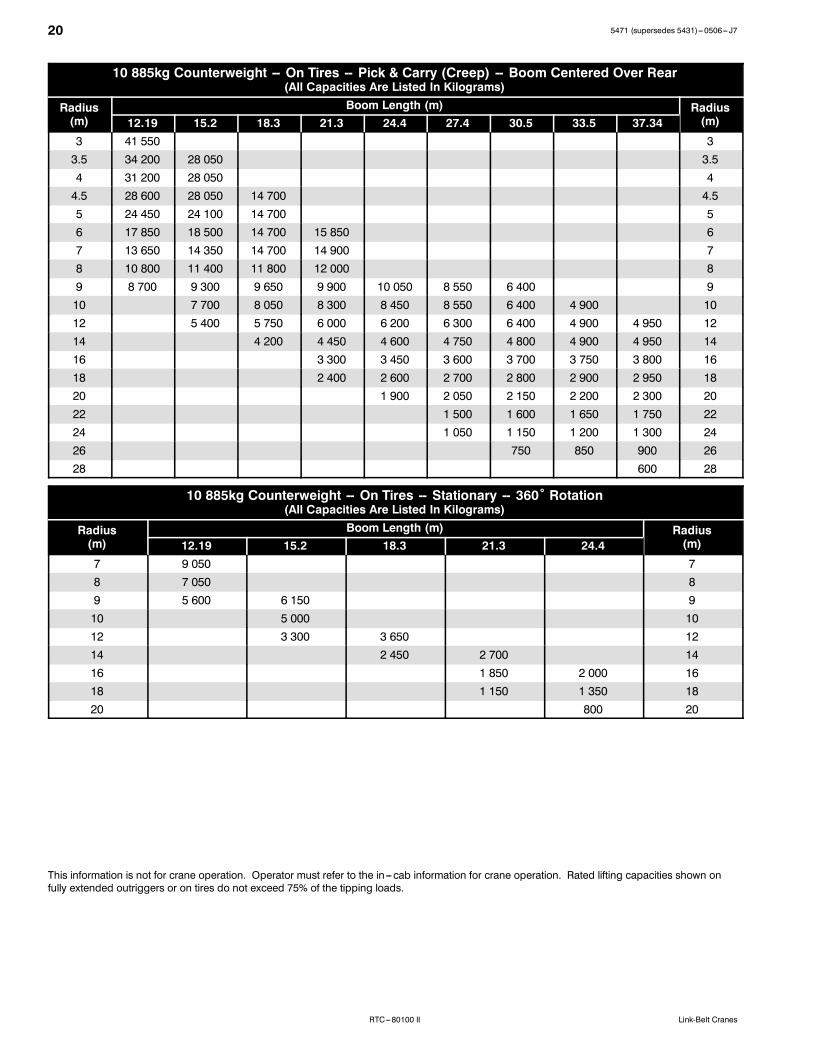
10 885kg Counterweight -- On Tires -- Pick & Carry (Creep) -- Boom Centered Over Rear(All Capacities Are Listed In Kilograms)
Radius(m)
Boom Length (m) Radius(m)12.19 15.2 18.3 21.3 24.4 27.4 30.5 33.5 37.34
3 41 550 33.5 34 200 28 050 3.54 31 200 28 050 44.5 28 600 28 050 14 700 4.55 24 450 24 100 14 700 56 17 850 18 500 14 700 15 850 67 13 650 14 350 14 700 14 900 78 10 800 11 400 11 800 12 000 89 8 700 9 300 9 650 9 900 10 050 8 550 6 400 910 7 700 8 050 8 300 8 450 8 550 6 400 4 900 1012 5 400 5 750 6 000 6 200 6 300 6 400 4 900 4 950 1214 4 200 4 450 4 600 4 750 4 800 4 900 4 950 1416 3 300 3 450 3 600 3 700 3 750 3 800 1618 2 400 2 600 2 700 2 800 2 900 2 950 1820 1 900 2 050 2 150 2 200 2 300 2022 1 500 1 600 1 650 1 750 2224 1 050 1 150 1 200 1 300 2426 750 850 900 2628 600 28
10 885kg Counterweight -- On Tires -- Stationary -- 360˚ Rotation(All Capacities Are Listed In Kilograms)
Radius(m)
Boom Length (m) Radius(m)12.19 15.2 18.3 21.3 24.4
7 9 050 78 7 050 89 5 600 6 150 910 5 000 1012 3 300 3 650 1214 2 450 2 700 1416 1 850 2 000 1618 1 150 1 350 1820 800 20
This information is not for crane operation. Operator must refer to the in---cab information for crane operation. Rated lifting capacities shown onfully extended outriggers or on tires do not exceed 75% of the tipping loads.
215471 (supersedes 5431)---0506--- J7
RTC---80100 IILink-Belt Cranes
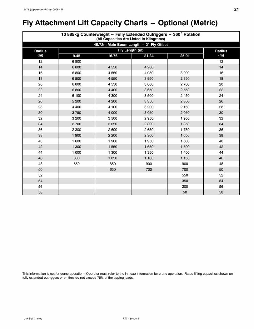
Fly Attachment Lift Capacity Charts -- Optional (Metric)10 885kg Counterweight -- Fully Extended Outriggers -- 360˚ Rotation
(All Capacities Are Listed In Kilograms)45.72m Main Boom Length --- 2˚ Fly Offset
Radius(m)
Fly Length (m) Radius(m)9.45 16.76 21.34 25.91
12 6 800 1214 6 800 4 550 4 200 1416 6 800 4 550 4 050 3 000 1618 6 800 4 550 3 950 2 850 1820 6 800 4 550 3 800 2 700 2022 6 800 4 400 3 650 2 550 2224 6 100 4 300 3 500 2 450 2426 5 200 4 200 3 350 2 300 2628 4 400 4 100 3 200 2 150 2830 3 750 4 000 3 050 2 050 3032 3 200 3 500 2 950 1 950 3234 2 700 3 050 2 800 1 850 3436 2 300 2 600 2 650 1 750 3638 1 900 2 200 2 300 1 650 3840 1 600 1 900 1 950 1 600 4042 1 300 1 550 1 650 1 500 4244 1 000 1 300 1 350 1 400 4446 800 1 050 1 100 1 150 4648 550 850 900 900 4850 650 700 700 5052 550 5254 350 5456 200 5658 50 58
This information is not for crane operation. Operator must refer to the in---cab information for crane operation. Rated lifting capacities shown onfully extended outriggers or on tires do not exceed 75% of the tipping loads.
22 5471 (supersedes 5431)---0506--- J7
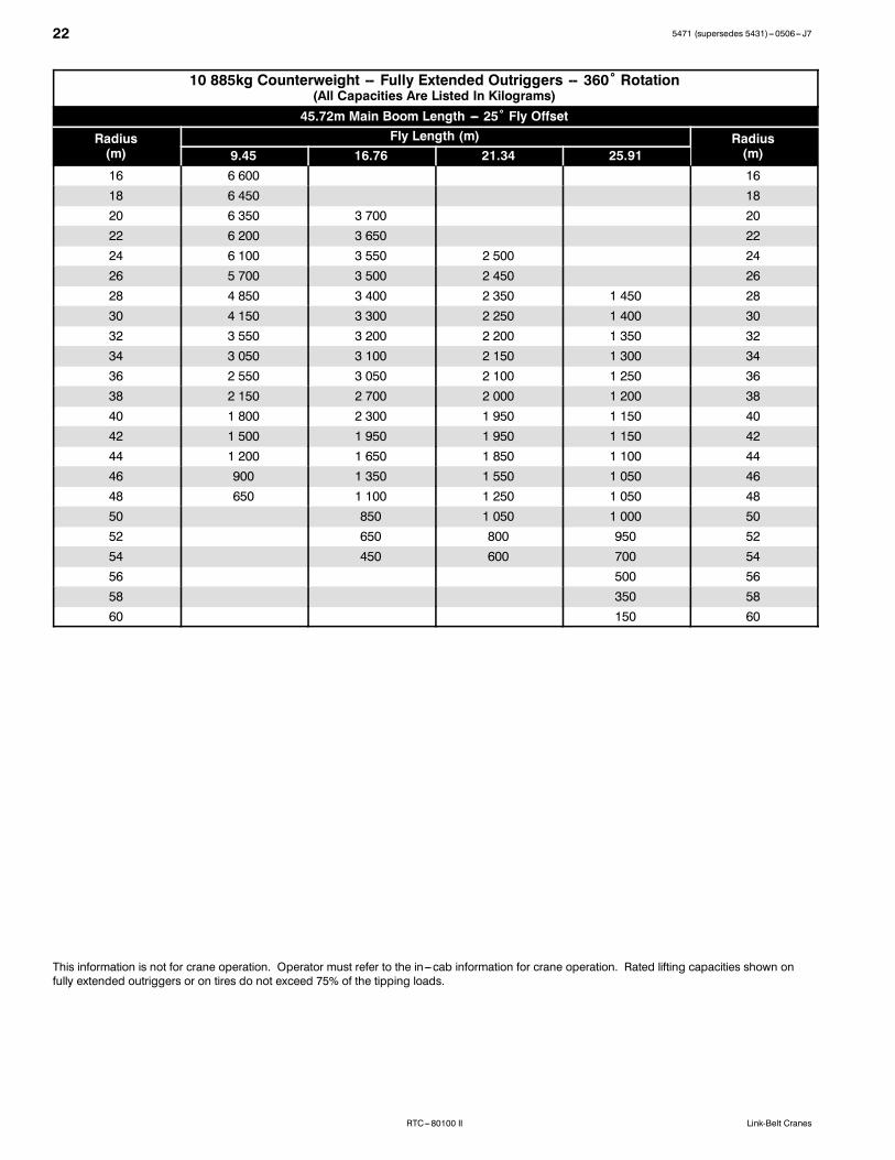
RTC---80100 II Link-Belt Cranes
10 885kg Counterweight -- Fully Extended Outriggers -- 360˚ Rotation(All Capacities Are Listed In Kilograms)45.72m Main Boom Length --- 25˚ Fly Offset
Radius(m)
Fly Length (m) Radius(m)9.45 16.76 21.34 25.91
16 6 600 1618 6 450 1820 6 350 3 700 2022 6 200 3 650 2224 6 100 3 550 2 500 2426 5 700 3 500 2 450 2628 4 850 3 400 2 350 1 450 2830 4 150 3 300 2 250 1 400 3032 3 550 3 200 2 200 1 350 3234 3 050 3 100 2 150 1 300 3436 2 550 3 050 2 100 1 250 3638 2 150 2 700 2 000 1 200 3840 1 800 2 300 1 950 1 150 4042 1 500 1 950 1 950 1 150 4244 1 200 1 650 1 850 1 100 4446 900 1 350 1 550 1 050 4648 650 1 100 1 250 1 050 4850 850 1 050 1 000 5052 650 800 950 5254 450 600 700 5456 500 5658 350 5860 150 60
This information is not for crane operation. Operator must refer to the in---cab information for crane operation. Rated lifting capacities shown onfully extended outriggers or on tires do not exceed 75% of the tipping loads.

235471 (supersedes 5431)---0506--- J7
RTC---80100 IILink-Belt Cranes
10 885kg Counterweight -- Fully Extended Outriggers -- 360˚ Rotation(All Capacities Are Listed In Kilograms)45.72m Main Boom Length --- 45˚ Fly Offset
Radius(m)
Fly Length (m) Radius(m)9.45 16.76 21.34 25.91
18 5 750 1820 5 700 2022 5 600 2224 5 550 3 000 2426 5 500 2 950 2628 5 150 2 850 2830 4 400 2 800 1 900 3032 3 750 2 750 1 850 3234 3 200 2 750 1 850 1 050 3436 2 700 2 700 1 800 1 000 3638 2 300 2 700 1 800 1 000 3840 1 900 2 550 1 750 1 000 4042 1 550 2 150 1 750 950 4244 1 850 1 750 950 4446 1 500 1 750 950 4648 1 200 1 500 950 4850 950 1 200 950 5052 950 950 5254 700 900 5456 650 5658 450 5860 200 60
This information is not for crane operation. Operator must refer to the in---cab information for crane operation. Rated lifting capacities shown onfully extended outriggers or on tires do not exceed 75% of the tipping loads.

5471 (supersedes 5431)---0506--- J7
RTC---80100 II Link-Belt Cranes
Link--Belt Construction Equipment Company Lexington, Kentucky www.linkbelt.comRLink--Belt is a registered trademark. Copyright 2006. We are constantly improving our products and therefore reserve the right to change designs and specifications.