technical innovations in low head hydro - technologies uk · pdf filezcreates extra height to...
TRANSCRIPT
Oliver PaishDerwent Hydro
Technical innovations in low head hydro
Siphon Propeller Turbines operating at Variable Speed
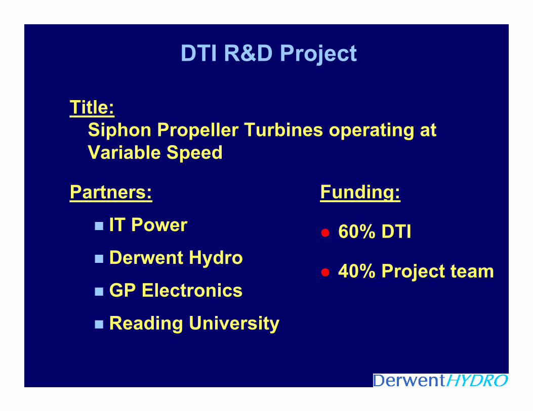
DTI R&D Project
Title:Siphon Propeller Turbines operating at Variable Speed
Partners:
IT Power
Derwent Hydro
GP Electronics
Reading University
Funding:
60% DTI
40% Project team

Background : Low-Head Hydro
High head hydro is the most economic -but the least available
The UK has an abundance of low-head sites at existing mills and river structures
But few low-head projects have proceeded in recent years
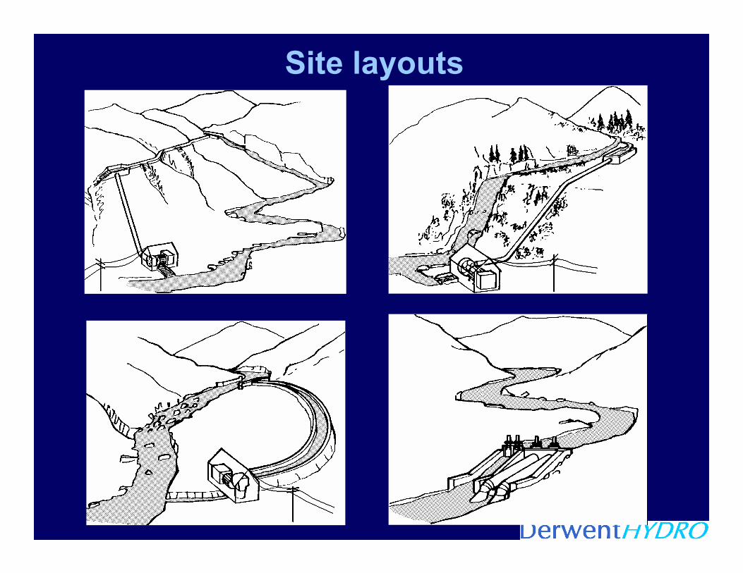
Site layouts

Historical Roots
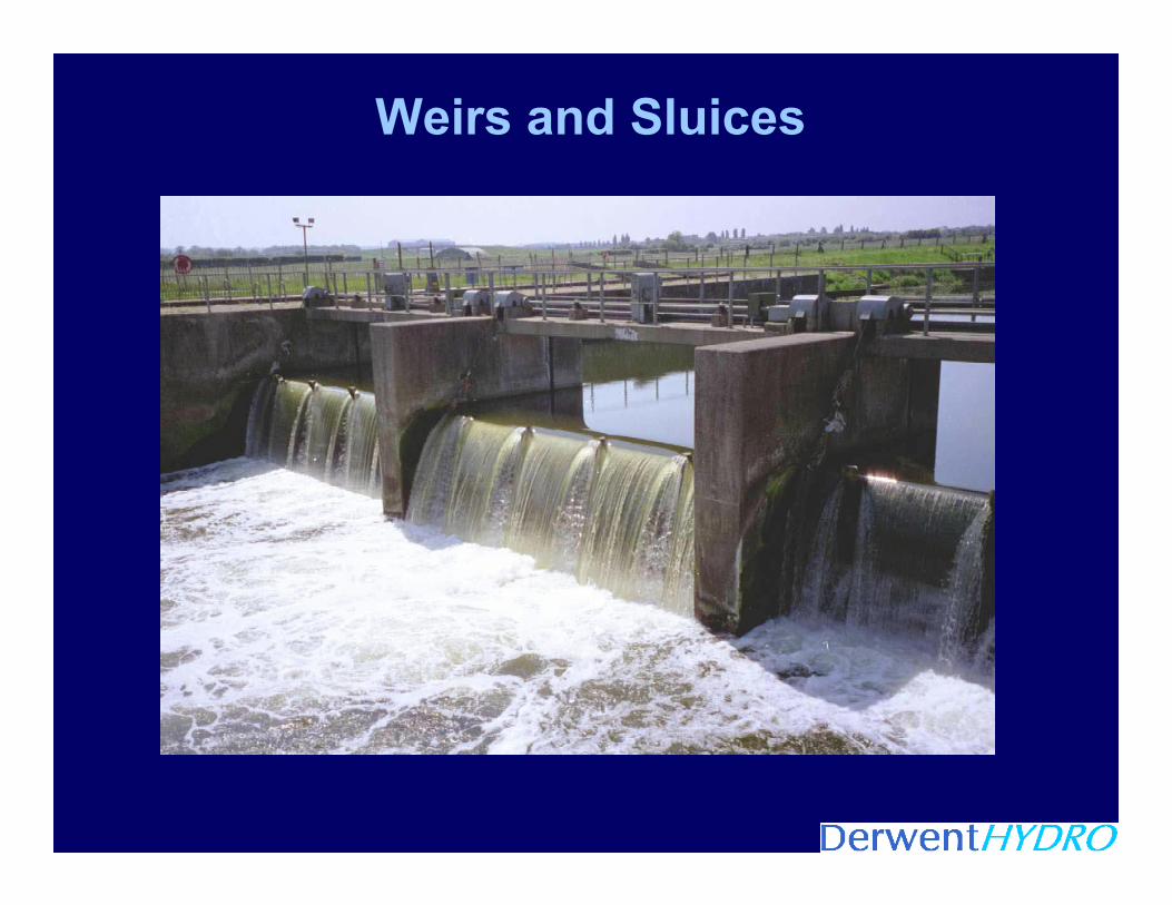
Weirs and Sluices
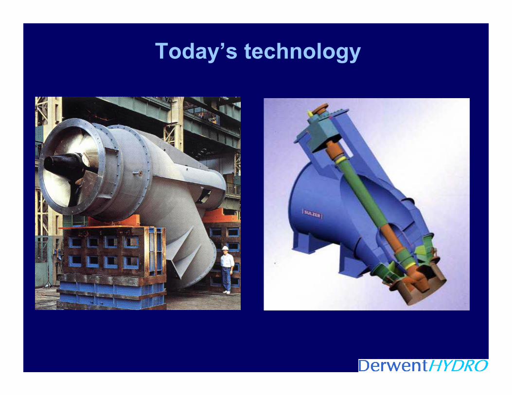
Today’s technology

Turbine configurations as head reduces
HEAD
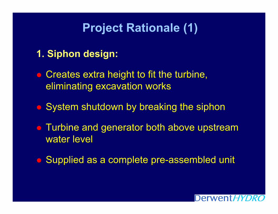
Project Rationale (1)
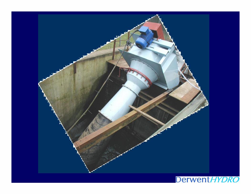
1. Siphon design:
Creates extra height to fit the turbine, eliminating excavation works
System shutdown by breaking the siphon
Turbine and generator both above upstream water level
Supplied as a complete pre-assembled unit

Project Rationale (2)
2. Variable-speed control:
For use with a simple, fixed-geometry turbine
Ensures maximum power achieved at all times
Vary speed to match changing head
Flow control without complex mechanisms
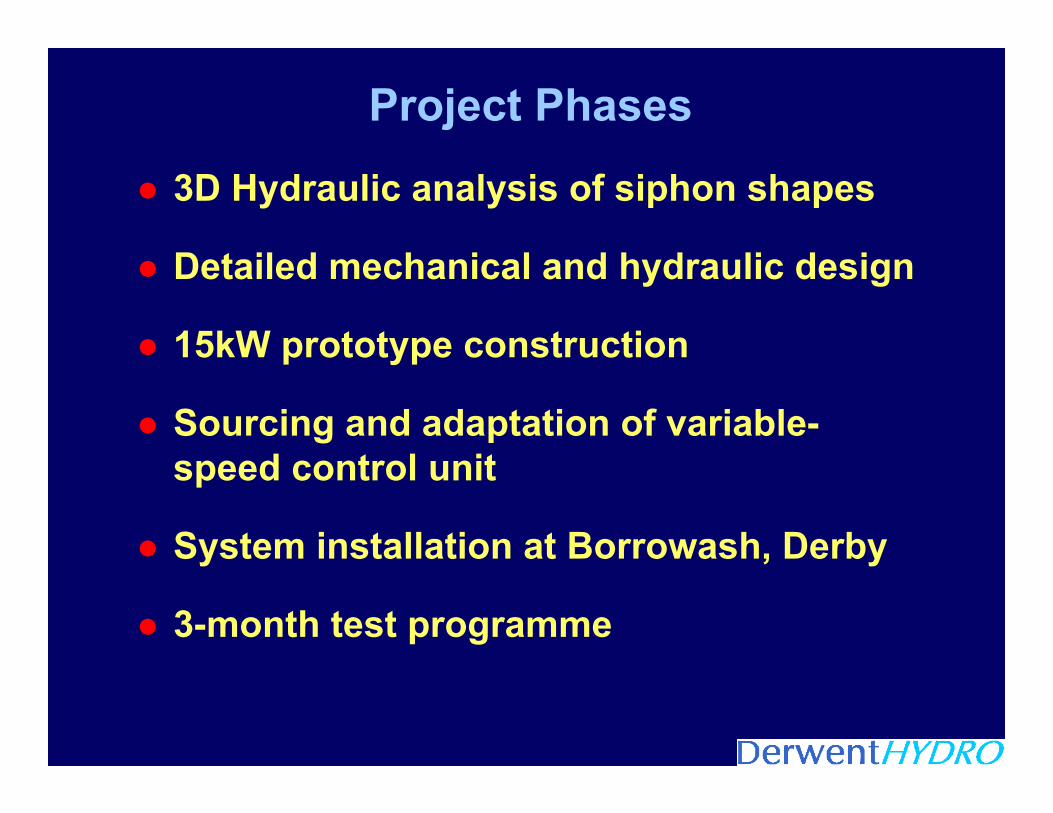
Project Phases
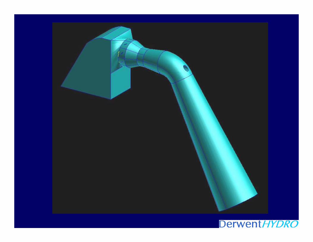
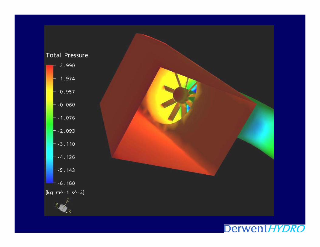
3D Hydraulic analysis of siphon shapes
Detailed mechanical and hydraulic design
15kW prototype construction
Sourcing and adaptation of variable-speed control unit
System installation at Borrowash, Derby
3-month test programme


Pow e r Ltd

Propeller runner
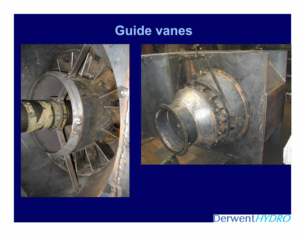
Guide vanes
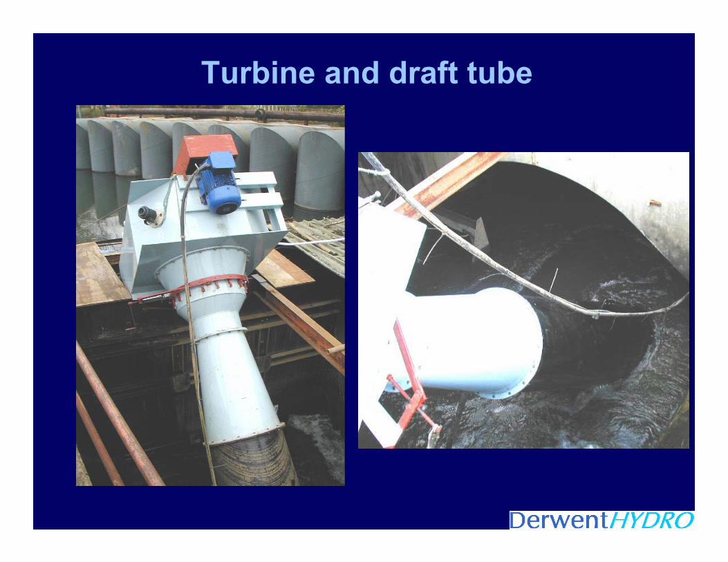
Turbine and draft tube
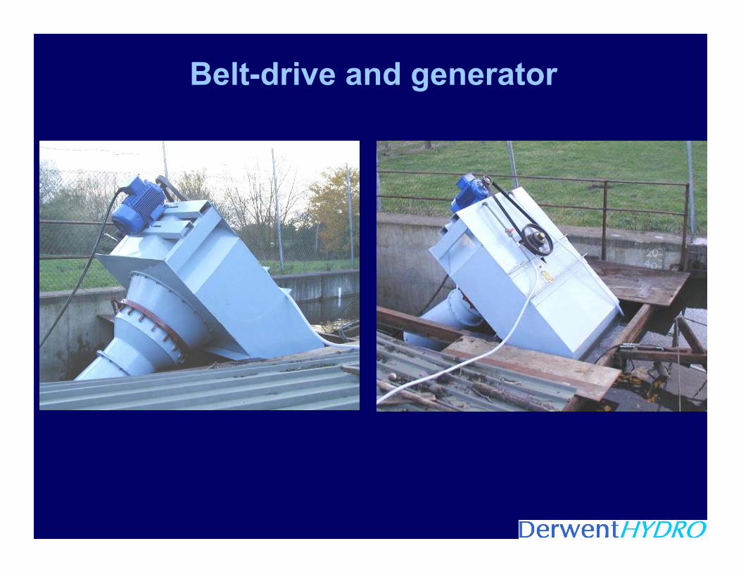
Belt-drive and generator
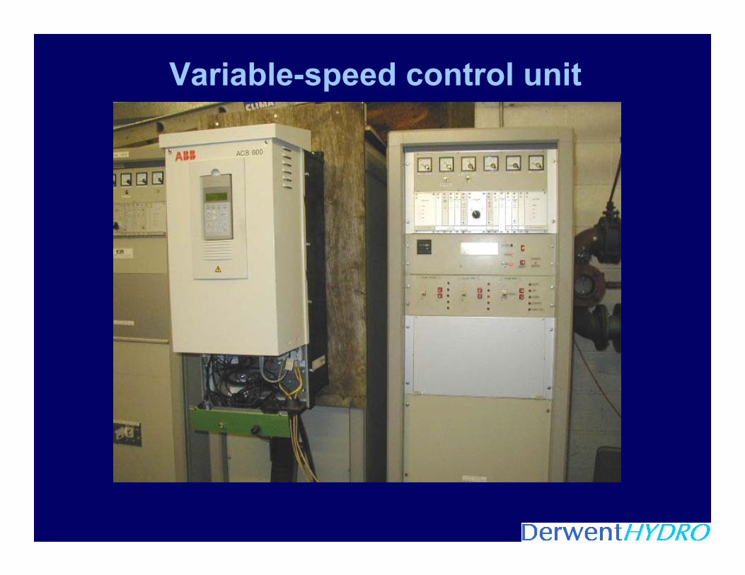
Variable-speed control unit
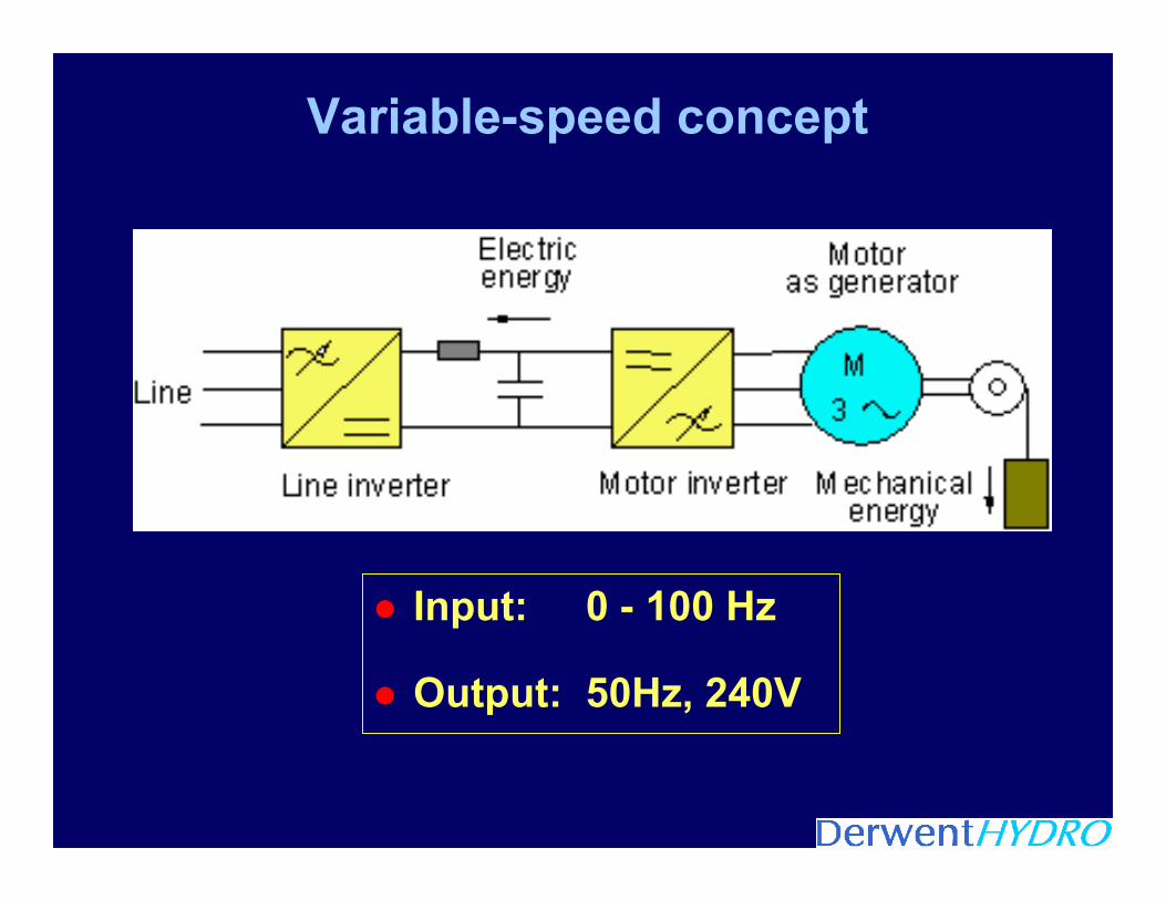
Variable-speed concept
Input: 0 - 100 Hz
Output: 50Hz, 240V

Power vs speed characteristic
0
1
2
3
4
5
6
7
8
9
10
11
12
13
14
15
0 50 100 150 200 250 300 350 400 450 500 550 600 650 700 750 800 850 900 950 1000
Runner RPM
Pow
er (k
W e
lect
ric)
0
1
2
3
4
5
6
7
8
9
10
11
12
13
14
150 165 330 495 660 825 990 1155 1320 1485 1650 1815 1980 2145 2310 2475 2640 2805 2970 3135 3300
Generator RPM
Guide vanes at 20 deg (14-01-03).
Guide vanes at 10 deg. (24-2-03)

Flow vs Speed
0.00
0.05
0.10
0.15
0.20
0.25
0.30
0.35
0.40
0.45
0.50
0.55
0.60
100 150 200 250 300 350 400 450 500 550 600 650Normalised Speed
Norm
alis
ed F
low
Test Data
Runner Data
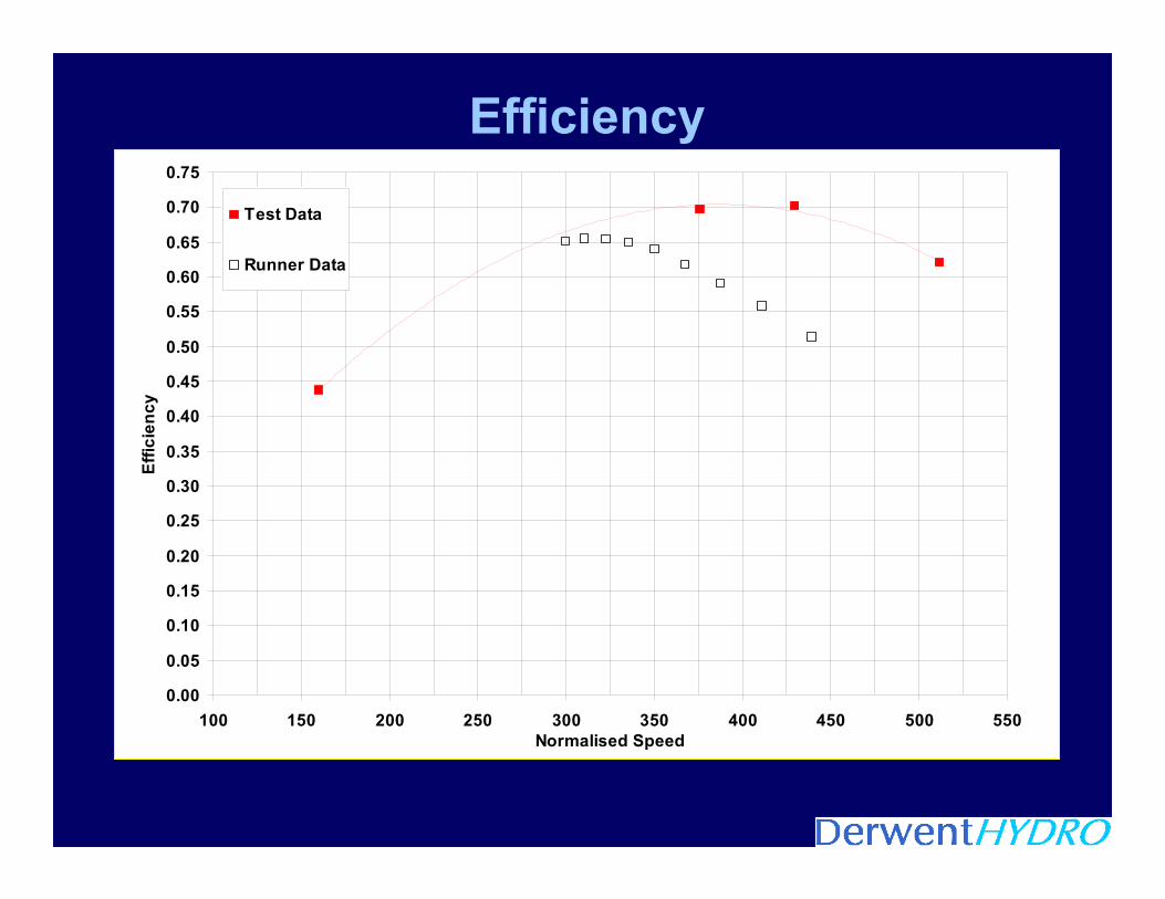
Efficiency
0.00
0.05
0.10
0.15
0.20
0.25
0.30
0.35
0.40
0.45
0.50
0.55
0.60
0.65
0.70
0.75
100 150 200 250 300 350 400 450 500 550Normalised Speed
Effic
ienc
y
Test Data
Runner Data
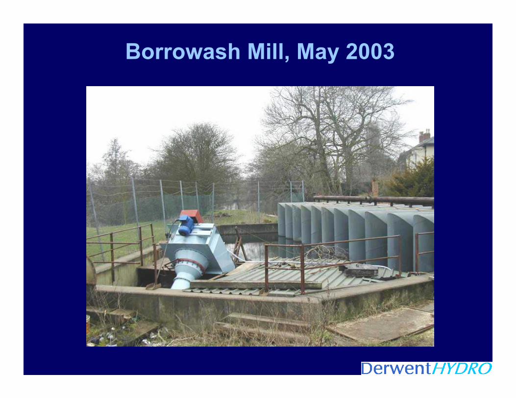
Borrowash Mill, May 2003

THE END