technical leaflet - plc control, guillevin industrial …€¦ · · 2009-09-23technical leaflet...
TRANSCRIPT
Technical Leaflet
- 1 -
Technical Leaflet For Engineer
TeSys® T Motor Management System

Technical Leaflet
Index Index ............................................................................................................................................................. 2
Chapter 1. Brief Introduction of TeSys® T Motor Management System................................................. 3 1.1 The Offer Provides You… ............................................................................................................................3
1.2 Overview of the Functionality ......................................................................................................................3 1.2.1 Control Functions................................................................................................................................................... 3 1.2.2 Protection Functions .............................................................................................................................................. 4 1.2.3 Metering and Monitoring Functions ...................................................................................................................... 4
Chapter 2. Components and Selection Guide ........................................................................................... 5 2.1 Architecture of the Offer ...............................................................................................................................5
2.2 Description of the main parts .......................................................................................................................5 2.2.1 LTM R Controller with Modbus Communication Port.......................................................................................... 6 2.2.2 LTM R Controller with Other Communication Ports ............................................................................................ 6 2.2.3 LTM E Expansion Module..................................................................................................................................... 7 2.4.4 Magelis HMI Device.............................................................................................................................................. 7
2.3 References ......................................................................................................................................................8
2.4 Selection Guide ..............................................................................................................................................9
2.5 Technical Specification ...............................................................................................................................10
2.6 Dimensions and Mechanical Installation...................................................................................................12
Chapter 3. Functionality .......................................................................................................................... 13 3.1 Measurements and Motor Protection Functions ......................................................................................13
3.2 Monitoring Functions..................................................................................................................................14 3.2.1 Statistics ............................................................................................................................................................... 14 3.2.2 Diagnostic Faults ................................................................................................................................................. 14 3.2.3 Motor States......................................................................................................................................................... 14 3.2.4 User Map.............................................................................................................................................................. 14
3.3 Motor Control Functions ............................................................................................................................15 3.3.1 Control Modes and Operating States ................................................................................................................... 15 3.3.2 Operating Modes.................................................................................................................................................. 15 3.3.3 Fault Management ............................................................................................................................................... 15
3.4 Commissioning.............................................................................................................................................15
Chapter 4. Application Examples ............................................................................................................ 16 4.1 Supported Application Segments...............................................................................................................16
4.2 Application Examples .................................................................................................................................17 4.2.1 Overload Mode Wiring Diagrams........................................................................................................................ 17 4.2.2 Independent Mode Wiring Diagrams................................................................................................................... 18 4.2.3 Reversing Mode Wiring Diagrams ...................................................................................................................... 18 4.2.4 Two-Step Wye-Delta Mode Wiring Diagrams .................................................................................................... 19 4.2.5 Two-Step Primary Resistor Mode Wiring Diagrams........................................................................................... 19 4.2.6 Two-Step Autotransformer Mode Wiring Diagrams ........................................................................................... 20 4.2.7 Two-Speed Dahlander Mode Wiring Diagrams................................................................................................... 20 4.2.8 Two-Speed Pole Changing Mode Wiring Diagrams............................................................................................ 21
- 2 -

Technical Leaflet
Chapter 1. Brief Introduction of TeSys® T Motor Management System
1.1 The Offer Provides You… TeSys® T Motor Management System offers increased protection, control, and monitoring capabilities for single-phase and 3-phase induction motors.
The system is flexible and modular which can be configured to meet the need of applications in industry as well as the needs for integrated protections systems with open communications and global architecture.
More accurate sensors and solid-state full motor protection ensures better utilization of the motor. Complete monitoring functions enable analysis of motor operating conditions and faster reaction to prevent system downtime.
The system offers diagnostic and statistics functions and configurable warnings and faults, allowing better prediction of component maintenance, and provides data to continuous improvement of the entire system.
1.2 Overview of the Functionality This section describes the controller with and without the optional expansion module for metering and monitoring, protection, and control functions.
User
Metering & MonitoringFunctions
Current Measurement
Voltage Measurement
Power Measurement
Statistics
DiagnosticsMotor States
Fault DiagnosticsWiring/Configuration Errors
Internal Fault Monitoring
Sensor Fault MonitoringThermal Overload/Current Monitoring
Voltage/Power MonitoringCommunication Monitoring
Communicationwith PLC/DCS
ModbusProfibus
CANOpen
EtherNetDeviceNet
Commissioning/Control/Monitor
ThroughPC withPowerSuiteTM
Software
Magelis HMI1 to 1
Magelis HMI1 to n
ControlFunctions
Pre-definedOperating
Modes MotorControl Modes
FaultManagement
ProtectionFunctions
ThermalOverload
ProtectionsCurrent
Protections
VoltageProtections
PowerProtectionsTeSys
CustomLogic
User Map
PLC/DCS
1.2.1 Control Functions
Functions Controller With Expansion Module Local terminal strip X X Local HMI X X Motor control modes Network X X Overload X X Independent X X Reverser X X Two-step X X
Predefined mode
Two-speed X X Ope
ratin
g m
ode
Custom Logic User defined logic for operating mode X X Manual reset X X Automatic reset X X Fault Management Remote reset X X
- 3 -

Technical Leaflet
Protection Functions Functions Controller With Expansion Module
Thermal overload X X Thermal based Motor temperature sensor X X Current phase imbalance X X Current phase loss X X Current phase reversal X X Long start (locked rotor during start) X X Jam (locked rotor during run) X X Undercurrent X X Overcurrent X X Ground current X X
Current based
Rapid cycle lockout X X Voltage phase imbalance - X Voltage phase loss - X Voltage phase reversal - X Undervoltage - X Overvoltage - X
Voltage based
Voltage load shedding - X Underpower - X Overpower - X Under power factor - X Power based
Over power factor - X
1.2.2 Metering and Monitoring Functions Metering Functions Fault Monitoring Functions
Function Controller With Expansion Function Controller With
Expansion Line currents X X Run Command Check X X Ground current X X Stop Command Check X X Average current X X Run Check Back X X Current phase imbalance X X
Diagnostic
Stop Check Back X X Thermal capacity level X X PTC connection X X Motor temperature sensor X X CT Reversal X X Frequency - X Voltage Phase Reversal - X Line to line voltage - X Current Phase Reversal X X Line voltage imbalance - X Voltage Phase Loss - X Active power - X
Wiri
ng &
co
nfig
ura-
tion
erro
rs
Phase Configuration X X Reactive power - X Stack Overflow X X Power factor - X Watchdog X X Active power consumption - X ROM Checksum X X
Mea
sure
men
t
Reactive power consumption - X EEROM X X Protection fault counts X X CPU X X Protection warning counts X X
Inte
rnal
Internal Temperature X X Diagnostic fault counts X X PTC Binary X X Motor control function counts X X PTC Analog X X St
atis
tics
Fault history X X Sensor
NTC Analog X X Internal watchdog faults X X Definite Time X X Controller internal temperature X X
Thermal Overload Inverse Thermal X X
Temperature sensor connections X X Long Start X X Current connections X X Jam X X Voltage connections - X Current Phase Imbalance X X
Current Phase Loss X X Control commands (start, stop, run check back and stop check back) X X Overcurrent X X Control configuration checksum X X Undercurrent X X
Dia
gnos
tics
Communication loss X X Internal Ground Current X X
Cur
rent
External Ground Current X X Motor Control States motor start/LO1 starts/LO2 starts X X Overvoltage - X Operating time X X Undervoltage - X Motor starts per hour X X
Voltage Voltage Phase Imbalance - X
Last start max current X X Underpower - X Last start time X X Overpower - X Time to trip X X Under Power Factor - X M
otor
Sta
tes
Time to reset X X
Power
Over Power Factor - X PLC to LTM R X X
Comms Loss LTM E to LTM R - X
- 4 -
Technical Leaflet
Chapter 2. Components and Selection Guide
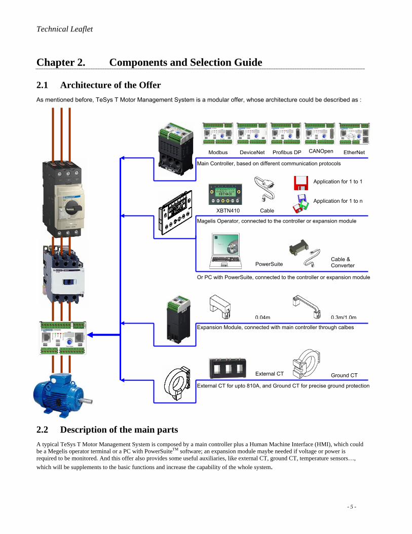
2.1 Architecture of the Offer As mentioned before, TeSys T Motor Management System is a modular offer, whose architecture could be described as :
DeviceNet Profibus DP CANOpen
Main Controller, based on different communication protocols
Expansion Module, connected with main controller through calbes
0.04m 0.3m/1.0m
External CT Ground CT
Magelis Operator, connected to the controller or expansion module
XBTN410
PowerSuite Cable & Converter
Or PC with PowerSuite, connected to the controller or expansion module
External CT for upto 810A, and Ground CT for precise ground protection
Modbus
Cable
Application for 1 to 1
Application for 1 to n
EtherNet
2.2 Description of the main parts A typical TeSys T Motor Management System is composed by a main controller plus a Human Machine Interface (HMI), which could be a Megelis operator terminal or a PC with PowerSuiteTM software; an expansion module maybe needed if voltage or power is required to be monitored. And this offer also provides some useful auxiliaries, like external CT, ground CT, temperature sensors…, which will be supplements to the basic functions and increase the capability of the whole system.
- 5 -
Technical Leaflet
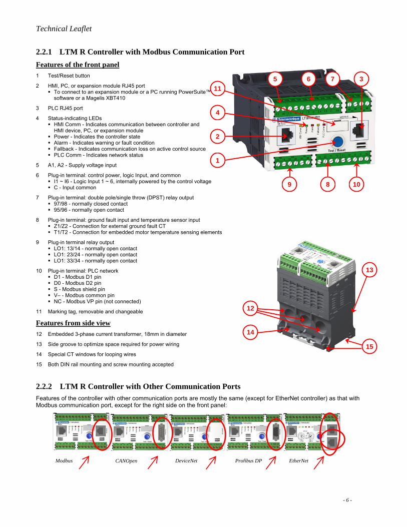
2.2.1 LTM R Controller with Modbus Communication PortFeatures of the front panel 1 Test/Reset button
2 HMI, PC, or expansion module RJ45 port To connect to an expansion module or a PC running PowerSuite™
software or a Magelis XBT410
3 PLC RJ45 port
4 Status-indicating LEDs HMI Comm - Indicates communication between controller and
HMI device, PC, or expansion module Power - Indicates the controller state Alarm - Indicates warning or fault condition Fallback - Indicates communication loss on active control source PLC Comm - Indicates network status
5 A1, A2 - Supply voltage input
6 Plug-in terminal: control power, logic Input, and common I1 ~ I6 - Logic Input 1 ~ 6, internally powered by the control voltage
1
2
3
4
6 7
9 8 10
511
C - Input common
7 Plug-in terminal: double pole/single throw (DPST) relay output 97/98 - normally closed contact 95/96 - normally open contact
8 Plug-in terminal: ground fault input and temperature sensor input Z1/Z2 - Connection for external ground fault CT T1/T2 - Connection for embedded motor temperature sensing elements
9 Plug-in terminal relay output LO1: 13/14 - normally open contact LO1: 23/24 - normally open contact LO1: 33/34 - normally open contact
12
13
14
15
10 Plug-in terminal: PLC network D1 - Modbus D1 pin D0 - Modbus D2 pin S - Modbus shield pin V– - Modbus common pin NC - Modbus VP pin (not connected)
11 Marking tag, removable and changeable
Features from side view 12 Embedded 3-phase current transformer, 18mm in diameter
13 Side groove to optimize space required for power wiring
14 Special CT windows for looping wires
15 Both DIN rail mounting and screw mounting accepted
2.2.2 LTM R Controller with Other Communication Ports Features of the controller with other communication ports are mostly the same (except for EtherNet controller) as that with Modbus communication port, except for the right side on the front panel:
Modbus CANOpen DeviceNet Profibus DP EtherNet
- 6 -
Technical Leaflet
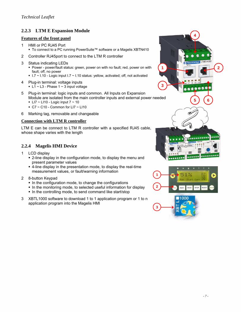
2.2.3 LTM E Expansion Module Features of the front panel 1 HMI or PC RJ45 Port
To connect to a PC running PowerSuite™ software or a Magelis XBTN410
2 Controller RJ45port to connect to the LTM R controller
3 Status indicating LEDs Power - power/fault status: green, power on with no fault; red, power on with fault; off, no power
I.7 ~ I.10 - Logic input I.7 ~ I.10 status: yellow, activated; off, not activated
4 Plug-in terminal: voltage inputs L1 ~ L3 - Phase 1 ~ 3 input voltage
5 Plug-in terminal: logic inputs and common. All Inputs on Expansion Module are isolated from the main controller inputs and external power needed
1 2
3
4
LI7 ~ LI10 - Logic input 7 ~ 10 C7 ~ C10 - Common for LI7 ~ LI10
6 Marking tag, removable and changeable
Connection with LTM R controller LTM E can be connect to LTM R controller with a specified RJ45 cable, whose shape varies with the length
2.2.4 Magelis HMI Device 1 LCD display
2-line display in the configuration mode, to display the menu and present parameter values
4-line display in the presentation mode, to display the real-time measurement values, or fault/warning information
2 8-button Keypad In the configuration mode, to change the configurations In the monitoring mode, to selected useful information for display In the controlling mode, to send command like start/stop
3 XBTL1000 software to download 1 to 1 application program or 1 to n application program into the Magelis HMI
5 6
Network
1
2
3
- 7 -

Technical Leaflet
2.3 References Picture Description Category Branches Part Number
FLA Range (A) Control Voltage (V) DC 24 LTM R08MBD 0.4 ~ 8 AC 100 ~ 240 LTM R08MFM DC 24 LTM R27MBD 1.35 ~ 27 AC 100 ~ 240 LTM R27MFM DC 24 LTM R100MBD
Modbus Protocol
5 ~ 100 AC 100 ~ 240 LTM R100MFM DC 24 LTM R08PBD 0.4 ~ 8 AC 100 ~ 240 LTM R08PFM DC 24 LTM R27PBD 1.35 ~ 27 AC 100 ~ 240 LTM R27PFM DC 24 LTM R100PBD
Profibus DP
5 ~ 100 AC 100 ~ 240 LTM R100PFM DC 24 LTM R08DBD 0.4 ~ 8 AC 100 ~ 240 LTM R08DFM DC 24 LTM R27DBD 1.35 ~ 27 AC 100 ~ 240 LTM R27DFM DC 24 LTM R100DBD
DeviceNet
5 ~ 100 AC 100 ~ 240 LTM R100DFM DC 24 LTM R08CBD 0.4 ~ 8 AC 100 ~ 240 LTM R08CFM DC 24 LTM R27CBD 1.35 ~ 27 AC 100 ~ 240 LTM R27CFM DC 24 LTM R100CBD
Main contoller
CANOpen
5 ~ 100 AC 100 ~ 240 LTM R100CFM Inputs Control Voltage (V) Part Number
DC 24 LTM EV40BD
Expansion module
AC 100 ~ 240 LTM EV40FM
Magelis HMI, require 1 to 1 or 1 to n application programs XBTN410
PC with PowerSuiteTM software (LTMCONF)
Ratio 30:1 LUTC0301 50:1 LUTC0501 100:1 LUTC1001 200:1 LUTC2001 400:1 LUTC4001
TeSys® U CT
800:1 LUTC8001 100:1 LT6CT1001 400:1 LT6CT4001 LT6 CT 800:1 LT6CT8001 300:5 31102-085 600:5 31105-049-50
External CT, support current sensing up to 810A
Square D Starter Size CT 900:5 31124-033
Diameter (mm) 30 TA30 50 PA50 80 IA80 120 MA120
Ground CT, support ground current detection
TeSys® U CT
196 SA200 Length (m)
TeSys® T 0.04 LTMCC004
0.3 LU9R03
Connection cable from the expansion module to main controller TeSys® U
1.0 LU9R10
Connection cable to Magelis HMI Magelis 2.5 XBTZ938
0.3 VW3A8306R03 1.0 VW3A8306R10
Connection cable to Modbus network PowerSuite™
3.0 VW3A8306R30
- 8 -

Technical Leaflet
2.4 Selection Guide Requirements of the functionality, or specifications of the system to be designed are most important factors during the selection phases. One can follow the below procedure to make a selection:
Start
Need a MultifunctionController?
Need Communicationwith PLC?
Which Kind ofFieldbus?
Need VoltageProtection/Monitoring?
Need HMI?
Need GroundFault Protection?
Internal or External?
Need MotorTemperature Sensor?
Select FLA Range andControl Voltage baseon the requirement
Select GroundFault C.T.
based on therequirement
Select temperaturesensors based onthe requirement
Select Expansion Moduleaccording to the Input
Control Voltage, and theconnection cable
Select therelevant
communication cable
Current > 100? Select External C.T.based on the current
Need PC monitoring?
End
Y Y
Modbus
Select LTM R forProfibus DP
Select LTM R forCANOpen
Select LTM R forDeviceNet
Select LTM R forEtherNet
N
Y
N
Y
N
N
N
N
N
Select XBTN410 andthe cable XBTZ938
Select PowerSuiteTM
Software and thecable VW3A8106
Y
Y
YExternal
Y
N
N
EtherNet
DeviceNet
CANOpen
ProfibusDP
! IMPORTANT MESSAGE !It is necessary to finish the commissioningprocess before normal use. At least one of thebelow parts should be selected for thecommissioning process:
Magelis HMI XBTN410 and the cablePowerSuite software with PC and the cableMaster network PLC controller, networkconfiguration utility and cables
YInternal
Need additional inputs? Y
1 to 1?1 to n?
Select 1 to 1application
Select 1 to napplication
1 to 1 1 to n
Important Message: While the main controller has a wide adjustable range, it is good practice to choose the unit where the motor FLA is closer to the mid range rather than at the limits of the adjustable range in order to achieve:
• Greater accuracy &Greater flexibility
- 9 -
Technical Leaflet
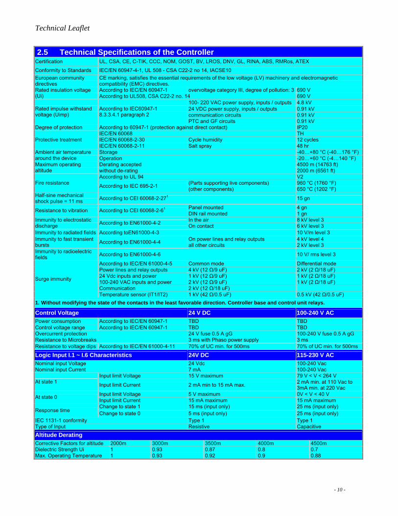
2.5 Technical Specifications of the Controller Certification UL, CSA, CE, C-TIK, CCC, NOM, GOST, BV, LROS, DNV, GL, RINA, ABS, RMRos, ATEX
Conformity to Standards IEC/EN 60947-4-1, UL 508 - CSA C22-2 no 14, IACSE10 European community directives
CE marking, satisfies the essential requirements of the low voltage (LV) machinery and electromagnetic compatibility (EMC) directives. According to IEC/EN 60947-1 overvoltage category III, degree of pollution: 3 690 V Rated insulation voltage
(Ui) According to UL508, CSA C22-2 no. 14 690 V 100- 220 VAC power supply, inputs / outputs 4.8 kV 24 VDC power supply, inputs / outputs 0.91 kV communication circuits 0.91 kV
Rated impulse withstand voltage (Uimp)
According to IEC60947-1 8.3.3.4.1 paragraph 2
PTC and GF circuits 0.91 kV Degree of protection According to 60947-1 (protection against direct contact) IP20
IEC/EN 60068 TH IEC/EN 60068-2-30 Cycle humidity 12 cycles Protective treatment IEC/EN 60068-2-11 Salt spray 48 hr Storage -40…+80 °C (-40…176 °F) Ambient air temperature
around the device Operation -20…+60 °C (-4…140 °F) Derating accepted 4500 m (14763 ft) Maximum operating
altitude without de-rating 2000 m (6561 ft) According to UL 94 V2
(Parts supporting live components) 960 °C (1760 °F) Fire resistance According to IEC 695-2-1 (other components) 650 °C (1202 °F) Half-sine mechanical shock pulse = 11 ms According to CEI 60068-2-271 15 gn
Panel mounted 4 gn Resistance to vibration According to CEI 60068-2-61
DIN rail mounted 1 gn In the air 8 kV level 3 Immunity to electrostatic
discharge According to EN61000-4-2 On contact 6 kV level 3 Immunity to radiated fields According toEN61000-4-3 10 V/m level 3
On power lines and relay outputs 4 kV level 4 Immunity to fast transient bursts According to EN61000-4-4 all other circuits 2 kV level 3 Immunity to radioelectric fields According to EN61000-4-6 10 V/ rms level 3
According to IEC/EN 61000-4-5 Common mode Differential mode Power lines and relay outputs 4 kV (12 Ω/9 uF) 2 kV (2 Ω/18 uF) 24 Vdc inputs and power 1 kV (12 Ω/9 uF) 1 kV (2 Ω/18 uF) 100-240 VAC inputs and power 2 kV (12 Ω/9 uF) 1 kV (2 Ω/18 uF) Communication 2 kV (12 Ω/18 uF)
Surge immunity
Temperature sensor (IT1/IT2) 1 kV (42 Ω/0.5 uF) 0.5 kV (42 Ω/0.5 uF) 1. Without modifying the state of the contacts in the least favorable direction. Controller base and control unit relays.
Control Voltage 24 V DC 100-240 V AC Power consumption According to IEC/EN 60947-1 TBD TBD Control voltage range According to IEC/EN 60947-1 TBD TBD Overcurrent protection 24 V fuse 0.5 A gG 100-240 V fuse 0.5 A gG Resistance to Microbreaks 3 ms with Phaso power supply 3 ms Resistance to voltage dips According to IEC/EN 61000-4-11 70% of UC min. for 500ms 70% of UC min. for 500ms
Logic Input I.1 ~ I.6 Characteristics 24V DC 115-230 V AC Nominal input Voltage 24 Vdc 100-240 Vac Nominal input Current 7 mA 100-240 Vac
Input limit Voltage 15 V maximum 79 V < V < 264 V At state 1 Input limit Current 2 mA min to 15 mA max. 2 mA min. at 110 Vac to
3mA min. at 220 Vac Input limit Voltage 5 V maximum 0V < V < 40 V At state 0 Input limit Current 15 mA maximum 15 mA maximum Change to state 1 15 ms (input only) 25 ms (input only)
Response time Change to state 0 5 ms (input only) 25 ms (input only) IEC 1131-1 conformity Type 1 Type 1 Type of Input Resistive Capacitive Altitude Derating Corrective Factors for altitude 2000m 3000m 3500m 4000m 4500m Dielectric Strength Ui 1 0.93 0.87 0.8 0.7 Max. Operating Temperature 1 0.93 0.92 0.9 0.88
- 10 -
Technical Leaflet
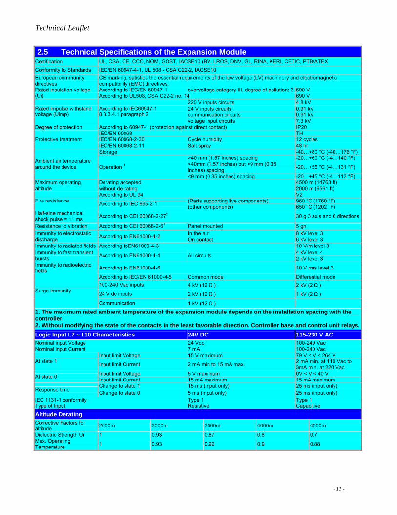
2.5 Technical Specifications of the Expansion Module Certification UL, CSA, CE, CCC, NOM, GOST, IACSE10 (BV, LROS, DNV, GL, RINA, KERI, CETIC, PTB/ATEX
Conformity to Standards IEC/EN 60947-4-1, UL 508 - CSA C22-2, IACSE10 European community directives
CE marking, satisfies the essential requirements of the low voltage (LV) machinery and electromagnetic compatibility (EMC) directives. According to IEC/EN 60947-1 overvoltage category III, degree of pollution: 3 690 V Rated insulation voltage
(Ui) According to UL508, CSA C22-2 no. 14 690 V 220 V inputs circuits 4.8 kV 24 V inputs circuits 0.91 kV communication circuits 0.91 kV
Rated impulse withstand voltage (Uimp)
According to IEC60947-1 8.3.3.4.1 paragraph 2
voltage input circuits 7.3 kV Degree of protection According to 60947-1 (protection against direct contact) IP20
IEC/EN 60068 TH IEC/EN 60068-2-30 Cycle humidity 12 cycles Protective treatment IEC/EN 60068-2-11 Salt spray 48 hr Storage -40…+80 °C (-40…176 °F)
>40 mm (1.57 inches) spacing -20…+60 °C (-4…140 °F) <40mm (1.57 inches) but >9 mm (0.35 inches) spacing -20…+55 °C (-4…131 °F)
Ambient air temperature around the device Operation 1
<9 mm (0.35 inches) spacing -20…+45 °C (-4…113 °F) Derating accepted 4500 m (14763 ft) Maximum operating
altitude without de-rating 2000 m (6561 ft) According to UL 94 V2
(Parts supporting live components) 960 °C (1760 °F) Fire resistance According to IEC 695-2-1 (other components) 650 °C (1202 °F) Half-sine mechanical shock pulse = 11 ms According to CEI 60068-2-272 30 g 3 axis and 6 directions
Resistance to vibration According to CEI 60068-2-61 Panel mounted 5 gn In the air 8 kV level 3 Immunity to electrostatic
discharge According to EN61000-4-2 On contact 6 kV level 3 Immunity to radiated fields According toEN61000-4-3 10 V/m level 3
4 kV level 4 Immunity to fast transient bursts According to EN61000-4-4 All circuits 2 kV level 3 Immunity to radioelectric fields According to EN61000-4-6 10 V rms level 3
According to IEC/EN 61000-4-5 Common mode Differential mode 100-240 Vac inputs 4 kV (12 Ω ) 2 kV (2 Ω )
24 V dc inputs 2 kV (12 Ω ) 1 kV (2 Ω ) Surge immunity
Communication 1 kV (12 Ω )
1. The maximum rated ambient temperature of the expansion module depends on the installation spacing with the controller. 2. Without modifying the state of the contacts in the least favorable direction. Controller base and control unit relays.Logic Input I.7 ~ I.10 Characteristics 24V DC 115-230 V AC Nominal input Voltage 24 Vdc 100-240 Vac Nominal input Current 7 mA 100-240 Vac
Input limit Voltage 15 V maximum 79 V < V < 264 V At state 1 Input limit Current 2 mA min to 15 mA max. 2 mA min. at 110 Vac to
3mA min. at 220 Vac Input limit Voltage 5 V maximum 0V < V < 40 V At state 0 Input limit Current 15 mA maximum 15 mA maximum Change to state 1 15 ms (input only) 25 ms (input only)
Response time Change to state 0 5 ms (input only) 25 ms (input only) IEC 1131-1 conformity Type 1 Type 1 Type of Input Resistive Capacitive Altitude Derating Corrective Factors for altitude 2000m 3000m 3500m 4000m 4500m
Dielectric Strength Ui 1 0.93 0.87 0.8 0.7 Max. Operating Temperature 1 0.93 0.92 0.9 0.88
- 11 -

Technical Leaflet
2.6 Dimensions and Mechanical Installation Dimensions of the Controller and Expansion Module
Minimum Clearance Zone:
Mounting on A Solid Mounting Plate or on A TE Plate
- 12 -
Technical Leaflet
Chapter 3. Functionality
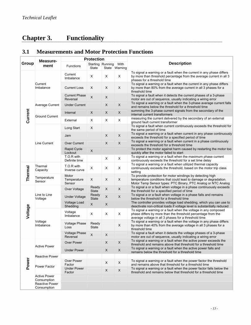
3.1 Measurements and Motor Protection Functions Protection
Group Measure-ment Functions Starting
State Running
State With
WarningDescription
Current Imbalance X X X
To signal a warning or a fault when the current in any phase differs by more than threshold percentage from the average current in all 3 phases for a threshold time
Current Loss X X X To signal a warning or a fault when the current in any phase differs by more than 80% from the average current in all 3 phases for a threshold time
Current Imbalance
Current Phase Reversal X X To signal a fault when it detects the current phases of a 3-phase
motor are out of sequence, usually indicating a wiring error
Average Current Under Current X X To signal a warning or a fault when the 3-phase average current falls and remains below the threshold for a threshold time
Internal X X X summing the 3-phase current signals from the secondary of the internal current transformers Ground Current
External X X X measuring the current delivered by the secondary of an external ground fault current transformer
Long Start X To signal a fault when current continuously exceeds the threshold for the same period of time
Jam X X To signal a warning or a fault when current in any phase continuously exceeds the threshold for a specified period of time
Over Current X X To signal a warning or a fault when current in a phase continuously exceeds the threshold for a threshold time
Rapid Cycle Lockout X To protect the motor against harm caused by restarting the motor too
quickly after the motor failed to start
Cur
rent
Line Current
T.O.R with Definite time X X To signal a warning or a fault when the maximum phase current
continuously exceeds the threshold for a set time delay
Thermal Capacity
T.O.R with Inverse curve X X X
To signal a warning or a fault when utilized thermal capacity continuously exceeds the threshold, based on the motor trip class setting
Ther
mal
Temperature Sensor
Motor Temperature Sensor
X X X To provide protection for motor windings by detecting high temperature conditions that could lead to damage or degradation. Motor Temp Sensor types: PTC Binary, PTC Analog or NTC Analog
Over Voltage Ready State X X To signal a or a fault when voltage in a phase continuously exceeds
the threshold for a specified period of time
Under Voltage Ready State X X To signal a or a fault when voltage in a phase falls and remains
below the threshold for a threshold time Line to Line Voltage
Voltage Load Shedding X X The controller provides voltage load shedding, which you can use to
deactivate non-critical loads if voltage level is substantially reduced
Voltage Imbalance X X X
To signal a warning or a fault when the voltage in any composed phase differs by more than the threshold percentage from the average voltage in all 3 phases for a threshold time
Voltage Phase Loss
Ready State X
To signal a warning or a fault when the voltage in any phase differs by more than 40% from the average voltage in all 3 phases for a threshold time
Volta
ge
Voltage Imbalance
Voltage Phase Reversal X X To signal a fault when it detects the voltage phases of a 3-phase
motor are out of sequence, usually indicating a wiring error
Over Power X X To signal a warning or a fault when the active power exceeds the threshold and remains above that threshold for a threshold time Active Power
Under Power X X To signal a warning or a fault when the active power falls and remains below the threshold for a threshold time
Reactive Power Over Power Factor X X To signal a warning or a fault when the power factor the threshold
and remains above that threshold for a threshold time Power Factor Under Power Factor X X To signal a warning or a fault when the power factor falls below the
threshold and remains below that threshold for a threshold time Active Power Consumption
Pow
er
Reactive Power Consumption
- 13 -

Technical Leaflet
3.2 Monitoring Functions
3.2.1 Statistics Protection Faults and Warning Counts
The controller records the total number of faults detected for the all the motor protection functions.
Diagnostic Faults Counts
The controller records the total number of faults detected for all the diagnostic functions.
Motor Control Counts
The controller records the total number of motor control counts.
Fault History
The controller stores details of the last 5 faults detected. Fault N0 is the last fault recorded, fault N1 to fault N4 are the four previous consecutive faults.
3.2.2 Diagnostic Faults Internal Watchdog Faults
Major faults, in which the controller is unable to reliably execute its own programming, the communication with the controller is not possible and can only attempt to shut down the controller.And minor faults, in which the controller is unreliable and protection could be compromised. During a minor fault, the controller continues to attempt to monitor status and communications, but will not accept any start commands.
Controller Internal Temperature
The controller measures its internal temperature and records the highest value detected. The controller will indicate a warning or minor fault or major fault condition when the corresponding threshold is exceeded respectively.
Control Commands
The controller performs diagnostic functions that detect and monitor the proper functionality of control commands.
Current Transformer Connections / Voltage Connections
The controller detects incorrect or conflicting current transformer wiring and will report a fault condition.
Temperature Sensor Connections
When the LTM R Motor Management Controller is configured for motor temperature sensor protection, the controller also provides short-circuit and open-circuit detection for the temperature sensing element.
Controller Configuration Checksum
The controller verifies the software configuration to make sure it has not been accidentally modified, by performing a checksum of the EEPROM and the FLASH memories.
Communication Loss
The LTM R Motor Management Controller monitors the communication with the network port, LTM E Expansion Module, HMI device (XBTN410), and local terminal connection.
3.2.3 Motor States The controller tracks motor state statistical values memorized by controller, for operational analysis. The controller tracks and records the value detected by the motor control functions.
3.2.4 User Map In order to improve communication performance and flexibility, a special designed function User Map is provided with user map variables, which allows user to read values of non contiguous registers in a continuous way.
- 14 -
Technical Leaflet
3.3 Motor Control Functions
3.3.1 Control Modes and Operating States Control Modes The Control Mode defines the device interface that will command controller outputs. Control modes include:
Local terminal strip, controller outputs are commanded by input devices wired to the input terminals on the front face of the controller
Local HMI, controller outputs are commanded by an HMI device connected to the controller’s Local RJ45 port Network, controller outputs are commanded by a network PLC connected to the controller network port
Operating States The controller responds to the state of the motor and provides control, monitoring and protection functions appropriate to each of the motor’s operating states. A motor’s primary operating states are: Ready, Not Ready, Start and Run. Fault and Warning Conditions may occur in any of the motor states. A fault response may change the operating state from Ready to Not Ready.
3.3.2 Operating Modes The controller is provided with 5 pre-defined operating modes, each of which is designed to meet the requirements of a common application configuration. The pre-defined operating modes are:
Overload Mode Independent Mode, for FVNR and DOL starter applications Reverser Mode, for full voltage Reversing starter applications Two-step Mode, for reduced voltage applications including Wye Delta, Primary Resistor and Autotransfomer Two-Speed Mode, for two speed Pole Changer and Consequent Pole (Dahlander) type motor applications
To see the typical wiring schemes for pre-defined operating modes, please refer to Chapter 4.2, Application Examples.
Other than the pre-defined operating modes, another Custom Operation Mode is also provided, in which LTM R controller provides the customer a flexible function – custom logic with which the user can tailor one of the predefined operating modes to include user defined input and output assignments, or to introduce timers, counters, boolean logic (AND,NOT, OR) and math functions to define the desired behavior of the slave motor controller for the specific application.
3.3.3 Fault Management The setting of the Fault Reset Mode parameter determines how the controller manages faults. The Fault Reset Mode selections include:
Manual Reset Mode, every fault reset command must be performed by on-site personnel. A manual reset will block all reset commands from a remote PLC traveling over the network - even when the Network is the valid control source..
Automatic Reset Mode, permits the controller to automatically reset faults occurring at unmanned installations. Parameters allow the controller to reset the fault and prepare controller for the next intended operation.
Remote Reset Mode, to permit resetting faults from the PLC over a network. This provides centralized monitoring and control of equipment installations. The Control Mode parameter selection determines the available reset methods.
3.4 Commissioning Commissioning is a pre-process toward the system before using, which includes: initialization of the installed devices, and configuration of controller parameters required to control, protect and monitor the controller, expansion module, and other devices included in the application.
Commissioning could be implemented by 3 means: Using the keypad of the Magelis XBTN410 HMI device Using a PC running PowerSuite™ software Using the network port
- 15 -

Technical Leaflet
Chapter 4. Application Examples
4.1 Supported Application Segments Supported Machine Segments
Machine segment Examples Water Water treatment (blowers and agitators)
Cement Glass Steel Metal, Minerals and Mining
Ore-Extraction Petrochemical Oil and gas processing Refinery, Offshore Platform
Microelectronic Pharmaceutical
Cosmetics Detergents Fertilizers Chemical Industry
Paint Automotive transfer lines Transportation Industry Airports Tunnel machines
Process and special machine segments
Other industry Cranes Pumping systems Paper conversion Printing lines
Complex machine segments
Includes highly automated or coordinated machines used in: HVAC
Supported IndustriesIndustry Sectors Application
Office buildings Shopping centers Industrial buildings Ships Hospitals Cultural facilities
Building
Airports
Control and manage the building facilities: Critical HVAC systems Water Air Gas Electricity Steam
Metal, mineral, and mining: cement, glass, steel, ore-extraction Microelectronic Petrochemical Chemical: pulp and paper industry Pharmaceutical
Industry
Food and beverage
Control and monitor pump motors Ventilation Control load traction and movements View status and communicate with
machines Process and communicate the data
captured Remote data management for one or
several sites via Internet Water treatment and transportation Transportation infrastructure for people and freight: airports, road tunnels, subways and tramways
Energy and Infrastructure
Power generation and transport
Control and monitor pump motors Ventilation Remote control of wind turbine Remote data management for one or
several sites via the internet
- 16 -

Technical Leaflet
4.2 Application Examples
4.2.1 Overload Mode Wiring Diagrams Monitoring of the motor load where control (start/stop) of the motor load is achieved by a mechanism other than the controller.
Diagram with 3-Wire Local Control Diagram with 2-Wire Local Control
Diagram with 3-Wire Local Control with Network Control Selectable Diagram with 2-Wire Local Control with Network Control Selectable
- 17 -

Technical Leaflet
4.2.2 Independent Mode Wiring Diagrams Direct-on-line (across-the-line), full-voltage, non-reversing motor starting applications.
Diagram with 3-Wire Local Control
Diagram with 2-Wire Local Control
Diagram with 3-Wire Local Control with Network control selectable
Diagram with 2-Wire Local Control with Network control selectable
Diagram with 2-Wire Local Control
Diagram with 3-Wire Local Control with Network Control Selectable
Diagram with 2-Wire Local Control with Network Control Selectable Diagram with 3-Wire Local Control
4.2.3 Reversing Mode Wiring Diagrams Direct-on-line (across-the-line), full-voltage, reversing motor starting applications.
- 18 -

Technical Leaflet
4.2.4 Two-Step Wye-Delta Mode Wiring Diagrams Reduced voltage starting motor applications using Wye-Delta wiring.
Diagram with 2-Wire Local Control
Diagram with 3-Wire Local Control with Network Control Selectable
Diagram with 2-Wire Local Control with Network Control Selectable Diagram with 3-Wire Local Control
4.2.5 Two-Step Primary Resistor Mode Wiring Diagrams Reduced voltage starting motor applications using Primary Resistor.
Diagram with 2-Wire Local Control with Network Control Selectable Diagram with 3-Wire Local Control
Diagram with 2-Wire Local Control
Diagram with 3-Wire Local Control with Network Control Selectable
- 19 -
Technical Leaflet
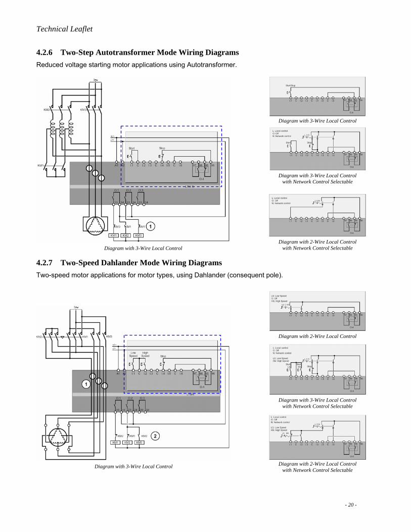
4.2.6 Two-Step Autotransformer Mode Wiring Diagrams Reduced voltage starting motor applications using Autotransformer.
Diagram with 3-Wire Local Control
Diagram with 3-Wire Local Control
Diagram with 3-Wire Local Control with Network Control Selectable
Diagram with 2-Wire Local Control with Network Control Selectable
4.2.7 Two-Speed Dahlander Mode Wiring Diagrams Two-speed motor applications for motor types, using Dahlander (consequent pole).
Diagram with 2-Wire Local Control
Diagram with 3-Wire Local Control with Network Control Selectable
Diagram with 2-Wire Local Control with Network Control Selectable
Diagram with 3-Wire Local Control
- 20 -

Technical Leaflet
4.2.8 Two-Speed Pole Changing Mode Wiring Diagrams Two-speed motor applications for motor types, using Pole Changer.
Diagram with 2-Wire Local Control
Diagram with 3-Wire Local Control with Network Control Selectable
Diagram with 2-Wire Local Control with Network Control Selectable Diagram with 3-Wire Local Control
- 21 -