technical manual for sunrise rc, tw, ts, tc, bc
TRANSCRIPT

Technical Manual for
SUNRISE RC, TW, TS, TC, BC
Document Part No. T 137 302
February 2002
Document Revision: 1.0
Firmware Revision Level: 3.xx

TECAN Affiliates and Service Centers Austria Tecan Austria GmbH Untersbergstrasse 1a A-5082 Grödig / Salzburg Austria Tel.: +43 62 46 89 33 Fax: +43 62 46 72 770
Asia Tecan Asia (Pte) Ltd. 80, Marine Parade #13-04 Singapore 449269 Singapore Tel.: +65 44 41 886 Fax: +65 44 41 836
Switzerland Tecan Schweiz AG Seestrasse 103 CH-8708 Männedorf Switzerland Tel.: + 41 1 922 81 11 Fax. : +41 1 922 81 12
Belgium Tecan Benelux B.V.B.A. Vaartdijk 55 B-2800 Mechelen Belgium Tel.: +32 15 42 13 19 Fax. +32 15 42 16 12
France Tecan France S.A. Parc d'Activités de Pissaloup Batiment Hermes II Rue Edouard Branly F-78190 Trappes France Tel.: +33 1 30 68 81 50 Fax: +33 1 30 68 98 13
Italy Tecan Italia S.r.l. Via F.lli Cervi Palazzo Bernini Centro Direzionale Milano2 20090 Segrate (Mi) Italy Tel.: +39 02 215 21 28 Fax: +39 02 215 97 441
Japan Tecan Japan Co. Ltd Meiji Seimei Fuchu Building 10F 1-40 Miyamachi Fuchu City, Tokyo Japan Tel.: +81 42 334 88 55 Fax: +81 42 334 04 01
USA Tecan US P.O. Box 13953 Research Triangle Park, NC 27709 USA Tel.: +1 919 361 5200 Fax: +1 919 361 5201
Spain Tecan Spain Sabino de Arana, 32 E-08028 Barcelona Spain Tel.: +34 93 490 01 74 Fax: +34 93 411 24 07
Germany Tecan Deutschland GmbH Theodor-Strom-Straße 17 D-74564 Crailsheim Germany Tel.: +49 79 51 94 170 Fax: +49 79 51 50 38
USA Tecan Boston 200 Boston Avenue Suite 3000 Medford, MA 02155 USA Tel.: +1 781 306 08 27 Fax: +1 781 306 0837
Netherlands Tecan Benelux B.V.B.A. Industrieweg 30, NL-4283 Giessen, Netherlands; Tel.: +31 018 34 48 17 4 Fax: +31 018 34 48 06 7
United Kingdom Tecan UK Theale Court 11-13 High Street Theale UK-Reading RG7 5AH United Kingdom Tel.: +44 11 89 300 300 Fax: +44 11 89 305 671
2 Technical Manual for SUNRISE RC, TW, TS, TC, BC No: T 137 302 Rev No: 1.0 February 2002

WARNING CAREFULLY READ AND FOLLOW THE INSTRUCTIONS PROVIDED IN THIS MANUAL BEFORE OPERATING THE
INSTRUMENT.
Notice Every effort has been made to avoid errors in text and diagrams, however, TECAN Austria Ges.m.b.H. assumes no responsibility for any errors which may appear in this publication.
It is the policy of TECAN Austria Ges.m.b.H. to improve products as new techniques and components become available.TECAN Austria Ges.m.b.H. therefore reserves the right to change specifications at any time.
We would appreciate any comments on this publication.
TECAN Austria Ges.m.b.H.
Untersbergstraße 1A
A-5082 Grödig/Salzburg
AUSTRIA / EUROPE
Telephone: 0043 (0)6246/8933
FAX: 0043 (0) 6246/72770
E-mail: [email protected]
Copyright Information The contents of this manual are the property of TECAN Austria Ges.m.b.H and are not to be copied, reproduced or transferred to another person or persons without our prior written permission.
Copyright TECAN Austria Ges.m.b.H All rights reserved. Printed in Austria.
February 2002 Technical Manual for SUNRISE RC, TW, TS, TC, BC No: T 137 302 Rev No: 1.0 3

Warnings, Cautions and Notes There are three types of informational notices used in this manual. These notices highlight important information or warn the user of a potentially dangerous situation. The following notices are:
Note: Gives helpful information.
Caution Indicates a possibility of instrument damage or data loss if
instructions are not followed.
WARNING INDICATES THE POSSIBILITY OF SEVERE PERSONAL INJURY, LOSS OF LIFE OR EQUIPMENT DAMAGE IF THE INSTRUCTIONS
ARE NOT FOLLOWED.
4 Technical Manual for SUNRISE RC, TW, TS, TC, BC No: T 137 302 Rev No: 1.0 February 2002

Table of Contents
1. General 1.1 Introduction ...............................................................................1-1
Abbreviations:..............................................................................1-1 1.1.1 Available Options for SUNRISE ..................................................1-2 1.2 Instrument Description .............................................................1-3 1.2.1 Remote Control ...........................................................................1-3 1.2.2 Touchscreen................................................................................1-3 1.2.3 Back Panel Connections .............................................................1-4 1.3 Filter Carriage Description .......................................................1-5 1.3.1 SUNRISE Standard Filter Carriage .............................................1-5 1.3.2 Sunrise Tuneable Wavelength Filter Carriage.............................1-5 1.3.3 Software Features .......................................................................1-6 1.4 Instrument Features..................................................................1-6 1.4.1 Measurement Modes...................................................................1-6 1.4.2 Microplate Shaking......................................................................1-7 1.5 Instrument Accessories............................................................1-7
Computer Software for Personal Computer ................................1-7
2. Installation Procedure 2.1 Introduction ...............................................................................2-1 2.2 Unpacking and Inspection........................................................2-1 2.2.1 Unpacking Procedure..................................................................2-2 2.3 Power Requirements.................................................................2-2 2.4 Environmental Requirements...................................................2-2 2.5 Instrument Installation Procedure ...........................................2-3 2.5.1 Installation of Instrument Control Software..................................2-3
3. Firmware and Software Description 3.1 Rdr Download Software............................................................3-1 3.1.1 Starting the Firmware Download .................................................3-2 3.1.2 Open file ......................................................................................3-3 3.2 Rdr OLE Server..........................................................................3-4 3.2.1 Installation of Instrument Control Software..................................3-4 3.3 Sunrise Instrument Settings ....................................................3-4 3.3.1 Installation of SUNRISE Instrument Settings Software ...............3-4 3.3.2 Starting the SUNRISE Instrument Settings .................................3-5 3.3.3 Define Instrument Mode ..............................................................3-5 3.3.4 Define Filter .................................................................................3-6 3.3.5 Define Measurement Mode .........................................................3-7 3.4 SunSet Software (Service tool kit is necessary!) ...................3-8 3.4.1 Installation of SUNSET Software.................................................3-8 3.4.2 Starting the SunSet Software ......................................................3-8 3.4.3 Device configuration..................................................................3-10 3.4.4 Mirror and lamp adjustment.......................................................3-10 3.4.5 Plate calibration.........................................................................3-11 3.4.6 Measurement offset (Inhouse plate is necessary).....................3-12 3.4.7 User configuration .....................................................................3-13 3.4.8 SunSet Options Menu ...............................................................3-14
Filter control...............................................................................3-14
February 2002 Technical Manual for SUNRISE RC, TW, TS, TC, BC No: T 137 302 Rev No: 1.0 5

Plate Movements.......................................................................3-15 Duration test ..............................................................................3-15
3.5 Sunrise Diagnosis Tool ..........................................................3-16 3.5.1 Installation of Sunrise Diagnosis Tool .......................................3-16 3.5.2 Connect instrument ...................................................................3-17 3.5.3 Get Diagnosis Information.........................................................3-18 3.5.4 Duration test ..............................................................................3-18 3.5.5 Print report.................................................................................3-19 3.6 Error messages .......................................................................3-19
4. Removing and Replacing the Instrument Cover 4.1 Removal of Instrument Top Cover...........................................4-1 4.2 Removal of the Front Cover .....................................................4-3 4.3 Replacing the Front Cover .......................................................4-4 4.4 Replacing the instrument top cover ........................................4-4 4.5 Removal of Touchscreen..........................................................4-5
5. Optical System 5.1 Introduction ...............................................................................5-1 5.2 Optical System Description......................................................5-1 5.3 Optical System Diagram ...........................................................5-2
SUNRISE ST (Option Standard Optic) Instrument ......................5-2 SUNRISE TW (Tuneable Wavelength Optic) Instrument ............5-2
5.3.1 Measurements with Wavelengths below 400 nm ........................5-3 5.3.2 Agglutination Measurement Mask for SUNRISE ST Option........5-3 5.4 Lamp Replacement ...................................................................5-4 5.5 Filter Slide ..................................................................................5-5 5.5.1 SUNRISE Filter Slide (standard filter slide) .................................5-5 5.5.2 Replacement of Filters in SUNRISE Filter Slides........................5-6 5.5.3 Filter Coding for SUNRISE Filter Slides ......................................5-7 5.5.4 Definition of the filter slide codes:................................................5-8
Slide D.........................................................................................5-8 5.6 Filter slide ( Tuneable wavelength)..........................................5-9 5.7 Lamp and Mirror Unit Parts ....................................................5-11 5.7.1 Heat Filter and Air Filter ............................................................5-11 5.7.2 Mirror, Optical Lens ...................................................................5-12
For Mirror Replacement: ...........................................................5-12 For Optical Lens Replacement ..................................................5-13
5.8 Filter Guide (standard instrument ) .......................................5-13 5.9 Filter Guide ( Tuneable Wavelength): ....................................5-15 5.10 Fiber Bundle ............................................................................5-16 5.10.1 Difference between Standard Fiber Optic and Tuneable Wavelength
Fiber Optic.................................................................................5-17 5.11 Further Parts belonging to the Optical System....................5-17 5.12 Blocking Filter Wheel for Tuneable Wavelength ..................5-18 5.13 Filter Wheel Properties ...........................................................5-19 5.14 Mirror for Barcode Scanner....................................................5-19
6 Technical Manual for SUNRISE RC, TW, TS, TC, BC No: T 137 302 Rev No: 1.0 February 2002

6. Mechanical System 6.1 Introduction ...............................................................................6-1 6.2 Transport System Description .................................................6-1 6.3 Measurement Procedure ..........................................................6-1
Inside Shaking.............................................................................6-2 6.4 The Transport Box Assembly ..................................................6-2 6.5 Exchanging the Transport Box ................................................6-3 6.6 Transport Box Adjustments .....................................................6-5 6.7 Replacing the Temperature control unit .................................6-5
7. Electronic System 7.1 Introduction ...............................................................................7-1 7.2 Interconnection diagram (standard RC)..................................7-2 7.3 Voltage diagram (standard RC)................................................7-3 7.4 Main Board.................................................................................7-4 7.5 Replacing the Main Board ........................................................7-5 7.6 Power Board (standard)............................................................7-7 7.7 Exchanging the Power Board (standard) ................................7-8 7.8 Power Board (tuneable wavelength)........................................7-9 7.9 TW Board ................................................................................7-11 7.10 Thermo Board..........................................................................7-12 7.11 12 Volt Board ...........................................................................7-13 7.12 Power Supply board................................................................7-14 7.13 Replacing the Power Supply ..................................................7-15 7.14 Barcode Board.........................................................................7-16 7.15 Optical Switches......................................................................7-17
8. Interfaces 8.1 Computer Interface ...................................................................8-1 8.1.1 Hardware Specifications..............................................................8-1 8.1.2 Pin Designation ...........................................................................8-1 8.1.3 RS-232-C Interface Lines............................................................8-2
Requirements for the Serial Interface:.........................................8-2 Description of the serial Interface:...............................................8-3 Implemented RS-232-C Interface Lines : ....................................8-3 Available Setups:.........................................................................8-3
8.2 Handshakes: ..............................................................................8-4 Software Handshake: ..................................................................8-4
8.3 Commands Response Time: ....................................................8-4 8.4 Command Syntax for the Serial Interface: ..............................8-4
Sunrise Mode (Standard): ...........................................................8-4 Spectra Mode (for compatibility):................................................8-4
8.5 Synchronization and Data Format ...........................................8-5 8.6 Signal Levels .............................................................................8-5 8.7 Software Specifications............................................................8-6 8.8 Handshake .................................................................................8-6 8.9 Timing Of Messages .................................................................8-6 8.10 Communication Messages .......................................................8-6 8.11 Printer Interface.........................................................................8-7 8.11.1 Character Set Setting ..................................................................8-7 8.11.2 Hardware Specifications..............................................................8-7
February 2002 Technical Manual for SUNRISE RC, TW, TS, TC, BC No: T 137 302 Rev No: 1.0 7

8.11.3 Connector....................................................................................8-7 8.12 Parallel Interface Lines .............................................................8-8 8.13 Table of Connections................................................................8-8 8.14 Key to Table ...............................................................................8-9
Connector Pin Signals.................................................................8-9 Strobe..........................................................................................8-9 Data 1 - Data 8 ............................................................................8-9 Acklng - Acknowledge .................................................................8-9 Busy ............................................................................................8-9
8.15 Connection with Touchscreen interface connector.............8-10 8.15.1 XChange Files:..........................................................................8-10
9. Sunrise Service Tool Kits for Sunrise RC and Options 9.1 Service tool kit 1 (S 039 341) ....................................................9-1 9.1.1 Introduction..................................................................................9-1 9.2 Installation Procedure...............................................................9-2 9.3 Sunrise Diagnosis Software.....................................................9-2 9.3.1 Explanation of the Output of the Sunrise Diagnosis Tool ...........9-3 9.4 Sunrise SUNSET Software .......................................................9-6 9.5 QC Pac 2 Service software:......................................................9-7 9.6 Flashcard Download (S039351) ...............................................9-8 9.7 Flashcard for Touchscreen unit...............................................9-8 9.8 Barcode Upgrade Kit.................................................................9-9 9.8.1 General........................................................................................9-9 9.8.2 Installation .................................................................................9-10 9.8.3 Hardware Installation.................................................................9-12 9.8.4 Software Installation and Adjustment ........................................9-15 9.9 Overview of Single commands: .............................................9-22
10. Maintenance 10.1 Instrument Disinfection ..........................................................10-1 10.2 Disinfection Solutions ............................................................10-1 10.3 Disinfection Procedure ...........................................................10-2 10.4 Disinfection Certificate ...........................................................10-2 10.5 Preventative Maintenance Plan for SUNRISE Instruments .10-3 10.5.1 Daily ..........................................................................................10-3 10.5.2 Weekly.......................................................................................10-3 10.5.3 Every Six Months ......................................................................10-3 10.5.4 Yearly (Service Technician Required).......................................10-3 10.5.5 Every Four Years ......................................................................10-3 10.6 Electrostatic Discharge Information......................................10-4 10.6.1 Generating Static.......................................................................10-4 10.6.2 Preventing Electrostatic Damage to Equipment ........................10-5 10.6.3 Personal Grounding Methods....................................................10-5
8 Technical Manual for SUNRISE RC, TW, TS, TC, BC No: T 137 302 Rev No: 1.0 February 2002

11. Performance Testing / Quality Control 11.1 Introduction .............................................................................11-1 11.2 Operating for Maximum Performance ...................................11-1 11.2.1 Instrument Location...................................................................11-1 11.2.2 Operating Procedure .................................................................11-2 11.2.3 Self Check Procedure ...............................................................11-2 11.3 Performance Tests ..................................................................11-2 11.3.1 QC PAC 2..................................................................................11-3 11.3.2 Microplate Test..........................................................................11-3 11.3.3 High Meniscus Liquids ..............................................................11-4
Agglutination Method.................................................................11-5 Manual Method..........................................................................11-6 Example ....................................................................................11-6
11.4 Quality Control Testing...........................................................11-7 11.4.1 Precision Testing.......................................................................11-7 11.4.2 Instrument Accuracy..................................................................11-8 11.4.3 Instrument Linearity...................................................................11-9
12. Trouble Shooting 12.1 Introduction .............................................................................12-1
13. Parts for Sunrise
February 2002 Technical Manual for SUNRISE RC, TW, TS, TC, BC No: T 137 302 Rev No: 1.0 9


1. General
1. General
1.1 Introduction
SUNRISE Remote Control is intended for use with only external software.
Sunrise with TS Option is intended for use with external software and in Stand alone mode.
The SUNRISE instruments are fully automatic, microprocessor controlled readers designed for professional use, enabling the user to measure the light absorbency (optical density) of samples in 96 well microplates according to the specifications described in this manual.
Abbreviations: RC Remote control TW Tuneable wavelength option TS Touchscreen option TC Temperature control option BC Barcode option
Results obtained using the SUNRISE are influenced by the proper use of the instrument, according to the instructions given in this manual, as well as the liquid compounds used (reagents, chemistry). The instructions for
use, storage and other manipulations in connection with samples or reagents have to be strictly followed. Taking this fact into consideration,
results must be interpreted carefully.
By reading twelve wells simultaneously, the instrument is able to measure a microplate in approximately eight seconds using the dual wavelength method.
With an innovative range of options, this versatile MTP reader gives diagnostic and research laboratories all the features for numerous purposes.
Based on a new design concept EPAC, the excellent optical performance and high quality of the SUNRISE will guarantee fast, reproducible and accurate measurements.
The SUNRISE is designed to be fitted into TECAN robotic systems.
February 2002 Technical Manual for SUNRISE RC, TW, TS, TC, BC No: T 137 302 Rev No: 1.0 1-1

1. General
1.1.1 Available Options for SUNRISE The Sunrise is a modular system, so you can create your own tailor-made instrument that meets exactly your needs. Options such as a touch screen combined with a WindowsCE based on-board software, free wavelength selection, temperature control and a bar code scanner can be added onto the basic system which is dedicated to remote controlled computer operation.
Touchscreen
Tuneable wavelengthfrom 400 – 700 nm
Temperature control
Barcode scanner
SUNRISERemote Controlled
B037302
B037306
B037303
B037304
CAUTION IF THE INSTRUCTIONS GIVEN IN THIS MANUAL ARE NOT CORRECTLY
CARRIED OUT, THE INSTRUMENT MAY EITHER BECOME DAMAGED OR MAY NO LONGER BE ABLE TO PERFORM ITS PROCEDURES
CORRECTLY AND THE ACCURACY OF THE INSTRUMENT CAN NO LONGER BE GUARANTEED.
For more information about the operating instructions, see Magellan or XRead Plus manuals.
The available options are Retro-fit by TECAN Austria only.*
FOLLOW LASER SPECIFICATIONS (see 1.3 back panel connections)
*Except Barcode Upgrade Kit S 039 386
Only by TECAN certified FSE
1-2 Technical Manual for SUNRISE RC, TW, TS, TC, BC No: T 137 302 Rev No: 1.0 February 2002

1. General
1.2 Instrument Description The illustrations below show the components of the instruments.
1.2.1 Remote Control
Power ON LED
Lamp Compartment
Cartridge and Filter Block Compartment Plate Support
1.2.2 Touchscreen
n
February 2002 Technical Manual for SUNRISE RC, TW, TS, TC, BC No: T 137 302 Rev No: 1.0
Touchscree
Sunrise Memo Card1-3

1. General
1.2.3 Back Panel Connections The illustration below shows the connections located in the back panel of the instrument.
TECANA-5082 AUSTRIA
MADE INAUSTRIA
TECAN
50 / 60
TYPEART.-NR.SER.-NR.
VOLTAGEM-CODE
VA
HzAC 100 - 120 / 220 - 240
SunriseF0393xx 110xxxxx
xxxxxx
2 x F2A
ULRULRC
LISTED
8C64LABORATORY EQUIPMENT
TEC
AN
RS 232
PRINTER
LASERSTRAHLUNGNICHT IN DEN STRAHL BLICKEN
LASER KLASSE 2Leistung: <1mW
Wellenlänge: 675nmEN60825-1:1994+A11:1996
I0
Instruments Main Fuses
ON / OFF Switch
Mains Socket
Printer Connector Serial RS 232 Connector( Only functions withthe touch screen option )
BarCode Laser Scanner labels( only with the barcode option )
LASER RADIATION -
DO NOT STARE INTO BEAM
CLASS II LASER PRODUCT
Complies with 21CFRand 1040.10 and 1040.11
CAUTION
All connected devices must be approved and listed as per EN 60950, UL 1950 or CSA C22.2 No. 950 for Data Processing Devices
1-4 Technical Manual for SUNRISE RC, TW, TS, TC, BC No: T 137 302 Rev No: 1.0 February 2002
1. General
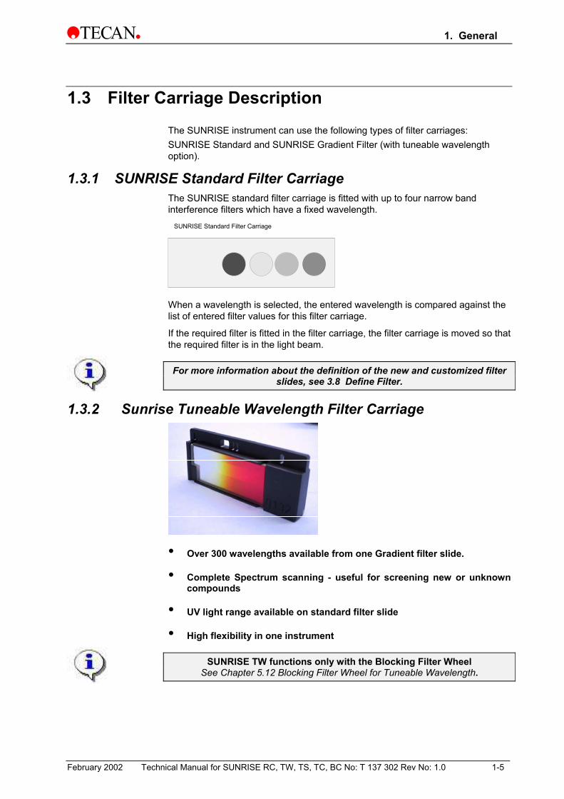
1.3 Filter Carriage Description The SUNRISE instrument can use the following types of filter carriages: SUNRISE Standard and SUNRISE Gradient Filter (with tuneable wavelength option).
1.3.1 SUNRISE Standard Filter Carriage The SUNRISE standard filter carriage is fitted with up to four narrow band interference filters which have a fixed wavelength.
SUNRISE Standard Filter Carriage
When a wavelength is selected, the entered wavelength is compared against the list of entered filter values for this filter carriage.
If the required filter is fitted in the filter carriage, the filter carriage is moved so that the required filter is in the light beam.
For more information about the definition of the new and customized filter slides, see 3.8 Define Filter.
1.3.2 Sunrise Tuneable Wavelength Filter Carriage
• Over 300 wavelengths available from one Gradient filter slide.
• Complete Spectrum scanning - useful for screening new or unknown compounds
• UV light range available on standard filter slide
• High flexibility in one instrument
SUNRISE TW functions only with the Blocking Filter Wheel See Chapter 5.12 Blocking Filter Wheel for Tuneable Wavelength.
February 2002 Technical Manual for SUNRISE RC, TW, TS, TC, BC No: T 137 302 Rev No: 1.0 1-5

1. General
1.3.3 Software Features
SUNRISE Remote Control is intended for use with only external software.
Sunrise Touchscreen is a stand alone device, that works with windows CE.
For more information about the software features, see the appropriate individual manuals. For example: refer to the Magellan Reference manual.
1.4 Instrument Features Microplates can be measured using the following features:
• Various measurement modes
• Single or dual wavelength measurements
• Microplate shaking
• Temperature controlled Incubation
1.4.1 Measurement Modes The instrument can be set to use the following measurement modes:
Fast Plate transport is moved quickly under the measurement diodes so that a fast measurement is obtained. (Default setting).
Accurate Plate transport is moved slowly under the measurement diodes so that a very accurate measurement is obtained.
Center This option measures the optical density only at the center of the well.
With the Fast and Accurate measurement modes, the optical density is measured at three positions across the wells and the average measured optical density value from the three measurements is used as the optical density of the well.
The accurate measurement cycle should always be used when measuring high optical densities.
The Center measurement mode should be used if the liquid in the microplate produces a high meniscus, as an incorrect optical density could be obtained if the optical density is measured at three positions. If an Agglutination measurement is performed, all the measurement positions are used.
For more information about setting the measurement mode, see 3.9 Defining the SUNRISE Instrument Settings.
1-6 Technical Manual for SUNRISE RC, TW, TS, TC, BC No: T 137 302 Rev No: 1.0 February 2002

1. General
1.4.2 Microplate Shaking The SUNRISE is able to shake the microplate before it is measured. Use external software (for example: Magellan) to set the shaking modes.
The microplate can also be shaken between each of the kinetic measurement cycles.
When using a 96 well plate, spillage may occur if the wells are filled with more than 300µl, while using high shaking mode.
1.5 Instrument Accessories The table below contains the order numbers for instrument accessories:
Part Name Part Order Number
Halogen lamp. ................................................................................ 3 709 008 Reader to external computer cable................................................ 3 350 005 QC Pac 2 for SUNRISE and SPECTRA........................................B 037 358 Additional filter slide .......................................................................B 036 301 Memory card .............................................................................B 037 359 01 Flash card for Magellan Windows CE (English) ............................S 039 351 TS - Pen .........................................................................................B 037 360 Barcode Upgrade Kit......................................................................S 039 386 Sunrise Service tool kit ..................................................................S 039 341
Computer Software for Personal Computer Related Software Part of Reader PC Package:
Software Functionality
Magellan Instrument control and data reduction
XRead Plus Instrument control and transfer of raw data to Excel.
SUNRISE instrument setting Enables settings of SUNRISE instrument (SUNRISE, SPECTRA, ATC mode and so on).
RDR Download Enables Download of new firmware from PC to reader.
SUNRISE Error Diagnosis Creates printout of instrument status for service purposes.
Sunset Software
For servicing the sunrise and performing all instrument adjustments (only for trained/ certified persons!)
February 2002 Technical Manual for SUNRISE RC, TW, TS, TC, BC No: T 137 302 Rev No: 1.0 1-7


2. Installation Procedure
2. Installation Procedure
2.1 Introduction This chapter contains the necessary information for installing the instrument.
The installation procedures involve unpacking, environmental requirements, power requirements and interfacing.
2.2 Unpacking and Inspection The delivered instrument is shipped in one carton, which includes:
Power cable
Computer connection cable
SUNRISE Operating manual, XRead Plus manual
Spare fuses
A software CD, which also contains the XRead Plus program and Magellan demo program (30 day working license).
Accessory box
Foam Packaging Foam Packaging
Instrument
February 2002 Technical Manual for SUNRISE RC, TW, TS, TC, BC No: T 137 302 Rev No: 1.0 2-1

2. Installation Procedure
2.2.1 Unpacking Procedure 1. Visually inspect the container for damage, before opening it.
Report any damage immediately.
2. Place the carton in an upright position and open it.
The Cartridge and Filter Block Compartment is fixed with adhesive tape.
3. Lift the instrument out of the carton and place it on a flat surface, free from dust, vibration and away from direct sunlight.
4. Visually inspect the instrument for loose, bent or broken parts.
Report any damage immediately.
5. Compare the instrument's serial number, attached on the rear panel of the instrument, against the serial number of the instrument, on the delivery (shipping) note.
6. Check the instrument accessories against the delivery (shipping) note.
7. Open the plate support area cover and remove the foam strip that is used as the microplate transport lock.
8. Please save all packing materials, as it may be required for later transportation.
2.3 Power Requirements The instrument is auto sensing for the supplied voltage, and therefore does not have to be set for the correct voltage.
Connect the instrument only to a electricity supply system with protective earth.
WARNING TO PREVENT THE RISK OF FIRE, THE MAINS FUSES SHOULD ONLY BE
REPLACED WITH THE SAME TYPE AND RATING OF FUSES.
2.4 Environmental Requirements The instrument should be placed on a flat, level surface that is free from dust, solvents and acidic vapors.
Vibration and direct sunlight must be avoided, to ensure correct results.
2-2 Technical Manual for SUNRISE RC, TW, TS, TC, BC No: T 137 302 Rev No: 1.0 February 2002

2. Installation Procedure
2.5 Instrument Installation Procedure The following procedures detail the necessary steps to be followed when installing the instrument.
WARNING BEFORE THE INSTRUMENT IS INSTALLED AND SWITCHED ON, IT SHOULD
BE LEFT TO STAND FOR AT LEAST THREE HOURS, SO THERE IS NO POSSIBILITY OF CONDENSATION CAUSING A SHORT CIRCUIT.
When the requirements above have been met, installation is carried out using the following procedure:
1. Place the instrument into the required position.
Ensure that the distance between the back panel of the instrument and the wall, is at least 10 cm.
2. Connect the instrument to the external computer with the required interfacing cable.
The interfacing cable is connected into the 9 pin serial interface socket, in the back panel.
3. Ensure that the mains power switch in the back panel of the instrument is in the off position.
4. Insert the power cable into the mains power socket in the back panel.
5. Switch the instrument on using the mains power switch in the back panel.
The instrument is now ready to measure microplates.
2.5.1 Installation of Instrument Control Software
For more information about installing the software, see Magellan or XRead Plus manual, which can be found on the TECAN Reader PC Package CD.
February 2002 Technical Manual for SUNRISE RC, TW, TS, TC, BC No: T 137 302 Rev No: 1.0 2-3


3. Firmware and Software Description
3. Firmware and Software Description
3.1 Rdr Download Software This program enables the user to Download a new Firmware:
The Rdr Download software is installed using the following procedure:
• Insert TECAN Reader PC package CD into the required CD ROM drive.
• The Main menu is displayed. Click the Software button. Click the Setup button for the Firmware Download. The installation program is started.
• A series of dialog boxes will appear, read each one, enter any necessary information and click Next to continue. The files are then installed and the program icon is created.
• When the Installation Complete dialog box appears, click Finish and the Firmware Download program is ready to be used.
February 2002 Technical Manual for SUNRISE RC, TW, TS, TC, BC No: T 137 302 Rev No: 1.0 3-1

3. Firmware and Software Description
3.1.1 Starting the Firmware Download If an instrument is already connected to one of TECAN's programs, close the program or disconnect the instrument from the program.
To start the Firmware Download Software click the RdrDownload icon on the desktop or click the Start button on the lower taskbar and select Programs – TECAN and select Rdr Download. . The following dialog box is displayed:
Click Connect Instrument… to establish a link from the instrument to the computer.
The Setup Port dialog box appears:
Select <Find any> and click OK.
3-2 Technical Manual for SUNRISE RC, TW, TS, TC, BC No: T 137 302 Rev No: 1.0 February 2002
3. Firmware and Software Description
3.1.2 Open file
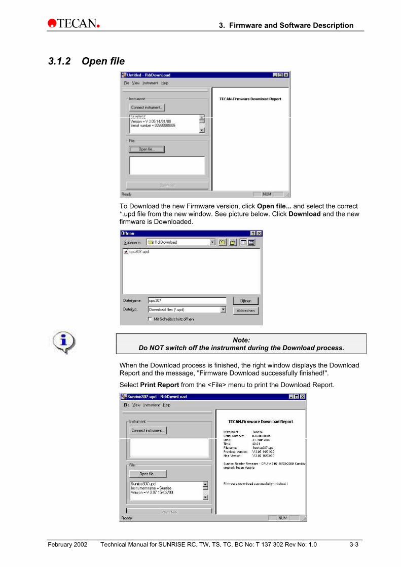
To Download the new Firmware version, click Open file... and select the correct *.upd file from the new window. See picture below. Click Download and the new firmware is Downloaded.
Note: Do NOT switch off the instrument during the Download process.
When the Download process is finished, the right window displays the Download Report and the message, "Firmware Download successfully finished!".
Select Print Report from the <File> menu to print the Download Report.
February 2002 Technical Manual for SUNRISE RC, TW, TS, TC, BC No: T 137 302 Rev No: 1.0 3-3

3. Firmware and Software Description
3.2 Rdr OLE Server This program enables the user to define the settings of:
Instrument modes
Filter definition
Measurement modes
3.2.1 Installation of Instrument Control Software
For more information about installing the software, see Magellan or XRead Plus manual,
which can be found on the TECAN Reader PC Package CD.
3.3 Sunrise Instrument Settings This program enables the user to define the settings of:
Instrument modes
Filter definition
Measurement modes
3.3.1 Installation of SUNRISE Instrument Settings Software The SUNRISE Instrument Settings software is installed using the following procedure:
• Insert TECAN Reader PC package CD into the required CD ROM drive.
• The Setup dialog box is displayed. Click the Service and Settings button. Click the Setup button for the SUNRISE Instrument Settings. The installation program is started, and the SUNRISE Instrument Settings are installed.
• A series of dialog boxes will appear, read each one, enter any necessary information and click Next to continue.
• The files are then installed and the program icon is created.
• When the Installation Complete dialog box appears, click Finish and the SUNRISE Instrument Settings program is ready to be used.
3-4 Technical Manual for SUNRISE RC, TW, TS, TC, BC No: T 137 302 Rev No: 1.0 February 2002

3. Firmware and Software Description
3.3.2 Starting the SUNRISE Instrument Settings In case an instrument is already connected to one of TECAN's programs, close the program or disconnect the instrument from the program.
Click the SUNRISE Instrument Settings icon on the desktop, if present, or click the Start button on the lower taskbar and select Programs – TECAN and select SUNRISE Instrument Settings.
The following dialog box is displayed:
Select the correct communication port and the baudrate. Click Next.
3.3.3 Define Instrument Mode The following dialog box is displayed:
To use the instrument with software designed for former TECAN readers, select the appropriate instrument modes and baudrate. Click Next.
Sunrise mode It is recommended to use the SUNRISE mode with 9600 baud.
Spectra mode Simulates a SPECTRA Reader.
Rainbow mode Simulates a Rainbow Reader
ATC mode Simulates an ATC Reader.
February 2002 Technical Manual for SUNRISE RC, TW, TS, TC, BC No: T 137 302 Rev No: 1.0 3-5

3. Firmware and Software Description
3.3.4 Define Filter The following dialog box is displayed:
Click the Filter slide Out button to move the filter out of the instrument.
To insert a filter slide, open the filter compartment manually and slide the filter into the slot, so that the filter end of the slide is inserted first. (Do not force the filter slide into the instrument beyond the point of resistance).
Click the Filter slide In button and the filter is inserted.
Pos1 - 4 show the filter values for the currently loaded absorbance filters.
The instrument is able to recognize predefined filter slides and the filter values for these slides must not be changed. However, if the filters in the
filter slide have been changed (by a service engineer) or if a new undefined customized filter slide is to be used, the filter slides need to be
defined.
To define the filter values for a new filter slide, enter the required wavelengths in the text boxes. Click Next.
The wavelength range for the SUNRISE is 340 - 750 nm. It is not possible to define the tuneable wavelength filter slide from the
Sunset Instrument Settings
3-6 Technical Manual for SUNRISE RC, TW, TS, TC, BC No: T 137 302 Rev No: 1.0 February 2002

3. Firmware and Software Description
3.3.5 Define Measurement Mode The following dialog box is displayed:
Select the appropriate measurement mode.
Click Finish and the following dialog box is displayed:
The measurement mode has now been set successfully.
If the filter values for the new filter slide has been defined, then the following dialog box is displayed:
February 2002 Technical Manual for SUNRISE RC, TW, TS, TC, BC No: T 137 302 Rev No: 1.0 3-7

3. Firmware and Software Description
3.4 SunSet Software (Service tool kit is necessary!) This program enables the user to adjust the instrument:
Device configuration Lamp adjust Plate calibration Measurement offsets User configuration
3.4.1 Installation of SUNSET Software The SunSet Software is installed using the following procedure:
• Double click the setup icon to automatically install the SunSet software or click the Start button on the lower taskbar and select <Run…> from the menu and then browse for the correct setup file.
• A series of dialog boxes will appear, read each one, enter any necessary information and click Next to continue.
• The files are then installed and the program icon is created.
• When the Installation Complete dialog box appears, click Finish and SunSet Software is operational.
3.4.2 Starting the SunSet Software
• Perform the Sunset test with filterslide G or filterslide A.
• Filterslide G ensures that the entire wavelength range is checked (340 - 750 nm)
• It is not possible to do the adjustments with the Tuneable Wavelength filterslide.
If an instrument is already connected to one of TECAN's programs, close the program or disconnect the instrument from the program.
To start the SunSet Software click the Start button on the lower taskbar and select Programs and then TECAN –from the menus and select SunSet or click the SunSet icon in the directory C:\Programme\Tecan\SunSet.
The following dialog box is displayed:
Select Connect from the Setup menu or press <Strg> and <F5> together to connect the instrument.
3-8 Technical Manual for SUNRISE RC, TW, TS, TC, BC No: T 137 302 Rev No: 1.0 February 2002

3. Firmware and Software Description
The Setup Port dialog box appears. Select <Find any> and click OK
The SunSet Software shows the connection to the reader. The reader type, Serial No., date and time are displayed:
Select Setup all from the <Setup> menu to adjust the instrument.
February 2002 Technical Manual for SUNRISE RC, TW, TS, TC, BC No: T 137 302 Rev No: 1.0 3-9

3. Firmware and Software Description
3.4.3 Device configuration The following dialog box is displayed. Correct or accept the default values and click OK.
3.4.4 Mirror and lamp adjustment Select Lamp adjust… from the <Setup> menu. The following dialog box is displayed:
Select the first filter and click Start. The dialog box shows the minimum and maximum values in percent (%). Adjust the three screws until the minimum and the maximum percentage values lie in the lowest range possible. Click Poti adjust to adjust the amplification. The software adjusts the potis automatically and checks that the minimum and maximum percent values are between a minimum 58 and maximum 89 percent(%). The following picture shows the three screws for adjusting the mirror:
3-10 Technical Manual for SUNRISE RC, TW, TS, TC, BC No: T 137 302 Rev No: 1.0 February 2002

3. Firmware and Software Description
Click Poti check again to check and adjust the other filters (adjustment is done automatically by the software. The values should not be higher than 55 %.)
Make sure the values are correct for all of the available filters on the filter slide. If the values are within the correct range, click Close to return to the Mirror and Lamp Adjust dialog box.
If the values are too far apart, and it is not possible to get better results, the fiber optic must be replaced. See chapter 5.10 Replacing the Fiber Bundle.
3.4.5 Plate calibration Select Plate calibration… from the <Setup> menu. The following dialog box is displayed:
Select a filter and click Start to calibrate the plate transport. The <home to fixed out> and the <home to fixed in> values calibrate the in and out movement. <home to full dark edge> is a white-dark position on the plate carrier and is adjusted by the light beam. It counts the steps from the home to the dark edge position. The <home to rear> shows the number of steps from the home to the rear plate transport position. This adjustment is required to locate all the wells on a MTP plate correctly.
February 2002 Technical Manual for SUNRISE RC, TW, TS, TC, BC No: T 137 302 Rev No: 1.0 3-11

3. Firmware and Software Description
3.4.6 Measurement offset (Inhouse plate is necessary) Select Measurement offsets from the <Setup> menu and the following dialog box is displayed:
Click Start to start the adjustment. The plate carrier moves out and the following dialog box is displayed:
Insert the Inhouse plate with the “A1” positioned top left and click OK. The instrument starts the measurement and adjusts all the values.
Click Show Data and the following dialog box is displayed:
After the measurement the window shows the offset values. Click OK to return to the Measurement Offset dialog box and click OK again to go to the next step.
3-12 Technical Manual for SUNRISE RC, TW, TS, TC, BC No: T 137 302 Rev No: 1.0 February 2002

3. Firmware and Software Description
3.4.7 User configuration Select User configuration… from the <Setup> menu. The following dialog box is displayed:
In this dialog box the Options, RC mode and filters can be defined. In the <Options> area activate the installed options by selecting the appropriate checkbox (Barcode, Temperature control, Touchscreen).
Caution If an option is activated that is not available, the instrument will
not function properly!
When using the Tuneable Wavelength option you must enter the filter table values in the Gradient filter text boxes and you must also enter the Filter slide ID number of the gradient filter slide. If more standard filters are used, define the filters under Filter definitions. After all of the information has been correctly entered, click OK.
The filter slide moves out and the following dialog box is displayed:
Insert the appropriate filter slide and click OK. The filter slide moves in and all of the defined filters are adjusted. If more filter slides are defined the instrument adjusts all of the slides. It will request each filter slide in turn, as in the above dialog box.
February 2002 Technical Manual for SUNRISE RC, TW, TS, TC, BC No: T 137 302 Rev No: 1.0 3-13

3. Firmware and Software Description
3.4.8 SunSet Options Menu
The <Options> menu has the following options:
• Filter control…
• Plate Movements…
• Duration test…
Filter control To move the filter slide perform the following procedure:
Select Filter control… from the <Options> menu and the following dialog box is displayed:
Click Eject to move the Absorbance filter slide out of the instrument.
To insert a filter slide, open the filter compartment manually and place the filter in the instrument so that the filter end of the slide is inserted first.
Click Insert to move the Absorbance filter slide in. The filters can now be defined in the User configuration dialog box (Under Setup, select User configuration…)
When all the required movements have been performed, click OK to end.
3-14 Technical Manual for SUNRISE RC, TW, TS, TC, BC No: T 137 302 Rev No: 1.0 February 2002

3. Firmware and Software Description
Plate Movements To move the plate carrier perform the following procedure:
Select Plate Movements… from the <Options> menu and the following dialog box is displayed:
To move the plate carrier out, click Eject Plate. To move the plate carrier in, click Insert Plate. The plate carrier is automatically positioned correctly. When a measurement is started the plate moves into the instrument.
When all the required movements have been performed, click OK to end.
Duration test To perform a duration test use the following procedure:
Select Duration test… from the <Options> menu and the following dialog box is displayed:
Select the number of cycles (e.g. to 200). Click Start to start the duration test.
If the barcode option is activated, a microplate with a barcode can be inserted and will be used for the Duration test. Enter the Barcode number in the Details: textbox next to the word 'Barcode:'
When the Duration test is finished, the Status window shows the numbers of cycles and errors, if any.
February 2002 Technical Manual for SUNRISE RC, TW, TS, TC, BC No: T 137 302 Rev No: 1.0 3-15

3. Firmware and Software Description
3.5 Sunrise Diagnosis Tool
Note: For more detailed information see Chapter 9.3 Sunrise Diagnosis Software
This program enables the user to print out the data regarding the installed options, adjustment and the last ten errors of the instrument:
• Connect
• Get diagnosis information
• Duration test
• Print report
3.5.1 Installation of Sunrise Diagnosis Tool The Sunrise Diagnosis Tool is installed using the following procedure:
• Double click the setup icon. The Sunrise Diagnosis Tool is installed automatically.
• or from the Start menu (click the Start button on the lower task bar), select Run and browse the directories to find the correct setup file.
• A series of dialog boxes will appear, read each one, enter any necessary information and click Next to continue.
• The files are then installed and the program icon is created.
• When the Installation Complete dialog box appears, click Finish. The Sunrise Diagnosis Tool is now operational.
3-16 Technical Manual for SUNRISE RC, TW, TS, TC, BC No: T 137 302 Rev No: 1.0 February 2002

3. Firmware and Software Description
3.5.2 Connect instrument If an instrument is already connected to one of TECAN's programs, close the program or disconnect the instrument from the program.
The Sunrise Diagnosis Tool is started by clicking the SunDiag icon on the desktop, if present, or go to Start – Programs – TECAN – and select SunDiag.
The following dialog box is displayed:
From the command menu of the Sunrise Diagnosis Tool dialog box select Connect… from the <Test> menu.
The Setup Port dialog box appears:
Select <Find any> and click OK
February 2002 Technical Manual for SUNRISE RC, TW, TS, TC, BC No: T 137 302 Rev No: 1.0 3-17

3. Firmware and Software Description
3.5.3 Get Diagnosis Information Press <F5> and the instrument performs a diagnostic cycle. An explanation of the results is found in the Appendix.
Select Get diagnosis information from the <Test> menu to transfer the diagnostic data from the instrument to the computer.
3.5.4 Duration test To perform a duration test use the following procedure:
Select Duration test… from the <Options> menu and the following dialog box is displayed:
Select the number of cycles (e.g. to 200). Click Start to start the duration test.
If the barcode option is activated, a microplate with a barcode can be inserted and will be used for the Duration test. Enter the Barcode number in the Details: textbox next to the word 'Barcode:'
When the Duration test is finished, the Status window shows the numbers of cycles and errors, if any.
3-18 Technical Manual for SUNRISE RC, TW, TS, TC, BC No: T 137 302 Rev No: 1.0 February 2002
3. Firmware and Software Description
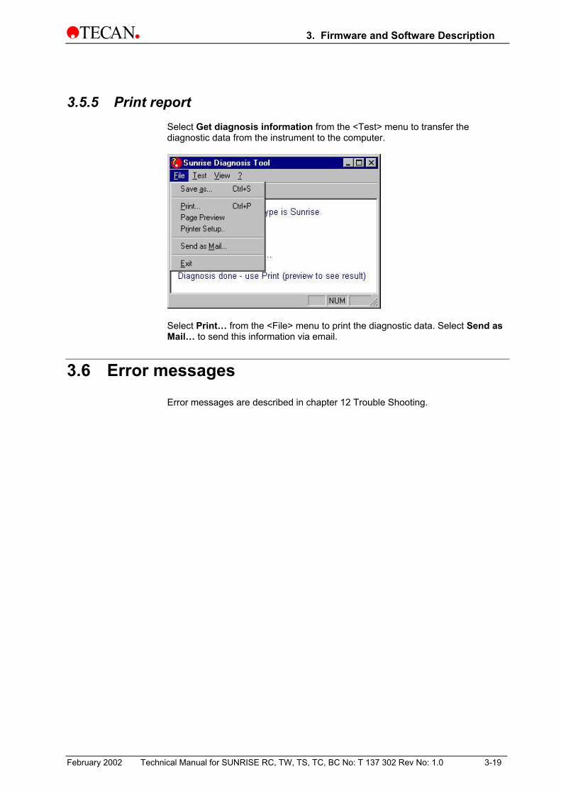
3.5.5 Print report Select Get diagnosis information from the <Test> menu to transfer the diagnostic data from the instrument to the computer.
Select Print… from the <File> menu to print the diagnostic data. Select Send as Mail… to send this information via email.
3.6 Error messages Error messages are described in chapter 12 Trouble Shooting.
February 2002 Technical Manual for SUNRISE RC, TW, TS, TC, BC No: T 137 302 Rev No: 1.0 3-19


4. Removing and Replacing the Instrument Cover
4. Removing and Replacing the Instrument Cover
4.1 Removal of Instrument Top Cover The instrument top cover is removed using the following procedure:
Switch the instrument OFF.
Remove the main power supply cable from the socket.
Remove the four cover screws on the back panel.
February 2002 Technical Manual for SUNRISE RC, TW, TS, TC, BC No: T 137 302 Rev No: 1.0 4-1

4. Removing and Replacing the Instrument Cover
Carefully pull the instrument cover backwards, approx 1-2 cm and lift upwards to remove.
Carefully remove the E-Pack top cover.
4-2 Technical Manual for SUNRISE RC, TW, TS, TC, BC No: T 137 302 Rev No: 1.0 February 2002

4. Removing and Replacing the Instrument Cover
4.2 Removal of the Front Cover
The front panel is removed using the following procedure:
Switch off the instrument and disconnect it from the mains supply.
Remove the lamp compartment cover by gently pulling it from the underside.
Remove the four screws in the right hand side cover area.
Open the plate opening lid and remove the screw in the top left hand corner.
Open the filter compartment lid and remove the screw on the bottom left hand side.
Ensure that the catch and cover do not become damaged.
Plate Support Lid
Cartridge / Filter Compartment Lid
LampCompartment Lid
POWER
front panel screws
February 2002 Technical Manual for SUNRISE RC, TW, TS, TC, BC No: T 137 302 Rev No: 1.0 4-3
4. Removing and Replacing the Instrument Cover
4.3 Replacing the Front Cover
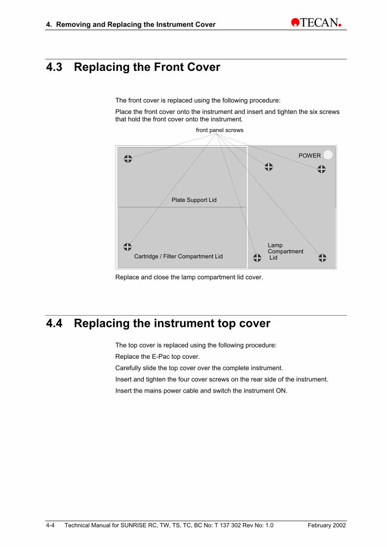
The front cover is replaced using the following procedure:
Place the front cover onto the instrument and insert and tighten the six screws that hold the front cover onto the instrument.
Plate Support Lid
Cartridge / Filter Compartment Lid
LampCompartment Lid
POWER
front panel screws
Replace and close the lamp compartment lid cover.
4.4 Replacing the instrument top cover The top cover is replaced using the following procedure:
Replace the E-Pac top cover.
Carefully slide the top cover over the complete instrument.
Insert and tighten the four cover screws on the rear side of the instrument.
Insert the mains power cable and switch the instrument ON.
4-4 Technical Manual for SUNRISE RC, TW, TS, TC, BC No: T 137 302 Rev No: 1.0 February 2002

4. Removing and Replacing the Instrument Cover
4.5 Removal of Touchscreen The instrument top cover with Touchscreen is removed using the following procedure:
Switch the instrument OFF.
Remove the main power supply cable from the socket.
Remove the four cover screws from the back panel.
Carefully pull the instrument cover backwards, approx 1-2 cm and lift upwards to remove.
February 2002 Technical Manual for SUNRISE RC, TW, TS, TC, BC No: T 137 302 Rev No: 1.0 4-5
4. Removing and Replacing the Instrument Cover
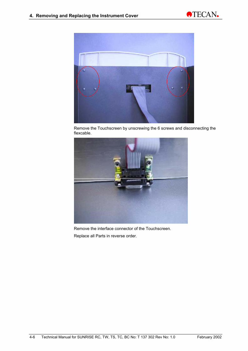
Remove the Touchscreen by unscrewing the 6 screws and disconnecting the flexcable.
Remove the interface connector of the Touchscreen.
Replace all Parts in reverse order.
4-6 Technical Manual for SUNRISE RC, TW, TS, TC, BC No: T 137 302 Rev No: 1.0 February 2002

5. Optical System
5. Optical System
5.1 Introduction This chapter contains the description of the optical system and how the parts are to be exchanged and adjusted. This chapter refers only to the Sunrise Remote Control Reader. For additional information about options like Tuneable Wavelength, please refer to Chapter 9: Description of Options.
Whenever parts of the optical system are changed, check the adjustment of the system and perform QC-Pac II test to be sure that the instrument is working properly.
5.2 Optical System Description The Powerboard supplies a voltage to the halogen lamp. To eliminate the IR light above 750 nm, a heat absorbance filter is installed after the mirror. The light beam is then reflected by the mirror. The beam passes from the mirror to the optical lens.
The focused beam is passed through the wavelength filter so that the correct wavelength of light is obtained.
After passing through the filter the beam falls onto the fiber optic unit which distributes the available light into the 13 beams: 12 measurement beams and a reference beam.
The fiber optic unit projects the 12 narrow measurement light beams upwards through a row of the sample wells in the microplate.
The reference beam is passed through a hole in the transport box to the reference diode which measures and controls the amount of light that passes through the filter.
The reference diode is used to keep the level of light that passes through the filter constant for each measurement and filter. The light level is kept constant by altering the voltage supplied to the lamp from the Powerboard .
After light beams have passed through the samples they are focused by lens and their intensity is measured by 12 diodes which are located directly above the sample wells, one diode for each row of wells.
The light intensity measured by the 12 diodes, is amplified and converted into a digital value by the Mainboard .
For normal measurements the light intensity is measured on three points on the well each six times. The microprocessor uses these digital values to calculate the Optical Density of the sample.
February 2002 Technical Manual for SUNRISE RC, TW, TS, TC, BC No: T 137 302 Rev No: 1.0 5-1

5. Optical System
5.3 Optical System Diagram The illustration below illustrates the optical system functions.
SUNRISE ST (Option Standard Optic) Instrument
Transport box
Fiber Optic Unit
Filter Carriage Lamp
Mirror
Heat Absorbing Filter
Optical Lens
Reference Diode Channel
Microplate
Main Board
SUNRISE TW (Tuneable Wavelength Optic) Instrument
Photo Diode Block
Diode Lens Block
Fiber Optic Unit
Filter Slide Block Lamp
Mirror
Heat AbsorbingFilter
Optical Lens
Reference Diode Channel
Microplate
A/D Converter Board
Blocking Filter wheel
5-2 Technical Manual for SUNRISE RC, TW, TS, TC, BC No: T 137 302 Rev No: 1.0 February 2002

5. Optical System
5.3.1 Measurements with Wavelengths below 400 nm Measurements with filter values below 400 nm require a higher amplification of the analog signal, because the light intensity of the halogen lamp is very low in this wavelength range.
This amplification is automatically activated by the firmware, when a measurement with the above mentioned filter range is started.
5.3.2 Agglutination Measurement Mask for SUNRISE ST Option The SUNRISE ST instrument can perform Agglutination measurements, where the optical density is measured up to 40 times across each well.
Agglutination Measurement Optical density measured up to 40 times across each well
Agglutination Mask (used for SUNRISE ST)
The SUNRISE ST instrument is fitted with a special mask fitted to the lower part of the transport box so that a very thin beam of light is produced. The agglutination mask is not available as a spare part. As it is fitted to the transport box, the transport box has to be ordered in case this part is faulty.
The Agglutination Mask for the SUNRISE ST is different than the one for the SUNRISE TW.
February 2002 Technical Manual for SUNRISE RC, TW, TS, TC, BC No: T 137 302 Rev No: 1.0 5-3

5. Optical System
5.4 Lamp Replacement
Please note that the instrument specifications can only be guaranteed if genuine TECAN parts are used.
The following steps must be followed to replace the lamp:
Before replacing the lamp let the instrument cool down for at least thirty minutes.
Switch off the instrument and disconnect it from the mains supply.
Lamp Compartment
Remove the lamp compartment cover by gently pulling it from the underside.
Push the locating spring bar, on top of the lamp, to the left.
Carefully remove the lamp from the lamp holder.
To prevent burns, ensure that the lamp is cold.
Disconnect the lamp power cables from the lamp power connector.
Replace the old lamp.
Reconnect the lamp power connector.
Replace the lamp into the lamp holder.
Please note that the lamp is held in place by three lugs, between which the lamp is to be inserted.
Insert the lamp so that the cables are at the bottom.
5-4 Technical Manual for SUNRISE RC, TW, TS, TC, BC No: T 137 302 Rev No: 1.0 February 2002

5. Optical System
Locating Lugs
Lamp
Connecting Plug
Spring bar
Lock the lamp into place using the spring bar.
Before closing the cover plate, ensure, that the lamp is properly seated, in the three lugs.
Close the lamp compartment cover.
Caution Do not touch the reflective surface and the bulb. Any finger prints on these
surfaces must be removed with acetone or methylated spirits.
Caution After replacing the halogen lamp, select Lamp adjust from the Setup menu
to reconfigure the Mirror & Lamp Adjust settings.
5.5 Filter Slide
5.5.1 SUNRISE Filter Slide (standard filter slide) The SUNRISE standard filter slide is fitted with up to 4 narrow band interference filters which have a fixed wavelength.
When a wavelength is selected the instrument then compares the entered wavelength against the list of entered filter values for this filter slide.
If the required filter is fitted in the filter slide, the instrument then moves the filter slide so that the required filter is in the light beam.
February 2002 Technical Manual for SUNRISE RC, TW, TS, TC, BC No: T 137 302 Rev No: 1.0 5-5
5. Optical System
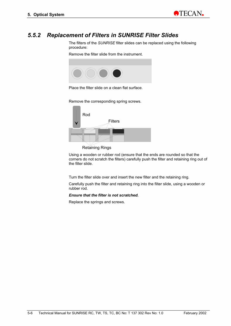
5.5.2 Replacement of Filters in SUNRISE Filter Slides The filters of the SUNRISE filter slides can be replaced using the following procedure:
Remove the filter slide from the instrument.
Place the filter slide on a clean flat surface.
Remove the corresponding spring screws.
RodFilters
Retaining Rings Using a wooden or rubber rod (ensure that the ends are rounded so that the corners do not scratch the filters) carefully push the filter and retaining ring out of the filter slide.
Turn the filter slide over and insert the new filter and the retaining ring.
Carefully push the filter and retaining ring into the filter slide, using a wooden or rubber rod.
Ensure that the filter is not scratched. Replace the springs and screws.
5-6 Technical Manual for SUNRISE RC, TW, TS, TC, BC No: T 137 302 Rev No: 1.0 February 2002

5. Optical System
5.5.3 Filter Coding for SUNRISE Filter Slides For the SUNRISE instrument, 8 different 4-Filter slides (A-H) can be used. The optical sensor on the filter guide detects the letter of filter slide. In the setup menu (see Operating Manual) the values of each individual filter fitted in the slides need to be defined.
For coding the slides, slits are used, situated on top of the slide.
When a new empty slide is ordered, all coding slits are closed, therefore, the filter slide must be defined manually by opening slits as shown below.
Example Coding Slits Home Slit 1.Position slit
The first 2 slits are used to define the slide type ( 4-filter or gradient).
The second 6 slits are used to define the filter slide (A-H)
The third (bigger) slide is the home position slide.
The slits in the fourth part of the filter are used to define the position of each filter fitted in the slide by using the optical switch.
February 2002 Technical Manual for SUNRISE RC, TW, TS, TC, BC No: T 137 302 Rev No: 1.0 5-7
5. Optical System
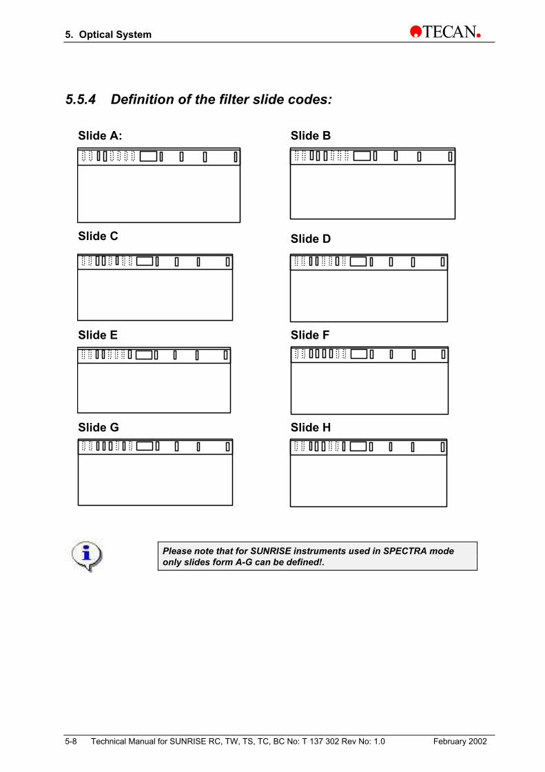
5.5.4 Definition of the filter slide codes:
Slide A: Slide B
Slide C Slide D
Slide E Slide F
Slide G Slide H
Please note that for SUNRISE instruments used in SPECTRA mode only slides form A-G can be defined!.
5-8 Technical Manual for SUNRISE RC, TW, TS, TC, BC No: T 137 302 Rev No: 1.0 February 2002

5. Optical System
5.6 Filter slide ( Tuneable wavelength)
With the gradient filter slide, measurements can be made from 400 nm to 700 nm using only one filter slide. There are over 300 wavelengths available from one gradient filter slide. Complete Spectrum scanning - useful for screening new or unknown compounds. The gradient filter slide makes the instrument highly flexible.
The following adjustments are necessary for using the gradient filter slide with the sunset software:
• Select reader type
• Check Serial Number
• Enter the gradient filter values
• Enter Filter slide ID number
• Set Calibration values (determined by the filter slide)
It is necessary to set the instrument to Sunrise tuneable wavelengths, because the Powerboard of the SUNRISE TW is controlled differently than the Powerboard in the SUNRISE ST. The main difference is that the TW instrument has a stepper motor to move the filter slide and the ST instrument has a DC motor.
February 2002 Technical Manual for SUNRISE RC, TW, TS, TC, BC No: T 137 302 Rev No: 1.0 5-9

5. Optical System
s
The TW filtersrelationships oon the TW filtethe text box nown ID numbe
5-10 Technical Manual for SUNRISE RC
Filter slide ID
lide comes delivered with a calibf the various wavelengths with thrslide. In the Gradient filter area
ext to the appropriate wavelengthr. In the Filter slide ID area, ent
, TW, TS, TC, BC No: T 137 302 Re
Calibration value
ration sheet. This sheet lists the e position of these wavelengths , enter the gradient filter values in values. Each TW filterslide has its er this number.
v No: 1.0 February 2002

5. Optical System
5.7 Lamp and Mirror Unit Parts The lamp and mirror unit consists of the following serviceable parts:
• Heat Filter
• Air Filter
• Mirror
• Optical Lens
To service these parts the following procedures have to be executed:
5.7.1 Heat Filter and Air Filter • Switch the instrument OFF
• Remove the main power cable from the socket
• Remove Lamp Compartment Cover
• Remove Lamp
• Install new Heat filter.
• To replace the Air filter, pry open the plastic cover with a screw driver and replace the filter.
• Replace Lamp
• Close Lamp Compartment Cover
Heat filter
Air filter Filter cover
February 2002 Technical Manual for SUNRISE RC, TW, TS, TC, BC No: T 137 302 Rev No: 1.0 5-11

5. Optical System
5.7.2 Mirror, Optical Lens • Switch the instrument OFF
• Remove the main power cable from the socket
• Remove Top cover and upper EPAC (see Chapter 4)
• Remove Front Cover
• Remove Power Board
• Disconnect ST1, ST8,ST7,ST3,ST15,ST20 andST 21 of Mainboard and all connections of the of Powerboard
• Disconnect Fiber from the Filter Guide
• Remove the Transport Box
For Mirror Replacement: • Open the mirror housing top cover
• Remove Lamp and Heatfilter
• Remove 3 adjusting screws and the
• spring loaded fixing screw
• Replace New Mirror
5-12 Technical Manual for SUNRISE RC, TW, TS, TC, BC No: T 137 302 Rev No: 1.0 February 2002
5. Optical System
For Optical Lens Replacement • Remove EPAC Filter Guide
• Replace Optical Lens
• Replace all Parts in reverse order. Check Mirror Adjustment and Diode counts and adjust if necessary ( See chapter 3 for detailed information).
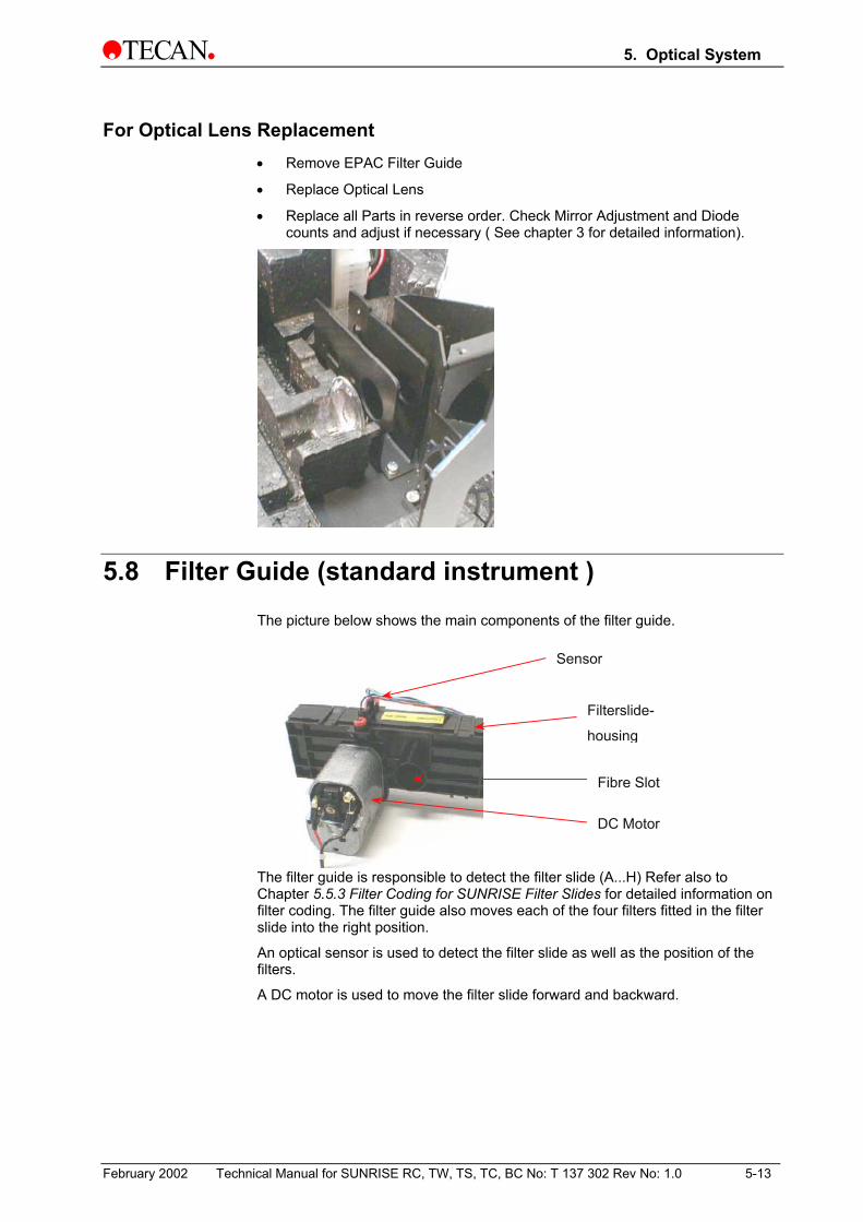
5.8 Filter Guide (standard instrument ) The picture below shows the main components of the filter guide.
Sensor
Fibre Slot
DC Motor
Filterslide-
housing
The filter guide is responsible to detect the filter slide (A...H) Refer also to Chapter 5.5.3 Filter Coding for SUNRISE Filter Slides for detailed information on filter coding. The filter guide also moves each of the four filters fitted in the filter slide into the right position.
An optical sensor is used to detect the filter slide as well as the position of the filters.
A DC motor is used to move the filter slide forward and backward.
February 2002 Technical Manual for SUNRISE RC, TW, TS, TC, BC No: T 137 302 Rev No: 1.0 5-13

5. Optical System
The only serviceable parts are the optical sensor and the whole filter guide. For replacing these parts please refer to the following procedure:
• Switch the instrument OFF
• Remove the main power cable from the socket
• Remove Top cover and upper EPAC (see Chapter 4)
• Remove Front Cover
• Remove Power Board
• Disconnect ST1, ST8,ST7,ST3,ST15,ST20 and ST 21 of Mainboard and all connections of the of Powerboard
• Remove the Power board
• Disconnect Fiber from the Filter Guide
• Remove the Transport Box
• Remove EPAC Filter Guide
• Replace either sensor or complete filter guide
• Replace all Parts in reverse order
5-14 Technical Manual for SUNRISE RC, TW, TS, TC, BC No: T 137 302 Rev No: 1.0 February 2002

5. Optical System
5.9 Filter Guide ( Tuneable Wavelength):
Sensor
Filterslide housing
Fiber slot
DC-Servo motor
For replacing these parts please refer to the following procedure:
• Switch the instrument OFF
• Remove the main power cable from the socket
• Remove Top cover and upper EPAC (see Chapter 4)
• Remove Front Cover
• Remove Power Board
• Disconnect ST1, ST8, ST7, ST3, ST15, ST20 and ST 21 from the Mainboard and all connections of the of Powerboard
• Remove the Power board
• Disconnect Fiber from the Filter Guide
• Remove the Transport Box
• Remove EPAC Filter Guide
• Replace either sensor or complete filter guide
• Replace all Parts in reverse order
February 2002 Technical Manual for SUNRISE RC, TW, TS, TC, BC No: T 137 302 Rev No: 1.0 5-15

5. Optical System
5.10 Fiber Bundle The fiber bundle is fitted directly to the transport box on the one side and fitted to the filter guide on the other side. It consists of 12 measurement fibers and one reference fiber. On both sides the fiber is just clicked in and held in position by pins. In case that the clips on the transport box are broken it is possible to fix the fiber bundle using screws M3X12.
The fiber bundle itself is not serviceable. In case the fiber bundle fails it has to be changed as a complete unit. For replacing this part please refer to the following procedure.
• Switch the instrument OFF
• Remove the main power cable from the socket
• Remove Top cover and upper EPAC (see Chapter 4)
• Remove Front Cover
• Remove Power Board
• Disconnect ST1, ST8,ST7,ST3,ST15,ST20 and ST 21 of Mainboard and all
• connections of the of Powerboard
• Disconnect Fiber from the Filter Guide
• Remove the Transport Box
• Replace new fiber bundle by removing the old one from the transport box.
• Replace all Parts in reverse order
5-16 Technical Manual for SUNRISE RC, TW, TS, TC, BC No: T 137 302 Rev No: 1.0 February 2002

5. Optical System
5.10.1 Difference between Standard Fiber Optic and Tuneable Wavelength Fiber Optic
Sunrise Standard Fiber Optic
Tuneable Wavelength Fiber Optic
r
5.11 Further Parts belonging to the Optical There are additional parts which might belong to the opticalnot serviceable or described in another chapter:
The lower and upper lens are part of the transport box and ncase the lens are faulty the transport box needs to be changto Chapter 6 Mechanical System.
The agglutination mask is also part of the transport box. Thiserviceable part and in case it becomes faulty also the transchanged. Refer to Chapter 6 Mechanical System.
The photo diodes are part of the main board. They are not sTherefore, the main board needs to be changed. Refer to CComponents.
ALL ADJUSTMENT PROCEDURES AFTER EXCHANGING PAPLEASE REFER TO THE RELEVANT CHAP
February 2002 Technical Manual for SUNRISE RC, TW, TS, TC, BC No: T 137 302 Rev
Reference Fiber
Reference FibeSystem system but are either
ot serviceable. In ed. In this case refer
s is also a non port box needs to be
erviceable. hapter 7 Electrical
RTS ARE STILL OPEN. TER
No: 1.0 5-17

5. Optical System
5.12 Blocking Filter Wheel for Tuneable Wavelength • Switch the instrument OFF
• Remove the main power cable from the socket
• Remove Top cover and upper EPAC (see Chapter 4)
• Remove Front Cover
• Remove Power Board
• Disconnect ST1, ST8,ST7,ST3,ST15,ST20 and ST 21 of Mainboard and all connections of the of Powerboard
• Remove the Power board
• Disconnect Fiber from the Filter Guide
• Remove the Transport Box
• Remove EPAC Filter Guide
• Disconnect all connectors on the TW Board
• Remove the TW Board
• Remove the complete filter wheel
Unscrew the two screws on the bottom
Replace all Parts in reverse order
5-18 Technical Manual for SUNRISE RC, TW, TS, TC, BC No: T 137 302 Rev No: 1.0 February 2002

5. Optical System
5.13 Filter Wheel Properties
r
r
5.14
February 2
Dark-blue filter
Mirror for Barcode ScanneThe mirror unit is replaced using the
Switch the instrument OFF.
Remove the main power cable from
Remove the top cover of the instrum
Remove the Epack top cover.
Remove the front cover of the instru
Unscrew the mirror as shown in the
Replace the mirror.
002 Technical Manual for SUNRISE RC, TW, TS, T
Home sensor flag
r following p
the socket
ent.
ment.
picture.
C, BC No: T
Green filte
Light-blue filte
rocedure:
.
Unscrew the two screws to remove the mirror unit.
137 302 Rev No: 1.0 5-19


6. Mechanical System
6. Mechanical System
6.1 Introduction This chapter contains the description of the transport system and how the parts are to be exchanged and adjusted.
6.2 Transport System Description The plate support is moved by a stepper motor via the transport belt.
When the motor is rotated by one step, the plate support is moved 0.0875 mm.
The positioning is controlled by two optical switches: Start and End optical switches.
The Start optical switch is mainly used to set the transport to a zero position, from which the number of steps that are to be performed for positioning the microplate under the measuring diodes, are counted.
The End optical switch is only used if inside shaking is performed before a measurement. During a normal measurement procedure the End optical switch is not used.
The distance between the End and the Start optical switches is measured in steps during the machine set up. The number of steps is stored in the instrument's memory.
The measured number of steps is stored so that the inner sensor can be used for zero calibration after inside shaking has been performed.
This distance can be recalibrated in the Service program using the submenu Calibrate Length.
6.3 Measurement Procedure When the measurement procedure is started, the transport system is moved to the Start optical switch.
The plate support moves back and forth under the measuring diodes. The measurements are performed after a certain number of steps.
After the measurement has been completed, the plate support is returned to the Start optical switch and the instrument checks the number of steps required to reach the Start optical switch. This has to be the same as the number of steps used to measure the microplate.
If the number of steps are different, the instrument displays a transport error message and the measured results are ignored.
February 2002 Technical Manual for SUNRISE RC, TW, TS, TC, BC No: T 137 302 Rev No: 1.0 6-1

6. Mechanical System
Inside Shaking If the microplate is to be measured using inside shaking, the microplate is moved into the instrument when the measurement is started and the shaking is performed.
After the shaking has been performed, the plate support is moved until the End optical switch is detected.
When the End optical has been detected, the microplate is moved under the measurement diodes and measured after the required number of steps.
After the instrument has completed the measurement, the plate support is returned to the Start optical switch. The instrument checks that the number of steps required to reach the Start optical switch is the same as the number of steps stored in the memory for the calibration length.
If the number of steps are different, a transport error message is displayed and the measured results are ignored.
6.4 The Transport Box Assembly
The Transport box is a complete unit which contains all the mechanical parts for the plate transport. This part is not serviceable, if any defects occur the entire unit must be replaced.
The various options require different Transport Box Assemblies, see chapter 13 Spare Parts List for the part
number specific to the instrument.
6-2 Technical Manual for SUNRISE RC, TW, TS, TC, BC No: T 137 302 Rev No: 1.0 February 2002

6. Mechanical System
6.5 Exchanging the Transport Box The transport box is a whole unit and can be replaced using the following procedure:
1. Switch the instrument OFF
2. Remove the main power cable from the socket
1. Remove top cover and upper EPAC (see Chapter 4)
2. Remove front Cover (see Chapter 4)
3. Disconnect ST1, ST8,ST7,ST3,ST15,ST20 and ST 21 of Mainboard and all
connections of the of Powerboard
4. Remove the Power Board and Mainboard
Fe
Front Cover
s
d
Mainboard
Power Boar
5. Disconnect the Fibre bundle from the Filter Guide
bruary 2002 Technical Manual for SUNRISE RC, TW, TS, TC, BC No: T 137 302 Rev No: 1.0
Interconnector
6-3

6. Mechanical System
6. Remove the Transport Box carefully.
7. Remove the fiber bundle from the Transport Box
Note: To avoid damage to the fiber bundle, take care not to bend the fibers when removing from the transport assembly.
6-4 Technical Manual for SUNRISE RC, TW, TS, TC, BC No: T 137 302 Rev No: 1.0 February 2002

6. Mechanical System
6.6 Transport Box Adjustments After the transport system and all other parts have been replaced, to ensure correct alignment of the transport system the following adjustments should be performed using the Sunset Software (as described in Chapter 3).
Plate Calibration
Measurement Offset
Duration Test
6.7 Replacing the Temperature control unit 1. Switch the instrument OFF
2. Remove the main power cable from the socket
3. Remove top cover and upper EPAC (see Chapter 4)
4. Remove front cover (see Chapter 4)
5. Disconnect ST1, ST8, ST7, ST3, ST15, ST20 and ST 21 from Mainboard and all connections to the Powerboard
6. Remove the Power Board and Mainboard
7. Disconnect the Fibre bundle from the Filter Guide
8. Disconnect the Thermoboard and remove the Transport Box carefully
9. Remove the foam rubber cover from the backside of the instrument
10. Disconnect the Flex cable from the Thermo Board on the left side and remove the nozzle plate.
February 2002 Technical Manual for SUNRISE RC, TW, TS, TC, BC No: T 137 302 Rev No: 1.0 6-5

6. Mechanical System
11. Remove the Thermo Board and disconnect all cables on the board.
12. Remove the Peltier module including cooling unit
13. Remove the fans and make a note of the position of each fan, so that it can
be returned to the same location
14. Replace all Parts in reverse order.
6-6 Technical Manual for SUNRISE RC, TW, TS, TC, BC No: T 137 302 Rev No: 1.0 February 2002

7. Electronic System
7. Electronic System
7.1 Introduction This chapter describes the replacement and adjustment procedures for the various electronic parts of the instrument.
This chapter also contains the connection diagrams illustrating how the various parts of the instrument are interconnected.
The instrument contains the following electronic parts:
1. Main Board This is the major board in the instrument and contains the microprocessor and the Analog / Digital converter. The A/D Converter is used to measure the light that is transmitted through the samples. The light is converted into a digital value that is be used to calculate the optical density of the sample.
2. Power Board (standard) This board is used to control the transport motor, filter carriage motor, the 5 volt voltage regulation, the lamp control and for the temperature control of the instrument (fan).
3. Power Board (tuneable wavelength) This board has the same function as the standard board, but there is one more motor driver for controlling the filter carriage motor (DC Servo Motor by TW Option).There is also a voltage regulation for the TW board.
4. TW Board This board is for controlling the tuneable wavelength blocking filter wheel.
5. Thermo Board This board controls the Nozzle-plate, the fans of TC unit, sensors of the TC unit, the upper heating plate in the transport box and to regulate the Peltier module of the Temperature control unit.
6. 12-volt board The board convert the 24 volt input voltage to 24/12 volt output voltage. The 12 volt voltage is to control the Peltier module.
7. Power Supply This unit is used to supply the various voltages that are required by the instrument.
8. Barcode Board This board controls the barcode reader. 9. Optical Switches This section gives the layout and circuit diagrams for the optical switches that are used in the instrument.
February 2002 Technical Manual for SUNRISE RC, TW, TS, TC, BC No: T 137 302 Rev No: 1.0 7-1

7. Electronic System
7.2 Interconnection diagram (standard RC) The diagram below shows how the various parts of the instrument are interconnected.
ST 20
MAIN BOARD POWER BOARD
ST 19
POWER SUPPLY
Mains InputON/OFF Switch
Fuses
ST 15 ST 23
ST 5
ST 6
ST 18ST 22
ST 11
ST 14
ST 12
ST 21
ST 7
ST 2
ST 8ST 1
BOOTEEPROM
CPU
VAN
RS 232PRINTER INTERFACE
TANSPORT MOTOR
TRANSPORT START POSITIONOPTICAL SWITCH
TRANSPORT END POSITIONOPTICAL SWITCH
Filter Carriage Sensor
Motor
LAMP
Power ON LED
GNDChassis
Filter Transport Mechanism
7-2 Technical Manual for SUNRISE RC, TW, TS, TC, BC No: T 137 302 Rev No: 1.0 February 2002

7. Electronic System
7.3 Voltage diagram (standard RC)
black
+24V
red
ST 20
MAIN BOARD POWER BOARD
ST 19
POWER SUPPLY
Mains InputON/OFF Switch
Fuses
ST 15 ST 23
ST 5
ST 6
ST 18ST 22
ST 11
ST 14
ST 12
ST 21
ST 7
ST 2
ST 8ST 1
BOOTEEPROM
CPU
VAN
RS 232PRINTER INTERFACE
TANSPORT MOTOR
TRANSPORT START POSITIONOPTICAL SWITCH
TRANSPORT END POSITIONOPTICAL SWITCH
Filter Carriage Sensor
Motor
LAMP
Power ON LED
GNDChassis
Filter Transport Mechanism
red
+24V black
brown blue
black
+2V
red
red
+12V
black
+24V
red black
+12V
+24V
+2V
+24V
+24V
~220V
February 2002 Technical Manual for SUNRISE RC, TW, TS, TC, BC No: T 137 302 Rev No: 1.0 7-3

7. Electronic System
7.4 Main Board This board is the main board of the instrument and contains the following main components:
CPU chip Boot EPROM chip Battery A/D converter Area
Connector to Power Supply
A/D Converter Area
Processor Boot EPROM
Connector to printer interface
Connector to Powerboard
Connector to
RS 232
Touchscreen connection Battery
N.C Transport start position optical switch connector
Filter carriage sensor connector
Transport end position optical switch connector
Connector for options
N.C.
7-4 Technical Manual for SUNRISE RC, TW, TS, TC, BC No: T 137 302 Rev No: 1.0 February 2002

7. Electronic System
7.5 Replacing the Main Board
The CPU board is exchanged using the following procedure:
Switch the instrument OFF.
Remove the mains power cable from the socket.
Remove the instrument top cover.
Remove the Epack top cover.
Disconnect the Power Board on connector ST20.
Disconnect the three optical switch connectors.
Disconnect the power supply connector on ST21.
Disconnect the connector to printer interface on ST 7.
Disconnect the connector to RS 232 on ST 8.
Remove the three screws as shown in the picture.
Remove thethree screws
Carefully pull the CPU board out of the instrument.
Exchange the CPU board.
Carefully place the new CPU board on the top of the transport box.
Insert and fix the three screws on the main board.
Connect the RS 232 connector on ST8.
Connect the printer interface connector on ST7.
Connect the power supply connector on ST21.
Connect the three optical switch connectors.
Replace the Epack top cover.
Replace the instrument top cover.
Connect the mains power cable to the socket.
Switch the instrument ON.
February 2002 Technical Manual for SUNRISE RC, TW, TS, TC, BC No: T 137 302 Rev No: 1.0 7-5

7. Electronic System
Perform the device configuration with the SunSet software as shown in the picture.
Set the reader type
Perform all adjustments with the SunSet software as des
7-6 Technical Manual for SUNRISE RC, TW, TS, TC, BC No: T 137 302 Rev No: 1.0
Set the serialnumber of theinstrument
cribed in chapter 3.
February 2002

7. Electronic System
7.6 Power Board (standard) This board is used to control the transport motor, filter carriage motor, the 5 volt voltage regulation, the lamp control and for the temperature control of the instrument (fan).
Front side:
Connector to CPU board
R
F
Connector toPower on LED
Connector toLamp
ear side:
ebruary 2002 Technical Manual for SUNRISE RC, TW, TS, TC, BC No: T 137 302 Rev No: 1.0
Connector to filtertransport motor
Connector totransport motor
Connector topower supply
Connector tofan
7-7

7. Electronic System
7.7 Exchanging the Power Board (standard) The power board is exchanged using the following procedure:
Switch the instrument OFF.
Remove the mains power cable from the socket.
Remove the instrument top cover.
Remove the Epack top cover.
Disconnect the Power Board on connector ST20.
Disconnect the lamp connector on ST15.
Disconnect the power on LED connector on ST23.
Disconnect the filter transport motor connector on ST5.
Disconnect the transport motor connector on ST6.
Disconnect the Power supply connector on ST18.
Disconnect the fan connector on ST22.
Carefully pull the Power board out of the instrument.
Exchange the Power board.
Connect the fan connector on ST22.
Connect the Power supply connector on ST18.
Connect the transport motor connector on ST6.
Connect the filter transport motor connector on ST5.
Connect the power on LED connector on ST23.
Connect the lamp connector on ST15.
Connect the power board on connector ST20.
Replace the Epack top cover.
Replace the instrument top cover.
Connect the mains power cable on the socket.
Switch the instrument ON.
7-8 Technical Manual for SUNRISE RC, TW, TS, TC, BC No: T 137 302 Rev No: 1.0 February 2002

7. Electronic System
7.8 Power Board (tuneable wavelength) The board has the same function as the standard board but there is one more motor driver for control the filter carriage motor (DC Servo Motor by TW Option).There is also a voltage regulation for the TW board.
Front view:
Connector to CPU board
Connector to Power on LED
Connector to the lamp
Rear view:
Connector to power supply
C
Connector to fan
February 2002 Technical Manual for SUNRISE RC, TW, TS, TC, BC No: T 137 302 Rev No:
Connector to filter transport
Motor (DC Servo Motor)
onnector to transport motor
1.0 7-9

7. Electronic System
The power board is exchanged using the following procedure:
Switch the instrument OFF.
Remove the mains power cable from the socket.
Remove the instrument top cover.
Remove the Epack top cover.
Disconnect the Power Board on connector ST20.
Disconnect the lamp connector on ST15.
Disconnect the power on LED connector on ST23.
Disconnect the filter transport motor connector on ST5.
Disconnect the transport motor connector on ST6.
Disconnect the Power supply connector on ST18.
Disconnect the fan connector on ST22.
Carefully pull the Power board out of the instrument.
Exchange the Power board.
Connect the fan connector on ST22.
Connect the Power supply connector on ST18.
Connect the transport motor connector on ST6.
Connect the filter transport motor connector on ST5.
Connect the power on LED connector on ST23.
Connect the lamp connector on ST15.
Connect the power board on connector ST20.
Replace the Epack top cover.
Replace the instrument top cover.
Connect the mains power cable on the socket.
Switch the instrument ON.
7-10 Technical Manual for SUNRISE RC, TW, TS, TC, BC No: T 137 302 Rev No: 1.0 February 2002

7. Electronic System
7.9 TW Board This board is for controlling the tuneable wavelength filter wheel.
Motor Filter wheel
The TW Board is exchanged using the following procedure:
Switch the instrument OFF.
Remove the mains power cable from the socket.
Remove the instrument top cover.
Remove the Epack top cover.
Disconnect the Power Board on connector ST20.
Disconnect the lamp connector on ST15.
Disconnect the power on LED connector on ST23.
Disconnect the filter transport motor connector on ST5.
Disconnect the transport motor connector on ST6.
Disconnect the Power supply connector on ST18.
Disconnect the fan connector on ST22.
Carefully pull the Power board out of the instrument.
Disconnect the fiber bundle from the filter guide.
Remove the transport box carefully.
Remove EPAC Filter Guide.
Disconnect all cable connections on the TW Board and exch
Replace all Parts in reverse order.
February 2002 Technical Manual for SUNRISE RC, TW, TS, TC, BC No: T 137 302 Rev
Filter wheel homeposition senor
24 volt powerconnector
Motor driver forfiltr wheel
Option connector toMainboard
ange the board.
No: 1.0 7-11

7. Electronic System
7.10 Thermo Board
The board controls the nozzle plate, the fans of TC unit, sensors of the TC unit, the upper heating plate in the transport box and to regulate the Peltier module of the Temperature control unit.
Peltier power connection
24 volt power connector from 12 volt board
Fan and Peltier modulesensor connector Connector to nozzle
plate
Connector to heatingplate transport box
Connector to Mainboard(option connection)
Boot EPROM Thermoboard Fan connector
The Thermo board is exchanged using the following procedure:
Switch the instrument OFF.
Remove the mains power cable from the socket.
Remove the instrument top cover.
Remove the Epack top cover.
Disconnect all cable connections on the Thermo board.
Exchange the Thermo board.
Replace all Parts in reverse order.
7-12 Technical Manual for SUNRISE RC, TW, TS, TC, BC No: T 137 302 Rev No: 1.0 February 2002

7. Electronic System
7.11 12 Volt Board
The board convert the 24 volt input voltage to 24/12 volt output voltage. The 12 volt voltage is for controlling the Peltier module.
24 volt power connection from the power supply.
Fe
12 /24volt power connector to the thermo board.
The 12 volt board is exchanged using the following procedure:
Switch the instrument OFF.
Remove the mains power cable from the socket.
Remove the instrument top cover.
Remove the Epack top cover.
Remove the power connection socket.
Remove Epack right side cover.
Remove the Power supply.
Disconnect the two cable connections on the 12 volt board.
Exchange the 12 volt board.
Replace all Parts in reverse order.
bruary 2002 Technical Manual for SUNRISE RC, TW, TS, TC, BC No: T 137 302 Rev No: 1.0 7-13

7. Electronic System
7.12 Power Supply board The power supply unit supplies the + 24 Volt voltage that is required by the instrument.
Supply voltage for CPU Board ( + 24V)
Supply voltage for the power Board (+ 24V)
Fuse
Connector to Main power socket
Connector to CPU board and power board
7-14 Technical Manual for SUNRISE RC, TW, TS, TC, BC No: T 137 302 Rev No: 1.0 February 2002
7. Electronic System
7.13 Replacing the Power Supply The power supply unit is exchanged using the following procedure:
Switch the instrument OFF.
Remove the mains power cable from the socket.
Remove the instrument front cover.
Remove the Epack top cover.
Remove the Fan.
Remove the Epack right side cover.
Disconnect the earth cable of the power supply from the cover.
Disconnect the connector to the main power socket.
Disconnect the connector to the power board and the CPU board.
Remove the power board.
Carefully remove the Power supply.
Exchange the Power supply.
Carefully replace the Power supply.
Connect the connector to the power board and the CPU board.
Connect the power board on the CPU board.
Connect the connector to the main power socket.
Connect the earth cable from the power supply to the instrument cover.
Replace the Epack right side cover.
Replace the fan.
Replace the Epack top cover.
Replace the instrument top cover.
Connect the mains power cable on the socket.
Switch on the instruments.
February 2002 Technical Manual for SUNRISE RC, TW, TS, TC, BC No: T 137 302 Rev No: 1.0 7-15

7. Electronic System
7.14 Barcode Board This board controls the barcode reader.
Connector to Barcode scanner
Connetion to cpu board(option cable)
Boot EPROM
Laser Scanner
The power supply unit is exchanged using the following procedure:
Switch the instrument OFF.
Remove the mains power cable from the socket.
Remove the instrument top cover.
Remove the Epack top cover.
Remove the front cover of the instrument.
Unscrew the barcode board.
Exchange the complete mirror..
Replace all Parts in reverse order.
7-16 Technical Manual for SUNRISE RC, TW, TS, TC, BC No: T 137 302 Rev No: 1.0 February 2002

7. Electronic System
7.15 Optical Switches
The following optical switches are used in the instrument:
Transport start position and transport end positions Optical switch
Filter carriage detection optical switch
February 2002 Technical Manual for SUNRISE RC, TW, TS, TC, BC No: T 137 302 Rev No: 1.0 7-17

7. Electronic System
Home Position sensor of the filter wheel
Circuit Diagram:
GND
OUT
A
K
GND
7-18 Technical Manual for SUNRISE RC, TW, TS, TC, BC No: T 137 302 Rev No: 1.0 February 2002

8. Interfaces
8. Interfaces
8.1 Computer Interface
8.1.1 Hardware Specifications The instrument is controlled by the computer and the communication between the computer and the instrument is done through an RS-232-C interface.
These interface specifications maybe either to the CCITT interface standard or to the EIA RS-232-C interface standard.
In case of a communication error, the data transmission must be repeated !
8.1.2 Pin Designation The illustration below shows the pin assignment of the DB 9 connector fitted to the instrument.
Pin 5 Pin 1
Pin 6Pin 9
All connected devices must be approved and listed as per EN 60950, UL 1950 or CSA C22.2 No. 950 for Data Processing Devices
February 2002 Technical Manual for SUNRISE RC, TW, TS, TC, BC No: T 137 302 Rev No: 1.0 8-1

8. Interfaces
8.1.3 RS-232-C Interface Lines The serial interface of the instrument is connected to a start-stop synchronized serial RS-232-C circuit.
The list below names the interface lines of the 9 pin connector of the instrument.
PIN Number DESCRIPTION 1 N.C. 2 TD Transmit Data (Output) 3 RD Receive Data (Input) 4 N.C. 5 GND Ground 6 N.C. 7 RTS Request To Send (Output) 8 CTS Clear To Send (Input) 9 N.C.
The connecting cable used to connect the instrument to the computer should be wired as given below:
INSTRUMENT COMPUTER TD connected to RD RD connected to TD GND connected to GND RTS connected to CTS DSR connected to DCD and DTR
Use the computer handbook to find the correct pin connections.
123456789
123456789
123456789
12345678
20
Instrument InstrumentComputer 25 pin Computer 9 pin
Requirements for the Serial Interface: Computer interface 300-38.400 baud.
Download of new FW versions (FW-Update).
Remote control.
Download of test definitions.
Download of gradient wavelength table values.
Download of QC-Pac2 norm data.
General packet frame: STX packet ETX CS CR.
Spectra Mode available
8-2 Technical Manual for SUNRISE RC, TW, TS, TC, BC No: T 137 302 Rev No: 1.0 February 2002

8. Interfaces
Description of the serial Interface:
The instrument is controlled by the computer and the communication between the computer and the instrument is done through a RS-232-C interface.
These interface specifications maybe either to the CCITT interface standard or to the EIA RS-232-C interface standard.
Implemented RS-232-C Interface Lines :
Shortform Signal Name Description Direction
TxD Transmit Data Reader sends Data on this line Output
RxD Receive Data Reader receives Data on this line Input
RTS Request to Send Data from Reader available Output
CTS Clear to Send Computer ready to receive Input
Available Setups: (default is BOLD)
Baudrate: 300, 600, 1200, 2400, 4800, 9600, 19200, 31250, 38400
Data Bits: 7 or 8
Parity: No, Even, Odd
Stop Bits: 1 or 2
Protocol: No, Hardware (RTS, CTS), Software (XON/XOFF)
February 2002 Technical Manual for SUNRISE RC, TW, TS, TC, BC No: T 137 302 Rev No: 1.0 8-3

8. Interfaces
8.2 Handshakes:
Software Handshake: The instrument stops transmitting the data, when it receives the 'XOFF' control code (ASCII Code 19).
The instrument then waits for the computer to send the 'XON' control code (ASCII Code 17) to start transmitting the data again.
8.3 Commands Response Time: While the microplate is being measured by the photo diodes, there are time spans of a maximum length of about 0.2 seconds, during which the instrument is not able to respond to any command from the computer.
While the instrument is completing the measurements, the repetition time of the status requests should not exceed every 250 ms.
This is to allow the instrument enough non-interrupted time to complete the measurement.
8.4 Command Syntax for the Serial Interface:
Sunrise Mode (Standard): The interrupt controlled function receives any command from the serial interface line when the command starts with STX (0x02) and it ends with ETX (0x03) {CS} CR(0x0D) and writes it into a string, otherwise the command will be ignored.
Every command has 2 characters (only 1 exception: “!” – command”) and several parameters as a text string which all together less then [SCI0_MAX_REC_CHAR].
In case of binary parameters these strings have to be added with an starting and ending character (0x1D=GS=Group Separator) and the information of the parameter length.
Spectra Mode (for compatibility): The interrupt controlled function receives any command from the serial interface line when the command starts with STX (0x02) and it ends with CR(0x0D) and writes it into a string, otherwise the command will be ignored.
Every command can have from 1 or 4 characters and several parameters as a text string which all together less then [SCI0_MAX_REC_CHAR].
In case of binary parameters these strings have to be added with an starting and ending character (0x1D = GS = Group Separator) and the information of the parameter length.
8-4 Technical Manual for SUNRISE RC, TW, TS, TC, BC No: T 137 302 Rev No: 1.0 February 2002

8. Interfaces
8.5 Synchronization and Data Format For the instrument to communicate with the computer correctly, the instrument and the computer must be set for the same communication parameters.
Check that following parameters are set correctly on both the computer and the instrument:
Start-stop synchronous system (Asynchron)
Start bit length
Stop bit length
Data format
Parity bit
Baud Rate
These parameters are checked and set using the serial RS 232 submenu in the Options menu.
For more information, see SPECTRA & Rainbow Operating Manual.
8.6 Signal Levels The table below lists the voltage levels and their definitions.
VOLTAGE LEVEL DATA SIGNALS CONTROL SIGNALS +3 to +12 SPACE (Logic 0) ON
-3 to -12 MARK (Logic 1) OFF
+3 to -3 UNDEFINED RANGE UNDEFINED RANGE
February 2002 Technical Manual for SUNRISE RC, TW, TS, TC, BC No: T 137 302 Rev No: 1.0 8-5

8. Interfaces
8.7 Software Specifications The communication between the computer and the instrument occurs through the RS-232-C interface.
The communication is done using either a self written or the communications software program.
The transmitted measured data should be saved to a data disk so that it can be analyzed later using a suitable software program.
8.8 Handshake This instrument has a software handshake.
The instrument stops transmitting the data, when it receives the 'Xoff' control code (ASCII Code 19).
The instrument then waits for the computer to send the 'Xon' control code (ASCII Code 17) to start transmitting the data again.
8.9 Timing Of Messages While the microplate is being measured by the photo diodes, there are time spans of a maximum length of about 0.2 seconds, during which the instrument is not able to respond to any command from the computer.
While the instrument is completing the measurements, the repetition time of the status requests should not exceed every 250 ms.
This is to allow the instrument enough non-interrupted time to complete the measurement.
8.10 Communication Messages The communication between the instrument and the computer is achieved using ASCII code messages.
The messages must start with the code: Start of text = 'stx' = (ASCII code 02) The key character which identifies the type of command must follow immediately after the 'stx' message.
The message must end with the code: Carriage return = 'cr' = (ASCII code 13)
Please note to make the commands more clear in this description, the command messages are spaced out.
If a space is required in the command message, it is indicated in this description by the use of the '_' character. Space = '_' = (ASCII code 32) Example 'stx ! cr' should be entered as 'stx!cr'.
8-6 Technical Manual for SUNRISE RC, TW, TS, TC, BC No: T 137 302 Rev No: 1.0 February 2002

8. Interfaces
8.11 Printer Interface
The printer interface connector is for the R.C Mode Sunrise instrument not available!!
8.11.1 Character Set Setting The printer must be set to the EPSON (ESC/P) standard and the U.S.A. character set.
Use the printer manual to ensure that the DIP switches of the printer are correctly set for the U.S.A. character set.
8.11.2 Hardware Specifications The following hardware specifications are used by the instrument:
Handshaking: by acknowledge and busy logic level: all signals (inclusive data) are TTL compatible.
The cable to the printer should be as short as possible max. 1.5 - 2 m, (59 - 79 inch)
8.11.3 Connector The printer connector is a 25 pin connector.
Pin 13 Pin 1
Pin 25 Pin 14
February 2002 Technical Manual for SUNRISE RC, TW, TS, TC, BC No: T 137 302 Rev No: 1.0 8-7

8. Interfaces
8.12 Parallel Interface Lines The table below lists the connections of the parallel interface connector and the direction of the signals in relationship to the instrument.
8.13 Table of Connections Signal pin Signal Direction
1 STROBE out
2 DATA 1 out
3 DATA 2 out
4 DATA 3 out
5 DATA 4 out
6 DATA 5 out
7 DATA 6 out
8 DATA 7 out
9 DATA 8 out
10 ACKLNG in
11 BUSY in
12 PE in
13 SELECT in
14
15 FAULT
16
17
18 GND
19 GND
20 GND
21 GND
22 GND
23 GND
24 GND
25 GND
8-8 Technical Manual for SUNRISE RC, TW, TS, TC, BC No: T 137 302 Rev No: 1.0 February 2002

8. Interfaces
8.14 Key to Table
Connector Pin Signals 'OUT' is a signal from the instrument to the printer.
'IN' is a signal from the printer to the instrument.
Not all of the printer signals are used by the instrument, the following list gives the signals used by the instrument.
Strobe This is a synchronizing output signal so that the printer reads the data.
This is normally 'high' and the data is read when the signal goes 'low'.
The signal must be low for at least 0.5 microseconds.
Data 1 - Data 8 These are the output signals that carry the 8 data bits of information.
The data is read in synchronization with the strobe pulse. A high level indicates a logical '1'.
The signal must be present 0.5 microseconds before the strobe pulse is received.
Acklng - Acknowledge This is an input signal to tell the instrument that the printer is ready to receive the next block of data.
This signal is sent when the busy signal drops from 'High' to 'Low'.
The signal is automatically sent when the printer is switched on line.
Busy This is an output from the printer which indicates the status of the printer.
When the signal is high the printer is busy and cannot receive any data. The signal is high under the following conditions:
1. The data receive buffer is full. 2. The printer is processing the data. 3. The printer is off line. 4. The printer is in an error state.
February 2002 Technical Manual for SUNRISE RC, TW, TS, TC, BC No: T 137 302 Rev No: 1.0 8-9

8. Interfaces
8.15 Connection with Touchscreen interface connector
This option is used to exchange data between an external personal computer and the instrument. TECAN software XChange is required.
8.15.1 XChange Files: In the Wizard list, click Miscellaneous – XChange files.
Before beginning to upload files, switch the instrument off and plug the remote serial cable into the port com 1. Switch the instrument on and
upload files to the personal computer.
Click OK and the following dialog box is displayed:
Start the XChange software on the users personal computer.
Make sure that the files that are exchanged are created with the same version of the Magellan.
8-10 Technical Manual for SUNRISE RC, TW, TS, TC, BC No: T 137 302 Rev No: 1.0 February 2002

9. Sunrise Service Tool Kits for Sunrise RC and Options
9. Sunrise Service Tool Kits for Sunrise RC and Options
9.1 Service tool kit 1 (S 039 341)
9.1.1 Introduction
In order to perform some of the service and repair adjustment procedures you will need the Service Tool Kit. It consists of a service plate, spare screws and clips, the software packages - QC Pac 2 Service, Sunrise Sunset, Sunrise Diagnosis, RS 232 interface cable, Technical Manual, 3 year warranty labels and a reader package CD.
Service Plate
February 2002 Technical Manual for SUNRISE RC, TW, TS, TC, BC No: T 137 302 Rev No: 1.0
Spare screws andclips
Software: QC Pac 2Service, Sunrise Sunset, Sunrise Diagnosis
9-1

9. Sunrise Service Tool Kits for Sunrise RC and Options
RS232 interface cable
3 Year Warranty
Technical Manual
Reader package CD
9.2 Installation Procedure The QC Pac 2 Service, Sunrise Setup and Sunrise Diagnosis software installation is described in chapter 3.
9.3 Sunrise Diagnosis Software To start a test run using Sunrise Diagnosis software no other tools of the Sunrise Service Tool Kit are needed.
Select TEST and CONNECT to connect the instrument.
9-2 Technical Manual for SUNRISE RC, TW, TS, TC, BC No: T 137 302 Rev No: 1.0 February 2002

9. Sunrise Service Tool Kits for Sunrise RC and Options
9.3.1 Explanation of the Output of the Sunrise Diagnosis Tool
Date: 04/27/2001
Time: 12:21:29
Reader: Sunrise
Unit parameters: ***************************************
* Sunrise - Diagnostic - Information:
***************************************
Serial number: 03930000219
Versions: FW(Cpu): V 3.13 04/08/00 Installed firmware
Boot loader: V 1.00 BOOT New Version V1.12, Boot EPROM
HW: V 1.00 HW Internal Config Table: V 1.00 Internal
DEVICE OPTIONS:
Filter Stepper Drive: NO TW option
Blocking Filter Unit: NO TW option
Thin Fiber Optic: NO TW option
Agglu Aperture: YES Default Thermo Unit: NO TC option
Barcode Unit: NO BC option Use with Genesis: NO RMP option(24Vdc) Use with Touchscreen: YES TS option
Use with old SW: NO Spectra Rainbow ATC-Mode
February 2002 Technical Manual for SUNRISE RC, TW, TS, TC, BC No: T 137 302 Rev No: 1.0 9-3

9. Sunrise Service Tool Kits for Sunrise RC and Options
Remote Control Type: SUNRISE (Sunrise, Spectra, Rainbow ATC) Filter definitions: Carriage: A 405(30) 450(33) 492(33) 620(34) The numbers in parentheses are the Carriage: B Poti-values which are defined with 0(30) 0(30) 0(30) 0(30) adjust check in the SunSet program. Carriage: C 30 is the default (Norm) 0(30) 0(30) 0(30) 0(30) Carriage: D 0(30) 0(30) 0(30) 0(30) Carriage: E 0(30) 0(30) 0(30) 0(30) Carriage: F 0(30) 0(30) 0(30) 0(30) Carriage: G 405(39) 620(37) 750(33) 340(43) Carriage: H 0(30) 0(30) 0(30) 0(30) Carriage: I 340(30) 402(30) 492(30) 450(30) 0(30) 0(30) These values are for a series, Carriage: J that has not yet been developed; 0(30) 0(30) 0(30) 0(30) 0(30) 0(30) it will be a Sunrise with 6 Carriage: K different filters. 0(30) 0(30) 0(30) 0(30) 0(30) 0(30) The filters will be narrower, Carriage: L and be closer together, which 0(30) 0(30) 0(30) 0(30) 0(30) 0(30) means the step motor used for Carriage: M filters A-G will not be able to be used. 0(30) 0(30) 0(30) 0(30) 0(30) 0(30) Instead, a step motor, similar to Carriage: N the one used with the TW Option, 0(30) 0(30) 0(30) 0(30) 0(30) 0(30) will be necessary. Carriage: O 30 is still the default (Norm) 0(30) 0(30) 0(30) 0(30) 0(30) 0(30) Carriage: P 0(30) 0(30) 0(30) 0(30) 0(30) 0(30)
9-4 Technical Manual for SUNRISE RC, TW, TS, TC, BC No: T 137 302 Rev No: 1.0 February 2002

9. Sunrise Service Tool Kits for Sunrise RC and Options
MEASURMENT: Transport:
Calibration: VALID
Home to fixed in: 0159 steps
Home to fixed out: 0156 steps
Home to full-dark edge: 1538 steps
Home to rear: 2860 steps
Measurement mode: FAST
Measurement Offsets:
From the position where the plate transport is completely extended, to the position where the MTP is completely inserted. HOME POSITION always refers to the point at which the MTP is fully extended, for this reason it is always zero. Entire Transport path is , for example, 2860 steps
SUNRISE: IN: -350000µm OUT: -525000µm
Spectra/ATC:
FAST IN:-1 Steps OUT: -3 Steps
ACCURACY IN:-1 Steps OUT: -3 Steps
CENTER IN:-1 Steps OUT: -3 Steps
Last ERRORS : 0: ERR:0403: No filter carriage detected
1: ERR:0505: Invalid command sequence
2: ERR:0505: Invalid command sequence
3: ERR:0505: Invalid command sequence
4: ERR:0505: Invalid command sequence
5: ERR:0403: No filter carriage detected
6: ERR:0205: Not expected transport Rear IRQ
7: ERR:0207: Transport inserted 3 steps
8: ERR:020A: Lamp high
9: ERR:020A: Lamp high
Internal Checksum : 00016EC3h - 000000B5h - 000008F1h - 000002F5h Internal
February 2002 Technical Manual for SUNRISE RC, TW, TS, TC, BC No: T 137 302 Rev No: 1.0 9-5

9. Sunrise Service To
Duration Test T
9.4 Sunrise
9-6 Technical Manual for
ol Kits for Sunrise RC and Options
he following is an example of the results given by a Duration test:
SUNSET Software
For Adjustment and Calibration of the instrument see chapter 3 Firmware and Software description.
SUNRISE RC, TW, TS, TC, BC No: T 137 302 Rev No: 1.0 February 2002

9. Sunrise Service Tool Kits for Sunrise RC and Options
9.5 QC Pac 2 Service software: The difference between the QC Pac 2 standard software and the QC Pac 2 Service software version is, that the Service version uses tighter tolerances then the standard version. Therefore, a final test using the QC Pac 2 Service version should be performed after repairing the instrument.
The QC Pac 2 Service software can be used together with any QC Pac 2 plate if the following steps are performed:
1. Install the QC Pac 2 Service software
2. Copy the QC Pac 2 standard software plate data file into the new directory
See example Diagnosis printout. Below:
February 2002 Technical Manual for SUNRISE RC, TW, TS, TC, BC No: T 137 302 Rev No: 1.0 9-7

9. Sunrise Service Tool Kits for Sunrise RC and Options
9.6 Flashcard Download (S039351)
9.7 Flashcard for Touchscreen unit
1.Switch off the instrument and remove the memory card
2. Insert the Flash card.
3. Switch on the instrument and the new Magellan will be downloaded automatically.
4.When the screen is dark the download progress is finished.
5. Switch off the instrument and remove the Flashcard.
6.Insert the memory card and witch on the instrument.
7. Calibrate the display by clicking the arrow. The arrow will then reappear in a different position. Click again on this arrow. Continue until the start screen appears.
8.The start screen appears.
Touch screen is ready to start testing.
9-8 Technical Manual for SUNRISE RC, TW, TS, TC, BC No: T 137 302 Rev No: 1.0 February 2002

9. Sunrise Service Tool Kits for Sunrise RC and Options
9.8 Barcode Upgrade Kit
9.8.1 General The barcode upgrade kit consists of the following:
Installation Manual
Sunset Software
Reader Package
Laser Scanner
Screws
Barcode Board
Mirror
Adjustment Microplate
Option Flex Cable
The Sunrise barcode reader supports only the following barcode types:
• CODE 39
• Interleaved 2 of 5
• UPC A, UPC E0, UPC E1
• EAN8, EAN 13
• Codabar
• CODE 128
February 2002 Technical Manual for SUNRISE RC, TW, TS, TC, BC No: T 137 302 Rev No: 1.0 9-9

9. Sunrise Service Tool Kits for Sunrise RC and Options
9.8.2 Installation The barcode option unit is installed using the following procedure:
Switch the instrument OFF.
Remove the mains power cable from the socket.
Remove the instrument top cover.
Remove the four cover screws on the back panel.
Carefully pull the instrument cover backwards, approx 1-2 cm and lift upwards to remove.
9-10 Technical Manual for SUNRISE RC, TW, TS, TC, BC No: T 137 302 Rev No: 1.0 February 2002

9. Sunrise Service Tool Kits for Sunrise RC and Options
Remove the Epack top cover.
Remove the front cover of the instrument :
Remove the lamp compartment lid by gently pulling it from the underside.
Remove the four screws in the right hand side cover area.
Open the plate opening lid and remove the screw in the top left hand corner.
Open the filter compartment lid and remove the screw on the bottom left hand side.
NOTE: ENSURE THAT THE CATCH AND COVER ARE NOT DAMAGED.
Plate Support Lid
Cartridge / Filter Compartment Lid
LampCompartment Lid
POWER
front panel screws
February 2002 Technical Manual for SUNRISE RC, TW, TS, TC, BC No: T 137 302 Rev No: 1.0 9-11

9. Sunrise Service Tool Kits for Sunrise RC and Options
9.8.3 Hardware Installation Install the mirror plate by attaching the two screws as shown in the following picture:
M 3x8 Plastite
M 3x12 Plastite
Install the barcode board and the barcode laser by attaching the screws and connecting the flex cable of the laser to the barcode board at ST1.
B 2,2 x 6
M 3 x 8 Plastite
ST1
9-12 Technical Manual for SUNRISE RC, TW, TS, TC, BC No: T 137 302 Rev No: 1.0 February 2002

9. Sunrise Service Tool Kits for Sunrise RC and Options
Opeand
Ben
ST10
Conand
February 2002 Technical M
Clasp
n the brown clasp of the connector on the BCR-Board –connect the cable close the clasp again.
d the
nect t to the
BY IN
anual
Bend the flex cable.
flex cable twice at 90° as shown above.
ST3
he option flex cable to the barcode board (ST10) mainboard (ST3).
NOTE: STRUMENTS WITH INSTALLED OPTIONS THE FLEX CABLE IS
ALREADY INSTALLED.
for SUNRISE RC, TW, TS, TC, BC No: T 137 302 Rev No: 1.0 9-13

9. Sunrise Service Tool Kits for Sunrise RC and Options
Laserbeam Label 1404981xx
Laser Radiation Label 1404967xx Laser Label
1404968xx
Attach the 3 labels to the rear of the instrument.
Laser Label 1404968xx
Attach the Laser label to the reading head.
9-14 Technical Manual for SUNRISE RC, TW, TS, TC, BC No: T 137 302 Rev No: 1.0 February 2002

9. Sunrise Service Tool Kits for Sunrise RC and Options
9.8.4 Software Installation and Adjustment Install the Sunset software on your computer hard disc. Start the Sunset software and under Setup, select Connect.
Under Instrument and Port, select Find any.
On the Setup menu, select User configuration…
February 2002 Technical Manual for SUNRISE RC, TW, TS, TC, BC No: T 137 302 Rev No: 1.0 9-15

9. Sunrise Service Tool Kits for Sunrise RC and Options
In the User configuration dialog box under Options, select Barcode and click OK.
Insert all defined filter slides step by step for automatic calibration.
Disconnect the instrument from the Sunset software and close the Sunset software.
Install the reader package CD and install the X-read plus software
Start the RdrOle4 Server program.
9-16 Technical Manual for SUNRISE RC, TW, TS, TC, BC No: T 137 302 Rev No: 1.0 February 2002

9. Sunrise Service Tool Kits for Sunrise RC and Options
In the Instrument menu, select Connect.
Instrument / Connect
On the Service menu, select Test Commands.
Service / Test Commands
February 2002 Technical Manual for SUNRISE RC, TW, TS, TC, BC No: T 137 302 Rev No: 1.0 9-17

9. Sunrise Service Tool Kits for Sunrise RC and Options
Enter the single command “TR0” in the “command” field and press the send button – plate transport out
TR0
Answer: +
Place the adjustment microplate on the plate support, so that the reticule is on the right side (mirror side).
9-18 Technical Manual for SUNRISE RC, TW, TS, TC, BC No: T 137 302 Rev No: 1.0 February 2002

9. Sunrise Service Tool Kits for Sunrise RC and Options
Enter the single command “TR1” in the “command” field and click the send button – Plate transport in
TR1
Answer: +
Enter the single command “DB IBUS SEND B V” in the “command” field and press the send button – get barcode Firmware version
DB IBUS SEND B V
Answer: +V 1.xx BCR
Enter the single command “DB IBUS SEND B R” in the “command” field and press the send button – Reset Barcode module
DB IBUS SEND B R
Answer: +
February 2002 Technical Manual for SUNRISE RC, TW, TS, TC, BC No: T 137 302 Rev No: 1.0 9-19

9. Sunrise Service Tool Kits for Sunrise RC and Options
Enter the single command “DB MCU POS 24” in the “command” field and press the send button – Plate transport in BCR position
DB MCU POS 24
Answer: -
Enter the single command “DB IBUS SEND B S” in the “command” field and press the send button – start barcode scanning
NOTE: ENTER A BARCODE RESET (DB IBUS SEND B R) STEP IN THE COMMAND
FIELD BEFORE ENTERING THE BARCODE SCANNING COMMAND.
DB IBUS SEND B S
Answer: +
The barcode scanner will then be switched on for five seconds. During this time, adjust the laser beam with the mirror screw (see picture below), so that the laser beam is aligned with the reticule on the adjustment microplate.
The barcode scanner may have to be switched on more than once in order to align the laser properly.
9-20 Technical Manual for SUNRISE RC, TW, TS, TC, BC No: T 137 302 Rev No: 1.0 February 2002

9. Sunrise Service Tool Kits for Sunrise RC and Options
Enter the single command “TR0” in the “command” field and press the send button – remove the Plate transport.
Turn the microplate plate, so that the barcode is on the right side.
Enter the single command “TR1” in the “command” field and press the send button – drive in the Plate transport.
Enter the single command “DB MCU POS 24” in the “command” field and press the send button – Plate transport to BCR position.
Enter the single command “DB IBUS SEND B R” in the “command” field and press the send button – Reset barcode module.
Enter the single command “DB IBUS SEND B S” in the “command” field and press the send button – start barcode scanning.
Enter the single command “DB IBUS SEND B G” in the “command” field and press the send button – get barcode Data.
DB IBUS SEND B G
The barcode number will then appear in the answer field.
February 2002 Technical Manual for SUNRISE RC, TW, TS, TC, BC No: T 137 302 Rev No: 1.0 9-21

9. Sunrise Service Tool Kits for Sunrise RC and Options
9.9 Overview of Single commands: TR0 = Removal of the Plate transport
TR1 = Insert Plate transport
RV = Get Sunrise Version
DB IBUS SEND B V = get barcode version
DB IBUS SEND B R = reset barcode module
DB MCU POS 24 = Plate transport to BCR position
DB IBUS SEND B S = start barcode scanning
DB IBUS SEND B G = get barcode data
9-22 Technical Manual for SUNRISE RC, TW, TS, TC, BC No: T 137 302 Rev No: 1.0 February 2002

10 Maintenance
10. Maintenance
10.1 Instrument Disinfection All parts of the instrument that come into contact with patient sera or positive control samples must be treated as potentially infectious areas.
It is advisable to wear gloves when performing the measurement procedure and when making adjustments to the instrument.
It is very important that the instrument is thoroughly disinfected before it is removed from the laboratory or serviced.
Before the instrument is returned to the distributor for servicing, it must be disinfected and a disinfection certificate completed. If a disinfection certificate is not supplied, the instrument may not be accepted by the servicing center or it may be held by the customs authorities.
10.2 Disinfection Solutions If the laboratory has no specific disinfection procedure, the following procedure should be used to disinfect the instrument.
The instrument should be disinfected using one of the following solutions:
Lysetol Manufacturer: Schülke & Mayr Ges.m.b.H.
Aseptisol Manufacturer: Bode Chemie Hamburg
If neither of these solutions are available 70% ethanol should be used as an alternative.
Caution The disinfection procedure should be performed by authorized trained
personnel, in a well-ventilated room, wearing disposable gloves, protective glasses and clothing.
Please note that if applied internally, the disinfectant can influence instrument performance.
February 2002 Technical Manual for SUNRISE RC, TW, TS, TC, BC No: T 137 302 Rev No: 1.0 10-1

10 Maintenance
10.3 Disinfection Procedure The following procedure should be used to disinfect the instrument.
Wear protective gloves, protective glasses and protective clothing.
Prepare an autoclaveable bag for all disposables used during the disinfection procedure and label it with autoclave tape.
Disconnect the instrument from the mains power supply to avoid any risk of explosion.
Disconnect the instrument from any accessories that are used i.e. printer, computer, cartridge etc. Accessories that should be shipped together with the instrument have to be included in the disinfection procedure.
Carefully spray the disinfectant solution (or use a disposable soft tissue paper towel soaked in the disinfectant) on all outer surfaces of the instrument.
After a minimum contact time of 10 minutes, repeat the previous step of this procedure.
After a contact time of five hours wipe the instrument using a soft paper towel and a mild detergent or distilled water to remove all traces of the disinfectant.
Wipe dry the outer surfaces of the instrument.
Pack the instrument and its accessories.
Disinfect your hands and clean them with a mild detergent.
Complete a disinfection certificate and attach it to the outside of the box so that it is clearly visible. See below for an example of the disinfection certificate.
10.4 Disinfection Certificate This disinfection certificate must be completed before the instrument is for servicing.
The certificate must be included at the top of the package in which the instrument is returned.
I declare that the instrument in this package has been decontaminated or disinfected to remove or inactivate any biological material which could be dangerous to the service personnel or that it has never been exposed to any hazardous biological material.
Name:...................................................................................................................
Firm: .....................................................................................................................
Address: ...............................................................................................................
.............................................................................................................................
.............................................................................................................................
Country:................................................................................................................
Signature:.............................................................................................................
10-2 Technical Manual for SUNRISE RC, TW, TS, TC, BC No: T 137 302 Rev No: 1.0 February 2002

10 Maintenance
10.5 Preventative Maintenance Plan for SUNRISE Instruments
This preventative maintenance plan is for standard throughput instruments. For instruments that are used in high throughput, the maintenance intervals may be shorter.
10.5.1 Daily No daily maintenance is required.
10.5.2 Weekly Clean the Touchscreen display (when available), cover and the plate transport with a mild detergent.
Caution Never use Acetone, as it will damage the covers.
10.5.3 Every Six Months Clean the filters using a optical cleaning solution
(Lens Tissue recommended).
10.5.4 Yearly (Service Technician Required) Check the lamp and mirror unit.
Check if diode values are in the necessary range (see chapter 3).
Perform duration test for about 100 cycles. (insert a barcode if this option is available).
Perform the QC Pac II test with QC Pac Service (see QC Pac II Manual).
10.5.5 Every Four Years Replace the lamp and the filters.
Change lamp air filter
February 2002 Technical Manual for SUNRISE RC, TW, TS, TC, BC No: T 137 302 Rev No: 1.0 10-3

10 Maintenance
10.6 Electrostatic Discharge Information A sudden discharge of static electricity from finger or other conductor can destroy static-sensitive devices or microcircuitry. Often the spark is neither felt nor heard, but damage occurs. An electronic device exposed to electrostatic discharge (ESD) may not be affected at all and can work perfectly throughout a normal cycle. Or it may function normally for a while, then degrade in the internal layers, reducing its life expectancy.
Networks built into many integrated circuits provide some protection, but in many cases, the discharge contains enough power to alter device parameters or melt silicon junctions.
10.6.1 Generating Static Table 4-1 shows how different activities generate static electricity at different electrostatic voltage levels.
Table 4-1. Typical Electrostatic Voltages
Relative Humidity Event 10% 40% 55%
Walking across carpet 35,000 V 15,000 V 7,500 V
Walking across vinyl floor 12,000 V 5,000 V 3,000 V
Motions of bench worker 6,000 V 800 V 400 V
Removing DIPs* from plastic tube 2,000 V 700 V 400 V
Removing DIPs* from vinyl tray 11,500 V 4,000 V 2,000 V
Removing DIPs* from Styrofoam 14,500 V 5,000 V 3,500 V
Removing bubble pack from PCB 26,500 V 20,000 V 7,000 V
Packing PCBs in foam-lined box 21,000 V 11,000 V 5,000 V
* Dual Inline Packaging (DIP) is the packaging around individual microcircuitry. These are then multi-packaged inside plastic tubes, trays, or Styrofoam.
700 volts can degrade a product.
10-4 Technical Manual for SUNRISE RC, TW, TS, TC, BC No: T 137 302 Rev No: 1.0 February 2002

10 Maintenance
10.6.2 Preventing Electrostatic Damage to Equipment Many electronic components are sensitive to ESD. Circuitry design and structure determine the degree of sensitivity. The following packaging and grounding precautions are necessary to prevent damage to electric components and accessories:
To avoid hand contact, transport products in static-safe containers such as tubes, bags, or boxes.
Protect all electrostatic parts and assemblies with conductive or approved containers or packaging.
Keep electrostatic sensitive parts in their containers until they arrive at static-free stations.
Place items on a grounded surface before removing them from their container.
Always be properly grounded when touching a sensitive component or assembly.
Avoid contact with pins, leads or circuitry.
Place reusable electrostatic-sensitive parts from assemblies in protective packaging or conductive foam.
10.6.3 Personal Grounding Methods The method for grounding must include either a wrist strap or a foot strap at a grounded workstation. When seated, wear a wrist strap connected to a grounded system. When standing, use foot straps and a grounded floor mat. Wrist Straps are flexible straps with a minimum of one-megohm +/- 10% resistance in the ground cords. To provide proper ground, a strap must be worn snug against bare skin. The ground cord must be connected and fit snugly into the banana plug connector on the grounding mat or workstation.
Therefore TECAN recommends that you use a grounded wrist strap whenever you service or clean an instrument. For all components marked
with ESD – Sticker it is absolutely necessary to use the grounded wrist strap to avoid damaging any electrical parts!
February 2002 Technical Manual for SUNRISE RC, TW, TS, TC, BC No: T 137 302 Rev No: 1.0 10-5


11. Performance Testing / Quality Control
11. Performance Testing / Quality Control
11.1 Introduction This chapter gives the instructions on how to obtain the best performance and accuracy from this instrument.
Also included are instructions on how to easily check the performance of the instrument.
11.2 Operating for Maximum Performance The instrument has been fully factory tested to ensure that it's performance is within the specified limits.
It has been found through experience that operating technique and laboratory conditions cause the greatest amount of inaccuracy.
The greatest accuracy can be obtained from the instrument by observing the recommendations below:
11.2.1 Instrument Location The instrument should be placed on a level, flat surface that is free from dust, solvents and acidic vapors.
The instrument must be protected from vibrations and direct light, particularly sunlight.
When performing the measurements, always close the plate support cover to ensure that the results are not effected by any external light.
February 2002 Technical Manual for SUNRISE RC, TW, TS, TC, BC No: T 137 302 Rev No: 1.0 11-1

11 Performance Testing / Quality Control
11.2.2 Operating Procedure The instrument can be used with any type of microplate. The best results are
obtained when an optically clear flat bottom microplate is used.
Only perfectly clean microplates should be used.
Do not allow dust to settle onto the solutions or the microplate, if the microplate is left to stand for a time before the measurement.
The best repeatability is obtained, when the measurement wavelength corresponds to the maximum absorbency wavelength of the particular solution.
It is important to use the maximum absorbency wavelength, if the absorbency curve of the sample is over a narrow wavelength band.
Inaccuracies in the amount of solution pipetted has a greater effect on the results obtained, if small amounts of solutions are used.
It is recommended that a minimum of 200 micro liters is used in each well.
The formation of meniscus in the solution can cause inaccuracies in the results, particularly if small amounts of solution are used.
Shaking the microplate before measuring it can help remove some of this problem.
If a high meniscus is produced, use the Center measurement mode.
After each microplate has been measured, please refer to the Test Kit package for information regarding the validation procedure.
When very accurate results are required, ensure the Accurate measurement mode is used.
11.2.3 Self Check Procedure Before each microplate is measured, the Self Check calibration procedure is performed to ensure that the instrument is working correctly and to calibrate the optical system.
When the Self Check procedure starts, a digital value for each measurement channel is taken without the lamp and with the lamp on, using each of the selected measurement filters.
A calibration curve for each measurement channel is calculated.
11.3 Performance Tests The following test can be done to ensure that the instrument is working correctly and accurate results are being obtained.
The repeatability and accuracy of the instrument may vary with the type of solution and microplate used.
To eliminate this effect, the instruments are tested in the factory with a calibration plate, which removes the influence of the solution and any variation due to the positioning of the microplate when it is being measured.
11-2 Technical Manual for SUNRISE RC, TW, TS, TC, BC No: T 137 302 Rev No: 1.0 February 2002

11. Performance Testing / Quality Control
11.3.1 QC PAC 2 QC PAC 2 provides an automated check of reader performance including accuracy, linearity, precision and alignment. It also detects damaged or mislabelled filters. For more information, see QC PAC 2 manual.
Caution Only use QC PAC 2 for SUNRISE instruments. The former version of the QC
PAC 2 (for SPECTRA instruments) is not fully compatible with the instrument.
11.3.2 Microplate Test If the optical densities of the wells in the microplate are not consistent, the results obtained with this type of microplate will be influenced.
This inconsistency can be checked by reading an empty microplate.
The OD values obtained from the measurement of the empty microplate should be in a narrow range. For example: +/- 0.010 OD.
If the OD values are not within this range this type of microplate should not be used.
By using dual wavelength measurements, the influence of the difference in OD values of the microplate is removed or reduced to a level that is within acceptable limits.
Acceptable Microplate 1 2 3 4 5 6 7 8 9 10 11 12
A 0.042 0.039 0.045 0.041 0.039 0.037 0.043 0.043 0.040 0.039 0.043 0.041 A
B 0.042 0.042 0.040 0.040 0.042 0.040 0.045 0.043 0.039 0.038 0.043 0.039 B
C 0.043 0.040 0.040 0.043 0.041 0.041 0.042 0.042 0.041 0.046 0.043 0.039 C
D 0.043 0.043 0.047 0.038 0.039 0.040 0.040 0.041 0.042 0.039 0.039 0.049 D
E 0.041 0.044 0.046 0.043 0.039 0.040 0.040 0.042 0.043 0.041 0.045 0.044 E
F 0.046 0.042 0.041 0.043 0.042 0.052 0.043 0.047 0.045 0.044 0.041 0.040 F
G 0.041 0.043 0.041 0.040 0.042 0.042 0.041 0.040 0.043 0.043 0.041 0.041 G
H 0.042 0.040 0.040 0.044 0.045 0.039 0.041 0.046 0.045 0.044 0.040 0.045 H
1 2 3 4 5 6 7 8 9 10 11 12
February 2002 Technical Manual for SUNRISE RC, TW, TS, TC, BC No: T 137 302 Rev No: 1.0 11-3

11 Performance Testing / Quality Control
Unacceptable Microplate 1 2 3 4 5 6 7 8 9 10 11 12
A 0.104 0.105 0.110 0.134 0.136 0.168 0.147 0.140 0.163 0.154 0.167 0.188 A
B 0.119 0.107 0.110 0.151 0.133 0.168 0.153 0.138 0.165 0.167 0.167 0.178 B
C 0.111 0.117 0.121 0.141 0.146 0.136 0.156 0.150 0.158 0.173 0.170 0.182 C
D 0.112 0.101 0.113 0.153 0.146 0.127 0.139 0.143 0.152 0.165 0.163 0.170 D
E 0.105 0.109 0.114 0.135 0.120 0.131 0.142 0.138 0.143 0.161 0.163 0.163 E
F 0.096 0.106 0.110 0.138 0.132 0.128 0.128 0.149 0.158 0.155 0.161 0.172 F
G 0.097 0.110 0.112 0.125 0.133 0.125 0.120 0.132 0.145 0.155 0.168 0.156 G
H 0.095 0.090 0.096 0.144 0.129 0.124 0.129 0.139 0.131 0.150 0.151 0.161 H
1 2 3 4 5 6 7 8 9 10 11 12
11.3.3 High Meniscus Liquids When measuring liquids that produce a high meniscus, the measured optical density can be incorrect as the instrument normally measures the optical density at three positions in the well and uses this average measured optical density as the optical density for the well.
Normal mode Center Mode
Measurement Positionsfor Fast and Accura te
Modes
Measurement Positionsfor Fast and Accura te
Modes
Liquid with normal menisc us
Liquid withhigh menisc us
Measurement Positionfor Centre Mode
Liquid with normal menisc us
Liquid withhigh menisc us
Measurement Positionfor Centre Mode
11-4 Technical Manual for SUNRISE RC, TW, TS, TC, BC No: T 137 302 Rev No: 1.0 February 2002

11. Performance Testing / Quality Control
Agglutination Method Open SUNRISE Instrument Setting software to set the SPECTRA Mode. For agglutination measurements an external software package such as Software 2000 must be used.
Instruments with option tuneable wavelength selection are not able to perform agglutination measurements.
After the microplate has been measured, select a well and zoom it so that it is printed in large scale.
Normal Liquid Liquid with High Meniscus
1 10 20 30 40
0%
50%
100%
0%
50%
100%
R R C C
Measurement
1 10 20 30 40
0%
50%
100%
0%
50%
100%
R R C C
Measurement
If the printout has less than sixteen measurement points in the middle of the well, that are at the same level, use the center measurement.
February 2002 Technical Manual for SUNRISE RC, TW, TS, TC, BC No: T 137 302 Rev No: 1.0 11-5

11 Performance Testing / Quality Control
Manual Method If the instrument is not able to perform Agglutination measurements, measure the microplate five times.
Then rotate the microplate by 180 ° and then measure the microplate five times.
For a number of wells, calculate the average optical density value from all the measurements for these wells.
Compare the average value against the highest and lowest measured values.
Example Measured Values
0.945, 0.956, 0.937, 0.926, 0.971, 0.936, 0.961, 0.939, 0.942, 0.938
Average = 0.945, Highest = 0.971, Lowest = 0.926
Tolerances = (0.945 ± 0.5 % and ± 0.005)
Highest value within tolerance = 0.955
Lowest value within tolerance = 0.935
Ensure that the values are within the allowed tolerances, if not use the Center measurement mode.
Repeat the procedure using the Center measurement, to ensure that the measured values are now within the required tolerances.
11-6 Technical Manual for SUNRISE RC, TW, TS, TC, BC No: T 137 302 Rev No: 1.0 February 2002

11. Performance Testing / Quality Control
11.4 Quality Control Testing
11.4.1 Precision Testing This procedure can be used to check the precision of the measurements from one microplate to another.
Fill a new microplate with a freshly prepared Methyl Orange in 0.1 % Tween 20 solution, use different dilution's of the solution in each well so that a range of optical densities is obtained. Ensure that the wells contain at least 200 micro liters.
Program a test to use the 492 nm filter and then measure the microplate at least three times.
For each well calculate the following:
the average OD value
the highest and lowest values
the difference and the percentage difference between the average, highest and lowest values
Readings 0.000 to 2.000 Abs
The difference between the average and the highest and lowest values for the same well should be within +/- 1.0 % and +/- 0.010 OD.
Readings 2.001 to 3.000 Abs
The difference between the average and the highest and lowest values for the same well should be within +/- 1.0 % and +/- 0.005 OD.
Readings above 3.000 Abs
Readings above 3.000 OD are only used as an indication and the accuracy cannot be guaranteed.
February 2002 Technical Manual for SUNRISE RC, TW, TS, TC, BC No: T 137 302 Rev No: 1.0 11-7

11 Performance Testing / Quality Control
11.4.2 Instrument Accuracy The accuracy of the instrument can be checked using different absorbency level neutral density filters and a reference spectrophotometer.
Measure the absorbency of the filters using both the instrument and the spectrophotometer at different wavelengths and compare the results obtained.
Ensure that the instrument is using the Accurate measurement mode.
The percentage inaccuracy is then calculated by the following formula:
% inaccuracy OD.(instrument) OD.(spectrophotometer)OD.(spectrophotometer)
X 100=−
The inaccuracy using standard filter should be not greater than:
+/- 1.0 % +/- 0.0010 OD (at 492 nm, 0.000 - 2.000 OD).
Example
The following neutral density filters were measured at 405 and 492 nm wavelengths.
Filters used 0.451, 1.199, 1.586.
Wavelength Spectrophotometer Instrument % Inaccuracy
405 0.463 0.465 0.43
1.199 1.208 0.75
1.589 1.601 0.76
492 0.662 0.663 0.16
1.698 1.702 0.24
2.253 2.279 1.15
11-8 Technical Manual for SUNRISE RC, TW, TS, TC, BC No: T 137 302 Rev No: 1.0 February 2002

11. Performance Testing / Quality Control
11.4.3 Instrument Linearity The instrument's linearity can be checked by using a dilution series of a solution. For example: a dilution series of Methyl Orange in 0.1 % Tween 20 solution for measurements at 492 nm.
For other wavelengths, different solutions must be used.
The diluted solutions are then measured on a reference spectrophotometer.
A graph of OD against predicted concentration is drawn and the best straight line through the points is then plotted.
The absorbency values obtained for the dilution's are then compared with the graph and a calculated concentration of the dilution, is determined from the straight line.
250 micro liters of each dilution is then pipetted in to the microplate, a minimum of at least two samples should be used for each dilution, to reduce the errors caused by pipetting.
Ensure that the instrument is using the Accurate measurement mode.
The microplate is then measured and a linear graph of OD against concentration is drawn from the average of the measured OD values and the predicted concentration for each dilution.
The absorbency values obtained for the dilution's are then compared with the graph and a calculated concentration of the dilution, is determined from the straight line.
The calculated concentrations are then compared from both the spectrophotometer and the instrument.
The percentage inaccuracy of the instrument is calculated by the formula
% inaccuracy = cCONC (instrument) - cCONC (spectrophotometer)cCONC (spectrophotometer)
x 100
cCONC = calculated concentration
The inaccuracy should be not greater than:
Using standard filter 492 nm 0.000 - 2.000 Abs +/- 1 %
2.000 – 3.000 Abs +/- 1.5 %
Using gradient filter 492 nm 0.000 - 2.500 Abs +/- 2 %
February 2002 Technical Manual for SUNRISE RC, TW, TS, TC, BC No: T 137 302 Rev No: 1.0 11-9


12. Trouble Shooting
12. Trouble Shooting
12.1 Introduction error number error text possible defective part that
causes the problem see chapter
0x0203 "Not expected transport FixedOut IRQ"
Optical switch within transport box is broken, plate calibration values got lost
3.5.5. Plate calibration
0x0204 "Not expected transport Rear IRQ"
Optical switch within transport box is broken, plate calibration values got lost
3.5.5. Plate calibration
0x0205 "Transport lost %s steps"
Optical switch within transport box is broken, plate calibration values got lost
3.5.5. Plate calibration 3.5.8 Duration test
0x0206 "Transport inserted %s steps"
Optical switch within transport box is broken, plate calibration values got lost
3.5.5. Plate calibration 3.5.8 Duration test
0x0207 "Transport can't find HOME position"
Optical switch within transport box is broken, plate calibration values got lost
3.5.5. Plate calibration
0x0208 "Transport can't find REAR position"
Optical switch within transport box is broken, plate calibration values got lost
3.5.5. Plate calibration
0x0209 "Lamp high" too much light to perform a reliable measurement
3.5.4 Mirror and lamp adjustment
0x020A "Lamp low" too less light to perform a reliable measurement
3.5.4 Mirror and lamp adjustment
0x020B "Timeout waiting for lamp on"
check power board and lamp 3.5.4 Mirror and lamp adjustment
0x020C "Timeout waiting for measurement finished"
Problem with the transport system see transport box, optical switches broken
6. Mechanical system transport box replacement
0x020D "Timeout waiting for transport finished"
Problem with the transport system see transport box, optical switches broken
6. Mechanical system transport box replacement
0x020E "Not expected transport IRQ %d during calibration"
Problem with the transport system see transport box
6. Mechanical system transport box replacement
February 2002 Technical Manual for SUNRISE RC, TW, TS, TC, BC No: T 137 302 Rev No: 1.0 12-1

12. Troubleshooting
error number error text possible defective part that
causes the problem see chapter
0x020F "Transport couldn't find full dark edge during calibration"
Problem with the transport system see transport box
6. Mechanical system transport box replacement
0x0210 "Transport lost %d steps during calibration "
Problem with the rear sensor of the transport box
6. Mechanical system transport box replacement
0x0211 "Transport frequency too low: %d < %d"
check settings of Measurement Mode
3.4.5 Define Measurement Mode
0x0212 "Transport frequency too high: %d > %d"
check settings of Measurement Mode
3.4.5 Define Measurement Mode
0x0301 "Writing to flash failed"
Problem with the main board 7.4.1 replacing the Mainboard
0x0302 "Verifing flash failed"
Problem with the main board 7.4.1 replacing the Mainboard
0x0303 "Erasing flash chip failed"
Problem with the main board 7.4.1 replacing the Mainboard
0x0304 "Erasing flash block failed"
Problem with the main board 7.4.1 replacing the Mainboard
0x0305 "Unexpected flash device"
Problem with the main board 7.4.1 replacing the Mainboard
0x0306 "Flash is busy" Problem with the main board 7.4.1 replacing the Mainboard
0x0401 "Filter is busy" Filterslide can not be inserted during measurement
0x0402 "Already inserted" Filterslide is already inserted
0x0403 "No filter carriage detected"
Check filterslide coding slits 5.5.3 Filter Coding for Sunrise Filter Carriages
0x0404 "No measurement filter defined"
Check filter settings 3.5.7 User configuration
0x0405 "No reference filter defined"
Check filter settings 3.5.7 User configuration
0x0407 "Wavelength %d nm not available"
Filter value out of range
12-2 Technical Manual for SUNRISE RC, TW, TS, TC, BC No: T 137 302 Rev No: 1.0 February 2002

12. Trouble Shooting
error number error text possible defective part that
causes the problem see chapter
0x0408 "Filter carriage not defined => Type:%d, Number:%d"
Check filterslide coding slits 5.5.3 Filter Coding for Sunrise Filter Carriages
0x0409 "No Gradient Filter detected"
Check filterslide coding slits 5.5.3 Filter Coding for Sunrise Filter Carriages
0x0601 "Wrong checksum in configuration block 1"
Check filter settings 3.5.7 User configuration
0x0602 "Wrong checksum in all configuration blocks !"
Check filter settings 3.5.7 User configuration
0x0603 "Writing of all configuration blocks failed !"
Check filter settings 3.5.7 User configuration perform setup all see 3.5.2
0x0701 "No data available" Error is displayed when kinetic measurements got aborted (instrument is set to Spectra Mode)
0x0702 "No data available for measurement cycle no. %d"
Error is displayed when kinetic measurements got aborted (instrument is set to Spectra Mode)
0x0804 "Area 340 not adjusted"
Problem with the main board 3.5.4 mirror and lamp adjustment
0x0805 "Area 400 not adjusted"
Problem with the main board 3.5.4 mirror and lamp adjustment
0x0806 "E2Pot Overflow" Problem with the main board 3.5.4 mirror and lamp adjustment
0x0901 "Illegal Baudrate: %d"
Check instrument port settings 3.4.3 Define instruments mode
0x0902 "Illegal DataLength: %d"
Check instrument port settings 3.4.3 Define instruments mode
0x0903 "Illegal # of StopBits: %d"
Check instrument port settings 3.4.3 Define instruments mode
0x0904 "Illegal Parity: %d" Check instrument port settings 3.4.3 Define instruments mode
February 2002 Technical Manual for SUNRISE RC, TW, TS, TC, BC No: T 137 302 Rev No: 1.0 12-3

12. Troubleshooting
QC Pac 2 related error messages
error text possible defective part that causes the problem
see chapter
Error message appears on the printout cover page
Filter: Fail Check if filter settings corresponds with the hardware setting of the filter slide or exchange filter
3.5.2. perform setup all
Error message appears on the printout cover page
Accuracy: Fail Check if filter settings corresponds with the hardware setting of the filter slide or exchange filter
3.5.2. perform setup all
Error message appears on the printout cover page
Precision: Fail Check if filter settings corresponds with the hardware setting of the filter slide or exchange filter
3.5.2. perform setup all
Error message appears on the printout cover page
Liniarity: Fail Check if filter settings corresponds with the hardware setting of the filter slide or exchange filter
3.5.2. perform setup all
Error message appears on the printout cover page
Alignment: Fail Check plate support position, exchange transport box
3.5.2. perform setup all
Error message appears on the printout cover page
Edge Filter:Fail Check if filter settings corresponds with the hardware setting of the filter slide or exchange filter
3.5.2. perform setup all
Error message appears on the printout cover page
Alignment:
Move in: failed
Move out: failed
Check plate support position, exchange transport box
3.5.2. perform setup all
Error message appears on the printout cover page
Alignment:
Overflow: failed
Check optical system, replace transport box
3.5.2. perform setup all
Error message appears on the printout cover page
Filter Verification:
e.g.
Filter
A B C ... H
620 Failed
Check if filter settings corresponds with the hardware setting of the filter slide or exchange filter
3.5.2. perform setup all
12-4 Technical Manual for SUNRISE RC, TW, TS, TC, BC No: T 137 302 Rev No: 1.0 February 2002

13. Parts for Sunrise
13. Parts for Sunrise 13.1.1 Parts for Sunrise - Electronics
S039300 Main Power Switch Sunrise
S039301 Contact stripe Sunrise (6x)
S039304 Power Supply Sunrise
S039310 Optical Switch for Filter Guide Sunrise
S039311 Optical Switch for Plate Transport Sunrise
S039312 Main Board Sunrise
February 2002 Technical Manual for SUNRISE RC, TW, TS, TC, BC No: T 137 302 Rev No: 1.0 13-1

13. Parts for Sunrise
S039313 Power Board Sunrise
S039318 Mains Fuses Sunrise
S039321 "Power On" LED Sunrise
S039329 Printer cable Sunrise internal
S039330 RS232 cable Sunrise internal
S039331 Fan Sunrise
S039358 Wiring for Four Board
S039367 BOOT Eprom Sunrise V1.12
13-2 Technical Manual for SUNRISE RC, TW, TS, TC, BC No: T 137 302 Rev No: 1.0 February 2002

13. Parts for Sunrise
13.1.2 Parts for Sunrise - Optical System
S039309 Filter Guide cpl. Sunrise except TW
S039315 Lamp Sunrise
S039316 Fiber Bundle Sunrise
S039319 Condenser Lens Sunrise
S039323 Heat filter Sunrise
February 2002 Technical Manual for SUNRISE RC, TW, TS, TC, BC No: T 137 302 Rev No: 1.0 13-3

13. Parts for Sunrise
13.1.3 Parts for Sunrise - Transport System
S039307 Transport Box Sunrise without Main Board except TW
13.1.4 Parts for Sunrise - Miscellaneous
B01662501 Interface Cable RS 232 and 9/25 pin connector
B033002 Packing Sunrise
S039302 Air Filter Sunrise
S039320 Front panel Sunrise
S039383 Front panel Sunrise OEM
S039384 Front panel Sunrise Phenix
13-4 Technical Manual for SUNRISE RC, TW, TS, TC, BC No: T 137 302 Rev No: 1.0 February 2002

13. Parts for Sunrise
S039326 Lock ring for sensor Sunrise
S039328 Instrument Foot Sunrise / PW384 (4x)
S039332 Cover Remote Sunrise
S039334 Set of screws Sunrise
S039336 EPAC cover Sunrise
S039337 EPAC light source Sunrise
S039338 EPAC lower part Sunrise
February 2002 Technical Manual for SUNRISE RC, TW, TS, TC, BC No: T 137 302 Rev No: 1.0 13-5

13. Parts for Sunrise
S039339 EPAC side wall Sunrise
S039340 EPAC shipping piece Sunrise
S039352 Fan cover Sunrise
S039369 Plate carrier lid complete Sunrise
S039370 Filter slide lid complete Sunrise
14050091 Label 3 Years Warranty
13-6 Technical Manual for SUNRISE RC, TW, TS, TC, BC No: T 137 302 Rev No: 1.0 February 2002

13. Parts for Sunrise
13.1.5 Parts for Sunrise - Options
S039308 Transport Box Sunrise Tunable Wavelength without Main Board
S039380 Transport Box Sunrise RC TC without Main Board
S039314 Power Board Sunrise Tunable Wavelength
S039317 Fiber Bundle Sunrise Tunable Wavelength
S039333 Cover TouchScreen Sunrise
S039344 Option TouchScreen without cover English/German
February 2002 Technical Manual for SUNRISE RC, TW, TS, TC, BC No: T 137 302 Rev No: 1.0 13-7

13. Parts for Sunrise
S039377 Option TouchScreen without cover English/Chinese
S039378 Option TouchScreen without cover English/Chinese for Abbott
S039347 Memory Card Sunrise programmed
S039349 Filter Transport for Sunrise Tunable Wavelength
S039350 Wiring Touch Screen Sunrise
S039355 Tunable Wavelength Board Sunrise with Firmware
S039356 Filter wheel for Sunrise Tunable Wavelength
S039359 Thermo Board Sunrise with Firmware V1.01
13-8 Technical Manual for SUNRISE RC, TW, TS, TC, BC No: T 137 302 Rev No: 1.0 February 2002

13. Parts for Sunrise
S039360 12 Volt Board Sunrise
S039361 Wiring 12 Volt / 24 Volt
S039386 Barcode Upgrade Kit Sunrise
S039362 BCR Board Sunrise with Firmware
S039363 Stickers BCR Board
S039364 BarCode Laser Scanner
February 2002 Technical Manual for SUNRISE RC, TW, TS, TC, BC No: T 137 302 Rev No: 1.0 13-9

13. Parts for Sunrise
S039365 Mirror plate for BCR
S039366 Display for Touch Screen
S039368 Thermo Board Sunrise with Firmware V1.03
5170318 Pen for Touchpanel
13.1.6 Parts for Sunrise - Service Tools
B037358 QCPac2 for Sunrise and Spectra V4.01 Win9x/NT4 For PC operation and together with Sunrise Touchscreen
14049001 Tool for Interference Filter Replacement
S039341 Service tool kit Sunrise
S039351 Magellan V2.5 Flash card for SR TS with WinCE Engl./Germ
S039375 Magellan V2.5 Flash card for SR TS with WinCE Chin/Engl.
S039353 Magellan V3.0 Flash card for SR TS with WinCE Engl./Germ
S039385 Magellan V3.0 Flash card for SR TS with .WinCE French/Engl./Germ
S039387 Magellan V3.0 Flash card for SR TS with .WinCE Engl./Russ/Ital/Span
S039381 TemKin Service Tool Kit cpl. for Sunrise and Spectra Thermo
S039382 TemKin Service Tool Kit consumables
13-10 Technical Manual for SUNRISE RC, TW, TS, TC, BC No: T 137 302 Rev No: 1.0 February 2002