technical manual - mowersatjacks.com€¦ · les échappements des moteurs diesel et certains de...
TRANSCRIPT

WARNING: If incorrectly used this machine can cause severe injury. Those who useand maintain this machine should be trained in its proper use, warned of its dangersand should read the entire manual before attempting to set up, operate, adjust orservice the machine.
TECHNICAL MANUALSafety, Operation, Parts & Service
MODEL:
544317 RENOVAIRE
4157308 REV A

CALIFORNIAProposition 65 Warning
Diesel engine exhaust and some ofits constituents are known to the Stateof California to cause cancer, birthdefects and other reproductive harm.
Californie Proposition 65Avertissement
Les échappements des moteurs dieselet certains de leurs composés sontreconnus par l’Etat de Californie pourêtre cancérigènes, provoquer desdéfauts congénitaux et d’autres dangersen matière de reproduction.
ADVERTENCIA
AVERTISSEMENT
WARNINGThe engine exhaust from this productcontains chemicals known to the Stateof California to cause cancer, birthdefects or other reproductive harm.
California Advertenciade la Proposicion 65
El estado de California hace saber quelos gases de escape de los motoresdiesel y algunos de sus componentesproducen cáncer, defectos denacimiento y otros daños en elproceso de reproducción humana.
L’émission du moteur de ce matérielcontient des produits chimiques quel’Etat de Californie considère êtrecancérigènes, provoquer des défautscongénitaux et d’autres dangers enmatière de reproduction.
El estado de California hace saberque los gases de escape de esteproducto contienen productosquÍmicos que producen cáncer,defectos de nacimiento y otros dañosen el proceso de reproducciónhumana.
CALIFORNIAProposition 65 Warning
Battery posts, terminals, wiringinsulation, and related accessoriescontain lead and lead compounds,chemicals known to the State ofCalifornia to cause cancer and birthdefects or other reproductive harm.WASH HANDS AFTER HANDLING.
1
RENOVAIRE
2-2007
IMPORTANT MESSAGE
Thank you for purchasing this CGC, Inc. product. You have purchased a world class product, one of the bestdesigned and built anywhere.
This machine comes with a Technical Manual containing safety, operation, parts and service information. Theuseful life and good service you receive from this machine depends to a large extent on how well you read andunderstand this manual. Treat your machine properly, lubricate and adjust it as instructed, and it will give you manyyears of reliable service.
Your safe use of this CGC, Inc. product is one of our prime design objectives. Many safety features are built in,but we also rely on your good sense and care to achieve accident-free operation. For best protection, study themanual thoroughly. Learn the proper operation of all controls. Observe all safety precautions. Follow all instructionsand warnings completely. Do not remove or defeat any safety features. Make sure those who operate this machineare as well informed and careful in its use as you are.
See a CGC, Inc. dealer for any service or parts needed. CGC, Inc. service ensures that you continue to receivethe best results possible from CGC, Inc. products. You can trust CGC, Inc. replacement parts because they aremanufactured with the same high precision and quality as the original parts.
CGC, Inc. designs and builds its equipment to serve many years in a safe and productive manner. For longest life,use this machine only as directed in the manual, keep it in good repair and follow safety warnings and instructions.You'll always be glad you did.
Commercial Grounds Care, Inc.One Bob Cat Lane
Johnson Creek, WI 53038-0469
TABLE OF CONTENTS....................................... FIGURES .................................................................. PAGESAFETY ......................................................................................................................................................... 2ASSEMBLY ................................................................................................................................................ 3, 4HYDRAULIC HAND PUMP ........................................................................................................................ 5, 6TRANSPORTING/OPERATION ..................................................................................................................... 7SERVICE .................................................................................................................................................... 8, 9SPECIFICATIONS ........................................................................................................................................ 10AERATION TOOLS ....................................................................................................................................... 11DRAGMAT.................................................................................................................................................... 12REPLACEMENT PARTS (SEAL KIT) ........................................................................................................... 13TORQUE SPECIFICATIONS........................................................................................................................ 14PARTS SECTION ......................................................................................................................................... 15FRAME ASSEMBLY ........................................... FIGURE 1 .................................................................. 16, 17AERATING WHEEL ........................................... FIGURE 2 .................................................................. 18, 19HYDRAULIC HAND PUMP ................................ FIGURE 3 .................................................................. 20, 21
2
RENOVAIRESAFETY
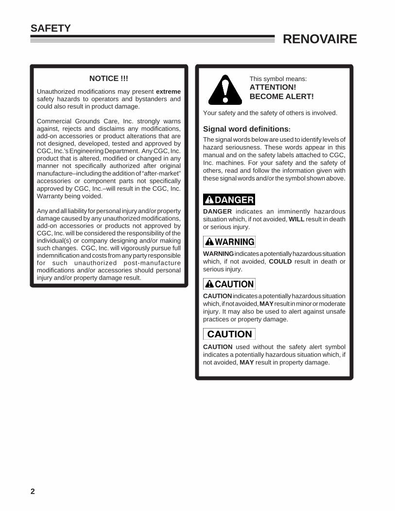
NOTICE !!!
Unauthorized modifications may present extremesafety hazards to operators and bystanders andcould also result in product damage.
Commercial Grounds Care, Inc. strongly warnsagainst, rejects and disclaims any modifications,add-on accessories or product alterations that arenot designed, developed, tested and approved byCGC, Inc.'s Engineering Department. Any CGC, Inc.product that is altered, modified or changed in anymanner not specifically authorized after originalmanufacture–including the addition of “after-market”accessories or component parts not specificallyapproved by CGC, Inc.–will result in the CGC, Inc.Warranty being voided.
Any and all liability for personal injury and/or propertydamage caused by any unauthorized modifications,add-on accessories or products not approved byCGC, Inc. will be considered the responsibility of theindividual(s) or company designing and/or makingsuch changes. CGC, Inc. will vigorously pursue fullindemnification and costs from any party responsiblefor such unauthorized post-manufacturemodifications and/or accessories should personalinjury and/or property damage result.
This symbol means:ATTENTION!BECOME ALERT!
Your safety and the safety of others is involved.
Signal word definitions:
The signal words below are used to identify levels ofhazard seriousness. These words appear in thismanual and on the safety labels attached to CGC,Inc. machines. For your safety and the safety ofothers, read and follow the information given withthese signal words and/or the symbol shown above.
DANGER indicates an imminently hazardoussituation which, if not avoided, WILL result in deathor serious injury.
WARNING indicates a potentially hazardous situationwhich, if not avoided, COULD result in death orserious injury.
CAUTION indicates a potentially hazardous situationwhich, if not avoided, MAY result in minor or moderateinjury. It may also be used to alert against unsafepractices or property damage.
CAUTION used without the safety alert symbolindicates a potentially hazardous situation which, ifnot avoided, MAY result in property damage.

3
RENOVAIREASSEMBLY
GENERAL NOTE: FRONT, REAR, RIGHT HAND AND LEFT HAND REFERENCES BELOWARE WITH RESPECT TO AN OPERATOR AT THE CONTROLS.
SET-UP
1. Set Frame Assembly on blocks so that hitch endof frame is approximately 18" above ground.
To prevent possible injury use an adequate liftingdevice or a minimum of two (2) men when placingmain frame on blocks.
2. Attach transport tires to wheel yokes and inflatetires to 55 p.s.i.
3. Attach cradle assembly to yokes on frame asshown in frame assembly diagram.
4. Attach hydraulic cylinder to lugs on underside offrame and cradle assembly. Make sure end ofcylinder with hose attachment points toward hitchof machine.
5. Assemble aerating wheels as shown in assemblydiagram. Do not mount weight trays at this time.
6. Attach aerating wheel to square bar on mainframe as shown in Figure 1.
NOTE: Attach outside aerating wheel sets as closeto clevis pin as possible and the middle sets as closeto center clevis pin as possible. Center the middleset of each side.
7. Attach aerating tools on aerating wheels.
Tines and slicing knives are sharp. To preventpossible injury use caution when installing theseitems.
8. Attach weight trays as shown in assembly diagram.
9. Remove blocks from beneath main frame.
10. Attach machine to tractor at draw bar and attachhydraulic hose from tractor to cylinder.
11. Lubricate aerating wheels until grease can be seenat wheel bushings.

4
RENOVAIREASSEMBLY
ASSEMBLY
To prevent possible injury use an adequate liftingdevice when placing main frame on blocks.
Use jackstands to provide adequate support. Donot rely on hydraulic or mechanical jacks.
NOTE: Refer to frame assembly parts list on Page17 to assist with assembly.
1. Set the main frame assembly 5 on jackstands.Frame needs to be at least 18" (457 mm) abovethe floor.
2. Install transport wheels 13 to the yokes using (4)1/2-20 X 1-1/2" screws 15 and (4) lockwashers 1.Tighten and check tires for free rotation.
3. Bolt the tongue 12 to the frame 5 using (4)1/2-13 X 2" screws 4, (4) lockwashers 1 and (4)nuts 3. Tighten all four fasteners at this time.
4. Mount the cradle 27 onto the frame 5 using the(3) clevis pins 14. Insert the cradle lugs inbetween the mounting tabs on the frame. SeeFigure 2. Beginning in the middle of the cradle,install a clevis pin and secure with a cotter pin 2.Install and secure the remaining cotter pins.
5. Attach the hydraulic cylinder 24 to the lug on theunderside of the frame using a clevis pin 26.Secure clevis pins with hair pins 25. See notebelow.
NOTE: The hydraulic cylinder has an opening for ahose attacchment. The cylinder must be installedwith this opening positioned toward the front of theunit. See Figure 2.
6. Using the clevis pin 26, attach the other end ofthe cylinder to the lug on the cradle. Secure theclevis with hair pins 25. See Figure 2.
7. Mount the aerating wheel assemblies 27, Figure2 to the tool bar.
NOTE: The aerating wheel assemblies 27 aremounted to the side rails 24, Figure 2 and to theclamps 14, Figure 2.
Beginning in the middle of the frame, clamp awheel assembly onto the tool bar. Keep aminimum gap of 1/8" (3 mm) between the pivotshaft on the clamp and the clevis pin securing thecradle onto the frame. With the wheel assemblyin position, alternate tightening the (2) 1/2-13 X2-1/4" screws 7 and nuts 6, Figure 2 clamping thewheel assembly onto the tool bar. Torque eachscrew to 75 ft-lbss (102 N-m).
8. Attach an aerating wheel assembly 27 toward theoutside of the frame keeping a minimum gap of1/8" (3 mm) between the pivot shaft on the clampand the clevis pin on the cradle. Secureassemblies as stated in Step 7 and repeat themiddle and side assemblies on the other side ofthe frame. Mount the remaining wheelassemblies onto the tool bar, spacing themevenly between the wheel assemblies alreadymounted.
9. Using the 3/8-16 X 1-1/2" bolts 3, Figure 2, mountthe weight tray supports 18 to the side rails of thewheel assemblies. Secure with lockwashers 2and nuts 6. Mount the weight trays onto thesesupports securing each tray with (4) 3/8-16 X 1"screws 5, (4) lockwashers 2 and (4) 3/8-16 nuts6.
10. Mount the desired accessories to the aeratingwheels (tines or blades). For maximumperformance, a double set of tines may bemounted onto the aerating wheels. A longerscrew is needed for this application and can beobtained by ordering Part number 311213 from aservice representative.
11. Lubricate aerating wheels until grease can beseen at the wheel bushings. Check aeratingwheels for free rotation.
12. Remove the jackstands from beneath the mainframe. Hitch the Renovaire to the draw bar onthe tractor and attach the hydraulic hose from thetractor to the hydraulic cylinder.
NOTE: If using the hydraulic hand pump refer to theinstructions for pump installation. The hydraulic handpump is used with the Renovaire when the hydrauliclifting system on the tractor is not used.

5
RENOVAIREHYDRAULIC HAND PUMP
HYDRAULIC HAND PUMP
1. Apply teflon tape to the threads of the hydraulicswivel elbow 12, Figure 3 and install onto thehydraulic cylinder 10. Do not tighten at this time.
2. Mount the hydraulic hand pump 9 onto the pumpplate 8 using (4) 5/16-18 X 1-1/4" screws 4, (4)5/16 lockwashers 3 and (4) 5/16-18 nuts. SeeFigure 3.
3. For ease of operation (left or right hand operator),the hand pump can be installed on eighter side ofthe main frame. Determine which side to mountthe pump and using the (2) U-bolts 14, mount thepump plate 8 onto the frame securing it with 5/16lockwashers and 5/16-18 nuts.
BEFORE INSTALLING THE HYDRAULIC HOSE,REMOVE THE HOSE/CONNECTOR FITTINGFROM THE PUMP AND REMOVE THE PLASTICPLUG.
NOTE: Removal of plastic plug, without removing theconnector from the pump could cause some of theplug to be forced into the pump.
4. Wrap teflon tape around the threads of the hoseconnector fitting and reinstall onto the pump.
5. Teflon tape the connector fittings on the hydraulichose 10 and install the hose onto the pump.Position the hose for installation onto thehydraulic elbow fitting on the cylinder. Make surethe hose does not become kinked or interferewith any moving parts.
6. With the hose properly positioned, adjust theelbow on the cylinder to the approximate positionrequired to connect the hose and elbow fitting.Tighten the elbow into position and tighten thehose onto the elbow. Double check all fittingsand hardware for tightness.
7. Remove the vent-filler plug A and fill the pumpwith one quart(.946L) of type "A" or "F"transmission fluid. DO NOT substitute with anyother type of fluid.
8. Position the pump handle 13 on the top side ofthe tongue, between the hitch and where thetongue mounts to the frame. Place a handle clip7 approximately 2" (51 mm) from each end of thehandle and mark their locations for drilling.
9. Mark and drill a 9/64" (3.6 mm) hole at eachlocation and install the clips using the #10-5/8"self tapping screws 11.

6
RENOVAIRE
546010 - Hydraulic Hand Pump
For use on Renovaire when hydraulic lifting systemon tractor is not used. There are three service kitsavailable for gasket and seal replacement on wornpumps.
548812 - Seal and Gasket Kit
Includes one each of items 1, 4, 5 and 12; two eachof item 2; and three each of item 11. For use onpumps: HP2503-51-00 P148, HP2503-51-00 P348
548831 - Release Valve Replacement Kit
Includes one each of items 6, 7, 8, 9 and 10; andthree each of item 11. For use on all units
548832 - Safety Valve Replacement Kit
Includes one each of item 4; and one assembledsafety valve subassembly (subsitute for item 3).Specify pressure setting required. For use on all units
HYDRAULIC HAND PUMP
7
RENOVAIRETRANSPORTING/OPERATION
TRANSPORTING
This unit is not designed nor meant to be towed at speeds in excess of 10 MPH (16 Km/h).
Towing at excessive speeds will cause damage to frame and/or wheels. This type of damage will notbe repaired under the terms of the warranty.
1. Raise the aerating wheels high enough to hook the eye bolts 11, Figure 1 onto the latch hooks on the sideof the cradle assembly.
2. Lower the aerating wheels until the eye bolts are supporting the cradle assembly.
OPERATION
Before operating, check the area to be aerated and remove any objects which may present a safetyhazard or which may damage the aerator (rocks, cans, etc.).
Do not leave the tractor unattended without first lowering the aerator and stopping the engine.
To prevent possible injury, do not operate aerator without weight trays in place. Do not make anyadjustments or perform any maintenance while tractor is running.
1. Position tractor and equipment where aerating is to begin.
2. Lower aerating wheels and proceed to aerate.
NOTE:Never cross hard surfaces (sidewalks, driveways, stepping stones etc.) with the tines down.
To prevent turf damage, aerator must be raised completely out of the ground while turning the tractor.
Do Not back up when the tines are in the ground or damage to the tines and clamps may occur.
When aerating soft ground and full penetration is not desired, the depth may be controlled by raising thecradle assembly with the hydraulic system.
Failure to lubricate the aerating wheels can cause damage to the axles, bushings and the wheels.

8
RENOVAIRESERVICE
SERVICE
DO NOT use tractor hydraulics to support the aerator while servicing. Hydraulic lines may rupturecausing unit to fall suddenly.
When replacement parts are required, use genuine CGC, Inc. parts or parts with equivalentcharacteristics including type, strength and material. Failure to do so may result in productmalfunction and possible injury to the operator and/or bystanders.
Thoroughly clean all tines inside and out when aerating is completed. A light coat of oil will prevent rust andinsure proper coring and slicing the next time the unit is put into service.
Lubrication
1. Lubricate aerating wheels after every four hours of use. Use a standard lithium based grease.
2. After lubrication of wheels is complete, lubricate the pivot shafts located on the clamps secured to the toolbar.
3. Wipe off lubrication fittings before and after lubrication of aerating wheels.
4. Transport wheel bearings should be repacked yearly using a good grade wheel bearing lubricant.
Transport Wheels
1. Check daily.
2. Repack with grease yearly.
3. Air pressure: MINIMUM 45 p.s.i.MAXIMUM 65 p.s.i.
9
RENOVAIRESERVICE
Axle Replacement
1. Remove the weight tray from the desired aerating wheel assembly. The weight tray supports can remainattached to the side rail.
2. Remove the aerating wheel assembly from the tool bar.
3. Remove one side rail from the wheel assembly and remove the axle. You may need to tap the axle, usinga wood or rubber mallet, to remove it.
4. Install the new axle 19 Figure 2.
5. Attach the side rail onto the wheel assembly and mount the assembly onto the tool bar.
6. Mount the weight tray onto the tray supports.
7. Lubricate the wheel after assembly.
Storage Instructions
1. Thoroughly clean all tines, inside and out, after aerating is completed. A light coat of oil sprayed onto thetines or blades will help prevent rust and ensure proper coring the next time the unit is put into service.
2. Unit should be stored on boards to protect tines or blades from rust and damage. Store in a dry location.
3. Lubrication before long storage periods will help prevent moisture build up in the lubrication cavities.
4. When bringing unit out of storage, check for loose bolts and damaged parts. Tighten and replace asneeded.
5. Check hydraulic cylinder for leaks and replace seal kit if needed. If the cylinder end cap has aRETAINING RING, order item 25. If the cylinder cap has a LOCK WIRE, order item 30.
6. If the unit is equipped with a hydraulic hand pump, check the pump for leaks and proper fluid level. Checkthe hydraulic hose connections for tightness and check the hose for any wear or damage. Refer to theparts list on Page 14 to order replacement seal kits for the pump. The hydraulic hose can be obtained byordering item 10.
7. Proper storage and maintenance will extend the usage and performance of the unit.
10
RENOVAIRESPECIFICATIONS
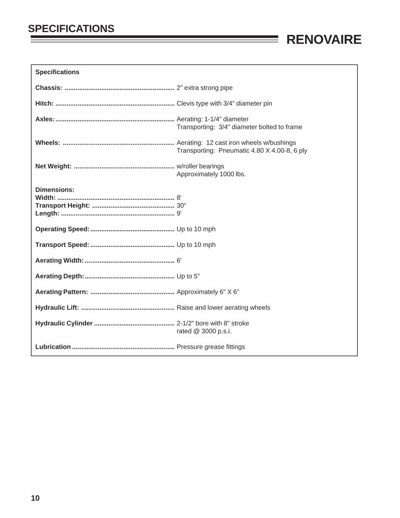
Specifications
Chassis: ............................................................ 2" extra strong pipe
Hitch: ................................................................. Clevis type with 3/4" diameter pin
Axles: ................................................................. Aerating: 1-1/4" diameterTransporting: 3/4" diameter bolted to frame
Wheels: ............................................................. Aerating: 12 cast iron wheels w/bushingsTransporting: Pneumatic 4.80 X 4.00-8, 6 ply
Net Weight: ....................................................... w/roller bearingsApproximately 1000 lbs.
Dimensions:Width: ................................................................ 8'Transport Height: ............................................. 30"Length: .............................................................. 9'
Operating Speed:.............................................. Up to 10 mph
Transport Speed: .............................................. Up to 10 mph
Aerating Width: ................................................. 6'
Aerating Depth: ................................................. Up to 5"
Aerating Pattern: .............................................. Approximately 6" X 6"
Hydraulic Lift: ................................................... Raise and lower aerating wheels
Hydraulic Cylinder ............................................ 2-1/2" bore with 8" strokerated @ 3000 p.s.i.
Lubrication ........................................................ Pressure grease fittings
11
RENOVAIREAERATION TOOLS
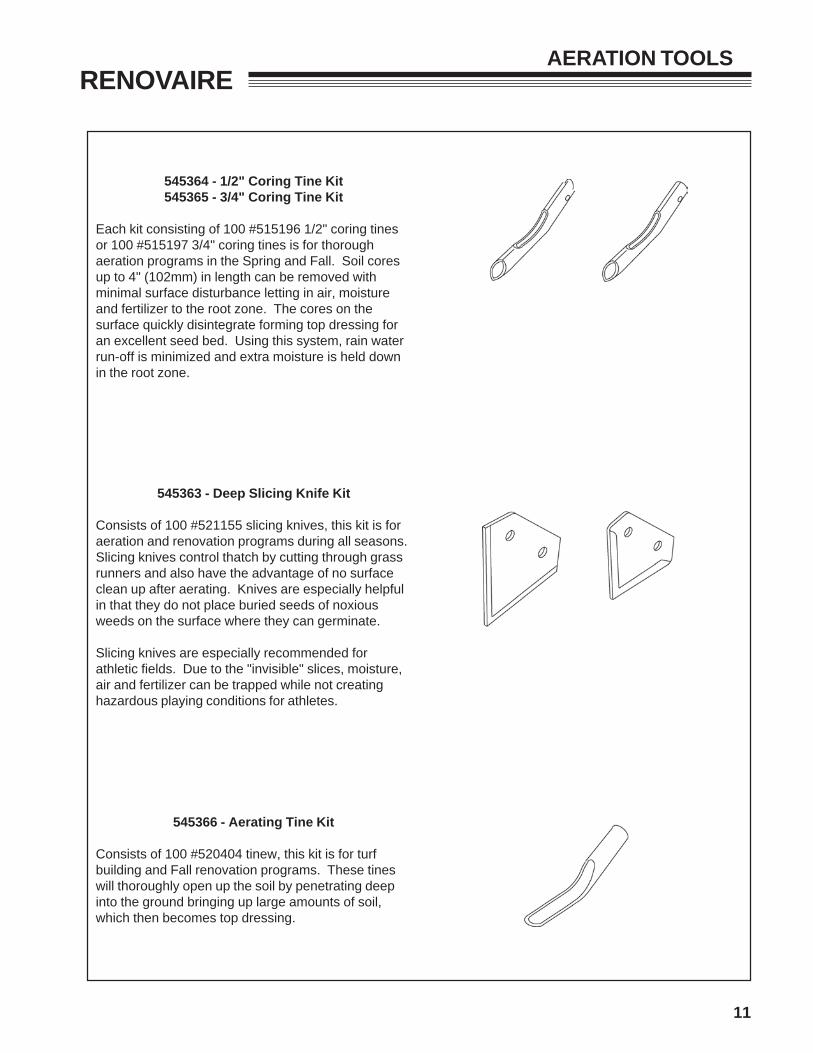
545364 - 1/2" Coring Tine Kit545365 - 3/4" Coring Tine Kit
Each kit consisting of 100 #515196 1/2" coring tinesor 100 #515197 3/4" coring tines is for thoroughaeration programs in the Spring and Fall. Soil coresup to 4" (102mm) in length can be removed withminimal surface disturbance letting in air, moistureand fertilizer to the root zone. The cores on thesurface quickly disintegrate forming top dressing foran excellent seed bed. Using this system, rain waterrun-off is minimized and extra moisture is held downin the root zone.
545363 - Deep Slicing Knife Kit
Consists of 100 #521155 slicing knives, this kit is foraeration and renovation programs during all seasons.Slicing knives control thatch by cutting through grassrunners and also have the advantage of no surfaceclean up after aerating. Knives are especially helpfulin that they do not place buried seeds of noxiousweeds on the surface where they can germinate.
Slicing knives are especially recommended forathletic fields. Due to the "invisible" slices, moisture,air and fertilizer can be trapped while not creatinghazardous playing conditions for athletes.
545366 - Aerating Tine Kit
Consists of 100 #520404 tinew, this kit is for turfbuilding and Fall renovation programs. These tineswill thoroughly open up the soil by penetrating deepinto the ground bringing up large amounts of soil,which then becomes top dressing.
12
RENOVAIREDRAGMAT
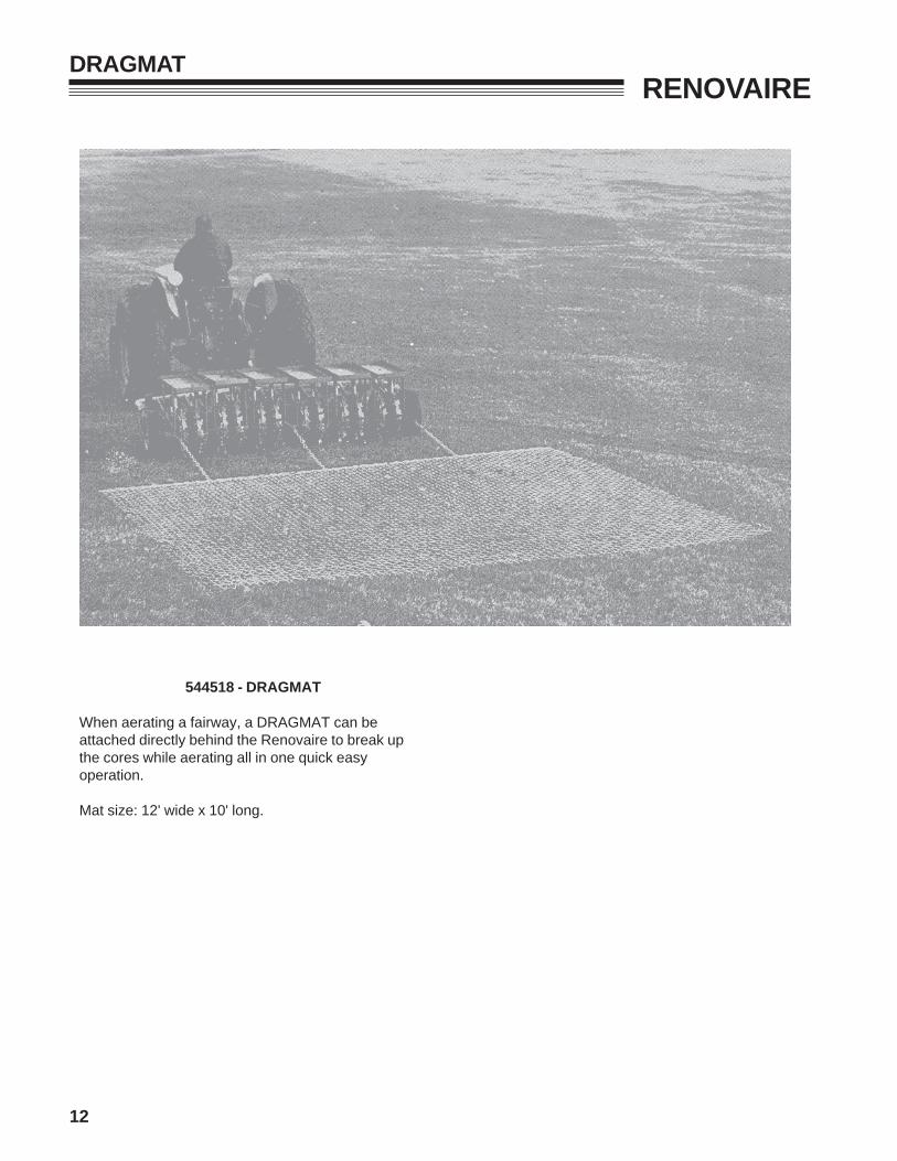
544518 - DRAGMAT
When aerating a fairway, a DRAGMAT can beattached directly behind the Renovaire to break upthe cores while aerating all in one quick easyoperation.
Mat size: 12' wide x 10' long.
13
RENOVAIRE
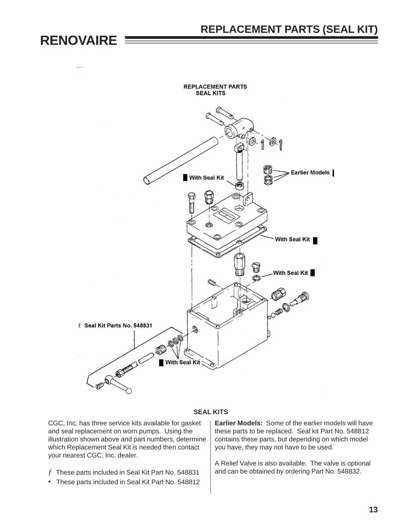
CGC, Inc. has three service kits available for gasketand seal replacement on worn pumps. Using theillustration shown above and part numbers, determinewhich Replacement Seal Kit is needed then contactyour nearest CGC, Inc. dealer.
ƒ These parts included in Seal Kit Part No. 548831• These parts included in Seal Kit Part No. 548812
REPLACEMENT PARTS (SEAL KIT)
SEAL KITS
Earlier Models: Some of the earlier models will havethese parts to be replaced. Seal kit Part No. 548812contains these parts, but depending on which modelyou have, they may not have to be used.
A Relief Valve is also available. The valve is optionaland can be obtained by ordering Part No. 548832.

14
RENOVAIRETORQUE SPECIFICATIONS
15
RENOVAIREPARTS SECTION
PARTSSECTION
16
RENOVAIREFIGURE 1
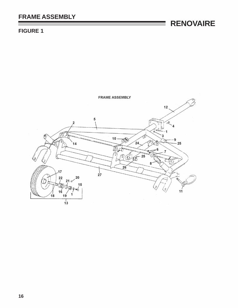
FRAME ASSEMBLY
17
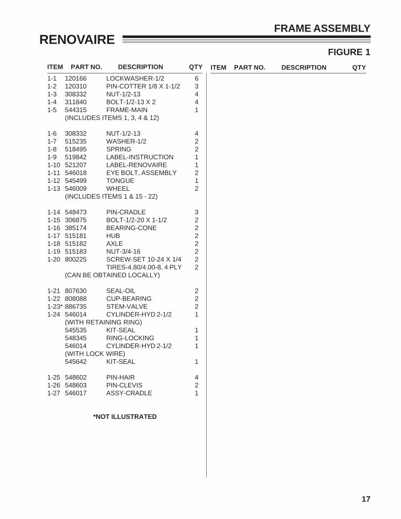
ITEM PART NO. DESCRIPTION QTY ITEM PART NO. DESCRIPTION QTY
RENOVAIREFIGURE 1
FRAME ASSEMBLY
1-1 120166 LOCKWASHER-1/2 61-2 120310 PIN-COTTER 1/8 X 1-1/2 31-3 308332 NUT-1/2-13 41-4 311840 BOLT-1/2-13 X 2 41-5 544315 FRAME-MAIN 1
(INCLUDES ITEMS 1, 3, 4 & 12)
1-6 308332 NUT-1/2-13 41-7 515235 WASHER-1/2 21-8 518495 SPRING 21-9 519842 LABEL-INSTRUCTION 11-10 521207 LABEL-RENOVAIRE 11-11 546018 EYE BOLT, ASSEMBLY 21-12 545499 TONGUE 11-13 546009 WHEEL 2
(INCLUDES ITEMS 1 & 15 - 22)
1-14 548473 PIN-CRADLE 31-15 306875 BOLT-1/2-20 X 1-1/2 21-16 385174 BEARING-CONE 21-17 515181 HUB 21-18 515182 AXLE 21-19 515183 NUT-3/4-16 21-20 800225 SCREW-SET 10-24 X 1/4 2
TIRES-4.80/4.00-8, 4 PLY 2(CAN BE OBTAINED LOCALLY)
1-21 807630 SEAL-OIL 21-22 808088 CUP-BEARING 21-23* 886735 STEM-VALVE 21-24 546014 CYLINDER-HYD 2-1/2 1
(WITH RETAINING RING)545535 KIT-SEAL 1548345 RING-LOCKING 1546014 CYLINDER-HYD 2-1/2 1(WITH LOCK WIRE)545642 KIT-SEAL 1
1-25 548602 PIN-HAIR 41-26 548603 PIN-CLEVIS 21-27 546017 ASSY-CRADLE 1
*NOT ILLUSTRATED
18
RENOVAIREFIGURE 2
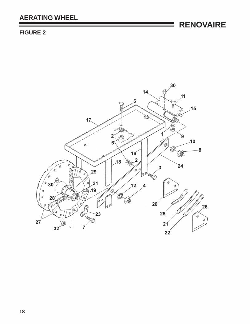
AERATING WHEEL

19
ITEM PART NO. DESCRIPTION QTY ITEM PART NO. DESCRIPTION QTY
RENOVAIREFIGURE 2
AERATING WHEEL
2-1 120166 LOCKWASHER-1/2 122-2 120177 LOCKWASHER-3/8 722-3 302600 BOLT-3/8-16 X 1-1/2 482-4 305134 NUT-HEX, JAM, 7/8-14 122-5 306414 BOLT-3/8-16 X 1 242-6 306562 NUT-3/8-16 722-7 306836 SCREW, HEX 3/8-16X2-1/2 1922-8 307665 NUT, HEX, JAM, 3/4-16 122-9 308332 NUT, HEX, 1/2-13 122-10 309799 WASHER, SHKPRF, 3/4 122-11 316912 SCREW, HEX 1/2-13X2-1/4 122-12 316954 LOCKWASHER-7/8 122-13 515103 SHAFT 62-14 515109 CLAMP 62-15 515115 CAP 62-16 515118 SUPPORT-WEIGHT TRAY 62-17 515119 TRAY-WEIGHT 62-18 515120 SUPPORT-WEIGHT TRAY 62-19 515185 AXLE 62-20 515193 KNIFE-SHALLOW 962-21 515196 TINE, 1/2" CORING 962-22 515197 TINE, 3/4" CORING 962-23 515198 CLAMP-TINE 962-24 515204 RAIL-SIDE 122-25 520404 TINE, AERATING 962-26 521155 KNIFE, DEEP SLICING 962-27 546048 WHEEL 122-28 515184 BUSHING 122-29 521814 SPACER 122-30 548230 FITTING 182-31 548256 SEAL-OIL 242-32 548804 NUT-3/8-16 FLANGELOCK 192
20
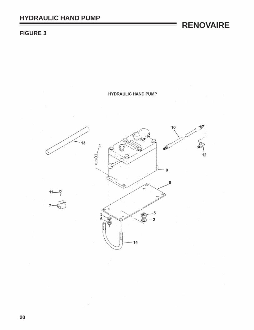
RENOVAIREFIGURE 3
HYDRAULIC HAND PUMP

21
ITEM PART NO. DESCRIPTION QTY ITEM PART NO. DESCRIPTION QTY
RENOVAIREFIGURE 3
HYDRAULIC HAND PUMP
3-1 545370 PUMP KIT, COMP 13-2 120177 LOCKWASHER-3/8 43-3 306325 LOCKWASHER-5/16 43-4 306435 BOLT-5/16-18 X 1-1/4 43-5 306562 NUT-3/8-16 43-6 306932 NUT-5/16-18 43-7 518455 CLIP-HANDLE 23-8 521656 PLATE-PUMP 13-9 546010 HOUSING-PUMP 13-10 546012 HOSE-HYD 20" (508 mm) 13-11 548020 SCREW-#10 X 5/8 SLF TP 23-12 548390 FTG-90 SWIVEL, HYD 13-13 548592 HANDLE 13-14 814494 U-BOLT-3/8-16 2

Equipment from Commercial Grounds Care,Inc. is built to exacting standards ensured byISO 9001 and ISO 14001 registration at all ourmanufacturing locations.
A worldwide dealer network and factory-trainedtechnicians provide reliable, high-qualityproduct support.
ISO
900114001
World Class Quality, Performance And Support
BOB-CAT BUNTON RYAN STEINER