technical manual unit maintenance 5-ton, … · technical manual unit maintenance 5-ton, 6x6, m809...
TRANSCRIPT
ARMY TM 9-2320-260-20AIR FORCE TO 36A12-1C-491
This publication supersedes TM 9-2320-260-20-1,TM 9-2320-260-20-2-1, TM 9-2320-260-20-2-2,TM 9-2320-260-20-3-1, TM 9-2320-260-20-3-2,TM 9-2320-260-20-3-3, and TM 9-2320-260-20-3-4,dated 12 January 1981, for M809 Series Trucks.
T E C H N I C A L M A N U A L
U N I T M A I N T E N A N C E
5 - T O N , 6 X 6 ,
M 8 0 9 S E R I E S T R U C K S
( D I E S E L )
TRUCK, CARGO: 5-TON, 6X6M813 (2320-00-050-8902) (EIC:BSB);
(2320-00-050-8890) (EIC:BSA)M813A1 (2320-00-050-8913) (EIC:BSD);
[2320-00-050-8905) (EIC:BSC)M814 {2320-00-050-8988) (EIC:BSK);
(2320-00-050-8987) (EIC:BSJ)
TRUCK, BOLSTER, LOGGING: 5-TON, 6X6M815 (2320-00-050-8927) (EIC:BSE)
TRUCK, WRECKER, MEDIUM 5-TON, 6X6M816 [2320-00-051-0489) (EIC:BSQ)
TRUCK, DUMP: 5-TON, 6X6M817 (2320-00-050-8970) (EIC:BSF);
(2320-00-051-0589) (EIC:BSR)
TRUCK, TRACTOR 5-TON, 6X6M818 (2320-00-050-8984) (EIC:BSH);
(2320-00-050-8978) (EIC:BSG)
TRUCK, TRACTOR, WRECKER 5-TON, 6X6M819 (2320-00-050-9004) (EIC:BSL)
TRUCK, VAN, EXPANSIBLE: 5-TON, 6X6M820 {2320-00-050-9006) (EIC:BSM)
M820A1 (2320-00-050-9007)M820A2 (2320-00-050-9010) (EIC:BSN)
TRUCK, STAKE, BRIDGE TRANSPORTING: 5-TON, 6X6M821 [2320-00-050-9015) [EIC:BSP) .
D I S T R I B U T I O N S T A T E M E N T A. Approved for public release;
d i s t r i b u t i o n i s u n l i m i t e d .
D E P A R T M E N T S O F T H E A R M Y A N D T H E A I R F O R C E
A P R I L 1 9 9 5
Manual Provided by eMilitary Manuals - http://www.emilitarymanuals.com
TM 9-2320-260-20
WARNING
EXHAUST GASES CAN KILL
1. DO NOT operate your vehicle engine in enclosed area.
2. DO NOT idle vehicle engine with cab windows closed.
3. DO NOT drive vehicle with inspection plates or cover plates removed.
4. BE ALERT at all times for exhaust odors.
5. BE ALERT for exhaust poisoning symptoms. They are:
Headache Dizziness Sleepiness Loss of muscular control
6. If YOU SEE another person with exhaust poisoning symptoms:
Remove person from area Expose to open air Keep person warm Do not permit person to move Administer artificial respiration, if necessary*
For artificial respiration, refer to FM 21-11.
WARNING SUMMARY
Drycleaning solvent is flammable and will not be used near open flame. Use only in well-ventilated places.Failure to do so may result in injury to personnel.
Do not perform battery system checks or inspections near open flame. Injury to personnel may result.
Diesel fuel is highly flammable. Do not perform troubleshooting checks near open flame. Injury topersonnel may result.
Compressed air source will not exceed 30 psi (207 kPa). When cleaning with compressed air, eyeshieldsmust be worn. Failure to wear eyeshields may result in injury to personnel.
Care should be taken when removing surge tank filler cap. Steam or hot coolant under pressure maycause injury to personnel.
Do not perform this procedure while smoking or within 50 feet of sparks or open flame. Fuel is flammableand can explode easily, causing injury or death to personnel and damage to equipment.
Do not use compressed air or dry brush for cleaning when working in areas of vehicle where asbestosbrake lining dust may accumulate. Remove asbestos dust and other residue from these areas using a softbristle brush or cloth soaked with water. Breathing asbestos dust may cause injury to personnel.
Loosen outlet line at air compressor very slowly. Stop procedure and tighten fitting the moment air beginsto escape. Injury to personnel may result if line is accidently disconnected from serviceable operatingcompressor.
Warning a
Manual Provided by eMilitary Manuals - http://www.emilitarymanuals.com

TM 9-2320-260-20
●
●
●
●
●
●
●
●
●
●
●
●
●
●
●
●
●
●
●
●
●
●
●
WARNING SUMMARY (Contd)Do not look into service chamber vent port when performing test. Injury to personnel may result.
Do not disconnect air lines before draining air reservoir. Small parts under pressure may shoot out withhigh velocity, causing injury to personnel.
Do not look into limiting valve vent port when performing test. Injury to personnel may result.
Wear protective mask and work in well-ventilated area when removing glaze from brakeshoes. Asbestosdust may form during glaze removal, causing harm to your health if inhaled.
Loosen supply line at valve very slowly. Stop procedure and tighten fitting of supply line the moment airbegins to escape. Injury to personnel may result if supply line is disconnected from valve.
Loosen delivery line at valve very slowly. Stop procedure and tighten fitting of delivery line the momentair begins to escape. Injury to personnel may result if delivery line is disconnected from valve.
Do not look into parking brake valve vent port when performing test. Injury to personnel may result.
Battery acid (electrolyte) is extremely harmful. Always wear safety goggles and rubber gloves, and donot smoke when performing battery maintenance. Severe injury will result if acid contacts eyes or skin.
Remove all jewelry such as rings, dog tags, bracelets, etc. If jewelry or disconnected battery ground cablecontact battery terminal, a direct short can result, causing instant heating of tools, severe injury topersonnel, or damage to equipment.
When removing battery cables, disconnect ground cable first. Do not allow tools to come in contact withvehicle when disconnecting cable clamps. A direct short can result, causing instant heating of tools, injuryto personnel, tool damage, battery damage, or battery explosion.
Some vehicles have two separate wires and connectors. Mark wires for installation. Connecting wires onwrong terminals may cause fuel to ignite, resulting in injury to personnel.
Do not perform testing near fuel tank with fill cap or sending unit removed. Fuel may ignite, causinginjury to personnel.
Do not drain oil when engine is hot. Injury to personnel may result.
If NBC exposure is suspected, all air filter media should be handled by personnel wearing protectiveequipment. Consult your unit NBC officer or NBC NCO for appropriate handling or disposal instructions.
NBC contaminated filters must be handled using adequate precautions (FM 21-40) and must be disposedof by trained personnel.
Diesel fuel is flammable. Do not perform fuel system procedures near open flame. Injury to personnel mayresult.
Do not touch hot exhaust system components with bare hands. Injury to personnel may result.
Care must be taken while removing surge tank cap when engine temperature is above 175°F (79oC).Escaping steam or hot coolant may cause injury to personnel.
Use caution when testing thermostat. Hot water may cause injury to personnel.
Use care when removing fan blade. Failure to do so may cause injury to personnel.
Eye protection must be worn when removing or installing springs under tension. Failure to do so mayresult in injury to personnel.
Do not smoke, have open flame, or make sparks when performing battery maintenance. Batteries mayexplode, causing severe injury to personnel.
Do not wear jewelry when repairing harnesses. Injury to personnel may result if circuit is suddenlyenergized.
Warning b
Manual Provided by eMilitary Manuals - http://www.emilitarymanuals.com
TM 9-2320-260-20
WARNING SUMMARY (Contd)Brakeshoe springs are under high tension. Use brake spring pliers to replace brakeshoe retractingsprings. Other tools may fail to hold spring, causing injury to personnel.
When removing spring hanger pins, personnel must stand clear of spring ends. Tension may cause springto snap out of hanger, resulting in injury to personnel.
Leaves and plates of assembled spring are under tension. Release tension slowly. Failure to do this mayresult in injury to personnel.
Eye protection is required when using wire brush for cleaning. Failure to do this may result in injury topersonnel.
Use of C-clamps on spring assembly places this unit under tension. Do not complete assembly until centerscrew nut is tightened to specification. Failure to do this may result in injury to personnel.
When removing spring shackle pins, personnel must stand clear of spring ends. Tension may cause springto snap out of shackle, causing injury to personnel.
Ensure vehicle is firmly supported while spring seat is removed. Failure to do so may result in injury topersonnel.
Incorrect brakeshoe installation will prevent automatic adjusters from working. The longer radius end ofbrakeshoe web must ride on the adjustable plunger. Incorrect brakeshoe installation may cause vehiclebrakes to fail, resulting in serious injury or death to personnel.
Do not remove switch before draining air reservoirs. Small parts under pressure may shoot out with highvelocity, causing injury to personnel.
Do not work under vehicle that is supported by jack only. Jack may slip, causing vehicle to fall, and resultin injury or death to personnel.
Never remove tire lockring before deflating tire. Lockring may explode otY, causing injury or death topersonnel.
Lockring must be properly seated around wheel when installed. If lockring is not correctly installed, itmay explode off when tire is inflated, causing injury or death to personnel.
Never attempt to correct seating of lockring by hammering, striking, or forcing while tire is inflated.Lockring may explode off, causing injury or death to personnel.
Never inflate a tire with tire Iockring facing personnel or without a tire inflation cage. Injury or death topersonnel may result from exploding wheel components.
Always use tire inflation equipment specified in TM 9-2610-200-24 and stand 10 ft (3.05 m) away from tireinflation cage while inflating tire. Injury or death may result from exploding wheel components.
Never rest or lean against tire inflation cage while tire is being inflated. Injury or death to personnel mayresult.
Keep fingers clear of hood and cowling when replacing hinge. Failure to do so may result in injury topersonnel.
Support cab body while in raised position for insulator replacement. Failure to do so may result in injuryto personnel.
All personnel must stand clear during lifting operations. A swinging or shifting load may cause injury topersonnel.
Ensure locking handles at forward end of dropsides are engaged before removing tailgate. Failure to do somay cause injury to personnel.
Use eyeshields and gloves when removing and installing door window glass. Glass could shatter, causinginjury to personnel.
Warning c
Manual Provided by eMilitary Manuals - http://www.emilitarymanuals.com
TM 9-2320-260-20
WARNING SUMMARY (Contd)●
●
●
●
●
●
●
●
Support hinged roof panel before removing counterbalance cable. Failure to do so may cause injury topersonnel.
Wear hand protection when handling winch cable. Broken wires may cause injury to personnel.
Never stand between vehicles. Assistant must remain in secondary vehicle to engage service brakes ifcable snaps or automatic brake fails. Failure to do this may result, in injury to personnel.
A minimum of four turns of cable must remain on winch drum at all times. Failure to do this may resultin injury to personnel or damage to equipment.
Always use hand throttle to control engine speed when operating winch. Avoid sudden changes in speed.Rough or jerky operations may cause a shearpin to break or cable to snap. Damage to vehicle or injuryto personnel may result.
Brakeband cover and adjustment screw maybe too hot to proceed with this task. If cover and screw aretoo hot, allow them to cool before continuing with adjustment. Failure to do this may result in injury topersonnel.
Do not remove slave receptacle before disconnecting battery ground cables. If energized battery cablescontact cab, a direct short will result and may cause injury to personnel.
Cleaning solvents are flammable and will not be used near open flame. Use only in well-ventilated places.Failure to do so may result in injury to personnel.
Stay clear of moving parts while engine is running. Failure to do so may result in injury or death topersonnel.
Do not operate a deadline vehicle without preliminary inspection. Failure to do so may cause furtherdamage to a disabled component and possible injury to personnel.
Do not use a dry brush or compressed air to clean brakeshoes. There maybe asbestos dust on brakeshoeswhich can be dangerous to your health if you breathe it. (Brakeshoes must be wet; use a soft bristlebrush. )
Warning d
Manual Provided by eMilitary Manuals - http://www.emilitarymanuals.com

TECHNICAL MANUALNO. 9-2320-260-20
TECHNICAL ORDERNo. 36A12-lC-491
Model
Truck, Cargo
Truck, Bolster, Logging
Truck, Wrecker, Medium
Truck, Dump
Truck, Tractor
Truck, Tractor, Wrecker
Truck, Van, Expansible
ARMY TM 9-2320-260-20AIR FORCE TO 36A12-lC-491
DEPARTMENTS OF THE ARMYAND THE AIR FORCE
WASHINGTON, D.C. 28 April 1995
TECHNICAL MANUALUNIT MAINTENANCE
5-TON, 6X6,
M813M813A1M814
M815
M816
M817
M818
M819
M820M820A1M820A2
Truck, Stake, Bridge Transporting M821
FORM809 SERIES TRUCKS(DIESEL)
NSN Without Winch (EIC)
2320-00-050-8902 (BSB)2320-00-050-8913 (BSD)2320-00-050-8988 (BSK)
2320-00-050-8970 (BSF)
2320-00-050-8984 (BSH)
NSN With Winch (EIC)
2320-00-050-8890 (BSA)2320-00-050-8905 (BSC)2320-00-050-8987 (BSJ)
2320-00-050-8927 (BSE)
2320-00-051-0489 (BSQ)
2320-00-051-0589 (BSR)
2320-00-050-8978 (BSG)
2320-00-050-9004 (BSL)
2320-00-050-9006 (BSM)2320-00-050-90072320-00-050-9010 (BSN)
2320-00-050-9015 (BSP)
This publication supersedes TM 9-2320-260-20-1, TM 9-2320-260-20-2-1, TM 9-2320-260-20-2-2,TM 9-2320-260-20-3-1, TM 9-2320-260-20-3-2, TM 9-2320-260-20-3-3, and TM 9-2320-260-20-3-4,dated 12 January 1981, for M809 Series Trucks.
DISTRIBUTION STATEMENT A. Approved for public release;distribution is unlimited.
i
Manual Provided by eMilitary Manuals - http://www.emilitarymanuals.com

TM 9-2320-260-20
REPORTING OF ERRORSYou can help improve this manual. If you find any mistakes or if you know of away to improve the procedures, please let us know. Mail your letter, DA Form 2028(Recommended Changes to Publications and Blank Forms), or DA Form 2028-2 locatedin back of this manual direct to: Commander, U.S. Army Tank-Automotive Command,ATTN: AMSTA-MB, Warren, Michigan 48397-5000. A reply will be furnished to you.
Page
I HOW TO USE THIS MANUAL . . . . . . . . . . . . . . . . . . . . . . . . . . . . . . . . v
CHAPTER 1
Section I.
II.
III.
CHAPTER 2
Section I.
II.
III.
IV.
V.
VI.
VII.
CHAPTER 3
Section I.
II.
III.
IV.
V.
VI.
VII.
CHAPTER 4
Section I.
II.
III.
IV.
V.
VI.
INTRODUCTION . . . . . . . . . . . . . . . . . . . . . . . . . . . . . . . . . . . . . . . . . 1-1
General Information . . . . . . . . . . . . . . . . . . . . . . . . . . . . . . . . . . . . . . . . . . . 1-1
Equipment Description and Data. . . . . . . . . . . . . . . . . . . . . . . . . . . . . . . . . . 1-3
Principles of Operation . . . . . . . . . . . . . . . . . . . . . . . . . . . . . . . . . . . . . . . . . 1-36
SERVICE AND TROUBLESHOOTING INSTRUCTIONS . . . . . . . . . . . . . 2-1
Repair Parts, Special Tools, TMDE, and Support Equipment . . . . . . . . . . . . . . 2-1
Service Upon Receipt . . . . . . . . . . . . . . . . . . . . . . . . . . . . . . . . . . . . . . . . . . . 2-1
Preventive Maintenance Checks and Services (PMCS) . . . . . . . . . . . . . . . . . . . 2-2
Mechanical Systems Troubleshooting . . . . . . . . . . . . . . . . . . . . . . . . . . . . . . . 2-66
Compressed Air and Air-Hydraulic Brake System Troubleshooting . . . . . . . . . . 2-88
Electrical Systems Troubleshooting . . . . . . . . . . . . . . . . . . . . . . . . . . . . . . . . . 2-96
STE/ICE Troubleshooting(Simplified Test Equipment for Internal Combustion Engines) . . . . . . . . . . . . . 2-186
ENGINE SYSTEMS MAINTENANCE . . . . . . . . . . . . . . . . . . . . . . . . . . 3-1
Engine Lubrication System Maintenance . . . . . . . . . . . . . . . . . . . . . . . . . . . . 3-1
Clutch System Maintenance .
Air Intake System Maintenance
Fuel System Maintenance . .
Accelerator System Maintenance
Exhaust System Maintenance .
Cooling System Maintenance . .
. . . . . . . . . . . . . . . . . . . . . . . . . . . . . . . . . . . 3-16
. . . . . . . . . . . . . . . . . . . . . . . . . . . . . . . . . . . 3-23
. . . . . . . . . . . . . . . . . . . . . . . . . . . . . . . . . 3-32
. . . . . . . . . . . . . . . . . . . . . . . . . . . . . . . . . . 3-68
. . . . . . . . . . . . . . . . . . . . . . . . . . . . . . . . . . . 3-74
. . . . . . . . . . . . . . . . . . . . . . . . . . . . . . . . . . . 3-84
ELECTRICAL SYSTEM MAINTENANCE . . . . . . . . . . . . . . . . . . . . . . . 4-1
Charging System Maintenance.. . . . . . . . . . . . . . . . . . . . . . . . . . . . . . . . . . . 4-1
Starting System Maintenance . . . . . . . . . . . . . . . . . . . . . . . . . . . . . . . . . . . . 4-10
Instruments, Sending Units, Switches, and Horn Maintenance . . . . . . . . . . . . . 4-13
Lighting System Maintenance . . . . . . . . . . . . . . . . . . . . . . . . . . . . . . . . . . . . 4-66
Battery System Maintenance.. . . . . . . . . . . . . . . . . . . . . . . . . . . . . . . . . . . . 4-90
Wiring Circuits and Harness Maintenance . . . . . . . . . . . . . . . . . . . . . . . . . . . 4-106
ii
Manual Provided by eMilitary Manuals - http://www.emilitarymanuals.com
TM 9-2320-260-20
CHAPTER 5
CHAPTER 6
CHAPTER 7
Section I.II.
III.
CHAPTER 8
Section I.II.
III.
CHAPTER 9
Section I.II.
CHAPTER 10
CHAPTER 11
Section I.II.
CHAPTER 12
Section I.II.
III.IV.
V.VI.
VII.
CHAPTER 13
Section I.II.
III.
TRANSMISSION MAINTENANCE . . . . . . . . . . . . . . . . . . . . . . . . . . . . .
TRANSFER CARE SYSTEM MAINTENANCE . . . . . . . . . . . . . . . . . . . . .
PROPELLER SHAFTS, AXLES, AND SUSPENSIONSYSTEM MAINTENANCE . . . . . . . . . . . . . . . .
Propeller Shafts Maintenance . . . . . . . . . . . . . . . . . . . . . . . . . . . . . . . . . . . .Front and Rear Axle Maintenance . . . . . . . . . . . . . . . . . . . . . . . . . . . . . . . . .
Front and Rear Suspension Maintenance . . . . . . . . . . . . . . . . . . . . . . . . . . . .
MECHANICAL PARKING BRAKE, COMPRESSED AIR,AND SERVICE BRAKE SYSTEM MAINTENANCE . . . . . . . . . . . . .
Mechanical Parking Brake Maintenance . . . . . . . . . . . . . . . . . . . . . . . . . . . . .Service Brakes and Hydraulic System Maintenance . . . . . . . . . . . . . . . . . . . . .Compressed Airand Brake System Maintenance . . . . . . . . . . . . . . . . . . . . . . .
WHEELS, HUBS, DRUMS, AND STEERING SYSTEMMAINTENANCE . . . . . . . . . . . . . .
Wheels, Hubs, and Drums Maintenance . . . . . . . . . . . . . . . . . . . . . . . . . . . .Steering System Maintenance . . . . . . . . . . . . . . . . . . . . . . . . . . . . . . . . . . . .
FRAME MAINTENANCE . . . . . . . . . . . . . . . . . . . . . . . . . . . . . . . . . . . .
I BODY, CAB, AND ACCESSORIES MAINTENANCE . . . . . . . . . . . . . . . .
Bodyand Cab Maintenance . . . . . . . . . . . . . . . . . . . . . . . . . . . . . . . . . . . . . .Accessorie sItemsMaintenance . . . . . . . . . . . . . . . . . . . . . . . . . . . . . . . . . . .
SPECIAL PURPOSE BODIES MAINTENANCE . . . . . . . . . . . . . . . . . . . .
Cargo Body Maintenance . . . . . . . . . . . . . . . . . . . . . . . . . . . . . . . . . . . . . . . .Dump Body Maintenance . . . . . . . . . . . . . . . . . . . . . . . . . . . . . . . . . . . . . . . .Van Body Maintenance . . . . . . . . . . . . . . . . . . . . . . . . . . . . . . . . . . . . . . . . .Wrecker Body Maintenance . . . . . . . . . . . . . . . . . . . . . . . . . . . . . . . . . . . . . .Tractor Wrecker Body Maintenance . . . . . . . . . . . . . . . . . . . . . . . . . . . . . . . .Bolster Body Maintenance . . . . . . . . . . . . . . . . . . . . . . . . . . . . . . . . . . . . . . .Tractor Body Maintenance . . . . . . . . . . . . . . . . . . . . . . . . . . . . . . . . . . . . . . .
HOIST, WINCH, CRANE, AND POWER TAKEOFF MAINTENANCE
Hoist and Winch MaintenancePower Divider MaintenancePower Takeoff Maintenance
. . . . . . . . . . . . . . . . . . . . . . . . . . . . . . . . . . . .
. . . . . . . . . . . . . . . . . . . . . . . . . . . . . . . . . . . . .
. . . . . . . . . . . . . . . . . . . . . . . . . . . . . . . . . . . . .
5-1
6-1
7-1
7-17-13
7-27
8-1
8-18-138-38
9-1
9-19-21
10-1
11-1
11-111-67
12-1
12-112-2112-3412-10112-11612-12212-130
13-1
13-113-12313-134
. . .iii
Manual Provided by eMilitary Manuals - http://www.emilitarymanuals.com
TM 9-2320-260-20
CHAPTER 14
Section I.
II.
III.
IV.
V.
VI.
VII.
VIII.
IX.
X.
XI.
CHAPTER 15
Section I.
II.
III.
APPENDIX A
APPENDIX B
APPENDIX C
APPENDIX D
APPENDIX E
INDEX
SPECIAL PURPOSE KITS MAINTENANCE . . . . . . . . . . . . . . . . . . . . . .
Winterization Kits Maintenance. . . . . . . . . . . . . . . . . . . . . . . . . . . . . . . . . . .
Deepwater Fording Kit Maintenance . . . . . . . . . . . . . . . . . . . . . . . . . . . . . . .
A-Frame Kit Maintenance . . . . . . . . . . . . . . . . . . . . . . . . . . . . . . . . . . . . . . .
Mounting Kit Maintenance . . . . . . . . . . . . . . . . . . . . . . . . . . . . . . . . . . . . . .
Mini Lighting Kit Maintenance . . . . . . . . . . . . . . . . . . . . . . . . . . . . . . . . . . .
100-Amp Alternator Kit Maintenance . . . . . . . . . . . . . . . . . . . . . . . . . . . . . . .
Troop Seat and Seatbelt Kits Maintenance . . . . . . . . . . . . . . . . . . . . . . . . . . .
Hand Airbrake Kit Maintenance . . . . . . . . . . . . . . . . . . . . . . . . . . . . . . . . . . .
Tachograph Kit Maintenance . . . . . . . . . . . . . . . . . . . . . . . . . . . . . . . . . . . . .
Convoy Warning Light Kit Maintenance . . . . . . . . . . . . . . . . . . . . . . . . . . . . .
Van Cable Reel Kit Maintenance . . . . . . . . . . . . . . . . . . . . . . . . . . . . . . . . . .
14-1
14-1
14-52
14-58
14-62
14-72
14-78
14-84
14-90
14-92
14-96
14-116
I SHIPMENT AND LIMITED STORAGE . . . . . . . . . . . . . . . . . . . . . . . . . 15-1
General Preparation of Truck for Shipment . . . . . . . . . . . . . . . . . . . . . . . . . . . 15-1
Loading and Movement . . . . . . . . . . . . . . . . . . . . . . . . . . . . . . . . . . . . . . . . . 15-2
Limited Storage . . . . . . . . . . . . . . . . . . . . . . . . . . . . . . . . . . . . . . . . . . . . . . 15-2
REFERENCES . . . . . . . . . . . . . . . . . . . . . . . . . . . . . . . . . . . . . . . . . . . . . .. A-1
MAINTENANCE ALLOCATION CHART . . . . . . . . . . . . . . . . . . . . . . . . . . . . B-1
EXPENDABLE/DURABLE SUPPLIES AND MATERIALS LIST . . . . . . . . . . . C-1
TORQUE LIMITS . . . . . . . . . . . . . . . . . . . . . . . . . . . . . . . . . . . . . . . . . . . .. D-1
SCHEMATIC AND WIRING DIAGRAMS . . . . . . . . . . . . . . . . . . . . . . . . . . . . E-1
. . . . . . . . . . . . . . . . . . . . . . . . . . . . . . . . . . . . . . . . . . . . . . . . . . . . . . . . . Index 1
iv
Manual Provided by eMilitary Manuals - http://www.emilitarymanuals.com

TM 9-2320-260-20
HOW TO USE THIS MANUAL
I ABOUT YOUR MANUAL
Spend some time looking through this manual. You’ll find that it has a new look, different than most ofthe TM’s you’ve been using.
New features added to improve the convenience of this manual and increase your efficiency are:
a.
b.
c.
d.
e.
Accessing Information – These include features such as the bleed-to-edge locators on the cover andedge of the manual. Extensive troubleshooting guides for specific systems lead directly to step-by-stepdirections for problem solving and maintenance tasks.
Illustrations – A variety of methods are used to make locating and fixing components much easier.Locator illustrations with keyed text, exploded views, and cut-away diagrams make the informationin this manual easier to understand and follow.
Modification or Special Purpose Kits – M809 series vehicles can be updated with modificationkits or equipped with special purpose kits. They allow the vehicle to operate more efficiently orperform a special function. Sometimes the vehicle being worked on doesn’t exactly match themaintenance procedure in this manual because the proper kit has not been installed. Refer totroubleshooting sections in chapter 2 to find troubleshooting instructions or a reference to kitinstallation instructions.
Keying Text With Illustrations – Illustration and text are located on facing pages that show thespecific task you are working on. In some cases, the task steps and illustrations are located side byside. Continue reading for an example of modular text and illustrations.
General Features - Your TM is the best source available for providing information and data criticalto vehicle operation and maintenance:
Safety summary (warning pages a, b, C, and d)
General information, equipment description, and data (chapter 1, sections I and II)
Principles of operation (chapter 1, section III)
Preventive Maintenance Checks and Services – PMCS (chapter 2, section III)
Systems Troubleshooting (chapter 2, sections IV, V, VI, and VII)
Detailed maintenance procedures (chapters 3 through 14)
Shipment and limited storage (chapter 15, sections I, II, and III)
References (appendix A)
Maintenance Allocation Chart – MAC (appendix B)
Expendable/durable supplies and materials list (appendix C)
Torque limits (appendix D)
Schematic and Wiring Diagrams (appendix E)
Atypical example of how to use this manual is provided on the following pages.
v
Manual Provided by eMilitary Manuals - http://www.emilitarymanuals.com

TM 9-2320-260-20
I USING YOUR MANUAL: AN EXAMPLE ITASK: The operator of a M809 series vehicle,model number M813A1, has complained of exces-sive exhaust noise and exhaust fumes entering thecab of his vehicle. The vehicle has been assigned toyou for repair.
TROUBLESHOOTING STEPS:
1.
2.
3.
4.
5.
6.
7.
8.
9.
vi
Look at the cover of this manual. You’ll seechapter/section titles listed from top to bottomon the right-hand side.
Look at the right-edge of the manual. Onsome of the pages you’ll see edge indicators(black bars) that are alined with the chapter/section bars on the cover. These are thelocations of the chapters/sections in the text.
Look for “SERVICE AND TROUBLESHOOT-ING INSTRUCTIONS” in the chapter list onthe cover. This is where the troubleshootinginformation is located.
Turn to those pages with the edge indicatormatching the black bar for service andtroubleshooting instructions. Page numbersare also listed next to chapter/section titles.
Chapter 2 is divided into seven sections:●
●
●
●
●
●
●
Section I - Repair Parts, Special Tools,TMDE, and Support Equipment
Section II - Service Upon Receipt
Section III - Preventive MaintenanceChecks and Services (PMCS)
Section IV - Mechanical SystemsTroubleshooting
Section V - Compressed Air andAir-Hydraulic Brake SystemTroubleshooting
Section VI - Electrical SystemsTroubleshooting
Section VII - STE/ICE Troubleshooting
Turn to section IV, “MECHANICALSYSTEMS TROUBLESHOOTING”(page 2-22). This troubleshooting sectionis system-oriented and is broken down into23 major vehicle systems.
One of the first pages of this section is the“MECHANICAL TROUBLESHOOTINGSYMPTOM INDEX” (turn to page 2-23).
Look down the list until you find “EXHAUSTSYSTEM.” Beneath that heading you will findthe symptoms noted by the vehicle operator:“Excessive exhaust noise” and “Exhaustfumes in cab.”
Turn to the page indicated: 2-30.
Manual Provided by eMilitary Manuals - http://www.emilitarymanuals.com

TM 9-2320-260-20
10.
11.
On page 2-30, step/test relating to resolvingthe problem of “Excessive exhaust noise” islisted:
step 1. During your inspection, you discoverthat an exhaust pipe is cracked andrusted. The part must be replaced.Chapter 3, section VI is referenced.
Turn to the ‘TABLE OF CONTENTS” andfind the chapter dealing with the engine. Youfind it as "CHAPTER 3, ENGINE SYSTEMSMAINTENANCE.” Furthermore, you notethat the chapter is divided into sevensections. You are interested in “Section VI.Exhaust System Maintenance.”
NOTE: Before attempting to repair or replace theexhaust system, as a Unit mechanic, you must:
12.
13.
14.
a. Determine the maintenance responsibilityof repair or replacement of the component.
b. If the task is at your echelon of mainte-nance responsibility, you must identifythe tools needed and the replacementparts required.
Refer to the Maintenance Allocation Chart- MAC (appendix B) to determine not onlythe maintenance responsibility of the item,but also to obtain an estimate of the timerequired to perform the task, tools needed,and any special notes/requirements necessary.
Refer to TM 9-2320-260-20P, Unit Mainte-nance Repair Parts and Special Tools List forM809 Series Vehicles, for requisition dataconcerning replacement parts for this task.
Turn to chapter 3, section VI, which covers"EXHAUST SYSTEM MAINTENANCE.”In the maintenance index we find that thereare four paragraphs listed.
Paragraph 3-41 is a task for replacing theexhaust system used only on model M821vehicles. All other M809 series vehicles willfollow para. 3-40 for replacement of theexhaust system. Notice that, in this case,it starts on page 3-76.
The first two pages shown have proceduresand illustrations for performing the removalsteps for components of the exhaust system.
vii
Manual Provided by eMilitary Manuals - http://www.emilitarymanuals.com

TM 9-2320-260-20
DETAILED MAINTENANCE PROCEDURES:
15. Detailed procedures: Include everything you must do to accomplish a basic maintenance task.
a. Before beginning the maintenance task, look through the procedure. You must familiarize yourselfwith the entire maintenance procedure before beginning the maintenance task. The entire proce-dure of paragraph 3-40: “VERTICAL EXHAUST PIPE MAINTENANCE” includes: a. Removaland b. Installation.
b. The eight basic headings listed under “INITIAL SETUP” outline special tools, materials, personnelrequirements, and special conditions. Headings will not be listed if there are no entries. Theheadings are:
APPLICABLE MODELS Any models that require that particular maintenance task.
TEST EQUIPMENT Test equipment needed to complete a task.
SPECIAL TOOLS Those special tools needed to complete a task. Common tools are not listed.
MATERIALS/PARTS All parts or materials needed to complete a task.
PERSONNEL REQUIRED The number of personnel needed to perform a task. If only onemechanic is needed, this heading will not be used. If you think that you need more help tocorrectly or safely complete a task (perhaps as the result of unusual conditions, etc.), alertyour supervisor and ask for help.
REFERENCES (TM) Those additional manuals needed to complete a task.
EQUIPMENT CONDITION Notes the conditions that must exist before starting the task. Forexhaust system replacement, the vehicle must have the parking brake set and the air cleanerelement removed.
GENERAL SAFETY INSTRUCTIONS Summarizes all safety warnings for the maintenance task.
c. A step-by-step maintenance procedure follows the “INITIAL SETUP” and gives detailed instructions
16.
17.
18.
19.
20.
for the procedure. These instructions give part name and action performed. The numbers in paren-theses correspond to the part’s callout number in the accompanying illustration. Warnings, cautions,and notes give additional information.
● WARNINGS – Indicate conditions, practices, or procedures which must be observed to avoidpersonnel injury, loss of life, or long-term health hazard.
● CAUTIONS – Indicate conditions, practices, or procedures which must be observed to avoiddamage to equipment or destruction of equipment.
● NOTES – Include essential information of special importance, interest, or aid in jobperformance.
d. At the end of a procedure, “FOLLOW-ON TASKS” will list those additional tasks that must beperformed to complete the procedure.
You can also use the Table of Contents (page ii) to find more information about the vehicle. Forexample: Principles of Operation in chapter 1.
Unit PMCS are presented in table 2-1 starting on page 2-4.
Chapter 2, section VII, STE/ICE Troubleshooting, can be used if STE/ICE is available fortroubleshooting or PMCS.
Refer to TM 9-2320-260-20P, Unit Maintenance Repair Parts and Special Tools List for Truck, 5-Ton,6x6, M809 Series, when requisitioning parts, special tools, and equipment for unit maintenance.
Your manual is easier to use once you understand its design. We hope it will encourage you to use itmore often as an aid to maintenance support for M809 series vehicles.
viii
Manual Provided by eMilitary Manuals - http://www.emilitarymanuals.com

TM 9-2320-260-20
CHAPTER 1INTRODUCTION
Section I. General Information (page 1-1)Section II. Equipment Description and Data (page 1-3)Section III. Principles of Operation (page 1-36)
Section I. GENERAL INFORMATION
1-1. SCOPE a. This technical manual contains information for unit maintenance of 5-ton, 6x6, M809 series vehicles.b. Vehicle model numbers and equipment names covered are:
M813 Cargo Truck, W/W and WO/WM813A1 Cargo Truck, W/W and WO/W (Dropside)M814 Cargo Truck, W/W and WO/W (XLWB)M815 Bolster Logging Truck, W/WM816 Medium Wrecker Truck, W/WM817 Dump Truck, W/W and WO/WM818 Tractor Truck, W/W and WO/WM819 Wrecker Tractor Truck, W/WM820 and M820A1 Expansible Van Truck, WO/WM820A2 Expansible Van Truck, WO/W (W/HLG)M821 Bridge Transporting Stake Truck, WO/W
c. The 5-ton, 6x6, M809 series trucks are designed for transporting and retrieving materials andpersonnel.
I 1-2. MAINTENANCE FORMS, RECORDS, AND REPORTS
Department of the Army forms and procedures used for equipment maintenance will be those prescribedby DA Pam 738-750, The Army Maintenance Management System (TAMMS).
1-3. DESTRUCTION OF ARMY MATERIEL TO PREVENT ENEMY USE
Procedures for destruction of Army equipment to prevent enemy use can be found in TM 750-244-6.
1-4. PREPARATION FOR STORAGE OR SHIPMENT IStorage and limited storage instructions are in chapter 15 of this manual. Additional information can
be found in TM 746-10, Marking, Packing and Shipment of Supplies and Equipment General PackagingInstructions for Field Use.
I 1-5. REPORTING EQUIPMENT IMPROVEMENT RECOMMENDATIONS (EIR’s)
If the design of your vehicle needs improvement, let us know. If your vehicle is in proper operatingcondition and there are problems with vehicle or equipment performance, send us an EIR. You, the user, arethe only one who can tell us what you don’t like about your equipment. It is not necessary to show a newdesign or a better way to perform a procedure. Just let us know why you don’t like the design orperformance. Put it on an SF 368 (Quality Deficiency Report). Mail it to us at Commander, U.S. ArmyTank-Automotive and Armaments Command, ATTN: AMSTA-IM-MMAA Warren, Michigan 48397-5000.We’ll send you a reply.
1-1
Manual Provided by eMilitary Manuals - http://www.emilitarymanuals.com
TM 9-2320-260-20
I 1-6. EQUIPMENT IMPROVEMENT REPORT AND MAINTENANCE DIGEST (EIR MD)
The quarterly Equipment Improvement Report and Maintenance Digest, TB 43-0001-39 series, containsvaluable field information on the equipment covered in this manual. The information in the TB 43-0001-39series is compiled from some of the Equipment Improvement Reports that you prepared on the vehicles covered in this manual. Many of these articles resulted from comments, minor alterations, proposedModification Work Orders (MWO’s), actions taken on some of your DA form 2028’s (Recommended Changesto Publications), and advance information on proposed changes that may affect this manual. The informa-tion will help you in doing your job better and will help in keeping you advised of the latest changes tothis manual.
1-7. WARRANTY INFORMATION
The 5-ton, 6x6, M809 series Cummins diesel engine (model NHC-250), and Dana transmission (model6453) are warranted in accordance with TB 9-2320-295-15/21. The warranty starts on the date, found inblock 23, DA Form 2408-9, in the logbook. Report all defects in material or workmanship to your supervisor,who will take appropriate action.
1-2
Manual Provided by eMilitary Manuals - http://www.emilitarymanuals.com
TM 9-2320-260-20
Section II. EQUIPMENT DESCRIPTION AND DATA
1-8. GENERAL
The 5-ton, 6x6, M809 series trucks are tactical vehicles designed for use over all types of roads and cross-country terrain, in extreme high or low temperatures and humidity. All vehicles in this series are poweredby a 240 horsepower Cummins, NHC-250 series diesel engine. A five-speed manual transmission and two-speed transfer case provide ten overall speed ranges. The trucks are capable of fording hard-bottom watercrossings up to 30 inches (76.2 centimeters) without a deepwater fording kit, and 78 inches (198. 1 centi-meters) with the kit All trucks are also equipped with a rear pintle hook for towing operations. Two frontshackles and a pin on top of the rear springs provide a ready means of lifting the truck for transportation.
1-9. EQUIPMENT DESCRIPTION AND DATA INDEX
PARA.NO. TITLE PAGE
NO.
1-10. Equipment Characteristics, Capabilities, and Features 1-41-11. Location and Description of Major External Components 1-101-12. Location and Description of Major Internal Components 1-121-13. Location and Contents of Warning, Caution, and Data Plates 1-141-14. Differences Between Models 1-321-15. Vehicle Performance Data 1-33
1-3
Manual Provided by eMilitary Manuals - http://www.emilitarymanuals.com
TM 9-2320-260-20
1-10. EQUIPMENT CHARACTERISTICS, CAPABILITIES, AND FEATURES
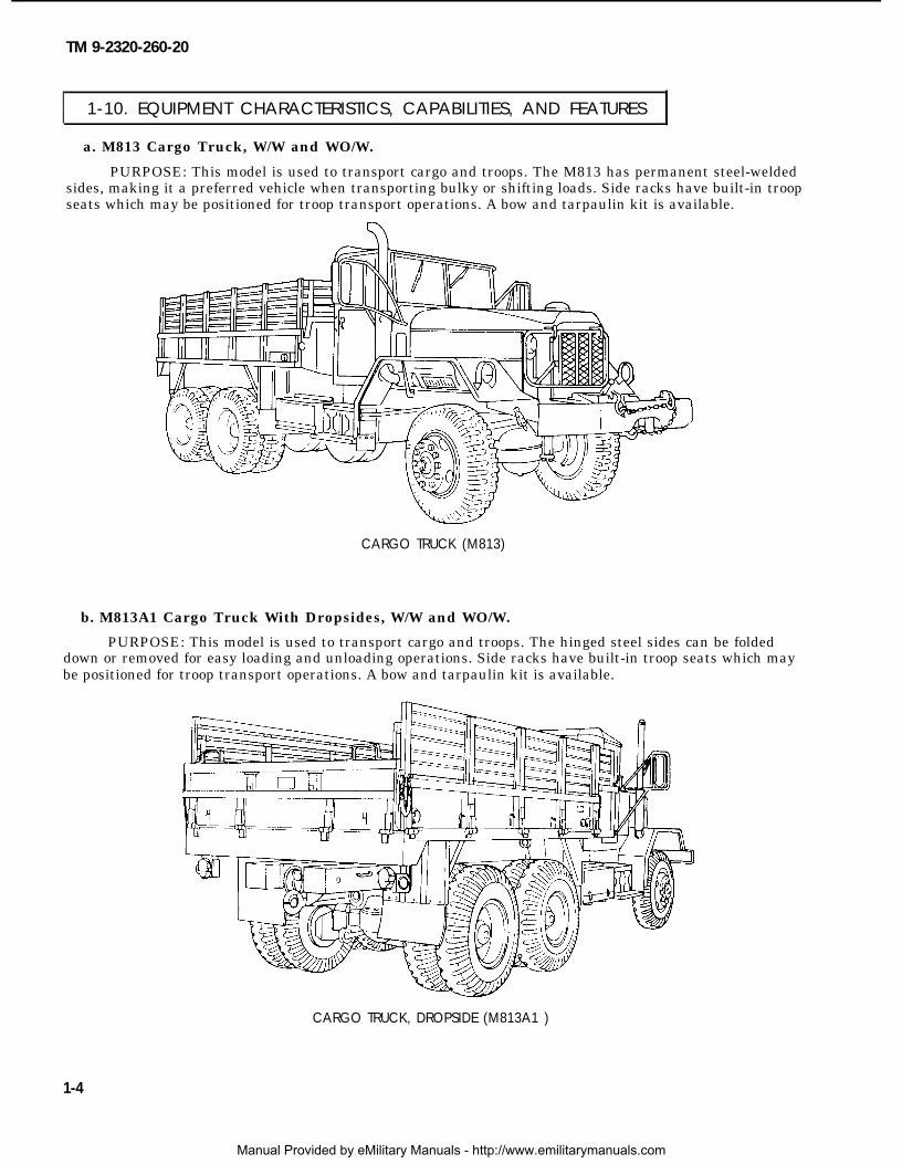
a. M813 Cargo Truck, W/W and WO/W.
PURPOSE: This model is used to transport cargo and troops. The M813 has permanent steel-weldedsides, making it a preferred vehicle when transporting bulky or shifting loads. Side racks have built-in troopseats which may be positioned for troop transport operations. A bow and tarpaulin kit is available.
CARGO TRUCK (M813)
b. M813A1 Cargo Truck With Dropsides, W/W and WO/W.
PURPOSE: This model is used to transport cargo and troops. The hinged steel sides can be foldeddown or removed for easy loading and unloading operations. Side racks have built-in troop seats which maybe positioned for troop transport operations. A bow and tarpaulin kit is available.
CARGO TRUCK, DROPSIDE (M813A1 )
1-4
Manual Provided by eMilitary Manuals - http://www.emilitarymanuals.com
TM 9-2320-260-20
1-10. EQUIPMENT CHARACTERISTICS, CAPABILITIES, AND FEATURES (Contd)
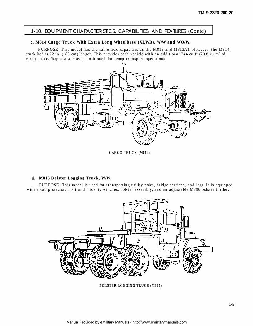
c. M814 Cargo Truck With Extra Long Wheelbase (XLWB), W/W and WO/W.PURPOSE: This model has the same load capacities as the M813 and M813A1. However, the M814
truck bed is 72 in. (183 cm) longer. This provides each vehicle with an additional 744 cu ft (20.8 cu m) ofcargo space. ‘hop seata maybe positioned for troop transport operations.
d.
CARGO TRUCK (M814)
M815 Bolster Logging Truck, W/W.
PURPOSE: This model is used for transporting utility poles, bridge sections, and logs. It is equippedwith a cab protector, front and midship winches, bolster assembly, and an adjustable M796 bolster trailer.
BOLSTER LOGGING TRUCK (M815)
1-5
Manual Provided by eMilitary Manuals - http://www.emilitarymanuals.com

TM 9-2320-260-20
1-10. EQUIPMENT CHARACTERISTICS, CAPABILITIES, AND FEATURES (Contd)
e. M816 Medium Wrecker Truck, W/W.
PURPOSE: This model is used for wrecker and salvage operations and has a revolving hydrauliccrane with a self-supporting boom that can extend from 10-18 ft (3.05-5.49 m). Boom-to-ground supportsare provided. Crane lifting capacity is 20,000 lb (9,080 kg). The vehicle is also equipped with a front winch[20,000 lb (9,080 kg) capacity] and rear winch [45,000 lb (20,430 kg) capacity] for freeing the vehicle whenit becomes mired.
MEDIUM WRECKER TRUCK (M816)
f. M817 Dump Truck, W/W and WO/W.
PURPOSE: This model is used for hauling and dumping cargo. The body has provisions for installingside rack, troop seat, bow, and canvas kits for troop transport. It can haul up to 10,000 lb (4,540 kg) and towup to 15,000 lb (6,810 kg) when fully loaded. The front end of the welded steel body extends up and over thevehicle cab to protect it from damage during loading operations.
DUMP TRUCK (M817)
1-6
Manual Provided by eMilitary Manuals - http://www.emilitarymanuals.com
TM 9-2320-260-20
1-10. EQUIPMENT CHARACTERISTICS, CAPABILITIES, AND FEATURES (Contd) I
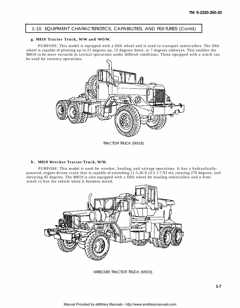
g. M818 Tractor Truck, W/W and WO/W.
PURPOSE: This model is equipped with a fifth wheel and is used to transport semitrailers. The fifthwheel is capable of pivoting up to 21 degrees up, 15 degrees down, or 7 degrees sideways. This enables theM818 to be more versatile in tactical operations under difficult conditions. Those equipped with a winch canbe used for recovery operations.
h.
TRACTOR TRUCK (M818)
M819 Wrecker Tractor Truck, W/W.
PURPOSE: This model is used for wrecker, hauling, and salvage operations. It has a hydraulically-powered, engine-driven crane that is capable of extending 11.5-26 ft (3.5 1-7.93 m), rotating 270 degrees, andelevating 45 degrees. The M819 is also equipped with a fifth wheel for hauling semitrailers and a frontwinch to free the vehicle when it becomes mired.
WRECKER TRACTOR TRUCK (M819)
1-7
Manual Provided by eMilitary Manuals - http://www.emilitarymanuals.com

TM 9-2320-260-20
1-10. EQUIPMENT CHARACTERISTICS, CAPABILITIES, AND FEATURES (Contd)
i. M820, M820A1, and M820A2 Expansible Van Truck, WO/W.
PURPOSE: These models are used for electrical, maintenance, supply, power, and base station
operations. The M820A2 has a hydraulic liftgate [3,000 lb (1,362 kg) capacity], which makes it the preferredvehicle to use when heavy, delicate electronic equipment has to be moved in or out of the van.
EXPANSIBLE VAN TRUCK (M820)
EXPANSIBLE VAN TRUCK (M820A1)
1-8
Manual Provided by eMilitary Manuals - http://www.emilitarymanuals.com
TM 9-2320-260-20
1-10. EQUIPMENT CHARACTERISTICS, CAPABILITIES, AND FEATURES (Contd)
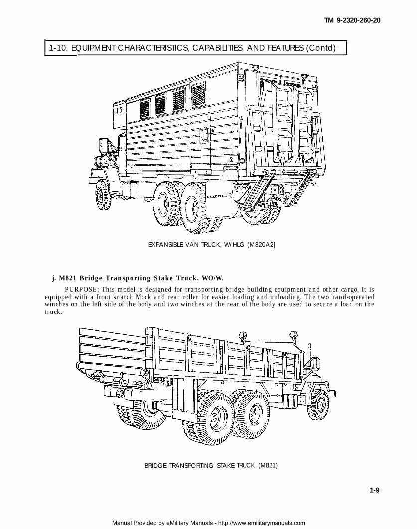
EXPANSIBLE VAN TRUCK, W/HLG (M820A2]
j. M821 Bridge Transporting Stake Truck, WO/W.
PURPOSE: This model is designed for transporting bridge building equipment and other cargo. It isequipped with a front snatch Mock and rear roller for easier loading and unloading. The two hand-operatedwinches on the left side of the body and two winches at the rear of the body are used to secure a load on thetruck.
BRIDGE TRANSPORTING STAKE TRUCK (M821)
1-9
Manual Provided by eMilitary Manuals - http://www.emilitarymanuals.com
TM 9-2320-260-20
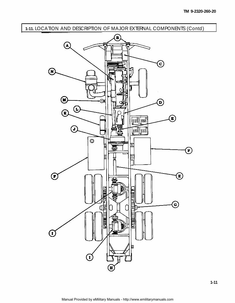
1-11. LOCATION AND DESCRIPTION OF MAJOR EXTERNAL COMPONENTS
The external components described below are common to most of the vehicles covered in this manual.Special differences can be found in TM 9-2320-260-10 or table 1-1, Differences Between Models, in this manual.
A ENGINE – Provides power for the vehicle.
B
C
D
E
F
G
H
I
J
K
L
M
N
1-10
LIFTING/TIEDOWN SHACKLES – Used for lifting the vehicle during ship-to-shore operations andfor tiedown attachments when transporting vehicle.
FRONT WINCH – Powered by a propeller shaft extending from transmission power takeoff to permitrecovery operations.
TRANSMISSION – Manual transmission that transmits engine power to transfer case.
REAR PROPELLER SHAFT(S) – Transmits engine power from transmission to transfer case andthen to rear differentials.
FUEL TANK(S) – Stores fuel.
REAR BOGIE – Suspension system that supports rear vehicle weight.
TOWING PINTLE HOOK – Permits towing of vehicles, trailers, and other equipment.
REAR DIFFERENTIALS – Transmit power from propeller shafts through axles to wheels.
TRANSFER CASE – The two-speed transfer case, along with five forward speed transmission,provides 10 speed ranges to front and rear differentials.
AIR RESERVOIRS – Two storage tanks for compressed air.
FRONT PROPELLER SHAFT – Transmits engine power from transfer case to front differential.
FUEL FILTER AND WATER SEPARATOR – Filters contaminants from fuel.
AIR CLEANER – Filters air before it enters the intake manifold.
Manual Provided by eMilitary Manuals - http://www.emilitarymanuals.com
TM 9-2320-260-20
1-11. LOCATION AND DESCRIPTION OF MAJOR EXTERNAL COMPONENTS (Contd) I
1-11
Manual Provided by eMilitary Manuals - http://www.emilitarymanuals.com

TM 9-2320-260-20
1-12. LOCATION AND DESCRIPTION OF MAJOR INTERNAL COMPONENTS
The internal components described below are common to most of the vehicles covered in this manual.Components not covered here are found in TM 9-2320-260-10 or the applicable maintenance chapters ofthis manual.
A STEERING WHEEL - Used to manually control vehicle.
B
C
D
E
F
G
H
I
J
K
L
M
TRANSMISSION GEARSHIFT LEVER - Used to place transmission in 1 through 5 forward drivepositions, reverse, or neutral.
FRONT WINCH CONTROL LEVER - A two-position lever to engage or disengage drive to frontwinch.
TRANSFER CASE SHIFT LEVER - Used on all vehicles to change ratio of driving power to axlesand wheels. Lever is pulled up for HIGH range (greater speed and lower power) or pushed down forLOW range (lower speed and higher power).
DRIVER’S SEAT - One crewmember, flotation, or fixed, adjustable.
POWER DIVIDER CONTROL LEVER LOCK (M816) - Prevents power divider control lever frombeing placed in engaged position.
POWER DIVIDER CONTROL LEVER (M816) - Used to power hydraulic crane, dump bodyhydraulics, and rear winch.
PARKING BRAKE CONTROL LEVER - Pulled up to apply parking brake. The knob at the topof the handle is turned clockwise to increase brake cable tension.
HEADLIGHT BEAM SELECTOR SWITCH - Depressed to select HIGH or LOW headlight beam.
ACCELERATOR PEDAL - Used to control engine speed.
CLUTCH PEDAL - Depressed to disengage engine from transmission and allows shifting to adifferent gear ratio.
BRAKE PEDAL - Depressed to slow or stop vehicle.
INSTRUMENT PANEL – Contains indicators, gages, and various switches used to monitor engineperformance and activate accessory components of the vehicle.
1-12
Manual Provided by eMilitary Manuals - http://www.emilitarymanuals.com