technical note template - william j. hughes technical … · performance assessment of the laufer...
TRANSCRIPT

Performance Assessment of the Laufer Wind Aircraft Detection System as an Aircraft Detection Lighting System James Patterson, Jr. October 2015 DOT/FAA/TC-TN15/54 This document is available to the U.S. public through the National Technical Information Services (NTIS), Springfield, Virginia 22161. This document is also available from the Federal Aviation Administration William J. Hughes Technical Center at actlibrary.tc.faa.gov.
U.S. Department of Transportation Federal Aviation Administration
ote
tech
nica
l no
te t
ech

NOTICE
This document is disseminated under the sponsorship of the U.S. Department of Transportation in the interest of information exchange. The United States Government assumes no liability for the contents or use thereof. The United States Government does not endorse products or manufacturers. Trade or manufacturer's names appear herein solely because they are considered essential to the objective of this report. The findings and conclusions in this report are those of the author(s) and do not necessarily represent the views of the funding agency. This document does not constitute FAA policy. Consult the FAA sponsoring organization listed on the Technical Documentation page as to its use. This report is available at the Federal Aviation Administration William J. Hughes Technical Center’s Full-Text Technical Reports page: actlibrary.tc.faa.gov in Adobe Acrobat portable document format (PDF).
Technical Documentation Page 1. Report No.
DOT/FAA/TC-TN15/54 2. Government Accession No. 3. Recipient's Catalog No.
4. Title and Subtitle PERFORMANCE ASSESSMENT OF THE LAUFER WIND AIRCRAFT DETECTION SYSTEM AS AN AIRCRAFT DETECTION LIGHTING SYSTEM
5. Report Date October 2015
6. Performing Organization Code ANG-E261
7. Author(s) James Patterson, Jr.
8. Performing Organization Report No.
9. Performing Organization Name and Address 10. Work Unit No. (TRAIS) Federal Aviation Administration William J. Hughes Technical Center Aviation Research Division Airport Technology R&D Section Atlantic City International Airport, NJ 08405
11. Contract or Grant No.
12. Sponsoring Agency Name and Address U.S. Department of Transportation Federal Aviation Administration Airport Engineering Division 800 Independence Ave. SW Washington, DC 20591
13. Type of Report and Period Covered Technical Note
14. Sponsoring Agency Code AAS-100
15. Supplementary Notes 16. Abstract The Federal Aviation Administration (FAA) Airport Safety Research and Development (R&D) Section conducted a performance assessment of the Laufer Wind Aircraft Detection System (ADS). The purpose of this assessment was to determine if the Laufer Wind ADS meets the aircraft detection lighting system (ADLS) requirements specified in Chapter 14 of FAA Advisory Circular (AC) 70/7460-1L, “Obstruction Marking and Lighting.” The Airport Safety R&D Section evaluated the Laufer Wind ADS at the U.S. Department of Energy, National Renewal Energy Laboratory, National Wind Technology Center near Boulder, Colorado. The performance assessment, consisting of demonstrations, flight tests, and data analysis, began in June 2014 and concluded in November 2014. In this performance assessment, a series of flight patterns were flown against the Laufer Wind ADS to demonstrate whether it could meet the FAA performance requirements specified in AC 70/7460-1L. The Laufer Wind ADS performed according to the manufacturer’s specifications and met the performance requirements identified in AC 70/7460-1L. In addition, the data collected during the performance assessment confirmed that the performance requirements specified in AC 70/7460-1L remain valid and provide for a technology that offers a satisfactory level of safety for the flying public. At the same time, this technology reduces the impact of obstruction lights on nearby communities and migratory bird populations. 17. Key Words
Aircraft detection lighting system, Obstruction light, Obstruction lighting, L-864, Laufer Wind
18. Distribution Statement
This document is available to the U.S. public through the National Technical Information Service (NTIS), Springfield, Virginia 22161. This document is also available from the Federal Aviation Administration William J. Hughes Technical Center at actlibrary.tc.faa.gov.
19. Security Classif. (of this report) Unclassified
20. Security Classif. (of this page) Unclassified
21. No. of Pages 45
22. Price
Form DOT F 1700.7 (8-72) Reproduction of completed page authorized.

iii
TABLE OF CONTENTS
Page EXECUTIVE SUMMARY ix
INTRODUCTION 1
Purpose 1 Background 1 Objectives 2 Related Documentation 3
AIRCRAFT DETECTION LIGHTING SYSTEM STANDARDS 4
LAUFER WIND ADS CHARACTERISTICS AND SPECIFICATIONS 6
Laufer Wind ADS Operational Description 6 Laufer Wind ADS Radar Description 7 Obstruction Light Controller Unit Description 8 Central Controller Description 9 Counting Aircraft Ingress and Egress 9 Laufer Wind ADS Perimeters 10 Laufer Wind ADS Fail-Safe Design 11
LAUFER WIND ADS INSTALLATION DESCRIPTION AT THE NWTC 12
Laufer Wind ADS Radar Coverage at NWTC 14 THE FAA TESTS OF THE LAUFER WIND ADS AT THE NWTC 16
The FAA Flight Evaluation 16 The FAA Component Failure Evaluation 17
RESULTS 18
Basic Function Evaluation 18 Detection Performance Evaluation 19 Component Failure Evaluation 29 Laufer Wind ADS Operational Experience 30

iv
CONCLUSIONS 31
REFERENCES 31
APPENDICES
A—Advisory Circular 70/7460-1L, Chapter 14, Aircraft Detection Lighting Systems B—Laufer Wind Aircraft Detection System Information
v
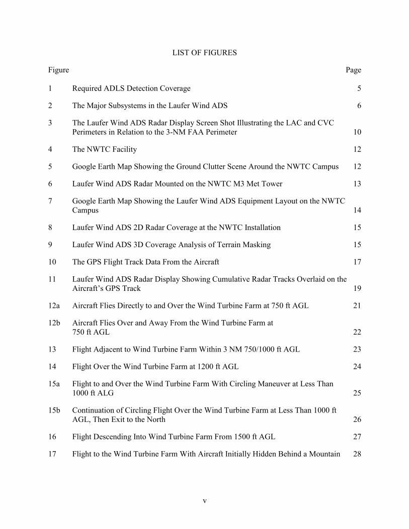
LIST OF FIGURES
Figure Page 1 Required ADLS Detection Coverage 5
2 The Major Subsystems in the Laufer Wind ADS 6
3 The Laufer Wind ADS Radar Display Screen Shot Illustrating the LAC and CVC Perimeters in Relation to the 3-NM FAA Perimeter 10
4 The NWTC Facility 12
5 Google Earth Map Showing the Ground Clutter Scene Around the NWTC Campus 12
6 Laufer Wind ADS Radar Mounted on the NWTC M3 Met Tower 13
7 Google Earth Map Showing the Laufer Wind ADS Equipment Layout on the NWTC Campus 14
8 Laufer Wind ADS 2D Radar Coverage at the NWTC Installation 15
9 Laufer Wind ADS 3D Coverage Analysis of Terrain Masking 15
10 The GPS Flight Track Data From the Aircraft 17
11 Laufer Wind ADS Radar Display Showing Cumulative Radar Tracks Overlaid on the Aircraft’s GPS Track 19
12a Aircraft Flies Directly to and Over the Wind Turbine Farm at 750 ft AGL 21
12b Aircraft Flies Over and Away From the Wind Turbine Farm at 750 ft AGL 22
13 Flight Adjacent to Wind Turbine Farm Within 3 NM 750/1000 ft AGL 23
14 Flight Over the Wind Turbine Farm at 1200 ft AGL 24
15a Flight to and Over the Wind Turbine Farm With Circling Maneuver at Less Than 1000 ft ALG 25
15b Continuation of Circling Flight Over the Wind Turbine Farm at Less Than 1000 ft AGL, Then Exit to the North 26
16 Flight Descending Into Wind Turbine Farm From 1500 ft AGL 27
17 Flight to the Wind Turbine Farm With Aircraft Initially Hidden Behind a Mountain 28

vi
LIST OF TABLES
Table Page 1 The GPS Coordinates of Laufer Wind ADS Equipment Placement at NWTC 14 2 The Laufer Wind ADS Flight Test Summary Through June 2014 30

vii/viii
LIST OF ACRONYMS
2D Two-dimensional 3D Three-dimensional AC Advisory Circular ADS Aircraft detection system ADLS Aircraft detection lighting system AGL Above ground level ATR Airport Technology Research and Development Section CFR Code of Federal Regulations CVC Control volume count ETL Electrical Testing Laboratories FAA Federal Aviation Administration FCC Federal Communications Commission GPS Global Positioning System LAC Light activation count met Meteorological NAS National Air Space NM Nautical mile NWTC National Wind Technology Center OLCU Obstruction light controller unit OES Obstruction Evaluation Services

ix/x
EXECUTIVE SUMMARY
The Federal Aviation Administration (FAA) Airport Safety Research and Development (R&D) Section conducted a performance assessment of an aircraft detection lighting system (ADLS) developed by the Laufer Wind Group, LLC, referred to herein as Laufer Wind aircraft detection system (ADS). The purpose of this assessment was to determine if the Laufer Wind ADS meets the ADLS requirements specified in Chapter 14 of FAA Advisory Circular (AC) 70/7460-1L, “Obstruction Marking and Lighting.” Several technology companies have developed detection systems that continuously monitor the airspace around their location for aircraft; and when the detection system detects an aircraft in its airspace, it sends an electronic signal to the lighting control unit, which turns on the lights. Once the aircraft clears the obstruction area and there is no longer a risk of collision, the detection system turns off the lights and the system returns to standby mode. The United States has experienced a steady increase in the number of applications for construction of telecommunication towers and wind turbines. Any temporary or permanent structure, including telecommunication towers and wind turbines, that exceeds an overall height of 200 ft (61 m) above ground level or exceeds any obstruction standard contained in Title 14 Code of Federal Regulations Part 77, “Safe, Efficient Use, and Preservation of the Navigable Airspace,” should be marked and/or lighted with FAA-approved paint markings or lighting fixtures to ensure that they are visible to pilots at night. Due to the number of existing telecommunication towers and wind turbines, combined with expected future construction, the number of obstructions that have these required lighting fixtures has greatly increased. As a result, it has created a light pollution nuisance to residents living near these obstructions. Using an ADLS could have a positive impact on this problem, while still providing a sufficient level of safety for pilots operating at night in the vicinity of these obstructions. The Airport Safety R&D Section assessed the Laufer Wind ADS at the U.S. Department of Energy, National Renewal Energy Laboratory, National Wind Technology Center near Boulder, Colorado. A performance assessment, consisting of demonstrations, flight tests, and data analysis, began in June 2014 and concluded in November 2014. In this performance assessment, a series of flight patterns were flown against the Laufer Wind ADS to demonstrate that the system could meet the FAA performance requirements for ADLSs. The Laufer Wind ADS performed according to the manufacturer’s specifications and met the performance requirements identified in AC 70/7460-1L. In addition, the data collected during this performance assessment confirms that the performance requirements provided in AC 70/7460-1L remain valid and provide for a technology that offers a satisfactory level of safety for the flying public—while at the same time, reducing the impact of obstruction lights on nearby communities and migratory bird populations.

1
INTRODUCTION
PURPOSE.
The Federal Aviation Administration (FAA) Airport Safety Research and Development (R&D) Section conducted a performance assessment of an aircraft detection lighting system (ADLS) developed by the Laufer Wind Group, LLC, referred to herein as Laufer Wind aircraft detection system (ADS). The purpose of this assessment was to determine if the Laufer Wind ADS meets the ADLS requirements specified in Chapter 14 of FAA Advisory Circular (AC) 70/7460-1L, “Obstruction Marking and Lighting.” BACKGROUND.
Over the last several years, many technology companies have developed detection systems that are capable of monitoring airspace around an obstruction or group of obstructions and can automatically turn the obstruction lighting on or off as needed. These detection systems continuously monitor the airspace around their location; and when the detection system detects an aircraft in its airspace, it sends an electronic signal to the lighting control unit, which turns on the lights. Once the aircraft clears the obstruction area and there is no longer a risk of collision, the detection system turns the lights off and the system returns to standby mode. These detection systems are typically (1) mounted directly on the obstruction, (2) positioned on a dedicated tower close to the obstruction, or (3) mounted on a stand-alone structure located in the vicinity of the obstruction at an optimized vantage point to ensure that the sensor can cover the entire volume of airspace around the obstruction. In addition to controlling the obstruction lighting, some vendors have suggested using supplemental warning tools, such as an audible warning message or supplemental lighting that catches the pilot’s attention, thereby providing an additional warning to the pilot that they are operating in close proximity to an obstruction. The United States has experienced a steady increase in the number of applications for construction of telecommunication towers and wind turbines. Partially because of government mandates to improve the nation’s emergency communication network and to increase the amount of renewable energy generation, these telecommunication towers and wind turbines have begun to heavily occupy almost every corner of the country. Projections show that the accelerated rate of construction will continue well into the next decade. Any temporary or permanent structure, including these telecommunication towers and wind turbines, that exceeds an overall height of 200 ft (61 m) above ground level (AGL) or exceeds any obstruction standard contained in Title 14 Code of Federal Regulations (CFR) Part 77, “Safe, Efficient Use, and Preservation of the Navigable Airspace,” should be marked and/or lighted with FAA-approved paint markings or lighting fixtures to ensure that they are visible to pilots. Due to the number of existing telecommunication towers and wind turbines, combined with the expected construction of new structures, the number of obstructions that have FAA-required light fixtures has greatly increased. As a result, it has created a light pollution nuisance to residents living near these obstructions. Using an ADLS could have a positive impact on this problem, while still providing a sufficient level of safety for pilots operating at night in the vicinity of these obstructions. Wildlife biologists have also conducted extensive research to better understand how migratory birds are negatively affected by obstruction lights [1 through 3]. The research concluded that
2
migratory birds appear to be attracted to the steady-burning (i.e., nonflashing) obstruction lights on telecommunication towers and, as a result, thousands of birds are killed annually through collisions with these obstructions. Wildlife organizations, the telecommunication industry, and the Federal Communications Commission (FCC) have been working collectively with the FAA to redefine their standards for obstruction lighting to either omit or flash the normally steady-burning red lights, which would reduce their impact on migratory bird fatalities. While ADLSs do not change or reduce the number of lights used to mark obstructions, the system’s ability to turn off the lights when they are not needed could have a positive impact on reducing the number of avian fatalities. In 2011, the FAA Obstruction Evaluation Services (OES) Team of the System Operations and Aeronautical Information Management Air Traffic Organization requested the assistance of the FAA Office of Airport Safety and Standards, FAA Headquarters, in Washington, DC, to conduct the necessary field research that would be required to evaluate industry proposals for technologies such as the ADLS. In turn, this office assigned the research to the Airport Safety R&D Section (ATR), located at the FAA William J. Hughes Technical Center, Atlantic City International Airport, New Jersey. The ATR was responsible for conducting the necessary research to evaluate the ADLSs and develop standards to which these systems should be manufactured, installed, and operated. The OES Team is responsible for evaluating the effect structures may have in the National Airspace System (NAS) and for developing, maintaining, and updating AC 70/7460-1L, “Obstruction Marking and Lighting.” The Office of Airport Safety and Standards is responsible for developing and maintaining AC 150/5345-43, “Specification for Obstruction Lighting Equipment,” which provides technical specifications for the lighting equipment that is used to illuminate obstructions. From 2011 to 2013, personnel from ATR worked closely with several ADLS vendors to better understand the technologies, their capabilities, and the level of performance that would be necessary to safely integrate this concept into the NAS. One of the major milestones achieved during the development of the ADLS standards was to enable the sensors to detect aircraft beyond the required 3 nautical miles (NM) from the obstruction, which would ensure that the lighting was on and the pilot was able to visually acquire the lights 3 NM away from the obstruction. The 3-NM visibility requirement is important because it ties directly to the inflight visibility requirements for a flight conducted under Visual Flight Rules. In 2013, ATR personnel developed standards for ADLSs that were based on technical reviews, discussions, and flight tests of ADLSs in the United States and Canada. These ATR-developed standards have since been used by the FAA as the baseline to which new ADLSs, like the Laufer Wind ADS, were tested against. The ATR-developed standards have since been integrated into AC 70/7460-1L as Chapter 14, “Aircraft Detection Lighting Systems.” OBJECTIVES.
The overall objective of this research assessment was to evaluate the performance of the Laufer Wind ADS and to develop requirements and standards for ADLSs. The FAA identified the performance requirements for the ADLS, which are provided in Chapter 14 of AC 70/7460-1L. This technical note describes the performance of the Laufer Wind ADS and if the data collected during this performance assessment are relevant to the requirements described in AC 70/7460-1L.

3
Additionally, ATR personnel were attempting to identify any positive impact that the ADLSs may have on mitigating light pollution complaints from neighboring communities and reducing the negative impact on migratory birds. RELATED DOCUMENTATION.
While a number of FAA research projects have addressed obstruction lighting for antennas, towers, and wind turbines, no investigative work has been accomplished pertaining to the ADLS. The guidelines that have been in place for obstruction marking and lighting have remained mostly unchanged for the last 10 to 20 years and have proved to be sufficient for warning pilots of the presence of an obstruction. The recent update of AC 70/7460-1L does, however, include new material that is designed to improve safety, and at the same time, attempts to reduce the impact of obstruction lighting on nearby communities and wildlife. The introduction of ADLS suggests that the same, traditional obstruction lights remain the same in intensity, flash rate, and performance, but the lights are controlled by an automatic radar-activated monitoring system. The following FAA documents provide a significant about of information and guidance pertaining to the lighting of obstructions: • AC 70/7460-1L, “Obstruction Marking and Lighting.”
This document specifically describes the various requirements for lighting and marking man-made structures as obstructions, and in its most recent update, now contains specific language on the performance standards for ADLSs.
• AC 150/5345-43, “Specification for Obstruction Lighting Equipment.”
This document specifies the lighting equipment and fixtures that should be used for lighting obstructions. The color of the light, flash rate, intensity, and various electrical and performance requirements are all addressed in this document.
Obstruction lights are given “L” type designations, which are described in this AC. The performance characteristics for the particular lights mentioned in this evaluation are as follows: - L-864—Red flashing obstruction light, 2000 peak Candela, a minimum 750
Candela, with a 3-degree vertical beam spread, flashing at a rate between 20 and 40 flashes per minute. This light is required on wind turbines.
• 14 CFR Part 77, “Safe, Efficient Use, and Preservation of the Navigable Airspace.”
This document addresses how to determine whether objects on the earth’s surface constitute an obstruction to air navigation, and thus, must either be prohibited or, at least, suitably marked and lighted as an obstruction.

4
• FAA Technical Note DOT/FAA/TC-TN12/9, “Evaluation of New Obstruction Lighting Techniques to Reduce Avian Fatalities,” James W. Patterson, Jr., May 2012.
This document describes research conducted by the FAA Airport Technology R&D Team in which researchers evaluated a proposal to omit or flash the normally steady-burning red obstruction lights as a way to mitigate their impact on birds, due to their unique color and flash pattern.
AIRCRAFT DETECTION LIGHTING SYSTEM STANDARDS
Based on the result of research efforts conducted by the ATR personnel, Chapter 14 of AC 70/7460-1L is the first fully comprehensive set of standards for ADLSs that have been published worldwide. Earlier research efforts in Canada and the United States led to the development of a few sets of very ambiguous, vague descriptions of the technology, but it did not provide any specific guidance on the required range, coverage area, detection target size, or operational requirements for the technology. The following are the key ADLS operational requirements as contained in Chapter 14 of AC 70/7460-1L. Chapter 14, in its entirety, is included in appendix A. 1. The system should be designed with sufficient sensors to provide complete detection
coverage for aircraft that enter a three-dimensional (3D) volume of airspace, or coverage area, around the obstruction(s) (see figure 1), as follows:
a. Horizontal detection coverage shall provide for obstruction lighting to be
activated and illuminated prior to aircraft penetrating the perimeter of the volume, which is a minimum of 3 NM (5.5 km) away from the obstruction or the perimeter of a group of obstructions.
b. Vertical detection coverage shall provide for obstruction lighting to be activated
and illuminated prior to aircraft penetrating the volume, which extends from the ground up to 1000 ft (304 m) above the highest part of the obstruction or group of obstructions, for all areas within the 3-NM (5.5-km) perimeter defined as above.
2. The ADLS should activate the obstruction lighting system in sufficient time to allow the
lights to illuminate and synchronize to flash simultaneously prior to an aircraft penetrating the volume defined above. The lights shall remain on for a specific time period as follows:
a. For ADLSs capable of continuously monitoring aircraft while they are within the
3-NM/1000-ft (5.5-km/304-m) volume, the obstruction lights should stay on until the aircraft exits the volume. In the event detection of the aircraft is lost while being continuously monitored within the 3-NM/1000-ft (5.5-km/304-m) volume, the ADLS should initiate a 30-minute timer and keep the obstruction lights on until the timer expires. This should provide the untracked aircraft sufficient time to exit the area and give the ADLS time to reset.
5
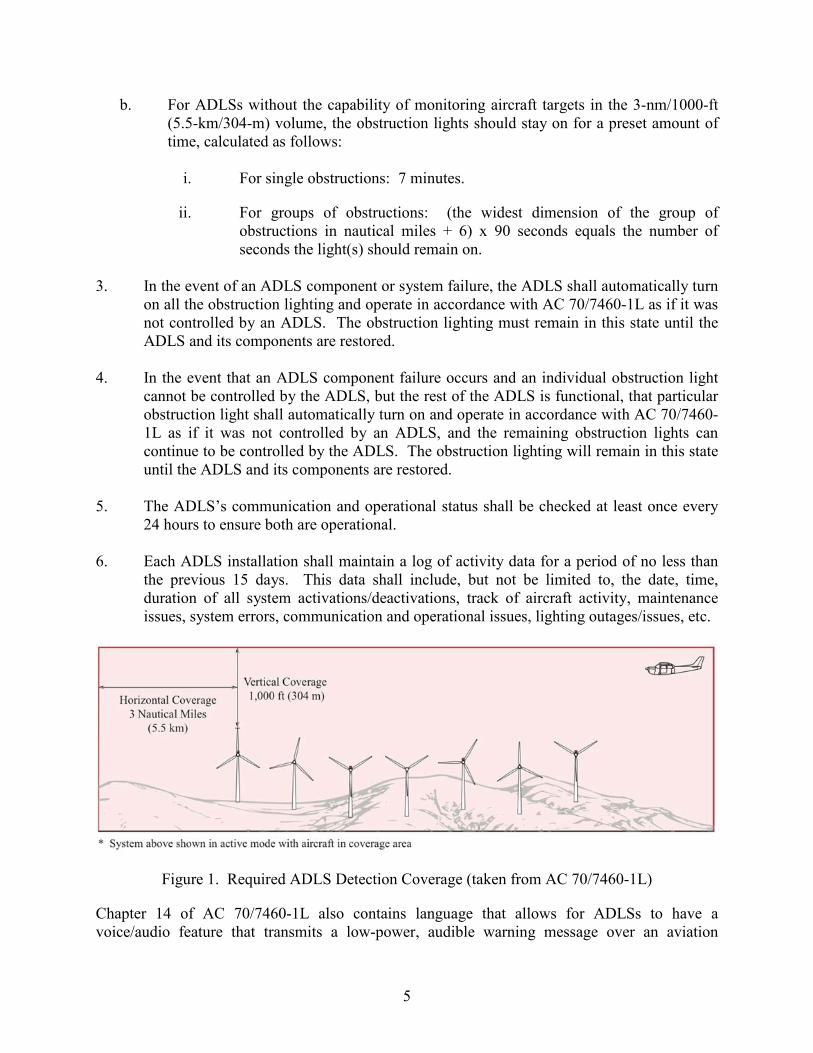
b. For ADLSs without the capability of monitoring aircraft targets in the 3-nm/1000-ft (5.5-km/304-m) volume, the obstruction lights should stay on for a preset amount of time, calculated as follows:
i. For single obstructions: 7 minutes.
ii. For groups of obstructions: (the widest dimension of the group of obstructions in nautical miles + 6) x 90 seconds equals the number of seconds the light(s) should remain on.
3. In the event of an ADLS component or system failure, the ADLS shall automatically turn
on all the obstruction lighting and operate in accordance with AC 70/7460-1L as if it was not controlled by an ADLS. The obstruction lighting must remain in this state until the ADLS and its components are restored.
4. In the event that an ADLS component failure occurs and an individual obstruction light
cannot be controlled by the ADLS, but the rest of the ADLS is functional, that particular obstruction light shall automatically turn on and operate in accordance with AC 70/7460-1L as if it was not controlled by an ADLS, and the remaining obstruction lights can continue to be controlled by the ADLS. The obstruction lighting will remain in this state until the ADLS and its components are restored.
5. The ADLS’s communication and operational status shall be checked at least once every
24 hours to ensure both are operational. 6. Each ADLS installation shall maintain a log of activity data for a period of no less than
the previous 15 days. This data shall include, but not be limited to, the date, time, duration of all system activations/deactivations, track of aircraft activity, maintenance issues, system errors, communication and operational issues, lighting outages/issues, etc.
Figure 1. Required ADLS Detection Coverage (taken from AC 70/7460-1L)
Chapter 14 of AC 70/7460-1L also contains language that allows for ADLSs to have a voice/audio feature that transmits a low-power, audible warning message over an aviation

6
frequency licensed by the FCC in the MULTICOM/UNICOM frequency band to provide pilots additional information on the obstruction they are approaching. The Laufer Wind ADS does not offer this option, so these requirements do not apply to this assessment.
LAUFER WIND ADS CHARACTERISTICS AND SPECIFICATIONS
The Laufer Wind ADS is a radar-activated warning lighting system designed for wind turbine farms and other obstructions, and follows the general description provided in AC 70/7460-1L. When there are no aircraft in the vicinity of the wind turbine farm or obstruction, the warning lights are off. When aircraft are detected in the vicinity, the lights are activated (turned on). When all aircraft have safely left the vicinity, the lights are deactivated (turned off). The Laufer Wind ADS allows wind turbine farm warning lights to remain safely off at night when aircraft are not in the area. The Laufer Wind ADS is comprised of four major subsystems: (1) radar(s), (2) obstruction light controller unit(s) (OLCU), (3) central controller, and (4) communications network, as shown in figure 2.
Figure 2. The Major Subsystems in the Laufer Wind ADS
LAUFER WIND ADS OPERATIONAL DESCRIPTION.
The Laufer Wind ADS operates as follows: • Aircraft that enter the light activation perimeter (3-NM/1000-ft (5.5-km/304-m) volume)
are detected and tracked by the radar(s). Aircraft tracking information is sent over the communication network to the central controller’s computer processor.

7
• The central controller fuses the radar tracking data and determines when to turn the lights on, and then sends a Lights-On command over the communication network to all OLCUs.
• The OLCUs turn on the obstruction lights. • Radar(s) track the aircraft away from the wind turbine farm until it exits the light
activation perimeter (3-NM/1000-ft (5.5-km/304-m) volume). • The central controller determines when to turn the lights off by verifying that all aircraft
that entered the light activation perimeter have exited the perimeter. • The central controller sends a Lights-Off command over the communication network to
all OLCUs that turn off the obstruction lights. LAUFER WIND ADS RADAR DESCRIPTION.
Laufer Wind Group has developed a proprietary X-band pulsed Doppler radar specifically for the Laufer Wind ADS wind turbine farm application. The key features of the Laufer Wind ADS radar are as follows: • Advanced magnetron-based pulsed Doppler radar provides clutter suppression for
enhanced aircraft detection and tracking. • Radar detects and tracks small general aviation aircraft of a 1-square-meter radar cross
section to ranges greater than 12 km (7.456 mi) in adverse weather. • Radar has FCC-approved wireless and Electrical Testing Laboratories (ETL) safety
certificates (http://www.intertek.com/marks/etl/). • Radar operating temperature range: -40°C (-40°F) to +55°C (131°F). • Radar operating wind speed: up to 55 m/sec (123 mph). • Environmental: Meets IP56 “Ingress Protection” rating, as defined in International
Standard EN 60529 (https://en.wikipedia.org/wiki/IP_Code). • Radar and radome/antenna size and weight are approximately 0.30 (11.81 in.) by 0.38
(14.96 in.) by 0.38 m (14.96 in.) (radar housing), 1.27 (50 in.) by 0.48 (18.9 in.) by 0.28 m (11.02 in.) (antenna), and weighs ~46 kg (101.4 lb) (total), respectively.
• Radar draws less than 300W of alternating current line power. • Built-in system test capability that includes: • Prefailure notification.

8
• Out-of-tolerance critical voltages, currents, and electrical and mechanical operating temperatures trigger notification of required prefailure maintenance.
• Critical for fail-safe operation.
There are no intrinsic speed limits to the radar’s ability to detect and track targets. Upper and lower speed limits are definable in the software. Ground vehicles can travel at speeds that may overlap with aircraft speeds, including gliding ultra-lights. Laufer Wind has developed a variety of techniques to deal with the ground traffic, which involves tuning for a particular radar scene, taking roads into account, etc. The Laufer Wind ADS radar also successfully tracks helicopters. The rotating blades of helicopters produce high-amplitude Doppler frequency signals that are easily detected by the radar. The Laufer Wind ADS radar can identify and track helicopters while they are moving and continue to track them while hovering in a stationary location. OBSTRUCTION LIGHT CONTROLLER UNIT DESCRIPTION.
The OLCU is a Laufer Wind Group electronics module that interfaces with and controls third-party, FAA-approved obstruction lights. The key features of the OLCU are as follows: • Turns obstruction lights on and off, including Global Positioning System (GPS)-
synchronized lights. One OLCU module is required for each wind turbine. • Maintains a fail-safe countdown timer, which turns on the obstruction warning light if
communication is lost with the communication network or central controller. • Can control high-intensity white flashing, medium-intensity red flashing, or low-intensity
lights. • Can control meteorological (met) tower lighting. • Has ETL-approved safety and emissions certificates. • Has an operating temperature range of -40°C (-40°F) to +55°C (131°F). • Has an IP66 “Ingress Protection” rating, as defined in International Standard EN 60529
(environmental rating). • Size and weight are approximately 0.3 (11.81 in.) by 0.25 (9.843 in.) by 0.15 m
(5.906 in.) and weighs ~7.5 kg (16.53 lb), respectively, and draws less than 200W of alternating current line power.

9
CENTRAL CONTROLLER DESCRIPTION.
The central controller computer processes data from all of the Laufer Wind ADS radars and lights, determines if aircraft are within warning distance of the wind turbine farm or other obstruction, and commands the obstruction lights to turn on or off accordingly. The central controller also interfaces with and provides Laufer Wind ADS status to wind turbine farm operators, providing a real-time radar tracking map that shows where low-flying aircraft are located within the vicinity of the wind turbine farm. The key features of the central controller are as follows: • Provides total control of the Laufer Wind ADS. • Fuses aircraft track data from all radars to create a comprehensive picture of the wind
turbine farm’s airspace. • Determines when the lights are activated and deactivated by generating on/off light
control signals. • Monitors the operational health status of radars, obstruction light controllers, and
communication network. • Provides a complete logging function. It logs all target tracks as well as light on and off
events. COUNTING AIRCRAFT INGRESS AND EGRESS.
The central controller uses Laufer Wind ADS’s aircraft counting method, which effectively deals with the case where one or more aircraft fly over the wind turbine farm and radars cannot reliably detect the aircraft. • As aircraft enter the protected area around a wind turbine farm, the central controller
counts the number of aircraft targets. • When this count is positive, the lights are turned on. • If the aircraft are not in the radars’ field of view because they have flown over the wind
turbine farm, the lights are kept on by the positive aircraft count. • The radars track all aircraft away from the wind turbine farm, decrementing the count as
each aircraft leaves the protected area. • When the count is zero, indicating there are no aircraft in the area, the lights are turned
off.
10
• This method assures that the lights are kept on for slow moving or loitering aircraft and hovering helicopters. It also allows for the lights to be turned off immediately upon aircraft leaving the protected area around the wind turbine farm.
The Laufer Wind ADS’s counting aircraft method provides the continuous monitoring necessary to meet the requirements of paragraph 14.2.2.1 of AC 70/7460-1L. LAUFER WIND ADS PERIMETERS.
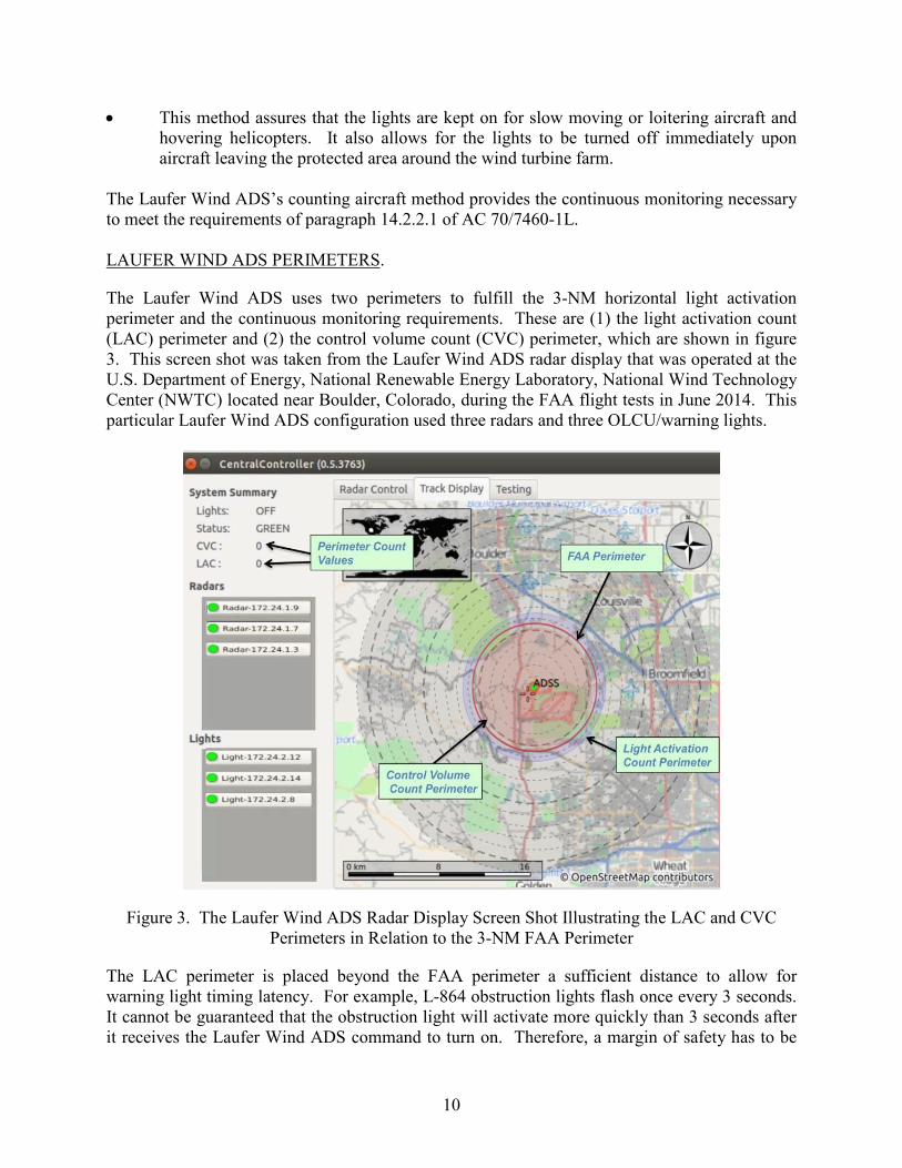
The Laufer Wind ADS uses two perimeters to fulfill the 3-NM horizontal light activation perimeter and the continuous monitoring requirements. These are (1) the light activation count (LAC) perimeter and (2) the control volume count (CVC) perimeter, which are shown in figure 3. This screen shot was taken from the Laufer Wind ADS radar display that was operated at the U.S. Department of Energy, National Renewable Energy Laboratory, National Wind Technology Center (NWTC) located near Boulder, Colorado, during the FAA flight tests in June 2014. This particular Laufer Wind ADS configuration used three radars and three OLCU/warning lights.
Figure 3. The Laufer Wind ADS Radar Display Screen Shot Illustrating the LAC and CVC Perimeters in Relation to the 3-NM FAA Perimeter
The LAC perimeter is placed beyond the FAA perimeter a sufficient distance to allow for warning light timing latency. For example, L-864 obstruction lights flash once every 3 seconds. It cannot be guaranteed that the obstruction light will activate more quickly than 3 seconds after it receives the Laufer Wind ADS command to turn on. Therefore, a margin of safety has to be

11
added beyond the FAA perimeter such that the Lights-On command is received with sufficient time allowance for the lights to reach full intensity before the aircraft penetrates the FAA 3-NM perimeter. Tracks crossing into the LAC perimeter cause the Laufer Wind ADS to initiate turning the lights on. The central controller keeps an active count of the number of active aircraft tracks within the LAC perimeter. The smaller CVC perimeter is used to continuously monitor and account for the presence of aircraft within the FAA 3-NM perimeter, even if aircraft over the wind turbine farm are not being directly tracked by the Laufer Wind ADS. CVC perimeter inbound aircraft boundary crossings cause the CVC to increment, while CVC perimeter egress boundary crossings cause the CVC to decrement. If an aircraft overflies the radars and the track is lost, the positive CVC count is used to keep the lights on. The radars will re-acquire the aircraft track before it leaves the CVC perimeter and decrement the CVC count only at the perimeter crossing. If the LAC or the CVC are greater than zero, the lights are kept on. If both the LAC and CVC are equal to zero, and the system health status is GREEN (indicating healthy), then the lights are turned off. LAUFER WIND ADS FAIL-SAFE DESIGN.
The Laufer Wind ADS provides multiple layers of fail-safe protection. When any failure occurs, the obstruction lights are turned on until the Laufer Wind ADS and its components are restored. • Protection From Radar Failure: The central controller continuously monitors the health
status of the radar units and will actively turn on all of the obstruction lights if the radar failures are detected.
• Protection From Network and Central Controller Failure: Each OLCU maintains an
internal countdown timer that will turn on its associated obstruction light if a system healthy message is not received through the network from the central controller.
• Protection From OLCU Failure: The OLCU becomes passive (lightning protection
maintained) upon failure, defaulting to turning on the associated obstruction light.
LAUFER WIND ADS INSTALLATION DESCRIPTION AT THE NWTC
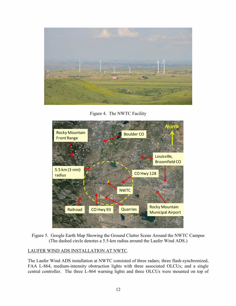
Laufer Wind installed its ADS at the NWTC on a small wind turbine farm containing a mix of turbines manufactured by different vendors, arranged on top of a small, mesa-like hill in a random layout, as shown in figure 4. NWTC presents a complicated scene for radar technologies because it includes the nearby Rocky Mountain front range hills to the west, surrounding cities such as Boulder and Louisville to the north and east, the busy Rocky Mountain Metropolitan Airport (KBJC) to the southeast, railroads and quarries and industrial installations to the south and west, busy nearby highways that pass north-south and east-west, and large wind turbine structures and towers on the NWTC campus. Figure 5 shows a map of NWTC and its surroundings that include various ground clutter callouts. The Laufer Wind ADS scans low along the horizon (the radar beam elevation is ~11 degrees above the horizon) to optimize detection of low-flying aircraft approaching the wind turbine farm.
12
Figure 4. The NWTC Facility
Figure 5. Google Earth Map Showing the Ground Clutter Scene Around the NWTC Campus (The dashed circle denotes a 5.5-km radius around the Laufer Wind ADS.)
LAUFER WIND ADS INSTALLATION AT NWTC.
The Laufer Wind ADS installation at NWTC consisted of three radars; three flash-synchronized, FAA L-864, medium-intensity obstruction lights with three associated OLCUs; and a single central controller. The three L-864 warning lights and three OLCUs were mounted on top of
Boulder CO
Rocky MountainMunicipal Airport
Rocky MountainFront Range
NWTC
CO Hwy 93
CO Hwy 128
Railroad Quarries
5.5 km (3 nmi) radius
Louisville,Broomfield CO
North
13
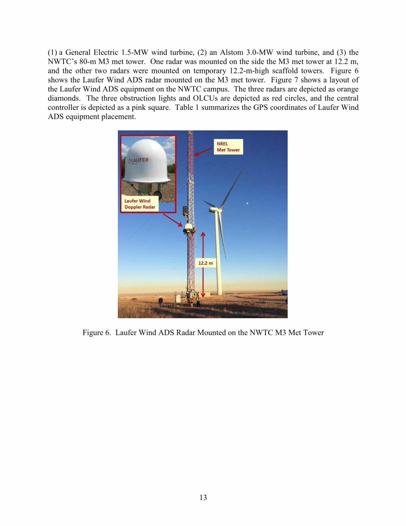
(1) a General Electric 1.5-MW wind turbine, (2) an Alstom 3.0-MW wind turbine, and (3) the NWTC’s 80-m M3 met tower. One radar was mounted on the side the M3 met tower at 12.2 m, and the other two radars were mounted on temporary 12.2-m-high scaffold towers. Figure 6 shows the Laufer Wind ADS radar mounted on the M3 met tower. Figure 7 shows a layout of the Laufer Wind ADS equipment on the NWTC campus. The three radars are depicted as orange diamonds. The three obstruction lights and OLCUs are depicted as red circles, and the central controller is depicted as a pink square. Table 1 summarizes the GPS coordinates of Laufer Wind ADS equipment placement.
Figure 6. Laufer Wind ADS Radar Mounted on the NWTC M3 Met Tower

14
Figure 7. Google Earth Map Showing the Laufer Wind ADS Equipment Layout on the NWTC Campus
Table 1. The GPS Coordinates of Laufer Wind ADS Equipment Placement at NWTC
Component Latitude Longitude GE 1.5-MW wind turbine OLCU 39° 54.768'N 105° 13.176'W Alstom 3.0-MW wind turbine OLCU 39° 54.617'N 105° 13.261'W M3 met tower OLCU, central controller 39° 54.616'N 105° 13.376'W Radar 1 (scaffold tower) 39° 54.735'N 105° 13.181'W Radar 2 (scaffold tower) 39° 54.351'N 105° 13.488'W Radar 3 (M3 met tower) 39° 54.616'N 105° 13.376'W
LAUFER WIND ADS RADAR COVERAGE AT NWTC.
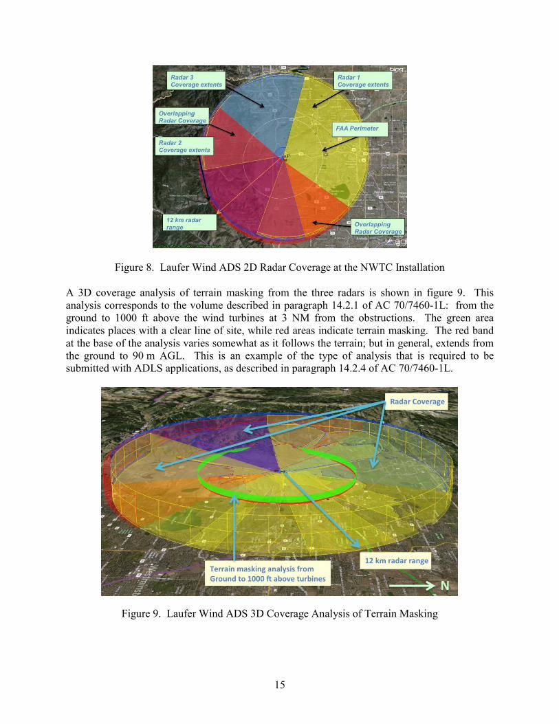
A plan view of the two-dimensional (2D) radar coverage generated by the three Laufer Wind ADS radars installed at NWTC is presented in figure 8. The radar coverage is shown out to a range of 12 km and includes the FAA 3-NM (~5.5-km) perimeter for reference. Radar 1 coverage is depicted in yellow and is directed toward the east, Radar 2 coverage is shown in red and is directed from northwest to the southeast, and Radar 3 coverage is shown in blue and is directed primarily to the west. Regions of overlapping radar coverage are also called out in figure 8. Radar placement was designed to avoid any single-radar shadowing effects from the large nearby wind turbines and provided unobstructed radar coverage in all directions.
North
15
Figure 8. Laufer Wind ADS 2D Radar Coverage at the NWTC Installation A 3D coverage analysis of terrain masking from the three radars is shown in figure 9. This analysis corresponds to the volume described in paragraph 14.2.1 of AC 70/7460-1L: from the ground to 1000 ft above the wind turbines at 3 NM from the obstructions. The green area indicates places with a clear line of site, while red areas indicate terrain masking. The red band at the base of the analysis varies somewhat as it follows the terrain; but in general, extends from the ground to 90 m AGL. This is an example of the type of analysis that is required to be submitted with ADLS applications, as described in paragraph 14.2.4 of AC 70/7460-1L.
Figure 9. Laufer Wind ADS 3D Coverage Analysis of Terrain Masking

16
THE FAA TESTS OF THE LAUFER WIND ADS AT THE NWTC
THE FAA FLIGHT EVALUATION.
To properly assess the performance of the Laufer Wind ADS, ATR personnel developed a series of flight patterns to evaluate the system’s response to aircraft operating around the wind turbine farm at various altitudes, flight paths, speed, etc. Six specific flight patterns were flown multiple times, each designed to test a specific parameter of the Laufer Wind ADS to determine if the system meets the requirements in AC 70/7460-1L. The six flight patterns are described below. 1. The aircraft flew directly to and over the wind turbine farm at 750 ft AGL, three times at
various headings. 2. The aircraft flew adjacent to the wind turbine farm at 750 ft AGL, two times at various
headings. 3. The aircraft flew over the wind turbine farm at 1000 ft AGL, two times at various
headings. 4. The aircraft flew to and over the wind turbine farm at an altitude less than 1000 ft AGL,
completing several tight circles immediately over the wind turbine farm, and then exiting the wind turbine farm at a different heading from the entry heading. This was completed two times at various headings.
5. The aircraft flew to and over the wind turbine farm at least 1500 ft AGL and then steeply
descended into the wind turbine farm. This was completed two times at various headings.
6. The aircraft flew directly to the wind turbine farm at 500 to 700 ft AGL from a location
where terrain or other structures masked the aircraft from being initially detected by the Laufer Wind ADS. The intent of this pattern was to identify how quickly the Laufer Wind ADS can detect the aircraft without the benefit of early detection.
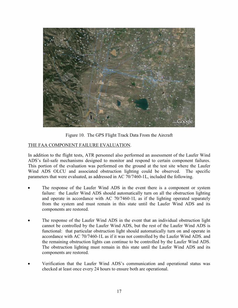
ATR personnel used a rental Cessna 172, which was flown by a pilot with a commercial pilot certificate and approximately 600 hours of flight time, to conduct the flight patterns. All flights were operated out of the Rocky Mountain Metropolitan Airport (KBJC), which was located just a few miles to the east of the Laufer Wind ADS installation. Figure 10 shows the flight tracks (shown in blue) recorded by a GPS unit on board the aircraft overlaid on a Google Earth map image.
17
Figure 10. The GPS Flight Track Data From the Aircraft
THE FAA COMPONENT FAILURE EVALUATION.
In addition to the flight tests, ATR personnel also performed an assessment of the Laufer Wind ADS’s fail-safe mechanisms designed to monitor and respond to certain component failures. This portion of the evaluation was performed on the ground at the test site where the Laufer Wind ADS OLCU and associated obstruction lighting could be observed. The specific parameters that were evaluated, as addressed in AC 70/7460-1L, included the following. • The response of the Laufer Wind ADS in the event there is a component or system
failure: the Laufer Wind ADS should automatically turn on all the obstruction lighting and operate in accordance with AC 70/7460-1L as if the lighting operated separately from the system and must remain in this state until the Laufer Wind ADS and its components are restored.
• The response of the Laufer Wind ADS in the event that an individual obstruction light
cannot be controlled by the Laufer Wind ADS, but the rest of the Laufer Wind ADS is functional: that particular obstruction light should automatically turn on and operate in accordance with AC 70/7460-1L as if it was not controlled by the Laufer Wind ADS. and the remaining obstruction lights can continue to be controlled by the Laufer Wind ADS. The obstruction lighting must remain in this state until the Laufer Wind ADS and its components are restored.
• Verification that the Laufer Wind ADS’s communication and operational status was
checked at least once every 24 hours to ensure both are operational.

18
• Verifification that the Laufer Wind ADS was able to detect an aircraft with a cross-sectional area of 1 square meter or more within the detection area.
• Verification that the Laufer Wind ADS maintains a log of activity data for a period of no
less than the previous 15 days. This data shall include, but not be limited to, the date, time, duration of all system activations/deactivations, track of aircraft activity, maintenance issues, system errors, communication and operational issues, lighting outages/issues, etc.
• Verification that the Laufer Wind ADS components do not use the devices identified in
47 CFR Part 15, “Radio Frequency Devices” [4]. • If equipped with a voice/audio option, verify that the Laufer Wind ADS operated within
the performance specifications for the voice/audio option provided in Chapter 14 of AC 70/7460-1L (See appendix A).
RESULTS
The performance assessment of the Laufer Wind ADS was based on the specifications and criteria provided in AC 70/7460-1L. AC 70/7460-1L lists specifications for basic functions, detection performance, and system output. The following sections document the performance of the Laufer Wind ADS along with the data collected during the performance assessment and discuss how it relates to the AC 70/7460-1L performance specifications. BASIC FUNCTION EVALUATION.
Prior to the flight evaluation, the Laufer Wind ADS was turned on and calibrated, and ATR personnel verified that the system was up and running. ATR personnel also verified that, without any aircraft present in the area, the system continuously scanned the area and kept the obstruction lighting off. Before beginning the scheduled flight patterns, ATR personnel confirmed that the system was standing by and was not tracking any other aircraft in the area. With the system ready and the obstruction lighting off, ATR personnel proceeded to evaluate the Laufer Wind ADS’s detection performance. During the test flights, the Laufer Wind ADS recorded radar tracks for all airborne targets operating within the vicinity of the system while the performance assessment was being conducted. Figure 11 shows a screenshot of the Laufer Wind ADS radar display showing a record of the entire FAA flight pattern. The solid lines represent the real-time output of the tracks produced by the Laufer Wind ADS radars, and the dotted lines represent the tracks recorded by the GPS on board the aircraft. It is clearly observable that radar tracks from the Laufer Wind ADS and the GPS closely coincide with each other. The different colored radar tracks indicate when the aircraft was flying through the coverage of different radars. The Laufer Wind ADS radars continuously tracked the aircraft at a range greater than 7.5 mi (12 km) to the north, east, and south. The aircraft tracking range to the west was limited to just under 5.6 mi (9 km) because of terrain obscuration from the mountains. The 5.6-mi (9-km) tracking range

19
still provided ample space for the Laufer Wind ADS to detect and activate the obstruction lights when the aircraft crossed into the 3-NM (5.5-km) FAA boundary requirement.
Figure 11. Laufer Wind ADS Radar Display Showing Cumulative Radar Tracks (solid lines) Overlaid on the Aircraft’s GPS Track (dotted lines)
DETECTION PERFORMANCE EVALUATION.
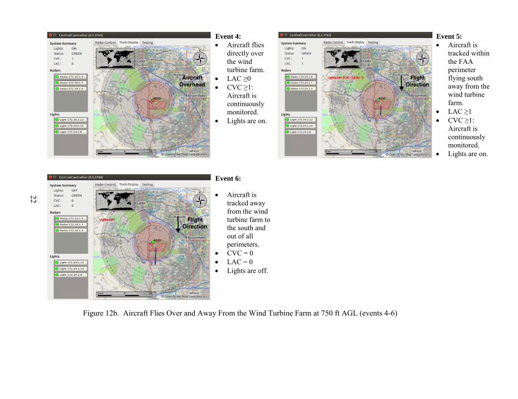
To demonstrate that the Laufer Wind ADS was able to meet the detection performance requirements for an ADLS, ATR personnel conducted a series of flight maneuvers designed to test the system’s detection capabilities. Descriptions of the maneuver and the results of the Laufer Wind ADS’s detection capability are as follows: • Aircraft Flies Directly to, Over, and Away From the Wind Turbine Farm at 750 ft AGL
The Laufer Wind ADS was able to detect the aircraft well outside the 3-NM (5.5-km) perimeter and activated the obstruction lights when the aircraft was 3.2 NM away, flying toward the wind turbine farm from the east. Figure 12a shows events 1-3 for this flight pattern, as detected by the Laufer Wind ADS. After the aircraft flew over the wind turbine farm, the Laufer Wind ADS turned off the obstruction lights when the aircraft was approximately 3.6 NM away from the wind turbine farm heading south. Figure 12b shows events 4-6 for this flight pattern, as detected by the Laufer Wind ADS.
• Aircraft Flies Adjacent to the Wind Turbine Farm at 750/1000 ft AGL
The Laufer Wind ADS was able to detect the aircraft well outside the 3-NM (5.5-km) perimeter and activated the obstruction lights when the aircraft turned inbound toward the

20
wind turbine farm 3.2 NM away. After the aircraft flew by the wind turbine farm, the Laufer Wind ADS turned off the obstruction lights when the aircraft was approximately 3.7 NM away heading north. Figure 13 shows events 7-10 for this flight pattern, as detected by the Laufer Wind ADS.
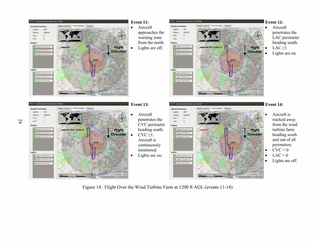
• Aircraft Flies Over the Wind Turbine Farm at 1200 ft AGL
The Laufer Wind ADS was able to detect the aircraft well outside the 3-NM (5.5-km) perimeter, demonstrated that it could detect the aircraft within the 1000-ft area above the height of the tallest obstruction (200-ft wind turbine), and activated the obstruction lights when the aircraft flew toward the wind turbine farm. After the aircraft flew over the wind turbine farm, the Laufer Wind ADS turned off the obstruction lights when the aircraft was approximately 3.8 NM away from the wind turbine farm to the south. Figure 14 shows events 11-14 for this flight pattern, as detected by the Laufer Wind ADS.
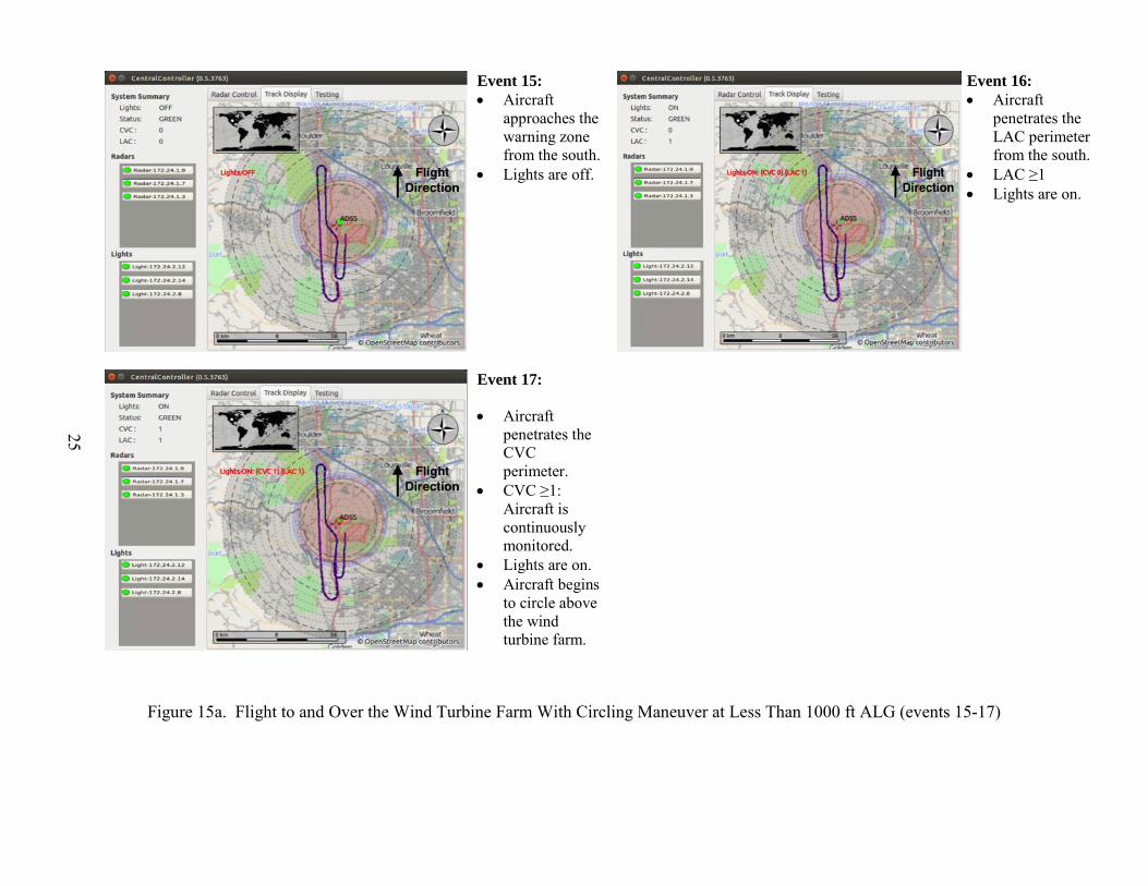
• Flight to and Over the Wind Turbine Farm With Circling Maneuvers at Less Than 1000 ft AGL
The Laufer Wind ADS was able to detect the aircraft well outside the 3-NM (5.5-km) perimeter and demonstrated that it could detect the aircraft within the 1000-ft area above the wind turbine farm; the Laufer Wind ADS was able to turn on the obstruction lights, and keep track of the aircraft even though the aircraft was conducting a series of steep circling maneuvers immediately over the wind turbine farm. After the aircraft completed the circling maneuvers and exited the area at a random heading, the Laufer Wind ADS recognized it as the same aircraft that had entered the perimeter and turned off the obstruction lights as required. Figures 15a and 15b show events 15-20 for this flight pattern, as detected by the Laufer Wind ADS.
• Flight Descending Into Wind Turbine Farm From 1500 ft AGL
The Laufer Wind ADS was able to detect the aircraft well outside the 3-NM (5.5-km) perimeter, demonstrated that it could detect the aircraft when it was descending into the wind turbine farm, and turned on the obstruction lights. After the aircraft completed the descent and exited the area at a random heading, the Laufer Wind ADS turned off the obstruction lights as required. Figure 16 shows events 21-23 for this flight pattern, as detected by the Laufer Wind ADS.
• Flight to the Wind Turbine Farm With the Aircraft Initially Hidden Behind a Mountain
The Laufer Wind ADS was able to detect the aircraft as soon as it appeared from behind a mountain west of the wind turbine farm. As soon as the Laufer Wind ADS detected the aircraft (still outside the 3-NM (5.5-km) perimeter), the system continued to monitor the aircraft’s track and activated the obstruction lights when the aircraft entered the 3-NM (5.5-km) perimeter. After the aircraft flew over the wind turbine farm and exited the area, the Laufer Wind ADS turned off the obstruction lights as required. Figure 17 shows events 24-26 for this flight pattern, as detected by the Laufer Wind ADS.

21
Event 1: • Aircraft
approaches the warning zone from the east.
• Lights are off.
Event 2: • Aircraft
penetrates the LAC perimeter.
• LAC ≥1 • Lights are on.
Event 3:
• Aircraft penetrates the CVC perimeter.
• CVC ≥1: Aircraft is continuously monitored.
• Lights are on.
Figure 12a. Aircraft Flies Directly to and Over the Wind Turbine Farm at 750 ft AGL (events 1-3)
22
Event 4: • Aircraft flies
directly over the wind turbine farm.
• LAC ≥0 • CVC ≥1:
Aircraft is continuously monitored.
• Lights are on.
Event 5: • Aircraft is
tracked within the FAA perimeter flying south away from the wind turbine farm.
• LAC ≥1 • CVC ≥1:
Aircraft is continuously monitored.
• Lights are on.
Event 6:
• Aircraft is tracked away from the wind turbine farm to the south and out of all perimeters.
• CVC = 0 • LAC = 0 • Lights are off.
Figure 12b. Aircraft Flies Over and Away From the Wind Turbine Farm at 750 ft AGL (events 4-6)

23
Event 7: • Aircraft
approaches the warning zone from the south.
• Lights are off.
Event 8: • Aircraft
penetrates the LAC perimeter from the south.
• LAC ≥1 • Lights are on.
Event 9:
• Aircraft penetrates the CVC perimeter.
• CVC ≥1: Aircraft is continuously monitored.
• Lights are on.
Event 10:
• Aircraft is tracked away from the wind turbine farm to the north and out of all perimeters.
• CVC = 0 • LAC = 0 • Lights are off.
Figure 13. Flight Adjacent to Wind Turbine Farm Within 3 NM 750/1000 ft AGL (events 7-10)
24
Event 11: • Aircraft
approaches the warning zone from the north.
• Lights are off.
Event 12: • Aircraft
penetrates the LAC perimeter heading south.
• LAC ≥1 • Lights are on.
Event 13:
• Aircraft penetrates the CVC perimeter heading south.
• CVC ≥1: Aircraft is continuously monitored.
• Lights are on.
Event 14:
• Aircraft is tracked away from the wind turbine farm heading south and out of all perimeters.
• CVC = 0 • LAC = 0 • Lights are off.
Figure 14. Flight Over the Wind Turbine Farm at 1200 ft AGL (events 11-14)
25
Event 15: • Aircraft
approaches the warning zone from the south.
• Lights are off.
Event 16: • Aircraft
penetrates the LAC perimeter from the south.
• LAC ≥1 • Lights are on.
Event 17:
• Aircraft penetrates the CVC perimeter.
• CVC ≥1: Aircraft is continuously monitored.
• Lights are on. • Aircraft begins
to circle above the wind turbine farm.
Figure 15a. Flight to and Over the Wind Turbine Farm With Circling Maneuver at Less Than 1000 ft ALG (events 15-17)

26
Event 18: • Aircraft flies
directly over the wind turbine farm and circles.
• LAC = 0 • CVC = 1:
Aircraft is continuously monitored.
• Lights are on.
Event 19: • Aircraft is
tracked within the FAA perimeter flying north away from the wind turbine farm.
• LAC ≥1 • CVC = 1:
Aircraft is continuously monitored.
• Lights are on.
Event 20:
• Aircraft is tracked away from the wind turbine farm and out of all perimeters to the north.
• CVC = 0 • LAC = 0 • Lights are off.
Figure 15b. Continuation of Circling Flight Over the Wind Turbine Farm at Less Than 1000 ft AGL, Then Exit to the North (events 18-20)

27
Event 21: • Aircraft turns
to the south and approaches the warning zone at 1500 ft AGL.
• Lights are off.
Event 22: • Aircraft
penetrates the LAC perimeter in a steep descent toward the wind turbine farm.
• LAC ≥1 • Lights are on.
Event 23:
• Aircraft is tracked within the FAA perimeter.
• LAC ≥1 • CVC ≥1:
Aircraft is continuously monitored.
• Lights are on.
Figure 16. Flight Descending Into Wind Turbine Farm From 1500 ft AGL (events 21-23)

28
Event 24: • Aircraft
approaches the warning zone from the west—suddenly appearing from behind the mountain.
• Lights are off.
Event 25: • Aircraft
penetrates the LAC perimeter heading east.
• LAC ≥1 • Lights are on.
Event 26:
• Aircraft is tracked within the FAA perimeter flying over wind turbine farm.
• LAC ≥1 • CVC ≥1:
Aircraft is continuously monitored.
• Lights are on.
Figure 17. Flight to the Wind Turbine Farm With Aircraft Initially Hidden Behind a Mountain (events 24-26)

29
COMPONENT FAILURE EVALUATION.
To demonstrate that the Laufer Wind ADS was able to meet the component failure requirements for an ADLS, ATR personnel conducted a series of activities designed to test the system’s component failure responses. Descriptions of the activities and the results of the Laufer Wind ADS’s failure response are as follows: • Individual Component Failure
ATR personnel confirmed that when an individual component of the Laufer Wind ADS was disconnected from the system or disabled, the Laufer Wind ADS automatically turned on all the obstruction lights as if the lights operated separately from the system. The obstruction lighting remained in this state until the Laufer Wind ADS component was plugged back in. Once the system recognized that the component was operating correctly, the lights were turned off, and the system went into standby mode.
• Obstruction Light Control
ATR personnel confirmed that when communication between the Laufer Wind ADS and an obstruction light was lost, the obstruction light remained on, while the rest of the obstruction lights remained under the control of the Laufer Wind ADS. The Laufer Wind ADS used a constant communication link between the OLCU and the obstruction light that instructs the lights to stay off until commanded otherwise. As a result, when the obstruction light loses communication, it defaults to an on condition. Once the obstruction light regained communication, the system turned the light off and the system went into standby mode.
• Communication and Status Monitoring
ATR personnel verified that the Laufer Wind ADS’ communication and operational status were being checked at least once every 24 hours to ensure both are operational. In fact, the Laufer Wind ADS exceeded this requirement by performing constant communication and status monitoring, which could give the operator a near instantaneous status of the system.
• Target Size
ATR personnel confirmed that the Laufer Wind ADS could detect an object with a cross-sectional area of 1 square meter or more within the detection area. This was accomplished by flying an aircraft straight toward the Laufer Wind ADS radar unit, which resulted in the system being able to detect the very narrow profile of the aircraft. In addition, the Laufer engineers demonstrated the system’s ability to detect birds that were flying near the NWTC facility. Airborne birds have a much smaller cross-sectional area, thus indicating that the Laufer Wind ADS exceeded this requirement.

30
• Activity Log
ATR personnel verified that that the Laufer Wind ADS maintained a log of data activity for a period of no less than the previous 15 days. This data included the date, time, duration of all system activations/deactivations, tracking aircraft activity, maintenance issues, system errors, communication and operational issues, and lighting outages/issues. The Laufer engineers indicated that the data could be stored for an indefinite amount of time, depending on the user’s requirement.
• The FCC Part 15 Compliance
Based on the documentation provided to the ATR personnel by the Laufer engineers, it was verified that the Laufer Wind ADS components do not use FCC Part 15 devices.
• Audio/Voice Option
The Laufer Wind ADS does not currently offer a voice/audio option, therefore it was not evaluated.
LAUFER WIND ADS OPERATIONAL EXPERIENCE.
Laufer Wind has operated various ADS radars and OLCUs continuously for more than a year leading up to the FAA flight tests at NWTC in June 2014. The Laufer Wind ADS was extensively tested against small general aviation aircraft. Table 2 shows the test locations, the number of flight tests, and the number of flight test hours logged with the Laufer Wind ADS. These flight tests have further verified the performance, accuracy, and reliability of the Laufer Wind ADS in tracking small, low-flying aircraft in clear weather, heavy rain, and heavy snow storms.
Table 2. The Laufer Wind ADS Flight Test Summary Through June 2014
Location Flight Tests Flight Test Hours Bedford, New Hampshire 19 39 Deerfield, New Hampshire 5 12 NWTC, Louisville, Colorado 23 57 Total 47 108
It is interesting to note that during the period of time the Laufer Wind ADS installation was operated at the NWTC in Boulder, Colorado, the system was successful in keeping the obstruction lights off from sundown to sunrise approximately 94% of the time. This indicates that the Laufer Wind ADSs can have a significant, positive impact on light pollution and exposure to migratory bird populations by activating obstruction lights only when aircraft are in the vicinity of the obstructions.
31/32
CONCLUSIONS
The Federal Aviation Administration (FAA) Airport Technology Research and Development Branch evaluated the Laufer Wind Aircraft Detection System (ADS) at the U.S. Department of Energy National Renewal Energy Laboratory near Boulder, Colorado. A performance assessment, consisting of demonstrations, flight tests, and analysis of data were performed in June 2014 and concluded in November 2014. In this performance assessment, a series of flight patterns were flown against the system to demonstrate that it could meet the FAA’s performance requirements for aircraft detection lighting systems. The Laufer Wind ADS performed according to the manufacturer’s specifications and met the performance requirements identified in FAA Advisory Circular (AC) 70/7460-1L, “Obstruction Marking and Lighting.” In addition, the data collected during this performance assessment confirmed that the performance requirements provided in AC 70/7460-1L for ADLSs remain valid and provide for a technology that offers a satisfactory level of safety for the flying public, while at the same time, reduces the impact of obstruction lights on nearby communities and migratory bird populations.
REFERENCES
1. Gehring, Joelle, Ph.D., “Studies of Avian Collisions With Communication Towers: A Quantification of Fatalities at a Self-Supported Rescue 21 Tower and a Test of Different Tall Tower Lighting Systems, 2008 and 2009 Progress Report,” April 2010.
2. Caldwell, L. and Cuthbert, N.L., “Bird Mortality at Television Towers Near Cadillac,
Michigan,” The Jack-Pine Warbler, Vol. 41, No. 2, 1963, pp. 80-89. 3. Caldwell, L. and Wallace, G., “Collection of Migrating Birds at Michigan Television
Towers,” The Jack-Pine Warbler, Vol. 44, 1966, pp. 117-123. 4. U.S. Federal Register, Title 47 Code of Federal Regulations, Part 15, “Radio Frequency
Devices,” Government Printing Office, Washington, DC.
A-1
APPENDIX A—ADVISORY CIRCULAR 70/7460-1L, CHAPTER 14 AIRCRAFT DETECTION LIGHTING SYSTEMS
CHAPTER 14. AIRCRAFT DETECTION LIGHTING SYSTEMS
14.1 Purpose. Aircraft Detection Lighting Systems (ADLS) are sensor-based systems designed to detect aircraft as they approach an obstruction or group of obstructions; these systems automatically activate the appropriate obstruction lights until they are no longer needed by the aircraft. This technology reduces the impact of nighttime lighting on nearby communities and migratory birds and extends the life expectancy of obstruction lights. 14.2 General Standards. 14.2.1 The system should be designed with sufficient sensors to provide complete detection coverage for aircraft that enter a three-dimensional volume of airspace, or coverage area, around the obstruction(s) as follows: 1. Horizontal detection coverage shall provide for obstruction lighting to be activated and illuminated prior to aircraft penetrating the perimeter of the volume, which is a minimum of 3 NM (5.5 km) away from the obstruction or the perimeter of a group of obstructions. 2. Vertical detection coverage shall provide for obstruction lighting to be activated and illuminated prior to aircraft penetrating the volume, which extends from the ground up to 1,000 feet (304 m) above the highest part of the obstruction or group of obstructions, for all areas within the 3-NM (5.5-km) perimeter defined in subparagraph 14.2.1 1 above. 3. In some circumstances, it may not be possible to meet the volume area defined above because the terrain may mask the detection signal from acquiring an aircraft target within the 3-NM (5.5-km) perimeter. In these cases, the sponsor shall identify these areas in their application to the FAA for further evaluation. 4. In some situations, lighting not controlled by the ADLS may be required when the 3 NM (5.5-km) perimeter is not achievable to ensure pilots have sufficient warning before approaching the obstructions. 14.2.2 The ADLS should activate the obstruction lighting system in sufficient time to allow the lights to illuminate and synchronize to flash simultaneously prior to an aircraft penetrating the volume defined above. The lights shall remain on for a specific time period, as follows: 1. For ADLSs capable of continuously monitoring aircraft while they are within the 3 NM/1,000-foot (5.5-km/304-m) volume, the obstruction lights should stay on until the aircraft exits the volume. In the event detection of the aircraft is lost while being continuously monitored within the 3-NM/1,000-foot (5.5-km/304-m) volume, the ADLS should initiate a

A-2
30-minute timer and keep the obstruction lights on until the timer expires. This should provide the untracked aircraft sufficient time to exit the area and give the ADLS time to reset. 2. For ADLSs without the capability of monitoring aircraft targets in the 3 nm/1,000 foot (5.5-km/304-m) volume, the obstruction lights should stay on for a preset amount of time, calculated as follows: a. For single obstructions: 7 minutes. b. For groups of obstructions: (the widest dimension of the group of obstructions in nautical miles + 6) x 90 seconds equals the number of seconds the light(s) should remain on. 14.2.3 Acceptance of ADLS applications will be on a case-by-case basis and may be modified, adjusted, or denied based on proximity of the obstruction or group of obstructions to airports, low-altitude flight routes, military training areas, or other areas of frequent flight activity. It may be appropriate to keep certain obstructions closest to these known activity areas illuminated during the nighttime hours, while the remainder of the group’s obstruction lighting is controlled by the ADLS. 14.2.4 Project sponsors requesting ADLS use shall include in their application maps or diagrams indicating the location of the proposed sensors, the range of each sensor, and a visual indication showing how each sensor’s detection arc provides the full horizontal and vertical coverage, as required under paragraph 14.2.1. In the event that detection coverage is not 100% due to terrain masking, project sponsors should provide multiple maps or diagrams that indicate coverage at the affected altitudes. A sample diagram is shown in Figure A-27 in Appendix A. 14.2.5 Types of ADLS Component or System Failure Events. 1. In the event of an ADLS component or system failure, the ADLS shall automatically turn on all the obstruction lighting and operate in accordance with this AC as if it was not controlled by an ADLS. The obstruction lighting must remain in this state until the ADLS and its components are restored. 2. In the event that an ADLS component failure occurs and an individual obstruction light cannot be controlled by the ADLS, but the rest of the ADLS is functional, that particular obstruction light shall automatically turn on and operate in accordance with this AC as if it was not controlled by an ADLS, and the remaining obstruction lights can continue to be controlled by the ADLS. The obstruction lighting will remain in this state until the ADLS and its components are restored. 3. Complete light failure should be addressed in accordance with Chapter 2 paragraph 2.4. 14.2.6 The ADLS’s communication and operational status shall be checked at least once every 24 hours to ensure both are operational.

A-3/A-4
14.2.7 The ADLS shall be able to detect an aircraft with a cross-sectional area of 1 square meter or more within the volume, as required in subparagraphs 14.2.1 1 and 14.2.1 2. 14.2.8 Each ADLS installation shall maintain a log of activity data for a period of no less than the previous 15 days. This data shall include, but not be limited to, the date, time, duration of all system activations/deactivations, track of aircraft activity, maintenance issues, system errors, communication and operational issues, lighting outages/issues, etc. 14.2.9 Operational Frequencies. 1. FCC Part 15 devices cannot be used for this type of system. 2. Any frequency used for the operation of ADLS must be licensed through the FCC. 14.3 Voice/Audio Option. 14.3.1 ADLS may include an optional voice/audio feature that transmits a low-power, audible warning message over an aviation frequency licensed by the FCC in the MULTICOM/UNICOM frequency band to provide pilots additional information on the obstruction they are approaching. 14.3.2 The audible transmission should be in accordance with appropriate FAA and FCC regulations. Note: Using air traffic control frequencies in the 118-MHz to 137-MHz frequency band, which are not within the MULTICOM/UNICOM frequency band, are prohibited for this operation. 14.3.3 The audible message shall consist of three quick tones, followed by a verbal message that describes the type of obstruction the system is protecting. Appropriate terms to be used include tower(s), wind turbine(s), or power line(s). 14.3.4 The audible message should be repeated three times or until the system determines the aircraft is no longer within the audible warning area defined in the following paragraph. 14.3.5 The audible message should be considered as a secondary, final warning and should be activated when an aircraft is within 1/2 NM (926 m) horizontally and 500 feet (152 m) vertically of the obstruction. The use of, or variation to, the audible warning zone may occur, depending on site specific conditions or obstruction types.

B-1
APPENDIX B—LAUFER WIND AIRCRAFT DETECTION SYSTEM INFORMATION

B-2