technical & service manual - masterxoloda.rutechnical & service manual split-type, heat pump...
TRANSCRIPT
TECHNICAL & SERVICE MANUAL
SPLIT-TYPE, HEAT PUMP AIR CONDITIONERSSPLIT-TYPE, AIR CONDITIONERS
CONTENTS1. TECHNICAL CHANGES·································32. SAFETY PRECAUTION··································43. COMBINATION OF INDOOR AND OUTDOOR UNITS ···64. PART NAMES AND FUNCTIONS ··················75. SPECIFICATIONS···········································86. DATA ·····························································177. OUTLINES AND DIMENSIONS····················208. WIRING DIAGRAM·······································249. WIRING SPECIFICATIONS ··························30
10. REFRIGERANT SYSTEM DIAGRAM ··············3111. TROUBLESHOOTING···································3512. DISASSEMBLY PROCEDURE ·····················4913. PARTS LIST ··················································5314. OPTIONAL PARTS························Back Cover
Outdoor unit[model names]
PUH-P1VGAA
PUH-P1.6VGAA PU-P1.6VGAA
PUH-P1.6YGAA PU-P1.6YGAA
PUH-P2VGAA PU-P2VGAA
PUH-P2YGAA PU-P2YGAA
PUH-P2.5VGAA PU-P2.5VGAA
PUH-P2.5YGAA PU-P2.5YGAA
PUH-P3VGAA PU-P3VGAA
PUH-P3YGAA PU-P3YGAA
PUH-P4VGAA PU-P4VGAA
PUH-P4YGAA PU-P4YGAA
PUH-P5YGAA PU-P5YGAA
PUH-P6YGAA PU-P6YGAA
No.OC261REVISED EDITION-D
R407C
Model name indication
Revision:“13. PARTS LIST ” has been modified.
• Please void OC261 REVISED EDITION-C.
[Service Ref.]Service Ref. is on page 2.
OC261-D--1.qxp 05.2.18 11:07 AM Page 1
2
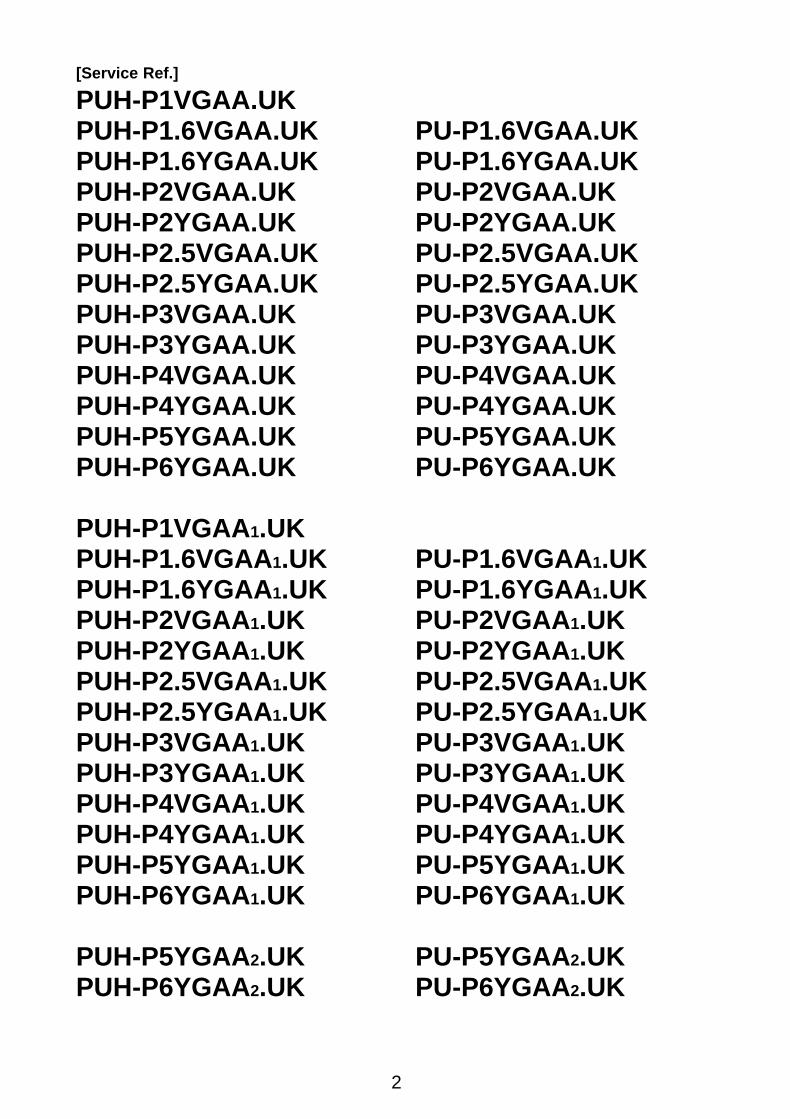
[Service Ref.]
PUH-P1VGAA.UKPUH-P1.6VGAA.UK PU-P1.6VGAA.UKPUH-P1.6YGAA.UK PU-P1.6YGAA.UKPUH-P2VGAA.UK PU-P2VGAA.UKPUH-P2YGAA.UK PU-P2YGAA.UKPUH-P2.5VGAA.UK PU-P2.5VGAA.UKPUH-P2.5YGAA.UK PU-P2.5YGAA.UKPUH-P3VGAA.UK PU-P3VGAA.UKPUH-P3YGAA.UK PU-P3YGAA.UKPUH-P4VGAA.UK PU-P4VGAA.UKPUH-P4YGAA.UK PU-P4YGAA.UKPUH-P5YGAA.UK PU-P5YGAA.UKPUH-P6YGAA.UK PU-P6YGAA.UK
PUH-P1VGAA1.UKPUH-P1.6VGAA1.UK PU-P1.6VGAA 1.UKPUH-P1.6YGAA1.UK PU-P1.6YGAA 1.UKPUH-P2VGAA1.UK PU-P2VGAA 1.UKPUH-P2YGAA1.UK PU-P2YGAA 1.UKPUH-P2.5VGAA1.UK PU-P2.5VGAA 1.UKPUH-P2.5YGAA1.UK PU-P2.5YGAA 1.UKPUH-P3VGAA1.UK PU-P3VGAA 1.UKPUH-P3YGAA1.UK PU-P3YGAA 1.UKPUH-P4VGAA1.UK PU-P4VGAA 1.UKPUH-P4YGAA1.UK PU-P4YGAA 1.UKPUH-P5YGAA1.UK PU-P5YGAA 1.UKPUH-P6YGAA1.UK PU-P6YGAA 1.UK
PUH-P5YGAA2.UK PU-P5YGAA 2.UKPUH-P6YGAA2.UK PU-P6YGAA 2.UK
OC261-D--1.qxp 05.2.18 11:07 AM Page 2
3
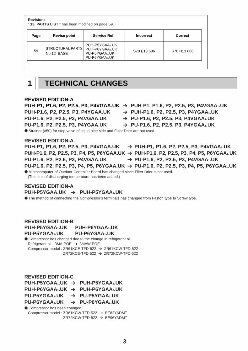
1 TECHNICAL CHANGES
REVISED EDITION-APUH-P1, P1.6, P2, P2.5, P3, P4VGAA.UK ➔ PUH-P1, P1.6, P2, P2.5, P3, P4VGAA 1.UKPUH-P1.6, P2, P2.5, P3, P4YGAA.UK ➔ PUH-P1.6, P2, P2.5, P3, P4YGAA 1.UKPU-P1.6, P2, P2.5, P3, P4VGAA.UK ➔ PU-P1.6, P2, P2.5, P3, P4VGAA 1.UKPU-P1.6, P2, P2.5, P3, P4YGAA.UK ➔ PU-P1.6, P2, P2.5, P3, P4YGAA 1.UK● Strainer (#50) for stop valve of liquid pipe side and Filter Drier are not used.
REVISED EDITION-APUH-P1, P1.6, P2, P2.5, P3, P4VGAA.UK ➔ PUH-P1, P1.6, P2, P2.5, P3, P4VGAA 1.UKPUH-P1.6, P2, P2.5, P3, P4, P5, P6YGAA.UK ➔ PUH-P1.6, P2, P2.5, P3, P4, P5, P6YGAA1.UKPU-P1.6, P2, P2.5, P3, P4VGAA.UK ➔ PU-P1.6, P2, P2.5, P3, P4VGAA 1.UKPU-P1.6, P2, P2.5, P3, P4, P5, P6YGAA.UK ➔ PU-P1.6, P2, P2.5, P3, P4, P5, P6YGAA 1.UK● Microcomputer of Outdoor Controller Board has changed since Filter Drier is not used.
(The limit of discharging temperature has been added.)
REVISED EDITION-APUH-P5YGAA.UK ➔ PUH-P5YGAA 1.UK● The method of connecting the Compressor’s terminals has changed from Faston type to Screw type.
REVISED EDITION-BPUH-P5YGAA 1.UK PUH-P6YGAA 1.UKPU-P5YGAA 1.UK PU-P6YGAA 1.UK● Compressor has changed due to the change in refrigerant oil.
Refrigerant oil : 3MA-POE ➔ 3MAW-POECompressor model : ZR61KCE-TFD-522 ➔ ZR61KCW-TFD-522
ZR72KCE-TFD-522 ➔ ZR72KCW-TFD-522
REVISED EDITION-CPUH-P5YGAA 1.UK ➔ PUH-P5YGAA 2.UKPUH-P6YGAA 1.UK ➔ PUH-P6YGAA 2.UKPU-P5YGAA 1.UK ➔ PU-P5YGAA 2.UKPU-P6YGAA 1.UK ➔ PU-P6YGAA 2.UK● Compressor has been changed.
Compressor model : ZR61KCW-TFD-522 ➔ BE82YADMTZR72KCW-TFD-522 ➔ BE96YADMT
Revision:“ 13. PARTS LIST ” has been modified on page 59.
Service Ref.Page IncorrectRevise point Correct
59STRUCTURAL PARTSNo.12 BASE
S70 H13 686S70 E13 686
PUH-P5YGAA2.UKPUH-P6YGAA2.UKPU-P5YGAA2.UKPU-P6YGAA2.UK
OC261-D--1.qxp 05.2.18 11:07 AM Page 3
4
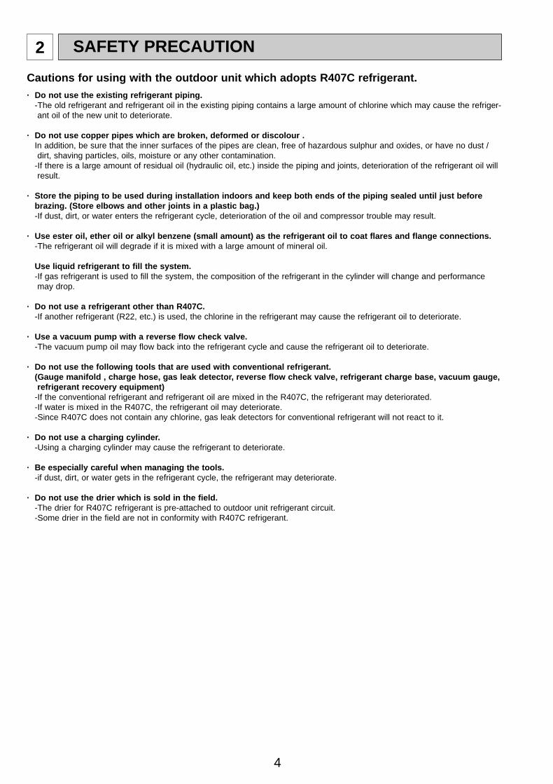
2 SAFETY PRECAUTION
Cautions for using with the outdoor unit which adopts R407C refrigerant.· Do not use the existing refrigerant piping.
-The old refrigerant and refrigerant oil in the existing piping contains a large amount of chlorine which may cause the refriger-ant oil of the new unit to deteriorate.
· Do not use copper pipes which are broken, deformed or discolour .In addition, be sure that the inner surfaces of the pipes are clean, free of hazardous sulphur and oxides, or have no dust /dirt, shaving particles, oils, moisture or any other contamination.
-If there is a large amount of residual oil (hydraulic oil, etc.) inside the piping and joints, deterioration of the refrigerant oil willresult.
· Store the piping to be used during installation indoors and keep both ends of the piping sealed until just beforebrazing. (Store elbows and other joints in a plastic bag.) -If dust, dirt, or water enters the refrigerant cycle, deterioration of the oil and compressor trouble may result.
· Use ester oil, ether oil or alkyl benzene (small amount) as the refrigerant oil to coat flares and flange connections.-The refrigerant oil will degrade if it is mixed with a large amount of mineral oil.
Use liquid refrigerant to fill the system.-If gas refrigerant is used to fill the system, the composition of the refrigerant in the cylinder will change and performancemay drop.
· Do not use a refrigerant other than R407C.-If another refrigerant (R22, etc.) is used, the chlorine in the refrigerant may cause the refrigerant oil to deteriorate.
· Use a vacuum pump with a reverse flow check valve.-The vacuum pump oil may flow back into the refrigerant cycle and cause the refrigerant oil to deteriorate.
· Do not use the following tools that are used with conventional refrigerant.(Gauge manifold , charge hose, gas leak detector, reverse flow check valve, refrigerant charge base, vacuum gauge,refrigerant recovery equipment)
-If the conventional refrigerant and refrigerant oil are mixed in the R407C, the refrigerant may deteriorated.-If water is mixed in the R407C, the refrigerant oil may deteriorate.-Since R407C does not contain any chlorine, gas leak detectors for conventional refrigerant will not react to it.
· Do not use a charging cylinder.-Using a charging cylinder may cause the refrigerant to deteriorate.
· Be especially careful when managing the tools.-if dust, dirt, or water gets in the refrigerant cycle, the refrigerant may deteriorate.
· Do not use the drier which is sold in the field.-The drier for R407C refrigerant is pre-attached to outdoor unit refrigerant circuit.-Some drier in the field are not in conformity with R407C refrigerant.
OC261-D--1.qxp 05.2.18 11:07 AM Page 4
5
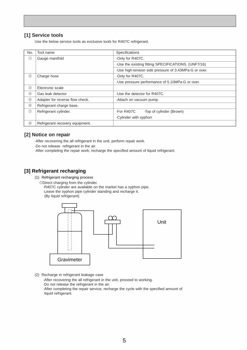
[3] Refrigerant recharging(1) Refrigerant recharging process
1Direct charging from the cylinder.·R407C cylinder are available on the market has a syphon pipe.·Leave the syphon pipe cylinder standing and recharge it.(By liquid refrigerant)
(2) Recharge in refrigerant leakage case·After recovering the all refrigerant in the unit, proceed to working.·Do not release the refrigerant in the air.·After completing the repair service, recharge the cycle with the specified amount of liquid refrigerant.
Gravimeter
Unit
[1] Service toolsUse the below service tools as exclusive tools for R407C refrigerant.
No. Tool name Specifications
1 Gauge manifold ·Only for R407C.
·Use the existing fitting SPECIFICATIONS. (UNF7/16)
·Use high-tension side pressure of 3.43MPa·G or over.
2 Charge hose ·Only for R407C.
·Use pressure performance of 5.10MPa·G or over.
3 Electronic scale
4 Gas leak detector ·Use the detector for R407C.
5 Adapter for reverse flow check. ·Attach on vacuum pump.
6 Refrigerant charge base.
7 Refrigerant cylinder. ·For R407C ·Top of cylinder (Brown)
·Cylinder with syphon
8 Refrigerant recovery equipment.
[2] Notice on repair·After recovering the all refrigerant in the unit, perform repair work.·Do not release refrigerant in the air.·After completing the repair work, recharge the specified amount of liquid refrigerant.
OC261-D--1.qxp 05.2.18 11:07 AM Page 5
6
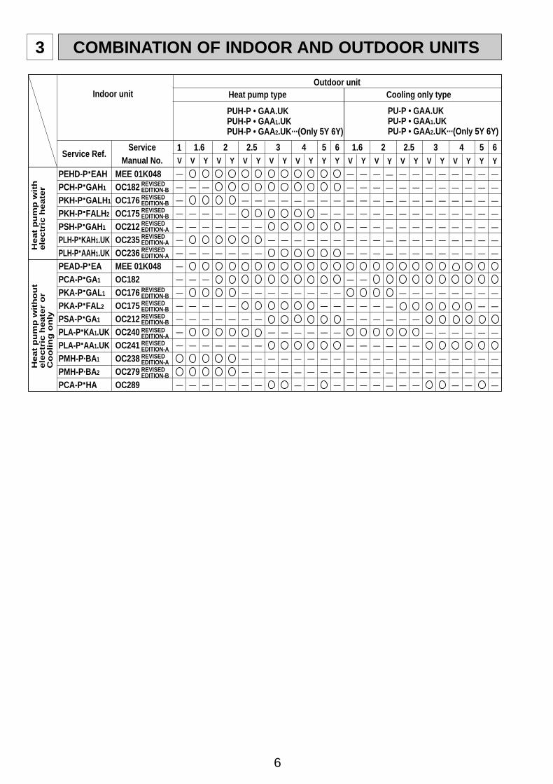
3 COMBINATION OF INDOOR AND OUTDOOR UNITS
Heat pump typeOutdoor unit
PUH-P • GAA.UKPUH-P • GAA1.UKPUH-P • GAA2.UK···(Only 5Y 6Y)
Cooling only type
PU-P • GAA.UKPU-P • GAA1.UKPU-P • GAA2.UK···(Only 5Y 6Y)
PEHD-P·EAHPCH-P·GAH1
PKH-P·GALH1
PKH-P·FALH2
PSH-P·GAH1
PLH-P·KAH1.UKPLH-P·AAH1.UKPEAD-P·EAPCA-P·GA1
PKA-P·GAL1
PKA-P·FAL2
PSA-P·GA1
PLA-P·KA1.UKPLA-P·AA1.UKPMH-P·BA1
PMH-P·BA2
PCA-P·HA
MEE 01K048OC182OC176OC175OC212OC235OC236MEE 01K048OC182OC176OC175OC212OC240OC241OC238OC279OC289
Y
—
—
—
—
—
—
—
—
—
—
—
—
—
Y
—
—
—
—
—
—
—
—
—
—
—
—
Y
—
—
—
—
—
—
—
—
—
—
—
—
Y
—
—
—
—
—
—
—
—
—
—
—
V
—
—
—
—
—
—
—
—
—
—
—
Y
—
—
—
—
—
—
—
—
—
—
—
—
—
V
—
—
—
—
—
—
—
—
—
—
—
—
—
V
—
—
—
—
—
—
—
—
—
—
—
—
—
—
Y
—
—
—
—
—
—
—
—
—
Y
—
—
—
—
—
—
—
—
Y
—
—
—
—
—
—
—
Y
—
—
—
—
—
—
V
—
—
—
—
—
—
V
—
—
—
—
—
—
—
—
—
Y
—
—
—
—
—
—
—
—
—
Y
—
—
—
—
—
—
—
V
—
—
—
—
—
—
—
V
—
—
—
—
—
—
—
—
—
Y
—
—
—
—
—
—
—
—
—
Indoor unit
1.6ServiceManual No.
Service Ref.2 2.5 3 4 5 6 1.6 2 2.5 3 4 5 6
He
at
pu
mp
wit
he
lec
tric
hea
ter
Heat
pu
mp
wit
ho
ut
ele
ctr
ic h
eate
r o
rC
oo
lin
g o
nly
REVISED EDITION-BREVISED EDITION-BREVISED EDITION-B
REVISED EDITION-B
REVISED EDITION-AREVISED EDITION-AREVISED EDITION-A
REVISED EDITION-BREVISED EDITION-B
REVISED EDITION-B
REVISED EDITION-AREVISED EDITION-AREVISED EDITION-A
1V
—
—
—
—
—
—
—
—
—
—
—
—
—
—
—
V
—
—
—
—
—
—
—
V
—
—
—
—
—
—
—
—
—
—
—
—
—
V
—
—
—
—
—
—
—
—
—
—
—
—
Y
—
—
—
—
—
—
—
—
—
—
—
—
—
—
Y
—
—
—
—
—
—
—
—
—
—
—
—
—
OC261-D--1.qxp 05.2.18 11:07 AM Page 6
7
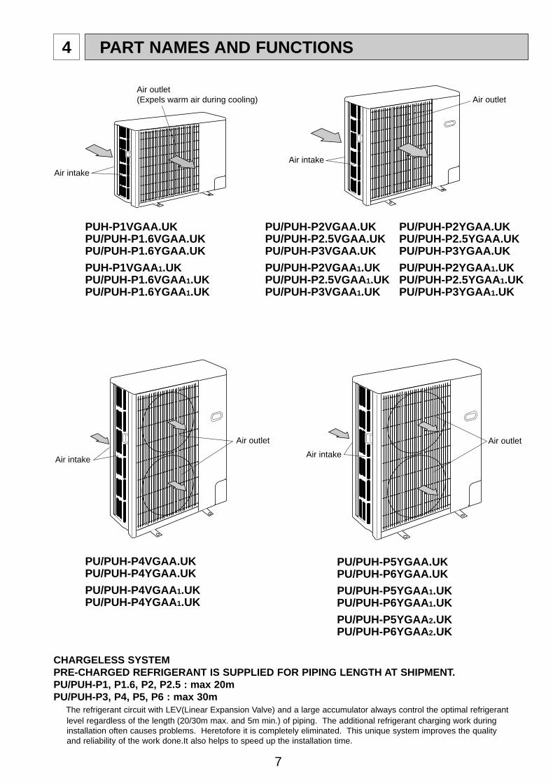
4 PART NAMES AND FUNCTIONS
CHARGELESS SYSTEMPRE-CHARGED REFRIGERANT IS SUPPLIED FOR PIPING LENGTH AT SHIPMENT.PU/PUH-P1, P1.6, P2, P2.5 : max 20mPU/PUH-P3, P4, P5, P6 : max 30m
The refrigerant circuit with LEV(Linear Expansion Valve) and a large accumulator always control the optimal refrigerantlevel regardless of the length (20/30m max. and 5m min.) of piping. The additional refrigerant charging work duringinstallation often causes problems. Heretofore it is completely eliminated. This unique system improves the qualityand reliability of the work done.It also helps to speed up the installation time.
Air intake
Air outlet(Expels warm air during cooling)
Air intake
Air outlet
Air intake
Air outlet
Air intake
Air outlet
PUH-P1VGAA.UKPU/PUH-P1.6VGAA.UKPU/PUH-P1.6YGAA.UK
PUH-P1VGAA1.UKPU/PUH-P1.6VGAA1.UKPU/PUH-P1.6YGAA1.UK
PU/PUH-P2VGAA.UK PU/PUH-P2YGAA.UKPU/PUH-P2.5VGAA.UK PU/PUH-P2.5YGAA.UKPU/PUH-P3VGAA.UK PU/PUH-P3YGAA.UK
PU/PUH-P2VGAA1.UK PU/PUH-P2YGAA 1.UKPU/PUH-P2.5VGAA1.UK PU/PUH-P2.5YGAA 1.UKPU/PUH-P3VGAA1.UK PU/PUH-P3YGAA 1.UK
PU/PUH-P4VGAA.UKPU/PUH-P4YGAA.UK
PU/PUH-P4VGAA1.UKPU/PUH-P4YGAA1.UK
PU/PUH-P5YGAA.UKPU/PUH-P6YGAA.UK
PU/PUH-P5YGAA1.UKPU/PUH-P6YGAA1.UK
PU/PUH-P5YGAA2.UKPU/PUH-P6YGAA2.UK
OC261-D--1.qxp 05.2.18 11:07 AM Page 7
8
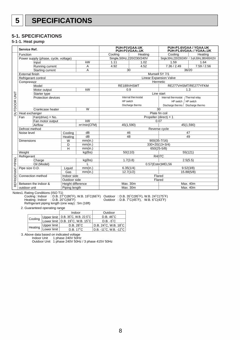
5 SPECIFICATIONS
kWAA
kW
W
kWK/min(CFM)
dBdB
mm(in.)mm(in.)mm(in.)kg(lbs)
kg(lbs)L
mm(in.)mm(in.)
FunctionPower supply (phase, cycle, voltage)
InputRunning currentStarting current
External finishRefrigerant controlCompressor
ModelMotor outputStarter typeProtection devices
Crankcase heaterHeat exchangerFan Fan(drive) o No.
Fan motor outputAirflow
Defrost methodNoise level
Dimensions
WeightRefrigerant
ChargeOil (Model)
Pipe size O.D.
Connection method
Between the indoor & outdoor unit
OU
TD
OO
R U
NIT
REF
RIG
ERAN
T PI
PIN
G
CoolingHeating
WDH
LiquidGas
Indoor sideOutdoor sideHeight differencePiping length
Notes1. Rating Conditions (ISO T1)Cooling : Indoor : D.B. 27˚C(80˚F), W.B. 19˚C(66˚F) Outdoor : D.B. 35˚C(95˚F), W.B. 24˚C(75˚F)Heating : Indoor : D.B. 20˚C(68˚F) Outdoor : D.B. 7˚C(45˚F), W.B. 6˚C(43˚F)Refrigerant piping length (one way) : 5m (16ft)
3. Above data based on indicated voltageIndoor Unit 1 phase 240V 50HzOutdoor Unit 1 phase 240V 50Hz / 3 phase 415V 50Hz
2. Guaranteed operating range
Upper limitLower limitUpper limitLower limit
IndoorD.B. 35˚C, W.B. 22.5˚CD.B. 19˚C, W.B. 15˚C
D.B. 28˚CD.B. 17˚C
OutdoorD.B. 46˚CD.B. -5˚C
D.B. 24˚C, W.B. 18˚CD.B. -11˚C, W.B. -12˚C
Cooling
Heating
Service Ref. PUH-P1VGAA.UKPUH-P1VGAA1.UK
PUH-P1.6VGAA / YGAA.UKPUH-P1.6VGAA1 / YGAA1.UK
Cooling
1.114.92
Single,50Hz,220/230/240V
30
RE189VHSMT0.9
45(1,590)
4648
50(110)
1.7(3.8)
6.35(1/4)12.7(1/2)
Max. 30mMax. 30m
Munsell 5Y 7/1Linear Expansion Valve
Hermetic
Line start
30Plate fin coil
Propeller (direct) o 10.07
Reverse cycle
900(35-7/16)330+20(13+3/4)
650(25-5/8)
R407C
0.57(Ester)MEL56
FlaredFlared
Heating
1.024.52
Cooling
1.597.36 / 2.49
Single,50Hz,220/230/240V / 3-ph,50Hz,380/400/415V
36/20
RE277VHSMT/RE277YFKM1.3
45(1,590)
4749
55(121)
2.5(5.5)
9.52(3/8)15.88(5/8)
Max. 40mMax. 40m
Heating
1.647.59 / 2.56
Internal thermostatHP switch
Discharge thermo
Thermal relay HP switch Discharge thermo
Internal thermostatHP switchDischarge thermo
5-1. SPECIFICATIONS5-1-1. Heat pump
OC261-D--1.qxp 05.2.18 11:07 AM Page 8
9
kWAA
kW
W
kWK/min(CFM)
dBdB
mm(in.)mm(in.)mm(in.)kg(lbs)
kg(lbs)L
mm(in.)mm(in.)
FunctionPower supply (phase, cycle, voltage)
InputRunning currentStarting current
External finishRefrigerant controlCompressor
ModelMotor outputStarter typeProtection devices
Crankcase heaterHeat exchangerFan Fan(drive) o No.
Fan motor outputAirflow
Defrost methodNoise level
Dimensions
WeightRefrigerant
ChargeOil (Model)
Pipe size O.D.
Connection method
Between the indoor & outdoor unit
OU
TD
OO
R U
NIT
REF
RIG
ERAN
T PI
PIN
G
CoolingHeating
WDH
LiquidGas
Indoor sideOutdoor sideHeight differencePiping length
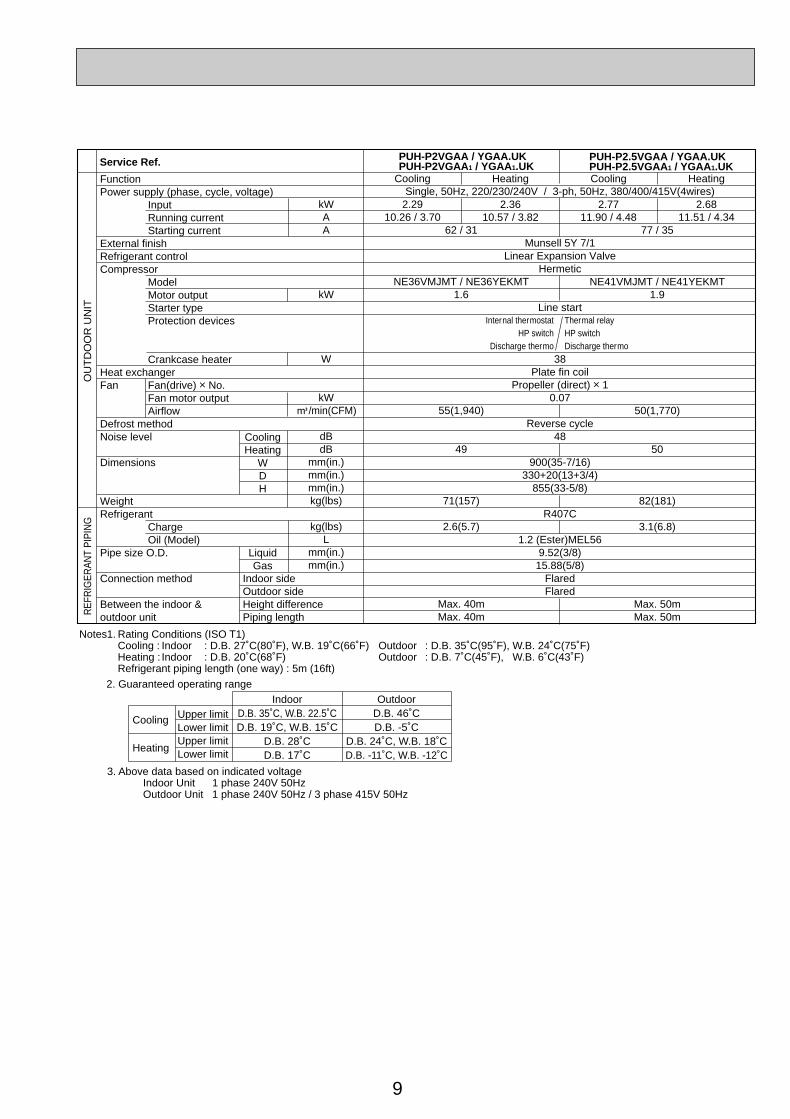
Notes1. Rating Conditions (ISO T1)Cooling : Indoor : D.B. 27˚C(80˚F), W.B. 19˚C(66˚F) Outdoor : D.B. 35˚C(95˚F), W.B. 24˚C(75˚F)Heating : Indoor : D.B. 20˚C(68˚F) Outdoor : D.B. 7˚C(45˚F), W.B. 6˚C(43˚F)Refrigerant piping length (one way) : 5m (16ft)
3. Above data based on indicated voltageIndoor Unit 1 phase 240V 50HzOutdoor Unit 1 phase 240V 50Hz / 3 phase 415V 50Hz
2. Guaranteed operating range
Upper limitLower limitUpper limitLower limit
IndoorD.B. 35˚C, W.B. 22.5˚CD.B. 19˚C, W.B. 15˚C
D.B. 28˚CD.B. 17˚C
OutdoorD.B. 46˚CD.B. -5˚C
D.B. 24˚C, W.B. 18˚CD.B. -11˚C, W.B. -12˚C
Cooling
Heating
Service Ref. PUH-P2VGAA / YGAA.UKPUH-P2VGAA1 / YGAA1.UK
PUH-P2.5VGAA / YGAA.UKPUH-P2.5VGAA1 / YGAA1.UK
Cooling
2.2910.26 / 3.70
62 / 31
NE36VMJMT / NE36YEKMT1.6
55(1,940)
49
71(157)
2.6(5.7)
Max. 40mMax. 40m
Single, 50Hz, 220/230/240V / 3-ph, 50Hz, 380/400/415V(4wires)
Munsell 5Y 7/1Linear Expansion Valve
Hermetic
Line start
38Plate fin coil
Propeller (direct) o 10.07
Reverse cycle48
900(35-7/16)330+20(13+3/4)
855(33-5/8)
R407C
1.2 (Ester)MEL569.52(3/8)15.88(5/8)
FlaredFlared
Heating
2.3610.57 / 3.82
Cooling
2.7711.90 / 4.48
77 / 35
NE41VMJMT / NE41YEKMT 1.9
50(1,770)
50
82(181)
3.1(6.8)
Max. 50mMax. 50m
Heating
2.6811.51 / 4.34
Internal thermostatHP switch
Discharge thermo
Thermal relay HP switch Discharge thermo
OC261-D--1.qxp 05.2.18 11:07 AM Page 9
10
kWAA
kW
W
kWK/min(CFM)
dBdB
mm(in.)mm(in.)mm(in.)kg(lbs)
kg(lbs)L
mm(in.)mm(in.)
FunctionPower supply (phase, cycle, voltage)
InputRunning currentStarting current
External finishRefrigerant controlCompressor
ModelMotor outputStarter typeProtection devices
Crankcase heaterHeat exchangerFan Fan(drive) o No.
Fan motor outputAirflow
Defrost methodNoise level
Dimensions
WeightRefrigerant
ChargeOil (Model)
Pipe size O.D.
Connection method
Between the indoor & outdoor unit
OU
TD
OO
R U
NIT
REF
RIG
ERAN
T PI
PIN
G
CoolingHeating
WDH
LiquidGas
Indoor sideOutdoor sideHeight differencePiping length
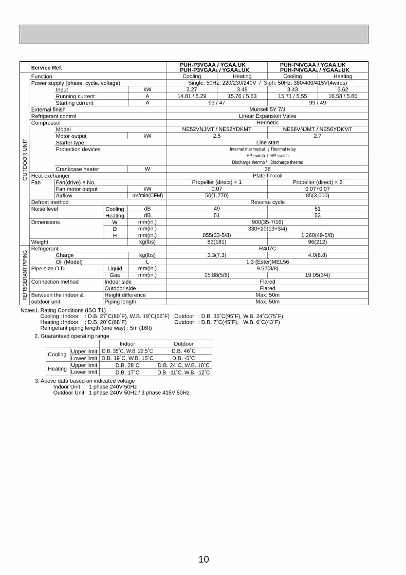
Notes1. Rating Conditions (ISO T1)Cooling : Indoor : D.B. 27˚C(80˚F), W.B. 19˚C(66˚F) Outdoor : D.B. 35˚C(95˚F), W.B. 24˚C(75˚F)Heating : Indoor : D.B. 20˚C(68˚F) Outdoor : D.B. 7˚C(45˚F), W.B. 6˚C(43˚F)Refrigerant piping length (one way) : 5m (16ft)
3. Above data based on indicated voltageIndoor Unit 1 phase 240V 50HzOutdoor Unit 1 phase 240V 50Hz / 3 phase 415V 50Hz
2. Guaranteed operating range
Upper limitLower limitUpper limitLower limit
IndoorD.B. 35˚C, W.B. 22.5˚CD.B. 19˚C, W.B. 15˚C
D.B. 28˚CD.B. 17˚C
OutdoorD.B. 46˚CD.B. -5˚C
D.B. 24˚C, W.B. 18˚CD.B. -11˚C, W.B. -12˚C
Cooling
Heating
Service Ref. PUH-P4VGAA / YGAA.UKPUH-P4VGAA1 / YGAA1.UK
PUH-P3VGAA / YGAA.UKPUH-P3VGAA1 / YGAA1.UKCooling
3.2714.81 / 5.29
93 / 47
NE52VNJMT / NE52YDKMT2.5
Propeller (direct) o 10.07
50(1,770)
4951
855(33-5/8)82(181)
3.3(7.3)
15.88(5/8)
Single, 50Hz, 220/230/240V / 3-ph, 50Hz, 380/400/415V(4wires)
Munsell 5Y 7/1Linear Expansion Valve
Hermetic
Line start
38Plate fin coil
Reverse cycle
900(35-7/16)330+20(13+3/4)
R407C
1.3 (Ester)MEL569.52(3/8)
FlaredFlared
Max. 50mMax. 50m
Heating
3.4815.76 / 5.63
Cooling
3.4315.71 / 5.55
99 / 49
NE56VNJMT / NE56YDKMT2.7
Propeller (direct) o 20.07+0.0785(3,000)
5153
1,260(49-5/8)96(212)
4.0(8.8)
19.05(3/4)
Heating
3.6216.58 / 5.86
Internal thermostatHP switch
Discharge thermo
Thermal relay HP switch Discharge thermo
OC261-D--1.qxp 05.2.18 11:07 AM Page 10

11
kWAA
kW
W
kWK/min(CFM)
dB(A)dB(A)
mm(in.)mm(in.)mm(in.)kg(lbs)
kg(lbs)L
mm(in.)mm(in.)
FunctionPower supply (phase, cycle, voltage)
InputRunning currentStarting current
External finishRefrigerant controlCompressor
Model
Motor outputStarter typeProtection devicesCrankcase heater
Heat exchangerFan Fan(drive) o No.
Fan motor outputAirflow
Defrost methodNoise level
Dimensions
WeightRefrigerant
ChargeOil (Model)
Pipe size O.D.
Connection method
Between the indoor & outdoor unit
OU
TD
OO
R U
NIT
REF
RIG
ERAN
T PI
PIN
G
CoolingHeating
WDH
LiquidGas
Indoor sideOutdoor sideHeight differencePiping length
Notes1. Rating Conditions (ISO T1)Cooling : Indoor : D.B. 27˚C(80˚F), W.B. 19˚C (66˚F) Outdoor : D.B. 35˚C(95˚F), W.B. 24˚C (75˚F)Heating : Indoor : D.B. 20˚C(68˚F) Outdoor : D.B. 7˚C(45˚F), W.B. 6˚C (43˚F)Refrigerant piping length (one way) : 5m (16ft)
3. Above data based on indicated voltageIndoor Unit 1 phase 240V 50HzOutdoor Unit 3 phase 415V 50Hz
2. Guaranteed operating range
Upper limitLower limitUpper limitLower limit
IndoorD.B. 35˚C, W.B. 22.5˚CD.B. 19˚C, W.B. 15˚C
D.B. 28˚CD.B. 17˚C
OutdoorD.B. 46˚CD.B. -5˚C
D.B. 24˚C, W.B. 18˚CD.B. -11˚C, W.B. -12˚C
Cooling
Heating
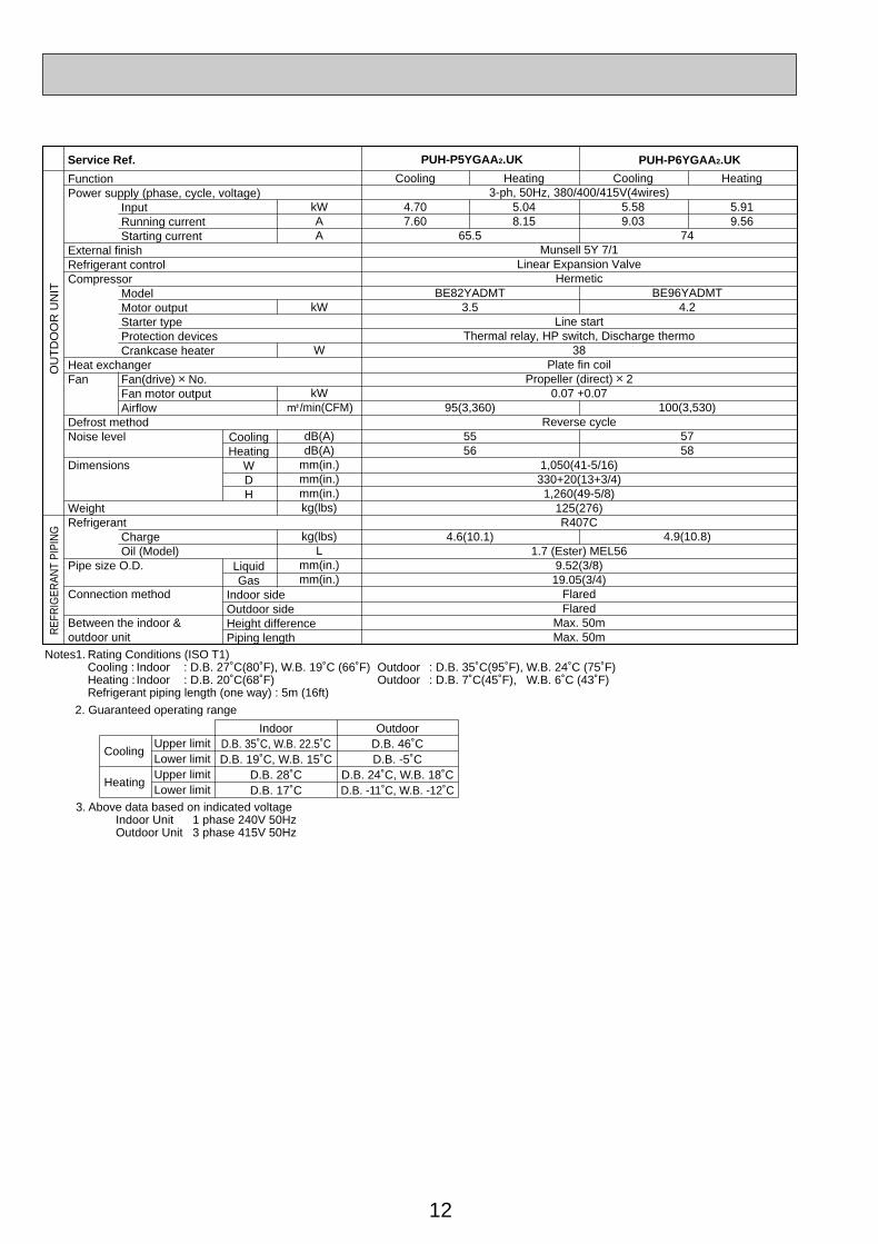
Service Ref. PUH-P5YGAA.UKPUH-P5YGAA1.UK
Cooling
5.589.03
74
ZR72KCW-TFD-522
4.2
100(3,530)
5758
4.9(10.8)1.774 (Ester) 3MAW-POE
3-ph, 50Hz, 380/400/415V(4wires)
Munsell 5Y 7/1Linear Expansion Valve
Hermetic
Line startInternal thermostat, thermal relay, HP switch, Discharge thermo
38Plate fin coil
Propeller (direct) o 20.07 +0.07
Reverse cycle
1,050(41-5/16)330+20(13+3/4)
1,260(49-5/8)122(269)R407C
9.52(3/8)19.05(3/4)
FlaredFlared
Max. 50mMax. 50m
Heating
5.919.56
Cooling
4.707.60
65.5
ZR61KCE-TFD-230 (YGAA.UK) ZR61KCW-TFD-522 (YGAA1.UK)
3.5
95(3,360)
5556
4.6(10.1)1.690 (Ester) 3MAW-POE
Heating
5.048.15
PUH-P6YGAA.UKPUH-P6YGAA1.UK
OC261-D--1.qxp 05.2.18 11:07 AM Page 11
12
kWAA
kW
W
kWK/min(CFM)
dB(A)dB(A)
mm(in.)mm(in.)mm(in.)kg(lbs)
kg(lbs)L
mm(in.)mm(in.)
FunctionPower supply (phase, cycle, voltage)
InputRunning currentStarting current
External finishRefrigerant controlCompressor
ModelMotor outputStarter typeProtection devicesCrankcase heater
Heat exchangerFan Fan(drive) o No.
Fan motor outputAirflow
Defrost methodNoise level
Dimensions
WeightRefrigerant
ChargeOil (Model)
Pipe size O.D.
Connection method
Between the indoor & outdoor unit
OU
TD
OO
R U
NIT
REF
RIG
ERAN
T PI
PIN
G
CoolingHeating
WDH
LiquidGas
Indoor sideOutdoor sideHeight differencePiping length
Notes1. Rating Conditions (ISO T1)Cooling : Indoor : D.B. 27˚C(80˚F), W.B. 19˚C (66˚F) Outdoor : D.B. 35˚C(95˚F), W.B. 24˚C (75˚F)Heating : Indoor : D.B. 20˚C(68˚F) Outdoor : D.B. 7˚C(45˚F), W.B. 6˚C (43˚F)Refrigerant piping length (one way) : 5m (16ft)
3. Above data based on indicated voltageIndoor Unit 1 phase 240V 50HzOutdoor Unit 3 phase 415V 50Hz
2. Guaranteed operating range
Upper limitLower limitUpper limitLower limit
IndoorD.B. 35˚C, W.B. 22.5˚CD.B. 19˚C, W.B. 15˚C
D.B. 28˚CD.B. 17˚C
OutdoorD.B. 46˚CD.B. -5˚C
D.B. 24˚C, W.B. 18˚CD.B. -11˚C, W.B. -12˚C
Cooling
Heating
Service Ref. PUH-P5YGAA2.UK
Cooling
5.589.03
74
BE96YADMT4.2
100(3,530)
5758
4.9(10.8)
3-ph, 50Hz, 380/400/415V(4wires)
Munsell 5Y 7/1Linear Expansion Valve
Hermetic
Line startThermal relay, HP switch, Discharge thermo
38Plate fin coil
Propeller (direct) o 20.07 +0.07
Reverse cycle
1,050(41-5/16)330+20(13+3/4)
1,260(49-5/8)125(276)R407C
1.7 (Ester) MEL569.52(3/8)19.05(3/4)
FlaredFlared
Max. 50mMax. 50m
Heating
5.919.56
Cooling
4.707.60
65.5
BE82YADMT3.5
95(3,360)
5556
4.6(10.1)
Heating
5.048.15
PUH-P6YGAA2.UK
OC261-D--1.qxp 05.2.18 11:07 AM Page 12
13
kWAA
kW
W
kWK/min(CFM)
dBmm(in.)mm(in.)mm(in.)kg(lbs)
kg(lbs)L
mm(in.)mm(in.)
FunctionPower supply (phase, cycle, voltage)
InputRunning currentStarting current
External finishRefrigerant controlCompressor
ModelMotor outputStarter typeProtection devicesCrankcase heater
Heat exchangerFan Fan(drive) o No.
Fan motor outputAirflow
Defrost methodNoise level
Dimensions
WeightRefrigerant
ChargeOil (Model)
Pipe size O.D.
Connection method
Between the indoor & outdoor unit
OU
TD
OO
R U
NIT
REF
RIG
ERAN
T PI
PIN
G
CoolingWDH
LiquidGas
Indoor sideOutdoor sideHeight differencePiping length
Notes1. Rating Conditions (ISO T1)Cooling : Indoor : D.B. 27˚C(80˚F), W.B. 19˚C (66˚F) Outdoor : D.B. 35˚C(95˚F), W.B. 24˚C (75˚F)Refrigerant piping length (one way) : 5m (16ft)
3. Above data based on indicated voltageIndoor Unit 1 phase 240V 50HzOutdoor Unit 1 phase 240V 50Hz / 3phase 415V 50Hz
2. Guaranteed operating range
Upper limitLower limit
IndoorD.B. 35˚C, W.B. 22.5˚CD.B. 19˚C, W.B. 15˚C
OutdoorD.B. 46˚CD.B. -5˚C
Cooling
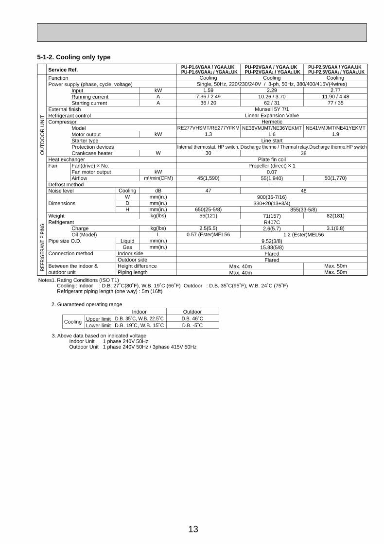
Service Ref. PU-P1.6VGAA / YGAA.UKPU-P1.6VGAA1 / YGAA1.UK
PU-P2VGAA / YGAA.UKPU-P2VGAA1 / YGAA1.UK
PU-P2.5VGAA / YGAA.UKPU-P2.5VGAA1 / YGAA1.UK
Cooling
1.597.36 / 2.49
36 / 20
RE277VHSMT/RE277YFKM1.3
30
45(1,590)
47
650(25-5/8)55(121)
2.5(5.5)0.57 (Ester)MEL56
Single, 50Hz, 220/230/240V / 3-ph, 50Hz, 380/400/415V(4wires)2.29
10.26 / 3.7062 / 31
Munsell 5Y 7/1Linear Expansion Valve
HermeticNE36VMJMT/NE36YEKMT
1.6Line start
Internal thermostat, HP switch, Discharge thermo / Thermal relay,Discharge thermo,HP switch
Plate fin coilPropeller (direct) o 1
0.0755(1,940)
—
900(35-7/16)330+20(13+3/4)
71(157)R407C2.6(5.7)
9.52(3/8)15.88(5/8)
FlaredFlared
Cooling
38
48
855(33-5/8)
1.2 (Ester)MEL56
2.7711.90 / 4.48
77 / 35
NE41VMJMT/NE41YEKMT1.9
50(1,770)
82(181)
3.1(6.8)
Max. 50mMax. 50m
Cooling
Max. 40mMax. 40m
5-1-2. Cooling only type
OC261-D--1.qxp 05.2.18 11:07 AM Page 13
14
kWAA
kW
W
kWK/min(CFM)
dBmm(in.)mm(in.)mm(in.)kg(lbs)
kg(lbs)L
mm(in.)mm(in.)
FunctionPower supply (phase, cycle, voltage)
InputRunning currentStarting current
External finishRefrigerant controlCompressor
ModelMotor outputStarter typeProtection devices
Crankcase heaterHeat exchangerFan Fan(drive) o No.
Fan motor outputAirflow
Defrost methodNoise levelDimensions
WeightRefrigerant
ChargeOil (Model)
Pipe size O.D.
Connection method
Between the indoor & outdoor unit
OU
TD
OO
R U
NIT
REF
RIG
ERAN
T PI
PIN
G
CoolingWDH
LiquidGas
Indoor sideOutdoor sideHeight differencePiping length
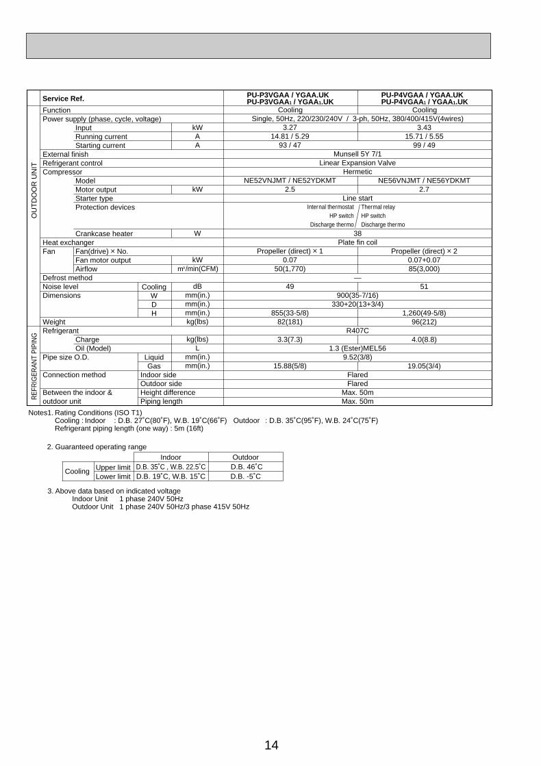
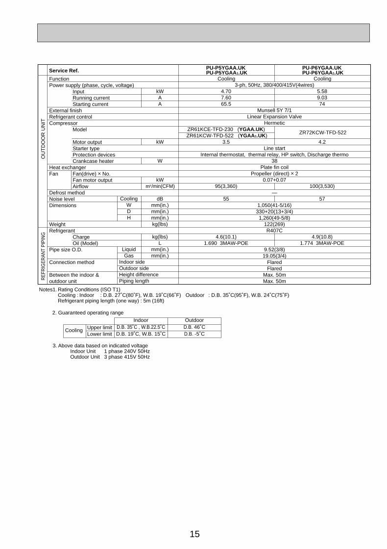
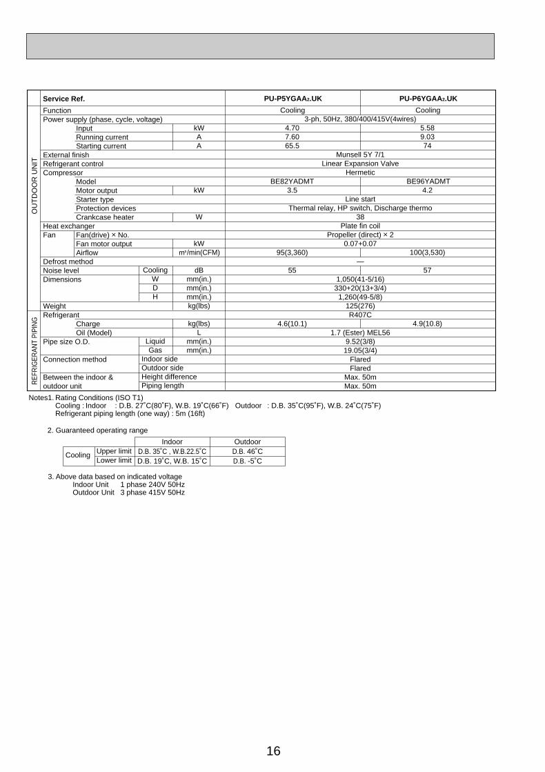
Notes1. Rating Conditions (ISO T1)Cooling : Indoor : D.B. 27˚C(80˚F), W.B. 19˚C(66˚F) Outdoor : D.B. 35˚C(95˚F), W.B. 24˚C(75˚F)Refrigerant piping length (one way) : 5m (16ft)
3. Above data based on indicated voltageIndoor Unit 1 phase 240V 50HzOutdoor Unit 1 phase 240V 50Hz/3 phase 415V 50Hz
2. Guaranteed operating range
Upper limitLower limit
IndoorD.B. 35˚C , W.B. 22.5˚CD.B. 19˚C, W.B. 15˚C
Outdoor D.B. 46˚CD.B. -5˚C
Cooling
Service Ref. PU-P3VGAA / YGAA.UKPU-P3VGAA1 / YGAA1.UK
PU-P4VGAA / YGAA.UKPU-P4VGAA1 / YGAA1.UK
Cooling
3.2714.81 / 5.29
93 / 47
NE52VNJMT / NE52YDKMT2.5
Propeller (direct) o 10.07
50(1,770)
49
855(33-5/8)82(181)
3.3(7.3)
15.88(5/8)
Single, 50Hz, 220/230/240V / 3-ph, 50Hz, 380/400/415V(4wires)
Munsell 5Y 7/1Linear Expansion Valve
Hermetic
Line start
38Plate fin coil
—
900(35-7/16)330+20(13+3/4)
R407C
1.3 (Ester)MEL569.52(3/8)
FlaredFlared
Max. 50mMax. 50m
Cooling
3.4315.71 / 5.55
99 / 49
NE56VNJMT / NE56YDKMT2.7
Propeller (direct) o 20.07+0.0785(3,000)
51
1,260(49-5/8)96(212)
4.0(8.8)
19.05(3/4)
Internal thermostatHP switch
Discharge thermo
Thermal relay HP switch Discharge thermo
OC261-D--1.qxp 05.2.18 11:07 AM Page 14
15
kWAA
kW
W
kWK/min(CFM)
dBmm(in.)mm(in.)mm(in.)kg(lbs)
kg(lbs)L
mm(in.)mm(in.)
FunctionPower supply (phase, cycle, voltage)
InputRunning currentStarting current
External finishRefrigerant controlCompressor
Model
Motor outputStarter typeProtection devicesCrankcase heater
Heat exchangerFan Fan(drive) o No.
Fan motor outputAirflow
Defrost methodNoise levelDimensions
WeightRefrigerant
ChargeOil (Model)
Pipe size O.D.
Connection method
Between the indoor & outdoor unit
OU
TD
OO
R U
NIT
REF
RIG
ERAN
T PI
PIN
G
CoolingWDH
LiquidGas
Indoor sideOutdoor sideHeight differencePiping length
Notes1. Rating Conditions (ISO T1)Cooling : Indoor : D.B. 27˚C(80˚F), W.B. 19˚C(66˚F) Outdoor : D.B. 35˚C(95˚F), W.B. 24˚C(75˚F)Refrigerant piping length (one way) : 5m (16ft)
3. Above data based on indicated voltageIndoor Unit 1 phase 240V 50HzOutdoor Unit 3 phase 415V 50Hz
2. Guaranteed operating range
Upper limitLower limit
IndoorD.B. 35˚C , W.B.22.5˚CD.B. 19˚C, W.B. 15˚C
OutdoorD.B. 46˚CD.B. -5˚C
Cooling
Service Ref. PU-P5YGAA.UKPU-P5YGAA1.UK
PU-P6YGAA.UKPU-P6YGAA1.UK
Cooling
5.589.0374
ZR72KCW-TFD-522
4.2
100(3,530)
57
4.9(10.8)1.774 3MAW-POE
3-ph, 50Hz, 380/400/415V(4wires)
Munsell 5Y 7/1Linear Expansion Valve
Hermetic
Line startInternal thermostat, thermal relay, HP switch, Discharge thermo
38Plate fin coil
Propeller (direct) o 20.07+0.07
—
1,050(41-5/16)330+20(13+3/4)
1,260(49-5/8)122(269)R407C
9.52(3/8)19.05(3/4)
FlaredFlared
Max. 50mMax. 50m
Cooling
4.707.6065.5
ZR61KCE-TFD-230 (YGAA.UK) ZR61KCW-TFD-522 (YGAA1.UK)
3.5
95(3,360)
55
4.6(10.1)1.690 3MAW-POE
OC261-D--1.qxp 05.2.18 11:07 AM Page 15
16
kWAA
kW
W
kWK/min(CFM)
dBmm(in.)mm(in.)mm(in.)kg(lbs)
kg(lbs)L
mm(in.)mm(in.)
FunctionPower supply (phase, cycle, voltage)
InputRunning currentStarting current
External finishRefrigerant controlCompressor
ModelMotor outputStarter typeProtection devicesCrankcase heater
Heat exchangerFan Fan(drive) o No.
Fan motor outputAirflow
Defrost methodNoise levelDimensions
WeightRefrigerant
ChargeOil (Model)
Pipe size O.D.
Connection method
Between the indoor & outdoor unit
OU
TD
OO
R U
NIT
REF
RIG
ERAN
T PI
PIN
G
CoolingWDH
LiquidGas
Indoor sideOutdoor sideHeight differencePiping length
Notes1. Rating Conditions (ISO T1)Cooling : Indoor : D.B. 27˚C(80˚F), W.B. 19˚C(66˚F) Outdoor : D.B. 35˚C(95˚F), W.B. 24˚C(75˚F)Refrigerant piping length (one way) : 5m (16ft)
3. Above data based on indicated voltageIndoor Unit 1 phase 240V 50HzOutdoor Unit 3 phase 415V 50Hz
2. Guaranteed operating range
Upper limitLower limit
IndoorD.B. 35˚C , W.B.22.5˚CD.B. 19˚C, W.B. 15˚C
OutdoorD.B. 46˚CD.B. -5˚C
Cooling
Service Ref. PU-P5YGAA2.UK PU-P6YGAA2.UK
Cooling
5.589.0374
BE96YADMT4.2
100(3,530)
57
4.9(10.8)
3-ph, 50Hz, 380/400/415V(4wires)
Munsell 5Y 7/1Linear Expansion Valve
Hermetic
Line startThermal relay, HP switch, Discharge thermo
38Plate fin coil
Propeller (direct) o 20.07+0.07
—
1,050(41-5/16)330+20(13+3/4)
1,260(49-5/8)125(276)R407C
1.7 (Ester) MEL569.52(3/8)19.05(3/4)
FlaredFlared
Max. 50mMax. 50m
Cooling
4.707.6065.5
BE82YADMT3.5
95(3,360)
55
4.6(10.1)
OC261-D--1.qxp 05.2.18 11:07 AM Page 16
17
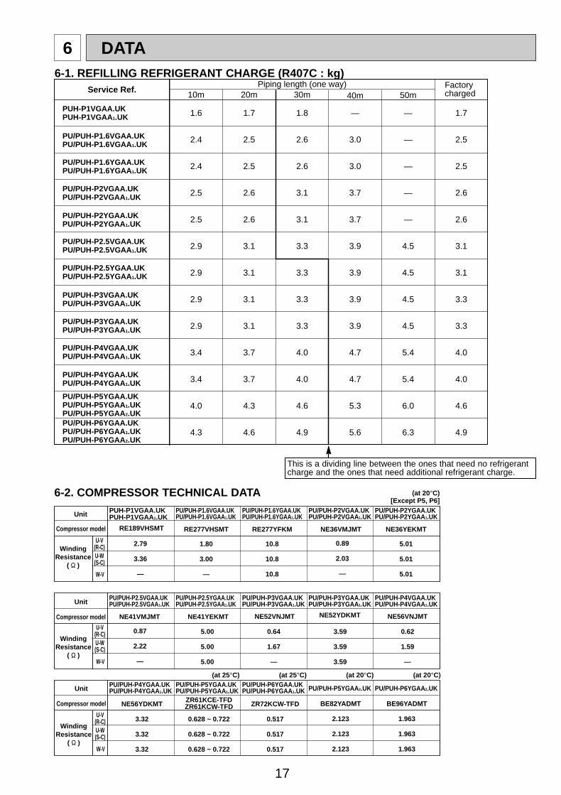
6 DATA6-1. REFILLING REFRIGERANT CHARGE (R407C : kg)
Piping length (one way)10m 20m 30m 40m 50m
Factorycharged
1.6
2.4
2.4
2.5
2.5
2.9
2.9
2.9
2.9
3.4
3.4
4.0
4.3
1.7
2.5
2.5
2.6
2.6
3.1
3.1
3.1
3.1
3.7
3.7
4.3
4.6
1.8
2.6
2.6
3.1
3.1
3.3
3.3
3.3
3.3
4.0
4.0
4.6
4.9
—
3.0
3.0
3.7
3.7
3.9
3.9
3.9
3.9
4.7
4.7
5.3
5.6
—
—
—
—
—
4.5
4.5
4.5
4.5
5.4
5.4
6.0
6.3
1.7
2.5
2.5
2.6
2.6
3.1
3.1
3.3
3.3
4.0
4.0
4.6
4.9
Service Ref.
PU/PUH-P6YGAA.UKPU/PUH-P6YGAA1.UKPU/PUH-P6YGAA2.UK
PU/PUH-P5YGAA.UKPU/PUH-P5YGAA1.UKPU/PUH-P5YGAA2.UK
PU/PUH-P4VGAA.UKPU/PUH-P4VGAA1.UK
PU/PUH-P4YGAA.UKPU/PUH-P4YGAA1.UK
PU/PUH-P3YGAA.UKPU/PUH-P3YGAA1.UK
PU/PUH-P3VGAA.UKPU/PUH-P3VGAA1.UK
PU/PUH-P2.5YGAA.UKPU/PUH-P2.5YGAA1.UK
PU/PUH-P2.5VGAA.UKPU/PUH-P2.5VGAA1.UK
PU/PUH-P2YGAA.UKPU/PUH-P2YGAA1.UK
PU/PUH-P2VGAA.UKPU/PUH-P2VGAA1.UK
PU/PUH-P1.6YGAA.UKPU/PUH-P1.6YGAA1.UK
PU/PUH-P1.6VGAA.UKPU/PUH-P1.6VGAA1.UK
PUH-P1VGAA.UKPUH-P1VGAA1.UK
This is a dividing line between the ones that need no refrigerantcharge and the ones that need additional refrigerant charge.
6-2. COMPRESSOR TECHNICAL DATA
Compressor model
WindingResistance
( " )
U-V(R-C)U-W(S-C)
W-V
U-V(R-C)U-W(S-C)
W-V
RE277VHSMT RE277YFKM
Unit
NE36VMJMT
1.80
3.00
—
10.8
10.8
10.8
5.01
5.01
5.01
NE36YEKMT
0.89
2.03
—
Unit
Compressor model
WindingResistance
( " )
(at 25°C) (at 20°C) (at 20°C)(at 25°C)
(at 20°C)[Except P5, P6]
BE96YADMTBE82YADMT
2.123
2.123
2.123
NE52VNJMT
0.64
1.67
—
3.59
3.59
3.59
1.963
1.963
1.963
ZR61KCE-TFDZR61KCW-TFD ZR72KCW-TFD
0.628 ~ 0.722
0.628 ~ 0.722
0.628 ~ 0.722
0.517
0.517
0.517
NE56YDKMT
3.32
3.32
3.32
PU/PUH-P1.6VGAA.UKPU/PUH-P1.6VGAA1.UK
PU/PUH-P1.6YGAA.UKPU/PUH-P1.6YGAA1.UK
PU/PUH-P2VGAA.UKPU/PUH-P2VGAA1.UK
PU/PUH-P2YGAA.UKPU/PUH-P2YGAA1.UK
PUH-P1VGAA.UKPUH-P1VGAA1.UK
PU/PUH-P2.5YGAA.UKPU/PUH-P2.5YGAA1.UK
PU/PUH-P2.5VGAA.UKPU/PUH-P2.5VGAA1.UK
PU/PUH-P3VGAA.UKPU/PUH-P3VGAA1.UK
PU/PUH-P4VGAA.UKPU/PUH-P4VGAA1.UK
PU/PUH-P3YGAA.UKPU/PUH-P3YGAA1.UK
PU/PUH-P5YGAA2.UK PU/PUH-P6YGAA2.UKPU/PUH-P6YGAA.UKPU/PUH-P6YGAA1.UK
PU/PUH-P4YGAA.UKPU/PUH-P4YGAA1.UK
PU/PUH-P5YGAA.UKPU/PUH-P5YGAA1.UK
U-V(R-C)U-W(S-C)
W-V
Unit
Compressor model
WindingResistance
( " )
NE41VMJMT NE41YEKMT
5.00
5.00
5.00
NE56VNJMT
0.62
1.59
—
RE189VHSMT
2.79
3.36
—
0.87
2.22
—
NE52YDKMT
OC261-D--1.qxp 05.2.18 11:07 AM Page 17
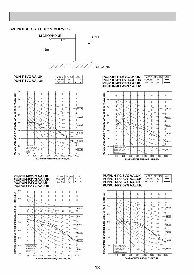
18
1m
1mMICROPHONE UNIT
GROUND
90
80
70
60
50
40
30
20
1063 125 250 500 1000 2000 4000 8000
APPROXIMATETHRESHOLD OFHEARING FORCONTINUOUSNOISE
NC-60
NC-50
NC-40
NC-30
NC-20
NC-70
OC
TAV
E B
AN
D S
OU
ND
PR
ES
SU
RE
LE
VE
L, d
B (0
dB
= 0
.000
2 µb
ar)
BAND CENTER FREQUENCIES, Hz
PU/PUH-P1.6VGAA.UKPU/PUH-P1.6VGAA1.UKPU/PUH-P1.6YGAA.UKPU/PUH-P1.6YGAA1.UK
COOLINGMODE
HEATING47
SPL(dB)
49
LINE
6-3. NOISE CRITERION CURVES
90
80
70
60
50
40
30
20
1063 125 250 500 1000 2000 4000 8000
APPROXIMATETHRESHOLD OFHEARING FORCONTINUOUSNOISE
NC-60
NC-50
NC-40
NC-30
NC-20
NC-70
OC
TAV
E B
AN
D S
OU
ND
PR
ES
SU
RE
LE
VE
L, d
B (0
dB
= 0
.000
2 µb
ar)
BAND CENTER FREQUENCIES, Hz
COOLINGMODE
HEATING
SPL(dB) LINEPU/PUH-P2VGAA.UKPU/PUH-P2VGAA1.UKPU/PUH-P2YGAA.UKPU/PUH-P2YGAA1.UK
4849
90
80
70
60
50
40
30
20
10OC
TAV
E B
AN
D S
OU
ND
PR
ES
SU
RE
LE
VE
L, d
B (0
dB
= 0
.000
2 µb
ar)
63 125 250 500 1000 2000 4000 8000
BAND CENTER FREQUENCIES, Hz
APPROXIMATETHRESHOLD OFHEARING FORCONTINUOUSNOISE
NC-60
NC-50
NC-40
NC-30
NC-20
NC-70
COOLINGMODE
HEATING
SPL(dB) LINEPU/PUH-P2.5VGAA.UKPU/PUH-P2.5VGAA1.UKPU/PUH-P2.5YGAA.UKPU/PUH-P2.5YGAA1.UK
4850
90
80
70
60
50
40
30
20
1063 125 250 500 1000 2000 4000 8000
APPROXIMATETHRESHOLD OFHEARING FORCONTINUOUSNOISE
NC-60
NC-50
NC-40
NC-30
NC-20
NC-70
OC
TAV
E B
AN
D S
OU
ND
PR
ES
SU
RE
LE
VE
L, d
B (0
dB
= 0
.000
2 µb
ar)
BAND CENTER FREQUENCIES, Hz
PUH-P1VGAA.UKPUH-P1VGAA1.UK COOLING
MODE
HEATING46
SPL(dB)
48
LINE
OC261-D--1.qxp 05.2.18 11:07 AM Page 18
19
90
80
70
60
50
40
30
20
1063 125 250 500 1000 2000 4000 8000
APPROXIMATETHRESHOLD OFHEARING FORCONTINUOUSNOISE
NC-60
NC-50
NC-40
NC-30
NC-20
NC-70
OC
TAV
E B
AN
D S
OU
ND
PR
ES
SU
RE
LE
VE
L, d
B (0
dB
= 0
.000
2 µb
ar)
BAND CENTER FREQUENCIES, Hz
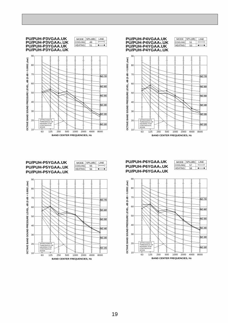
COOLINGMODE
HEATING
SPL(dB) LINE5556
PU/PUH-P5YGAA.UKPU/PUH-P5YGAA1.UKPU/PUH-P5YGAA2.UK
90
80
70
60
50
40
30
20
1063 125 250 500 1000 2000 4000 8000
APPROXIMATETHRESHOLD OFHEARING FORCONTINUOUSNOISE
NC-60
NC-50
NC-40
NC-30
NC-20
NC-70
OC
TAV
E B
AN
D S
OU
ND
PR
ES
SU
RE
LE
VE
L, d
B (0
dB
= 0
.000
2 µb
ar)
BAND CENTER FREQUENCIES, Hz
COOLINGMODE
HEATING
SPL(dB) LINE5758
PU/PUH-P6YGAA.UKPU/PUH-P6YGAA1.UKPU/PUH-P6YGAA2.UK
90
80
70
60
50
40
30
20
1063 125 250 500 1000 2000 4000 8000
APPROXIMATETHRESHOLD OFHEARING FORCONTINUOUSNOISE
NC-60
NC-50
NC-40
NC-30
NC-20
NC-70
OC
TAV
E B
AN
D S
OU
ND
PR
ES
SU
RE
LE
VE
L, d
B (0
dB
= 0
.000
2 µb
ar)
BAND CENTER FREQUENCIES, Hz
COOLINGMODE
HEATING
SPL(dB) LINE5153
PU/PUH-P4VGAA.UKPU/PUH-P4VGAA1.UKPU/PUH-P4YGAA.UKPU/PUH-P4YGAA1.UK
90
80
70
60
50
40
30
20
1063 125 250 500 1000 2000 4000 8000
APPROXIMATETHRESHOLD OFHEARING FORCONTINUOUSNOISE
NC-60
NC-50
NC-40
NC-30
NC-20
NC-70
OC
TAV
E B
AN
D S
OU
ND
PR
ES
SU
RE
LE
VE
L, d
B (0
dB
= 0
.000
2 µb
ar)
BAND CENTER FREQUENCIES, Hz
COOLINGMODE
HEATING
SPL(dB) LINE4951
PU/PUH-P3VGAA.UKPU/PUH-P3VGAA1.UKPU/PUH-P3YGAA.UKPU/PUH-P3YGAA1.UK
OC261-D--1.qxp 05.2.18 11:07 AM Page 19
20
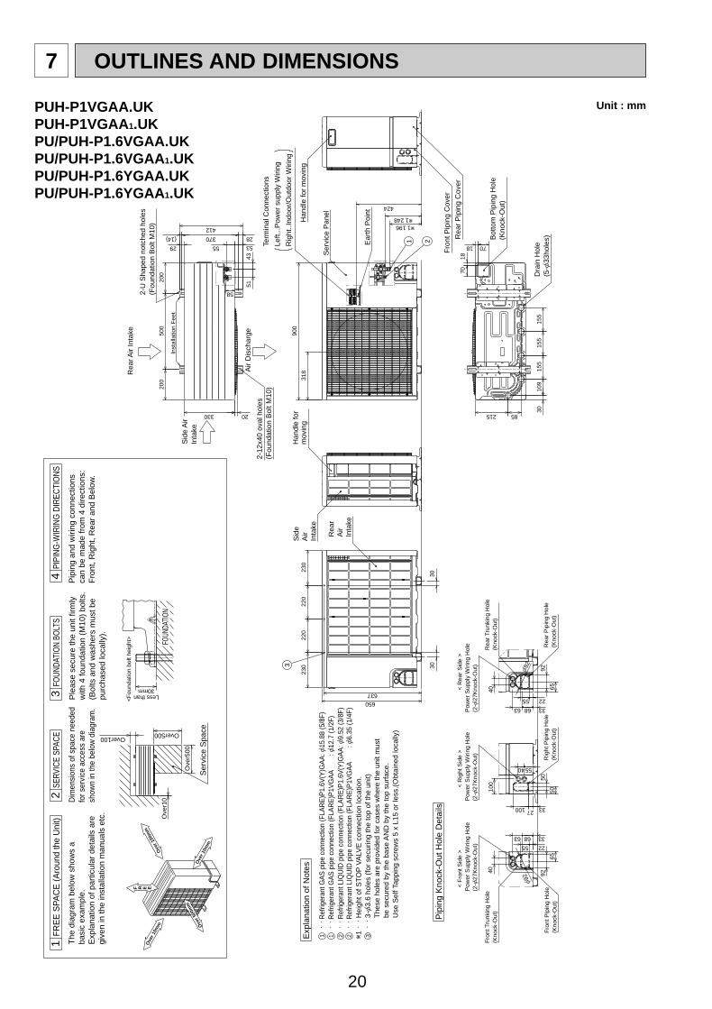
7 OUTLINES AND DIMENSIONS
PUH-P1VGAA.UKPUH-P1VGAA1.UKPU/PUH-P1.6VGAA.UKPU/PUH-P1.6VGAA1.UKPU/PUH-P1.6YGAA.UKPU/PUH-P1.6YGAA1.UK
32
1T
SR
w1 248w1 196
500
Pow
er S
uppl
y W
iring
Hol
e(2
-[27
Kno
ck-O
ut)
Rig
ht P
ipin
g H
ole
(Kno
ck-O
ut)
Pow
er S
uppl
y W
iring
Hol
e(2
-[27
Kno
ck-O
ut)
Term
inal
Con
nect
ions
Left.
..Pow
er s
uppl
y W
iring
Rig
ht..I
ndoo
r/O
utdo
or W
iring
70
70
155
155
155
109
30215 85
Bot
tom
Pip
ing
Hol
e(K
nock
-Out
)
Dra
in H
ole
(5-[
33ho
les)
18
18
424
900
318
Han
dle
for
mov
ing
Ear
th P
oint
Ser
vice
Pan
el
Fro
nt P
ipin
g C
over
Rea
r P
ipin
g C
over
1 2
Sid
e A
irIn
take
200
200
53
370(14)
412
29
330
55
4351
Rea
r Air
Inta
ke
Air
Dis
char
ge
2-U
Sha
ped
notc
hed
hole
s(F
ound
atio
n B
olt M
10)
2-12
x40
oval
hol
es(F
ound
atio
n B
olt M
10)
20
28
58
Inst
alla
tion
Fee
t
Rea
rA
irIn
take
Sid
eA
irIn
take
Han
dle
for
mov
ing
3
230
220
220
230
637650
3030
Rea
r Tr
unki
ng H
ole
(Kno
ck-O
ut)
< R
ear
Sid
e >
Pow
er S
uppl
y W
iring
Hol
e(2
-[27
Kno
ck-O
ut)
40
33
2255
6863
65
92R
ear
Pip
ing
Hol
e(K
nock
-Out
)
[92
Pip
ing
Kno
ck-O
ut H
ole
Det
ails
. .
Ref
riger
ant G
AS
pip
e co
nnec
tion
(FLA
RE
)P1.
6V(Y
)GA
A: [
15.8
8 (5
/8F)
. .
Ref
riger
ant L
IQU
ID p
ipe
conn
ectio
n (F
LAR
E)P
1.6V
(Y)G
AA
: [9.
52 (3
/8F)
. .
Hei
ght o
f ST
OP
VA
LVE
con
nect
ion
loca
tion.
1 2
Fro
nt T
runk
ing
Hol
e(K
nock
-Out
)
< R
ight
Sid
e >
< F
ront
Sid
e >
Exp
lana
tion
of N
otes 40
6863
2255
65
92
3327100
50
50
100
33
[92
Fro
nt P
ipin
g H
ole
(Kno
ck-O
ut)
5540
3 .
. 3-[
3.6
hole
s (f
or s
ecur
ing
the
top
of th
e un
it)
T
hese
hol
es a
re p
rovi
ded
for
case
s w
here
the
unit
mus
t
be
sec
ured
by
the
base
AN
D b
y th
e to
p su
rfac
e.
U
se S
elf T
appi
ng s
crew
s 5
x L1
5 or
less
.(O
btai
ned
loca
lly)
w1
. .
Ref
riger
ant G
AS
pip
e co
nnec
tion
(FLA
RE
)P1V
GA
A
: [
12.7
(1/2
F)
. .
Ref
riger
ant L
IQU
ID p
ipe
conn
ectio
n (F
LAR
E)P
1VG
AA
: [
6.35
(1/4
F)
1 2
Ove
r 10m
m
F R E E
Ove
r 500
mm
Less than30mm
FR
EE
SPA
CE
(A
roun
d th
e U
nit)
Pip
ing
and
wiri
ng c
onne
ctio
nsca
n be
mad
e fr
om 4
dire
ctio
ns:
Fro
nt, R
ight
, Rea
r an
d B
elow
.
FOUN
DATI
ON
BOLT
S1 T
he d
iagr
am b
elow
sho
ws
aba
sic
exam
ple.
Exp
lana
tion
of p
artic
ular
det
ails
are
give
n in
the
inst
alla
tion
man
uals
etc
.
SERV
ICE
SPAC
E
Dim
ensi
ons
of s
pace
nee
ded
for s
ervi
ce a
cces
s ar
esh
own
in th
e be
low
dia
gram
.
2
Ove
r500
Over500
PIPI
NG
-WIR
ING
DIR
ECTI
ON
S4
3
FOUN
DATI
ON
<F
ound
atio
n bo
lt he
ight
>
Ple
ase
secu
re th
e un
it fir
mly
with
4 fo
unda
tion
(M10
) bo
lts.
(Bol
ts a
nd w
ashe
rs m
ust b
epu
rcha
sed
loca
lly).
Ser
vice
Spa
ce
Ove
r 100
mm
Ove
r 10m
m
Ove
r10
Over100
Unit : mm
OC261-D--1.qxp 05.2.18 11:07 AM Page 20
21
32
1T
SR
w1 376w1 428
Han
dle
Rea
rA
irIn
take
Sid
eA
irIn
take
Inst
alla
tion
Fee
t
2-U
Sha
ped
notc
hed
hole
s(F
ound
atio
n B
olt M
10)
Sid
e A
irIn
take
Rea
r Air
Inta
ke
Air
Dis
char
ge
2-12
x40
oval
hol
es(F
ound
atio
n B
olt M
10)
Term
inal
Con
nect
ions
Left.
..Pow
er s
uppl
y W
iring
Rig
ht..I
ndoo
r/O
utdo
or W
iring
Ear
th P
oint
Ser
vice
Pan
el
Rea
r P
ipin
g C
over
Fro
nt P
ipin
g C
over
Bot
tom
Pip
ing
Hol
e(K
nock
-Out
)
Dra
in H
ole
(5-[
33ho
les)
Pow
er S
uppl
y W
iring
Hol
e(2
-[27
Kno
ck-O
ut)
Rea
r P
ipin
g H
ole
(Kno
ck-O
ut)
< R
ear
Sid
e >
Rea
r Tr
unki
ng H
ole
(Kno
ck-O
ut)
40
33
2255
6863
65
92[92
Pip
ing
Kno
ck-O
ut H
ole
Det
ails
Fro
nt P
ipin
g H
ole
(Kno
ck-O
ut)
Fro
nt T
runk
ing
Hol
e(K
nock
-Out
)
Pow
er S
uppl
y W
iring
Hol
e(2
-[27
Kno
ck-O
ut)
Pow
er S
uppl
y W
iring
Hol
e(2
-[27
Kno
ck-O
ut)
< F
ront
Sid
e >
Rig
ht P
ipin
g H
ole
(Kno
ck-O
ut)
< R
ight
Sid
e >
40
6863
2255
65
92
3327100
50
50
100
33
[92
5540
70
70
155
155
155
109
30215 8518
18
627
442
900
318
Han
dle
1 2
200
500
200
53370(14)
412
29
330
55
4351
20
28
58
Han
dle
3
230
220
220
230
840
855
3030
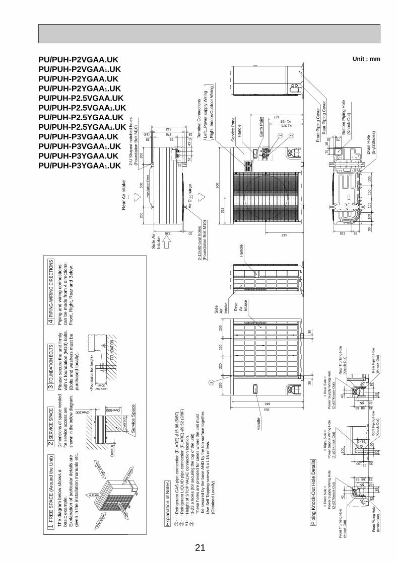
. . .
Ref
riger
ant G
AS
pip
e co
nnec
tion
(FLA
RE
) [
15.8
8 (5
/8F
). .
. R
efrig
eran
t LIQ
UID
pip
e co
nnec
tion
(FLA
RE
) [
9.52
(3/
8F)
. . .
Hei
ght o
f ST
OP
VA
LVE
con
nect
ion
loca
tion.
. . .
3-[
3.6
hole
s (f
or s
ecur
ing
the
top
of th
e un
it)
T
hese
hol
es a
re p
rovi
ded
for
case
s w
here
the
unit
mus
t
b
e se
cure
d by
the
base
AN
D b
y th
e to
p su
rfac
e to
geth
er.
Use
Sel
f Tap
ping
scr
ews
5 x
L15
or le
ss.
(Obt
aine
d Lo
cally
)
Exp
lana
tion
of N
otes
1 w12 3
Ove
r10
Over100
Ove
r500
Over500
Ser
vice
Spa
ce
Less than
<F
ound
atio
n bo
lt he
ight
>
30mm
The
dia
gram
bel
ow s
how
s a
basi
c ex
ampl
e.E
xpla
natio
n of
par
ticul
ar d
etai
ls a
regi
ven
in th
e in
stal
latio
n m
anua
ls e
tc.
Ple
ase
secu
re th
e un
it fir
mly
with
4 fo
unda
tion
(M10
) bo
lts.
(Bol
ts a
nd w
ashe
rs m
ust b
epu
rcha
sed
loca
lly).
SERV
ICE
SPAC
E2
Pip
ing
and
wiri
ng c
onne
ctio
nsca
n be
mad
e fr
om 4
dire
ctio
ns:
Fro
nt, R
ight
, Rea
r an
d B
elow
.
Dim
ensi
ons
of s
pace
nee
ded
for s
ervi
ce a
cces
s ar
esh
own
in th
e be
low
dia
gram
.
FOUN
DATI
ON
FOUN
DATI
ON
BOLT
S3
PIPI
NG
-WIR
ING
DIR
ECTI
ON
S4
FR
EE
SPA
CE
(A
roun
d th
e U
nit)
1
F R E EO
ver 1
0mm O
ver 5
00m
m
Ove
r 10m
m
Ove
r 100
mm
Unit : mmPU/PUH-P2VGAA.UKPU/PUH-P2VGAA1.UKPU/PUH-P2YGAA.UKPU/PUH-P2YGAA1.UKPU/PUH-P2.5VGAA.UKPU/PUH-P2.5VGAA1.UKPU/PUH-P2.5YGAA.UKPU/PUH-P2.5YGAA1.UKPU/PUH-P3VGAA.UKPU/PUH-P3VGAA1.UKPU/PUH-P3YGAA.UKPU/PUH-P3YGAA1.UK
OC261-D--1.qxp 05.2.18 11:07 AM Page 21
22
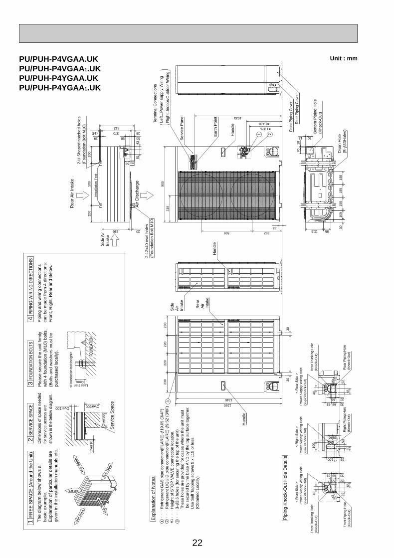
W1 376
W1 428
3
Rea
r Pip
ing
Cov
er
Fron
t Pip
ing
Cov
er
2-U
Sha
ped
notc
hed
hole
s(F
ound
atio
n B
olt M
10)
Inst
alla
tion
Fee
t
Rea
r Air
Inta
ke
Sid
e A
irIn
take
2-12
x40
oval
hol
es(F
ound
atio
n B
olt M
10)
Term
inal
Con
nect
ions
Left.
..Pow
er s
uppl
y W
iring
Rig
ht..I
ndoo
r/O
utdo
or W
iring
[92
92
65
63 68
55 22
33
40R
ear
Trun
king
Hol
e(K
nock
-Out
)
< R
ear
Sid
e >
Rea
r P
ipin
g H
ole
(Kno
ck-O
ut)
Pow
er S
uppl
y W
iring
Hol
e(2
-[27
Kno
ck-O
ut)
40 55
[92
33
100 50
50
100 27 33
92
65
55 22
63 68
40
< R
ight
Sid
e >
Rig
ht P
ipin
g H
ole
(Kno
ck-O
ut)
< F
ront
Sid
e >
Pow
er S
uppl
y W
iring
Hol
e(2
-[27
Kno
ck-O
ut)
Pow
er S
uppl
y W
iring
Hol
e(2
-[27
Kno
ck-O
ut)
Fro
nt T
runk
ing
Hol
e(K
nock
-Out
)
Fro
nt P
ipin
g H
ole
(Kno
ck-O
ut)
Pip
ing
Kno
ck-O
ut H
ole
Det
ails
Dra
in H
ole
(5-[
33H
oles
)
Bot
tom
Pip
ing
Hol
e(K
nock
-Out
)
85215 3010
915
515
515
5
70
7018
181 2Ear
th P
oint
598
Han
dle
Ser
vice
Pan
el
318
900
1033
352
33
4351
50
200
500
200
53
370(14)
412
29
330
Air
Dis
char
ge
20
58
28
Han
dle
Rea
rA
irIn
take
Sid
eA
irIn
take
Han
dle
230
220
220
230
1246
1260
3030
PU/PUH-P4VGAA.UKPU/PUH-P4VGAA1.UKPU/PUH-P4YGAA.UKPU/PUH-P4YGAA1.UK
4PI
PIN
G-W
IRIN
G D
IREC
TIO
NS
3FO
UNDA
TIO
N BO
LTS
FOUN
DATI
ON
Pip
ing
and
wiri
ng c
onne
ctio
nsca
n be
mad
e fr
om 4
dire
ctio
ns:
Fro
nt, R
ight
, Rea
r an
d B
elow
.
SERV
ICE
SPAC
E
Ple
ase
secu
re th
e un
it fir
mly
with
4 fo
unda
tion
(M10
) bo
lts.
(Bol
ts a
nd w
ashe
rs m
ust b
epu
rcha
sed
loca
lly).
30mm
<F
ound
atio
n bo
lt he
ight
>
Less than
Over500Over100
Ser
vice
Spa
ce
Ove
r500
1F
RE
E S
PAC
E (
Aro
und
the
Uni
t)
Dim
ensi
ons
of s
pace
nee
ded
for s
ervi
ce a
cces
s ar
esh
own
in th
e be
low
dia
gram
.
2T
he d
iagr
am b
elow
sho
ws
aba
sic
exam
ple.
Exp
lana
tion
of p
artic
ular
det
ails
are
give
n in
the
inst
alla
tion
man
uals
etc
.
Ove
r10
Ove
r 10m
m
F R E E
Ove
r 500
mm
Ove
r 100
mm
Ove
r 10m
m
Exp
lana
tion
of N
otes
. .
. Ref
riger
ant G
AS
pip
e co
nnec
tion(
FLA
RE
) [
19.0
5 (3
/4F
).
. . R
efrig
eran
t LIQ
UID
pip
e co
nnec
tion(
FLA
RE
) [
9.52
(3/
8F)
. .
. Hei
ght o
f ST
OP
VA
LVE
con
nect
ion
loca
tion.
. .
. 3-[
3.6
hole
s (f
or s
ecur
ing
the
top
of th
e un
it)
T
hese
hol
es a
re p
rovi
ded
for
case
s w
here
the
unit
mus
t
be s
ecur
ed b
y th
e ba
se A
ND
by
the
top
surf
ace
toge
ther
.
U
se S
elf T
appi
ng s
crew
s 5
x L1
5 or
less
.
(
Obt
aine
d Lo
cally
)
32 w11
Unit : mm
OC261-D--1.qxp 05.2.18 11:07 AM Page 22
23
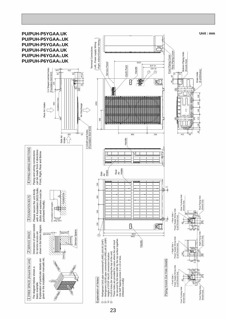
398
w1 478
w1 422
1033
Ear
th P
oint
Term
inal
Con
nect
ions
Left.
..Pow
er s
uppl
y W
iring
Rig
ht..I
ndoo
r/O
utdo
or W
iring
Han
dle
Sid
eA
irIn
take
Rea
rA
irIn
take
Han
dle
Sid
e A
irIn
take
2-12
x40
oval
hol
es(F
ound
atio
n B
olt M
10)
2-U
Sha
ped
notc
hed
hole
s(F
ound
atio
n B
olt M
10)
Rea
r Air
Inta
ke
Air
Dis
char
ge
Han
dle
Ser
vice
Pan
el
Dra
in H
ole
(5-[
33H
oles
)
Bot
tom
Pip
ing
Hol
e(K
nock
-Out
)
Rea
r P
ipin
g C
over
Fro
nt P
ipin
g C
over
[92 92
65
63 68
55 22
33
40R
ear
Trun
king
Hol
e(K
nock
-Out
)
< R
ear
Sid
e >
Rea
r P
ipin
g H
ole
(Kno
ck-O
ut)
Pow
er S
uppl
y W
iring
Hol
e(2
-[27
Kno
ck-O
ut)
40 55
[92
33
100
50
50
100 27 33
92
65
55 22
63 68
40
< R
ight
Sid
e >
Rig
ht P
ipin
g H
ole
(Kno
ck-O
ut)
< F
ront
Sid
e >
Pow
er S
uppl
y W
iring
Hol
e(2
-[27
Kno
ck-O
ut)
Pow
er S
uppl
y W
iring
Hol
e(2
-[27
Kno
ck-O
ut)
Fro
nt T
runk
ing
Hol
e(K
nock
-Out
)
Fro
nt P
ipin
g H
ole
(Kno
ck-O
ut)
Pip
ing
Kno
ck-O
ut H
ole
Det
ails
7018
1890
148
148
148
172
3010
9
215 85598
1 2
1050
352
50
225
600
53
370(14)
29
330 20
Inst
alla
tion
Fee
t
4453
58
323
029
529
523
0
55
12461260
FOUN
DATI
ON
30mm
<F
ound
atio
n bo
lt he
ight
>
Less than
Over500Over100
Ser
vice
Spa
ce
Ove
r500
Ove
r10
The
dia
gram
bel
ow s
how
s a
basi
c ex
ampl
e.E
xpla
natio
n of
par
ticul
ar d
etai
ls a
regi
ven
in th
e in
stal
latio
n m
anua
ls e
tc.
SERV
ICE
SPAC
E1
FR
EE
SPA
CE
(A
roun
d th
e U
nit)
23
FOUN
DATI
ON
BOLT
S
Ple
ase
secu
re th
e un
it fir
mly
with
4 fo
unda
tion
(M10
) bo
lts.
(Bol
ts a
nd w
ashe
rs m
ust b
epu
rcha
sed
loca
lly).
Dim
ensi
ons
of s
pace
nee
ded
for s
ervi
ce a
cces
s ar
esh
own
in th
e be
low
dia
gram
.
4PI
PIN
G-W
IRIN
G D
IREC
TIO
NS
Pip
ing
and
wiri
ng c
onne
ctio
nsca
n be
mad
e fr
om 4
dire
ctio
ns:
Fro
nt, R
ight
, Rea
r an
d B
elow
.
Ove
r 10m
m
F R E E
Ove
r 500
mm
Ove
r 100
mm
Ove
r 10m
m
Exp
lana
tion
of N
otes
. . .
Ref
riger
ant G
AS
pip
e co
nnec
tion(
FLA
RE
) [
19.0
5 (3
/4F
). .
. R
efrig
eran
t LIQ
UID
pip
e co
nnec
tion(
FLA
RE
) [
9.52
(3/
8F)
. . .
Hei
ght o
f ST
OP
VA
LVE
con
nect
ion
loca
tion.
. . .
3-[
3.6
hole
s (f
or s
ecur
ing
the
top
of th
e un
it)
T
hese
hol
es a
re p
rovi
ded
for
case
s w
here
the
unit
mus
t
b
e se
cure
d by
the
base
AN
D b
y th
e to
p su
rfac
e to
geth
er.
Use
Sel
f Tap
ping
scr
ews
5 x
L15
or le
ss.
(Obt
aine
d Lo
cally
)
321 w1
Unit : mmPU/PUH-P5YGAA.UKPU/PUH-P5YGAA1.UKPU/PUH-P5YGAA2.UKPU/PUH-P6YGAA.UKPU/PUH-P6YGAA1.UKPU/PUH-P6YGAA2.UK
OC261-D--1.qxp 05.2.18 11:07 AM Page 23
24
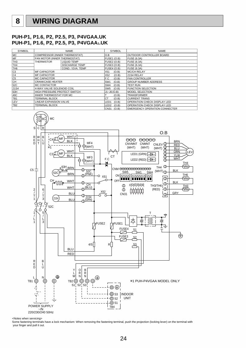
8 WIRING DIAGRAM
<Notes when servicing>Some fastening terminals have a lock mechanism: When removing the fastening terminal, push the projection (locking lever) on the terminal with your finger and pull it out.
SYMBOL NAME SYMBOL NAME
MC COMPRESSOR (INNER THERMOSTAT)MF FAN MOTOR (INNER THERMOSTAT)TH3 THERMISTOR LIQUID TEMPTH4 DISCHARGE TEMPTH6 COND. / EVA. TEMPC3 MF CAPACITORC4 MF CAPACITORC5 MC CAPACITORCH CRANKCASE HEATER52C MC CONTACTOR21S4 4-WAY VALVE SOLENOID COIL63H HIGH PRESSURE PROTECT SWITCH49C INNER THERMOSTAT FOR MCTB1 TERMINAL BLOCKLEV LINEAR EXPANSION VALVETB2 TERMINAL BLOCK
O.B OUTDOOR CONTROLLER BOARDFUSE1 (O.B) FUSE (6.3A)FUSE2 (O.B) FUSE (6.3A)FUSE3 (O.B) FUSE (6.3A)FUSE4 (O.B) FUSE (6.3A)X51 (O.B) MC/CH RELAYX52 (O.B) 21S4 RELAYF.C (O.B) FAN CONTROLLERSW1 (O.B) GROUP NUMBER ADDRESSSW4 (O.B) TEST RUNSW5 (O.B) FUNCTION SELECTIONJ1~J6 (O.B) MODEL SELECTIONT (O.B) TRANSFORMERCT (O.B) CURRENT TRANSLED1 (O.B) OPERATION CHECK DISPLAY LEDLED2 (O.B) OPERATION CHECK DISPLAY LEDCN31 (O.B) EMERGENCY OPERATION CONNECTER
O.B
INDOORUNIT
S C R
MC
RED
WHT
BLU
RED
YLW
ORN
BRN
BLU
C3WHTBLK
WHT
WHT
BRN
BRN
RED
BLU
49C
J1 J2 J3 J4 J5 J6
MF LEVCTMF3
(WHT)
C4
w1
w1 PUH-P4VGAA MODEL ONLY
WHTBLK
MFMF4
(WHT)
52C(PNK)
CH(BLU)
52C
S1
S1
SW1 SW4SW5CNM
LED1 (GRN)
LED2 (RED)
S1TB4POWER SUPPLY
~/N220/230/240 50Hz
S2
S2
S2
S3
S3
FUSE3
FUSE4
S3
ab
63H
CH
52C
TB1 TB2L N
T
OFF
ON
CNLEV(WHT)
CNVMNT(WHT)
CNMNT(WHT)
TH4(WHT)
TH3/TH6(RED)
REDBLU
BLK
GRY
BLK
ORNYLWWHT
BRN
TH4
TH6
TH3
CN31
F.C
X51
C5
2/T1
6/T3
1/L1
5/L3
4/S R
FUSE2 FUSE1
BLU
BLU21S4(GRN)21S4
X52
PUH-P1, P1.6, P2, P2.5, P3, P4VGAA.UKPUH-P1, P1.6, P2, P2.5, P3, P4VGAA 1.UK
OC261-D--1.qxp 05.2.18 11:07 AM Page 24
25
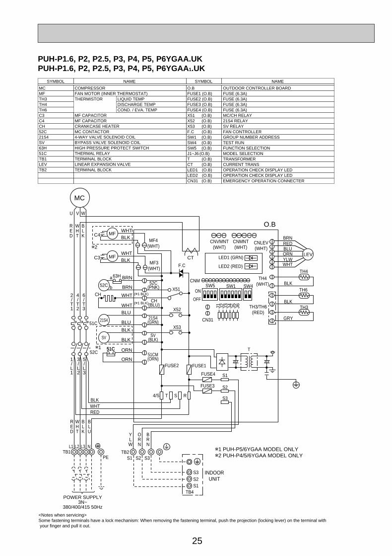
PUH-P1.6, P2, P2.5, P3, P4, P5, P6YGAA.UKPUH-P1.6, P2, P2.5, P3, P4, P5, P6YGAA 1.UK
<Notes when servicing>Some fastening terminals have a lock mechanism: When removing the fastening terminal, push the projection (locking lever) on the terminal with your finger and pull it out.
SYMBOL NAME SYMBOL NAME
MC COMPRESSORMF FAN MOTOR (INNER THERMOSTAT)TH3 THERMISTOR LIQUID TEMPTH4 DISCHARGE TEMPTH6 COND. / EVA. TEMPC3 MF CAPACITORC4 MF CAPACITORCH CRANKCASE HEATER52C MC CONTACTOR21S4 4-WAY VALVE SOLENOID COILSV BYPASS VALVE SOLENOID COIL63H HIGH PRESSURE PROTECT SWITCH51C THERMAL RELAYTB1 TERMINAL BLOCKLEV LINEAR EXPANSION VALVETB2 TERMINAL BLOCK
O.B OUTDOOR CONTROLLER BOARDFUSE1 (O.B) FUSE (6.3A)FUSE2 (O.B) FUSE (6.3A)FUSE3 (O.B) FUSE (6.3A)FUSE4 (O.B) FUSE (6.3A)X51 (O.B) MC/CH RELAYX52 (O.B) 21S4 RELAYX53 (O.B) SV RELAYF.C (O.B) FAN CONTROLLERSW1 (O.B) GROUP NUMBER ADDRESSSW4 (O.B) TEST RUNSW5 (O.B) FUNCTION SELECTIONJ1~J6 (O.B) MODEL SELECTIONT (O.B) TRANSFORMERCT (O.B) CURRENT TRANSLED1 (O.B) OPERATION CHECK DISPLAY LEDLED2 (O.B) OPERATION CHECK DISPLAY LEDCN31 (O.B) EMERGENCY OPERATION CONNECTER
MC
U V W
RED
WHT
BLK
RED
RED
WHT
WHT
BLK
BLK
BLU
POWER SUPPLY3N~
380/400/415 50Hz
51C
52C51C
TB1L1 L2 L3 N
2/T1
6/T3
4/T2
1/L1
5/L3
3/L2
PE
O.B
INDOORUNIT
YLW
ORN
BRN
C3WHTBLK
WHT
WHT
BRN
BRN
J1 J2 J3 J4 J5 J6
MF LEVCT
MF3(WHT)
C4
w2
(w1 BLK)
(w1 BLK)
WHTBLK
MFMF4
(WHT)
52C(PNK)
CH(BLU)
52C
S1
S1
SW1 SW4SW5CNM
LED1 (GRN)
LED2 (RED)
S1TB4
S2
S2
S2
S3
S3
FUSE3
FUSE4
S3
a
b
63H
CH
TB2
T
OFF
ON
CNLEV(WHT)
CNVMNT(WHT)
CNMNT(WHT)
TH4(WHT)
TH3/TH6(RED)
REDBLU
BLK
GRY
BLK
ORNYLWWHT
BRN
TH4
TH6
TH3
CN31
F.C
X51
4/S RST
FUSE2 FUSE1
w1 PUH-P5/6YGAA MODEL ONLYw2 PUH-P4/5/6YGAA MODEL ONLY
51C
BLU
BLU
w1
21S4(GRN)21S4
BLK
BLK
ORN
ORN
SV(BLK)
51CM(ORN)
SV
X52
X53
OC261-D--1.qxp 05.2.18 11:07 AM Page 25
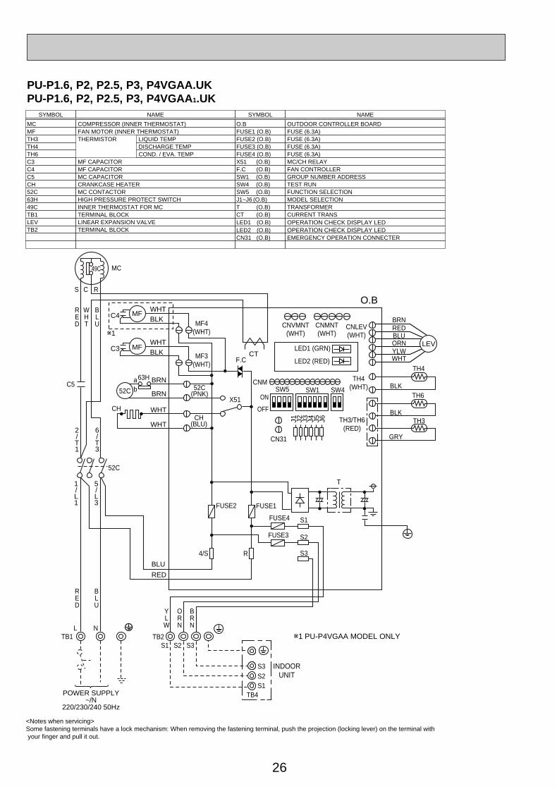
26
PU-P1.6, P2, P2.5, P3, P4VGAA.UKPU-P1.6, P2, P2.5, P3, P4VGAA 1.UK
<Notes when servicing>Some fastening terminals have a lock mechanism: When removing the fastening terminal, push the projection (locking lever) on the terminal with your finger and pull it out.
SYMBOL NAME SYMBOL NAME
MC COMPRESSOR (INNER THERMOSTAT)MF FAN MOTOR (INNER THERMOSTAT)TH3 THERMISTOR LIQUID TEMPTH4 DISCHARGE TEMPTH6 COND. / EVA. TEMPC3 MF CAPACITORC4 MF CAPACITORC5 MC CAPACITORCH CRANKCASE HEATER52C MC CONTACTOR63H HIGH PRESSURE PROTECT SWITCH49C INNER THERMOSTAT FOR MCTB1 TERMINAL BLOCKLEV LINEAR EXPANSION VALVETB2 TERMINAL BLOCK
O.B OUTDOOR CONTROLLER BOARDFUSE1 (O.B) FUSE (6.3A)FUSE2 (O.B) FUSE (6.3A)FUSE3 (O.B) FUSE (6.3A)FUSE4 (O.B) FUSE (6.3A)X51 (O.B) MC/CH RELAYF.C (O.B) FAN CONTROLLERSW1 (O.B) GROUP NUMBER ADDRESSSW4 (O.B) TEST RUNSW5 (O.B) FUNCTION SELECTIONJ1~J6 (O.B) MODEL SELECTIONT (O.B) TRANSFORMERCT (O.B) CURRENT TRANSLED1 (O.B) OPERATION CHECK DISPLAY LEDLED2 (O.B) OPERATION CHECK DISPLAY LEDCN31 (O.B) EMERGENCY OPERATION CONNECTER
O.B
INDOORUNIT
S C R
MC
RED
WHT
BLU
RED
YLW
ORN
BRN
BLU
C3WHTBLK
WHT
WHT
BRN
BRN
RED
BLU
49C
J1 J2 J3 J4 J5 J6
MF LEVCTMF3
(WHT)
C4
w1
w1 PU-P4VGAA MODEL ONLY
WHTBLK
MFMF4
(WHT)
52C(PNK)
CH(BLU)
52C
S1
S1
SW1 SW4SW5CNM
LED1 (GRN)
LED2 (RED)
S1TB4POWER SUPPLY
~/N220/230/240 50Hz
S2
S2
S2
S3
S3
FUSE3
FUSE4
S3
ab
63H
CH
52C
TB1 TB2L N
T
OFF
ON
CNLEV(WHT)
CNVMNT(WHT)
CNMNT(WHT)
TH4(WHT)
TH3/TH6(RED)
REDBLU
BLK
GRY
BLK
ORNYLWWHT
BRN
TH4
TH6
TH3
CN31
F.C
X51
C5
2/T1
6/T3
1/L1
5/L3
4/S R
FUSE2 FUSE1
OC261-D--1.qxp 05.2.18 11:07 AM Page 26
27
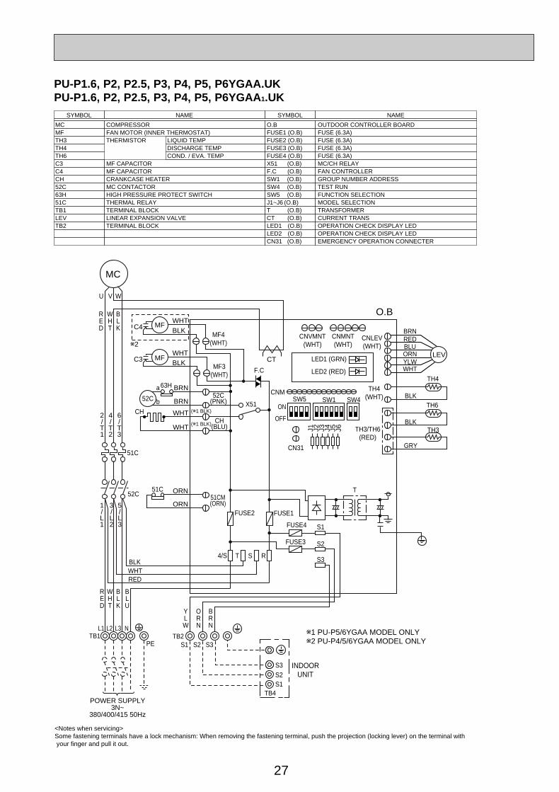
PU-P1.6, P2, P2.5, P3, P4, P5, P6YGAA.UKPU-P1.6, P2, P2.5, P3, P4, P5, P6YGAA 1.UK
<Notes when servicing>Some fastening terminals have a lock mechanism: When removing the fastening terminal, push the projection (locking lever) on the terminal with your finger and pull it out.
SYMBOL NAME SYMBOL NAME
MC COMPRESSORMF FAN MOTOR (INNER THERMOSTAT)TH3 THERMISTOR LIQUID TEMPTH4 DISCHARGE TEMPTH6 COND. / EVA. TEMPC3 MF CAPACITORC4 MF CAPACITORCH CRANKCASE HEATER52C MC CONTACTOR63H HIGH PRESSURE PROTECT SWITCH51C THERMAL RELAYTB1 TERMINAL BLOCKLEV LINEAR EXPANSION VALVETB2 TERMINAL BLOCK
O.B OUTDOOR CONTROLLER BOARDFUSE1 (O.B) FUSE (6.3A)FUSE2 (O.B) FUSE (6.3A)FUSE3 (O.B) FUSE (6.3A)FUSE4 (O.B) FUSE (6.3A)X51 (O.B) MC/CH RELAYF.C (O.B) FAN CONTROLLERSW1 (O.B) GROUP NUMBER ADDRESSSW4 (O.B) TEST RUNSW5 (O.B) FUNCTION SELECTIONJ1~J6 (O.B) MODEL SELECTIONT (O.B) TRANSFORMERCT (O.B) CURRENT TRANSLED1 (O.B) OPERATION CHECK DISPLAY LEDLED2 (O.B) OPERATION CHECK DISPLAY LEDCN31 (O.B) EMERGENCY OPERATION CONNECTER
MC
U V W
RED
WHT
BLK
RED
RED
WHT
WHT
BLK
BLK
BLU
POWER SUPPLY3N~
380/400/415 50Hz
51C
52C51C
TB1L1 L2 L3 N
2/T1
6/T3
4/T2
1/L1
5/L3
3/L2
PE
O.B
INDOORUNIT
YLW
ORN
BRN
C3WHTBLK
WHT
WHT
BRN
BRN
J1 J2 J3 J4 J5 J6
MF LEVCT
MF3(WHT)
C4
w2
(w1 BLK)
(w1 BLK)
WHTBLK
MFMF4
(WHT)
52C(PNK)
CH(BLU)
52C
S1
S1
SW1 SW4SW5CNM
LED1 (GRN)
LED2 (RED)
S1TB4
S2
S2
S2
S3
S3
FUSE3
FUSE4
S3
ORN
ORN51CM(ORN)
a
b
63H
CH
TB2
T
OFF
ON
CNLEV(WHT)
CNVMNT(WHT)
CNMNT(WHT)
TH4(WHT)
TH3/TH6(RED)
REDBLU
BLK
GRY
BLK
ORNYLWWHT
BRN
TH4
TH6
TH3
CN31
F.C
X51
4/S RST
FUSE2 FUSE1
w1 PU-P5/6YGAA MODEL ONLYw2 PU-P4/5/6YGAA MODEL ONLY
OC261-D--1.qxp 05.2.18 11:07 AM Page 27
28
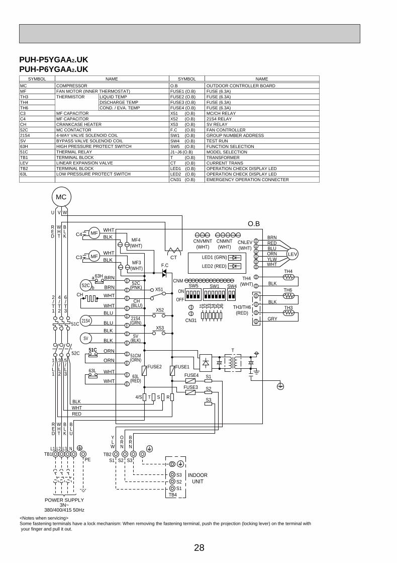
PUH-P5YGAA2.UKPUH-P6YGAA2.UK
<Notes when servicing>Some fastening terminals have a lock mechanism: When removing the fastening terminal, push the projection (locking lever) on the terminal with your finger and pull it out.
SYMBOL NAME SYMBOL NAME
MC COMPRESSORMF FAN MOTOR (INNER THERMOSTAT)TH3 THERMISTOR LIQUID TEMPTH4 DISCHARGE TEMPTH6 COND. / EVA. TEMPC3 MF CAPACITORC4 MF CAPACITORCH CRANKCASE HEATER52C MC CONTACTOR21S4 4-WAY VALVE SOLENOID COILSV BYPASS VALVE SOLENOID COIL63H HIGH PRESSURE PROTECT SWITCH51C THERMAL RELAYTB1 TERMINAL BLOCKLEV LINEAR EXPANSION VALVETB2 TERMINAL BLOCK63L LOW PRESSURE PROTECT SWITCH
O.B OUTDOOR CONTROLLER BOARDFUSE1 (O.B) FUSE (6.3A)FUSE2 (O.B) FUSE (6.3A)FUSE3 (O.B) FUSE (6.3A)FUSE4 (O.B) FUSE (6.3A)X51 (O.B) MC/CH RELAYX52 (O.B) 21S4 RELAYX53 (O.B) SV RELAYF.C (O.B) FAN CONTROLLERSW1 (O.B) GROUP NUMBER ADDRESSSW4 (O.B) TEST RUNSW5 (O.B) FUNCTION SELECTIONJ1~J6 (O.B) MODEL SELECTIONT (O.B) TRANSFORMERCT (O.B) CURRENT TRANSLED1 (O.B) OPERATION CHECK DISPLAY LEDLED2 (O.B) OPERATION CHECK DISPLAY LEDCN31 (O.B) EMERGENCY OPERATION CONNECTER
MC
U V W
RED
WHT
BLK
RED
RED
WHT
WHT
BLK
BLK
BLU
POWER SUPPLY3N~
380/400/415 50Hz
51C
52C51C
TB1L1 L2 L3 N
2/T1
6/T3
4/T2
1/L1
5/L3
3/L2
PE
O.B
INDOORUNIT
YLW
ORN
BRN
C3WHTBLK
WHT
WHT
BRN
BRN
J1 J2 J3 J4 J5 J6
MF LEVCT
MF3(WHT)
C4WHTBLK
MFMF4
(WHT)
52C(PNK)
CH(BLU)
52C
S1
S1
SW1 SW4SW5CNM
LED1 (GRN)
LED2 (RED)
S1TB4
S2
S2
S2
S3
S3
FUSE3
FUSE4
S3
a
b
63H
CH
TB2
T
OFF
ON
CNLEV(WHT)
CNVMNT(WHT)
CNMNT(WHT)
TH4(WHT)
TH3/TH6(RED)
REDBLU
BLK
GRY
BLK
ORNYLWWHT
BRN
TH4
TH6
TH3
CN31
F.C
X51
4/S RST
FUSE2 FUSE1
51C
BLU
BLU21S4(GRN)21S4
BLK
BLK
ORN
ORN
SV(BLK)
51CM(ORN)
63L WHT
WHT63L
(RED)
SV
X52
X53
OC261-D--1.qxp 05.2.18 11:07 AM Page 28
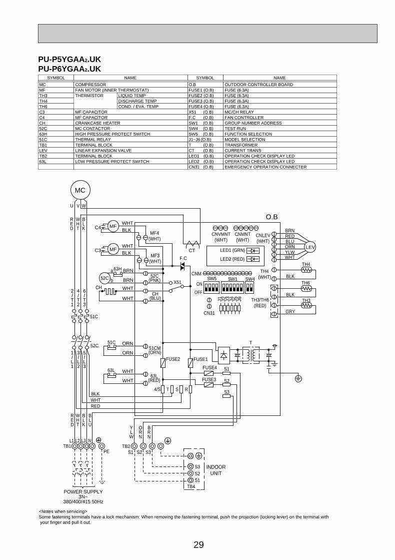
29
PU-P5YGAA2.UKPU-P6YGAA2.UK
<Notes when servicing>Some fastening terminals have a lock mechanism: When removing the fastening terminal, push the projection (locking lever) on the terminal with your finger and pull it out.
SYMBOL NAME SYMBOL NAME
MC COMPRESSORMF FAN MOTOR (INNER THERMOSTAT)TH3 THERMISTOR LIQUID TEMPTH4 DISCHARGE TEMPTH6 COND. / EVA. TEMPC3 MF CAPACITORC4 MF CAPACITORCH CRANKCASE HEATER52C MC CONTACTOR63H HIGH PRESSURE PROTECT SWITCH51C THERMAL RELAYTB1 TERMINAL BLOCKLEV LINEAR EXPANSION VALVETB2 TERMINAL BLOCK63L LOW PRESSURE PROTECT SWITCH
O.B OUTDOOR CONTROLLER BOARDFUSE1 (O.B) FUSE (6.3A)FUSE2 (O.B) FUSE (6.3A)FUSE3 (O.B) FUSE (6.3A)FUSE4 (O.B) FUSE (6.3A)X51 (O.B) MC/CH RELAYF.C (O.B) FAN CONTROLLERSW1 (O.B) GROUP NUMBER ADDRESSSW4 (O.B) TEST RUNSW5 (O.B) FUNCTION SELECTIONJ1~J6 (O.B) MODEL SELECTIONT (O.B) TRANSFORMERCT (O.B) CURRENT TRANSLED1 (O.B) OPERATION CHECK DISPLAY LEDLED2 (O.B) OPERATION CHECK DISPLAY LEDCN31 (O.B) EMERGENCY OPERATION CONNECTER
MC
U V W
RED
WHT
BLK
RED
RED
WHT
WHT
BLK
BLK
BLU
POWER SUPPLY3N~
380/400/415 50Hz
51C
52C51C
TB1L1 L2 L3 N
2/T1
6/T3
4/T2
1/L1
5/L3
3/L2
PE
O.B
INDOORUNIT
YLW
ORN
BRN
C3WHTBLK
WHT
WHT
BRN
BRN
J1 J2 J3 J4 J5 J6
MF LEVCT
MF3(WHT)
C4WHTBLK
MFMF4
(WHT)
52C(PNK)
CH(BLU)
52C
S1
S1
SW1 SW4SW5CNM
LED1 (GRN)
LED2 (RED)
S1TB4
S2
S2
S2
S3
S3
FUSE3
FUSE4
S3
ORN
ORN51CM(ORN)
63L WHT
WHT63L
(RED)
a
b
63H
CH
TB2
T
OFF
ON
CNLEV(WHT)
CNVMNT(WHT)
CNMNT(WHT)
TH4(WHT)
TH3/TH6(RED)
REDBLU
BLK
GRY
BLK
ORNYLWWHT
BRN
TH4
TH6
TH3
CN31
F.C
X51
4/S RST
FUSE2 FUSE1
OC261-D--1.qxp 05.2.18 11:07 AM Page 29
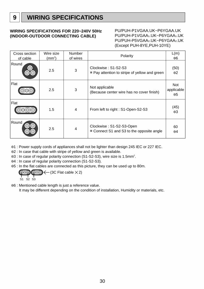
30
9 WIRING SPECIFICATIONS
Cross section of cable
Round
2.5
2.5
1.5
2.5
3
3
4
4
(50)✽2
(45)✽3
60✽4
Notapplicable
✽5
Flat
✽1 : Power supply cords of appliances shall not be lighter than design 245 IEC or 227 IEC.✽2 : In case that cable with stripe of yellow and green is available.✽3 : In case of regular polarity connection (S1-S2-S3), wire size is 1.5mm2. ✽4 : In case of regular polarity connection (S1-S2-S3). ✽5 : In the flat cables are connected as this picture, they can be used up to 80m.
✽6 : Mentioned cable length is just a reference value. It may be different depending on the condition of installation, Humidity or materials, etc.
Flat
Round
Wire size(mm2)
Numberof wires
Clockwise : S1-S2-S3w Pay attention to stripe of yellow and green
Clockwise : S1-S2-S3-Openw Connect S1 and S3 to the opposite angle
Not applicable(Because center wire has no cover finish)
From left to right : S1-Open-S2-S3
PolarityL(m) ✽6
(3C Flat cable ✕ 2)
S1 S2 S3
WIRING SPECIFICATIONS FOR 220~240V 50Hz(INDOOR-OUTDOOR CONNECTING CABLE)
PU/PUH-P1VGAA.UK~P6YGAA.UKPU/PUH-P1VGAA1.UK~P6YGAA1.UKPU/PUH-P5VGAA2.UK~P6YGAA2.UK(Except PUH-8YE,PUH-10YE)
OC261-D--1.qxp 05.2.18 11:07 AM Page 30
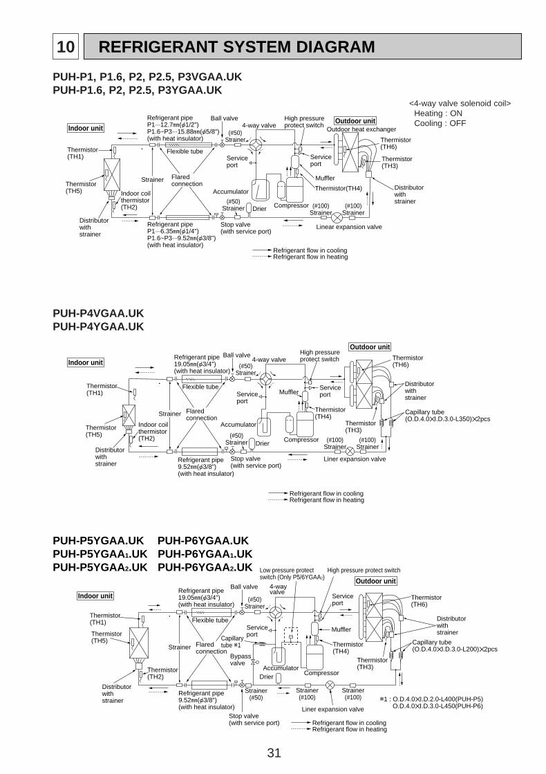
31
10 REFRIGERANT SYSTEM DIAGRAM
PUH-P5YGAA.UK PUH-P6YGAA.UKPUH-P5YGAA1.UK PUH-P6YGAA 1.UKPUH-P5YGAA2.UK PUH-P6YGAA 2.UK
Indoor unit
Outdoor unit
Thermistor(TH2)
Strainer
Flexible tubeServiceport
AccumulatorCompressor
Refrigerant pipe19.05A({3/4")(with heat insulator)
Refrigerant pipe9.52A({3/8")(with heat insulator)
Stop valve(with service port)
4-way valve
Serviceport
High pressure protect switch
Thermistor(TH3)
Capillary tube(O.D.4.0✕I.D.3.0-L200)✕2pcs
Distributorwithstrainer
Flaredconnection
Drier
Liner expansion valve
Bypassvalve
Thermistor(TH5)
Thermistor(TH1)
Muffler
Thermistor(TH4)
Thermistor(TH6)
Distributorwithstrainer
Capillarytube w1
Refrigerant flow in coolingRefrigerant flow in heating
w1 : O.D.4.0✕I.D.2.0-L400(PUH-P5)O.D.4.0✕I.D.3.0-L450(PUH-P6)
Ball valve
(#50)Strainer
Strainer(#100)
Strainer(#100)
Strainer(#50)
Low pressure protect switch (Only P5/6YGAA2)
PUH-P4VGAA.UKPUH-P4YGAA.UK
Indoor unit
Outdoor unit
Thermistor(TH5)
Strainer
Flexible tubeServiceport
Accumulator
Compressor
Refrigerant pipe19.05A({3/4")(with heat insulator)
Refrigerant pipe9.52A({3/8")(with heat insulator)
Stop valve(with service port)
4-way valve
Serviceport
High pressureprotect switch
Thermistor(TH3)
Capillary tube(O.D.4.0✕I.D.3.0-L350)✕2pcs
Distributorwithstrainer
Flaredconnection
Refrigerant flow in coolingRefrigerant flow in heating
Liner expansion valve
Drier
Thermistor(TH1)
Indoor coilthermistor(TH2)
Thermistor(TH4)
Muffler
Thermistor(TH6)
Distributorwithstrainer
Ball valve
(#50)Strainer
(#100)Strainer
(#100)Strainer
(#50)Strainer
PUH-P1, P1.6, P2, P2.5, P3VGAA.UKPUH-P1.6, P2, P2.5, P3YGAA.UK
Indoor unitOutdoor unit
Thermistor(TH1)
Strainer Flaredconnection
Flexible tubeServiceport
Accumulator
Ball valve
(#50)Strainer
Compressor
Refrigerant pipeP1···12.7A({1/2")P1.6~P3···15.88A({5/8")(with heat insulator)
Refrigerant pipeP1···6.35A({1/4")P1.6~P3···9.52A({3/8")(with heat insulator)
Stop valve(with service port)
4-way valve
Serviceport
High pressureprotect switch
Outdoor heat exchanger
Thermistor(TH3)
Distributorwithstrainer
Thermistor(TH6)
Distributorwithstrainer
(#100)Strainer
(#100)Strainer
Drier
Indoor coilthermistor(TH2)
Thermistor(TH5)
Muffler
Thermistor(TH4)
Linear expansion valve
(#50)Strainer
Refrigerant flow in coolingRefrigerant flow in heating
<4-way valve solenoid coil>Heating : ONCooling : OFF
OC261-D--2.qxp 05.2.18 11:13 AM Page 31
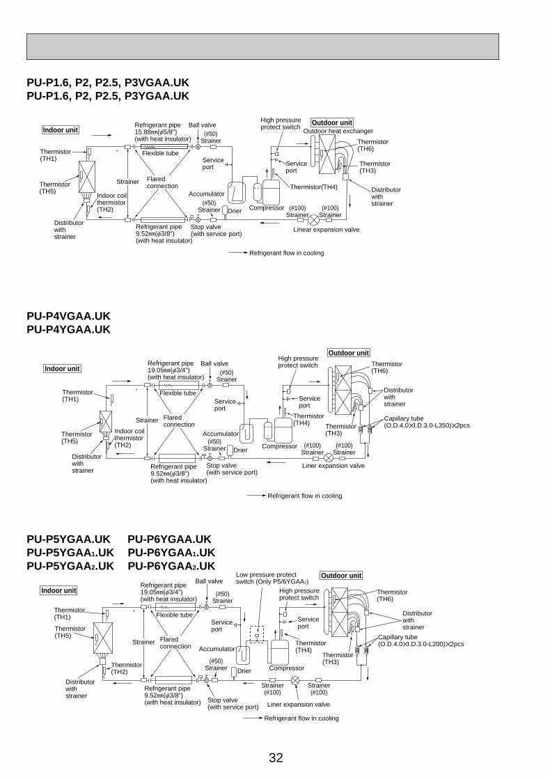
32
PU-P5YGAA.UK PU-P6YGAA.UKPU-P5YGAA1.UK PU-P6YGAA 1.UKPU-P5YGAA2.UK PU-P6YGAA 2.UK
Indoor unit
Outdoor unit
Thermistor(TH2)
Strainer
Flexible tubeServiceport
Accumulator
Compressor
Refrigerant pipe19.05A({3/4")(with heat insulator)
Refrigerant pipe9.52A({3/8")(with heat insulator)
Serviceport
High pressureprotect switch
Thermistor(TH3)
Capillary tube(O.D.4.0✕I.D.3.0-L200)✕2pcs
Distributorwithstrainer
Flaredconnection
Drier
Thermistor(TH5)
Thermistor(TH1)
Thermistor(TH4)
Thermistor(TH6)
Distributorwithstrainer
Refrigerant flow in cooling
Stop valve(with service port) Liner expansion valve
Ball valve
(#50)Strainer
Strainer(#100)
Strainer(#100)
(#50)Strainer
Low pressure protect switch (Only P5/6YGAA2)
PU-P4VGAA.UKPU-P4YGAA.UK
Indoor unit
Outdoor unit
Thermistor(TH5)
Strainer
Flexible tubeServiceport
Accumulator
Compressor
Refrigerant pipe19.05A({3/4")(with heat insulator)
Refrigerant pipe9.52A({3/8")(with heat insulator)
Stop valve(with service port)
Serviceport
High pressureprotect switch
Thermistor(TH3)
Capillary tube(O.D.4.0✕I.D.3.0-L350)✕2pcs
Distributorwithstrainer
Flaredconnection
Refrigerant flow in cooling
Liner expansion valve
Drier
Thermistor(TH1)
Indoor coilthermistor(TH2)
Thermistor(TH4)
Thermistor(TH6)
Distributorwithstrainer
Ball valve(#50)
Strainer
(#100)Strainer
(#100)Strainer
(#50)Strainer
PU-P1.6, P2, P2.5, P3VGAA.UKPU-P1.6, P2, P2.5, P3YGAA.UK
Indoor unitOutdoor unit
Thermistor(TH1)
Strainer Flaredconnection
Flexible tubeServiceport
Accumulator
Compressor
Refrigerant pipe15.88A({5/8")(with heat insulator)
Refrigerant pipe9.52A({3/8")(with heat insulator)
Stop valve(with service port)
Serviceport
High pressureprotect switch
Outdoor heat exchanger
Thermistor(TH3)
Distributorwithstrainer
Thermistor(TH6)
Distributorwithstrainer
Drier
Indoor coilthermistor(TH2)
Thermistor(TH5)
Thermistor(TH4)
Linear expansion valve
Refrigerant flow in cooling
Ball valve(#50)
Strainer
(#100)Strainer
(#100)Strainer
(#50)Strainer
OC261-D--2.qxp 05.2.18 11:13 AM Page 32
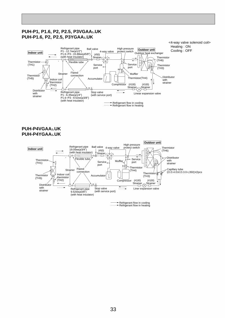
33
PUH-P4VGAA1.UKPUH-P4YGAA1.UK
Indoor unit
Outdoor unit
Thermistor(TH5)
Strainer
Flexible tubeServiceport
Accumulator
Compressor
Refrigerant pipe19.05A({3/4")(with heat insulator)
Refrigerant pipe9.52A({3/8")(with heat insulator)
Stop valve(with service port)
4-way valve
Serviceport
High pressureprotect switch
Thermistor(TH3)
Capillary tube(O.D.4.0✕I.D.3.0-L350)✕2pcs
Distributorwithstrainer
Flaredconnection
Refrigerant flow in coolingRefrigerant flow in heating
Liner expansion valve
Thermistor(TH1)
Indoor coilthermistor(TH2)
Thermistor(TH4)
Muffler
Thermistor(TH6)
Distributorwithstrainer
Ball valve(#50)
Strainer
(#100)Strainer
(#100)Strainer
PUH-P1, P1.6, P2, P2.5, P3VGAA 1.UKPUH-P1.6, P2, P2.5, P3YGAA1.UK
Indoor unitOutdoor unit
Thermistor(TH1)
Strainer Flaredconnection
Flexible tubeServiceport
Accumulator
Ball valve
Compressor
Refrigerant pipeP1···12.7A({1/2")P1.6~P3···15.88A({5/8")(with heat insulator)
Refrigerant pipeP1···6.35A({1/4")P1.6~P3···9.52A({3/8")(with heat insulator)
Stop valve(with service port)
4-way valve
Serviceport
High pressureprotect switch
Outdoor heat exchanger
Thermistor(TH3)
Distributorwithstrainer
Thermistor(TH6)
Distributorwithstrainer
Indoor coilthermistor(TH2)
Thermistor(TH5)
Muffler
Thermistor(TH4)
Linear expansion valve
Refrigerant flow in coolingRefrigerant flow in heating
(#50)Strainer
(#100)Strainer
(#100)Strainer
<4-way valve solenoid coil>Heating : ONCooling : OFF
OC261-D--2.qxp 05.2.18 11:13 AM Page 33
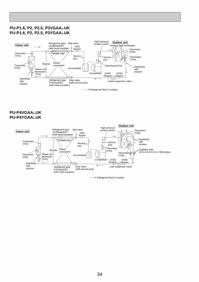
34
PU-P4VGAA1.UKPU-P4YGAA1.UK
Indoor unit
Outdoor unit
Thermistor(TH5)
Strainer
Flexible tubeServiceport
Accumulator
Compressor
Refrigerant pipe19.05A({3/4")(with heat insulator)
Refrigerant pipe9.52A({3/8")(with heat insulator)
Stop valve(with service port)
Serviceport
High pressureprotect switch
Thermistor(TH3)
Capillary tube(O.D.4.0✕I.D.3.0-R350)✕2pcs
Distributorwithstrainer
Flaredconnection
Refrigerant flow in cooling
Liner expansion valve
Thermistor(TH1)
Indoor coilthermistor(TH2)
Thermistor(TH4)
Thermistor(TH6)
Distributorwithstrainer
Ball valve(#50)
Strainer
(#100)Strainer
(#100)Strainer
PU-P1.6, P2, P2.5, P3VGAA1.UKPU-P1.6, P2, P2.5, P3YGAA1.UK
Indoor unitOutdoor unit
Thermistor(TH1)
Strainer Flaredconnection
Flexible tubeServiceport
Accumulator
Compressor
Refrigerant pipe15.88A({5/8")(with heat insulator)
Refrigerant pipe9.52A({3/8")(with heat insulator)
Stop valve(with service port)
Serviceport
High pressureprotect switch
Outdoor heat exchanger
Thermistor(TH3)
Distributorwithstrainer
Thermistor(TH6)
Distributorwithstrainer
Indoor coilthermistor(TH2)
Thermistor(TH5)
Thermistor(TH4)
Linear expansion valve
Refrigerant flow in cooling
Ball valve(#50)
Strainer
(#100)Strainer
(#100)Strainer
OC261-D--2.qxp 05.2.18 11:13 AM Page 34
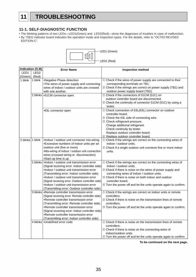
35
11 TROUBLESHOOTING
1 blink
2 blinks
LED1 (Green)
LED2 (Red)
1 blink
2 blinks
1 blink
2 blinks
3 blinks
4 blinks
•Negative Phase detection•The wires of power supply and connecting wires of indoor / outdoor units are crossed with one another.•51CM connector open
•Start-up time is up
•Indoor / outdoor unit connector mis-wiring•Excessive numbers of indoor units per an outdoor unit (five or more)•Mis-wiring of indoor / outdoor unit connection wires (crossed wiring or disconnection)
•Indoor / outdoor unit transmission error(Transmitting error: Outdoor controller side)
•Indoor / outdoor unit transmission error(Signal receiving error: Indoor controller side)•Indoor / outdoor unit transmission error(Transmitting error: Indoor controller side)•Indoor / outdoor unit transmission error(Signal receiving error :Outdoor controller side)
•Remote controller transmission error(Transmitting error: Indoor controller side)•Undefined error code
•Remote controller transmission error(Signal receiving error: Remote controller side)•Remote controller transmission error(Transmitting error: Remote controller side)•Remote controller transmission error(Signal receiving error: Indoor controller side)
1 Check if the wires of power supply are connected to their corresponding terminals on TB1. 2 Check if the wirings are correct on power supply (TB1) and outdoor power supply board (TB2).
1 Check if the wirings are correct on the connecting wires of indoor / outdoor units.2 Check if a single outdoor unit connects five or more indoor units.
1 Check if the connectors of 51CM (51C) on outdoor controller board are disconnected. 2 Check the continuity of connector 51CM (51C) by using a tester.
•63L connector open 1 Check connection of 63L(63L) connector on outdoor controller board.
2 Check the 63L side of connecting wire. 3 Check refrigerant pressure.
Charge additional refrigerant.Check continuity by tester.Replace outdoor controller board.
4 Replace outdoor controller board.
1 Check if the wirings are correct on indoor units or remote controllers.2 Check if there is noise on the transmission lines of remote controllers.3 Turn the power off and let the units operate again to confirm.
1 Check if there is noise on the transmission lines of remote controllers.2 Check if there is noise on the connecting wires of indoor/outdoor units.3 Turn the power off and let the units operate again to confirm.
To be continued on the next page.
1 Check if the wirings are correct on the connecting wires of indoor / outdoor units.2 Check if there is noise on the wires of power supply and connecting wires of indoor / outdoor units.3 Check if there is noise on both indoor and outdoor controller board.4 Turn the power off and let the units operate again to confirm.
Indication (O.B) Error Name Inspection method
LED1 (Green)
LED2 (Red)
11-1. SELF-DIAGNOSTIC FUNCTION• The blinking patterns of two LEDs—LED1(Green) and LED2(Red)—show the diagnoses of troubles in case of malfunction.• By 7SEG indicator board indicates the operation mode and inspection types. For the details, refer to “OCT03 REVISED
EDITION-C”.
OC261-D--2.qxp 05.2.18 11:13 AM Page 35
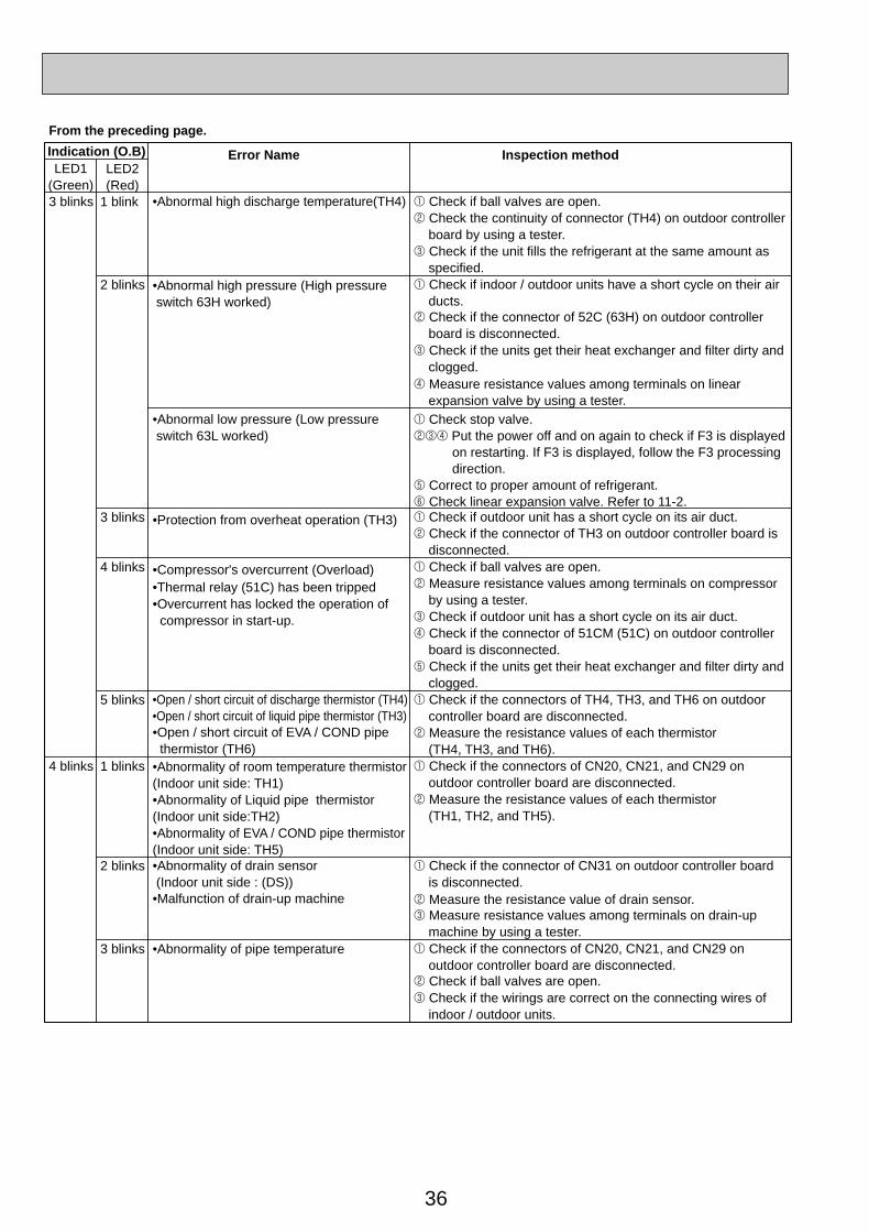
36
3 blinks
4 blinks
LED1 (Green)
LED2 (Red)
1 blink
2 blinks
3 blinks
4 blinks
5 blinks
1 blinks
2 blinks
3 blinks
•Abnormal high discharge temperature(TH4)
From the preceding page.
•Abnormal high pressure (High pressure switch 63H worked)
•Protection from overheat operation (TH3)
•Compressor's overcurrent (Overload)•Thermal relay (51C) has been tripped•Overcurrent has locked the operation of compressor in start-up.
•Open / short circuit of discharge thermistor (TH4)•Open / short circuit of liquid pipe thermistor (TH3)•Open / short circuit of EVA / COND pipe thermistor (TH6)•Abnormality of room temperature thermistor(Indoor unit side: TH1)•Abnormality of Liquid pipe thermistor (Indoor unit side:TH2)•Abnormality of EVA / COND pipe thermistor (Indoor unit side: TH5)•Abnormality of drain sensor (Indoor unit side : (DS))•Malfunction of drain-up machine
•Abnormality of pipe temperature
1 Check if ball valves are open. 2 Check the continuity of connector (TH4) on outdoor controller board by using a tester.
1 Check if outdoor unit has a short cycle on its air duct.2 Check if the connector of TH3 on outdoor controller board is disconnected.
1 Check if the connectors of TH4, TH3, and TH6 on outdoor controller board are disconnected.2 Measure the resistance values of each thermistor (TH4, TH3, and TH6).1 Check if the connectors of CN20, CN21, and CN29 on outdoor controller board are disconnected.2 Measure the resistance values of each thermistor (TH1, TH2, and TH5).
3 Check if the unit fills the refrigerant at the same amount as specified. 1 Check if indoor / outdoor units have a short cycle on their air ducts.
•Abnormal low pressure (Low pressure switch 63L worked)
1 Check stop valve.234 Put the power off and on again to check if F3 is displayed
on restarting. If F3 is displayed, follow the F3 processing direction.
5 Correct to proper amount of refrigerant.6 Check linear expansion valve. Refer to 11-2.
2 Check if the connector of 52C (63H) on outdoor controller board is disconnected.3 Check if the units get their heat exchanger and filter dirty and clogged.4 Measure resistance values among terminals on linear expansion valve by using a tester.
1 Check if ball valves are open.2 Measure resistance values among terminals on compressor by using a tester. 3 Check if outdoor unit has a short cycle on its air duct.
1 Check if the connector of CN31 on outdoor controller board is disconnected.2 Measure the resistance value of drain sensor.3 Measure resistance values among terminals on drain-up machine by using a tester. 1 Check if the connectors of CN20, CN21, and CN29 on outdoor controller board are disconnected.2 Check if ball valves are open.3 Check if the wirings are correct on the connecting wires of indoor / outdoor units.
4 Check if the connector of 51CM (51C) on outdoor controller board is disconnected.5 Check if the units get their heat exchanger and filter dirty and clogged.
Indication (O.B) Error Name Inspection method
OC261-D--2.qxp 05.2.18 11:13 AM Page 36
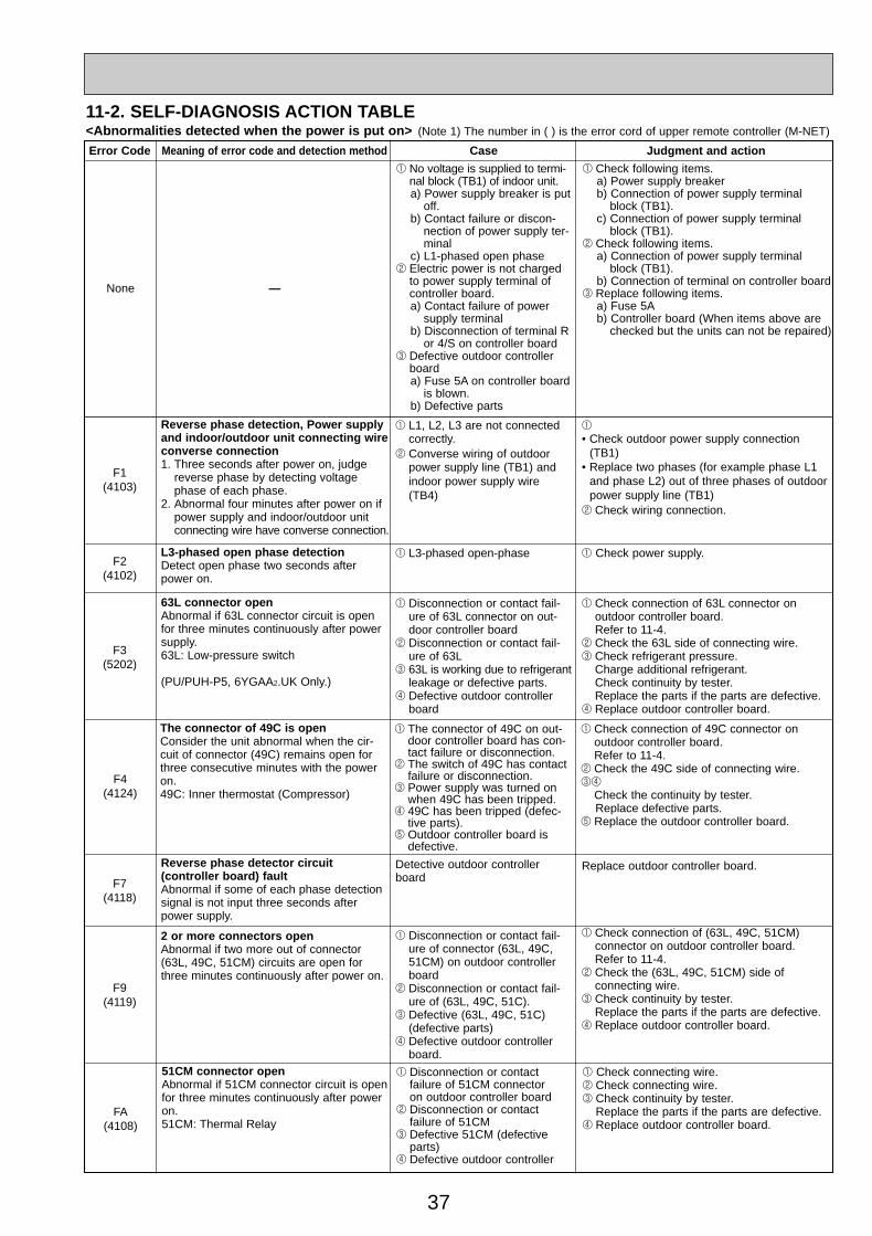
37
11-2. SELF-DIAGNOSIS ACTION TABLE
Error Code Meaning of error code and detection method Case Judgment and action
F3(5202)
63L connector openAbnormal if 63L connector circuit is openfor three minutes continuously after powersupply.63L: Low-pressure switch
(PU/PUH-P5, 6YGAA2.UK Only.)
1 Disconnection or contact fail-ure of 63L connector on out-door controller board
2 Disconnection or contact fail-ure of 63L
3 63L is working due to refrigerantleakage or defective parts.
4 Defective outdoor controllerboard
1 Check connection of 63L connector on outdoor controller board. Refer to 11-4.
2 Check the 63L side of connecting wire. 3 Check refrigerant pressure.
Charge additional refrigerant.Check continuity by tester.Replace the parts if the parts are defective.
4 Replace outdoor controller board.
F7(4118)
Reverse phase detector circuit (controller board) faultAbnormal if some of each phase detectionsignal is not input three seconds afterpower supply.
Detective outdoor controllerboard
Replace outdoor controller board.
F9(4119)
2 or more connectors openAbnormal if two more out of connector(63L, 49C, 51CM) circuits are open forthree minutes continuously after power on.
1 Disconnection or contact fail-ure of connector (63L, 49C,51CM) on outdoor controllerboard
2 Disconnection or contact fail-ure of (63L, 49C, 51C).
3 Defective (63L, 49C, 51C)(defective parts)
4 Defective outdoor controllerboard.
1 Check connection of (63L, 49C, 51CM) connector on outdoor controller board.Refer to 11-4.
2 Check the (63L, 49C, 51CM) side of connecting wire.
3 Check continuity by tester.Replace the parts if the parts are defective.
4 Replace outdoor controller board.
F4(4124)
The connector of 49C is openConsider the unit abnormal when the cir-cuit of connector (49C) remains open forthree consecutive minutes with the poweron. 49C: Inner thermostat (Compressor)
1 The connector of 49C on out-door controller board has con-tact failure or disconnection.
2 The switch of 49C has contactfailure or disconnection.
3 Power supply was turned onwhen 49C has been tripped.
4 49C has been tripped (defec-tive parts).
5 Outdoor controller board isdefective.
1 Check connection of 49C connector on outdoor controller board. Refer to 11-4.
2 Check the 49C side of connecting wire. 34
Check the continuity by tester. Replace defective parts.
5 Replace the outdoor controller board.
FA(4108)
51CM connector openAbnormal if 51CM connector circuit is openfor three minutes continuously after poweron.51CM: Thermal Relay
1 Disconnection or contact failure of 51CM connector on outdoor controller board
2 Disconnection or contact failure of 51CM
3 Defective 51CM (defectiveparts)
4 Defective outdoor controller
1 Check connecting wire.2 Check connecting wire.3 Check continuity by tester.
Replace the parts if the parts are defective.4 Replace outdoor controller board.
None —
1 No voltage is supplied to termi-nal block (TB1) of indoor unit.a) Power supply breaker is put
off.b) Contact failure or discon-
nection of power supply ter-minal
c) L1-phased open phase2 Electric power is not charged
to power supply terminal ofcontroller board.a) Contact failure of power
supply terminalb) Disconnection of terminal R
or 4/S on controller board3 Defective outdoor controller
boarda) Fuse 5A on controller board
is blown.b) Defective parts
1 Check following items.a) Power supply breakerb) Connection of power supply terminal
block (TB1).c) Connection of power supply terminal
block (TB1).2 Check following items.
a) Connection of power supply terminalblock (TB1).
b) Connection of terminal on controller board3 Replace following items.
a) Fuse 5Ab) Controller board (When items above are
checked but the units can not be repaired)
F1(4103)
Reverse phase detection, Power supplyand indoor/outdoor unit connecting wireconverse connection1. Three seconds after power on, judge
reverse phase by detecting voltagephase of each phase.
2. Abnormal four minutes after power on ifpower supply and indoor/outdoor unitconnecting wire have converse connection.
1 L1, L2, L3 are not connectedcorrectly.
2 Converse wiring of outdoorpower supply line (TB1) andindoor power supply wire(TB4)
1
• Check outdoor power supply connection(TB1)
• Replace two phases (for example phase L1and phase L2) out of three phases of outdoorpower supply line (TB1)
2 Check wiring connection.
F2(4102)
L3-phased open phase detectionDetect open phase two seconds afterpower on.
1 L3-phased open-phase 1 Check power supply.
<Abnormalities detected when the power is put on> (Note 1) The number in ( ) is the error cord of upper remote controller (M-NET)
OC261-D--2.qxp 05.2.18 11:13 AM Page 37
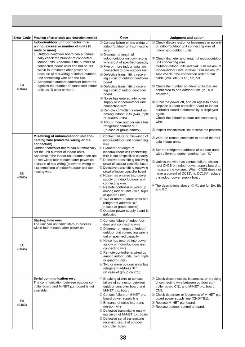
38
Error Code Meaning of error code and detection method Judgment and action
Eb(6845)
Mis-wiring of indoor/outdoor unit con-necting wire (converse wiring or dis-connection)Outdoor controller board can automaticallyset the unit number of indoor units.Abnormal if the indoor unit number can notbe set within four minutes after power onbecause of mis-wiring (converse wiring ordisconnection) of indoor/outdoor unit con-necting wire.
EC(6846)
Start-up time overThe unit can not finish start-up processwithin four minutes after power on.
Ed(0403)
Serial communication errorThe communication between outdoor con-troller board and M-NET p.c. board is notavailable.
1 Breaking of wire or contactfailure of connector betweenoutdoor controller board andM-NET p.c. board.
2 Contact failure of M-NET p.c.board power supply line
3 Entrance of noise into trans-mission wire
4 Defective transmitting receiv-ing circuit of M-NET p.c. board
5 Defective serial transmittingreceiving circuit of outdoorcontroller board
1 Check disconnection, looseness, or breakingof connecting wire between outdoor con-troller board CN1 and M-NET p.c. boardCN5.
2 Check departure or looseness of M-NET p.c.board power supply line (CND-TB1).
3 Replace M-NET p.c. board.4 Replace outdoor controller board.
Case
1 Contact failure of indoor/out-door unit connecting wire
2 Diameter or length of indoor/outdoor unit connecting wire isout of specified capacity.
6 Noise has entered into powersupply or indoor/outdoor unitconnecting wire.
7 Remote controller is wired upamong indoor units (twin, tripleor quadro units).
8 Two or more outdoor units hasrefrigerant address “0.” (In case of group control).
1 Contact failure or mis-wiring ofindoor/outdoor unit connectingwire
2 Diameter or length ofindoor/outdoor unit connectingwire is out of specified capacity.
4 Defective transmitting receivingcircuit of outdoor controller board
5 Defective transmitting receivingcircuit of indoor controller board
6 Noise has entered into powersupply or indoor/outdoor unitconnecting wire.
7 Remote controller is wired upamong indoor units (twin, tripleor quadro units).
8 Two or more outdoor units hasrefrigerant address “0.”
(In case of group control).9 Outdoor power supply board is
defective.
Indoor/outdoor unit connector mis-wiring, excessive number of units (5units or more)1. Outdoor controller board can automati-
cally check the number of connectedindoor units. Abnormal if the number ofconnected indoor units can not be setwithin four minutes after power onbecause of mis-wiring of indoor/outdoorunit connecting wire and the like.
2. Abnormal if outdoor controller board rec-ognizes the number of connected indoorunits as “5 units or more”.
1 Check disconnection or looseness or polarityof indoor/outdoor unit connecting wire ofindoor and outdoor units.
2 Check diameter and length of indoor/outdoorunit connecting wire.Outdoor-indoor units’ interval: 50m maximumIndoor-indoor units’ interval: 30m maximumAlso check if the connection order of flatcable (VVF etc.) is S1, S2, S3.
3 Check the number of indoor units that areconnected to one outdoor unit. (If EA isdetected.)
45 Put the power off, and on again to check.Replace outdoor controller board or indoorcontroller board if abnormality is displayedagain.Check the indoor/ outdoor unit connectingwire.
6 Inspect transmission line to solve the problem.
7 Wire the remote controller to one of the mul-tiple indoor units.
8 Set the refrigerant address of outdoor unitswith different number starting from “0.”
9 Unless the wire has contact failure, discon-nect CN2S on indoor power supply board tomeasure the voltage. When CN2S does nothave a current of DC12V to DC16V, replacethe indoor power supply board.
w The descriptions above, 1-9, are for EA, Eband EC.
1 Contact failure or mis-wiring ofindoor/outdoor unit connectingwire.
2 Diameter or length ofindoor/outdoor unit connectingwire is out of specified capacity.
3 Five or more indoor units areconnected to one outdoor unit.
4 Defective transmitting receiv-ing circuit of outdoor controllerboard
5 Defective transmitting receiv-ing circuit of indoor controllerboard
6 Noise has entered into powersupply or indoor/outdoor unitconnecting wire.
7 Remote controller is wired upamong indoor units (twin, tripleor quadro units).
8 Two or more outdoor units hasrefrigerant address “0.” (In case of group control).
EA(6844)
OC261-D--2.qxp 05.2.18 11:13 AM Page 38
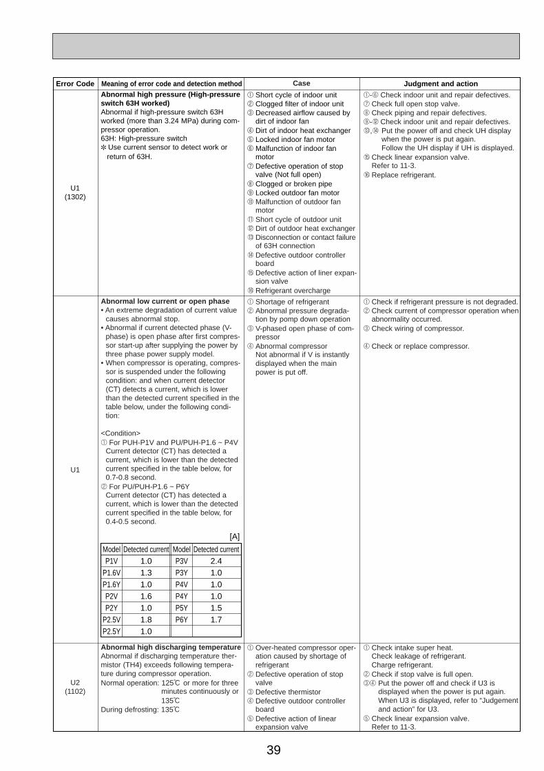
39
Error Code Meaning of error code and detection method Judgment and action
U1(1302)
Abnormal high pressure (High-pressureswitch 63H worked)Abnormal if high-pressure switch 63Hworked (more than 3.24 MPa) during com-pressor operation.63H: High-pressure switch✽ Use current sensor to detect work or
return of 63H.
1 Short cycle of indoor unit2 Clogged filter of indoor unit3 Decreased airflow caused by
dirt of indoor fan4 Dirt of indoor heat exchanger5 Locked indoor fan motor6 Malfunction of indoor fan
motor7 Defective operation of stop
valve (Not full open)8 Clogged or broken pipe9 Locked outdoor fan motor0 Malfunction of outdoor fan
motor1 Short cycle of outdoor unit2 Dirt of outdoor heat exchanger3 Disconnection or contact failure
of 63H connection4 Defective outdoor controller
board5 Defective action of liner expan-
sion valve6 Refrigerant overcharge
1-6 Check indoor unit and repair defectives.7 Check full open stop valve.8 Check piping and repair defectives.9-2 Check indoor unit and repair defectives.3,4 Put the power off and check UH display
when the power is put again.Follow the UH display if UH is displayed.
5 Check linear expansion valve.Refer to 11-3.
6 Replace refrigerant.
U1
Abnormal low current or open phase• An extreme degradation of current value
causes abnormal stop.• Abnormal if current detected phase (V-
phase) is open phase after first compres-sor start-up after supplying the power bythree phase power supply model.
• When compressor is operating, compres-sor is suspended under the followingcondition: and when current detector(CT) detects a current, which is lowerthan the detected current specified in thetable below, under the following condi-tion:
<Condition>1 For PUH-P1V and PU/PUH-P1.6 ~ P4V
Current detector (CT) has detected a current, which is lower than the detectedcurrent specified in the table below, for0.7-0.8 second.
2 For PU/PUH-P1.6 ~ P6YCurrent detector (CT) has detected a current, which is lower than the detectedcurrent specified in the table below, for0.4-0.5 second.
1 Shortage of refrigerant 2 Abnormal pressure degrada-
tion by pomp down operation3 V-phased open phase of com-
pressor4 Abnormal compressor
Not abnormal if V is instantlydisplayed when the mainpower is put off.
1 Check if refrigerant pressure is not degraded.2 Check current of compressor operation when
abnormality occurred.3 Check wiring of compressor.
4 Check or replace compressor.
Case
ModelP1V
P1.6VP1.6YP2VP2Y
P2.5VP2.5Y
Detected current1.01.31.01.61.01.81.0
ModelP3VP3YP4VP4YP5YP6Y
Detected current2.41.01.01.01.51.7
[A]
U2(1102)
Abnormal high discharging temperatureAbnormal if discharging temperature ther-mistor (TH4) exceeds following tempera-ture during compressor operation.Normal operation: 125: or more for three
minutes continuously or135:
During defrosting: 135:
1 Over-heated compressor oper-ation caused by shortage ofrefrigerant
2 Defective operation of stopvalve
3 Defective thermistor4 Defective outdoor controller
board5 Defective action of linear
expansion valve
1 Check intake super heat.Check leakage of refrigerant.Charge refrigerant.
2 Check if stop valve is full open.34 Put the power off and check if U3 is
displayed when the power is put again.When U3 is displayed, refer to “Judgementand action” for U3.
5 Check linear expansion valve.Refer to 11-3.
OC261-D--2.qxp 05.2.18 11:13 AM Page 39
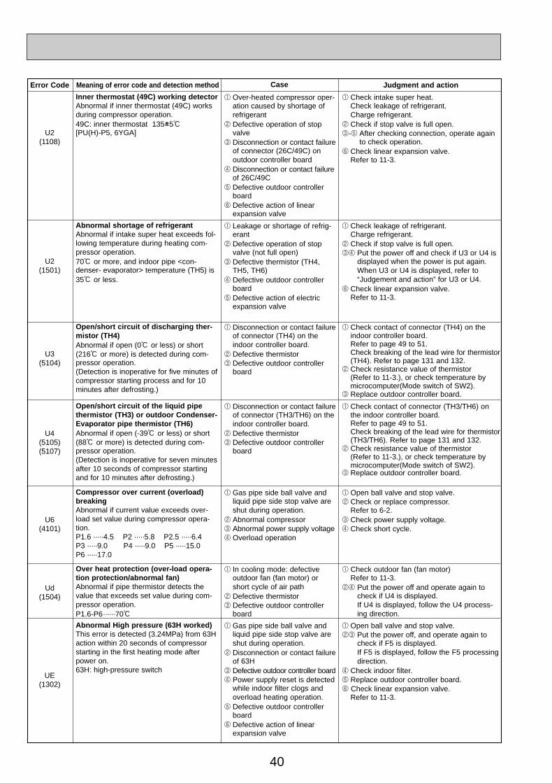
40
Error Code Meaning of error code and detection method Judgment and action
U3(5104)
Open/short circuit of discharging ther-mistor (TH4)Abnormal if open (0: or less) or short(216: or more) is detected during com-pressor operation.(Detection is inoperative for five minutes ofcompressor starting process and for 10minutes after defrosting.)
1 Disconnection or contact failureof connector (TH4) on theindoor controller board.
2 Defective thermistor3 Defective outdoor controller
board
1 Check contact of connector (TH4) on theindoor controller board.Refer to page 49 to 51.Check breaking of the lead wire for thermistor(TH4). Refer to page 131 and 132.
2 Check resistance value of thermistor(Refer to 11-3.), or check temperature bymicrocomputer(Mode switch of SW2).
3 Replace outdoor controller board.
U4(5105)(5107)
Open/short circuit of the liquid pipethermistor (TH3) or outdoor Condenser-Evaporator pipe thermistor (TH6)Abnormal if open (-39: or less) or short(88: or more) is detected during com-pressor operation.(Detection is inoperative for seven minutesafter 10 seconds of compressor startingand for 10 minutes after defrosting.)
1 Disconnection or contact failureof connector (TH3/TH6) on theindoor controller board.
2 Defective thermistor3 Defective outdoor controller
board
1 Check contact of connector (TH3/TH6) onthe indoor controller board.Refer to page 49 to 51.Check breaking of the lead wire for thermistor(TH3/TH6). Refer to page 131 and 132.
2 Check resistance value of thermistor (Refer to 11-3.), or check temperature bymicrocomputer(Mode switch of SW2).
3 Replace outdoor controller board.
U6(4101)
Compressor over current (overload)breakingAbnormal if current value exceeds over-load set value during compressor opera-tion.P1.6 ·····4.5 P2 ·····5.8 P2.5 ·····6.4P3 ·····9.0 P4 ·····9.0 P5 ·····15.0P6 ·····17.0
1 Gas pipe side ball valve andliquid pipe side stop valve areshut during operation.
2 Abnormal compressor3 Abnormal power supply voltage4 Overload operation
1 Open ball valve and stop valve.2 Check or replace compressor.
Refer to 6-2.3 Check power supply voltage.4 Check short cycle.
Ud(1504)
Over heat protection (over-load opera-tion protection/abnormal fan)Abnormal if pipe thermistor detects thevalue that exceeds set value during com-pressor operation.P1.6-P6······70:
1 In cooling mode: defective outdoor fan (fan motor) orshort cycle of air path
2 Defective thermistor3 Defective outdoor controller
board
1 Check outdoor fan (fan motor)Refer to 11-3.
24 Put the power off and operate again tocheck if U4 is displayed.If U4 is displayed, follow the U4 process-ing direction.
UE(1302)
Abnormal High pressure (63H worked)This error is detected (3.24MPa) from 63Haction within 20 seconds of compressorstarting in the first heating mode afterpower on.63H: high-pressure switch
1 Gas pipe side ball valve andliquid pipe side stop valve areshut during operation.
2 Disconnection or contact failureof 63H
3 Defective outdoor controller board4 Power supply reset is detected
while indoor filter clogs andoverload heating operation.
5 Defective outdoor controllerboard
6 Defective action of linearexpansion valve
1 Open ball valve and stop valve.23 Put the power off, and operate again to
check if F5 is displayed.If F5 is displayed, follow the F5 processingdirection.
4 Check indoor filter.5 Replace outdoor controller board.6 Check linear expansion valve.
Refer to 11-3.
Case
U2(1108)
Inner thermostat (49C) working detectorAbnormal if inner thermostat (49C) worksduring compressor operation.49C: inner thermostat 135I5:[PU(H)-P5, 6YGA]
1 Over-heated compressor oper-ation caused by shortage ofrefrigerant
2 Defective operation of stopvalve
3 Disconnection or contact failureof connector (26C/49C) onoutdoor controller board
4 Disconnection or contact failureof 26C/49C
5 Defective outdoor controllerboard
6 Defective action of linearexpansion valve
1 Check intake super heat.Check leakage of refrigerant.Charge refrigerant.
2 Check if stop valve is full open.3-5 After checking connection, operate again
to check operation.6 Check linear expansion valve.
Refer to 11-3.
U2(1501)
Abnormal shortage of refrigerantAbnormal if intake super heat exceeds fol-lowing temperature during heating com-pressor operation.70: or more, and indoor pipe <con-denser- evaporator> temperature (TH5) is35: or less.
1 Leakage or shortage of refrig-erant
2 Defective operation of stopvalve (not full open)
3 Defective thermistor (TH4,TH5, TH6)
4 Defective outdoor controllerboard
5 Defective action of electricexpansion valve
1 Check leakage of refrigerant.Charge refrigerant.
2 Check if stop valve is full open.34 Put the power off and check if U3 or U4 is
displayed when the power is put again.When U3 or U4 is displayed, refer to“Judgement and action” for U3 or U4.
6 Check linear expansion valve.Refer to 11-3.
OC261-D--2.qxp 05.2.18 11:13 AM Page 40
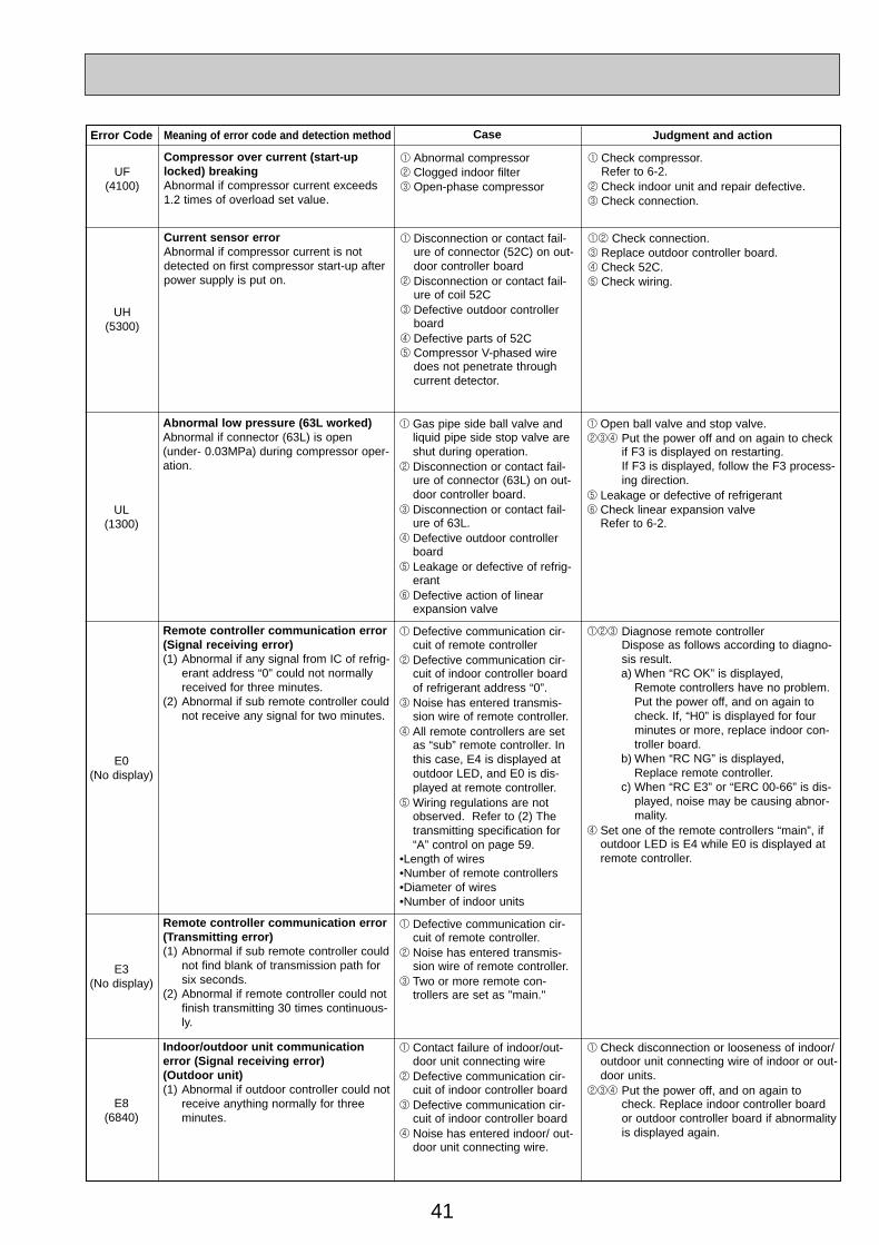
41
Error Code Meaning of error code and detection method Judgment and action
UL(1300)
Abnormal low pressure (63L worked)Abnormal if connector (63L) is open(under- 0.03MPa) during compressor oper-ation.
1 Gas pipe side ball valve andliquid pipe side stop valve areshut during operation.
2 Disconnection or contact fail-ure of connector (63L) on out-door controller board.
3 Disconnection or contact fail-ure of 63L.
4 Defective outdoor controllerboard
5 Leakage or defective of refrig-erant
6 Defective action of linearexpansion valve
1 Open ball valve and stop valve.234 Put the power off and on again to check
if F3 is displayed on restarting.If F3 is displayed, follow the F3 process-ing direction.
5 Leakage or defective of refrigerant6 Check linear expansion valve
Refer to 6-2.
E0(No display)
Remote controller communication error(Signal receiving error)(1) Abnormal if any signal from IC of refrig-
erant address “0” could not normallyreceived for three minutes.
(2) Abnormal if sub remote controller couldnot receive any signal for two minutes.
1 Defective communication cir-cuit of remote controller
2 Defective communication cir-cuit of indoor controller boardof refrigerant address “0”.
3 Noise has entered transmis-sion wire of remote controller.
4 All remote controllers are setas “sub” remote controller. Inthis case, E4 is displayed atoutdoor LED, and E0 is dis-played at remote controller.
5 Wiring regulations are notobserved. Refer to (2) Thetransmitting specification for“A” control on page 59.
•Length of wires •Number of remote controllers•Diameter of wires •Number of indoor units
123 Diagnose remote controllerDispose as follows according to diagno-sis result.a) When “RC OK” is displayed,
Remote controllers have no problem.Put the power off, and on again tocheck. If, “H0” is displayed for fourminutes or more, replace indoor con-troller board.
b) When “RC NG” is displayed,Replace remote controller.
c) When “RC E3” or “ERC 00-66” is dis-played, noise may be causing abnor-mality.
4 Set one of the remote controllers “main”, ifoutdoor LED is E4 while E0 is displayed atremote controller.
E3(No display)
Remote controller communication error(Transmitting error)(1) Abnormal if sub remote controller could
not find blank of transmission path forsix seconds.
(2) Abnormal if remote controller could notfinish transmitting 30 times continuous-ly.
1 Defective communication cir-cuit of remote controller.
2 Noise has entered transmis-sion wire of remote controller.
3 Two or more remote con-trollers are set as "main."
E8(6840)
Indoor/outdoor unit communicationerror (Signal receiving error)(Outdoor unit)(1) Abnormal if outdoor controller could not
receive anything normally for threeminutes.
1 Contact failure of indoor/out-door unit connecting wire
2 Defective communication cir-cuit of indoor controller board
3 Defective communication cir-cuit of indoor controller board
4 Noise has entered indoor/ out-door unit connecting wire.
1 Check disconnection or looseness of indoor/outdoor unit connecting wire of indoor or out-door units.
234 Put the power off, and on again tocheck. Replace indoor controller boardor outdoor controller board if abnormalityis displayed again.
Case
UF(4100)
Compressor over current (start-uplocked) breakingAbnormal if compressor current exceeds1.2 times of overload set value.
1 Abnormal compressor2 Clogged indoor filter3 Open-phase compressor
1 Check compressor.Refer to 6-2.
2 Check indoor unit and repair defective.3 Check connection.
UH(5300)
Current sensor errorAbnormal if compressor current is notdetected on first compressor start-up afterpower supply is put on.
1 Disconnection or contact fail-ure of connector (52C) on out-door controller board
2 Disconnection or contact fail-ure of coil 52C
3 Defective outdoor controllerboard
4 Defective parts of 52C5 Compressor V-phased wire
does not penetrate throughcurrent detector.
12 Check connection.3 Replace outdoor controller board.4 Check 52C.5 Check wiring.
OC261-D--2.qxp 05.2.18 11:13 AM Page 41
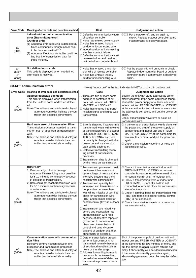
42
Error Code Meaning of error code and detection method Case Judgment and action
A0(6600)
Address duplicate definitionThis error is displayed when transmissionfrom the units of same address is detect-ed.Note) The address and attribute displayed
at remote controller indicate the con-troller that detected abnormality.
1 There are two or more sameaddress of controller of out-door unit, indoor unit, FRESHMASTER, or LOSSNAY.
2 Noise has entered into trans-mission signal and signal wastransformed.
Search the unit with same address as abnor-mality occurred. If the same address is found,shut of the power supply of outdoor unit andindoor unit and FRESH MASTER or LOSSNAYat the same time for two minutes or more afterthe address is corrected, and put the power onagain.Check transmission waveform or noise ontransmission wire.
A2(6602)
Hard ware error of transmission PlineTransmission processor intended to trans-mit “0”, but “1” appeared on transmissionwire.Note) The address and attribute display at
remote controller indicate the con-troller that detected abnormality.
1 Error is detected if waveform istransformed when wiring worksof transmission wire of outdoorunit, indoor unit, FRESH MAS-TER or LOSSNAY are done,or polarity is changed with thepower on and transmissiondata collide each other.
2 Defective transmitting receiv-ing circuit of transmissionprocessor
3 Transmission data is changedby the noise on transmission.
1 If the works of transmission wire is done withthe power on, shut off the power supply ofoutdoor unit and indoor unit and FRESHMASTER or LOSSNAY at the same time fortwo minutes or more, and put the power onagain.
2 Check transmission waveform or noise ontransmission wire.
A3(6603)
BUS BUSY1. Over error by collision damage
Abnormal if transmitting is not possiblefor 8-10 minutes continuously becauseof collision of transmission.
2. Data could not reach transmission wirefor 8-10 minutes continuously becauseof noise or etc.
Note) The address and attribute displayedat remote controller indicate the con-troller that detected abnormality.
1 Transmission processor couldnot transmit because shortcycle voltage of noise and thelike have entered into trans-mission wire continuously.
2 Transmission quantity hasincreased and transmission isnot possible because therewas wiring mistake of terminalblock for transmission wire(TB3) and terminal block forcentral control (TB7) in outdoorunit.
3 Transmission are mixed withothers and occupation rate on transmission wire rosebecause of defective repeater(a function to connector or disconnect transmission ofcontrol and central control system) of outdoor unit, thenabnormality is detected.
1 Check if transmission wire of indoor unit,FRESH MASTER, LOSSNAY, or remote controller is not connected to terminal blockfor central control (TB7) of outdoor unit.
2 Check if transmission wore of indoor unit,FRESH MASTER or LOSSNAY is not connected to terminal block for transmissionwire of outdoor unit.
3 Check if terminal block for transmission wire(TB3) and terminal block for central control(TB7) is not connected.
4 Check transmission waveform or noise ontransmission wire.
A6(6606)
Communication error with communica-tion PlineDefective communication between unitprocessor and transmission processorNote) The address and attribute display at
remote controller indicate the con-troller that detected abnormality.
1 Data of transmission proces-sor or unit processor is nottransmitted normally becauseof accidental trouble such asnoise or thunder surge.
2 Address forwarding from unitprocessor is not transmittednormally because of defectivetransmission processor hard-ware.
Shut of the power supply of outdoor unit andindoor unit and FRESH MASTER or LOSSNAYat the same time for two minutes or more, andput the power on again. System returns nor-mally if abnormality was accidental malfunction.If the same abnormality generates again,abnormality-generated controller may be defec-tive.
<M-NET communication error> (Note) “Indoor unit” in the text indicates M-NET p.c. board in outdoor unit.
Error Code Meaning of error code and detection method Judgment and action
E9(6841)
Indoor/outdoor unit communicationerror (Transmitting error)(Outdoor unit)(1) Abnormal if “0” receiving is detected 30
times continuously though indoor con-troller has transmitted “1”.
(2) Abnormal if outdoor controller could notfind blank of transmission path forthree minutes.
1 Defective communication circuitof outdoor controller
2 Noise has entered power supply.3 Noise has entered indoor/
outdoor unit connecting wire.4 Indoor/ outdoor unit connecting
wire has contact failure. 5 Defective communication circuit
between indoor and outdoorunit on indoor controller board.
123 Put the power off, and on again tocheck. Replace outdoor controller boardif abnormality is displayed again.
EF(6607
or6608)
Not defined error codeThis code is displayed when not definederror code is received.
1 Noise has entered transmis-sion wire of remote controller.
2 Noise has entered indoor/ outdoor unit connecting wire.
12 Put the power off, and on again to check.Replace indoor controller board or outdoorcontroller board if abnormality is displayedagain.
Case
OC261-D--2.qxp 05.2.18 11:13 AM Page 42
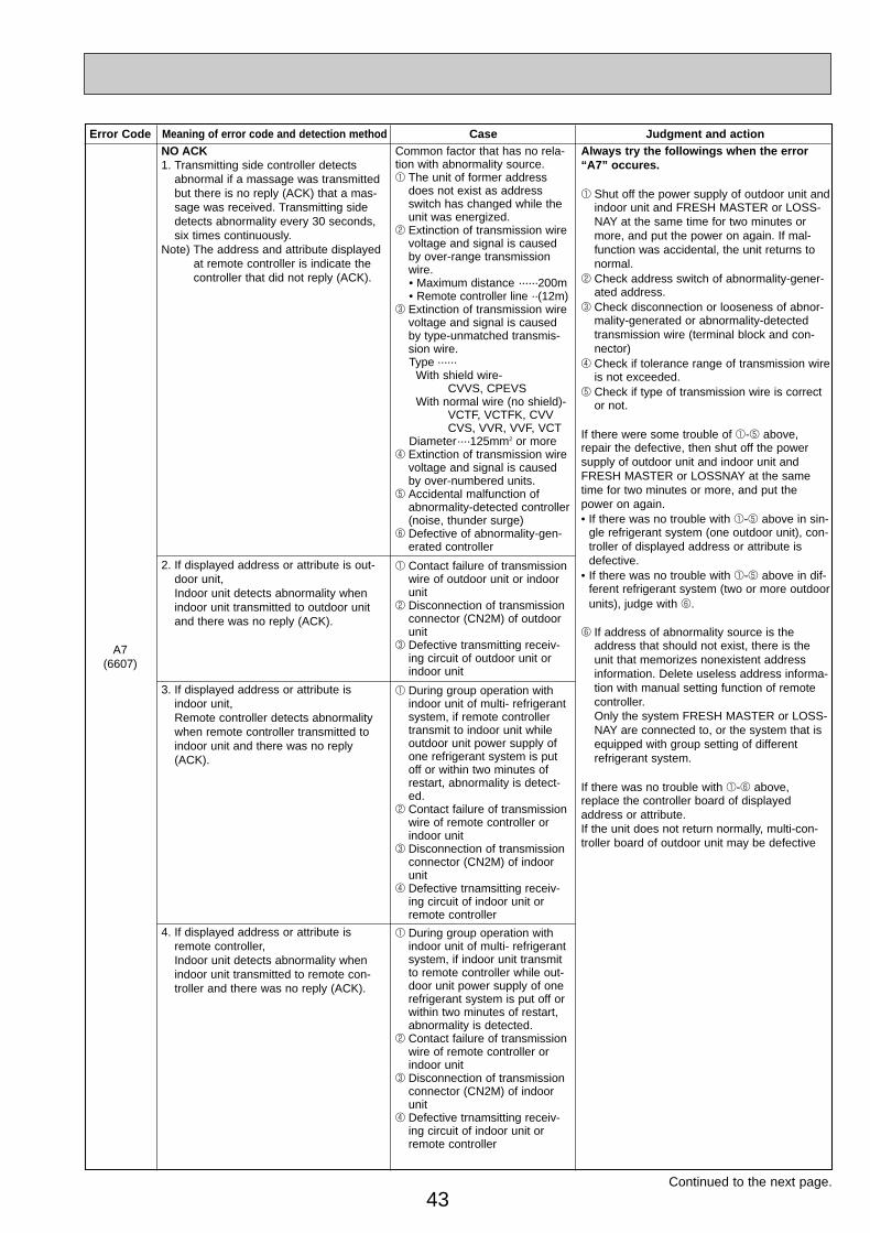
43
Error Code Meaning of error code and detection method Case Judgment and action
A7(6607)
NO ACK1. Transmitting side controller detects
abnormal if a massage was transmittedbut there is no reply (ACK) that a mas-sage was received. Transmitting sidedetects abnormality every 30 seconds,six times continuously.
Note) The address and attribute displayedat remote controller is indicate thecontroller that did not reply (ACK).
Common factor that has no rela-tion with abnormality source.1 The unit of former address
does not exist as addressswitch has changed while theunit was energized.
2 Extinction of transmission wirevoltage and signal is causedby over-range transmissionwire.• Maximum distance ······200m• Remote controller line ··(12m)
3 Extinction of transmission wirevoltage and signal is causedby type-unmatched transmis-sion wire.Type ······
With shield wire- CVVS, CPEVS
With normal wire (no shield)-VCTF, VCTFK, CVV CVS, VVR, VVF, VCT
Diameter····125mm2 or more 4 Extinction of transmission wire
voltage and signal is causedby over-numbered units.
5 Accidental malfunction ofabnormality-detected controller(noise, thunder surge)
6 Defective of abnormality-gen-erated controller
2. If displayed address or attribute is out-door unit,Indoor unit detects abnormality whenindoor unit transmitted to outdoor unitand there was no reply (ACK).
1 Contact failure of transmissionwire of outdoor unit or indoorunit
2 Disconnection of transmissionconnector (CN2M) of outdoorunit
3 Defective transmitting receiv-ing circuit of outdoor unit orindoor unit
Always try the followings when the error “A7” occures.
1 Shut off the power supply of outdoor unit andindoor unit and FRESH MASTER or LOSS-NAY at the same time for two minutes ormore, and put the power on again. If mal-function was accidental, the unit returns tonormal.
2 Check address switch of abnormality-gener-ated address.
3 Check disconnection or looseness of abnor-mality-generated or abnormality-detectedtransmission wire (terminal block and con-nector)
4 Check if tolerance range of transmission wireis not exceeded.
5 Check if type of transmission wire is corrector not.
If there were some trouble of 1-5 above,repair the defective, then shut off the powersupply of outdoor unit and indoor unit andFRESH MASTER or LOSSNAY at the sametime for two minutes or more, and put thepower on again.• If there was no trouble with 1-5 above in sin-
gle refrigerant system (one outdoor unit), con-troller of displayed address or attribute isdefective.
• If there was no trouble with 1-5 above in dif-ferent refrigerant system (two or more outdoorunits), judge with 6.
6 If address of abnormality source is theaddress that should not exist, there is theunit that memorizes nonexistent addressinformation. Delete useless address informa-tion with manual setting function of remotecontroller.Only the system FRESH MASTER or LOSS-NAY are connected to, or the system that isequipped with group setting of differentrefrigerant system.
If there was no trouble with 1-6 above,replace the controller board of displayedaddress or attribute.If the unit does not return normally, multi-con-troller board of outdoor unit may be defective
3. If displayed address or attribute isindoor unit,Remote controller detects abnormalitywhen remote controller transmitted toindoor unit and there was no reply(ACK).
1 During group operation withindoor unit of multi- refrigerantsystem, if remote controllertransmit to indoor unit whileoutdoor unit power supply ofone refrigerant system is putoff or within two minutes ofrestart, abnormality is detect-ed.
2 Contact failure of transmissionwire of remote controller orindoor unit
3 Disconnection of transmissionconnector (CN2M) of indoorunit
4 Defective trnamsitting receiv-ing circuit of indoor unit orremote controller
4. If displayed address or attribute isremote controller,Indoor unit detects abnormality whenindoor unit transmitted to remote con-troller and there was no reply (ACK).
1 During group operation withindoor unit of multi- refrigerantsystem, if indoor unit transmitto remote controller while out-door unit power supply of onerefrigerant system is put off orwithin two minutes of restart,abnormality is detected.
2 Contact failure of transmissionwire of remote controller orindoor unit
3 Disconnection of transmissionconnector (CN2M) of indoorunit
4 Defective trnamsitting receiv-ing circuit of indoor unit orremote controller
Continued to the next page.
OC261-D--2.qxp 05.2.18 11:13 AM Page 43
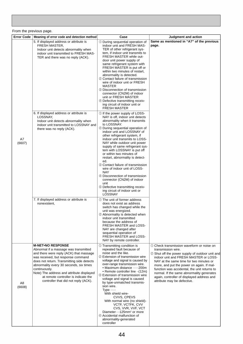
44
Error Code Meaning of error code and detection method Case Judgment and action
A7(6607)
A8(6608)
5. If displayed address or attribute isFRESH MASTER, Indoor unit detects abnormality whenindoor unit transmitted to FRESH MAS-TER and there was no reply (ACK).
1 During sequential operation ofindoor unit and FRESH MAS-TER of other refrigerant sys-tem, if indoor unit transmits toFRESH MASTER while out-door unit power supply ofsame refrigerant system withFRESH MASTER is put off orwithin two minutes of restart,abnormality is detected.
2 Contact failure of transmissionwire of indoor unit or FRESHMASTER
3 Disconnection of transmissionconnector (CN2M) of indoorunit or FRESH MASTER
4 Defective transmitting receiv-ing circuit of indoor unit orFRESH MASTER
6. If displayed address or attribute isLOSSNAY,Indoor unit detects abnormality whenindoor unit transmitted to LOSSNAY andthere was no reply (ACK).
1 If the power supply of LOSS-NAY is off, indoor unit detectsabnormality when it transmitsto LOSSNAY.
2 During sequential operation ofindoor unit and LOSSNAY ofother refrigerant system, ifindoor unit transmits to LOSS-NAY while outdoor unit powersupply of same refrigerant sys-tem with LOSSNAY is put offor within two minutes ofrestart, abnormality is detect-ed.
3 Contact failure of transmissionwire of indoor unit of LOSS-NAY
4 Disconnection of transmissionconnector (CN2M) of indoorunit
5 Defective transmitting receiv-ing circuit of indoor unit orLOSSNAY
7. If displayed address or attribute isnonexistent,
1 The unit of former addressdoes not exist as addressswitch has changed while theunit was energized.
2 Abnormality is detected whenindoor unit transmittedbecause the address ofFRESH MASTER and LOSS-NAY are changed aftersequential operation ofFRESH MASTER and LOSS-NAY by remote controller.
M-NET•NO RESPONSEAbnormal if a massage was transmittedand there were reply (ACK) that massagewas received, but response commanddoes not return. Transmitting side detectsabnormality every 30 seconds, six timescontinuously.Note) The address and attribute displayed
at remote controller is indicate thecontroller that did not reply (ACK).
1 Transmitting condition isrepeated fault because ofnoise and the like.
2 Extension of transmission wirevoltage and signal is caused byover-range transmission wire.• Maximum distance ······200m• Remote controller line ··(12m)
3 Extension of transmission wirevoltage and signal is causedby type-unmatched transmis-sion wire.Type ······
With shield wire- CVVS, CPEVS
With normal wire (no shield)-VCTF, VCTFK, CVV CVS, VVR, VVF, VCT
Diameter····125mm2 or more 4 Accidental malfunction of
abnormality-generated controller
1 Check transmission waveform or noise ontransmission wire.
2 Shut off the power supply of outdoor unit andindoor unit and FRESH MASTER or LOSS-NAY at the same time for two minutes ormore, and put the power on again. If mal-function was accidental, the unit returns tonormal. If the same abnormality generatesagain, controller of displayed address andattribute may be defective.
From the previous page.
Same as mentioned in “A7” of the previous page.
OC261-D--2.qxp 05.2.18 11:13 AM Page 44
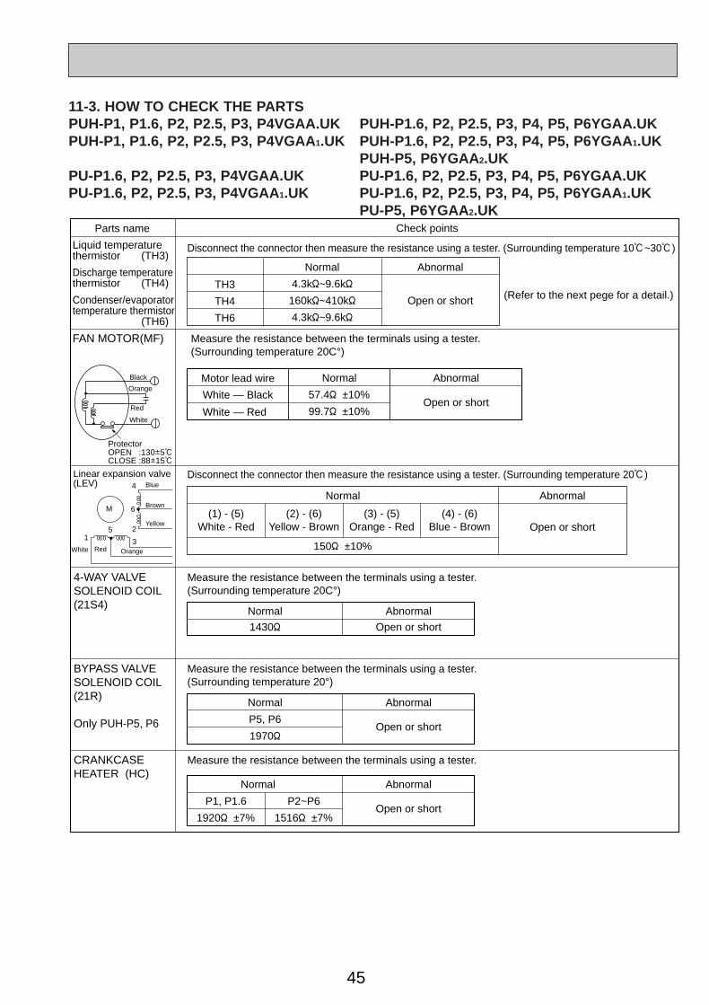
45
M
4
6
2
3
51
Blue
Brown
Yellow
OrangeRedWhite
Linear expansion valve(LEV)
Parts name Check points
Disconnect the connector then measure the resistance using a tester. (Surrounding temperature 10:~30:)
Disconnect the connector then measure the resistance using a tester. (Surrounding temperature 20:)
(Refer to the next pege for a detail.)
Liquid temperature thermistor (TH3)
Discharge temperature thermistor (TH4)
Condenser/evaporatortemperature thermistor (TH6)
Normal
4.3k"~9.6k"
160k"~410k"
4.3k"~9.6k"
TH3
TH4
TH6
Abnormal
Open or short
Measure the resistance between the terminals using a tester.(Surrounding temperature 20C°)
4-WAY VALVE SOLENOID COIL (21S4)
Normal
1430"
Normal
(1) - (5)White - Red
(2) - (6)Yellow - Brown
(3) - (5)Orange - Red
(4) - (6)Blue - Brown
Abnormal
Abnormal
150" ±10%
Open or short
Open or short
Measure the resistance between the terminals using a tester.(Surrounding temperature 20°)
BYPASS VALVE SOLENOID COIL (21R)
Only PUH-P5, P6
Normal
P5, P6
1970"
P1, P1.6
1920" ±7%
P2~P6
1516" ±7%
Abnormal
Open or short
Measure the resistance between the terminals using a tester.CRANKCASE HEATER (HC)
Normal Abnormal
Open or short
Measure the resistance between the terminals using a tester.(Surrounding temperature 20C°)
FAN MOTOR(MF)
Normal
57.4" ±10%
99.7" ±10%
Motor lead wire Abnormal
Open or shortWhite — Black
White — RedRed
Black
White
Orange
ProtectorOPEN :130i5:CLOSE :88i15:
11-3. HOW TO CHECK THE PARTSPUH-P1, P1.6, P2, P2.5, P3, P4VGAA.UK PUH-P1.6, P2, P2.5, P3, P4, P5, P6YGAA.UKPUH-P1, P1.6, P2, P2.5, P3, P4VGAA1.UK PUH-P1.6, P2, P2.5, P3, P4, P5, P6YGAA 1.UK
PUH-P5, P6YGAA2.UKPU-P1.6, P2, P2.5, P3, P4VGAA.UK PU-P1.6, P2, P2.5, P3, P4, P5, P6YGAA.UKPU-P1.6, P2, P2.5, P3, P4VGAA 1.UK PU-P1.6, P2, P2.5, P3, P4, P5, P6YGAA 1.UK
PU-P5, P6YGAA2.UK
OC261-D--2.qxp 05.2.18 11:13 AM Page 45
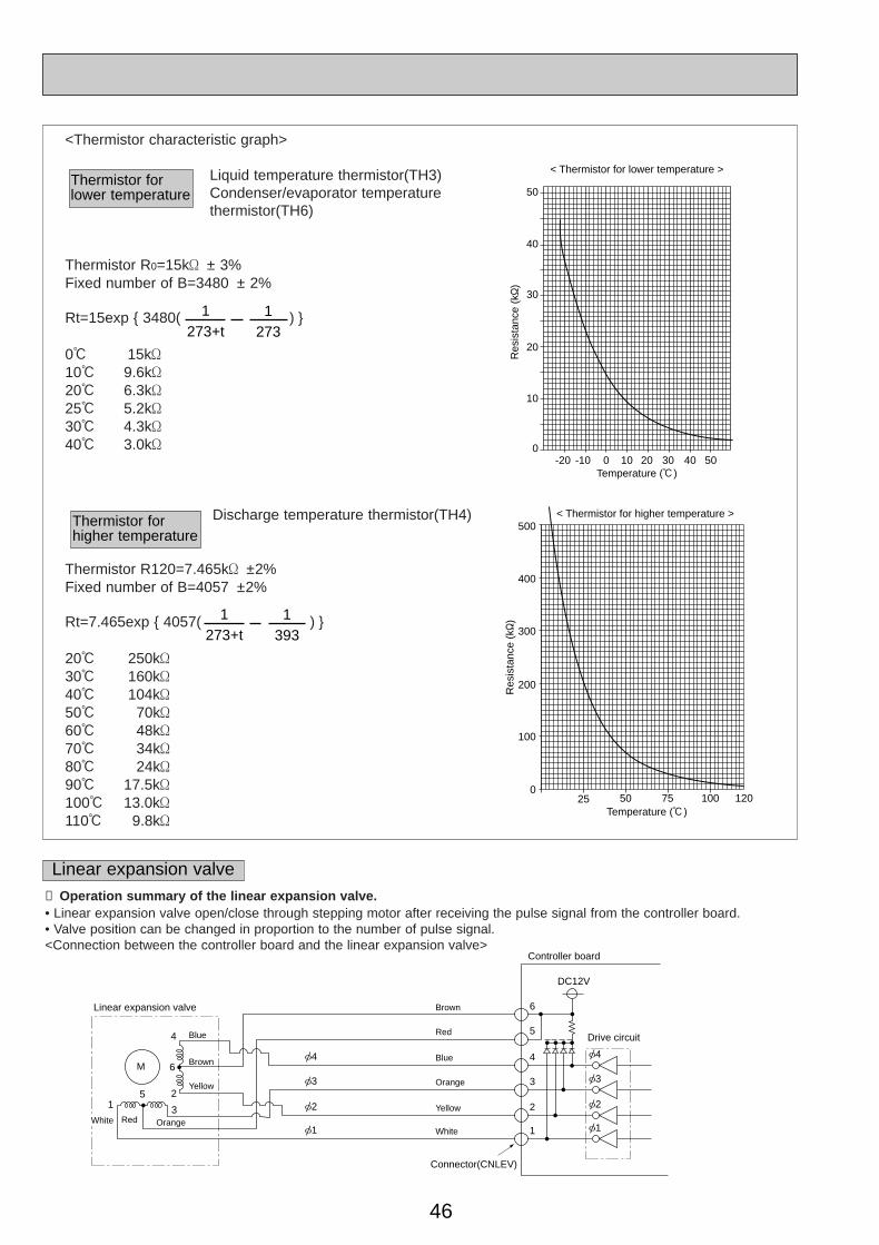
46
4 [4
3
6
5
[3
2 [2
1 [1
[4
[3
[2
[1
Controller board
Drive circuit
Connector(CNLEV)
DC12V
Brown
Red
Blue
Orange
Yellow
White
M
4
6
2
3
51
Blue
Brown
Yellow
OrangeRedWhite
Linear expansion valve
Linear expansion valve① Operation summary of the linear expansion valve.• Linear expansion valve open/close through stepping motor after receiving the pulse signal from the controller board.• Valve position can be changed in proportion to the number of pulse signal.<Connection between the controller board and the linear expansion valve>
0
10
20
30
40
50
-20 -10 0 10 20 30 40 50
< Thermistor for lower temperature >
Temperature (:)
Res
ista
nce
(k"
)500
400
300
200
100
025 50 75 100 120
< Thermistor for higher temperature >
Temperature (:)
Res
ista
nce
(k"
)
<Thermistor characteristic graph>
Liquid temperature thermistor(TH3)Condenser/evaporator temperature thermistor(TH6)
Thermistor R0=15k' ± 3%Fixed number of B=3480 ± 2%
Rt=15exp { 3480( ) }
0: 15k'10: 9.6k'20: 6.3k'25: 5.2k'30: 4.3k'40: 3.0k'
Discharge temperature thermistor(TH4)
Thermistor R120=7.465k' ±2%Fixed number of B=4057 ±2%
Rt=7.465exp { 4057( ) }
20: 250k'30: 160k'40: 104k'50: 70k'60: 48k'70: 34k'80: 24k'90: 17.5k'100: 13.0k'110: 9.8k'
Thermistor for lower temperature
1273+t
1273
1273+t
1393
Thermistor for higher temperature
OC261-D--2.qxp 05.2.18 11:13 AM Page 46
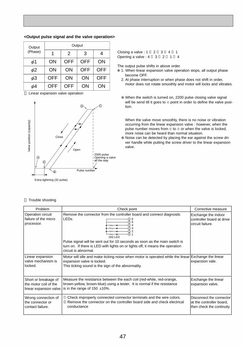
47
➂ Trouble shooting
Problem Check point Corrective measureRemove the connector from the controller board and connect diagnostic LEDs.
Pulse signal will be sent out for 10 seconds as soon as the main switch is turn on. If there is LED with lights on or lights off, it means the operation circuit is abnormal.
Motor will idle and make ticking noise when motor is operated while the linear expansion valve is locked. This ticking sound is the sign of the abnormality.
Measure the resistance between the each coil (red-white, red-orange, brown-yellow, brown-blue) using a tester. It is normal if the resistance is in the range of 150’ ±10%.
1 Check improperly connected connector terminals and the wire colors. 2 Remove the connector on the controller board side and check electrical conductance
Operation circuit failure of the micro processor.
Exchange the linear expansion valve.
Exchange the indoor controller board at drive circuit failure.
Exchange the linear expansion vale.
Disconnect the connector at the controller board, then check the continuity.
Wrong connection of the connector or contact failure.
Short or breakage of the motor coil of the linear expansion valve.
Linear expansion valve mechanism is locked.
654321
1k" LED
Output(Phase)
Output
{1
1
ON
{2 ON
{3 OFF
{4 OFF
2
OFF
ON
ON
OFF
3
OFF
OFF
ON
ON
4
ON
OFF
OFF
ON
<Output pulse signal and the valve operation>
➁ Linear expansion valve operation
D
A
E
B
C
Open
Extra tightning (32 pulse)
Pulse number
2000 pulseOpening a valveall the way
Close
Val
ve p
ositi
on (
capa
city
)
Closing a valve : 1 → 2 → 3 → 4 → 1Opening a valve : 4 → 3 → 2 → 1 → 4
The output pulse shifts in above order.❈ 1. When linear expansion valve operation stops, all output phase
become OFF.2. At phase interruption or when phase does not shift in order,
motor does not rotate smoothly and motor will locks and vibrates.
❈ When the switch is turned on, 2200 pulse closing valve signalwill be send till it goes to A point in order to define the valve posi-tion.
When the valve move smoothly, there is no noise or vibrationoccurring from the linear expansion valve : however, when thepulse number moves from E to A or when the valve is locked,more noise can be heard than normal situation.
❈ Noise can be detected by placing the ear against the screw dri-ver handle while putting the screw driver to the linear expansionvalve.
OC261-D--2.qxp 05.2.18 11:13 AM Page 47
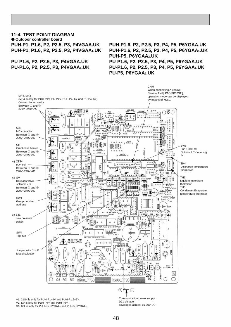
48
Jumper wire J1~J6Model selection
SW1Group numberaddress
SW4Test run
SW5Fan 100% fixOutdoor LEV openingfix
TH4Discharge temperaturethermistor
TH3Liquid temperaturethermisorTH6Condenser/Evaporator temperature thermisor
CNMWhen connecting A-controlService Tool [ PAC-SK52ST ],operation mode can be displayedby means of 7SEG
Communication power supply D71 Voltage developed across: 16-30V DC
–+
52CMC contactorBetween 1 and 3220V~240V AC
CHCrankcase heaterBetween 1 and 3220V~240V AC
21S4R.V. coilBetween 1 and 3220V~240V AC
SVBaypass valvesolenoid coilBetween 1 and 3220V~240V AC
MF4, MF3(MF4 is only for PUH-P4V, PU-P4V, PUH-P4~6Y and PU-P4~6Y)Connect to fan motorBetween 1 and 3220V~240V AC
w2
w1
w1. 21S4 is only for PUH-P1~4V and PUH-P1.6~6Y.w2. SV is only for PUH-P5Y and PUH-P6Y. w3. 63L is only for PUH-P5, 6YGAA2 and PU-P5, 6YGAA2.
63LLow pressure switch
w3
11-4. TEST POINT DIAGRAM● Outdoor controller boardPUH-P1, P1.6, P2, P2.5, P3, P4VGAA.UK PUH-P1.6, P2, P2.5, P3, P4, P5, P6YGAA.UKPUH-P1, P1.6, P2, P2.5, P3, P4VGAA 1.UK PUH-P1.6, P2, P2.5, P3, P4, P5, P6YGAA 1.UK
PUH-P5, P6YGAA2.UKPU-P1.6, P2, P2.5, P3, P4VGAA.UK PU-P1.6, P2, P2.5, P3, P4, P5, P6YGAA.UKPU-P1.6, P2, P2.5, P3, P4VGAA 1.UK PU-P1.6, P2, P2.5, P3, P4, P5, P6YGAA 1.UK
PU-P5, P6YGAA2.UK
OC261-D--2.qxp 05.2.18 11:13 AM Page 48
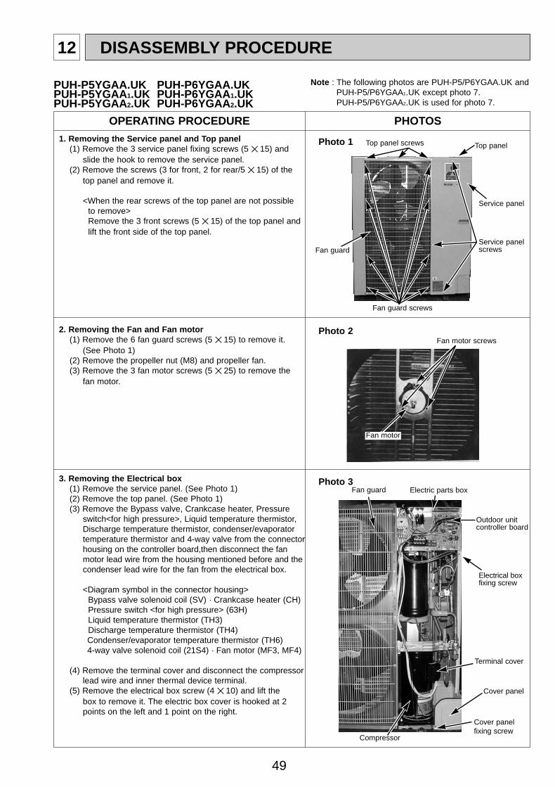
49
12 DISASSEMBLY PROCEDURE
OPERATING PROCEDURE PHOTOS
1. Removing the Service panel and Top panel(1) Remove the 3 service panel fixing screws (5 ✕ 15) and
slide the hook to remove the service panel.(2) Remove the screws (3 for front, 2 for rear/5 ✕ 15) of the
top panel and remove it.
<When the rear screws of the top panel are not possibleto remove>Remove the 3 front screws (5 ✕ 15) of the top panel andlift the front side of the top panel.
Photo 1 Top panel screws Top panel
Service panelscrews
Service panel
Fan guard screws
Fan guard
2. Removing the Fan and Fan motor(1) Remove the 6 fan guard screws (5 ✕ 15) to remove it.
(See Photo 1)(2) Remove the propeller nut (M8) and propeller fan.(3) Remove the 3 fan motor screws (5 ✕ 25) to remove the
fan motor.
Fan motor screws
Fan motor
Photo 33. Removing the Electrical box(1) Remove the service panel. (See Photo 1)(2) Remove the top panel. (See Photo 1)(3) Remove the Bypass valve, Crankcase heater, Pressure
switch<for high pressure>, Liquid temperature thermistor,Discharge temperature thermistor, condenser/evaporatortemperature thermistor and 4-way valve from the connectorhousing on the controller board,then disconnect the fanmotor lead wire from the housing mentioned before and thecondenser lead wire for the fan from the electrical box.
<Diagram symbol in the connector housing>Bypass valve solenoid coil (SV) · Crankcase heater (CH)Pressure switch <for high pressure> (63H)Liquid temperature thermistor (TH3)Discharge temperature thermistor (TH4)Condenser/evaporator temperature thermistor (TH6)4-way valve solenoid coil (21S4) · Fan motor (MF3, MF4)
(4) Remove the terminal cover and disconnect the compressorlead wire and inner thermal device terminal.
(5) Remove the electrical box screw (4 ✕ 10) and lift thebox to remove it. The electric box cover is hooked at 2points on the left and 1 point on the right.
Fan guard Electric parts box
Outdoor unitcontroller board
Electrical boxfixing screw
Terminal cover
Cover panel
Cover panel fixing screw
Photo 2
PUH-P5YGAA.UK PUH-P6YGAA.UKPUH-P5YGAA1.UK PUH-P6YGAA 1.UKPUH-P5YGAA2.UK PUH-P6YGAA 2.UK
Compressor
Note : The following photos are PUH-P5/P6YGAA.UK and PUH-P5/P6YGAA1.UK except photo 7. PUH-P5/P6YGAA2.UK is used for photo 7.
OC261-D--2.qxp 05.2.18 11:13 AM Page 49
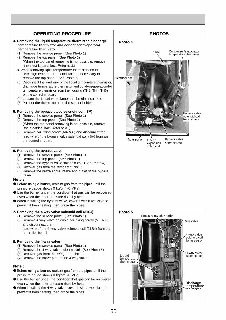
50
OPERATING PROCEDURE PHOTOS
Photo 44. Removing the liquid temperature thermistor, discharge temperature thermistor and condenser/evaporator temperature thermistor(1) Remove the service panel. (See Photo 1)(2) Remove the top panel. (See Photo 1)
(When the top panel removing is not possible, removethe electric parts box. Refer to 3.)
w When removing liquid temperature thermistor and thedischarge temperature thermistor, it unnecessary toremove the top panel. (See Photo 5)
(3) Disconnect the lead wire of the liquid temperature thermistor,discharge temperature thermistor and condenser/evaporatortemperature thermistor from the housing (TH3, TH4, TH6)on the controller board.
(4) Loosen the 1 lead wire clamps on the electrical box.(5) Pull out the thermistor from the sensor holder.
5. Removing the bypass valve solenoid coil (SV)(1) Remove the service panel. (See Photo 1)(2) Remove the top panel. (See Photo 1)
(When the top panel removing is not possible, removethe electrical box. Refer to 3. )
(3) Remove coil fixing screw (M4 ✕ 8) and disconnect thelead wire of the bypass valve solenoid coil (SV) from on the controller board.
8. Removing the 4-way valve(1) Remove the service panel. (See Photo 1)(2) Remove the 4-way valve solenoid coil. (See Photo 5)(3) Recover gas from the refrigerant circuit.(4) Remove the braze pipe of the 4-way valve.
Note :● Before using a burner, reclaim gas from the pipes until the
pressure gauge shows 0 kg/cm2 (0 MPa).● Use the burner under the condition that gas can be recovered
even when the inner pressure rises by heat.● When installing the 4-way valve, cover it with a wet cloth to
prevent it from heating, then braze the pipes.
6. Removing the bypass valve(1) Remove the service panel. (See Photo 1)(2) Remove the top panel. (See Photo 1)(3) Remove the bypass valve solenoid coil. (See Photo 4)(4) Recover gas from the refrigerant circuit.(5) Remove the braze at the intake and outlet of the bypass
valve.Note :● Before using a burner, reclaim gas from the pipes until the
pressure gauge shows 0 kg/cm2 (0 MPa).● Use the burner under the condition that gas can be recovered
even when the inner pressure rises by heat.● When installing the bypass valve, cover it with a wet cloth to
prevent it from heating, then braze the pipes.
Photo 5
Clamp
Bypass valvesolenoid coilfixing screw
Rear panel
Condenser/evaporatortemperature thermistor
4-way valvesolenoid coil
4-way valvesolenoid coilfixing screw
4-way valve
Pressure switch <High>
Liquidtemperaturethermistor
Dischargetemperaturethermistor
7. Removing the 4-way valve solenoid coil (21S4)(1) Remove the service panel. (See Photo 1)(2) Remove 4-way valve solenoid coil fixing screw (M5 ✕ 6)
and disconnect the lead wire of the 4-way valve solenoid coil (21S4) from the controller board.
Linearexpansionvalve coil
Bypass valvesolenoid coil
Electrical box
OC261-D--2.qxp 05.2.18 11:13 AM Page 50
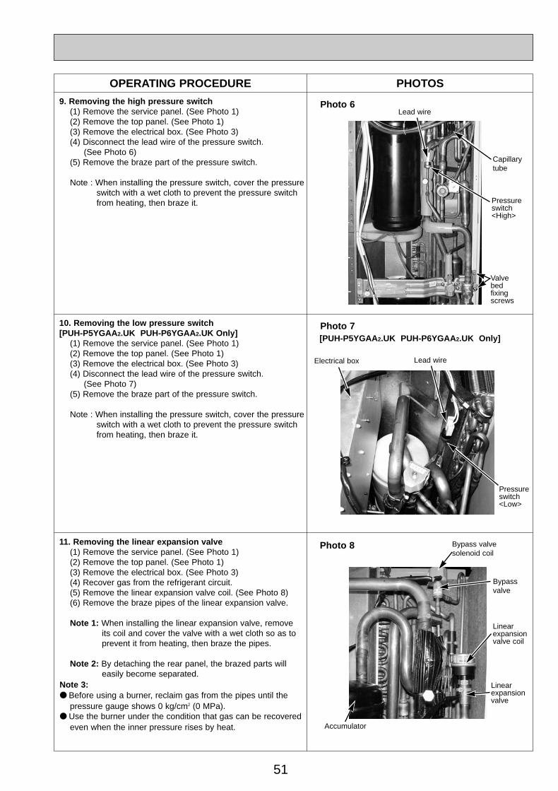
51
OPERATING PROCEDURE PHOTOS
9. Removing the high pressure switch(1) Remove the service panel. (See Photo 1)(2) Remove the top panel. (See Photo 1)(3) Remove the electrical box. (See Photo 3)(4) Disconnect the lead wire of the pressure switch.
(See Photo 6)(5) Remove the braze part of the pressure switch.
Note : When installing the pressure switch, cover the pressureswitch with a wet cloth to prevent the pressure switchfrom heating, then braze it.
11. Removing the linear expansion valve(1) Remove the service panel. (See Photo 1)(2) Remove the top panel. (See Photo 1)(3) Remove the electrical box. (See Photo 3)(4) Recover gas from the refrigerant circuit.(5) Remove the linear expansion valve coil. (See Photo 8) (6) Remove the braze pipes of the linear expansion valve.
Note 1: When installing the linear expansion valve, removeits coil and cover the valve with a wet cloth so as toprevent it from heating, then braze the pipes.
Note 2: By detaching the rear panel, the brazed parts willeasily become separated.
Note 3:● Before using a burner, reclaim gas from the pipes until the
pressure gauge shows 0 kg/cm2 (0 MPa).● Use the burner under the condition that gas can be recovered
even when the inner pressure rises by heat.
Photo 6
Pressure switch <High>
Capillarytube
Valvebedfixingscrews
Lead wire
Photo 8
Linearexpansionvalve coil
Linearexpansionvalve
Bypass valve
Bypass valvesolenoid coil
Accumulator
10. Removing the low pressure switch[PUH-P5YGAA 2.UK PUH-P6YGAA 2.UK Only]
(1) Remove the service panel. (See Photo 1)(2) Remove the top panel. (See Photo 1)(3) Remove the electrical box. (See Photo 3)(4) Disconnect the lead wire of the pressure switch.
(See Photo 7)(5) Remove the braze part of the pressure switch.
Note : When installing the pressure switch, cover the pressureswitch with a wet cloth to prevent the pressure switchfrom heating, then braze it.
Photo 7
Pressure switch <Low>
Lead wireElectrical box
[PUH-P5YGAA 2.UK PUH-P6YGAA 2.UK Only]
OC261-D--2.qxp 05.2.18 11:13 AM Page 51
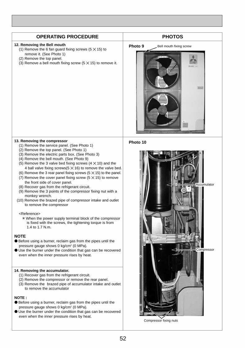
52
OPERATING PROCEDURE PHOTOS
13. Removing the compressor(1) Remove the service panel. (See Photo 1)(2) Remove the top panel. (See Photo 1)(3) Remove the electric parts box. (See Photo 3)(4) Remove the bell mouth. (See Photo 9)(5) Remove the 3 valve bed fixing screws (4 ✕ 10) and the
4 ball valve fixing screws(5 ✕ 16) to remove the valve bed.(6) Remove the 3 rear panel fixing screws (5 ✕ 15) to the panel.(7) Remove the cover panel fixing screw (5 ✕ 15) to remove
the front side of cover panel.(8) Recover gas from the refrigerant circuit.(9) Remove the 3 points of the compressor fixing nut with a
monkey wrench.(10) Remove the brazed pipe of compressor intake and outlet
to remove the compressor
<Reference>w When the power supply terminal block of the compressor
is fixed with the screws, the tightening torque is from 1.4 to 1.7 N.m.
NOTE● Before using a burner, reclaim gas from the pipes until the
pressure gauge shows 0 kg/cm2 (0 MPa).● Use the burner under the condition that gas can be recovered
even when the inner pressure rises by heat.
14. Removing the accumulator.(1) Recover gas from the refrigerant circuit.(2) Remove the compressor or remove the rear panel.(3) Remove the brazed pipe of accumulator intake and outlet
to remove the accumulator
NOTE :● Before using a burner, reclaim gas from the pipes until the
pressure gauge shows 0 kg/cm2 (0 MPa).● Use the burner under the condition that gas can be recovered
even when the inner pressure rises by heat.
Photo 10
Compressor fixing nuts
Compressor
Accumulator
12. Removing the Bell mouth(1) Remove the 6 fan guard fixing screws (5 ✕ 15) to
remove it. (See Photo 1)(2) Remove the top panel.(3) Remove a bell mouth fixing screw (5 ✕ 15) to remove it.
Bell mouth fixing screwPhoto 9
OC261-D--2.qxp 05.2.18 11:13 AM Page 52
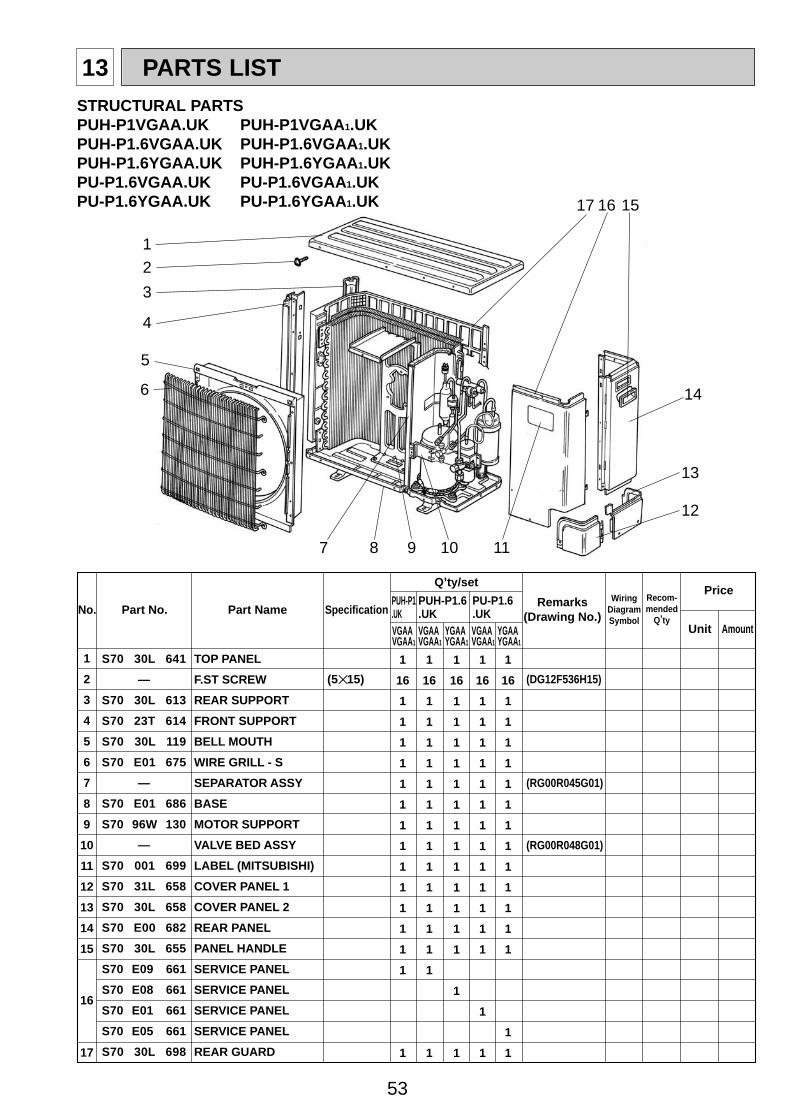
53
13 PARTS LIST
Part No. SpecificationNo.Wiring
DiagramSymbol
Recom-mended
Q,ty
Price
Unit Amount
Part Name
Q,ty/set
PUH-P1.UK
PUH-P1.6.UK
PU-P1.6.UK
VGAAVGAA1
VGAAVGAA1
YGAAYGAA1
VGAAVGAA1
YGAAYGAA1
Remarks(Drawing No.)
1
2
3
4
5
6
7
8
9
10
11
12
13
14
15
16
17
1
16
1
1
1
1
1
1
1
1
1
1
1
1
1
1
1
1
16
1
1
1
1
1
1
1
1
1
1
1
1
1
1
1
(DG12F536H15)
(RG00R045G01)
(RG00R048G01)
1
16
1
1
1
1
1
1
1
1
1
1
1
1
1
1
1
1
16
1
1
1
1
1
1
1
1
1
1
1
1
1
1
1
1
16
1
1
1
1
1
1
1
1
1
1
1
1
1
1
1
(5✕15)
S70 30L 641
—
S70 30L 613
S70 23T 614
S70 30L 119
S70 E01 675
—
S70 E01 686
S70 96W 130
—
S70 001 699
S70 31L 658
S70 30L 658
S70 E00 682
S70 30L 655
S70 E09 661
S70 E08 661
S70 E01 661
S70 E05 661
S70 30L 698
TOP PANEL
F.ST SCREW
REAR SUPPORT
FRONT SUPPORT
BELL MOUTH
WIRE GRILL - S
SEPARATOR ASSY
BASE
MOTOR SUPPORT
VALVE BED ASSY
LABEL (MITSUBISHI)
COVER PANEL 1
COVER PANEL 2
REAR PANEL
PANEL HANDLE
SERVICE PANEL
SERVICE PANEL
SERVICE PANEL
SERVICE PANEL
REAR GUARD
1
17
2
4
7 8 11
12
5
6
16
14
15
3
13
9 10
STRUCTURAL PARTSPUH-P1VGAA.UK PUH-P1VGAA 1.UK PUH-P1.6VGAA.UK PUH-P1.6VGAA 1.UK PUH-P1.6YGAA.UK PUH-P1.6YGAA 1.UK PU-P1.6VGAA.UK PU-P1.6VGAA 1.UK PU-P1.6YGAA.UK PU-P1.6YGAA 1.UK
OC261-D--2.qxp 05.2.18 11:13 AM Page 53
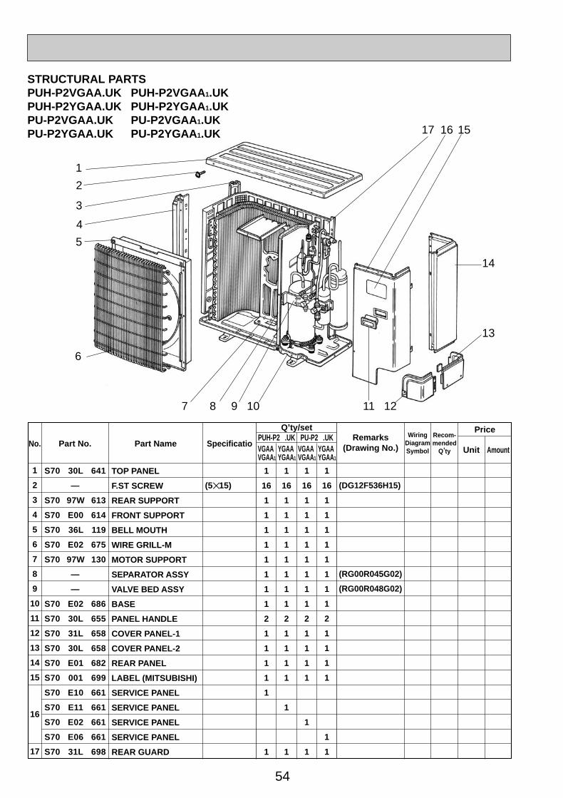
54
Part No. Part Name SpecificatioNo.Wiring
DiagramSymbol
Recom-mended
Q,ty
Q,ty/set
VGAAVGAA1
YGAAYGAA1
VGAAVGAA1
YGAAYGAA1
1
2
3
4
5
6
7
8
9
10
11
12
13
14
15
16
17
TOP PANEL
F.ST SCREW
REAR SUPPORT
FRONT SUPPORT
BELL MOUTH
WIRE GRILL-M
MOTOR SUPPORT
SEPARATOR ASSY
VALVE BED ASSY
BASE
PANEL HANDLE
COVER PANEL-1
COVER PANEL-2
REAR PANEL
LABEL (MITSUBISHI)
SERVICE PANEL
SERVICE PANEL
SERVICE PANEL
SERVICE PANEL
REAR GUARD
(5✕15)
AmountUnit
PriceRemarks
(Drawing No.)
(DG12F536H15)
(RG00R045G02)
(RG00R048G02)
S70 30L 641
—
S70 97W 613
S70 E00 614
S70 36L 119
S70 E02 675
S70 97W 130
—
—
S70 E02 686
S70 30L 655
S70 31L 658
S70 30L 658
S70 E01 682
S70 001 699
S70 E10 661
S70 E11 661
S70 E02 661
S70 E06 661
S70 31L 698
1
16
1
1
1
1
1
1
1
1
2
1
1
1
1
1
1
1
16
1
1
1
1
1
1
1
1
2
1
1
1
1
1
1
1
16
1
1
1
1
1
1
1
1
2
1
1
1
1
1
1
1
16
1
1
1
1
1
1
1
1
2
1
1
1
1
1
1
PUH-P2 .UK PU-P2 .UK
1
17
2
7 8 11 12
5
6
16
14
15
13
4
3
9 10
STRUCTURAL PARTSPUH-P2VGAA.UK PUH-P2VGAA 1.UKPUH-P2YGAA.UK PUH-P2YGAA 1.UKPU-P2VGAA.UK PU-P2VGAA 1.UKPU-P2YGAA.UK PU-P2YGAA 1.UK
OC261-D--2.qxp 05.2.18 11:13 AM Page 54
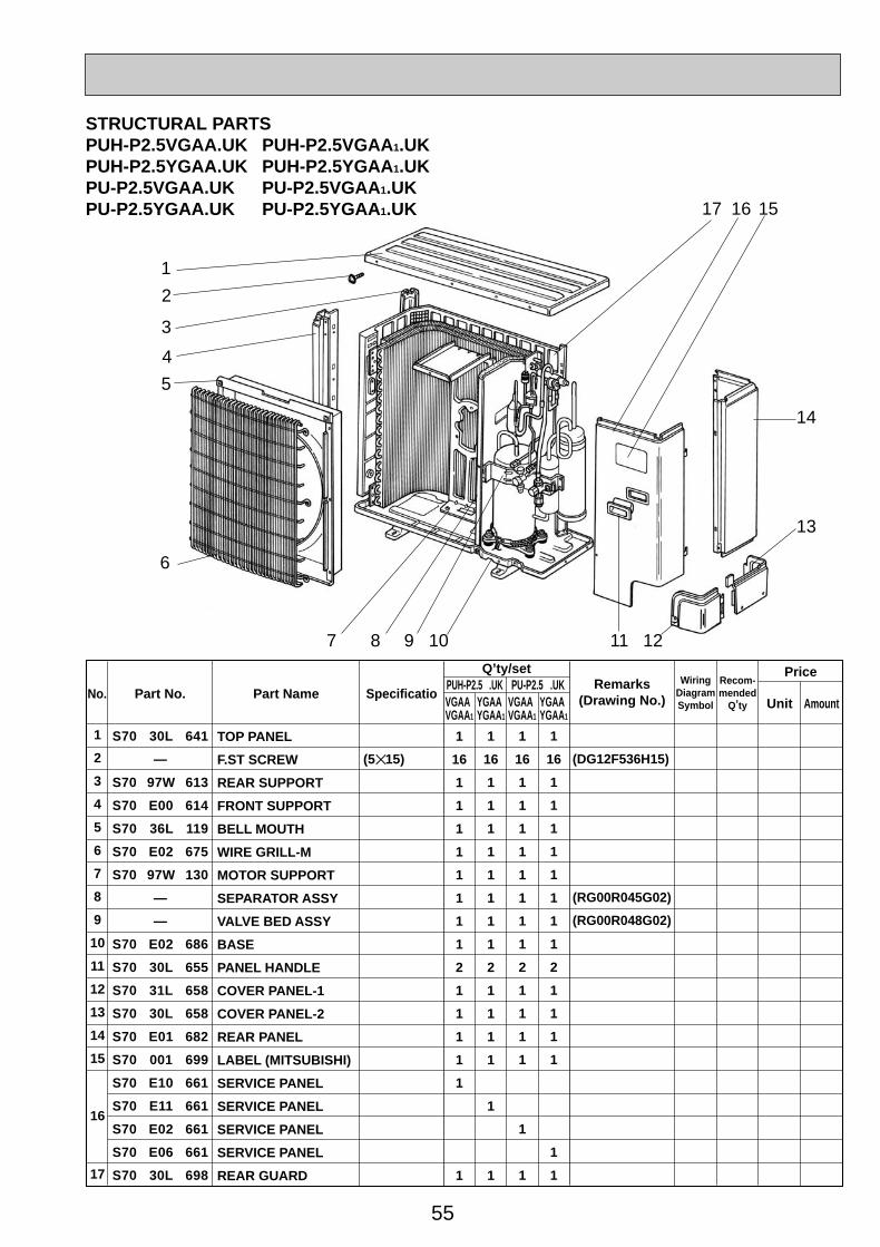
55
Part No. Part Name SpecificatioNo.Wiring
DiagramSymbol
Recom-mended
Q,ty
Q,ty/set
VGAAVGAA1
YGAAYGAA1
VGAAVGAA1
YGAAYGAA1
1
2
3
4
5
6
7
8
9
10
11
12
13
14
15
16
17
TOP PANEL
F.ST SCREW
REAR SUPPORT
FRONT SUPPORT
BELL MOUTH
WIRE GRILL-M
MOTOR SUPPORT
SEPARATOR ASSY
VALVE BED ASSY
BASE
PANEL HANDLE
COVER PANEL-1
COVER PANEL-2
REAR PANEL
LABEL (MITSUBISHI)
SERVICE PANEL
SERVICE PANEL
SERVICE PANEL
SERVICE PANEL
REAR GUARD
(5✕15)
AmountUnit
PriceRemarks
(Drawing No.)
(DG12F536H15)
(RG00R045G02)
(RG00R048G02)
S70 30L 641
—
S70 97W 613
S70 E00 614
S70 36L 119
S70 E02 675
S70 97W 130
—
—
S70 E02 686
S70 30L 655
S70 31L 658
S70 30L 658
S70 E01 682
S70 001 699
S70 E10 661
S70 E11 661
S70 E02 661
S70 E06 661
S70 30L 698
1
16
1
1
1
1
1
1
1
1
2
1
1
1
1
1
1
1
16
1
1
1
1
1
1
1
1
2
1
1
1
1
1
1
1
16
1
1
1
1
1
1
1
1
2
1
1
1
1
1
1
1
16
1
1
1
1
1
1
1
1
2
1
1
1
1
1
1
PUH-P2.5 .UK PU-P2.5 .UK
1
17
2
7 8 11 12
5
6
16
14
15
13
4
3
9 10
STRUCTURAL PARTSPUH-P2.5VGAA.UK PUH-P2.5VGAA 1.UKPUH-P2.5YGAA.UK PUH-P2.5YGAA 1.UKPU-P2.5VGAA.UK PU-P2.5VGAA 1.UKPU-P2.5YGAA.UK PU-P2.5YGAA 1.UK
OC261-D--2.qxp 05.2.18 11:13 AM Page 55
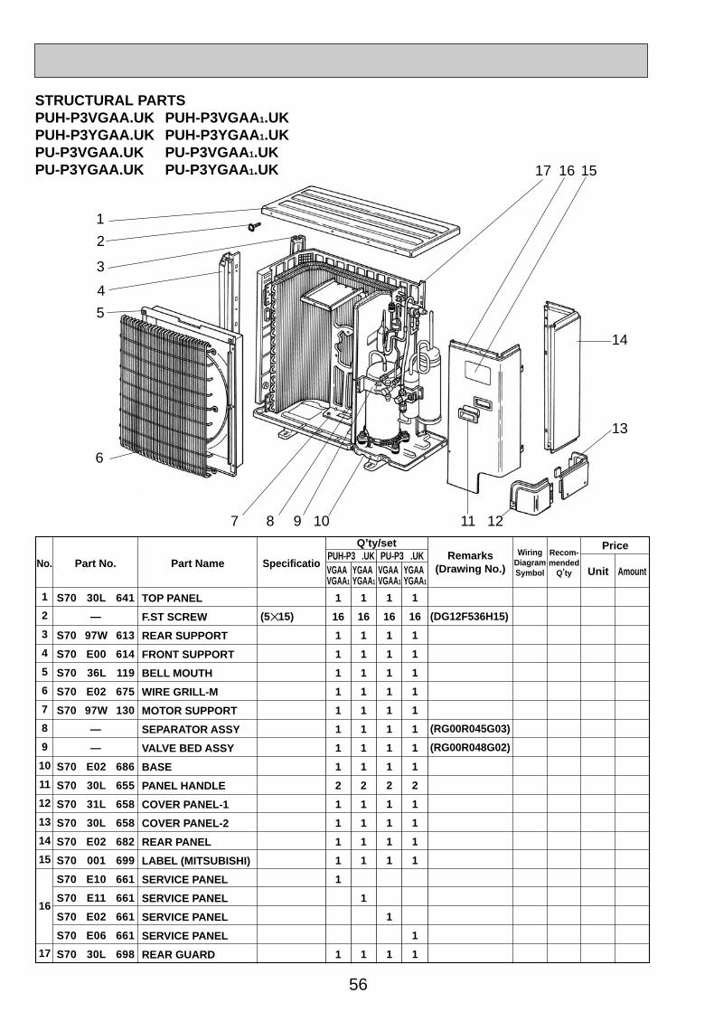
56
Part No. Part Name SpecificatioNo.Wiring
DiagramSymbol
Recom-mended
Q,ty
Q,ty/set
VGAAVGAA1
YGAAYGAA1
VGAAVGAA1
YGAAYGAA1
1
2
3
4
5
6
7
8
9
10
11
12
13
14
15
16
17
TOP PANEL
F.ST SCREW
REAR SUPPORT
FRONT SUPPORT
BELL MOUTH
WIRE GRILL-M
MOTOR SUPPORT
SEPARATOR ASSY
VALVE BED ASSY
BASE
PANEL HANDLE
COVER PANEL-1
COVER PANEL-2
REAR PANEL
LABEL (MITSUBISHI)
SERVICE PANEL
SERVICE PANEL
SERVICE PANEL
SERVICE PANEL
REAR GUARD
(5✕15)
AmountUnit
PriceRemarks
(Drawing No.)
(DG12F536H15)
(RG00R045G03)
(RG00R048G02)
S70 30L 641
—
S70 97W 613
S70 E00 614
S70 36L 119
S70 E02 675
S70 97W 130
—
—
S70 E02 686
S70 30L 655
S70 31L 658
S70 30L 658
S70 E02 682
S70 001 699
S70 E10 661
S70 E11 661
S70 E02 661
S70 E06 661
S70 30L 698
1
16
1
1
1
1
1
1
1
1
2
1
1
1
1
1
1
1
16
1
1
1
1
1
1
1
1
2
1
1
1
1
1
1
1
16
1
1
1
1
1
1
1
1
2
1
1
1
1
1
1
1
16
1
1
1
1
1
1
1
1
2
1
1
1
1
1
1
PUH-P3 .UK PU-P3 .UK
1
17
2
7 8 11 12
5
6
16
14
15
13
4
3
9 10
STRUCTURAL PARTSPUH-P3VGAA.UK PUH-P3VGAA 1.UKPUH-P3YGAA.UK PUH-P3YGAA 1.UKPU-P3VGAA.UK PU-P3VGAA 1.UKPU-P3YGAA.UK PU-P3YGAA 1.UK
OC261-D--2.qxp 05.2.18 11:13 AM Page 56
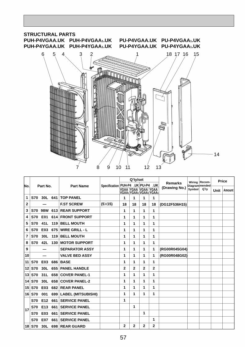
57
Part No. Part Name SpecificationNo.Wiring
DiagramSymbol
Recom-mended
Q,ty
Price
Unit Amount
(5✕15)
PUH-P4 .UK PU-P4 .UK Remarks(Drawing No.)
1
2
3
4
5
6
7
8
9
10
11
12
13
14
15
16
17
18
1
18
1
1
1
1
1
1
1
1
1
2
1
1
1
1
1
2
1
18
1
1
1
1
1
1
1
1
1
2
1
1
1
1
1
2
1
18
1
1
1
1
1
1
1
1
1
2
1
1
1
1
1
2
1
18
1
1
1
1
1
1
1
1
1
2
1
1
1
1
1
2
(DG12F536H15)
(RG00R045G04)
(RG00R048G02)
S70 30L 641
—
S70 98W 613
S70 E01 614
S70 41L 119
S70 E03 675
S70 30L 119
S70 42L 130
—
—
S70 E03 686
S70 30L 655
S70 31L 658
S70 30L 658
S70 E03 682
S70 001 699
S70 E12 661
S70 E13 661
S70 E03 661
S70 E07 661
S70 30L 698
TOP PANEL
F.ST SCREW
REAR SUPPORT
FRONT SUPPORT
BELL MOUTH
WIRE GRILL - L
BELL MOUTH
MOTOR SUPPORT
SEPARATOR ASSY
VALVE BED ASSY
BASE
PANEL HANDLE
COVER PANEL-1
COVER PANEL-2
REAR PANEL
LABEL (MITSUBISHI)
SERVICE PANEL
SERVICE PANEL
SERVICE PANEL
SERVICE PANEL
REAR GUARD
Q,ty/set
VGAAVGAA1
YGAAYGAA1
VGAAVGAA1
YGAAYGAA1
13 1824
7
6 16 15
14
175
8 9 10 11 12 13
STRUCTURAL PARTSPUH-P4VGAA.UK PUH-P4VGAA 1.UK PU-P4VGAA.UK PU-P4VGAA 1.UKPUH-P4YGAA.UK PUH-P4YGAA 1.UK PU-P4YGAA.UK PU-P4YGAA 1.UK
OC261-D--2.qxp 05.2.18 11:13 AM Page 57
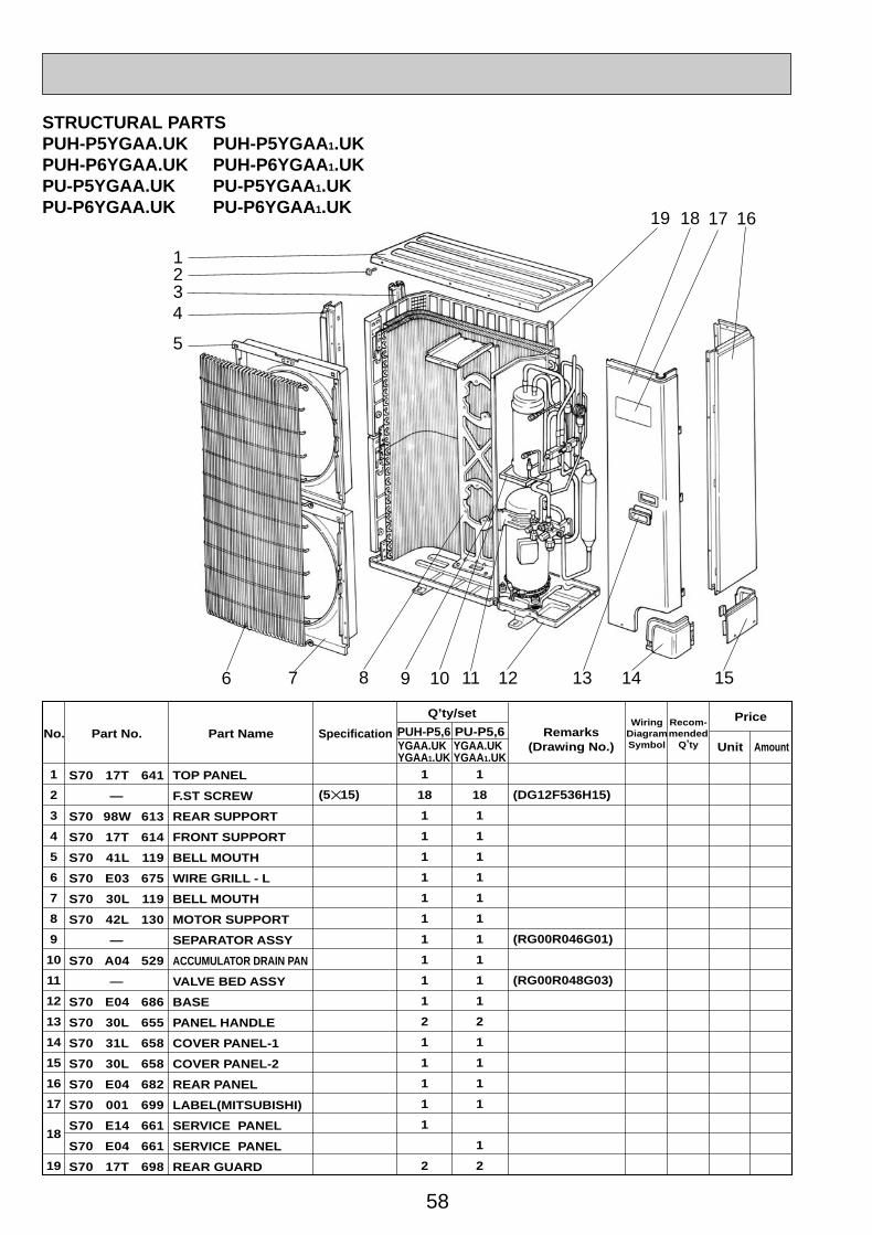
58
Part No. Part Name SpecificationNo.Wiring
DiagramSymbol
Recom-mended
Q,ty
Price
Unit Amount
(5✕15)
Q,ty/set
Remarks(Drawing No.)
PUH-P5,6 PU-P5,6
1
2
3
4
5
6
7
8
9
10
11
12
13
14
15
16
17
18
19
1
18
1
1
1
1
1
1
1
1
1
1
2
1
1
1
1
1
2
1
18
1
1
1
1
1
1
1
1
1
1
2
1
1
1
1
1
2
(DG12F536H15)
(RG00R046G01)
(RG00R048G03)
YGAA.UKYGAA1.UK
YGAA.UKYGAA1.UK
S70 17T 641
—
S70 98W 613
S70 17T 614
S70 41L 119
S70 E03 675
S70 30L 119
S70 42L 130
—
S70 A04 529
—
S70 E04 686
S70 30L 655
S70 31L 658
S70 30L 658
S70 E04 682
S70 001 699
S70 E14 661
S70 E04 661
S70 17T 698
TOP PANEL
F.ST SCREW
REAR SUPPORT
FRONT SUPPORT
BELL MOUTH
WIRE GRILL - L
BELL MOUTH
MOTOR SUPPORT
SEPARATOR ASSY
ACCUMULATOR DRAIN PAN
VALVE BED ASSY
BASE
PANEL HANDLE
COVER PANEL-1
COVER PANEL-2
REAR PANEL
LABEL(MITSUBISHI)
SERVICE PANEL
SERVICE PANEL
REAR GUARD
1
1819
2
4
5
12 136
17 16
15
3
1198 107 14
STRUCTURAL PARTSPUH-P5YGAA.UK PUH-P5YGAA 1.UKPUH-P6YGAA.UK PUH-P6YGAA 1.UKPU-P5YGAA.UK PU-P5YGAA 1.UKPU-P6YGAA.UK PU-P6YGAA 1.UK
OC261-D--2.qxp 05.2.18 11:13 AM Page 58
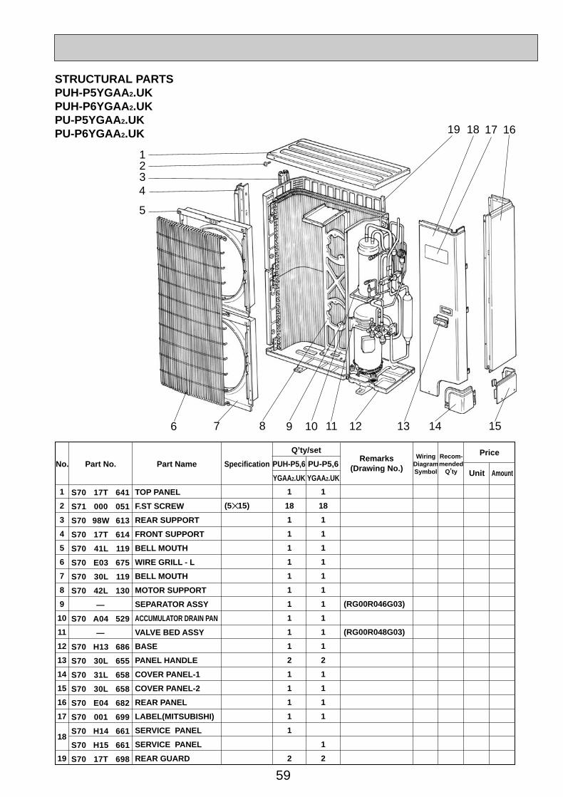
59
Part No. Part Name SpecificationNo.Wiring
DiagramSymbol
Recom-mended
Q,ty
Price
Unit Amount
(5✕15)
Q,ty/setRemarks
(Drawing No.)PUH-P5,6 PU-P5,6
1
2
3
4
5
6
7
8
9
10
11
12
13
14
15
16
17
18
19
1
18
1
1
1
1
1
1
1
1
1
1
2
1
1
1
1
1
2
1
18
1
1
1
1
1
1
1
1
1
1
2
1
1
1
1
1
2
(RG00R046G03)
(RG00R048G03)
YGAA2.UK YGAA2.UK
S70 17T 641
S71 000 051
S70 98W 613
S70 17T 614
S70 41L 119
S70 E03 675
S70 30L 119
S70 42L 130
—
S70 A04 529
—
S70 H13 686
S70 30L 655
S70 31L 658
S70 30L 658
S70 E04 682
S70 001 699
S70 H14 661
S70 H15 661
S70 17T 698
TOP PANEL
F.ST SCREW
REAR SUPPORT
FRONT SUPPORT
BELL MOUTH
WIRE GRILL - L
BELL MOUTH
MOTOR SUPPORT
SEPARATOR ASSY
ACCUMULATOR DRAIN PAN
VALVE BED ASSY
BASE
PANEL HANDLE
COVER PANEL-1
COVER PANEL-2
REAR PANEL
LABEL(MITSUBISHI)
SERVICE PANEL
SERVICE PANEL
REAR GUARD
1
1819
2
4
5
12 136
17 16
15
3
1198 107 14
STRUCTURAL PARTSPUH-P5YGAA2.UKPUH-P6YGAA2.UKPU-P5YGAA2.UKPU-P6YGAA2.UK
OC261-D--2.qxp 05.2.18 11:13 AM Page 59

60
FUNCTIONAL PARTSPUH-P1VGAA.UKPUH-P1VGAA1.UK
15
14
13
12
1
6
18
19
20
2126 2225 2324
7 8 9 10 11
2
4
5
17
16
3
FUSE
OC261-D--2.qxp 05.2.18 11:13 AM Page 60
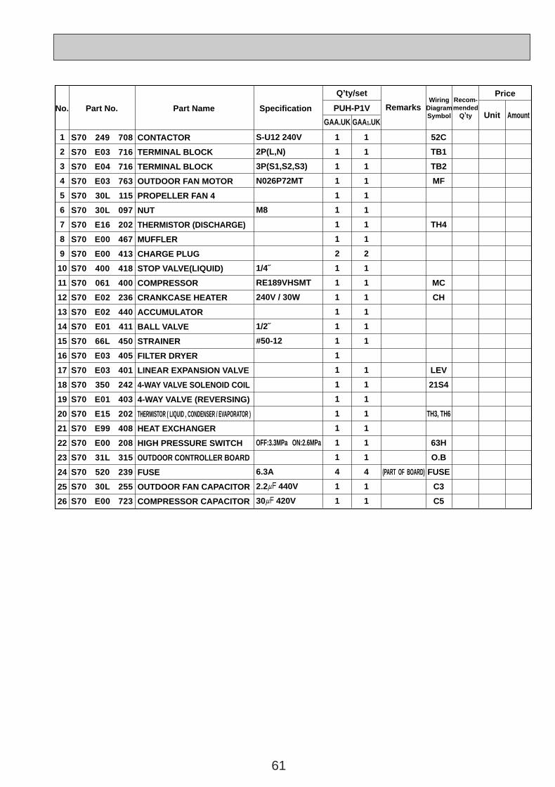
61
Price
Part No. Part Name SpecificationNo.Wiring
DiagramSymbol
Recom-mended
Q,ty Unit Amount
Remarks
Q,ty/set
GAA.UK GAA1.UK
1
2
3
4
5
6
7
8
9
10
11
12
13
14
15
16
17
18
19
20
21
22
23
24
25
26
1
1
1
1
1
1
1
1
2
1
1
1
1
1
1
1
1
1
1
1
1
1
1
4
1
1
1
1
1
1
1
1
1
1
2
1
1
1
1
1
1
1
1
1
1
1
1
1
4
1
1
52C
TB1
TB2
MF
TH4
MC
CH
LEV
21S4
TH3, TH6
63H
O.B
FUSE
C3
C5
S70 249 708
S70 E03 716
S70 E04 716
S70 E03 763
S70 30L 115
S70 30L 097
S70 E16 202
S70 E00 467
S70 E00 413
S70 400 418
S70 061 400
S70 E02 236
S70 E02 440
S70 E01 411
S70 66L 450
S70 E03 405
S70 E03 401
S70 350 242
S70 E01 403
S70 E15 202
S70 E99 408
S70 E00 208
S70 31L 315
S70 520 239
S70 30L 255
S70 E00 723
CONTACTOR
TERMINAL BLOCK
TERMINAL BLOCK
OUTDOOR FAN MOTOR
PROPELLER FAN 4
NUT
THERMISTOR (DISCHARGE)
MUFFLER
CHARGE PLUG
STOP VALVE(LIQUID)
COMPRESSOR
CRANKCASE HEATER
ACCUMULATOR
BALL VALVE
STRAINER
FILTER DRYER
LINEAR EXPANSION VALVE
4-WAY VALVE SOLENOID COIL
4-WAY VALVE (REVERSING)
THERMISTOR ( LIQUID , CONDENSER / EVAPORATOR )
HEAT EXCHANGER
HIGH PRESSURE SWITCH
OUTDOOR CONTROLLER BOARD
FUSE
OUTDOOR FAN CAPACITOR
COMPRESSOR CAPACITOR
PUH-P1V
S-U12 240V
2P(L,N)
3P(S1,S2,S3)
N026P72MT
M8
1/4˝
RE189VHSMT
240V / 30W
1/2˝
#50-12
OFF:3.3MPa ON:2.6MPa
6.3A
2.2+ 440V
30+ 420V
(PART OF BOARD)
OC261-D--3.qxp 05.2.18 11:17 AM Page 61
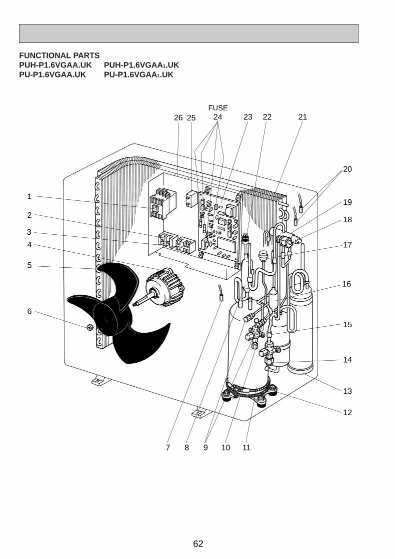
62
15
14
13
12
1
6
18
19
20
2126 2225 2324
7 8 9 10 11
2
4
5
17
16
3
FUSE
FUNCTIONAL PARTSPUH-P1.6VGAA.UK PUH-P1.6VGAA 1.UKPU-P1.6VGAA.UK PU-P1.6VGAA 1.UK
OC261-D--3.qxp 05.2.18 11:17 AM Page 62
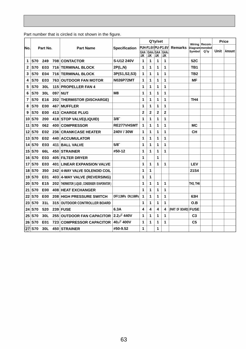
63
Part number that is circled is not shown in the figure.
Price
Part No. Part Name SpecificationNo.Wiring
DiagramSymbol
Recom-mended
Q,ty Unit Amount
Remarks
Q,ty/set
GAA.UK
GAA1.UK
1
2
3
4
5
6
7
8
9
10
11
12
13
14
15
16
17
18
19
20
21
22
23
24
25
26
27
1
1
1
1
1
1
1
1
2
1
1
1
1
1
1
1
1
1
1
1
1
1
1
4
1
1
1
1
1
1
1
1
1
1
1
2
1
1
1
1
1
1
1
1
1
1
1
1
1
4
1
1
GAA.UK
GAA1.UK
1
1
1
1
1
1
1
1
2
1
1
1
1
1
1
1
1
1
1
1
1
4
1
1
1
1
1
1
1
1
1
1
1
2
1
1
1
1
1
1
1
1
1
1
1
4
1
1
52C
TB1
TB2
MF
TH4
MC
CH
LEV
21S4
TH3, TH6
63H
O.B
FUSE
C3
C5
S70 249 708
S70 E03 716
S70 E04 716
S70 E03 763
S70 30L 115
S70 30L 097
S70 E16 202
S70 E00 467
S70 E00 413
S70 200 418
S70 062 400
S70 E02 236
S70 E02 440
S70 E03 411
S70 66L 450
S70 E03 405
S70 E03 401
S70 350 242
S70 E01 403
S70 E15 202
S70 E00 408
S70 E00 208
S70 31L 315
S70 520 239
S70 30L 255
S70 E01 723
S70 30L 450
CONTACTOR
TERMINAL BLOCK
TERMINAL BLOCK
OUTDOOR FAN MOTOR
PROPELLER FAN 4
NUT
THERMISTOR (DISCHARGE)
MUFFLER
CHARGE PLUG
STOP VALVE(LIQUID)
COMPRESSOR
CRANKCASE HEATER
ACCUMULATOR
BALL VALVE
STRAINER
FILTER DRYER
LINEAR EXPANSION VALVE
4-WAY VALVE SOLENOID COIL
4-WAY VALVE (REVERSING)
THERMISTOR ( LIQUID , CONDENSER / EVAPORATOR )
HEAT EXCHANGER
HIGH PRESSURE SWITCH
OUTDOOR CONTROLLER BOARD
FUSE
OUTDOOR FAN CAPACITOR
COMPRESSOR CAPACITOR
STRAINER
S-U12 240V
2P(L,N)
3P(S1,S2,S3)
N026P72MT
M8
3/8˝
RE277VHSMT
240V / 30W
5/8˝
#50-12
OFF:3.3MPa ON:2.6MPa
6.3A
2.2+ 440V
40+ 400V
#50-9.52
(PART OF BOARD)
PUH-P1.6V PU-P1.6V
OC261-D--3.qxp 05.2.18 11:17 AM Page 63

64
15
14
13
12
1
6
18
19
20
212225 2324
7 8 9 10 11
2
4
5
17
16
3
FUSE
FUNCTIONAL PARTSPUH-P1.6YGAA.UK PUH-P1.6YGAA 1.UKPU-P1.6YGAA.UK PU-P1.6YGAA 1.UK
OC261-D--3.qxp 05.2.18 11:17 AM Page 64
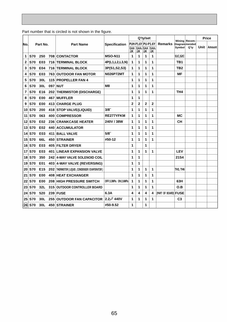
65
Part number that is circled is not shown in the figure.
Price
Part No. Part Name SpecificationNo.Wining
DiagramSymbol
Recom-mended
Q,ty Unit Amount
Remarks
Q,ty/set
GAA.UK
GAA1.UK
1
2
3
4
5
6
7
8
9
10
11
12
13
14
15
16
17
18
19
20
21
22
23
24
25
26
1
1
1
1
1
1
1
1
2
1
1
1
1
1
1
1
1
1
1
1
1
1
1
4
1
1
1
1
1
1
1
1
1
1
2
1
1
1
1
1
1
1
1
1
1
1
1
1
4
1
GAA.UK
GAA1.UK
1
1
1
1
1
1
1
2
1
1
1
1
1
1
1
1
1
1
1
1
4
1
1
1
1
1
1
1
1
1
2
1
1
1
1
1
1
1
1
1
1
1
4
1
51C,52C
TB1
TB2
MF
TH4
MC
CH
LEV
21S4
TH3, TH6
63H
O.B
FUSE
C3
S70 250 708
S70 E03 716
S70 E04 716
S70 E03 763
S70 30L 115
S70 30L 097
S70 E16 202
S70 E00 467
S70 E00 413
S70 200 418
S70 063 400
S70 E02 236
S70 E02 440
S70 E03 411
S70 66L 450
S70 E03 405
S70 E03 401
S70 350 242
S70 E01 403
S70 E15 202
S70 E00 408
S70 E00 208
S70 32L 315
S70 520 239
S70 30L 255
S70 30L 450
CONTACTOR
TERMINAL BLOCK
TERMINAL BLOCK
OUTDOOR FAN MOTOR
PROPELLER FAN 4
NUT
THERMISTOR (DISCHARGE)
MUFFLER
CHARGE PLUG
STOP VALVE(LIQUID)
COMPRESSOR
CRANKCASE HEATER
ACCUMULATOR
BALL VALVE
STRAINER
FILTER DRYER
LINEAR EXPANSION VALVE
4-WAY VALVE SOLENOID COIL
4-WAY VALVE (REVERSING)
THERMISTOR ( LIQUID , CONDENSER / EVAPORATOR )
HEAT EXCHANGER
HIGH PRESSURE SWITCH
OUTDOOR CONTROLLER BOARD
FUSE
OUTDOOR FAN CAPACITOR
STRAINER
PUH-P1.6Y PU-P1.6Y
MSO-N11
4P(L1,L2,L3,N)
3P(S1,S2,S3)
N026P72MT
M8
3/8˝
RE277YFKM
240V / 38W
5/8˝
#50-12
OFF:3.3MPa ON:2.6MPa
6.3A
2.2+ 440V
#50-9.52
(PART OF BOARD)
OC261-D--3.qxp 05.2.18 11:17 AM Page 65

66
18
17
15
14
13
12
1
5
7 8 9 10 11
6
19
21222326 2425
4
20
16
FUNCTIONAL PARTSPUH-P2VGAA.UK PUH-P2VGAA 1.UKPU-P2VGAA.UK PU-P2VGAA 1.UK
3
2
FUSE
OC261-D--3.qxp 05.2.18 11:17 AM Page 66
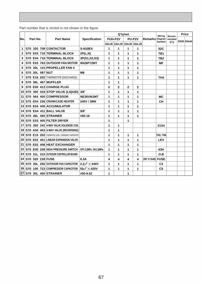
67
Part No. Part Name SpecificationNo.Wiring
DiagramSymbol
Recom-mended
Q,ty Unit Amount
Remarks
Q,ty/set
GAA.UK GAA1.UK GAA.UK GAA1.UK
S-N18EX
2P(L,N)
3P(S1,S2,S3)
N026P72MT
M8
3/8˝
NE36VMJMT
240V / 38W
5/8˝
#50-16
OFF:3.3MPa ON:2.6MPa
6.3A
2.2+ ✕ 440V
50+ ✕ 420V
#50-9.52
(PART OF BOARD)
1
2
3
4
5
6
7
8
9
10
11
12
13
14
15
16
17
18
19
20
21
22
23
24
25
26
27
1
1
1
1
1
1
1
1
2
1
1
1
1
1
1
1
1
1
1
1
1
1
1
4
1
1
1
1
1
1
1
1
1
1
1
2
1
1
1
1
1
1
1
1
1
1
1
1
1
4
1
1
1
1
1
1
1
1
1
2
1
1
1
1
1
1
1
1
1
1
1
1
4
1
1
1
1
1
1
1
1
1
1
2
1
1
1
1
1
1
1
1
1
1
1
4
1
1
52C
TB1
TB2
MF
TH4
MC
CH
21S4
TH3, TH6
LEV
63H
O.B
FUSE
C3
C5
S70 330 708
S70 E03 716
S70 E04 716
S70 E03 763
S70 30L 115
S70 30L 097
S70 E16 202
S70 36L 467
S70 E00 413
S70 300 418
S70 064 400
S70 E04 236
S70 E04 440
S70 E04 411
S70 36L 450
S70 E03 405
S70 350 242
S70 A00 403
S70 E15 202
S70 E02 401
S70 E02 408
S70 E00 208
S70 31L 315
S70 520 239
S70 30L 255
S70 100 723
S70 30L 450
CONTACTOR
TERMINAL BLOCK
TERMINAL BLOCK
OUTDOOR FAN MOTOR
PROPELLER FAN 4
NUT
THERMISTOR (DISCHARGE)
MUFFLER
CHARGE PLUG
STOP VALVE (LIQUID)
COMPRESSOR
CRANKCASE HEATER
ACCUMULATOR
BALL VALVE
STRAINER
FILTER DRYER
4-WAY VALVE SOLENOID COIL
4-WAY VALVE (REVERSING)
THERMISTOR( LIQUID , CONDENSER / EVAPORATOR )
LINEAR EXPANSION VALVE
HEAT EXCHANGER
HIGH PRESSURE SWITCH
OUTDOOR CONTROLLER BOARD
FUSE
OUTDOOR FAN CAPACITOR
COMPRESSOR CAPACITOR
STRAINER
PUH-P2V PU-P2V
Price
Part number that is circled is not shown in the figure.
OC261-D--3.qxp 05.2.18 11:17 AM Page 67

68
18
17
15
14
13
12
1
5
7 8 9 10 11
6
19
21222326 2425
4
20
16
FUNCTIONAL PARTSPUH-P2.5VGAA.UK PUH-P2.5VGAA 1.UKPU-P2.5VGAA.UK PU-P2.5VGAA 1.UK
3
2
FUSE
OC261-D--3.qxp 05.2.18 11:17 AM Page 68
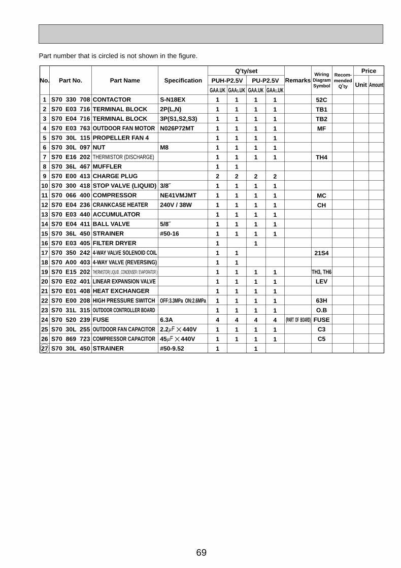
69
Part No. Part Name SpecificationNo.Wiring
DiagramSymbol
Recom-mended
Q,ty Unit Amount
Remarks
Q,ty/set
GAA.UK GAA1.UK GAA.UK GAA1.UK
S-N18EX
2P(L,N)
3P(S1,S2,S3)
N026P72MT
M8
3/8˝
NE41VMJMT
240V / 38W
5/8˝
#50-16
OFF:3.3MPa ON:2.6MPa
6.3A
2.2+ ✕ 440V
45+ ✕ 440V
#50-9.52
(PART OF BOARD)
1
2
3
4
5
6
7
8
9
10
11
12
13
14
15
16
17
18
19
20
21
22
23
24
25
26
27
1
1
1
1
1
1
1
1
2
1
1
1
1
1
1
1
1
1
1
1
1
1
1
4
1
1
1
1
1
1
1
1
1
1
1
2
1
1
1
1
1
1
1
1
1
1
1
1
1
4
1
1
1
1
1
1
1
1
1
2
1
1
1
1
1
1
1
1
1
1
1
1
4
1
1
1
1
1
1
1
1
1
1
2
1
1
1
1
1
1
1
1
1
1
1
4
1
1
52C
TB1
TB2
MF
TH4
MC
CH
21S4
TH3, TH6
LEV
63H
O.B
FUSE
C3
C5
S70 330 708
S70 E03 716
S70 E04 716
S70 E03 763
S70 30L 115
S70 30L 097
S70 E16 202
S70 36L 467
S70 E00 413
S70 300 418
S70 066 400
S70 E04 236
S70 E03 440
S70 E04 411
S70 36L 450
S70 E03 405
S70 350 242
S70 A00 403
S70 E15 202
S70 E02 401
S70 E01 408
S70 E00 208
S70 31L 315
S70 520 239
S70 30L 255
S70 869 723
S70 30L 450
CONTACTOR
TERMINAL BLOCK
TERMINAL BLOCK
OUTDOOR FAN MOTOR
PROPELLER FAN 4
NUT
THERMISTOR (DISCHARGE)
MUFFLER
CHARGE PLUG
STOP VALVE (LIQUID)
COMPRESSOR
CRANKCASE HEATER
ACCUMULATOR
BALL VALVE
STRAINER
FILTER DRYER
4-WAY VALVE SOLENOID COIL
4-WAY VALVE (REVERSING)
THERMISTOR( LIQUID , CONDENSER / EVAPORATOR )
LINEAR EXPANSION VALVE
HEAT EXCHANGER
HIGH PRESSURE SWITCH
OUTDOOR CONTROLLER BOARD
FUSE
OUTDOOR FAN CAPACITOR
COMPRESSOR CAPACITOR
STRAINER
PUH-P2.5V PU-P2.5V
Price
Part number that is circled is not shown in the figure.
OC261-D--3.qxp 05.2.18 11:17 AM Page 69
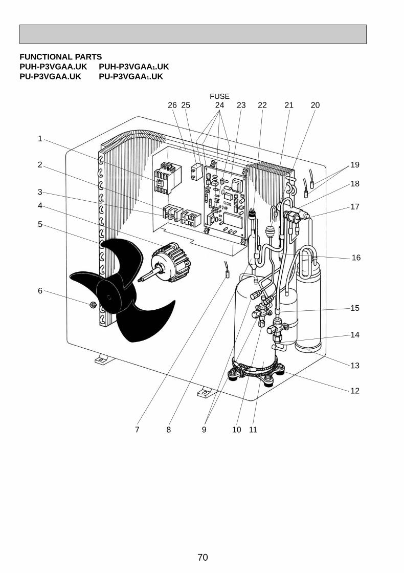
70
18
17
15
14
13
12
1
5
7 8 9 10 11
6
19
21222326 2425
4
20
16
FUNCTIONAL PARTSPUH-P3VGAA.UK PUH-P3VGAA 1.UKPU-P3VGAA.UK PU-P3VGAA 1.UK
3
2
FUSE
OC261-D--3.qxp 05.2.18 11:17 AM Page 70

71
Part No. Part Name SpecificationNo.Wiring
DiagramSymbol
Recom-mended
Q,ty Unit Amount
Remarks
Q,ty/set
GAA.UK GAA1.UK GAA.UK GAA1.UK
S-N18EX
2P(L,N)
3P(S1,S2,S3)
N026P72MT
M8
3/8˝
NE52VNJMT
240V / 38W
5/8˝
#50-16
OFF:3.3MPa ON:2.6MPa
6.3A
2.2+ ✕ 440V
60+ ✕ 450V
#50-9.52
(PART OF BOARD)
1
2
3
4
5
6
7
8
9
10
11
12
13
14
15
16
17
18
19
20
21
22
23
24
25
26
27
1
1
1
1
1
1
1
1
2
1
1
1
1
1
1
1
1
1
1
1
1
1
1
4
1
1
1
1
1
1
1
1
1
1
1
2
1
1
1
1
1
1
1
1
1
1
1
1
1
4
1
1
1
1
1
1
1
1
1
2
1
1
1
1
1
1
1
1
1
1
1
1
4
1
1
1
1
1
1
1
1
1
1
2
1
1
1
1
1
1
1
1
1
1
1
4
1
1
52C
TB1
TB2
MF
TH4
MC
CH
21S4
TH3, TH6
LEV
63H
O.B
FUSE
C3
C5
S70 330 708
S70 E03 716
S70 E04 716
S70 E03 763
S70 30L 115
S70 30L 097
S70 E16 202
S70 36L 467
S70 E00 413
S70 300 418
S70 068 400
S70 E04 236
S70 E03 440
S70 E04 411
S70 36L 450
S70 E03 405
S70 350 242
S70 A00 403
S70 E15 202
S70 E02 401
S70 E03 408
S70 E00 208
S70 31L 315
S70 520 239
S70 30L 255
S70 976 723
S70 30L 450
CONTACTOR
TERMINAL BLOCK
TERMINAL BLOCK
OUTDOOR FAN MOTOR
PROPELLER FAN 4
NUT
THERMISTOR (DISCHARGE)
MUFFLER
CHARGE PLUG
STOP VALVE (LIQUID)
COMPRESSOR
CRANKCASE HEATER
ACCUMULATOR
BALL VALVE
STRAINER
FILTER DRYER
4-WAY VALVE SOLENOID COIL
4-WAY VALVE (REVERSING)
THERMISTOR( LIQUID , CONDENSER / EVAPORATOR )
LINEAR EXPANSION VALVE
HEAT EXCHANGER
HIGH PRESSURE SWITCH
OUTDOOR CONTROLLER BOARD
FUSE
OUTDOOR FAN CAPACITOR
COMPRESSOR CAPACITOR
STRAINER
PUH-P3V PU-P3V
Price
Part number that is circled is not shown in the figure.
OC261-D--3.qxp 05.2.18 11:17 AM Page 71

72
18
17
15
14
13
12
1
2
3
5
7 8 9 10 11
6
19
2122232425
4
20
16
FUNCTIONAL PARTSPUH-P2YGAA.UK PUH-P2YGAA 1.UKPU-P2YGAA.UK PU-P2YGAA 1.UK
FUSE
OC261-D--3.qxp 05.2.18 11:17 AM Page 72
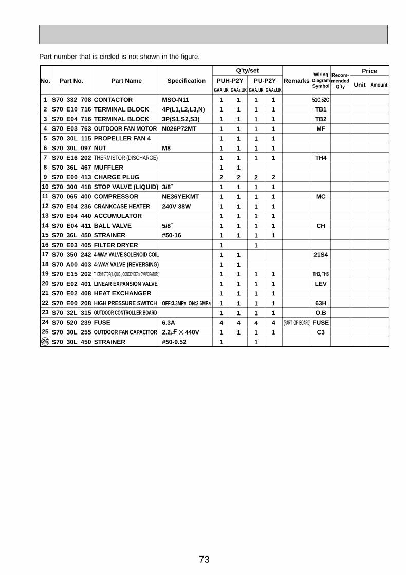
73
Part No. Part Name SpecificationNo.Wiring
DiagramSymbol
Recom-mended
Q,ty Unit Amount
Remarks
Q,ty/set
GAA.UK GAA1.UK GAA.UK GAA1.UK
MSO-N11
4P(L1,L2,L3,N)
3P(S1,S2,S3)
N026P72MT
M8
3/8˝
NE36YEKMT
240V 38W
5/8˝
#50-16
OFF:3.3MPa ON:2.6MPa
6.3A
2.2+ ✕ 440V
#50-9.52
(PART OF BOARD)
1
2
3
4
5
6
7
8
9
10
11
12
13
14
15
16
17
18
19
20
21
22
23
24
25
26
51C,52C
TB1
TB2
MF
TH4
MC
CH
21S4
TH3, TH6
LEV
63H
O.B
FUSE
C3
S70 332 708
S70 E10 716
S70 E04 716
S70 E03 763
S70 30L 115
S70 30L 097
S70 E16 202
S70 36L 467
S70 E00 413
S70 300 418
S70 065 400
S70 E04 236
S70 E04 440
S70 E04 411
S70 36L 450
S70 E03 405
S70 350 242
S70 A00 403
S70 E15 202
S70 E02 401
S70 E02 408
S70 E00 208
S70 32L 315
S70 520 239
S70 30L 255
S70 30L 450
CONTACTOR
TERMINAL BLOCK
TERMINAL BLOCK
OUTDOOR FAN MOTOR
PROPELLER FAN 4
NUT
THERMISTOR (DISCHARGE)
MUFFLER
CHARGE PLUG
STOP VALVE (LIQUID)
COMPRESSOR
CRANKCASE HEATER
ACCUMULATOR
BALL VALVE
STRAINER
FILTER DRYER
4-WAY VALVE SOLENOID COIL
4-WAY VALVE (REVERSING)
THERMISTOR( LIQUID , CONDENSER / EVAPORATOR )
LINEAR EXPANSION VALVE
HEAT EXCHANGER
HIGH PRESSURE SWITCH
OUTDOOR CONTROLLER BOARD
FUSE
OUTDOOR FAN CAPACITOR
STRAINER
PUH-P2Y PU-P2Y
Price
1
1
1
1
1
1
1
2
1
1
1
1
1
1
1
1
1
1
1
4
1
1
1
1
1
1
1
1
1
2
1
1
1
1
1
1
1
1
1
1
1
1
1
1
4
1
1
1
1
1
1
1
1
1
1
2
1
1
1
1
1
1
1
1
1
1
1
1
1
4
1
1
1
1
1
1
1
1
2
1
1
1
1
1
1
1
1
1
1
1
1
4
1
1
Part number that is circled is not shown in the figure.
OC261-D--3.qxp 05.2.18 11:17 AM Page 73
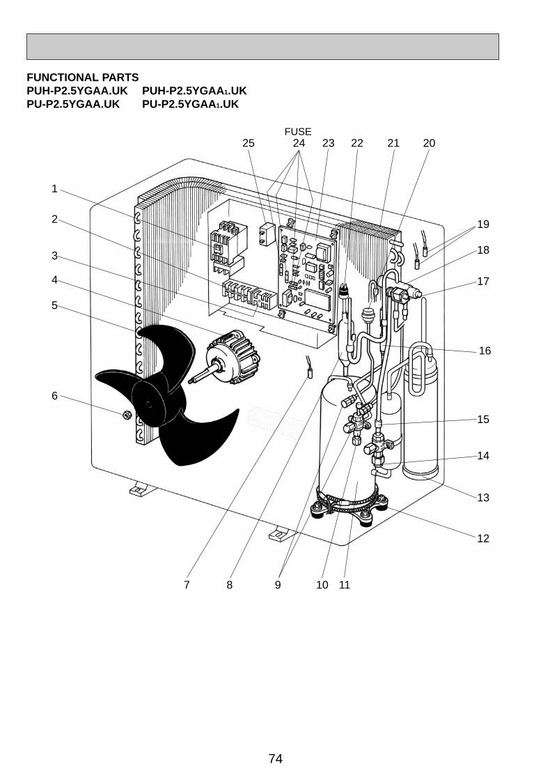
74
18
17
15
14
13
12
1
2
3
5
7 8 9 10 11
6
19
2122232425
4
20
16
FUNCTIONAL PARTSPUH-P2.5YGAA.UK PUH-P2.5YGAA 1.UKPU-P2.5YGAA.UK PU-P2.5YGAA 1.UK
FUSE
OC261-D--3.qxp 05.2.18 11:17 AM Page 74
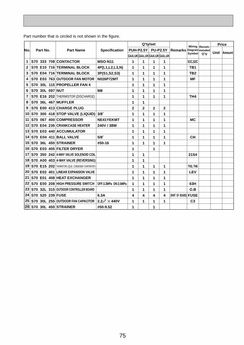
75
Part No. Part Name SpecificationNo.Wiring
DiagramSymbol
Recom-mended
Q,ty Unit Amount
Remarks
Q,ty/set
GAA.UK GAA1.UK GAA.UK GAA1.UK
MSO-N11
4P(L1,L2,L3,N)
3P(S1,S2,S3)
N026P72MT
M8
3/8˝
NE41YEKMT
240V / 38W
5/8˝
#50-16
OFF:3.3MPa ON:2.6MPa
6.3A
2.2+ ✕ 440V
#50-9.52
(PART OF BOARD)
1
2
3
4
5
6
7
8
9
10
11
12
13
14
15
16
17
18
19
20
21
22
23
24
25
26
51C,52C
TB1
TB2
MF
TH4
MC
CH
21S4
TH3, TH6
LEV
63H
O.B
FUSE
C3
S70 333 708
S70 E10 716
S70 E04 716
S70 E03 763
S70 30L 115
S70 30L 097
S70 E16 202
S70 36L 467
S70 E00 413
S70 300 418
S70 067 400
S70 E04 236
S70 E03 440
S70 E04 411
S70 36L 450
S70 E03 405
S70 350 242
S70 A00 403
S70 E15 202
S70 E02 401
S70 E01 408
S70 E00 208
S70 32L 315
S70 520 239
S70 30L 255
S70 30L 450
CONTACTOR
TERMINAL BLOCK
TERMINAL BLOCK
OUTDOOR FAN MOTOR
PROPELLER FAN 4
NUT
THERMISTOR (DISCHARGE)
MUFFLER
CHARGE PLUG
STOP VALVE (LIQUID)
COMPRESSOR
CRANKCASE HEATER
ACCUMULATOR
BALL VALVE
STRAINER
FILTER DRYER
4-WAY VALVE SOLENOID COIL
4-WAY VALVE (REVERSING)
THERMISTOR( LIQUID , CONDENSER / EVAPORATOR )
LINEAR EXPANSION VALVE
HEAT EXCHANGER
HIGH PRESSURE SWITCH
OUTDOOR CONTROLLER BOARD
FUSE
OUTDOOR FAN CAPACITOR
STRAINER
PUH-P2.5Y PU-P2.5Y
Price
1
1
1
1
1
1
1
2
1
1
1
1
1
1
1
1
1
1
1
4
1
1
1
1
1
1
1
1
1
2
1
1
1
1
1
1
1
1
1
1
1
1
1
1
4
1
1
1
1
1
1
1
1
1
1
2
1
1
1
1
1
1
1
1
1
1
1
1
1
4
1
1
1
1
1
1
1
1
2
1
1
1
1
1
1
1
1
1
1
1
1
4
1
1
Part number that is circled is not shown in the figure.
OC261-D--3.qxp 05.2.18 11:17 AM Page 75
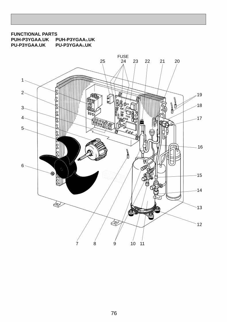
76
18
17
15
14
13
12
1
2
3
5
7 8 9 10 11
6
19
2122232425
4
20
16
FUNCTIONAL PARTSPUH-P3YGAA.UK PUH-P3YGAA 1.UKPU-P3YGAA.UK PU-P3YGAA 1.UK
FUSE
OC261-D--3.qxp 05.2.18 11:17 AM Page 76
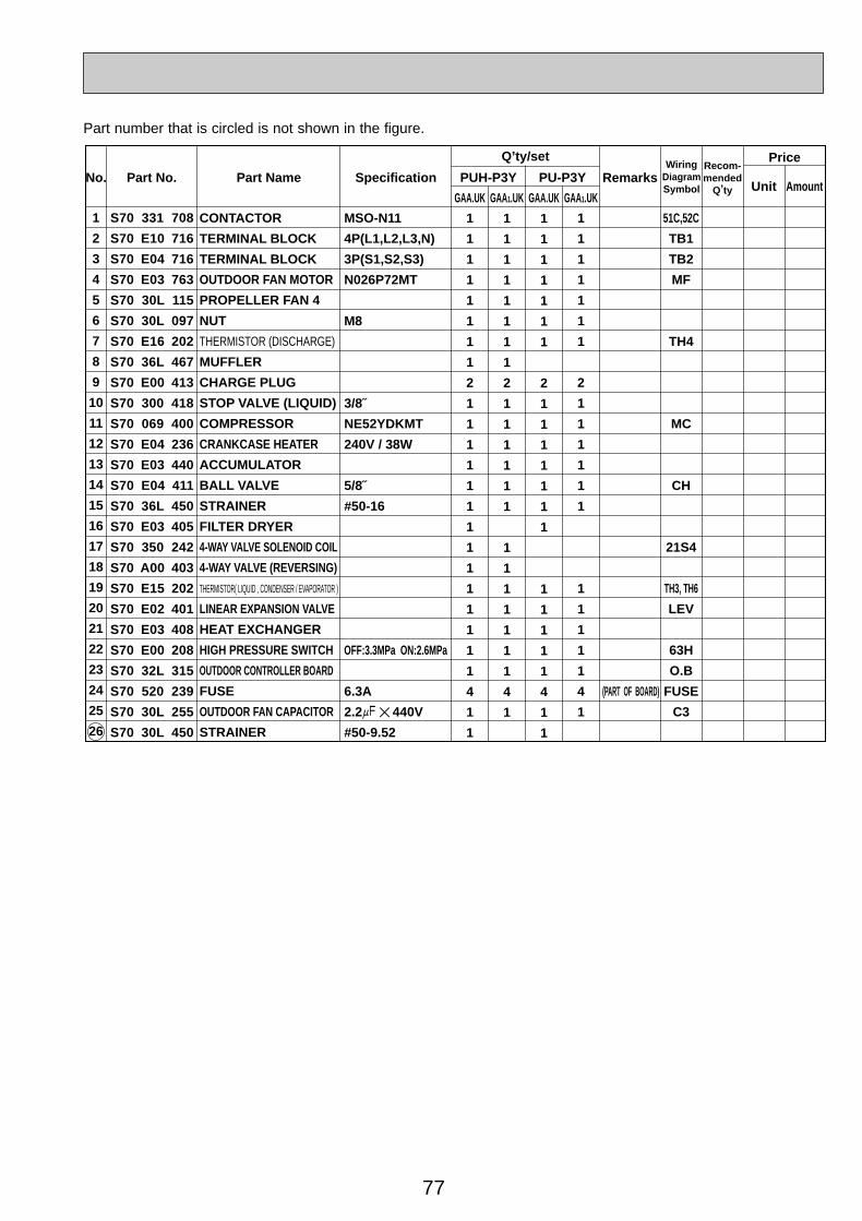
77
Part No. Part Name SpecificationNo.Wiring
DiagramSymbol
Recom-mended
Q,ty Unit Amount
Remarks
Q,ty/set
GAA.UK GAA1.UK GAA.UK GAA1.UK
MSO-N11
4P(L1,L2,L3,N)
3P(S1,S2,S3)
N026P72MT
M8
3/8˝
NE52YDKMT
240V / 38W
5/8˝
#50-16
OFF:3.3MPa ON:2.6MPa
6.3A
2.2+ ✕ 440V
#50-9.52
(PART OF BOARD)
1
2
3
4
5
6
7
8
9
10
11
12
13
14
15
16
17
18
19
20
21
22
23
24
25
26
51C,52C
TB1
TB2
MF
TH4
MC
CH
21S4
TH3, TH6
LEV
63H
O.B
FUSE
C3
S70 331 708
S70 E10 716
S70 E04 716
S70 E03 763
S70 30L 115
S70 30L 097
S70 E16 202
S70 36L 467
S70 E00 413
S70 300 418
S70 069 400
S70 E04 236
S70 E03 440
S70 E04 411
S70 36L 450
S70 E03 405
S70 350 242
S70 A00 403
S70 E15 202
S70 E02 401
S70 E03 408
S70 E00 208
S70 32L 315
S70 520 239
S70 30L 255
S70 30L 450
CONTACTOR
TERMINAL BLOCK
TERMINAL BLOCK
OUTDOOR FAN MOTOR
PROPELLER FAN 4
NUT
THERMISTOR (DISCHARGE)
MUFFLER
CHARGE PLUG
STOP VALVE (LIQUID)
COMPRESSOR
CRANKCASE HEATER
ACCUMULATOR
BALL VALVE
STRAINER
FILTER DRYER
4-WAY VALVE SOLENOID COIL
4-WAY VALVE (REVERSING)
THERMISTOR( LIQUID , CONDENSER / EVAPORATOR )
LINEAR EXPANSION VALVE
HEAT EXCHANGER
HIGH PRESSURE SWITCH
OUTDOOR CONTROLLER BOARD
FUSE
OUTDOOR FAN CAPACITOR
STRAINER
PUH-P3Y PU-P3Y
Price
1
1
1
1
1
1
1
2
1
1
1
1
1
1
1
1
1
1
1
4
1
1
1
1
1
1
1
1
1
2
1
1
1
1
1
1
1
1
1
1
1
1
1
1
4
1
1
1
1
1
1
1
1
1
1
2
1
1
1
1
1
1
1
1
1
1
1
1
1
4
1
1
1
1
1
1
1
1
2
1
1
1
1
1
1
1
1
1
1
1
1
4
1
1
Part number that is circled is not shown in the figure.
OC261-D--3.qxp 05.2.18 11:17 AM Page 77
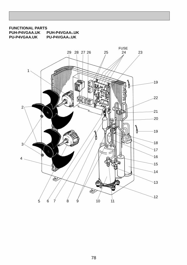
78
FUNCTIONAL PARTSPUH-P4VGAA.UK PUH-P4VGAA 1.UKPU-P4VGAA.UK PU-P4VGAA 1.UK
14
13
7 9 111086
4
15
18
19
22
221
12
29
1
27 2628 2425 23
3
20
5
16
17
19
FUSE
OC261-D--3.qxp 05.2.18 11:17 AM Page 78
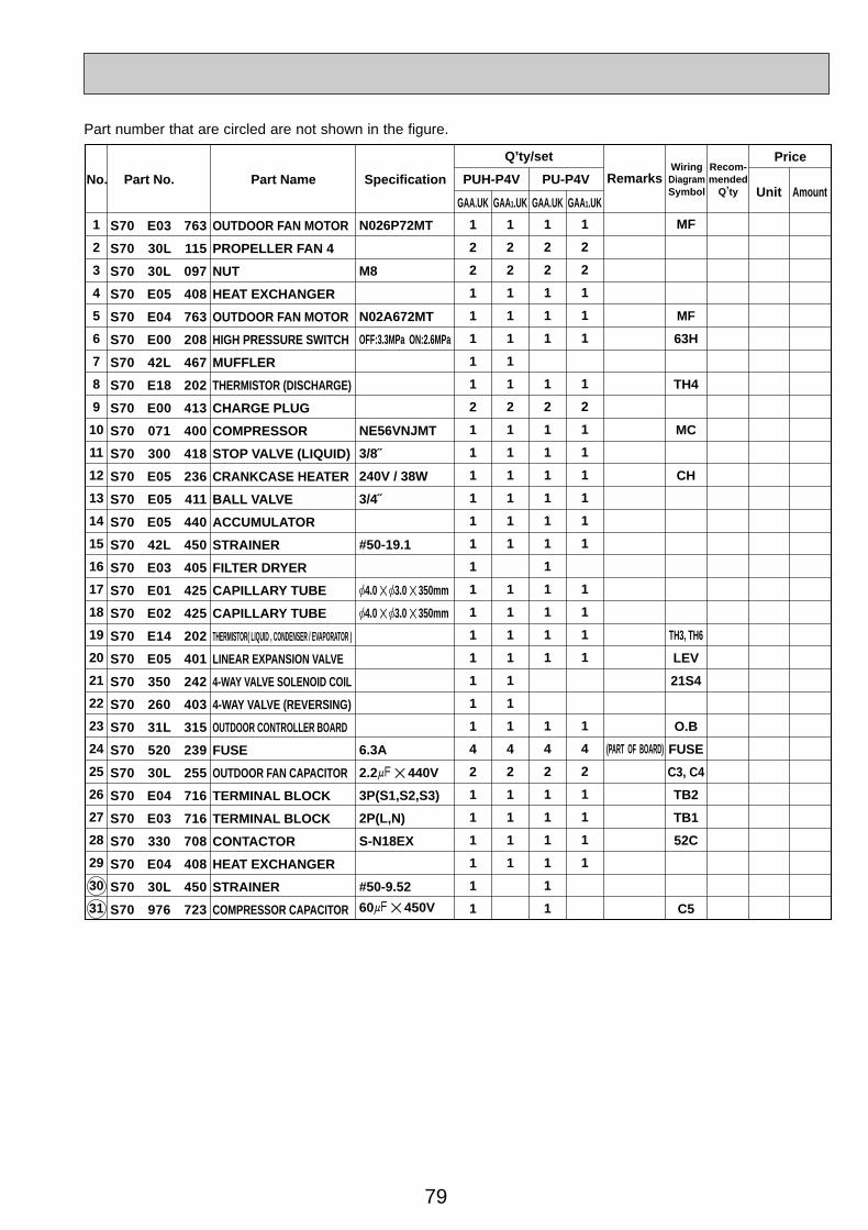
79
Part No. Part Name SpecificationNo.WiringDiagramSymbol
Recom-mended
Q,ty
Price
Unit Amount
N026P72MT
M8
N02A672MT
OFF:3.3MPa ON:2.6MPa
NE56VNJMT
3/8˝
240V / 38W
3/4˝
#50-19.1
[4.0 ✕ [3.0 ✕ 350mm
[4.0 ✕ [3.0 ✕ 350mm
6.3A
2.2+ ✕ 440V
3P(S1,S2,S3)
2P(L,N)
S-N18EX
#50-9.52
60+ ✕ 450V
RemarksPUH-P4V PU-P4V
Q,ty/set
1
2
3
4
5
6
7
8
9
10
11
12
13
14
15
16
17
18
19
20
21
22
23
24
25
26
27
28
29
30
31
1
2
2
1
1
1
1
1
2
1
1
1
1
1
1
1
1
1
1
1
1
1
1
4
2
1
1
1
1
1
1
1
2
2
1
1
1
1
1
2
1
1
1
1
1
1
1
1
1
1
1
1
1
4
2
1
1
1
1
1
2
2
1
1
1
1
2
1
1
1
1
1
1
1
1
1
1
1
1
4
2
1
1
1
1
1
1
1
2
2
1
1
1
1
2
1
1
1
1
1
1
1
1
1
1
1
4
2
1
1
1
1
MF
MF
63H
TH4
MC
CH
TH3, TH6
LEV
21S4
O.B
FUSE
C3, C4
TB2
TB1
52C
C5
S70 E03 763
S70 30L 115
S70 30L 097
S70 E05 408
S70 E04 763
S70 E00 208
S70 42L 467
S70 E18 202
S70 E00 413
S70 071 400
S70 300 418
S70 E05 236
S70 E05 411
S70 E05 440
S70 42L 450
S70 E03 405
S70 E01 425
S70 E02 425
S70 E14 202
S70 E05 401
S70 350 242
S70 260 403
S70 31L 315
S70 520 239
S70 30L 255
S70 E04 716
S70 E03 716
S70 330 708
S70 E04 408
S70 30L 450
S70 976 723
OUTDOOR FAN MOTOR
PROPELLER FAN 4
NUT
HEAT EXCHANGER
OUTDOOR FAN MOTOR
HIGH PRESSURE SWITCH
MUFFLER
THERMISTOR (DISCHARGE)
CHARGE PLUG
COMPRESSOR
STOP VALVE (LIQUID)
CRANKCASE HEATER
BALL VALVE
ACCUMULATOR
STRAINER
FILTER DRYER
CAPILLARY TUBE
CAPILLARY TUBE
THERMISTOR( LIQUID , CONDENSER / EVAPORATOR )
LINEAR EXPANSION VALVE
4-WAY VALVE SOLENOID COIL
4-WAY VALVE (REVERSING)
OUTDOOR CONTROLLER BOARD
FUSE
OUTDOOR FAN CAPACITOR
TERMINAL BLOCK
TERMINAL BLOCK
CONTACTOR
HEAT EXCHANGER
STRAINER
COMPRESSOR CAPACITOR
GAA.UK GAA1.UK GAA1.UKGAA.UK
(PART OF BOARD)
Part number that are circled are not shown in the figure.
OC261-D--3.qxp 05.2.18 11:17 AM Page 79

80
FUNCTIONAL PARTSPUH-P4YGAA.UK PUH-P4YGAA 1.UKPU-P4YGAA.UK PU-P4YGAA 1.UK
14
13
7 9 111086
4
15
18
19
22
221
12
29
1
27 2628 2425 23
3
20
5
16
17
19
FUSE
OC261-D--3.qxp 05.2.18 11:17 AM Page 80
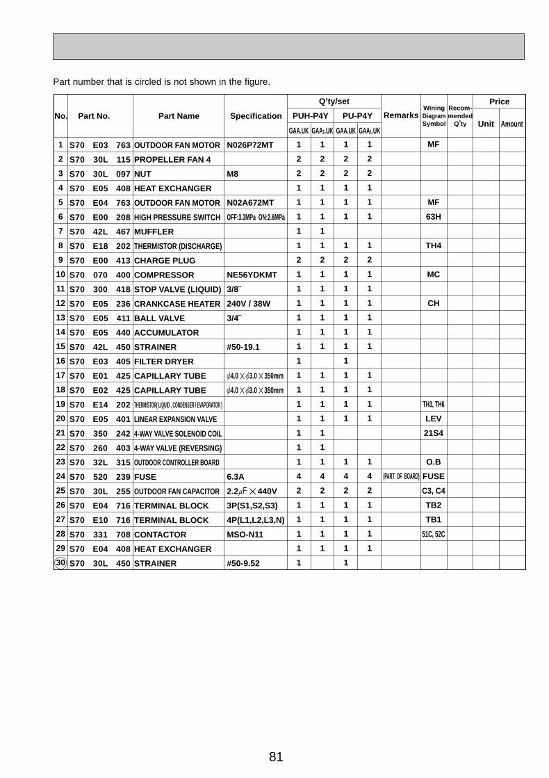
81
Part No. Part Name SpecificationNo.WiningDiagramSymbol
Recom-mended
Q,ty
Price
Unit Amount
N026P72MT
M8
N02A672MT
OFF:3.3MPa ON:2.6MPa
NE56YDKMT
3/8˝
240V / 38W
3/4˝
#50-19.1
[4.0 ✕ [3.0 ✕ 350mm
[4.0 ✕ [3.0 ✕ 350mm
6.3A
2.2+ ✕ 440V
3P(S1,S2,S3)
4P(L1,L2,L3,N)
MSO-N11
#50-9.52
RemarksPUH-P4Y PU-P4Y
Q,ty/set
1
2
3
4
5
6
7
8
9
10
11
12
13
14
15
16
17
18
19
20
21
22
23
24
25
26
27
28
29
30
1
2
2
1
1
1
1
1
2
1
1
1
1
1
1
1
1
1
1
1
1
1
1
4
2
1
1
1
1
1
1
2
2
1
1
1
1
1
2
1
1
1
1
1
1
1
1
1
1
1
1
1
4
2
1
1
1
1
1
2
2
1
1
1
1
2
1
1
1
1
1
1
1
1
1
1
1
1
4
2
1
1
1
1
1
1
2
2
1
1
1
1
2
1
1
1
1
1
1
1
1
1
1
1
4
2
1
1
1
1
MF
MF
63H
TH4
MC
CH
TH3, TH6
LEV
21S4
O.B
FUSE
C3, C4
TB2
TB1
51C, 52C
S70 E03 763
S70 30L 115
S70 30L 097
S70 E05 408
S70 E04 763
S70 E00 208
S70 42L 467
S70 E18 202
S70 E00 413
S70 070 400
S70 300 418
S70 E05 236
S70 E05 411
S70 E05 440
S70 42L 450
S70 E03 405
S70 E01 425
S70 E02 425
S70 E14 202
S70 E05 401
S70 350 242
S70 260 403
S70 32L 315
S70 520 239
S70 30L 255
S70 E04 716
S70 E10 716
S70 331 708
S70 E04 408
S70 30L 450
OUTDOOR FAN MOTOR
PROPELLER FAN 4
NUT
HEAT EXCHANGER
OUTDOOR FAN MOTOR
HIGH PRESSURE SWITCH
MUFFLER
THERMISTOR (DISCHARGE)
CHARGE PLUG
COMPRESSOR
STOP VALVE (LIQUID)
CRANKCASE HEATER
BALL VALVE
ACCUMULATOR
STRAINER
FILTER DRYER
CAPILLARY TUBE
CAPILLARY TUBE
THERMISTOR( LIQUID , CONDENSER / EVAPORATOR )
LINEAR EXPANSION VALVE
4-WAY VALVE SOLENOID COIL
4-WAY VALVE (REVERSING)
OUTDOOR CONTROLLER BOARD
FUSE
OUTDOOR FAN CAPACITOR
TERMINAL BLOCK
TERMINAL BLOCK
CONTACTOR
HEAT EXCHANGER
STRAINER
GAA.UK GAA1.UK GAA1.UKGAA.UK
(PART OF BOARD)
Part number that is circled is not shown in the figure.
OC261-D--3.qxp 05.2.18 11:17 AM Page 81

82
18
24
25
11
96 8
12
13
3
21
19
2
4
10
16
1
33 32 2931 30 28 27
FUNCTIONAL PARTSPUH-P5YGAA.UK PUH-P5YGAA 1.UKPU-P5YGAA.UK PU-P5YGAA 1.UK
15
17
26
22
14
75
12
23
20
FUSE
OC261-D--3.qxp 05.2.18 11:17 AM Page 82
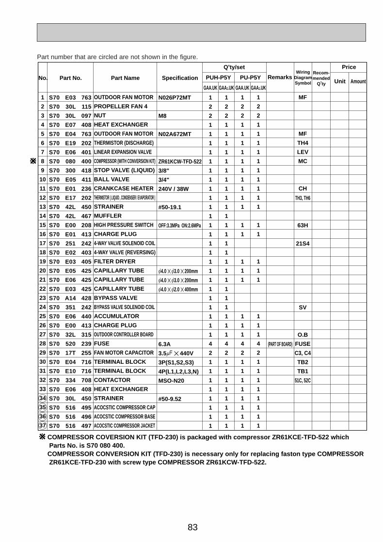
83
Part No. Part Name SpecificationNo.Wiring
DiagramSymbol
Recom-mended
Q,ty
Price
Unit AmountRemarks
Q,ty/set
PUH-P5Y PU-P5Y
GAA.UK GAA1.UK GAA.UK GAA1.UK
1
2
3
4
5
6
7
8
9
10
11
12
13
14
15
16
17
18
19
20
21
22
23
24
25
26
27
28
29
30
31
32
33
34
35
36
37
1
2
2
1
1
1
1
1
1
1
1
1
1
1
1
1
1
1
1
1
1
1
1
1
1
1
1
4
2
1
1
1
1
1
1
1
1
1
2
2
1
1
1
1
1
1
1
1
1
1
1
1
1
1
1
1
1
1
1
1
1
1
1
1
4
2
1
1
1
1
1
1
1
1
1
2
2
1
1
1
1
1
1
1
1
1
1
1
1
1
1
1
1
1
1
4
2
1
1
1
1
1
1
1
1
1
2
2
1
1
1
1
1
1
1
1
1
1
1
1
1
1
1
1
1
1
4
2
1
1
1
1
1
1
1
1
MF
MF
TH4
LEV
MC
CH
TH3, TH6
63H
21S4
SV
O.B
FUSE
C3, C4
TB2
TB1
51C, 52C
S70 E03 763
S70 30L 115
S70 30L 097
S70 E07 408
S70 E04 763
S70 E19 202
S70 E06 401
S70 080 400
S70 300 418
S70 E05 411
S70 E01 236
S70 E17 202
S70 42L 450
S70 42L 467
S70 E00 208
S70 E01 413
S70 251 242
S70 E02 403
S70 E03 405
S70 E05 425
S70 E06 425
S70 E03 425
S70 A14 428
S70 351 242
S70 E06 440
S70 E00 413
S70 32L 315
S70 520 239
S70 17T 255
S70 E04 716
S70 E10 716
S70 334 708
S70 E06 408
S70 30L 450
S70 516 495
S70 516 496
S70 516 497
OUTDOOR FAN MOTOR
PROPELLER FAN 4
NUT
HEAT EXCHANGER
OUTDOOR FAN MOTOR
THERMISTOR (DISCHARGE)
LINEAR EXPANSION VALVE
COMPRESSOR (WITH CONVERSION KIT)
STOP VALVE (LIQUID)
BALL VALVE
CRANKCASE HEATER
THERMISTOR ( LIQUID , CONDENSER / EVAPORATOR )
STRAINER
MUFFLER
HIGH PRESSURE SWITCH
CHARGE PLUG
4-WAY VALVE SOLENOID COIL
4-WAY VALVE (REVERSING)
FILTER DRYER
CAPILLARY TUBE
CAPILLARY TUBE
CAPILLARY TUBE
BYPASS VALVE
BYPASS VALVE SOLENOID COIL
ACCUMULATOR
CHARGE PLUG
OUTDOOR CONTROLLER BOARD
FUSE
FAN MOTOR CAPACITOR
TERMINAL BLOCK
TERMINAL BLOCK
CONTACTOR
HEAT EXCHANGER
STRAINER
ACOCSTIC COMPRESSOR CAP
ACOCSTIC COMPRESSOR BASE
ACOCSTIC COMPRESSOR JACKET
N026P72MT
M8
N02A672MT
ZR61KCW-TFD-522
3/8"
3/4"
240V / 38W
#50-19.1
OFF:3.3MPa ON:2.6MPa
[4.0 ✕ [3.0 ✕ 200mm
[4.0 ✕ [3.0 ✕ 200mm
[4.0 ✕ [2.0 ✕ 400mm
6.3A
3.5+ ✕ 440V
3P(S1,S2,S3)
4P(L1,L2,L3,N)
MSO-N20
#50-9.52
(PART OF BOARD)
W
COMPRESSOR COVERSION KIT (TFD-230) is packaged with compressor ZR61KCE-TFD-522 which Parts No. is S70 080 400.COMPRESSOR CONVERSION KIT (TFD-230) is necessary only for replacing faston type COMPRESSOR ZR61KCE-TFD-230 with screw type COMPRESSOR ZR61KCW-TFD-522.
W
Part number that are circled are not shown in the figure.
OC261-D--3.qxp 05.2.18 11:17 AM Page 83
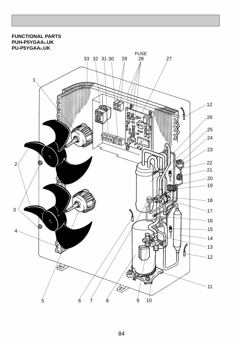
84
18
23
25
11
96 8
12
13
3
20
2
4
10
16
1
33 32 2931 30 28 27
FUNCTIONAL PARTSPUH-P5YGAA2.UKPU-P5YGAA2.UK
15
17
26
21
14
75
12
22
19
FUSE
24
OC261-D--3.qxp 05.2.18 11:17 AM Page 84
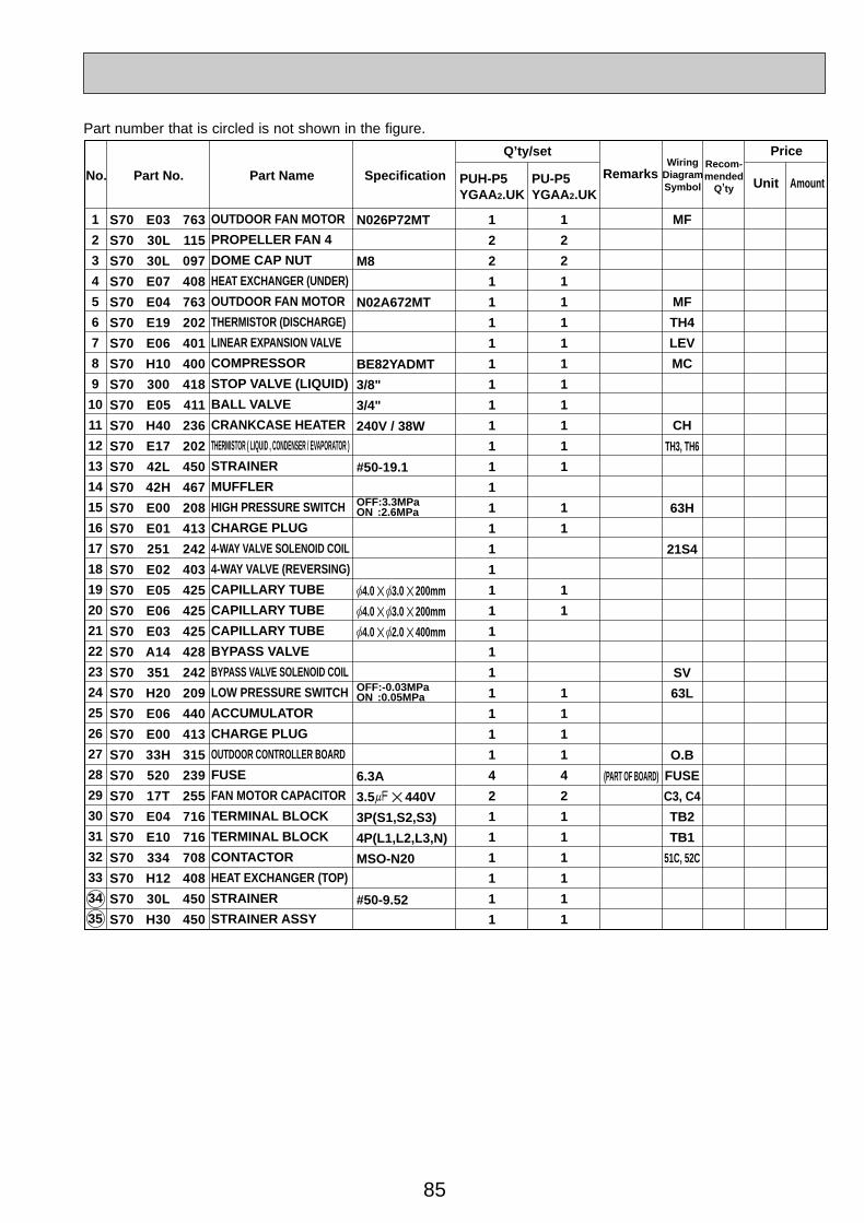
85
Part No. Part Name SpecificationNo.Wiring
DiagramSymbol
Recom-mended
Q,ty
Price
Unit AmountRemarks
Q,ty/set
PUH-P5YGAA2.UK
PU-P5YGAA2.UK
1
2
3
4
5
6
7
8
9
10
11
12
13
14
15
16
17
18
19
20
21
22
23
24
25
26
27
28
29
30
31
32
33
34
35
1
2
2
1
1
1
1
1
1
1
1
1
1
1
1
1
1
1
1
1
1
1
1
1
1
1
1
4
2
1
1
1
1
1
1
1
2
2
1
1
1
1
1
1
1
1
1
1
1
1
1
1
1
1
1
1
4
2
1
1
1
1
1
1
MF
MF
TH4
LEV
MC
CH
TH3, TH6
63H
21S4
SV
63L
O.B
FUSE
C3, C4
TB2
TB1
51C, 52C
S70 E03 763
S70 30L 115
S70 30L 097
S70 E07 408
S70 E04 763
S70 E19 202
S70 E06 401
S70 H10 400
S70 300 418
S70 E05 411
S70 H40 236
S70 E17 202
S70 42L 450
S70 42H 467
S70 E00 208
S70 E01 413
S70 251 242
S70 E02 403
S70 E05 425
S70 E06 425
S70 E03 425
S70 A14 428
S70 351 242
S70 H20 209
S70 E06 440
S70 E00 413
S70 33H 315
S70 520 239
S70 17T 255
S70 E04 716
S70 E10 716
S70 334 708
S70 H12 408
S70 30L 450
S70 H30 450
OUTDOOR FAN MOTOR
PROPELLER FAN 4
DOME CAP NUT
HEAT EXCHANGER (UNDER)
OUTDOOR FAN MOTOR
THERMISTOR (DISCHARGE)
LINEAR EXPANSION VALVE
COMPRESSOR
STOP VALVE (LIQUID)
BALL VALVE
CRANKCASE HEATER
THERMISTOR ( LIQUID , CONDENSER / EVAPORATOR )
STRAINER
MUFFLER
HIGH PRESSURE SWITCH
CHARGE PLUG
4-WAY VALVE SOLENOID COIL
4-WAY VALVE (REVERSING)
CAPILLARY TUBE
CAPILLARY TUBE
CAPILLARY TUBE
BYPASS VALVE
BYPASS VALVE SOLENOID COIL
LOW PRESSURE SWITCH
ACCUMULATOR
CHARGE PLUG
OUTDOOR CONTROLLER BOARD
FUSE
FAN MOTOR CAPACITOR
TERMINAL BLOCK
TERMINAL BLOCK
CONTACTOR
HEAT EXCHANGER (TOP)
STRAINER
STRAINER ASSY
N026P72MT
M8
N02A672MT
BE82YADMT
3/8"
3/4"
240V / 38W
#50-19.1
[4.0 ✕ [3.0 ✕ 200mm
[4.0 ✕ [3.0 ✕ 200mm
[4.0 ✕ [2.0 ✕ 400mm
6.3A
3.5+ ✕ 440V
3P(S1,S2,S3)
4P(L1,L2,L3,N)
MSO-N20
#50-9.52
(PART OF BOARD)
OFF:-0.03MPa ON :0.05MPa
OFF:3.3MPa ON :2.6MPa
Part number that is circled is not shown in the figure.
OC261-D--3.qxp 05.2.18 11:17 AM Page 85
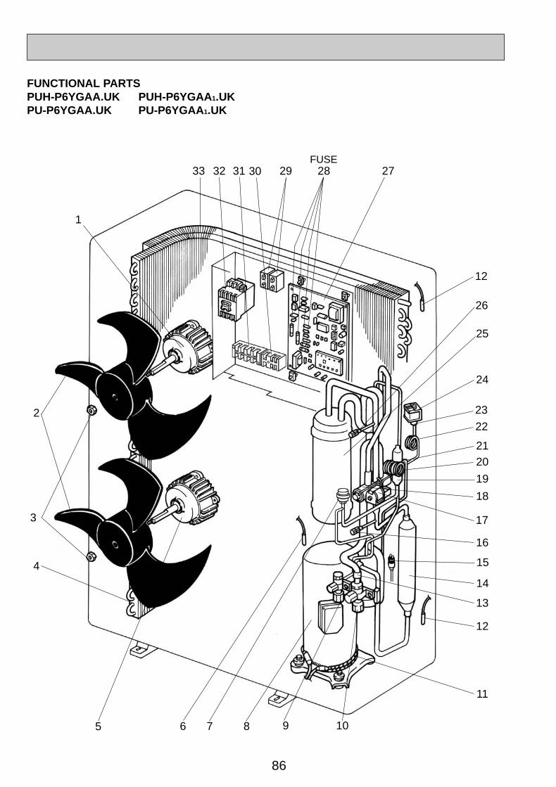
86
18
24
25
11
96 8
12
13
3
21
19
2
4
10
16
1
33 32 2931 30 28 27
FUNCTIONAL PARTSPUH-P6YGAA.UK PUH-P6YGAA 1.UKPU-P6YGAA.UK PU-P6YGAA 1.UK
15
17
26
22
14
75
12
23
20
FUSE
OC261-D--3.qxp 05.2.18 11:17 AM Page 86
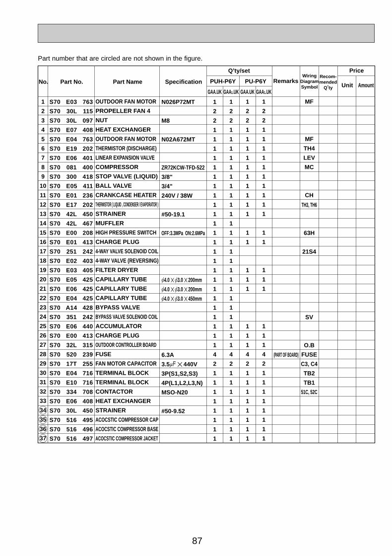
87
Part No. Part Name SpecificationNo.Wiring
DiagramSymbol
Recom-mended
Q,ty
Price
Unit AmountRemarks
Q,ty/set
PUH-P6Y PU-P6Y
GAA.UK GAA.UKGAA1.UK GAA1.UK
1
2
3
4
5
6
7
8
9
10
11
12
13
14
15
16
17
18
19
20
21
22
23
24
25
26
27
28
29
30
31
32
33
34
35
36
37
1
2
2
1
1
1
1
1
1
1
1
1
1
1
1
1
1
1
1
1
1
1
1
1
1
1
1
4
2
1
1
1
1
1
1
1
1
1
2
2
1
1
1
1
1
1
1
1
1
1
1
1
1
1
1
1
1
1
1
1
1
1
1
1
4
2
1
1
1
1
1
1
1
1
1
2
2
1
1
1
1
1
1
1
1
1
1
1
1
1
1
1
1
1
1
4
2
1
1
1
1
1
1
1
1
1
2
2
1
1
1
1
1
1
1
1
1
1
1
1
1
1
1
1
1
1
4
2
1
1
1
1
1
1
1
1
MF
MF
TH4
LEV
MC
CH
TH3, TH6
63H
21S4
SV
O.B
FUSE
C3, C4
TB2
TB1
51C, 52C
S70 E03 763
S70 30L 115
S70 30L 097
S70 E07 408
S70 E04 763
S70 E19 202
S70 E06 401
S70 081 400
S70 300 418
S70 E05 411
S70 E01 236
S70 E17 202
S70 42L 450
S70 42L 467
S70 E00 208
S70 E01 413
S70 251 242
S70 E02 403
S70 E03 405
S70 E05 425
S70 E06 425
S70 E04 425
S70 A14 428
S70 351 242
S70 E06 440
S70 E00 413
S70 32L 315
S70 520 239
S70 17T 255
S70 E04 716
S70 E10 716
S70 334 708
S70 E06 408
S70 30L 450
S70 516 495
S70 516 496
S70 516 497
OUTDOOR FAN MOTOR
PROPELLER FAN 4
NUT
HEAT EXCHANGER
OUTDOOR FAN MOTOR
THERMISTOR (DISCHARGE)
LINEAR EXPANSION VALVE
COMPRESSOR
STOP VALVE (LIQUID)
BALL VALVE
CRANKCASE HEATER
THERMISTOR ( LIQUID , CONDENSER / EVAPORATOR )
STRAINER
MUFFLER
HIGH PRESSURE SWITCH
CHARGE PLUG
4-WAY VALVE SOLENOID COIL
4-WAY VALVE (REVERSING)
FILTER DRYER
CAPILLARY TUBE
CAPILLARY TUBE
CAPILLARY TUBE
BYPASS VALVE
BYPASS VALVE SOLENOID COIL
ACCUMULATOR
CHARGE PLUG
OUTDOOR CONTROLLER BOARD
FUSE
FAN MOTOR CAPACITOR
TERMINAL BLOCK
TERMINAL BLOCK
CONTACTOR
HEAT EXCHANGER
STRAINER
ACOCSTIC COMPRESSOR CAP
ACOCSTIC COMPRESSOR BASE
ACOCSTIC COMPRESSOR JACKET
N026P72MT
M8
N02A672MT
ZR72KCW-TFD-522
3/8"
3/4"
240V / 38W
#50-19.1
OFF:3.3MPa ON:2.6MPa
[4.0 ✕ [3.0 ✕ 200mm
[4.0 ✕ [3.0 ✕ 200mm
[4.0 ✕ [3.0 ✕ 450mm
6.3A
3.5+ ✕ 440V
3P(S1,S2,S3)
4P(L1,L2,L3,N)
MSO-N20
#50-9.52
(PART OF BOARD)
Part number that are circled are not shown in the figure.
OC261-D--3.qxp 05.2.18 11:17 AM Page 87

88
18
23
25
11
96 8
12
13
3
20
2
4
10
16
1
33 32 2931 30 28 27
FUNCTIONAL PARTSPUH-P6YGAA2.UKPU-P6YGAA2.UK
15
17
26
21
14
75
12
22
19
FUSE
24
OC261-D--3.qxp 05.2.18 11:17 AM Page 88
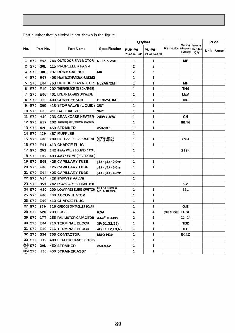
89
Part No. Part Name SpecificationNo.Wiring
DiagramSymbol
Recom-mended
Q,ty
Price
Unit AmountRemarks
Q,ty/set
1
2
3
4
5
6
7
8
9
10
11
12
13
14
15
16
17
18
19
20
21
22
23
24
25
26
27
28
29
30
31
32
33
34
35
1
2
2
1
1
1
1
1
1
1
1
1
1
1
1
1
1
1
1
1
1
1
1
1
1
1
1
4
2
1
1
1
1
1
1
1
2
2
1
1
1
1
1
1
1
1
1
1
1
1
1
1
1
1
1
1
4
2
1
1
1
1
1
1
MF
MF
TH4
LEV
MC
CH
TH3, TH6
63H
21S4
SV
63L
O.B
FUSE
C3, C4
TB2
TB1
51C, 52C
S70 E03 763
S70 30L 115
S70 30L 097
S70 E07 408
S70 E04 763
S70 E19 202
S70 E06 401
S70 H60 400
S70 300 418
S70 E05 411
S70 H40 236
S70 E17 202
S70 42L 450
S70 42H 467
S70 E00 208
S70 E01 413
S70 251 242
S70 E02 403
S70 E05 425
S70 E06 425
S70 E04 425
S70 A14 428
S70 351 242
S70 H20 209
S70 E06 440
S70 E00 413
S70 33H 315
S70 520 239
S70 17T 255
S70 E04 716
S70 E10 716
S70 334 708
S70 H12 408
S70 30L 450
S70 H30 450
OUTDOOR FAN MOTOR
PROPELLER FAN 4
DOME CAP NUT
HEAT EXCHANGER (UNDER)
OUTDOOR FAN MOTOR
THERMISTOR (DISCHARGE)
LINEAR EXPANSION VALVE
COMPRESSOR
STOP VALVE (LIQUID)
BALL VALVE
CRANKCASE HEATER
THERMISTOR ( LIQUID , CONDENSER / EVAPORATOR )
STRAINER
MUFFLER
HIGH PRESSURE SWITCH
CHARGE PLUG
4-WAY VALVE SOLENOID COIL
4-WAY VALVE (REVERSING)
CAPILLARY TUBE
CAPILLARY TUBE
CAPILLARY TUBE
BYPASS VALVE
BYPASS VALVE SOLENOID COIL
LOW PRESSURE SWITCH
ACCUMULATOR
CHARGE PLUG
OUTDOOR CONTROLLER BOARD
FUSE
FAN MOTOR CAPACITOR
TERMINAL BLOCK
TERMINAL BLOCK
CONTACTOR
HEAT EXCHANGER (TOP)
STRAINER
STRAINER ASSY
N026P72MT
M8
N02A672MT
BE96YADMT
3/8"
3/4"
240V / 38W
#50-19.1
[4.0 ✕ [3.0 ✕ 200mm
[4.0 ✕ [3.0 ✕ 200mm
[4.0 ✕ [3.0 ✕ 450mm
6.3A
3.5+ ✕ 440V
3P(S1,S2,S3)
4P(L1,L2,L3,N)
MSO-N20
#50-9.52
(PART OF BOARD)
PUH-P6YGAA2.UK
PU-P6YGAA2.UK
OFF:-0.03MPa ON :0.05MPa
OFF:3.3MPa ON :2.6MPa
Part number that is circled is not shown in the figure.
OC261-D--3.qxp 05.2.18 11:17 AM Page 89
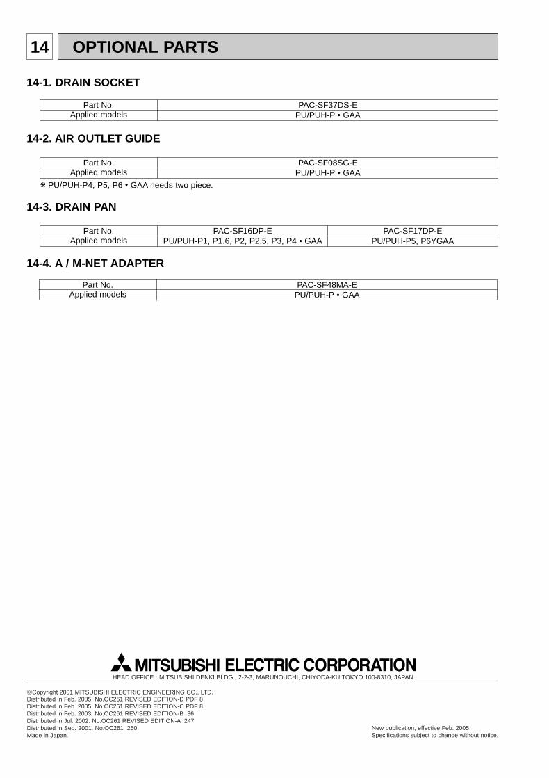
14 OPTIONAL PARTS
14-1. DRAIN SOCKET
Part No.Applied models
PAC-SF37DS-EPU/PUH-P • GAA
Part No.Applied models
PAC-SF08SG-EPU/PUH-P • GAA
14-2. AIR OUTLET GUIDE
Part No.Applied models
PAC-SF16DP-EPU/PUH-P1, P1.6, P2, P2.5, P3, P4 • GAA
14-3. DRAIN PAN
Part No.Applied models
PAC-SF48MA-EPU/PUH-P • GAA
14-4. A / M-NET ADAPTER
PAC-SF17DP-EPU/PUH-P5, P6YGAA
w PU/PUH-P4, P5, P6 • GAA needs two piece.
cCopyright 2001 MITSUBISHI ELECTRIC ENGINEERING CO., LTD.Distributed in Feb. 2005. No.OC261 REVISED EDITION-D PDF 8Distributed in Feb. 2005. No.OC261 REVISED EDITION-C PDF 8Distributed in Feb. 2003. No.OC261 REVISED EDITION-B 36Distributed in Jul. 2002. No.OC261 REVISED EDITION-A 247Distributed in Sep. 2001. No.OC261 250Made in Japan.
New publication, effective Feb. 2005Specifications subject to change without notice.
HEAD OFFICE : MITSUBISHI DENKI BLDG., 2-2-3, MARUNOUCHI, CHIYODA-KU TOKYO 100-8310, JAPAN
OC261-D--3.qxp 05.2.18 11:17 AM Page 90