technical specification of cables for … office/gen_gp_5253a_… · technical specification of...
TRANSCRIPT
SCHEDULE-A2
CEG/GP-2/5253A
TECHNICAL SPECIFICATION
OF CABLES
FOR POWER STATIONS
Installed

I N D E X
CLAUSE NO. TITLE Special Instruction to Bidder Qualifying Requirement of Bidder
SCHEDULE-B Technical specification for Control and L.T./H.T. Power Cables
1.0 Scope 2.0 Standards 3.0 Climatic Conditions 4.0 General Technical/Principal Parameters 5.0 Physical Constants of Materials 6.0 Physical Constants for Galvanized Steel Wires 7.0 Freedom from Defects 8.0 Wire Sizes 9.0 Joints in Wires
10.0 Stranding 11.0 Standard Length 12.0 Operation 13.0 Tests 14.0 Type Tests 15.0 Acceptance Tests 16.0 Routine Tests 17.0 Test During Manufacture 18.0 Testing Charges 19.0 Additional Charges 20.0 Sample Batch for Type Testing 21.0 Test Reports 22.0 Test Facilities 23.0 Inspection 24.0 Quality Assurance Plan 25.0 Documentation 26.0 Packaging and Forwarding 27.0 Marking 28.0 Quantity and Delivery Requirement 29.0 Drawing 30.0 Deviations
ANNEXURE-I System Particulars SCHEDULE-B7 GTP for HT Cable SCHEDULE-C7 GTP for HT Cable - to be filled by bidder
(This document is meant for exclusive purpose of bidding against this
specification and shall not transfer, reproduced or otherwise used for purposes other than that for which it is specifically issued.)

SPECIAL INSTRUCTIONS TO BIDDER Please read following instructions carefully before submitting your bid: 1. All the drawings, i.e. elevation, side view, plan, cross sectional view etc., in
AutoCAD format and manuals in PDF format, for offered item shall be submitted. Also the hard copies as per specification shall be submitted.
2. The bidder shall submit Quality Assurance Plan with the technical bid. 3. The bidder shall have to submit all the required type test reports for the offered
item. Bid without type tests will not be considered for evaluation. 4. The bidder must fill up all the points of GTP for offered item/s. Instead of
indicating “refer drawing, or as per IS/IEC”, the exact value/s must be filled in. 5. All the points other than GTP, which are asked to confirm in technical
specifications must be submitted separately with the bid. 6. The bidder is required to impart training in view of manufacture, assembly,
erection, operation and maintenance for offered item, at his works, to the person/s identified by GSECL, in the event of an order, free of cost. The cost of logistics will be bear by GSECL.
7. Please note that the evaluation will be carried out on the strength of content of bid only. No further correspondence will be made.
8. The bidder shall bring out all the technical deviation/s only at the specified
annexure.

QUALIFYING REQUIREMENT FOR BIDDER Bidder to satisfy all the following requirements- 1. The Bidders should be original manufacturer of the quoted size of the cables
and shall have all the facilities to manufacture these sizes and higher sizes of control and / or power cables as the case may be. Traders are not eligible for participating in this Tender.
2. The Bidders have to submit proof of the satisfactory completion of order for supply of quoted sizes of the cables for the quantity not less than 300 Kms during last five years of total of all the sizes of control cables from utilities like State Electricity Corporations, NTPC, PGCIL. Any Technical offer without this certificate will be out rightly rejected. The proof means the Purchaser’s certificate of completing the supply within the stipulated time limit for the ordered quantity. However the total quantity supplied shall not be less than the one stated above (i.e. 300 Kms).
The details are to be submitted in following format: Sr. No
ITEMS SUPP- LIED TO
ORDER REFEREN CE No. & DATE
ITEMS QTY ORDER FULLY EXECUTED. YES/NO
STATUS, IF ORDER UNDER EXECUTION
REMARK
3. The cables offered must bear ISI mark. The Bidder shall invariably submit the attested copy of ISI certificate. Any cables without this mark will be out rightly rejected. The cables will be accepted only from the works, name and address of which is indicated in the offer.
4. All the bids shall comprise the copy of type test reports, of any of the quoted size, which shall not be later than five years from the date of opening of the Tender. However GSECL reserves the right to ask any or all the suppliers to carry out the Type Test at the Government Approved Testing Laboratory on the ordered size/s. The GSECL reserves the right to indicate the name of the NABL accredited Testing Lab at his own discretion and the Supplier will have to carry out the Type Tests in the designated laboratory at his own cost.
5. The quantity of each size offered shall be indicated clearly in the Technical Bid. The Bid will be out rightly rejected if this clause is not found clear.
6. This Specification shall be signed page to page without any addition / alteration and shall be submitted with the Technical Bid. Any offer without this will be out rightly rejected.

SCHEDULE – B
TECHNICAL SPECIFICATION FOR CONTROL AND L.T. /H.T. POWER CABLES 1.0 SCOPE:
1.1 This specification provides for design, manufacture, testing, inspection,
packing and dispatch to destination of Copper Cored Control Cables and Aluminium cored HT / LT Power Cables, specified herein for their satisfactory operation in various Power stations of the State. Preparation of Drum drawings and getting it approved from C.E.-GSECL, Corporate Office, Vadodara.
1.2 These cables are to be used as control signal carrying cables or power carrying cables, as the case may be, in various Power stations of the Gujarat State situated in various areas having varying atmospheric conditions, for voltage ratings up to 400KV, from various equipments situated in Plant area, Control rooms, switchyard etc.
1.3 These cables are generally used under ground either in the cable trenches with no. of layers as per requirement covered with the cement covers or in the pipes installed under ground and then pits filled with the soil.
2.0 STANDARDS: 2.1 The Control, Power, Telephone and Trailing cables shall conform to the
following Indian / International Standards, which shall mean latest revisions, amendments / changes adopted and / or published as on the date of opening of the Tender.
Sr. No. Indian Standards Title
1 IS : 1554 For Cables up to working voltage 1100 V 2 IS : 7098 For XLPE Cables 3 IS : 5831 For Insulation Sheath 4 IS : 8130 For Copper And Aluminium Conductor 5 IS : 10418 For Wooden Drums 6 IS : 3975 For Armouring 7 IS : 3961 For Current Rating 8 IS : 9968 For Trailing Cables 9 IEC :189 / BS : 5308 For Instrument Cables 9 ITD: GR/CUG-01/03,
Aug-2003. For Telephone Cable
10 IEC-754, 332, ASTM D-2863, 2543
For FRLS Properties
2.2 Over and above, any other standards which are relevant may be quoted
by the bidder. However, in an event where the supplier offers Control and / or power cables conforming to standards other than the above, then the salient points of comparison between the standards adopted and the standards quoted herein shall be detailed in relevant schedule with an authenticated English version of such standards referred to.

GSECL also reserves right to ask any supplier to supply the control / power cables related to any other IS or International Standards which may be found to give better quality and performance of the cables.
3.0 CLIMATIC CONDITIONS: 3.1 The cables to be supplied under these Specifications are to be used in
various Power Stations of the Gujarat State, located at different locations having varying atmospheric and climatic conditions and are suppose to operate satisfactorily under any conditions.
3.2 However the General conditions are given as under:
1 Location In the State of Gujarat as per Annexure-I
2 Maximum Ambient Air Temperature -(C) 50 3 Minimum Ambient Air Temperature -(C) 0 4 Average daily ambient Air Temperature -(C) 35 5 Maximum relative humidity – (%) 95 6 Average rainfall per annum -(mm) 1150 7 Maximum altitude above mean sea level -
(mtr) 1000
8 Ceraunic level i.e. Average number of Thunder storm -(Days/annum)
15
9 Maximum wind pressure -(KG/m2) 200 10 Seismic level i.e. Earthquake Acceleration
a) Horizontal Seismic Co-efficient (acceleration) – g (Equivalent to zone – 5)
b) Vertical Seismic Co-efficient (acceleration) – g (Equivalent to zone – 5)
(a) 0.3 (b)0.34
11 Terrain Hot, Humid, Tropical, Highly Polluted, Conductive, Corrosive, Prone to Fungus Growth etc
4.0 GENERAL TECHNICAL / PRINCIPAL PARAMETERS:(SCHEDULE: B1-TO-B13): 4.1 CONTROL / LT CABLES: (1) The control cables shall be round copper conductor (of required size) with
PVC insulation, armouring and sheath, color coded as per relevant standards or as specified / instructed by the GSECL.
(2) The LT Power cables shall be of aluminium conductor (of required size) PVC insulated, armouring and PVC sheathed, colour coded as per relevant standards or as specified / instructed by the GSECL.

(3) The control cables shall be rated for minimum 1100 V and LT Power cables for minimum 6600 V, however Bidder may quote for higher voltage ratings, which shall be clearly brought out in the Technical Bid.
(4) All the cables quoted / supplied shall bear ISI mark. (5) The insulation of each core and outer and inner sheath, shall comply with
the relevant IS / this Specification, whichever is stringent, for control and / or power cables.
(6) All the armouring shall be strip / round wire type, hot dip galvanized. The armouring and galvanizing shall comply with relevant standards and or this Specification shall also bear ISI mark.
(7) The copper conductor used shall be electrolytic grade annealed and shall be made of minimum 99.5% pure copper, thus the total impurities shall not exceed 0.5%. The Aluminium conductor shall be of EC Grade 99.5% pure aluminium and thus the total impurities in this case also shall not exceed 0.5%. Both the copper and aluminium shall possess ISI mark.
(8) If the conductor is a bought out item or manufactured by the supplier, the proof to satisfy the above conditions shall be produced.
(9) Current Rating: The indicative values of continuous current carrying capacities at Maximum conductor temperature of 70º C (for design purpose by field) of the various sizes of the cables are given in GTP. Short circuit ratings of various sizes cable calculated for duration of one second at maximum temperature of 160º C, are given in GTP.
(10) The cables shall be suitable for being installed directly in the ground, in the pipes or in the cable trays/trenches. The cables shall therefore be suitable for satisfactory operation under the tropical climatic conditions listed in the relevant clause. The applicable design particular of the cables to be used in the Power Stations is furnished in Annexure - I. "System Particulars".
4.2 HT CABLE: (1) 11 KV (E) Grade XLPE, 3-Core, power cable shall be of high conductivity,
stranded compacted, H.D. aluminum circular shaped conductor with XLPE (Cross Linked Poly Ethylene) Dry/Gas cured insulation provided with shielding of extruded semi-conducting materials over conductor and XLPE insulation. Each insulated core shall have copper tape screen, laid together and provided with common covering of PVC Inner Sheath (Extruded). Overall galvanized steel strip armour and PVC outer sheath shall be provided. The specification for manufacture of cable shall be conforming to IS: 7098 (Part-II) 1985 (latest edition) for 11KV (E), 3-phase, 50 Hz, Earthed systems.
(2) Outer sheath shall be designed to afford high degree of mechanical protection and shall also be heat, oil, chemical and weather resistant, Common acid, alkalis and sealing solution shall not have adverse effect on material of PVC sheath.
(3) The cable conductor shall be made from high conductivity stranded High Density aluminum to form compacted circular shaped conductor having resistance within limits specified in IS: 8130/1984 and any latest amendment to it.

(4) The conductor having semi-conducing screen shall ensure perfectly smooth profile and avoid concentration of stress. The conductor screen shall be extruded in the same operation as the insulation. The semi-conducting polymer shall be cross linked.
(5) Cable Parameters:
1 Voltage grade (Uo / U)- KV 6.35 / 11 2 Cores (Nos) 3 3 Nominal system voltage -KV 11 4 Highest system voltage -KV 12 5 System frequency- Hz 50 6 Variation in frequency -% ± 3 7 Maximum allowable temp. of conductor during
continuous normal operation at rated full load current - ºC 90 º C
8 Maximum allowable temp. under short circuit condition-ºC 250 º C 9 1.2/50 microsecond lightning impulse withstands voltage
wave value - KVp 75
10 5 Min, Power frequency withstand voltage -KV rms 17 11 System earthling Effectively
earthed. (6) The XLPE insulation shall be suitable for 11 / 22 kV system voltage and
should be manufactured with Dry / Gas curing process. The bidder shall submit the description of dry / gas curing process, with the clear inclusion of equipments / parameters involved. The manufacturing process shall ensure that the insulation shall be free of voids. The insulation shall withstand mechanical and thermal stress under steady state and transient operating conditions. The extrusion method should give very smooth interface between semi-conducting screen and insulation. The insulation of the cable shall be of high standard quality generally conforming to IS: 7098 (Part – II) – 1985 and any latest amendment to it.
(7) Insulation shield: Non-metallic semi-conducting shield shall be provided over the insulation to confine electrical field to the insulation. The insulation shield shall be extruded in the same operation as the conductor shield and the insulation by suitable extrusion process. The XLPE insulation shield shall be of tended type. The copper metallic overlapped tape shield shall be provided.
(8) Filler and Inner-Sheath: The sheath shall be suitable to withstand the site conditions and the desired temperature. It shall be of adequate thickness, consistent quality and free from all defects. The PVC sheath shall be extruded. The material of fillers and inner-sheath shall be compatible with the temperature ratings of the cable and shall have no deterious effect on any other component of the cable. Central PVC filler shall also, be provided with other peripheral PVC fillers to have proper circular section.
(9) Outer-Sheath: Extruded type ST-2 PVC outer-sheath, conforming to IS: 5831- (1984) (latest edition) over armouring with suitable additives (to prevent attack by rodents and termites), shall be provided.
(10) Armour: Armoring of galvanized steel strip shall be provided. The dimensions of steel strips shall be as per latest edition of IS: 3975 – 1979.
(11) Cable shall be suitable for lying in covered trenches and / or buried under-ground in outdoor.
(12) Current Rating: The indicative values of continuous current carrying capacities at Maximum conductor temperature of 90º C (for design purpose by field) of the various sizes of the cables are given in GTP. Short circuit ratings of various sizes cable calculated for duration of one second at maximum temperature of 250º C, are given in GTP.
(13) The cables shall be suitable for being installed directly in the ground, in the pipes or in the cable trays/trenches. The cables shall therefore be suitable for satisfactory operation under the tropical climatic conditions listed in the relevant clause. The applicable design particular of the cables to be used in the Power Stations is furnished in Annexure - II. "System Particulars".
4.3 TELEPHONE CABLE:
Telephone Cable with annealed Copper conductor polyethylene insulated core twisted into pair laid up jelly filled cores wrapped with poly Aluminum Laminated moisture berried polyphone sheathed double steel tape armored overall black polyphone jacketed cable confirm to ITD Specification NO. GR / CUG -01 / 03, Aug 2003.
5.0 PHYSICAL CONSTANTS OF MATERIALS: 5.1 PHYSICAL CONSTANTS FOR COPPER / ALUMINIUM CONDUCTORS: 5.1.1 Resistivity: The volume resistivity of copper / aluminium depends upon its purity and its
physical condition. However as per the specified value of purity in this specification, the maximum value permitted is 0.01724 Ω-mm2/meter for copper and 0.28264 Ω-mm2/meter at 20 Deg. C, for aluminium. These values shall be used for calculation of the maximum permissible value of resistance. This value may be checked from the measured value of the resistance.
5.1.2 Density: At a temperature of 20C the minimum density of electrolytic grade
annealed copper shall be 8.89 and that of hard drawn aluminum shall be 2.703 Gm/CuCm.
5.2 Constant-Mass Temperature Co-efficient of Resistance: 5.2.1 At a temperature of 20C the constant-mass temperature co-efficient of
resistance of copper and hard drawn aluminum measured between two potential points rigidly fixed to the wire, the metal being allowed to expand freely, has been taken as 0.0039 and 0.004 per degree Celsius respectively for copper and aluminum.
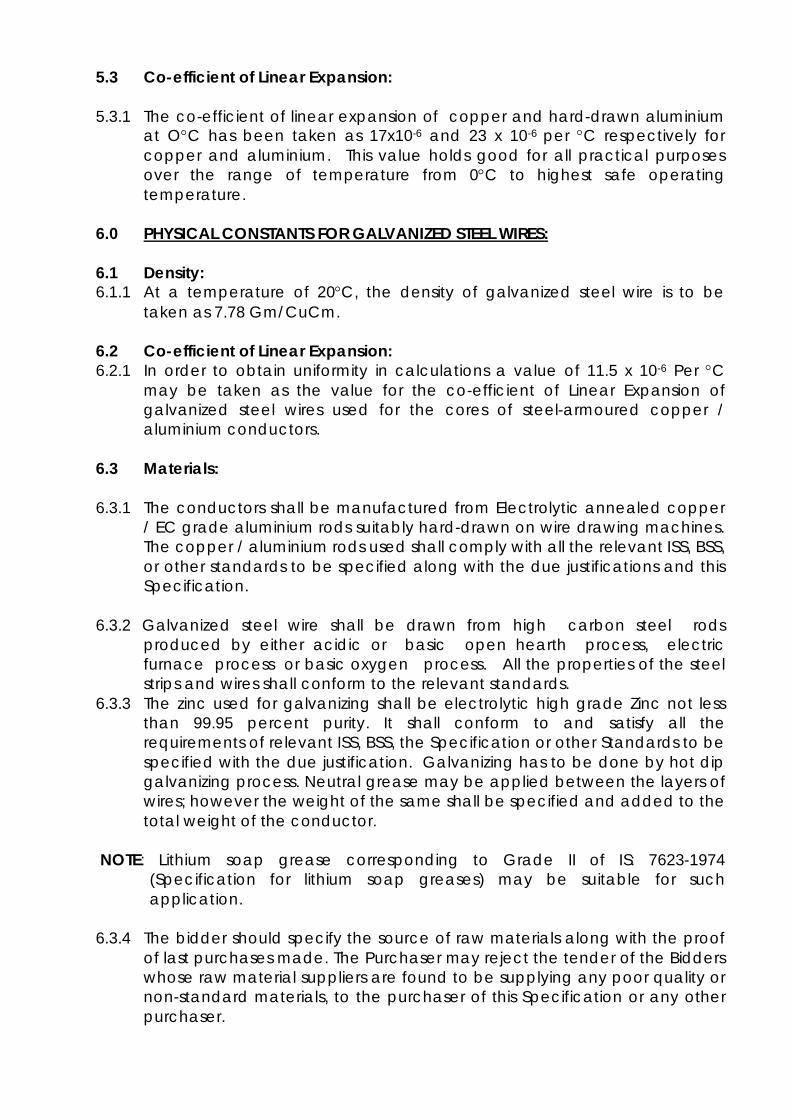
5.3 Co-efficient of Linear Expansion: 5.3.1 The co-efficient of linear expansion of copper and hard-drawn aluminium
at OC has been taken as 17x10-6 and 23 x 10-6 per C respectively for copper and aluminium. This value holds good for all practical purposes over the range of temperature from 0C to highest safe operating temperature.
6.0 PHYSICAL CONSTANTS FOR GALVANIZED STEEL WIRES: 6.1 Density: 6.1.1 At a temperature of 20C, the density of galvanized steel wire is to be
taken as 7.78 Gm/CuCm. 6.2 Co-efficient of Linear Expansion: 6.2.1 In order to obtain uniformity in calculations a value of 11.5 x 10⁻⁶ Per C
may be taken as the value for the co-efficient of Linear Expansion of galvanized steel wires used for the cores of steel-armoured copper / aluminium conductors.
6.3 Materials: 6.3.1 The conductors shall be manufactured from Electrolytic annealed copper
/ EC grade aluminium rods suitably hard-drawn on wire drawing machines. The copper / aluminium rods used shall comply with all the relevant ISS, BSS, or other standards to be specified along with the due justifications and this Specification.
6.3.2 Galvanized steel wire shall be drawn from high carbon steel rods
produced by either acidic or basic open hearth process, electric furnace process or basic oxygen process. All the properties of the steel strips and wires shall conform to the relevant standards.
6.3.3 The zinc used for galvanizing shall be electrolytic high grade Zinc not less than 99.95 percent purity. It shall conform to and satisfy all the requirements of relevant ISS, BSS, the Specification or other Standards to be specified with the due justification. Galvanizing has to be done by hot dip galvanizing process. Neutral grease may be applied between the layers of wires; however the weight of the same shall be specified and added to the total weight of the conductor.
NOTE: Lithium soap grease corresponding to Grade II of IS: 7623-1974
(Specification for lithium soap greases) may be suitable for such application.
6.3.4 The bidder should specify the source of raw materials along with the proof
of last purchases made. The Purchaser may reject the tender of the Bidders whose raw material suppliers are found to be supplying any poor quality or non-standard materials, to the purchaser of this Specification or any other purchaser.

7.0 FREEDOM FROM DEFECTS: 7.1 The wires shall be smooth and free from all imperfections such as
spills, splits, slag inclusion, die marks, scratches, fittings, blow-holes, projections, looseness, overlapping of strands, chipping of copper / aluminium layers etc. and all such other defects which may hamper the mechanical and electrical properties of the conductor as also the installation of the cable at the site etc. Special care should be taken to keep away dirt, grit etc. during stranding / applying PVC coating.
8.0 WIRE SIZES: 8.1 Nominal Size and Tolerances: 8.1.1 The copper, aluminium and galvanized steel wires for the cable covered
by this Specification / standard shall have diameters as specified in clause respective GTP and shall be within the tolerances indicated therein. The diameter of the steel wires shall be measured over the zinc coating.
9.0 JOINTS IN WIRES: 9.1 Copper / Aluminium Wires: 9.1.1 No joints shall be permitted in the copper / aluminum wires in any of the
cables and any of the cores. 9.2 Galvanized steel wires: 9.2.1 There shall be no joints except those in the base rod or wire before final
drawing, in steel wires and strips forming the armouring of the copper / aluminium cables.
10.0 STRANDING: 10.1 The wires used in the construction of galvanized steel armouring of copper
and aluminium cables before stranding and after stranding shall satisfy all the relevant requirements as per the standards indicated or any other standards with due justification and this Specification.
10.2 The zinc used for galvanizing shall be electrolytic high grade Zinc. It shall conform to and satisfy all the requirements of relevant standards indicated or any other standards with due justification and this Specification. Galvanizing shall be done by hot dip galvanizing process. Neutral grease may be applied between the layers of wires.
NOTE: Lithium soap grease corresponding to Grade II of IS: 7623-1974 (Specification for lithium soap greases) may be suitable for such application.

11.0 STANDARD LENGTH: 11.1 The standard length of the conductor shall be as per GTP. A tolerance of
+/-5% on the standard length shall be permitted. All lengths outside this limit of tolerance shall be treated as random lengths. Over all tolerance in total quantity of ordered cables shall be + 2%.
11.2 Random lengths will be accepted provided no length is less than 95% of the standard length specified and the total quantity of such random lengths shall not be more than 5% of the total quantity ordered.
11.3 Bidder shall also indicate the maximum single length, above the standard length, he can manufacture in the guaranteed technical particulars. This is required for special connections like Control and Relay Panels etc. The purchaser reserves the right to place orders for the above length to the extent of 50% of the total ordered quantity on the same terms and conditions applicable for the standard lengths during the pendency of the contract.
11.4 All the cables shall be marked at every meter with- 1. Name of the manufacturer 2. Name of the purchaser 3. Rating 4. Size of the cable 5. Date of manufacture 6. Length 7. Electric/Telephone as per IS
11.5 Every core of the cable shall be marked with core no. at every meter,
serially. 12.0 OPERATION: 12.1 Cable shall be suitable for operation under frequency variation of 3% and
voltage variation of 10% -15% and combined frequency-voltage variation of 10% (absolute sum).
13. TESTS: 13.1 The type, acceptance, routine tests, any tests specifically demanded by
the Purchaser and tests during manufacture shall be carried out on the cables free of cost.
13.2 Type tests shall mean those tests, which are to be carried out to prove the process of manufacture and general conformity of the material to this Specification and relevant Standards. These tests shall be carried out on samples prior to commencement of commercial production against the order. The Bidder shall indicate his schedule for carrying out these tests in the activity schedule. These tests shall have to be carried out at the Government Approved Testing Laboratory only in presence of the Purchaser’s representative. Purchaser reserves the right to specify the name of the laboratory also, if so felt.

13.3 Acceptance Tests shall mean those tests, which are to be carried out on samples taken from each lot offered for pre-dispatch inspection, for the purposes of acceptance of that lot. These tests shall be carried out at the manufacturer’s works in presence of Purchaser’s representative before the dispatch of the materials to the site.
13.4 Routine Tests shall mean those tests which are to be carried out on each strand / spool / length of the cable to check requirements which are likely to vary during production. These tests shall be carried out by the manufacturer on each drum and shall have to furnish these reports to the GSECL’s representative during his visit for acceptance tests.
13.5 Tests during manufacture shall mean those tests, which are to be carried out during the process of manufacture and end inspection by the supplier to ensure the desired quality of the end product to be supplied by him, including all Quality Control checks and Raw Materials testing.
13.6 Samples for individual wires for tests shall be taken before stranding from not less than ten percent of the spools in the case of copper and aluminium wires and ten percent of the coils in the case of steel wires. If samples are taken after stranding, they shall be obtained by cutting 1.2 meters from the outer end or inner end of the finished cable from at least ten percent of the finished reels.
13.7 The standards to which these tests will be carried out are listed against them. Where a particular test is a specific requirement of this specification, the norms and procedures of the test shall be as specified in this Specification or as mutually agreed to between the Bidder and the purchaser in the Quality Assurance Programme.
13.8 For all type and acceptance tests, the acceptance values shall be the values guaranteed by the Bidder in the "Guaranteed Technical Particulars” of his proposal or the acceptance value specified in this specification, whichever is more stringent for that particular test.
14.0 TYPE TESTS: 14.1 All the type tests as per relevant Standards (IS 1554-Part-I, IS 7098-Part-II and
IS 9968) and this Specification shall be conducted once on each sample / samples of cables for every 50 KMs or less of production from each manufacturing facility. However if the Supplier has carried out the Type Tests within 5 years of opening of this Tender, the same will be considered acceptable, subject to submission of the same in original. However GSECL may ask any of the suppliers to carry out the Type Test at its own discretion, even if the same are not older than 5 years, but the same will be subject to allotment of minimum 15% of the total quantity indicated in this Specification. Some tests are listed below AT Cl. No. 14.4.
14.2 All the Type Tests shall be carried out by the supplier at no extra cost to the
GSECL, (for any number of times, as may be required) at the Government Approved Laboratory or at the Laboratory specified by the GSECL, at its own discretion.

14.3 All the new suppliers, for the size offered or full lot, shall have to compulsorily carry out the Type Tests i.e. if the supplier has supplied one size of cable to the Company in past and is having type test certificate but has been allotted some other size for the first time by the GSECL then even if he possess the Type test, he has to carry out the same in presence of the GSECL’s representative.
14.4 List of Type Tests: (A) As per IS 1554: (a)Tests on conductor:
(1)Annealing test (2)Tensile test (3)Wrapping test (4)Conductor Resistance test
(b)Tests for armoring strips / wires:
(c)Tests for thickness of insulation and sheath: (d)Physical tests for insulation and outer sheath:
(1)Tensile strength and elongation at break (2)Ageing in air oven (3)Shrinkage test (4)Hot deformation test (5)Thermal stability
(e) Insulation resistance test (g)High voltage test (water immersion)
(m)Flammability test (B) As per IS 7098-Part-II: (a) Tests on conductor:
(1)Annealing test (2)Tensile test (3)Wrapping test (4)Conductor Resistance test
(b) Tests for armoring strips / wires:
(c)Tests for thickness of insulation and sheath: (d)Physical tests for insulation:
(1)Tensile strength and elongation at break (2)Ageing in air oven (3)Hot set test (4)Shrinkage test (5)Water absorption (6) Degree of cross linking

(e)Physical tests on outer sheath:
(1)Tensile strength and elongation at break (2)Ageing in air oven (3)Shrinkage test (4)Hot deformation (5)Thermal stability
(f)Partial discharge test (g)Bending test (h)Dielectric power factor test
(1) as a function of voltage (2) as a function of temperature
(i)Insulation resistance test (volume resistivity) (j)Heating cycle test (k)Impulse withstand test (l)High voltage test (m)Flammability test (n)Test on extruded semi conducting screens
(a) Test for strippability of semiconducting strippable insulation screen(when applicable)
(b) Volume resistivity (o) Test on extruded semi conducting screens
15.0 ACCEPTANCE TESTS: 15.1 All the cables ordered shall be accepted only after carrying out of all the
acceptance tests, as per the relevant IS or the Specification, in presence of the GSECL’s Representative. Some tests are listed at Cl. No. 15.3.
15.2 The supplier shall possess all the facilities to carry out all the Acceptance Tests. If it is found that the testing equipment/s are not performing to the Standard or they are not duly Calibrated the related test/s shall be carried out at the Government approved laboratory in presence of Purchaser’s Representative, at no extra cost to the GSECL. The GSECL may specify the name of the laboratory.

15.3 List of Acceptance Tests:
(A) As per IS 1554: (a)Annealing test (b)Tensile test (c)Wrapping test (d)Conductor Resistance test (e)Tests for thickness of insulation and sheath: (f)Tensile strength and elongation at break of insulation and sheath (g)Insulation resistance test (volume resistivity) (h)High voltage test
(B) As per IS 7098-Part-II: (a)Annealing test (b)Tensile test (c)Wrapping test (d)Conductor Resistance test (e)Tests for thickness of insulation and sheath (f) Hot set test for insulation (g)Tensile strength and elongation at break of insulation and sheath (h) Insulation resistance test (i)High voltage test (k)Partial discharge test
16.0 ROUTINE TESTS: 16.1 All the routine tests shall be carried out by the supplier during the
production of the cable and a copy of the same shall be provided to the Inspecting Officer, during inspection. Some tests are listed below at Cl. No. 16.2.
16.2 List of T Routine Tests:
(A) As per IS 1554: (a)Conductor Resistance test (b) High voltage test (c) Armour resistance test
(B) As per IS 7098-Part-II: (a)Conductor Resistance test (b) High voltage test (c) Armour resistance test (d) Partial discharge test

17.0 TEST DURING MANUFACTURE:
a Chemical analysis of zinc used for galvanizing
Relevant IS with latest Amendment and this Specification.
b Chemical analysis of copper and aluminium used for making copper / aluminium conductors.
Relevant IS with latest Amendment and this Specification
c Chemical analysis of steel used making steel armouring.
Relevant IS with latest Amendment and this Specification
18.0 TESTING CHARGES: 18.1 The testing charges for the type tests specified and as per relevant IS /
international standards, shall be borne by the Supplier. All the Suppliers irrespective of their registration etc. will have to carry out the Type Test, as per the terms of this Specification at their own cost and the Purchaser will not have any financial or technical implication on this account.
18.2 In case of failure in any of the type test/s, the supplier is either required to modify the design of the material or repeat the particular type test three times successfully at his own expenses. The decision of the purchaser in this regard shall be final and binding. The Purchaser at its own desecration may also cancel the order at the risk and cost of the contractor, if the material fails twice successively in the Type Test.
18.3 Bidder shall indicate the laboratories in which they propose to conduct the
type tests. They shall ensure that the tests can be completed in these laboratories within the time schedule guaranteed by them in the appropriate schedule. The Purchaser reserves the right to specify the name of the laboratory also, if so felt.
18.4 The entire cost of testing for the type, acceptance routine tests and tests during manufacture, special tests etc specified herein or in the relevant Standards shall be treated as included in the quoted unit price of cable.
19.0 ADDITIONAL TESTS:
19.1 The Purchaser reserves the right of getting done any other test(s) of
reasonable nature carried out at Purchaser's premises, at site, or in any other place in addition to the aforesaid type, acceptance and routine tests to satisfy himself that the material comply with the specifications. In such case all the implications (financial and / or Technical) will be to Suppliers account.
20.0 SAMPLE BATCH FOR TYPE TESTING:
20.1 The Bidder shall offer minimum five (5) drums or the full quantity, which ever is
less, for selection of samples required for conducting all the type tests.

20.2 The Bidder is required to carry out all the acceptance tests successfully in the presence of Purchaser's representative before dispatch of the selected sample to the testing laboratory for type test.
20.3 However the new supplier will have to offer the first lot for selection of sample for type test, after successfully carrying out the acceptance tests on it, in presence of the GSECL’s Representative. The first lot shall be minimum of 5 drums or full allotted quantity.
21.0 TEST REPORTS:
21.1 Test reports shall be furnished in at least two (2) copies along with one
original. One copy shall be returned duly certified by the Purchaser only after which the material already inspected i.e. the materials manufactured for selection of sample for type test, shall be dispatched on receipt of Dispatch Instructions from the C.E.(Generation), Corporate Office, GSECL, Vadodara.
21.2 Record of routine test reports shall be maintained by the Bidder at his works for periodic inspection by the purchaser’s representative.
21.3 Test Certificates of test during manufacture shall be maintained by the Bidder. These shall be produced for verification as and when desired by the Purchaser.
22.0 TEST FACILITIES: 22.1 The following additional facilities shall be available at Supplier's works: (a) Calibration Reports from Government approved testing laboratory of
various testing and measuring equipment including tensile testing machine, resistance measurement facilities, burette, thermometer, barometer etc.
(b) Standard resistance for calibration of resistance bridges. (c) Finished cable shall be checked for length verification and surface finish
on separate rewinding machine at reduced speed (variable from 8 to 16 meters per minute). The rewinding facilities shall have appropriate clutch system and free of vibrations, jerks etc. with transverse layering facilities.
(d) The bidder should have all the routine and acceptance testing facilities, in house.
23.0 INSPECTION: 23.1 The Purchaser's representative shall at all times during the tendency of the
contract be entitled to have access to the works and all places of manufacture where conductor is being manufactured and the representative shall have full facilities for unrestricted inspection of the Supplier’s works, raw materials and process of manufacture and conducting necessary tests as may be deemed fit, for certifying the quality of product.
23.2 The Supplier shall keep the Purchaser informed in advance of the time of starting and of the progress of manufacture of cable in its various stages so that arrangements can be made for inspection.

23.3 No material shall be dispatched from its point of manufacture before it has been satisfactorily inspected, tested, and necessary dispatch instructions are issued in writing, except for the cases where waiver of inspection is granted by competent authority of the Purchaser, and even in this case also written dispatch instructions will be issued. Any dispatches before the issue of Dispatch Instructions in writing will be liable for rejection and non acceptance of the materials by the consignee.
23.4 The acceptance of any quantity of material shall in no way relieve the Bidder of any of his responsibilities for meeting all requirements of the Standards / Specification, and shall not prevent subsequent rejection if such material is later found to be defective. The dispatch of the manufactured materials shall not be delayed beyond 10 days from the date of issue of the Dispatch Instruction. Any delay beyond this will be treated as late delivery and all deductions as per late delivery will be affected.
23.5 At least 5% of the total number of drums subject to minimum of two in any lot put up for inspection, shall be selected at random to ascertain the length of cable by following method:
"At the works of the manufacturer of the cable, the cable shall be transferred from one drum to another at the same time measuring its length with the help of a graduated pulley and Cyclometer. The difference in the length (higher of the total measured lengths) thus obtained and as declared by the Bidder in the packing list shall be applied to all the drums if the cable is found short during checking."
23.6 The sample cut off from any numbers of drums for carrying out any type of tests will be to the suppliers account.
24.0 QUALITY ASSURANCE PLAN: 24.1 The bidder shall invariably furnish following information along with his
offer, failing which his offer shall be rejected. (i) Statement giving list of important raw materials, proposed to be used in
the manufacture of the cable against this Specification, names of sub suppliers for the raw materials, list of standards according to which the raw materials are tested, list of tests normally carried out on raw materials in presence of Bidder's representative as routine and / or acceptance during production and on finished goods, copies of test certificates.
(ii) Information and copies of test certificates as in (i) above in respect of bought out accessories.
(iii) List of manufacturing facilities available. (iv) Level of automation achieved and list of areas where manual
processing exists. (v) List of areas in manufacturing process, where stage inspections are
normally carried out for quality control and details of such tests and inspections.
(vi) List of testing equipment available with the Bidder for final testing of Cable specified. In the case if the Bidder does not possess all the Routine and Acceptance testing facilities the tender will be rejected.

(vii) The Purchaser reserves the right for factory inspection to verify the facts quoted in the offer. If any of the facts are found to be misleading or incorrect the offer of that Bidder will be out rightly rejected and he may be black listed.
(viii) Special features provided to make it maintenance free and also any marking for identification after installation.
24.2 The bidder shall also submit following information to the purchaser along
with the technical Bid. . (i) List of raw materials as well as bought out accessories, and the
name of suppliers of raw materials as well as bought out accessories. (ii) Type test certificates of the raw material bought out accessories and
finished cables, offered. The reports shall not be older than 5 years on the date of opening of the Tender.
(iii) Quality assurance plan (QAP) with hold points for purchaser's inspection.
24.3 The Bidders shall submit the routine test certificates of all the cables, bought out items, accessories etc.
25.0 DOCUMENTATION: 25.1 Two sets of type test reports, duly approved by the Purchaser shall be
submitted by the Bidder, before commencement of supply. A copy of acceptance and routine test certificates, duly approved by the purchaser shall accompany the dispatch consignment.
25.2 The manufacturing of the cables shall be strictly in accordance with the
approved drawings and no deviation shall be permitted without the written approval of the Purchaser. All manufacturing and fabrication work in connection with the cable prior to the approval of the drawing shall be at supplier's risk.
25.3 Approval of drawing etc. by the purchaser shall not relieve the Bidder of his responsibility and liability for ensuring correctness and correct interpretation of the latest revision of applicable standards, rules and codes of practices. The cables shall conform in all respects to high standards of engineering, design, workmanship and latest revisions of relevant standards in vogue on the day of opening of the Technical Bid and purchaser shall have the power to reject any work or material which in his judgement is not in full accordance therewith.
26.0 PACKING AND FORWARDING: 26.1 The cables shall be supplied in non-returnable strong wooden drums
provided with lagging of adequate strength, and displacement during transit, storage and subsequent handling and laying operations in the field. The drums shall generally conform to relevant IS except otherwise specified hereinafter.

26.2 The drums shall be suitable for wheel mounting and for jetting off the cable under a minimum controlled stress of the order of 5 Kg/m2 for copper cables and 15 Kg/m2 for aluminium cables.
26.3 The bidder should submit the proposed drum drawings along with the bid. However, the same shall be in line with the requirements as stated herein. After placement of the Letter of Award, the Bidder shall submit two copies of fully dimensioned drawing of the drum, for Purchaser’s approval before taking up manufacturing of Cables and or drums. After getting approval from the Purchaser, Bidder shall submit 6 copies of the approved drawing to Purchaser for further distribution and field use at Purchaser’s end.
26.4 All wooden components shall be manufactured out of seasoned soft wood free from defects that may materially weaken the component parts of the drums. Preservative treatment for anti-termite/anti-fungus (Aldrime / Aldruse) etc. shall be applied to the entire drum with preservatives of a quality which is not harmful to the cable or to the persons using or storing the same.
26.5 The flanges shall be of minimum two ply or higher construction with each ply at right angles to the other and nailed together. The nails shall be driven from the inside face flange, punched and then clenched on the outer face. The tolerance in thickness of each ply shall be +3 mm only. There shall be at least 3 nails per plank of ply with maximum nail spacing of 75 mm. Where a slot is cut in the flange to receive the inner end of the cable, the entrance shall be in the line with the periphery of the barrel.
26.6 The wooden battens used for making the barrel of the cable shall be of segmental type. These shall be nailed to the barrel supports with at least two nails. The battens shall be closely butted and shall provide a round barrel with smooth external surface. The edges of the battens shall be rounded or chamfered to avoid damage to the cable.
26.7 Barrel studs shall be used for construction of drums. The flanges shall be holed and the barrel supports slotted to receive them. The barrel studs shall be threaded over a length on either end, sufficient to accommodate washers, spindle plates and nuts for fixing flanges at the required spacing. Barrel studs should be tack welded with the nuts after tightening.
26.8 Normally, the nuts on the studs shall stand stroud of the flanges. All the nails used on the inner surface of the flanges and the drum barrel shall be countersunk. The ends of barrel shall generally be flushed with the top of the nuts.
26.9 The complete drum including inner cheek of the flanges and drum barrel surface shall be painted with bitumen based paint.
26.10 Before reeling, card board or double corrugated or thick bituminized waterproof bamboo paper shall be secured to the drum barrel and inside of flanges or the drum by means of a suitable commercial adhesive material. The paper should be dried before use. After reeling the cable, the exposed surface of the outer layer of cable shall be wrapped with thin polyphone sheet across the flanges to preserve the cable from dirt, grit and damage during transportation and handling and also to prevent ingress of rain water during storage / transport.

26.11 A minimum space of 125 mm shall be provided between the inner surface
of the external protective layer and outer layer of the power cables; however 75 mm shall be acceptable for all control cables.
26.12 Each batten shall be securely nailed across grains as far as possible to the flange edges with at least 2 nails per end. The length of the nails shall not be less than twice the thickness of the battens. The nail shall not protrude above the general surface and shall not have exposed sharp edges or allow the battens to be released due to corrosion.
26.13 Outside the protective layer, there shall be minimum of two binders consisting of hoop iron / galvanized steel wire. Each protective layer shall have two recesses to accommodate the binders.
26.14 The cable ends shall be properly sealed and secured with the help of U-nails on one side of the flanges. The cable shall be banded by use of galvanized steel wire / aluminium wire.
26.15 Wire shall be bound at least at three locations at the most 75 mm apart covered with PVC adhesive tape so as to avoid loosening of cable in transit and handling.
26.16 Only Single length of cable shall be wound on each non returnable drum as per IS 10418 (Latest).
26.17 If any bidder wishes to supply the cables in the non returnable steel drums the same will be acceptable, however they shall be without any additional cost to the GSECL.
27.0 MARKING 27.1 Each drum shall have the following information stenciled on it in indelible
ink along with other essential data:
1. Contract Award letter / order number 2. Name and address of consignee 3. Manufacturer’s name and address 4. Drum Number 5. Size of cable 6. Length of cables in meters 7. Gross weight of drum with cable 8. Weight of empty drum with lagging 9. Arrow marking for unwinding.
28.0 QUANTITY AND DELIVERY REQUIREMENT 28.1 Schedule of requirement and desired delivery is shown in attached
SCHEDULE-A.

29.0 DRAWINGS 29.1 All the bidders have to submit the drawings for the cables and drums to be
utilized for packing of the control and power cables, for the lengths specified in this Tender Specification. The cable drawing shall be enclosed with the calculations of current rating, dimensions etc and drum drawings with calculations in support of the size of the drum to accommodate the required length of cable.
30.0 DEVIATIONS 30.1 Any deviation to this tender Specification will be out rightly rejected. All the
Bidders have to submit this specification duly authenticated without any alterations, additions etc. on each page along with the Technical Bid. Any offer without this will be out rightly rejected.

ANNEXURE-I
SYSTEM PARTICULARS ELECTRICAL SYSTEM DATA:
1 System Voltage a) Control Cables (DC Volts) b) LT Power Cables (AC Volts)
110/220
440 2 Max. Voltage
a) Control Cables (DC Volts) b) LT Power Cables (AC Volts)
130/250
470 3 Short circuit level (KA) 40
4 Radio interference voltage at one MHz when subjected to 50Hz AC. Voltage 320KV (rms) Line to ground – Micro Volts.
1000
5 Corona Voltages in 50 Hz AC system – KV (rms) Inception
I) Dry II) Wet
Extinction I) Dry II) Wet
>320 >320
>320 >320

SCHEDULE - B7
GUARANTEED TECHNICAL PARAMETER HT CABLE
1 2 3 4 5 6 7 8 9 10 SR. NO
DESCRIPTION 3C X 120 mm2 (GTPS)
3C X 185 mm2 (WTPS)
3C X 185 mm2 (UTPS)
3C X 240 mm2
3C X 300 mm2 (WTPS)
1C X 1000 mm2
3C X 185 mm2 (UTPS)
3C X 300 mm2 (UTPS)
1 Voltage Grade(VOLT)
11 KV 6.6/11 KV 11 KV 6.6/11 KV 6.6/11 KV 6.6/11 KV 6.6/11 KV 6.6/11 KV
2 Suitable for earthed or unearthed system
Earthed
CONDUCTOR- 3 Material Stranded Aluminium Conductor as per IS 8130-Class-2 4 Shape Circular, Compacted 5 No. of strands per
core 15 30 30 30 30 53 30 30
6 Diameter Of the conductor-(mm)
As per IS 8130
7 Cross-sectional area(mm2)- (1)Nominal (2)Minimum
(1)120.0 (2)120.0
(1)185.0 (2)185.0
(1)185.0 (2)185.0
(1)240.0 (2)240.0
(1)300.0 (2)300.0
(1)1000.0 (2)1000.0
(1)185.0 (2)185.0
(1)300.0 (2)300.0
8 Resistance at 20 °C (Ω/KM)(Max)
0.253 0.164 0.164 0.125 0.100 0.0291 0.164 0.100
9 Continuous Working Temperature-(º C) (1) Rated (2) During Short Circuit
(1) 90 (2) 250
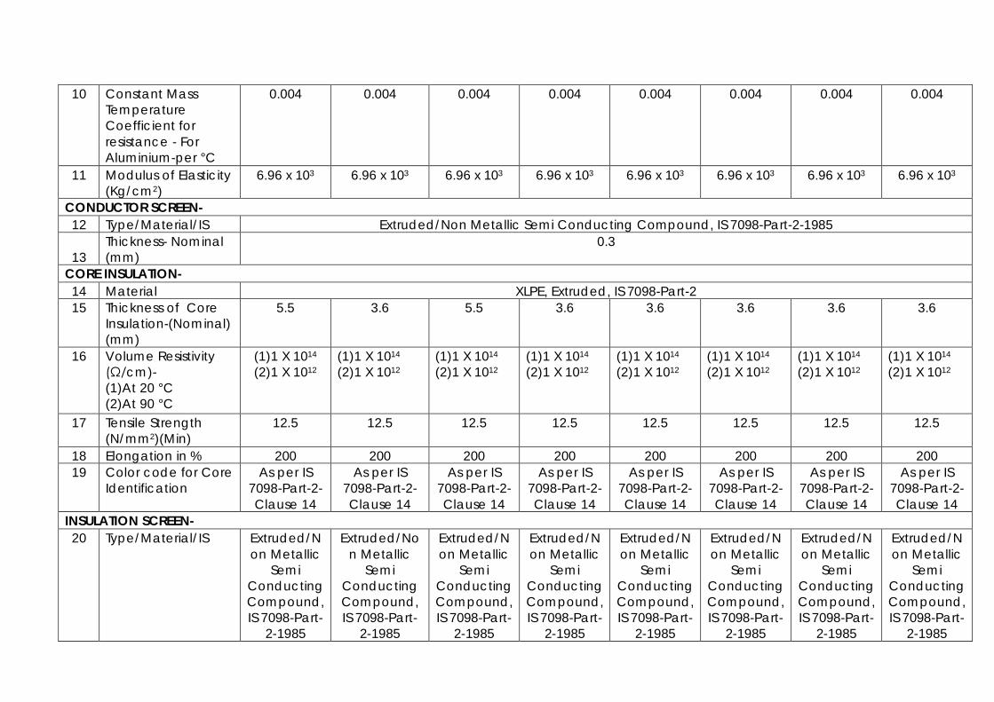
10 Constant Mass Temperature Coefficient for resistance - For Aluminium-per °C
0.004 0.004 0.004 0.004 0.004 0.004 0.004 0.004
11 Modulus of Elasticity (Kg/cm2)
6.96 x 10³ 6.96 x 10³ 6.96 x 10³ 6.96 x 10³ 6.96 x 10³ 6.96 x 10³ 6.96 x 10³ 6.96 x 10³
CONDUCTOR SCREEN- 12 Type/Material/IS Extruded/Non Metallic Semi Conducting Compound, IS 7098-Part-2-1985
13 Thickness- Nominal (mm)
0.3
CORE INSULATION- 14 Material XLPE, Extruded, IS 7098-Part-2 15 Thickness of Core
Insulation-(Nominal) (mm)
5.5 3.6 5.5 3.6 3.6 3.6 3.6 3.6
16 Volume Resistivity (Ω/cm)- (1)At 20 °C (2)At 90 °C
(1)1 X 10¹⁴
(2)1 X 10¹² (1)1 X 10¹⁴
(2)1 X 10¹² (1)1 X 10¹⁴
(2)1 X 10¹² (1)1 X 10¹⁴
(2)1 X 10¹² (1)1 X 10¹⁴
(2)1 X 10¹² (1)1 X 10¹⁴
(2)1 X 10¹² (1)1 X 10¹⁴
(2)1 X 10¹² (1)1 X 10¹⁴
(2)1 X 10¹²
17 Tensile Strength (N/mm2)(Min)
12.5 12.5 12.5 12.5 12.5 12.5 12.5 12.5
18 Elongation in % 200 200 200 200 200 200 200 200 19 Color code for Core
Identification As per IS
7098-Part-2-Clause 14
As per IS 7098-Part-2-Clause 14
As per IS 7098-Part-2-Clause 14
As per IS 7098-Part-2-Clause 14
As per IS 7098-Part-2-Clause 14
As per IS 7098-Part-2-Clause 14
As per IS 7098-Part-2-Clause 14
As per IS 7098-Part-2-Clause 14
INSULATION SCREEN- 20 Type/Material/IS Extruded/N
on Metallic Semi
Conducting Compound, IS 7098-Part-
2-1985
Extruded/Non Metallic
Semi Conducting Compound, IS 7098-Part-
2-1985
Extruded/Non Metallic
Semi Conducting Compound, IS 7098-Part-
2-1985
Extruded/Non Metallic
Semi Conducting Compound, IS 7098-Part-
2-1985
Extruded/Non Metallic
Semi Conducting Compound, IS 7098-Part-
2-1985
Extruded/Non Metallic
Semi Conducting Compound, IS 7098-Part-
2-1985
Extruded/Non Metallic
Semi Conducting Compound, IS 7098-Part-
2-1985
Extruded/Non Metallic
Semi Conducting Compound, IS 7098-Part-
2-1985

21 Semi Conductor-Thickness- Nominal (mm)
0.3 0.3 0.3 0.3 0.3 0.3 0.3 0.3
22 Metallic Part/Shield-Copper Tape-(Nominal)(mm)
0.045 0.045 0.045 0.045 0.045 0.045 0.045 0.045
FILLER- 23 Type/Material/IS ST-2/Non-
Hydroscopic/PVC IS 5831-1984
ST-2/Non-Hydroscopic/PVC IS 5831-
1984
ST-2/Non-Hydroscopi
c/PVC IS 5831-1984
ST-2/Non-Hydroscopi
c/PVC IS 5831-1984
ST-2/Non-Hydroscopi
c/PVC IS 5831-1984
ST-2/Non-Hydroscopi
c/PVC IS 5831-1984
ST-2/Non-Hydroscopi
c/PVC IS 5831-1984
ST-2/Non-Hydroscopi
c/PVC IS 5831-1984
24 Suitable for operating temperature of cable
Yes Yes Yes Yes Yes Yes Yes Yes
25 No. of Fillers provided including central filler
10 10 10 10 10 10 10 10
INNER SHEATH- 26 Material PVC,
Extruded, Type-ST-2
PVC, FRLS, Extruded, Type-ST-2
PVC, Extruded, Type-ST-2
PVC, FRLS, Extruded, Type-ST-2
PVC, FRLS, Extruded, Type-ST-2
PVC, FRLS, Extruded, Type-ST-2
PVC, FRLS, Extruded, Type-ST-2
PVC, FRLS, Extruded, Type-ST-2
27 Thickness of PVC Inner Sheath-(Minimum)(mm)
0.7 0.7 0.7 0.7 0.7 0.6 0.7 0.7
28 Tensile Strength (N/mm2)(Min)
12.5 12.5 12.5 12.5 12.5 12.5 12.5 12.5
29 Elongation in % 300 300 300 300 300 300 300 300 30 Color code for
Identification Black Black Black Black Black Black Black Black
OUTER SHEATH- 31 Material PVC,
Extruded, Type-ST-2
PVC, FRLS, Extruded, Type-ST-2
PVC, Extruded, Type-ST-2
PVC, FRLS, Extruded, Type-ST-2
PVC, FRLS, Extruded, Type-ST-2
PVC, FRLS, Extruded, Type-ST-2
PVC, FRLS, Extruded, Type-ST-2
PVC, FRLS, Extruded, Type-ST-2

32 Thickness of PVC Outer Sheath-(Minimum)(mm)
2.36 2.36 3.40 2.52 2.68 2.60 2.36 2.68
33 Tensile Strength (N/mm2)(Min)
12.5
34 Elongation in % 150 35 Color code for
Identification Black
ARMOUR- 36 Material/Type Galvanized Steel Flat Strip 37 Diameter Of Armour
Wire-(mm) (1)Nominal (2) Minimum
(1)0.85 x 4 (2)0.8 x 4
38 Resistance at 20 °C (Ω/KM)(Max)
2.45 2.03 2.03 1.78 1.63 As per IS 2.03 1.63
39 Tensile Strength (N/mm2)(Min)
As per IS
40 Elongation in % As per IS 41 Density at 20 °C
(Gm/Cu-Cm) 7.78
42 Coefficient of Linear Expansion per °C
19.5 x 10⁻⁶
43 Modulus of Elasticity (Kg/sq.cm)
As per IS
44 Overall Diameter of Armour-(mm)(min)
As per IS
GENERAL- 45 Overall Diameter of
cable-(mm)(min) 65 63 72 68 73 55 63 73

46 Continuous Current Rating (Amp)- (1) In Ground (2) In Duct (3) In Air
(1)220 (2)190 (3)260
(1)275 (2)240 (3)335
(1)275 (2)240 (3)335
(1)315 (2)275 (3)395
(1)355 (2)310 (3)450
(1)710 (2)610
(3)1100
(1)275 (2)240 (3)335
(1)355 (2)310 (3)450
47 Short Time Current Rating for 1 Sec. (KA)
11.30 17.50 17.50 22.60 28.30 94.30 17.50 28.30
48 Approximate Reactance per 1000 m at 50 Hz (Ω)
0.112 0.087 0.105 0.085 0.082 0.087 0.087 0.082
49 Approximate Capacitance per 1000 m at 50 Hz (μF)
0.22 0.36 0.26 0.41 0.46 0.82 0.36 0.46
50 AC Resistance at 90º C ((Ω/KM)
0.324 0.210 0.210 0.160 0.130 0.037 0.210 0.130
51 Extrusion Method Triple 52 Safe Pulling Force -
(Kg/mm2) 3 Kg/mm2
OR 30 N/mm2
53 Minimum Radius of Insulation
15 x Outer Diameter of Cable
54 Length per Drum (meter)- (1)Nominal (2)Maximum (3)Minimum
(1)500 (2)525 (3)475
(1)500 (2)525 (3)475
(1)500 (2)525 (3)475
(1)500 (2)525 (3)475
(1)500 (2)525 (3)475
(1)500 (2)525 (3)475
(1)500 (2)525 (3)475
(1)500 (2)525 (3)475

SCHEDULE – C7 GURANTEED TECHNICAL PARTICULARS
(To be filled by the Bidder) The Guaranteed Technical particulars furnished below for each size of cable shall be duly attested by the Bidder. Any correction / alterations in this GTP will lead to outright rejection of the Bid. Blank Space shown in the Column of details shall be furnished by bidder invariably. In no case any column should be left blank.
HT CABLE 1 2 3 4 5 6 7 8 9 10
SR. NO
DESCRIPTION 3C X 120 mm2
3C X 185 mm2 (WTPS)
3C X 185 mm2 (UTPS)
3C X 240 mm2
3C X 300 mm2 (WTPS)
1C X 1000 mm2
3C X 185 mm2 (UTPS)
3C X 300 mm2 (UTPS)
1 Voltage Grade(VOLT)
2 Suitable for earthed or unearthed system
CONDUCTOR- 3 Material 4 Shape 5 No. of strands per
core
6 Diameter Of the conductor-(mm)
7 Cross-sectional area(mm2)- (1)Nominal (2)Minimum
8 Resistance at 20 °C (Ω/KM)(Max)
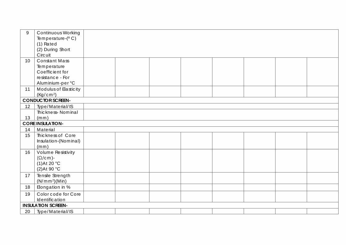
9 Continuous Working Temperature-(º C) (1) Rated (2) During Short Circuit
10 Constant Mass Temperature Coefficient for resistance - For Aluminium-per °C
11 Modulus of Elasticity (Kg/cm2)
CONDUCTOR SCREEN- 12 Type/Material/IS
13 Thickness- Nominal (mm)
CORE INSULATION- 14 Material 15 Thickness of Core
Insulation-(Nominal) (mm)
16 Volume Resistivity (Ω/cm)- (1)At 20 °C (2)At 90 °C
17 Tensile Strength (N/mm2)(Min)
18 Elongation in % 19 Color code for Core
Identification
INSULATION SCREEN- 20 Type/Material/IS

21 Semi Conductor-Thickness- Nominal (mm)
22 Metallic Part/Shield-Copper Tape-(Nominal)(mm)
FILLER- 23 Type/Material/IS 24 Suitable for
operating temperature of cable
25 No. of Fillers provided including central filler
INNER SHEATH- 26 Material 27 Thickness of PVC
Inner Sheath-(Minimum)(mm)
28 Tensile Strength (N/mm2)(Min)
29 Elongation in % 30 Color code for
Identification
OUTER SHEATH- 31 Material 32 Thickness of PVC
Outer Sheath-(Minimum)(mm)
33 Tensile Strength (N/mm2)(Min)
34 Elongation in %
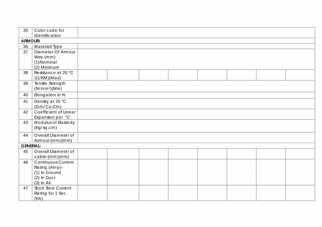
35 Color code for Identification
ARMOUR- 36 Material/Type 37 Diameter Of Armour
Wire-(mm) (1)Nominal (2) Minimum
38 Resistance at 20 °C (Ω/KM)(Max)
39 Tensile Strength (N/mm2)(Min)
40 Elongation in % 41 Density at 20 °C
(Gm/Cu-Cm)
42 Coefficient of Linear Expansion per °C
43 Modulus of Elasticity (Kg/sq.cm)
44 Overall Diameter of Armour-(mm)(min)
GENERAL- 45 Overall Diameter of
cable-(mm)(min)
46 Continuous Current Rating (Amp)- (1) In Ground (2) In Duct (3) In Air
47 Short Time Current Rating for 1 Sec. (KA)

48 Approximate Reactance per 1000 m at 50 Hz (Ω)
49 Approximate Capacitance per 1000 m at 50 Hz (μF)
50 AC Resistance at 90º C ((Ω/KM)
51 Extrusion Method 52 Safe Pulling Force -
(Kg/mm2)
53 Minimum Radius of Insulation
54 Length per Drum (meter)- (1)Nominal (2)Maximum (3)Minimum
Name of Bidder: ______________ Signature of the Bidder: ___________
Name : __________________________ Date: _________________________ Designation: ______________________ Authorized common rubber Stamp / seal of the bidder:_________