technical tm x-2094 memorandum · pdf filei nasa technical nasa tm x-2094 memorandum ......
TRANSCRIPT

I N A S A T E C H N I C A L NASA TM X-2094 MEMORANDUM
COLD-AIR INVESTIGATION OF A TURBINE WITH TRANSPIRATION-COOLED STATOR BLADES
I - Performance of Stator With Discrete Hole Blading
by Herman W: &'rat, Jr., Harold J. Schum, I and Edwdrd M , Sza~c&
Lewis Research Ceater CEweddnd, Ohio 44135
https://ntrs.nasa.gov/search.jsp?R=19700030523 2018-05-12T07:33:02+00:00Z

Lewis Research Center
Technical Memorandum
Washington, D. C. 20546
The effects of transpiration coolant ejection on stator mass flow and efficiency were
experimentally determined for ratios of coolant to primary mass flow from 0 to 7percent.
The results showed that transpiration coolant discharge caused a decrease in total mass
flow and efficiency. When compared with previously obtained experimental results for
trailing-edge discharge, the performance loss for transpiration discharge was signifi-
cantly larger. The predicted decrease in efficiency resulting from transpiration dis-
charge was less than the experimental decrease.
Gas turbine
Transpiration cooling
*For s a l e by the Clearinghouse for Federal Scientific and Technical Information Springfield, Virginia 22151

COLD-AIR INVESTIGATION OF A TURBINE WITH
TRANS PIRATION-COOLED STATOR BLADES
I - PERFORMANCE OF STATOR WITH D I S C R a E HOLE BLADING
by H e r m a n W. Prust , J r . , Haro ld J. S c h u m , a n d Edward M. Szanca
Lewis Research C e n t e r
SUMMARY
At the NASA Lewis Research Center, the effects on turbine performance of different
means of stator-blade coolant ejection a r e being investigated. This report presents the
resul ts of a detailed experimental and analytical investigation of the effects on stator performance of stator-blade transpiration coolant discharge. The blading investigated had discrete cooling holes in the outer surface. The investigation included the effects on
s tator mass flow and efficiency over a range of coolant mass flows from 0 to about 7 per-
cent of primary mass flow. Relative to the zero-coolant-flow results with the coolant holes sealed, the experi-
mental results showed that the transpiration discharge of coolant caused a small decrease in total mass flow and primary air efficiency and a quite large decrease in thermody-
namic efficiency. (The primary air efficiency relates the actual kinetic energy output to the ideal energy of the primary flow only; the thermodynamic efficiency charges the stator with the ideal energy of both the pr imary and coolant flows.) Over the range of coolant
Slows of practical interest, from about 3 to 7 percent, the decrease in total mass flow was a nearly constant value of 1. 5 percent; the decrease in primary air efficiency was nearly constant at about 1 .0 percent; and the decrease in thermodynamic efficiency was about
1 4. 5 and 12.5 percent, respectively, at 3q and 7 percent coolant flow. When compared
with corresponding efficiency results for stator blade trailing-edge coolant discharge,
the penalty in efficiency for stator transpiration coolant discharge is large. The large
penalty for transpiration coolant discharge relative to trailing-edge discharge is caused by the difference in location and direction of coolant discharge for the two methods.
A comparison was made of predicted and experimental effects of transpiration dis - charge on primary air efficiency over the coolant flow range between 3 and 7 percent.
Relative to the efficiency with zero coolant and the holes sealed, the predicted results showed about a 1/4-percent gain in primary air efficiency. The experimental results
showed about a 1-percent Boss in primary air efficiency.

INTRODUCTION
To meet their performance requirements, many advance gas turbine engines must operate at high turbine inlet temperatures. In some cases, these temperatures a r e high enough that the turbine blading must be cooled to avoid exceeding the s t r e s s and oxidation limitations of currently available materials. The general method for cooling the blading is to bleed air from the compressor, direct it through the turbine blading for cooling, and then discharge it f rom the blading into the main gas s t ream. The means of dis- charging the coolant from the blading into the main gas stream a r e different for different cooled blade designs. In reference 1, an analysis is presented which indicates that dif - ferent means of coolant ejection affect turbine performance quite differently. To confirm
these findings experimentally, an investigation is being conducted a t the NASA Lewis Research Center to determine the effect on turbine blade row and stage performance of several means of coolant discharge that a r e typical of different cooled blade designs.
The f i r s t coolant discharge method investigated was stator -blade trailing-edge e jec - tion. In that investigation, the coolant was discharged into the main gas stream through a slot along the entire length of the stator-blade trailing edge. The results of the investi- gation, which include the effects of stator-blade trailing-edge ejection on both stator and stage performance, a r e reported in references 2 to 4. The results show that the flow of
coolant caused only small changes in both stator and stage thermodynamic efficiency. From the stator and stage results, it was also deduced that the rotor efficiency was not significantly affected by the flow of coolant.
An investigation of the effect of stator-blade transpiration coolant ejection on turbine
stator and stage performance is now being made. The stator investigation of the initial type of transpiration blading is complete. (Except for trailing-edge geometry, the pro- files and primary flow path of this blading a r e the same, within manufacturing tolerance, as those used for the investigation of trailing-edge discharge.) With transpiration cool-
ing, the coolant is introduced into hollow blades and then ejected through a porous shell
that constitutes the entire outer blade surface. The particular blading tested has discrete cooling holes with variable porosity over the blade surface and a self-supporting shell. The self-supporting shell is somewhat unusual in that i t eliminates the need for support s t ruts with separate chambers and metering orifices associated with the more common wire -mesh shell-type transpiration-cooled blading.
This report presents the results of a detailed investigation of the performance of the
described stator with self -supporting, variable -porosity, transpiration-type blading.
The results include the effects of transpiration coolant discharge on stator mass flow characteristics, outlet flow angle, pressure loss patterns downstream of the blading, specific output, and overall efficiency. Selected results for the subject stator a r e also
compared with corresponding results for the stator having trailing-edge ejection of

coolant flow. In addition, the experimental effects of transpiration coolant discharge on
s tator efficiency a r e compared with predicted effects. During this investigation, the inlet temperature of the primary and coolant flow was
the same, so the results include no actual coolant effects. The results a r e for nominal coolant flow rates of 0, 3, 5, and 7 percent of the primary mass flow. Mass flow and outlet flow angle results were obtained for a range of stator-inlet to downstream pres- su re ratios, while stator output and efficiency results were obtained at a constant s ta tor inlet-to-downstream hub pressure ratio of 1.72, corresponding to s tator design con- ditions (ref. 5).
S YNI B OLS
Ah specific kinetic energy output, Btu/lb; kg
Ahpr stator kinetic energy output per unit of primary air mass flow, Btu/lb; k kg
Ahtot stator kinetic energy output per unit of total (primary plus coolant) mass flow, Btu/lb; kg
P pressure, psi; N/m 2
V absolute gas velocity, ft/sec; m/sec
w mass flow rate, lb/sec; kg/sec
Y coolant fraction, ratio of coolant to pr imary mass flow
a! flow angle at blade outlet measured from axial direction, deg
6 ratio of stator inlet pressure to U. S. standard sea-level pressure
6 displacement thickness parameter; loss in flow as fractional part of ideal flow
77 s tator efficiency
7 7 ~ s tator primary a i r efficiency; stator kinetic energy output expressed as fraction
of ideal energy of primary flow only
qt stator thermodynamic efficiency; stator kinetic energy output expressed as frac- tion of ideal energies of both primary and coolant flows
'cr squared ratio of critical velocity at stator inlet to crit ical velocity of U. S. stand- a rd sea-level air
Subscripts :
ave average of hub and tip conditions
c coolant flow

0
OP
P
tot
blade coolant holes closed
conditions at Mach 1
measuring station downstream of blading
blade hub
ideal quantity corresponding to isentropic process
absence of coolant flow
blade coolant holes open
primary flow
total flow (primary plus coolant flow)
0 measuring station upstream of blading
1 measuring station at stator throat
2 measuring station just downstream of stator trailing edge
3 station where complete mixing occurs
3d three dimensional o r annular sector
Superscript:
1 total state
APPARATUS
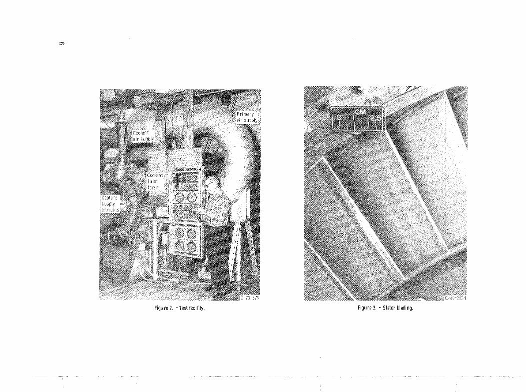
The apparatus used in the investigation consisted of the test stator and an appropriate
tes t facility. The facility, which is shown in the sketch of figure 1 and the photograph of figure 2, is the same as that described in reference 3.
The s tator blading of the subject investigation is shown in figure 3. The blading is
hollow cored with self-supporting porous walls. The outer surface of the blading has a large number of discrete small circular holes. The flow path of the coolant is from the hollow core of the blading, through the permeable blade walls, and out these holes at varying rates over different par ts of the blade surface. Figure 4 shows the mean-section profile and flow path of the blading. The profiles and primary air flow path of this blading a r e the same, within manufacturing tolerance, as those of the stator blading described in detail in reference 5 and also the same, except for trailing-edge geometry, a s those of
the stator blading used to investigate stator-blade trailing-edge ejection of coolant flow (refs. 2 and 3). The following a r e significant dimensions of the blading: 30-inch (76.2 -

Figure 1. -Cross section of test facility.

Turb ine
1.63 in. (4.14 cm) -4
Figure 4. - Blade mean-section profi le and flow path..
cm) tip diameter, 4.0-inch (10. 16-cm) radial height, 2.26-inch- (5. 74-cm -) mean- radius chord, and 1.63-inch- (4.14-cm -) mean-radius pitch.
INSTRUMENTATION
The instrumentation required for obtaining the reported results is the same as that
described in reference 3. Briefly, a Dall-tube flowmeter was used to measure the
pr imary flow rate , and a Venturi meter was used to measure the coolant flow rate. In the stator tes t section, total and static pressures were measured a t the locations shown in figures 5 and 6. Inlet total pressures were measured with Kiel-type total pressure probes; downstream total pressures were measured with a total pressure survey probe
of the modified type described in detail in reference 6; and static pressures were meas-
ured using conventional static pressure taps.


Static pressure tap
, \-
Probe l imit -' Probe l imit
Figure 6. -Circumferential total pressure survey area with approximate location of wall static pressure taps.
TEST AND CALCULATION PROCEDURES
The fluid used in the investigation for both the pr imary and coolant flow was labor-
atory combustion air at a total temperature of about 545' F (303 K). The stator-inlet 5 2 pressure of the primary air was 30 inches of mercury absolute (1.0159x10 ~ / m abs).
Mass flow characteristics and outlet flow angle results were obtained for a desired range of overall stator pressure ratios pb/Pd, and coolant flow rates. Pressure
ratios were set by holding the upstream pressure constant and adjusting the downstream
pressure. At each pressure ratio setting, the coolant m a s s flow rate was varied by regulating the inlet pressure of the coolant. The stator-outlet flow angles were meas- ured by traversing radially across the blade span with the probe situated midway be-
tween wakes. When the flow angles were measured, the probe was located about 0 .5 inch (1.27 cm) axially downstream of the stator-blade trailing edge.
Stator output and efficiency results were obtained at a constant overall stator hub pressure ratio of 1. 72, corresponding to design conditions for the stator of reference 5,
with nominal coolant flow rates of 0 , 3, 5, and 7 percent of the primary flow. At each coolant flow rate, annular surveys of total pressure loss were made for approximately one blade pitch (fig. 6). These annular surveys were made by conducting circumferential surveys at a sufficient number of different radii to define adequately the loss for the
complete annular sector. At zero-coolant flow, two annular surveys were conducted. For one of these su r -
veys, the blade coolant holes were filled and smoothed flush to the outer blade surface. The purpose of this survey was to determine the performance of the stator without cool- ant provisions. En the other survey with zero-coolant flow, the blading was unaltered; that is, the coolant holes were left open. Under these conditions, some of the primary air flows through the interior of the blading. This condition of operation is unrealistic for transpiration-cooled blading, so the results would normally be only of academic

interest. However, for this investigation, the results were also of practical use, as now described.
To determine the stator mass flow with the coolant holes sealed using Dall-tube measurements would have required that all 50 blades of the stator be sealed, since the Dall-tube flow includes the flow to all blading. To seal all blades would have required a complete stator disassembly and reassembly. The stator mass flow with coolant holes sealed was therefore obtained by an indirect method that required that only three blades in the total pressure survey a rea be sealed. This modification was accomplished without disassembling the stator.
Briefly, the indirect procedure consisted of the following: mass flow results for zero-coolant flow with the coolant holes open were f i rs t determined from Dall-tube
measurements. Then, the ratio of the actual mass flow to the ideal m a s s flow was de- termined for zero-coolant flow both with the coolant holes open and with the coolant holes
sealed. These ratios were determined from annular-sector total pressure loss data using the procedures described in reference 7. Knowing the stator flow for zero coolant
with the holes open and the ratio of actual to ideal stator flow for zero coolant with the holes both open and sealed made i t possible to compute the stator mass flow with coolant
holes sealed:
where 6") the displacement thickness parameter, represents the fractional loss in ideal
flow of the blade row (see ref. 7). Except for the results with the coolant holes sealed, the test and calculation pro-
cedures used in determining the s tator mass flow results were those conventionally used for Venturi- and Dall-tube-type flowmeters. Output and efficiency results were deter- mined using the procedures summarized in reference 3.
The predicted effect of transpiration discharge on stator output was obtained by using the following assumptions and procedures:
(1) The coolant flow rate per unit of blade surface was constant.
(2) Since the velocity of coolant at the point of discharge on the blade surface is gen- erally perpendicular to that of the main gas s t ream, the dynamic head of the coolant at the point of discharge is lost.
(3) The coolant-flow ideal available energy, corresponding to the static head between
the point of discharge on the blade surface and blade exit conditions, is converted to
useful kinetic energy at the same efficiency as the primary flow. (4) The coolant flow and the primary flow mix downstream of the blade trailing edge.

(5) The efficiency of the primary flow is unaffected by the flow of coolant. With the use of these assumptions and blade mean-section. data, an integration was
first made of the gain in. kinetic energy output resulting from the expansion of the coolant
from static conditions on the blade surface to the blade exit, the static conditions on the blade surface being obtained from the theoretical blade surface pressure distribution
presented in reference 5. Next, an integration was made of the loss in kinetic energy output resulting from mixing the primary flow with the lower velocity coolant flow. The
integrated effects of the coolant expanding and mixing with the primary flow were then
summed to obtain the net output of the coolant flow.
RESULTS AND DISCUSSION
The investigation of the effects on stator performance of transpiration discharge of
coolant through a self -supporting porous blade wall was made for nominal coolant flow
rates of 0, 3, 5, and 7 percent of the primary flow. Mass flow and outlet flow angle
results were obtained fo r a range of stator-inlet to downstream pressure ratios, while
stator output and efficiency results were obtained at a constant stator-inlet to downstream hub pressure ratio of 1.72, which corresponded to stator design conditions (ref. 5).
To determine the effect of coolant discharge on the performance of a stator requires that the base noncooled stator performance be established. This base performance should
exclude both the effect of coolant ejection and the effect of any blade modifications r e -
quired for coolant flow. For the subject blading, apertures in the blade surface a r e required for coolant flow.
With zero-coolant flow, these holes, if left open, would permit some of the primary air to blow through the blading and would present surface discontinuities in the pr imary flow path that a r e not present in noncooled blading. Therefore, in the subject investigation,
when establishing the performance of the noncooled stator on which the effect of t rans-
piration coolant discharge is based, the coolant holes in the outer blade wall were sealed to prevent pr imary flow through the walls, and the surface was then smoothed flush t o the outer blade wall to eliminate the surface discontinuities of the coolant holes.
The minimum transpiration cooling rate presented in the results is approximately 3 percent of the primary flow. This represents a minimum practical value of coolant rate for this blading and occurs when the coolant pressure inside the blading is slightly
3 higher (-1 in. of Hg o r 3.38X10 ~ / m ~ ) than the highest pressure on the blade surface
(inlet stagnation pressure). Values of coolant pressure lower than stator primary air inlet stagnation pressure with corresponding lower cooiant rates represent unrealistic operating conditions since some of the primary air flows abnormally through the interior
of the blading.

The results a r e presented in three sections. The f i r s t section presents the experi- mental results for the subject stator. The second section compares the experimental
results for the subject stator with similar results for the stator of reference 3 having
trailing-edge coolant ejection. The last section compares the experimentally determined results for the subject stator with those predicted analytically.
Experimentally Determined Effects of Transpiration Coolant
Discharge on Stator Performance
The f i rs t part of this section concerns mass flow characteristics; the second part concerns pressure loss and stator output; and the third part relates to stator efficiency.
Effect of transpiration coolant discharge on stator mass flow characteristics. - The experimental mass flow of the stator with transpiration coolant flow is presented in fig-
ure 7. In figure 7(a), the equivalent primary a i r mass flow is shown as a function of the ratio of inlet total to average downstream pressure pb/pd, ave and coolant flow. The dashed curves at zero-percent coolant flow with the blade coolant holes open and at 3.5-,
5.0 -, and 7.0 -percent coolant flow were obtained from the crossplots of experimental weight flow data. The data for zero coolant with the blade coolant holes closed were ob- tained indirectly as described under TEST AND CALCULATION PROCEDURES. The solid curve shown was extrapolated from a single test point. From the figure, a trend
of decreasing primary flow with increasing coolant flow is evident. The flow for zero
coolant with the coolant holes open is also a little less than the flow with the coolant holes
sealed. In figure 7(b), the same flow data as shown in figure 7(a) a r e presented a s a function
of the average throat pressure ratio Pb/P1, ave. As in figure 7(a), a trend of decreasing primary flow with increasing coolant flow is evident. Examination of the data of fig-
ure 7(b) shows that, at a constant throat pressure ratio, the decrease in primary flow with coolant addition, relative to the flow with the coolant holes sealed, is a little larger
than the increase in coolant flow. There is, therefore, a decrease in total flow with the
flow of coolant. In figure 8, the fractional decrease in total flow relative to the flow with the coolant
holes sealed is shown as a function of coolant flow rate. The data shown a r e for a con-
stant throat pressure ratio near stator design conditions. These results show the total flow to decrease about 1 . 5 percent between 0- and about 3-percent coolant flow. From about 3- to 7-percent coolant, which is the practical range of coolant flows for this blading, the percentage decrease in total flow remains nearly constant at 1. 5 percent.
With transpiration discharge, a decrease in total flow with coolant addition is not

Coolant flow rate, Y
- Coolant holes sealed
24 1 ' 1 I I 1.0 1.2 1.4' 1.6 1.8 2.0 2.2 2.4
Average overall pressure ratio, pbIpd, ave
(a) Based on average overall pressure ratio.
Average throat pressure ratio, pblpl, ave
(b) Based on average throat pressure ratio.
Figure 7. - Mass flow of stator with transpiration coolant.

Coolant holes sealed +- m 1
-Coolant holes open - - m -------
u -. 04
0 .01 .02 .03 .04 .05 .06 .07 Coolant flow rate, y
Figure 8. - Fractional variation i n total mass flow as funct ion of transpiration coolant flow rate.
unexpected. Most of the coolant flow is added upstream of the throat, so the throat flow is about equal to the total of the primary and coolant flows. If the average throat ve- locity of the coolant were the same as that of the primary flow without coolant, the total flow would be constant for equivalent primary flow conditions and throat pressure ratio.
However, at the throat, the average velocity of the coolant must be l e s s than that of the primary flow. The reason is that the total pressure of the coolant in the direction of primary flow at the point of discharge on the blade surface is always less than the inlet total pressure of the primary flow. Therefore, the total flow is decreased with coolant
addition. In figure 8, a reduction in flow of about 1 . 5 percent, with zero-coolant flow and the
holes open, is shown relative to the flow with coolant holes sealed. This reduction in
flow was expected since, with the holes open, part of the flow is expanding inefficiently
through the porous blading, whereas, with the holes closed, all the flow is expanding through the design flow path of the blading.
The stator outlet flow angles a obtained at the design outlet hub critical velocity
ratio ( v / v , ~ ) ~ , with various coolant fractions a r e shown in figure 9. (The data points
Nominal coolant flow rate,
Y n 0 D .03 0 -05
Hub Fraction of blade height
Tip
Figure 9. - Effect of coolant flow rate o n stator free-stream outlet flow angle at design outlet h u b cr i t i ca l velocity rat io of 0.896.

shown were obtained from curves faired through average experimental free-stream angle
t races . ) The outlet flow angles a r e little, if at all , affected by coolant addition. Since,
from continuity considerations, very small changes in flow angle will accommodate small
changes in total flow, these results a r e consistent with those discussed in the last para- graph which showed the total flow to vary only about 1 . 5 percent with coolant addition.
Effect of t r ans~ i r a t ion coolant discharge on pressure loss patterns a t blade exit and
on kinetic energy loss. - The effect of transpiration discharge of coolant on wake pres- sure loss t races is shown in figure 10. The results shown a r e for a constant stator-inlet
Coolant flow, percent
0 (Holes sealed)
VI V)
3 One blade pitch _I Figure 10. - Comparison of pressure loss data with different coolant flow rates.
Data measured at blade mean radius.
to downstream hub pressure ratio of 1 . 7 2 corresponding to s tator design conditions
(ref. 5). (The t races presented a r e from circumferential t raverses measured at the blade mean section to exclude the influence of end wall losses. ) In this figure, the t races for 3-, 5-, and 7 -percent nominal coolant flow a r e superimposed on the t race for 0-percent coolant flow to show the manner in which the wake patterns changed with cool-
ant flow. The size of the wake a rea indicates the loss in specific kinetic energy of the total flow Ahtot = (W Ah + wchhc)/(w + w c ) That i s , as the wake a rea increases, the
P P P specific kinetic energy output of the total flow decreases. The wake a rea with zero cool- ant and the coolant holes open is larger than that with the holes closed. Therefore, re l- ative to the loss with the holes sealed, an additional loss is incurred with the holes open
as a result of some of the primary a i r leaking through the interior of the blading and/or the surface discontinuities of the coolant apertures.
With increasing coolant flow, the wake area (fig. 10) also continually increases, so

the specific energy of the total flow decreases with increased coolant flow. The figure
also shows that the increase in wake a rea occurs on the suction side of the blading. Possible implications of this will be discussed later in this section.
The decrease in specific output of the total flow is shown quantitatively in figure 11. These results, which a r e based on annular data, show the amount of decrease to be a little greater than the coolant fraction and, therefore, quite large at the larger coolant flows. For instance, at 5-percent coolant flow, the decrease in specific output of the total flow is 5. 8 percent, and at 7-percent coolant flow, the decrease is 7.7 percent.
A better understanding of the effect of transpiration coolant ejection on stator output can be obtained from figure 12. In this figure, the fractional variation in specific output based on pr imary flow, instead of on total flow, is presented as a function of coolant flow rate. Relative to the results with the coolant holes sealed, the specific output per unit
of primary flow Ah = (w Ah + wc~hc) /w decreases about 1 .0 percent at 3-percent Pr P P P
coolant flow and then remains constant with increased coolant flow. This decrease is
most significant since it indicates that any increase in output resulting from the flow of
- I ,,-Coolant holes open
Coolant f low rate, y
F igure 11. - Var ia t ion in stator specific output, based o n total flow, w i th coolant f low rate.
,-Coolant holes sealed 0 c+
Coolant f low rate, y
F igure 12. - Var iat ion in stator specific output, based o n p r i - mary flow, w i th coolant f low rate.

coolant is more than offset by a decrease in output due to the coolant flow mixing and in-
terferring with the primary flow. Possible reasons for this occurrence a r e discussed in the following two paragraphs.
With transpiration cooling, the direction of the coolant at the point of discharge is generally perpendicular to the direction of the main gas stream. Therefore, at the point of injection, the coolant flow, having a nominally zero component of velocity in the
direction of the main gas s t ream, contributes little, if any, useful energy to the flow.
After being injected into the main gas s t ream, the coolant possesses ideal available energy corresponding to the static head between the point of discharge and the blade exit. However, on the suction surface of the blading, in the a r e a of diffusion, this static head
is not positive, but negative, since the static pressure at the point of discharge is less than the static pressure at the blade exit. As shown in reference 5, figure 13, fo r blading with this geometry, the diffusion a r e a represents a considerable portion of the
total blade surface. To discharge flow perpendicular to the main gas s t ream, at low velocity, in a negative pressure gradient would seem to contribute to a thickening (and
possibly separation) of the boundary layer of the main gas stream. Some evidence that the flow of coolant causes such a loss was shown in figure 10, which indicated that the increase in wake a r e a with increased coolant flow occurred on the suction (diffusion)
side of the blading. It is also possible that the ejection of the coolant increases the friction loss of the pr imary flow, since the coolant jets may act as surface imperfections.
On the portion of the blade surface having positive static head between the point of
coolant discharge and blade exit, the static head of the coolant is converted, at some efficiency, into kinetic energy that contributes to the useful output of the blade row. However, as discussed previously in the section Effect of transpiration coolant discharge on stator mass flow characteristics, the velocity of all portions of the coolant after ex- pansion is l e s s than that of the primary flow. As a result, some of the useful output of the blade row is lost because of the coolant flow mixing with the primary flow.
As shown in figure 12, the net result of the effects discussed in the preceding two paragraphs is that any increase in output resulting from the expansion of the coolant is
more than offset by a reduction in output caused. by the coolant flow mixing and interfering
with the main gas stream Effect of transpiration coolant discharge on stator efficiency. - These results a r e
presented in t e rms of both a primary a i r efficiency rll, and a thermodynamic efficiency q. The primary air efficiency relates the actual k ina i c energy of the primary and
coolant flows to the ideal kinetic energy of the primary flow only, while the thermody- namic efficiency relates the same actual kinetic energy of the combined flows to the sum
of both the primary and coolant flow ideal energies. Values of thermodynamic efficiency
presented a r e based on charging the coolant flow with the ideal energy between the coolant
supply amulus and stator exit static pressure.

,-Coolant holes sealed
Coolant flow rate, y
Figure 13. - Variation i n stator pr imary a i r efficiency with coolant flow rate.
The variation of annular-sector after-mix primary air efficiency with transpiration
coolant flow rate is presented in figure 13. Relative to the efficiency with the coolant holes sealed, the figure shows that the primary air efficiency decreases about 1 percent at about 3-percent coolant and then remains about constant between coolant flow rates
of 3 and 7 percent.
The decreasing trend of pr imary air efficiency with coolant addition shown in fig- u re 13 can be explained with reference to figure 12. The primary air efficiency q is
P equal to the specific output based on primary flow Ah (see fig. 12) divided by the ideal
P r specific energy of the primary flow Ahi For this investigation, with a constant pr i -
2 P' mary air pressure ratio, the ideal specific energy of the primary flow is constant. Therefore, the primary air efficiency varies with coolant addition, just as the specific output based on pr imary flow varies for the same reasons.
In figure 14, experimentally determined values of annular-sector after-mix thermo-
,-Coolant holes sealed
-Coolant holes open . 97k
Coolant flovd rate, y
Figure 14; - Variation i n stator thermodynamic efficiency with coolant flovd rate.

dynamic efficiency qt, 3d, a r e shown as a function of coolant rate. The thermodynamic
efficiency decreases sharply with coolant flow rate. For instance, with the coolant 1 holes sealed the efficiency is 97. 5 percent. At 3x-percent coolant flow, the efficiency
is about 93 percent, and at 7-percent coolant flow, the efficiency is about 85. 5 percent, which represents decreases of about 4 .5 and 12.5 percent, respectively, relative to the efficiency with the holes sealed. The much larger decrease in thermodynamic efficiency
(fig. 14) relative t o the decrease in primary air efficiency (fig. 13), of course, results from the fact that the thermodynamic efficiency is charged with the coolant flow ideal
energy.
Comparison of Effects o n Stator Performance of Transpi ra t ion Coolant
Discharge and Trailing-Edge Coolant Discharge
The first part of this section compares the effects of the two discharge methods on
stator mass flow, and the last part compares the effects on stator overall efficiency. The trailing-edge coolant discharge data were previously obtained and reported in ref- erences 2 and 3. All data presented a r e near design stator pressure ratio.
Comparison of effects of transpiration and trailing-edge discharge on stator mass
flow. - Figure 15 presents the fractional variation in total and pr imary flow for the two -
Transpiration discharge Trailing-edge discharge
/ / -
/ ./-
/- Transpiration ,- /' Total flow
I coolant holes /-
Primary flow
$ ~ - T ~ ~ ~ ~ T . ---a- coolant holes open
P -.02 \, Total floiGv - m C .- -
-. 10 0 0 .01 .02 .03 .04 .05 .06 .07
Coolant flovv rate, y
Figure 15. -Comparison of variation i n mass flol!v as function of coolant flow rate for transpiration and trailing-edge cool- ant discharge.

discharge methods a s a function of coolant rate. As previously discussed with t rans-
piration ejection, the primary flow decreases at a rate that is a little larger than the
coolant flow rate , so the total flow is decreased a small amount with the addition of cool-
ant. With trailing-edge discharge of coolant, the variations in total and primary mass
flow as a function of coolant fraction a r e quite different from those with transpiration discharge. With trailing-edge ejection of coolant, the primary flow is decreased only slightly, s o the total flow increases significantly with increased coolant addition.
The principal reason for the different trends of the two methods of discharge is the different discharge locations. With transpiration discharge of coolant, most of the coolant is discharged upstream of the stator throat. The coolant then fills part of the available throat a r ea so the primary flow is reduced. With trailing-edge ejection, the
coolant is discharged downstream of the throat so the throat a r ea does not have to ac- commodate the coolant flow and the primary flow remains nearly constant.
Comparison of effect of trsnspiration coolant discharge and trailing-edge coolant
discharge on stator efficiency. - In figure 16, a comparison is presented of the fractional change in primary air efficiency as a function of coolant flow for both transpiration dis- charge and trailing-edge discharge of coolant. As with mass flow characteristics, the results a r e quite different for the two types of coolant discharge. With trailing-edge
discharge, the primary air efficiency increases with increasing coolant flow; with t rans-
Trail ing-edge discharge /
'-Transpiration coolant holes sealed ,-,
c- I
,/---
O r " 0 -. 02 'Transpiration discharge I " ~ r a n s p i r a t i o n coolant holes open
Figure 16. - Comparison of var iat ion in pr imary a i r eff iciency as func t ion of coolant flow rate for t ranspirat ion coolant dis- charge and trail ing-edge discharge.
-. 04 I I I 0 . 0 1 .02 .03 .04 .05 . 0 6 .07
Coolant flow rate, y

piration coolant discharge, the primary air efficiency is decreased because of coolant
flow. The different trends a r e caused primarily by the differences in the location and di-
rection of ejection of the coolant for the two types of discharge. With transpiration coolant discharge, the coolant is ejected generally perpendicular to the main flow and
so contributes little, if any, useful kinetic energy at the point of discharge. An increase in output can result because of the expansion of the coolant flow from the point of dis- charge. However, whatever portion of this output is realized, i t is more than offset by a reduction in output resulting from the coolant flow entering and mixing with the main
gas stream. The result is a net decrease in specific output per unit of primary flow. As discussed previously in the section Effect of transpiration coolant discharge on s tator
efficiency, fo r this investigation a given decrease in specific output per unit of primary flow is equivalent to the same decrease in primary a i r efficiency.
With trailing-edge ejection, the coolant is discharged at the downstream stagnation point of the blading and in the direction of primary flow. Since it is discharged at this location, the coolant flow has no apparent effect on the flow of the primary fluid, and, since it is discharged in the direction of flow, it contributes its kinetic energy to the
useful output of the primary fluid. In addition, as explained in reference 3, there is a reduction in trailing-edge loss with trailing-edge ejection, which increases the specific output. For these reasons, with trailing-edge ejection, the specific output based on primary flow and, consequently, the primary air efficiency, continually increases as the
coolant rate increases. Summarizing, the results of this section indicate that, with transpiration discharge,
the coolant flow contributes little, i f any, useful output to the stator blade row and has an adverse effect on the specific output of the primary flow. With trailing-edge discharge, the coolant flow contributes to the useful output of the stator and apparently has no harm- ful effect on the specific output of the primary flow.
In figure 17, the effect on stator thermodynamic efficiency of transpiration and
trailing-edge coolant discharge is compared. With transpiration discharge, the thermo- dynamic efficiency decreases rapidly with increased coolant flow, while with trailing- edge ejection, the thermodynamic efficiency f i rs t increases and then decreases.
Comparing the trend of thermodynamic efficiency of figure 17 with that of primary
a i r efficiency in figure 16 for either of the two discharge methods reveals that the trend of thermodynamic efficiency falls below the trend of primary air efficiency by an in- creasing amount with increased coolant flow. This occurs, of course, because the thermodynamic efficiency is charged with increasing amounts of coolant flow ideal energy a s the coolant flow is increased, and the primary air efficiency is not. Except for this fact, the reasons for the variations in trends in thermodynamic efficiency a r e the same a s the reasons for the variations in trends in primary air efficiency.

r Transpiration coolant holes sealed ~T ra i l i ng -edge -
0 % -' discharge .
-. 14 I.-..- -, 0 . 0 1 .02 .03 .04 .05 - 0 6 .07
Coolant flow rate, y
Figure 17. - Comparison of variation i n thermodynamic effi- ciency as funct ion of coolant flow rate for transpiration coolant discharge and trailing-edge discharge.
Comparison of Experimental and Predickd Effects of Transpiration
Coolant Ejection o n Stator Efficiency
In a preceding section, TEST AND CALCULATION PROCEDURES, an analytical
method for predicting the effect on stator efficiency of transpiration coolant discharge
was described. In figure 18, the fractional variation in primary air efficiency for the
Predicted - _ _ _ - - - - - ! $ [ I , I I I I , J Z
0 .-, Experimental
- 0 5 .$ -. " .- - .- g 5
L L
-. 04 0 . 0 1 ;02 .03 .04 .05 .06 .07
Coolant flow rate, y
Figure 18. - Comparison of experimental and predicted changes i n primary a i r efficiency for transpiration coolant discharge.

subject stator, predicted by using the described analytical method, is compared with the
experimentally determined variation. In the range of coolant flows of interest, between 3 and 7 percent, the predicted results show about a 1/4-percent gain in primary air efficiency, whereas the experimental results show about a 1-percent loss in primary air efficiency. The predicted results indicate that the coolant flow contributes nearly zero output to the blade row, which is in agreement with experimental results. The dis -
1 crepancy of around 13 percent apparently results from the fact that the prediction method assumes that the flow of coolant has no effect on the efficiency of the primary flow, while
the experimental results show that the coolant flow adversely affects the efficiency of the
primary flow.
SUMMARY OF RESULTS
An investigation was made to determine the effects on turbine stator performance of
transpiration coolant ejection through a self -supporting, variable -porosity blade wall. The effects of transpiration discharge of coolant on stator mass flow, outlet flow angle, output, and efficiency were obtained for nominal coolant flow rates of 0, 3, 5, and 7 per- cent of primary mass flow. The effects on stator mass flow characteristics and outlet flow angles were investigated for a range of stator-inlet to downstream pressure ratios, while the effects on stator output and efficiency were investigated at a constant stator-
inlet t o hub downstream pressure ratio of 1.72. Efficiency results a r e reported in t e rms of both primary air efficiency and thermo-
dynamic efficiency. The pr imary air efficiency relates the useful kinetic energy output of the stator to the ideal energy of the primary flow, while the thermodynamic efficiency charges the stator with the ideal energies of both flows.
For this blading, operation between 0- and about 3-percent coolant flow is unreal-
istic, since, under these conditions, some of the primary a i r flows abnormally t o the inside of the blading through the coolant holes. Therefore, to obtain realistic operation
of the blading with zero-coolant flow, the results for zero-coolant flow were obtained with the coolant holes sealed. The findings for the subject stator a r e a s follows:
1. With coolant flow rates between about 3 and 7 percent, the total mass flow was
decreased a constant small amount of about 1 . 5 percent relative to the mass flow with
the coolant holes sealed. The reasons for this decrease a r e that (a) most of the coolant is added upstream of the throat, so the throat a r ea must accommodate most of the coolant flow, and (b) at the throat, the coolant velocity is less than the average velocity
of the pr imary flow.
2. The stator -outlet flow angles were affected little, if any, by coolant flow ra te , as expected from continuity, since the total mass flow was little affected by coolant flow rate.

3. Relative to the specific output with the coolant holes sealed, the specific kinetic
energy output based on the primary flow was decreased a constant small amount of about 1 percent with coolant additions between about 3 and 7 percent. This result indicates that any increase in output attributable to the expansion of the coolant flow is more than offset by a decrease in output due to the coolant flow mixing and interferring with the primary flow.
4. Relative to the efficiency with the coolant holes sealed, for coolant additions be- tween about 3 and 7 percent, the primary air efficiency decreased a constant small amount with increased coolant flow. And the thermodynamic efficiency decreased an increased amount with increased coolant flow. For instance, the decrease in pr imary a i r efficiency was a constant value of about 1 percent, whereas the decrease in thermo-
1 dynamic efficiency at 3q and 7 percent coolant was about 4. 5 and 12. 5 percent, r e - spectively. These decreasing trends in efficiency a r e directly related to the decreasing trend in specific output.
5. A comparison of predicted and experimental effects of transpiration discharge on primary a i r efficiency for coolant additions between about 3 and 7 percent showed the
following: Relative to the efficiency with the coolant holes sealed, the predicted results indicated about a 1/4-percent gain in primary a i r efficiency, whereas the experimental
resul ts showed about a 1-percent loss in primary air efficiency. The discrepancy ap- parently is caused by the fact that the prediction method assumes that the coolant flow does not affect the primary flow efficiency, while experimental results show that the
coolant adversely affects the efficiency of the primary flow. 6. A comparison of the effects on stator performance of transpiration and trailing-
edge coolant discharge showed that, for the blading investigated, transpiration discharge
caused a significantly larger loss in performance than trailing-edge discharge. The apparent reasons for the different effects of the two methods a r e the different locations
and direction of coolant discharge of the two methods. With transpiration discharge, the coolant flow, discharged generally perpendicular to the blade row, contributes little, if any, useful kinetic energy output to the blade row and has an adverse effect on the specific
output of the primary flow. With trailing-edge discharge, the coolant flow is discharged in the direction of flow which contributes to the useful output of the blade row with no apparent effect on the primary flow. In addition, evidence shows that the coolant flow reduces the blade trailing-edge loss.
Lewis Research Center, National Aeronautics and Space Administration,
Cleveland, Ohio, June 1, 1970, 720-03.

REFERENCES
I . Whitney, Warren J. : Analytical Investigation of the Effect of Cooling Air on Two- Stage Turbine Performance. NASA TM 24-1728, 1969.
2. Whitney, Warren J. ; Szanca, Edward M. ; and Behning, Frank P. : Cold-Air In-
vestigation of a Turbine with Stator-Blade Trailing-Edge Coolant Ejection. I - Overall Stator Performance. NASA TM X-1901, 1969.
3. Prust , Herman W., Jr. ; Behning, Frank P. ; and Bider, Bernard: Cold-Air Inves-
tigation of a Turbine with Stator-Blade Trailing-Edge Coolant Ejection. I1 - Detailed Stator Performance. NASA TM X-1963, 1970.
4. Szanca, Edward M. ; Schum, Harold J. ; and Prust, Herman W. , Jr. : Cold-Air In- vestigation of a Turbine With Stator-Blade Trailing-Edge Coolant Ejection. I11 - Overall Stage Performance. NASA TM X-1974, 1970.
5. Whitney, Warren J. ; Szanca, Edward M. ; Moffitt, Thomas P. ; and Monroe,
Daniel E. : Cold-Air Investigation of a Turbine for High-Temperature-Engine Ap- plication. I - Turbine Design and Overall Stator Performance. NASA TN D-3751, 1967.
6. Moffitt, Thomas P. ; Prust, Herman W. , Jr. ; and Schum, Harold J. : Some Meas- urement Problems Encountered when Determining the Performance of Certain Stator Blades from Total Pressure Surveys. Paper 69-GT-103 ASME, Mar. 1969.
7. Prust , Herman W. , Jr. ; Schum, Harold J. ; and Behning, Frank P . : Cold-Air In- vestigation of a Turbine for High-Temperature Engine Application. I1 - Detailed Analytical and Experimental Investigation of Stator Performance. NASA TN D-4418, 1968.

I m-mgR: If UaBklivezrtde (Secckn 1.3 P m l Milnud) Do Mot R n u
NASA SCIENTWIC AND TECHNICAL PUBLICATTONS
TECHNICAL REPaRTS: Scientific and technical information cansidered important, complete, and a lasting cmrrih~tim to exlisting knowledge.
TECEDJlCAL NOTE$: Informatioa 16s brmd in scope but nevertheless d h p f t a ~ c e as a contributim to existing hawledge.
TECHNICAL IWZMOBA~UMS : Informtion receiving limited distribution because of preliminary data, eur i ty dassifica- tion, or other reams.
CONTRACTOR REPORTS: Scimtifx and technical informaeim generated under a NASA contract ox grant and cansidered an hpartanc contribution to existing knowledge.
p a b l i $ ~ ia a ht~ign kpgwage ccpsidad m merit NASA disnhbt~tioll in Englilsfi.
SPECIAL RJBwc~?.TI'QNs: Fnfmmtiw - Bgrived f m m of vdne t~ HAW activities. Publimti.ati91.ls incftde cmfaew:e pracdings, w ~ p p S s J , d m campittioras, Wbb, mvceWs, a& specid bi&og.aphie.
TECXTNOLOGY L?TIZIZATION PU13UGAmOm: Inform2(do~ CM t&alQgy . useid by NASA that may be of ptti& inrerest in cammerckl2tnd ork t m-aerospace applications. Publjratims induxfe Tech Briefs, Technology Utilization Reports and Nat-e?i,
and Teshndogy 3~isve)rx
$ClEJcmFTC AND TECHNKiU INFOWPITIQN 5WtEIOIN
MTION,AL AERONAUTICS ANID SPACE ASMIHlSTBAT'nN 'JQ , D.C !tW&