tecra 750 series disassembly overview
TRANSCRIPT

4/00, TecraToshiba TRR Page 12
Tecra 750 Series Disassembly Overview
This section explains how to remove FieldReplaceable Units (FRUs). It may not be neces-sary to remove all the FRUs in order to replaceone.
The chart is a guide to which FRUs need to beremoved in order to remove others. The sectionnumbers on the chart refer to the sections in theMaintenance Manual, Chapter 4.
Always start by removing the battery pack, next,optional items such as the optional PC card andoptional memory module, then follow the line onthe chart to determine which FRU you mustremove next in order to repair the one you think iscausing the computer to operate improperly.
The information offered in this section is an overview of the Maintenance Manual, Chapter 4, ReplacementProcedures. If you have any questions or concerns regarding the proper procedure please refer to the Mainte-nance Manual through the Toshiba Service and Support Website before you proceed.
To remove the battery pack, follow the stepsbelow.
CAUTION: When handling battery packs, becareful not to short circuit the terminals. Alsodo not drop, hit or otherwise apply impact; donot scratch or break the casing.
1. Turn off the power to the computer.Disconnect the AC adapter and allexternal cables connected to thecomputer.
2. Turn the computer upside down with thefront facing you and push the batterylock up to unlock it. A red dot showswhen the lock is in the unlock position.
3. Pull the battery’s release lever out andslide it to the left to pop the battery upslightly.
4. Grasp the battery pack and lift it out.
1. Turn off the power to the computer.Disconnect the AC adapter and allexternal cables connected to thecomputer.
2. Make sure the battery release lever ispulled out, then carefully insert the newor recharged battery pack.
3. Place your fingers just above two pinson the battery pack that fit into thelocking mechanisms in the batterysocket. Push the battery pack downcarefully until it locks into place.
4. Push the battery lock down to secure it.The red dot will be covered.
To install the battery pack, follow the steps below.
WARNING: The battery pack is a lithium ionbattery, which can explode if not properlyreplaced, used, handled, or disposed of.Dispose of the battery as required by localordinances or regulations. Use only batteriesrecommended by Toshiba as replacements.
NOTE: Check the battery terminals visually. Ifthey are dirty, wipe them clean with a drycloth.

Toshiba TRR 4/00, TecraPage 13
Tecra 750 Series Disassembly Overview, (cont.)
To remove the optional PC card, make sure thecomputer is in boot mode, then follow the stepsbelow.
1. Turn off the power to the computer.Disconnect the AC adapter and allexternal cables connected to thecomputer.
2. Remove the battery pack.3. Open or remove the PC card slot cover.4. Press in slightly on the eject button for
the upper and/or lower card and thebutton will pop out fully.
5. Press the button firmly to pop the PCcard out partially.
6. Grasp the PC card and remove it.7. Close or replace the PC card slot
cover.
To install a PC card, follow the steps below.1. Open or remove the PC card slot cover.2. Insert the PC card and press gently to
ensure a firm connection.3. Close the slot’s cover or replace the
cover with an appropriate one.4. Install the battery pack.
To remove the Selectable Bay module, followthe steps below.
1. Turn off the power to the computer.Disconnect the AC adapter and allexternal cables connected to thecomputer.
2. Remove the battery pack.3. Turn the computer upside down and
slide the Selectable Bay lock so that ared mark appears. If cables areattached to the computer, be careful notto put pressure on the cables.
4. Lay the computer back down and pullout the release lever.
5. Push the release lever in firmly to popthe Selectable Bay module partially outof the bay.
6. Grasp the module and pull it out.
CAUTION: The Selectable Bay modulescan become hot with use. Be careful whenremoving the module.
Install the Selectable Bay modules as describedbelow.
1. Verify the Selectable Bay lock isunlocked.
2. Insert the module in the computer andpress until it locks into place.
3. Fold the release lever into the closedposition.
4. Slide the Selectable Bay lock so thatthe red mark is covered.
5. Install the battery pack.

4/00, TecraToshiba TRR Page 14
Tecra 750 Series Disassembly Overview, (cont.)
To install the Selectable Bay cover, follow thesteps below.
1. To install the cover, first remove theSelectable Bay module then hold thecover by the two finger grips and push itinto place until you hear the latchesclick.
2. To remove the cover, grasp the twofinger grips and pull the cover out.
To disassemble the FDD, follow the steps below.1. Remove six M2x6 silver screws.2. Turn the FDD over and release two
latches securing the upper plasticframe and lower plastic frame. Turn itback over and lift off the cover.
3. Lift off the upper shield cover, unseatthe flexible cable connector from thelower plastic frame, then lift out theFDD.
4. Pull the flexible cable out of the FDDconnector.
5. Remove four M2.5x2.8 black screwsand remove the FDD from the bracket.ê
î

Toshiba TRR 4/00, TecraPage 15
Tecra 750 Series Disassembly Overview, (cont.)
To assemble the FDD, follow the steps below.1. Seat the FDD in the bracket and
secure the bracket with four M2.5x2.8black screws in the order numberedon the case. Tighten screws to a torqueof less than 2.2 kgfcm.
2. Insert the flexible cable into theconnector. Press gently to ensure afirm connection.
3. Seat the FDD in the lower plasticframe and set the upper shield coverin place.
4. Seat the flexible cable connector intothe lower plastic frame.
5. Set the upper plastic frame in place,snap the two latches closed and securesix M2x6 silver screws.
To disassemble the CD-ROM drive, follow thesteps below.
1. Remove four M2x3 screws and threeM2x6 silver screws securing the frameto the CD-ROM drive.
2. Slide the drive partially out of the driveframe.
3. Remove the connector cover and lift outthe flexible cable.
CAUTION: Be very careful not to press onthe top or bottom of the HDD. Pressure candestroy data or damage the drive.
To remove the HDD pack, follow the steps below.1. Turn off the power to the computer.
Disconnect the AC adapter and allexternal cables connected to thecomputer.
2. Remove the battery pack.3. Turn the computer upside down.4. Slide the cover to the right and push
the HDD pack forward until the backedge is aligned with a marker next tothe HDD slot.
5. Lift up on the cover to remove the HDDpack.

4/00, TecraToshiba TRR Page 16
Tecra 750 Series Disassembly Overview, (cont.)
To disassemble the HDD Pack, follow the stepsbelow.
1. After removing the HDD pack, lift the leftend of the cover up.
2. Slide the cover all the way to the right.3. Lift the cover up and remove it.4. Remove four M2.5x6 silver screws
from HDD pack.5. Remove the HDD tray and connector
cover.6. Remove four M3x4 flat-head screws.7. Remove the flexible cable.
CAUTION: Do not try to disconnect bypulling on the flexible cable.
CAUTION: Do not apply pressure to the topor bottom of the HDD.
ê
î
í

Toshiba TRR 4/00, TecraPage 17
Tecra 750 Series Disassembly Overview, (cont.)
To assemble the HDD pack, follow the stepsbelow.
1. Connect the flexible cable connectorto the HDD.
2. Seat the HDD into the metal cover andsecure four M3x4 flat-head screws.
3. Connect the connector cover to theflexible cable connector. Whenseating the connector cover, match thepositioning pins to the holes on theflexible cable and metal cover.
CAUTION: Don’t hold the HDD by its flat sur-faces. It may damage the HDD.
4. Secure four M2.5x6 silver screws.5. Mount the cover onto the HDD.
To install the HDD pack, follow the steps below.1. Align the HDD pack with a marker on
the computer and seat the HDD so thattabs on the HDD fit into notches on thecomputer.
2. Make sure the cover is pushed fully tothe right and push the HDD back toensure a firm connection.
3. Slide the cover to the left to lock theHDD into the slot.
4. Install the battery pack.
í
NOTE: There could be two memorymodules.
5. Grasp the memory module by the sidesand pull it out.
CAUTION: Do not try to remove a memorymodule(s) with the computer turned on. Youcan damage the computer and the memorymodule(s).
1. Turn off the power to the computer.Disconnect the AC adapter and allexternal cables connected to thecomputer.
2. Remove the battery pack, and HDD.3. Remove two M2x3 silver screws
securing the memory module socketcover and remove the cover.
4. Use a slender object to press twolatches on either side of a memorymodule to the outside and the memorymodule will pop up.
To remove the memory module(s), make surethe computer is in boot mode and follow thesteps below.
CAUTION: Do not touch the connectors onthe memory module(s) or on the computer.Debris on the connectors may causememory access problems.
î

4/00, TecraToshiba TRR Page 18
Tecra 750 Series Disassembly Overview, (cont.)
To install a memory module(s), make sure thecomputer is in boot mode and follow the stepsbelow.
CAUTION: Do not try to install a memorymodule(s) with the computer turned on. Youcan damage the computer and themodule(s).
1. Position the connector on the bottom ofthe module over the correspondingconnector on the computer. Place yourfingers above the connector and pressfirmly but gently to ensure a solidconnection. The module should beseated level.
CAUTION: Do not touch the connectors onthe memory module(s) or on the computer.Debris on the connectors may causememory access problems.
2. Lay the cover in place and secure itwith two M2x3 silver screws.
3. Install the battery pack, and HDD.
í
The modem board is located under the palmrest.To open the palmrest, follow the steps below.
1. Turn off the power to the computer.Disconnect the AC adapter and allexternal cables connected to thecomputer.
2. Remove the battery pack, HDD pack,and optional memory module.
3. With the computer upside down,remove three M2x8 silver screws andtwo M2x22 silver screws.
4. Turn the computer right side up andopen the display panel and the PC cardcover.
5. Grasp the sides of the palmrest and pullit forward until tabs on either side clearholes on the top cover.
6. Carefully lift the palmrest to avoiddamage. Three latches are locatedunder the palmrest as shown below.
7. Remove four M2.5x6 screws in themodem slot and lift out the modempack.
8. Disconnect the modem pack flexibleconnector from the system board.
î
ê

Toshiba TRR 4/00, TecraPage 19
Tecra 750 Series Disassembly Overview, (cont.)
To install a modem board, follow the stepsbelow.
1. Place the modem pack and secure theconnector on the modem board toPJ660 on the system board.
NOTE: Be sure a plastic insulator tab lies ontop of the green backup battery, when youseat the modem board.
2. Make sure holes in the modem casingare aligned with screw holes in thecomputer and secure the modem boardwith four M2.5x6 screws.
3. Lay the palmrest in place and pressdown to seat it firmly.
4. Close the PC card slot cover and thedisplay panel.
5. Turn the computer upside down.6. Secure two M2x22 silver screws and
three M2x8 silver screws to thebottom of the computer.
7. Install the battery pack, HDD pack, andoptional memory module.
î
To remove the keyboard, follow the steps below.1. Turn off the power to the computer.
Disconnect the AC adapter and allexternal cables connected to thecomputer.
2. Remove the battery pack, HDD pack,optional memory module, modemboard, and backup and RTC batteries.
3. Remove the tape and disconnect theflexible cable from PJ580 on thesystem board.
4. Lift up the front edge of the keyboardand lift it out..
To remove the membrane switch, follow thesteps below.
1. Turn off the power to the computer.Disconnect the AC adapter and allexternal cables connected to thecomputer.
2. Remove the battery pack, HDD pack,optional memory module, modemboard, backup and RTC batteries, andkeyboard.
3. Disconnect the membrane switchcable from PJ570.
4. Remove two M2.5x4 screws securingthe membrane switch unit and lift off theunit.
4/00, TecraToshiba TRR Page 20
Tecra 750 Series Disassembly Overview, (cont.)
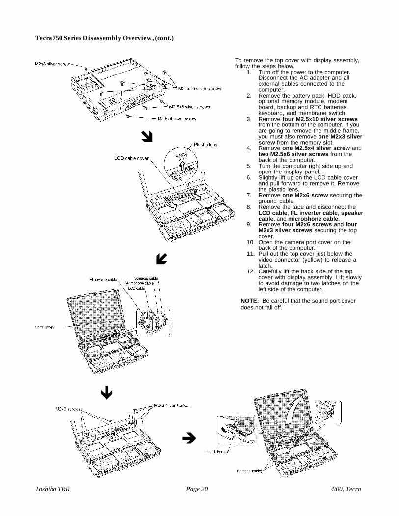
To remove the top cover with display assembly,follow the steps below.
1. Turn off the power to the computer.Disconnect the AC adapter and allexternal cables connected to thecomputer.
2. Remove the battery pack, HDD pack,optional memory module, modemboard, backup and RTC batteries,keyboard, and membrane switch.
3. Remove four M2.5x10 silver screwsfrom the bottom of the computer. If youare going to remove the middle frame,you must also remove one M2x3 silverscrew from the memory slot.
4. Remove one M2.5x4 silver screw andtwo M2.5x6 silver screws from theback of the computer.
5. Turn the computer right side up andopen the display panel.
6. Slightly lift up on the LCD cable coverand pull forward to remove it. Removethe plastic lens.
7. Remove one M2x6 screw securing theground cable.
8. Remove the tape and disconnect theLCD cable, FL inverter cable, speakercable, and microphone cable.
9. Remove four M2x6 screws and fourM2x3 silver screws securing the topcover.
10. Open the camera port cover on theback of the computer.
11. Pull out the top cover just below thevideo connector (yellow) to release alatch.
12. Carefully lift the back side of the topcover with display assembly. Lift slowlyto avoid damage to two latches on theleft side of the computer.
NOTE: Be careful that the sound port coverdoes not fall off.
î
ê
è
í

Toshiba TRR 4/00, TecraPage 21
Tecra 750 Series Disassembly Overview, (cont.)
To remove the speakers, follow the steps below.1. Turn off the power to the computer.
Disconnect the AC adapter and allexternal cables connected to thecomputer.
2. Remove the battery pack, HDD pack,optional memory module, modemboard, backup and RTC batteries,keyboard, membrane switch, and topcover with display assembly.
3. Remove four M2x4 silver screwssecuring the speaker holders.
4. Lift out the speakers with cables andholders.
5. Pull the speakers out of the holders.6. Remove the tape securing the cables to
the insulator and remove the speakers.
NOTE: The speaker wire is color coded. Notehow the cables are routed.
To remove the system board, follow the stepsbelow.
1. Turn off the power to the computer.Disconnect the AC adapter and allexternal cables connected to thecomputer.
2. Remove the battery pack, HDD pack,optional memory module, modemboard, backup and RTC batteries,keyboard, membrane switch, and topcover with display assembly.
3. Remove three M2.5x4 screwssecuring the metal frame and removeit.
4. Remove the audio connectors cover.5. Remove two M2.5x8 screws, and one
M2x4 silver screw securing the shieldplate to the system board.
6. Remove two stud screws and oneM2.5x4 screw securing the systemboard to the middle frame.
7. Remove one M2x3 silver screwsecuring the positioning plate and liftout the plate. A tongue on the plate fitsinto a notch.
8. Open the USB port cover and removeone M2x4 silver screw securing theUSB port to the USB connector.
9. Pull the metal cover protecting the S-video and PS/2 ports away from theports, so it doesn’t catch on them whenyou lift up the board.
10. Lift up the system board to disconnecttwo connectors.
ê
î

4/00, TecraToshiba TRR Page 22
Tecra 750 Series Disassembly Overview, (cont.)
To remove the fan, follow the steps below.1. Turn off the power to the computer.
Disconnect the AC adapter and allexternal cables connected to thecomputer.
2. Remove the battery pack, HDD pack,optional memory module, modemboard, backup and RTC batteries,keyboard, membrane switch, top coverwith display assembly, and systemboard.
3. Turn the system board upside downand remove the tape securing the fancable.
4. Disconnect the fan cable from PJ550on the system board.
5. Turn the system board right side up andremove two M2.5x4 screws.
6. Lift out the fan.
To remove the middle frame, follow the stepsbelow.
1. Turn off the power to the computer.Disconnect the AC adapter and allexternal cables connected to thecomputer.
2. Remove the battery pack, HDD pack,optional memory module, modemboard, backup and RTC batteries,keyboard, membrane switch, top coverwith display assembly, and systemboard.
3. Remove two M2.5x4 screws and oneM2.5x8 screw securing the SelectableBay top cover to the middle frame.
4. Two positioning pins fit into holes onthe Selectable Bay top cover. Pry thecover free of the pins then lift off thecover.
5. Disconnect two secondary batterycables from the I/O board.
6. Remove six M2.5x8 screws and oneM2.5x4 screw securing the middleframe to the bottom cover.
7. Pull out the Selectable Bay releaselever and set the Selectable Bay lockto the lock position.
CAUTION: If you remove the middle framewhile the Selectable Bay lock is unlocked, theI/O board will be damaged.
NOTE: Make sure the screw in the memoryslot has been removed.
8. Lift off the PC card slot cover and liftout the middle frame.
9. Remove one M2x3 screw securing thebracket over the probe pin harness.
10. Remove two M2x5 screws securing theprobe pin harness to the middle frame.
11. Lift out the probe pin harness and notehow the cables are threaded.
ê

Toshiba TRR 4/00, TecraPage 23
Tecra 750 Series Disassembly Overview, (cont.)
To install the middle frame, follow the stepsbelow.
1. Reroute the cables and replace theprobe pin harness.
2. Secure the probe pin harness to themiddle frame with two M2x5 screws.
3. Secure the bracket over the probe pinharness with one M2x3 screw.
4. Make sure the Selectable Bay releaselever is extended and the SelectableBay lock is in the lock position.
5. Seat the middle frame and make sure asmall tongue on the middle frame’sSelectable Bay locking mechanism fitsinto a corresponding notch on theexternal Selectable Bay lock.
6. Secure one M2.5x8 screw next to theSelectable Bay lock arm, then securethe other five M2.5x8 screws.
7. Secure the middle frame to the bottomcover with one M2.5x4 screw.
8. Seat the PC card slot cover.9. Secure the Selectable Bay top cover
with two M2.5x4 screws and oneM2.5x8 screw.
10. Connect two secondary battery cablesto the I/O board.
11. Install the battery pack, HDD pack,optional memory module, modemboard, backup and RTC batteries,keyboard, membrane switch, top coverwith display assembly, and systemboard.
5. Lift out the I/O board.6. Lift out the base shield assembly.
4. Remove one M2x6 screw securing theI/O board to the bottom cover.
To remove the I/O board, follow the steps below.1. Turn off the power to the computer.
Disconnect the AC adapter and allexternal cables connected to thecomputer.
2. Remove the battery pack, HDD pack,optional memory module, modemboard, backup and RTC batteries,keyboard, membrane switch, top coverwith display assembly, system board,and middle frame.
3. Remove the battery pack jumper asfollows:
(a) From the bottom of the batterypack slot, push up on thebattery jumper contact andslide it forward.
(b) Press down on the jumper asshown in the Figure below andslide the jumper out to removeit.
î
4/00, TecraToshiba TRR Page 24
Tecra 750 Series Disassembly Overview, (cont.)
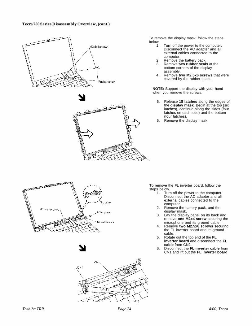
To remove the display mask, follow the stepsbelow.
1. Turn off the power to the computer.Disconnect the AC adapter and allexternal cables connected to thecomputer.
2. Remove the battery pack.3. Remove two rubber seals at the
bottom corners of the displayassembly.
4. Remove two M2.5x6 screws that werecovered by the rubber seals.
NOTE: Support the display with your handwhen you remove the screws.
5. Release 18 latches along the edges ofthe display mask. Begin at the top (sixlatches), continue along the sides (fourlatches on each side) and the bottom(four latches).
6. Remove the display mask.
î
To remove the FL inverter board, follow thesteps below.
1. Turn off the power to the computer.Disconnect the AC adapter and allexternal cables connected to thecomputer.
2. Remove the battery pack, and thedisplay mask.
3. Lay the display panel on its back andremove one M2x4 screw securing themicrophone and its ground cable.
4. Remove two M2.5x6 screws securingthe FL inverter board and its groundcable.
5. Rotate out the top end of the FLinverter board and disconnect the FLcable from CN2.
6. Disconnect the FL inverter cable fromCN1 and lift out the FL inverter board.î
Toshiba TRR 4/00, TecraPage 25
Tecra 750 Series Disassembly Overview, (cont.)
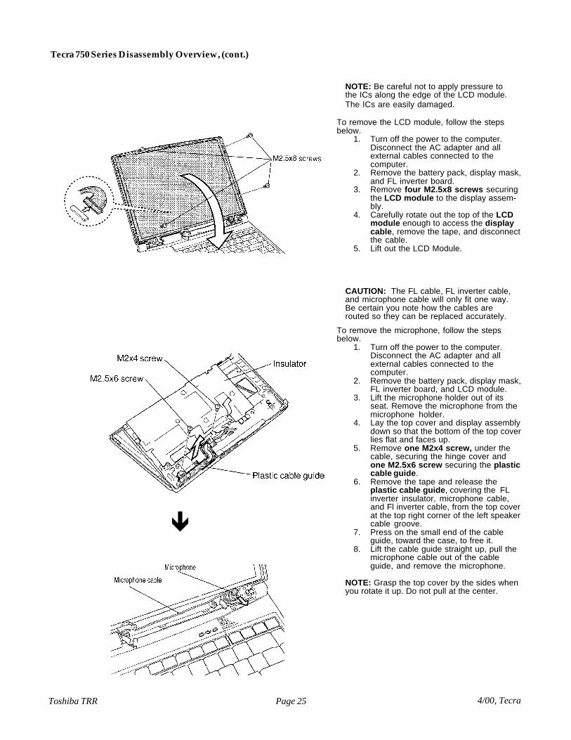
NOTE: Be careful not to apply pressure tothe ICs along the edge of the LCD module.The ICs are easily damaged.
To remove the LCD module, follow the stepsbelow.
1. Turn off the power to the computer.Disconnect the AC adapter and allexternal cables connected to thecomputer.
2. Remove the battery pack, display mask,and FL inverter board.
3. Remove four M2.5x8 screws securingthe LCD module to the display assem-bly.
4. Carefully rotate out the top of the LCDmodule enough to access the displaycable, remove the tape, and disconnectthe cable.
5. Lift out the LCD Module.
CAUTION: The FL cable, FL inverter cable,and microphone cable will only fit one way.Be certain you note how the cables arerouted so they can be replaced accurately.
To remove the microphone, follow the stepsbelow.
1. Turn off the power to the computer.Disconnect the AC adapter and allexternal cables connected to thecomputer.
2. Remove the battery pack, display mask,FL inverter board, and LCD module.
3. Lift the microphone holder out of itsseat. Remove the microphone from themicrophone holder.
4. Lay the top cover and display assemblydown so that the bottom of the top coverlies flat and faces up.
5. Remove one M2x4 screw, under thecable, securing the hinge cover andone M2.5x6 screw securing the plasticcable guide.
6. Remove the tape and release theplastic cable guide, covering the FLinverter insulator, microphone cable,and Fl inverter cable, from the top coverat the top right corner of the left speakercable groove.
7. Press on the small end of the cableguide, toward the case, to free it.
8. Lift the cable guide straight up, pull themicrophone cable out of the cableguide, and remove the microphone.
NOTE: Grasp the top cover by the sides whenyou rotate it up. Do not pull at the center.
ê
4/00, TecraToshiba TRR Page 26
Tecra 750 Series Disassembly Overview, (cont.)
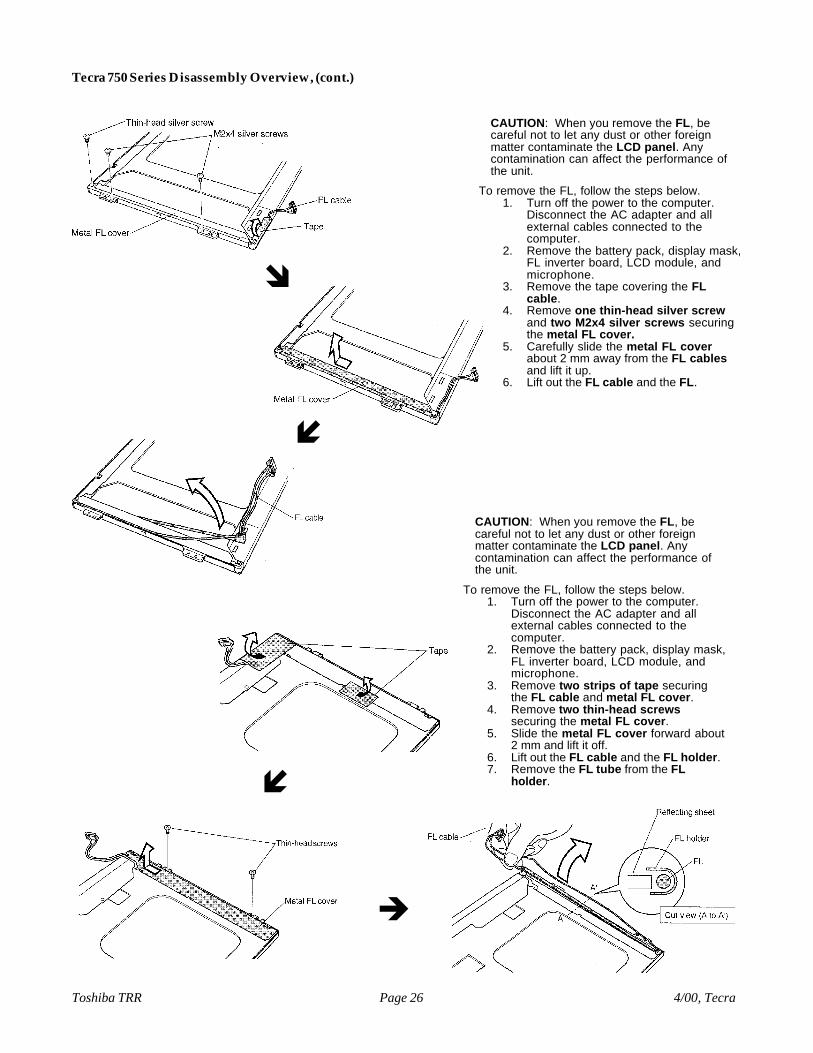
CAUTION: When you remove the FL, becareful not to let any dust or other foreignmatter contaminate the LCD panel. Anycontamination can affect the performance ofthe unit.
To remove the FL, follow the steps below.1. Turn off the power to the computer.
Disconnect the AC adapter and allexternal cables connected to thecomputer.
2. Remove the battery pack, display mask,FL inverter board, LCD module, andmicrophone.
3. Remove the tape covering the FLcable.
4. Remove one thin-head silver screwand two M2x4 silver screws securingthe metal FL cover.
5. Carefully slide the metal FL coverabout 2 mm away from the FL cablesand lift it up.
6. Lift out the FL cable and the FL.
î
í
CAUTION: When you remove the FL, becareful not to let any dust or other foreignmatter contaminate the LCD panel. Anycontamination can affect the performance ofthe unit.
To remove the FL, follow the steps below.1. Turn off the power to the computer.
Disconnect the AC adapter and allexternal cables connected to thecomputer.
2. Remove the battery pack, display mask,FL inverter board, LCD module, andmicrophone.
3. Remove two strips of tape securingthe FL cable and metal FL cover.
4. Remove two thin-head screwssecuring the metal FL cover.
5. Slide the metal FL cover forward about2 mm and lift it off.
6. Lift out the FL cable and the FL holder.7. Remove the FL tube from the FL
holder.í
è

Toshiba TRR 4/00, TecraPage 27
Tecra 750 Series Disassembly Overview, (cont.)
CAUTION: When you remove the FL, becareful not to let any dust or other foreignmatter contaminate the LCD panel. Anycontamination can affect the performance ofthe unit.
To remove the FL, follow the steps below.1. Turn off the power to the computer.
Disconnect the AC adapter and allexternal cables connected to thecomputer.
2. Remove the battery pack, display mask,FL inverter board, LCD module, andmicrophone.
3. Remove one strip of tape securing theFL cable to the LCD frame and lift the FLcable.
4. Remove two M2x4 thin-head silverscrews, one M2x1 thin-head blackscrew, and four thin-head silverscrews.
5. Carefully peel up the insulator adheredto the circuit boards and ICs.
6. Disconnect the flexible cable from thelarger board and press down theconnector flap to avoid damage.
7. Lift up the center of the metal FL coveruntil two latches are released.
8. Insert a thin object such as the end oftweezers under the metal FL cover untilthe cover is freed.
9. Lift up on the metal projections and pullthe FL cover slightly forward, slide it left,and lift it out.
10. Carefully lift up the white sheet coveringthe FL.
11. Lift out the pink FL cable connector.12. Lift the white FL cable out of its groove
to remove the FL with cables.
î
ê
í
Images continued on the next pageî

4/00, TecraToshiba TRR Page 28
Tecra 750 Series Disassembly Overview, (cont.)
ê
Removing the FL, continued.