tekmar 314 tn2 wiring center - four zone pumps
TRANSCRIPT
8/8/2019 Tekmar 314 tN2 Wiring Center - Four Zone Pumps
http://slidepdf.com/reader/full/tekmar-314-tn2-wiring-center-four-zone-pumps 1/8
D31410/09tN2 Wiring Center 314
1 of 8 © 2009 D 314 - 10/09
Power
Zone 1
Zone 2
Zone 3
Zone 4
End Switch
Zone 1 Zone 2 Zone 3 Zone 4
tN2 tN2 tN2 tN2 tN2 tN2 tN2 tN2
tN2 Wiring Center 314F o u r Z o n e P u m p s
t N 4
C
X
E x p a n s i o n
X
C
I n p u t P o w e r
R
Meets Class B: ICES & FCC Part 15
H8004A
E n d S w i t c h
Use at least 167°F (75°C) conductors
Input Power: 24 V (ac) ±10% 60 Hz
Class 2Control Load: 11 VAEnd Switch: 24 V (ac) 2 APump Relays: 115 V (ac) 5 AZone Power: 115 V (ac) 12 A
Made in Canadatektra 1034-02
For use with tN2 thermostats only
tN2
Power
Zone 1
Zone 2
Zone 3
Zone 4
End Switch
tN2 Wiring Center 314F o u r Z o n e P u m p s
Input Power: 24 V (ac) ±10% 60 Hz
Class 2Control Load: 11VAEnd Switch: 24 V (ac) 2 APump Relays: 115 V (ac) 5 AZone Power: 115 V (ac) 12 A
Made in Canadatektra 1034-02
tN2
Introduction
Table of Contents
Control Location .............................................................2
Mounting the Control ......................................................2
Sizing the Transformer ...................................................2
Wiring the Control ...........................................................3
Sequence of Operation ...................................................3
Application Drawings ...................................................4-5
Troubleshooting Guide.................................................6-7
Technical Data ................................................................8
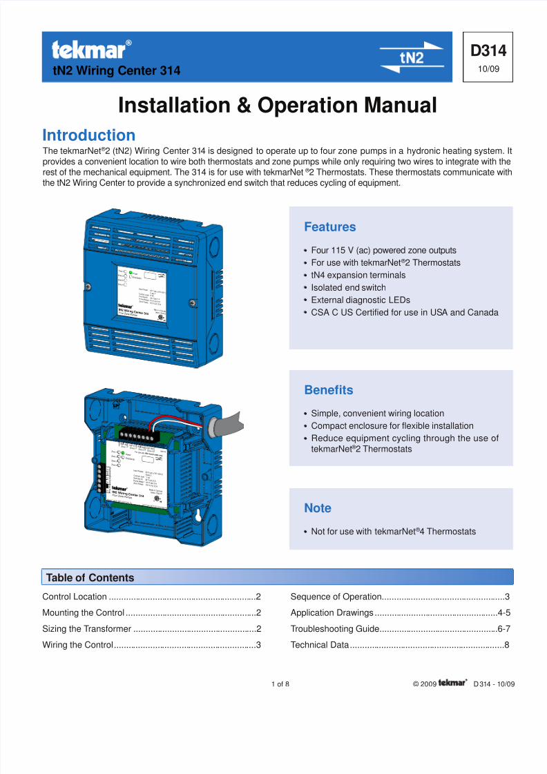
The tekmarNet ® 2 (tN2) Wiring Center 314 is designed to operate up to four zone pumps in a hydronic heating system. I
provides a convenient location to wire both thermostats and zone pumps while only requiring two wires to integrate with therest of the mechanical equipment. The 314 is for use with tekmarNet ® 2 Thermostats. These thermostats communicate withthe tN2 Wiring Center to provide a synchronized end switch that reduces cycling of equipment.
Features
•• Four 115 V (ac) powered zone outputs
•• For use with tekmarNet ® 2 Thermostats
•• tN4 expansion terminals
•• Isolated end switch
•• External diagnostic LEDs
•• CSA C US Certified for use in USA and Canada
Installation & Operation Manual
Benefits
•• Simple, convenient wiring location
•• Compact enclosure for flexible installation
•• Reduce equipment cycling through the use of
tekmarNet ® 2 Thermostats
Note
•• Not for use with tekmarNet ® 4 Thermostats

8/8/2019 Tekmar 314 tN2 Wiring Center - Four Zone Pumps
http://slidepdf.com/reader/full/tekmar-314-tn2-wiring-center-four-zone-pumps 2/8
© 2009 D 314 - 10/09 2 of 8
Mounting the Control
•• Remove the front cover of the Wiring Center by removingthe two screws in the cover.
•• There are four holes in the back of the enclosure thatallow for mounting to a 4”x4” electrical box.
•• The conduit knockouts provided on the sides of the Wiring
Center can be used to neatly route wiring to and fromthe control. Wiring can also enter through the top of theenclosure.
•• Zone pump connections are located at the back and willbe placed inside the 4”x4” electrical box.
Note: The nonmetallic conduit entries on the sides ofthe enclosure do not provide grounding between conduit
connections. Use bonding bushings and jumpers to providea continuous path to ground.
Caution
Improper installation and operation of this control could resultin damage to the equipment and possibly even personal
injury or death. It is your responsibility to ensure that thiscontrol is safely installed according to all applicable codes
and standards. This electronic control is not intended for
uses as a primary limit control. Other controls that are
intended and certified as safety limits must be placed into
the control circuit. Do not attempt to service the control.Refer to qualified personnel for servicing. There are nouser serviceable parts. Attempting to do so voids warranty
and could result in damage to the equipment and possiblyeven personal injury or death.
Sizing the Transformer
The 314 requires an external transformer. A tekmarTransformer 009 (or 009K which includes a 4”x4” electricalbox) can supply up to 40 VA, and includes an in-line fuse
to protect the transformer.
In order to correctly size the external transformer, all loadsconnected to the control must be taken into account.
•• The Wiring Center 314 will draw approximately 3 VA
itself.•• tekmarNet ® 2 Thermostats draw about 2 VA each.
Note: The total power capacity of the power supply shouldbe larger than the total load of all the devices connectedto the tN2 Wiring Center. This total load must not exceed
98 VA.
The following chart is provided to simplify transformersizing:
Control LocationWhen choosing the location for the control, consider thefollowing:
•• Keep dry. Avoid potential leakage onto the control.RH 90 % in a non-condensing environment.
•• Do not expose to temperatures beyond 32 to 122°F
(0 to 50°C).
•• Provide adequate ventilation.
•• Keep away from equipment, appliances or other sourcesof electrical interference.
•• Locate the control near the zone valves and thermostats.
Zone Pump Output Wiring
Transformer
115 V (ac) Power Input
Zone 1 2 3 4
ThermostatLoad
ControlLoad (VA)
Total Zone Load + + + + 3
Transformermust exceed:
VA
8/8/2019 Tekmar 314 tN2 Wiring Center - Four Zone Pumps
http://slidepdf.com/reader/full/tekmar-314-tn2-wiring-center-four-zone-pumps 3/8
3 of 8 © 2009 D 314 - 10/09
Electrical Drawings
Sequence of Operation
•• When a thermostat calls for heat, it sends a messageto the Wiring Center and the corresponding zone LED
turns on. Power is then supplied to the appropriate zoneoutput as indicated by the LED.
•• The end switch relay (‘XX’) closes and the end switch
LED turns on. The switch remains closed as long as anyzone is calling for heat. This can provide a boiler demandto a reset module such as a tekmar Boiler Control 260.
Synchronized End Switch
Using tekmarNet ® 2 Thermostats, the Wiring Center hasa synchronized end switch feature. This ‘synchronizesthe start times of zones and reduces short cycling o
equipment connected to the Wiring Center’s end switchThe net effect is increased system efficiency and reduced
wear on equipment.
•• If the Wiring Center is connected to a tN4 bus, alcommunication messages will pass through the 314’s
tN4 expansion connection. tN4 messages are requiredin order to create a boiler demand on a device such as
a tekmar Boiler Reset Module 420.
Wiring the Control
External Power Supply
It is strongly recommended that a transformer with an in-
line fuse be used in order to protect the control and thetransformer from high currents. The tekmar Transformer 009includes a fuse. Once the transformer has been correctlysized as described on page 2, connect the 24 V (ac) leads
from the transformer to the R and C terminals marked “InputPower” on the Wiring Center.
tekmarNet ® 2 Thermostats
The tN2 Wiring Center 314 is designed to operate withtekmarNet ® 2 Thermostats. They provide a synchronized
end switch on the Wiring Center and communicate withany other tN2 device on the system.
•• Connect the tN2 terminals from each thermostat to thecorresponding terminals for each zone on the WiringCenter.
Zone Pumps
•• Connect line voltage to the red zone power lead in ordeto supply the required power to the zone pumps.
•• Connect one side of the zone pump to the black zone
pump output wires on the back of the 314. This outpuwill become energized when the zone calls for heat.
• Connect the other side of the pump to the neutral line onthe same circuit as the zone power input.
tN4 Expansion
The Wiring Center acts as a link between tekmarNet ® 2Thermostats and other tN4 devices, such as a tN4 Boiler
Control, Zone Manager or Reset Module. It can also beused to add more zones to a tN2 House Control System
•• Connect the tN4 and C expansion terminals to thecorresponding terminals on the external tN4 device.
End Switch
The tN2 Wiring Center 314 can be used to provide a calfor heat to an external device without tN4 connections
The end switch is an isolated dry contact relay rated fo2A at 24 V (ac).
The electrical drawing examples on the following pages
show the 314 in common applications. These drawingshave a brief explanation of what is being operated in each
system. Choose the components in your system and usethe drawings as a guide to aid in wiring your system.
These are only concept drawings, not engineered drawings.They are not intended to describe a complete system nor
any particular system. It is up to the system designer to
determine the necessary components for and configuration
of the particular system being designed including additionaequipment isolation relays (for loads greater than the
controls specified output ratings) and any safety deviceswhich in the judgement of the designer are appropriate in
order to properly size, configure and design that systemand to ensure compliance with building and safety coderequirements.
8/8/2019 Tekmar 314 tN2 Wiring Center - Four Zone Pumps
http://slidepdf.com/reader/full/tekmar-314-tn2-wiring-center-four-zone-pumps 4/8
© 2009 D 314 - 10/09 4 of 8
Application Drawing 314 A1
tekmar 009
Transformer
24 V (ac)
CC
RR
External
tN4Connection
(ie: House Controlor Zone Manager)
tN4
C
Directly Enabled
Boiler Control
TT
TT
F u s e
Maximum Zone Power Input 115V, 12A
Pump
115 V (ac)LNG
Pump Pump Pump
OR
tN2 tN2
tN2Thermostat
tN2 tN2
tN2Thermostat
tN2 tN2
tN2Thermostat
tN2 tN2
tN2Thermostat
L
N
PowerZone 1
Zone 2
Zone 3
Zone 4
End Switch
Zone 1 Zone 2 Zone 3 Zone 4tN2 tN2 tN2 tN2 tN2 tN2 tN2 tN2
tN2 Wiring Center 314Four Zone Pumps
t N 4
C
X
E x p a n s i o n
Vlv
X
C
I n p u t P o w e r
R
Meets Class B: ICES & FCC Part 15
H8004A
E n d S wi t c h
Use at least 167°F (75°C) conductors
Input Power: 24 V (ac) ±10% 60 HzClass 2
Control Load: 3 VAEnd Switch: 24 V (ac) 2 APump Relays: 115 V (ac) 5 AZone Power: 115 V (ac) 12 A
Made in Canadatektra 1034-02
For use with tN2 thermostats only
tN2
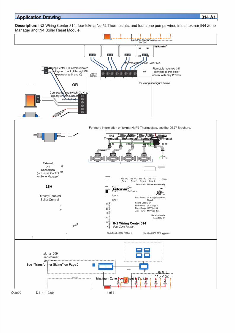
Description: tN2 Wiring Center 314, four tekmarNet ® 2 Thermostats, and four zone pumps wired into a tekmar tN4 Zone
Manager and tN4 Boiler Reset Module.
for wiring see figure below
314
See tN2 thermostatsection
thermostats on tN2 Boiler bus
tNt tNt
tNt tNt
Remotely mounted 314connects to tN4 boiler
control with only 2 wires
Wiring Center 314 communicates
to tN4 system control through tN4
expansion (tN4 and C)
Connect the end switch (X, X) to
directly enable a boiler control
(see below)
OR
OutdoorSensor
See “Transformer Sizing” on Page 2
For more information on tekmarNet ® 2 Thermostats, see the D527 Brochure.
8/8/2019 Tekmar 314 tN2 Wiring Center - Four Zone Pumps
http://slidepdf.com/reader/full/tekmar-314-tn2-wiring-center-four-zone-pumps 5/8
5 of 8 © 2009 D 314 - 10/09
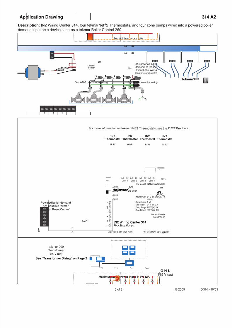
Application Drawing 314 A2
Description: tN2 Wiring Center 314, four tekmarNet ® 2 Thermostats, and four zone pumps wired into a powered boiler
demand input on a device such as a tekmar Boiler Control 260.
Maximum Zone Power Input 115V, 12A
Pump
115 V (ac)LNG
Pump Pump Pump
Powered boiler demand(ie: input into tekmar
Outdoor Reset Control)
tekmar 009
Transformer
24 V (ac)
CC
RR
F u s e
tN2 tN2
tN2Thermostat
tN2 tN2
tN2Thermostat
tN2 tN2
tN2Thermostat
tN2 tN2
tN2Thermostat
L
N
PowerZone 1
Zone 2
Zone 3
Zone 4
End Switch
Zone 1 Zone 2 Zone 3 Zone 4tN2 tN2 tN2 tN2 tN2 tN2 tN2 tN2
tN2 Wiring Center 314Four Zone Pumps
t N 4
C
X
E x p a n s i o n
Vlv
X
C
I n p u t P o w e r
R
Meets Class B: ICES & FCC Part 15
H8004A
E n d S wi t c h
Use at least 167°F (75°C) conductors
Input Power: 24 V (ac) ±10% 60 HzClass 2
Control Load: 3 VAEnd Switch: 24 V (ac) 2 APump Relays: 115 V (ac) 5 AZone Power: 115 V (ac) 12 A
Made in Canadatektra 1034-02
For use with tN2 thermostats only
tN2
See figure below for wiringSee A260 brochure for wiring
314
See tN2 thermostat section
tNt tNt
tNt tNt
314 provides ‘boilerdemand’ to the 260
through the WiringCenter’s end switch
OutdoorSensor
260
See “Transformer Sizing” on Page 2
For more information on tekmarNet ® 2 Thermostats, see the D527 Brochure.

8/8/2019 Tekmar 314 tN2 Wiring Center - Four Zone Pumps
http://slidepdf.com/reader/full/tekmar-314-tn2-wiring-center-four-zone-pumps 6/8
© 2009 D 314 - 10/09 6 of 8
General
The following tests are to be performed using standardtesting practices and procedures and should only be carriedout by properly trained and experienced persons.
A good quality electrical test meter, capable of readingfrom at least 0-300 V (ac), 0-300 V (dc), 0-2,000,000
Ohms, and testing for continuity is essential to properlytest the wiring.
Test Meter
### Control Terminals
Testing the Input Power
1. Remove the front cover from the control.
2. Use an electrical test meter to measure (ac) voltagebetween the input power R and C terminals. The reading
should be 24 V (ac) + / – 10% and the power LED shouldbe lit green.
3. If power is not present and the light is off:
•• Check the circuit that supplies power to the tN2 WiringCenter.
4. If the transformer is being powered with line voltage and
the power LED is not lit:
•• If using the tekmar Transformer 009 check the fieldreplaceable transformer fuse in line with the 24 V (ac)output of the 009.
•• If the fuse is blown, determine the cause of the failurebefore replacing the fuse.
•• If a transformer other than the tekmar 009 is used then
a fuse may not be present. Verify that the transformer isbeing fed the proper voltage. If the input voltage is correct,
and there is no output voltage, then the transformer islikely damaged and should be replaced. Find the cause
of the overload before replacing the transformer. Ensuretransformer is sized for the entire load (See “TransformerSizing” on Page 2).
Testing the Thermostat Wires
tekmarNet ® 2 Thermostats
To test the tekmarNet ® 2 Thermostats, check the wires forcontinuity and shorts.
1. Disconnect the two tN2 wires at one end and twist themtogether.
2. Go to the other end of the wires and disconnect them.
3. Using an electrical test meter, check for continuity.Resistance should read 0 ohms, or continuity should
produce a tone. If not, this indicates that there aredamaged wires connecting the thermostat to the 314.Repair or replace them as necessary.
4. Go back to the original end of the wires and, using awire nut, cap each tN2 wire individually so that theseends cannot touch another conductor.
5. Go to the other end of the wires and again, test for shorts.Resistance should be infinite, or O.L. and there should
be no tone. If tone exists or less than 50 000 ohms isfound, then the wires are not insulated from one another.
This is generating a short on the wires connecting thethermostats to the 314.
6. Replace the damaged wires, test, and reconnect themto their proper terminals.
We expect your tekmarNet ® system to operate trouble-free. If an error should occur, simply follow these steps:
1. Find: If a tekmarNet ® Thermostat flashes on the bottom of the screen, it is indicating a problem on the system.
2. Identify: Match what is showing on the thermostat screen with one of the error messages shown in its manual.
3. Solve: The error could be a result of improper wiring at the Wiring Center. Follow the tests below for testing stepsand solutions.
The following information, in addition to any error messages found on a tekmarNet ®
system, can be used tolocate problems in the system. Please refer to the thermostat manual for error code information.
Troubleshooting Guide

8/8/2019 Tekmar 314 tN2 Wiring Center - Four Zone Pumps
http://slidepdf.com/reader/full/tekmar-314-tn2-wiring-center-four-zone-pumps 7/8
7 of 8 © 2009 D 314 - 10/09
Testing the tN4 Network
To test the tN4 Network, check the wires for continuityand shorts.
1. Disconnect the two tN4 expansion wires (tN4 and C) atone end and twist them together.
2. Go to the other end of the wires and disconnect them.
3. Using an electrical test meter, check for continuity.Resistance should read 0 ohms, or continuity should
produce a tone. If not, this indicates that there aredamaged wires connecting the tN4 control to the 314.Repair or replace them as necessary.
4. Go back to the original end of the wires and, using a
wire nut, cap each expansion wire individually so thathese ends cannot touch another conductor.
5. Go to the other end of the wires and again, test for shorts
Resistance should be infinite, or O.L. and there should
be no tone. If tone exists or less than 50 000 ohms isfound, then the wires are not insulated from one another
This is generating a short on the wires connecting thetN4 control to the 314.
6. Replace the damaged wires, test, and reconnect them
to their proper terminals.
Testing the Zone Pump Outputs
Testing the End Switch
If the tN4 expansion is not used to connect the tN2 WiringCenter to the system, the end switch may be used.
1. Remove the wires from the end switch terminals.
2. Use an electrical test meter to measure continuity acrossthe XX end switch terminals on the 314.
•• When the end switch LED is off, no continuity should bepresent (no tone).
•• When the end switch LED is on, continuity should bepresent (tone).
1. Using an electrical meter, test the voltage across thepump terminals on the zone pump:
• When the zone LED is off, the reading should be 0 V(ac) and the pump should be off.
• When the zone LED is on, the reading should be 115 V(ac) + / – 10% and the pump should be running.
• If voltage is present at the pump when the zone LEDis on, this indicates a fault with the pump. Refer totroubleshooting information supplied by the pumpmanufacturer.
If the voltage is not present when the zone LED is on:
1. Turn off power to the control and zone power Input.
2. Remove the front cover from the control.
3. Remove the Wiring Center from the junction box toaccess the zone pump wires on the rear of the control.
4. Remove wire nut from zone power and cap 115 V (acline voltage input wire with a wire nut for safety, thenpower the control back up.
5. Use an electrical test meter to check for continuitybetween the zone power input and each zone pumpoutput.
• When the zone LED is off, the resistance should beinfinite or O.L. and there should be no tone.
• When the zone LED is on, the resistance should be 0ohms, or continuity should produce a tone.
6. If the control passes the continuity test, this indicates afault in the wiring between the control and the pumpsReplace damaged or shorted wires, test, and reconnecthem to their proper terminals.
Testing the tN2 Thermostat Connection Terminals 5 - 12
If the thermostat display turns on this indicates that thethermostat is operating correctly and there are no electrical
issues.
In the event that a thermostat display does not turn on:
1. Remove the tN2 wires from the affected zone on the314.
2. Use an electrical test meter to measure DC voltagebetween the tN2 terminals on the 314 for 20 seconds.
• If the DC voltage is 0 V (dc) for 10 seconds and then is
23 to 24 V (dc) for 5 seconds, this indicates the 314 isoperating correctly.
• If the DC voltage remains at 0 V (dc) on the 314 for 20seconds, there may be a fault on the 314. Contact you
local tekmar sales representative for assistance.
8/8/2019 Tekmar 314 tN2 Wiring Center - Four Zone Pumps
http://slidepdf.com/reader/full/tekmar-314-tn2-wiring-center-four-zone-pumps 8/8
Product design, software and literature are Copyright © 2009 by:tekmar Control Systems Ltd. and tekmar Control Systems, Inc. 8 of 8 All specifications are subject to change without notice.Printed in Canada. D 314 - 10/09.
tekmar Control Systems Ltd., Canada, tekmar Control Systems, Inc., U.S.A.Head Office: 5100 Silver Star Road, Vernon, B.C. Canada V1B 3K4, 250-545-7749, Fax. 250-545-0650 Web Site: www.tekmarcontrols.com
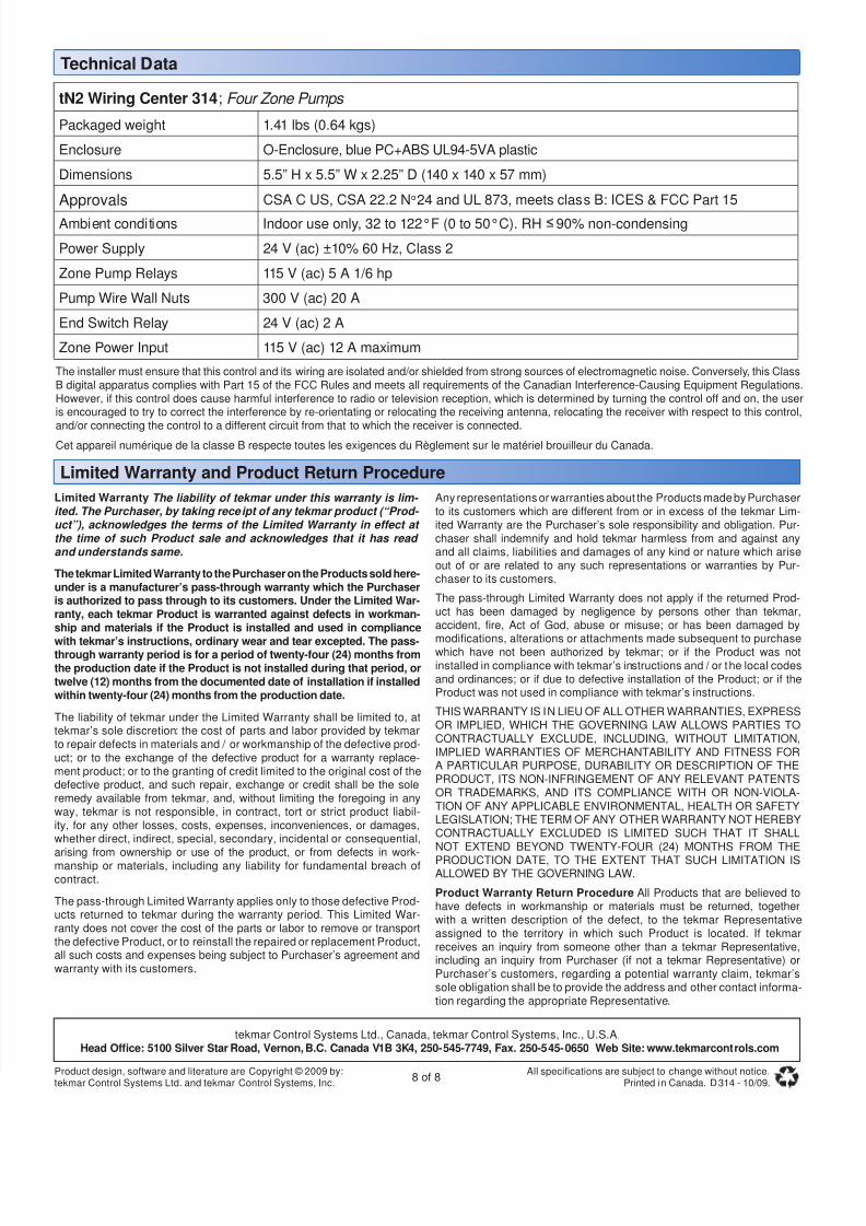
tN2 Wiring Center 314; Four Zone Pumps
Packaged weight 1.41 lbs (0.64 kgs)
Enclosure O-Enclosure, blue PC+ABS UL94-5VA plastic
Dimensions 5.5” H x 5.5” W x 2.25” D (140 x 140 x 57 mm)
Approvals CSA C US, CSA 22.2 No24 and UL 873, meets class B: ICES & FCC Part 15
Ambient conditions Indoor use only, 32 to 122°F (0 to 50°C). RH 90% non-condensing
Power Supply 24 V (ac) ±10% 60 Hz, Class 2
Zone Pump Relays 115 V (ac) 5 A 1/6 hp
Pump Wire Wall Nuts 300 V (ac) 20 A
End Switch Relay 24 V (ac) 2 A
Zone Power Input 115 V (ac) 12 A maximum
Technical Data
The installer must ensure that this control and its wiring are isolated and/or shielded from strong sources of electromagnetic noise. Conversely, this ClassB digital apparatus complies with Part 15 of the FCC Rules and meets all requirements of the Canadian Interference-Causing Equipment Regulations.However, if this control does cause harmful interference to radio or television reception, which is determined by turning the control off and on, the useris encouraged to try to correct the interference by re-orientating or relocating the receiving antenna, relocating the receiver with respect to this control,
and/or connecting the control to a different circuit from that to which the receiver is connected.Cet appareil numérique de la classe B respecte toutes les exigences du Règlement sur le matériel brouilleur du Canada.
Limited Warranty The liability of tekmar under this warranty is lim- ited. The Purchaser, by taking receipt of any tekmar product (“Prod- uct”), acknowledges the terms of the Limited Warranty in effect at the time of such Product sale and acknowledges that it has read and understands same.
The tekmar Limited Warranty to the Purchaser on the Products sold here-under is a manufacturer’s pass-through warranty which the Purchaseris authorized to pass through to its customers. Under the Limited War-ranty, each tekmar Product is warranted against defects in workman-ship and materials if the Product is installed and used in compliance
with tekmar’s instructions, ordinary wear and tear excepted. The pass-through warranty period is for a period of twenty-four (24) months fromthe production date if the Product is not installed during that period, ortwelve (12) months from the documented date of installation if installedwithin twenty-four (24) months from the production date.
The liability of tekmar under the Limited Warranty shall be limited to, attekmar’s sole discretion: the cost of parts and labor provided by tekmarto repair defects in materials and / or workmanship of the defective prod-uct; or to the exchange of the defective product for a warranty replace-ment product; or to the granting of credit limited to the original cost of thedefective product, and such repair, exchange or credit shall be the soleremedy available from tekmar, and, without limiting the foregoing in anyway, tekmar is not responsible, in contract, tort or strict product liabil-ity, for any other losses, costs, expenses, inconveniences, or damages,whether direct, indirect, special, secondary, incidental or consequential,arising from ownership or use of the product, or from defects in work-manship or materials, including any liability for fundamental breach ofcontract.
The pass-through Limited Warranty applies only to those defective Prod-ucts returned to tekmar during the warranty period. This Limited War-ranty does not cover the cost of the parts or labor to remove or transportthe defective Product, or to reinstall the repaired or replacement Product,all such costs and expenses being subject to Purchaser’s agreement andwarranty with its customers.
Any representations or warranties about the Products made by Purchaserto its customers which are different from or in excess of the tekmar Lim-ited Warranty are the Purchaser’s sole responsibility and obligation. Pur-chaser shall indemnify and hold tekmar harmless from and against anyand all claims, liabilities and damages of any kind or nature which ariseout of or are related to any such representations or warranties by Pur-chaser to its customers.
The pass-through Limited Warranty does not apply if the returned Prod-uct has been damaged by negligence by persons other than tekmar,accident, fire, Act of God, abuse or misuse; or has been damaged by
modifications, alterations or attachments made subsequent to purchasewhich have not been authorized by tekmar; or if the Product was notinstalled in compliance with tekmar’s instructions and / or the local codesand ordinances; or if due to defective installation of the Product; or if theProduct was not used in compliance with tekmar’s instructions.
THIS WARRANTY IS IN LIEU OF ALL OTHER WARRANTIES, EXPRESSOR IMPLIED, WHICH THE GOVERNING LAW ALLOWS PARTIES TOCONTRACTUALLY EXCLUDE, INCLUDING, WITHOUT LIMITATION,IMPLIED WARRANTIES OF MERCHANTABILITY AND FITNESS FORA PARTICULAR PURPOSE, DURABILITY OR DESCRIPTION OF THEPRODUCT, ITS NON-INFRINGEMENT OF ANY RELEVANT PATENTSOR TRADEMARKS, AND ITS COMPLIANCE WITH OR NON-VIOLA-TION OF ANY APPLICABLE ENVIRONMENTAL, HEALTH OR SAFETYLEGISLATION; THE TERM OF ANY OTHER WARRANTY NOT HEREBYCONTRACTUALLY EXCLUDED IS LIMITED SUCH THAT IT SHALLNOT EXTEND BEYOND TWENTY-FOUR (24) MONTHS FROM THE
PRODUCTION DATE, TO THE EXTENT THAT SUCH LIMITATION ISALLOWED BY THE GOVERNING LAW.
Product Warranty Return Procedure All Products that are believed tohave defects in workmanship or materials must be returned, togetherwith a written description of the defect, to the tekmar Representativeassigned to the territory in which such Product is located. If tekmarreceives an inquiry from someone other than a tekmar Representative,including an inquiry from Purchaser (if not a tekmar Representative) orPurchaser’s customers, regarding a potential warranty claim, tekmar’ssole obligation shall be to provide the address and other contact informa-tion regarding the appropriate Representative.
Limited Warranty and Product Return Procedure