telecommunication signaling protocolswiki.bdnog.org/lib/exe/fetch.php/btrc2018/sip_ss7_bdnog.pdf ·...
TRANSCRIPT

Telecommunication Signaling Protocols
Prepared by:M Tanvir Siddique, PMP
Head of OperationsB-Trac Solutions LimitedCell: +8801730311601

Agenda
• SS7 Signaling• Short Message Service (SMS): Overview• SIP Signaling Basics• International Call Flow• Telecom Traffic Engineering
Signaling & Protocol : What it is
• Signaling is exchange of information between call components to provide & maintain telecommunication services. Signaling includes but not limited to:• Dialing digits• Ring back tone / Call waiting tone• IVR response• USSD
• Protocol is the means by which elements of telephone networks exchange information. Examples of protocols are:• SS7• SIP• H.323
SS7: What it is
• Signaling System 7 (SS7) is a signaling protocol which is speciallycharacterized by:• High Speed Packet Data• Out of Band Signaling
• SS7 carries messages between telecommunication nodes which carryinformation like• I’m forwarding a call to you originated from +8801730311601 and to be routed to+8801730311602. Look for it on Trunk 9235
• Someone Dialed +8801730311601, where do I route the call• The called subscriber +8801730311601 is busy, please release the call with a busytone
• The route to signaling point 9325 is congested. Please don’t route any call to thistrunk unless the call is above priority 2

Out of Band Signaling: What it is
• Signaling which takes a separate path than the one is used forconversation• Separate digital channel used for the purpose of signaling only• Signaling messages in between the conversations are beingtransmitted via the signaling channel without interrupting the voiceor data conversation• Also known as channel associated signaling

Out of Band Signaling: Benefits
• Allows transport of more data at a faster data rate (56 Kbps)• Allows signaling messages to be transmitted at any given point of thecall rather than at the beginning and at the end• Enables signaling between network elements which doesn’t havedirect trunk connections• SS7 signaling is critical to call processing, hence redundancy isensured during implementation of all elements

Signaling System: Essential Components
• Signal Switching Points (SSPs)qTelephone switches equipped with SS7 capable software & terminating signaling linksqResponsible for originate, terminate & switch calls
• Signal Transfer Points (STPs)qWork as packet switches of SS7 networksqReceives and routes incoming signaling messages towards proper destination qPerforms specialized routing functions
• Signal Control Points (SCPs)qDatabases providing information necessary for advanced call processing capabilities

Signaling System: Redundancy
• STP & SCP are usually deployed in pairs to ensure redundancy• Conventionally elements of a pair are not collocated to ensuregeographic redundancy• For convenience of network drawing, STP & SCP pairs are depicted asthe following symbols in the document
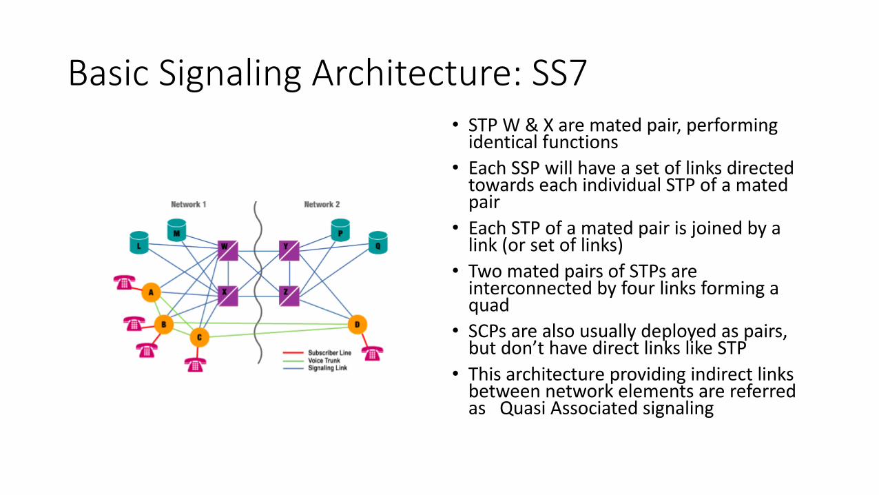
Basic Signaling Architecture: SS7• STP W & X are mated pair, performing
identical functions• Each SSP will have a set of links directed
towards each individual STP of a mated pair
• Each STP of a mated pair is joined by a link (or set of links)
• Two mated pairs of STPs are interconnected by four links forming a quad
• SCPs are also usually deployed as pairs, but don’t have direct links like STP
• This architecture providing indirect links between network elements are referred as Quasi Associated signaling

SS7 Link Types: Diagram

SS7 Link Types: Definition
A Links• A link, also referred to Access Link interconnects an STP with either an SSP or SCP
(i.e. either of the signaling end points)• Used for sole purpose of delivering signaling from signaling end points• Signaling to and from an SSP or SCP is routed via A link though its home STP
B or D Links• B links, also referred to as Bridge link establish signaling bridge between two STP• D links, also referred to as Diagonal links establish signaling connections between the
primary node of a mated pair of STP with the secondary node of a different STP pair• Responsibility is to carry signaling messages from the originating SSP or SCP to the
next layer of network nodes towards its destination

SS7 Links Type: Definition Contd.
C Links• C Links, also referred to as Cross Links interconnects the nodes of a mated pair of STP
between themselves• Purpose is to route the signaling message through its mated pair when it’s own B or
D link is Out of Service• Responsibility is to carry signaling messages from the originating SSP or SCP to the
next layer of network nodes towards its destination
E Links• E Links, also referred to as Extended Links creates a link between the SSP and a
second STP pair other than its own STP• Extended links are created to ensure the signaling communication is uninterrupted in
cases when both the STPs of home STP pair is Out of Service• E links are not mandatory links in a SS7 network and solely the discretion of the
network operator to decide based on cost benefit analysis

SS7 Links Type: Definition Contd.
F Links• F Links, also referred to as Fully Associated Links establishes direct signaling
connection between two SSP• Allow only associated signaling• Usually deployed between SSPs of an individual network not between cross
network as it bypasses all security features offered by STP

SS7: Basic Call Setup

SS7 Call Setup: Signaling Messages
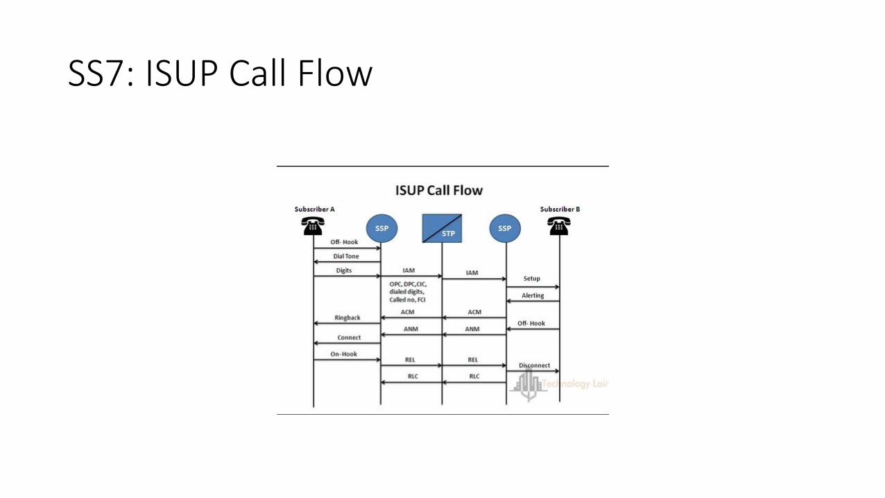
Initial Address Message (IAM)The basic message necessary to initiate a call. Basic information it carries include Initiating SSP, Destination SSP, Trunk selected, Calling Number, Called Number etc.
Address Complete Message (ACM)This is an acknowledgement confirming that the IAM has reached its proper destination. Information encapsulated in the message includes recipient SSP (A), sending SSP (B), Trunk number etc.

SS7 Call Setup: Signaling Messages Contd.
ANswer Message (ANM)SSP B formulates an ANM and sends to SSP A once the B party answers the call. ANM consists of information regarding recipient SSP (A), sending SSP (B) and trunk information
RELease Message (REL)Release message will be initiated by the SSP from which the subscriber first hang up. It will carry the information regarding the trunk
ReLease Complete (RLC)RLC is the acknowledgement message confirming the trunk being released which were communicated in the REL message

SS7: Basic Call Setup Steps
1. SSP A Analyzes the dialed digits to determine the call to be routed to SSP B
2. SSP A identifies a free trunk between A & B and sends an IAM
3. SSP A picks a A link to transmit the IAM to be routed to SSP B
4. STP W, upon receiving the message, inspect the routing label to route it to SSP B
5. SSP B analyzes the message upon receiving it and determines the subscriber is being served and idle
SS7: Basic Call Setup Steps Contd.
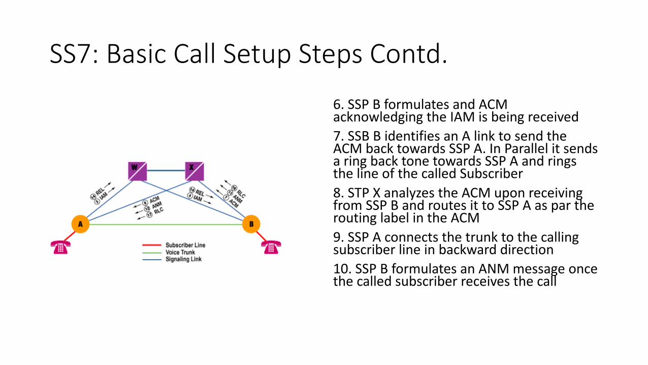
6. SSP B formulates and ACM acknowledging the IAM is being received 7. SSB B identifies an A link to send the ACM back towards SSP A. In Parallel it sends a ring back tone towards SSP A and rings the line of the called Subscriber8. STP X analyzes the ACM upon receiving from SSP B and routes it to SSP A as par the routing label in the ACM9. SSP A connects the trunk to the calling subscriber line in backward direction10. SSP B formulates an ANM message once the called subscriber receives the call

SS7: Basic Call Setup Steps Contd.
11. SSP B selects the same A Link to transmit the ANM after the called subscriber answered the call. At the same time the trunk must be connected to the called line in both direction12. STP X recognizes the ANM to be routed to SSP A from its routing label13. SSP A ensures that the calling subscriber is connected to the outgoing trunk to establish conversation14. REL messages will be initiated by the corresponding SSP of the subscriber who hang up first

SS7: Basic Call Setup Steps Contd.
15. Corresponding STP will receive the REL message and determines the destination SSP based on its routing label16. Receiving SSP of the REL messages disconnects the occupied trunk and sends a RLC message back to the originating SSP17. Corresponding STP analyzes the routing label upon receiving the RLC and routes it to the concerned SSP18. SSP release the occupied trunk from its side as well upon receiving the RLC

SS7 Protocol Stack

SS7: Protocol Stack Layers (MTP)
Message Transfer Part – Layer 1 (MTP 1)• Refers to the physical layer of SS7 signaling• Utilize DS-0 channels to carry raw signaling data• Data rate 56 kbps or 64 kbps
Message Transfer Part – Layer 2 (MTP 2)• Provides link layer functionality• Ensures two end points of the link can reliably exchange signaling• Incorporates capability of error checking, flow control, and sequence checking
Message Transfer Part – Layer 3 (MTP 3)• Provides network layer functionality• Ensures messages can be delivered over SS7 network irrespective of directly
connected SSPs • Includes capabilities as node addressing, routing, alternate routing, and congestion
control
SS7: Protocol Stack Layer (UAP)
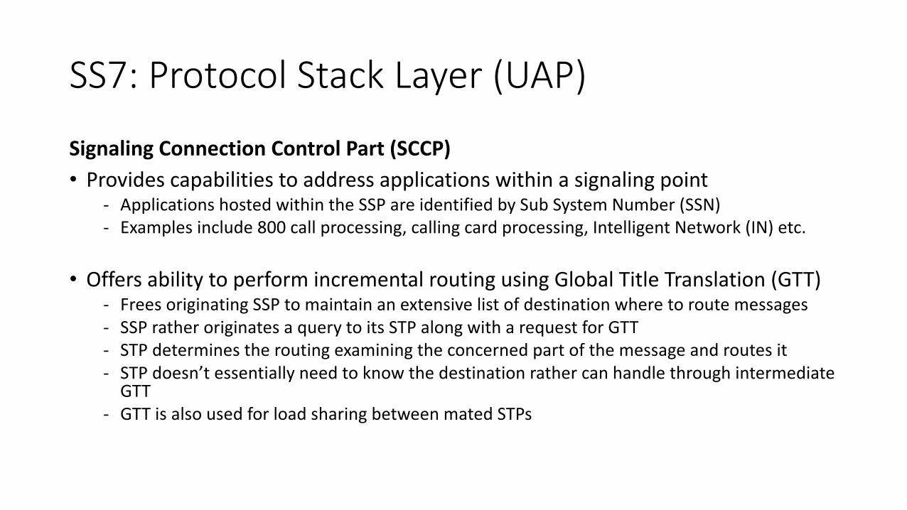
Signaling Connection Control Part (SCCP)• Provides capabilities to address applications within a signaling point
- Applications hosted within the SSP are identified by Sub System Number (SSN)- Examples include 800 call processing, calling card processing, Intelligent Network (IN) etc.
• Offers ability to perform incremental routing using Global Title Translation (GTT)- Frees originating SSP to maintain an extensive list of destination where to route messages- SSP rather originates a query to its STP along with a request for GTT- STP determines the routing examining the concerned part of the message and routes it- STP doesn’t essentially need to know the destination rather can handle through intermediate
GTT- GTT is also used for load sharing between mated STPs

SS7: Protocol Stack Layer (UAP)
ISDN User Part (ISUP)• Defines the messages and protocol used for establishment and tear down of
voice and data calls over Public Switched Telephone Networks (PSTN)• Manage trunk network on which they rely• Exclusively rely on MTP to transport messages between concerned nodes
Telephone User Part (TUP)• Defines the messages and protocol used for communication between
applications defined as subsystem within nodes• ISUP predecessor for PSTN signaling• Obsoleted by ISUP in most countries

SS7: Protocol Stack Layer (UAP)
Transaction Capabilities Application Part (TCAP)• Defines the messages and protocol used for communication between
applications defined as subsystem within nodes• Used for communication of messages for 800 calls, calling cards & INs• Use SCCP for transport
Operations, Maintenance, & Administration Part (OMAP)• Defines messages & protocols defined to assist administrators of SS7 network• Procedures for validating network routing tables and for diagnostics• Includes messages using both MTP & SCCP for routing
SS7: ISUP Call Flow

SS7: Signaling Link Contents
• Signaling information transmitted through the signaling links are called SignalingUnits (SUs)• Three types of SUs are defines in SS7 protocol:
• Message Signaling Units (MSUs)• Link Status Signaling Units (LSSUs)• Fill-In Signaling Units (FISUs)
• All transmission in the SS7 signaling links are broken into in 8 bit bytes alsoreferred to as octets• SUs on a link are delimited by a 8 bit flag with a unique pattern 01111110• Any occurrence of the flag within the link indicates end of an SU and beginning ofa new one• Data within an SU containing the pattern of a flag is being handled by bitmanipulation technique and being reconstruction after transmission is complete

SS7 Signaling Unit: Definition
Fill-In Signal Unit (FISU)• Doesn’t carry any information payload • Occupy the link while there is no MSU or LSSU in the link• Facilitate constant monitoring of signaling link in absence of signaling traffic• Cal also be used for acknowledgement of receipt of signaling messages through BSN
& BIBLink Status Signaling Unit(LSSU)
• Used to communicate link information between the nodes at the end of each signaling link
• Information is contained in the status field of the SU• Cal also be used for acknowledgement of receipt of signaling messages through BSN
& BIB

SS7 Signaling Messages: MSU Definition
Message Signaling Units (MSUs)• MSUs are the workhorses for SS7 Network• All signaling associated with call setup, teardown, database query & response,SS7 network management takes place using MSUs• MSUs are considered as basic envelop for transmission of all addressedsignaling information within SS7 network• Different types of MSU carry different signaling information• All MSU have certain fields in common differing only in the type of messagethrough Service-Information Octet & Signaling Information field

SS7 Signaling Messages: MSU Structure
• Functionality of an MSU is identified by the actual content of “Service Information Octet” which is an 8-bit field • Service Information Octet contains three types of information
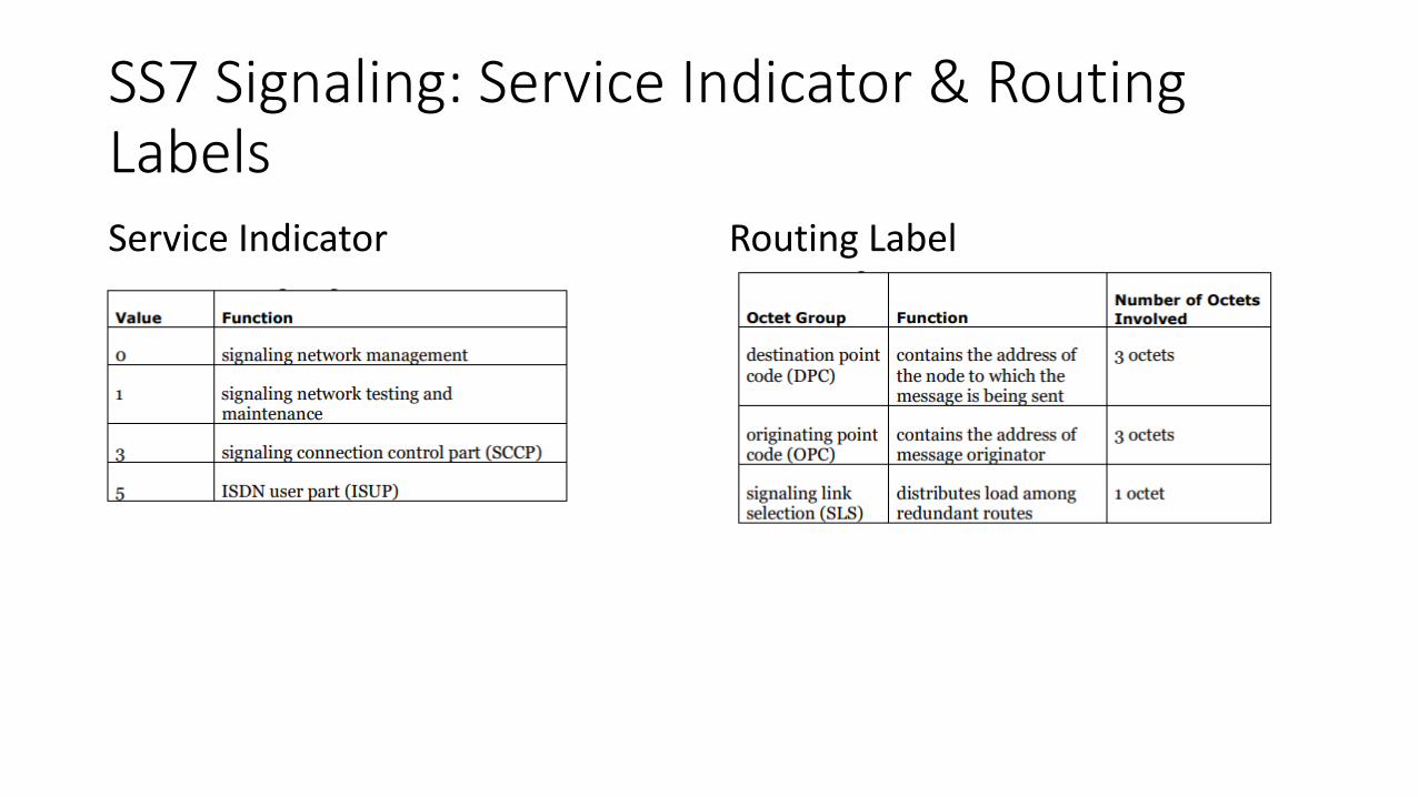
- Four bits are used to indicate the type of information contained in the signaling information field, also referred to as service indicator
- Two bits are used to indicate whether the message is indented for use in national or international network
- Remaining two bits are used to identify message priority with value from 0 to 3, with 3 being the highest priority. Priority only matters where there in congestion in the network
SS7 Signaling: Service Indicator & Routing Labels
Routing LabelService Indicator

SS7: Signal Unit StructureAll three SU types have a set of common fields used by MTP 2:• Flags delimit SU. It marks the end of one SU and
beginning of another one• Checksum is an 8 bit sum intended to verify that
the SU has passed the link error free. A retransmission of SU is requested is the recalculated sum doesn’t match with the originally calculated sum
• Length Indicator indicates the number of octets between itself and the checksum. FISSU has length indicator 0, LSSU has 1 or 2 and MSU has more than 2
• BSN/BIB FSN/FIB Backward Sequence Number, Backward Indicator Bit, Forward Sequence Number, Forward Indicator Bit confirms receipt of SU and ensures they are received in order. These also provides flow control

SS7 Signaling: Addressing
• SS7 addresses follow a three level hierarchy:- Network- Cluster- Member
• Each level consists of 8 bit and values range from 0 to 255• Combining these three levels forms an address called point code• Network numbers are assigned on a nationwide basis by a neutralparty (e.g. BTRC)• Cluster is being defined as part of network• Individual signaling points are considered to belong to a cluster

Short Message Service: SMS
• Technology that enables sending and receiving text messages between mobile phones• First appeared in Europe in 1992• Included in GSM standard right at the beginning• It was ported to other wireless technologies like CDMA & TDMA
shortly after• SMS standards were originally developed by ETSI• Currently 3GPP is responsible for development and maintenance of
SMS standards

SMS: Characteristics
• Supports languages internationally and works with any languages supporting Unicode (e.g. Arabic, Chinese, Japanese, Korean etc.)• SMS can carry binary data in parallel to texts which enables it to carry
ringtones, pictures, logos, wallpapers, business cards (VCards) and WAP configurations• Supported by all GSM mobile phones and almost all subscription plans
offered by the operators include inexpensive SMS service• One SMS can contain a maximum 140 bytes (1120bits) of data
• 160 characters if 7 bit character encoding is used (e.g. Latin characters like English alphabets)
• 70 characters if 16 bit character encoding is used (e.g. Non Latin characters like Chinese characters)

SMS Call Flow

SIP: In a nutshell
• Session Initiation Protocol (SIP)• Most common protocol used inVoIP technology• Application layer signalingprotocol to create, modify andterminate sessions betweenmultiple participants• Can be used for voice, video,instant messaging, gaming etc.

SIP Components
Entities those help SIP to create its network:• User Agents (UA)• Proxy Server• Registrar Server• Redirect Server• Location Server
SIP Components: User Agents
• Endpoints in a SIP network those are responsible for creating, modifying and terminating sessions • Considered to be the most intelligent component in SIP network• Users agents includes but not limited to softphones, mobiles, laptops• Two categories of user agents based on their role:• User Agent Client (UAC): sends request and receives response• User Agent Server (UAS): receives request and sends response
• SIP is based on clients server architecture where caller’s phone acts as client and while callee’s phone acts as server
SIP Components: ServersProxy Server
• Plays the role of a router• Have intelligence to understand the SIP request and send it ahead with the help of
URI• Sits in between two user agents• There can be a maximum of 70 proxy servers in between a source & destination UAs
Registrar Server• Accepts registration requests from user agents• Helps UAs to authenticate themselves within the network• Stores URI & location of users in a database to help other SIP server under same
domain

SIP Components: ServersRedirect Server• Receives requests and looks up
the intended recipient of the request in the location database created by the registrar server
Location Server• Provides information of caller’s
possible location to the proxy and redirect servers

SIP Methods

SIP Method: INVITE
• Used to initiate a session with aUser Agent• Used to establish a mediasession between the user agents• Can contain the mediainformation of the caller in themessage body• A session is consideredestablished if the INVITEreceives a success response oran ACK has been sent
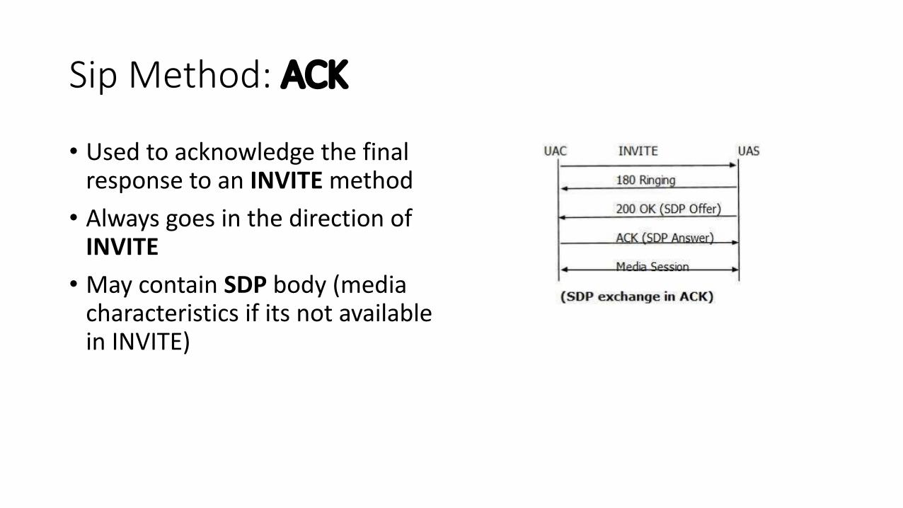
Sip Method: ACK
• Used to acknowledge the final response to an INVITE method• Always goes in the direction of
INVITE• May contain SDP body (media
characteristics if its not available in INVITE)

SIP Method: OPTIONS
• This method is used to query proxy server or a User Agent about its capabilities and discover its current availability• The response to a request lists the capabilities of the user agent or
the server• A proxy never generates an OPTIONS request

SIP Methods: CANCEL
• Used to terminate a session whichis not established• User Agent use this request tocancel a pending call attemptinitiated earlier• It can be sent either by a useragent or a proxy server• CANCEL is a hop by hop request(goes through the elementsbetween the user agents andreceives the response generated bythe next stateful element)
SIP Methods: BYE & REGISTER
• BYEMethod is used to terminatean established session• Can be sent either by the calleror the callee to end a session• Can’t be sent by a proxy server• Normally routes end to end,bypassing proxy server• Can’t be sent to a pendingINVITE or an unestablishedsession
• REGISTER request performsregistration of a User Agent to aSIP network• Sent by a User Agent to aRegistrar Server• Contains the time period(3600sec)• One user agent can send aREGISTER request on behalf ofanother User Agent. This isknown as third party registration

SIP Responses

SIP CODECS
CODEC is the Short form of Coder Decoder• First it converts and analog signal to its equivalent digital form so that it can
be easily transmitted• Thereafter it converts the compressed digital signal back to its original analog
form so that it can be replayed
SIP uses following major CODECS• G.711: 8KHz sampling rate, 64 kbps• G.723.1: Two variants of 6.4 kbps & 5.3 Kbps respectively• G.729: 8KHz sampling rate, 8 kbps, Voice Activity Detection

SIP Call Flow: Using Proxy

SIP Call Flow: Using Gateway

SIP Call Flow: SIP to ISUP (International Call)

Telecom Traffic Engineering: Terminologies
• ErlangUnit of traffic density in telecommunication system. One channel occupied for 3600 seconds in an hour yields an Erlang traffic
• Busy Hour Call Attempts (BHCA)Number of attempts in a SSP in a given hour
• Answer to Seizure Ratio (ASR)Total Answered Calls/Total Attempts
• Average Call Duration (ACD)Total Billed Minutes / Total Successful Calls
• Mean Holding Time (MHT)Total Billed Minutes / Total Attempts