telelink data link communication system for the global...
TRANSCRIPT

TELELINK DATA LINKCOMMUNICATION SYSTEMFOR THE GLOBAL EXPRESS
REFERENCE GUIDE FOR GLOBAL DATACENTER SERVICES
Doc 176-9001-981Version 3

2

3
TELELINK DATA LINKCOMMUNICATION SYSTEM
FOR THE GLOBAL EXPRESS
REFERENCE GUIDE FOR GLOBAL DATACENTER SERVICES
Document #176-9001-981Version 3

4
Global Data Center(425) 885-8100 Global Data Center, or(888) 634-3330 Toll Free in U.S. & Canada(425) 885-8930 Facsimile
[email protected] E-mail
Via ACARS Message�GLOBAL� At the message subject prompt.
Honeywell Main Number
(800) 707-4555 Directory Assistance Morristown, NJ
(800) 421-2133 Customer Access Center Phoenix, AZ
(888) TALK-FMS Honeywell FMS Support
Contact Information

5
CONTACT INFORMATION........................................................ 4
WHAT IS THE GLOBAL DATA CENTER .................................. 7
DATALINK SERVICES............................................................... 7
ACARS NETWORK .................................................................. 8
DATALINK ACCESS .................................................................. 9
DATALINK INDEX PAGE ONE ................................................. 9
DATALINK INDEX PAGE TWO ................................................. 10
COM CONTROL ..... .................................................................. 11
VHF Network Access ....................................................11
VHF Network Stations ...................................................12
SATCOM .......................................................................13
FLIGHT PLAN RECALL ............................................................. 14
WINDS..................... .................................................................. 15
POSITION REPORTS................................................................ 16
PREFLIGHT SERVICES ............................................................ 16
ATIS..................... .................................................................. 17
TEXT WX............. .................................................................. 18
TWIP.................... .................................................................. 19
Pre-Departure Clearance Request......................................... 20
Using Call-Signs ........................................................ 21
OCEANIC CLEARNACE ............................................................ 22
East Bound .......... .................................................................. 22
West Bound ......... .................................................................. 22
Using a Call-Sign. .................................................................. 23
Table of Contents

6
INFLIGHT SERVICES............................................................... 24
TEXT WX............. .................................................................. 24
CREATE MESSAGE ................................................................. 25
Text Message Addressing..................................................... 26
Message Address Examples................................................. 27
RECEIVED MESSAGES........................................................... 28
CONFIGURATION CHANGE PROCEDURES ......................... 29
Table of Contents

7
What is the Global Data Center?The TeleLink management unit is a data communication systemthat provides two way air-to-ground communication and permitsaccess to a wide variety of flight information services. Data may betransmitted through either the VHF (ACARS) or Satellite networks.All communications are routed through the Global Data Center(GDC) located in Redmond, Washington.
The Global Data Center (GDC) provides comprehensive datamanagement, message handling, flight planning, and other flightrelated products and services. Datalink messages are normallyhandled automatically by the GDC computer network, and in manycases no human intervention is necessary. However, often times itis desirable to have special handling, therefore users areencouraged to contact the Global Data Center staff at anytime,24/7, for one-on-one assistance. The GDC is staffed withdedicated aviation professionals who are specially trained andeager to help. The GDC is therefore a virtual extension to yourflight department and a communication resource to link your flightdepartment with all segments of aviation.
Using the TeleLink System, the following is a list of the currentdata link services available through the Global Data Center.
Digital ATIS (D-ATIS)Flight Plan Upload to the FMSMessagesOceanic ClearancesPre-Departure Clearances (PDC)SIGMETSTake OFF and Landing TimesTerminal Weather (TAF/METAR/NOTAMS/PIREPS)TWIP (Doppler Warnings)Winds Aloft
On the ground, users may also access GDC services over thetelephone or through a ground-based computer interface utilizingwidely distributed GDC communication software.

8
ACARS NETWORKDatalink communications are normally transmitted via one of threeVHF networks operated by ARINC, AVICOM, or SITA. Thiscombined network (which is also utilized by most scheduledairlines) is termed the ACARS (Aircraft Communication andReporting System) network. GDC subscribers are automaticallyregistered to use all three VHF networks.
ARINC North America, and Hawaii
AVICOM Japan
SITA Africa, Europe, South America, Central America,The Caribbean, Asia, and the South Pacific
ACARS VHF stations are stand-alone facilities and are usually notrelated to ATC voice communication or navigation facilities. TheTelelink communications management unit (mini-CMU) uses aVHF transceiver to communicate over the ACARS network. TheCMU also interfaces with satellite communication systems for datacommunications via the satellite network. Communicating insatellite mode is normally used when the aircraft is out of range ofVHF stations. Although the CMU can automatically switchbetween satellite and VHF, the pilot may opt to manually switchbetween modes at anytime.

9
DATALINK ACCESS
The DATALINK INDEX is accessed on the NAV INDEX menu.
DATALINK INDEX (page 1 of 2)
Accessed from the NAV page, the DATALINK INDEX is theprimary page for control of datalink communication and TeleLinkfunctions. The DATALINK INDEX is comprised of two pages.
NAV INDEX 1 / 2
< FPL LIST FPL SEL >
< WPT LIST DATALINK >
< DEPARTURE ARRIVAL >
< POS SENSORS TUNE > SCRATCHPAD
DATALINK INDEX 1 / 2
< FLT PLAN WINDS >
< REPORTS PREFLIGHT >
< TEXT WX INFLIGHT >
< CREATE MSG RCVD MSGS > SCRATCHPAD
1L
2L
3L
4L
1R
3R
2R
4R
1R
2R
3R
4R
1L
3L
2L
4L

10
DATALINK INDEX (page 2 of 2)
DATALINK INDEX.
It is recommended that at each power up that the COMMCONTROL pages be reviewed in order to assure that data linktransmissions will be sent by the desired network (VHF orSATCOM).
While in VHF mode make sure that AIR CANADA is turned OFFsince AIR CANADA has been decommissioned and is no longer inservice.
DATALINK INDEX 2 / 2
< COMM CONTROL OOO1 >
< MAINTENANCE ADDRESS >
SCRATCHPAD
1L
2L
3L
4L
1R
2R
3R
4R

11
COM CONTROL
The TeleLink COM CONTROL page is accessed from thesecond page of the DATALINK INDEX. This page is used toconfigure the system communication preferences, and includesprovisions for turning on or off the VHF, SAT, and TELEPHONYsystems.
Choose the desired communication network settings from theCOM CONTROL page. The CMU normally defaults to the VHFNetwork (ACARS). The Satellite (SAT) network is normally usedwhen out of range of a VHF station. Transmission via theTelephony Network (Magnastar) is not currently supported.
VHF NETWORK
DATALINK INDEX 2 / 2
< COM CONTROL OOO1 >
< MAINTENANCE ADDRESS >
SCRATCHPAD
ACARS COM CONTROL 1 / 1
< VHF NETWORK
< TELEPHONY
< SATCOM
<DATALINK SCRATCHPAD
1R
2R
3R
4R
1L
2L
3L
4L
1R
2R
3R
4R
1L
3L
2L
4L

12
VHF NETWORK
The VHF NETWORK page is accessed from the COM CONTROLpage. This page is used to configure the TeleLink VHF settings.The following are optimized VHF settings for the widest VHFcoverage.
If it is desirable not to transmit via any network, use the OR selectkeys to TURN OFF the particular network on these pages. AIRCANADA should be turned OFF since the network has beendecommissioned.
ACARS VHF NETWORK 1 / 2
ARINC OR >ON
SITA OR >ON
AIR CANADA OR >OFF
<COM CONTROL
ACARS VHF NETWORK 2 / 2
AVICOM OR >ON
VHF FREQUENCY OR >-- -- -- . -- -- --
VOICE
<COM CONTROLSCRATCHPAD
1L
3L
2L
4L
1R
2R
3R
4R
1L
2L
3L
4L
3R
2R
1R
4R

13
SATCOM NETWORK
The SATCOM NETWORK page is accessed from the COMCONTROL page. This page is used to configure the SATCOMsystem settings.
Select TRACKER TIMER to ENABLE to ready the SATCOMsystem for datalink transmission. If it is desirable to transmit viaSAT and not to transmit via the VHF network, TURN OFF all VHFnetworks and leave the SATCOM Tracker Timer ENABLED.
The AUTO RETURN TO COMM setting is used to switch theSATCOM system back to the VOICE setting. This should be left inthe ENABLED setting unless the SATCOM system is to bededicated to data transmission only.
ACARS SATCOM 1 / 1
TRACKER TIMERENABLED OR >
AUTO RETURN TO COMMENABLED OR >
<COM CONTROL
1L
2L
3L
4L
1R
2R
3R
4R

14
FLIGHT PLAN RECALL
Flight plan recall is accessed from the DATALINK INDEX page byselecting FLT PLAN.
Previously computed flight plans stored at the Global Data Centercan be recalled from the DATALINK FLT PLAN page by enteringthe flight plan recall number on the scratchpad then transfer thedata in the FPL ID field, and press SEND RQST.
When a flight plan request is received at the Global Data Center itis processed and the flight plan along with weather for thedeparture airport, destination airport, alternate airport (if filed),SIGMETS, and PIREPS are sent to the aircraft automatically.
When the flight plan is received the FPL REVIEW prompt willappear. Selecting the FPL REVIEW will allow review of the flightplan and a choice to select uplink winds with the flight plan. Otherservice provider�s flight plans can be requested here as well aslong as their flight plan has been sent to the Global Data Centerfor recall.
ACARS DATA LINK FLT PLAN 1 / 1
< FPL IDD1234
FPL REVIEW >
< DATALINK SEND RQST >

15
WINDS
Winds aloft can be accessed from the DATALINK INDEX byselecting WINDS. Winds can be �ACCEPT� from the flight planwithout looking at them or you may select �FPL WPTS� to vieweach waypoint. Manually entered waypoints are entered on thescratchpad and transferred to the blank line select key indicatedby �- - - -�.
Once a manually entered waypoint has been moved from thescratchpad a four-character space will appear below the lastmanually entered waypoint. Up to fifty-two way points can behand entered.
ACARS DATA LINK WINDS 1 / X
< FPL WPTS
KSEA
- - - -
< REJECT ACCEPT >
SCRATCHPAD

16
REPORTS
Currently the TeleLink unit does not send automatic positionreports but does support manual position reports. To send a POSREPORT select SEND POS REPORT. Current latitude andlongitude will be obtained from the FMS and will be transmitted tothe ground. FPL ID and SENDING FPL REPORT are currentlynot supported.
PREFLIGHT SERVICES
ATIS, TWIP, TEXT WX, DEPART CLX (PDC) and OCEANIC CLX arethe initial services offering from the PREFLIGHT page. Theremaining options will be added in the future. Access thePREFLIGHT page by selecting the PREFLIGHT line select key fromthe DATALINK INDEX.
ACARS PREFLIGHT 1 / 2
< ATIS TEXT WX >
< TWIP DEPART CLX >
< DELAY OCEANIC CLX >
< DATALINK
ACARS REPORTS 1 / 1
< FPL ID
< SENDING FPL REPORT
< SEND POS REPORT
< DATALINK

17
ATIS
ATIS request provides the ability to request Automatic TerminalInformation Service (ATIS) at airports that have this service.
Manually enter the airport ID on the scratch pad. Select theAIRPORT line select key to transfer the data then press SEND.
Contact the Global Data Center for a current list of ATIS airports.
ACARS ATIS 1 / 1
AIRPORT- - - -
DEPT OR >
SEND >
< RETURN

18
TEXT WX
By pressing the TEXT WX line select key, the TEXT WX pages aredisplayed. Up to two terminal weather stations may selected foreach TEXT WX request. STATION 1 will display the destinationairport, by default.
To request TEXT WX, first type the ICAO identifier of the desiredairport on the scratchpad, then press the line select key for thedesired station. Repeat this procedure for the second terminalweather request.
By default, METAR and TAF reports are automatically includedwhen transmitting the TEXT WX request. Press the NEXT key onthe FMS keypad to display the TEXT WEATHER Request page.
ACARS TEXT WX 1 / 2
< STATION 1 RCVD MSGS > KLAX
< STATION 2 - - - - -
SEND >
< RETURN KLGA
ACARS TEXT WEATHER 1 / 2
< TERMINAL ∗ RCVD MSGS >
< WINDS SIGMETS >
< PIREPS ∗ SEND >
< RETURN

19
TEXT WX � continued
The asterisk (∗) indicates the default weather products for everyTEXT WX request. To select or deselect any or all of the weatherproducts, press the corresponding line select key. The TEXTWEATHER Request page above indicates that each time a TEXTWX request is sent, METAR, TAF, NOTAMS, and PIREPS are to beincluded for the desired airport identifier(s).
Press the SEND line select key to transmit the request. �SENDING�displays above the SEND line select to indicate that the Telelinksystem is transmitting the request. When the VHF ground stationhas received the complete request, �SENT� is then displayed..
Pressing the RCVD MSGS line select will display the RCVD MSGSpage. This is a handy short cut when a new message has beenreceived.
Press the RETURN line select key to return back to the DATALINKINDEX.
TWIP (Terminal Weather Information for Pilots) (Doppler weather)
Doppler weather information within 15NM of some US airports isavailable. Enter the airport ICAO ID in the scratchpad and transferthe ID in the AIRPORT field and then press send.
Information regarding such items as gust fronts, heavy/moderateprecipitation, and storm movement within 15nm of the selectedairport will be transmitted to the aircraft.
ACARS TWIP 1 / 1
AIRPORT - - - -
SEND >
< PREFLIGHT

20
PRE-DEPARTURE CLEARANCE
The DEPART CLX (PDC) page is accessed from the PREFLIGHT pageby pressing the DEPART CLX line select key.
Even though the GDC computer requires only the departure ICAOidentifier (ORIG), it is necessary to enter data into each of the data fieldsin order to transmit the Pre-Departure Clearance request. Enter thedeparture airport for the ATC STATION, departure (ORIG), anddestination (DEST) using the ICAO identifier on the scratchpad. Enter acharacter or number for the GATE and ATIS fields (any character ornumber will do). When all the fields contain a character, press the SENDline select key to transmit the PDC request.
ACARS PREFLIGHT 1 / 2
< ATIS TEXT WX >
< TWIP DEPART CLX >
< DELAY OCEANIC CLX >
< DATALINK
ACARS DEPART CLX 1 / 1
< ATC STATION GATE > KORD 1
< ORIG ATIS > KORD Y
< DEST KDFW SEND >
< PREFLIGHT
1R
2R
3R
4R
1L
2L
3L
4L
4R
3R
2R
1R
4L
3L
2L
1L

21
PRE-DEPARTURE CLEARANCE (continued)
Press the SEND line select key to transmit the request. �SENDING�displays above SEND to indicate that the Telelink system is transmittingthe request. When the VHF ground station has received the completerequest, �SENT� is then displayed.
When the aircraft receives the PDC, a �NEW MSG� appears on thescratchpad. Press the RCVD MSGS line select key from the DATALINKINDEX. Press the line select key corresponding to the message thatcontains the PDC. If the PDC requires more than one page, press theNEXT and PREV keys to move back and forth.
CALL-SIGNS
When using a call-sign this page can not be used. The CREATE MSG2/2 page must be used. In the SUBJECT line simply type �PDC� plus thedeparture airport ICAO ID, special character such as a dash (-) and thenyour call-sign. (Example: PDCKORD-GLOBAL1.) A space may not beused between the airport ID and call-sign and the SUBJECT line islimited to twenty-four characters.
ACARS DEPART CLX 1 / 1
< ATC STATION GATE >KORD 1
< ORIG ATIS > KORD Y
< DESTKDFW SEND >
< PREFLIGHT
4R
4R
4R
4R
4R
4R
4R
4R

22
OCEANIC CLX
OCEANIC CLX provides the crew with a digitized messagecontaining the oceanic clearance. East bound clearances areautomatically forward to aircraft from the Global Data Centerprovided that the aircraft is maintaining data link communications.An oceanic clearance will be held at the Global Data Center untildata link communications to the aircraft have been established oruntil the clearance has timed out. If data link communications arenot being maintained, then an oceanic clearance should berequested as soon as possible, up to one hour before enteringOceanic Airspace. Usually, 70° West is used as a rule of thumb tobegin requesting your eastbound Oceanic Clearance. Due tovarying times that Gander issues Oceanic Clearances, you mayneed to request the clearance a second time.
EAST BOUND:
GANDER must be in the ATC STATION field. It is necessary toenter a character (any character will do) into each of the datafields in order to transmit the OCEANIC CLX request.
WESTBOUND: (future service)
All fields require an accurate entry. Enter the ATC STATION,ENTRY POINT, ENTRY TIME, FLT LEVEL, MACH speed, andFLT NO. When all fields are entered, press the SEND key totransmit the OCEANIC CLX request. The Oceanic Clearance willbe sent from the Global Data Center in the form of a newmessage.
ACARS OCEANIC CLX 1 / 2
< ATC STATIONGANDER OR >ENTRY POINT - - - - - - - - - - - -
ENTRY TIME - - - - Z SEND >
< RETURN

23
OCEANIC CLX USING A CALLSIGN
When using a call-sign it will be necessary to request an oceanicclearance from the CREATE MSG page two. On the SUBJECTline type �CLX� followed by the call-sign (no space between CLXand the call-sign). Press the �PREV PAGE� button and from theCREATE MSG page one, press SEND. The Oceanic Clearancewill be sent from the Global Data Center in the form of a newmessage.
NOTE: Remember to add �AGCS EQUIPPED� to the ATC remarkson your flight plan.
EXAMPLE:
ACARS CREATE MSG 2 / 7
< SUBJECT:CLXGLOBAL1
_ _ _ _ _ _ _ _ _ _ _ _ _ _ _ _ _ _ _ _ _ _ _ _ _
< DATALINK

24
INFLIGHT SERVICES
ATIS, TEXT WX, TWIP, and OCEANIC CLX are the initial servicesoffering from the INFLIGHT page. The remaining options will be added inthe future.
Access the INFLIGHT page by selecting the INFLIGHT line selectkey from the DATALINK INDEX. The ATIS, TEXT WX, TWIP, andOCEANIC CLX procedures are identical to the proceduredescribed in the PREFLIGHT pages.
ACARS INFLIGHT 1 / 2
< ATIS TEXT WX >
< TWIP OCEANIC CLX >
< ETA UPDATE FUEL UPDATE >
< DATALINK
1L
2L
3L
4L
1R
2R
3R
4R
25
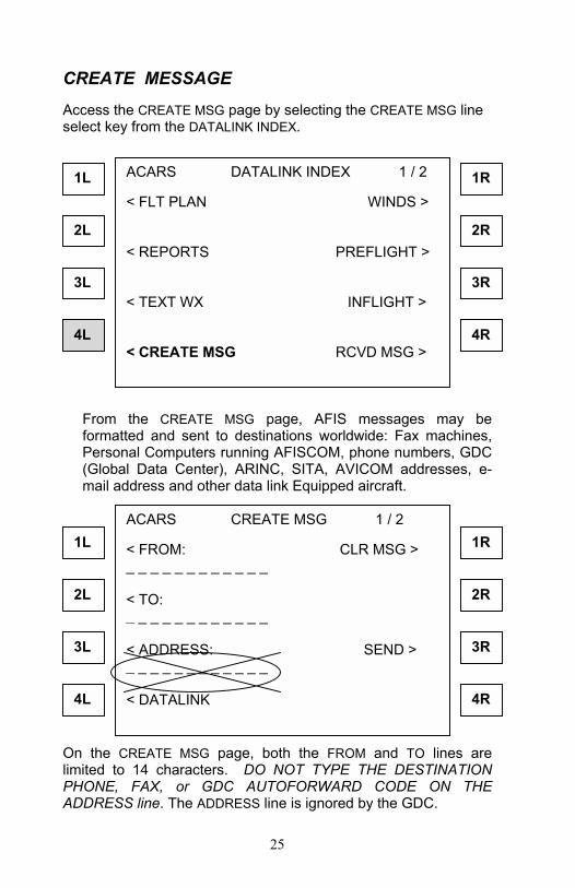
CREATE MESSAGEAccess the CREATE MSG page by selecting the CREATE MSG lineselect key from the DATALINK INDEX.
From the CREATE MSG page, AFIS messages may beformatted and sent to destinations worldwide: Fax machines,Personal Computers running AFISCOM, phone numbers, GDC(Global Data Center), ARINC, SITA, AVICOM addresses, e-mail address and other data link Equipped aircraft.
On the CREATE MSG page, both the FROM and TO lines arelimited to 14 characters. DO NOT TYPE THE DESTINATIONPHONE, FAX, or GDC AUTOFORWARD CODE ON THEADDRESS line. The ADDRESS line is ignored by the GDC.
ACARS DATALINK INDEX 1 / 2
< FLT PLAN WINDS >
< REPORTS PREFLIGHT >
< TEXT WX INFLIGHT >
< CREATE MSG RCVD MSG >
ACARS CREATE MSG 1 / 2
< FROM: CLR MSG >_ _ _ _ _ _ _ _ _ _ _ _
< TO:_ _ _ _ _ _ _ _ _ _ _ _
< ADDRESS: SEND >_ _ _ _ _ _ _ _ _ _ _ _
< DATALINK
1R
2R
3R
4R
1L
2L
3L
4L
4R
3R
1R
2R
1L
2L
3L
4L

26
CREATE MESSAGE (continued)
Use the SUBJECT line located on page 2 of the CREATE MSGpage. Press the NEXT key to display the second page CREATEMSG page to address the message.
Type the desired destination on the scratchpad and press theSUBJECT line select key. The code or number will be moved tothe SUBJECT line. Text messages may be up to 18 lines longand 24 characters per line. Type the text on the scratchpad andpress the corresponding line select key, on the left side of theCDU screen, where the text should be placed. To add a spacebetween word or characters use the slash key (/). If all three linesare filled and the message in not yet complete, then press theNEXT key on the FMS keypad, to display the next text page.
Use the CLR MSG line select key to delete all contents of themessage but the FROM, TO and ADDRESS fields.
When the message is complete, press the PREV key on the FMSkeypad until the first page of the CREATE MSG page is displayed,then press the SEND line select key.
ACARS CREATE MSG 2 / 7
< SUBJECT:F3122445992
ETA KDCA 2130Z. NEED 22000 LBS FUEL
_ _ _ _ _ _ _ _ _ _ _ _ _ _ _ _ _ _ _ _ _ _ _ _ _
< DATALINKCONFIRM CATERING FOR 0020 DEP
1R
2R
3R
4R
1L
2L
3L
4L

27
EXAMPLES AND FORMATS OF ADDRESSES AT THESUBJECT FIELD:
Auto Forward Code(s):
To send messages with a pre-determined number, e-mail orARINC/AFTN address - contact the Global Data Center to setupdesired codes. These codes will then be entered in the SUBJECTfield.
Codes can also be created for multiple destinations such as twofax machines. Again, contact the Global Data Center to setupdesired codes.
Recipient addresses:N12345 Datalink equipped aircraft425-885-8788 Telephone numberF4258858930 Fax numberA4258858947 PC with AFISComGDCOPS GDC auto forward codeAHDQGLXH ARINC addressNKSNAXGSX AFTN addressGDC Global Data CenterJEPP JeppesenARI Air Routing InternationalBASEOPS Base Ops InternationalUVAIR Universal Weather

28
RECEIVED MESSAGESAccess the RCVD MSG page by selecting the RCVD MSG lineselect key from the DATALINK INDEX and the TEXT WX pages.
From the RCVD MSG page, view all messages transmitted tothe aircraft including text messages, terminal weather, digitalATIS, TWIP and Pre Departure Clearances (PDC). Eachscreen displays up to three messages by message title, pressthe NEXT key to display additional received message pages.The message title is extracted from the first twenty-onecharacters of the message text.
Display the desired message by pressing the corresponding leftline select key. If the message is larger than one page, pressthe NEXT key on the FMS keypad to display the second pageof the message.
ACARS DATALINK INDEX 1 / 2
< FLT PLAN WINDS >
< REPORTS PREFLIGHT >
< TEXT WX INFLIGHT >
< CREATE MSG RCVD MSG >
ACARS RCVD MSGS 1 / 2
< ETA REPORT RECEIVED B
< TOWN CAR IS ON RAMP A
< CLEARED VIA THE SUMMA
< RETURN
1R
2R
3R
4R
1L
2L
3L
4L
1R
2R
3R
4R4L
3L
2L
1L

29
GLOBAL EXPRESS: TELELINKCONFIGURATION CHANGE PROCEDURE
To modify the Telelink default OPERATOR ID code:
1. Initialize the FMS and IRS systems. Then select theDATALINK option from the NAV INDEX page. PressNEXT to go to the second page of the DATALINKINDEX.
2. Press the MAINTENANCE option. You must have �GS�code in OPERATOR ID field. To change the code youmust go to the CONFIGURATION page of themaintenance menu and type the password 46639 inthe scratchpad -- then press the bottom right lineselect key. The system will say, �CONFIG PASSWORDACCEPTED�.
3. After it says, "CONFIG PASSWORD ACCEPTED" youcan change the operator ID code to GS on theAIRCRAFT page. After you've changed to theOPERATOR ID to GS, go back to CONFIGURATIONpage and choose the STORE option line select key towrite the changes to the configuration module. Thesystem may go blank for a while.
EXAMPLE: Accessed from the NAV page, the DATALINKINDEX is the primary page for control of datalinkcommunication and TeleLink functions.
DATALINK INDEX 1 / 2
< FLT PLAN WINDS >
< REPORTS PREFLIGHT >
< TEXT WX INFLIGHT >
< CREATE MSG RCVD MSGS > SCRATCHPAD
1R
2R
3R
4R
1L
3L
2L
4L

30
CONFIGURATION CHANGE PROCEDURE
MAINTENANCE page:
DATALINK INDEX 2 / 2
< COMM CONTROL OOO1 >
< MAINTENANCE ADDRESS >
SCRATCHPAD
1L
2L
3L
4L
1R
2R
3R
4R
MAINTENANCE 1 / 1
< CONFIG
< FAULT LOG
SCRATCHPAD
1L
2L
3L
4L
1R
2R
3R
4R

31
CONFIGURATION CHANGE PROCEDURE
CONFIG page:
CONFIG PASSWORD ACCEPTED page:
CONFIG 1 / 1
< AIRCRAFT STORE >
TEL COMM >
< VHF COMM SAT COMM >
< MAINTENANCE 46639 (then press LSK 4R) !
1L
2L
3L
4L
1R
2R
3R
4R
CONFIG 1 / 1
< AIRCRAFT STORE >
TEL COMM >
< VHF COMM SAT COMM >
< MAINTENANCE
CONFIG PASSWORD
1L
2L
3L
4L
1R
2R
3R
4R

32
CONFIGURATION CHANGE PROCEDURE
AIRCRAFT page:
CONFIG page:
AIRCRAFT 1 / 1
< TYPE OPERATOR ID >CGEX GS
< REGISTRATION N5678
< CONFIG GS (Scratchpad)
1L
2L
3L
4L
1R
2R
3R
4R
CONFIG 1 / 1
< AIRCRAFT (Press to save !) STORE >
TEL COMM >
< VHF COMM SAT COMM >
< MAINTENANCE
1L
2L
3L
4L
1R
2R
3R
4R

33
CONFIGURATION CHANGE PROCEDURE
Other Notes:• Make sure the system is using 131.550 for ARINC, not
131.450 MHz on the VHF communication page.
• The SAT system must be set to DATA, and there mustnot be a phone number in the telephony section of thecommunications page or it will use the Magnastarphone instead of satellite. (If it uses the Magnastar,the system will not switch to SAT because theMagnastar is not supported by the Global Data Center,and therefore the system will get stuck in that mode).Suggest you use VHF, leave SAT in DATA mode, anddelete the phone number in Telephony.
• When sending a message, use the subject fieldfor address info. The subject field is on page two ofthe message page. Leave the address field blank.Press PREV to go back to the first page of themessage -- then press SEND.
• When asking for TEXT WX or ATIS, the request fieldswill default to your departure and destination airports.If a different location is desired, line select the oneyou want to change, then press DEL to clear that field.
• For PDC, select DEPART CLX from the PREFLIGHTmenu. You must type the departure airport at ATCstation and ORIG fields. The other fields must have anentry or you can not transmit. Type what ever youwant to fill the field. (The GDC will ignore all otherfields)
• Ignore FUEL UPDATE, DIVERSION, and DELAY fields --we don't service them.
• Weather, PDC, and ATIS come up as a message.