telemetric interplanetary regolith explorer for seismic ... · pdf filetelemetric...
TRANSCRIPT

SPRING FINAL REVIEW
TELEMETRIC INTERPLANETARY REGOLITH EXPLORER FOR SEISMIC
INVESTIGATION OF ASTEROID SURFACES
Ian Barry
Rachael Collins
Jonathon Fraker
Patrick Haas
Tom Johnson
Austin Lillard
John Marcantonio
Scott Taylor
Aerospace Engineering Sciences
University of Colorado
21 April 2014

OUTLINE
Project Objective
Design Description
Test and Results
Communications System
Power System
Mechanical System
Systems Engineering
Project Management
2

PROJECT OBJECTIVE

MISSION CONOPS
4
18 month
travel time
Deploy Explosive
Pods (red) and
GeoPods (grey)
Surface Operations
Landing
GeoPod
records
data while
descending
2 1
2
20 minute contacts
every 2.26 hours
0.1-10 km
Range
300 min
Touchdown with
surface, data
recorded while
settling
10 min 10 days
Deploy, Descent, and Landing
14 hour
settling time
Spacecraft Orbits
Asteroid for 10 days
Explosive Pod
detonates; GeoPod
collects data with
Accel and Insts.
Science data
transmitted when link
is available with the
orbiting satellite
Accel is
turned on;
GeoPod is
separated
TIRESIAS Focus:
GeoPod
-Power
-Communication
-Internal Structure
Launch
1
Asteroid Surface
Accel and
Insts. activated
after settling
~5 min 14 hours

During this time, the power
system must regulate and
distribute power to all of the
components
Heaters are not necessary for
ground testing. Representative
loads will be used for simulation
The internal structure must
integrate the components and
the power system into the
GeoPod shell (provided by Ball)
Thermistors
w/MUX
Receiver Receiver
ADC ADC
PROJECT CONOPS
GeoPod
Accelerometer
C&DH Board
Transmitter
Accelerometer
C&DH Board
Transmitter
Internal
Structure
1 ft
3lb weight
Thermistors
w/MUX
Power
Weight dropped near fully
integrated GeoPod GeoPod detects seismic waves 3-axis accelerometer measures
response
BASIX mission will use both a
GeoPhone and an
Accelerometer
Our project will sample each axis
of the accelerometer twice to
simulate the GeoPhone,
because commercial
GeoPhones are too large,
heavy, and expensive for our
project
Ball is receiving a custom
GeoPhone
ADC converts 6 analog channels
(2 signals for each
accelerometer axis) into a digital
signal.
C&DH board samples and stores
the digital data from the ADC at
500Hz
Data from the multiplexed
thermistors (“housekeeping
data”) is sampled at 500Hz and
stored at 80 bits/s
The C&DH Board continues to
sample both the accelerometer
data and the thermistors for 15
minutes
Commands are received over
the next 20 minutes to start
transmissions of data
20 minutes represents a contact
window
Packetized accelerometer and
thermistor data is transmitted
according to received
commands
1.5
ft
Heaters
5

Level 1
Develop communication system
Store and forward accelerometer data
Receive commands from simulated mother satellite to playback telemetry
Test command and data handling with simulated seismic activity
Design internal structure to interface with shell
Level 2
Integrate communication system into GeoPod internal structure
Design and model power system with enough storage for mission duration
Level 3
Internal power system distributes and regulates power to all components
Develop fully integrated standalone GeoPod
Additions
Develop and validate thermal model
LEVELS OF SUCCESS
6

DESIGN DESCRIPTION

FUNCTIONAL BLOCK DIAGRAM
8

STRUCTURE INTEGRATION
Power Board
Receiver
Transmitter
Arduino Due
ADC Board
9 Project Objective Design
Description Comm System
Power System
Mechanical System
Systems Engineering
Project Mgmt

ELECTRONICS BLOCK DIAGRAM
10 Project Objective Design
Description Comm System
Power System
Mechanical System
Systems Engineering
Project Mgmt

SOFTWARE ALGORITHM
11
Command Acceptance
Data Collection Mode
(15min Duration) Power Switching Mode Telemetry Playback Mode
Samples Accelerometer
Samples Temp Sensors
Packetizes Data
Writes Packets to Memory
Parameter Selects
Component (of 5)
Parameter Designates
On/Off
Switches Power Low/High
Parameter Selects Packet
(Playback Pointer/Retrans)
Reads Packet from
Memory
Writes Packet to
Transmitter
Project Objective Design
Description Comm System
Power System
Mechanical System
Systems Engineering
Project Mgmt

CRITICAL PROJECT ELEMENTS
12
Element Description Satisfaction
MSN.1 Mass < 5kg Fully assembled GeoPod has a mass of 4.49 kg
MSN.2 Integration with
external shell
All components securely mount to the internal structure that
integrates with the external shell
MSN.3 Collect science &
housekeeping data
15 minutes of science and housekeeping data successfully
sampled at 500 Hz and stored in memory
MSN.4 Transmit data to
Ground Station
Equipment (GSE)
Stored data was transmitted to GSE at 38 kbps with minimal delays
and bit errors. The recorded data (3.75 MB) was transmitted in 13
minutes, which is within the 20min pass duration
MSN.5 Maintain operable
thermal range
A thermal model to bound expected component temperatures
during operation was created and validated through sand box
testing
MSN.6 Provide, regulate, &
distribute power
Batteries and Power PCB provide adequate power with 94%
efficiency for 12 days of operation
MSN.7 Provide a path to
flight
All components selected are flight ready or can be easily replaced
with spaceflight qualified components
Project Objective Design
Description Comm System
Power System
Mechanical System
Systems Engineering
Project Mgmt

TEST OVERVIEW/RESULTS

COMMUNICATIONS SYSTEM

Max. Amplitude:
0.2 g’s
freq < 50 Hz
COMM REQUIREMENTS
Requirement Flows From Description
COM.1 MSN.3 6 channels of science data shall be sampled at 500 Hz.
COM.2 MSN.3 Science data shall be recorded such that a range of -2g to
2g is quantized with a resolution of 0.002g
COM.3 MSN.3,
MSN.4
The C&DH board shall interface with ADC, memory, power
board, and RF system.
COM.4 MSN.4 Uplink data rate shall ensure all stored telemetry is
transmitted during the 20 min contacts over 10 days
Asteroid 60o
Rotational
Period = 2.4hrs Orbital
Period =
124.1hrs
15 Project Objective Design
Description Comm System
Power System
Mechanical System
Systems Engineering
Project Mgmt

DATA COLLECTION TEST Goal: Measure data collection rate (COM.1) and
characterize signal conditioning output (COM.2)
16
Measure ADC conversion frequency,
Verify sampling rate
Measure data stored,
Verify recording rate
Measure SNR and bias of data,
Verify signal conditioning output
MUX
Redesign
Verified
Timing
Verified
CCSC
Verified
Dual (20/5V)
Power Supply
9V Power
Supply
SPI Logic
Analyzer
Signal
Generator
Project Objective Design
Description Comm System
Power System
Mechanical System
Systems Engineering
Project Mgmt

DATA COLLECTION RESULTS
17
Signal Conditioning (COM.2)
LSB of ADC = 0.15 mV
Accelerometer = 100mV/g
-50g to 50g range with 0.0015g
resolution
Software Timing (COM.1)
Required duration < 2 ms
Predicted duration = 1.126 ms
Tested duration = 1.121 ms
500 Hz met within 0.0021%
Project Objective Design
Description Comm System
Power System
Mechanical System
Systems Engineering
Project Mgmt

TELEMETRY PLAYBACK TEST Goal: Measure effective data transmission rate (COM.4) and identify bit errors
Verify ability to transmit 3.74 MB of data in 20 min. and receive commands to transmit
18
Receiver
MATLAB Processing
Stand
Measure data transmitted,
Verify transmission rate greater than 32 kbps
Send error packets,
Verify bit error identification
9V Power
Supply
Measure delay between command
and packet receipt,
Verify response to command
Hard line to
command
Test RX
Arduino
Bytes
Sent
Memory
Read
Checksums
Calculated
Project Objective Design
Description Comm System
Power System
Mechanical System
Systems Engineering
Project Mgmt

TELEMETRY PLAYBACK RESULTS
Data Transmission (COM.4)
38 kbps data rate achieved (> 32 kbps)
Transferred 3.74 MB of stored data in
13 min, 1.6 sec (within 20 min
contact)
Overhead consists of commanding
and MATLAB serial read
Entire mission stored data transferred
in 13 contacts or 1.25 days of
operations (Margin Factor = 8)
Successfully identified and retransmitted
5 packets (out of 15,000) each with a
single bit error
Errors most likely due to memory read
speed, not transmission
Takes 0.26sec to retransmit 5 pkts
Project Objective Design
Description Comm System
Power System
Mechanical System
Systems Engineering
Project Mgmt
Data Type Sampling Rate Storage
Acceleromete
r (315 min)
24 kbps 56.7 MB
Geophone
(15 min)
24 kbps 2.7 MB
Housekeepin
g
(12 days)
64 bps 8.3 MB
Packet
Overhead
72 bits/pkt 2.54 MB
Mission Total: 70.24 MB
Total Transfer Time: 245 min (13 contacts)

POWER SYSTEM

POWER REQUIREMENTS
Critical Components
Batteries
Capacity and size
Power Regulation and Distribution
Efficiency and accuracy
Requirement Flows From Description
EPS.1 MSN.3,
MSN.4
The power system shall output voltage lines at 5, 9.5, 20,
and 12 volts
EPS.2 MSN.5 The batteries shall supply power for 12 days of operations
EPS.3 MSN.1 Power Distribution board shall fit on 4.25x4.25 in. PCB
EPS.4 EPS.1,
EPS.2
The Power Distribution board must be >90% efficient
21 Project Objective Design
Description Comm System
Power System
Mechanical System
Systems Engineering
Project Mgmt

POWER VERIFICATION
22
Goal: Measure regulation accuracy (EPS.1) and power board efficiency (EPS.4)
27V
Supply
12V
Supply
10-kΩ
Load
200-Ω
Load
25-Ω current
sense resistors
25-mΩ current
sense resistors
110-mΩ current
sense resistors
Measure Current and Voltage,
Verify accuracy and efficiency
33-Ω
Load
Project Objective Design
Description Comm System
Power System
Mechanical System
Systems Engineering
Project Mgmt

VOLTAGE ACCURACY TEST
23
Req EPS.1: Voltage Lines
Voltage lines measured over a variety of input voltage ranges to determine
limiting values
9.5V regulator met within 1%
20V regulator met within 5%
Project Objective Design
Description Comm System
Power System
Mechanical System
Systems Engineering
Project Mgmt

EFFICIENCY RESULTS
24 Project Objective Design
Description Comm System
Power System
Mechanical System
Systems Engineering
Project Mgmt
Req EPS.4: 90% Efficiency
Power board efficiency was measured over varied loads
Based on error in voltage measurements and resistor values, efficiency was
measured to a 0.5% accuracy
All measured power board efficiencies > 92%
0.00
20.00
40.00
60.00
80.00
100.00
120.00
80 130 180 230 280 330
Eff
icie
ncy
Load on 5V Regulator (Ω)
Efficiency of Power Board for Varied 5V Load
Efficiency of 5V Total Efficiency
91.00
92.00
93.00
94.00
95.00
96.00
97.00
98.00
99.00
15 20 25 30 35 40 45
Eff
icie
ncy
Load on 9V Regulator (Ω)
Efficiency of Power Board for Varied 9V Load
Efficiency of 9V Total Efficiency
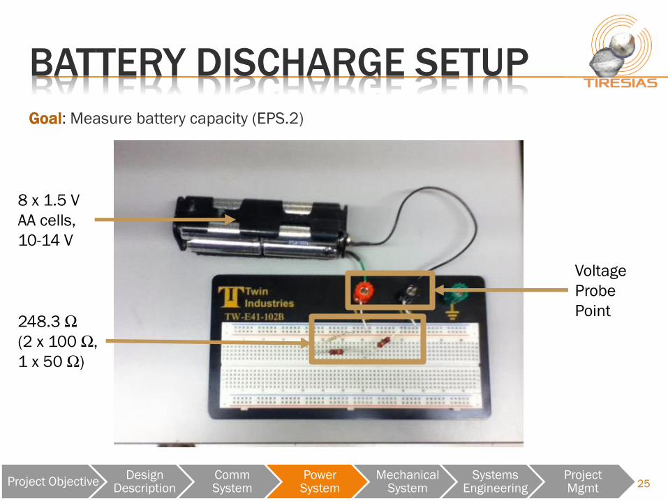
BATTERY DISCHARGE SETUP
248.3 Ω
(2 x 100 Ω,
1 x 50 Ω)
8 x 1.5 V
AA cells,
10-14 V
Voltage
Probe
Point
Goal: Measure battery capacity (EPS.2)
25 Project Objective Design
Description Comm System
Power System
Mechanical System
Systems Engineering
Project Mgmt

BATTERY DISCHARGE RESULTS
Co
nse
rvative
Ca
pa
city: 5
10
Wh
Re
qu
ired
Ca
pa
city: 3
80
Wh
Direct Sunlight
Heats Up Batteries
Battery Capacity (EPS.2)
Required capacity of
batteries: 380 Wh
Achieved capacity of
batteries: 510 Wh
Margin of 34%
26 Project Objective Design
Description Comm System
Power System
Mechanical System
Systems Engineering
Project Mgmt

POWER DISTRIBUTION BOARD
27
9.5 V Switching Regulator
Tem
pera
ture
Monitoring S
yste
m
C&
DH
Co
nn
ecti
on
s
5V Linear Regulator 20V Linear Regulator
Tra
nsm
itte
r/R
eceiv
er
Connections
PCB Size (EPS.3)
Power board must fit
within 4.25 in by 4.25 in
printed circuit board
Project Objective Design
Description Comm System
Power System
Mechanical System
Systems Engineering
Project Mgmt

POWER DISTRIBUTION BOARD
28
9.5 V Switching Regulator
Tem
pera
ture
Monitoring S
yste
m
C&
DH
Co
nn
ecti
on
s
5V Linear Regulator 20V Linear Regulator
Tra
nsm
itte
r/R
eceiv
er
Connections
PCB Size (EPS.3)
Power board must fit
within 4.25 in by 4.25 in
printed circuit board
Power board
successfully integrated
into GeoPod Structure
Project Objective Design
Description Comm System
Power System
Mechanical System
Systems Engineering
Project Mgmt

MECHANICAL SYSTEM

MECHANICAL REQUIREMENTS
Requirement Flows From Description
MCH.1 MSN.2 The internal structure shall integrate with the
manufactured GeoPod shell
MCH.2 MSN.2 The power and electrical subsystems shall be accessible
for extraction without the removal of other components
MCH.3 MSN.5 A thermal model shall be created to ensure subsystems are
within operating temperatures in the testing environment
MCH.4 MSN.7 All internal structural components shall be manufacturable
using on campus resources
30 Project Objective Design
Description Comm System
Power System
Mechanical System
Systems Engineering
Project Mgmt

31
MASS BUDGET
Mass Budget (MSN.1)
Actual Margin of 0.51 kg or 10.2%
Increase due to addition of wiring and battery packaging
Project Objective Design
Description Comm System
Power System
Mechanical System
Systems Engineering
Project Mgmt

SUBSYSTEM INTEGRATION TEST
32
Requirements Satisfied
MCH.1
MCH.2
MCH.4
Power Board
Receiver
Transmitter
Arduino Due
ADC Board
Project Objective Design
Description Comm System
Power System
Mechanical System
Systems Engineering
Project Mgmt

THERMAL VERIFICATION MODEL
33
Cold Case:
Hot Case:
Internal Structure Material:
Aluminum 6061
Subsystem
Op.
Range
[°C]
Temp at
Steady
State
[°C]
Temp
Change
[°C]
Arduino
Due/ADC
Cold: -40
Hot: 85
Cold: 21.47
Hot: 23.88
+0.47
+2.88
Power Board Cold: -40
Hot: 140
Cold: 21.46
Hot: 23.85
+0.46
+2.85
Battery Pack Cold: -20
Hot: 55
Cold: 21.55
Hot: 23.97
+0.55
+2.97
Transmitter/
Receiver
Cold: -20
Hot: 50
Cold: 21.50
Hot: 23.93
+0.50
+2.93
Thermal Operating Range (MCH.3)
Project Objective Design
Description Comm System
Power System
Mechanical System
Systems Engineering
Project Mgmt

THERMAL VERIFICATION Goal: Isolate and measure modeled thermal conductive resistances (MCH.3)
Resistances independent of thermal loads, symmetric within bounds
Resolution of 1.7 K/W needed, 0.013 K/W achieved (quadrature addition of error in power and temperature measurements)
Various levels of integration with and without batteries
34
Measure steady-state temperatures over
representative orthant of pod
Verify modeled thermal resistances
LabView VI NI 9213 DAQ
Surface
Thermocouple Stefaan
Van Wal’s
Gravel Box
5 Interior
Thermocouples
70W Heater
115 VAC
Wall Outlet Variac
V
Calibrated to
Precision σ = 0.13 K
Power Measured
to 2mW Accuracy
Project Objective Design
Description Comm System
Power System
Mechanical System
Systems Engineering
Project Mgmt
T5
T4
T3 T2
T1
T0
Structure Fit-
Checked and
Integrated

THERMAL TEST RESULTS
35
Internal Structure Material:
Aluminum 6061
Thermocouple
Station
Model
Temp
[°C]
Actual
Temp
[°C]
Temp
Deviance
[°C]
Temp 0 Cold: 22.28
Hot: 26.13
22.90 -0.62
+3.23
Temp 1 Cold: 22.28
Hot: 26.09
22.81 -0.53
+3.28
Temp 2 Cold: 22.27
Hot: 25.67
22.78 -0.51
+2.89
Temp 3 Cold: 22.26
Hot: 25.17
22.69 -0.43
+2.48
Temp 4 Cold: 22.26
Hot: 24.72
22.70 -0.44
+2.02
Temp 5 Cold: 22.21
Hot: 23.44
22.40 -0.19
+1.04
Project Objective Design
Description Comm System
Power System
Mechanical System
Systems Engineering
Project Mgmt
Thermal Modeling (MCH.3)
20.00°C
21.00°C
22.00°C
23.00°C
24.00°C
25.00°C
26.00°C
27.00°C
T0 T1 T2 T3 T4 T5
Te
mp
era
ture
Thermocouple Location
Thermal Model Validation in Lab Conditions
Cold Case Hot Case Experimental

THERMAL SPACE CASE
36 Project Objective Design
Description Comm System
Power System
Mechanical System
Systems Engineering
Project Mgmt
Method
Calculate bounding model
temps at different orbital
positions
1.01 AU (Perihelion)
1.5 AU
2.28 AU (Aphelion)
Conclusion
Heaters needed if Didymos
radius > ≈1.235 AU
0.6 W will maintain
subsystem temperature at
aphelion (accounted in
power system storage)
1.2 1.4 1.6 1.8 2 2.2-100
-50
0
50GeoPod Temperature vs. Orbit
Radius to Sun [AU]
Tem
pera
ture
[oC
]
Operational Range
Hot Case
Cold Case
Heaters Needed

PROJECT VALIDATION

FINAL VALIDATION TEST
38
Dropped weight
simulates weak blast
(0.2 g amplitude)
Lab noise exceeds
value expected in
space environment
Simulated 20-minute
satellite pass exceeds
required transmission rate

FINAL VALIDATION RESULTS
39
Weight-drop stimulated accelerometer, data
collected, digitized, packetized, stored, read
from memory, transmitted, received, and
processed within project parameters
Signal amplitude on expected order of
magnitude
Peak frequency content as expected
Powered by batteries regulated onboard
Operational temperature rise within
modeled bounds
Max. Amplitude:
0.2 g’s
freq < 50 Hz

SYSTEMS ENGINEERING

SYSTEMS APPROACH
41
Concept
System
Reqs.
Detailed
Design
Unit
Testing
Implementation
System
Verification
Project
Validation
Project Objective Design
Description Comm System
Power System
Mechanical System
Systems Engineering
Project Mgmt

Understanding the specifications of
received equipment
Required for proper design. Can
cause project failures.
Managing Wiring
Mass much higher than expected
Volume allocation
Not enough detailed wiring
design early enough in project
development
Distribution of knowledge
Members became very
specialized in their
component/subsystem
Unavailability affects schedule
42
SYSTEMS PROBLEMS
Component Expected
Value
Actual
Value
Shell
Diameter
12 in 10 in
Transmit
Power
250 mW 1 W
TX/RX
Interface
TTL (3.3V) RS-422
Accel.
Sensitivity
1 V/g 100 mV/g
Component specifications
Project Objective Design
Description Comm System
Power System
Mechanical System
Systems Engineering
Project Mgmt

Scope project quickly and effectively
Develop requirements early and
understand where they flow from
TIRESIAS did not have a strong grasp
of project scope at PDR
Fully test critical components early
Transmitter and receiver did not
behave like a typical 8N1 TX/RX
system
Memory read caused errors when
mounted on ADC Board.
Consult with advisors and peers often
Gives better understanding of system
Significantly increases likelihood of
project success
43
LESSONS LEARNED
Project Objective Design
Description Comm System
Power System
Mechanical System
Systems Engineering
Project Mgmt
Antenna configurations in original scope
Structural design change after advising

PROJECT MANAGEMENT

ORGANIZATIONAL CHART
45
PROJECT MANAGER Rachael Collins
POWER SYSTEM ENGINEER Scott Taylor
TECHNICAL CONTRIBUTOR Ian Barry
TECHNICAL CONTRIBUTOR Patrick Haas
TECHNICAL CONTRIBUTOR Austin Lillard
MECHANICAL ENGINEER John Marcantonio
TECHNICAL CONTRIBUTOR Jonathon Fraker
COMM SYSTEM ENGINEER Thomas Johnson
TECHNICAL CONTRIBUTOR Rachael Collins
SYSTEMS ENGINEER Austin Lillard
FINANCIAL LEAD Patrick Haas
SAFETY/TESTING LEAD Ian Barry
MANUFACTURING LEAD Jonathon Fraker
Project Objective Design
Description Comm System
Power System
Mechanical System
Systems Engineering
Project Mgmt

WORK BREAKDOWN STRUCTURE
TIRESIAS
Project Management
Comm System Power System Mechanical
System Integration and
Test
46
CDR
FFR
Work Flow
Schedule
Cost Budget
MSR
AIAA Paper
SFR
• PFR
Link Budget
Transmitter
and Receiver
Antennas
Accelerometer
Configured
ADC
C&DH SW
Sketches
Stored Data
Spacecraft
Simulation
(GSE)
Power Budget
Schematics
Power
Distribution
PCB
ADC PCB
Temperature
Sensors
Wiring Harness
CAD Models
Thermal Model
Mass and
Volume Budget
Battery Pack
Shell
Integration
Structure
Subsystem
Mounting
Frame
TRR
Testing
Procedures
Result Reports
Integrated
GeoPod
Project Objective Design
Description Comm System
Power System
Mechanical System
Systems Engineering
Project Mgmt

PROJECT SCHEDULE
47

TEAM DYNAMICS
Success
Effective communication
Maintained and followed schedule
Technical aptitude
Finds information independently
Willing to take on tasks
Difficulties
Procrastination
Redistribution of work
48 Project Objective Design
Description Comm System
Power System
Mechanical System
Systems Engineering
Project Mgmt

BUDGET COMPARISON
49
Financial Plan
Part CDR Estimated
(with Contingency) Final
Metals and Fasteners $317 $397
Batteries $353 $230
Arduino’s and Equipment for them $94 $256
Cables/Adapters $272 $114
PCBs $528 $417
Integrated Circuits, Resistors, Capacitors,
Inductors, Diodes, Transistors $344 $331
Breakout Boards and other testing
equipment $185 $161
Transmitter and Receiver - $1831
RF Equipment - $351
Total $2093 $4088
Project Overview Design Solution Comm System Power System Mechanical
System Project
Planning

INDUSTRY COST EQUIVALENT
Total Project Equivalent Cost
Team Member Semester 1
Hours
Semester 2
Hours Total Hours
Equivalent
Earnings
200%
Overhead
Barry 226 255 481 $15,031 $30,063
Collins 238 300 538 $16,813 $33,625
Fraker 218 238 456 $14,250 $28,500
Haas 259 272 531 $16,594 $33,188
Johnson 238 252 490 $15,313 $30,625
Lillard 226 243 469 $14,656 $29,313
Marcantonio 226 247 473 $14,781 $29,563
Taylor 214 252 466 $14,563 $29,125
Totals 1845 2059 3904 $122,000 $244,000
Project Total $366,000
50 Project Overview Design Solution Comm System Power System Mechanical
System Project
Planning
Entry Level Employee Rates
Yearly Wage Yearly Hours Hourly Rate
65000 2080 31.25

ACKNOWLEDGMENTS
Customer – Ball Aerospace
Joseph Hackel
Course Coordinator
Dr. Dale Lawrence
Faculty Advisor
Dr. Scott Palo
Principal Investigator
Dr. Daniel Scheeres
51

QUESTIONS?

APPENDIX

RF SYSTEM LINK BUDGET
54
PARAMETER
DOWNLINK
(FROM PROBE) UNITS Reference
(TLM & DATA)
Data Parameters
Bit Error Rate / Probablility of Bit Error 10-6 [-] Input: design requirement
Data Rate 32,000 bps (Hz) Input: based on mission / objective
Minimum Pr/No 57.75 dB-Hz Eb/No + Z + RDM in dB
Range 1 m Testing Range
Link Budget:
Transmitter Power 20 mW FMT-1 Output Power
Effective Isotropic Radiated Power --27.08 dBW Pt + Gt
Propagation Losses -25.98 dB Ll + Ls + La + Lpt + Lpr + Lp
Antenna Gain (Both Ends) -10.09 dB Gr
Received Power -63.1 dBW EIRP + L + Gr
System Noise Power -200.47 dBW-Hz k Ts
Carrier to Noise Ratio Density 137.76 dB-Hz Pr - kTs
Minimum Pr/No 57.75 dB-Hz
Link Margin 79.60 dB

MISSION BACKGROUND
55
Didymos 65803 Asteroid
• Binary System
• Primary asteroid rotates
every 2.4 hrs
• Equatorial microgravity
environment
Mission Objective
• Determine forces holding
the asteroid surface
together
• Van der Waal forces
• Characterize interior and
surface composition

EFFICIENCY RESULTS
56
Model
Results
Current
Draw
Voltage
Drop
Power
Loss Efficiency
5V LDO 26 mA 4.5 V 118 mW 53%
9.5V SR 265 mA 2.5 V 115 mW 96%
20V LDO 2 mA 7 V 14 mW 74%
Board Total 237 mW 91%
Current
Draw
Voltage
Drop
Power
Loss Efficiency
5V LDO 27 mA 4.5 V 117 mW 55%
9.5V SR 259 mA 2.5 V 88 mW 97%
20V LDO 3 mA 7 V 44 mW 50%
Board Total 248 mW 93%
Req EPS.4: 90% Efficiency
Voltage lines measured to
characterize board efficiency
43.00
43.20
43.40
43.60
43.80
44.00
44.20
44.40
44.60
93.00
94.00
95.00
96.00
97.00
98.00
99.00
100.00
9 10 11 12 13 14
Eff
icie
ncy
of
5V
(%
)
Eff
icie
ncy
of
9V
an
d O
ve
rall (
%)
Input Voltage (V)
Efficiency of Power Board
Efficiency of 9V Total Efficiency Efficiency of 5V

DATA STORAGE
57
Data formatted and stored into packets based on CCSDS standard
Original designed packet size was 8328 bits
New packet format is 1992 bits:
Memory
Amount Data Rate Storage Packets
(8328 bits) Packets
(1992 bits)
Science 20 min 24 kbps 28.8 Mb 3488.4 15,000
HK 15 min 64 bps 0.058 Mb 6.97 30
Total: Margin:
29 Mb 53%
3496
15,030
8 16 4 2 34 1920 8
Syn
c Frame ID Probe ID VCID Timestamp Telemetry Checksum
0 1992 Pros
Packet size is one page in memory
Eliminates unnecessary complexity in data collection software
BER of 1e-6 is not seen (no retrans)
Cons
More overhead (commands) when playing back telemetry
Mitigated by CLTU blocks of commands

Ball antenna tuned to 437.5 MHz
2 transmission frequencies available
to TIRESIAS
Licensed (Palo): 437.35 MHz
ISM Band: 434.79 MHz
437.35 (Palo)
Acceptable VSWR
434.79 (ISM)
VSWR could be acceptable
Decreased performance likely
Freq. (MHz) VSWR Return Loss
(dB)
GS Antenna
437.50 (Ball) 1.19 21.0
437.35 (Palo) 1.19 21.2
434.79 (ISM) 2.91 6.3
S/C Antenna
437.50 (Ball) 1.75 11.3
437.35 (Palo) 1.65 12.2
434.79 (ISM) 3.57 5.0
58
ANTENNA CHARACTERISTICS
Voltage Standing Wave Ratio (VSWR)
Operational: VSWR < 2
Maximum: VSWR < 20

SIGNAL CONDITIONING CHANGE
59
20V
Accel
3-17V
1.5-8.5V
CCSC VD LP
ADC
9V
5V
3.3V -5 to 5V
-5 to 5V
Removed Voltage Divider (No need to step
down voltage to be within ADC range)
Removed OpAmp (No negative supply rails)
Utilize ADCs high 1MΩ input impedance and -
5 to 5V range
Lower resolution of 0.0015g from
0.00052g, but still meets 0.002g
requirement

BODE – SIGNAL CONDITIONING
ADC was not powered on
60

BATTERY DISCHARGE SETUP
248.3 Ω
(2 x 100 Ω,
1 x 50 Ω)
8 x 1.5
V AA
cells,
10-14 V
Voltage
Probe
Point

BATTERY DISCHARGE RESULTS
Co
nse
rvative
Ca
pa
city:
53
0 ±
20
Wh
Re
qu
ired
Ca
pa
city:
24
8 W
h
Direct Sunlight
Heats Up Batteries

DISCHARGE INTEGRATION

VOLTAGE ACCURACY TEST
64
Req EPS.1: Voltage Lines
Voltage lines measured over a variety of input voltage ranges to determine
limiting values
5V regulator tied to voltage of 9.5V regulator: Output = 5.3 V
Outside bounds by 0.05 V due to inaccuracies in resistors

POWER REQUIREMENTS
Regulator
Type
Targeted
Voltage
Min. V Max. V Limiting Component(s)
LDO 5 4.75 5.25 ADC Power
Switching 9.5 9.0 10 Transmitter (Low Limit),
Arduino Power (High Limit)
LDO 20 18 22 Accelerometer Power
65

CHANGES TO POWER DESIGN
Changes from MSR
Design at MSROriginally using MOSFET transistors as switches
66
Related Req. Reason For Change What changed
New method
of switching
components
EPS.2
(Supply
power for
mission
duration)
Found that original MOSFET
transistors could not be
used for our project
New IC electronic switches
used to turn on/off
components
New: FDC6324 – Integrated Load Switch Old: STH310N10F7 – Power MOSFET

POWER BOARD
Req. EPS.4: Power board size
67

TEST BED
68