telephone technical services - ttservices.com.au ds6 user guide 2014.pdf · model smk3-v for dp3,...
TRANSCRIPT
TELEPHONETECHNICAL SERVICES
DS6USER GUIDE
Manufactured in Australia forTelephone Technical Services
PO BOX 675SPRINGWOOD QLD 4127

Page 2
DESCRIPTIONThis User Guide describes the installation and operating instructions of ourDS6 model DOOR STATION Controller, which is designed to connect to aSpecially designed Door Phone (see page 4). When triggered, DS6 willRING all telephones connected to the telephone line.
DS6 is designed to connect to a standard PSTN residential telephone line.DS6 is fitted with a DIAL OUT facility so that Door Phone calls can beconnected to a pre-programmed Cell Phone number whenever the site isunattended. See page 7..
Model DS6 can also connect to :
A) A PSTN TRUNK or FXO PORT (used or unused) of any Multi-Line PABXtype telephone system. See pages 20-21 for further details. ORB) An ANALOGUE EXTENSION or FXS PORT of any Multi-Line PABX typetelephone system. See pages 22-23 for further details.
DS6 is also fitted with a DUAL LOCK facility. See pages 16-17.
DOOR PHONESONE or TWO Door Phones can be used with DS6. If you plan to use One DoorPhone, proceed to page 3. If you plan to use Two Door Phones, they can beconnected in Two separate ways :
1) You can connect up 2 completely separate Door Phone zones, where Audiois only present on the Door Phone zone in use and where Trim Pot adjstmentis usually not required at all. This is achieved by fitting an additional DS1Controller AHEAD of the DS6Controller and connecting one Door Phone toeach Controller. Your DS6 should be programmed to generate a different ring,to identify which Door Station is initiating a call (see page 24; Ring OutputPattern). This is the recommended option.
2) You can connect Two Door Phones in parallel to the Door Phone output ofDS6. This can be done by connecting both Door Phones separately to thesame contacts of the supplied conection box. There are 2 disadvantages withthis method :a) Audio will be present at both Door Phones at the same time during a call.b) Adjustment will be needed on both Door Phone Balance Trim pots. This canbe time consuming as each may need to be adjusted several times until audioclarity is achieved at both Door Phones.

Page 3
The DS6 DOOR STATION Line Sharer is completely TRANSPARENT in operation,so it will not affect the normal operation of your telephone line in any way.
Once correctly installed, DS6 will RING all telephones that areconnected to it as soon as it is activated by a visitor pressing the Call Buttonof the attached Door Phone. If you are using an ordinary single telephone line,you will notice that your telephones WILL RING DIFFERENTLY, to alert youthat the call is from your Door Phone.
CORDED and CORDLESS TELEPHONES
DS6 will work with both Corded and Cordless Phones. A small number of OlderCordless Telephones may not ring differently as they are designed to ignorethe incoming ring pattern and output there own ring. For this reason, your unitcan be set to output FIVE quick ‘beep’ tones (advice tones) immediately afteranswer, to advise you that the incoming call is from your Door Phone (refer topage 24 for further detail). Important Note : Bang & Olufsen Phones require a‘No Charge’ factory modification in order to ring.
OPERATION WITHOUT A TELEPHONE LINE
DS6 will also work WITHOUT connection of a Telephone LIne. In this situation,just leave the Line Input port of DS6 vacant. DS6 will ring all attached telephonesas normal. This will suit the many users that no longer use a fixed telephoneline.
INSTALLATION OVERVIEW
1) CORDLESS PHONE USERSIf you plan to only use 1 or more Cordless Phones connected to a singlebase station, then installation is greatly simplified. See pages 10-11
2) CORDLESS PHONE USERS using more than 1 base stationIf all Cordless Base Stations are connected to the Line Out port of DS6, theninstallation is greatly simplified. See pages 10-11.
3) TELEPHONES CONNECTED TO MORE THAN 1 TELEPHONE SOCKET(including Cordless Phones or combination Corded and Cordless)If All Cordless Base Stations/ Corded Phones are connected to the Line Outport of DS6, then installation is greatly simplified. See pages 12-13.
4) PABX PHONE SYSTEM USERSSee pages 20-23.

Page 4
DOOR PHONESA choice of Five Door Phones are provided for use with your DS6 device andshould be ordered separately :
Model DP1 - SURFACE MOUNTMoulded plastic unit, designed for easy mounting directonto your wall surface. Vertical orientation only.(100mm Wide, 133mm High, 32mm Depth).
Model DP2 - FLUSH MOUNT Compact SizeMarine Grade Stainless Steel face plate.Touch Switch operation. Night illumination.Available in Vertical or Horizontal orientation.Optional Surface Mounting Kit is available.(107mm Wide, 204mm High, 30mm Depth).
Model DP3 - FLUSH MOUNT Standard SizeMarine Grade Stainless Steel face plate.Touch Switch operation. Night illumination.Available in Vertical or Horizontal orientation.Has a 12 mm hole and threaded mounting studsto allow for a Digital Camera to be fitted.Optional Surface Mounting Kit is available.(130mm Wide, 264mm High, 30mm Depth).
Model DP4 - FLUSH MOUNT Standard SizeFitted with a high resolution, low light DigitalColour Camera.Marine Grade Stainless Steel face plate.Touch Switch operation. Night illumination.Available in Vertical or Horizontal orientation.Optional Surface Mounting Kit is available.(130mm Wide, 264mm High, 37mm Depth).
Model DP5 - FLUSH MOUNT Standard SizeFitted with an intelligent Pedestrian Access Keypad.Touch switch operation with 99 User CodesMarine Grade Stainless Steel face plate.Blue and White LED Night illumination.Available in Vertical orientation only.Optional Surface Mounting Kit is available.(130mm Wide, 264mm High, 30mm Depth).
Separate User Guides are provided with each DOOR PHONE.

Page 5
DOOR PHONE COVERSIf your Door Phone is not under cover, a Strong Transparent DOOR PHONECOVER is highly recommended to prevent water from gradually permeatingthrough to the electronics of the Door Phone. RRP is $39.00 incl GST.
Model DPC-1 : for Door Phone Model DP1
Model DPC2-V for DP2 mounted verticallyModel DPC3-V for DP3, DP4, DP5 unitsmounted vertically
DPC2-H for DP2 mounted horizontallyDPC3-H for DP3, DP4 mounted horizontally
You can alternatively use one of our Surface Mounting Kits which providesa Rain deflector. See below.
SURFACE MOUNTING KITSStainless Steel Surface Mounting Kits are available for all Model DP2 toDP5 Door Phones, so that your Door Phone can be mounted ONTO a wallsurface, rather than into it. 4 separate surface mounting kits are available,to cater for the different sized DP2-DP5 Door Phones that can be mountedvertically or horizontally :
Model SMK2-V for DP2 units mounted verticallyModel SMK2-H for DP2 units mounted horizontally
Model SMK3-V for DP3, DP4, DP5mounted vertically
Model SMK3-H for DP3, DP4, DP5mounted horizontally

Page 6
OPERATIONWhen a visitor at your door or gate presses the call button on yourSUPPLIED DOOR PHONE, DS6 will ring all of the telephones connectedto your line up to 10 times (the number of rings can be changed).
By simply answering any ringing telephone on your line, you will beimmediately connected direct to your visitor, so that you can conversewith them.
If you are already on a telephone call, the DS6 Controller will insteadinject a faint 'Beeping Tone' into the background of your call to alertyou. You will then be able to place your existing call 'ON HOLD' andswitch to the door or gate by simply pressing the ## key (twice) onyour telephone. To resume your original call, all you need do is to press## again. This can be done as many times as required.
If you have a LOCK MECHANISM fitted, you can open a gate or doorlock during this call and allow your visitor to enter, by simply pressingthe * * key on your telephone.
If you have the SECOND LOCK CONTROL FACILITY fitted, you canalso open an ALTERNATIVE gate or door lock during this call, by simplypressing * 2 on your telephone. This command will release Gate Lock2 until you Hang Up the telephone.
Note :Pressing *3 can close the second internal relay and leave it closed.Pressing *4 can open the second internal relay and leave it open.
Alternatively, the SECOND LOCK RELAY option can be used to STARTand STOP another Device such as a VIDEO CAMERA, DISPLAYMONITOR, RECORDER or to TURN ON and then TURN OFF a 12VLIGHT (or a 240V Light with the Power Control Unit Accessory).
The Other Device will be SWITCHED ON as soon as the Call Button ispressed on the supplied Door Phone and will SWITCH OFF, 01-99seconds after the Door Phone call has terminated, as programmed onpage 25.
The Second Relay can also be used to signal to a Home Automationsystem that a Door Phone call has been initiated.

Page 7
DIAL OUT OPERATIONIf your site is unattended, DS6 can be programmed to DIAL OUT andCONNECT THE DOOR PHONE CALL to another Telephone Number or aMobile Telephone, after a user programmable number of rings (see page20). Alternatively, when leaving your site, DS6 can be quickly and easilyswitched to ‘Unattended Mode’ from any telephone on your line. In thismode DS6 will DIAL OUT immediately upon detection of a Door Phone call,rather than doing so after the preprogrammed ring count.
To set ‘Unattended Mode’ (Dials out immediately)Pick up any telephone, press #1 and then hang up.
(you will hear 1 ‘beep’ to confirm setting)
Note - This facility can be used to prevent your answering machine fromanswering a Door Phone call, but continue to allow it to answer incomingtelephone calls. Note - some Answering Machines may not answer anincoming call from your DS6 Controller due to the DIFFERENT ring patternthat it generates.
When returning to your site, DS6 can be quickly and easily switched to‘Attended Mode’ from any telephone on your line. In this mode DS6 willonly DIAL OUT if the Door Phone call is not answered after thepreprogrammed ring count.
To set ‘Attended Mode’ (Only Dials out after ring count)Pick up any telephone, press #2 and then hang up.
(you will hear 2 ‘beeps’ to confirm setting)
You can also totally DISABLE the DIAL OUT facility :
To set ‘Disable Dial Out’ (will not Dial Out)Pick up any telephone, press #3 and then hang up.
(you will hear 3 ‘beeps’ to confirm setting)
Important Notes - Your DS6 is by DEFAULT set to ‘Disable Dial Out’, toENABLE DIAL OUT, you MUST press #1 or #2 as appropriate.
Note - When using DS6 on a PABX extension and you require it toonly go ‘off hook’, set DS6 to unattended mode (#1) and set Dial OutNumber as **** (see page 27, section 4D).
Page 8
OPERATION SUMMARY
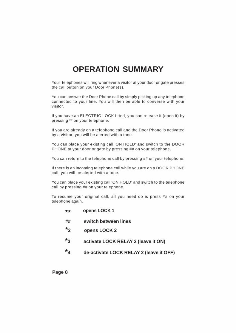
Your telephones will ring whenever a visitor at your door or gate pressesthe call button on your Door Phone(s).
You can answer the Door Phone call by simply picking up any telephoneconnected to your line. You will then be able to converse with yourvisitor.
If you have an ELECTRIC LOCK fitted, you can release it (open it) bypressing ** on your telephone.
If you are already on a telephone call and the Door Phone is activatedby a visitor, you will be alerted with a tone.
You can place your existing call 'ON HOLD' and switch to the DOORPHONE at your door or gate by pressing ## on your telephone.
You can return to the telephone call by pressing ## on your telephone.
If there is an incoming telephone call while you are on a DOOR PHONEcall, you will be alerted with a tone.
You can place your existing call 'ON HOLD' and switch to the telephonecall by pressing ## on your telephone.
To resume your original call, all you need do is press ## on yourtelephone again.
** opens LOCK 1
## switch between lines
*2 opens LOCK 2
*3 activate LOCK RELAY 2 (leave it ON)
*4 de-activate LOCK RELAY 2 (leave it OFF)

Page 9
Pow
er S
uppl
y
Doo
r Gat
e Lo
ck(N
ot S
uppl
ied)
12 V
olt O
ut
12 V
olt I
nO
rang
e
Red
Blac
k
Yello
w
Gre
en
Brow
n
Blue
Whi
te
Tele
phon
e Lin
e In
To A
ll Te
leph
ones
AD
SL F
ilter
(if u
sing
ADSL
)
Tele
phon
e Li
ne O
ut
Seco
nd R
elay
can
con
trol
a se
cond
Loc
kor
an
alte
rnat
ive
devi
ce su
ch a
s a c
amer
a,di
spla
y or
hom
e au
tom
atio
n eq
uipm
ent.
DUAL LOCK DS6 INSTALLATION

Page 10
INSTALLATION WHEN USED WITHA CORDLESS PHONE SYSTEM
The following instruction apply to all users that will use a Cordless PhoneBase station where ALL telephones used operate via the base station, orwhere ALL Telephones are connected direct to the Line Out port of DS6.
Where at least 1 telephone will be connected to a separate telephone socketto that of DS6, then you should follow the installation instructions on pages12-13.
1) Refer to the Diagram on page 11.
2) Connect the LINE INPUT port of DS6 to ANY convenient telephone socketion your line, using the supplied telephone cable fitted with a male plug.
3) Connect the LINE OUTPUT port of DS6 to your Cordless Phone BaseStation, using the supplied telephone cable.
4) Connect the supplied 12V power adaptor to DS6, and switch the POWERON.
5) Connect the SUPPLIED DOOR PHONE to the DOOR PHONE PORT ofDS6. See page 14 for important details.
For convenience, an interface unit with screw terminals is supplied andshould be connected to the DOOR PHONE PORT using the supplied RJ toRJ cable.
Please refer to your Door Phone User Guide
Run a solid core telephone cable (preferably CAT5) between the interfaceunit and the Door Phone.
Our DP1 Door Phone requires only 2 wires.Our DP2-DP5 Door Phones require 4 wires.LOCK 1 (if fitted) will require 2 wires.LOCK 2 (if fitted) will require 2 wires.
6) Fitting your Door Phone to your Wall or Pole surface (see page 14).
7) Test your Door Phone to Telephone communication. If the Audio quality isnot clear in both directions, you may need to adjust the Door Phone BalancePot, as detailed on page 15.

Page 11
INSTALLATION WHEN USED WITHA CORDLESS PHONE SYSTEM

Page 12
INSTALLATION ON FIRST SOCKETWhere you will operate telephones connected to more than 1 telephonesocket, an ACMA approved installation technician will need to fit yourDS6 direct onto your incoming telephone line, immediately ahead ofyour first telephone socket, so that your telephone line connects to allof your telephone sockets through it.
DS6 has been designed so that it will not interfere with the normal useof your telephone line in any way. In the event of a malfunction or powercut, your telephone line will continue to operate.
NOTE - For operation of DS6 on a telephone line fitted with theADSL service, please refer to page 18.
The following instructions describe a typical installation procedure forfitting DS6 to an ordinary telephone line. Alternative methods whichprovide for INCOMING TELEPHONE LINE connection to the LINE INport of DS6, connection of all extension telephones to the LINE OUTport of DS6 and connection of the DOOR PHONE to the DOOR PHONEport of DS6, may be used by a suitably qualified installation technician.
INSTALLATION INSTRUCTIONS
1) Your DS6 unit must be fitted inside the home or office. It mustnot be fitted outside, next to the Door Phone.Fit a NEW 611 TYPE telephone socket next to the ORIGINAL firsttelephone socket. It is best to use a TYPE 611 socket instead of thenormal TYPE 610, as this socket contains switching contacts thatwill automatically reconnect the ORIGINAL telephone socket to theincoming telephone line, should the cable to the DS6 Controller everbe disconnected. (A double telephone socket which containsswitching contacts can also be used in lieu of separate sockets).This NEW 611 socket should be labelled DS6 ONLY. No other devicesshould be connected to this socket. If a normal telephone is to beused at this location, it should be connected to the ORIGINAL firsttelephone socket, along with the LINE OUT port of DS6, using anormal Double Telephone adaptor.

Page 13
2) Transfer the incoming telephone line (normally a BLACK CABLE)from the ORIGINAL first telephone socket to the correspondingpositions 2 & 6 on the NEW telephone socket. Leave all othertelephone cables connected to the ORIGINAL socket, as these arethe connections to your EXTENSION telephones.
3 ) Now connect pins 1 & 5 of the NEW TYPE 611 socket to pins 2 & 6of the ORIGINAL telephone socket. By doing so, the incomingtelephone line will be automatically reconnected to the ORIGINALtelephone should the cable to DS6 ever be disconnected.
4 ) Connect the LINE INPUT port of DS6 to the NEW TYPE 611telephone socket, using the supplied telephone cable fitted with amale plug.
5 ) Connect the LINE OUTPUT port of DS6 to the ORIGINAL telephonesocket, using the supplied telephone cable fitted with a male plug.
6 ) Connect the supplied 12V power adaptor to DS6, and switch thePOWER ON.
7 ) Connect the SUPPLIED DOOR PHONE to the DOOR PHONE PORTof DS6. See page 14 for important details.
For convenience, an interface unit with screw terminals is suppliedand should be connected to the DOOR PHONE PORT using thesupplied RJ to RJ cable.
Run a solid core telephone cable (preferably CAT5) between theinterface unit and the Door Phone.
Our DP1 Door Phone requires only 2 wires.Our DP2-DP5 Door Phones require 4 wires.LOCK 1 (if fitted) will require 2 wires.LOCK 2 (if fitted) will require 2 wires.
Please refer to your Door Phone User Guide
8 ) Fitting your Door Phone to your Wall or Pole surface (see page 14).
9 ) Test your Door Phone to Telephone communication. If the Audio qualityis not clear in both directions, you may need to adjust the DoorPhone Balance Pot, as detailed on page 15.

Page 14
CONNECTING THE DOOR PHONEDP1 DOOR PHONE
Connect the two wires that are connected to the CENTRE 2 PINS of the 8 pinRJ45 socket of DS6, to the screw terminals located on the back of the DOORPHONE. Polarity is not important.
If you plan to use the interface unit, then the terminals for the GREEN andRED wires should be connected to the screw terminals located on the back ofthe DOOR PHONE. Polarity is not important.
The LED on the DOOR PHONE should turn ON (DS6 must be ON).
The DOOR PHONE should be mounted onto your wall surface. With DP1 thisis done by separating the Door Phone unit from the integral backing plate,secured by a screw underneath the grey plastic label, above the speaker. Thebacking plate should then be screwed to the wall surface, before re-attachingthe Door Phone with the securing screw.
DP2-DP5 DOOR PHONESAudio Connection - Connect Pins 4 & 5 (the centre 2 pins) of the 8 pin RJ45socket of DS6 to the centre 2 inputs of the supplied 4 position Phoenix Plug.Polarity is not important.
If you plan to use the interface unit, then the terminals for the GREEN andRED wires should be connected to the centre 2 positions of the 4 positionPhoenix Plug. Polarity is not important.
Power Connection - Connect Pins 3 & 6 (the 2 pins either side of the centre 2pins) of the 8 pin RJ45 socket of DS6, to the outside positions of the 4 positionPhoenix Plug. Polarity is not important
If you plan to use the interface unit, then the terminals for the YELLOW andBLACK wires should be connected to the outside positions of the 4 positionPhoenix Plug. Polarity is not important.
The LED on the DOOR PHONE should now turn ON (DS6 must be ON).
Your DP2-DP5 unit should be screwed direct to the wall with the 2 suppliedmounting screws, or to the optional Surface Mounting Kit.

Page 15
BALANCE POT ADJUSTMENTYour DOOR PHONE is preset at the factory for maximum performance. Oursophisticated circuitry is designed to measure the background noise presentat your site and then apply maximum gain.
In most cases you SHOULD NOT NEED TO MAKE ANY ADJUSTMENTS.
If you are using Two Door Phones connected in parallel, or there is someambient background noise, you may need to adjust the POT of one or bothDoor Phones to suit your specific site conditions.
The balance POT is provided in case you experience one of the following
• Audio is distorted.• Audio (speech) can only be heard in 1 direction.
Should you encounter one of these problems, you will need to make slowcareful adjustments in one direction or the other until speech can be heard inboth directions and without distortion.
The balance POT is accessed via a small hole on the back of the DOORPHONE. You will need to use a small flat blade screwdriver to adjust it.
On Models DP 2-5, the balance POT is located under a small plastic sealingplug, which will need to be temporarily removed.
IMPORTANT NOTES :
1) You will require TWO PEOPLE to adjust your Door Phone.
2) Wait for 10 seconds after answering before adjusting POT.
3) Do not use a telephone IN CLOSE PROXIMITY TO THEDOOR PHONE, as feedback interference will affect theBalance Pot settings. Move at least 3m from the Door Phone.
4) The Balance POT does not increase volume.
Moving it when unnecessary may cause a deteriorationin audio quality or a loss of audio in 1 direction.

Page 16
LOCK CONTROLYour DS6 is provided with TWO internally fitted relays which can be used tocontrol TWO LOCKS or ONE LOCK and ONE OTHER DEVICE such as aVideo Camera, Recorder or Light.
Relay Specification - Dry Relay Contacts rated at 12V/1Amp.
Do not use the supplied DS6 Controller 12V plug pack to also provide12V power for the lock, as this may cause damage to DS6.
You must use a separate 12V source, with a maximum rating of 12V/1A.
LOCK 1 FACILITY
To OPEN the Door/Gate Lock after answering a call from your DOOR PHONEyou need to press ** on your telephone. The lock will remain open for 10seconds (Default setting). It can be sert from 01-99 secs.
Your Door/Gate Lock can also be OPENED at any time by picking up anytelephone and dialling ** . The Door/Gate Lock will remain UNLOCKED for 10seconds (can be 01-99 secs).
You do not need to receive a call from the Door Phone first.
LOCK 2 FACILITYTo OPEN the ALTERNATIVE Door/Gate Lock after answering a call from yourDOOR PHONE you need to press *2 on your telephone. The lock will remainopen until you HANG UP your telephone.
Your ALTERNATIVE Door/Gate Lock can also be OPENED at any time bypicking up any telephone and dialling *2. The Door/Gate Lock will be LOCKEDas soon as you hang up. You do not need to receive a call from the Door Phonefirst.
With the LOCK 2 facility, you can also press *3 and then HANG UP at anytime, which will CLOSE the Internal Relay and leave it closed.
You can then press *4 and then HANG UP at any time, which will OPEN theInternal Relay and leave it open.

Page 17
LOCK INSTALLATIONThe contacts of each Internal relay of DS6 are accessed by the suppliedconnection box. Both DS6 Relays are Dry Contact Relays rated at 12V/1A.The polarity of the Relay connection wires is not important.
Lock 1 should connect to Brown and Orange terminals.
Lock 2 or Device 2 should connect to Blue and White terminals.
NOTE- Do not use the supplied DS6 Controller 12V plug pack to alsoprovide 12V power for the lock, as this may cause damage to DS6. Youmust use a separate 12V source, with a maximum rating of 12V/1A.
If problems are experienced, please refer to page 29 for troubleshootingtips.
LOCK 1Brown and Orange
12 Volt Out
12 Volt InOrange
Red
Black
Yellow
Green
LightCameraSecond Lock
Brown
Blue
Whiteor or
LOCK 2 / Device 2Blue and White

Page 18
USERS WITH ADSLDS6 can be used with ADSL on the same telephone line.
However it is ESSENTIAL to fit a SINGLE High Quality ADSL filterimmediately ahead of the DS6 Controller. Failure to do so, or use ofadditional ADSL filters connected direct to your telephones, WILL causeproblems in the operation of your DS6 Controller and ADSL service.
Please Note - Basic ADSL FILTERS, designed for separate connectionto each telephone on your line (as usually supplied with ADSL modems)are not suitable.
We recommend the use of the C10 Brand ADSL Filters.
Model C10-1 (P/N C10245M), is suitable for sites with 3 or less telephonedevices connected to the line . RRP is : $35.00 incl GST.
Model C10-2 (P/N C10100E), is suitable for sites with 4 or more telephonedevices connected to the line . RRP is : $65.00 incl GST.
USERS WITH DIAL OUT ALARMSDS6 can be used with a DIAL OUT SECURITY ALARM on the sametelephone line.
However to avoid conflict, it is ESSENTIAL to fit the DIAL OUT SECURITYALARM on the telephone line AHEAD of the DS6 unit, using a MODE 3switch.
If ADSL is also to be used on this same line, then it is ESSENTIAL to fita single High Quality ADSL filter immediately ahead of the MODE 3Switch, being the first point on the telephone line.
This means that the Security Alarm, DS6 Line Sharer and all telephonesconnected on the telephone line have adequate filtering from the highfrequency ADSL communication.

Page 19
HANG UP AFTER DIAL OUTDS6 incorporates a HANG UP TONE DETECTOR which is designed todetect ‘Australian’ specification hang up tones, that will be present whenDS6 has made an outgoing call to a programmed Cell Phone or ExternalNumber after the completion of the call. This process is fully automatic.
When installed on PABX systems, the Hang Up tone generated may beoutside of the cadence and frequency normally used in Australia for HangUp tones. In this situation, DS6 may not hang up until the Maximum DoorPhone Call Time has elapsed. Our Hang Up detector, looks for :
1. A Tone Frequency between 200Hz and 600Hz.2. A Tone Duration between 300mS and 600mS.3. A 50% Duty Cycle +/- 20%
(ie ON and OFF periods should be the same +/- 20%)
You can adjust your PABX system to generate Hang Up tones as per theabove specification, or to output normal Australian Hang Up tones.
ORYou can PRESS ANY TOUCH TONE NUMBER digit (0 to 9) on your telephoneto cause an immediate disconnection of the call.
AND/ORYou can set the Maximum Door Phone Call Time to a time less than 99seconds but which is still long enough to communicate with your visitors.DS6 will terminate all Door Phone calls at this time setting.
ELECTRO MAGNETIC INTERFERENCE
At some sites, Electro Magnetic Interference often caused by NoisySwitch Mode power supplies can result in DS6 not always being able toreliably detect these tones. DS6 may not hang up until the MaximumDoor Phone Call Time has elapsed. Should this occur, you can overcomethe problem by moving the offending switch mode power supply awayfrom the DS6 and its conventional power supply. The distance to bemoved, will depend on the level of noise generated and will need to bedetermined by trial and error.
IMPORTANT NOTEImmediate Hang Up can also be achieved by simply pressing ANYTouch Tone Number key (0 to 9) on your telephone at the end of acall. Important Note : # and * cannot be used for this function.

Page 20
MULTI-LINE TELEPHONE SYSTEM USEOur DS6 Line Sharer can be fitted in one of 3 ways :
1) ON A SPECIFIC LINE
See Diagram 1 on page 21
DS6 can be fitted to ONE SPECIFIC INCOMING LINE of a Multi Line PABXtype system. In this situation, the incoming telephone line, prior to thesystem controller should be connected to the LINE IN port of the DS6Controller and the LINE OUT port of the DS6 Controller should then beconnected to the system controller.
Once fitted, the system will operate exactly as described previously, foroperation on the selected line.
2) ON AN UNUSED TRUNK LINE
See Diagram 2 on page 21
DS6 can also be fitted to an UNUSED TRUNK PORT or UNUSED LINEPORT of ANY Multi Line Telephone System.
This means that this particular line WILL ONLY RING when the Door Phonehas been activated. In this situation, the LINE OUT port is the only connectionto the system controller.
An incoming telephone line connection (or talk battery) is not required.
3) ON A PABX ANALOGUE EXTENSION
DS6 can also be fitted to an :
*** ANALOGUE EXTENSION of a conventional Phone System.OR*** FXS PORT of an IP Phone SYSTEM.
See pages 22-23
Page 21
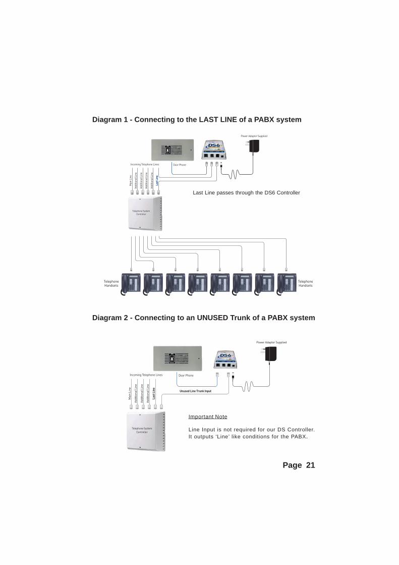
Diagram 1 - Connecting to the LAST LINE of a PABX system
Diagram 2 - Connecting to an UNUSED Trunk of a PABX system
Important Note
Line Input is not required for our DS Controller.It outputs ‘Line’ like conditions for the PABX.
Last Line passes through the DS6 Controller

Page 22
CONNECTING TO PABX ANALOGUE EXTENSION
OR ATA or FXS PORT OF IP PHONE SYSTEM
DS6 can also be connected to an ANALOGUE EXTENSION, ATA or FXSPORT of ANY Multi-Line telephone system.
It can operate in 2 ways :
1) It can be used with a PABX Extension which is set up to HOTDIAL.This is the most commonly used manner. If you plan to you is in this way,you MUST program it to do so as follows :
a) Enter Programming Mode (see pages 26-27)
b) When in Programming Mode, Enter 003
c) Hang Up after you hear the Single Confirmation Tone.
This sets DS6 to operate like a DS5, where it will go off hook when triggeredby the Door Phone. DS6 will terminate the Intercom call upon detection ofAustralian Specification Hang Up Tones, when the answering phone is hungup. It can also termnate the call after the Max Call Time setting has beenmet OR if the answering party presses ANY DTMF Digit from 0-9.
2) It can be set to DIAL OUT a pre-programmed NumberIf you operate DS6 in this manner you MUST program it to:
DIAL a user programmed telephone number or extension whenactivated by the call button of the supplied Door Phone.
a) Enter Programming Mode (see pages 26-27)
b) When in Programming Mode, Enter **xxxxxxxxxx**xxxxxxxxxx = the number you require DS6 to Dial. You must enter **before and after this number.
c) Hang Up after you hear the Single Confirmation Tone.
d) Set DS6 to Dial Out Immediately by pressing #1 on ANY telephoneconnected to the Line Out Port (see page 7 - #1 Mode).

Page 23
CONNECTING TO PABX ANALOGUE EXTENSION
OR ATA or FXS PORT OF IP PHONE SYSTEM

Page 24
PROGRAMMING OPTIONSA number of features are provided to allow you to customize the capabilityof this device to meet individual requirements. DS6 will retain yoursettings even if power is disconnected.
DOOR PHONE CALL ADVICE TONES5 shorts ‘beeps’ can be injected into the Door Phone call, immediatelyafter answer, to advise you that the incoming call has originatedfrom your Door Station. This facility is very useful for those userswho may use cordless phones, that do not ring differently when thereis a Door Phone call.
Allowable Range : ON or OFFDefault Setting is : OFF
MAXIMUM DOOR PHONE CALL TIMEYour DS6 unit has been pre-programmed to detect Australian ‘HangUp’ tones to determine when the call is complete and to terminatethe call connection. Due to the possibility that your equipment maynot generate ‘Hang Up’ tones or suitable tones, a maximum allowabletime limit is set for a Door Phone call.
Allowable Range : 15 to 99 secondsDefault Setting is : 99 seconds
NUMBER OF RINGS before stopping or DIAL OUTDS6 will ring your telephones 10 times when it is triggered by a DoorPhone call. This can be changed from 1-99 rings. DS6 has the abilityto DIAL OUT to an external telephone number or mobile number, ifthe call is unanswered after the programmed NUMBER OF RINGS.
Allowable Range : 1 to 99 ringsDefault Setting is : 10 rings
RING OUTPUT PATTERNYour DS unit outputs a SINGLE 1 second repeating ring pattern whenit is activated by the attached Door Phone. You can alternativelyprogram DS6 to output TWO 1 second rings, THREE 1 second ringsor FOUR 1 second repeating rings. This feature is useful when youplan to use more than ONE DS unit on your line as this will alloweach unit to generate a different ring pattern .
Allowable Range : 1 to 4 repeating ringsDefault Setting is : 1 repeating ring

Page 25
PROGRAMMING OPTIONSLOCK 1 TIME OUT
The first lock control facility should be used to open a gate or lock.You can set the time which LOCK 1 will remain open after the userpresses the ** command, between 01-99 seconds.
01 to 99 is the time interval that the LOCK REMAINS OPEN afterpressing **
Allowable Range : 01 to 99Default Setting is : 10
LOCK 2 TIME OUT
The second lock control facility can be used for either :
A SECOND alternative Gate or Door LOCKorTo SWITCH ON and OFF a VIDEO DEVICE or a LIGHT.orTo alert a HOME AUTOMATION SYSTEM of a visitor
If a separate Lock is fitted, set this command to : 00.Press *2 - Lock 2 will remain OPEN until you hang up the Phone.
If a Video Device, Light or Home Automation System is fitted at theDoor or Gate), set this command to : 01 to 99.
01 to 99 is the time interval in seconds that the DEVICE REMAINS ONafter the Door Phone call is complete.
Allowable Range : 00 to 99Default Setting is : 0 0
DIAL OUT DELAYDS6 waits 2 seconds before dialing. When DS6 is used on somePABX systems, this may not be long enough to obtain dial tone viathe PABX. The Dial Out Delay can be increased to 6.5 seconds.
Allowable Range : 2.0 to 6.5 secondsDefault Setting is : 2.0 seconds

Page 26
RESET FACTORY DEFAULTSWith our latest models, all programming parameters of DS6 can be reset backto the DEFAULT SETTINGS (as detailed on pages 24-25) by entering 13579while in the Programming Mode.
REMOTE PROGRAMMINGWith our latest models, you can now program DS6 Controller functions via atelephone call from a remote location.
To enter Programming Mode via a Remote Number or a Cell Phone :
1) Dial the site (or extension) number2) Press 12345 once the call has been answered.3) Follow instructions 4 A-I as per pages 27-28.4) Hang Up when finished.
PROGRAMMING NOTESThe following notes provide important information about the programmingprocedure :
1) To enter PROGRAMMING MODE you must turn OFF POWER toyour unit and then switch POWER ON AGAIN.
2) Using ANY TELEPHONE connected to DS6, PRESS # within 30seconds. If your DS6 is not connected to a telephone line, then youmust insert the supplied ‘RJ12 Looping Plug’ into the Line In port.
3)You will hear 3 short ‘beeps’ to confirm you are in programming mode.
4) Individual Parameter Programming Entries are also carried out bypressing further keys on the attached telephone.
5) Your unit will generate 1 short ‘beep’ to confirm acceptance ofcommand.
6) Your unit will generate 1 long ‘beep’ to advise of an entry error.
IMPORTANT NOTENote - After each power up DS6 will prepare to enter programmingmode for 30 seconds. During this time, dial tone is not available.You can cancel out of this mode (before the 30 second limit) andachieve dial tone by Hook Flashing, Hanging Up OR pressing anyDTMF Touch Tone digit other than #.
Page 27
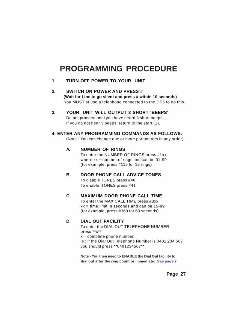
PROGRAMMING PROCEDURE1. TURN OFF POWER TO YOUR UNIT
2. SWITCH ON POWER AND PRESS # (Wait for Line to go silent and press # within 10 seconds) You MUST st use a telephone connected to the DS6 to do this.
3. YOUR UNIT WILL OUTPUT 3 SHORT ‘BEEPS’Do not proceed until you have heard 3 short beeps.If you do not hear 3 beeps, return to the start (1).
4. ENTER ANY PROGRAMMING COMMANDS AS FOLLOWS:(Note - You can change one or more parameters in any order)
A. NUMBER OF RINGSTo enter the NUMBER OF RINGS press #1xxwhere xx = number of rings and can be 01-99(for example, press #115 for 15 rings)
B. DOOR PHONE CALL ADVICE TONESTo disable TONES press #40To enable TONES press #41
C. MAXIMUM DOOR PHONE CALL TIMETo enter the MAX CALL TIME press #3xxxx = time limit in seconds and can be 15-99(for example, press #360 for 60 seconds)
D. DIAL OUT FACILITYTo enter the DIAL OUT TELEPHONE NUMBERpress **x**x = complete phone number.ie : if the Dial Out Telephone Number is 0401 234 567you should press **0401234567**
Note - You then need to ENABLE the Dial Out facility to dial out after the ring count or immediate. See page 7

E. RING OUTPUT PATTERNTo select a different Repeating Ring Output : press #8x
x = number of repeat rings before pausingIt can be set from 1-4 (repeating rings)(for example, press #83 for 3 repeating rings)
F. LOCK 1 SET UPTo enter the LOCK 1 OPEN TIME press #6xx
xx = time limit in seconds that LOCK 1 will remain openafter pressing **. It can be set from 01-99 (seconds)(for example, press #630 for 30 seconds)
G. LOCK 2 SET UP
To set LOCK 2 to control a SECOND LOCKpress #200To set LOCK 2 to SWITCH ON/OFF a device press #2xx
xx = time limit in seconds that attached device remains ON after hang up.
xx = can be set from 01-99 (seconds) (for example, press #230 for 30 seconds)
H. DIAL OUT DELAYTo increase the DIAL OUT DELAY press #5xx = Dial Out Delay in seconds
If x = 0 - delay is 2.0 seconds If x = 5 - delay is 4.5 secondsIf x = 1 - delay is 2.5 seconds If x = 6 - delay is 5.0 secondsIf x = 2 - delay is 3.0 seconds If x = 7 - delay is 5.5 secondsIf x = 3 - delay is 3.5 seconds If x = 8 - delay is 6.0 secondsIf x = 4 - delay is 4.0 seconds If x = 9 - delay is 6.5 seconds
I. RESET TO FACTORY DEFAULT SETTINGSTo RESET to Factory Defaults, press 13579
TO EXIT PROGRAMMING MODE - HANG UP.
ALL ENTRIES ARE SAVED IN PERMANENT MEMORY.
Page 28

Page 29
TROUBLESHOOTING LOCK CONTROLBoth DS6 Relays are Dry Contact Relays rated at 12V/1A.
If you are having trouble controlling the LOCK or GATE STRIKE,please trouble shoot by using the following procedure :
1. Test that you receive the correct voltage across the terminals of the suppliedconnection box, when ** or *2 is pressed on the attached telephone.
Lock 1 should connect to Brown and Orange terminals.
Lock 2 device should connect to Blue and White terminals.
2. If the correct voltages are not present investigate all wiring to and from yourlock and power source.
3. If the correct voltage is present, short across the two terminals and yourelectric lock should operate.
If your lock still does not operate, there will be a problem with wiring betweenyour power supply, electric lock and connection box.
If your lock operates, then the problem is located in the wires of theconnection box, the RJ to RJ lead connecting to the DS6 unit or the relaywithin the DS6 unit itself. If possible, please bypass the connection box andthe RJ to RJ lead connecting to the DS6 unit by feeding the two powersupply wires of the electric lock into an RJ45 plug in positions 2 & 7 (Lock 1)and 1 & 8 (Lock 2).
If the lock then works with ** or *2, then the problem is in the connection boxor the RJ to RJ lead connecting to the DS6 unit.
If the lock still does not work with **, then the problem may be within theDS6 unit, or interference is preventing DS6 from detecting the ** command.
4. ADSL Interference or Electromagnetic Interference (EMI) caused by SwitchMode Power Supplies or Uninterruptable Power Supplies can prevent the **touch tones from being detected by DS6.
5. Follow the instructions in section 3 on page 30.
6. If your problem is still unresolved, please call the number on the frontpage for further assistance.
IMPORTANT NOTE - You must not use the Power Adaptorsupplied with DS6 to power either Door Lock or Strike.

Page 30
TROUBLESHOOTING AUDIOIf you are having trouble with AUDIO COMMUNICATION between theDOOR PHONE and ANY TELEPHONES on your line, please follow theprocedure below.
Most problems are caused by site specific conditions. Through a processof elimination, the source of problems can be determined and then rectified.
1. If you use ADSL on your telephone line, ensure that you have a HighQuality ADSL2+ filter fitted to your telephone line ahead of the DS6 Controller.
If you have recently updated your ADSL service, your old filter is unlikely tobe compatible with your new service, as ADSL2+ requires different filteringto the ADSL2 service or the original ADSL1 service. To ensure that youhave correct filtering, we recommend the use of the C10 brand filters, asdescribed on page 18.
2. Your BALANCE POT, located on the back of the Door Phone may needadjusting as described on page 15.
3. If you are still having audio quality problems, they can be caused by EMI(Electro Magnetic Interference) from some Switch Mode Power Suppliesand some low end UPS units (Uninterruptable Power Supplies).
Switch Mode Power Supplies can be easily identified because they arevery light, due to the fact that they do not use a transformer. Many brandsof the these power supplies are well known to generate high levels of EMI.
Please TURN OFF any SWITCH MODE POWER SUPPLIES locatednear the DS6 controller (and its power supply) and test if theproblem is resolved.
If the DS6 Power Supply is connected to an UninterruptablePower Supply, remove it and test if the problem is resolved.
4. If you are still having audio quality problems, then you may be pickingup interference (50hz power or other interference) from the telephone lineinput, or the cable leading to your Door Phone.
To test for this, you need to temporarily isolate our equipment from theexisting devices/cable, using the following procedure :

Page 31
TROUBLESHOOTING AUDIOContinued.
5. Disconnect the telephone cable from the LINE OUT port of your unit andconnect a single corded telephone into this port. Now test communicationwith this single phone.
If satisfactory operation can be achieved, you should fault find your problemwith the wiring or telephones downstream of our unit by connecting them toour unit 1 device at a time.
6. If satisfactory operation cannot be achieved, you should disconnect thetelephone cable from the DOOR PHONE port of your DS6 unit andtemporarily run NEW CAT5 cable from the DS6 to your DOOR PHONE.
Alternatively, you can remove the Door Phone from its normal position andmove it closer to the DS6 unit so that you can connect it using a temporarynew CAT5 cable. Please ensure this temporary test cable is no less than 3meters away from your DS6 unit in order to prevent Audio Feedback.
If satisfactory operation can be achieved, you should fault find your problemin the wiring leading to the DOOR PHONE unit.
7. If satisfactory operation cannot be achieved, you should disconnect thetelephone line input to the LINE IN port of your DS6 unit. (Note : with thetelephone line disconnected, audio communication can be achieved, butDTMF operation will not work).
If satisfactory operation can be achieved, you should fault find your problemcaused by the incoming telephone line. If you are using ADSL, ensure thatyou are using a high quality filter such as the C10 Brand, models C10245Eor C10100E. These devices are available from your Dealer or NationalCommunications. See page 18 for more detail.
8. If your problem is still unresolved, please call the number on the frontpage for further assistance.

SPECIFICATIONS
Dimensions (all in mm) : 106(W) x 106(D) x 43(H)Weight : 225gPower Supply : 12VAC/500mAPower Consumption : Idle - 0.5 WattsPower Consumption : Call - 0.75 WattsTelephone Line In Connector : RJ 11 6 pin (2 centre)Telephone Line Out Connector: RJ 11 6 pin (2 centre)Door Phone Connector : RJ 45 8 pin (2 centre)Door Phone Connector (Lock 1): RJ 45 8 pin (pins 2 & 7)Door Phone Connector (Lock2 ): RJ 45 8 pin (pins 1 & 8)Power Connector : 2.5mm barrel connectorACMA COMPLIANT : Supplier Number N 782
WARRANTY
This device is guaranteed against defects from workmanship for a periodof two years (24 months) from the date of purchase. In the event offailure, you should return the product, along with proof of purchase date,and a written statement about the nature of the problem.
This Warranty shall not apply to any unit which has been subject toalteration, modification, abuse, negligence, accident, external voltage/lightning surge or used in any manner contrary to these instructions.
The obligation is solely to repair or replace the product. The warrantoris not liable for any incidental or consequential damages due to suchdefects.
The user is responsible for freight costs to the repair point. The warrantorwill be responsible for freight costs in returning this unit back to theuser.
Damage caused to this device or attached equipment, by lightning strikesor over voltage surge is not covered under this warranty.
CASE SEALED AT FACTORYOPENING THE CASE VOIDS THE WARRANTY
Page 32 s