telescopic steel covers - idium.no steel covers standard products ... - firstly it has a solid metal...
TRANSCRIPT

1
TELESCOPIC STEEL COVERS
Standard products
w w w . p e i . e u
Rep
rod
uct
ion
of
this
pa
ge
is s
tric
tly
pro
hib
ited
.
Telescopic Steel Covers
There are many companies throughout the world who manufacture or sell Telescopic Steel Covers. Our company has
achieved production levels - in terms of volume and quality standards - that place it at the top of the market.
Heavy investment in machinery and personnel training, under the guidance of highly qualified engineers have allowed us to
face the latest challenge in the development of Machine Tools: the increase of the axis speeds.
For high speeds, P.E.I. shock absorbers
(patented) are inserted in these positions.
They are very effective in reducing impact
between boxes during movement.
These shock absorbers allow working speeds
considerably higher than those previously
possible, while simultaneously reducing
noise levels and wear.
This innovation, together with precision
production methods, make it possible to
accomodate even the fastest machine
tools.
Special anti-friction brass guides
or wipers with polyurethane rubber
are inserted on the sides of the Telescopic Steel
Covers, at the discretion of the engineer
based on speed, seal and dimensions.
Wipers keep the surface clean
and prevent chips and
shavings from getting onto
expensive rails.
They must be heat and coolant
resistant, and thus are made of
polyurethane, with or without
a protective stainless steel chip guard.
For high speeds
or weights, special
bearings are inserted
for smooth, silent
movement.
Telescopic Steel Covers
with bearings require
tempered or auxiliary
guides.
Compact, low-speed
Telescopic Steel Covers are
equipped
with special
anti-friction brass
or non-metallic
guides.
For heavy covers:
a) over 110 kg
for horizontal covers
b) over 70 kg
for front or vertical covers.
Special supports are included
for easy, secure lifting.
The steel used is extremely high quality
in terms of flatness, corrosion resistance
and wear resistance.
Thickness ranges from 1.5 to 3 mm.
Telescopic Steel Covers
may also be made
of stainless steel.

2
TELESCOPIC STEEL COVERS
Standard products
w w w . p e i . e u
Rep
rod
uct
ion
of
this
pa
ge
is s
tric
tly
pro
hib
ited
.
Horizontal position Vertical position
Transverse position
Cover gathered on extensions or support flanges,
if desiredRemovable
closing panelif desired
Transverse LATHE cover
Snap-on guides available upon request for rapid frontal
installation
Profiled guides for
secure fastening
Working Positions

3
TELESCOPIC STEEL COVERS
Standard products
w w w . p e i . e u
Rep
rod
uct
ion
of
this
pa
ge
is s
tric
tly
pro
hib
ited
.
Configurations
Shape 1
Shape 3
Shape 5
Shape 2
Shape 6
NOTE: Only a few standard configurations of Telescopic
Steel Covers are shown above.
Shape 4
Closed Length Stroke
Open Length
Closed Length
4
TELESCOPIC STEEL COVERS
Standard products
w w w . p e i . e u
Rep
rod
uct
ion
of
this
pa
ge
is s
tric
tly
pro
hib
ited
.
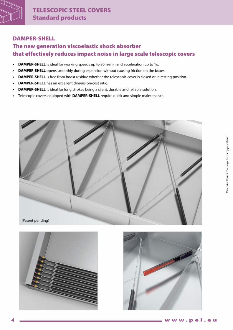
DAMPER-SHELL
The new generation viscoelastic shock absorber
that effectively reduces impact noise in large scale telescopic covers
• DAMPER-SHELL is ideal for working speeds up to 80m/min and acceleration up to 1g.
• DAMPER-SHELL opens smoothly during expansion without causing friction on the boxes.
• DAMPER-SHELL is free from boost residue whether the telescopic cover is closed or in resting position.
• DAMPER-SHELL has an excellent dimension/cost ratio.
• DAMPER-SHELL is ideal for long strokes being a silent, durable and reliable solution.
• Telescopic covers equipped with DAMPER-SHELL require quick and simple maintenance.
(Patent pending)
5
TELESCOPIC STEEL COVERS
Standard products
w w w . p e i . e u
Rep
rod
uct
ion
of
this
pa
ge
is s
tric
tly
pro
hib
ited
.
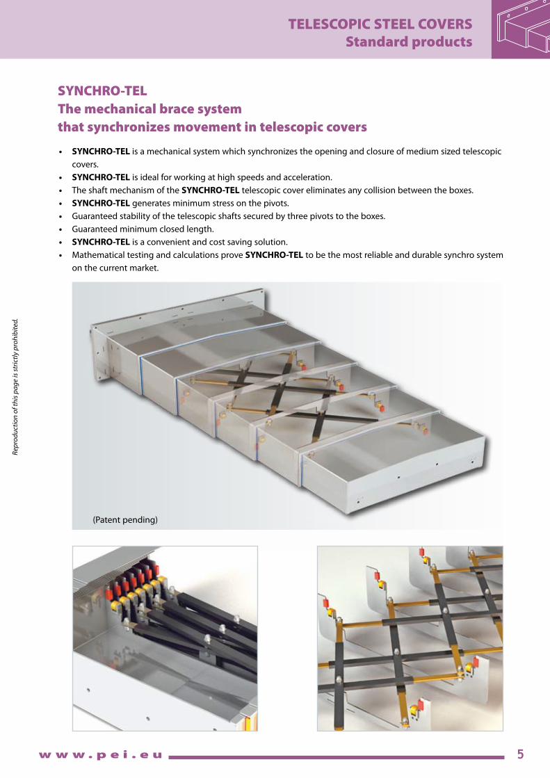
SYNCHRO-TEL
The mechanical brace system
that synchronizes movement in telescopic covers
• SYNCHRO-TELis a mechanical system which synchronizes the opening and closure of medium sized telescopic
covers.
• SYNCHRO-TEL is ideal for working at high speeds and acceleration.
• The shaft mechanism of the SYNCHRO-TEL telescopic cover eliminates any collision between the boxes.
• SYNCHRO-TEL generates minimum stress on the pivots.
• Guaranteed stability of the telescopic shafts secured by three pivots to the boxes.
• Guaranteed minimum closed length.
• SYNCHRO-TEL is a convenient and cost saving solution.
• Mathematical testing and calculations prove SYNCHRO-TEL to be the most reliable and durable synchro system
on the current market.
(Patent pending)

6
TELESCOPIC STEEL COVERS
Standard products
w w w . p e i . e u
Rep
rod
uct
ion
of
this
pa
ge
is s
tric
tly
pro
hib
ited
.
PR4A
The instantly replaceable wiper for Telescopic covers
Attention: dissassembly not required!
• WIPERPR4A is a cutting-edge solution for replacing the wiper profile instantly and without stopping the machinery.
• WIPERPR4A is made of 3 independent elements:
- firstly it has a solid metal profile on the telescopic cover box
- secondly it has a removable metal profile
- finally it has a seal designed to clean the cover.
• Telescopic covers equipped with WIPER PR4A allow the client to independently replace the wiper profile:
- Release the removable part
- Replace the removable metal profile ready-made for the new seal
- WIPER PR4A offers a range of seals with different technical
features depending on the working conditions it is subjected
(e.g. a working environment that uses coolants or a dry working environment in the PR4A D version).
(Patent pending)

8
TELESCOPIC STEEL COVERS
Special products
w w w . p e i . e u
Rep
rod
uct
ion
of
this
pa
ge
is s
tric
tly
pro
hib
ited
.
SHEET-POCkET TM
The SHEET-POCKET TM Telescopic Steel Cover is the most effective solution for shielding the Y-axis (vertical) in horizontal
machining centers. It can achieve speeds up to 150 m/min. and accelerations of 2 g. It is supplied in a fully enclosed
frame that is independent from the machine structure. The self-contained sheet-pocket is easy to install and remove for
maintenance or inspection.
The dimensions are defined by our technicians together with the customer’s engineers to maximize the working area.
Spindle opening
with edges
guarded by
protected wipers,
with
polyurethane
profile.
Telescopic Steel
Cover casing
designed to allow
easy installation
and rapid
disassembly
for maintenance.
The SHEET-POCKET TM Telescopic Steel Cover can be easily combined with SURE-SPRING® roll-up covers as shown on page 16 of this catalog.
(Patented)
Sequence of moving panels,
made of special high-resistance
steel, fully adhering to one another to
prevent shavings from penetrating inside.

9
TELESCOPIC STEEL COVERS
Special products
w w w . p e i . e u
Rep
rod
uct
ion
of
this
pa
ge
is s
tric
tly
pro
hib
ited
.
SQUARE SLIDING COVER TM
This family of Telescopic Steel Cover, was designed to meet special needs that frequently arise on SPECIAL or TRANSFER
machines and small machining centers. This configuration is especially innovative thanks to the patent-pending method
for moving each individual panel, thus allowing users to take greater advantage of the available space.
ROUND SLIDING COVER TM
Like the SQUARE SLIDING COVER, this type of Telescopic Steel Cover was designed to meet special needs that
frequently arise on SPECIAL or TRANSFER machines and small machining centers.
Since it has a wide range of applications, contact our Engineering Department to define the ideal sizing for the cover.
(Patented)
(Patented)
• Fordual-axisoperation
• Highspeed
• Compactsize
• Easytoinstall
• Maximumuseofavailablespace
• Fordual-axisoperation
• Highspeed
• Compactsize
• Easytoinstall

Rep
rod
uct
ion
of
this
pa
ge
is s
tric
tly
pro
hib
ited
.
10
TELESCOPIC STEEL COVERS
Special products
w w w . p e i . e u
Rep
rod
uct
ion
of
this
pa
ge
is s
tric
tly
pro
hib
ited
.
METAL TELESCOPIC COVER REVISION
• OverhaulofALLTYPESoftelescopiccoversformachinetools
• Revisionorreplacementofdamagedsections
• Replaceridersorguiderollers
• Replacebrasswearstrips
• Cleanandbuffedtooriginalfinish
• Incaseoftoodamagedtelescopiccovers,wecanbuildthemnew.
• SHORTDELIVERYTIME
Inspection of
P.E.I. staff
for field surveys
BEFORE
AFTER

11
ROLL-UP COVERS
Standard products
w w w . p e i . e u
Rep
rod
uct
ion
of
this
pa
ge
is s
tric
tly
pro
hib
ited
.
P.E.I. Roll-up Covers are normally equipped with our patented system of multiple springs. This offers countless advantages:
• Reliability • Compactsize
• Extremelyhighspeeds • Easyinstallation
• Resistancetohighandlowtemperatures • Constanttensioning
• 1,000,000movementsguaranteed • Specialroll-upcoversformachinetools
Roll-up Covers
STEEL-TEX
STEEL-TEX: the stainless steel band specially studied for roll-up covers.
• STEEL-TEXisathestainlesssteelroll-upcoverwithpolyurethane.
• STEEL-TEXiscutresistantonimpactwithincandescentandsharpmetalshavings.
• STEEL-TEXoffersexceptionalresistanceduringdryworkingorwithcoolants.
• STEEL-TEXiscompact,weighs0.9kgpersq.mandis0.8mmthick.
• STEEL-TEXcanbeinstalledontheentirerangeofP.E.I.roll-upcovers.
(Patent pending)

12
ROLL-UP COVERS
Standard products
w w w . p e i . e u
Rep
rod
uct
ion
of
this
pa
ge
is s
tric
tly
pro
hib
ited
.
30 6 8 8 2,6 7 8
40-50-60-70 10 15 12 4 10 10 80-90-100-120
Roll-up Covers without Canister
Formula for calculating max. Ø
Ø ROLLER d1 IL FL SL d IP
Shaft sizes
033
050
060
080
119
Code A B C D E F Ø Hmax Material
33 45 26 40 11 18 6,5 59 galvanized Fe 15/10
50 62 26 40 11 18 6,5 93 galvanized Fe 15/10
60 76 36 50 15 22 6,5 112 galvanized Fe 20/10
80 96 42 60 17 26 6,5 151 galvanized Fe 25/10
119 136 54 106 37 70 10 225 galvanized Fe 40/10
L = MAX. LENGTH TO WIND
s = BAND THICKNESS*
r = ROLLER Ø/2
(* see materials list on pages 52-53)
Formula for calculating the
OVERALL WIDTH
Example:
LM = 1000 LT = 500 2Y = 8
OVERALL WIDTH = 508
OVERALLWIDTH=LT+2Y
For special working conditions, our engineering department can adjust these dimensions. Carefully review the drawing enclosed with the proposal.
39-52-71 10 15 12 4 10 10
Ø ROLLER d1 IL FL SL d IP
Standard Roll-up Covers
SURE-SPRING® Roll-up Covers
Measurements for standard supportsØ MAX. = 2 .
L . s . 1,20 + r 2
π
SL
IL
FL
Y Y
d1 d
IP
LM
= M
AX
. LE
NG
TH
LC
= S
TR
OK
E L
EN
GT
H
Ø MAX.
LT= BAND WIDTH
OVERALL WIDTH
RO
LLE
R Ø
D
BA
C ==
F
E
3 2
Ø
MA
X. H
.
2 holes
OVERALL WIDTH
LM2 •Y=
0
401
601
801
1201
1601
2401
3001
3851
4701
4
5
6
8
10
14
18
22
26
32
Da a
400
600
800
1200
1600
2400
3000
3850
4700
5550

13
ROLL-UP COVERS
Standard products
w w w . p e i . e u
Rep
rod
uct
ion
of
this
pa
ge
is s
tric
tly
pro
hib
ited
.
ROLLER Ø30
ROLLER Ø40
ROLLER Ø50
ROLLER Ø60
ROLLER Ø70
ROLLER Ø80
ROLLER Ø90
ROLLER Ø100
ROLLER Ø120
Roll-up Covers with Canister
Enclosing the roller offers many advantages:
• Protectsrollerfromaccidentalimpact • Widevarietyoffasteningsystems
• Integralwiperkeepsbandclean • Materials:Aluminum,Steel,StainlessSteel
• Attractiveappearance • 1,000,000movementsguaranteed
OVERALL WIDTH 150 250 350 500 750 1000 1250 1500
MAX. LENGTH 300 500 650 800 1000 1200 1350 1500
OVERALL WIDTH 150 250 350 500 750 1000 1250 1500
MAX. LENGTH 400 600 900 1200 1500 1800 2000 2200
OVERALL WIDTH 150 250 350 500 750 1000 1250 1500
MAX. LENGTH 450 700 1050 1350 1650 2000 2250 2450
OVERALL WIDTH 150 250 350 500 750 1000 1250 1500
MAX. LENGTH 500 1000 1600 1900 2200 2500 2750 3000
OVERALL WIDTH 150 250 350 500 750 1000 1250 1500
MAX. LENGTH 550 1100 1750 2050 2350 2600 2900 3150
OVERALL WIDTH 150 250 350 500 750 1000 1250 1500
MAX. LENGTH 700 1300 2000 2350 2700 3100 3400 3700
OVERALL WIDTH 150 250 350 500 750 1000 1250 1500
MAX. LENGTH 750 1400 2150 2500 2850 3200 3550 3850
OVERALL WIDTH 150 250 350 500 750 1000 1250 1500
MAX. LENGTH 800 1500 2300 2650 3000 3300 3700 4000
OVERALL WIDTH 150 250 350 500 750 1000 1250 1500
MAX. LENGTH 850 1600 2450 2800 3150 3400 3850 4150
40 x 40
50 x 50
60 x 60
70 x 70
80 x 80
90 x 90
100 x 100
110 x 110
120 x 120
130 x 130
140 x 140
150 x 150
OVERALL WIDTH 250 350 500 750 1000 1250 1500
MAX. LENGTH 850 1250 1650 2000 2500 3000 3850
OVERALL WIDTH 250 350 500 750 1000 1250 1500
MAX. LENGTH 1000 1500 2000 2500 3000 3850 4700
OVERALL WIDTH 250 350 500 750 1000 1250 1500
MAX. LENGTH 1400 2100 2400 2850 3700 4800 5550
ROLLER Ø39
ROLLER Ø52
ROLLER Ø71
Size examples for SURE-SPRING® Roll-up Covers
Canister material K Q Z*
Aluminum 3 1 25
Steel 10 7 13
Stainless steel 10 7 13
Z*= FIXED COEFFICIENT
K Q
A
A= =LT= BAND WIDTH
OVERALL WIDTH MAX. Ø
ROLLER Ø
LM
= M
AX
. LE
NG
TH
LC
= S
TR
OK
E L
EN
GT
H
Canisters
A x A
These tables list the recommended MAX. BAND LENGTH based on the OVERALL WIDTH.
The values shown are guaranteed at a MAX. SPEED of 40 m/min.
For higher speeds and for sizes not indicated in the tables, contact our engineering department
Recommended sizes
All the Roll-up Covers with or without Canister are manufactured to order.
With Steel and Stainless Steel
canister
Formula for calculating
the Minimum
canister size = A
A = MAX Ø + 8
Formula for calculating the
OVERALL WIDTH
Example with Steel canister:
LT= 500 2Y= 8 LM =1000
LM/100 =10 Z= 13
OVERALL WIDTH = 531
(* see 2Y table on page 12)
LT+Z+2Y*+( LM ) 100
OVERALL WIDTH =

14
ROLL-UP COVERS
Standard products
w w w . p e i . e u
Rep
rod
uct
ion
of
this
pa
ge
is s
tric
tly
pro
hib
ited
.
Installing Roll-up CoversThis diagram is valid for all Roll-up Covers, and shows:
• Terminaltype • Bandoutputdirection
• Terminalpositionontheband • Viewofshaft/tab
Horizontal and frontal positions Vertical positions
Terminal materials: Aluminum, Steel
Standard canister mounting systems: To describe the canister attachment system, place one of the drawings below over the selected roll-up cover position, above. Do not rotate either drawing.
Working positionTerminal attachmentCanister attachmentWiper position
Positions Wiper: This diagram shows the 2 ways to install the wiper to the canister.
F1
2
T5
R2
Visible side
R1
R2
Visible side
Visible side
Example assembling code
Horizontal
Frontal
Vertical

16
ROLL-UP COVERS
Special Products
w w w . p e i . e u
Rep
rod
uct
ion
of
this
pa
ge
is s
tric
tly
pro
hib
ited
.
SURE-SPRING®
The P.E.I. Patented design known as SURE-SPRING® represent the most advanced level of technical innovation in the
field of roll-up covers.
The spring mechanism design takes into account the intrinsic defects in other rollers available on the market, and
overcomes them by means of a radical new design of the spring mechanism.
The second major innovation consists of the mechanical system to fasten the band to the tube.
No adhesives are needed for this roll-up cover!!
In addition to those of standard P.E.I. roll-up covers, P.E.I. SURE-SPRING® roll-up covers offer the following advantages:
• SuitableforHIGHSPEEDoperation
• ThemultiplespringsremainCOAXIAL
• ThespringsNEVERINTERSECT
• REDUCEDoveralldiameters
• EXCELLENTreliability
• Advancementspeedsofupto150m/min
• Accelerationofupto2g
• 2,000,000movementsguaranteed
• SECUREattachmentofthebandtothetube,becauseNOadhesiveproductsareused
• PRACTICALmaintenance,sincethebandcanbereplacedquicklyandeasily
• AlsosuitableforuseinworkenvironmentswhereSTRONGLYAGGRESSIVEchemicalsareused
• HEALTHYfortheenvironment.
(Patented)

17
ROLL-UP COVERS
Special Products
w w w . p e i . e u
Rep
rod
uct
ion
of
this
pa
ge
is s
tric
tly
pro
hib
ited
.
SURE-SPRING® Technical Specifications
Transmission
The rotary movement of the tube in relation to the fixed central shaft is
transmitted by a sliding spline. This system compensates for the
elongation of the multiple springs by moving the spring mounting
point axially along a threaded shaft.
Innovative features
This new system allows the multiple springs to work according to an
ideal geometry, keeping their coils properly spaced.
Mechanical system attaching the band to the tube
This is the most reliable system for insuring a secure attachment
between the band to the tube.
SURE-SPRING® Operating diagram
Mechanism 1
This illustration clearly highlights the different behavior of the spring mechanisms during operation:
• InMechanism1(traditionalsystem)thespringsare
rigidly attached to the fixed caps at the ends of the
shaft.
In this system the springs helically twist and snake
while winding or unwinding, causing obvious
problems of friction and wear between the coils as
well as between the coils and the central shaft.
• InMechanism2(SURE-SPRING® system) the springs
are attached to a special moving cap, which slides
lengthwise while winding and unwinding, keeping
the spring coils packed and concentric at all times.
This spring configuration avoids most of the wear
mentioned above, allowing better performance and
a much longer operating life-span for the spring
mechanism.
For recommended dimensions see page 13.
Mechanism 1: Traditional system
Mechanism 2: P.E.I. SURE-SPRING® system
Mechanism 2

18
ROLL-UP COVERS
Special Products
w w w . p e i . e u
Rep
rod
uct
ion
of
this
pa
ge
is s
tric
tly
pro
hib
ited
.
X-Y 4R SHIELD
• TheX-Y4RSHIELD is a truly effective solution to the
problem that occurs in horizontal machining centers
when separating the tool working area from the motor
area.
The protective wall of the X-Y4RSHIELD encloses and
seals the machine, while at the same time allowing the
spindle to move freely in all directions.
• TheX-Y4RSHIELD uses four SURE-SPRING® roll-up
covers, making the system very sturdy and reliable,
even for the fastest machine tools on the market.
• X-Y4RSHIELDS are designed for acceleration up to 1.5
g and speeds up to 90 m/min.
Special designs are required for higher accelerations and speeds.
• Themodularsystemisdesignedtothecustomer’sspecifications,allowingrapid
assembly of the machine.
Its simple design makes maintenance and inspection easy.

19
ROLL-UP COVERS
Special Products
w w w . p e i . e u
Rep
rod
uct
ion
of
this
pa
ge
is s
tric
tly
pro
hib
ited
.
X-Y SP-2R SHIELD
• The X-YSheet-Pocket™-2R SHIELD offers all the advantages
of X-Y4RSHIELD.
It represents the most reliable system for protecting the
work area, on the horizontal and vertical machining centers,
in an environment where a large quantity of hot shavings is
produced.
As shown in the above picture, this system is mounted on a
SHEET-POCKET™ Steel Cover (patented - see page 9) on the
Y-axis and two rollers on X-axis with Ceramix bands:
✔ CERAMIX is a very resistant band covered by a high
ceramic polymer coating.
✔ CERAMIX is very reliable and ensures excellent
resistance against the impact of hot shavings and is
efficient also in cases of dry-working. It is very resistant
against mineral oils too.
✔ CERAMIX has an excellent abrasion resistance and excellent shear strength.
✔ CERAMIX has a compact size and is light weight.
• We can guarantee this system up to accelerations of 1 g and speeds up 90 m/min.
For higher applications, please contact our Engineering Department.
(See Technical Characteristics of Ceramix band on pages 52-53 under code TEMAT180).
20
ROLL-UP COVERS
Special Products
w w w . p e i . e u
Rep
rod
uct
ion
of
this
pa
ge
is s
tric
tly
pro
hib
ited
.
120 15 90
75
40 40
70
Ø MAX Ø MAXLM LM
LT LT 12
0=
=
60
90
15
25 AA
60
OV
ER
ALL G
UA
RD
SIZ
E
OV
ER
ALL G
UA
RD
SIZ
E
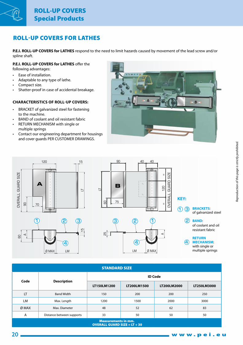
ROLL-UP COVERS FOR LATHES
P.E.I. ROLL-UP COVERS for LATHES respond to the need to limit hazards caused by movement of the lead screw and/or
spline shaft.
P.E.I. ROLL-UP COVERS for LATHES offer the
following advantages:
• Easeofinstallation.
• Adaptabletoanytypeoflathe.
• Compactsize.
• Shatter-proofincaseofaccidentalbreakage.
CHARACTERISTICS OF ROLL-UP COVERS:
• BRACKETofgalvanizedsteelforfastening
to the machine.
• BANDofcoolantandoilresistantfabric
• RETURNMECHANISMwithsingleor
multiple springs
• Contactourengineeringdepartmentforhousings
and cover guards PER CUSTOMER DRAWINGS.
STANDARD SIZE
Code Description
ID Code
LT150LM1200 LT200LM1500 LT200LM2000 LT250LM3000
LT Band Width 150 200 200 250
LM Max. Length 1200 1500 2000 3000
Ø MAX Max. Diameter 48 52 62 83
A Distance between supports 33 50 50 50
Measurements in mm. OVERALL GUARD SIZE = LT + 30
BRACKETS: of galvanized steel
BAND:
of coolant and oil
resistant fabric
RETURN MECHANISM: with single or multiple springs
KEY:

21
ROLL-UP COVERS
Special Products
w w w . p e i . e u
Rep
rod
uct
ion
of
this
pa
ge
is s
tric
tly
pro
hib
ited
.
WELD SCREEN
WELD SCREEN is a protection screen for welding and grinding stations.
• WELD SCREEN offers protection to personnel who are in the vicinity of welding and grinding work areas. The semi-
transparent screen protects personnel from contact with metal chips and sparks produced during the welding and
grinding processes.
• WELD SCREEN is fitted with a mobile stand allowing the user to adjust the screen as required.
• WELD SCREEN is foldaway making it compact and portable.
2085
650
110
90
20
00
1900
TECHNICAL DATA
✔ WEIGHT: 8,9 Kg
✔ REFERENCE STANDARD: UNI EN 1598
DL 626/94 DL 81/2008
✔ AVAILABILITY: Immediate
SIZES
Roll-up covers REVISION
BEFORE
AFTER
• OverhaulofALLTYPESofROLL-UPCOVERSANDSHUTTERINGSWITHORwithoutCanister
• ReplacementofthedamagedFLEXIBLECOVER,SHUTTERINGorBAND
• ReplacementoftheMECHANISM
• ReplacementofWIPERSorotherCOMPONENTSifworn-out
• CleaningandbuffingofALLSURFACEStooriginalfinish
• Iftheroll-upcovershouldbetoodamaged,wecanbuildanewone
SHORTDELIVERYTIME

22
ROLL-UP COVERS
Special Products
w w w . p e i . e u
Rep
rod
uct
ion
of
this
pa
ge
is s
tric
tly
pro
hib
ited
.UP TO 120 mt/min
Roll-up Covers with COVER TYPE J
Roller protections equipped with type-J SHUTTERING are particularly suitable for covering large bases, pits or holes. These
protections have the following characteristics:
• SPEED: suitableforhighspeedapplications,bothdryandcoolantprocessing.
• QUIET: thankstothemechanicalrollersystem,thereisnonoisecausedbycollisionsorvibrations.
• STRENGTH: particularlysuitableforwalk-onapplications.
• CLEANING: thebeltslideonthesideoftheshavingconveyorhasbeendesignedtomaketheshavingfall intheconveyor
withoutcausinganyclogging.
• RAPID MAINTENANCE: ifsomeelementsaredamagedthebeltdoesnotneedtoberemoved.Thedamagedelementscanbe
removedsimplybyunscrewinglateralscrews.
SPEED
STRENGTH
CLEANING
RAPID
MAINTENANCE
The wiper is slightly angled relative to the travel direction of the cover so as to force the chips and coolant towards the chip conveyor trough side.

23
ROLL-UP COVERS
Special Products
w w w . p e i . e u
Rep
rod
uct
ion
of
this
pa
ge
is s
tric
tly
pro
hib
ited
.
Special Product: Roll-up Covers with Chain Movement
• Thebandis fixedrelativetothefloor,allowingpeopletocross
the machine trench at any time even while the machine is in
operation.
• Duringoperation,thespecial interconnectingchaincausesthe
unwinding action of one roll to automatically wind-up the
opposite roll. Our patented compensating mechanism keeps the
system in balance, even though the diameters of rolls continously
change.
• Thepatentedcompensatingmechanismisverycompactandis
mounted to the machine column in its own canister.
• Thepatenteddesign insuresaperfectly functionalandreliable
design.
• Uponrequest,wecandesignasystemusingDCorpneumatic
motors.
• Thedimensions, layout, and speedof travel aredeveloped for
each order and can meet your exact needs.
P.E.I. manufactures these moving walkway/pit covers for horizontal, mobile surfaces, to meet accident prevention and safety
regulations. These units cover the upper part of the machine pit whose base is below the walking surface and allow the crossing
of the pit by anyone, thus avoiding possible accidents or damage to people or equipment which could occur with the pit
uncovered.
The variable speed drive system, which allows for mechanical speed control, makes the drive system independent from the
general machine control system. Size and speed are established by the customer and studied by our technical staff in order to
obtain optimal operation.
TECHNICALDATAFORCOVERTYPEJ
• Entirely made of metal
• Perfectflatness of the side exposed to chips
• Cleaningwiper on the side exposed to chips
• Shielded joint with integrated labyrinth to
prevent coolant from getting trough
• Highbending resistance. See graphic of
Span/Capacity
• Reinforced version with steel profiles
• Highly resistant to tensile stress.
Minimum guaranteed 2 KN/m of width
• Steellateralcapswithchain joint
• Thicknessofthecarpet:18 mm
• Take-upinbothdirectionsona150 mm diameter
• Reducedweight:12.5 kg/sqm
(29 kg/sqm for the reinforced version)
• Modular system with individual
interchangeable elements
• Operatingspeedsupto120 m/min
• Lifeguaranteed:1.000.000 movements
P.E.I.’s patented system of ROLL-UP COVERS WITH CHAIN MOVEMENT have the essential feature of keeping the strip perfectly fixed
while the machine is running.
Roll-up Covers with COVER TYPE J
6.000
5.500
5.000
4.500
4.000
3.500
3.000
2.500
2.000
1.500
1.000
500
0
0 10 20 30 40 50 60 70 80 90 100 110 120 130 140 150
Su
pp
ort
sp
an
Deflection to the centre
1% of the span
Capacity (kg/m2)
STANDARDAlluminium
STIFFENEDalluminium steel

Rep
rod
uct
ion
of
this
pa
ge
is s
tric
tly
pro
hib
ited
.
24
FLEXIBLE ALUMINUM COVERS
w w w . p e i . e u
Rep
rod
uct
ion
of
this
pa
ge
is s
tric
tly
pro
hib
ited
.
Standard end
mount profiles:
H
B
1T
L2
L1
S2T
H
B
3T
L2
S
L1
5T (1/2/3/4)
L1
S
L2
6T
COD
E
Minimum windingdiameter
Cove
r w
eigh
t
Cove
r cl
ean
ing
Bending strength, support distance*
Max
. ch
arge
pe
rmit
ted
Impa
ct t
este
dEN
1241
7
An
ti-s
liptr
eatm
ent
With upper
roller
With lower
roller (90 Kg) (150 Kg)kg each wheel
Ø100mm mm Kg/m2 mm mm Kg
JH 200 200 25,0 Wiper 4500 4000 75 250 Upon request
JL 100 100 12,2 Wiper 1200 1000 50 90 Upon request
J 150 150 12,5 Wiper 2200 1750 50 150 Upon request
JB / 60 9,5 Wiper 750 600 50 150 Not available
AKS1 50 50 9,0 Brush 750 600 / - Not available
AKS4 / 50 9,0 Wiper 750 600 10 - Not available
MATERIAL: Anodized grey aluminum * Max. bending 1% of the support distance MAX. FEASIBLE WIDTH: 6000 mm
DC
E7T
We can provide end mountings to match customer drawings upon request.
Terminal
CODEL1xL2xS BxH C D E
Mat
eria
l
Des
crip
tion
Cover
CODE
1T 25x5,5 Al Flat AKS-1/AKS-4
2T 20x30x5,5 Al Corner AKS-1/AKS-4
3T 20x6 Al Cover JB
5 T/1 15x15x3 Al-Stl Corner JB
5 T/2 20x20x3 Al-Stl Corner JB
5 T/3 30x30x3 Al-Stl Corner J / JB / JL
5 T/4 40x40x5 Stl Corner J / JH
6T 30x30x2 Stl HingedAKS-1/AKS-4J/JL/JH/JB
7TDrilling upon request only
182035
ø 5,50ø 8,50ø 13
ø 10ø 14ø 20
Al CoverJLJJH
Al = Aluminum Stl = Steel
25,40
10
20,80
6
5
Brass cap
35
57,15
18
38,10
JB (patented)
JH (patented)
JL (patented)
J (patented)
5,5
20,52AKS - 4
AKS - 120,52
5,5
Polyurethane joint
Im
pact tested EN 12417
All the FLEXIBLEROLL-UPCOVERSof"J"RANGEare IMPACTTESTEDaccording to EN12417.
Joule

25
RIVETED APRON COVERS
w w w . p e i . e u
Rep
rod
uct
ion
of
this
pa
ge
is s
tric
tly
pro
hib
ited
.
Visible side
CODE
Possible combinations
of materials
Minimum winding
diameter (mm)Max. feasible
width
(mm)Upper Lower With With
elements elements upper roller lower roller
1001/1 Al-Stl-Br 50 30 2000
1001/2 Al-Stl-Br 70 30 2000
1001/3 Al 70 30 2000
1002 Al Al-Stl-Br 40 40 2000
1003 Al-Stl-Br Al-Stl-Br 70 40 2000
1006 Al Al-Stl-Br 70 50 2000
Al= Aluminum Stl= Steel Br= Brass
L1
S
L2
L1
S
L2
Standard end mount profiles:
1001/2 Visible side
18
192
0,63,3
1002 Visible side
20
15
2,8
2
1
5,8
21
5 T (1/2/3)
1003 Visible side
20
15
2
2
1
5
21
1006 Visible side
16
1615
3 16
2
1001/3 Visible side
16
16
3
0,64,3
Code L1xL2xS Material
5T/1 15x15x3 Al - Ac
5T/2 20x20x3 Al - Ac
5T/3 30x30x3 Al - Ac
6T 30x30x2 Stl hinge
1001/1 Visible side
15
16
2
0,63,3
6 T
We can provide end mounts to match customer drawings upon request.

26
FLAT COVERS
w w w . p e i . e u
Rep
rod
uct
ion
of
this
pa
ge
is s
tric
tly
pro
hib
ited
.
X-Y LM SHIELD with Thermic-Welded Covers and Movable Plates
• TheX-YLMSHIELD composed of thermic-welded bellows with steel laminations, represents the cheapest solution for protecting the
working area in horizontal spindle machining centers where there is a large production of hot shavings.
This system consists of No. 2 horizontal bellows and No. 2 vertical bellows, protected by movable stainless steel plates guaranteeing a very
functional product for Quality/Price.
• Accelerationsupto1G
• Speedsup120m/min.
• Thethermic-weldedprotectionbellowsarelargelyusedoneverykindofmachinetool.Theyarefrequentlyusedinmachiningcenters
and chip-removing machines. In order to protect the bellow exposed to hot shavings, a shielding made by metal elements, called “plates”
will be necessary. The steel laminations are fixed by special clamps keeping the plates adherent and loaded one on the other to prevent
contaminants and shavings from entering.

27
FLAT COVERS
w w w . p e i . e u
Rep
rod
uct
ion
of
this
pa
ge
is s
tric
tly
pro
hib
ited
.
P.A. = Open length B = Outside width
P.C. = Closed length a = Outside height
Stroke = Open length - closed length x = Fold height
Example:
Given that: Fold height = 15 mm
Open length = 1000 mm
Opening of 1 fold = 15 x 2 - 8 = 22
Number of folds = = 48
Closed length = (0,25* x 8 + 1**) x 48 + (2 *** x 2)
Closed length = 3 x 48 + 4 = 148
Closed length = 148 mm
* We hypothesize the fabric material with code
“TEMAT015” (see materials list on page 32)
** We hypothesize that the stiffener is 1 mm thick
*** We hypothesize that the flange is 2 mm thick (see
materials list on page 31)
AP = Opening of 1 fold = x . 2 - 8
SM = Fabric thickness *
SS = Stiffener thickness *
SF = Flange thickness *
NP = Number of folds =
P. C.= (SM . 8 + SS) . NP + (SF . 2)
THERMIC-WELDED COVERS
Fabric materialFlange 2
Stiffener
Flange 1
Formula for calculating the CLOSED LENGTH
P.A. + 2
AP
* See materials list on page 31.
This data sheet shows only one type of Thermic-Welded Cover
that we manufacture.
Contact our engineering department for other types.
1000 + 2
22
BAP
2
a
x
P.A.
Stroke P.C.

28
FLAT COVERS
w w w . p e i . e u
Rep
rod
uct
ion
of
this
pa
ge
is s
tric
tly
pro
hib
ited
.
THERMIC-WELDED COVER WITH FLEXIBLE LAMINATIONS
Stiffener
Flange 1
Vertical working position only
Opening of 1 fold = (x.2) - 16
SM = Fabric thickness *
SS = Stiffener thickness *
SF = Flange thickness *
NP = Number of folds =
P. C. = (SM . 8 + SS) . NP + (SF . 2)
Formula for calculating the CLOSED LENGTH
P.A. + 2
AP
* See materials list on page 31
This data sheet shows only one type of Thermic-Welded Cover
that we manufacture.
Contact our engineering department for other types.
x(mm) 15 20 25 30 35 40 45
Z(mm) 40 50 60 70 80 90 100
P.A. = Open length B = Outside width
P.C. = Closed length a = Outside height
Stroke = Open length - closed length x = Fold height
Example
Given that: Fold height = 30 mm
Open length = 1000 mm
Opening of 1 fold = (30 x 2) - 16 = 44
Number of folds = = 25
Closed length = (0,25* x 8 + 1**) x 25 + (2*** x 2)
Closed length = 3 x 25 + 4 = 79
Closed length = 79 mm
* We hypothesize the fabric material with code
“TEMAT015” (see materials list on page 32)
** We hypothesize that the stiffener is 1 mm thick
*** We hypothesize that the flange is 2 mm thick
(see materials list on page 31)
1000 + 2
44
Fabric
material
Flange 2
B
a
x
Z
P.A
.
Str
oke
P.C
.
AP
6

29
FLAT COVERS
w w w . p e i . e u
Rep
rod
uct
ion
of
this
pa
ge
is s
tric
tly
pro
hib
ited
.
THERMIC-WELDED COVER WITH FIXED LAMINATIONS
Example
Given that: Fold height = 45 mm
Open length = 1800 mm
Opening of 1 fold = 45 x 2 - 16 = 74
Number of folds = 1800 + 2 = 27
74
Closed length = (0,35* x 8 + 1**) x 27 + (3*** x 2)
Closed length = 3,8 x 27 + 6 = 109
Closed length = 109 mm
* We hypothesize the fabric material with code
“TEMAT151” (see materials list on page 32)
** We hypothesize that the stiffener is 1 mm thick
*** We hypothesize that the flange is 3 mm thick
(see materials list on page 31)
Fabric material
Flange 2
Stiffener
Flange 1
Working position:
Horizontal
Vertical
Frontal
AP = Opening of 1 fold = x . 2 - 16
SM = Fabric thickness *
SS = Stiffener thickness *
SF = Flange thickness *
NP = Number of folds=
P. C. = (SM . 8 + SS) . NP + (SF . 2)
Formula for calculating the CLOSED LENGTH
P.A. + 2
AP
* See materials list on page 31
This data sheet shows only one type of Thermic-Welded Cover
that we manufacture.
Contact our engineering department for other types.
x(mm) 15 20 25 30 35 40 45
L(mm) 16 21 26 33 43 48 56
P.A. = Open length B = Outside width
P.C. = Closed length a = Outside height
Stroke = Open length - closed length x = Fold height Z(mm) 45 55 65 75 85 95 105
Possible special
fixing to facilitate the
mounting of the first
steel lamination
B
a
x
Z
P.A
.
Str
oke
P.C
.
L
AP
6
30
FLAT COVERS
w w w . p e i . e u
Rep
rod
uct
ion
of
this
pa
ge
is s
tric
tly
pro
hib
ited
.
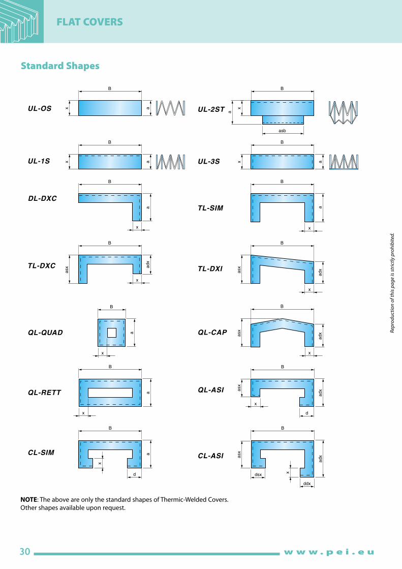
Standard Shapes
NOTE: The above are only the standard shapes of Thermic-Welded Covers.
Other shapes available upon request.

31
FLAT COVERS
w w w . p e i . e u
Rep
rod
uct
ion
of
this
pa
ge
is s
tric
tly
pro
hib
ited
.
Thermic-Welded Cover materials
Description Thickness Heat resistance
(mm)
TEMAT 091 PVC Fiberglass PVC 0,44 +300 -30 + 80
TEMAT 106 Ptfe Polyester Polyurethane 0,30 +200 -30 +120
TEMAT 015 Polyurethane Polyester Polyurethane 0,25 +200 -30 + 90
TEMAT 151 Polyurethane Polyester Polyurethane 0,35 +200 -30 + 90
TEMAT 164 Polyurethane Kevlar* Polyurethane 0,35 +350 -30 +180
TEMAT 165 Polyurethane Nomex* Polyurethane 0,36 +300 -30 +130
TEMAT 169 Polyurethane Panox*/Kevlar Polyurethane 0,33 +300 -30 +130
TEMAT 017 PVC Polyester PVC 0,36 +100 -30 + 70
TEMAT 020 PVC Polyester PVC 0,25 +100 -30 + 70
Fabric suitable for minor welding splatter. Also appropriate around acids. Self-extinguishing.
Excellent resistance to oils and chemical products. No adhesive surface. Low friction coefficient. Excellent chemical inertia.Excellent resistance to abrasion and bending strength. Mainly used in grinding machines.
Excellent resistance to petroleum products, oils and heavy abrasion. Excellent bending strength.
Excellent resistance to petroleum products, oils and heavy abrasion. Excellent bending strength. Excellent mechanical strength. Kevlar also has excellent shear strength. Normally used when there is heavy mechanical stress, a large amount of sharp shavings, and at high temperatures.
Excellent resistance to petroleum products, oils and heavy abrasion. Excellent bending strength. Excellent mechanical strength. Good resistance to minor welding splatter or hot material. Widely used in laser cutting machines. Self-extinguishing.
Excellent resistance to petroleum products, oils and heavy abrasion . Excellent bending strength. Excellent mechanical strength. Good resistance to minor welding splatter or hot material. It may be considered as the best fabric on the market for use in laser cutting machines. Self-extinguishing.
Mainly used around heavy ambient dust, minor splatters of coolant and oil. Also suitable for use around acids.
Visible
side
Fabric
insertInternal
side
Primary
resistance
characteristics
Momentary
contact
°C
Continuous
min. °C max. °C
Stiffener materials
Stiffener material code Description Thickness (mm) Notes
Flange materials
AL Aluminum 2,0 - 3,0
AC Steel 2,0 - 3,0 - 4,0
PVC PVC 2,0 - 3,0
Flange material code Description Thickness (mm)
Lamination materials
Lamination material code Description Primary applications
* Kevlar and Nomex are registered Dupont trademarks ** NOT recommended for Thermic-Welded Covers with laminations.
Contact our engineering department for other materials and applications.
PVC 05 PVC 0,50 ** Outside width (B) up to 300 mm
PVC 10 PVC 1,00 Outside width (B) from 301 up to 700 mm
PVC 15 PVC 1,50 Outside width (B) from 701 up to 1500 mm
Fabric
material
code
Aluminum
(Baked Enamel Finish)AL
INOX
For use around welding splatter, small and medium-sized hot shavings. Especially suitable for use around continuous sparks. Appropriate where lightweight materials are necessary.
In work environments with large shavings. Especially suitable for use around acids.

32
FLAT COVERS
w w w . p e i . e u
Rep
rod
uct
ion
of
this
pa
ge
is s
tric
tly
pro
hib
ited
.
Flange Fastening Systems
• Solutionwithsheetsteel,aluminumorPVCflange
• Shapeandholespercustomerdrawings
• Solutionwithsheetsteel,aluminumorPVCflange
• Shapeandholespercustomerdrawings
• Solution with connector flange protruding from
the cover profile, made of sheet steel, aluminum or
PVC
PVC stiffener PVC
Stiffener
Flange
FlangeType A
Type B1
• Solutionwithsheetsteelflange
• Shapeandholespercustomerdrawings
• Threadedflangeholes
Type C
Type F
Type I
Type B2
Type G
PVC cover stiffener
Strip of Velcro applied to the machine
FlangeStrip of Velcro applied to the machinePVC
stiffener
Type E Type H
Flange
Counterflange
Entire fold in PVCSolution with STRONG HOLD rapid connection.
A PVC support and flange act as a flange, to which the
STRONG HOLD rapid connection is applied. The flange
is made of sheet steel, aluminum or PVC, shape and
holes per customer drawings. This solution offers:
• Rapidapplicationandremovalofthecover
• Foamgasketstripprovidesatightsealaroundthe
connection
Recommended for wet work environments
Solution with rapid VELCRO connection.
A PVC support acts as a flange, with
VELCRO strips applied to the stiffener
and directly to the machine.
This solution offers:
• Rapidapplicationandremovalofthecover
• Lowcost
Recommended for dry work environments
34
FLAT COVERS
w w w . p e i . e u
Rep
rod
uct
ion
of
this
pa
ge
is s
tric
tly
pro
hib
ited
.
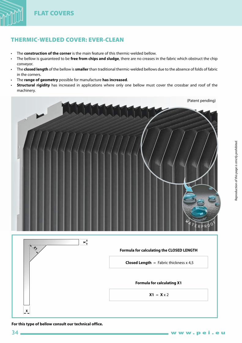
Closed Length = Fabric thickness x 4,5
X1 = X x 2
Formula for calculating the CLOSED LENGTH
Formula for calculating X1
WATERPRO
OF
THERMIC-WELDED COVER: EVER-CLEAN
• Theconstruction of the corner is the main feature of this thermic-welded bellow.
• The bellow is guaranteed to be free from chips and sludge, there are no creases in the fabric which obstruct the chip
conveyor.
• Theclosed length of the bellow is smaller than traditional thermic-welded bellows due to the absence of folds of fabric
in the corners.
• The range of geometry possible for manufacture has increased.
• Structural rigidity has increased in applications where only one bellow must cover the crossbar and roof of the
machinery.
(Patent pending)
X
X
X1
For this type of bellow consult our technical office.

35
FLAT COVERS
w w w . p e i . e u
Rep
rod
uct
ion
of
this
pa
ge
is s
tric
tly
pro
hib
ited
.
THERMIC-WELDED COVER WITH LAMINATIONS: MULTI-STEEL
• Thermic-weldedbellowswithlaminationsonmanysidesaretheidealsolutionforcomplete protection of the roof and
crossbar in multi-shaft working centres.
• Thecornersareclosedandsteelinoxlaminationsappliedwithaperfect 90° fold in merit of the elastic deformation of
the material and a special geometry.
• More than two sides can be covered and with different angles.
For this type of bellow consult our technical office.
(Patent pending)

36
FLAT COVERS
w w w . p e i . e u
Rep
rod
uct
ion
of
this
pa
ge
is s
tric
tly
pro
hib
ited
.
Thermic-Welded Covers for Linear Slides
Open Length
Closed
Length
H
Xh
Stroke
W
W 1X
NOTE: For the W1 slide over size 65, please contact our Technical Dept.
Example of bellows mounted on linear slides
List of Standard Material
Standard Thermic-Welded Covers Size Example of the identification code of a Thermic-Welded Cover for Linear Slides complete with flange
Type of material Stiffener Fabric materialClosed length
for 1000 mm of open length
S1PVC
0,50
PVC + Polyester + PVC
0,25 (TEMAT020)90
P1PVC
0,50
Polyurethane + Polyester + Polyurethane
0,25 (TEMAT015)90
LXPVC
1,00
Polyurethane Panox/Kevlar + Polyurethane
0,33 (TEMAT169)150
Slide nominal
value
W1
Ply
height
X
Bellow
width
W
Total
height
H
Slide
deviation
h
15 19 56 36 5
20 19 61 40,5 5
25 19 67 43 7,5
30 19 72 51 8
35 19 76,5 51 9
45 19 87,5 61 10
55 25 108 73 15
65 32 132 90 15
Slide manufacturer THK
Slide model HSR
Slide nominal value (W1) 35
Open length(stroke + closed length)
1500
Type of material P1
Flange fixing system A-A(see page 37)
Questionnaire for Thermic-Welded Covers for Linear Slides
Company name ..............................................................
Phone: .............................................................................
E-mail:. ............................................................................
Quantity: .........................................................................
Annual demand: ............................................................
.........................................................................................
Date: ................................................................................
Notes:. .............................................................................
.........................................................................................
.........................................................................................
Slide Manufacturer ........................................................................................................
Slide Model ........................................................................................................................
Slide Nominal Value (W1) ❏ 15 ❏ 20 ❏ 25 ❏ 30
❏ 35 ❏ 45 ❏ 55 ❏ 65
Open length (Stroke + Closed length) .........................................................mm
Fabric type ❏ S1 ❏ P1 ❏ LX
Fastening system ❏ Solution A with clamps
on guide top ❏ Solution B1 with flange in PVC
Fastening system ❏ Solution A with clamps
to table ❏ Solution B2 with flange in PVC
NOTE: The data fields and/or tables marked by are the least ones to be filled in order to give you a quotation. Please send an e-mail to
[email protected] or a fax to +39 051 6464840.

37
FLAT COVERS
w w w . p e i . e u
Rep
rod
uct
ion
of
this
pa
ge
is s
tric
tly
pro
hib
ited
.
Thermic-Welded Covers Standard Systems for Linear Slides
M
M
W 4
2.3
11 6
22
Ø 4
.5
C
2
Ø 4.5
Ø 4.5
C1
W
=
W
= = =3
= =
1 3
21 3 4
4
H
4C H
1
6
3
The "M" zone must be screened with a plate fixed on the table side.
The "M" zone must be screened with a plate fixed on the table side.
Solution A: Fastening holdfast
Solution B: Velcro flange fastening (B1 and B2)
Suitable for bellows fastening in positions 1 - 2 - 3 - 4,
with angular or plate supports provided by customers
Standard flange
Type B2 in PVC
Bellows-fastening standard systems
for linear slides
Suitable for dry working places
This technical card represents the standard systems used for the fastening of bellows for linear slides we can provide. For different sizes, please contact our
technical department.
Standard flange
Type B1 in PVC
Pos.1 a) Fix the type 1 standard flange at the head of the slide.
b) Fix the bellows to the type 1 standard flange by pressing strongly.
Pos.2-3 a) Fix the table or the mounting plate to the type 2 standard flange by means of screws.
b) Fix the bellows to the type 2 standard flange by pressing strongly.
Pos.4 a) Fix the type 2 standard flange to the angular support provided by the customer by means of screws.
b) Fix the bellows to the type 2 standard flange by pressing strongly.
N.B. Fastening options showed in Pos. 1-4 are interchangeable
SLIDE W C N. HOLES
15 52 26 2
20 57 29 2
25 63 32 2
30 68 34 2
35 72 36 2
45 83 28 3
55 104 35 3
65 128 32 4
SLIDE W H C H1 C1 N.
HOLES
15 56 36 0 42 26 2
20 61 40,5 8 46,5 29 2
25 67 43 8 46,5 32 2
30 72 51 8 54 34 2
35 76,5 51 18 53 36 2
45 87,5 61 18 62 28 3
55 108 73 18 69 35 365 132 90 18 86 32 4

38
FLAT COVERS
w w w . p e i . e u
Rep
rod
uct
ion
of
this
pa
ge
is s
tric
tly
pro
hib
ited
.
a
AP
B
XPCP
Formula for calculating the CLOSED LENGTH
NP = Number of folds =
P.C. = NP • PCP + 10 mm
P.A.
AP
Patented
BELLOWS FOR HOISTING PLATFORM
Bellows DuratiteTM
• Preventionofimpedimentofthehoistpantograph
• Protectionfromdust,dirtorforeignparticles
X AP PCP Material Color Reference code
38 55 10PVC/PU Yellow/Black DM-PU-G
PVC/PU Black DM-PU-N
67 100 10PVC Yellow/Black DM-PU-G
PVC Black DM-PU-N
89 125 10 PVC Yellow/Black DM-PU-G

39
FLAT COVERS
w w w . p e i . e u
Rep
rod
uct
ion
of
this
pa
ge
is s
tric
tly
pro
hib
ited
.
Thermic-welded Bellows
Type QL-RETT
Systems for fastening Bellows for Lift Tables
T5
T1T2
T4
P.A
.
P.C
.
T3
T6
BELLOWS FOR HOISTING PLATFORM
• All calculation formulas are shown on page 27.
EXAMPLES OF APPLICATION:
• Closingofuprightdoors • Protectionoflevelchanginginassemblylinesofthemanufacturingindustry
• Closingofstorehouseroomsandinterspaces • Baseprotectionofmedicalequipment
a
X
B
I CI CEB E
Solution with sheet steel,
aluminum or PVC flange.
Shape and holes per
customer drawings.
Bellows inner collar.
Suitable for screw
fastening.
Bellows outer collar.
Suitable for screw
fastening.
Solution with sheet steel,
aluminum or PVC flange.
Shape and holes per
customer drawings.
Solution with rapid VELCRO
connection.
This solution offers:
• Rapidapplicationand
removal of the cover
• Lowcost
Questionnaire for hoisting platforms BELLOWS:
a = .............................................................................................................. mm
B = .............................................................................................................. mm
X = .............................................................................................................. mm
Questionnaire for HOISTING PLATFORMS:
T1 = .......................................................................................................... mm
T2 = .......................................................................................................... mm
T3 = .......................................................................................................... mm
T4 = .......................................................................................................... mm
T5 = .......................................................................................................... mm
T6 = .......................................................................................................... mm
P.A. = ...................................................................................................... mm
P.C. = ...................................................................................................... mm
NP = .......................................................................................................... mm
Upper side fastening ❏ I ❏ B ❏ E ❏ C I ❏ CE
Lower side fastening ❏ I ❏ B ❏ E ❏ C I ❏ CE
NOTE: The data fields and/or tables marked by are the least ones to be filled in order to give you a quotation. Please send an e-mail to
[email protected] or a fax to +39 051 6464840.

40
FLAT COVERS
w w w . p e i . e u
Rep
rod
uct
ion
of
this
pa
ge
is s
tric
tly
pro
hib
ited
.
P.A. Open length
P.C. Closed length
Stroke (P.A. - P.C.)
a Outside height
B Outside width
x Fold height
d Return dimension
AP Fold opening
NP Number of folds
FLAT COVERS GLUED AND SEWN
APAP
x
Type CL-SIM
Type TL-SIM
Formula for calculating the CLOSED LENGTH
Glued style “A”
P.A. +2 AP
APAP
4
4
x
Formula for calculating the CLOSED LENGTH
Sewn style “C”
P.A. +2 AP
NP= Number of folds =
Ref. Description Dim. Type Style
P. C.= NP . 4 + flange thickness
AP= Opening of 1 fold = x . 1,41
AP= Opening of 1 fold = (x-8) . 1,41
Contact our engineering department for this type of cover.
AP
B
x
a
AP
d
B
x
a
P. C.= NP . 2,5 + flange thickness
NOTE: The data fields and/or tables marked by are the least ones to be filled in order to give you a quotation. Please send an e-mail to
[email protected] or a fax to +39 051 6464840.
NP= Number of folds =
P.A. P.C.
Mobile carriage

41
FLAT COVERS
w w w . p e i . e u
Rep
rod
uct
ion
of
this
pa
ge
is s
tric
tly
pro
hib
ited
.
BELLOWS FOR LASER AND PLASMA MACHINES

42
FLAT COVERS
w w w . p e i . e u
Rep
rod
uct
ion
of
this
pa
ge
is s
tric
tly
pro
hib
ited
.
BELLOWS FOR OVERHEAD PROTECTION FOR PORTAL MILLING MACHINES:
WAVE SkY
• WAVESKY is a bellow that limits the escape of fumes, dust and chips from the workstation area.
WAVESKY bellow reduces the suction force created during working: carbon fibres, composite materials and vaporised
cooling lubricant.
The special translucent fabric guarantees ample light in the work area.
The motorised version makes for a quick opening and closing of the overhead apparatus.
✔ MAX SPEED: 90 mt/min.
✔ MAX ACCELERATION: 1g
✔ MAX WIDTH BETWEEN GUIDES: 8.000 mm
✔ MAXIMUM STROKE: 25.000 mm
✔ STANDARD FOLD HEIGHT: 200 / 250 / 300 mm
TECHNICAL SPECIFICATIONS EXAMPLE OF APPLICATION

43
FLAT COVERS
w w w . p e i . e u
Rep
rod
uct
ion
of
this
pa
ge
is s
tric
tly
pro
hib
ited
.
BELLOWS FOR OVERHEAD PROTECTION FOR PORTAL MILLING MACHINES:
WAVE SkY
Structural aluminium frames
Lateral guides
modular and adjustable
Soundproof fabric
for damping at full stroke
Guide cover casing
Sliding along the
aluminium guides is
ensured by rollers
Automatic motorisation
opening/closing available on request
Bellow cover in
translucent and
double weave fabric
TEMAT 154
CERAMIX has an excellent abrasion resistance and excellent shear strength. CERAMIX shows excellent resistance to mineral oils and hot temperatures. The two-ply fabric insert gives an high transverse rigidity and a very attractive appearance. In WAVE-SKY only CERAMIX is used in the bellow folds close to the working area, when large quantities of ALUMINUM hot and shearing shavings are produced, in cases of high speed chip-removing dry work environments. ANTISTATIC-PROOF and SELF-EXTINGUISHING.
Excellent resistance to petrol based products, oils and strong abrasion. The textile insert is made of a special fabric with high rigidity in the diagonal weave plus an aesthetically pleasing appearance. It is normally used in environments where there are large quantities of chips.TRANSLUCENT and ANTI-STATIC.
** Ceramic Polymer Technology
TEMAT154 Polyurethane Polyester Polyurethane 0,9 +130 -30 +90
TEMAT180 CPT** Polyester - 1,6 +1200 -25 +300
Code Primary resistance characteristicsVisible
side
Fabric
insert
Hidden
side Thic
knes
s
Momentary
contact °C
Continuous
°C
Description of materials Heat resistance

44
ROUND BELLOWS
w w w . p e i . e u
Rep
rod
uct
ion
of
this
pa
ge
is s
tric
tly
pro
hib
ited
.
• Economicbellows
• Goodresistancetochemicals
• Resistancetoheatcompatiblewiththeusedmaterials(seecharacteristicsonpages52-53)
• Theycanbesuppliedinavarietyofgeometricalshapes,withlowcostproductionofmoulds(ifnotalreadypresentinourstock).
• Materialsavailable:
Code TEMAT 018
Code TEMAT 019
Code TEMAT 153
See the characteristics shown in the tables on pages 52-53.
THERMIC-WELDED TIGHT BELLOWS
Theyareusedwhenwatertightprotectionofthecomponents(i.e.screws,shafts,etc.)isnecessaryagainstthe
contaminationmadebycoolants.

45
ROUND BELLOWS
w w w . p e i . e u
Rep
rod
uct
ion
of
this
pa
ge
is s
tric
tly
pro
hib
ited
.
P.C.= Closed Length = NP . SP*
Materials available:
• PolyestercoatedwithNeoprene*andHypalon*
• PolyestercoatedwithNitrilrubber
• PolyestercoatedwithPolyurethane
• PolyestercoatedwithPVC
• Kevlar*coatedwithNeoprene*andHypalon*
• Kevlar*coatedwithPolyurethane
• FiberglasscoatedwithSiliconeandNeoprene*
• FiberglasscoatedwithPVC
• Aluminum-coatedfabrics
* Neoprene, Hypalon and Kevlar are registered
Dupont trademarks
(see materials list on pages 52-53)
SEWN ROUND BELLOWS
Theseareusedwhenstrongrotationresistanceisrequired(forinstance,tocoverballscrews)andwhereaverycompact
closedpackisrequired.
• Highlyreliablebellows • Notoolingcosts
• Highresistancetomechanicalanddynamicstress • Withselectededging (in safety colors upon request)
• Resistancetocoolants and oils • Minimuminternaldiameterstarting at 20 mm
• Suitableforhigh temperatures • Any size external diameter
• Availablewithguidebushings and reinforcement rings • Goodprice/quality ratio
Formula for calculating the CLOSED LENGTH
P.A. +1 AP
NP= Number of folds =
AP= Opening of 1 fold = (Ø e. soff.- Ø i. soff. -6) . 1,2
2
* SP= Thickness of 1 fold; see materials list on page 52-53
Note: When steel rings are required inside the folds, the P.C. is calculated by our engineering department.
Int. c. Ø
Int. f. Ø
Int. Ø (ID)
Int. hole Ø
Ext. f. Ø
Holes no. Ø
P.A
.= O
pen L
ength
H1
x
Ext. Ø (OD)
Str
oke
P.C
.
Guide bushing
Reinforcement rings

46
ROUND BELLOWS
w w w . p e i . e u
Rep
rod
uct
ion
of
this
pa
ge
is s
tric
tly
pro
hib
ited
.
Theseareusedwhenhighmechanicalstrengthand
heatresistancearerequired.
HEAT-FORMED BELLOWS
Materials available:
• PolyestercoatedwithNeoprene*andHypalon*
• PolyestercoatedwithNitrilrubber
• PolyestercoatedwithPolyurethane
• PolyestercoatedwithPVC
• FiberglasscoatedwithSiliconeand
Neoprene*
* Neoprene and Hypalon are registered
Dupont trademarks
(see materials list on pages 52-53)
Upon request with
longitudinal opening seam
when the bellow must be disassembled
without dismantling the part to be protected
Formula for calculating the CLOSED LENGTH
P.C.= Closed Length = NP . SP*
P.A. +1 AP
NP= Number of folds =
AP= Opening of 1 fold = (Ø e. soff.- Ø i. soff. ) . 1,41
2
* SP= Thickness of 1 fold; see materials list on pages 52-53
OPEN HEAT-FORMED BELLOWS
H1
Int. c. Ø
Int. f. Ø
Int. Ø (ID)
Int. hole Ø
Ext. f. Ø
Holes no. Ø
P.A
.= O
pen L
ength
H1
x
Ext. Ø (OD)
Str
oke
P.C
.
AP
Note: When steel rings are required inside the folds, the P.C. is calculated by our engineering department.
• Excellentresistancetomechanical stress
• Alsoavailablecone-shaped
• Resistancetocoolants and oils
• Notoolingcosts
• Availablewithguidebushings and reinforcement rings
upon request
• Suitableforhigh temperatures

47
ROUND BELLOWS
w w w . p e i . e u
Rep
rod
uct
ion
of
this
pa
ge
is s
tric
tly
pro
hib
ited
.
Bellows type
Questionnaire for Round Bellows
❏ A
Fastening system
❏ Sewn
❏ Heat-formed
❏ Thermic-welded
❏ B
❏ C
Int. c. Ø
Int. f. Ø
Int. Ø (ID)
Int. hole Ø
Ext. f. Ø
Hole no. Ø
P.A
.= O
pe
n le
ng
thH
1
Ext. Ø (OD)
Str
oke
P.C
. Guide bushing
Temperature of material falling on the bellows:
................................................................................ °C
Working position:
❏ Horizontal ❏ Vertical
• Parttobeprotected:
❏ Stem or shaft:
Diameter .....................................................mm
❏ Screw:
Diameter .....................................................mm
Pitch ..............................................................mm
❏ Ball screw:
Diameter .....................................................mm
Pitch ..............................................................mm
RPM in rapid travel ..........................................
❏ With longitudinal seam
❏ Other ...................................................................
................................................................................
................................................................................
................................................................................
................................................................................
Type of material falling on the bellows:
.....................................................................................
.....................................................................................
.....................................................................................
.....................................................................................
Type of machine on which the ROUND
BELLOWS is to be installed:
❏ METAL working machine
❏ MARBLE working machine
❏ GOLD working machine
❏ PAPER working machine
❏ FABRIC working machine
❏ GLASS working machine
❏ FOOD processing machine
❏ PHARMACEUTICAL processing machine
❏ AGRICULTURAL processing machine
❏ TANNING machinery
❏ CLAY working machine
❏ WOOD working machine
❏ Other .........................................................................
Company name: .....................................................................................................................
Contact person: ......................................................................................................................
Phone: .............................................................E-mail: ........................................................................
Quantity: .................................................................................................................................
Annual demand: ....................................................................................................................
Date: ......................................................................................................................................
Notes: ......................................................................................................................................
Liquids to which the bellows will be exposed:
.....................................................................................
.....................................................................................
.....................................................................................
.....................................................................................
.....................................................................................
.....................................................................................
NOTE: The data fields and/or tables marked by are the least ones to be filled in order to give you a quotation. Please send an e-mail to
[email protected] or a fax to +39 051 6464840.

48
WIPERS AND BRUSHES
w w w . p e i . e u
Rep
rod
uct
ion
of
this
pa
ge
is s
tric
tly
pro
hib
ited
.
!
!
always indicate
this measurement!
always indicate
this measurement!
guide plane
!
always
indicate this
measurement!
PROFILED WIPERS FOR GUIDES• Resistanttooils,coolantsandhotshavings• Resistanttowear• Wiperprofilehasdurableflexibility
Example of flange mount Possible method of fastening to guide
• Forworkenvironmentswithaheavyconcentrationofsharp shavings.
• Builttodrawings in any shape or size.
• Single pieces or large series can be manufactured due to no equipment costs.
• Polyurethane profile resists abrasion and is easily replaced.
• Wemusthaveadrawingwithmeasurementsshowingtheprofileoftheguides to wipe.
• Pre-loading is determined by our engineering department based on the shape of the wipe.
• Thewipermeasurementsrefertofree position without pre-load and itisALWAYSnecessary.
to indicate the distance measurement between fastening bore and guide plane to weap.
• Forfastening, we recommend counter-sunk hex screws.
Example of guide mount
49
WIPERS AND BRUSHES
w w w . p e i . e u
Rep
rod
uct
ion
of
this
pa
ge
is s
tric
tly
pro
hib
ited
.
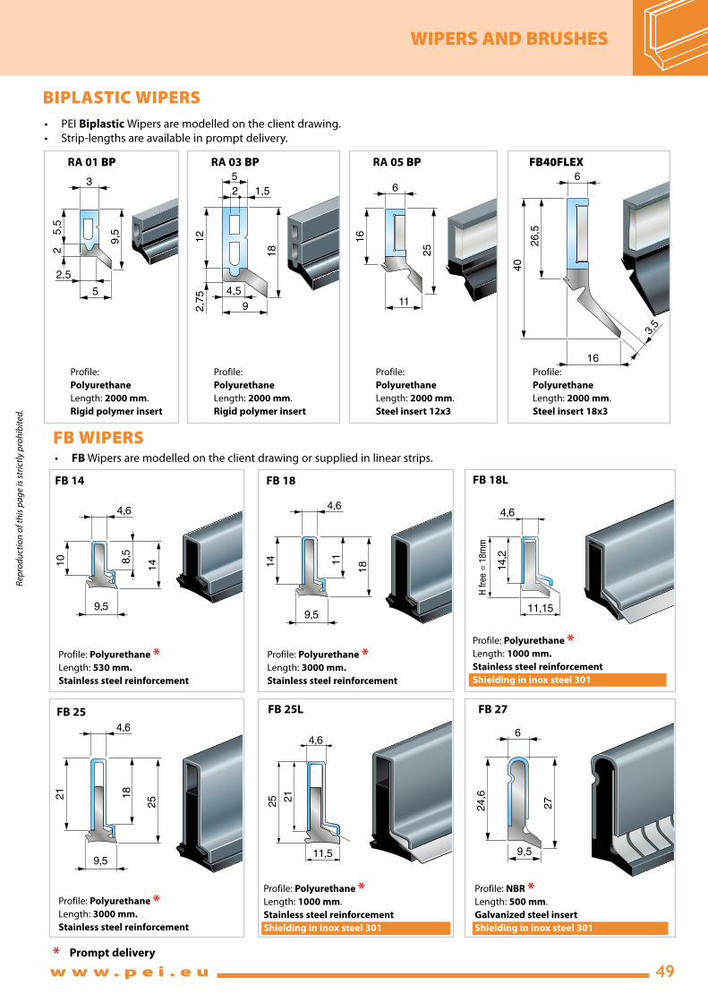
BIPLASTIC WIPERS
FB WIPERS
• PEIBiplastic Wipers are modelled on the client drawing.
• Strip-lengthsareavailableinpromptdelivery.
• FB Wipers are modelled on the client drawing or supplied in linear strips.
RA 01 BP RA 03 BP RA 05 BP FB40FLEX
Profile:
Polyurethane Length: 2000 mm.
Rigid polymer insert
Profile:
Polyurethane Length: 2000 mm.
Rigid polymer insert
Profile:
Polyurethane Length: 2000 mm.
Steel insert 12x3
Profile:
Polyurethane Length: 2000 mm.
Steel insert 18x3
5,5
2
9,5
3
2,5
5
12
2,7
5
18
2
5
1,5
4,5
9
16
25
6
11
26
,5
40
6
16
3,5
4,6
9,5
14 8,5
10
4,6
9,5
18 11
14
4,614,2
H f
ree =
18m
m
11,15
4,6
9,5
25 18
21
* Prompt delivery
Profile: Polyurethane *Length: 530 mm.
Stainless steel reinforcement
Profile: Polyurethane *Length: 3000 mm.
Stainless steel reinforcement
Profile: Polyurethane *Length: 3000 mm.
Stainless steel reinforcement
FB 14 FB 18 FB 18L
FB 25
6
9,5
27
24,6
FB 25L FB 27
Profile: Polyurethane *Length: 1000 mm.
Stainless steel reinforcement
Shielding in inox steel 301
Profile: Polyurethane *Length: 1000 mm.
Stainless steel reinforcement
Shielding in inox steel 301
Profile: NBR *Length: 500 mm.
Galvanized steel insert
Shielding in inox steel 301
25 21
4,6
11,5

50
WIPERS AND BRUSHES
w w w . p e i . e u
Rep
rod
uct
ion
of
this
pa
ge
is s
tric
tly
pro
hib
ited
.
7
13
4
1,5
1,3
11
20
7
22,5
Profile: NBR * or Viton®
Length: 560 mm.
Steel insert
Profile: NBR * or Viton® *Length: 560 mm.
Steel insert
Profile: NBR * or Viton®
Length: 560 mm.
Steel insert
9
16
6
21,5
RA B1 RA B2 RA B3
RA WIPERS
RA B WIPERS
RA Wipers are modelled on the client drawing or supplied in linear strips.
RA B Wipers are supplied exclusively in linear strips.
* Prompt delivery
* Prompt delivery
5
2,2
7
31
28
RA 06 RA 25L
Profile:
NBR * or Viton®
Length: 560 mm.
Steel insert
5
2,2
7
2117
,5
RA 04
Profile:
NBR * or Viton®
Length: 560 mm.
Steel insert
6
2,2
11
2521
RA 05
Profile:
NBR * or Viton® *Length: 560 mm.
Steel insert
2,5
1,3
5
9,5
7,5
Profile:
NBR * or Viton® *Length: 500 mm.
Steel insert
RA 01
5
2
9
1815
RA 03
Profile:
NBR * or Viton®
Length: 560 mm.
Steel insert
5
2
7
1512
RA 02
Profile:
NBR * or Viton® *Length: 560 mm.
Steel insert
Profile:
NBR * or Viton®
Length: 800 mm.
Steel insert
Thin metal protective plate in inox steel 301
Profile:
NBR *
Length: 800 mm.
Steel insert
Thin metal protective plate in inox steel 301
3,5
2
39
26,5
5
14,84
25,0
3
3,20
9,90
16,1
5
2
RA 39L

51
WIPERS AND BRUSHES
w w w . p e i . e u
Rep
rod
uct
ion
of
this
pa
ge
is s
tric
tly
pro
hib
ited
.
LINEAR BRUSHES WITH SUPPORT FRAME• Special shapes may be created
• The brush is easy to replace
• Thesupport frame is made of galvanized steel
• Prompt delivery in strips
WIPERS FOR TELESCOPIC STEEL COVERS
These types of wipers are normally applied to telescopic steel covers.
Codes RA B consists of a metal insert to which an NBR profile has been vulcanized.
Codes PR 2 and PR 3 has steel reinforcement and polyurethane profile.
Codes PR 4A and D can be instantly replaced on the telescopic cover, without disassembling the cover itself. They have a metal reinforcement with a seal designed to clean the cover.
8
12,5
6,2
4,3
1,5
12
18,5
7,7
5,8
2
32 11 21 17 14 9 9 18 1000 Nylon Ø 0,15
42 22 20 9 6 26 5 31 2000 Nylon Ø 0,15
72 40 32 15 10 40 10 50 2000 Nylon Ø 0,25
92 60 32 15 10 60 10 70 2000 Nylon Ø 0,50
112 80 32 15 10 80 10 90 2000 Nylon Ø 0,50
132 100 32 15 10 100 10 110 2000 Nylon Ø 0,50
40 20 20 9 6 24 5 29 2000 Brass Ø 0,15
70 50 20 9 6 54 5 59 2000 Brass Ø 0,15
100 80 20 9 6 84 5 89 2000 Brass Ø 0,15
SN1
SN2
SN3
SN4
SN5
SN6
S01
S02
S03
Code A B C D E F G H Length Bristle
PR 2 PR 312
17,5
7,3
2
9,8
12
17,5
7,3
2
9,8
PR 4A PR 4A D
D
FG
H
BC
A
E
• SoldONLYinstandardstrip-lengths.• EasyreplacementofwiperprofileforcodesPR2,PR3,PR4A and PR 4A - D.
• Thepolyurethaneprofileisdeliveredinsertedinthesteel
reinforcement.
* Prompt delivery in strips
PR 2 - PR 3 PR 4A PR 4A DRA B
Profile: Polyurethane *Length: 3000 mm.
Steel reinforcement
Profile: Polyurethane *
Length: 3000 mm.
Steel reinforcement
Profile: Polymeric GM2357
Length: 3000 mm.
Steel reinforcement
Profile: Polymeric GM2319
Length: 3000 mm.
Steel reinforcement
For working
with COOLANTS
For
DRYworking
MATERIALS
Heat Resistance
Synthetic Oil Resistance
Mineral Oil Resistance
Vegetable Oil Resistance
Wear Resistance
Momentarycontact
°C
Continuous°C
Excellent Good Poor Excellent Good Poor Excellent Good Poor Excellent Good Poor
NBR 250 -20÷+100 • • • •Polyurethane 200 -30÷+90 • • • •
VITON® 1000 -20÷+280 • • • •PolymericGM2319(red)
forworkingwithcoolants
200 -30÷+90 • • • •
PolymericGM2357(blue)fordryworking
280 -30÷+120 • • •

52
FABRIC MATERIAL LIST
w w w . p e i . e u
Rep
rod
uct
ion
of
this
pa
ge
is s
tric
tly
pro
hib
ited
.
• • 20 • 1 • 1,5 no
• • 20 • 1,5 • 2,5 5
• • 20 • 1,5 • 2,5 5
• • 20 • 1,8 • 3 5,5
• • 20 • 2,4 • 4 6,5
• • 20 • 3
• • 50 • 3,5
• • 50 • 3,5
• • 20 • 1,2 • 2 4,5
• • 20 • 1,5 • 5 10
• • 20 • • 1,5
• • 20
• • 70
• • 20 •
• • 20 • 2,1
• 70
• 90
• 150
• •52
• • 20 •
• • 20 •
• • 20
•
• • 70
• • 20 • 2,5
• • 70
• • 20 • • 1,5
• • 20 •
• • 20 •
• • 70
• • 70
• • 20 •
• • 20 • 2,1 • 3,5 6
• • 20 • 1,5 • 2,5 5
• • 20 •
• • 40
TEMAT001 Neoprene* Polyamide Neoprene* 0,3 250 -20+120
TEMAT002 Neoprene* Polyester Hypalon* 0,5 250 -20+120
TEMAT202 Neoprene* Polyester Neoprene* 0,5 250 -20+120
TEMAT003 Neoprene* Polyester Hypalon* 0,6 250 -20+120
TEMAT004 Neoprene* Polyester Hypalon* 0,8 250 -20+120
TEMAT005 Neoprene* Polyester Hypalon* 1,0 250 -20+120
TEMAT006 Neoprene* Polyester Hypalon* 1,2 250 -20+120
TEMAT007 Neoprene* Kevlar* Hypalon* 1,15 350 -20+120
TEMAT008 NBR Polyester NBR 0,33 250 -20+100
TEMAT009 Silicon Fiberglass Neoprene* 0,5 350 -60+250
TEMAT091 PVC Fiberglass PVC 0,44 300 -30+80
TEMAT102 Ptfe Fiberglass Ptfe 0,250 320 -200+260
TEMAT104 Ptfe Fiberglass Ptfe 0,7 320 -200+260
TEMAT106 Ptfe Polyester Polyurethane 0,32 200 -30+120
TEMAT011 Aluminium-carbonfabric 0,7 2500 -100+260
TEMAT012 AISI301Stainlesssteel 0,2 1200 -250+400
TEMAT013 AISI301Stainlesssteel 0,3 1200 -250+400
TEMAT014 AISI301Stainlesssteel 0,4 1200 -250+400
TEMAT122 304StainlesssteelPolyester0,81200-25+300
TEMAT015 Polyurethane Polyester Polyurethane 0,25 200 -30+90
TEMAT151 Polyurethane Polyester Polyurethane 0,35 200 -30+90
TEMAT152 Polyurethane Polyester Polyurethane 0,8 200 -30+90
TEMAT153 Polyurethane - - 0,5 200 -30+70
TEMAT160 Polyester Fabric 1,4 200 -30+90
TEMAT161 Polyurethane Polyester Fabric 0,8 200 -30+90
TEMAT162 Polyurethane Polyester Fabric 1,4 200 -30+90
TEMAT164 Polyurethane Kevlar* Polyurethane 0,35 350 -30+180
TEMAT165 Polyurethane Nomex* Polyurethane 0,36 300 -30+130
TEMAT169 Polyurethane Panox*/Kevlar*Polyurethane 0,33 300 -30+130
TEMAT170 Polyurethane Polyester Fabric 1,6 200 -30+90
TEMAT180 CPT** Polyester - 1,6 1200 -25+300
TEMAT017 PVC Polyester PVC 0,36 100 -30+70
TEMAT018 PVC Polyester PVC 0,7 100 -30+70
TEMAT019 PVC Polyester PVC 0,5 100 -30+70
TEMAT020 PVC Polyester PVC 0,25 100 -30+70
TEMAT022 PVC PVC 1,4 100 -30+70
*Neoprene,Hypalon,Kevlar,PanoxandNomexareregisteredDuponttrademarks.
**CeramicPolymerTechnology
Co
de
Vis
ible
sid
e
Fa
bri
c in
se
rt
Hid
de
n s
ide
Th
ick
ne
ss
Mo
me
nta
ryc
on
tac
t °C
Co
nti
nu
ou
s°C
Ma
teri
al s
uit
ab
lefo
r c
ov
er
wit
ho
ut
ca
nis
ter
Ma
teri
al s
uit
ab
lefo
r c
ov
er
wit
h c
an
iste
r
Min
win
din
gd
iam
ete
r m
m
Su
ita
ble
ma
teri
al
Su
ita
ble
ma
teri
al
Su
ita
ble
ma
teri
al
Th
ick
ne
ss
of
1 f
old
(S
P)
mm
Th
ick
ne
ss
of
1 f
old
(S
P)
mm
Wit
h lo
ng
itu
din
al
se
am
thic
kn
es
s o
f 1
fold
(S
P)
mm
Description of materials Heat resistance Roll-up Covers Thermic welded flat covers
Sewn roundbellows
Heat-formed roundbellows
Resistswater,oil,coolant,dilutedacids,petroleumproducts,atmosphericagentsandozone.Fairshearstrengthandabrasionresistance.
Resistswater,oil,coolant,dilutedacids,petroleumproducts,atmosphericagentsandozone.Goodshearstrengthandabrasionresistance.Hypalonisespeciallyresistanttoseawater.
Samecharacteristicsasabove(from001to006).Kevlarhasexcellentshearstrength.Normallyusedwhenthereisheavymechanicalstress,heavyconcentrationofsharpshavings,andhightemperatures.
Excellentresistancetomineralandvegetableoils,hydrocarbons,waterandgas.Goodmechanicalproperties.Normallyusedinthefoodindustrysinceappropriateforusearoundoil,grease,blood,etc.
Especiallysuitedtohighandlowtemperatures.Fiberglasshasstrongtemperatureresistance,butpoormechanicalstrength.Siliconeisanexcellentanti-adhesiveandresistschlorides,solvents,UVraysandozone.
Fabricappropriateforusearoundsmallweldsplatter.Alsosuitableforusearoundacids.
Workareaswithheavyconcentrationofacids.Highlyanti-adhesivesurface.Lowfrictioncoefficient.Chemicallyinert.Resistsformationofmoldandfungus.Non-toxic.Highlylimitedthermalexpansion.TransparenttomicrowavesandUVrays.TeflonissuitableforallacidsexceptSODIUM-POTASSIUM-FLUORIDEattemperaturesbeginningat150 C.
Excellentresistancetooilsandchemicalproducts.Noadhesivesurface.Lowfrictioncoefficient.Excellentchemicalinertia.Excellentresistancetoabrasionandbendingresistance.
bynature.Carbonfibersresistupto2500°Cforshortperiods.Excellentmechanicalstrength.Thealuminum-coatingreflectsradiantheat.Resistsheavyweldsplatterandmoltenmetal;mainlyusedinfoundries.
Usedforharshworkingenvironmentswithheavyconcentrationsofsharpshavingsandhightemperatures.Excellentresistancetoacids.
Goodresistancetopetroleumproducts,oilsandheavyabrasion.Excellentbendingstrength.
Goodresistancetopetroleumproducts,oilsandfairabrasionresistance.Usedformanufacturingthermic-weldedroundbellows.
Goodresistancetopetroleumproducts,oilsandheavyabrasion.Thetwo-plyfabricinsertgiveshightransverserigidityandattractiveappearance.
Normallyusedaroundlargequantitiesofshavings.Notsuitablefordryusewithhotshavings.
Goodresistancetopetroleumproducts,oilsandheavyabrasion.Goodtransverserigidity.Normallyusedaroundmediumquantitiesofshavings.Notsuitablefordryusewithhotshavings.
Goodresistancetopetroleumproducts,oilsandheavyabrasion.Thetwo-plyfabricinsertgiveshightransverserigidityandattractiveappearance.Normallyusedaroundlargequantitiesofshavings.Notsuitablefordryusewithhotshavings.
Goodresistancetopetroleumproducts,oilsandheavyabrasion.Excellentbendingstrength.Excellentmechanicalstrength;Kevlarhasexcellentshearstrength.Normallyusedwhenthereisheavyconcentrationofsharpshavings,andhightemperatures.
Goodresistancetopetroleumproducts,oilsandheavyabrasion.Excellentbendingstrength.Excellentmechanicalstrength.Goodresistancetosmallweldsplatterorhotmaterial.Widelyusedinlasercuttingmachines.
Mainlyusedaroundheavyambientdust,smallsplatterofcoolantandoil.Alsoappropriateforusearoundacids.
Thismaterialconsistsofhigh-strengthpolyesternettingwithagridof20x20mm.Itisusedforspecialapplications.Wecanprovideothertypesofnettingswithdifferentthicknessand/orgrid.
PolyesterNet
GreyPolyurethane

53
FABRIC MATERIAL LIST
w w w . p e i . e u
Rep
rod
uct
ion
of
this
pa
ge
is s
tric
tly
pro
hib
ited
.
CERAMIX has an excellent abrasion resistance and excellent shear strength. CERAMIX shows excellent resistance to mineral oils and hot temperatures. The two-ply fabric insert gives an high transverse rigidity and a very attractive appearance. CERAMIX is used when large quantities of hot and shearing shavings are produced, in cases of high speed chip-removing in wet and dry work environments. ANTISTATIC-PROOF AND SELF-EXTINGUISHING.
• • 20 • 1 • 1,5 no
• • 20 • 1,5 • 2,5 5
• • 20 • 1,5 • 2,5 5
• • 20 • 1,8 • 3 5,5
• • 20 • 2,4 • 4 6,5
• • 20 • 3
• • 50 • 3,5
• • 50 • 3,5
• • 20 • 1,2 • 2 4,5
• • 20 • 1,5 • 5 10
• • 20 • • 1,5
• • 20
• • 70
• • 20 •
• • 20 • 2,1
• 70
• 90
• 150
• •52
• • 20 •
• • 20 •
• • 20
•
• • 70
• • 20 • 2,5
• • 70
• • 20 • • 1,5
• • 20 •
• • 20 •
• • 70
• • 70
• • 20 •
• • 20 • 2,1 • 3,5 6
• • 20 • 1,5 • 2,5 5
• • 20 •
• • 40
Neoprene* Polyamide Neoprene* 0,3 250 -20+120
Neoprene* Polyester Hypalon* 0,5 250 -20+120
Neoprene* Polyester Neoprene* 0,5 250 -20+120
Neoprene* Polyester Hypalon* 0,6 250 -20+120
Neoprene* Polyester Hypalon* 0,8 250 -20+120
Neoprene* Polyester Hypalon* 1,0 250 -20+120
Neoprene* Polyester Hypalon* 1,2 250 -20+120
Neoprene* Kevlar* Hypalon* 1,15 350 -20+120
Polyester NBR 0,33 250 -20+100
Silicon Fiberglass Neoprene* 0,5 350 -60+250
PVC Fiberglass PVC 0,44 300 -30+80
Ptfe Fiberglass Ptfe 0,250 320 -200+260
Ptfe Fiberglass Ptfe 0,7 320 -200+260
Ptfe Polyester Polyurethane 0,32 200 -30+120
Aluminium-carbonfabric 0,7 2500 -100+260
AISI301Stainlesssteel 0,2 1200 -250+400
AISI301Stainlesssteel 0,3 1200 -250+400
AISI301Stainlesssteel 0,4 1200 -250+400
304StainlesssteelPolyester0,81200-25+300
Polyurethane Polyester Polyurethane 0,25 200 -30+90
Polyurethane Polyester Polyurethane 0,35 200 -30+90
Polyurethane Polyester Polyurethane 0,8 200 -30+90
Polyurethane - - 0,5 200 -30+70
Polyester Fabric 1,4 200 -30+90
Polyurethane Polyester Fabric 0,8 200 -30+90
Polyurethane Polyester Fabric 1,4 200 -30+90
Polyurethane Kevlar* Polyurethane 0,35 350 -30+180
Polyurethane Nomex* Polyurethane 0,36 300 -30+130
Polyurethane Panox*/Kevlar*Polyurethane 0,33 300 -30+130
Polyurethane Polyester Fabric 1,6 200 -30+90
CPT** Polyester - 1,6 1200 -25+300
PVC Polyester PVC 0,36 100 -30+70
PVC Polyester PVC 0,7 100 -30+70
PVC Polyester PVC 0,5 100 -30+70
PVC Polyester PVC 0,25 100 -30+70
PVC PVC 1,4 100 -30+70
*Neoprene,Hypalon,Kevlar,PanoxandNomexareregisteredDuponttrademarks.
**CeramicPolymerTechnology
Co
de
Primary resistance characteristics
Resistswater,oil,coolant,dilutedacids,petroleumproducts,atmosphericagentsandozone.Fairshearstrengthandabrasionresistance.
Resistswater,oil,coolant,dilutedacids,petroleumproducts,atmosphericagentsandozone.Goodshearstrengthandabrasionresistance.Hypalonisespeciallyresistanttoseawater.
Samecharacteristicsasabove(from001to006).Kevlarhasexcellentshearstrength.Normallyusedwhenthereisheavymechanicalstress,heavyconcentrationofsharpshavings,andhightemperatures.
Excellentresistancetomineralandvegetableoils,hydrocarbons,waterandgas.Goodmechanicalproperties.Normallyusedinthefoodindustrysinceappropriateforusearoundoil,grease,blood,etc.
Especiallysuitedtohighandlowtemperatures.Fiberglasshasstrongtemperatureresistance,butpoormechanicalstrength.Siliconeisanexcellentanti-adhesiveandresistschlorides,solvents,UVraysandozone.
Fabricappropriateforusearoundsmallweldsplatter.Alsosuitableforusearoundacids.Self-extinguishing.
Workareaswithheavyconcentrationofacids.Highlyanti-adhesivesurface.Lowfrictioncoefficient.Chemicallyinert.Resistsformationofmoldandfungus.Non-toxic.Highlylimitedthermalexpansion.TransparenttomicrowavesandUVrays.TeflonissuitableforallacidsexceptSODIUM-POTASSIUM-FLUORIDEattemperaturesbeginningat150°C.
Excellentresistancetooilsandchemicalproducts.Noadhesivesurface.Lowfrictioncoefficient.Excellentchemicalinertia.Excellentresistancetoabrasionandbendingresistance.Mainly used in grinding machines.
Self-extinguishing bynature.Carbonfibersresistupto2500°Cforshortperiods.Excellentmechanicalstrength.Thealuminum-coatingreflects radiantheat.Resistsheavyweldsplatterandmoltenmetal;mainlyusedinfoundries.
Usedforharshworkingenvironmentswithheavyconcentrationsofsharpshavingsandhightemperatures.Excellentresistancetoacids.
Goodresistancetopetroleumproducts,oilsandheavyabrasion.Excellentbendingstrength.
Goodresistancetopetroleumproducts,oilsandfairabrasionresistance.Usedformanufacturingthermic-weldedroundbellows.
Goodresistancetopetroleumproducts,oilsandheavyabrasion.Thetwo-plyfabricinsertgiveshightransverserigidityandattractiveappearance.
Normallyusedaroundlargequantitiesofshavings.Notsuitablefordryusewithhotshavings.Static-proof.
Goodresistancetopetroleumproducts,oilsandheavyabrasion.Goodtransverserigidity.Normallyusedaroundmediumquantitiesofshavings.Notsuitablefordryusewithhotshavings.
Goodresistancetopetroleumproducts,oilsandheavyabrasion.Thetwo-plyfabricinsertgiveshightransverserigidityandattractiveappearance.Normallyusedaroundlargequantitiesofshavings.Notsuitablefordryusewithhotshavings.Static-proof.
Goodresistancetopetroleumproducts,oilsandheavyabrasion.Excellentbendingstrength.Excellentmechanicalstrength;Kevlarhasexcellent shearstrength.Normallyusedwhenthereisheavyconcentrationofsharpshavings,andhightemperatures.
Goodresistancetopetroleumproducts,oilsandheavyabrasion.Excellentbendingstrength.Excellentmechanicalstrength.Goodresistancetosmallweldsplatterorhotmaterial.Widelyusedinlasercuttingmachines.Self-extinguishing.
Excellent resistance to petroleum products, oils and heavy abrasion; high abrasion resistance; excellent mechanical strength and bending strength. Good resistance to small weld splatter or hot material; at present considered the best commercial material to be used in laser cutting machines. Self-extinguishing.
Excellent resistance to petroleum products, oils and heavy abrasion. The two-ply fabric insert gives a very high transverse rigidity and an attractive appearance. Normally used around large quantities of shavings. We recommend the constant use of coolant. SELF-EXTINGUISHING FABRIC.
Mainlyusedaroundheavyambientdust,smallsplatterofcoolantandoil.Alsoappropriateforusearoundacids.
Thismaterialconsistsofhigh-strengthpolyesternettingwithagridof20x20mm.Itisusedforspecialapplications.Wecanprovideothertypesofnettingswithdifferentthicknessand/orgrid.
PolyesterNet
GreyPolyurethane
TEMAT001
TEMAT002
TEMAT202
TEMAT003
TEMAT004
TEMAT005
TEMAT006
TEMAT007
TEMAT008
TEMAT009
TEMAT091
TEMAT102
TEMAT104
TEMAT106
TEMAT011
TEMAT012
TEMAT013
TEMAT014
TEMAT122
TEMAT015
TEMAT151
TEMAT152
TEMAT153
TEMAT160
TEMAT161
TEMAT162
TEMAT164
TEMAT165
TEMAT169
TEMAT170
TEMAT180
TEMAT017
TEMAT018
TEMAT019
TEMAT020
TEMAT022
STEEL-TEX is a the stainless steel roll-up cover with polyurethane. It is cut resistant on impact with incandescent and sharp metal
shavings and offers exceptional resistance during dry working or with coolants.
It is compact, weighs 0.9 kg per sq.m and is 0.8mm thick and can be installed on the entire range of P.E.I. roll-up covers.

54 w w w . p e i . e u
APPLICATIONS
Rep
rod
uct
ion
of
this
pa
ge
is s
tric
tly
pro
hib
ited
.

55w w w . p e i . e u
APPLICATIONS
Rep
rod
uct
ion
of
this
pa
ge
is s
tric
tly
pro
hib
ited
.