template matching using dsp slices on the fpga · template matching using dsp slices on the fpga...
TRANSCRIPT

Template Matching using DSP slices on the FPGA
Kaoru Hashimoto, Yasuaki Ito, Koji NakanoDepartment of Information Engineering
School of Engineering, Hiroshima University1-4-1 Kagamiyama, Higashi-Hiroshima, 739-8527, JAPAN
Abstract—The main contribution of this paper is to proposean FPGA implementation of template matching using DSPslices. Template matching is a technique for finding small partsof an image which match a template image. In our approach,we use a pixel rearrangement technique that is a coarse-to-finetechnique. Unlike ordinary coarse-to-fine techniques, it alwayscan find a template image in a base image if the templateimage is included in the base image. In our implementation,we use multiple matching modules that compute similarityand work in parallel. In each matching module, we efficientlyuse embedded DSP slices on the Virtex-6 FPGA. We haveimplemented the template matching in a Xilinx Virtex-6 FPGAXC6VLX240T-FF1156. The implementation results show thatit can be implemented in the FPGA with 352 DSP slices, 3 blockRAMs and 455 CLBs. It runs in approximately 280MHz clockfrequency. The computing time of our FPGA implementationis 348.88 and 3.66 times faster than that of CPU and GPUimplementations, respectively.
Keywords-Template matching, FPGA, DSP slice, Block RAM,Pipeline, Parallel processing
I. INTRODUCTION
A Field Programmable Gate Array (FPGA) is a logicdevice that can provide programmability for customers toimplement their own logic. Since FPGA chip maintains rel-ative lower price and its programmable features, it is widelyused in those fields which need to update architecture orfunctions frequently such as communication and educationareas. The most common FPGA architecture consists ofan array of logic blocks, I/O pads, and routing channels.Furthermore, resent FPGAs have embedded DSP slices andblock RAMs that make a higher performance and broaderapplications. They are widely used not only in consumerand industrial products but also in academic research foraccelerating processor intensive algorithms [1]–[7].
The Xilinx Virtex-6 series FPGAs have DSP48E1 slicesequipped with a multiplier, adders, logic operators, etc [8].More specifically, as illustrated in Figure 1, the DSP48E1slice has a two-input multiplier followed by multiplexers anda three-input adder/subtractor/accumulator. The DSP48E1multiplier can perform multiplication of an 18-bit and a25-bit two’s complement numbers and produce one 48-bit two’s complement production. Programmable pipeliningof input operands, intermediate products, and accumulatoroutputs enhances throughput and improves the frequency.The DSP48E1 also has pipeline registers between operatorsto reduce the delay. The Xilinx FPGA XC6VLX240T has768 DSP48E1 slices arranged in 8 columns of 96 adjacentDSP48E1 slices. Neighboring DSP48E1 slices are connected
directly through pipeline registers that are not show inthe figure. The block RAM in the Virtex-6 FPGA is anembedded memory supporting synchronized read and writeoperations. In Virtex-6 FPGAs, it can be configured as a36k-bit dual-port RAMs, FIFOs, or two 18k-bit dual-portRAMs.
Template matching is one of the techniques for detectinga given template image from an image called a base image,and examining whether the template exists in the baseimage to be detected. It is widely used for industrial man-ufacturing, robot navigation, geographical research, imageregistration, etc [9]–[12]. Figure 2 shows an example oftemplate matching. Given a template image and base image,template matching is to find a position such that a subimagein the base image is the most similar to the template image.There are some measurements of the similarity between atemplate image and a subimage of the base image. In thispaper, we use the normalized correlation coefficient as thesimilarity measure [13]. It is a normalized measurement withthe average and standard deviation of a template image anda base image.
To reduce the computing time of template matching,numerous methods have been developed. One of the mostfamous methods is coarse-to-fine template matching [9],[14]–[16]. It locates a low-resolution template image intothe low-resolution base image, and then refines the searchat higher resolution levels. In this algorithm, it is importantto make low-resolution images because the low-resolutiontemplate image is not always found in the low-resolutionbase image. For example, let us consider the case that alow-resolution image is made by sampling every two pixels.When a base image and a template image are checkeredpatterns as shown in Figure 3, their low-resolution imagesmay be different from each other. Although the base imageincludes the template image, it occurs that the templatematching may be fault. To avoid such faults by sampling,blurred low-resolution images are made by low-pass filtersuch as Gaussian filter, Laplacian filter, wavelet transform,and so on [17]–[22]. However, it is not always possible tofind the low-resolution template image. On the other hand, toaccelerate the speed of template matching, various methodssupported by hardware acceleration with GPUs [16], [21],[23]–[25] and FPGAs [5], [26] have been presented.
Paper [16] shows a template matching algorithm withpixel rearrangement. This algorithm is based on the coarse-to-fine template matching. Unlike usual coarse-to-fine al-gorithms, however, the feature of this algorithm is that if

������
× ����� �����
������������ ������������� !"#$%&!'(&)!*)+,()- !'&)!
.$/&,-/, !��� !0 +,#& !
Figure 1. Architecture of DSP48E1
(b) Template image
(a) Base image (c) The result of template matching
Figure 2. Example of Template Matching
Base image
Samplingevery
two pixels
Low-resolutionbase image
Template image
Low-resolutiontemplate image
Figure 3. Low-resolution images by sampling
a template image is included in a base image, this algo-rithm always can find the template. In this algorithm, low-resolution images by rearranging pixels of the base image aregenerated. In the existing sampling-based algorithms, onelow-resolution base and template images are generated, andtemplate matching is performed for them. On the other hand,this algorithm generates k2 low resolution base images bysampling every k pixels. The sampling is performed for thebase image shifted pixel by pixel from 0 to k − 1 pixels.Therefore, in our algorithm, given an n× n base image, k2
sampled base images whose size is nk × n
k are generated.More specifically, let I ′s,t (0 ≤ s, t ≤ k − 1) be k2 sampledbase images, and they are sampled from a base image suchthat each sampled image is
I ′s,t(x, y) = I(kx + s, ky + t) (0 ≤ x, y ≤ n
k− 1).
Figure 4 shows an example of sampling for k = 3. Sincethe size of a base image is 6×6, k2 sampled images of size2 × 2 are generated. The readers should have no difficultyto confirm that the size of a base image is equal to thetotal size of the k2 sampled images. Therefore, we can saythat our sampling manner is equivalent to rearrangementof a template image. Also, a template image is reducedby sampling every k pixels. Although the base image andtemplate image are checkered patterns shown in Figure 3,at least one low-resolution image includes the same patternas the low-resolution base image. In other words, if theoriginal base image includes the original template image,it is always to find it in one of the low-resolution imagesusing template matching with pixel rearrangement. Afterthat, we perform template matching for the low-resolutiontemplate image and each sampled base image. Form theresults thus obtained, template matching is performed forthe corresponding positions in the original base image andtemplate image.
1 2 34 5 67 8 9
1 2 34 5 67 8 9
1 2 34 5 67 8 9
1 2 34 5 67 8 9
1 11 1
2 22 2
3 33 3
4 44 4
5 55 5
6 66 6
7 77 7
8 88 8
9 99 9
Base image 9 sampled images
Figure 4. Pixel rearrangement for k = 3
The main contribution of this paper is to present a new im-plementation of template matching. Our new idea includes:(1) Pixel rearrangement: Our template matching circuitis based on the idea of the pixel rearrangement method asshown the above. The difference is that in our proposedapproach, a template image is rearranged. On the other hand,in the original pixel rearrangement method, a base imageis rearranged instead of a template image. However, thereaders can easily find that there is no difference between
them in essence. Namely, this algorithm is a coarse-to-finetemplate matching and if a template image is included in abase image, it always can find the template, too. Samplinga template image, the template matching is performed fora low-resolution base image and k2 template low-resolutionimages. In our implementation, k2 template matching mod-ules are implemented and work in parallel. (2) Use of DSPslices and block RAMs: DSP slices are used to compute thesimilarity between a low-resolution base image and templateimages. DSP slices basically perform multiplication andaccumulation to compute the dot-product. They are directlyconnected and work pipeline fashion. Also, we avoid thecomputation of square by pre-loading them into the blockRAMs as look-up-tables.
Using these ideas, we have evaluated the performanceof our template matching circuit using the Xilinx Virtex-6 family FPGA XC6VLX240T-FF1156. The implementedcircuit can perform the template matching for n = 1024,m = 16, and k = 4. Namely, the sizes of a base image anda template image are 1024×1024 and 16×16, respectively.Also, the sizes of the low-resolution base and templateimages are 256 × 256 and 4 × 4, respectively. The readersmay think that the size of the template image is too small.However, by sampling the base image and the templateimage beforehand or using a part of the template image asa template image, we can perform the template matchingfor larger template images [20]. We note that our proposedimplementation performs the template matching only for thelow-resolution images. This is because in [16], the ratioof the computing time for the low-resolution images tothe whole computing time is more than 95%. The keyto accelerate the whole computing time is to shorten therunning time for the low-resolution images. Therefore, inour implementation, we suppose the other processes areperformed by another processor, for example, an embeddedprocessor in the same FPGA, a host PC connected to theFPGA, or etc. According to the results of our evaluation, weachieved speed-up factors of 348.88 and 3.66, respectively.
The remainder of this paper is organized as follows:Section II introduces the similarity between two images.In Section III, we show the template matching with pixelrearrangement. The FPGA implementation using DSP slicesand block RAMs is shown in Section IV. Section V exhibitsthe performance of our proposed algorithm on the FPGA.Finally, Section VI offers concluding remarks.
II. THE IMAGE SIMILARITY BETWEEN A TEMPLATEIMAGE AND A BASE IMAGE
The main purpose of this section is to define the similarityR(T, I) for a template image T and a base image I to clarifyour work in this paper. There are many measurements ofthe similarity in template matching. In this paper, we usethe normalized correlation coefficient as the similarity [13].The normalized correlation coefficient is used to measure thecorrelation between two variables. We use it to evaluate thesimilarity of a template image and a base image in templatematching as follows.
First, let us define the similarity of two images A andB of the same size. For simplicity, we assume that theyare square, that is, the size of two images is m × m. LetA(i, j) and B(i, j) denote the intensity level of an (i, j)pixel (0 ≤ i, j ≤ m − 1) of A and B, respectively. Thenormalized correlation coefficient R(A,B) between the twoimages A and B is computed by the following formula:
R(A,B) =∑
(A(i, j) − A)(B(i, j) − B)√∑(A(i, j) − A)
∑(B(i, j) − B)
, (1)
where A = 1m2
∑A(i, j) and B = 1
m2
∑B(i, j) are the av-
erage pixel values of A and B, respectively. The normalizedcorrelation coefficient R(A,B) takes a real number in therange [−1, +1]. Larger value of the normalized correlationcoefficient implies that two images A and B are moresimilar. It should be clear that the normalized correlationcoefficient R(A,B) can be computed in O(m2) time by asequential algorithm in an obvious way.
Suppose that a base image I and a template image T aregiven. Let n × n and m × m (n > m) be the size of abase image I and a template image T , respectively. Also,let I(x, y) and T (x, y) denote the intensity levels of (x, y)pixels in I and T , respectively. Let I[x, y] (0 ≤ x, y,≤n − m) denote an m × m subimage of I that includes allpixels I(i′, j′) (x ≤ i′ ≤ x+m−1 and y ≤ j′ ≤ y+m−1).We define the similarity R(T, I) between a template T anda base image I as follows:
R(T, I) = max0≤x,y≤n−m
R(T, I[x, y]).
Clearly, R(T, I) is larger if I has a more similar subimageto T . Also, the position (x, y) that gives the maximum valueof R(T, I[x, y]) corresponds to the most similar subimageI[x, y] to the template image T . Let us evaluate the com-puting time necessary to compute R(T, I) and the mostsimilar position R(T, I) by a sequential algorithm. For anm×m template image T and a subimage I[x, y], the valueof R(T, I[x, y]) can be computed in O(m2) time. Hence, theevaluation of R(T, I[x, y]) for all I[x, y] (0 ≤ x, y ≤ n−m)takes (n − m + 1)2 × O(m2) = O(n2m2) time.
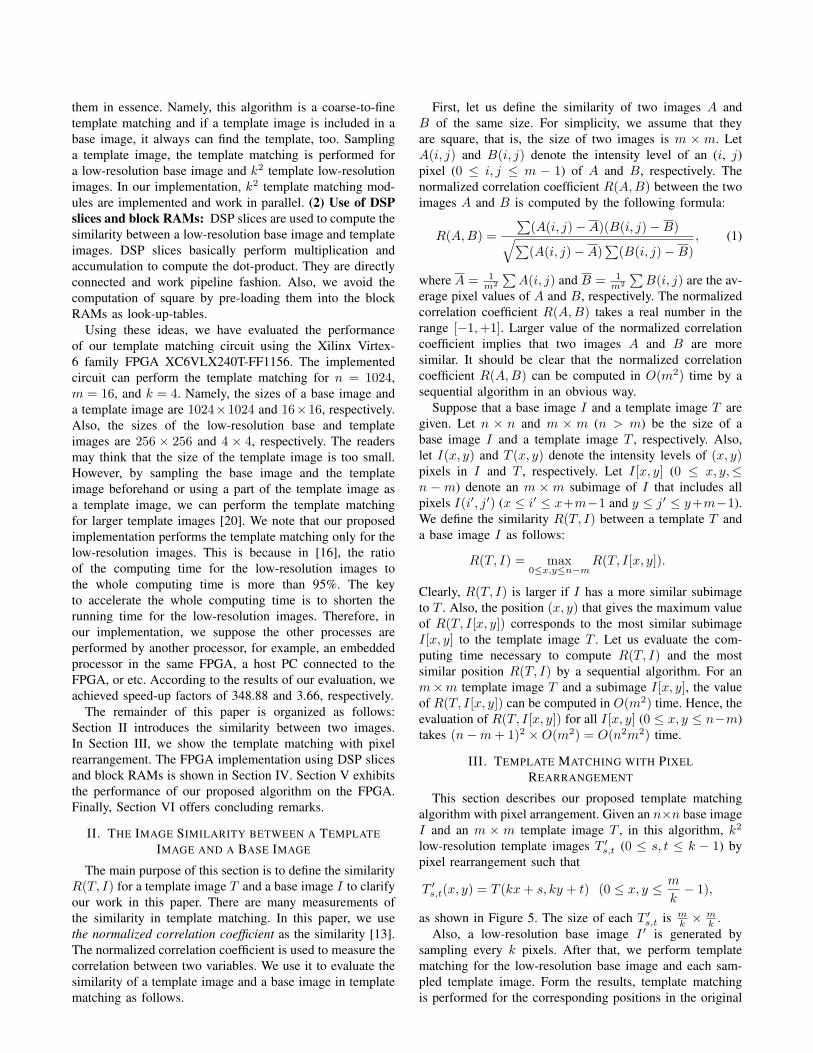
III. TEMPLATE MATCHING WITH PIXELREARRANGEMENT
This section describes our proposed template matchingalgorithm with pixel arrangement. Given an n×n base imageI and an m × m template image T , in this algorithm, k2
low-resolution template images T ′s,t (0 ≤ s, t ≤ k − 1) by
pixel rearrangement such that
T ′s,t(x, y) = T (kx + s, ky + t) (0 ≤ x, y ≤ m
k− 1),
as shown in Figure 5. The size of each T ′s,t is m
k × mk .
Also, a low-resolution base image I ′ is generated bysampling every k pixels. After that, we perform templatematching for the low-resolution base image and each sam-pled template image. Form the results, template matchingis performed for the corresponding positions in the original

T’0,0 T’1,0 T’k-1,0
T’0,1 T’1,1 T’k-1,1
T’0,k-1 T’1,k-1 T’k-1,k-1
k2 low-resolution template images
Template image T
(0,0) (1,0) (k-1,0)
(0,1) (1,1) (k-1,1)
(0,k-1) (1,k-1) (k-1,k-1)
Figure 5. Pixel rearrangement
base image. When an n × n base image and an m × mtemplate image are given, our proposed template matchingalgorithm with pixel rearrangement works as follows.Template Matching Algorithm with Pixel Rearrangement
Step 1. A low-resolution base image I ′ is generated bysampling every k pixels from a base image. Afterthat, k2 low-resolution template images T ′
s,t (0 ≤s, t ≤ k−1) are generated by pixel rearrangement.
Step 2. For each T ′s,t, the similarity R(T ′
s,t, I′) is com-
puted. If the similarity is larger than a thresholdvalue t, its coordinate makes a candidate positionfor the next step.
Step 3. The candidate positions are transformed to corre-sponding positions in the original base image. Foreach position, the similarity between original baseimage and the template image is computed.
Step 4. The position that has the largest similarity isoutput as the result.
The details of each step are shown, as follows.Step 1: In this step, a low-resolution base image I ′ is
generated by sampling every k pixels from an n × n baseimage. Since the size of I ′ is n
k × nk , it takes O(n2
k2 )-time.After that, to obtain k2 low-resolution template images T ′
s,t
(0 ≤ s, t ≤ k − 1), pixel rearrangement is performed suchthat
T ′s,t(x, y) = T (kx + s, ky + t) (0 ≤ x, y ≤ m
k− 1),
as shown in Figure 5. The size of each T ′s,t is m
k × mk .
Since the above operation is just rearranging pixels in thebase image, its computing time is O(m2).
Step 2: In Step 2, template matching between the low-resolution base image I ′ and each low-resolution templateimage T ′
s,t is performed, that is computing similaritiesR(T ′
s,t, I′) (0 ≤ s, t ≤ k − 1). In the template matching,
if the similarity is larger than a certain threshold t, itscoordinate is stored as a candidate position for the nextstep. Since the sizes of each low-resolution base imageand the low-resolution template image are n
k × nk and
mk ×m
k , O(n2m2
k4 )-time is necessary to perform each templatematching. Since there are k2 low-resolution template images,this step takes O(n2m2
k2 ) in total.Step 3: In this step, the candidate positions are trans-
formed to corresponding positions in the original base im-
age. We assume that the number of the candidate positionsis l found in Step 2 and let pi = (xi, yi) (1 ≤ i ≤ l)be the transformed candidate positions. For each pi, tem-plate matching is performed, that is computing similaritiesR(T, I[xi, yi]). It takes O(m2)-time to perform the templatematching for each pi. Therefore, the total computing timein this step is O(lm2).
Step 4: In Step 4, the maximum similarity position inStep 3 is output as the result. To find the maximum positionfrom l candidates, it takes O(l)-time.
According to the above, the total running time isO(n2m2
k2 + lm2). If l is small, it is close to O(n2m2
k2 ). Wenote that the above algorithm is different from the originalalgorithm in [16]. In the original algorithm, a base image isrearranged instead of a template image. On the other hand,in our approach, a template image is rearranged. However,the readers can easily find that there is no difference betweenthem in essence and the time complexity is exactly the same.
IV. FPGA IMPLEMENTATION
This section describes the architecture of our templatematching. The main idea of our architecture is to intro-duce pixel rearrangement and utilize DSP slices and blockRAMs in Xilinx Virtex-6 FPGA. We use Xilinx Virtex-6 family FPGA XC6VLX240T-FF1156 as the target de-vice [8]. It consists of columns of Configurable Logic Blocks(CLBs) each of which includes two slices, programmableInput/Output Blocks (IOBs), DSP48E1 slices, and 36k-bitdual-port block RAMs.
We note that our proposed implementation performs theprocess in Step 2 shown in Section III. This is becausein [16], the ratio of the computing time of Step 2 to thewhole computing time is more than 95%. The key to shortenthe whole computing time is to shorten the running timeof Step 2. Therefore, in our implementation, we supposethe other processes are performed by another processor, forexample, an embedded processor in the same FPGA, a hostPC connected to the FPGA, or etc.
The idea of our architecture is to perform the compu-tation of R(T ′
s,t, I′) simultaneously. Figure 6 illustrates an
outline of our architecture. Our architecture mainly consistsof line buffers, sum module, squared sum module, andk2 template matching units. In our architecture, k2 low-resolution template images, and threshold value are givenbeforehand. After that pixels in an input low-resolutionbase image in raster scan order are input for each clockcycle one by one. For each subimage of size m
k × mk , the
circuit performs template matching between the subimageand k2 low-resolution template images. As illustrated in thefigure, using one template matching unit, template matchingfor each low-resolution template image is performed andthey work in parallel. Also, our circuit is a fully pipelinedarchitecture. Given a pixel in raster scan order, the resultof the template matching for the subimage is output afterseveral clock cycles. In the followings, we will show thedetails of each module.

Line buffers
Base image I'
���������
���
������� ���
��� ������
��� ��� ������
Threshold tTemplateimage T'
k2
matchingresults���
���� ��� ������������� ��
�����������������
���������Figure 6. Outline of our architecture
A. Line buffers
Since pixels of the low-resolution base image are input inraster scan order, it is necessary to supply m
k × mk subimages
for the pixels. To active it, we use line buffers illustrated inFigure 7. The line buffers consist of m
k − 1 FIFOs (First InFirst Out). Each FIFO is composed of a block RAM andstores n
k pixels in a row of the low-resolution base image.
FIFO
FIFO
FIFO
FIFO
...
Inputpixels
��pixels
��pixels
Figure 7. Line buffers with mk
− 1 FIFOs
B. Sum module
Figure 8 illustrates the circuit that computes ΣI ′. Givenmk pixels from line buffers, the total of pixel values in I ′
is computed using two adder trees and mk shift registers for
each clock cycle.
Adder tree > > >
>
Adder tree
�������� �� ���Figure 8. Sum module for ΣI′
C. Squared-sum module
Figure 9 illustrates the circuit that computes ΣI ′2. In this
module, given mk pixels from line buffers, each pixel value
is squared. To square it, we take a look-up-table (LUT)using a block RAM. In the block RAM, the value of xis stored in the address of x in advance. Using the blockRAM, the number of DSP slices is reduced. Using the LUT,squared values are computed. After that, the total of themis computed using two adder trees and m
k shift registers foreach clock cycle.
Adder tree
LUT ���
LUT ������
LUT ���
> > >
>
Adder tree
������� ��Figure 9. Squared-sum module for ΣI′2
D. Template matching unit
Here, we focus on the template matching unit. Thisunit performs the template matching between one of thek2 low-resolution template image T ′
s,t and a subimage ofthe low-resolution base image I ′[x, y] of size m
k × mk .
In the followings, for simplicity, let T ′ and I ′ denote alow-resolution template image and a subimage of the low-resolution base image, respectively, and m′ × m′ be thesize of each, that is, m′ = m
k . As shown in Section II,in the template matching between T ′ and I ′, the normalizedcoefficient correlation in Eq. (1) is computed as
R(T ′, I ′) =
∑(T ′ − T ′)(I ′ − I ′)√∑(T ′ − T ′)
∑(I ′ − I ′)
.
This can be represented as
R(T ′, I ′) =m′2 ∑
I ′T ′ −∑
I ′ ∑T ′√(m′2
∑I ′2 − (
∑I ′)2)(m′2
∑T ′2 − (
∑T ′)2)
.
In the template matching, if the similarity is larger or equalto a certain threshold value t, that is R(T ′, I ′) ≥ t, the inputtwo images are matched. Squaring the both sides and trans-forming it, we have the matching conditions (m′2 ∑
I ′T ′−∑I ′
∑T ′)2 ≤ t2(m′2 ∑
T ′2 − (∑
T ′)2)(m′2 ∑I ′
2 −(∑
I ′)2) and (m′2 ∑I ′T ′ −
∑I ′
∑T ′)2 ≥ 0. Instead of
the computation of the normalized correlation coefficientdirectly, we use these inequalities without the square rootand division computations.
In the template matching module, since values m′2,∑
T ′
and t2(m′2 ∑T ′2−(
∑T ′)2) in the conditions only depend
on the template image and the threshold value, they can becomputed beforehand. Therefore, before template matchingis performed, they are input to the registers in the circuit inadvance. The template matching module computes the other

terms that depend on the low-resolution base image in theabove equations and evaluates the similarity using them.
Product-sum module
Line buffers
Addertree >
�� ����������� �Comparator
������ ��� �� ������������
� � �� � �DSP48E1 DSP48E1 DSP48E1
������������� ������������������� ����������
���>
>
>
> >
>
>
> >
>
>
Cascaded DSP slices
� �
Figure 10. The template matching unit
Product-sum module: The product-sum module com-putes
∑I ′T ′ using DSP slices. The computation is similar
to the 2-dimensional convolution. As illustrated in Figure 10,to perform the computation, the product-sums for each row-direction are computed using m′ multipliers. In our FPGAimplementation, we use one column of m′ cascaded DSPslices for each. Therefore, in total, m′ columns of m′ cas-caded DSP slices, that is, m′2 multipliers are utilized. Afterthat the resulting product-sum is computed by summingthem with the adder tree.
Comparator module: The comparator module computesthe resulting template matching between T ′ and I ′ by eval-uating the matching conditions in the matching conditionsusing the results of the above circuit and precomputedvalues. To make the circuit simple, we assume that m′ isa power of 2. By the assumption, the products of m′ can becomputed by bit-shift operation without multipliers. In thismodule, 4 multipliers are necessary to evaluate the matchingconditions.
V. PERFORMANCE EVALUATION AND EXPERIMENTALRESULTS
Let us evaluate the performance of our architecture ofthe template matching. As shown in Section IV, our pro-posed circuit performs the template matching in Step 2 inSection III. Therefore, in this section, we focus on Step 2and evaluate its performance. Again, let n×n, m×m, andk denote the sizes of a base image, a template image, and
an interval of sampling, respectively. The sizes of the low-resolution base and template images are n
k × nk and m
k × mk ,
respectively. Recall that our circuit works in fully pipelinedmanner. Let L denote a latency of the circuit, that is, after aninput pixel is given L clock cycles are necessary to outputthe corresponding result. The total clock cycles to performthe template matching is n2
k2 + L. In our template matchingimplementation, we use k2 template matching units for k2
low-resolution template images. These k2 units work inparallel and each of them can work in the fully pipelinedarchitecture. Since we use m′2 + 4 = (m
k )2 + 4 multipliersin each template matching unit, m2 + 4k2 multipliers arenecessary in total.
We have evaluated the performance of our templatematching circuit using the Xilinx Virtex-6 family FPGAXC6VLX240T-FF1156. Table I summarizes the evaluationresults for our template matching circuit using ISE Founda-tion 13.1. The implemented circuit can perform the templatematching for n = 1024, m = 16, and k = 4. Namely, thesizes of a base image and a template image are 1024×1024and 16 × 16, respectively. Also, the sizes of the low-resolution base and template images are 256 × 256 and4×4, respectively. The readers may think that the size of thetemplate image is too small. However, by sampling the baseimage and the template image beforehand or using a partof the template image as a template image, we can performthe template matching for larger template images [20]. Thelatency L in our implemented circuit is 15 clock cycles.Therefore, the computing time is 10242
42 +15 = 65551 clockcycles, that is, 234.107 [µs].
Table IPERFORMANCE EVALUATION
DSP48E1 slices (out of 768) 35236k-bit block RAMs (out of 416) 3CLBs (out of 18840) 455Clock frequency [MHz] 280.004
For the purpose of estimating the speed up of our FPGAimplementation, we have also implemented a conventionalsoftware approach of the template matching using GNU C.We have used Intel Core i7 860 running 2.93GHz and 8GBmemory. Also, we have implemented a software approachwith the GPU support shown in [16]. We have used NVIDIAGTX 580 with 512 processing cores running 1.54GHzand 3GB memory. Table II shows the comparison of thecomputing time between them. Our FPGA implementationachieved 3.66 and 348.88 times speed-up over the GPU andthe conventional software implementations, respectively.
Table IICOMPARISON OF THE COMPUTING TIME
Computing time[ms] Speed-upThis work 0.234 —GPU [16] 0.857 3.66
CPU 81.676 348.88

VI. CONCLUSION
In this paper, we have presented an FPGA architecture fortemplate matching using DSP slices. The template matchingalgorithm in our architecture is based on the pixel rearrange-ment method. In our circuit, multiple matching modulesthat compute the similarity and work in parallel are used.We have implemented it in the Xilinx Virtex-6 FPGA. Theexperimental result shows that the computing time of ourFPGA implementation is approximately 348.88 and 3.66times faster than that of CPU and GPU implementations,respectively.
REFERENCES
[1] J. L. Bordim, Y. Ito, and K. Nakano, “Accelerating the CKYparsing using FPGAs,” IEICE Transactions on Informationand Systems, vol. E86-D, no. 5, pp. 803–810, May 2003.
[2] ——, “Instance-specific solutions to accelerate the CKY pars-ing for large context-free grammars,” International Journal onFoundations of Computer Science, pp. 403–416, 2004.
[3] Y. Ito and K. Nakano, “Efficient exhaustive verification ofthe Collatz conjecture using DSP blocks of Xilinx FPGAs,”International Journal of Networking and Computing, vol. 1,no. 1, pp. 19–62, 2011.
[4] Y. Ito, K. Nakano, and S. Bo, “The parallel FDFM processorcore approach for CRT-based RSA decryption,” InternationalJournal of Networking and Computing, vol. 2, no. 1, pp. 79–96, 2012.
[5] K. Nakano and E. Takamichi, “An image retrieval system us-ing FPGAs,” IEICE Transactions on Information and Systems,vol. E86-D, no. 5, pp. 811–818, May 2003.
[6] K. Nakano and Y. Yamagishi, “Hardware n choose k counterswith applications to the partial exhaustive search,” IEICETrans. on Information & Systems, 2005.
[7] Y. Ago, Y. Ito, and K. Nakano, “An FPGA implementationfor neural networks with the FDFM processor core approach,”International Journal of Parallel, Emergent and DistributedSystems, vol. 28, no. 4, pp. 308–320, 2013.
[8] Xilinx Inc., Virtex-6 Family Overview, 2010.
[9] S. Yoshimura and T. Kanade, “Fast template matching basedon the normalized correlation by using multiresolution eigen-images,” in Proceedings of International Conference on In-telligent Robots and Systems, 1994, pp. 2086–2093.
[10] Y. Abe, M. Shikano, T. Fukuda, F. Arai, and Y. Tanaka,“Vision based navigation system by variable template match-ing for autonomous mobile robot,” in Proceedings of IEEEInternational Conference on Robotics and Automation, vol. 2,1998, pp. 952–957.
[11] D. Rainsford and W. Mackaness, “Template matching insupport of generalisation of rural buildings,” in Proceedingsof International Symposium on Spatial Data Handling, 2002,pp. 137–152.
[12] B. Zitova and J. Flusser, “Image registration methods: asurvey,” Image and vision computing, vol. 21, no. 11, pp.977–1000, 2003.
[13] J. Rodgers and W. Nicewander, “Thirteen ways to look at thecorrelation coefficient,” The American Statistician, vol. 42,no. 1, pp. 59–66, 1988.
[14] A. Rosenfeld and G. Vanderbrug, “Coarse-fine templatematching,” IEEE Transactions on Systems, Man and Cyber-netics, vol. 7, no. 2, pp. 104–107, 1977.
[15] S. Tanimoto, “Template matching in pyramids,” ComputerGraphics and Image Processing, vol. 16, no. 4, pp. 356–369,1981.
[16] A. Uchida, Y. Ito, and K. Nakano, “Fast and accurate tem-plate matching using pixel rearrangement on the GPU,” inProceedings of International Conference on Networking andComputing, 2011, pp. 153–159.
[17] E. H. Adelson and P. J. Burt, “Image data compression withthe laplacian pyramid,” in Proceedings of the Conference onPattern Recognition and Image Processing, 1981, pp. 218–223.
[18] G. Bonmassar and E. L. Schwartz, “Improved cross-correlation for template matching on the Laplacian pyramid,”Pattern recognition letters, vol. 19, no. 8, pp. 765–770, 1998.
[19] A. C. Berg and J. Malik, “Geometric blur for template match-ing,” in Proceedings of IEEE Computer Society Conferenceon Computer Vision and Pattern Recognition, 2001, pp. 607–614.
[20] D. Keysers, T. Deselaers, and T. Breuel, “Optimal geometricmatching for patch-based object detection,” Electronic Letterson Computer Vision and Image Analysis, vol. 6, no. 1, pp.44–54, 2007.
[21] S. Ludwig, “Implementation of a spatio-temporal Laplacianimage pyramid on the GPU,” Ph.D. dissertation, Universitatzu Lubeck, Feburary 2008.
[22] H. Cho and T. Park, “Wavelet transform based image templatematching for automatic component inspection,” The Inter-national Journal of Advanced Manufacturing Technology,vol. 50, no. 9–12, pp. 1033–1039, 2010.
[23] R. Cabido, A. S. Montemayor, and A. Sanchez, “Hardware-accelerated template matching,” in Proceedings of IberianConference on Pattern Recognition and Image Analysis, 2005,pp. 691–698.
[24] R. F. Anderson, J. S. Kirtzic, and O. Daescu, “Applyingparallel design techniques to template matching with GPUs,”in Proceedings of IEEE VECPAR 2010, 2010.
[25] N. A. Vandal and M. Savvides, “CUDA accelerated iristemplate matching on graphics processing units (GPUs),”in Proceedings of Fourth IEEE International Conference onBiometrics: Theory Applications and Systems, 2010, pp. 1–7.
[26] Y. Ren, J. Zhu, X. Yang, and S. Ye, “The application ofVirtex-II Pro FPGA in high-speed image processing technol-ogy of robot vision sensor,” Journal of Physics: ConferenceSeries, vol. 48, pp. 373–378, 2006.